/

Теги: weapons military affairs patent
Год: 1884
Текст
(No Model.)
E. A. F. MOSES.
MAGAZINE FIRE ARM.
No. 307,407.
Patented Oct. 28, 1884.
United States Patent Office
EDWIN A. F. MOSES, OF BOSTON, MASSACHUSETTS, ASSIGNOR TO WINCHES-
TER REPEATING ARMS COMPANY, OF NEW HAVEN, CONNECTICUT.
MAGAZINE FIRE-ARM.
SPECIFICATION forming part of Letters Patent No. 307,407, dated October 28, 1884.
Application filed August 9, 1884. (Xo model.)
To all whom it may concern:
Be it known that I, E. A. F. Moses, of Bos-
ton, in the county of Suffolk and State of
Massachusetts, have invented a new Improve-
5 ment in Magazine Fire-Arms; and I do here-
by declare the following, when taken in con-
nection with accompanying drawings and the
letters of reference marked thereon, to be a
full, clear, and exact description of the same,
io and which said drawings constitute part of
this specification, and represent, in—•
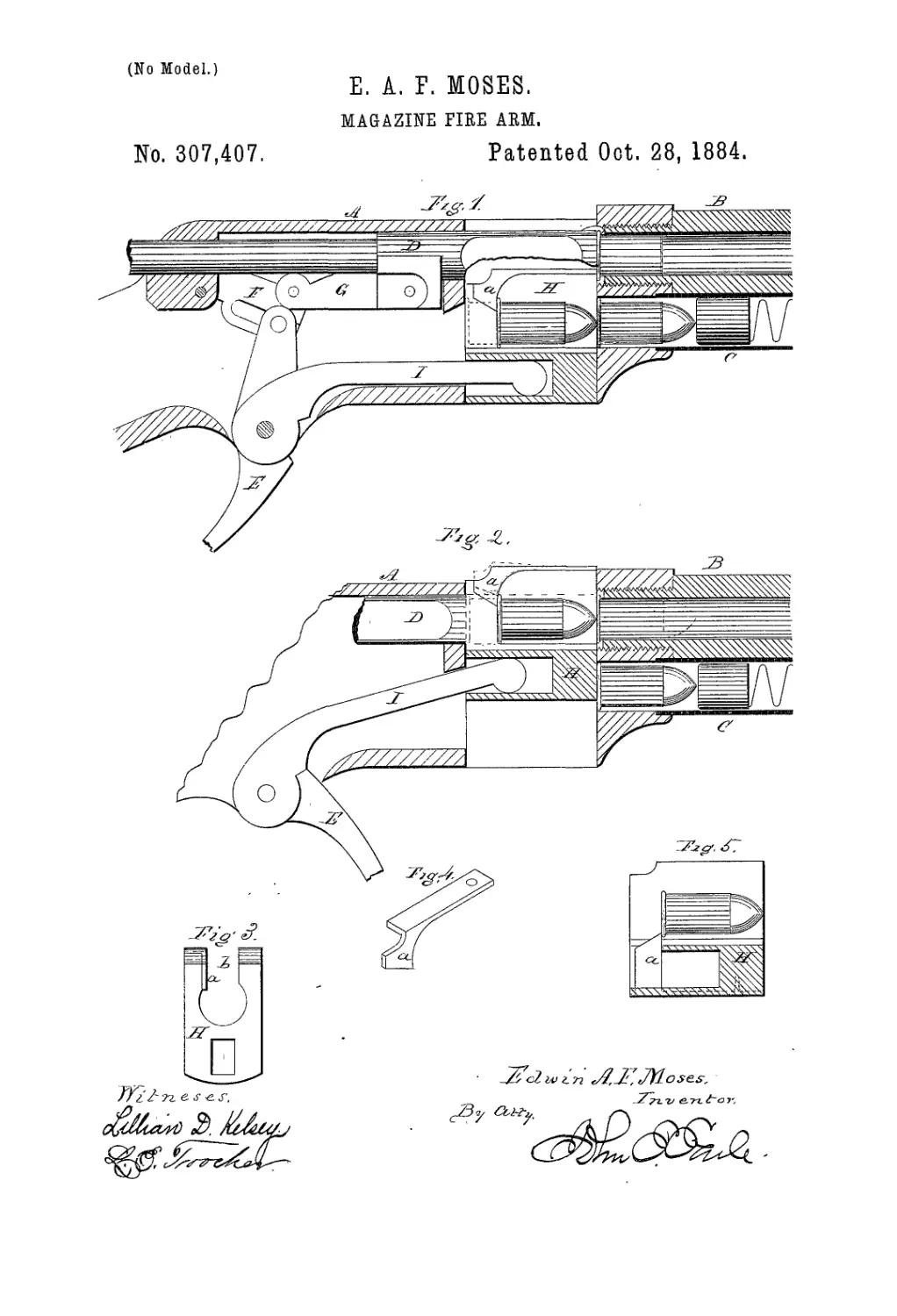
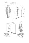
Figure 1, a sectional side view showing so
much of the mechanism of the arm as is nec-
essary to show the application of my invention
15 to the carrier, the parts of the arm being in
the normal condition; Fig. 2, a sectional side
view showing the carrier as raised to transfer
the cartridge to its position forward of the
front face of the breech-piece; Fig. 3, a ver-
го tical section through the carrier in rear of the
latch or stop; Fig. 4, a perspective view of the
spring latch detached; Fig. 5, a modification.
This invention relates to an improvement in
that class of magazine fire-arms in which the
25 carrier consists of a vertically - reciprocating
block arranged in a recess in rear of the bar-
rel, and so that on receiving a cartridge from the
magazine below the carrier is raised in front of
the withdrawn breech-piece, and then the with -
30 drawn breech-piece, passing through the car-
rier, transfers the cartridge so received from the
magazine into the chamber in the barrel, and
then the carrier returned to receive a second
cartridge from the magazine, and particularly
35 to the arm of this class known as the “Win-
chester repeating-arm.”
It is frequently desirable, in the use of rifles
for sporting and target purposes, to employ
different lengths of cartridges, but as the car-
40 rier in these arms is constructed to receive
only one certain length of cartridge, different
arms are required when different lengths of
cartridges are desired—that is to say, if the
arm be constructed for a cartridge of a certain
45 length, and a shorter cartridge be desired, if
such cartridges be introduced into the maga-
zine the rearmost cartridge will be forced to
the extreme rear of the carrier, and thus per-
mit the rear end of the second cartridge to en-
50 ter the carrier and impede or prevent the ris-
ing of the carrier to present the first cartridge.
The object of my invention is to adapt the
arm to cartridges of varying lengths; and it
consists in a latch arranged in the carrier, and
so as to form a shoulder forward of the extreme 55
rear of the carrier, and against which the head
of the shorter cartridge will abut, and there-
by operate the same as if the carrier were con-
structed for such short cartridge, and as more
fully hereinafter described. 60
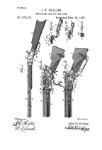
The mechanism of the arm constitutes no
part of my invention. In the illustration I
show mechanism substantially that of the
Winchester repeating - arm, and in which A
represents the receiver, В the barrel, C the 65
magazine, D the longitudinally - reciprocat-
ing breech-piece arranged in axial line with
the barrel, E the trigger-guard lever by which
through toggles F G the breech-piece is oper-
ated, H the carrier, I the lever between the 70
trigger-guard lever and the carrier, whereby
the up and down reciprocating movement is im-
parted to the carrier, all substantially the same
as in the Winchester repeating - arm. The
length of the carrier is the maximum length 75
of the cartridge adapted to be used in the arm.
In the carrier, and preferably above, I ar-
range a spring-latch, a, the nose of which ex-
tends down into the cavity in the carrier which
is to receive the cartridge from the magazine. 80
The forward face of the latch forms a shoulder
or stop in the carrier against which the head
of the cartridge will abut, as seen in Fig. 1,
and the bottom of the latch in rear of the front
face is beveled backward and upward. Such a 85
short cartridge standing in the carrier as seen
in Fig. 1, the head rests against the said stop
or latch, the stop standing in rear of the front
face of the carrier the length of the cartridge,
and as indicated in Fig. 1. In said Fig. 1 the 90
maximum length of the cartridge is shown
in broken lines, the shorter cartridge shown
in solid lines and as received from the maga-
zine. ч When the carrier is raised, as in Fig’.
2, the breech - piece is forced forward in the 95
usual manner, and passes through the recess
in the carrier, its front face striking the bev-
eled under sicle of the latch a, raises that latch,
as indicated in broken lines, Fig. 2, so that
the breech-piece passes into contact with the 100
head of the cartridge, and forces that cartridge
into the chamber in the barrel in the usual
307,407
manner, and the same as if the arm were con- |
structed with a carrier the length of which
was equal to this short cartridge.
The latch is best made to be secured to the
5 top of the carrier, as seen in Figs. 2 and 3, at
one side of the vertical slit b, through which
the reduced portion of the breech-piecc passes
as the carrier falls, the latch being a thin plate,
and so as not to interfere with such descent of
io the carrier.
The latch may be adjustable on the top of
the carrier, so as to present the front face or
stop at different positions; or different latches
may be constructed for the same arm, they
15 varying so that the front face of one may stand
at a different position from that of another.
When the longer cartridge is required to be
used, then the latch is removed. By this in-
vention the arm is readily adjusted to car-
20 tridges of varying lengths.
While I prefer to arrange the latch at the
top of the carrier, and so as to extend down
into the recess in the carrier to form the stop,
it may be introduced from below, as seen in
25 Fig. 5, and secured to the under side of the
carrier. I therefore do not wish to be under-
stood as limiting the position of the latch to
any particular part of the carrier, it only be-
ing essential that it shall be so arranged that
the nose may enter the carrier at a point be- 30
tween its extreme front face and its rear face,
and form a stop for the head of the cartridge
short of the extreme rear face of the carrier,
and yield for the passage of the breech-piece
through the carrier. 35
I claim—
In a magazine fire-arm in which a vertical-
ly-reciprocating carrier is employed to trans-
fer the cartridge from the magazine to a posi-
tion between the front face of the withdrawn 40
breech-piece and the barrel, the combination,
with said carrier, of a spring-latch arranged
to form a stop in the cartridge - recess in the
carrier forward of the rear face of the carrier,
substantially as described.
EDWIN A. F. MOSES.
Witnesses:
John F. It. Schaefer,
Wm. A. Copeeand.