/
Теги: weapons military affairs patent
Год: 1880
Текст
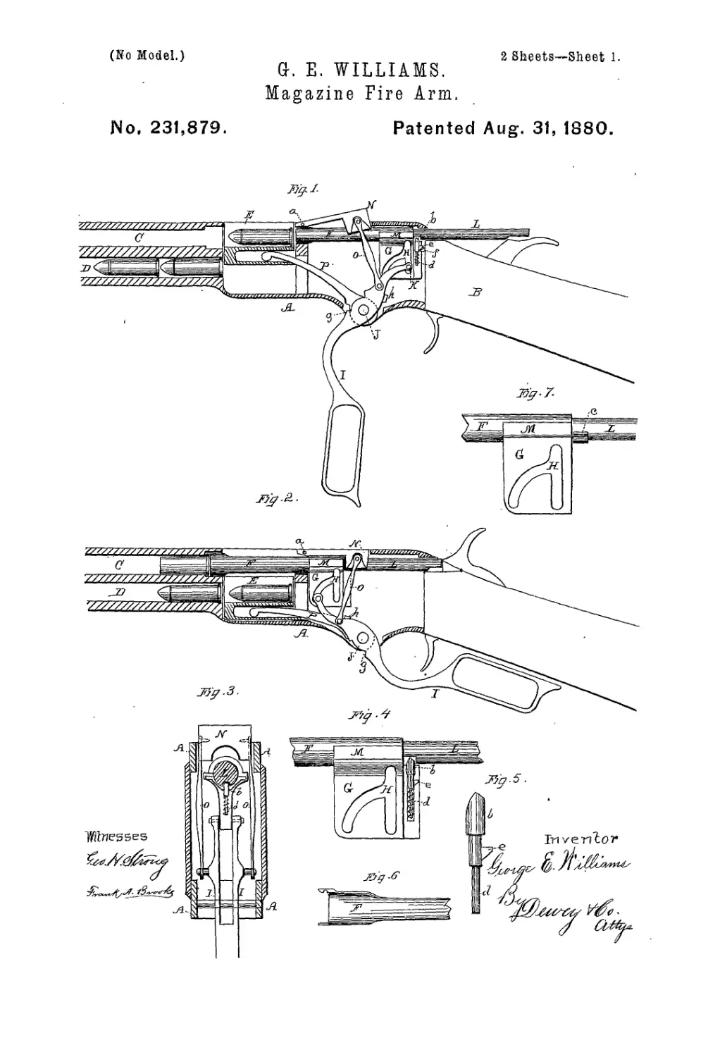
(No Model.)
2 Sheets—Sheet 1.
G. E. WILLIAMS.
Magazine Fire Arm.
Wo, 231,879.
Patented Aug. 31, 1880.
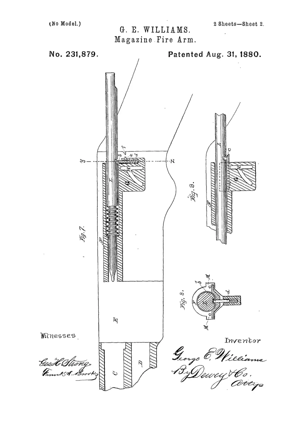
(No Model.)
2 Sheets-Sheet 2,
G. E. WILLIAMS.
Magazine Fire Arm.
No. 231,879. Patented Aug. 31, 1880.
United States Patent Office.
GEORGE E. WILLIAMS, OF SAN FRANCISCO, CALIFORNIA, ASSIGNOR OF
ONE-HALF OF HIS RIGHT TO REUBEN H. LLOYD, OF SAME PLACE.
MAGAZINE FIRE-ARM.
SPECIFICATION forming part of Letters Patent No. 231,879, dated August 31, 1880.
Application filed May 21, 1880. (No model.)
To all whom it may concern :
Be it known that 1, George E. Williams,
of the city and county of San Francisco, and
State of California, haveinvented an Improved
5 Magazine Fire-Arm; and I hereby declare
the following to be a full, clear, and exact de-
scription thereof.
My invention relates to certain improve-
ments in magazine fire-arms; and itis more es-
io pecially applicable to that class of guns in
which the cartridge is received from the maga-
zine into a carrier-block and is elevated by
this block to a level with the bore of the gun,
and is then forced into its chamber in the bar-
15 rel by a carrier-bolt or breech-pin operated by
a lever and suitable connecting links or arms.
My invention consists of a peculiarly-slotted
plate formed with the breech-pin bolt and
adapted to reciprocate the bolt by the action
20 of the guard-lever.
It also consists,in combination with the bolt,
of a hinged locking-block which is connected
with the guard-lever by links, and is thrown
up by them to allow the bolt to be retracted,
25 and is drawn down so as to lock it firmly when
it has been forced forward and the cartridge
introduced to its chamber ready for firing.
My invention further consists in a means for
locking the piston or firing-pin so that it can-
30 not be impelled against the cartridge until
after the breech is entirely closed and locked
in place, and also in a means for retracting
the firing-pin to prevent its restingin contact
with the cartridge before the latter is within
35 the chamber ready for firing.
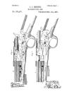
Referring to the accompanying drawings for
a more complete explanation of my invention,
Figure lisa sectional elevation of myimproved
gun, showing the breech-pin withdrawn. Fig.
40 2 is sectional elevation, showing position of
parts after firing. Fig. 3 is a transverse sec-
tion through the breech. Figs. 4, 5, 6, and 7
are details of construction. Figs. 7, 8, and 9
are details on an enlarged scale.
45 A is the frame within which the breech
mechanism is placed, and В is a portion of the
small of the stock. The barrel 0 screws into
the front of the frame, and the magazine D
lies just beneath the barrel.
50 E is the carrier-block, which moves verti-
cally in a slot or mortise within the frame, as
shown.
The breech-pin bolt F moves through the
upper part of the frame, in rear of the barrel,
and by its reciprocation forward forces a car- 55
tridge into the barrel, and when moved back-
ward it extracts the empty shell and makes
way for another cartridge, which is brought up
from the magazine by the carrier-block, these
operations not differing from those of the Win- 60
Chester or Henry rifle.
In iny invention I operate the breech-pin by
means of a block or plate, G, which projects
beneath the pin and has the peculiar-shaped
three-part slot H formed in it. The guard-le- 65
ver 1 has that portion which extends above the
fnlcinm-piii J forked or formed double, so as
to clasp the plate G, and a pin, K, passes
through the slot H, to unite the two ends of
the forked arm. This pin may have an anti- 70
friction roller upon it where it moves Within
the slot.
The inner end of the lever I is curved up-
ward from the fulcriiin-pin, as shown, and
when the outer end of the lever is thrown down 75
the pin К traverses the slot H, first moving
from the lower end in front to the top. at which
point the end of the lever is the highest, and
then moving down to the lower rear end of the
slot as the lever completes its arc of a circle. 80
The brush-bolt is meanwhile withdrawn from
the rear of the barrel, and the extractor re-
moves the empty shell, while the rear end of
the piston L forces the hammer back and cocks
the gun. 85
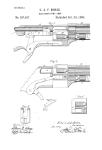
Lugs M are formed with the [date G or
breech-pin, or firmly secured thereto, so as to
project out to each side, and a locking-block,
N, is adapted to be forced down, so as to
clasp the breech-bolt and to engage these 90
lugs, and thus prevent the bolt from being
forced back by the explosion of the cartridge.
This locking-block fits into a mortise in the
top of the frame, and has an arm extending
forward to the point a, where it is hinged. 95
The side of the block which fits behind the
lugs may be curved with an arc having a
radius equal to its distance from the point a,
while the corresponding faces of the lugs M
will be convex, having the same radius. This 100
S
S31,8»д
5
ю
i5
20
25
3°
35
4°
45
5°
55
бо
will insure a close fit and a perfect lock when
the breech is closed.
In order to raise the locking-block to allow
the breech-block to be retracted links О extend
from each side of it down to the sides, of the
lever I within the frame, and the first move-
ment of the lever raises the locking-block until
it is clear of the lugs M before the lever acts
upon this bolt to retract it. When the breech
is closed this block is drawn down behind the
lugs, and will thus insure positive security and
safety.
A difficulty which has been encountered in
this class of guns is the liability of the car-
tridge to be discharged before it is seated in
the barrel, if by accident the trigger should be
pulled when the breech is partly closed. To
prevent this I employ a lock for the piston or
firing-pin, which will hold it back until the
breech has been entirely closed and locked in
its place. It consists of a catch orpin, 6, which
enters a hole or slot in the piston when the
latter is drawn back.
I have shown two methods of constructing
this pin. In one case flat steel springs extend
forward beneath the lugs M, and are secured
thereto, while their rear ends are attached to
a transverse bar, c, which carries the pins. In
the other case the pin b has a stem, d, which
extends downward into a socket in the rear
part of the plate G, and a spiral spring holds
it within plateG until a beveled lug, e, strikes
a stop, f, in the rear of the frame, distends
the spring, and forces the pin b into a notch in
the firing-pin, to secure it, until plate G moves
forward and releases lug e from stop f.
The bar c projects upon each side of the pis-
ton, and when the locking-block N is just
reaching its seat it strikes the bar and forces
it downward, thus withdrawing the pin b and
releasing the piston, so that it will be free to
be acted upon by the hammer when it falls.
In order to retract the piston or flring-pin
within the breech-bolt after the discharge of a
cartridge, so that its point will not strike the
next cartridge while it is being introduced into
the chamber, the point of the pin b is beveled,
as shown, where it enters the notch in the pis-
ton. Upon one side of the pin b is a small
projection, e, and at the rear of the chamber
in the frame is an inclined or beveled projec-
tion,/. When the breech-bolt and piston are
drawn back after a discharge the projection/
will act to force the pin b up, and the beveled
end will be pressed into the. notch or opening
in the piston, so as to retract its point within
the breech-bolt. The pin b retains it in its re-
tracted position until the breech is closed and
locked, when it is released by the action of the
block N, as before described.
The carrier-block E is moved up and down
by the direct force of the lever I without the
aid or use of any springs. This is done by
means of the lever-arm P, the rear end of
which is fulcrumed upon the pin J, between 65
the forks of the guard-lever I, while its front
end is fitted into a slot in the lower part of the
carrier-block.
The guard-lever has a shoulder, g, formed
just below its fulcrum-pin, and when the lever 70
is thrown down and forward this shoulder
strikes the lower part of the arm P and causes
it to elevate the carrier-block. When the lever
I is again thrown up or returned to its posi-
tion in closing and locking the breech a bar, 75
h, across the forks above the fulcrum-pin
strikes the top of the arm P, and thus forces
it and the carrier-block down again. Flat or
other suitable springs between the sides of the
carrier-block and the mortise in the frame pro- 80
vide sufficient friction to retain it at any point
until it is moved by the action of the lever.
The general form and many of the parts of
my gun are not dissimilar from certain guns
now made, and I do not claim these features, 85
broadly; but my invention provides a better
means of operating these parts, and a means
for making them absolutely safe, while the op-
eration of the whole of the mechanism is ef-
fected by positive movements and without the 90
aid of springs.
Having thus described my invention, what I
claim as new, and desire to secure by Letters
Patent, is—
1. The reciprocating breech-bolt F and the 95
plate G, with its slot H, as shown, in combi-
nation with the guard-lever I, forked at its in-
ner end and having the pin K, passing through
the slot H, whereby the end of the lever is al-
lowed to swing in the arc of a circle and pro- 100
duce a reciprocating movement of the bolt
without the intervention of links,.substantially
as herein described.
2. The reciprocating breech-bolt F, with its
slotted plate G, adapted to be operated by the 105
lever I, and provided with the lugs M, in com-
bination with the locking-block N, having the
links O, connecting it with the lever I, where-
by the breech-bolt is thrown forward and the
locking - block forced down simultaneously, no
substantially as herein described.
3. The reciprocating breech-bolt F, having
the piston or firing-pin L, sliding within it, in
combination with plate G, locking-pin b, pro-
vided with beveled lug e, and the stop/, on the 115
rear of the frame, whereby the pin locks the
firing-pin when the breech is open and releases
it when the breech-bolt moves forward, as set
forth.
In witness whereof I have hereunto set my 120
hand.
GEO. E. WILLIAMS.
Witnesses:
S. H. Nourse,
Frank A. Brooks.