/

Теги: weapons military affairs patent
Год: 1887
Текст
4 Sheets—Sheet 1.
C. J. ЕЦВЕТ8.
(No Model.)
No. 373,277.
MAGAZINE FIRE. ARM.
Patented Nov. 15, 1887.
(No Model.)
4 Sheets—Sheet 2.
C. J. EHBETS.
MAGAZINE FIRE ARM.
No. 373,277. Patented Nov. 15, 1887.
4 Sheets—Sheet 3.
(No Model,)
No. 373,277
0. J. EHBETS:
MAGAZINE FIRE ARM.
Patented Nov. 15, 1887.
ol-
(No Model.) 4 Sheets—Sheet 4. C. J. EHBETS. MAGAZINE FIRE ARM.
No. 373,277. Patented Nov. 15, 1887.
United States Patent Office.
CARL J. EHBETS, OF HARTFORD, CONNECTICUT, ASSIGNOR TO THE COLT’S
PATENT FIRE ARMS MANUFACTURING COMPANY, OF SAM-E PLACE.
MAGAZINE FIRE-ARM.
VECIFICATION forming part of Letters Patent No. 373,277, dated November 15, 1887. ,
Application filed July IS, 1887. Serial No. 244,597. (No model.)
To all whom it may concern:
-Be it known that I,Carl J. Ehbets,ot Hart-
ford, in the county of Hartford and S.tate of
Connecticut, have invented a new Improve-
5 ment in-Magazine Fire-Arius; and I do here-
by declare the following, when taken in con-
nection with accompanying drawings and the
letters of reference marked thereon, to be a
full,' clear, and exact description of the same,
io a,nd which said drawings constitute part of
this specification, and represent, in—
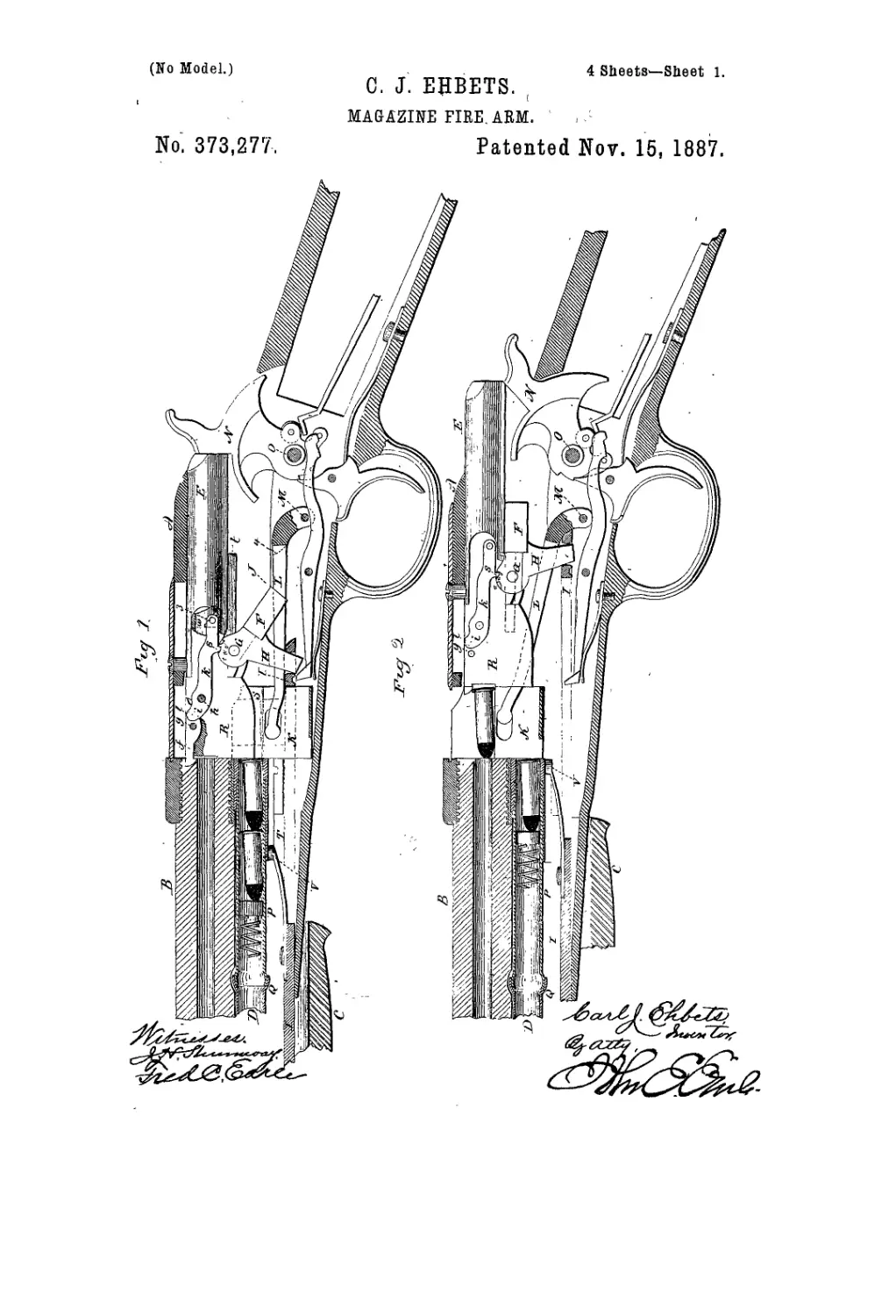
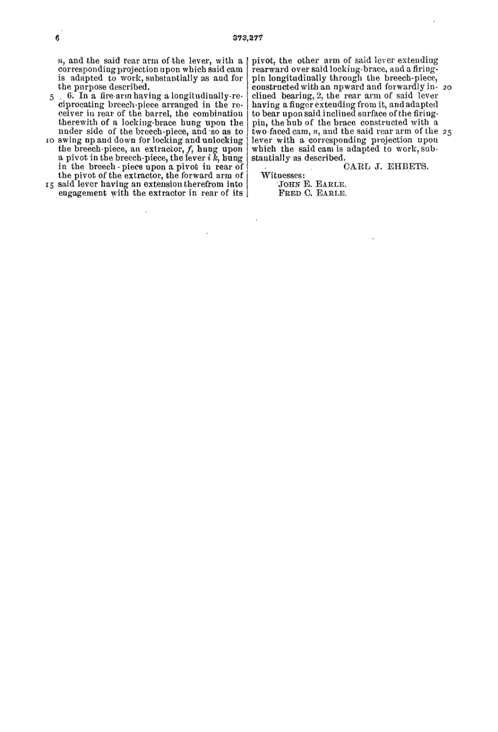
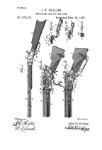
Figure 1, a sectional side view of the arm
with the parts in the normal position, or po-
sition with the brcech-piece closed; Fig. 2,the
15 same section, showing the parts as with the
breech-piece in the extreme open position;
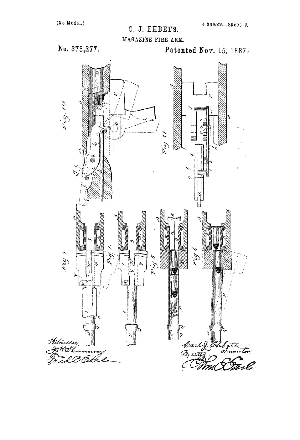
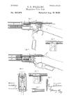
Fig. 3, a horizontal longitudinal section
through the carrier, showing under side view
of the magazine-block and portion of the slide,
20 to illustrate the engagement of the slide with
the rear end of the magazine, and in the ex-
treme forward position of the slide; Fig. 4, the
same view as Fig. 3, but showing the position
of the slide as having- commenced its rear
25 movement or about to complete its forward
movement, illustrating the transverse move-
ment of the rear end of the magazine; Fig. 5,
a horizontal longitudinal section through the
magazine and carrier, the parts in the position
3c seen in Fig. 3; Fig. 6, the same section as-in
Fig. 5, showing the parts in the position seen
in Fig. 4—that is, with the magazine turned to
one side to form the stop for the column of
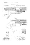
cartridges; Fig. 7, a side view of the rear end
35 portion of the magazine and of the slide, illus-
trating modification of engagement between
the magazine and slide; Fig. 8, an under side
view of the magazine-block, showing the same
modification; Fig. 9, atop view of the slide,
4.0 showing the same modification.; Fig. 10, a sec-
tional side view of the breech-piece and the
locking-braec, illustrating the operation of the
extractor, enlarged; Fig. 11, a top plan view
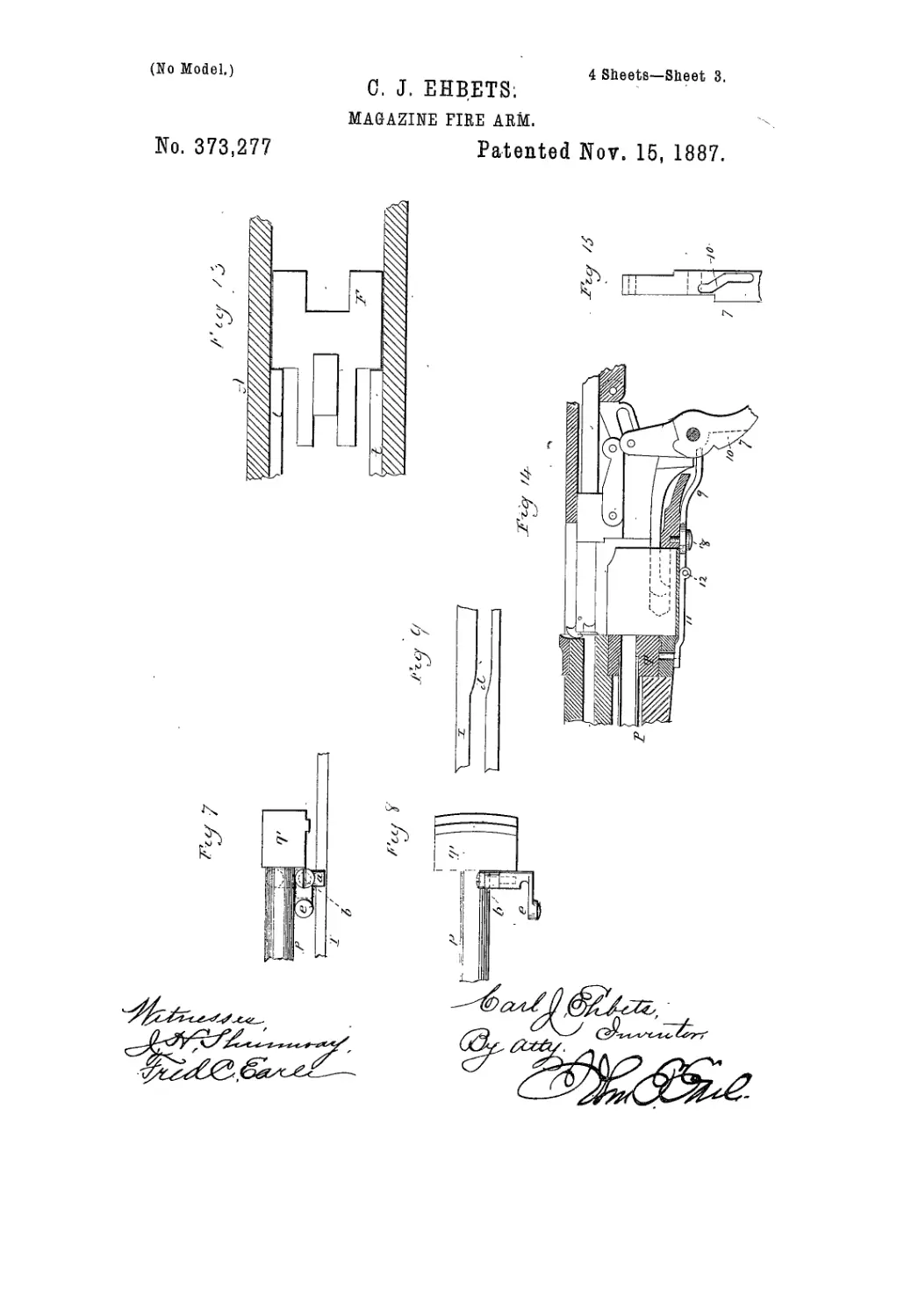
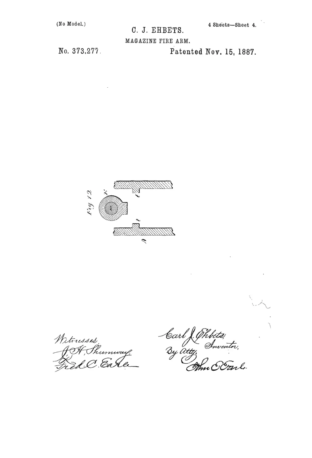
of the same,enlarged; Fig. 12, a transverse sec-
45 tion through the receiver, showing the ribs t,
against which the brace bears as it passes rear-
ward in the opening movement of the breech-
piece; Fig. 13, a horizontal longitudinal sec-
tion through the receiver, looking upward,
50 showing the same ribs and the brace as hav-
ing passed upward over the. rear ends of the
ribs; Figs. 14 and 15, modifications in the
operation of the magazine ent-off.
This invention relates to an improvement in
that class of magazine fire-arms in which the 55
breech-piece is arranged in rear of me barrel
and in line therewith, to be moved backward
in opening and forward in closing the breech,
and in which the magazine is arranged be-
neath the barrel, with a carrier-block arranged 60
in the receiver in rear of the barrel, and into
which a cartridge will pass from the magazine
when the carrier is in the down position, so
that as the carrier is raised it will bring a car-
tridge into line with the barrel,and from which 65
the cartridge is transferred to the barrel as
the breech-piece moves forward through the
earlier, and is an improvement upon the arm
for which Letters Patent of the United States,
No.332,203, weregrantedtotheassigneesinthis 70
application, December 8,1885, as the invention
of F. F. Knous. As in that patent, so in this,
the movement is imparted to the mechanism,
of the arm by means of a handle beneath the
barrel forward of the receiver, adapted to 75
slide longitudinally backward and forward.
A represents the receiver, to the forward end
of which the barrel В is secured in the usual
manner, and opens into the receiver at its rear
end. 80
C is the handle beneath the barrel, arranged
to slide parallel to the magazine D, which is
arranged longitudinally beneath the barrel in
the usual manner, and so as to open into the
receiver below the barrel at the rear; E, the 85-
longitndinally-moving brcech-piece arranged
in the receiver in line with the barrel. Upon
the under side of the breech-piece, near its for-
ward end, the locking-brace F is hung upon a
pivot, G, and from the brace ап'агпц H, ex- 90
tends downward through an opening in the
longitudinal slide I. The said slide extends
forward through the receiver, and is secured
to the handle C, so as to move with it. In the
receiver abutments .Tare formed, against which 95
the brace F may stand when the brcech-piece
is in the closed position, as seen in Fig. 1, and
as in the patcut before referred to, and so that,
standing in the closed position, if the handle
be moved rearward the first part of its rear- 100
ward movement will turn the brace F upward
from the abutments J, and so as to leave the
2
393,277
breech-piece free to move rearward under the
continued rear movement of the handle.
К represents the carrier, which is in the
form of a block arranged to move vertically
' 5 in the receiver, and is of a length for the long-
est cartridge required. The carrier is raised
by means of a lever, L, hung upon a pivot,
M, at the rear, preferably below the rear end
of the slide I, and so that as the slide moves
io rearward beneath the body of the lever it will
strike the lever as the slide approaches its ex-
treme rear position, and after having opened
the breech-piece, and so as to act as a earn
upon the lever L and raise its forward end, as
15 seen in Fig. 2. The forward end being con-
nected with the carrier, imparts corresponding
upward movement to the carrier, as from the
position seen in Fig. 1 to that seen in Fig. 2.
The breceh-pieee is adapted to work through
20 the carrier in its forward movement, while the
carrier stands in the up position, in the usual
manner for this class of arms, not necessary to
be particularly described.
The brace F works above the lever L, and
25 so that as the breech-piece moves forward and
comes to the closed position, the brace being
above the lever L, will strike upon the top of
the lever aud force it to its down position, as
seen in Fig. 1, returning the carrier to the
30 down position. The carrier'lever may, how-
ever, be operated as iu the patent before re-
ferred to, the method of operaiing the lever
to raise and lower the carrier constituting no
part of the present invention. When the car-
35 rier is iu the down position, as seen in Fig. 1,
thecartridge chamberin thecarrier is brought
iuto line with the magazine, aud so that the
rear cartridge in the magazine may be forced
iuto the cartridge chamber in the carrier, and
40 then as the carrier rises it brings the cartridge
so introduced into the carrier in lihe-wlth the
barrel, as seen in Fig. 2, and so that when the
breech-piece is advanced with the carrier and
the cartridge in this position the breech-piece
45 will force the cartridge from the cartridge-
chamber in the carrier into the barrel in the
usual manner for this class of arms.
The hammer N is hung upon a pivot, O, and
so as to be thrown to fnll-cock under the rear
50 movement of the breech-piece, as usual in this
class of arms.
This arm is designed with special reference
to the smaller size cartridges—say No. 22—
and which are made of various lengths. . It is
55 desirable tliat an arm adapted for this smaller
size of cartridge should also be adapted to use
either of the various lengths; but it will be
seen that in a carrier of this character, if it be
sufficiently long to take the longest cartridge,
60 unless there be some provision, to the con-
trary, in the use of shorter cartridges not only
would the rearmost cartridge-pass from the
magazine into the carrier, but the next or sec-
ond cartridge would follow the first to some
65 extent onto.the carrier, and so as to stand be-
tween the carrier and magazine and prevent
the upward movement of the carrier to trans-
fer the first cartridger'"'!! is therefore neces-
sary to provide some means to prevent the
second cartridge from following the first or ex- 70
tending iuto the carrier.
In the patent to which I have referred the
magazine is formed in two parts, D represent-
ing the principal part of the magazine, which
extends to appoint near the rear end of the 75
barrel, and to the rear end of the part D the
rear portion, P, of the magazine is hinged, as
at Q, and so as to'swing beneath the barrel in
a_ horizontal plane, the part P extending to the
carrier, so as to form practically a contiuua- 80
tion of the principal part of the magazine di-
rectly into the carrier in the receiver, aud as
seen in Fig. 5, and so that when iu line with
the cartridge-chamber in the magazine, as seen
iu Fig. 5, the cartridges in the magazine are 85
free to pass into the cartridge-chamber in the
carrier; buttopreventtbeiustantaneons move-
ment of tho rear cartridge iuto the carrier
when the cartridge chamber in the carrier
comes into line therewith the breech-piece E 90
is constructed withm downward projection, R,
which extends down iuto the cartridge-cham-
ber S in the magazine, (see Figs. J and 5,) and
so as to abut against the rearmost cartridge in
the magazine when the breech-piece is in the 95
closed position, as seen iu Fig. l,and as in the
patent before referred to, aud so that as the
breech-piece moves rearward the rearmost car-
tridge will simply follow the breech-piece and
pass into the carrier; but the movement of the ire
cartridge will be no faster than that of the
breech-piece.
The part P of the magazine is hinged, as be-
fore described, so that it ma.y be turned to one
side of the receiver, as indicated iu broken 105
lines, Fig. 6, so far as to permit the introduc-
tion of cartridges to the magazine, as in the
patent before referred to. The rear payt of
the magazine terminates in a block, T, which
works transversely through the forward cud no
of the receiver.’ This block stands above the
slide I, and in the under side of the block T is
a cam-shaped groove, U. (See Figs. 3 and 4.)
From the slide I is an upwardly-projecting
stud, V, which works through the groove U as 115
.'the slide moves backward and forward. The
stud V is represented as part of, an arm .ex-
tending from the slide.
' When in the extreme forward or closed po-
sition, as seen in Fig. 3, the stud V, standing 120
in the groove U, holds the block T, or rear
end of the magazine, directly in line with tho
cartridge-chamber S of the carrier K, as.seeu
in Figs. 3 aud 5. The groove U turns Qut of
the direct longitudinal-line near its forward 125
end, and so that as the slide I commences its
rear movement the stud V acts upon the cain-
shaped groove U and forces the block T slightly
tO one side, as seen in Figs. 4 and G, and so far
as to turn the rear end of the magazine out of 130
line with the cartridge-chamber, as indicated
in said Figs. 4 and 6.
The turning of the magazine to oueside oc-
curs before the shortest cartridge can have
373,277
3
slide I. This groove is of cam shape, corre-
sponding to the cam shaped groove U of the
block T, before described, and as seen in Fig. 70
9, and so that as the slide is moved backward
for the operation of the mechanism of thearm
the first part of the movement will, through
the stud a, impart the required transverse
movement to the block, to bring it to the po- 75
sition indicated in Fig. G, to prevent the escape
of the second cartridge into the magazine. The
stud ft is necessarily hinged to the block, be-
cause otherwise it would prevent the move-
ment of the block to the position for opening 80
the magazine for the insertion of cartridges.
On the hub of the stud a handle, e, projects,
by means of which thestud may be turned up-
ward out of the groove in the slide I, as indi-.
cated in broken lines, Fig. 7, and when so 85
turned upward it is free from the groove in
the slide I, and consequently may be turned
to the extreme outward position for charging,
and when returned to its closed position the
stud « will then be returned downward into 90
the groove in the slide. Under this arrange-
ment the magazine is always in position when
the stud is in the groove, and cannot escape
from that position.
The smaller class of cartridges are usually 95
made rim-fire. Under the rapid manipula-
tion of the arm there is danger of premature
explosion from the extractor striking the head
of the cartridge as the breech-piece approaches
the closed position. In the usual construction 100
the extractor is of a spring character, so as to
ride over the head of the cartridge under the
pressure of its spring, so that the blow of the
extractor upon the head of the cartridge is one
of considerable power, and so that under rapid 105
manipulation of the arm premature explosion
from this cause may occur. To avoid this
difficulty I hang the extractor/upon a pivot,
y, in the breech piece in the usual position.
[ In the brecch-piece, on a pivot, h, in rear of no
the pivot of the extractor, 1 hang a two-armed
lever, i k. (See Fig. 1; also seen in Figs. 10
and 11, enlarged.) The arm i is provided with
a stud, Z, which extends inward over a pro-
jection from the extractor in rear of its pivot. 115
The arm к extends longitudinally rearward
over the' locking-brace F. The lever i к is
adapted to swing vertically, as indicated :by
broken lines, Fig. 10, and so that as the rear
arm, Л-, is raised it will depress the rear end 120.
of the extractor and raise the forward or hooked
end, as indicated in broken lines, Fig. 10, or,
when left free, the extractor will be turned
downward to its normal position, as seen in
Fig. 10. To force the extractor to this down 125
or normal position, the rear or tail end of the
extractor terminates in the form of a spring,
hi, which bears upon the top of the breech-
piece, and which spring is compressed as the
nose end of tlie extractor is raised, and as in- 130
dicated in Fig. 10, the spring being sufficient
to hold the extractor in engagement with the
head of the cartridge in the usual manner for
spring-extractors.
passed from the magazine into the carrier, and
it takes the column of cartridges so far out of
line with the cartridge-chamber in the maga-
zine that the head of the next, or second car-
5 fridge will strike the forward end of the car-
rier, as seen in Fig. G, and be prevented from
passing into the carrier, so that whether the
cartridge already in the carrier be the full
length of the carrier, as seen in Fig. G, or
ic shorter, as indicated in broken lines, Fig. 6,
it will be forced into the carrier by the maga-
zine-spring acting through the column of car-
tridges, but will then be leftfree, and the next
eartridge will he prevented from passing into
15 the carrier to interfere with the movement of
the carrier.
After the rear end of the magazine has been
turned out of line with the carrier, as de-
scribed, thegroove continues in a straight line
20 parallel with the path of the stud V, as seen
in Fig. 4, and so that the slide carrying the
stud A7 will continue its movement, thestud V
continuing iu the straight-line groove in its
entire rear movement. Then, on the return of
25 the slide in closing the breech-piece, the stud
V will move forward in the groove U, and,
continuingits movement through that groove,
will, as it passes the bend in the groove, re-
turn the rear end of the magazine into line with
30 the cartridge-chamber, as indicated in Fig. 4.
To limit the extreme opening movement of
therear end ofthe magazine, theblockT is con-
structed with a recess, AV, on one side of the
groove, at its forward end, as seen in Figs. 3
35 and 4, and which recess, when the slide is in
its extreme forward position,.is in line with
the stud V, as indicated in Fig. 3, and so that
when in that position the block may be turned
to the charging- position, as indicated hi broken
40 lines, Figs. 3 and 6, the recess AV permitting
it to move over the stud; but the end of the
recess serves as a stop to arrest the block
when it is moved sufficiently far for charging
purposes. The recess W also performs another
45 important purpose, and that is to prevent the
rear movement of the slide to actuate the
mechanism of the ai m. unless the rear part of
the magazine be in its proper position, for if
the block be not returned to its home position
5c before the slide commences its rear movement,
then the rear side of the recess AV will stand
in the path of the stud and prevent the rear
movement of the slide. Consequently thearm
cannpt be operated unless the magazine be in
55 proper position to deliver the cartridges to the
carrier.
The transverse movement of the rear end.of
the magazine, to serve as a stop for the column
of cartridges after one cartridge shall have
60 entered the carrier, may be produced by form-
ing the cam-groove in the slide and thestud
on the magazine, instead of vice versa, as I
have described. This modification I illustrate
in Figs. 7, 8, and 9.
65 On the forward end of the block T, I hinge
a stud, a, upon a transverse pivot, b, the said
stud a extending down into a groove, d, in the
4
373,277
To actuate the lever i к to operate the ex-
tractor, the hub of the locking-brace is con-
structed with a cam, n, on the periphery,there
being a reeess, o, on the rear side of the cam
5 and a recess, r, on the forward side of the cam,
as seen in Fig. 11. The front face of the cam
n is inclined from the outside forward, asseeh
in Fig. 11, and on its rear face is inclined
downward and backward, as seen in Fig. 10.
io The arm к is constructed with a downwardpro-
jection, s, which is adapted to enter either of
the recesses о r on the hub of the brace. This
arm is also thin and of elastic metal, as steel,
so that it may spring outward, as indicated
15 in broken lines, Fig. It, and return under its
own elasticity. When the breech-piece is in
the fully-closed position and the brace in the
locking position, (seen in Fig. l,)the projection
s of the arm к stands in the recess r forward
20 of the сага n оц the brace, and the extractor
stands in its normal position as engaging the
head of the cartridge,and is there held by its-
own spring. As the brace is turned from the
locking position, asiudicated in broken lines,
25 Fig. 10, the cam n turns forward and by its
incline passes inside the projection s of the
атт к and forces that arm к outward, as indi-
cated in Fig. 11, without effect upon the ex-
tractor. The brace Tthus turned to the un-
30 locking position (indicated in Fig. 10,) strikes
longitudinal ribs t (§ee Figs. 12 and 13) ou
the sides of the receiver and rides thereon,so
t'hat it is prevented from turning to its ex-
treme up position; but as the brcech-piece ap-
35 proaches its extreme open position the ribs t
terminate, as seen in Fig. 13, and the brace is
free to rise to the position indicated in Fig.
10 and stand in rear of the rear cuds of the
ribs t, as indicated in -Fig. 10. In so doing
40 the cam n passes beyond the projection s of
of the shoulder,and so that the projection will
spring into the reeess о in rear of the cam n.
Then when the closing movement commences
the first part of the closing movement is to
45 draw the brace downward, so that it may es-
cape from the rear ends of the ribs t, as indi-
cated in broken lines, Fig. 10, and then be free
to pass forward with the breech-piece. In this
first downward movement of the brace the
50 back or rear side of the cam n acts upon the
projection s of the arm к and causes that-arm
to rise, as indicated in broken lines, Fig. 10,
and correspondingly raise the nose of the ex-
tractor. After the brace has been thus turned
55 to raise the arm к it holds the arm к in that
position until the brace shall have passed so
far forward that it may drop against its abut-
ments, as seen in Fig. 1, and this is when the
brcech-piece has reached its extreme closed
60 position. As the brace'drops into its locked
position, the cam» escapes from the projection
n of the arm к and permits that' arm to drop
into the recess r, it being forced so to do by
the extractorspring,which tends to raiso the
65 forward cud or arm,г,of the lever. By this ar-
rangement theextractoris mechanically raised
above the head of the cartridge and is held in
that position until' the breech-piece is closed
and the nose of the extractor has passed to a
position forward of the front face of the flange 70
of the cartridge, when it is permitted to drop
and engage the flange of the cartridge, so that
on the rear movement of the b'feech-piece the
cartridge will be snre to follow, as with com*
mon extractors; hence there is no liability of 75
the extractor coming in contact with the head
of the cartridge, so as to produce explosion.
The ar,m к of the lever i к is also utilized as a
retractor for the firing-pin u. Fig. 10 repre-
sents the firing-pin, which is arranged in the 8c
forward part of the breech-piece and in a posi-
tion to strike the flange of the cartridge.
The firiug-pin extends through the breech-
piece in the usual inaupcr, and on the under
side of its rear portion, w, is a notch, 2, the 8;
rear side of which is inclined upward and for-
ward. Into this notch a finger, 3, on the arm
k, extends, and so that when the arm к is in
its down position the firiug-pin is free to
be forced to its extreme forward position, as 90
indicated in Fig. 10; but as the arm /crises the
finger 3 operates against the inclined surface
of the notch 2 as a cam, and causes the firing-
pin to retreat, as indicated in broken lines,
Fig. 10; hence, because the arm к is held iu 95
the up position daring the forward movement
of the brcech-piece, and until the extreme
closed position is reached, it follows that the
firing-pin is held out of possible contact with
the cartridge until after the breech piece shall 100
have reached its’extreme forward and locked
position.
The lever for operating the extractor may be
omitted and the common extractor employed.
In such ease, to provide for the retraction of 105
the firiug-pin, the retracting-finger may be
made as a part of the brace, as indicated in
broken lines, Fig. 10, so that as the brace rises
it will force the firing-pin rearward.
I have stated that the carrier-levcr may be nc
operated as I have illustrated, or as in the
patent before referred to. It may, however,
be raised directly by the arm II of the locking-
dog by making the rear end of the recess in
the lever through which the arm IT works of 115
a shape indicated at 4 in broken lines, Fig. 1,
and so that as the arm approaches its rear po-
sition it will act as a cam upon the lever to
raise it and the carrier.
The method which I have described to form 120
a stop for the column ofcartridges to prevent
the second cartridge from following the first
onto the carrier may be utilized in many arms
of this class, in which the mechanism differs,
essentially, from that illustrated and de- 125
scribed—as, for illustration, in Fig. 14 I rep-
resent an arm the mechanism of which is that
commonly known as the “Winchester” armj
and in which the brcech-piece and carrier are
operated by a lever hung in the receiver be- 130
low the breech-piece, and so that the lever
swings downward and forward in the opening
373,277
5
5
io
15
20
25
3”
35
40
45
.50
55
бо
65
movement. ' The magazine and its block T
are in the same arrangement as I have before
described.
To impart to the rear end of the magazine a
transverse movement to produce the check or
cut-off between the magazine and carrier, a le-
ver may be introduced between the operative
lever 7 and the head T.- This lever is repre-
sented as hung upon a pivot, 8, upou the un-
der side of the receiver, and between the pivot
of the lever 7 and the magazine-block T, one
arm. 9, extending rearward, stands in a cam-
shaped groove, 10, in the hub of the lever 7.
(See Fig. 15.) The other arm, 11, extends for-
ward and is hung to the lower side of the block
T. The cam in the operative lever 7 imparts a
transverse vibratory movement to the lever 9
11, which is communicated to the magazine, and
this transverse movement is the same as that
which I have heretofore described as imparted
by means of the handle forward of the receiver.
Under this modification, in case it is desirable
to load the magazine, as I have heretofore de-
scribed, by throwing the magazine out at one
side of the receiver, the forward arm, 11, of
the lever should be hinged to the rear portion—
say as at 12, Fig. 14—which will permit the
forward arm, 11, of the lever to be turned
downward and out of engagement with the
magazine, so as to leave the magazine free to
be thrown outward sufficiently far to expose
the rear end of the magazine. In case, how-
ever, the magazine is to be charged through
the side of the receiver, as common in this
class of arms, then there will be no occ.nsiou
for disengaging the magazine from its lever. I
therefore do not wish to be understood as lim-
iting this part of my invention to the particu-
lar mechanism of the arm described; nor do I
wish to be understood as limiting it to a maga-
zine made in two parts, the forward part be-
ing rigidly fixed, while the rear part swings,
as it may be applied to a magazine made in a
continuous tube and adapted to swing bodily,
a modification which it is unnecessary to illus-
trate.
The mechanism which I have described for
operating the extractor to prevent its possible
contact with the cartridge may also be em-
ployed with other reciprocating breech-picces
having a locking-brace of similar character to
the one described, but in which the breech-
piece aud other parts are moved by mechan-
ism of other character, and may be used in
single breech-loaders. I therefore do not wish
to be understood as limiting this part of my
invention to the particular construction of arm
which I have described.
I claim—
1. In a magazine fire-armin which the maga-
zine is arranged longitudinally beneath the bar-
rel and opening into the receiver at the rear,
aud which is adapted to swing at its rear end
out of line with the cartridge-chamber in the
carrier, the combination therewith of a cam
between the operative mechanism of the arm
and said magaziuc, and substantially as speci-
fied, whereby during the first part of the rear
movement of the breech-piece said rear end of"
the magazine is automatically thrown out of 70
line with the cartridge-chamber in the carrier.
2. In a magazinefire arm in which the maga-
zineisarranged longitudinally beneaththebar-
rel and adapted to swing at its rear end out of
line with the cartridge-chamber in the carrier, 75
the combination therewith of a longitudinal
slide moving parallel with the axis of said
magazine, the said magazine and slide, the
one provided with a stud and the other with
a cam-shaped groove through which the said 80
stud may work, substantially as described,
and whereby under the movement of said slide
in one direction the* rear end of the magazine
will be turned to one side of its normal posi-
tion and on the fetnrn of the slide the maga- 85
zine will be retured to its normal position.' ’
3. In a magazine fire-arm in which the
magazine is arranged longitudinally beneath
the barrel, aud in which the mechanism of the
arm is operated by a slide extending through 90
the front end of the receiver, and provided
with a handle, and in which the rear end of
the magazine is adapted to be turned out of
line with the opening into the receiver, the
magazine provided at its rear end with a trans- 95
versely-gnided sliding block, the said block
constructed upon itsunderside with a longitu-
dinal groove, the said groove of cam or bent
shape, the said slide provided with a stud
adapted to work through said groove in the too
said block of the magazine, substantially as
and for the purpose described.
4. In a magazine fire-arm in which the mag-
azine is arranged longitudinally beneath the
barrel, and in which the mechanism of the arm 1C5
is operated by a slide extending through the
front end of the receiver, aud provided with a
handle, aud in which the rear end of the maga-
zine is' adapted to be turned out of Hue with
the opening iuto the receiver, the magazine no
provided at its rear end with a transversely slid-
ing block, the said block constructed with a
groove upou itsunde^ surface, said groove ter-
minating in a transverse recess, W, at its for-
ward end, the said slide provided with a stud 1 r5
adapted to work through said groove and
come into a line with said recess when said
slide is iu its extreme forward position, sub-
stantially as and for the purpose described.
5. In a fire-arm having alongitudinally-re- 12c
ciprocating breech-piece arranged in ;the re-
ceiver in rear of the barrel, the combination
therewith of a locking-brace hnugupbn the un-
der side of the breech-piece, and so as to swing
up and down for locking and unlocking the 12
breech-piece, an extractor, f, hung Upon a
pivot in the bre.ech-piece,the lever i k,hung iu
tlfe breech-piece upon a pivot in rear of the
pivot of the extractor, the forward arm of said
lever having au extension therefrom into en- 1
gagement with the extractor iu rear of its
pivot, the other arm of said lever extending
rearward over the said locking-brace, the hnb
of the brace constructed -with a two-faccd cam,
,277
pivot, the other arm of said lever extending
rearward over said locking-brace, andafiring-
pin longitudinally through the breech-piece,
constructed with an upward and forwardly in- 20
dined bearing, 2, the rear arm of said lever
having a finger extending from it, and adapted
to bear upon said inclined surface of the firing-
pin, the hub of the brace constructed with a
two faced cam, n, and the said rear arm of the 25
lever with a corresponding projection upon
which the said cam is adapted to work, sub-
stantially as described.
OA.BL J. EHBETS.
Witnesses:
John E. Eable.
Fred C. Earle.
6 373,
n, and the said rear arm of the lever, with a
corresponding projection upon which said cam
is adapted to work, substantially as and for
the purpose described.
5 . 6. In a lire arm having a longitudinally-re-
ciprocating breech-piece arranged in the re-
ceiver in rear of the barrel, the combination
therewith of a locking-brace hung upon the
under side of the breech-piece, and so as to
io swing npand down for locking and unlocking
the breech-piece, an extractor,/, hnng upon
a pivot in the breech-piece, the lever i It, hung
in the breech - piece upon a pivot in rear Of
the pivot of the extractor, the forward arm of
15 said lever having an extension therefrom into
engagement with the extractor in rear of its