/


Теги: weapons military affairs patent
Год: 1887
Текст
(No Model.)
J. W. MULLINS.
REPEATING GUN OR FIRE ARM.
United States Patent Office.
JOHN W. MULLINS, OF LONDON, KENTUCKY.
REPEATING GUN OR FIRE-ARM.
SPECIFICATION forming part of Letters Patent No. 373,410, dated November 15, 1887.
Application filed July 23, 1887. Serial No. 245,548. (No model.)
To all whom itjnay concern:
_ Be it known that I, John W. Mullins, a
citizen of the United States, residing at Lon-
don, in the county of Laurel, State of Ken-
5 tucky, have invented certain new and useful
Improvements in Repeating Guns or Fire-
Arms, of which the following is a specification,
reference being had therein to the accompa-
nying drawings.
io This invention has relation to improvements
in magazine fire-arms; and among the objects
of the invention are to reduce the number of
parts, simplify the construction, and thus
lighten the weight of the gun and reduce the
15 cost of its manufacture, and render the same
less liable to get out of order.
Other objects and advantages of the inven-
tion will hereinafter appear, and the novel
features thereof will be particularly pointed
20 out in the claims.
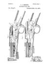
Referring to the drawings, Figure 1 is a side
elevation of a magazine fire-arm constructed
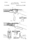
in accordance with my invention. Fig. 2 is a
substantially central longitudinal section of the
25 same, the stock and barrel being broken away,
and the parts being in position assumed when in
the act of elevating a cartridge to the breech.
Fig. 3 is a similar view, the parts being shown
in the position assumed after the cartridge has
30 been placed in the breech and the piece ready
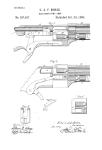
for firing. Figs. 4,5, and 6, the first two being
in perspective and the latter in section show
details hereinafter referred to.
Like letters refer to like parts in all the
35 figures of the drawings.
In the drawings, A represents the barrel,
В the magazine, C the lock-plate, and D the
stock, all of which are of ordinary construc-
tion.
40 E and E' represent the hammer and trigger,
respectively, the latter taking into the .dog of
the former, and being actuated by the usual
spring. A bolt, F', is passed through the
lock-chamber F, said bolt being provided with
45 screw-threads at one end for connection with
the lock-plate, and formed with a bearing in-
termediate its ends.
G represents the operating-lever, which
comprises the guards G' at its rear end, and
50 the boss of hub G2, having the perforation G3,
extending entirely through the same. The
lever G is mounted and freely swings upon
the bolt F', said bolt passing through the ap-
erture G3. The thickness of the lever is such
as to loosely fit the lock-chamber, and in this 55
way the lever G has a bearing along the entire
bearing-surface of the bolt and at each side of
the chamber, by which construction the life
of the gun is increased, the parts being less
liable to become loose on said bolt. The for- 60
ward end of the lever G is formed with the
finger G4, the shoulders G6 G°, and the inter-
mediate recess, G7, all as shown in Fig. 4.
H represents the firing-bolt, which is mount-
ed in the usual breech-bore in line with the 65
barrel and provided with the ordinary firing-
pin, H'. Any shell-extractor may be mounted
on the firing-bolt H; but in this instance I
have provided a flat spring-latch, H2, seated
in a longitudinal groove and provided with a 70
latch end, H3, adapted to pass within a notch,
A', in the barrel, and over the rim of the shell
(see Fig. 3,) the operation of said extractor
being hereinafter described.
Upon the under side of the bolt H is formed 75
the shoulders H4 H5 H6 and the intermediate
recesses, H7 H8, by which shoulders and re-
cesses and those on the lever the bolt is recip-
rocated in the act of loading and extracting
the shell. 80
Surrounding the boss G2 on the lever G is
formed an annular recess, GB, into which aud
loosely fitting the boss is seated an annular
ring, J', said ring being of such a thickness as
to bring the same flush with the surface of the 85
lever. Integral with the ring J' and project-
ing therefrom is a bifurcated arm, J, the lower
bifurcation being formed as a spring-finger, J2,
and the upper bifurcation being formed as a
cartridge-hoist, J3, the end of which is grooved 90
and bent, as at J6, for a purpose hereinafter
described. A lug, J4, projects upwardly from
the rear end of the hoisting-finger J3 and sup-
ports the front end of the bolt in a horizontal
position when the same is withdrawn for the 95
purpose of ejecting and loading.
This being the construction, the operation
is as follows: The magazine being filled in the
usual manner, and supposing the piece to have
been discharged, I will proceed to describe the ico
operation of withdrawing the shell, ejecting
the same, and loading the piece. The lever G
is grasped by the guard and swung down and
forward, and in the act of so doing the shoul-
2
373,410
der G6 first comes in contact with the shoulder
H4 of the bolt H and draws said bolt to the
rear. At the same time that this takes place
the curve G7 in the front end of the lever and
5 in the rear of the shoulder G° comes in con-
tact with and rides upon a rounded protuber-
ance, E2, formed on the front of the hammer
E, and slightly raises the latter, which raising
thereof is caused by the shoulder G“ coming in
io contact after it passes by the shoulder on the
bolt, and in this manneris the hammer brought
to a full-cock. Now as the shoulder G6 passes
the shoulder H4 of the bolt the finger G4 of
said hammer comes in contact with the shoul-
15 der H6 and completes the backward recipro-
cation of the bolt, thefiring-pinof which comes
in contact with the face of the hammer just
before it reaches full-cock. As the lever is
swung downward, the end of the guard formed
20 by the annular recess Gs comes in contact with
the under side of the arm J—this, however, not
until the operation just described has taken
place, leaving the bolt in the position shown
in Fig. 2. As the guard comes down, the bi-
25 furcated arm J is raised from its lowest posi-
tion (in which the hoist J3 is in a horizontal
line with the magazine B, and from which it
has received a cartridge) to a point in which
the hoist is in a line with the barrel. As the
30 bolt His thrown back it of course extracts the
empty shell from the barrel and carries it to
the rear and in a line with the opening F2 in
the top of the lock-chamber, and the firing-
pin coming in contact with the face of the
35 hammer just before it reaches full-cock forces
the shell slightly to the front. At this junc-
ture the lug J4 on the hoist J3 is brought in
contact with the rear end of the shell and pro-
duces a farther upward tilt of the same, at
40 which time the new cartridge comes in contact
with the under side of the shell. The latter is
forced out of the opening F2. By swinging the
lever G to the rear, in which position it is
locked—in this instance by means of a spring-
45 screw, D', seated in the stock, taking into a
recess, G9X, by the rear end of the lever—the
operation just described is reversed, the bolt
H first being forced to the front by means of
the finger G4 and shoulder G6 acting against
50 the shoulders H“ H5, and by this forward move-
ment of the bolt the cartridge is firmly held
pressed into the breech of the barrel. At the
time the cartridge is partly entered in the bar-
rel and the bolt is completing the operation the
55 front face of the shoulder H6 comes in contact
with the lug J4, and the bifurcated arm is thus
forced down to its lowest position to receive a
new cartridge from the magazine. The ham-
mer having been left at a full-cock, the piece
6c may be discharged or let down to a safety-cock.
By the operation described the piece may
be discharged and the shell extracted and
ejected, the hammer cocked, and the piece re-
loaded all by operation by the lever G.
65 It will be noticed that when the hoist is ele-
vated to the barrel, and by the time that the
curved end J5 leaves the magazine, the spring-
arm J2 is raised to a line with said magazine
and prevents the cartridge from being forced
out by the spring until the hoist is returned 70
empty.
To load the magazine the piece is turned
over from the position shown in drawings and
the lever G swung as if to load when the parts
are in position, as shown in Fig. 2. Now, by 75
placing cartridges through the opening F3 in
the under side of the lock-plate upon the
spring-arm J2 and pressing the same down said
arm will be forced by the opening in the maga-
zine and the cartridge may be inserted. This 80
operation is repeated until the magazine has
been filled.
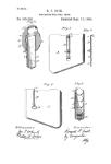
Now, in order to prevent the wear of the
bifurcated arm J against the inner surface of
the locking-ch amber, and also to provide suf- 85
ficient friction between those parts to maintain
the former in an elevated position in the act
of loading to overcome the momentum by rea-
son of sudden movements of the lever, I insert
a cork, K, between the two arms J2 J3, which 9c
has contact at each side of the chamber F.
If desired, other suitable yielding devices
may be substituted for the cork—as, for in-
stance, as shown in Fig. 6, two friction-caps,
K', of metal may be joined by a light spring, 95
K2, and inserted between said arms.
Having described my invention and its op-
eration, what I claim is—
1. In a magazine fire-arm, the combination
of a firing-bolt and a hammer with aleverpiv- ico
oted in the locking-chamber and adapted to
come in contact with the firing-bolt to recip-
rocate the same longitudinally, and with the
hammer to raise said hammer when swung on
its pivot, substantially as specified. 105
2. In a magazine fire-arm, the combination,
with a lever formed with a boss perforated and
surrounded by an annular groove, of a hoist-
ing-arm formed with an annular ring seated in
said recess and adapted to be raised by the le- 1Ю
ver, substantially as specified.
3. In a magazine fire arm, the combination,
with a pivoted lever formed with a perforated
boss and surrounded by an annular recess, of
a bifurcated hoisting-arm provided with a 115
ring seated in said recess and with cartridge-
hoisting and magazine spring-closing arms, —
substantially as specified.
4. In a magazine fire-arm, the combination
of a lever pivoted in the lock-plate thereof and 120
having bearing entirely across the same and
formed with shoulders at its forward end, with
a firing-bolt arranged above said lever and
provided with shouldersand recesses adapted
to be operated and locked in a firing position 125
by those on the lever, substantially asspecified.
5. In a magazine fire-arm, the combination
of a pivoted bifurcated hoisting-arm, of a cork
or equivalent inserted between said bifurca-
tions, and having frictional contact with the 13°
sides of the lock chamber, substantially as
specified.
6. In a magazine fire-arm, a firing bolt and
hammer, and an operating-lever provided with
373,410
cams or shoulders adapted to come into con-
tact with cams on the bolt and hammer,
whereby the former is retracted, returned, and
locked and the latter cocked, substantially as
5 specified.
7. In a magazine fire arm, a firing-bolt and
hammer provided with cams or shoulders, in
combination with a lever pivoted and carry-
ing a hoist, and provided with cams or shoul-
ro ders adapted to come in contact with those of
the bolt and hammer, whereby when the same
is swung forward the hammer is cocked, the
bolt retracted and the hoist elevated, and
when swung rearwardly the bolt is thrown for-
ts ward and the hoist lowered, the operation tak-
ing place in the order named, substantially as
specified.
8. The lever G, having boss G'2, perforated
as at G3, rounded by the annular recess G3, in
2o combination with the arm ,T, having the ring
J' seated in said recess and formed with the
curved hoisting-arms J3, and the resilient arms
J3, substantially as specified.
9. In a magazine fire-arm, and in combina-
tion with the barrel and magazine thereof, a 25
hoist-block having an integral spring-arm ar-
ranged below the same and mounted in rear of
said barrel and magazine to retain a cartridge
within the magazine when the block is ele-
vated and permit the insertion of cartridges 30
therein by compressing the said spring-arm
upwardly toward the block, substantially as
specified.
10. A hoist-block provided with a friction-
pad arranged to take bearing in the walls of 35
the lock-chamber, substantially as specified:
In testimony whereof I affix my signature in-
presence of two witnesses.
JOHN W. MULLINS.
Witnesses:
J. W. Jones,
M. 0. Webb.