/
Теги: weapons military affairs patent
Год: 1884
Текст
(No Model.)
R. F. COOK.
MAGAZINE FOR FIRE ARMS.
No. 305,050. Patented Sept. 16, 1884.
United States Patent Office.
BOSWELL F. COOK, OF ILION, NEW YORK, ASSIGNOR TO E. REMINGTON &
SONS, OF SAME PLACE.
MAGAZINE FOR FIRE-ARMS.
, SPECIFICATION forming part of Letters Patent No. 305,050, dated September 16, 1884.
Application filed June 11, 1884 (No model.)
To all whom it may concern:
Be it'known that I, Boswell F. Cook, of
Ilion, in the county of Herkimer and State of
New York, have invented certain Improve-
5 merits in Magazines for Fire-Arms, of which
the following is a specification.
My invention relates to magazines for fire-
arms; and the invention consists of a spring
slide or detent, combined with a magazine-box
io in such a manner as to retain or hold the car-
tridges in the box when the latter is detached
from the gun and release them when the maga-
zine is applied to the gun, as hereinafter more
fully set forth.
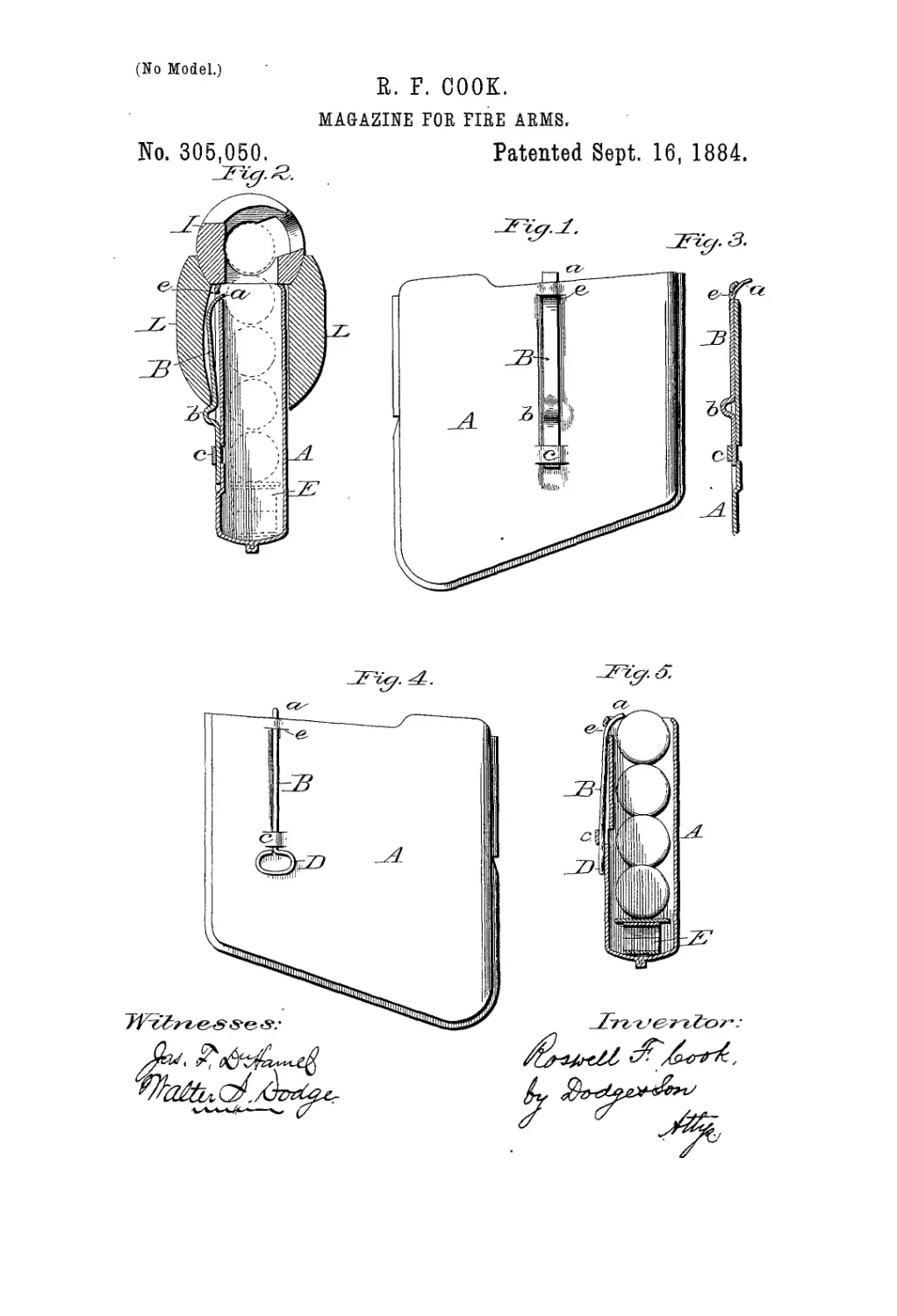
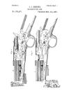
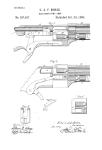
15 Figure 1 is a side elevation of the magazine
detached. Fig. 2 is a transverse vertical sec-
tion of the same in position as applied to the
gun. Fig. 3 is a vertical section of one side
of the magazine, showing the detent in posi-
20 tion to retain the cartridges; and Figs. 4 and
5 are side and sectional views of the magazine
or box, with its detent made of wire.
This magazine is designed for use in connec-
tion with the gun patented by J. P. Lee, No-
25 vember 4.1879, No. 221,328, in which the car-
tridges are fed from a magazine-box sidewise
and upward through an opening in the bottom
of the shoe of the gun, as indicated in Fig. 2;
and the object of the invention is to provide
30 the magazine with a detent or slide so con-
structed and applied that it will retain the car-
tridges in the box or magazine while the lat-
ter is disconnected from the gun, and will be
made to automatically release the cartridges
35 when the magazine is inserted in position for
use, and thus permit the cartridges to be fed
or forced from the magazine up into the gun.
To accomplish these results I construct the
box or magazine A of the form shown, and of
40 the proper size to contain the cartridges, which
are arranged lengthwise therein, one upon an-
other, as indicated, and as shown and de-
scribed in the patent hereinbefore referred to.
To one side of the box A,.I connect a spring
45 detent or retainer, B, as shown in Figs. 1, 2,
3, 4, and 5. This detent may be composed of
a flat strip of steel or similar spring metal, as
shown in Figs. 1, 2, and 3; or it may be made
of a piece of spring-wire, as shown in Figs. 4
50 and 5. In either case its upper end is bent
inward to form a lip, a, as shown in Figs. 2,
3, and 5, and this bent end is inserted through
a slit, e, cut in the side of the box near its up-
per edge, as shown, so that when the detent В
is shoved upward, as indicated in Figs. 1, 3, 55
and 5, its lip a will be projected inward over
the uppermost cartridge, as shown in Fig. 5,
thereby retaining or holding the cartridges in
the box against the pressure of the spring E
in the bottom of the box. The detent В has 60
its lower portion passed through a loop, c,
which is formed by cutting a couple of hori-
zontal slits in the wall of the box and pressing
the metal between the slits outward, as shown
clearly in Figs. 1 and 2, the wall of the box 65
being preferably indented, so as to form a ver-
tical recess or groove for the detent В to rest
and slide in, though this is not’absolutely es-
sential. The detent В is arranged to slide
freely up and down to a limited extent, as 70
shown in Figs. 2 and 3. .When shoved up, as
in Figs. 3 and 5, its lip or curved end a is pro-
jected inward over the cartridges, and prevents
them from rising; but when moved down, as
shown in Fig. 2, the curved end or lip is with- 75
drawn, thereby releasing the cartridges. In
order to operate the detent, so as to automati-
cally release the cartridges as the box is placed
in position, the detent is provided with a pro-
jection, b, as shown in Figs. 1, 2, and 3, which 80
is so located that it will strike against the un-
der side of the stock L of the gun as the box
is shoved into place, as shown in Fig. 2, there-
by shoving down the detent and withdrawing
its lip a, as' there shown. It is obvious that 85
this projection b maybe formed, as shown, by
bending the metal, or that it may be a pin or
stud secured to the detent B, so as to project
therefrom. So, too, it is obvious that, instead
of being arranged to strike against the lower go
edge of the stock or frame, it may be arranged
to strike against a projection or shoulder suit-
ably located within the opening in the stock
or gun-frame at any desired point, the only
requisite in that respect being that it shall 95
come in contact with something that will hold
it while the box A is shoved into its place, the
relative position of the shoulder b and the pro-
jection against which it strikes being such as
to cause the detent to slide far enough to with- 100
й
^05,050
5
ю
i5
20
25
30
draw its lip or curved end a from over the car-
tridges, and thus release them.
In Figs. 4 and 5 I have shown the detent В
made of spring-wire and without the shoulder
b. In this case the lower end of the detent is
bent around, so as to form a loop or handle,
D, by which it can be drawn down to release
the cartridges by hand after the box has been
shoved to its place; or, if desired, this loop D
can be arranged to strike against the under
side of the stock, or by locating it higher on
the side of the box it can be made to strike
against a shoulder or projection located with-
in the opening in the stock, and thus be made
to operate automatically, as may be preferred.
By this improvement the boxes can be filled
with cartridges and carried in a suitable box
or sack, ready for use whenever desired, and
all that is necessary is to shove the box into
place in connection with the gun, when the
cartridges will be automatically released and
be ready for use in the gun.
Having thus described my improvement,
what I claim is —
1. A cartridge box or magazine adapted to
contain a series of cartridges resting one upon
another, in combination with the sliding de-
tent B, having its upper end curved inward
to engage upon the cartridges and retain them
in the box when the detent is moved upward,
and to be retracted or withdrawn when the de-
tent is moved in the opposite direction.
2. In combination with the box A, the slid- '
ing detent B, provided with an inwardly-pro-
jecting end or lip, a, for engaging with and 35
retaining the cartridges in the box. and a pro-
jection, b, or equivalent device, for operating
the same, substantially as set forth.
3. In combination with the magazine or box
A, the sliding detent B, having its upper end 40
curved inward to project over and hold the
cartridges in the box, and provided with a
projection, b, or equivalent device, located in
relation to the gun stock or frame or a shoul-
der or projection therein in such position as to 45
be brought in contact therewith when the maga-
zine or box is shoved into place in the gun, and
thereby automatically release the cartridges
from the hold of said detent, substantially as
set forth. 50
4. The sliding detent B, having its curved
end inserted through a slot, e, in the side of
the box, near its top, and held in position by
the loop c on the side of the box below, sub-
stantially as shown and described.
ROSWELL F. COOK.
Witnesses: '
Thos. Richardson,
Fred H. Bennett.