/


Теги: weapons military affairs tanks
Год: 1942


Текст
ТМ 9-759
WAR DEPARTMENT
TECHNICAL MANUAL
MEDIUM TANK M l A3
AUGUST 4, 1942
ТМ 9-759
TECHNICAL MANUAL
No. 9-759
WAR DEPARTMENT
Washington, August 4, 1942
MEDIUM TANK M4A3
Prepared under the direction of
the Chief of Ordnance
(with the cooperation of the Ford Motor Company)
CONTENTS
Paragraphs Pages
Section I: Introduction ......................... 1-3 2
II: Description and tabulated data........ 4-5 3-7
III: Operating instructions and controls.. 6-11 8-22
IV: Lubrication .........................12-16 23-27
V: Inspections .........................17-22 28-33
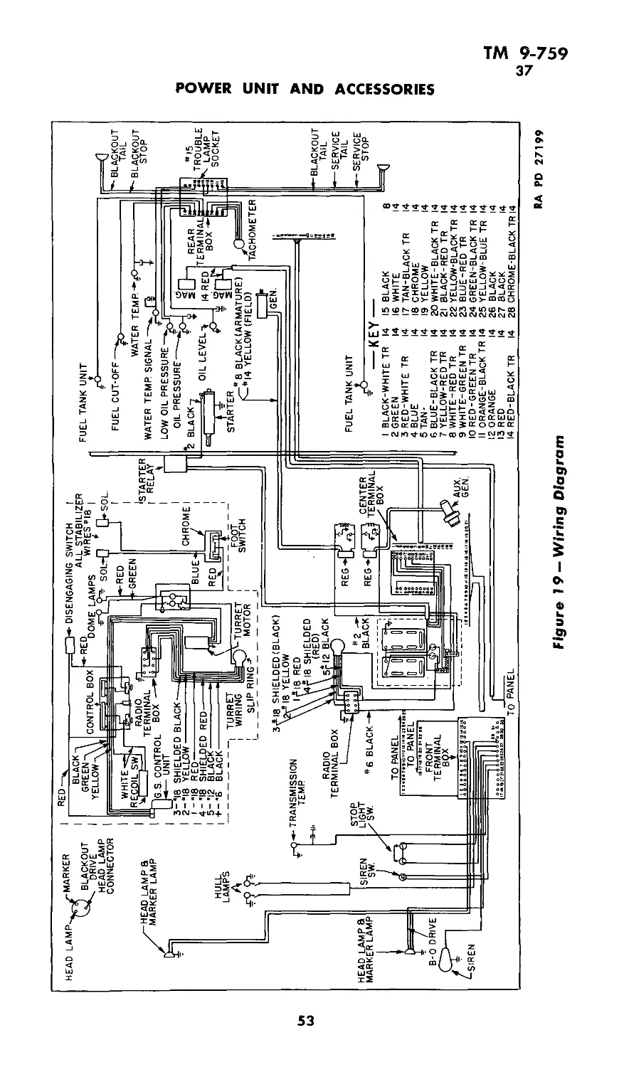
VI: Power unit and accessories________23-37 34-54
VII: References .........................38-40 55
Index ..................................................... 56-62
1
ТМ 9-759
1-3
MEDIUM TANK M4A3
Section I
INTRODUCTION
Paragraph
Purpose and scope ................................ 1
Content and arrangement of the manual................ 2
References........................................... 3
1. PURPOSE AND SCOPE.
TM 9-759 dated August 4, 1942, is intended to serve temporarily
(pending the publication of a revision now in preparation which will
be wider in scope) to give information and guidance to the personnel
of the using arms charged with the operation and maintenance of
this materiel.
2. CONTENT AND ARRANGEMENT OF THE MANUAL.
Sections I through V contain information chiefly for the guidance
of operating personnel. Section VI contains information intended
chiefly for the guidance of personnel doing maintenance work.
3. REFERENCES.
Section VII lists all Standard Nomenclature Lists, Technical
Manuals, and other publications for the material described herein.
2
TM 9-759
4-5
Section II
DESCRIPTION AND TABULATED DATA
Paragraph
Description ........................................... 4
Tabulated data......................................... 5
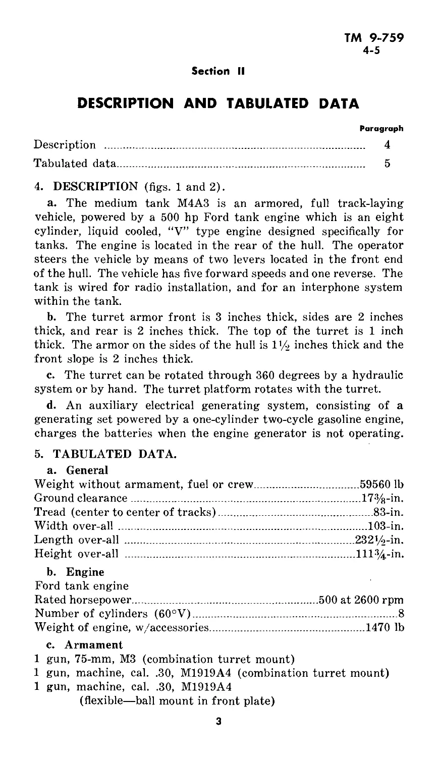
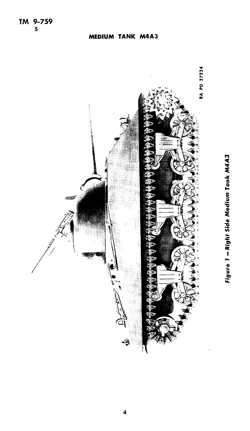
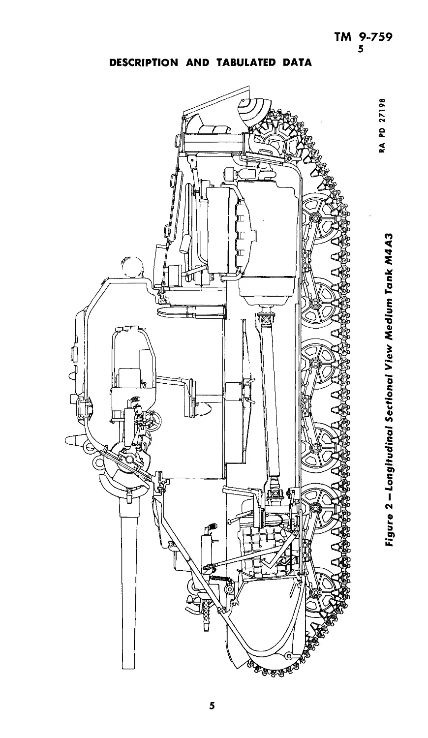
4. DESCRIPTION (figs. 1 and 2).
a. The medium tank M4A3 is an armored, full track-laying
vehicle, powered by a 500 hp Ford tank engine which is an eight
cylinder, liquid cooled, “V” type engine designed specifically for
tanks. The engine is located in the rear of the hull. The operator
steers the vehicle by means of two levers located in the front end
of the hull. The vehicle has five forward speeds and one reverse. The
tank is wired for radio installation, and for an interphone system
within the tank.
b. The turret armor front is 3 inches thick, sides are 2 inches
thick, and rear is 2 inches thick. The top of the turret is 1 inch
thick. The armor on the sides of the hull is I1/» inches thick and the
front slope is 2 inches thick.
c. The turret can be rotated through 360 degrees by a hydraulic
system or by hand. The turret platform rotates with the turret.
d. An auxiliary electrical generating system, consisting of a
generating set powered by a one-cylinder two-cycle gasoline engine,
charges the batteries when the engine generator is not operating.
5. TABULATED DATA.
a. General
Weight without armament, fuel or crew...................59560 lb
Ground clearance................................. 17%-'п-
Tread (center to center of tracks).................... 83-in.
Width over-all .................................... 103-in.
Length over-all .................................. 232^-in.
Height over-all .................................. 111%-in.
b. Engine
Ford tank engine
Rated horsepower________________________________500 at 2600 rpm
Number of cylinders (60°V).............................. 8
Weight of engine, w/accessories.........................1470 lb
c. Armament
1 gun, 75-mm, М3 (combination turret mount)
1 gun, machine, cal. .30, M1919A4 (combination turret mount)
1 gun, machine, cal. .30, M1919A4
(flexible—ball mount in front plate)
3
Figure 1 — Right Side Medium Tank M4A3
MEDIUM TANK M4A3
RA PD 27224
Figure 2 — Longitudinal Sectional View Medium Tank M4A3
RA PD 27198
Ul
>0
DESCRIPTION AND TABULATED DATA
ТМ 9-759
5
MEDIUM TANK M4A3
1 gun, machine, cal. .50 М2, H.B.
(flexible—race mount on turret hatch)
1 gun, submachine, cal. .45 Thompson, Model 1928A1
(carried on brackets within tank)
1 mount, tripod, machine gun, M1928A1, cal. .30 М2
d. Protected vision. Protected vision is provided for the driver
and crew by the use of steel shutters (open and shut type) at vision
slots, and by indirect vision devices called periscopes. There are five
periscopes on the M4A3 tank. The periscopes for the assistant driver
and the gunner are telescope equipped. The remaining three peri-
scopes are of the plain vision type.
e. Seats. Adjustable, padded, chair-type seats, equipped with
safety belts, are provided for driver, assistant driver, and gunner.
Round, padded seats, equipped with safety belts and of the snap
down type, are provided for the loader and tank commander.
f. Protective Padding. Parts of the interior are padded with
sponge rubber, to protect the tank crew from injury.
g. Communication
(1) Radio.........................
(2) Telephone ....................
h. Armor thickness
Hull, front slope...........2-in,
Rear ............. .....l(/9-in.
Sides ................ U/2-in.
Top .........................%-in.
SCR 245 sending and receiving
J Voice 15-25 miles
Code 30-45 miles
............... .Intra-tank
Bottom, front......... 1-in.
Bottom, rear ....:.....(A-in.
Turret, front....... ..3-in.
Sides and rear..........2-in.
Top ................ 1-in.
Rear ............... 2-in.
i. Turret. Cast armor plate................................... 360° traverse
j. Fuel and oil
Full capacity____________________
Number of miles without refueling
Octane rating of fuel_____________
Engine oil capacity...............
Lubricants........................
174 gal
Cross country 110 miles
^Highway 155 miles
......... ..80 or higher
............ ...32 qts
See Lubrication Chart
k. Performance
Maximum sustained speed on hard road................. 26 mph
Expected cross-country speeds for various terrains_4 to 26 mph
Maximum allowable engine speed.................. 2800 rpm
Minimum engine idling speed...................... 500 rpm
6
ТМ 9-759
5
DESCRIPTION AND TABULATED DATA
Maximum grade ascending ability.........................27°
Maximum grade descending ability........................27°
Maximum width of ditch tank will cross.............. 72-in.
Maximum vertical obstacle such as a wall, that the tank
will climb over............................ 18-in.
Maximum fording depth (at slowest forward speed)......36-in.
1. Crew.............................................5 men
m. Tracks.............................rubber block or steel
Track shoe width.............................. 16-in.
Track pitch ................................ 6-in.
7
ТМ 9-759
6
MEDIUM TANK M4A3
Section III
OPERATING INSTRUCTIONS AND CONTROLS
Paragraph
General information on controls........................... 6
Prestarting inspection................................ 7
Starting instructions ............................ 8
Engine test ................................... 9
Operating the vehicle...................................... 10
Stopping the engine................................ 11
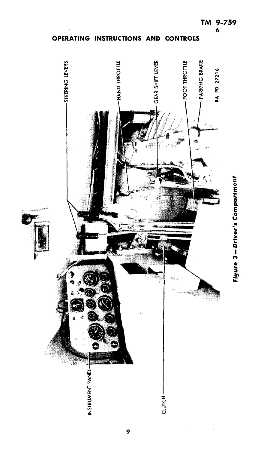
6. GENERAL INFORMATION ON CONTROLS (figs. 3 and 4).
a. Spark control. The spark control is entirely automatic and
requires no attention by the operator of the vehicle.
b. Throttle controls. A foot throttle pedal is located on the floor
in front of the driver’s seat, convenient to the driver’s right foot.
In conjunction with the foot pedal, a hand-operated throttle is pro-
vided, which is bracket mounted to the differential case above the
foot throttle.
c. Steering levers. Two steering levers are mounted on the floor
of the vehicle, in front of the driver’s seat. To steer the vehicle, pull
the steering lever on the side toward which it is desired to turn.
Pulling back either one of the levers slows down the track on that
side, while the the speed of the other track is increased. Thus the
vehicle turns with power on both tracks at all times (fig. 3).
d. Brakes.
(1) Service brakes. Pulling back simultaneously on both steering
levers slows down or stops the vehicle, depending on the effort
applied.
(2) Parking brake. The parking brake lever is located on the
right side of the driver, at rear of the transmission. It is a trans-
mission type brake, and should never be used for any purpose other
than parking. Always be sure parking brake is released before
moving the tank.
e. Clutch. The clutch pedal is located on the floor in front of
driver’s seat, convenient to the driver’s left foot. To permit shifting
of gears, the clutch is disengaged by depressing the clutch pedal.
f. Utility outlet. Two utility outlets are provided at the top of
the instrument panel that permit plugging in trouble light, wind-
shield wiper, etc.
g. Light switches. The knob on the instrument panel marked
“LIGHTS” controls the service lights and the blackout driving
8
CLUTCH
STEERING LEVERS
HAND THROTTLE
FOOT THROTTLE
PARKING BRAKE
RA PD 27216
Figure 3 —Driver's Compartment
INSTRUMENT PANEL
- GEAR SHIFT LEVER
OPERATING INSTRUCTIONS AND CONTROLS
О о
tn
>0
о
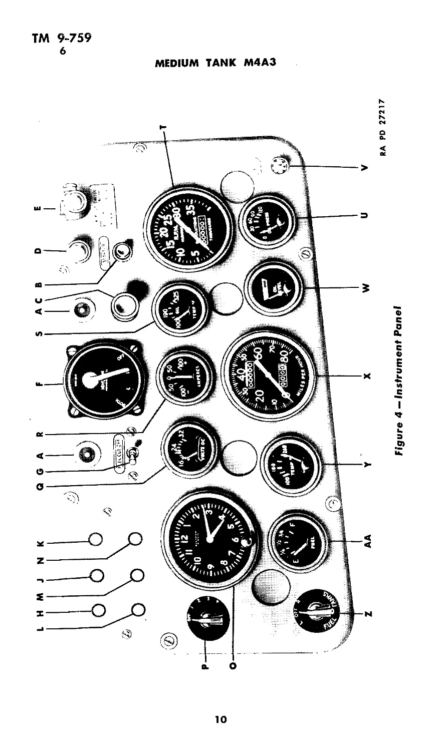
Figure 4 — Instrument Panel
2
о мэ
MEDIUM TANK M4A3
RA PD 27217
(Л
<©
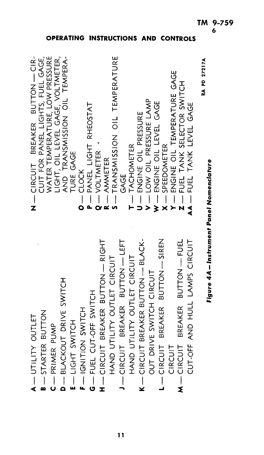
A—UTILITY OUTLET
B —STARTER BUTTON
C — PRIMER PUMP
D —BLACKOUT DRIVE SWITCH
E—LIGHT SWITCH
F—IGNITION SWITCH
G—FUEL CUT-OFF SWITCH
H —CIRCUIT BREAKER BUTTON —RIGHT
HAND UTILITY OUTLET CIRCUIT
J —CIRCUIT BREAKER BUTTON — LEFT
HAND UTILITY OUTLET CIRCUIT
K —CIRCUIT BREAKER BUTTON — BLACK-
OUT DRIVE SWITCH CIRCUIT
L — CIRCUIT BREAKER BUTTON —SIREN
CIRCUIT
M — CIRCUIT BREAKER BUTTON — FUEL
CUT-OFF AND HULL LAMPS CIRCUIT
Figure 4A — Instrument
N — CIRCUIT BREAKER BUTTON —CIR-
CUIT FOR PANEL LIGHTS, FUEL GAGE,
WATER TEMPERATURE, LOW PRESSURE
LIGHT, OIL LEVEL GAGE, VOLTMETER,
AND TRANSMISSION OIL TEMPERA-
TURE GAGE
O—CLOCK
P—PANEL LIGHT RHEOSTAT
Q_ VOLTMETER -
R _ AMMETER
S —TRANSMISSION OIL TEMPERATURE
GAGE
T —TACHOMETER
U—ENGINE OIL PRESSURE
V—LOW OIL PRESSURE LAMP
W—ENGINE OIL LEVEL GAGE
X — SPEEDOMETER
Y — ENGINE OIL TEMPERATURE GAGE
Z — FUEL TANK SELECTOR SWITCH
AA—FUEL TANK LEVEL GAGE
RA PD 27217A
□ el Nomenclature
OPERATING INSTRUCTIONS AND CONTROLS
Ui
<©
ТМ 9-759
6
MEDIUM TANK M4A3
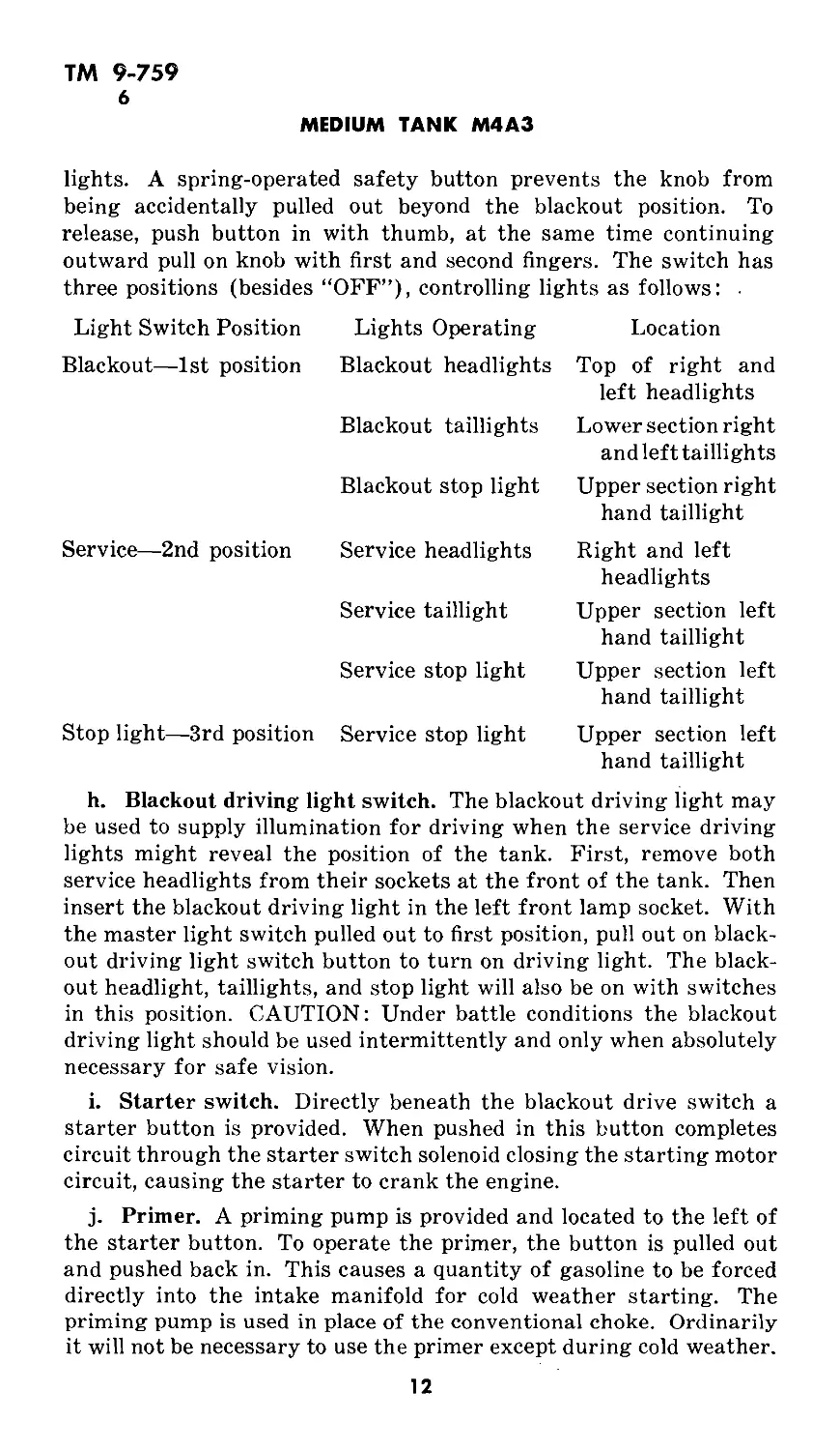
lights. A spring-operated safety button prevents the knob from
being accidentally pulled out beyond the blackout position. To
release, push button in with thumb, at the same time continuing
outward pull on knob with first and second fingers. The switch has
three positions (besides “OFF”), controlling lights as follows: •
Light Switch Position Lights Operating Location
Blackout—1st position Blackout headlights Top of right and left headlights
Blackout taillights Lower section right and left taillights
Blackout stop light Upper section right hand taillight
Service—2nd position Service headlights Right and left headlights
Service taillight Upper section left hand taillight
Service stop light Upper section left hand taillight
Stop light—3rd position Service stop light Upper section left hand taillight
h. Blackout driving light switch. The blackout driving light may
be used to supply illumination for driving when the service driving
lights might reveal the position of the tank. First, remove both
service headlights from their sockets at the front of the tank. Then
insert the blackout driving light in the left front lamp socket. With
the master light switch pulled out to first position, pull out on black-
out driving light switch button to turn on driving light. The black-
out headlight, taillights, and stop light will also be on with switches
in this position. CAUTION: Under battle conditions the blackout
driving light should be used intermittently and only when absolutely
necessary for safe vision.
i. Starter switch. Directly beneath the blackout drive switch a
starter button is provided. When pushed in this button completes
circuit through the starter switch solenoid closing the starting motor
circuit, causing the starter to crank the engine.
j. Primer. A priming pump is provided and located to the left of
the starter button. To operate the primer, the button is pulled out
and pushed back in. This causes a quantity of gasoline to be forced
directly into the intake manifold for cold weather starting. The
priming pump is used in place of the conventional choke. Ordinarily
it will not be necessary to use the primer except during cold weather.
12
ТМ 9-759
6
OPERATING INSTRUCTIONS AND CONTROLS
Excessive priming of the engine will- cause flooding and failure to
start, and the excess gasoline will wash the oil from the cylinder
walls with the result that the cylinder will not be properly lubricated
until the engine oil starts circulating.
k. Ignition switch. The Ford tank engine uses two 4-cylinder
Bosch magnetos which are controlled by a 4-position switch in the
center of the instrument panel at the top. When the switch lever is
to the left, both magnetos are on. When the switch lever is at the
position marked “L” the left hand magneto only is on, and the engine
would be running on the left hand four cylinders. Left or right are
used with reference to the engine as viewed from the rear of the
tank. When the ignition switch lever is at the position marked “R”
the right hand magneto is on and the engine will run on the four
cylinders on the right hand bank only.
1. Fuel cut-out. To the left of the ignition switch a spring loaded
toggle switch is provided which operates the carburetor degasser
electrically. When stopping the engine always pull this toggle
switch to the right and hold in this position until the engine stops
before turning off the ignition. This shuts off the fuel from the idle
fuel supply wells in the carburetor. This will prevent loading up of
the carburetor in case the engine is to be restarted while still hot.
m. Circuit breakers. Six circuit breaker buttons are provided in
the upper left hand corner of the instrument panel, which control
the six circuit breakers which take the place of the conventional
fuses. In each instance when these circuits are overloaded, the
circuit breaker will open. The circuit involved is then closed merely
by pressing the correct button. The circuits controlled by these six
buttons are as follows (fig. 4):
(h) Right hand utility outlet circuit
(j) Left hand utility outlet circuit
(k) Blackout drive switch circuit
(1) Siren circuit
(m) Fuel cut-off and hull lamps circuits
(n) Circuit for panel lights, fuel gage, water temperature, low
pressure light, oil level gage, voltmeter, and transmission oil tem-
perature gage.
n. Clock. Directly beneath the six circuit breaker buttons an
8-day clock is provided. A reset and rewinding knob is located at the
bottom of the dial.
o. Compartment light rheostat. To the left of the clock a 5-posi-
tion rheostat is provided which controls the brilliance of the panel
lights.
13
ТМ 9-759
6
MEDIUM TANK M4A3
p. Voltmeter. To the right of the clock a voltmeter having a
range from 16 to 32 volts is provided. When the battery master
switch is off, the voltmeter will read at the lower end of the scale.
When the master switch is “on,” the voltmeter should read battery
voltage (approximately 24 volts). If reading is low with the engine
not running and no electrical energy is being used, the batteries are
low in charge and should be recharged. At normal operating speeds
during normal ambient temperatures, the voltage should not exceed
30 volts. If the reading is greater than this, the generator regulator
is not properly limiting the voltage, and should be replaced; other-
wise the generator will burn out. This voltmeter likewise reads while
the auxiliary generating unit is charging the battery, at which time
the voltage should not exceed 30 volts.
q. Ammeter. To the right of the voltmeter an ammeter is pro-
vided with a range of 100 ampere discharge to 100 ampere charge.
If during normal operation when little current is being used, the
ammeter consistently indicates discharge either the generator regu-
lator is not functioning properly or the generator itself is at fault.
In either case the battery is not being charged and will quickly dis-
charge. These units should receive immediate attention to prevent
failure during operation. Even with no electrical energy being used
the ammeter should never go above 50 amperes (plus or charge)
(100 amperes on tanks having two generators). If the ammeter
indicates more than 50 ampere charge, (100 amperes on tanks hav-
ing two generators) the current limiting unit in the generator regu-
lator is at fault and the regulator should be replaced; otherwise the
generator will burn out during operation.
r. Oil temperature gage. To the right of the ammeter an oil
temperature gage having a range of from 100 to 325 degrees indi-
cates the temperature of the oil in the transmission.
s. Tachometer. The tachometer is located on the right hand side
of the instrument panel to the left of the transmission oil tempera-
ture gage. The throttle stop screw on the carburetor should be so
adjusted that the engine should idle at 500 rpm after warm-up.
The maximum speed of the engine is governed by a flyball type
governor located at the rear of the right hand cylinder head. This
governor is set to limit the engine speed to 2650 rpm under full load
with wide open throttle (10-inch vacuum). If during operation
under full load it is possible to run the engine at speeds above 2650
rpm, or if the governor limits the speed at some point below 2650
rpm, the ordnance maintenance personnel will be notified. If the
governor is set too low it will be impossible to get maximum speed
and power from the vehicle; on the other hand if the governor is set
too high, damage to the engine and other working parts could result.
14
ТМ 9-759
6
OPERATING INSTRUCTIONS AND CONTROLS
t. Oil pressure gage. An engine oil pressure gage is located
directly beneath the tachometer. At normal temperatures the oil
pressure should be between 60 and 80 pounds. If during operation
the oil pressure suddenly drops off, immediately stop the engine.
This fault may be due to low oil level. If oil pressure drops off slowly,
it may be due to a change in the viscosity of the oil due to overheat-
ing. Check engine temperature.
u. Low oil pressure signals. To the right of the oil pressure gage
a red jewel type light is provided that signals the driver when the
oil pressure drops below eight pounds.
v. Oil level gage. An oil level gage located between the speedom-
eter and the oil pressure gage indicates whether sufficient oil is
carried in the oil pan sump. As long as the oil level gage is in the
green sector, the oil level is satisfactory. When the reading drops
to the red sector, oil should be added to bring the reading up to the
right hand side of the green sector.
w. Speedometer. The speedometer is located in the center of the
instrument panel at the bottom, and is equipped with a trip mileage
reset at the bottom of the instrument panel.
x. Engine temperature gage. The engine temperature gage is
located to the left of the speedometer and is calibrated from 100 to
260 degrees. The cooling system on the M4A3 tank is sealed and not
Open to atmospheric pressure, with the result that boiling point of
the coolant and consequently overheating actually does not occur
until a temperature of approximately 230 degrees is reached. In
normal operation under maximum power on a level hard surface
the engine temperature should not be greater than 90 degrees above
atmospheric temperature.
y. Fuel level gage and selector switch. In the lower left hand
corner of the instrument panel a selector switch and fuel level gage,
permit the checking of the fuel level in the two sponson fuel tanks.
The selector switch has three positions “L” (left), “Off,” and “R”
(right). With the selector switch in the “Off” position the fuel level
gage will read “E” (empty). With the selector switch in the left
position the fuel level gage will indicate the level of the fuel in the
left hand sponson tank. With the selector switch in the “R” position
the fuel level gage will indicate the level of the fuel in the right hand
sponson tank.
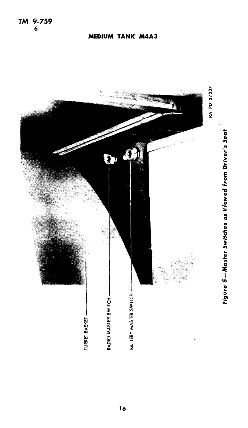
z. Battery master switch (fig. 5). A battery master switch is
located approximately 30 inches to the rear of the driver’s seat and
underneath the turret basket floor. To open or close this switch, it
is necessary to raise the knob approximately '/«-inch and turn.
When this switch is open all electrical power is shut off at the battery
15
TURRET BASKET
RADIO MASTER SWITCH
BATTERY MASTER SWITCH
Figure 5 — Master Switches as Viewed from Driver’s Seat
<©
(Л
<©
RA PD 27237
MEDIUM TANK M4A3
TM 9-759
6
OPERATING INSTRUCTIONS AND
CONTROLS
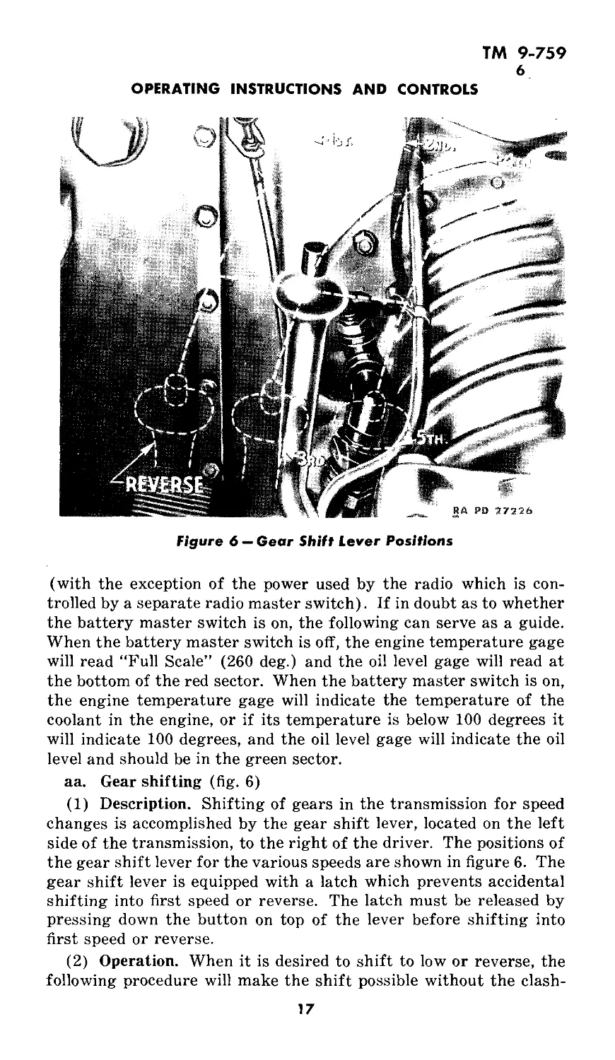
Figure 6 — Gear Shift Lever Positions
(with the exception of the power used by the radio which is con-
trolled by a separate radio master switch). If in doubt as to whether
the battery master switch is on, the following can serve as a guide.
When the battery master switch is off, the engine temperature gage
will read “Full Scale” (260 deg.) and the oil level gage will read at
the bottom of the red sector. When the battery master switch is on,
the engine temperature gage will indicate the temperature of the
coolant in the engine, or if its temperature is below 100 degrees it
will indicate 100 degrees, and the oil level gage will indicate the oil
level and should be in the green sector.
aa. Gear shifting (fig. 6)
(1) Description. Shifting of gears in the transmission for speed
changes is accomplished by the gear shift lever, located on the left
side of the transmission, to the right of the driver. The positions of
the gear shift lever for the various speeds are shown in figure 6. The
gear shift lever is equipped with a latch which prevents accidental
shifting into first speed or reverse. The latch must be released by
pressing down the button on top of the lever before shifting into
first speed or reverse.
(2) Operation. When it is desired to shift to low or reverse, the
following procedure will make the shift possible without the clash-
17
ТМ 9-759
6-9
MEDIUM TANK M4A3
ing of gears which usually results. From neutral move the gear
shift lever as though to shift into third gear. Maintain pressure in
this direction long enough to stop the propeller shaft and then, with
the clutch still held out, shift smartly into low or reverse. If when
shifting to any of the higher speeds there is a raking of gears, go
back to neutral and, still holding the clutch out, start the shift over.
Do not attempt to complete a shift that begins with a clashing of
gear teeth.
7. PRESTARTING INSPECTION.
Before the engine is started follow procedure outlined under pre-
starting inspection in Section V.
8. STARTING INSTRUCTIONS.
Before attempting to start the engine, familiarize yourself with
all of the various instruments and controls, as outlined in para-
graph 6; make sure that the function of each control is thoroughly
understood and that the significance of the readings on the various
instruments is appreciated.
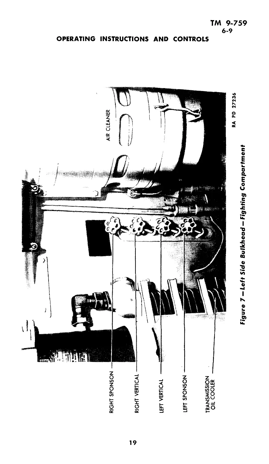
a. Open gasoline shut-off valves which are located in the left
side of the fighting compartment (fig. 7). If the fuel tanks are full,
run from right tanks for 30 minutes to provide expansion space for
the fuel before opening valves on left fuel tank.
b. Close battery master switch.
c. Put gear shift lever in neutral.
d. Pull hand throttle out about %-inch.
e. In cold weather prime the engine three to nine quick pulls on
the primer, depending on outside temperature.
f. Depress clutch pedal.
g. Turn magneto switch to “both” position.
h. Press starter button.
i. Engine should start readily.
9. ENGINE TEST.
a. As soon as the engine starts, check oil pressure. Stop engine
if the oil pressure is not indicated in 30 seconds.
b. Check the operation of instruments and switches while the
engine is idling. Idle engine until engine temperature gage reads
above 100 degrees.
c. When engine is sufficiently warm set hand throttle to 800 rpm.
Run the engine on each magneto and compare each tachometer read-
ing with the reading when both magnetos were used. When either
magneto shows a drop to less than 400 rpm, the cause should be
investigated.
18
«о
AIR CLEANER
RIGHT SPONSON
RIGHT VERTICAL
LEET VERTICAL
LEFT SPONSON
TRANSMISSION
OIL COOLER
RA PD 27236
Figure 7 — Left Side Bulkhead — Fighting Compartment
OPERATING INSTRUCTIONS AND CONTROLS
2
О
Ui
>0
ТМ 9-759
9-10
MEDIUM TANK M4A3
d. Push hand throttle in. (Carburetor stop screws should be set
to idle the engine at 500 rpm after warming up.) Never idle the
engine at less than 500 rpm.
e. Never lug engine below 1000 rpm at wide open throttle. Shift
to a lower gear.
f. Check oil pressure and temperature frequently.
10. OPERATING THE VEHICLE.
Before attempting to drive the vehicle the prospective driver
should be thoroughly familiar with all the instruments and the
significance of their readings. One must also know the function
and operation of the controls in the compartment. Review of para-
graph 5 will be helpful. The limitations of vehicle and engine are
covered under paragraph 4;
a. Operating instructions. With the driver in the driver’s seat,
the engine at idling speed, and all instruments showing normal read-
ings, the driver may now operate the vehicle.
(1) Release the parking brake. This is important.
(2) Disengage the clutch by pressing clutch pedal down to the
floor and holding it down.
(3) Move the gear shift lever into second gear, for normal opera-
tion. First gear will be used only when shifting vehicle in buildings
or over obstacles.
(4) Gradually release the clutch pedal, at the same time depress-
ing the foot throttle. Except when under fire, do not move the
vehicle in or out of close quarters without the aid of personnel out-
side of the vehicle serving as a guide.
(5) When the vehicle has started and is moving with engine
speed of 1200 rpm, release the foot throttle, depress the clutch
again, and move the gear shift lever into the third gear position.
Release the clutch and again depress the throttle to pick up the
load of the vehicle.
(6) Repeat the above procedure until the highest gear is reached
which will enable the vehicle to proceed at the desired speed without
causing the engine to labor. Do not ride the clutch. The driver’s
left foot must be completely removed from the clutch pedal while
driving, to avoid unnecessary wear and burning out the clutch.
(7) To place the vehicle in reverse gear a complete stop must be
made, the throttle closed until the tachometer reads 500 rpm (lowest
idling speed). Depress the clutch pedal and move the gear shift
lever to the reverse position (fig. 6). Backing the vehicle should
never be attempted unless an observer is stationed in front to guide
the driver.
20
ТМ 9-759
10
OPERATING INSTRUCTIONS AND CONTROLS
(8) To steer the vehicle pull back the right hand steering lever
to make a right turn or the left hand lever for a left turn. This
action brakes the track on the inside of the turn and speeds up the
outside track. The driver should anticipate each turn and be ready
to apply more power as it is needed to compensate for the braking
effort. The hands should be, free of the steering lever when not
actually steering the tank.
(9) To stop the vehicle, release the throttle and pull back on
both steering levers at the same time. Depress the clutch pedal
when the vehicle has slowed down to approximately two to five miles
per hour, depending upon which gear is being employed before stop-
ping. Set the hand throttle for a tachometer reading of 500 rpm
for the duration of the halt.
(10) The tachometer, the oil temperature gage, and the oil
pressure gage give the most satisfactory indications of the engine’s
performance. Should the indications of any of these instruments
appear to be irregular, the engine should be stopped, and the cause
investigated.
b. Towing instructions:
(1) Equipment. A towing shackle is mounted on each corner of
the hull of the vehicle about 20 inches from the ground. Two of
these shackles are mounted in front and two in the rear. These
shackles provide a quick method of attaching either the “towing
bar” or cables.
(2) Precautions. If there are tracks on the vehicle to be towed,
always disconnect the propeller shaft at the transmission companion
flange and leave the vehicle in fifth gear. This procedure insures
adequate circulation of the transmission oil while the vehicle is in
motion. If the tracks are removed before towing the vehicle, this
precaution is not necessary. In towing there are several precautions
that the driver must take to avoid trouble or unnecessary delay.
Changes of direction are always to be made by a series of slight
turns so that the vehicle being towed is as nearly as possible directly
behind the one doing the towing or “tracking.” This will prevent
the cable from contacting the track, which might ruin both the cable
and the track blocks. Soft muddy ground is to be avoided, since the
tracks may slip on such a surface. If it is necessary to cross a muddy
area, the driver should be careful to straighten out both vehicles
before entering it, as it is more difficult to pull a tank at an angle
than when following in tow. Grousers may be installed as required.
The maximum speed when towing should be not more than 12 miles
per hour and then only with an operator for steering and braking
the towed vehicle. NOTE: Except in cases where a “short hitch”
21
ТМ 9-759
10-11
MEDIUM TANK M4A3
is absolutely necessary a towing cable will not be coupled to another
vehicle by other than the thimbled eyes provided at both ends.
Doubling the cable causes sharp bends in the wire rope which will
cause rapid failure of the strands and will leave the cable extremely
dangerous to handle. When a “short hitch” is desired, the two eyes
of the cable are attached to the towing vehicle. The cable with
leads crossed, is then passed through both shackles of the towed
vehicle. This provides an arrangement having a minimum of bend-
ing action and movement at the shackles, and furnishes clearance
between cable and tracks.
(3) Method. If no operator is available to steer the disabled
vehicle one cable will facilitate tracking of the towed vehicle. Care
must be taken on turning, not to get the cable tangled up with the
track of either vehicle.
11. STOPPING THE ENGINE.
After completing a run, the engine must be allowed to operate at
500 rpm for two minutes to assure a gradual and uniform cooling
of the valves and other various engine parts.
22
ТМ 9-759
12-16
Section IV
LUBRICATION
Paragraph
General................................................. 12
Lubrication guide................................. 13
Points to be lubricated by ordnance maintenance personnel.... 14
Reports and records................................. 15
Lubrication guide notes............................... 16
12. GENERAL.
The following lubrication instructions for medium tank M4A3 are
published for the information and guidance of all concerned, and
supersede all previous instructions. Materiel must be lubricated
in accordance with the latest instructions contained in Technical
Manuals and/or Ordnance Field Service Bulletins.
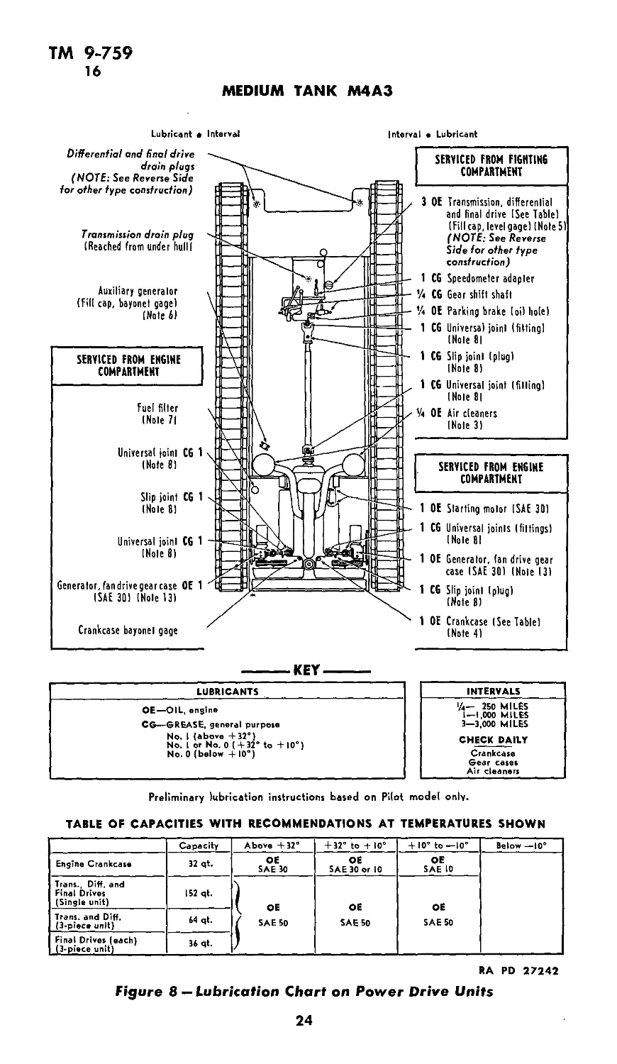
13. LUBRICATION GUIDE (figs. 8 and 9).
Lubrication instructions for all points to be serviced are shown
in War Department Lubrication Guide No. 104, which specifies the
types of lubricants required and the intervals at which they are
to be applied. The following lubrication instructions contain the
same information as the guide. Guides from which data are repro-
duced are 10x15 in. laminated charts which are part of the accessory
equipment of each piece of materiel.
14. POINTS TO BE LUBRICATED BY ORDNANCE MAINTE-
NANCE PERSONNEL.
Generators. Remove and repack generator bearings with
GREASE, ball and roller bearing, once each year.
15. REPORTS AND RECORDS.
a. Reports. If lubrication instructions are closely followed, proper
lubricants used, and satisfactory results are not obtained, a report
will be made to the ordnance officer responsible for the maintenance
of the materiel.
b. Records. A complete record of lubrication servicing will be
kept for the materiel.
16. LUBRICATION GUIDE NOTES.
Additional lubrication and service instructions on individual units
and parts:
1. FITTINGS — Clean before applying lubricant. Lubricate bogie
wheels, idler and track support rollers, tachometer and speedometer
23
ТМ 9-759
16
MEDIUM TANK M4A3
Lubricant • Interval
Interval a Lubricant
Differential and final drive
drain plugs
(NOTE: See Reverse Side
for other type construction)
Transmission drain plug
(Reached from under hull I
Auxiliary generalor
(Fill cap, bayonet gagel
(Note 6)
SERVICED FROM ENGINE
COMPARTMENT
Fuel filler
INole 71
Universal joint CG 1
INote SI
Slip joint CG 1
INole 8)
Universal joint CG 1
INole 8)
Generator, fan drive gear case OE 1
ISAE 301 INole 131
Crankcase bayonet gage
SERVICED FROM FIGHTING
COMPARTMENT
3 OE Transmission, differential and final drive (See Table) (Fill cap, level gage) I Note 5) (NOTE: See Reverse Side for other type construction)
1 CG Speedometer adapter
CG Gear shift shaft
’/4 OE Parking brake loi) hole)
1 CG Universal joint (fitting) (Note 81
1 CG Slip joint (plug) (Note 8)
1 CG Universal joint (filling) INole 81
’/4 OE Air cleaners INole 3)
SERVICED FROM ENGINE
COMPARTMENT
1 OE Starling motor ISAE 30)
1 CG Universal joints I fittings)
INole 81
1 OE Generalor, fan drive gear
case ISAE 30) INole 13)
1 CG Slip joint (plug)
(Note 8)
1 OE Crankcase (See Table)
INole 4)
KEY
LUBRICANTS
OE—OIL, engine
CG—GREASE, general purpose
No. I (above +32°)
No. I or No. О ( + 32° to +10°)
No. 0 (below + 10°)
INTERVALS
i/4— 250 MILES
1—1,000 MILES
3—3,000 MILES
CHECK DAILY
Crankcase
Gear cases
Air cleaners
Preliminary lubrication instructions based on Pilot model only.
TABLE OF CAPACITIES WITH RECOMMENDATIONS AT TEMPERATURES SHOWN
Capacity Above +32d + 32° to + 10° + 10° to —10° Below —10°
Engine Crankcase 32 qt. OE SAE 30 OE SAE 30 or 10 OE SAE 10
Trans., Diff. and Final Drives (Single unit) 152 qt. OE j* SAE 50 OE SAE 50 OE SAE 50
Trans, and Diff. (3-piece unit) 64 qt.
Final Drives (each) (3-piece unit) 36 qt.
RA PD 27242
Figure 8 — Lubrication Chart on Power Drive Units
24
TM 9-759
16
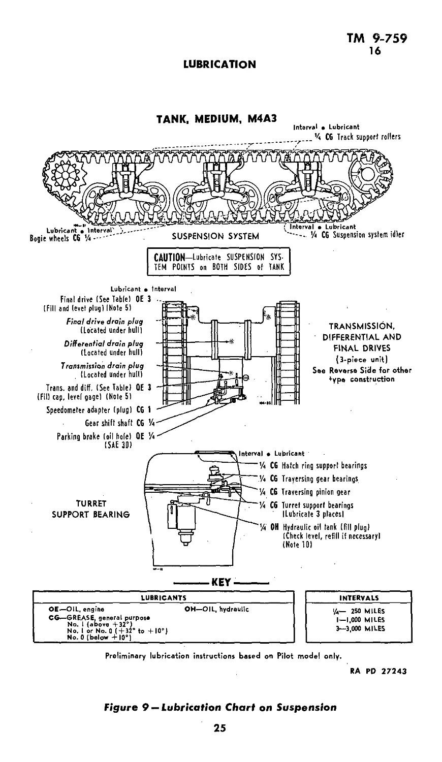
LUBRICATION
TANK, MEDIUM, M4A3
Interval • Lubricant
CAUTION—Lubricate SUSPENSION SYS-
TEM POINTS on BOTH SIDES of TANK
Lubricant • Interval
Final drive (See Table) OE
(Fill and level plug) I Note 5)
Final drive drain plug
(Located under hull)
Differential drain plug
(located under hull)
Transmission drain plug
(Located under hull)
Trans, and diff. (See Table) OE
(Fil) cap, level gage) (Note S)
Speedometer adapter (plug) CG
Gear shift shaft CG
Parking brake (oil hole) OE
(SAE 30)
TRANSMISSION,
DIFFERENTIAL AND
FINAL DRIVES
(3-piece unit)
See Reverse Side for other
*ype construction
TURRET
SUPPORT BEARING
> Lubricant
CG Hatch ring support bearings
CG Traversing gear bearings
C6 Traversing pinion gear
CG Turret support bearings
(Lubricate 3 places!
OH Hydraulic oil tank (fill plug)
(Check level, refill if necessary!
(Note 10)
------KEY-------
LUBRICANTS
OE—OIL, engine OH—OIL, hydraulic
CG—GREASE, general purpose
No. 1 (above +32°)
No. I or No. 0 (+32° to +10°)
No. 0 (below + 10°)
INTERVALS
l/a— 250 MILES
1—1,000 MILES
3—3,000 MILES
Preliminary lubrication instructions based on Pilot model only,
RA RD 27243
Figure 9 — Lubrication Chart on Suspension
25
ТМ 9-759
16
MEDIUM TANK M4A3
adapters until grease overflows relief valve. Lubricate other fittings
until new grease is forced from the bearing, unless otherwise speci-
fied. CAUTION: Lubricate suspension points after washing tank.
2. INTERVALS — The intervals indicated at points on Lubrica-
tion Guide are for normal service. For extreme conditions of speed,
heat, water, mud, snow, rough roads, dust, etc., reduce interval on
guide by 1/3 or y2, or more if conditions warrant.
3. AIR CLEANERS — Proper maintenance of air cleaners is
essential to prolonged engine life. Drain, clean and refill with OIL,
engine, crankcase grade, daily, when operating on dirt roads or cross
country; every 250 miles when operating on paved roads or during
wet weather. Depending on operating conditions, remove air clean-
ers and wash all parts every 100 to 500 miles. Inspect air outlet
rubber hose connections for leaks and make sure pipes are in aline-
ment. Replace connections if there is evidence of wear or deteriora-
tion. CAUTION: Keep all air pipe connections tight.
4. CRANKCASE — Check oil level daily, add oil if necessary.
Drain every 500 miles or 50 hours when operating on dirt roads or
cross country; every 1000 miles when operating on paved roads or
during wet weather. Drain only when engine is hot. Refill to FULL
mark on bayonet gage, located on rear of engine on left side. Run
engine a few minutes and recheck level. CAUTION: Be sure pres-
sure gage indicates oil is circulating.
5. GEAR CASES — On some assemblies, the transmission, dif-
ferential and final drives are combined in one unit. These are filled
through transmission filler only and drained through transmission
and final drive drain plug holes. Other assemblies use 3-piece units,
filled through transmission filler and each final drive filler plug hole
and drained through transmission, differential and final drive drain
plug holes. Check level daily, add oil if necessary. Check with tank
on level ground. Make visual inspection for leakage weekly. Report
leakage to ordnance maintenance personnel. Drain, flush and refill
at end of first 250 miles; thereafter as indicated at points on Lubri-
cation Guide. When draining, drain immediately after operation.
To flush cases, fill to proper level with OIL, engine, SAE 10. Operate
tank slowly in low gear for several minutes and redrain. Fill gear
cases with OIL, engine, grade specified in table of capacities and
recommendations. CAUTION: Fill single piece unit to mark on
bayonet gage with fill cap resting on top of fill pipe. Fill 3-piece
unit to 1 inch below final drive fill plug holes and to mark on trans-
mission bayonet gage. Clean transmission filler strainer every 3000
miles. CAUTION: Do not remove strainer when filling.
6. AUXILIARY GENERATOR — Two-cycled air cooled engine,
mounted on turret floor, rear, is lubricated by OIL, engine, with fuel.
26
ТМ 9-759
16
LUBRICATION
Mix thoroughly % pint OIL, engine, SAE 30, with each gallon of
gasoline before pouring into tank. CAUTION: Do not pour gasoline
and oil separately into tank. Keep fuel strainer clean. Magneto —
Every 200 hours, lubricate magneto cam follower by oiling felt with
one or two drops OIL, engine, SAE 30.
7. FUEL FILTER — Open drain cock daily to remove sediment
and water. Every 1000 miles, remove element and wash in fuel or
SOLVENT, dry-cleaning.
8. UNIVERSAL JOINTS AND SLIP JOINT — Remove tunnel
shield sections over universal joints and slip joint at ends of tunnel
shield. Lubricate universal joints through fittings with GREASE,
general purpose, seasonal grade, until grease overflows at relief
valve. To lubricate slip joint, remove plug and insert fitting. Apply
GREASE, general purpose, seasonal grade, until grease is forced
from end of spline. CAUTION: After lubricating, remove fitting
and replace plug.
9. OIL FILTER — The oil filter is of the self-turning type and
is located in the engine crankcase. Remove filter from crankcase
every 1000 miles, drain sediment from housing and reinstall.
10. HYDRAULIC OIL TANK — Located on side of turret. Check
level every 250 miles by means of glass level gage. Add OIL, hy-
draulic, if necessary. Drain, flush and refill every six months.
Capacity 12 quarts.
11. OIL CAN POINTS — Lubricate machine gun mount ball
socket, door and shield hinges, peep hole protector slides, door
latches, lever bushings, control rod pins and clevises with OIL,
engine, SAE 30, every 250 miles.
12. POINTS REQUIRING NO LUBRICATION — Water pump,
clutch pilot bearing, clutch yoke bearing, clutch release bearing,
fan hubs, bogie wheel suspension linkage, final drive sprocket
bearings.
27
ТМ 9-759
17-18
MEDIUM TANK M4A3
Section V
INSPECTIONS
Paragraph
Purpose ....................................... 17
Prestarting inspection ............ -.......-....-...... 18
Inspection during operation.............................. 19
Inspection at the halt................................... 20
Inspection after operation............................... 21
Periodic inspection .................................... 22
17. PURPOSE.
a. To insure mechanical efficiency, it is necessary that tanks be
systematically inspected at intervals in order' that defects may be
discovered and corrected before they result in serious damage.
b. Cracks that develop in castings or other metal parts may often
be detected through the medium of dust and oil deposits upon the
completion of the run.
c. Suggestions toward changes in design prompted by chronic
failure or malfunction of a unit or group of units; pertinent changes
in inspection or maintenance methods; and changes involving safety,
efficiency, economy, and comfort should be forwarded to the Office
of the Chief of Ordnance, through proper channels, at the time they
develop. Such action is encouraged, in order that other organiza-
tions may profit thereby.
18. PRESTARTING INSPECTION.
The tank has a crew of five men and it is essential that all men be
utilized in inspection of the tank under the direction of the tank
commander. The inspection should cover the vehicle as well as the
engine. During all inspections as a first operation elevate the gun
so that it will not hurt anyone who may happen to have their head
out of the front hatches at the same time someone else traverses
the turret.
a. Elevate the 75-mm gun.
b. Look at the ground under the tank for oil and fuel leaks.
c. Check that all pioneer tools are present.
d. Check general condition of sprockets, bogies, springs, guides,
gudgeons, track supporting rollers and idlers.
e. Check the track for wear, tightness and tension, and end con-
nections for wear.
f. Check for tightness and wear of wedges and wedge nuts.
28
ТМ 9-759
18-20
INSPECTIONS
g. Check for loose air horn connections from the carburetors to
air cleaners.
h. Check fuel level, fill if necessary.
i. Check radio antenna for breaks.
j. Check transmission oil level with bayonet gage on right side
of transmission, fill if necessary. Do not overfill, otherwise over-
heating will result.
k. Check for oil and fuel leaks on floor of fighting compartment.
1. Check for presence and condition of fire extinguishers, and
tank tools.
m. Check instrument panel and see that voltmeter reads 16 with
battery switch open and other instruments indicate normal shut-off
readings.
n. Check that steering levers, clutch pedal and gear shift lever
operate freely and over the full range.
o. Close battery switch and watch the ammeter and voltmeter.
The voltmeter should read 24 or more volts. If ammeter shows
excessive discharge, open the battery switch immediately.
p. Check to see that fuel valves are open.
q. Check lights and siren.
r. Check operation of turret and locking mechanism.
s. Check traverse and elevation of vehicle’s weapons.
t. Check to see that ammunition, flags, field equipment and ra-
tions if carried, are properly loaded.
19. INSPECTION DURING OPERATION.
a. During operation the driver will be on the alert to detect
abnormal functioning of the engine. He should be trained to detect
unusual engine sounds or noises. He should glance frequently at
the instrument panel gages to see if the engine is functioning
properly. An unsteady oil gage needle indicates low oil pressure,
provided that engine speed is fairly constant. The driver should
notice continuously the amount of free play or clearance of the
clutch pedal which should be at least two inches. The steering
mechanism must be checked for: clearance before engagement, in-
tensity of pull required for braking, etc.
b. Only under exceptional circumstances will a tank be operated
after indications of trouble have been observed. When in doubt,
the engine will be stopped, and assistance obtained. Inspection dur-
ing operation applies to the entire vehicle and should be emphasized
throughout the driving instruction period.
20. INSPECTION AT THE HALT.
a. At each halt the operator will make a careful inspection of
the tank to determine its general mechanical condition. Minor de-
29
ТМ 9-759
20-21
MEDIUM TANK M4A3
fects detected during the march, together with defects discovered
at the halt, will be corrected before resuming the march. If the
defects cannot be corrected during the halt, proper disposition of
the vehicle will be made so that unnecessary delay may be avoided
and a major failure prevented.
b. A suitable general routine is as follows:
(1) Elevate the 75-mm gun.
(2) By means of the ignition switch, cut out in turn each bank
of cylinders to make sure all cylinders are firing. Allow the engine
to run a short time on both magnetos at idling speed (500 rpm).
Listen for unusual noises.
(3) Walk around the vehicle looking carefully for fuel or oil leaks.
(4) Examine tracks for adjustment and for worn, loose, broken
or missing parts.
(5) Inspect hull and fittings for missing, worn, or loose parts.
(6) Feel steering brake housings and gear case for evidence of
overheating. If abnormally hot, check level or lubricant and if
necessary correct steering brake band adjustment.
(7) Inspect the lights, if traveling at night with lights.
(8) Check the amount of fuel in the tank.
(9) Wipe all windshield and vision devices. Do not use an oily
or dirty cloth.
21. INSPECTION AFTER OPERATION.
At the conclusion of each day’s operation, the tank commander
should cause an inspection to be made, similar to that made at halts
but more thorough and detailed. The inspection should be followed
by preventative maintenance. If defects cannot be corrected, they
should be reported promptly to the chief of section or other desig-
nated individual. The following points should be covered:
a. Elevate the 75-mm gun.
b. Examine the tracks and bogies.
c. Check track tension.
d. Inspect idler track support rollers.
e. Examine the drive sprockets for worn or broken teeth.
f. Examine the track shoe units for unserviceable units.
g. Check transmission oil level.
h. Check, clean and refill air cleaners during extremely dusty
operations.
i. Clean crankcase breather.
j. Inspect lights, siren and windshield wipers. Check for loss
or damage of accessories.
k. Inspect the sighting and vision devices for breakage.
1. Inspect guns and mounts for defective performance.
30
TM 9-759
21-22
INSPECTIONS
m. Inspect guns, sighting equipment, and accessories and deter-
mine that covers are properly installed.
n. Inspect ammunition and sighting compartments for cleanli-
ness and orderly arrangement.
o. Replenish ammunition, engine oil and tuel. Always touch the
nozzle of the gasoline hose to the hull of the tank before removing
gas tank cap to eliminate possibility of a static charge of electricity
in either the tank or the gasoline truck from causing an explosion
and fire when cap is removed from gas tanks. Don’t fill the fuel
tanks all the way; leave air space of approximately three gallons
in each tank for fuel expansion.
p. For continuous operation in hot weather, battery water must
be replenished about twice a week. Check and clean battery and
compartment by removal of battery weekly.
q. Drain and clean all floors through spring loaded valves pro-
vided, being sure to remove any accumulation from the engine com-
partment—this is important to eliminate fire hazard.
r. Check the operation of the full flow oil filters. Reverse the
manual turning nut on the rotating spindle at the hydraulic motor
housing cover and crank the engine. The manual turning nut will
rotate if the filter is operative.
s. Inspect all control linkage to locate loose or broken parts.
t. Inspect electrical wiring for loose connections.
u. Check to see that the fuel shut-off valves are closed.
v. Check to see that the battery switch is open.
22. PERIODIC INSPECTION.
a. After 250 miles of operation. This check is made without re-
moving the engine from vehicle. (Check for leaks, etc., will be made
with engine compartment open and engine running.) Make routine
daily inspection and the following:
(1) Elevate the 75-mm gun. .
(2) Inspection for oil leaks at oil pan.
(3) Check gasoline and oil lines for breaks, loose connections,
and chafing. Check level of fuel in carburetor float bowl. Make ex-
ternal inspection of rigid and flexible lines having sharp bends or
kinks.
(4) Remove the bolt passing through the fuel filter and remove
and clean the bowl and filter element. If excessive water or dirt is
observed, drain and clean fuel tanks.
(5) Service air cleaner, do not overfill with oil. Check all air
induction pipes and air horn for leaks. Check carburetor flange
gasket.
31
ТМ 9-759
22
MEDIUM TANK M4A3
(6) Check and adjust all control linkage for wear, free operation
and missing cotter pins. See that full travel of controls is obtained.
This applies to all controls of the vehicle.
(7) Check all flexible conduits for breaks and worn sections.
(8) Tighten all engine mounting bolts.
(9) Check bogie, gudgeon nuts, wedges, wedge nuts, cotter pins
and lock wire for tightness or broken and missing parts.
(10) Check propeller shaft flange nuts for tightness. .
(11) Check engine for excessive roughness.
(12) Check suspension for track tension, bogie wheel tires, volute
springs and presence of foreign material.
(13) Change engine oil.
(14) Check oil level in transmission.
(15) Service battery.
(16) Check solenoids for operation.
(17) Check all accessories for security and operation.
(18) Road test for proper operation.
(19) Inspect fuel pump and, if leaking, notify ordnance personnel.
b. After 1000 miles of operation. Daily and 250 mile check will
be repeated and the following in addition:
(1) Elevate 75-mm gun.
(2) Remove engine and place on inspection stand and clean with
SOLVENT, cleaning.
(3) Disassemble clutch, inspect plates, lubricate clutch hub, spin-
dle and throw-out bearings.
(4) Check clutch throw-out bearing for wear and flat spots on
races.
(5) Check all exhaust pipes for cracks, burned out spots and rust.
(6) Check intake manifold gaskets and secure nuts for tightness.
(7) Remove radiators, clean all dirt in air passages, drain and
flush out inside, completely removing flushing material.
(8) Change all spark plugs. Check new plugs. NOTE: Do not
install spark plugs until all other top cylinder work has been com-
pleted.
(9) Check flywheel cap screws for tightness and presence of
locking wire.
(10) Inspect magneto breaker and reset points to 0.014 to 0.016
inch using feeler gage. Check points for pitting. If points show
ash colored burning, have condensers checked.
(11) Inspect carburetor for float bowl fuel level.
(12) Inspect starter and generator and brushes, commutator and
general internal appearance. If brushes need replacing or if other
repairs are indicated, replace starter or generator.
32
ТМ 9-759
22
INSPECTIONS
(13) Check all nuts securing engine accessories, fan and shroud,
support brackets, etc., for tightness.
(14) Check throttle rod at clevises for loose jam nuts and cracks
at welds.
(15) Check foot accelerator to make sure both carburetors are
wide open when foot throttle comes against stop.
(16) Check air horn rubber connections for restricted passages.
(17) Clean magnetic plugs in transmission and check magnetic
ability.
(18) Check transmission oil.
(19) Lubricate vehicle throughout in compliance with lubrica-
tion instructions.
(20) Check and blow out fire extinguisher lines.
(21) Check and, where necessary, replace or exchange unit acces-
sories such as headlights, batteries, sirens, generators, wiring har-
ness, etc.
(22) Check, repair and adjust tracks.
(23) Road test.
33
ТМ 9-759
23
MEDIUM TANK M4A3
Section VI
POWER UNIT AND ACCESSORIES
Paragraph
General description and data............................ 23
Engine trouble shooting-------------------------........ 24
Magnetos ....... ...................................... 25
Spark plugs ..............-......................... - 26
Fuel pump .......................................... 27
Carburetors ......-............................... 28
Air cleaners _____________________ _______ ______________ 29
Governor ________________________________________________ 30
Valve mechanism ...................................... 31
Manifolds...........-............................. , 32
Engine replacement ................................... 33
Starting motor ................................. 34
Generator........................................... 35
Oil pump ....................................... 36
Oil filter ........................................... 37
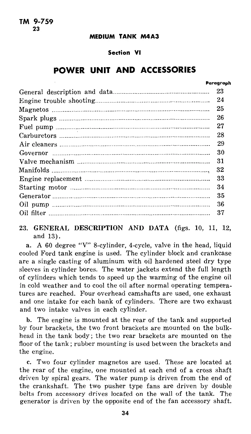
23. GENERAL DESCRIPTION AND DATA (figs. 10, 11, 12,
and 13).
a. A 60 degree “V” 8-cylinder, 4-cycle, valve in the head, liquid
cooled Ford tank engine is used. The cylinder block and crankcase
are a single casting of aluminum with oil hardened steel dry type
sleeves in cylinder bores. The water jackets extend the full length
of cylinders which tends to speed up the warming of the engine oil
in cold weather and to cool the oil after normal operating tempera-
tures are reached. Four overhead camshafts are used, one exhaust
and one intake for each bank of cylinders. There are two exhaust
and two intake valves in each cylinder.
b. The engine is mounted at the rear of the tank and supported
by four brackets, the two front brackets are mounted on the bulk-
head in the tank body; the two rear brackets are mounted on the
floor of the tank ; rubber mounting is used between the brackets and
the engine.
c. Two four cylinder magnetos are used. These are located at
the rear of the engine, one mounted at each end of a cross shaft
driven by spiral gears. The water pump is driven from the end of
the crankshaft. The two pusher type fans are driven by double
belts from accessory drives located on the wall of the tank. The
generator is driven by the opposite end of the fan accessory shaft.
34
<л
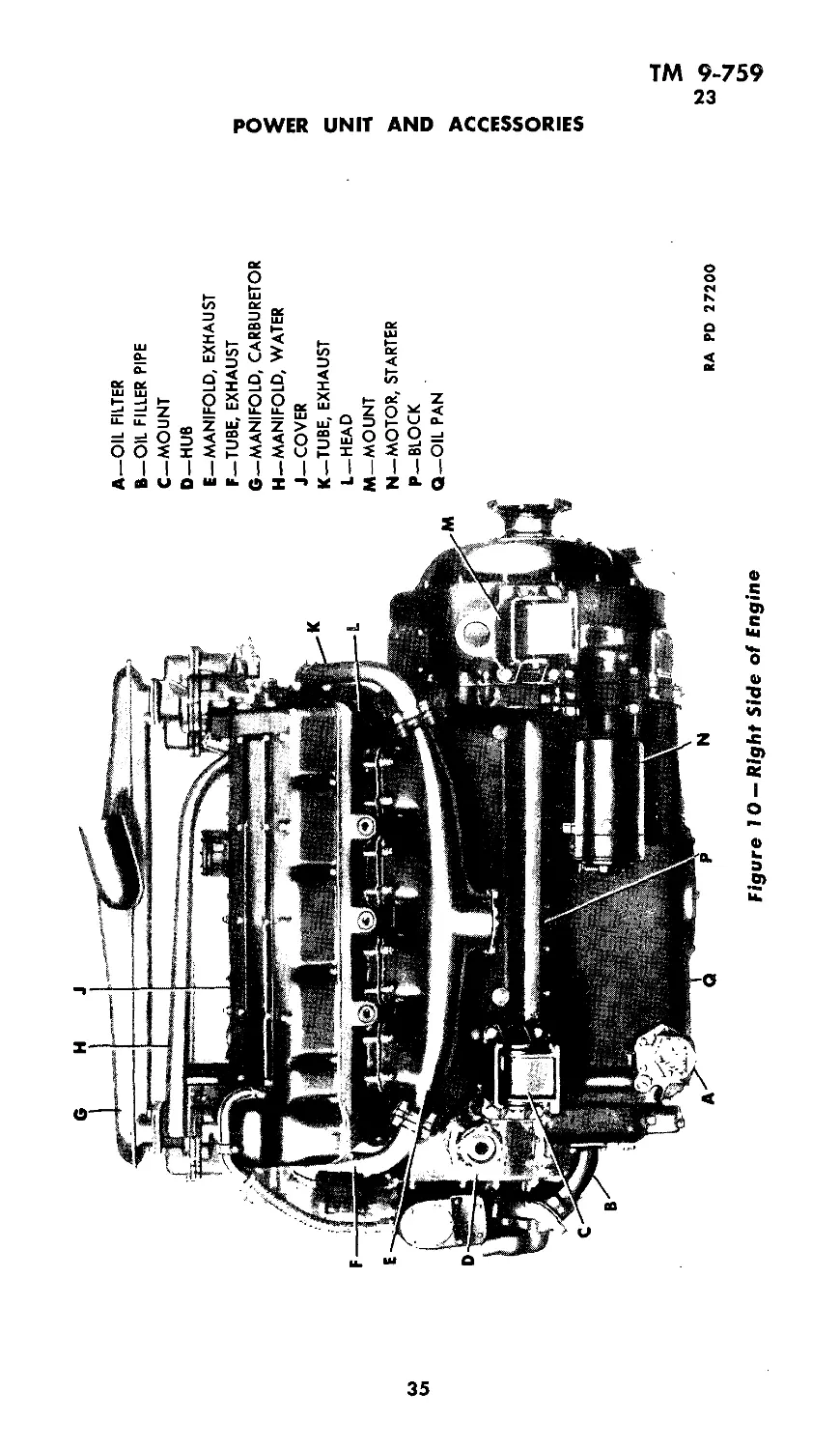
Figure 10 — Right Side of Engine
A—OIL FILTER
В—OIL FILLER PIPE
C—MOUNT
D—HUB
E—MANIFOLD, EXHAUST
F—TUBE, EXHAUST
G—MANIFOLD, CARBURETOR
H—MANIFOLD, WATER
J—COVER
K—TUBE, EXHAUST
L—HEAD
M—MOUNT
N—MOTOR, STARTER
P—BLOCK
Q—OIL PAN
POWER UNIT AND ACCESSORIES
RA PD 27200
(л
<O
A—MOUNT
В —TUBE,EXHAUST
C —COVER
D—MANIFOLD, CARBURETOR
E—MANIFOLD, WATER
F—HEAD
G-HUB
H—MOUNT
J —OIL PAN
K—GAUGE UNIT
L—MANIFOLD, EXHAUST
M—BLOCK
RA PD 27201
MEDIUM TANK M4A3
Figure J J — Left Side of Engine
ТМ 9-759
23
POWER UNIT AND ACCESSORIES
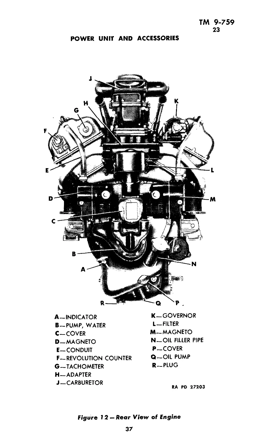
A—INDICATOR
B—PUMP, WATER
C-COVER
D—MAGNETO
E—CONDUIT
F—REVOLUTION COUNTER
G—TACHOMETER
H—ADAPTER
J—CARBURETOR
K—GOVERNOR
L-FILTER
M-MAGNETO
N—OIL FILLER PIPE
P-COVER
Q—OIL PUMP
R—PLUG
RA RD 27203
Figure 12 — Rear View of Engine
37
ТМ 9-759
23
MEDIUM TANK M4A3
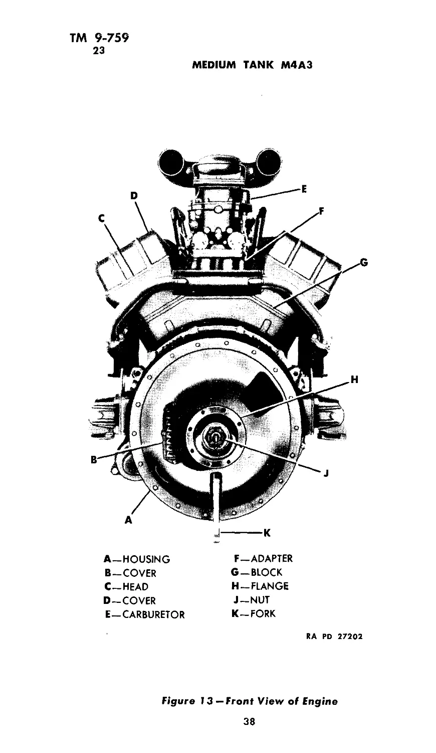
A—HOUSING
B—COVER
C—HEAD
D-COVER
E-CARBURETOR
F—ADAPTER
G —BLOCK
H-FLANGE
J—NUT
K—FORK
RA RD 27202
Figure 13 — Front View of Engine
38
TM 9-759
23
POWER UNIT AND ACCESSORIES
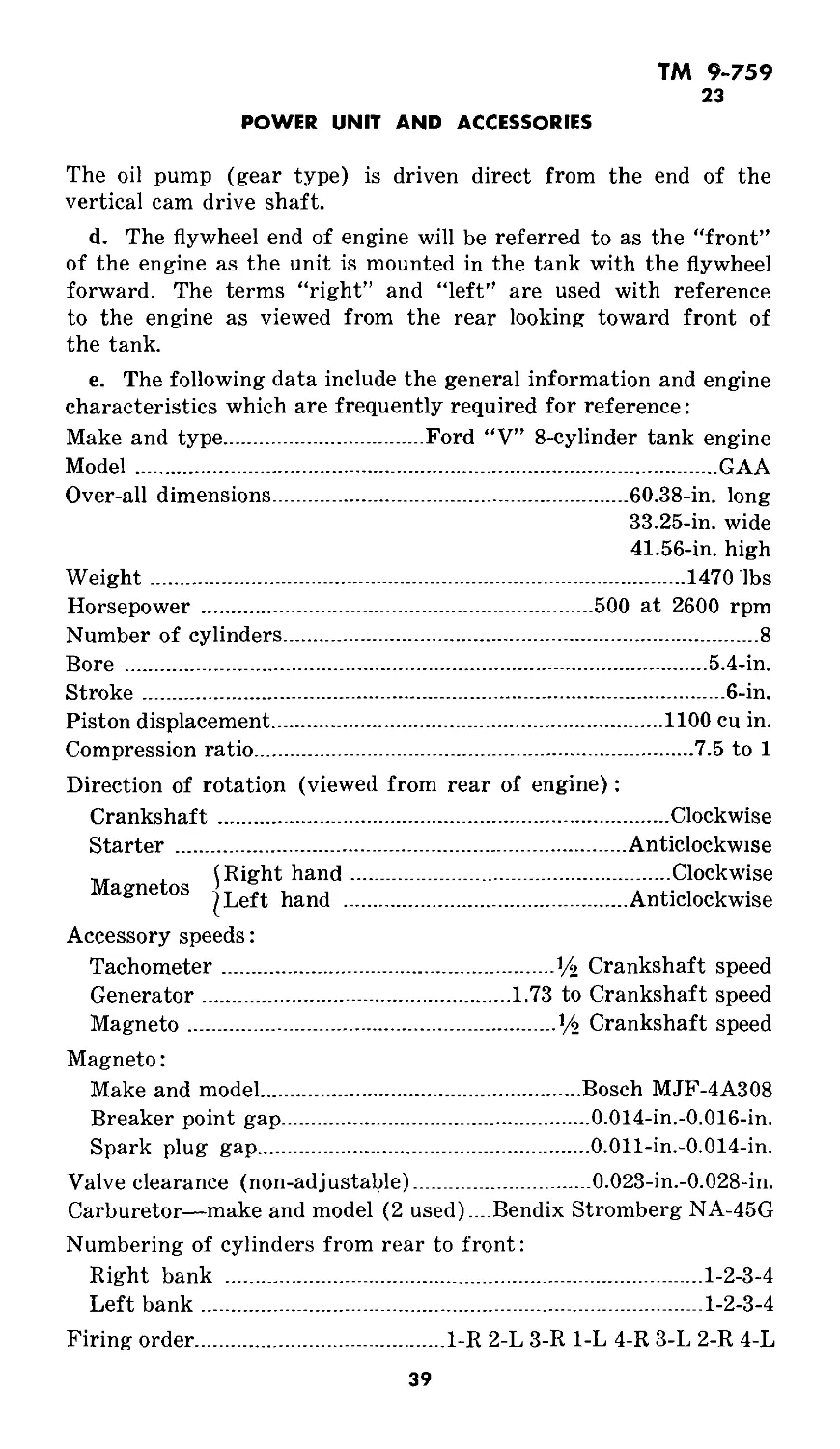
The oil pump (gear type) is driven direct from the end of the
vertical cam drive shaft.
d. The flywheel end of engine will be referred to as the “front”
of the engine as the unit is mounted in the tank with the flywheel
forward. The terms “right” and “left” are used with reference
to the engine as viewed from the rear looking toward front of
the tank.
e. The following data include the general information and engine
characteristics which are frequently required for reference:
Make and type.......................Ford “V” 8-cylinder tank engine
Model...........................................................GAA
Over-all dimensions...................................60.38-in. long
33.25-in. wide
41.56-in. high
.......1470 lbs
500 at 2600 rpm
.......8
.......5.4-in.
.......6-in.
.......1100 cu in.
.......7.5 to 1
....!/2 Crankshaft speed
1.73 to Crankshaft speed
....У2 Crankshaft speed
Weight..............
Horsepower .........
Number of cylinders.
Bore ...............
Stroke..............
Piston displacement-
compression ratio...
Direction of rotation (viewed from rear of engine):
Crankshaft...........................................Clockwise
Starter .........................................Anticlockwise
,, . (Right hand.................................Clockwise
agne os Anticlockwise
Accessory speeds:
Tachometer
Generator ...
Magneto.......
Magneto:
Make and model..................................Bosch MJF-4A308
Breaker point gap............................0.014-in.-0.016-in.
Spark plug gap........................... 0.011-in.-0.014-in.
Valve clearance (non-adjustable)..............._0.023-in.-0.028-in.
Carburetor—make and model (2 used)....Bendix Stromberg NA-45G
Numbering of cylinders from rear to front:
Right bank
Left bank ...
Firing order....
...................... .....1-2-3-4
......................... 1-2-3-4
1-R 2-L 3-R 1-L 4-R 3-L 2-R 4-L
39
ТМ 9-759
24
MEDIUM TANK M4A3
24. ENGINE TROUBLE SHOOTING.
a. If the engine fails to turn over when starter button is pressed:
(1) Check the specific gravity of the batteries. If reading is 1.225
or less, replace with a fully, charged battery and have the discharged
battery recharged. If reading is approximately 1.280 the battery is
fully charged.
(2) Examine battery terminals for corrosion, battery cable for
a short circuit or broken sections. If such conditions exist, clean the
terminals and replace the broken cables.
(3) Examine for loose connection at starter motor.
(4) Press the starter button to determine if the starter solenoid
is working. Disconnect the battery-starter motor cable at the starter
motor, and while another person operates the starter button, hold
the cable against the housing and observe whether a spark occurs.
If no spark is seen, replace the solenoid. If the starter does not
operate after replacing solenoid, replace the starter.
b. If the engine turns over but does not start.
(1) See that ignition switch is turned “on.”
(2) Check the amount of fuel in fuel tanks, and be sure the fuel
valves are open.
(3) Under priming or over priming. For under prime reprime
engine with two or three additional strokes. For over prime place
throttle in full open position and turn engine over with starter five
or six revolutions with magneto switch in “off” position.
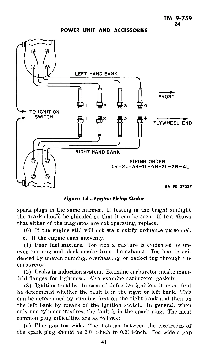
(4) Check fuel level in carburetors by removing float chamber
level plugs (see fig. 14). If fuel is not apparent at the carburetor
levels, disconnect the inlet lines to carburetors and > crank engine
with starting motor. If no fuel flows, remove fuel pump outlet lines
and blow out with air hose.
(5) After it has been determined that fuel is being supplied to
carburetors the ignition system should be checked as follows: Re-
move circular distributor plate from right hand magneto and hold
neon spark plug tester against each of the four high tension ter-
minals in turn while engine is being cranked with the starter. A
bright flash will show that the magneto, spark plugs and wire from
that terminal is operating satisfactorily. If dim light shows, check
wire and spark plug. Follow same procedure with left hand magneto.
If the neon tester is not available the test may be made as follows:
Remove the spark plug lead from the spark plug to be tested and
hold it approximately % inch away from a suitable ground con-
nection. Turn the engine over with the starting motor and if a
good spark is noticed the circuit is in good condition. Test the other
40
TM 9-759
24
POWER UNIT AND ACCESSORIES
Figure 14—Engine Firing Order
spark plugs in the same manner. If testing in the bright sunlight
the spark should be shielded so that it can be seen. If test shows
that either of the magnetos are not operating, replace.
(6) If the engine still will not start notify ordnance personnel.
c. If the engine runs unevenly.
(1) Poor fuel mixture. Too rich a mixture is evidenced by un-
even running and black smoke from the exhaust. Too lean is evi-
denced by uneven running, overheating, or back-firing through the
carburetor.
(2) Leaks in induction system. Examine carburetor intake mani-
fold flanges for tightness. Also examine carburetor gaskets.
(3) Ignition trouble. In case of defective ignition, it must first
be determined whether the fault is in the right or left bank. This
can be determined by running first on the right bank and then on
the left bank by means of the ignition switch. In general, when
only one cylinder misfires, the fault is in the spark plug. The most
common plug difficulties are as follows:
(a) Plug gap too wide. The distance between the electrodes of
the spark plug should be 0.Oil-inch to 0.014-inch. Too wide a gap
41
ТМ 9-759
24-25
MEDIUM TANK M4A3
increases the electrical resistance and interferes with the operation
of the engine.
(b) Plug short-circuited. This is usually caused by a cracked or
porous insulator, or by fouling of the electrodes or insulator. Any
of these conditions will cause misfiring by permitting the current to
stray from its intended path.
(c) Ignition wires. Misfiring of one cylinder, either continuous
or intermittent, may be due also to a chafed or broken wire. The
metal terminals of the cables must not come into contact with any
metal parts of the engine or the magneto, except those designated
as being correct according to the instructions given. If the wires
and plugs are in good condition and yet the ignition is irregular, the
trouble is probably with the magneto. This can be checked as out-
lined in paragraph 25, b.
(d) Damaged insulating parts. It sometimes happens that dis-
tributor plate and control arm cap parts of the magneto are damaged
through accident or carelessness. These parts should also be carefully
examined for possible disarrangement or damage which might per-
mit leakage of current.
(4) Valve and valve gear trouble. Check the valve clearances,
and the springs. Make sure the valves are not sticking.
(5) Poor fuel. Use only the recommended grade of gasoline and
see that it flows freely to the carburetor.
(6) Engine overheating. Excessive engine temperature may be
due to any of the following causes:
(a) Air flow restricted through radiator.
(b) Engine operating on too lean a fuel mixture.
(c) Engine operating on a retarded spark.
(d) Engine oil of improper grade, of insufficient quantity.
25. MAGNETOS.
a. Description. Two magnetos are used, one firing the cylinders
in the right block and the other firing the cylinders in the left block.
The right or left block is determined by looking at the engine
from the rear of the tank, looking toward the front. The number-
ing of the cylinders and the firing order is shown in figure 14. The
wires leading from the magneto distributor to the spark plugs may
be identified for both right and left hand magneto by colors marked
on the wires as follows: No. 1 red, No. 2 blue, No. 3 green, and No. 4
yellow.
b. Check ignition timing.
(1) Open top engine compartment doors.
(2) Remove plate over spark plugs in each block and remove
spark plug caps, wires and spark plugs.
42
TM 9-759
25
POWER UNIT AND ACCESSORIES
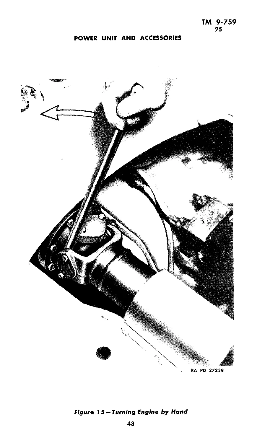
RA RD 27238
Figure 15 — Turning Engine by Hand
43
ТМ 9-759
25
MEDIUM TANK M4A3
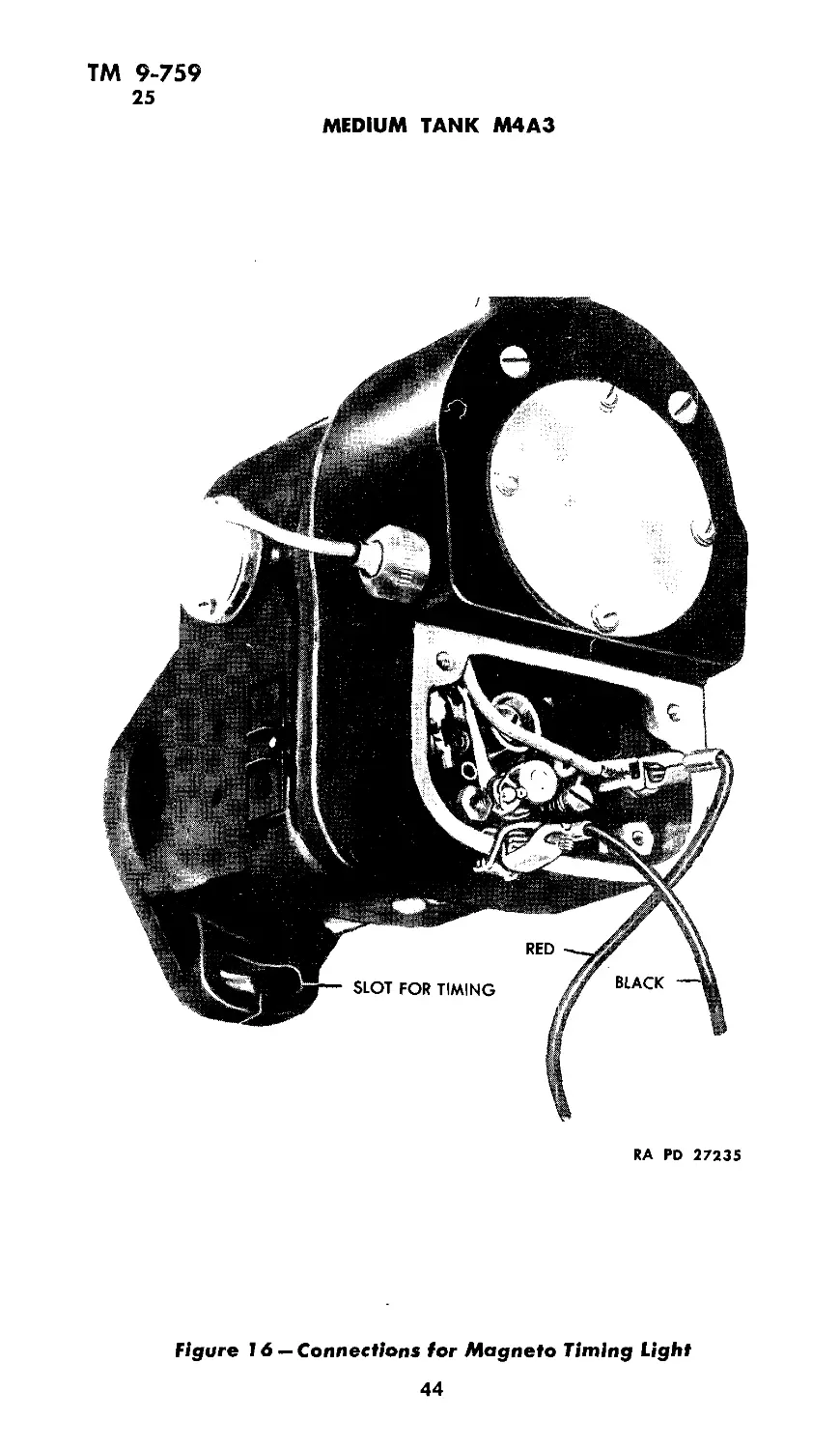
RA PD 27235
figure 16 — Connections for Magneto Timing Light
44
TM 9-759
25
POWER UNIT AND ACCESSORIES
Figure 17 — Magneto Rotor Arrow
RA RD 27234
(3) Remove timing plate on flywheel housing in front of left
block. To do this it is necessary to remove fire extinguisher nozzle
between side of left block and wall of tank; also remove small “Home-
lite” muffler mounted on bulkhead.
(4) Remove cover over rear universal joint and use bar for
turning engine as shown in figure 15. Use compression gage in
No. 1 spark plug hole and turn engine counterclockwise or from right
to left until compression gage shows No. 1 piston is coming up on
compression stroke. Then turn until No. 1 cylinder right hand mark
is approaching pointer in opening in flywheel housing.
(5) Remove magneto breaker point cover plates and connect one
of the red wires of the timing light to the primary connection of
the right hand magneto, and the other red wire to the primary con-
nection of the left hand magneto. Then ground the black wire to
either magneto frame as shown in figure 16.
(6) One man should be in position to observe flywheel timing
marks, and another to turn engine a small amount at a time. Place
the ignition switch on instrument board on “R”; turn engine only
a very small amount at a time until right indicator light goes “on”
showing the breaker points have just opened.
(7) The flywheel mark “Spark Retarded” should be under the
pointer (fig. 17).
45
ТМ 9-759
25-26
MEDIUM TANK M4A3
c. Ignition timing.
(1) Should the flywheel mark be past the pointer when the timing
light goes on, the timing is late, in which case it will be necessary
to advance the magneto in the housing slots (fig. 17).
(2) Loosen the upper and lower holding nuts and move the mag-
neto counterclockwise, slightly back up the flywheel to remove back-
lash and check again. (Clockwise or counterclockwise is looking at
magnetos from coupling ends.)
(3) Tighten holding nuts after correct timing is obtained. NOTE:
To time the left magneto, turn the engine approximately two revo-
lutions before using the compression gage on No. 1 cylinder in the
left cylinder block. Turn ignition switch to “L” and proceed the
same as for right block.
d. Magneto replacement.
(1) Removal
(a) Remove the four screws securing the breaker point inspection
plate and remove the plate.
(b) Remove the four screws securing the magneto distributor
circular inspection plate; and remove the plate.
(c) Remove the screw holding the ground wire.
(d) Unscrew the knurled nut securing the ground wire conduit
to the magneto housing, and remove the ground wire and conduit.
(e) Remove the four screws securing the four ignition (high
tension) cables to the distributor plate and lift the ignition cables
out of the recesses.
(f) Unscrew the knurled nut securing the ignition cable conduit
to the magneto and remove the conduit and cables.
(g) Remove one upper and one lower nut securing the magneto
to the timing gear case and remove the magneto.
(h) CAUTION: Note the position of the arrow in the center of
the distributor plate before removing the magneto. The magneto
must be replaced with the arrow pointing to the same terminal as
when removed.
(2) Installation. Reverse the sequence of removal operations to
install, and time the magneto in accordance with the procedure in
paragraph 25 c.
26. SPARK PLUGS.
a. Description. The spark plugs used are the Aircraft type,
Champion C88-S, and are radio shielded. The spark gap is 0.011-
inch to 0.014-inch.
46
TM 9-759
26-28
POWER UNIT AND ACCESSORIES
b. Removal.
(1) Remove plates over spark plug compartment, shield caps
from spark plugs and spark plug wires.
(2) Remove spark plugs.
c. Installation. When installing spark plugs do not use a wrench
with handle more than 10 inches long. It is possible to distort cer-
tain sections of the plug if too much force is used in tightening.
27. FUEL PUMP.
a. Description. The fuel pump is of the automotive diaphragm
type (AC) and is mounted on left cylinder bank and is driven by
left intake camshaft. The pump maintains a pressure of five pounds
to the carburetor.
b. Maintenance. At the 250 mile inspection check for leakage at
connections and fittings.
c. Removal. In the event the fuel pump fails to supply a suffi-
cient quantity of fuel, the pump should be replaced with a service-
able unit. The following procedure should be followed:
(1) Close fuel shut-off valves.
(2) Disconnect fuel lines attached to pump. (Disconnect the
pump to carburetor fuel lines at carburetor before attempting to
remove from pump.)
(3) Remove the two nuts which hold the pump to cylinder head
and remove the pump.
d. Installation. Proceed in reverse order given in paragraph 27 c.
28. CARBURETORS.
a. Description. Two Stromberg model NA-Y5G Carburetors are
used, one mounted at each end of the intake manifold. The car-
buretor is a double barreled down-draft unit. It has two floats con-
nected by one lever and operating one needle valve. A separate main
metering and idling system is provided for each barrel. Each
barrel is equipped with a vacuum operated degasser and an elec-
trical control for positive shut-off of the fuel when stopping the
engine. This is controlled by a toggle switch on the instrument
panel, and is used in case the engine continues to turn over after the
ignition switch is cut off due to preignition or faulty wiring.
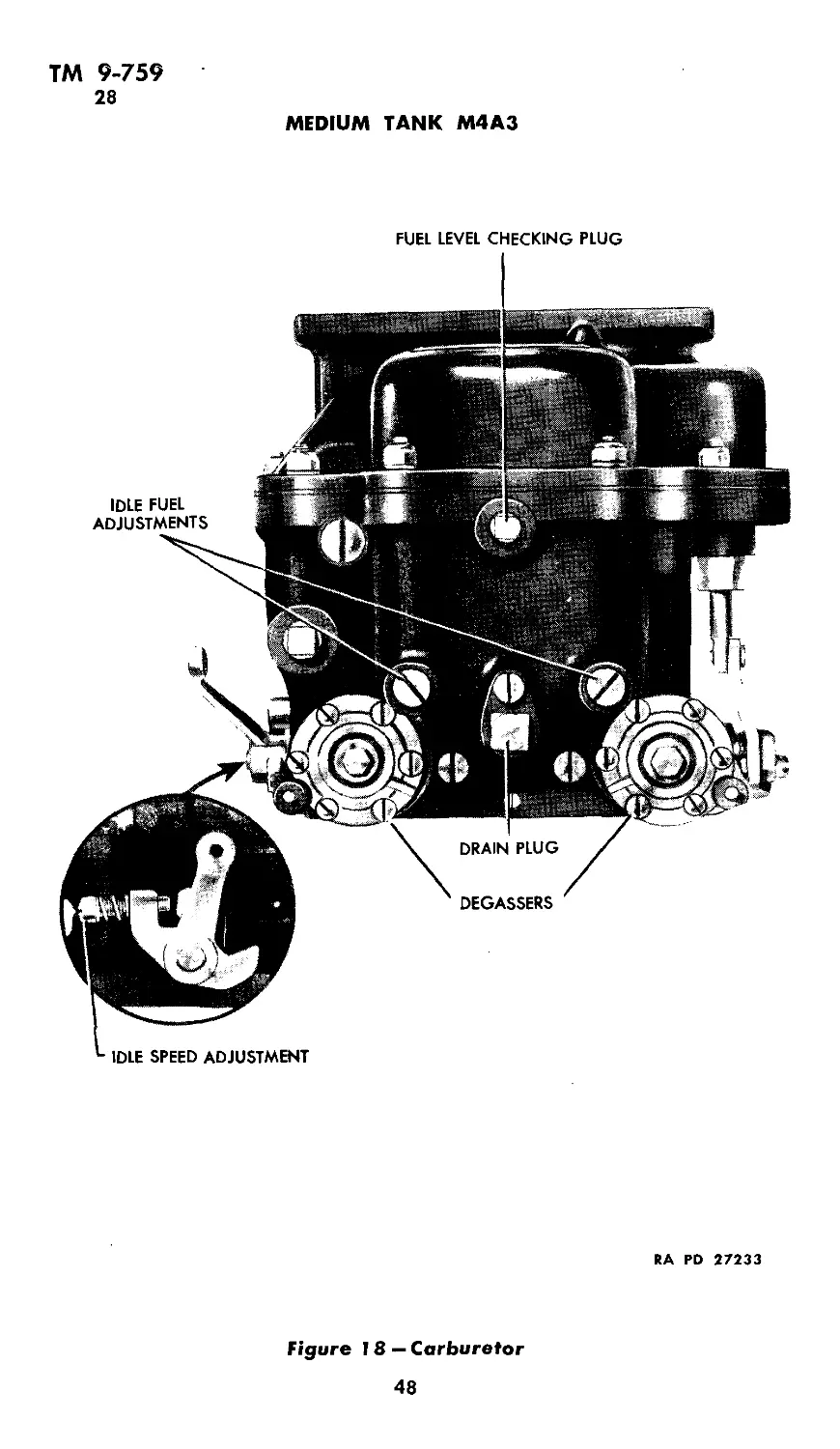
b. Idle adjustment. The idle fuel adjusting screws are shown in
figure 18. There is one for each carburetor barrel.
(1) Make idle fuel adjustments with engine stopped.
(2) Seat each idle fuel adjusting screw lightly, and then turn
out each screw % turn. There are two adjusting screws on each
carburetor, one for each throttle barrel.
47
ТМ 9-759
28
MEDIUM TANK M4A3
FUEL LEVEL CHECKING PLUG
RA RD 27233
Figure 18 — Carburetor
48
ТМ 9-759
28-29
POWER UNIT AND ACCESSORIES
(3) Adjust idle speed adjusting screw so that it is turn open
from closed position.
(4) Start the engine and run until it reaches normal operating
temperature. After engine is warmed up set idle speed adjusting
screw so that the engine idles at 500 rpm.
c. Removal. To remove carburetors proceed as follows:
(1) Remove the six nuts at the top of each carburetor which
hold the air cleaner manifold.
(2) Disconnect the two air cleaner manifold hose pipes, by loosen-
ing the clamps and remove air cleaner manifold.
(3) Disconnect gas feed line at each carburetor. NOTE: A small
cork should be available to cork the intake to prevent gasoline from
running out when feed line is disconnected.
(4) Disconnect degasser electrical connections at each side of
carburetor.
(5) Remove the four carburetor base nuts which hold the car-
buretor to the manifold.
(6) Disconnect throttle rod at each carburetor and remove the
carburetors.
d. Installation. The carburetors may be replaced by reversing
the procedure outlined above.
29. AIR CLEANERS.
a. Description. Two air cleaners of the oil bath type are located
one at the right and one at the left of the fighting compartment
mounted on the forward side of the bulkhead.
b. Maintenance. Daily or after every eight hours of operation in
mild dust conditions, service the air cleaners as follows:
(1) Daily servicing. Turn turret until the door in the turret
exposes the air cleaner. Remove the three wing nuts from the bot-
tom plate of the cleaner, and remove the baffle and cup assembly.
Remove the baffle from the cup and clean both baffle and cup thor-
oughly. Refill the cup to proper level with oil specified (see lubrica-
tion chart, Section IV). Care should be taken not to fill the cup over
the oil level mark. Place the bottom plate on cleaner and fasten with
the three wing nuts.
(2) Cleaning filter element. After 25 hours of normal engine
operation, clean the filter element by first removing the baffle and
cup assembly, and then removing the filter element by pulling the
clip down. Wash filter elements with cleaning fluid or gasoline. Dry
and blow out with compressed air in reverse direction to normal
air travel.
49
ТМ 9-759
29-33
MEDIUM TANK M4A3
c. Removal.
(1) Turn turret until door in turret exposes air cleaner.
(2) Disconnect rubber outlet connection to carburetor air intake
manifold.
(3) Remove the cup from the cleaner.
(4) Remove four cap screws connecting cleaner to bulkhead.
(5) Lift out cleaner.
d. Installation. Reverse the sequence of removal operation.
30. GOVERNOR.
The governor is used to regulate and limit the speed of the engine,
thus preventing dangerous over-speeding. The unit is located at the
rear of right hand cylinder head. The governor is set to limit the
engine speed to 2650 rpm under full load and should not be tampered
with except by ordnance maintenance personnel.
31. VALVE MECHANISM.
Two inlet and two exhaust valves are provided for each cylinder
and are operated by overhead camshafts, two in each cylinder head,
one shaft operating the intake valves and the other operating the
exhaust valves. Special non-adjustable tappets are used. The
clearance of 0.023-inch to 0.028-inch is determined during manu-
facture, and should require no attention other than checking as both
intake and exhaust valve ports are provided with steel inserts. The
tappet clearance should remain constant over a long period of opera-
tion. In the event the clearance becomes too small, it will be neces-
sary to grind off valve stem to obtain correct clearance.
32. MANIFOLDS.
a. Description. The intake manifold is cast in the cylinder head,
and is open at each end where the front and rear carburetors are
attached. Two exhaust manifolds are used and are bolted directly
to right and left side of the block and connected to each other at
the rear. Each exhaust manifold is connected to a separate ex-
haust pipe.
33. ENGINE REPLACEMENT.
a. Removal.
(1) Open the door at the rear of the engine compartment. To
open this door all the way raise the radiator air baffle and allow it
to rest on top of the door after the door is open.
(2) Remove plug in engine compartment floor plate.
(3) Open drain valve at bottom of water pump and drain through
the hole in floor plate.
50
ТМ 9-759
33-34
POWER UNIT AND ACCESSORIES
(4) Remove engine compartment floor plate.
(5) Drain engine oil pan.
(6) Remove the nuts securing water pump, disconnect the water
pump hose and remove the water pump.
(7) Remove radiator top hose and two condenser tank hoses.
(8) Open the grilled engine compartment doors and remove the
front and rear hatch plates.
(9) Disconnect fan belts on each side of engine by loosening ac-
cessory drive adjustments.
(10) Remove four bolts in each fan shroud.
(11) Remove fan assemblies from engine compartment.
(12) Turn off battery master switch.
(13) Disconnect starter lead at starter.
(14) Disconnect generator armature and generator field lead
at generator.
(15) Disconnect oil level indicator on left side of the oil pan.
(16) Disconnect oil pressure lead at right rear of the crankcase.
(17) Disconnect two magneto ground wires at the magnetos.
(18) Disconnect degasser wires from carburetors and degasser
conduit from engine.
(19) Disconnect the right and left accessory drive shafts from
the respective accessory drive housings.
(20) Remove the accessory drive housings.
(21) Disconnect the tachometer from left cylinder head.
(22) Disconnect the clutch release rod at the clutch housing.
(23) Remove the circular spacer plate around the clutch housing.
(24) Shut off the fuel valves and disconnect the fuel line from
the fuel pump.
(25) Disconnect throttle control rod.
(26) Disconnect air cleaner outlet pipes at the air cleaners.
(27) Disconnect driveshaft bolts at clutch shaft flange.
(28) Remove bolts securing the engine to the four support
brackets.
(29) Disconnect exhaust pipe from exhaust manifold.
(30) Secure lifting sling to four engine lifting eyes.
(31) Remove engine from hull.
b. Installation. Reverse the sequence of removal operations.
34. STARTING MOTOR.
a. Description. The starting motor is a 24 volt type mounted on
the right side of flywheel housing and its power is transmitted to
the engine through an automatic drive. A solenoid switch located
on right forward side of bulkhead closes the electrical circuit of the
starting motor when the starter button on the instrument board is
51
ТМ 9-759
34-37
MEDIUM TANK M4A3
pressed. Rotation of the starter motor shaft causes the pinion of
the automatic drive to advance and mesh with the flywheel. After
the engine starts and the flywheel speed exceeds that of the starting
motor, the pinion releases from the flywheel automatically. The
starting motor bearings do not require lubricating.
b. Removal. Disconnect the two starter wires and remove three
nuts which hold the starter motor to the crankcase flange and remove
the starter.
c. Installation. Reverse above procedure. Refer to the wiring
diagram, figure 19.
35. GENERATOR.
a. Description. A special Ford tank generator model GAA is
used. The generator is 30 volt, 50 ampere capacity and current
control is obtained by a generator regulator mounted underneath
floor of turret. The generator is mounted on the accessory drive
housing and driven by the accessory shaft.
b. Lubrication. Generators are properly lubricated at engine
overhaul periods and should not require additional lubrication be-
tween overhaul periods.
c. Removal. A faulty generator should be replaced as follows:
(1) Turn off battery master switch.
(2) Disconnect wires from armature and field terminals.
(3) Disconnect flexible conduit.
(4) Remove the four nuts which hold the generator to accessory
case and remove the generator.
d. Installation. Reverse procedure as outlined above. Refer to
the wiring diagram, figure 19.
36. OIL PUMP.
a. Description. The oil pump is a gear type driven from the cam-
shaft driveshaft. The oil pump should require no periodical check.
b. Removal. Remove engine compartment floor plate. Remove
the four nuts holding the oil pump to the crankcase and remove
the pump.
c. Installation. Secure the pump to the crankcase with the four
nuts. Replace the engine compartment floor plate.
37. OIL FILTER.
a. Description. The oil filter is the motorized “Cuno” type located
on the right side of the oil pan at the rear, accessible through the
rear door.
52
HEAD LAMP-
MARKER
BLACK
GREEN
YELLOW
CD* DISENGAGING SWITCH I
RED ALL STABILIZER
DOME LAMPS
Ln
GJ
HEAD LAMP 5
MARKER LAMP
HULL
LAMPS
A
CONTROL BOX
BLACKOUT
DRIVE
HEAD LAMP
CONNECTOR
SOL.
CHROME I
SWITCH
TURRET i
MOTOR i
^STARTER
I RELAY
(n.
FUEL TANK UNIT
WHITE
RECOIL SW
FUEL CUT-OFF
RADIO
TERMINAL
CONTROL BOX
GREEN
WATER TEMP.-^^O-j-
WATER TEMP. SIGNAL ______________J
B-O DRIVE
SIREN
3-48
2-48
I -"18
4-48
5-42
+ -•6
SHIELDED BLACK
YELLOW-------
RED---------
SHIELDED RED
BLACK--------
BLACK-------
--------1 TURRET
I WIRING
[ SLIP RING-*
18 SHIELDED (BLACK)
YELLOW
18 RED
18 SHIELDED
(RED)
5*12 BLACK
3
REG
*6 BLACK
TO PANEL
TO PANEL
HEAD LAMP ft
MARKER LAMP
SIREN
SW.
STOP
LIGHT
SW.
FRONT
TERMINAL
RADIO
TERMINAL BOX
TRANSMISSION
TEMP
«2
BLACK
REG
AUX.
GEN.
TO PANEL
111 0
ЦI
LOW OIL PRESSURE
OIL PRESSURE
*2 BLACK-}
еГуН 0|L level^
STARTER ,
•в BLACK (ARMATURE)
*14 YELLOW (FIELD)
SOCKET
*15
TROUBLE
TERMINAL
BOX
14 RED
BLACKOUT
TAIL
BLACKOUT
STOP
TACHOMETER
FUEL TANK UNIT
CENTER
TERMINAL
/ BOX
I BLACK-WHITE TR
2 GREEN
3 RED-WHITE TR
4 BLUE
5 TAN'
6 BLUE-BLACK TR
7 YELLOW-RED TR
8 WHITE-RED TR
9 WHITE-GREEN TR
IO RED-GREEN TR
II ORANGE-BLACK TR 14
12 ORANGE 14
13 RED 14
14
14
14
14
14
14
14
14
14
14
BLACK
WHITE
TAN-BLACK TR
CHROME
YELLOW
— KEY —
15
16
17
18
19
20 WHITE-BLACK TR
21 BLACK-RED TR
22 YELLOW-BLACK TR
23 BLUE-RED TR
24 GREEN-BLACK TR
25 YELLOW-BLUE TR
26 BLACK
27 BLACK
14
14
14
14
14
14
14
14
14
14
14
14
14 RED-BLACK TR 14 28 CHROME-BLACK TR 14
Figure 19 — Wiring Diagram
BLACKOUT
TAIL
-SERVICE
TAIL
-SERVICE
STOP
RA PD 27199
N
*o
I
Ui
>0
ТМ 9-759
37
MEDIUM TANK M4A3
b. Operation check. To check the operation of the filter, reverse
the manual turning nut, and turn the engine over with the starter.
The manual turning nut will rotate if the filter is operating. After
the check is made, replace the manual turning nut in original posi-
tion and secure with lock wire.
c. Removal. Unscrew the six cap screws securing the motor and
filter element to the crankcase, and remove motor and filter element.
d. Installation
(1) Clean the filter body before installing the motor and filtering
element.
(2) Replace the motor and filter element and secure with the six
cap screws.
54
ТМ 9-759
38-40
Section VII
REFERENCES
Paragraph
Standard nomenclature lists............................... 38
Technical and field manuals...................,.................... 39
Miscellaneous publications ............................... 40
38. STANDARD NOMENCLATURE LISTS.
Gun, cal. .30, Browning, M1919A4, fixed and flexible bow
mounts ........................................ SNL A-6
Gun, sub-machine, cal. .45, Thompson, M1928A1........ SNL A-32
Gun, machine, cal. .50, Browning, М2, heavy barrel, fixed
and flexible and ground mounts........ ......... SNL A-39
Materiel, 75-mm, tank gun, М2, М3................... SNL C-34
Tank, medium, M4A2 (in preparation).................. SNL G-104
Vol. VIII
39. TECHNICAL AND FIELD MANUALS.
75-mm tank gun materiel............................. TM 9-307
Cleaning, preserving, and lubricating materials_____ TM 9-850
Browning machine gun, cal. .50, all types............. TM 9-1225
Stabilizers, all types______________________________ TM 9-1799
Fire prevention, safety precautions, accidents______ TM 10-360
Sheet metal work, body, fender and radiator repairs. TM 10-450
Echelon system of maintenance..................... TM 10-525
Automotive lubrication ........................ TM 10-540
Motor transport inspection.......................... TM 10-545
Automotive electricity ........................... TM 10-580
Defense against chemical attack...................... FM 21-40
Gun, sub-machine, cal. .45, Thompson, M1928A1......... FM 23-40
Gun, cal. .30, Browning, M1919A4...................... FM 23-50
40. MISCELLANEOUS PUBLICATIONS.
Military motor vehicles............................. AR 850-15
Storage of motor vehicle equipment.................... AR 850-18
Detailed lubrication instructions for ordnance
materiel......................................... OFSB 6 Series
55
ТМ 9-759
MEDIUM TANK M4A3
INDEX
A Page No.
Accessories (See Power unit and
accessories)
Accessory speeds, data on...... 39
Adjustments, idle fuel......47-49
Air cleaners
Description of............. 49
Lubrication of............. 26
Maintenance
Cleaning filter element.... 49
Daily servicing.......... 49
Removal and installation of.... 50
Air outlet rubber hose connec-
tions, inspection of............ 26
Air space in tank............ 31
Ammeter, location and function
of ............................. 14
Armament ....................... 3-6
Armor thickness, data on....... 6
Auxiliary generator, lubrication
of ...........................26-27
Battery
Charging ....................... 3
Checking and cleaning........... 31
Electrical power shut off at....15-17
Faults, indication of by...am-
meter and voltmeter 14
Gravity of, checking.......... 40
Battery master switch
Location and operation of....15-17
Battery water, replenishing.... 31
Blackout driving light switch,
function of and caution for.... 12
Bosch magnetos, operation of... 13
Brackets, location of............. 34
Brakes, location and description
of
Parking brake.................... 8
Service brakes.................. 8
Cable C
Arrangement of for “short
hitch” ....................... 22
Care of while tracking....... 22
Precaution while towing...... 21
Capacity of hydraulic oil tank. .. 27
C^—Cont’d Page No.
Carburetor
Data on........................ 39
Description of ............... 47
Idle adjustment of..........47-49
Removal and installation of.. 49
Castings, detecting cracks in.. 28
Characteristics of engine (See
Data, tabulated)
Charts, lubrication
Power drive units.............. 24
. Suspension ................... 25
Checks (See Inspection)
Circuit breakers, location and
function of.................... 13
Cleaning
Battery and compartment....... 31
Filter element ............... 49
Floors ..................... 31
Transmission filler........... 26
Clearance
Cable and tracks............... 22
Clutch pedal, inspection of.. 29
Steering mechanism............ 29
Tappet ....................... 50
Valve ........................ 39
Clock, location of.............. 13
Clutch
Location and operation of.... 8
Precautions in operating..... 20
Cold weather starting........... 12
Communication, data on........... 6
Compartment light rheostat..... 13
Compression ratio .............. 39
Controls, general information on 8-18
Ammeter ...................... 14
Battery master switch........15-17
Blackout driving light switch.. 12
Brakes ........................ 8
Circuit breakers.............. 13
Clock ........................ 13
Clutch ........................ 8
Engine temperature gage...... 15
Fuel cut-out.................. 13
Gages
Engine temperature ......... 15
Fuel level ................ 15
Oil level .................. 15
56
TM 9-759
INDEX
C^—Cont’d Page No.
Controls—Cont’d
Oil pressure................. 14
Oil temperature ............. 15
Gear shifting.............17-18
Ignition switch ............... 13
Light switches .............. 8-12
Primer ......................12-13
Rheostat, compartment light.... 13
Selector switch ............... 15
Signals, low oil pressure.... 15
Spark control................... 8
Speedometer ................... 15
Starter switch ................ 12
Steering levers ............... 8
Tachometer .................... 14
Throttle controls........... 8
Utility outlet ................ 8
Voltmeter...................... 14
Coolant in engine, temperature
of ............................. 17
Cooling
System, description of.............. 15
Valves and engine.............. 22
Cracks, detection of............. 28
Crankcase
Description of................. 34
Lubrication of................. 26
Crankshafts, overhead............ 34
Crew, number of................... 7
Cylinder block, description of. 34
Cylinder (s)
Numbering of.................... 39
Trouble from excessive priming 13
D
Data, tabulated
Armament ..................... 3-6
Armor thickness............... 6
Communication ................ 6
Crew ........................ 7
Dimensions ................... 3
Engine ................... 3, 39
Fuel and oil.................. 6
Performance of engine....... 6-7
Periscopes .................. 6
Tracks ...................... 7
Turret...................... 6
Weight ....................... 3
Degasser, use of.............. 47
D---Cont’d Page No.
Description
Air cleaners................. 49
Carburetors .................. 47
Fuel pump................... 47
Generator..................... 52
Magnetos ..................... 42
Manifolds..................... 50
Oil filter.................... 52
Oil pump...................... 52
Power unit..................34-39
Spark plugs................... 46
Starting motor..............51-52
Turret........................ 3
Vehicle ....................... 3
Dimensions
Engine ...................... 39
Vehicle .................... 3
Draining
Air cleaners................. 26
Crankcase ........ ... 26
Floors ....................... 31
Gear cases. .. 26
Hydraulic oil tank........... 27
E
Electrical generating system,
auxiliary ..................... 3
Electrical power, shut off.....15-17
Engine
Data, tabulated ................ 3, 39
Description of ... ...34-39
Inspection
During operation............. 29
Prestarting ...............28-29
Lubrication
Additional instructions on
individual units and parts..23-27
General instructions for..... 23
Generators .................. 23
Guide ....................... 23
Reports and records........ 23
Mounting of on vehicle....... 34
Overheating, causes of....... 42
Performance ................ 6-7
Indications of .............. 21
Priming, excessive............ 13
Replacement .................50-51
Speed, regulation of by gov-
ernor ....................... 14, 50
Starting instructions.......... 18
57
ТМ 9-759
MEDIUM TANK M4A3
E—Cont'd Page No.
Engine—Cont’d
Stopping... 22
Toggle switch, use of......... 13
Temperature of.............. 15
Test......................18-20
Trouble shooting..........40-42
(See also Power unit and ac-
cessories)
Engine temperature gage, loca-
tion and use of....... 15
Engine trouble shooting
Failure to turn over.......... 40
Turning over and failure to
start ................. 40-41
Uneven running ...........41-42
Equipment for towing.......... 21
Exhaust manifolds............. 50
F
Failure of engine to turn and to
start ........................ 40-41
Fans .......................... .34
Filter element, cleaning......... 4!)
Filters (See Oil filter and Fuel
filter)
Fire hazard, caution in eliminat-
ing ......................... 31
Firing order .................. .3!)
Fittings, lubrication of......23-26
Flooding, cause of................ 13
Floors, draining and cleaning.... -31
“Front” side of engine
Definition of................. 3!)
Illustration of................ 38
Fuel
I lata on........................ 6
Use of recommended grade of.. 42
Fuel cut-out, location and opera-
tion of.......................... 13
Fuel filter, lubrication of....... 27
Fuel level gage, location and use
of ........................... 15
Fuel pump
Description of.................... 47
Maintenance of........... ...... 47
Removal and installation of.... 47
G Page No.
Gage(s)
Engine temperature............... 15
Fuel level..................... 15
Indication of engine perform-
ance by........................ 21
Inspection of during operation 29
Oil level ..................... 15
Oil pressure .................. 15
Oil temperature ............... 14
Gas tank cap, precaution before
removing ........................ 31
Gear cases, lubrication of........... 26
Gear shift lever
Location of and equipment for 17
Use of in shifting...........17-18
Gear shifting
Description ..................... 17
Operation .................. 17-18
Instructions for ..........20-21
Generator, auxiliary (See Aux-
iliary generator)
Generator regulator, use of..... 14
Generator(s)
Description of .................. 52
Lubrication of..................23, 52
Removal and installation of... 52
Governor, location and use of... 50
Ground clearance .............. .3
Grousers........................ 21
Guide, lubrication............... 23
Gun(s)
Armament for vehicle............ 3-6
Elevation of during prestart-
ing inspection .............. 28
H
Horsepower, engine .............. 39
Hot weather, operation in....... 31
Hydraulic oil tank, lubrication of 27
I
Idle fuel adjusting screws.....47-49
Idling the engine................ 20
Ignition
Timing .......................... 46
Checking ..................42-45
Trouble ................. 41
Wires, damaged................. 42
58
TM 9-759
INDEX
I—Cont’d Page No.
Ignition switch, location and op-
eration of...................... 13
Indirect vision devices........... 6
Induction system, leaks in.... 41
Inspection (s)
After operation..............30-31
Air outlet rubber hose connec-
tion .......................... 26
At the halt..................29-30
During operation............... 29
Periodic ....................31-33
After 250 miles of operation..31-32
After 1000 miles of operation..32-33
Prestarting .................28-29
Purpose of..................... 28
Instrument panel nomenclature.. 11
(See also Controls, general in-
formation )
Insulating parts, damaged....... 42
Intake manifold................. 50
Intervals of lubrication......... 26
L
Leakage, report of............. 26
Leaks in induction system....... 41
“Left” side of engine
Definition of.................. 13, 39
Illustration of.............. 36
Light switches, positions and lo-
cation of ..................... 8-12
Low oil pressure
Indication of during operation 29
Signals of.................. 15
Lubrication
Air cleaners................ 26
Auxiliary generator.........26-27
Chart
Power drive units............ 24
Suspension .................. 25
Crankcase ..................... 26
Fittings ....................23-26
Fuel filter.................... 27
Gear cases..................... 26
Generators ................... 23, 52
Hydraulic oil tank............ 27
Intervals of.. 26
Notes....................... 23-27
Oil can points................. 27
Oil filter..................... 27
Points not requiring........... 27
L—Cont’d Page No.
Lubrication—Cont’d
Reports and records........... 23
Slip joint....................... 27
Universal joints................ 27
M
Magneto (s)
Damaged parts of.............. 42
Data on.......................... 39
Description of................... 42
Ignition timing.................. 46
Checking ....................42-45
Location of...................... 34
Operation of..................... 13
Replacement of................... 46
Maintenance
Air cleaners...................26, 49
Fuel pump................... 47
(See also Lubrication)
Make and type of engine......... 39
Malfunction of units, report of ... 28
Manifolds, description of....... 50
Master switch, battery.......15-17
Metal parts, detecting cracks in.. 28
Misfiring, causes of.......... 42
Model of engine.................. 39
Motor (See Starting motor)
N
Nomenclature of instrument
panel ..................... 11
Notes on lubrication of parts.23-27
Numbering cylinders.......... 39
Oil °
Checking circulation of 26
Data on 6
Warming and cooling of 34
Oil can points, lubrication of 27
Oil filter
Description of 52
Lubrication of 27
Operation of 54
Checking ... 31
Removal and installation of. .. 54
Oil gage needle, unsteady 29
Oil level, checking 26
Oil level gage, location and func-
tion of 15
59
ТМ 9-759
MEDIUM TANK M4A3
O^—Cont’d Page No.
Oil pressure gage, location of. 15
Oil pressure (low)
Dropping of................... 15
Indication of during operation 29
Signals of .................. 15
Oil pump
Description .................... 52
Removal and installation..... 52
Oil temperature gage, location
and use of......... 14
Operating instructions and con-
trols
Controls ... ...... 8-18
(For specific names see Con-
trols, general information
on)
Engine test ................18-20
Prestarting inspection .....28-29
Starting instructions ........ 18
Stopping the engine............... 22
Vehicle ................... 20-22
Instructions .............20-21
Towing
Equipment for .... 21
Method of ............... 22
Precautions in ........21-22
Operation
Inspection after .............30-31
Inspection during ............ 29
Oil filter, checking.......... 54
Outlets, utility, location and use
of ............................ 8
Over priming the engine........ 13
Overheating the engine
Causes of .................... 42
Result of .................... 15
Overloading circuits ........... 13
P
Padding, protective ............. 6
Parking brake
Location and description of.. 8
Releasing .................... 20
Performance of engine
Data on ....................... 6-7
Indications of ............... 21
Periscopes, number and descrip-
tion of.......................... 6
P—Cont’d Page No.
Piston displacement ............. 39
Points requiring no lubrication.. 27
Power drive units, lubrication
chart on ....................... 24
Power unit and accessories
Air cleaners
Description of .............. 49
Maintenance of ............. 49
Removal and installation of.. 50
Carburetors
Description of................. 47
Idle adjustment ...........47-49
Removal and installation of 49
Data, tabulated ............... 39
Description of ..............34-39
Engine replacement
Installation .................. 51
Removal ...................50-51
Engine trouble shooting
Failure to turn over........... 40
Turning over but does not <
start .....................40-41
Uneven running ............41-42
Fuel pump ..................... 47
Generator...................... 52
Governor ...................... 50
Magnetos
Description of ................ 42
Ignition timing ............. 46
Checking ................42-45
Replacement of .............. 46
Manifolds 50
Oil filter
Description of .............. 52
Operation check of....... 54
Removal and installation of 54
Oil pump ...................... 52
Spark plugs
Description of ................ 46
Removal and installation of 47
Starting motor
Description of ............. 51-52
Removal and installation of 52
Valve mechanism ............... 50
Precautions in
Clutch, operating ............. 20
Fire hazard, eliminating........... 31
Gas tank, removal of........... 31
Towing ......................21-22
60
ТМ 9-759
INDEX
Р----Cont’d Page No.
Prestarting inspection ........28-29
Primer, location and operation
of ............................12-13
Protected vision ................. 6
Protective padding................ 6
Pump, priming .................12-13
R
Radio, data on.................... 6
Radio master switch.............. 17
Ratio, compression ............. 39
Reports and records of lubrica-
tion ........................... 23
Rheostat, compartment light..... 13
“Right” side of engine
Definition of ....................13, 39
Illustration of ............... 35
Rotation
Data on direction of............. 39
Turret ......................... 3
s
Safety button, operation of..... 12
Screws, idle fuel adjusting.....47-49
Seats, description of............ 6
Selector switch ................. 15
Service brakes, function of..... 8
Service lights ................ 8-12
Servicing, daily, of air cleaners.. 49
Shackles, towing, location and
use of ......................... 21
Shifting of gears (See Gear
shifting)
Short-circuited plug ............ 42
“Short hitch,” procedure for.... 22
Signals, low oil pressure....... 15
Slip joint, lubrication of...... 27
Spark control .................... 8
Description of ................ 46
Faults in
Ignition wires, damaged..... 42
Insulating parts, damaged.. 42
Plug gap too wide............41-42
Removal and installation of.... 47
Speedometer, location of and
equipment for ................... 15
S—Cont’d Page No.
Speed(s)
Accessory ..................... 39
Data on ....................... 6-7
Engine ......................... 14
Regulation of by governor... 50
Towing ......................... 21
Starter switch, function of..... 12
Starting instructions ........... 18
Starting motor
Description of...............51-52
Removal and installation of.... 52
Steering levers, location and use
of ............................. 8
Steering mechanism, checking of
during operation .............. 29
Steering the vehicle.............. 21
Stopping
Engine ........................ 22
Equipment .................... 47
Vehicle ........................ 21
Stroke ........................... 39
Suspension, lubrication chart on 25
Switches
Battery master ..............15-17
Blackout driving light...... 12
Ignition ....................... 13
Radio master ................... 17
Selector ....................... 15
Starter ........................ 12
Toggle ......................... 13
T
Tabulated data (See Data, tabu-
lated)
Tachometer, location and use of.. 14
Tappets .......................... 50
Temperature
Engine ........................ 15
Gages, use of for indicating ... 17
Test of engine...............18-20
Throttle controls, location of.. 8
Throttle stop screw, adjustment
of ...................'........ 14
Timing, ignition (See under Ig-
nition)
Toggle switch
Location and operation of...... 13
Use of.......................... 47
61
TM 9-759
MEDIUM TANK M4A3
T—Cont’d Page No.
Towing
Equipment for ............ 21
Method of .... 22
Precautions in ................21-22
Towing shackles, location and
use of ....................... 21
“Tracking” (See Towing)
Tracks
Data on ....................... 7
Towing ........................21-22
Transmission, differential, and
final drives, filling of...... 26
Transmission filler, use of and
cleaning ..................... 26
Transmission, shifting of gears
in .........................17-18
Tread .............................. 3
Trouble shooting (See Engine
trouble shooting)
Turret
Armor ......................... 3
Data on .......................... 6
Rotation of ...................... 3
U
Universal joint, lubrication of.... 27
Utility outlet, location and use of 8
V
Valve mechanism, description
and clearance of............... 50
Valve(s)
Clearance
Checking .................... 42
Data on ................... 39
Cooling ..................... 22
V----Cont’d Page No.
Valve (s)—Cont’d
Spring loaded, use of........... 31
Trouble ...................... 42
Vehicle
Armament for .................. 3-6
Description of ................ 3
Engine (See Engine)
Inspections
After operation ...........30-31
At the halt...............29-30
During operation ........... 29
Periodic .................31-33
Prestarting ..............28-29
Purpose of................ 28
Instructions
Lubrication ................. 23
Operating ................20-21
Towing ...................21-22
Power unit (See Power Unit
and accessories)
Speeds, regulation of by gov-
ernor ....................... 14
Vision, protected ............... 6
Visual inspection of oil leakage.. 26
Voltage ......................... 14
Voltmeter, location and reading
of ........................i... 14
w
Washing filter elements........ 49
Water jackets, description and
use of ........................ 34
Weight
Engine ........................ 39
Vehicle ...................... 3
Wiring diagram ................ 53
Wires, marking of.............. 42
[A. G. 062.11 (8-4-42)]
By ORDER OF THE SECRETARY OF WAR 1
Official :
G. C. MARSHALL,
Chief of Staff.
J. A. ULIO,
Major General,
The Adjutant General.
DISTRIBUTION: D 17 (10); 1R 17 (6), 9(2); IBn 9(1), 17(4); IC 17 (17), 9(3)
62