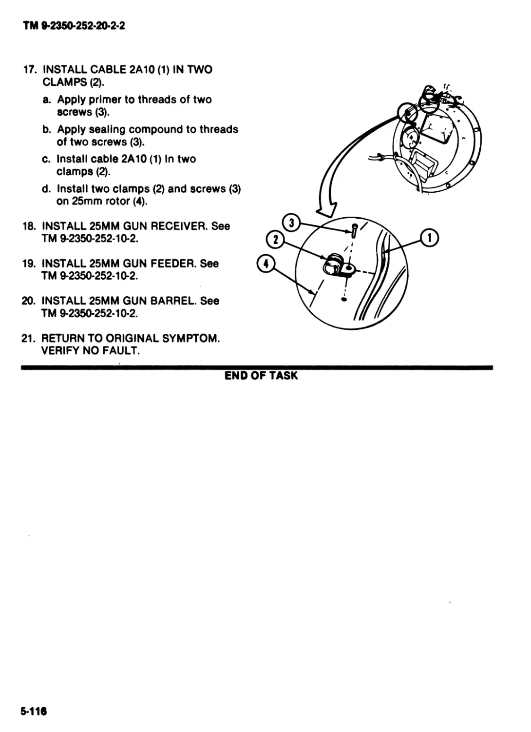
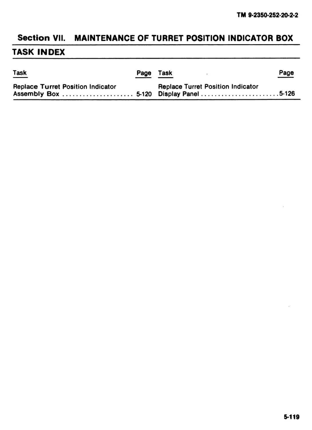
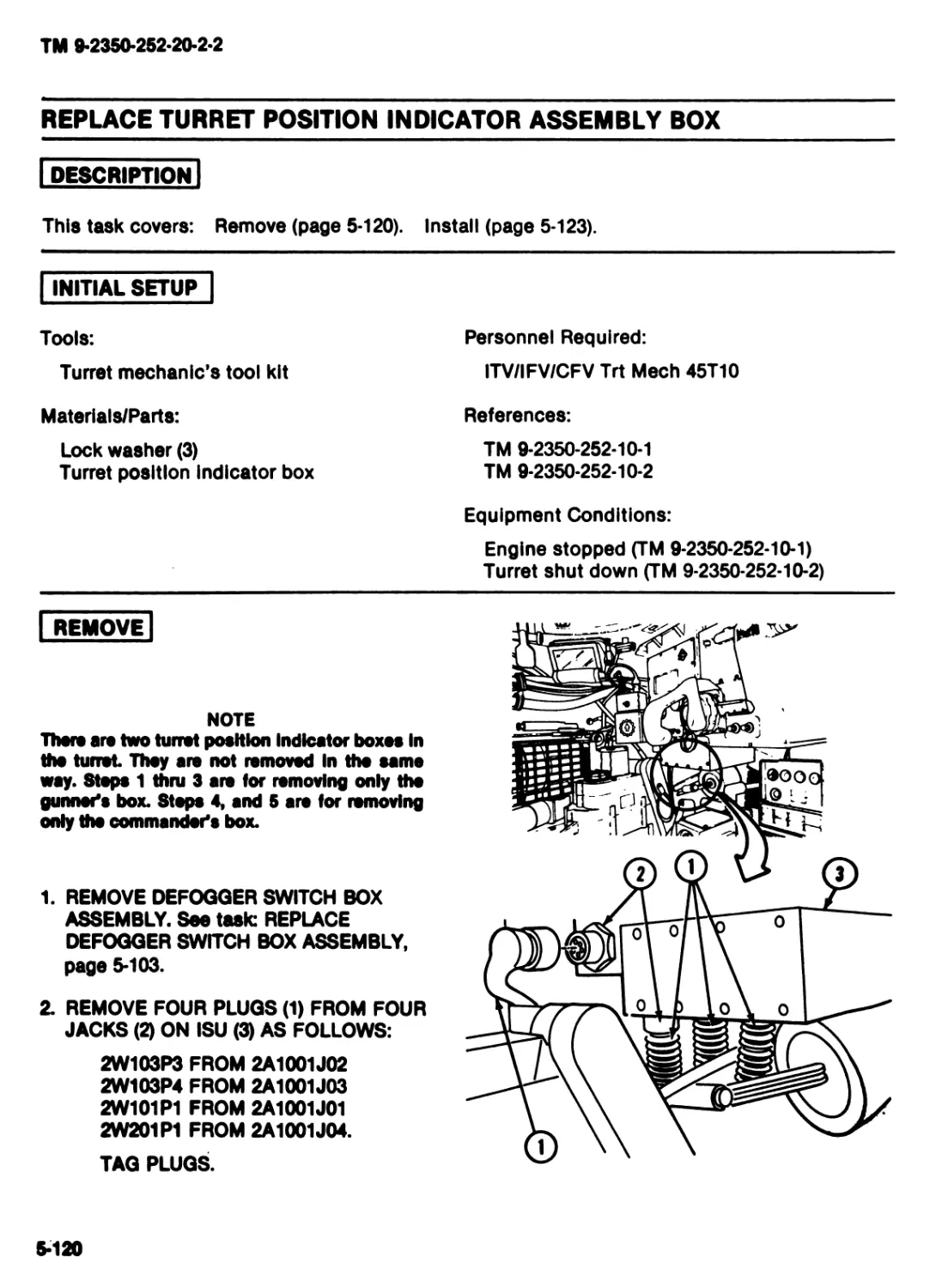
/


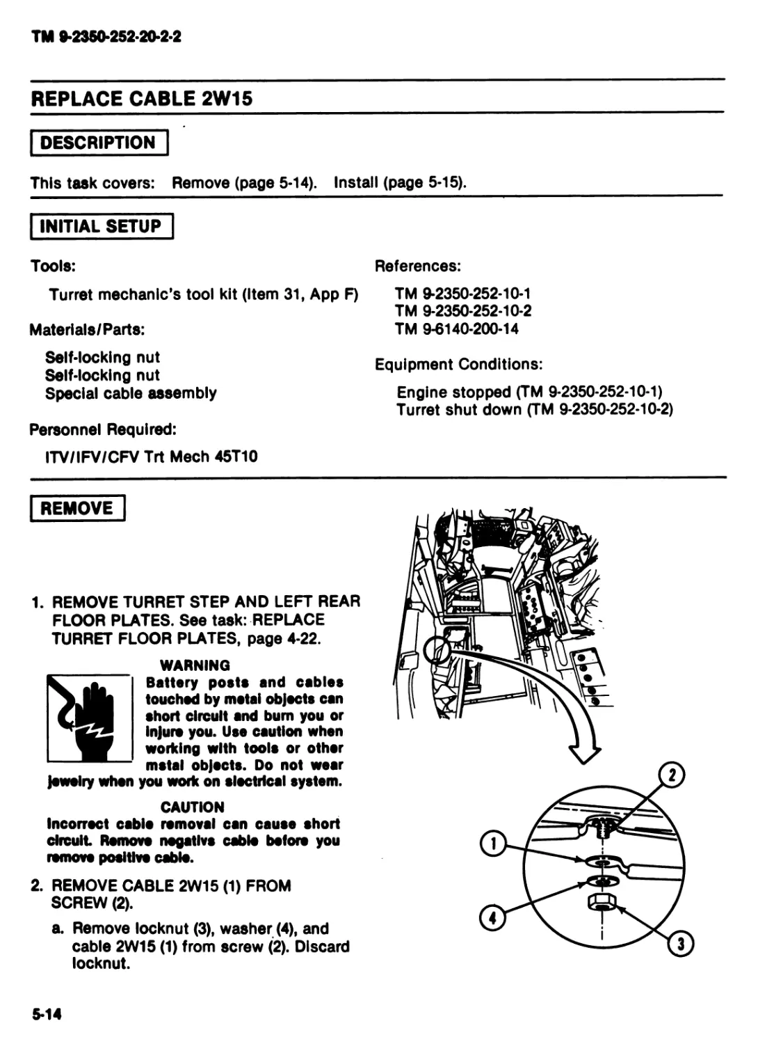


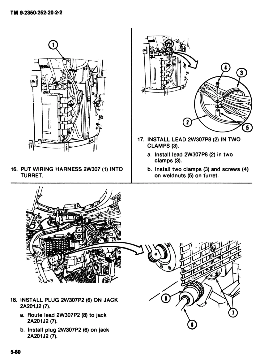
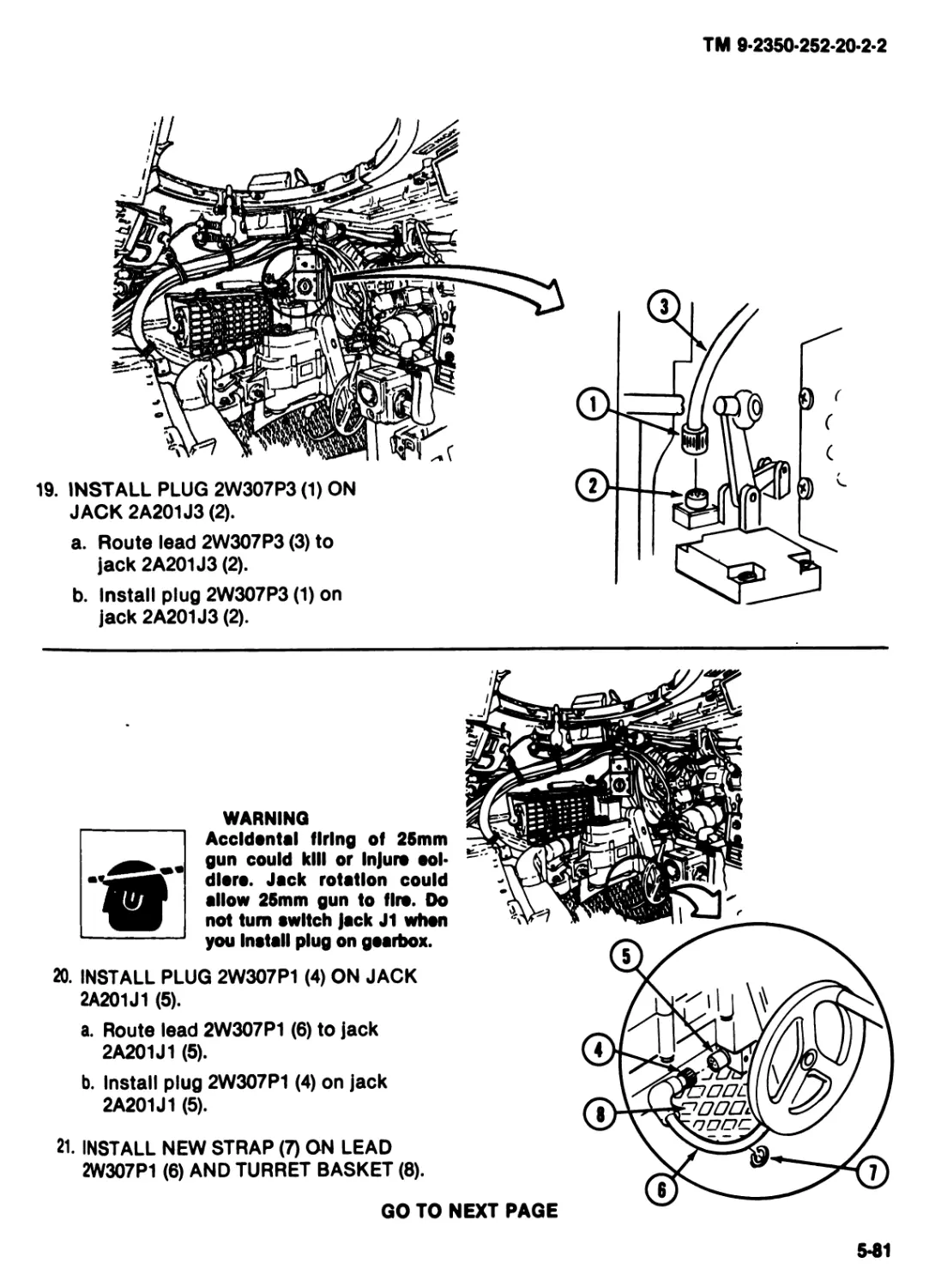
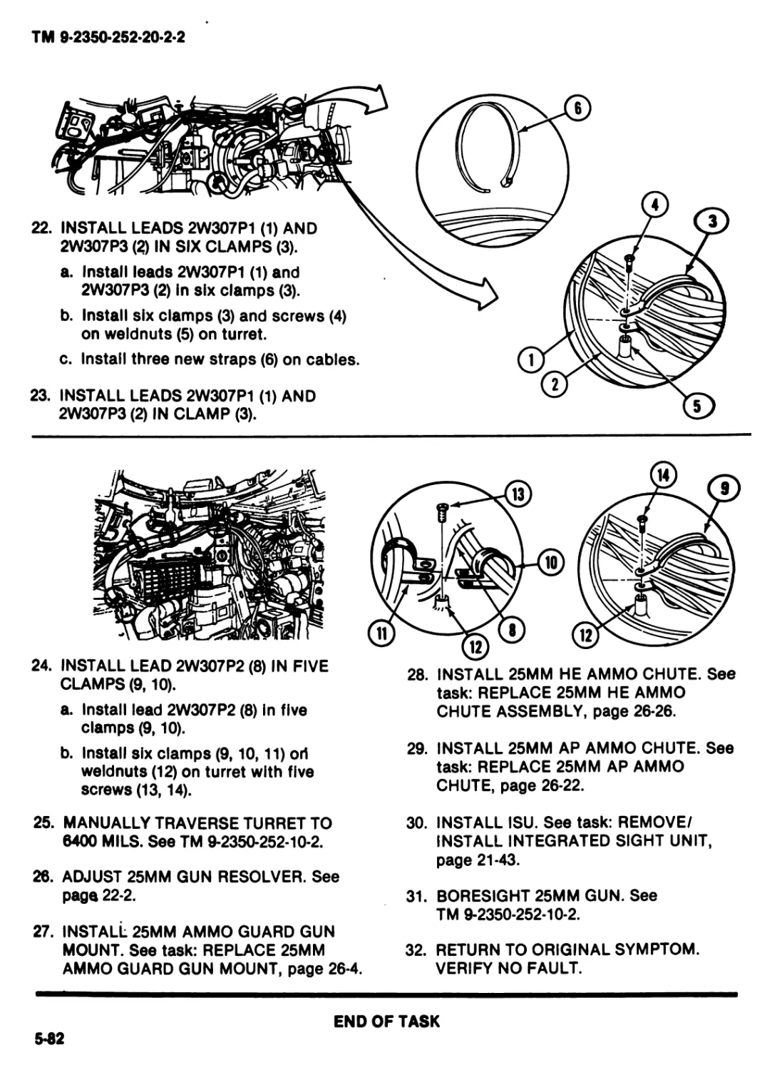
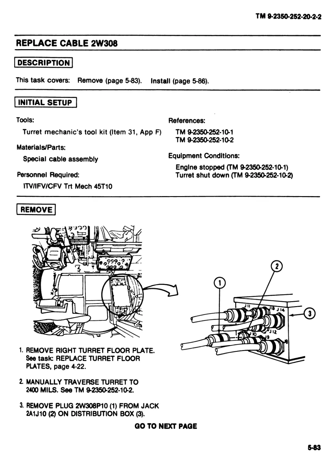
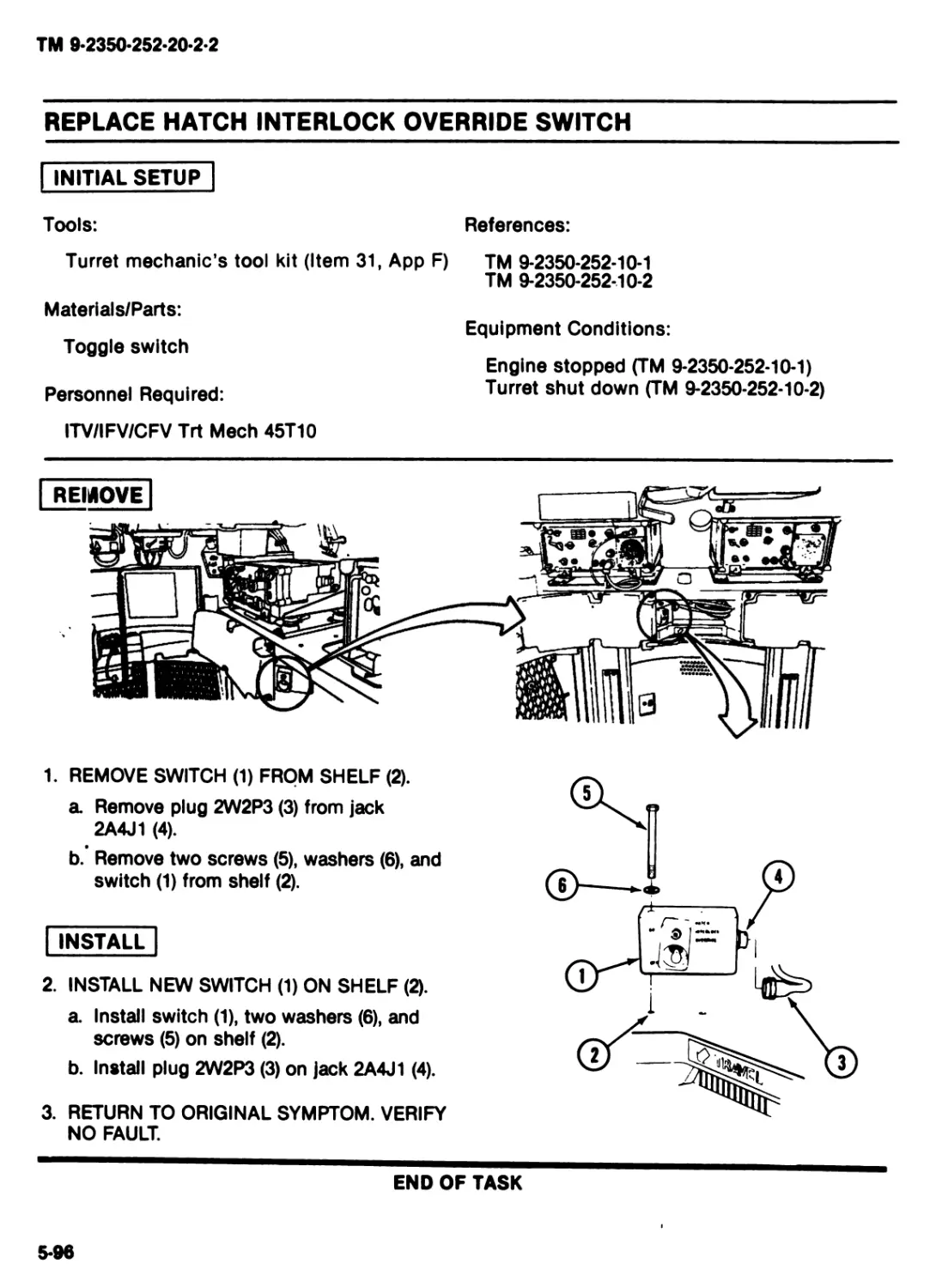
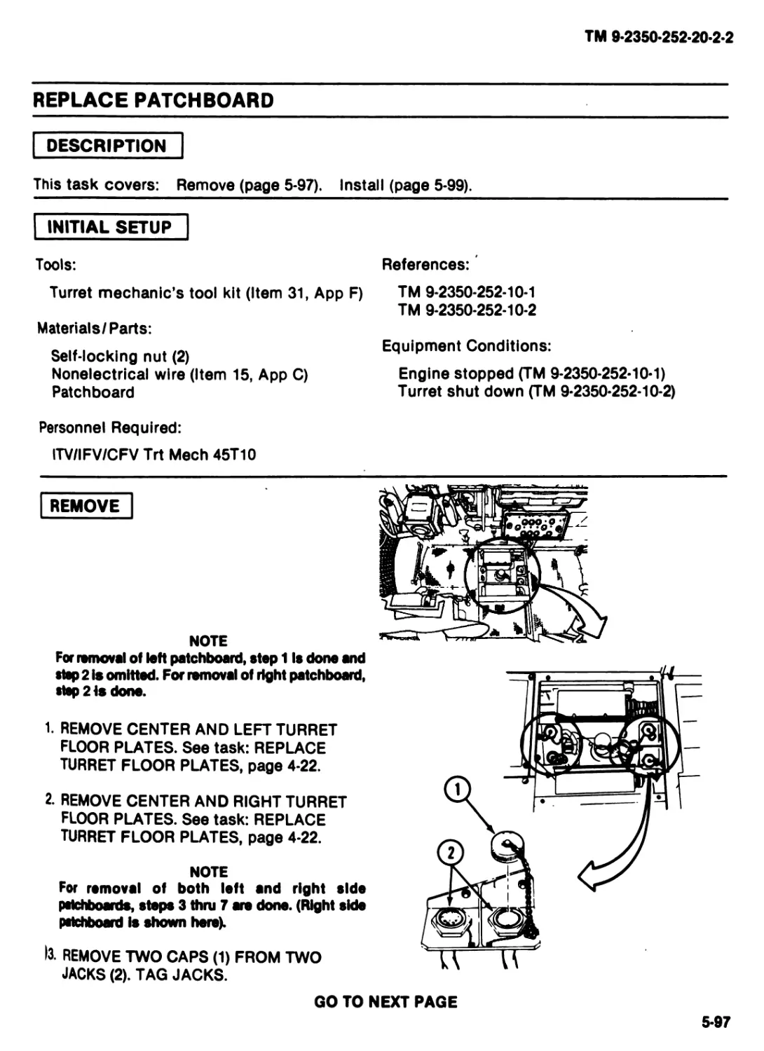
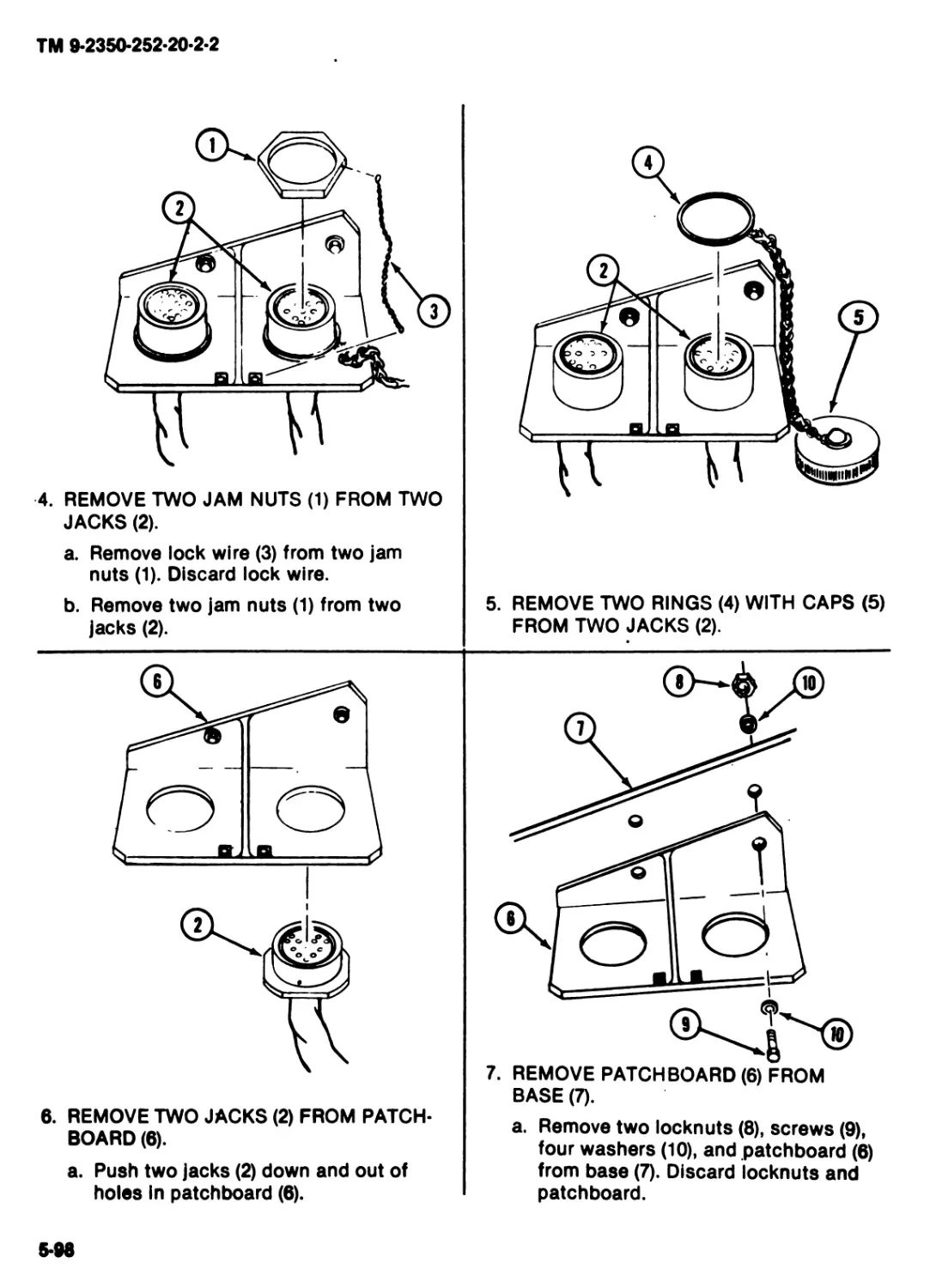
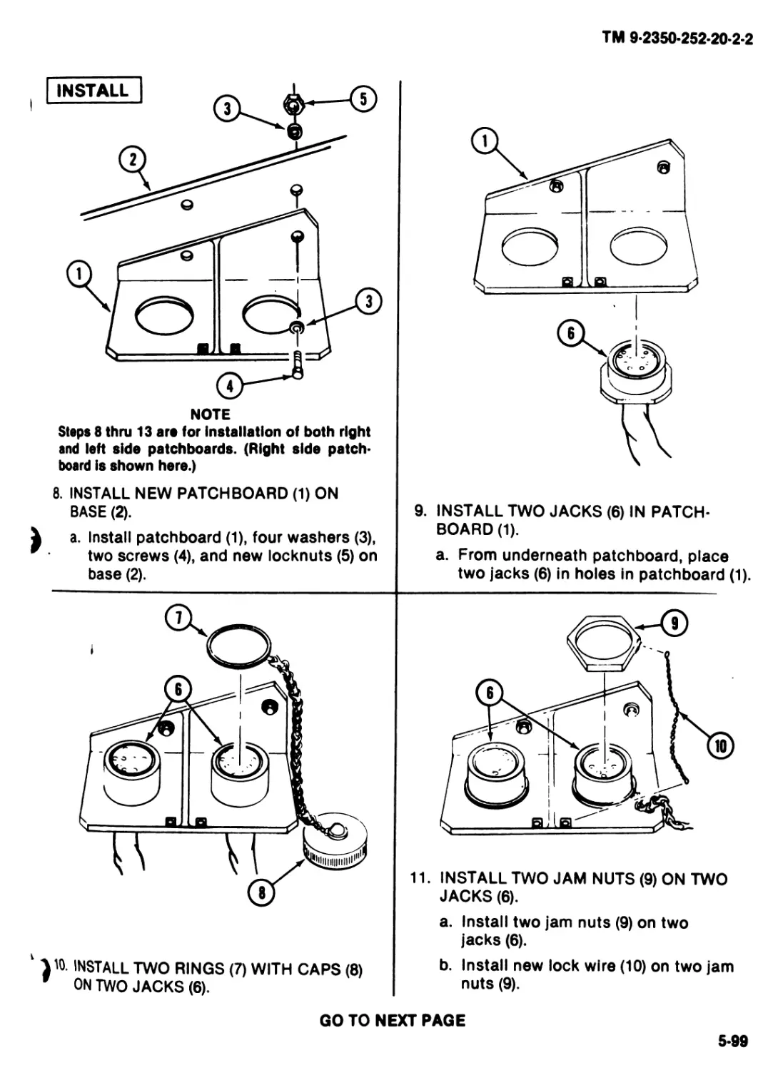


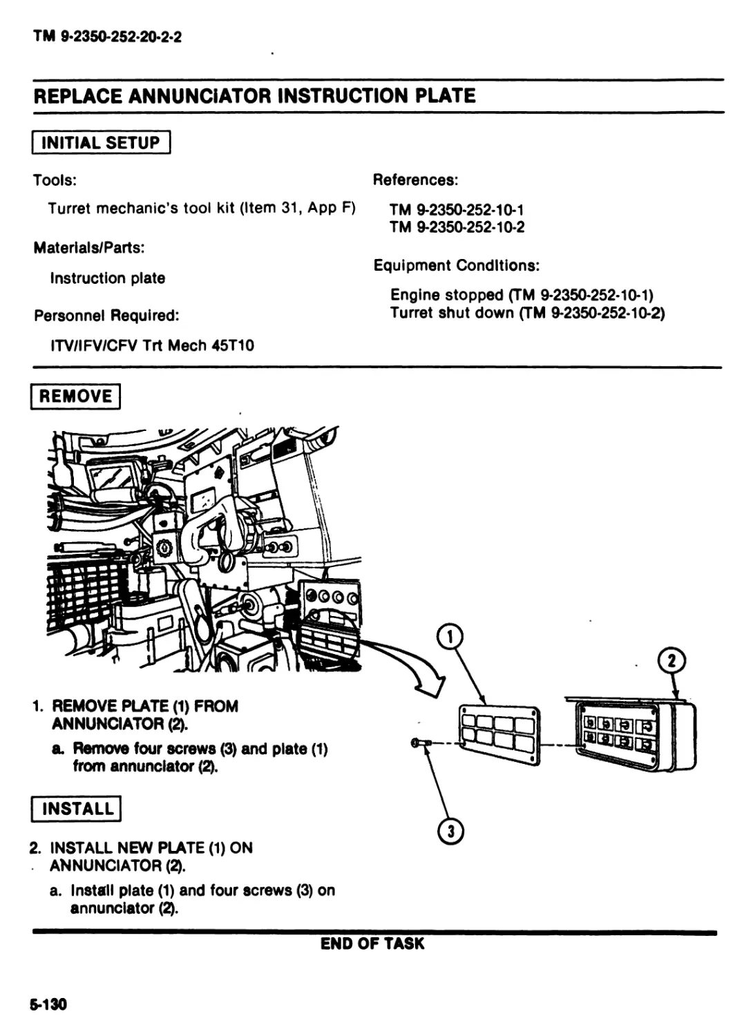

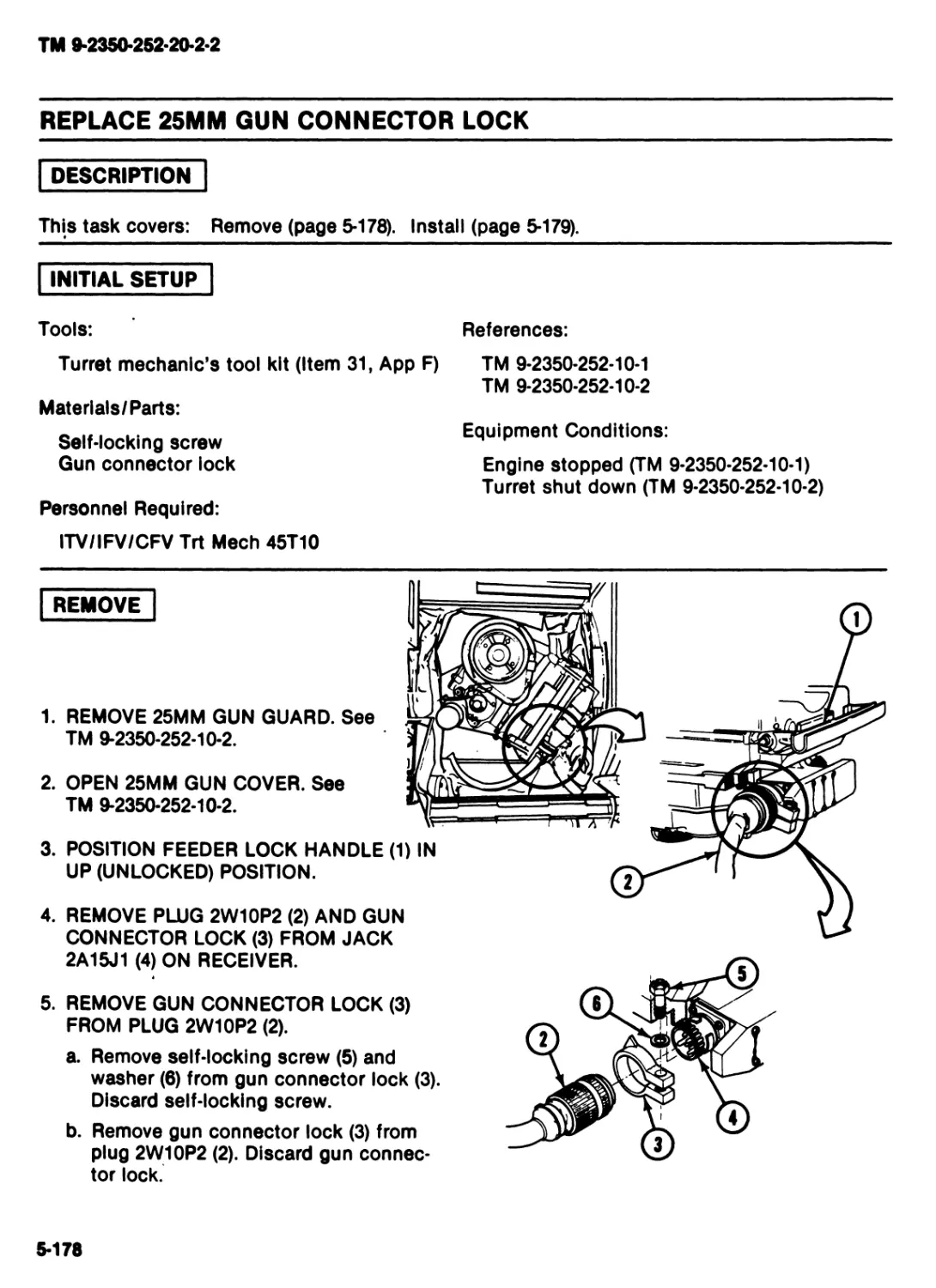
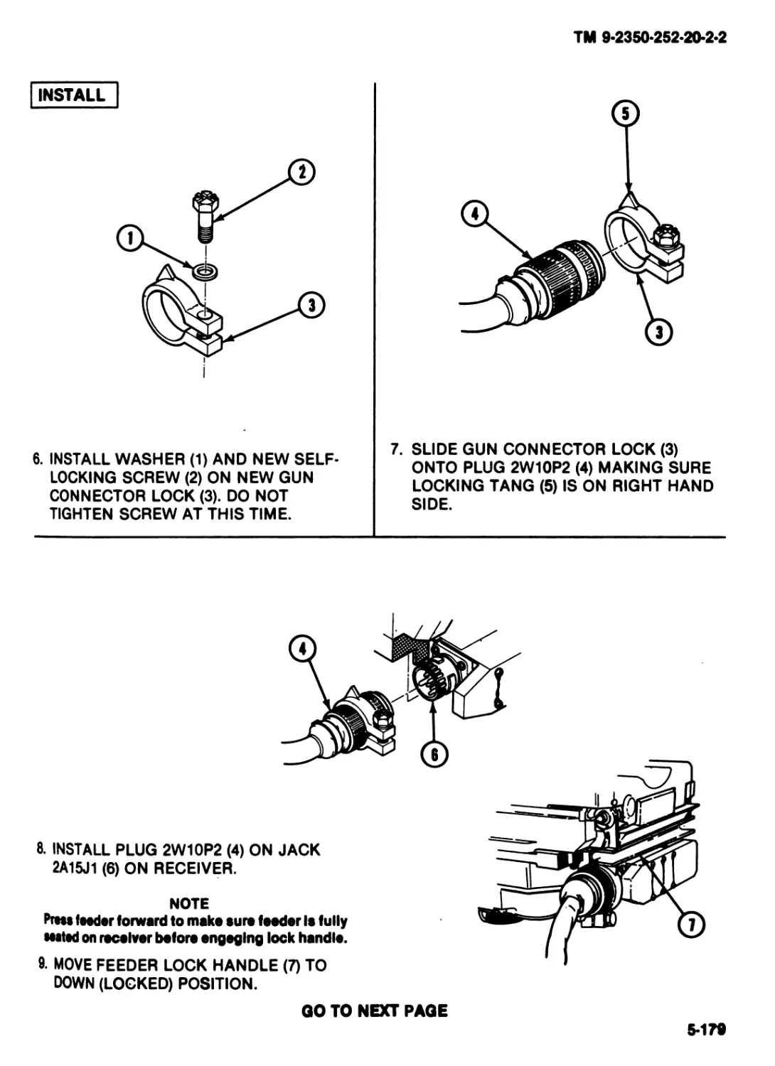

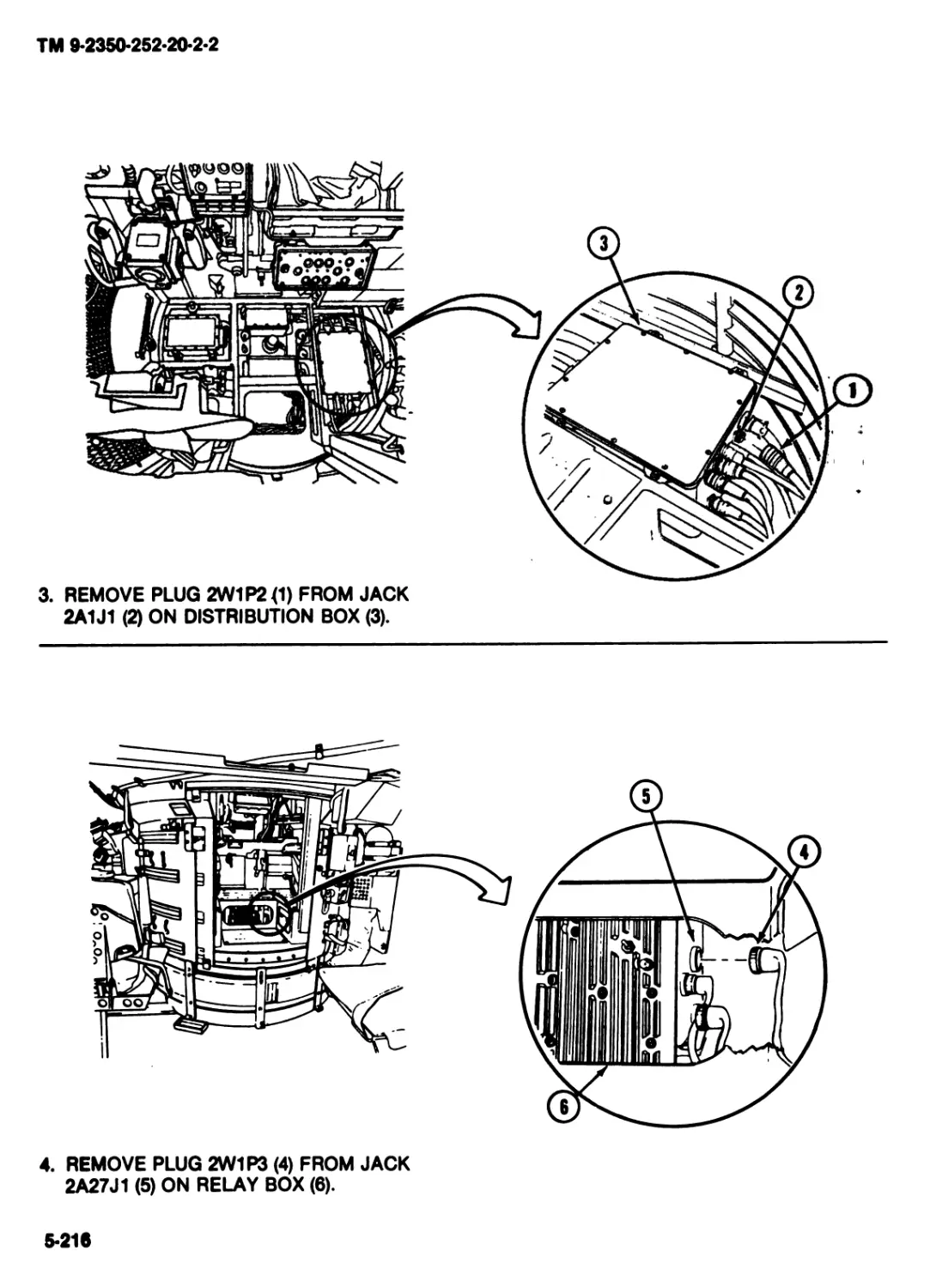
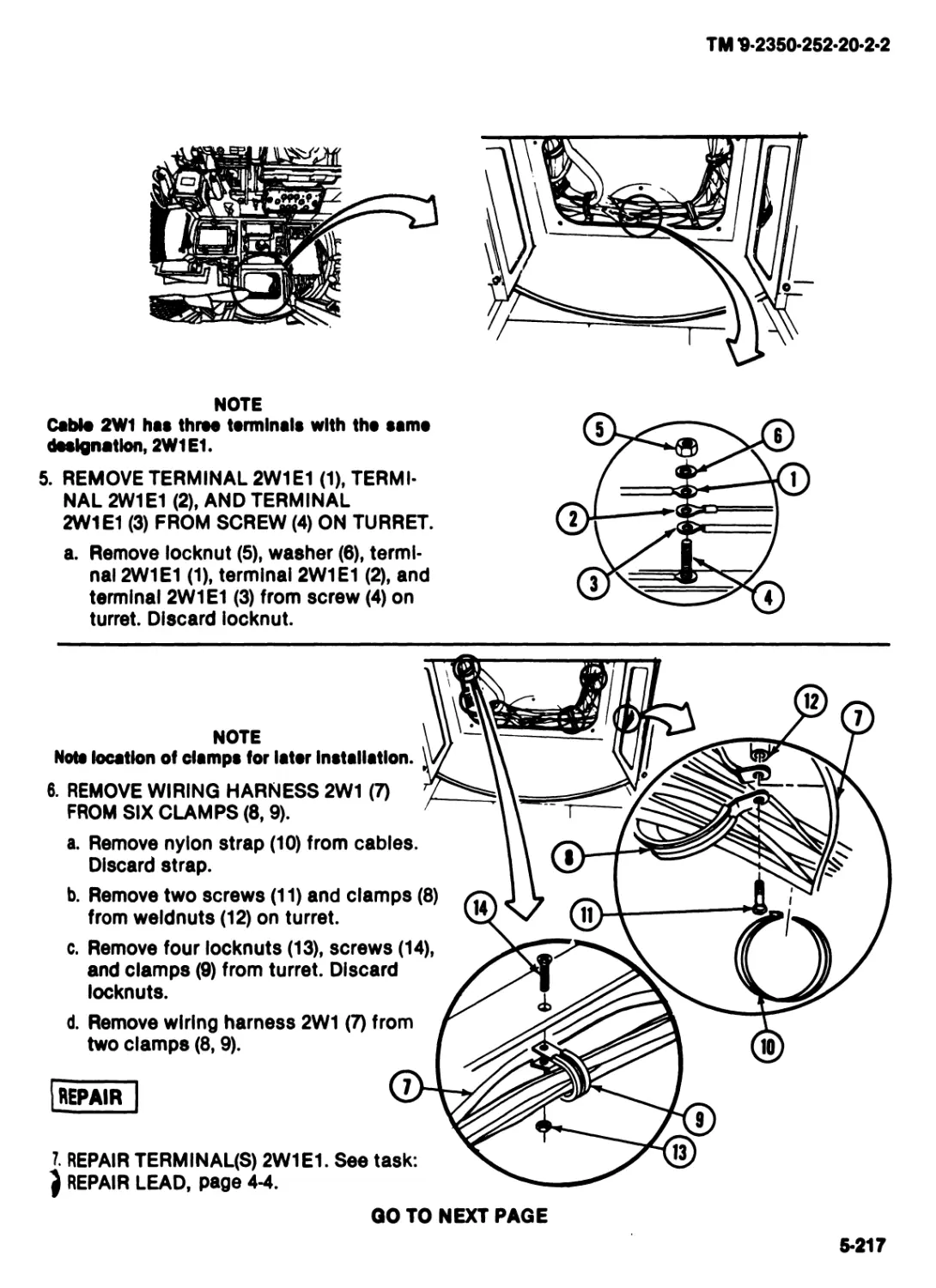
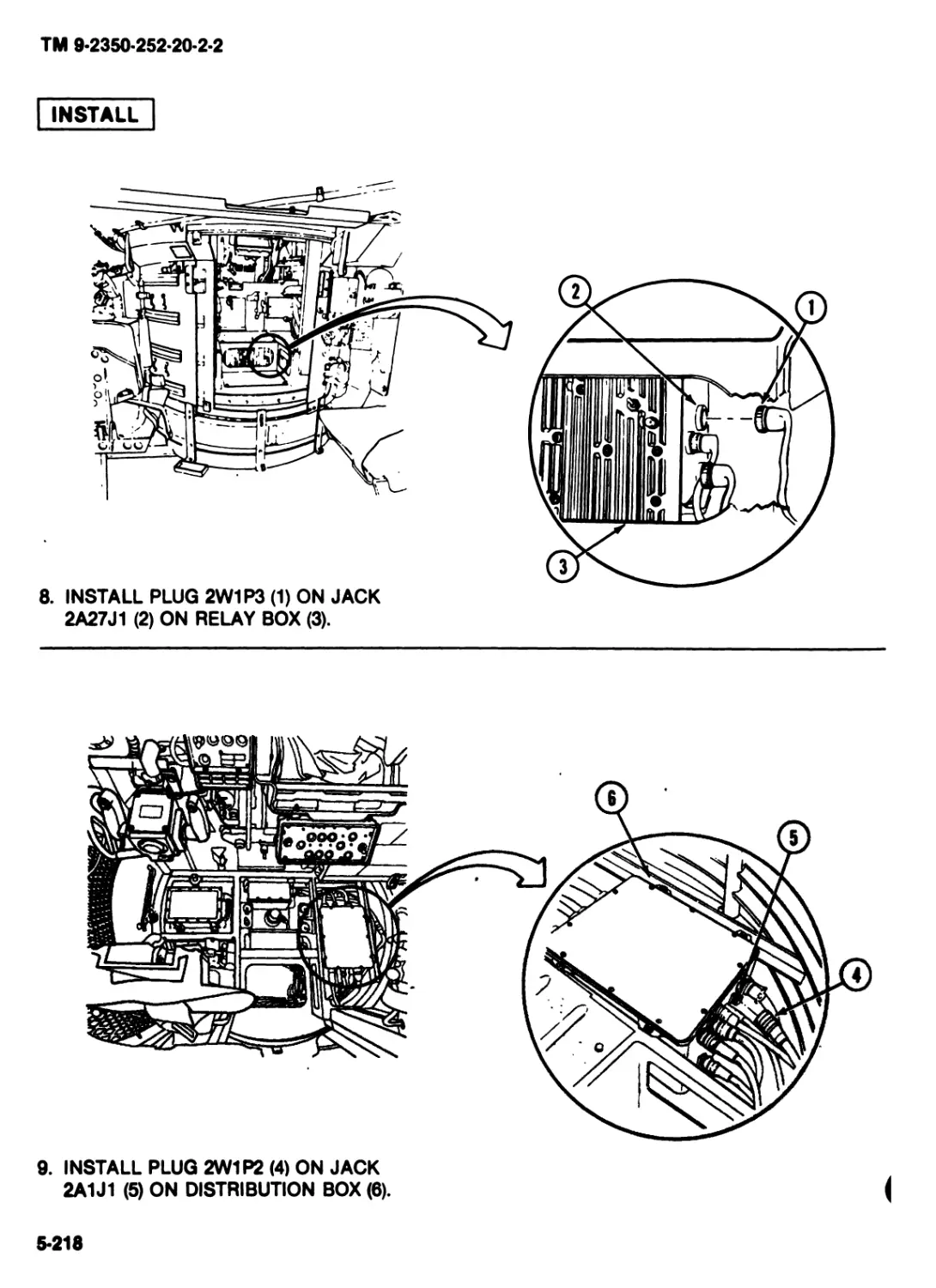
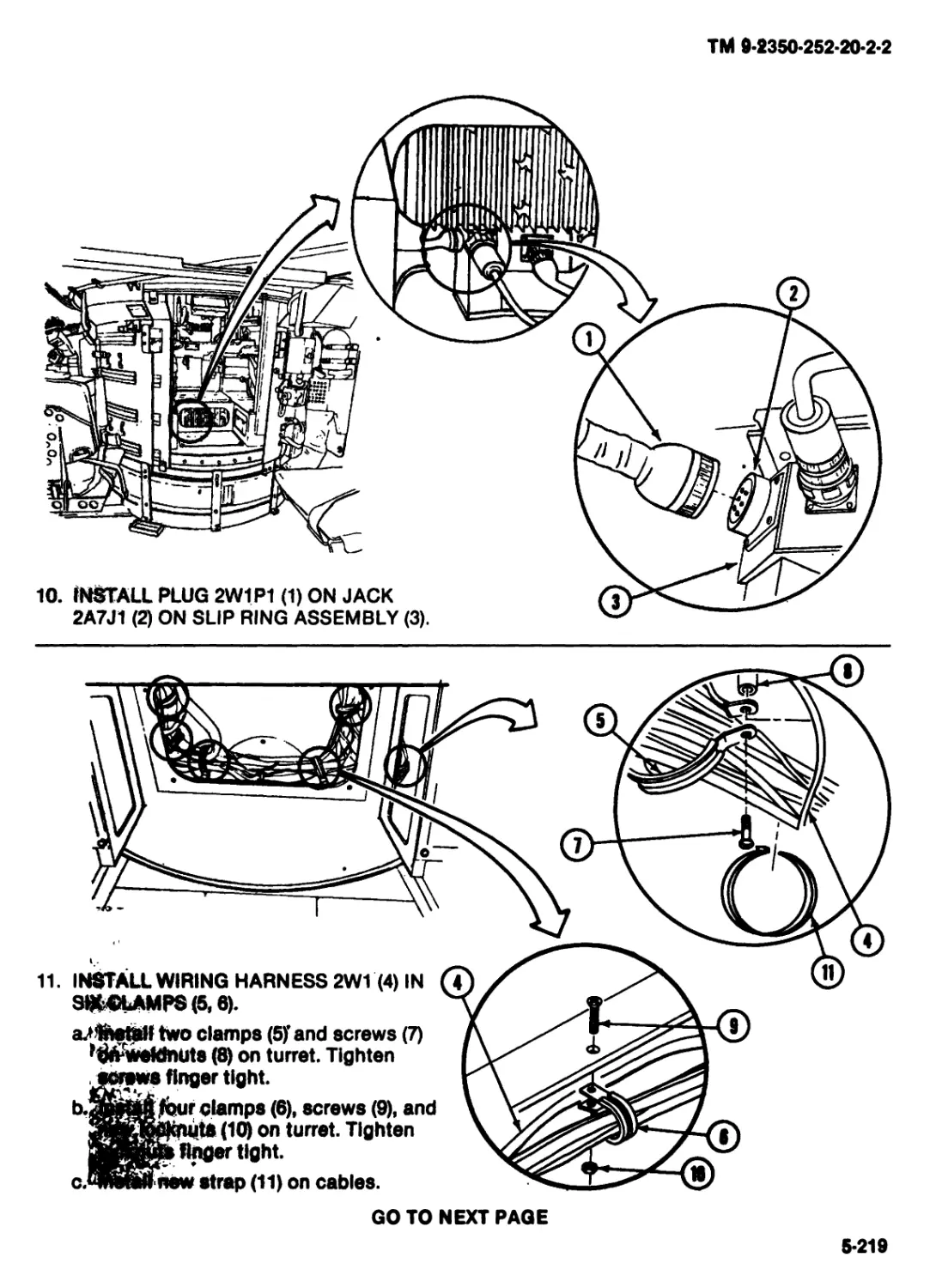
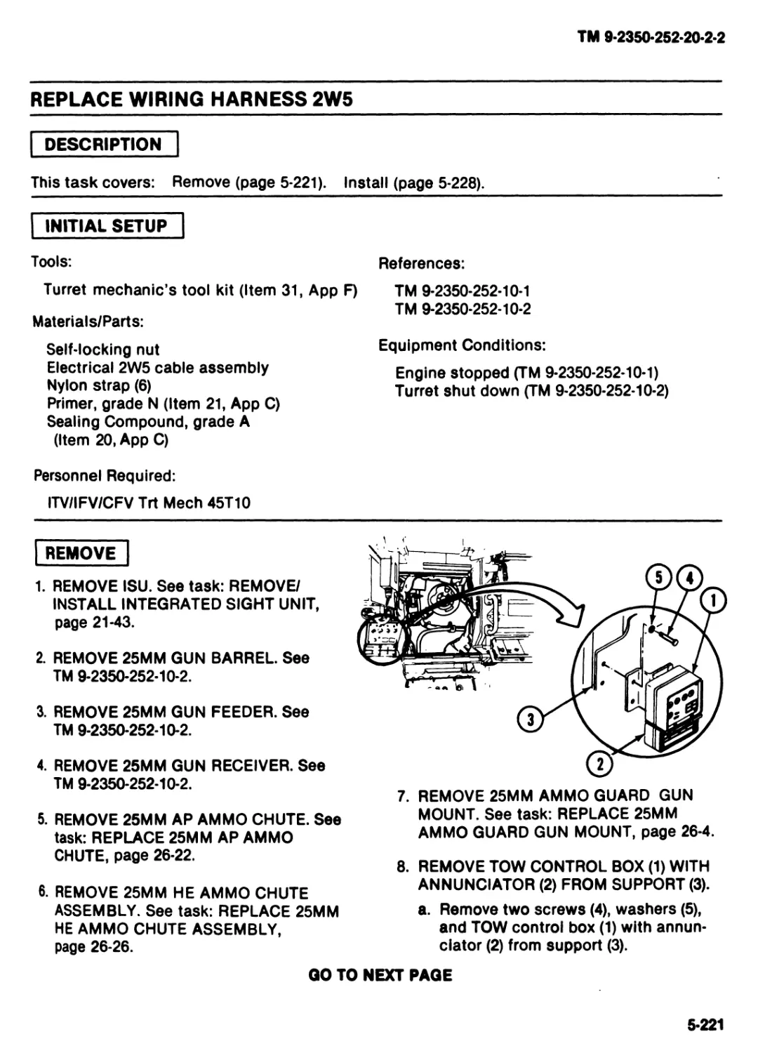

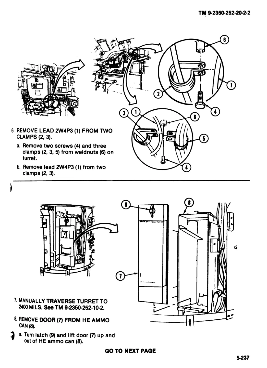
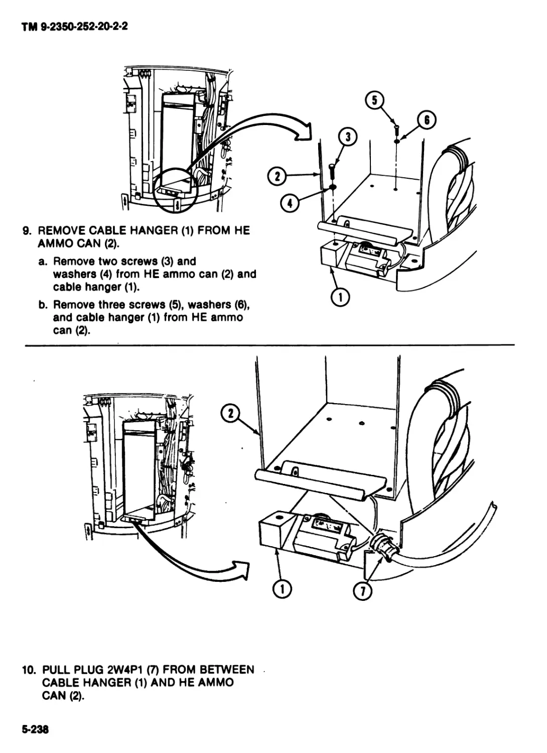
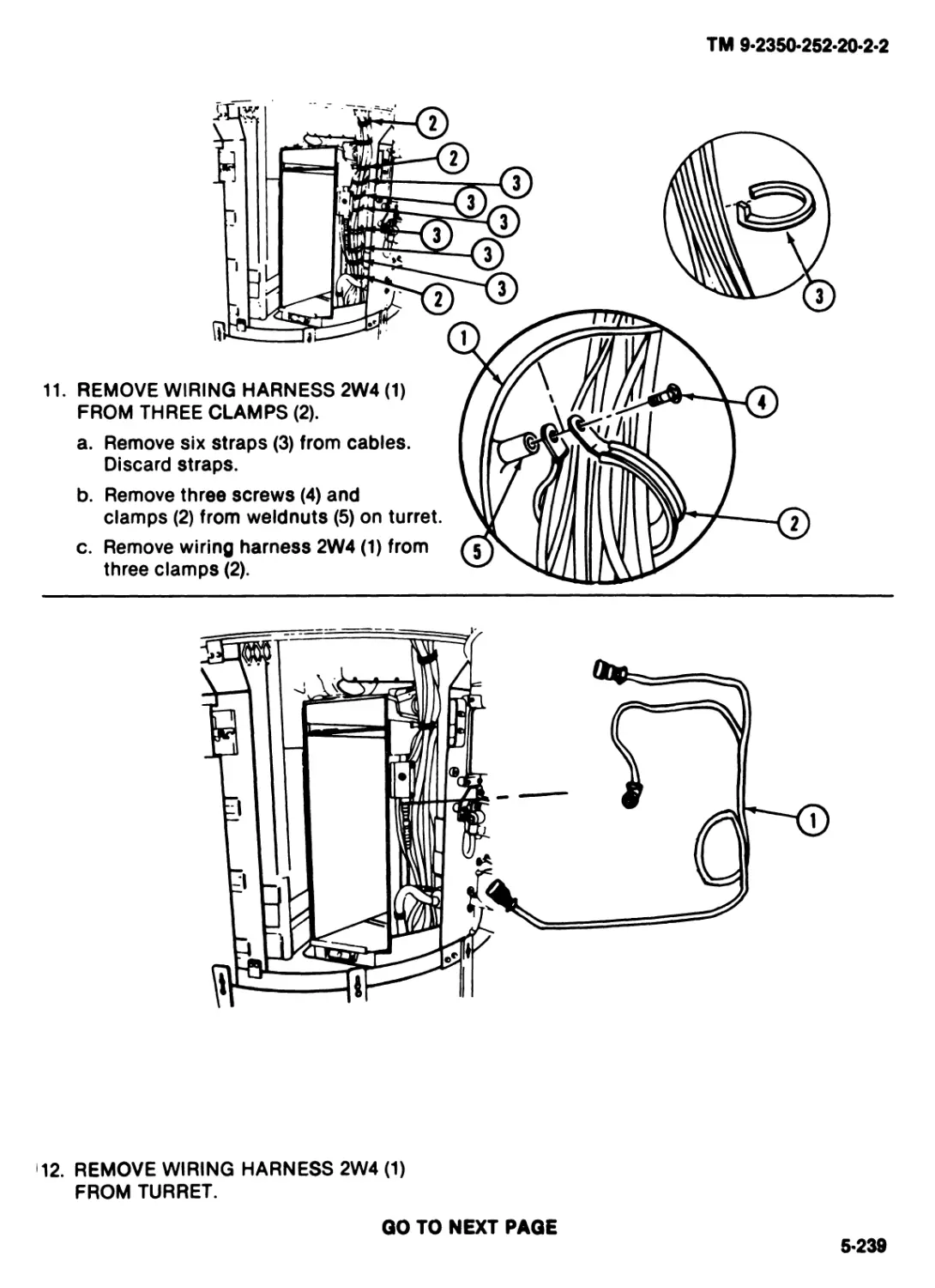
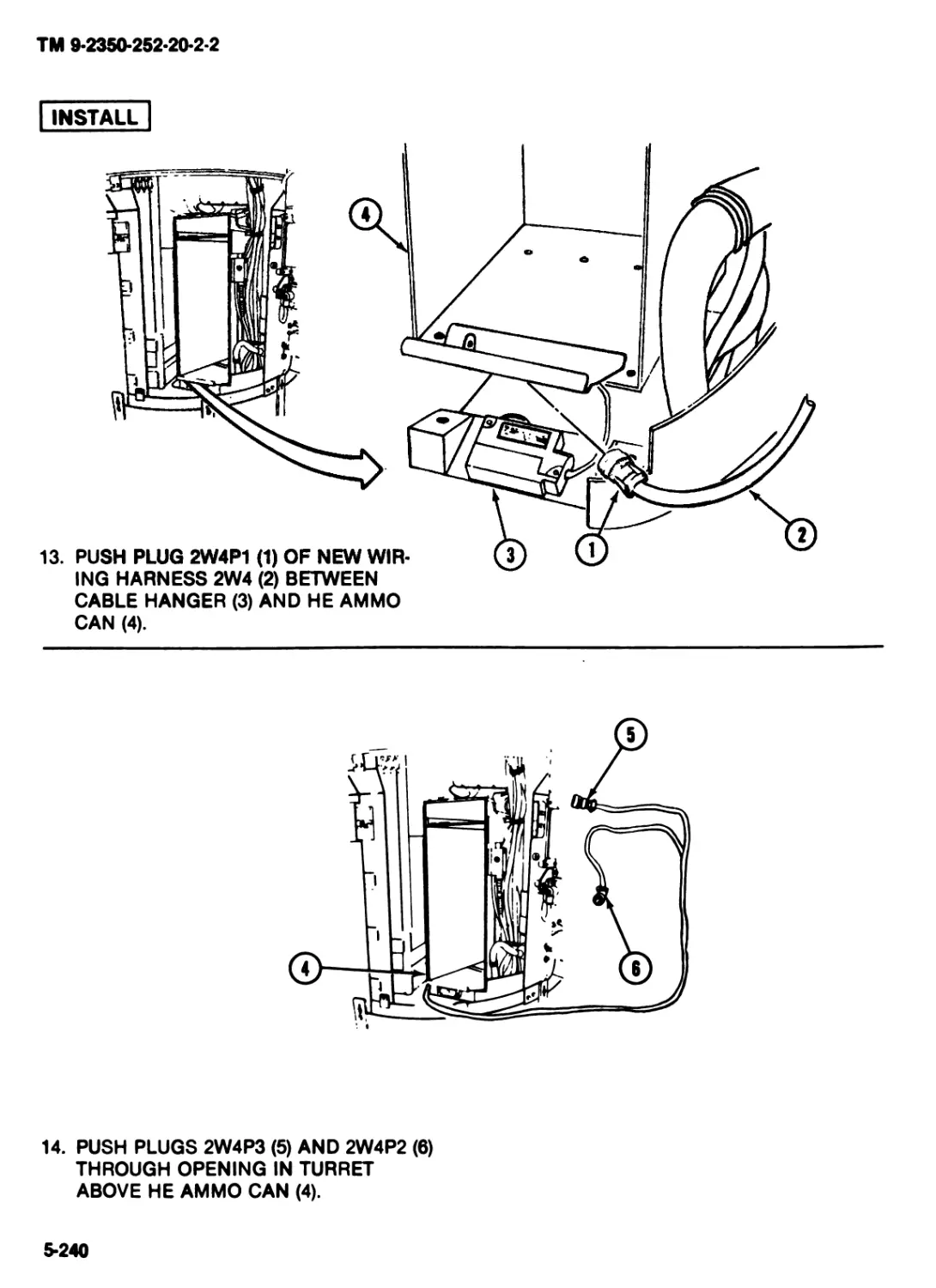


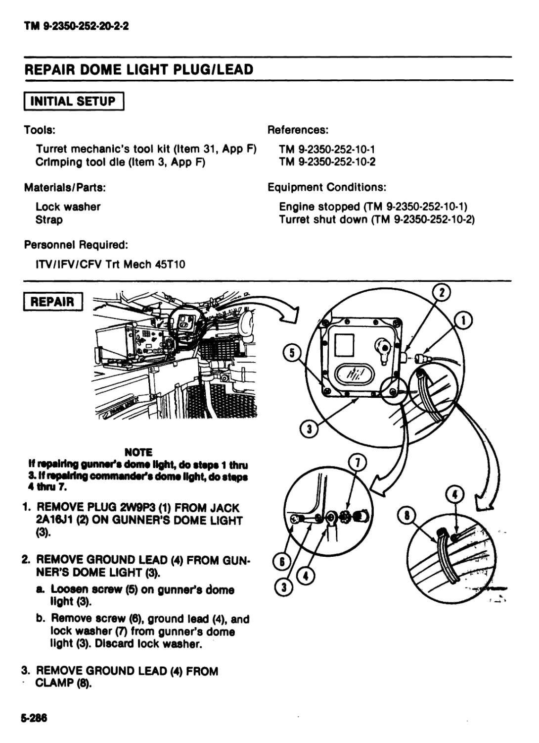
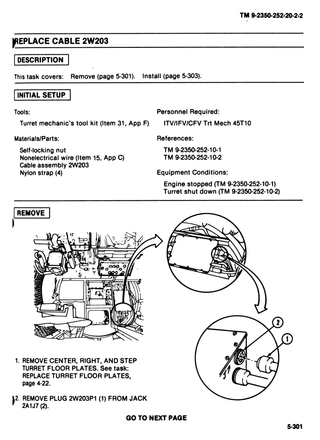

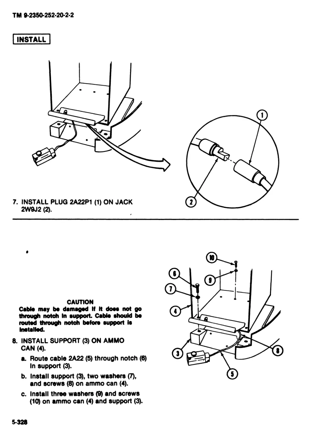
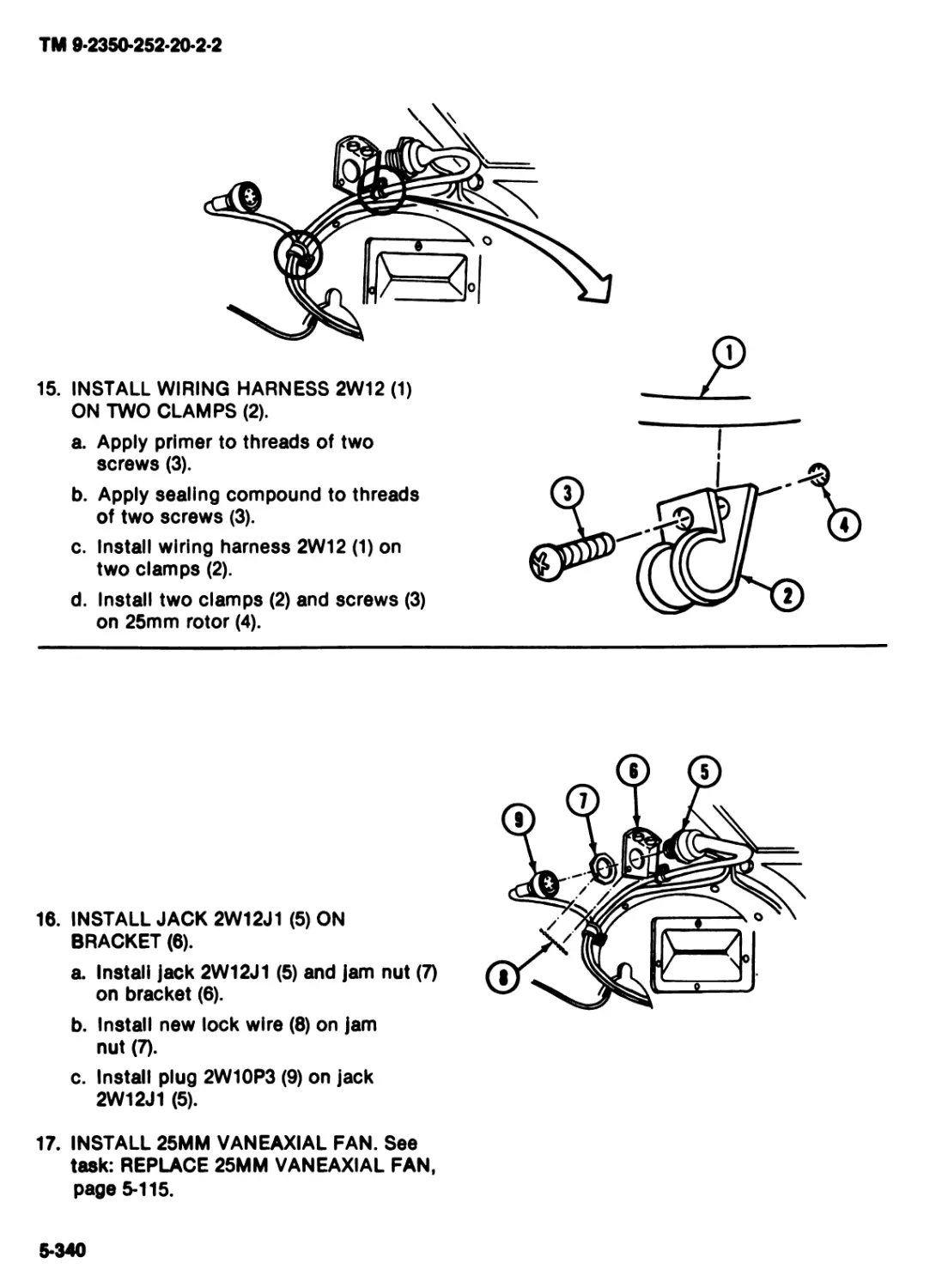
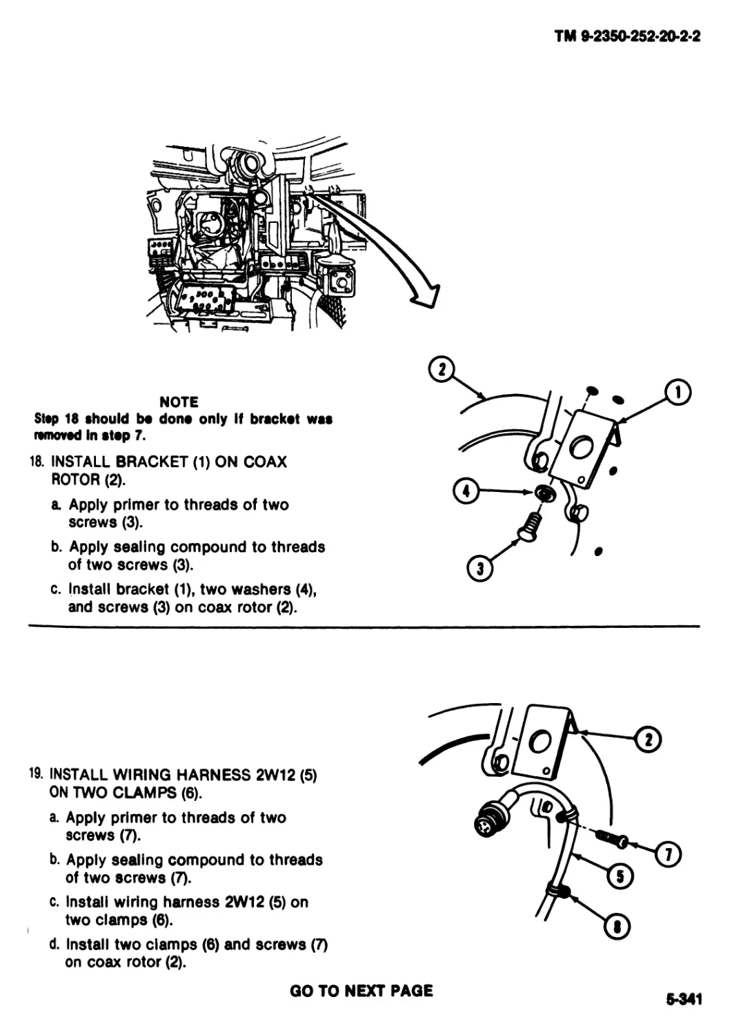
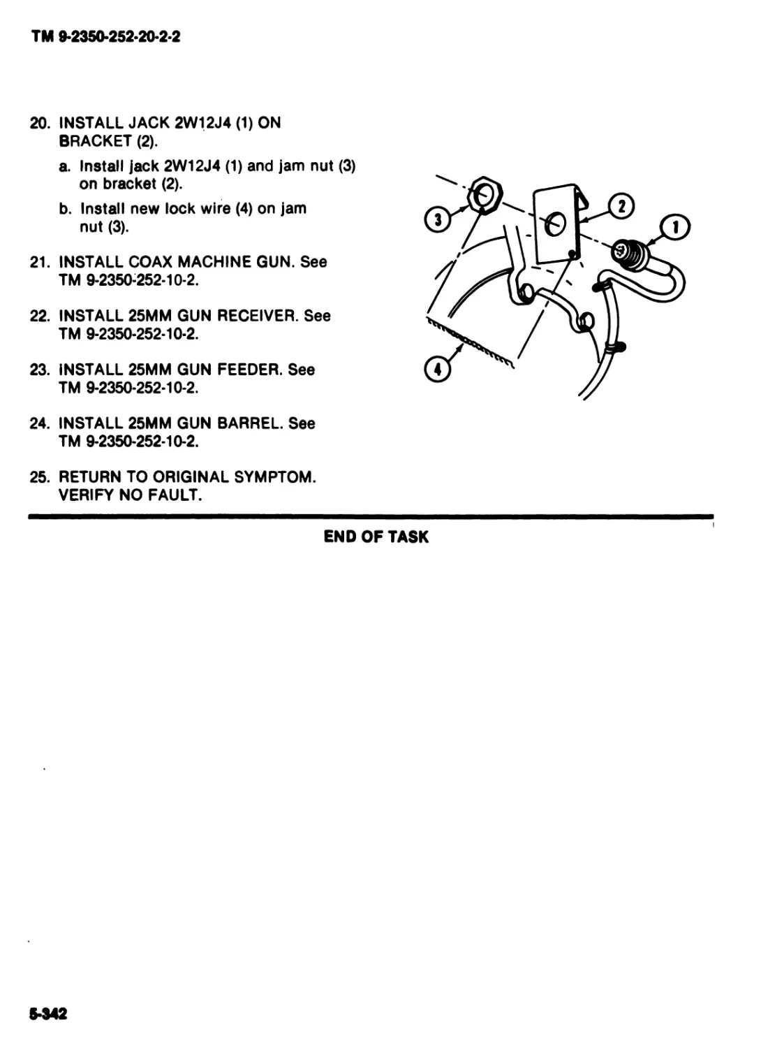
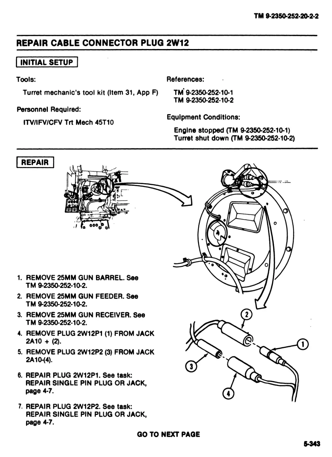
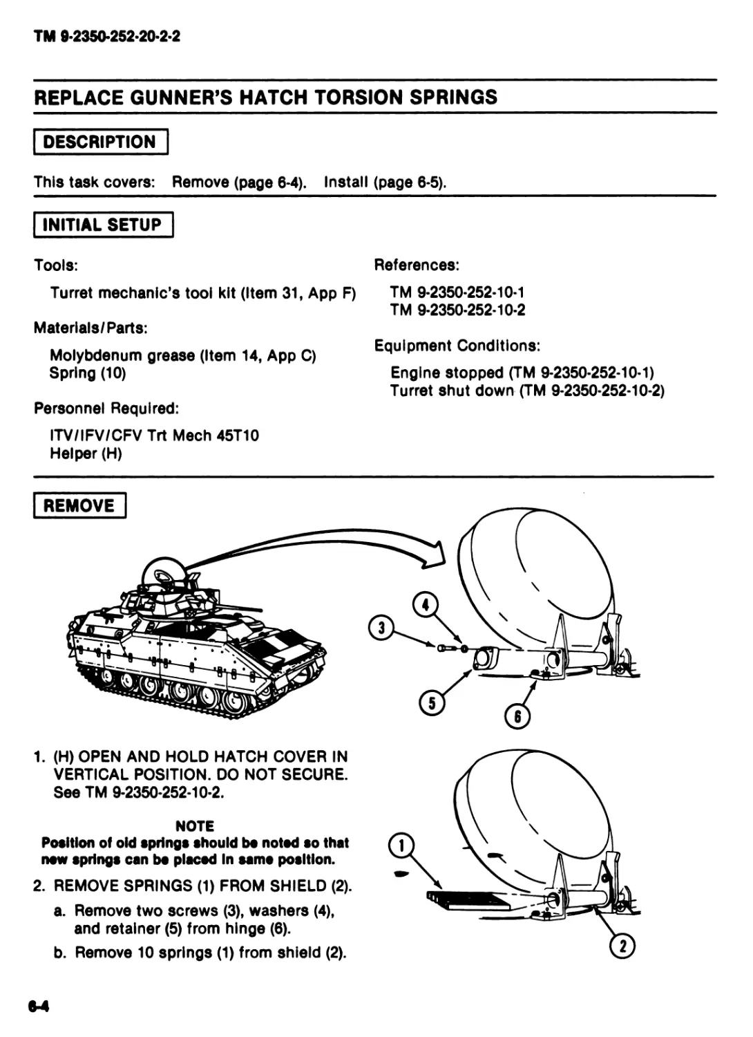
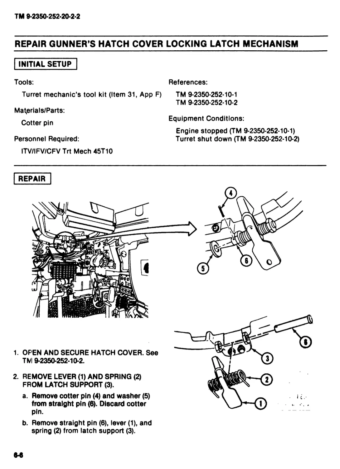
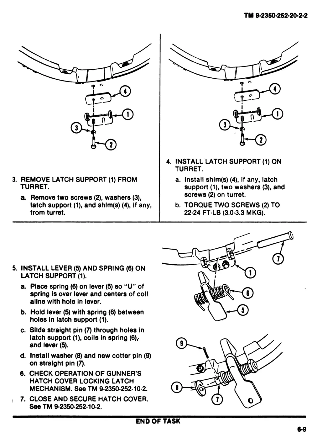
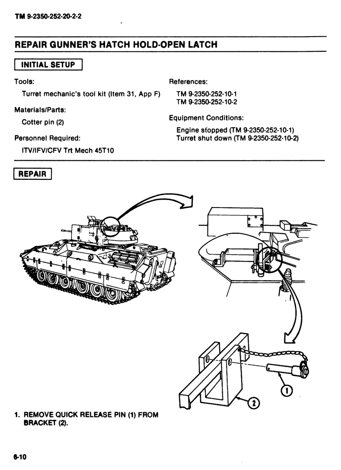
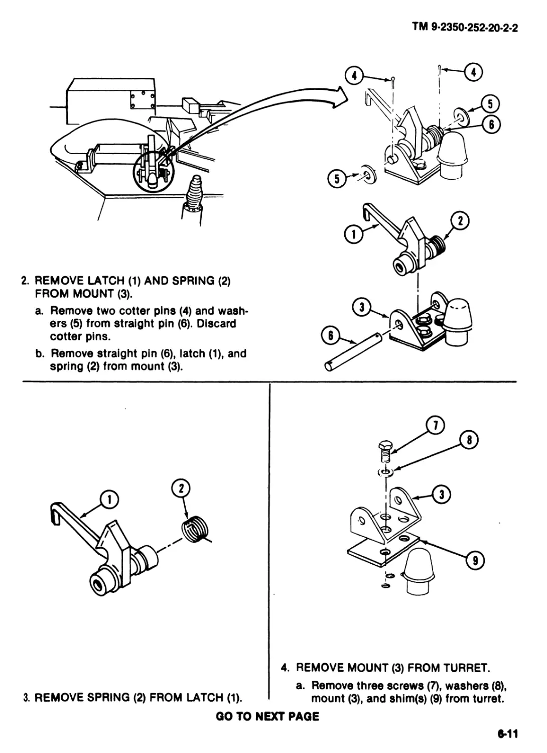
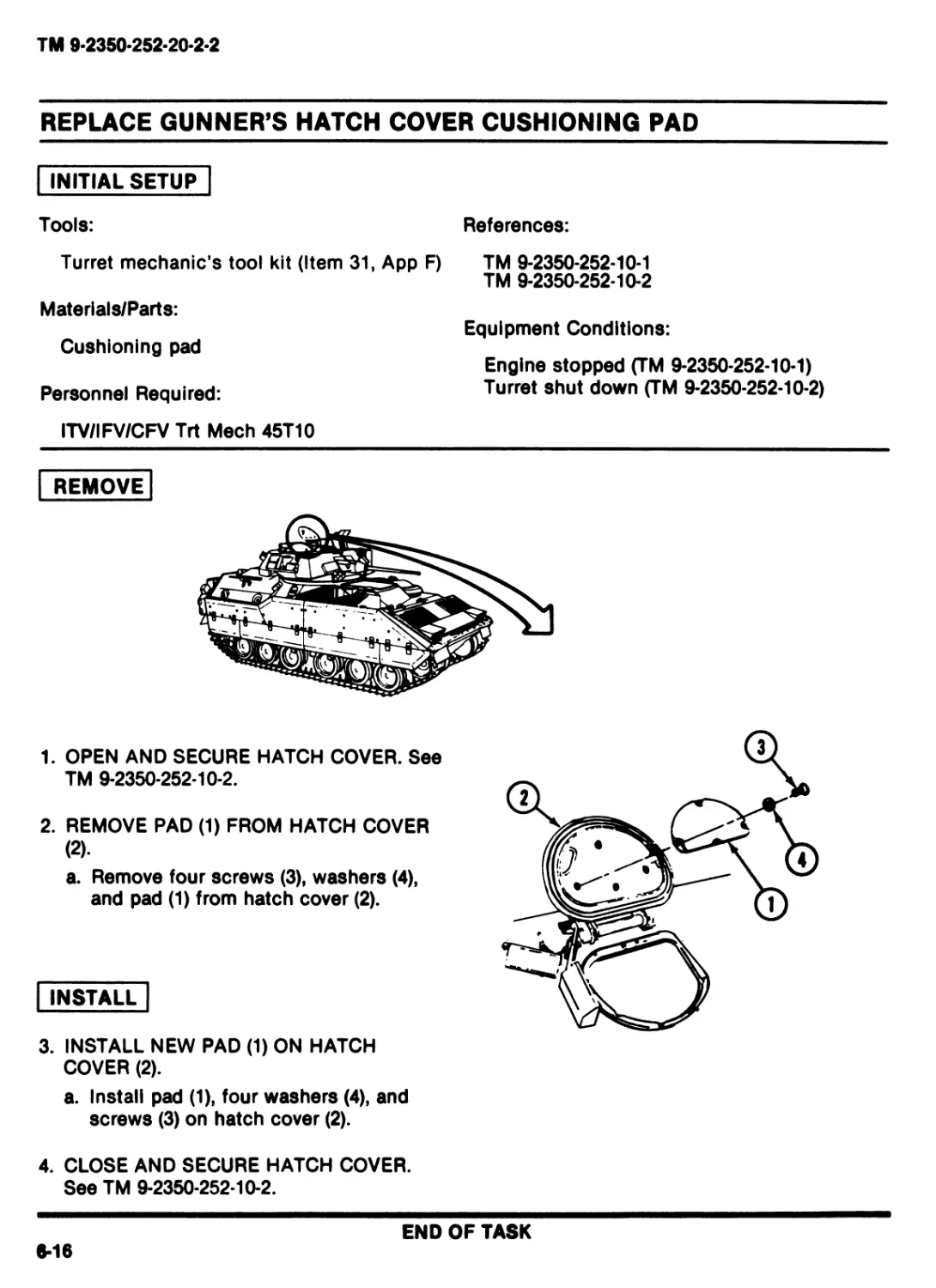
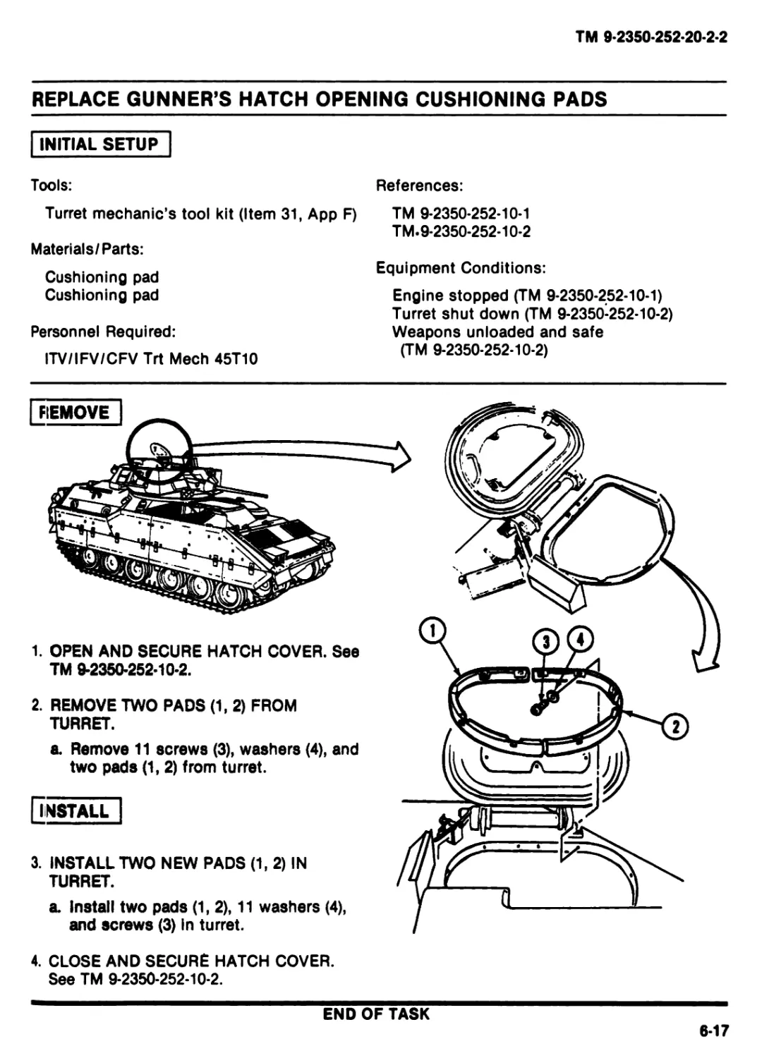
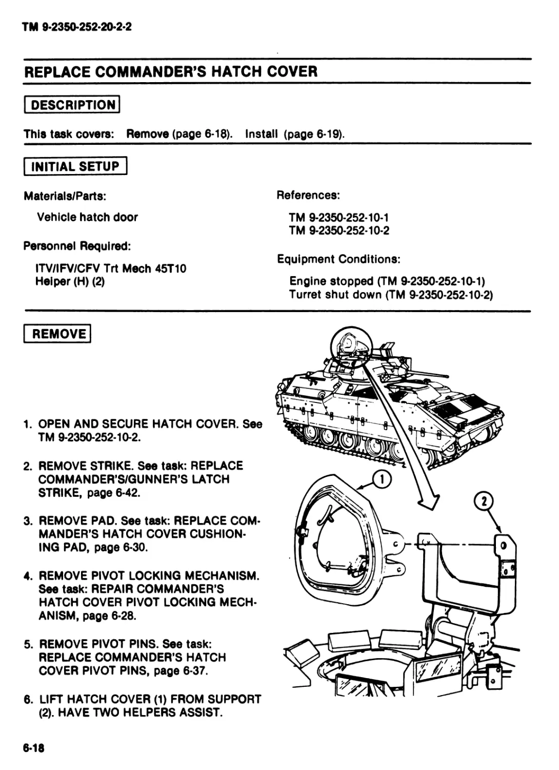
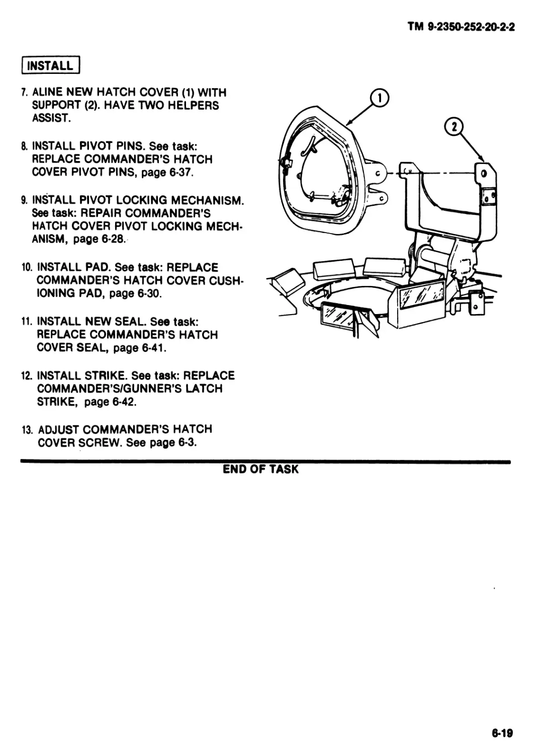
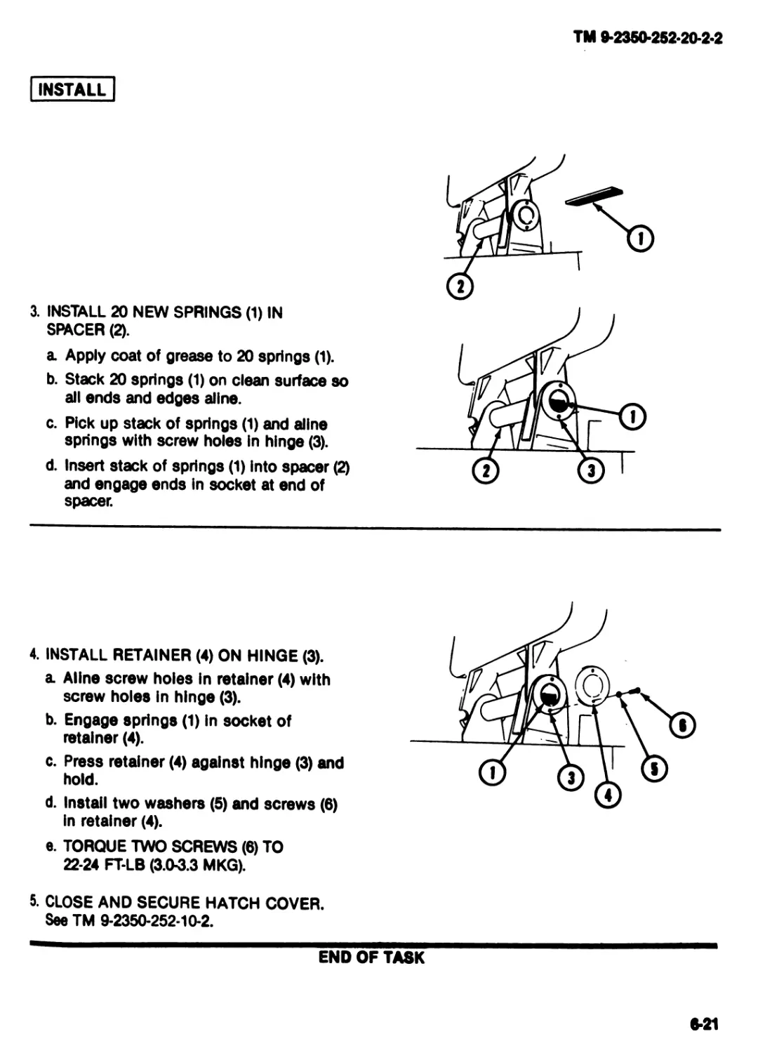
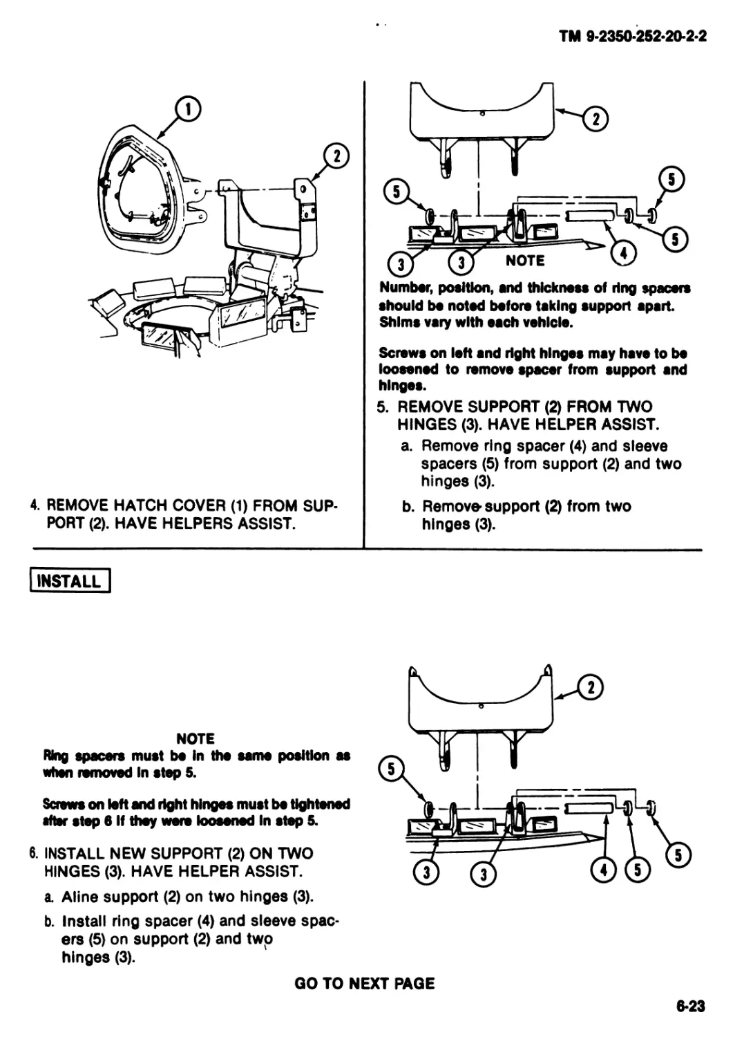
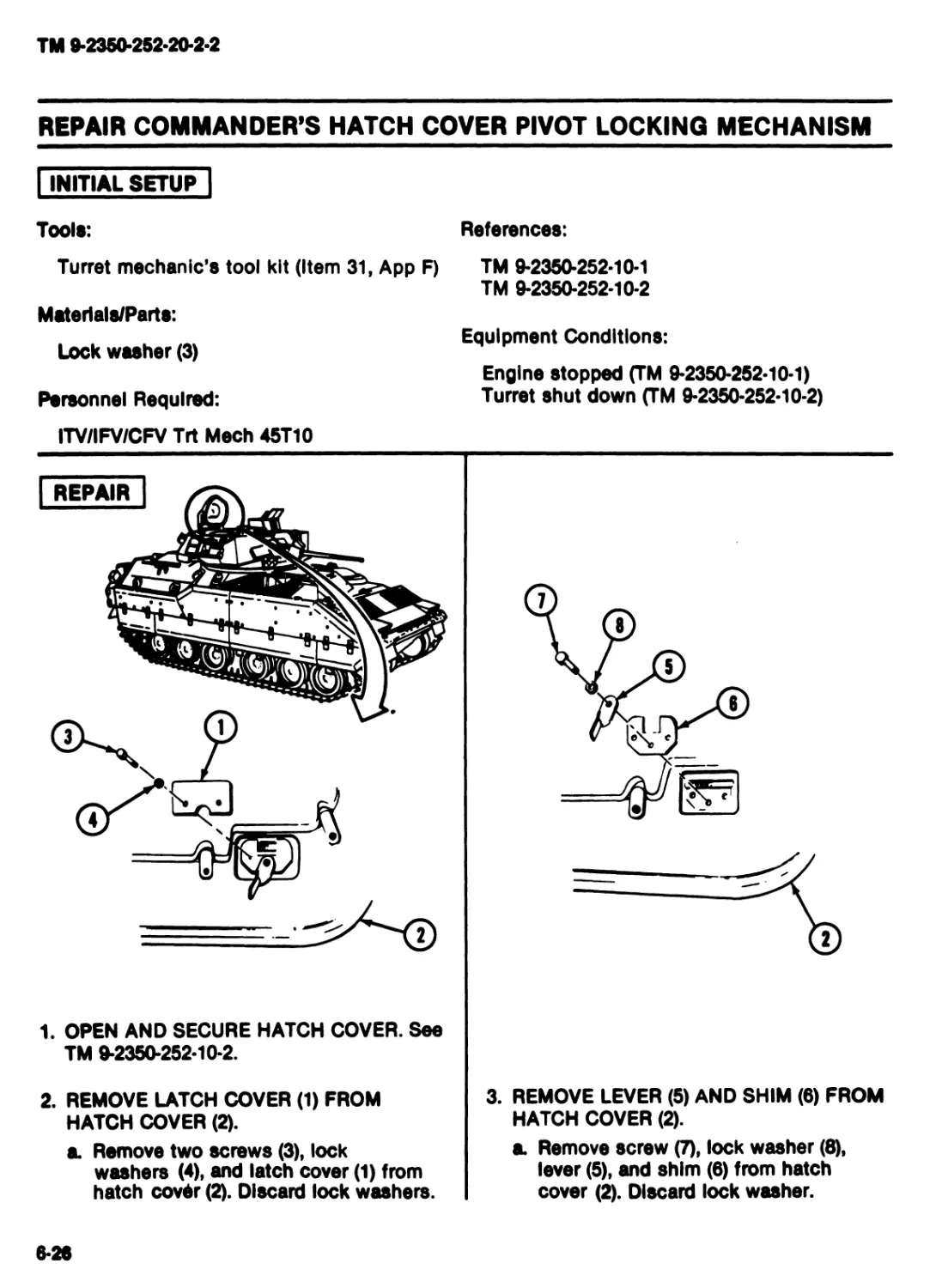
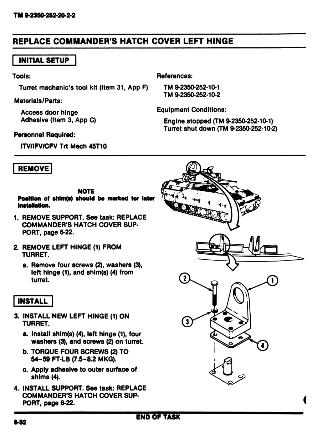
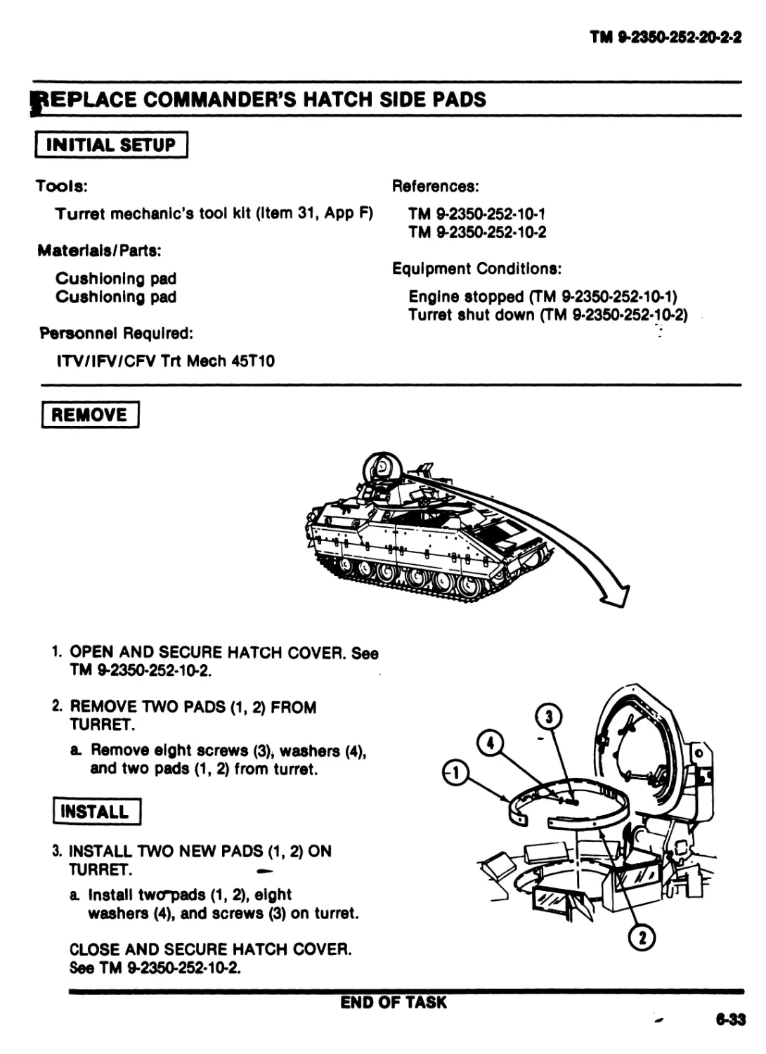
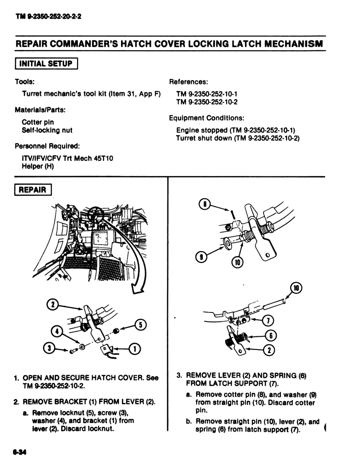
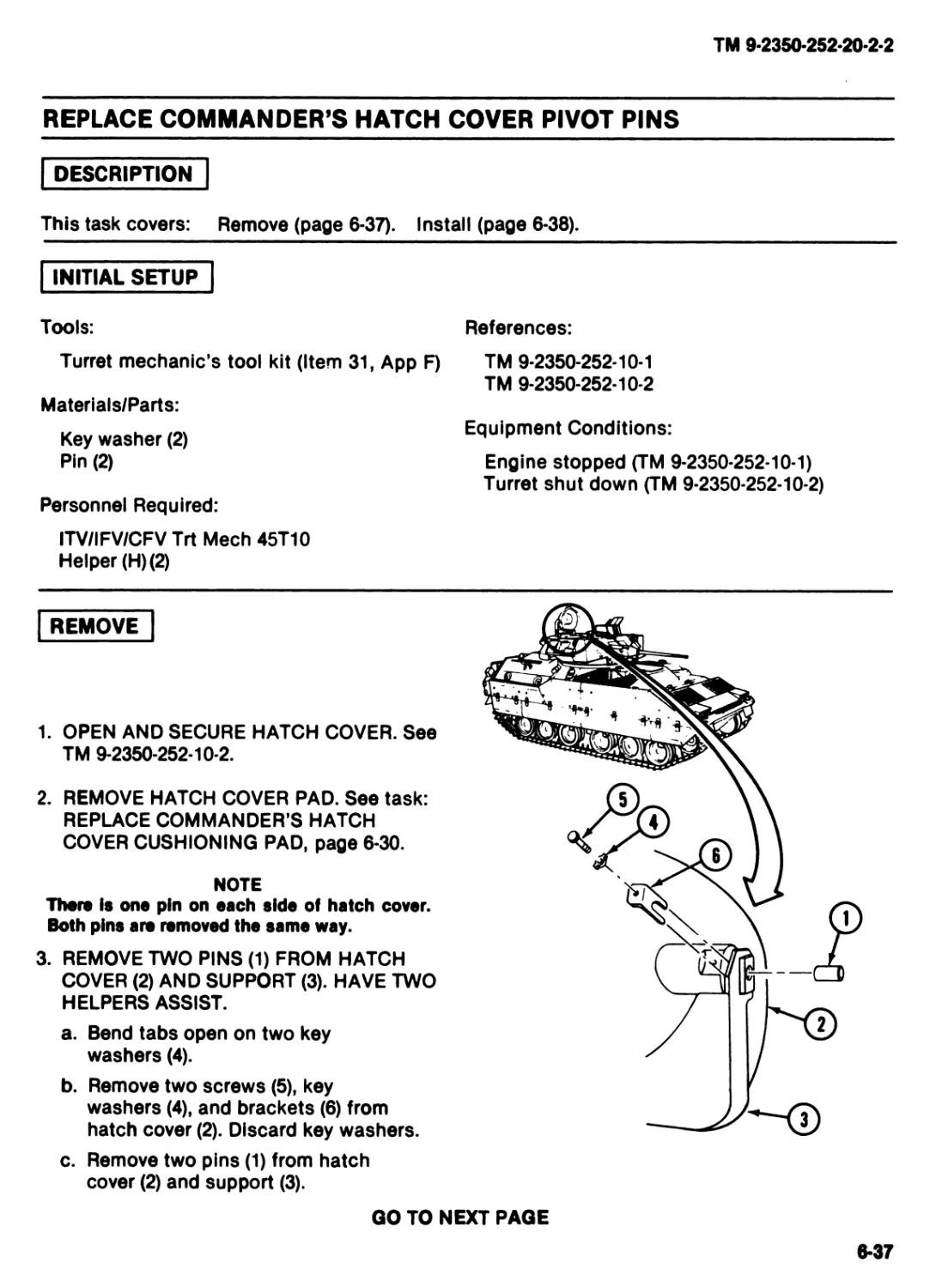

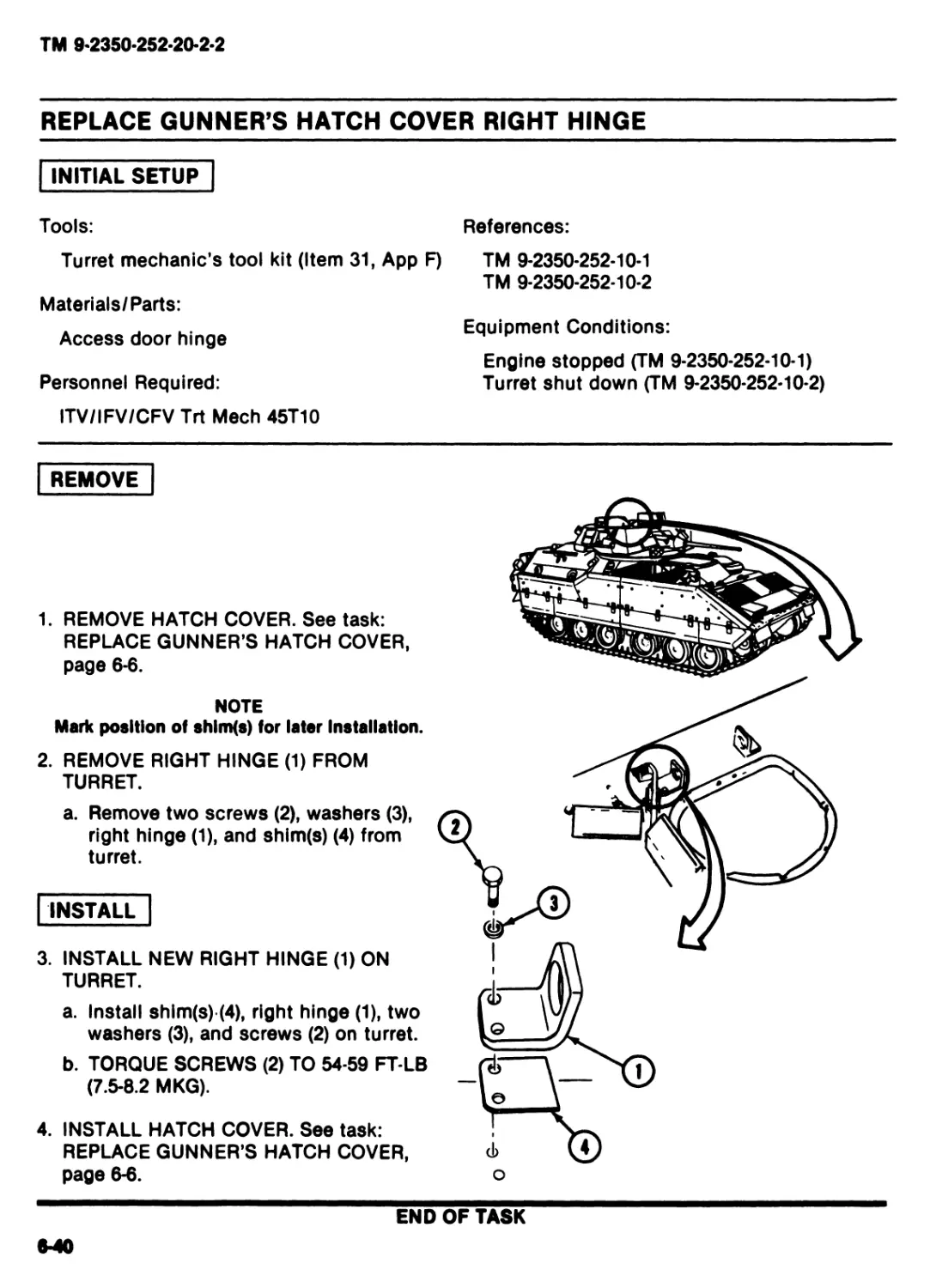


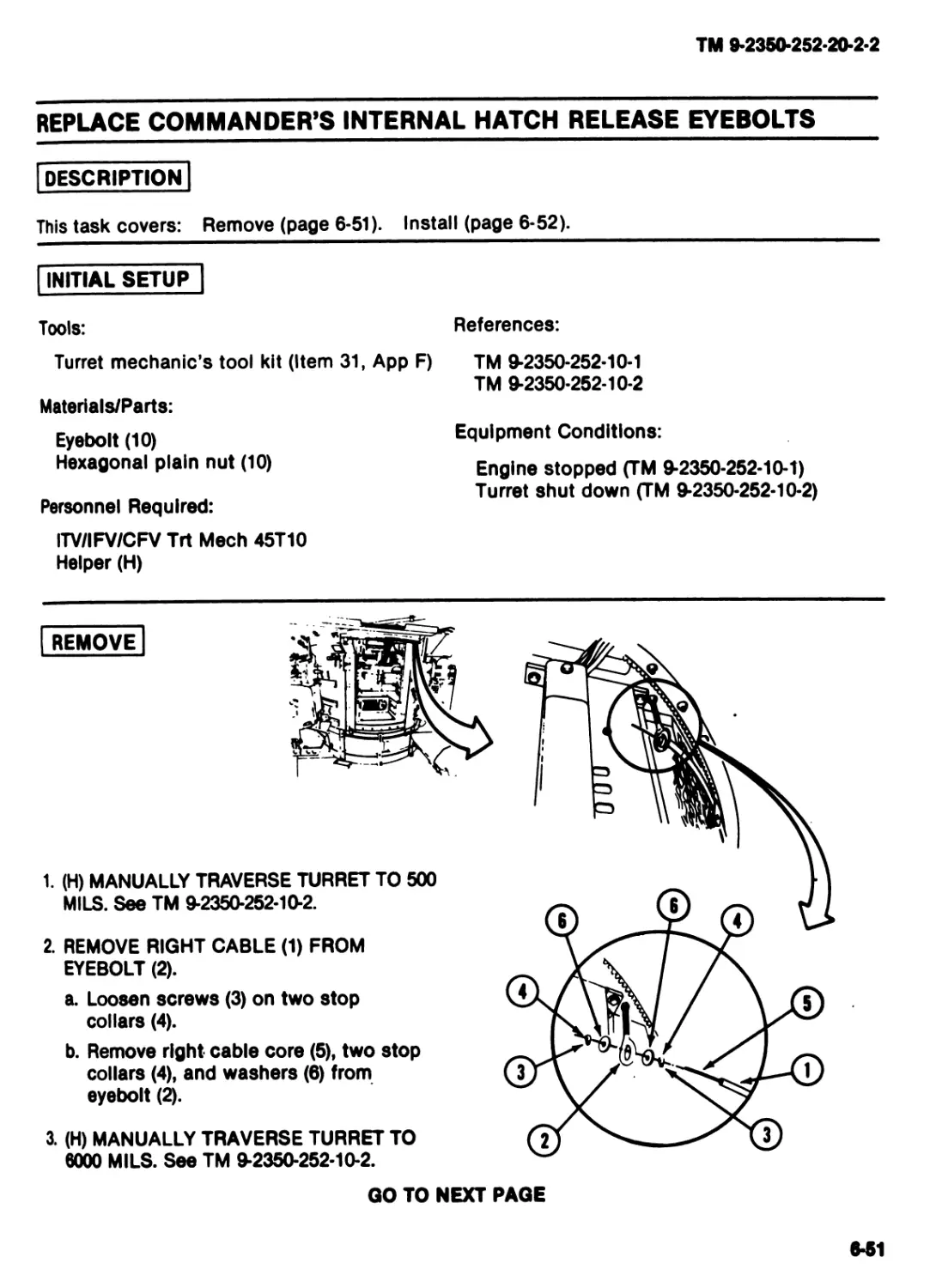


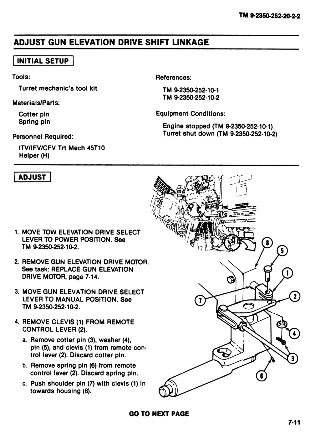
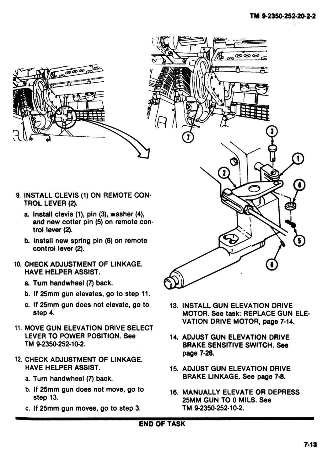
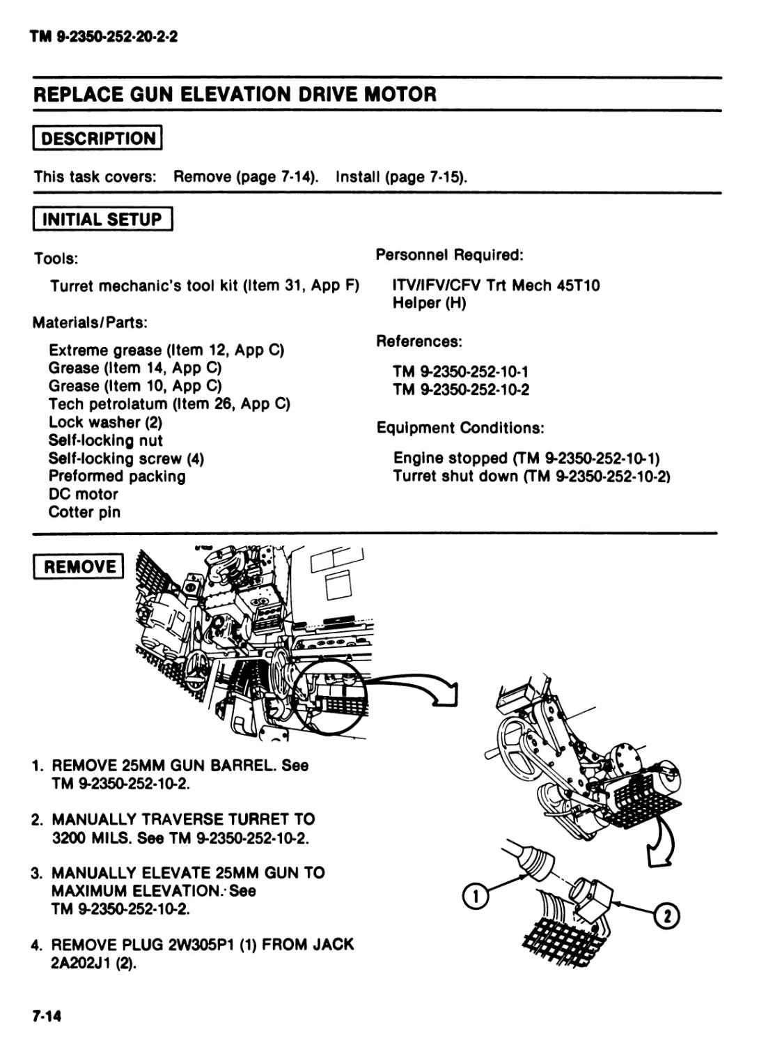
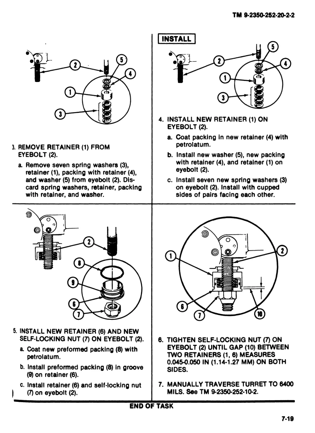
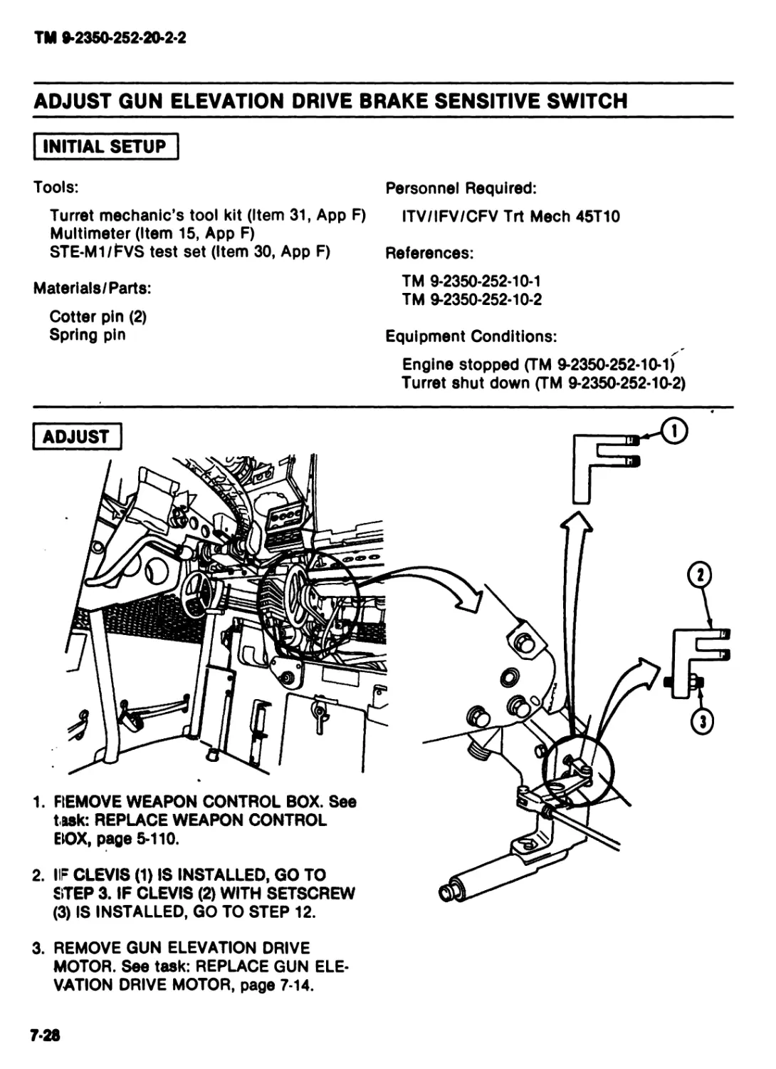
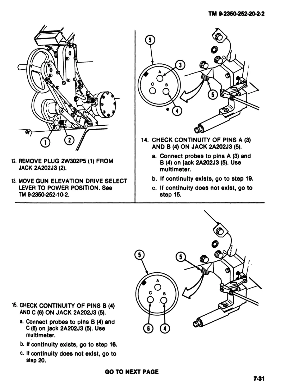
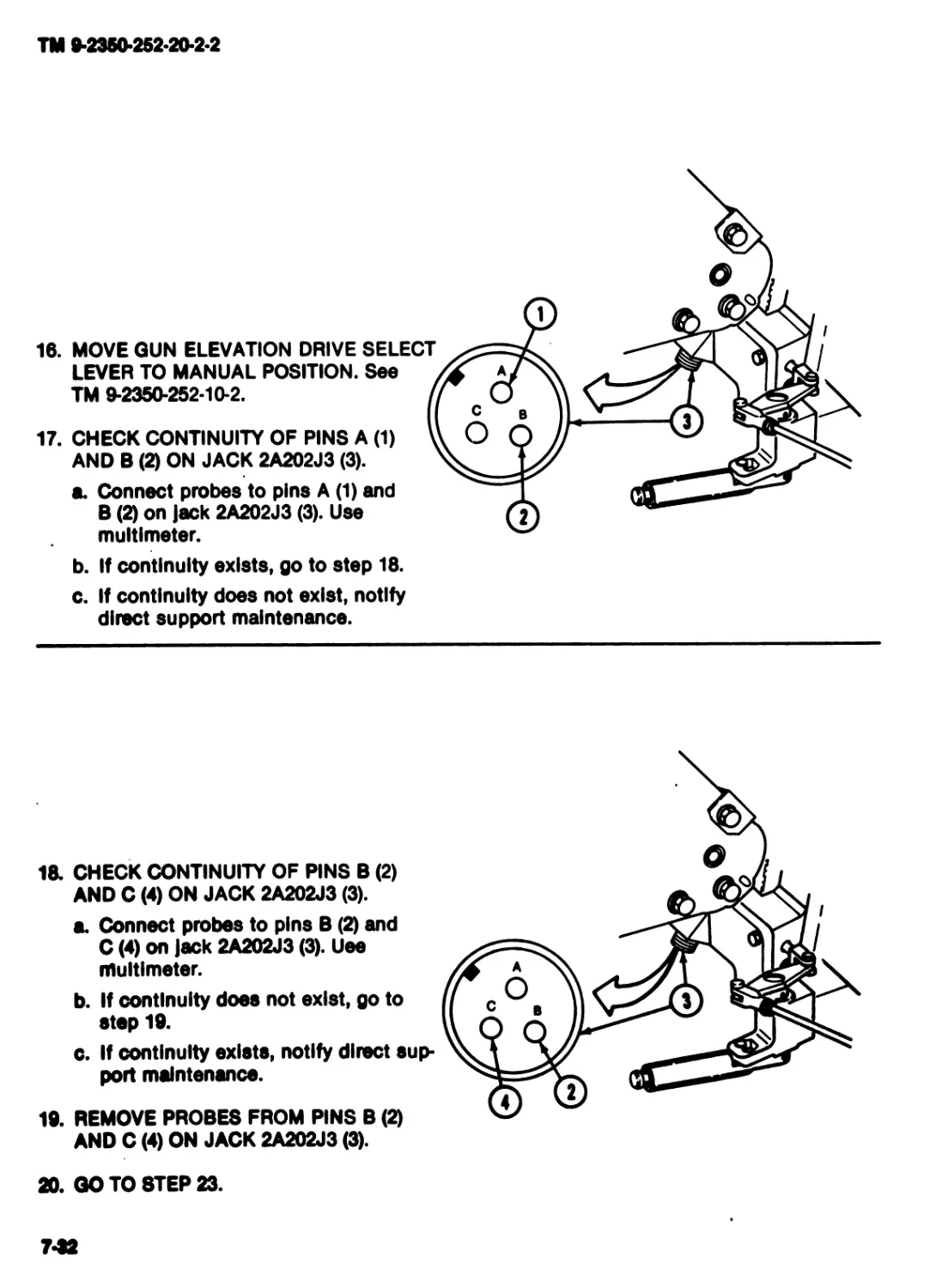
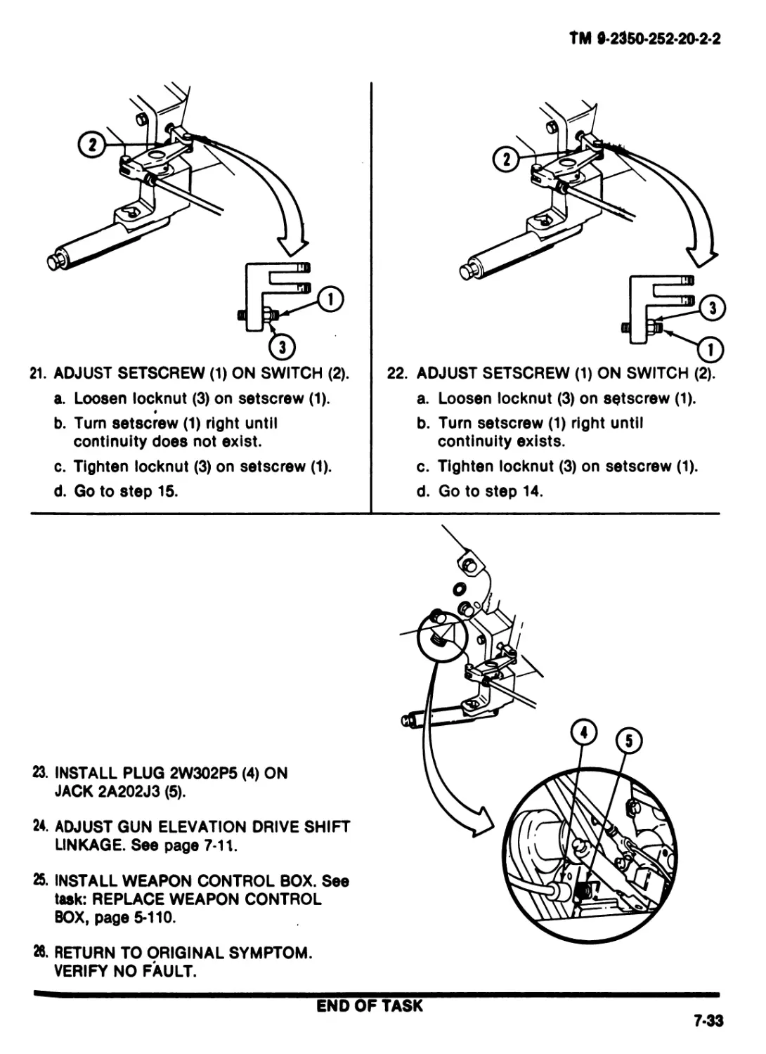
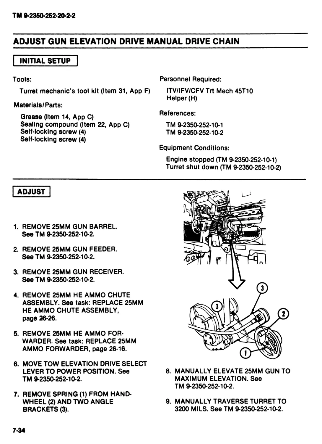

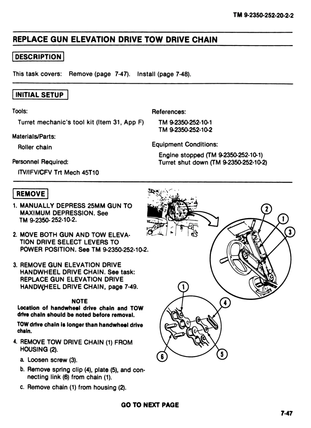
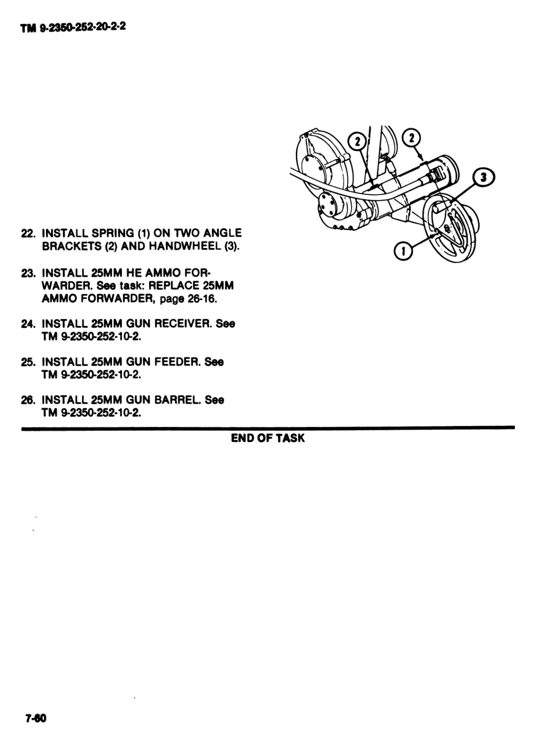
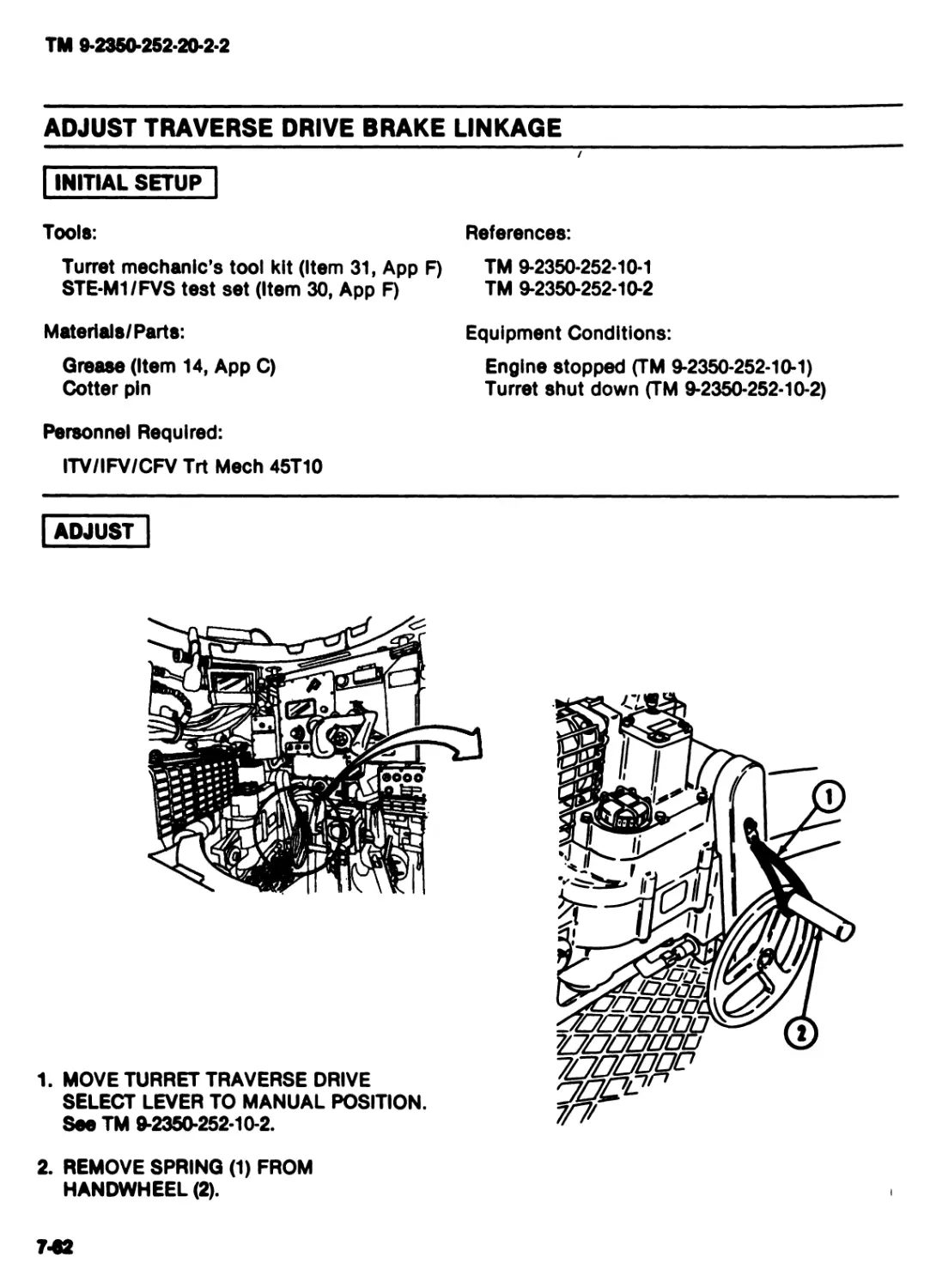
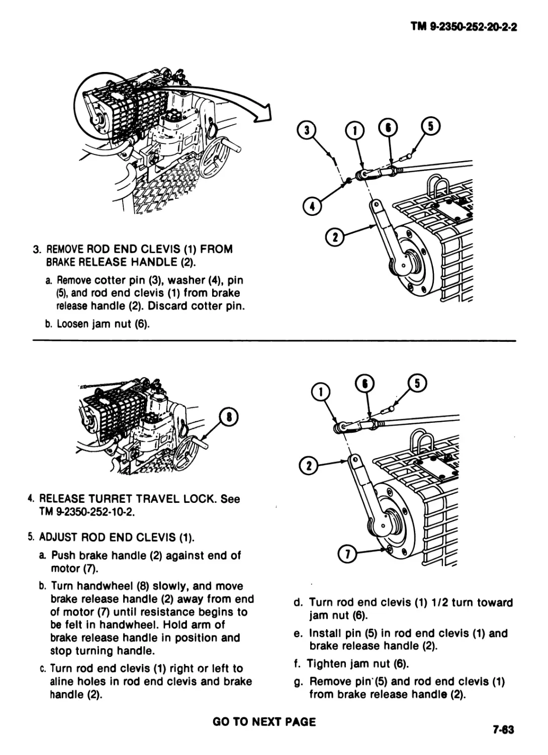
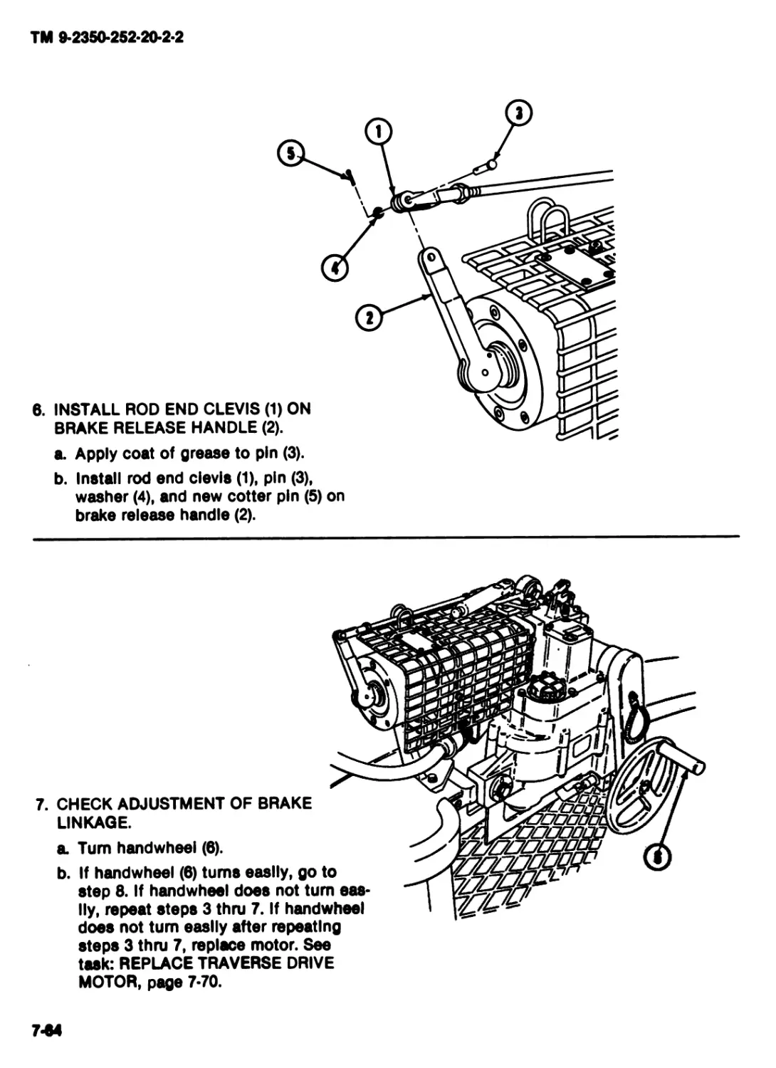
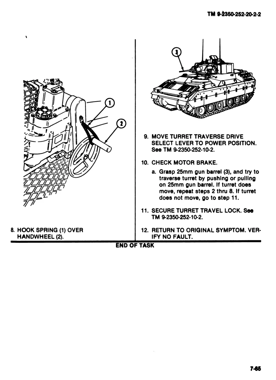
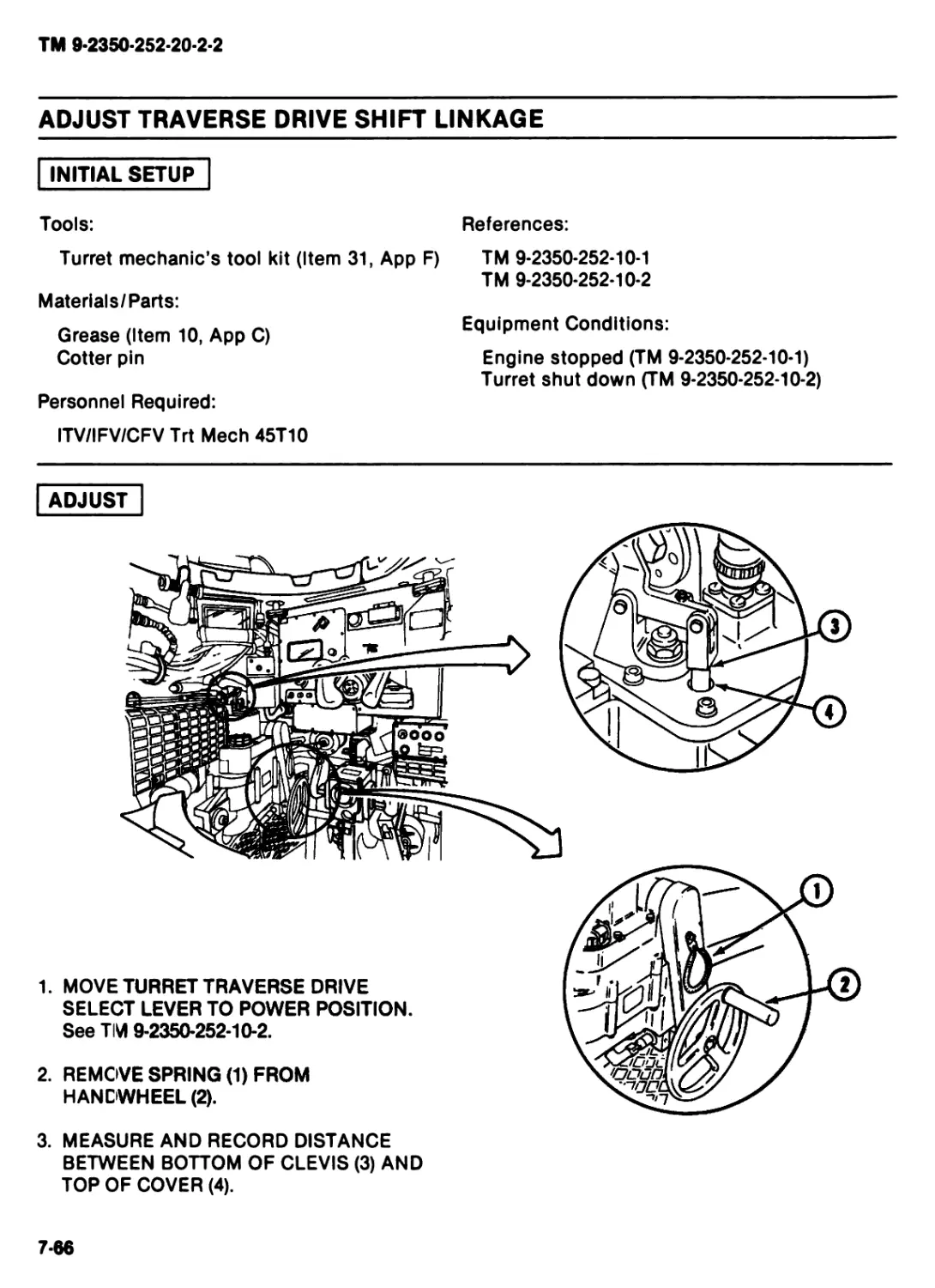

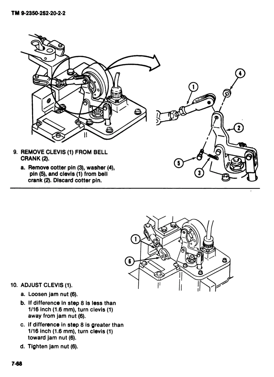
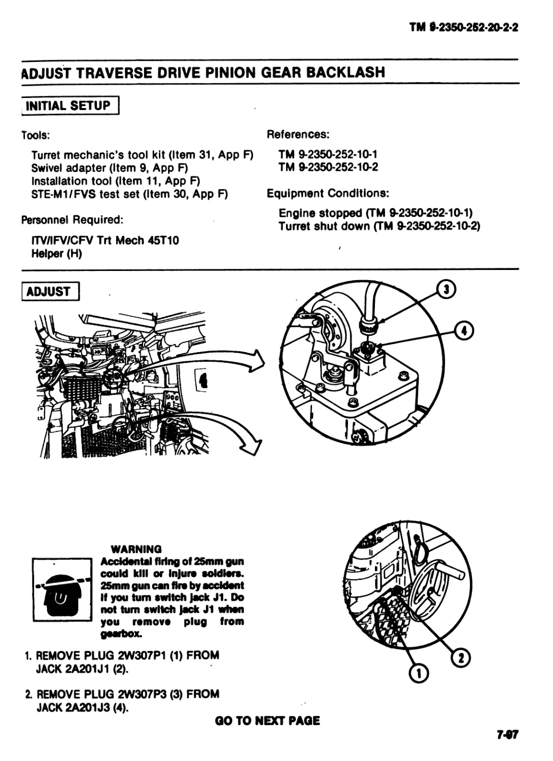
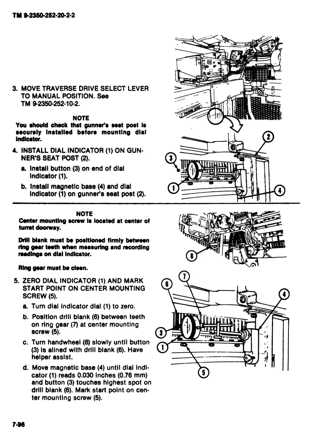
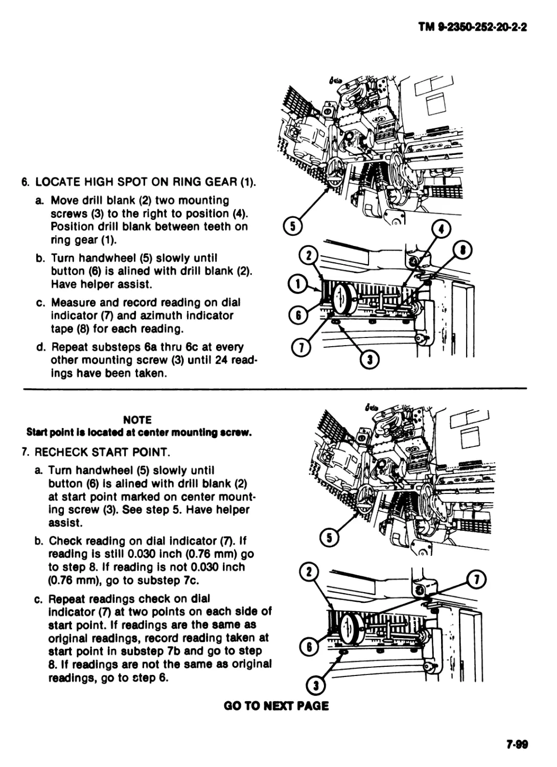
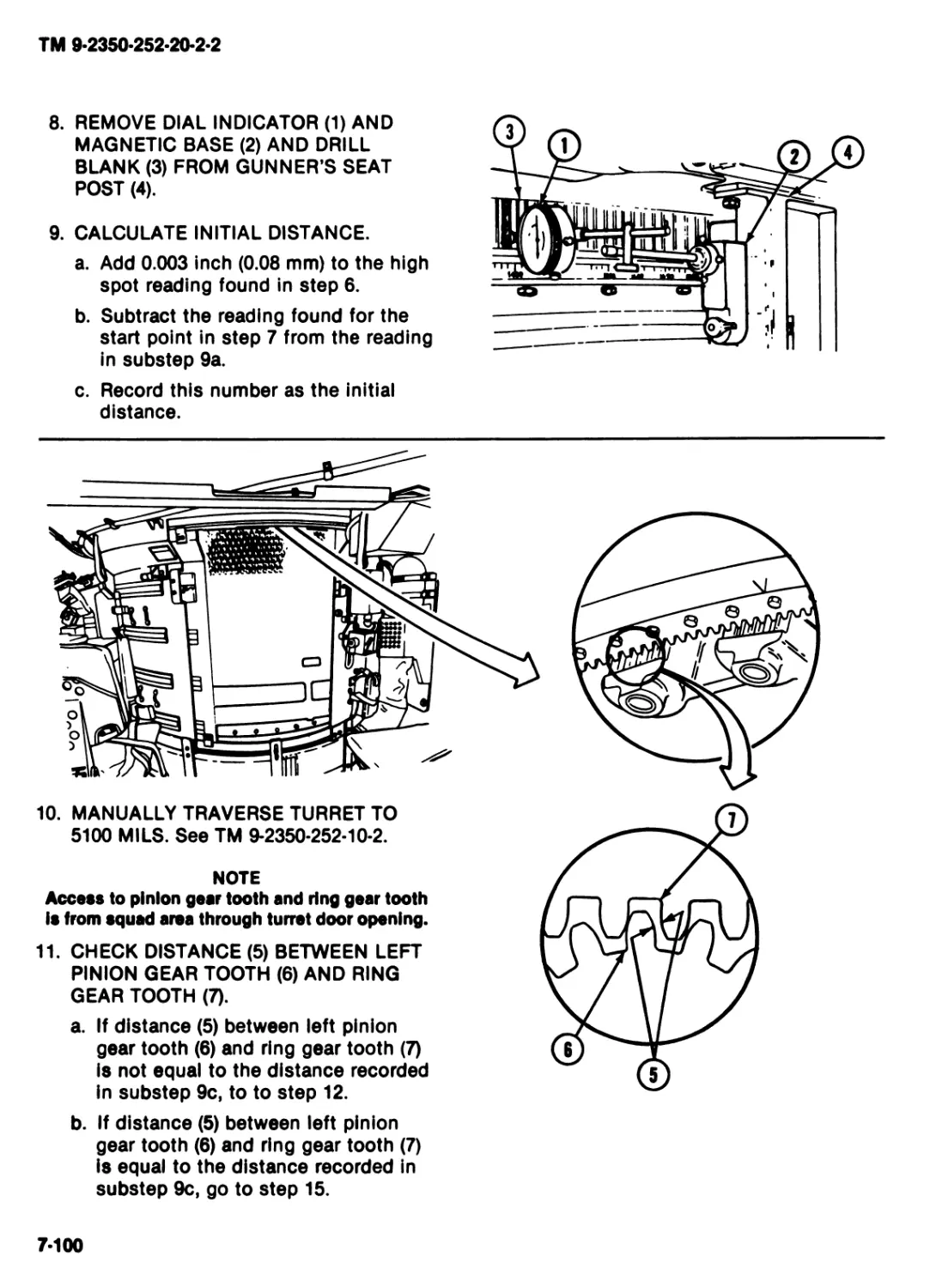
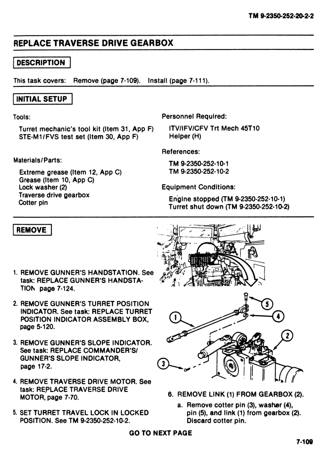
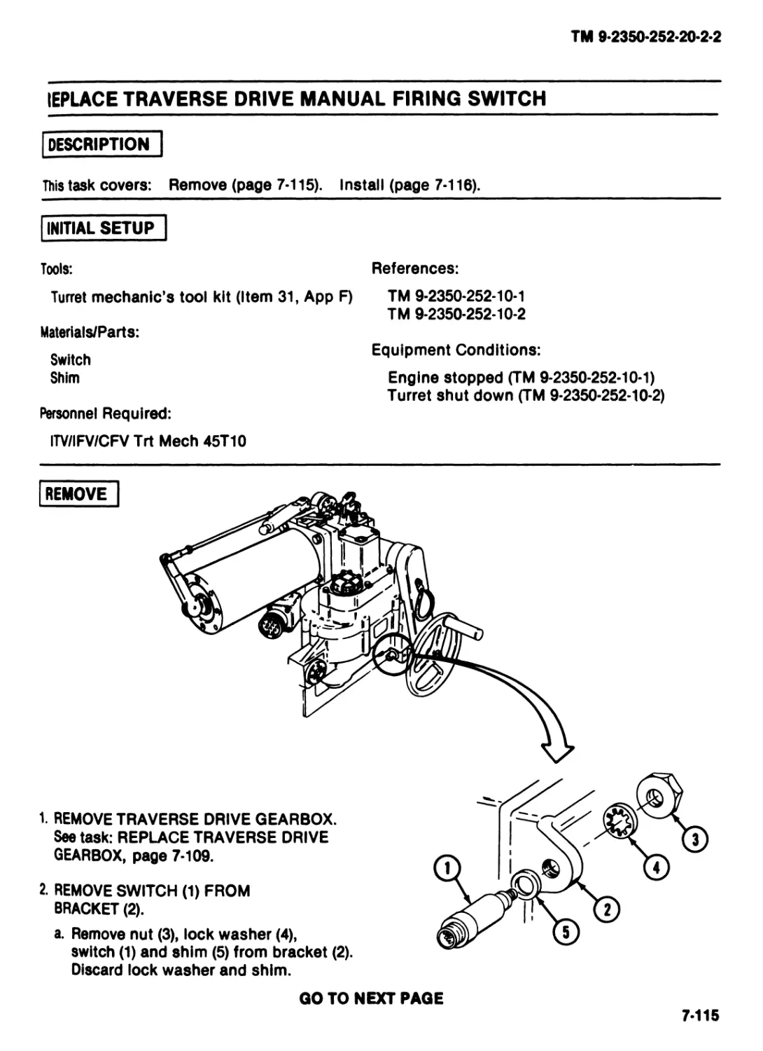
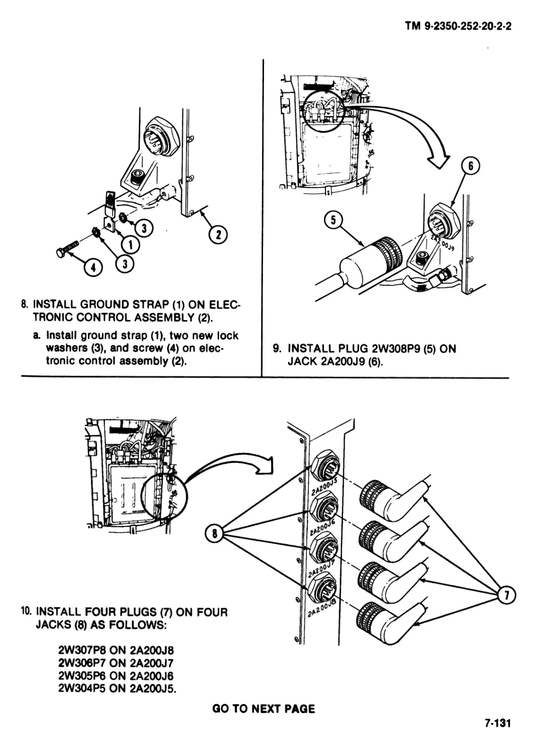
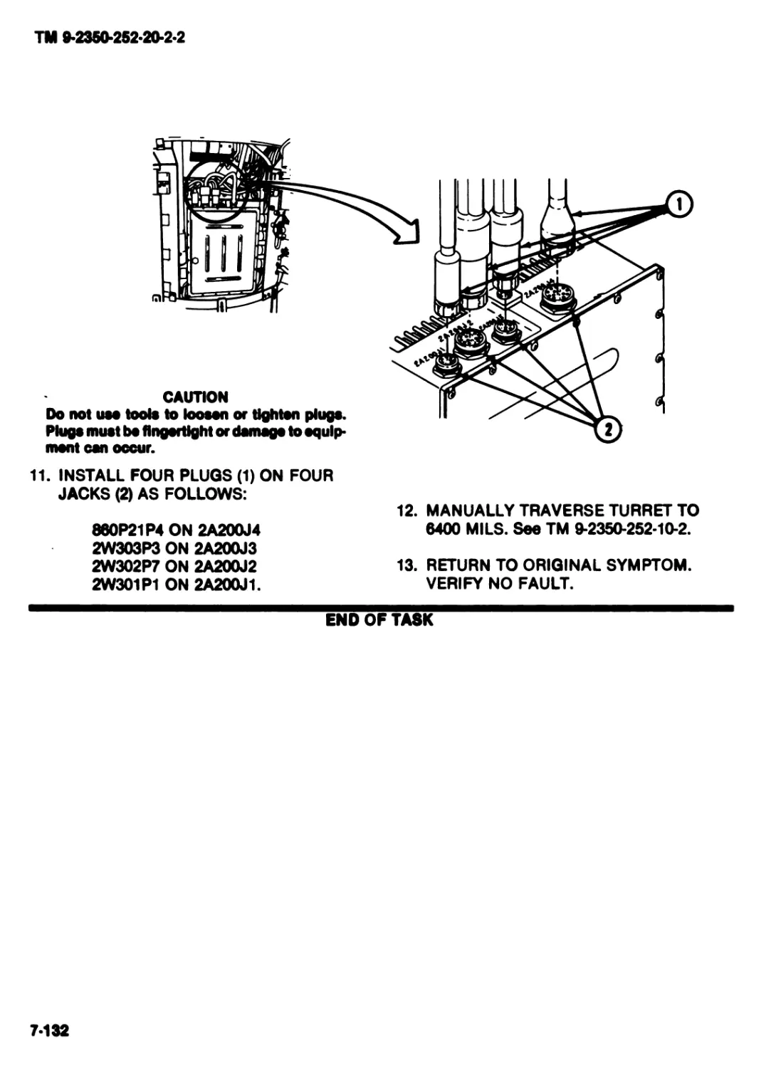
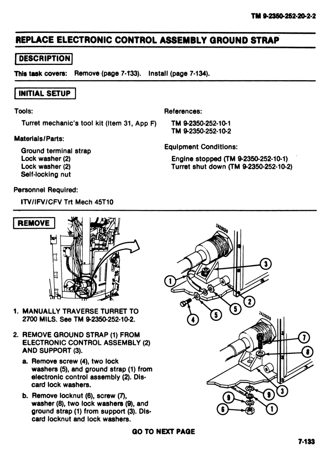
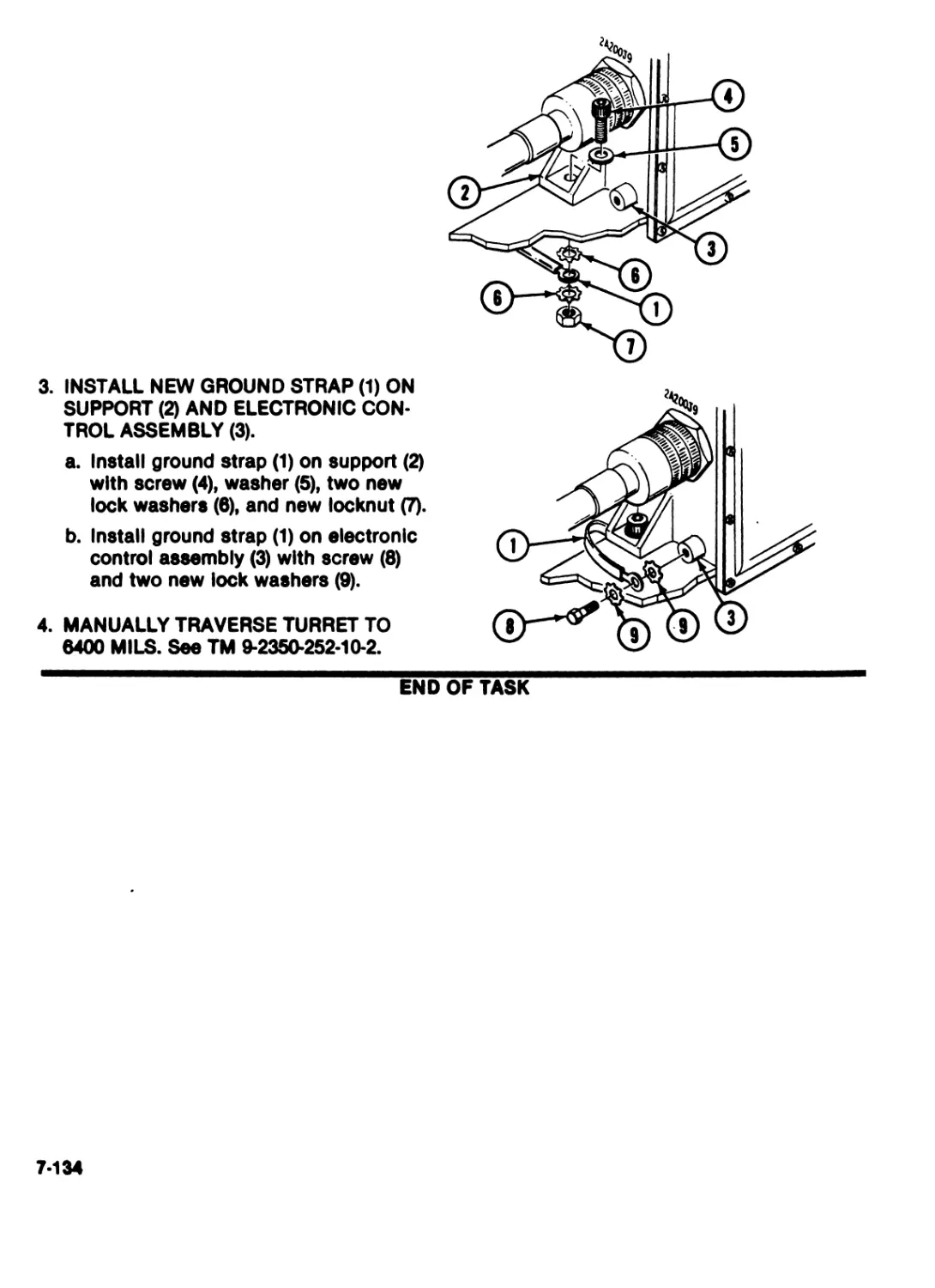


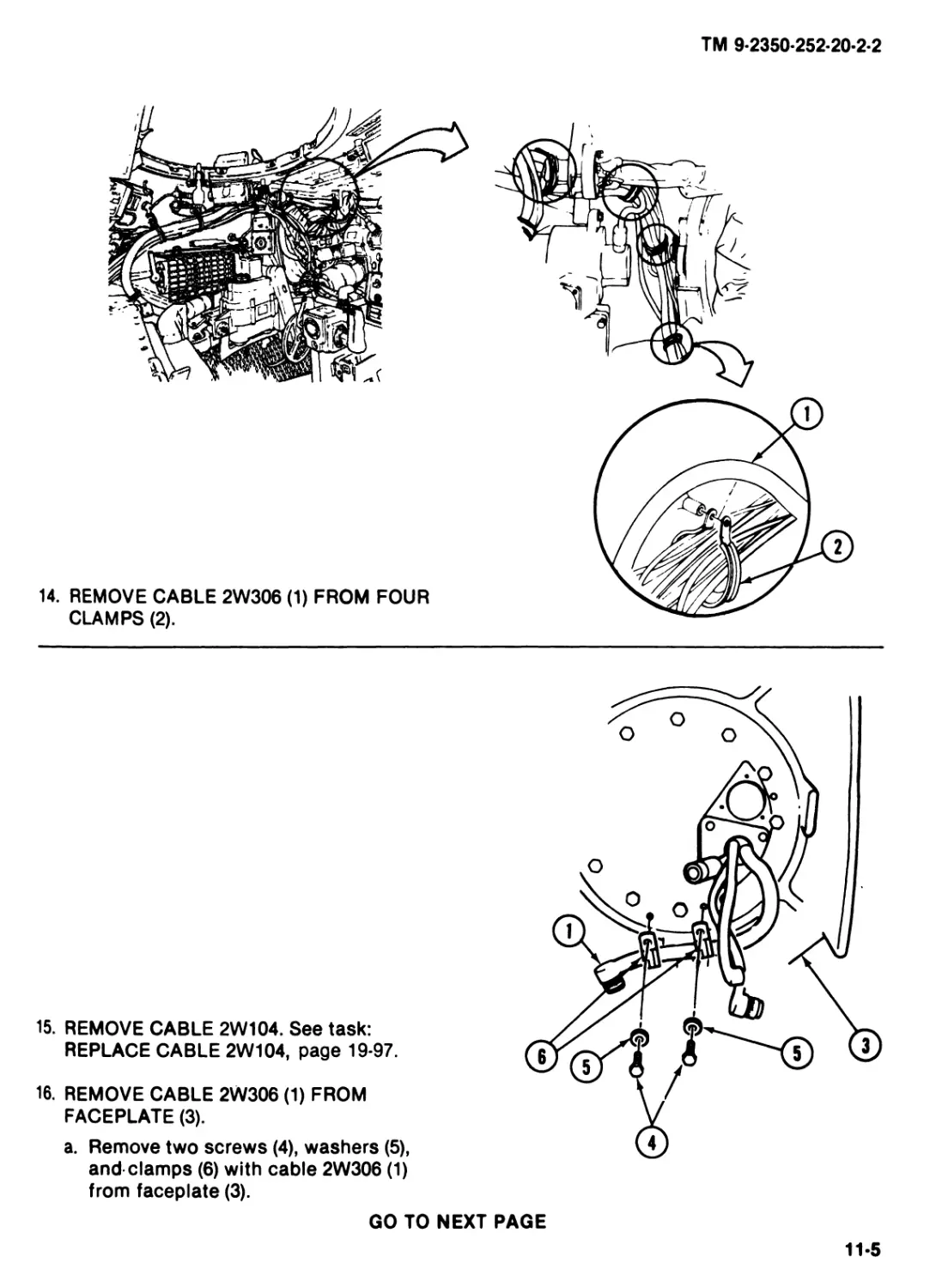
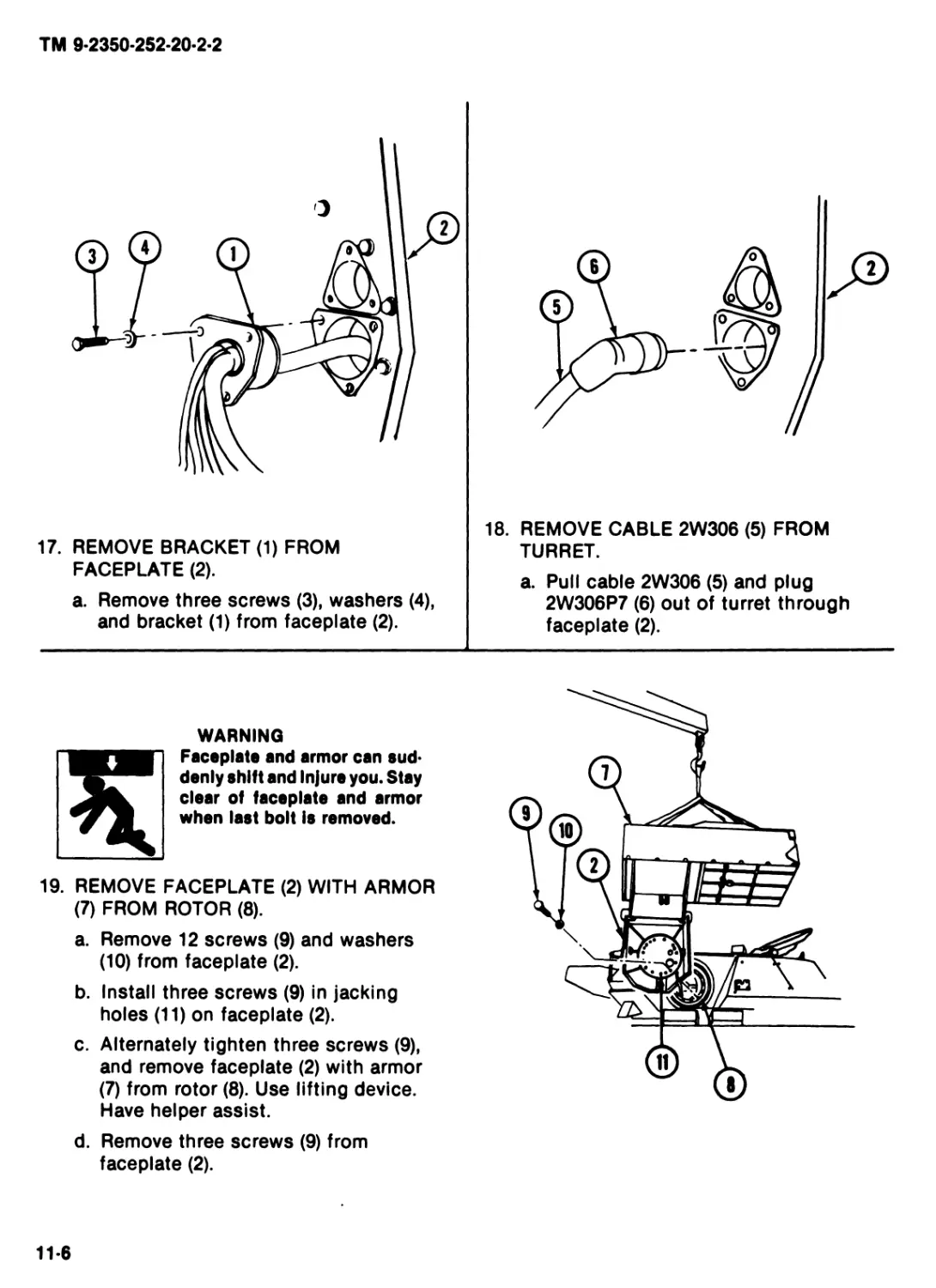
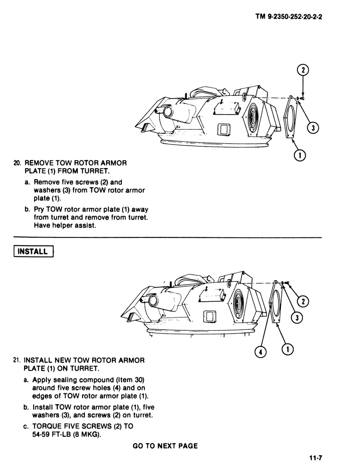
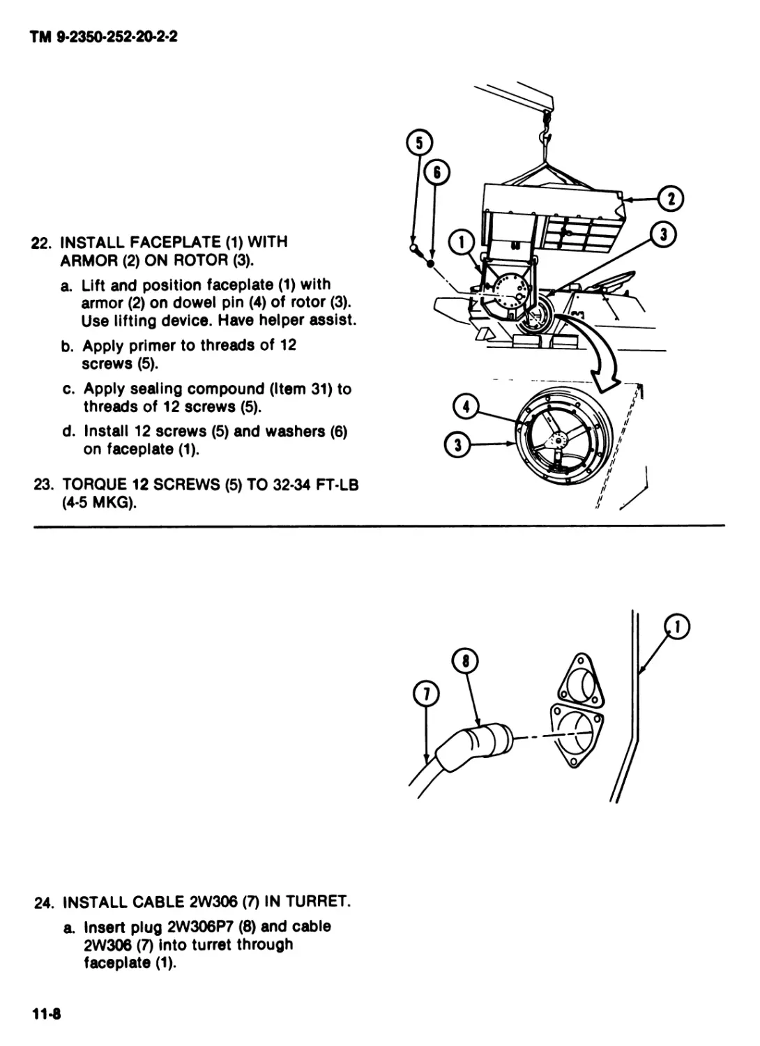
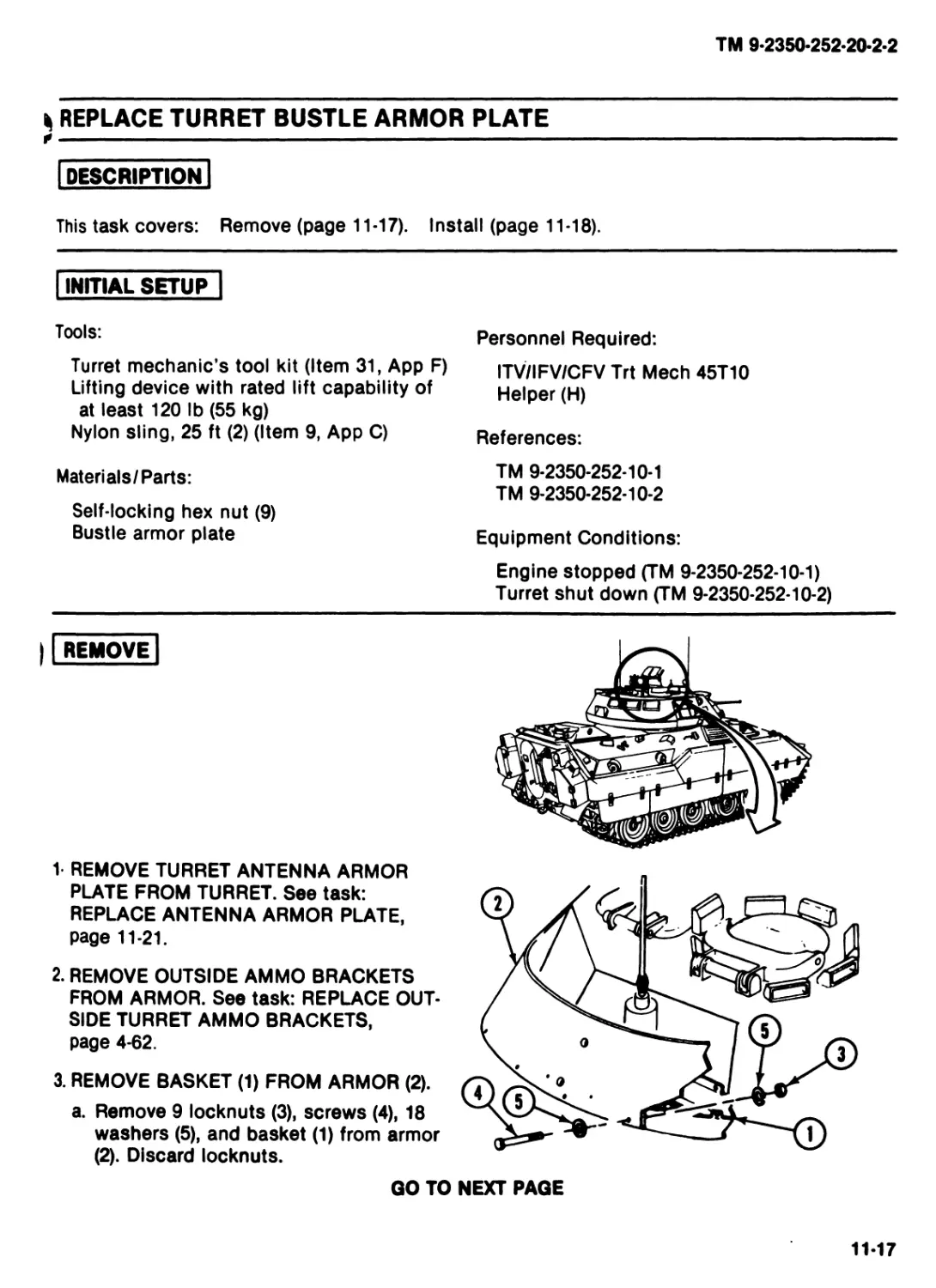


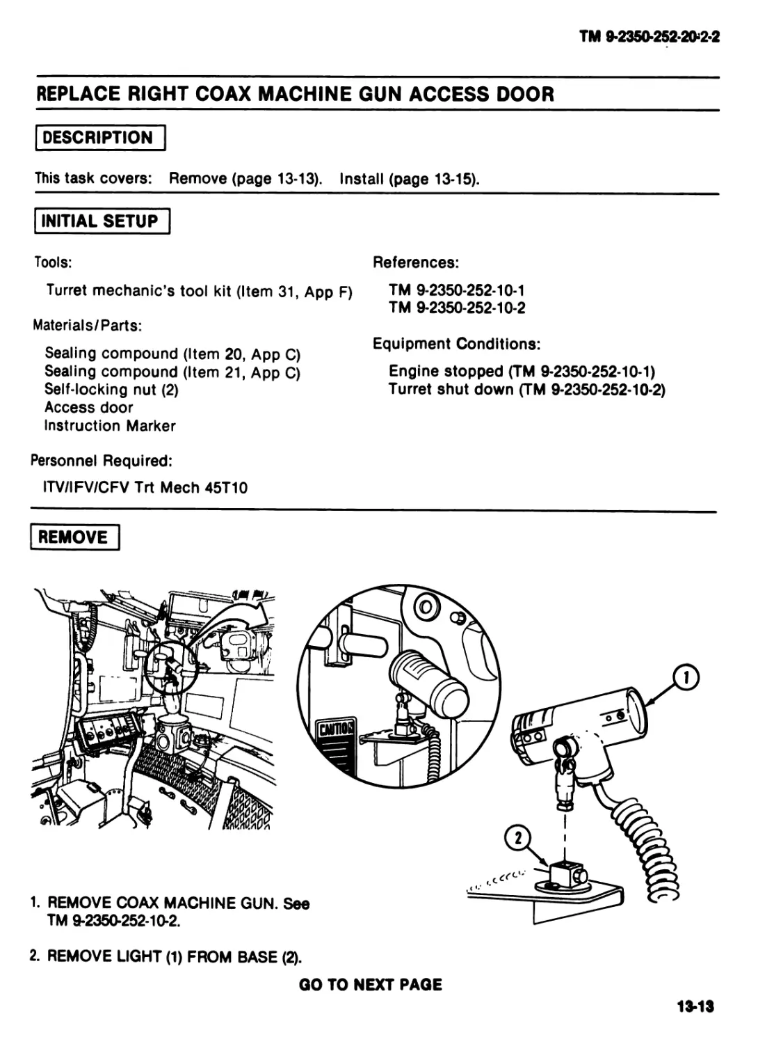
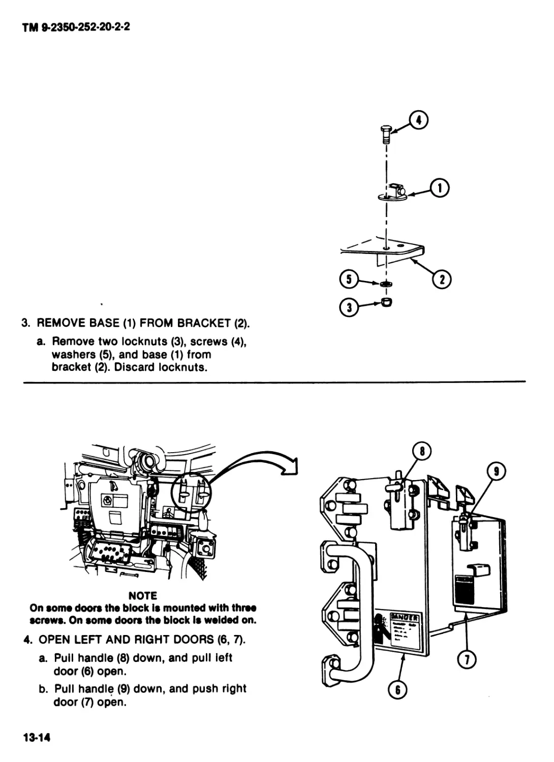
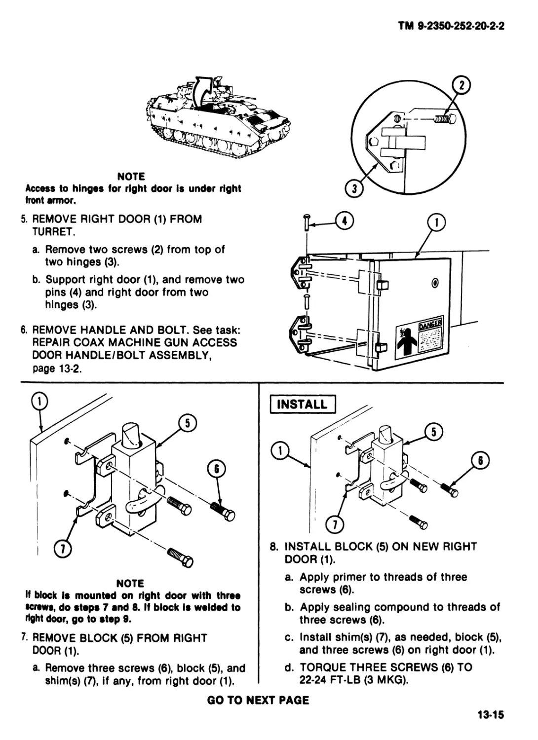
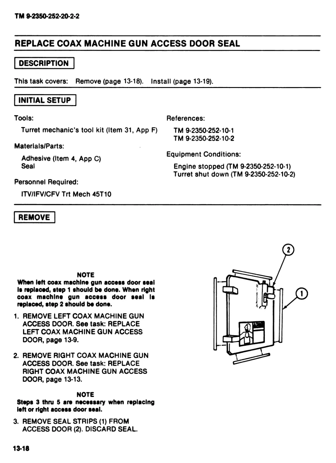
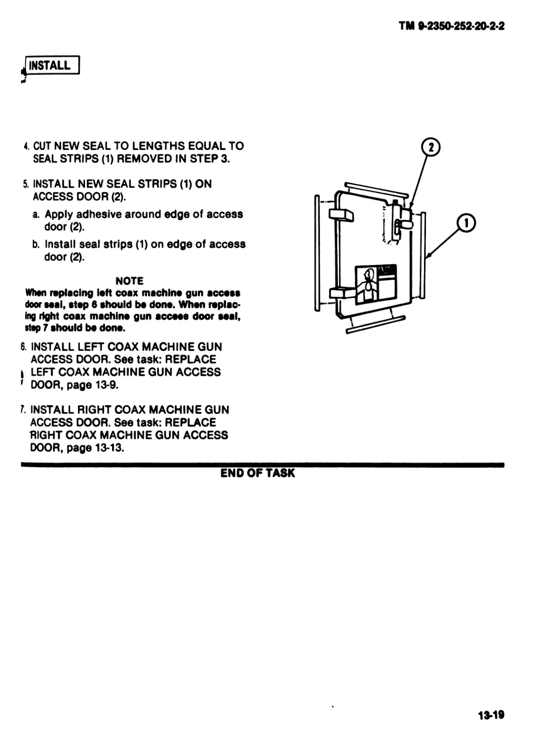


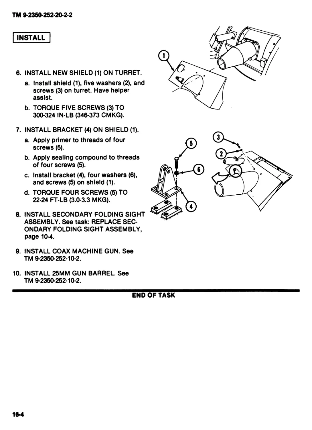
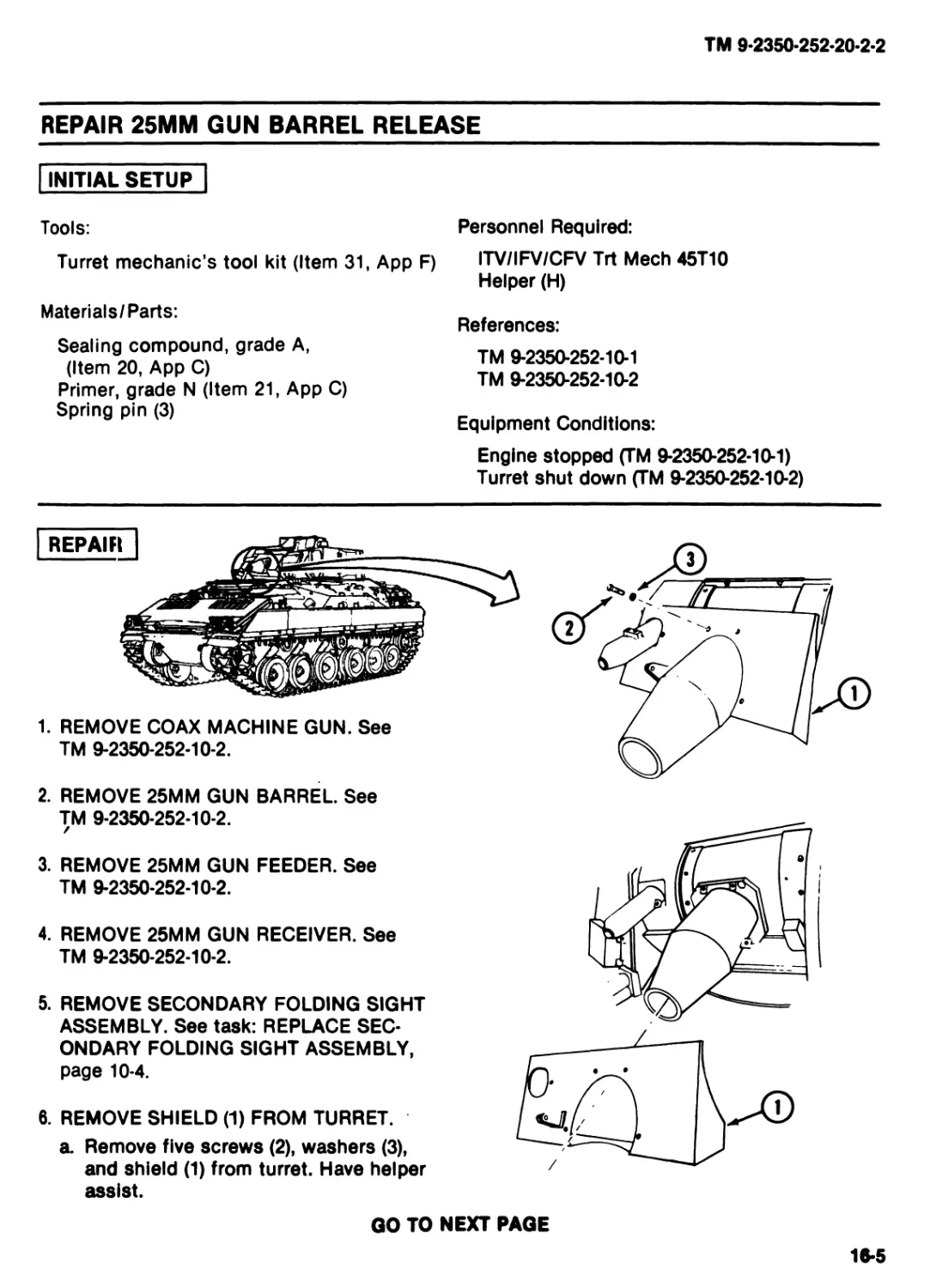
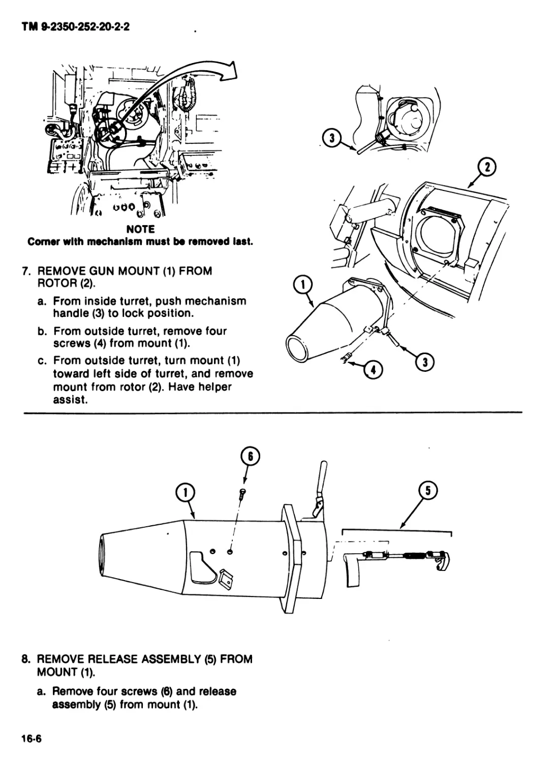

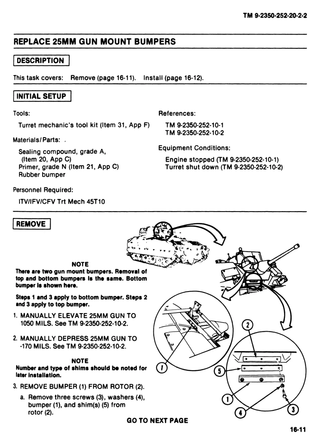
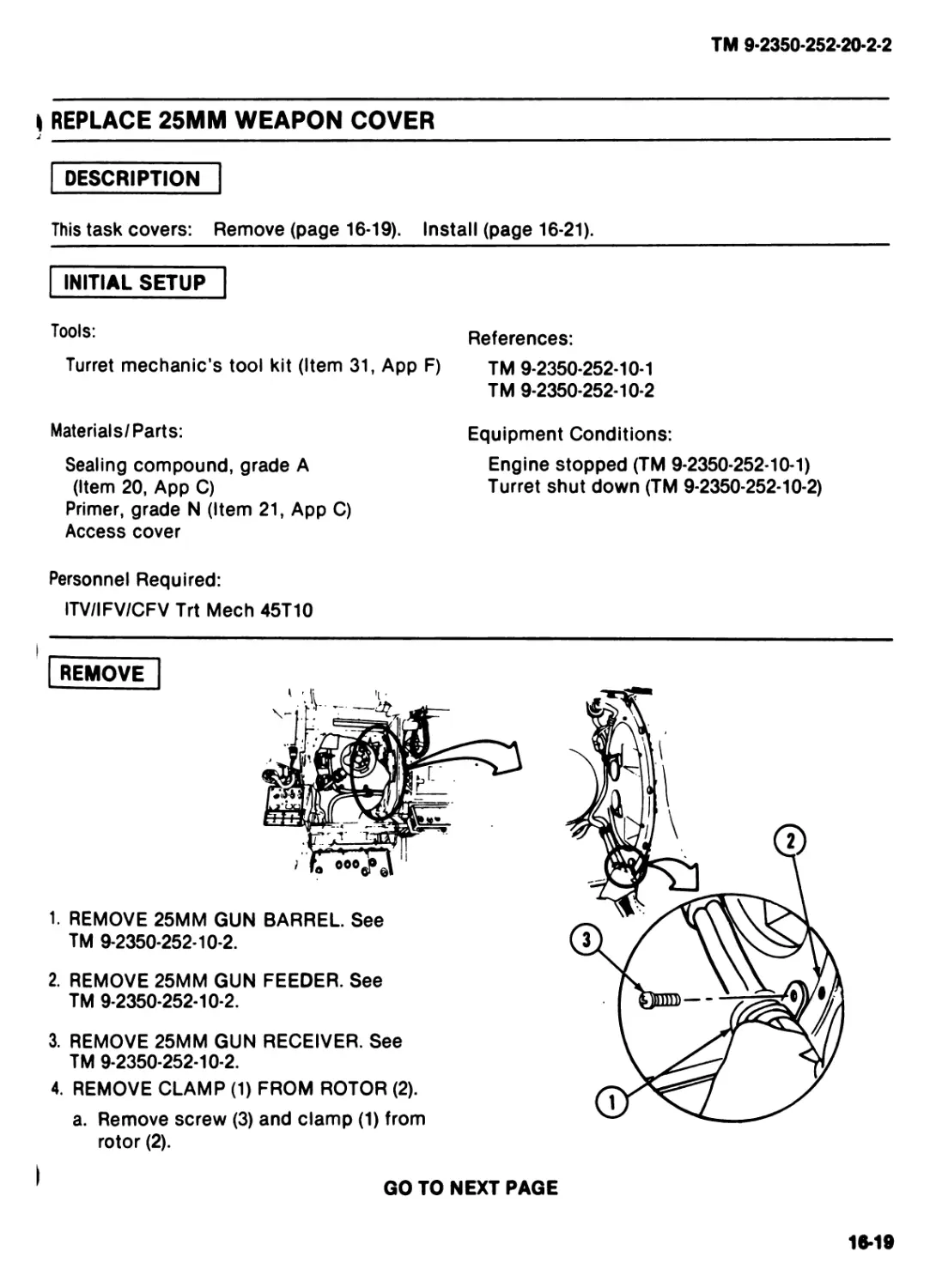

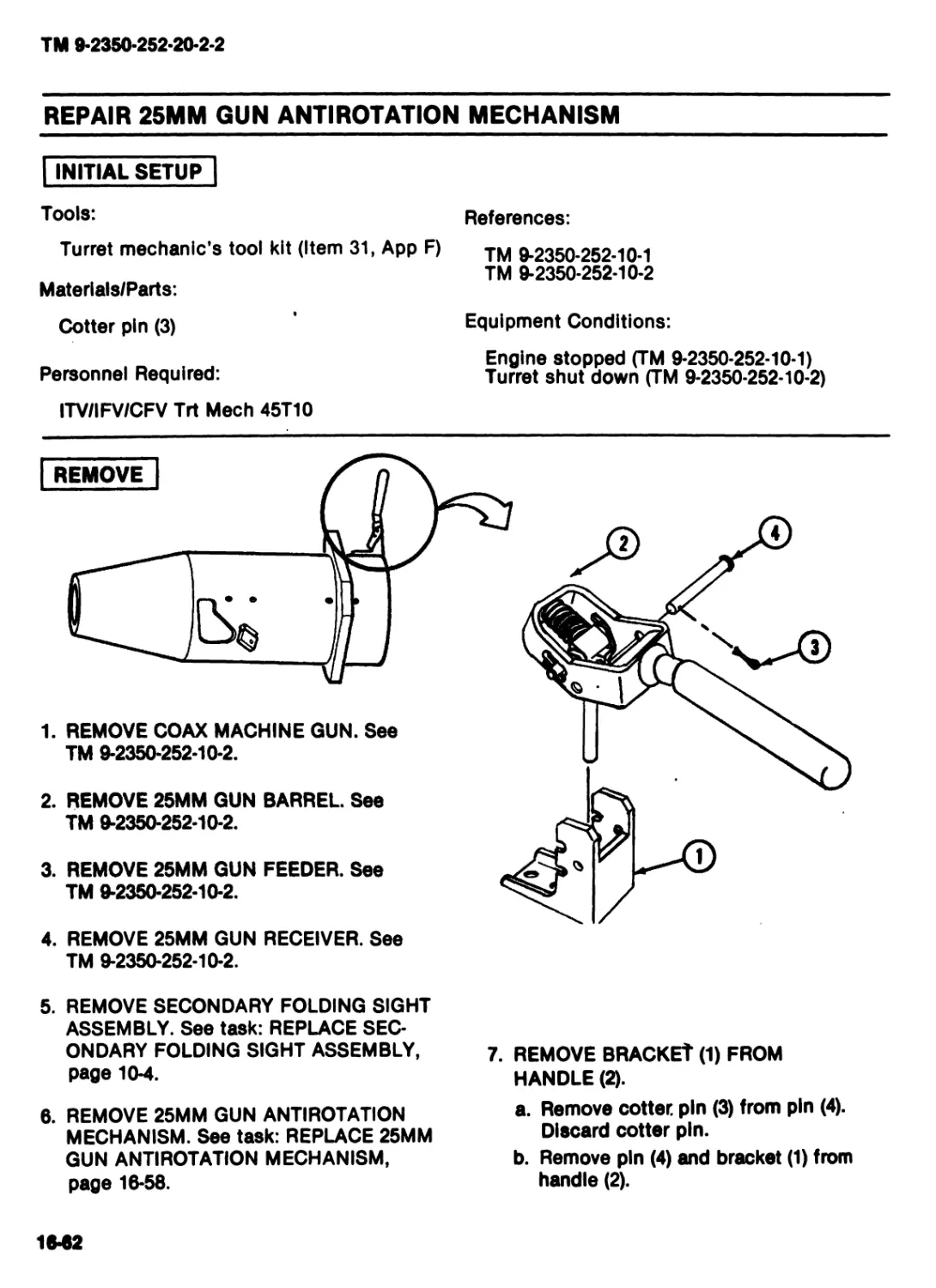
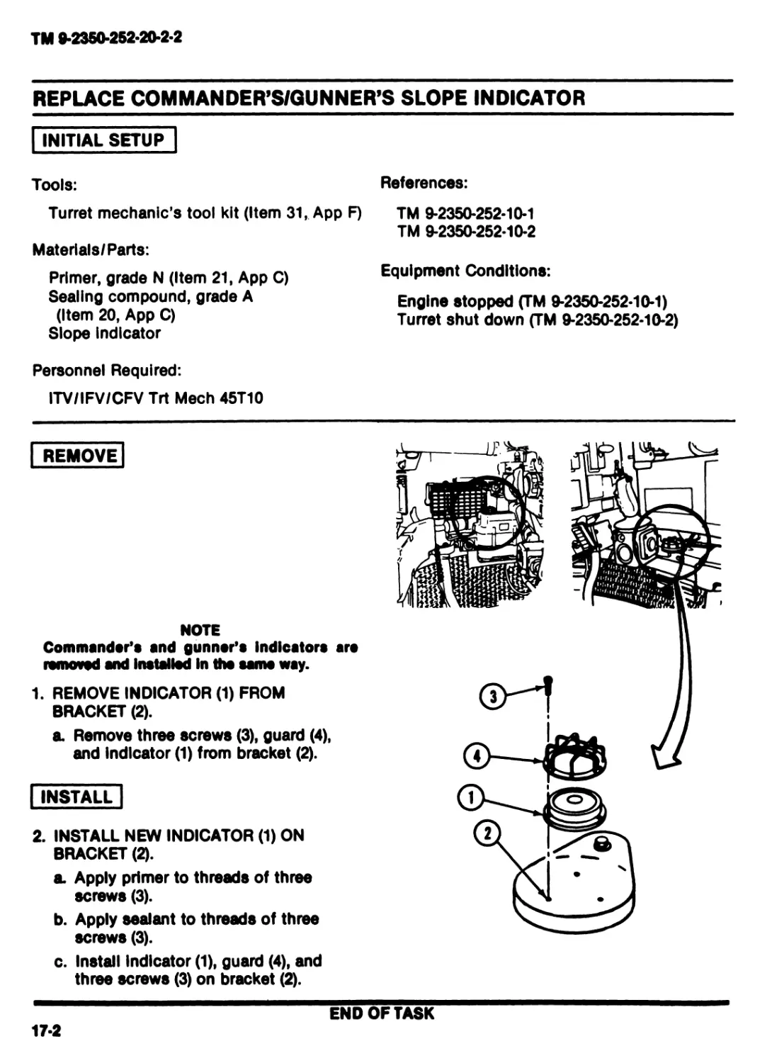


Похожие


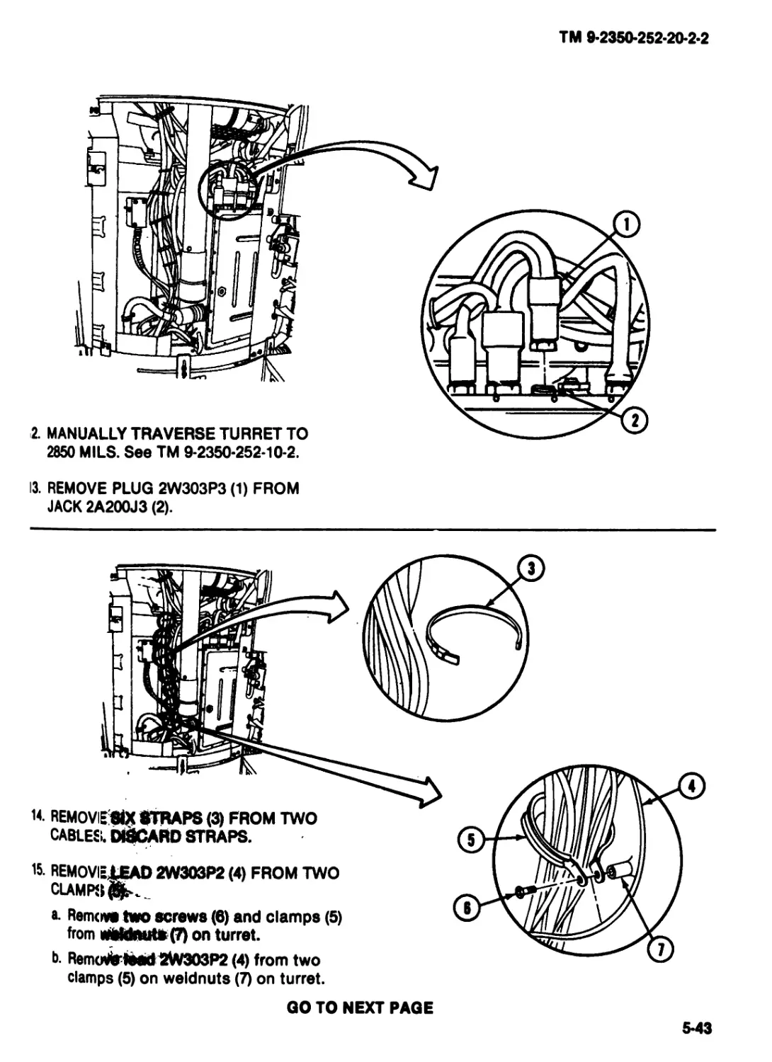
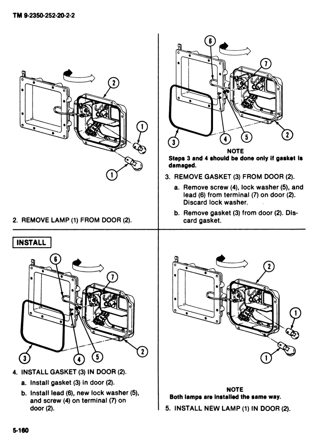
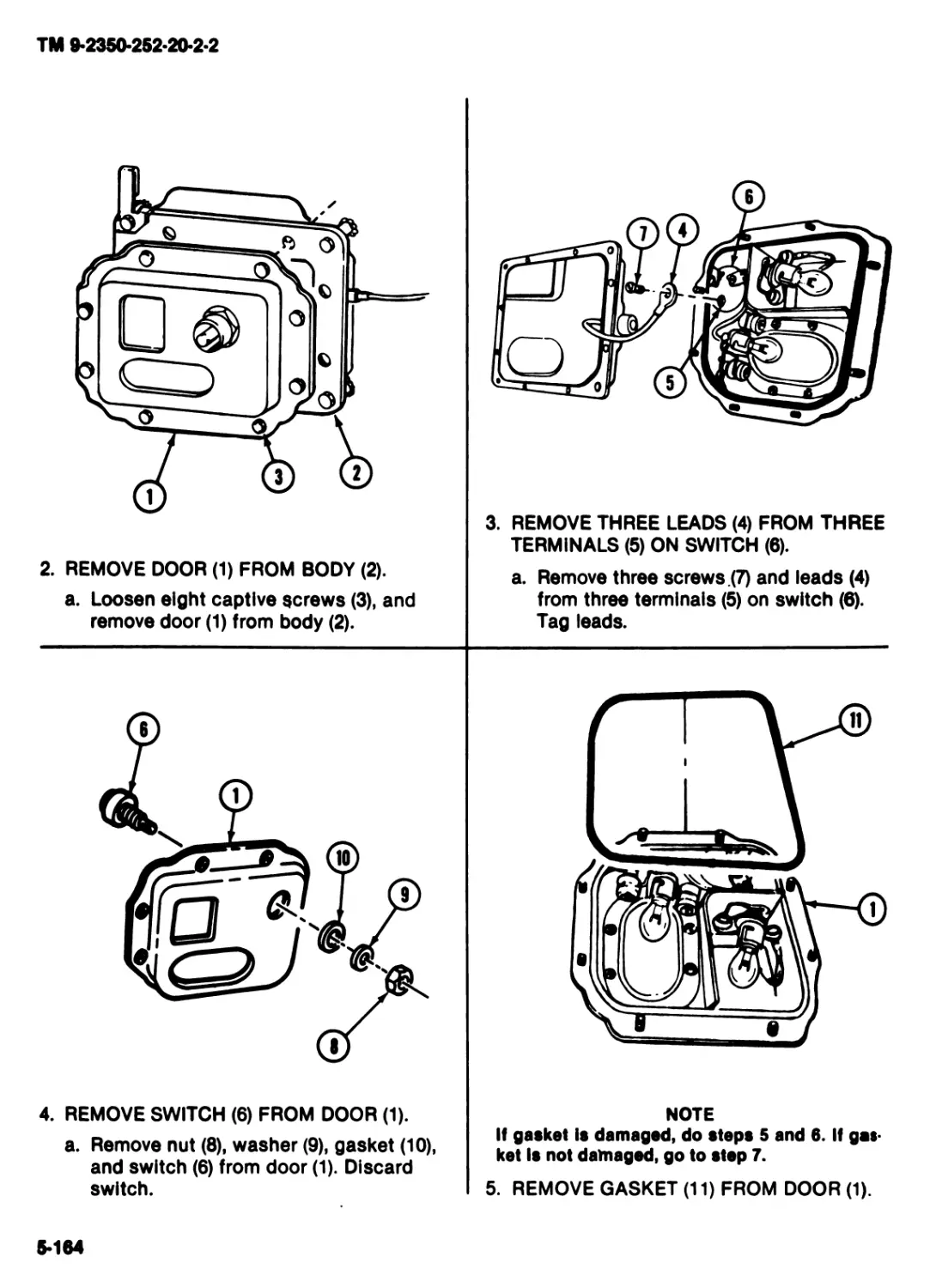
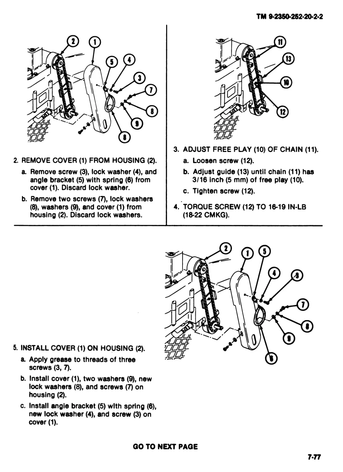
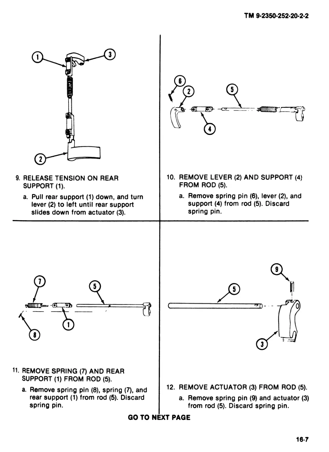
Текст
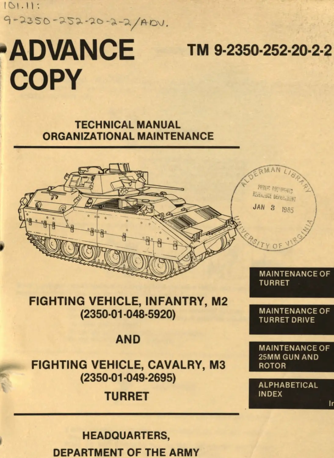
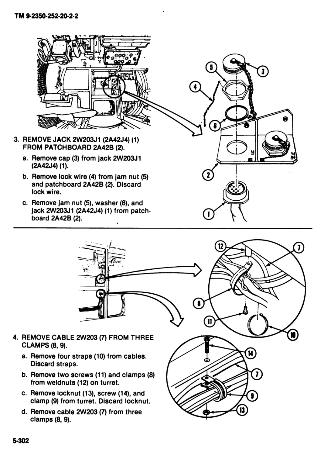
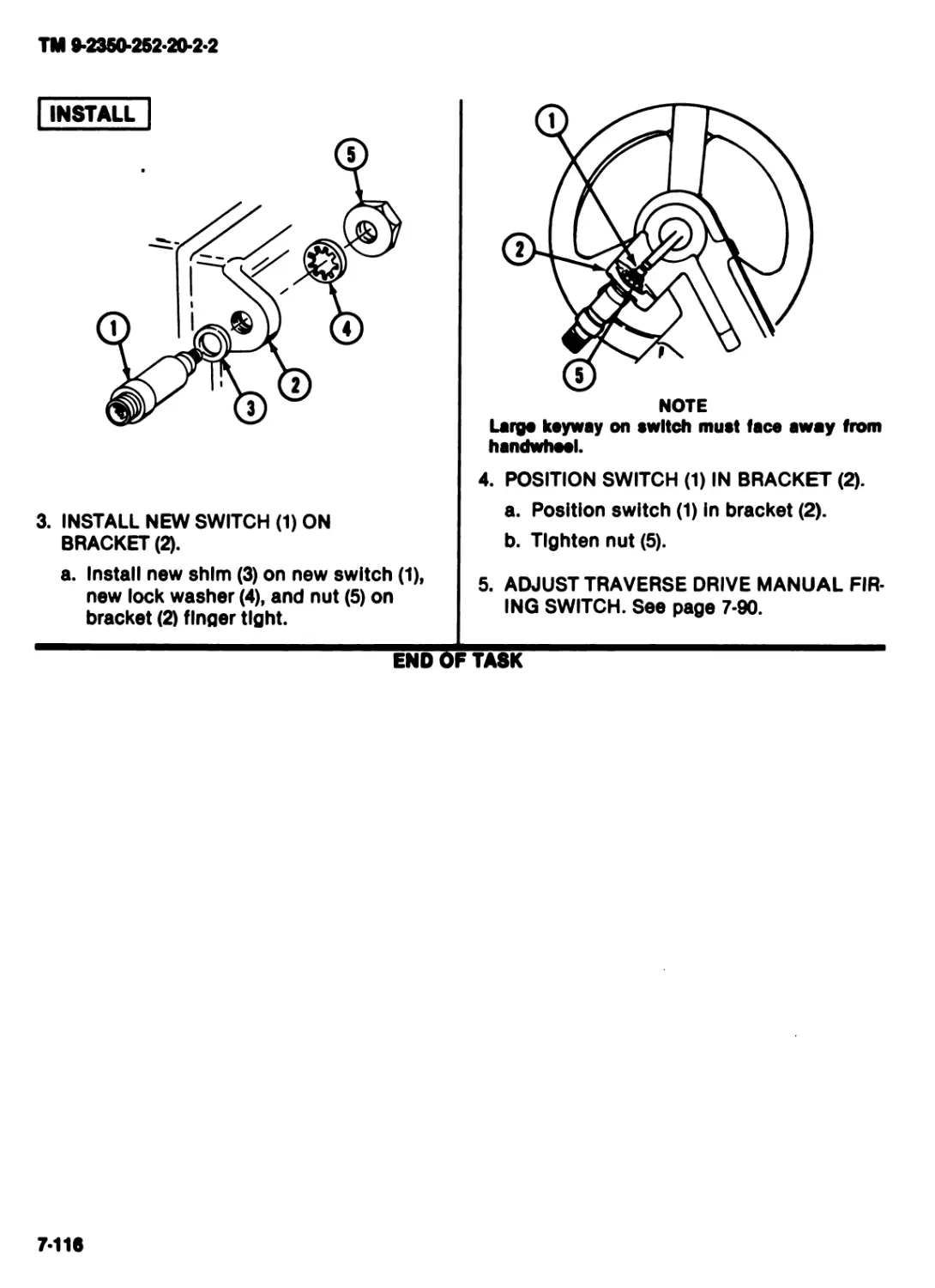
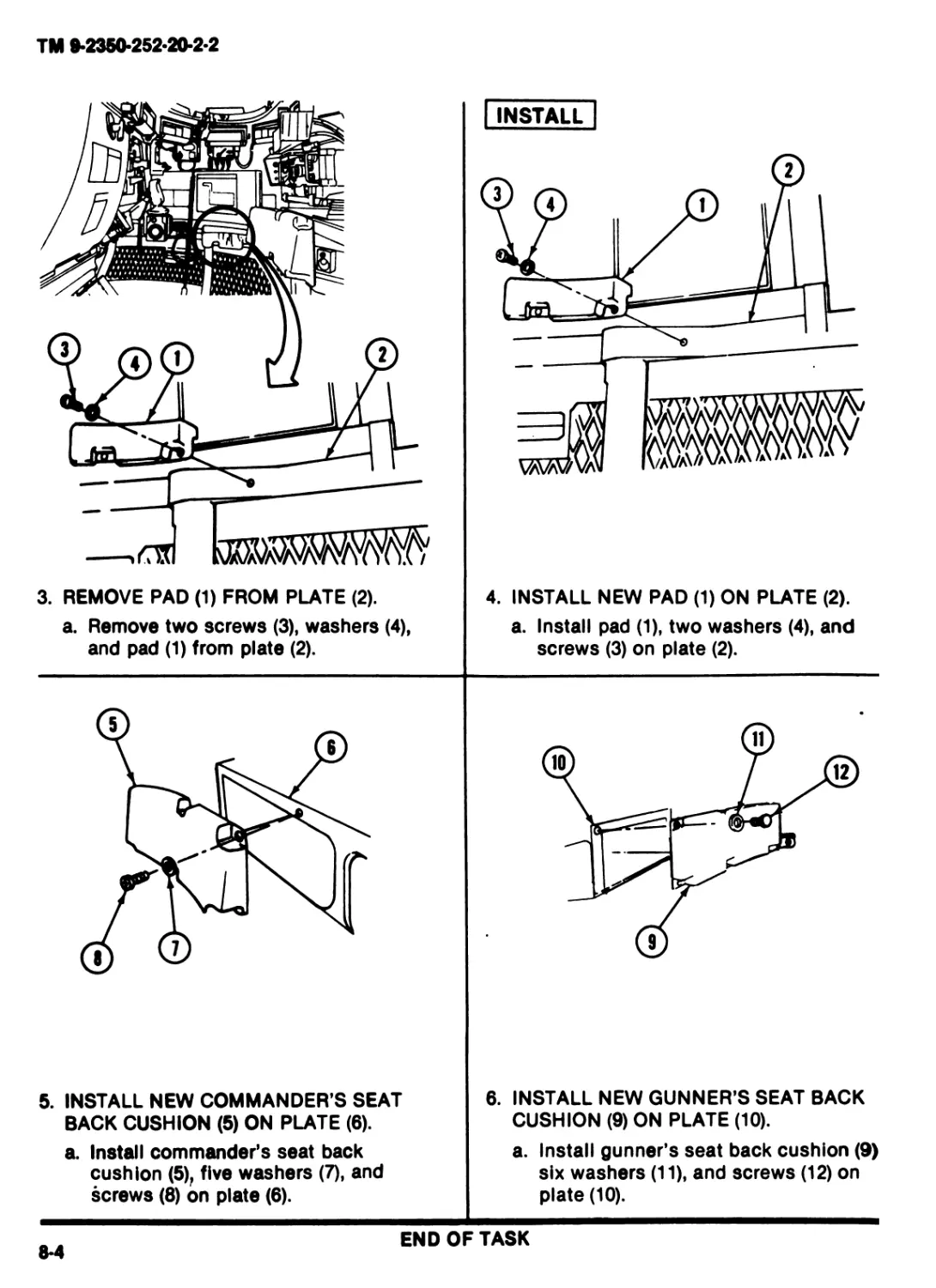
ADVANCE
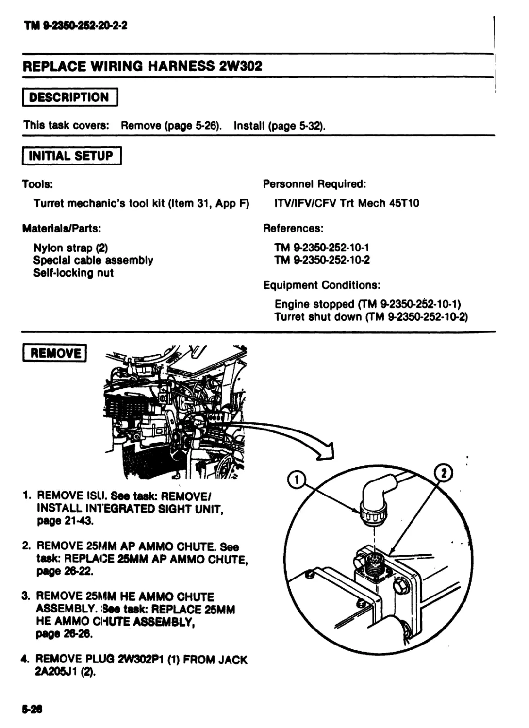
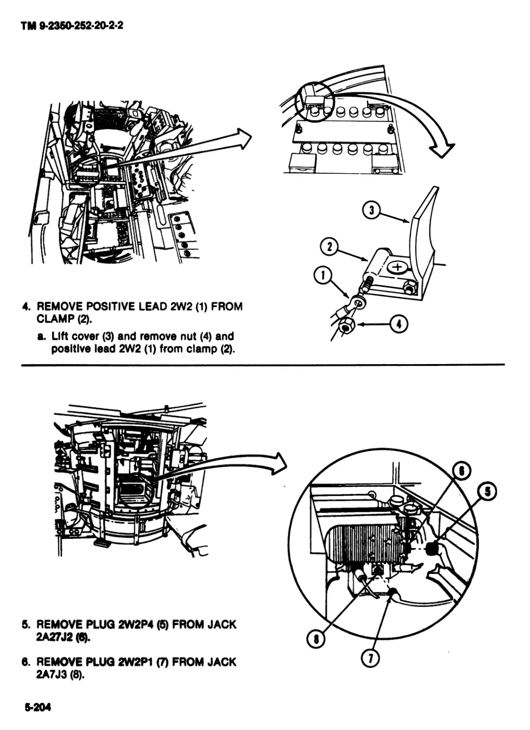
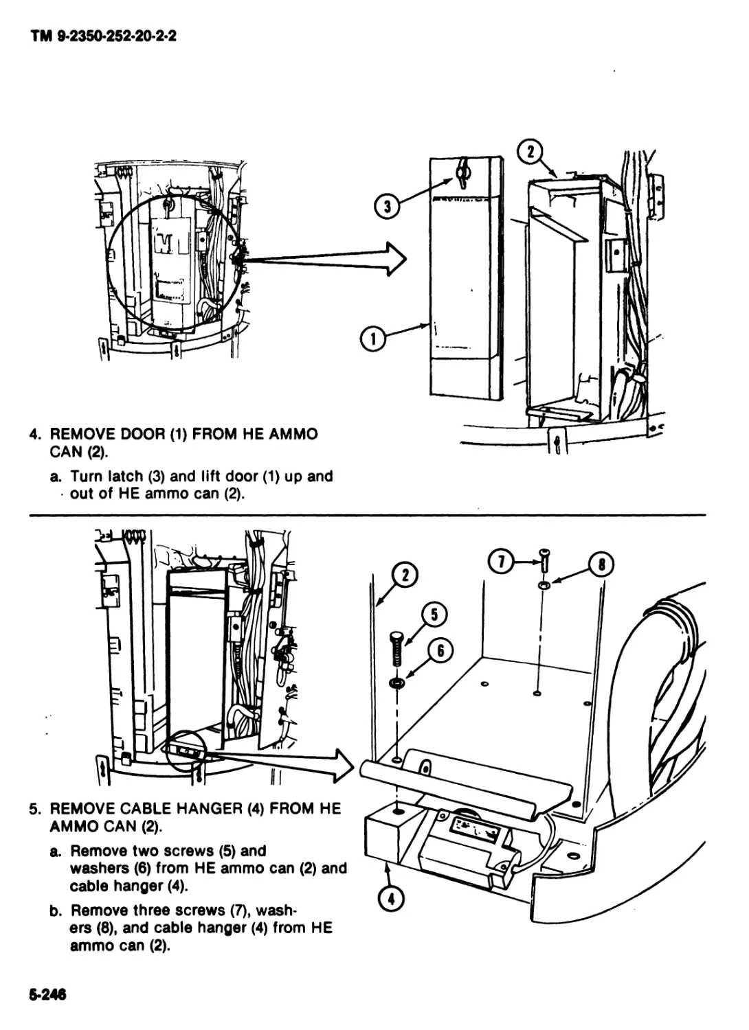
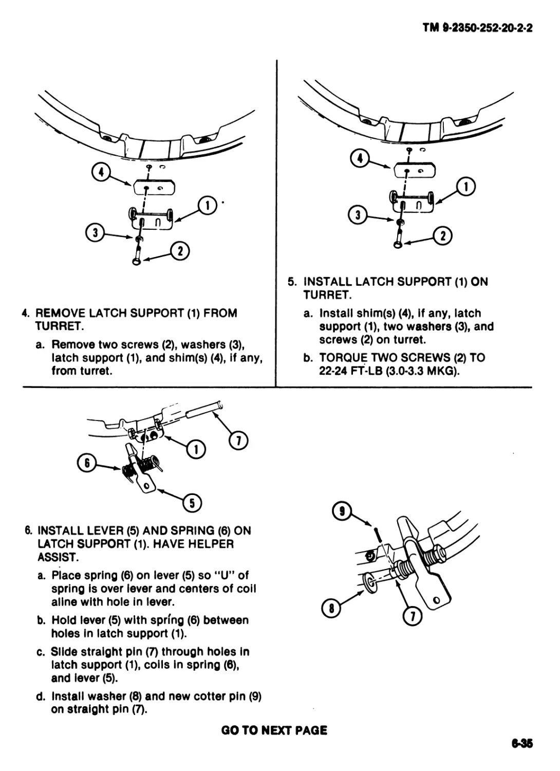
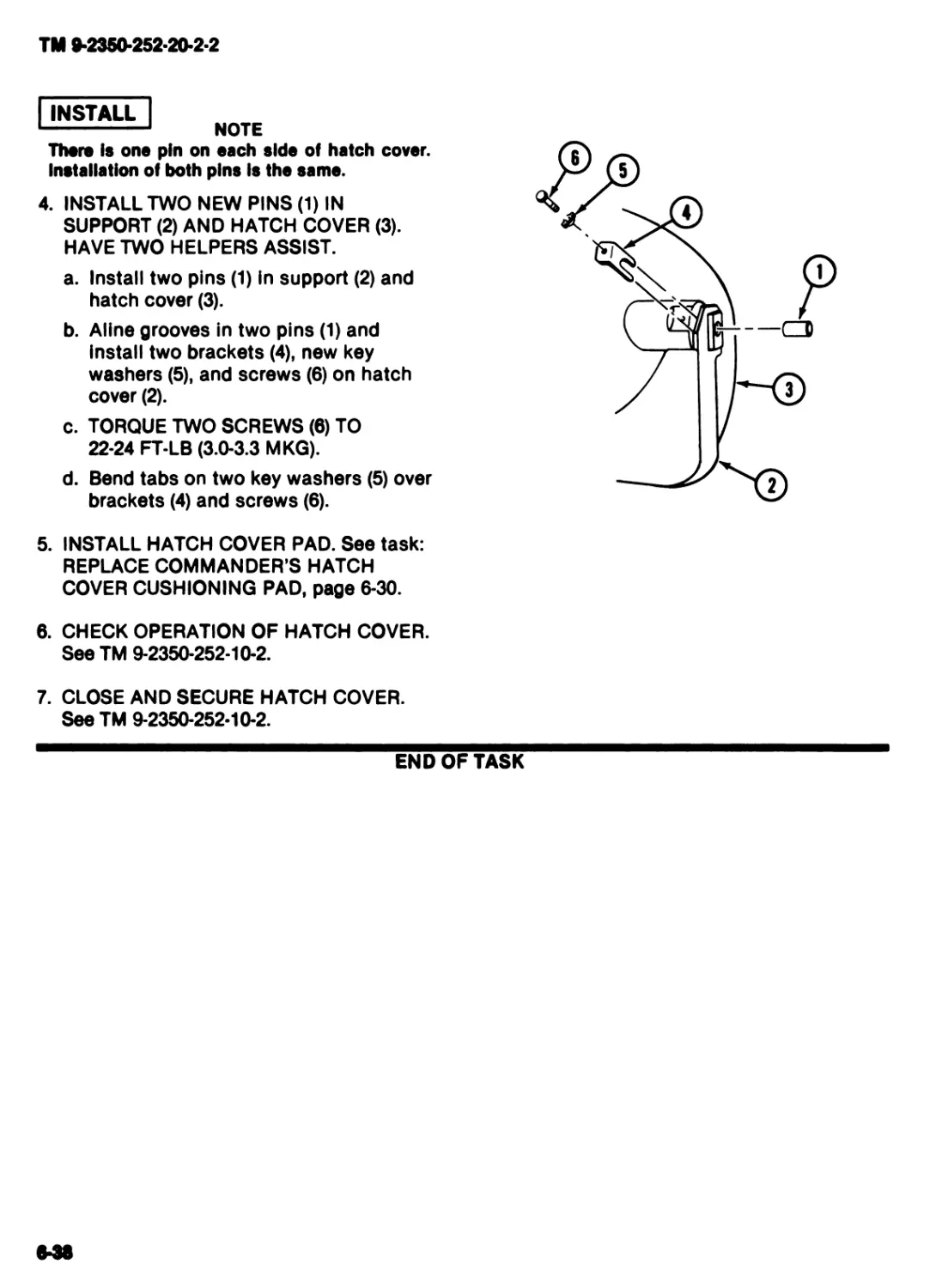
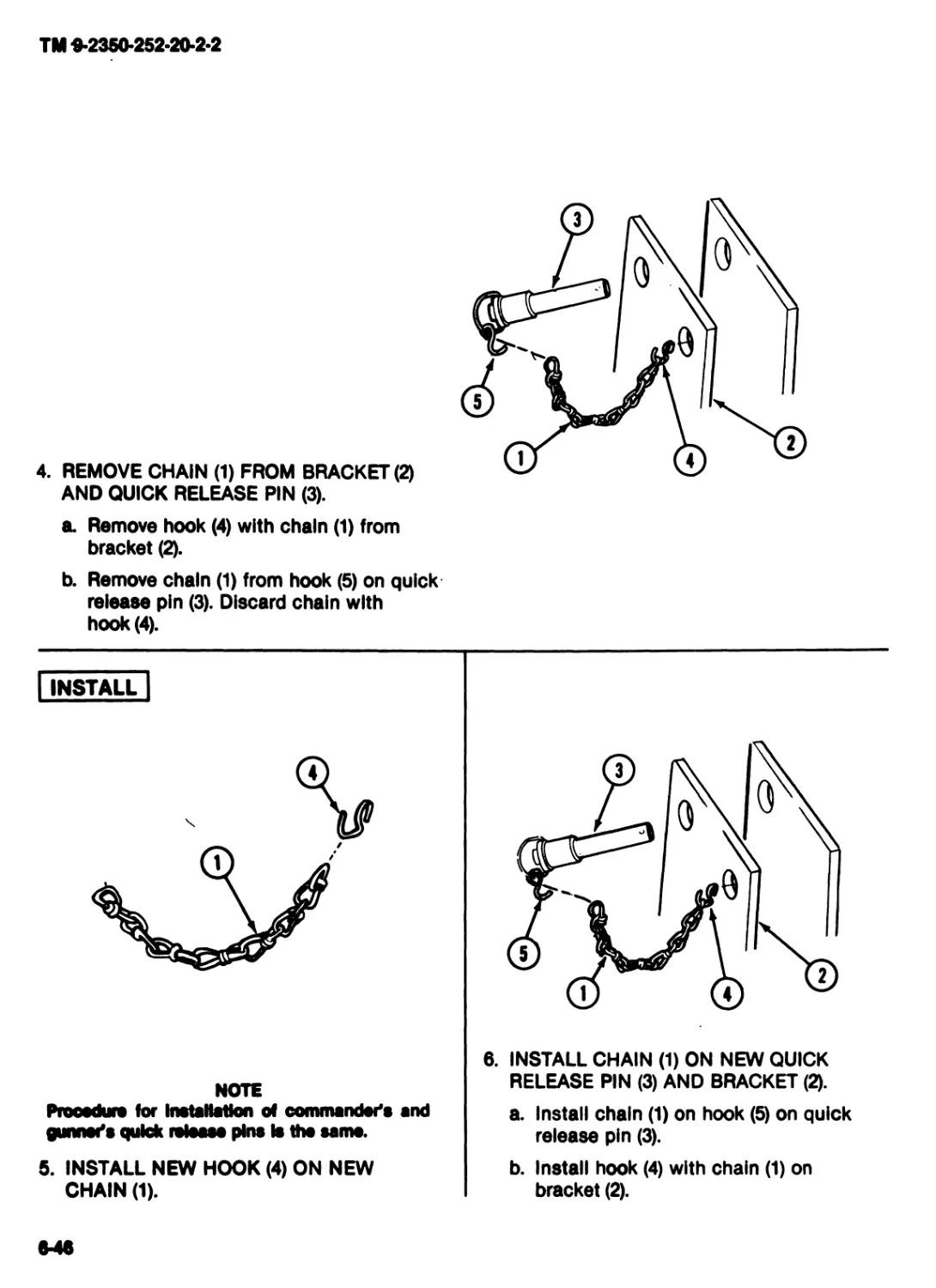
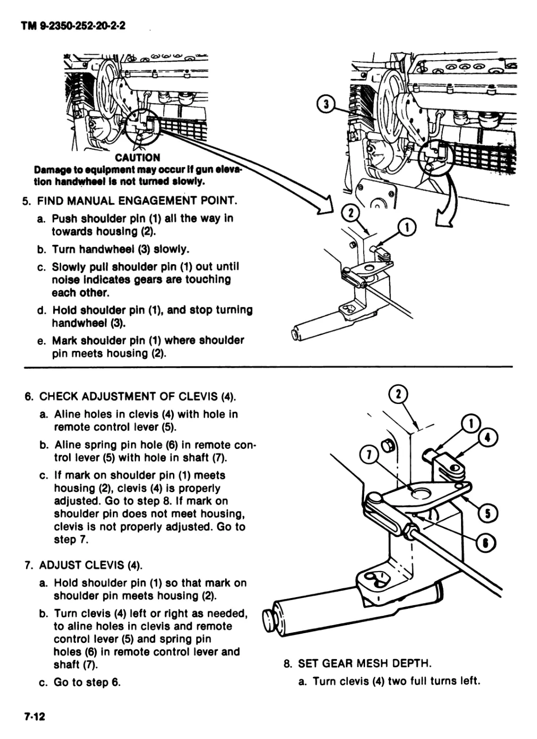
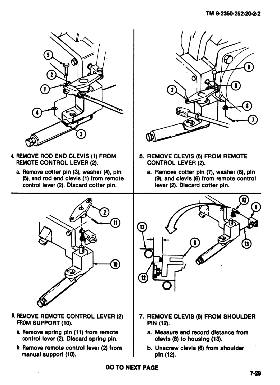
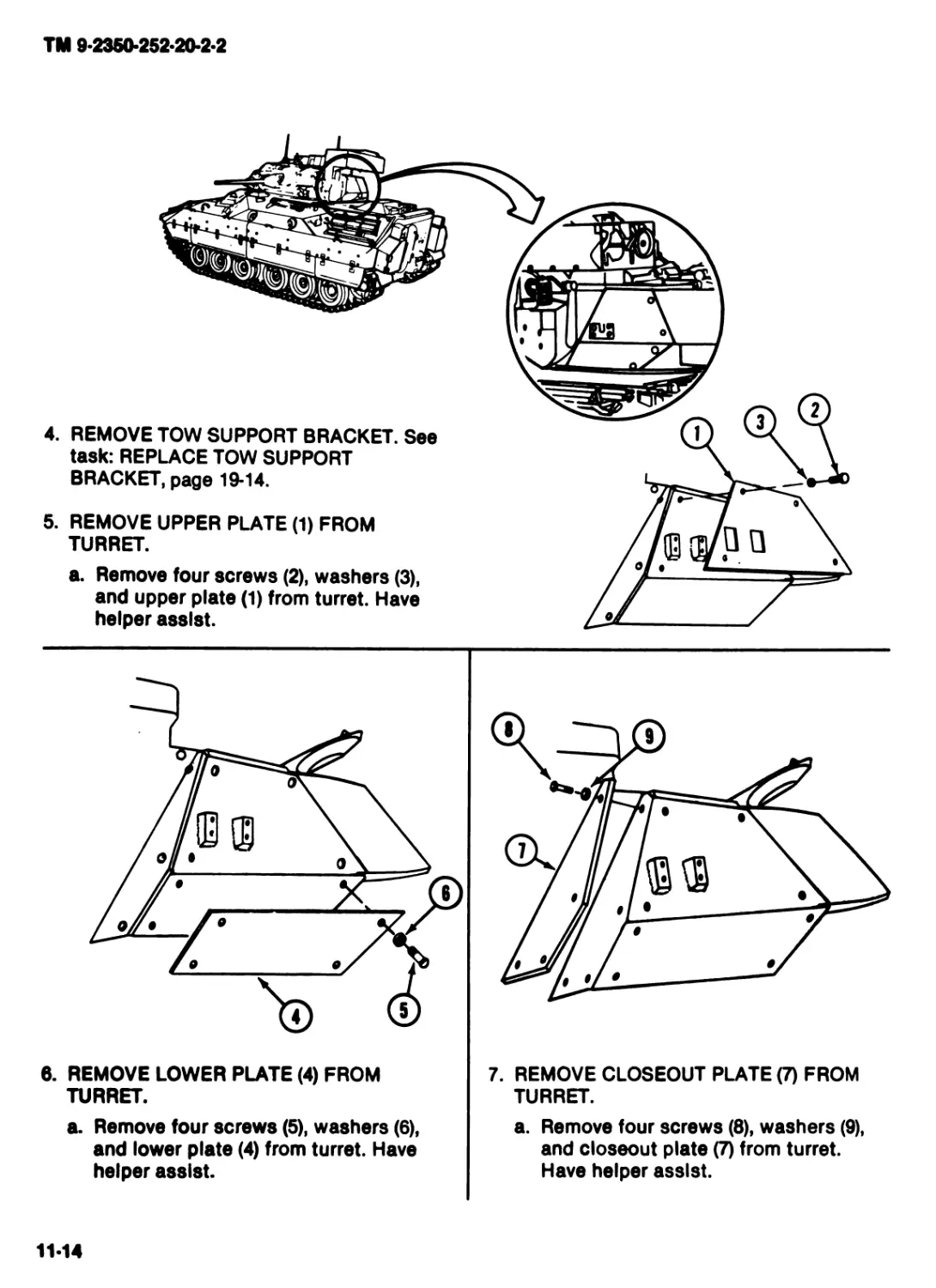
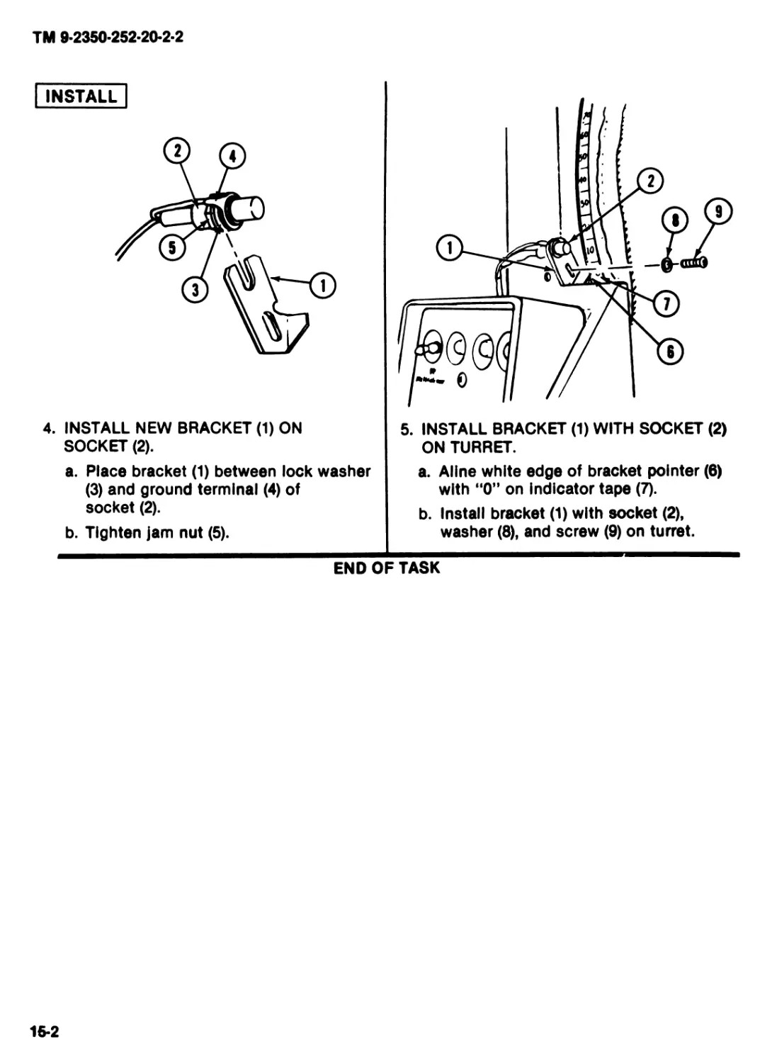
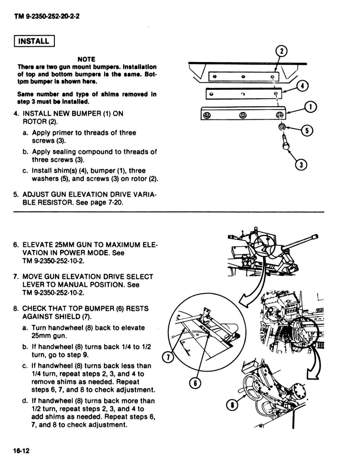
COPY
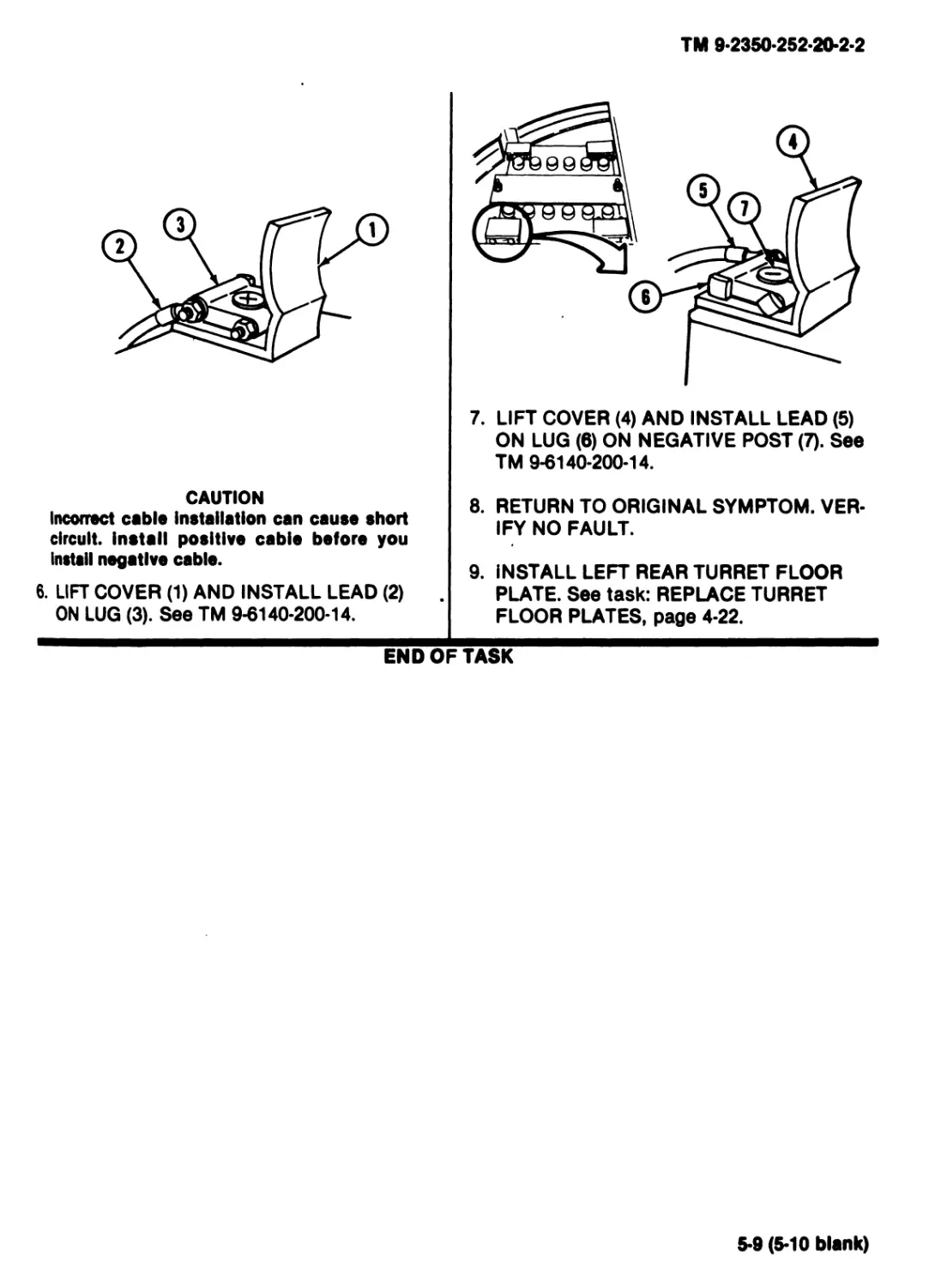
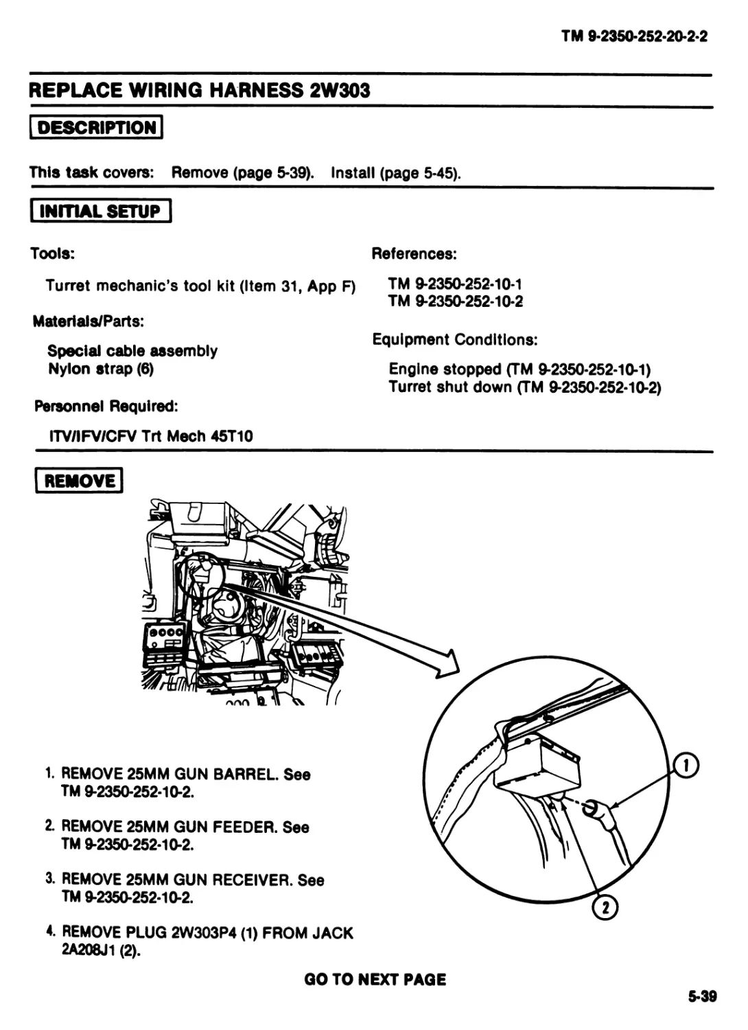
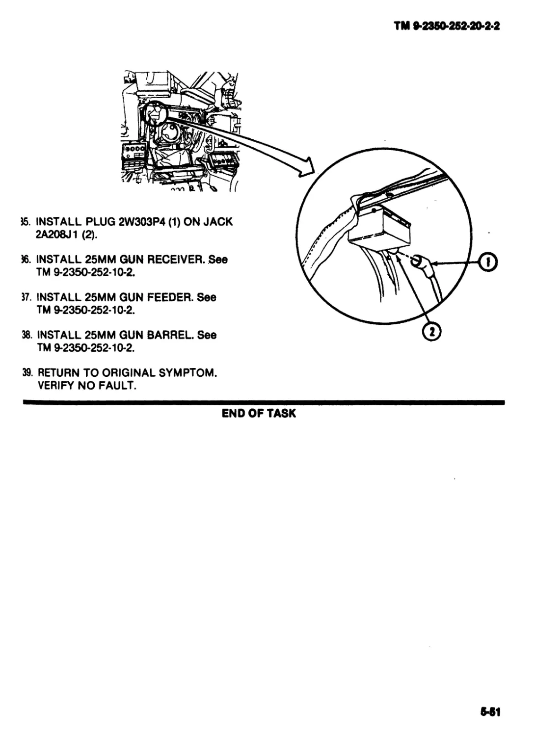
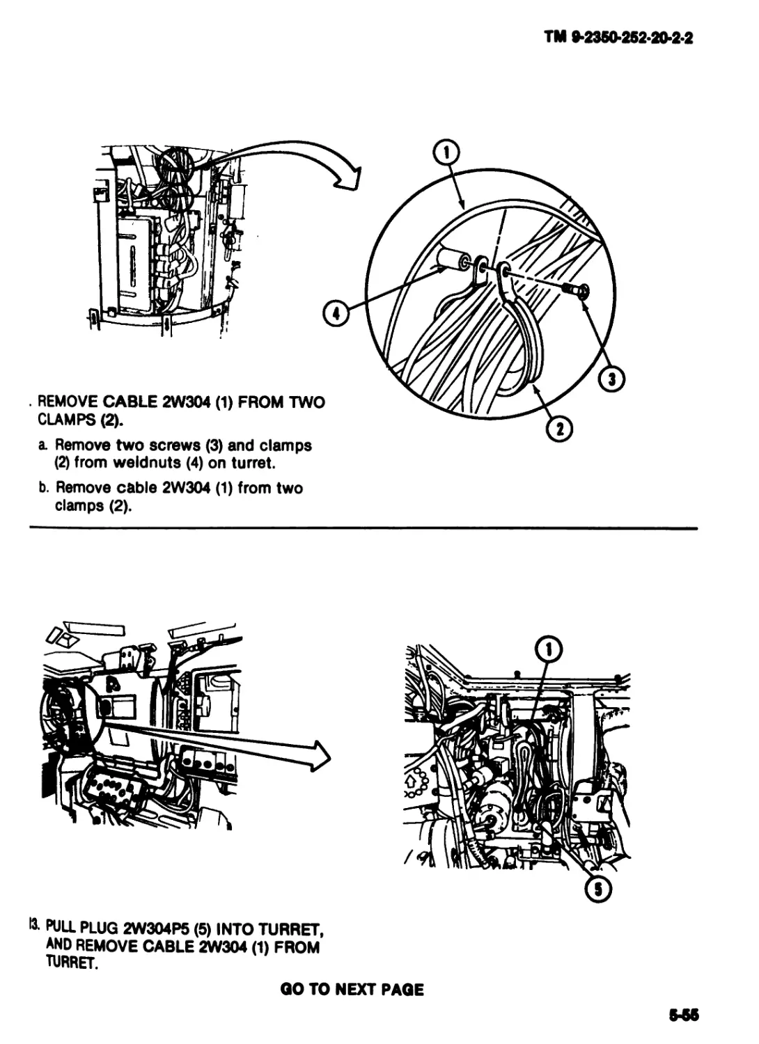
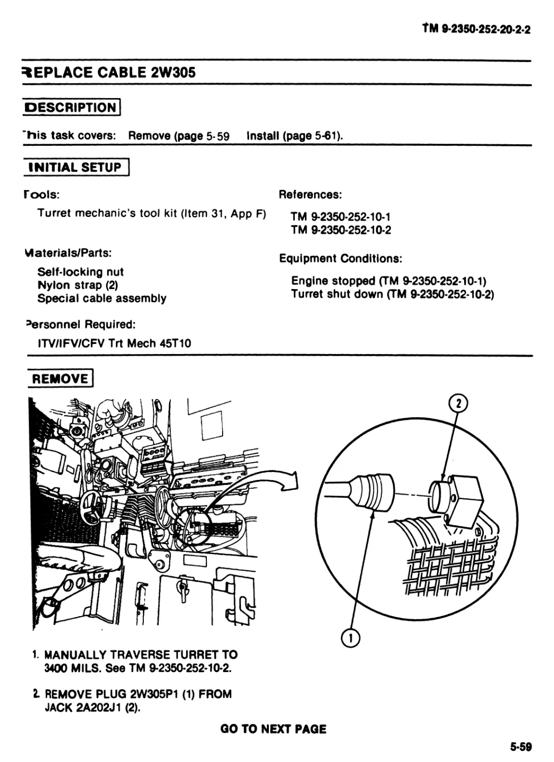
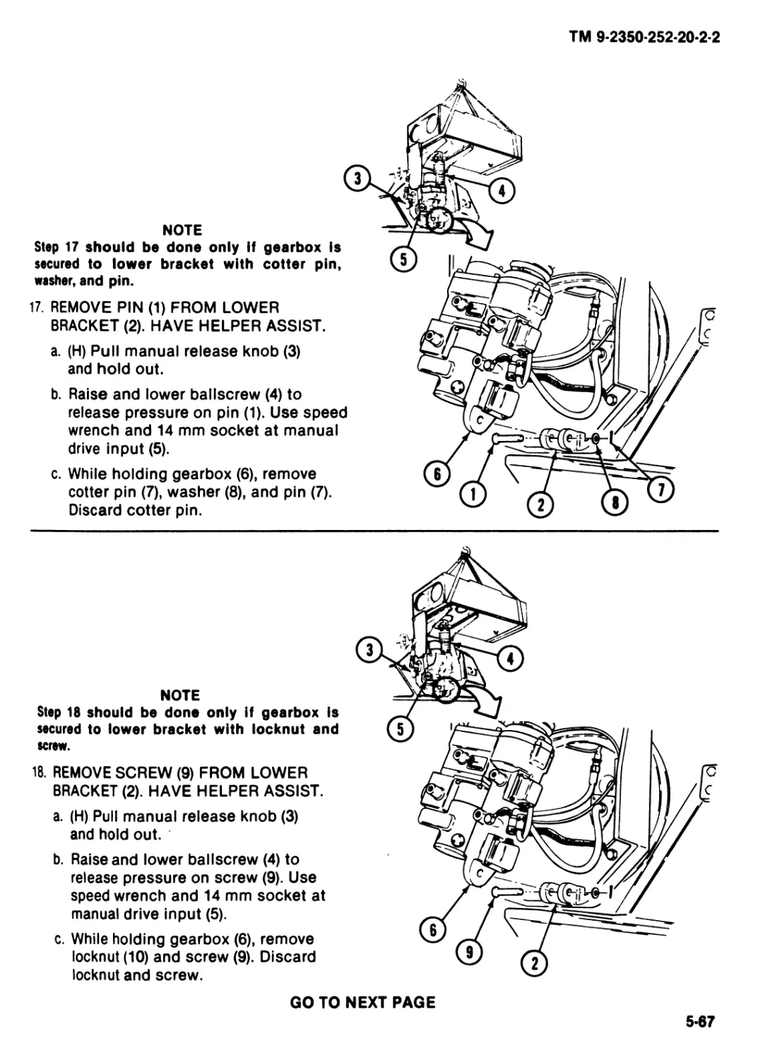
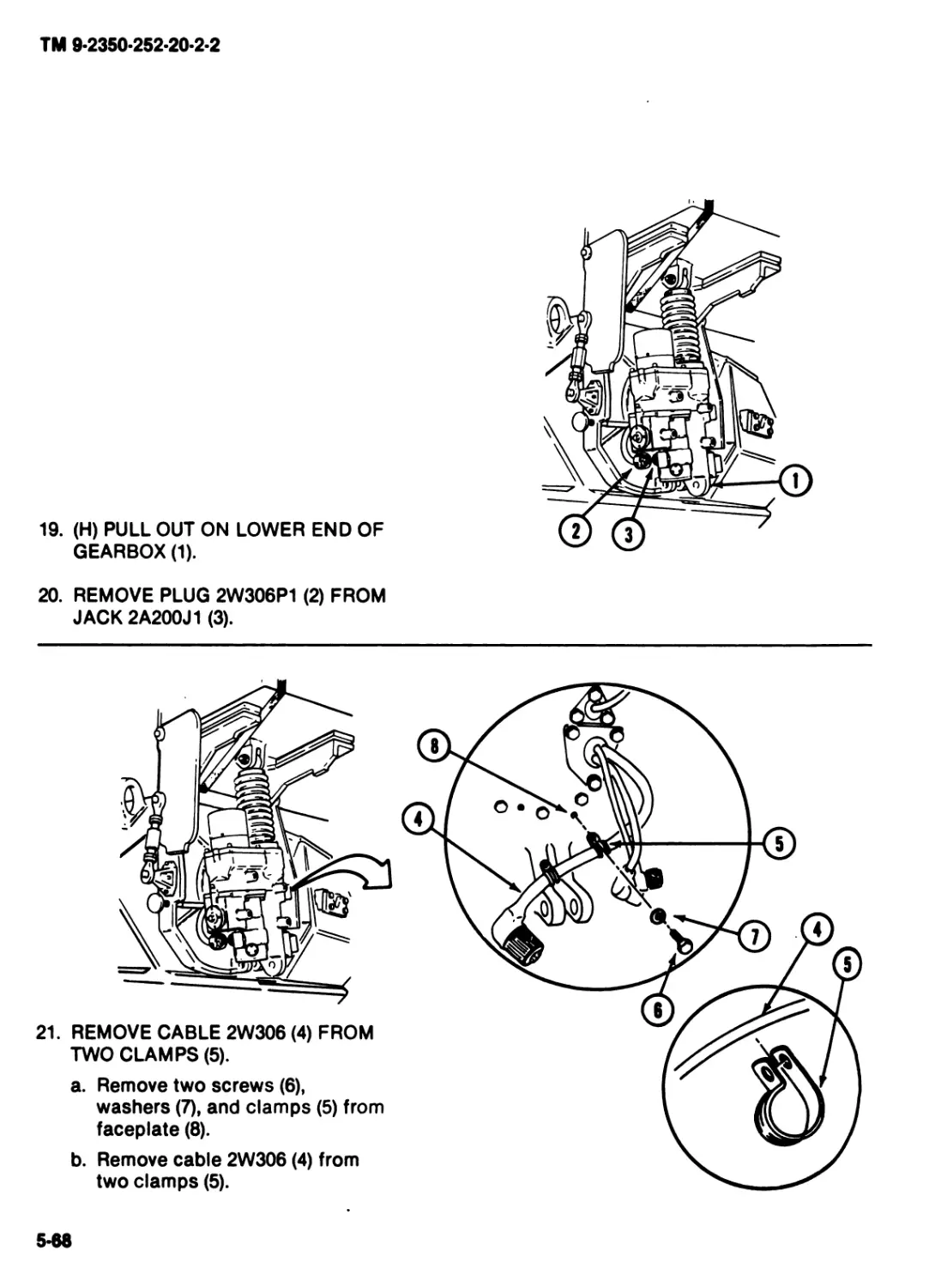
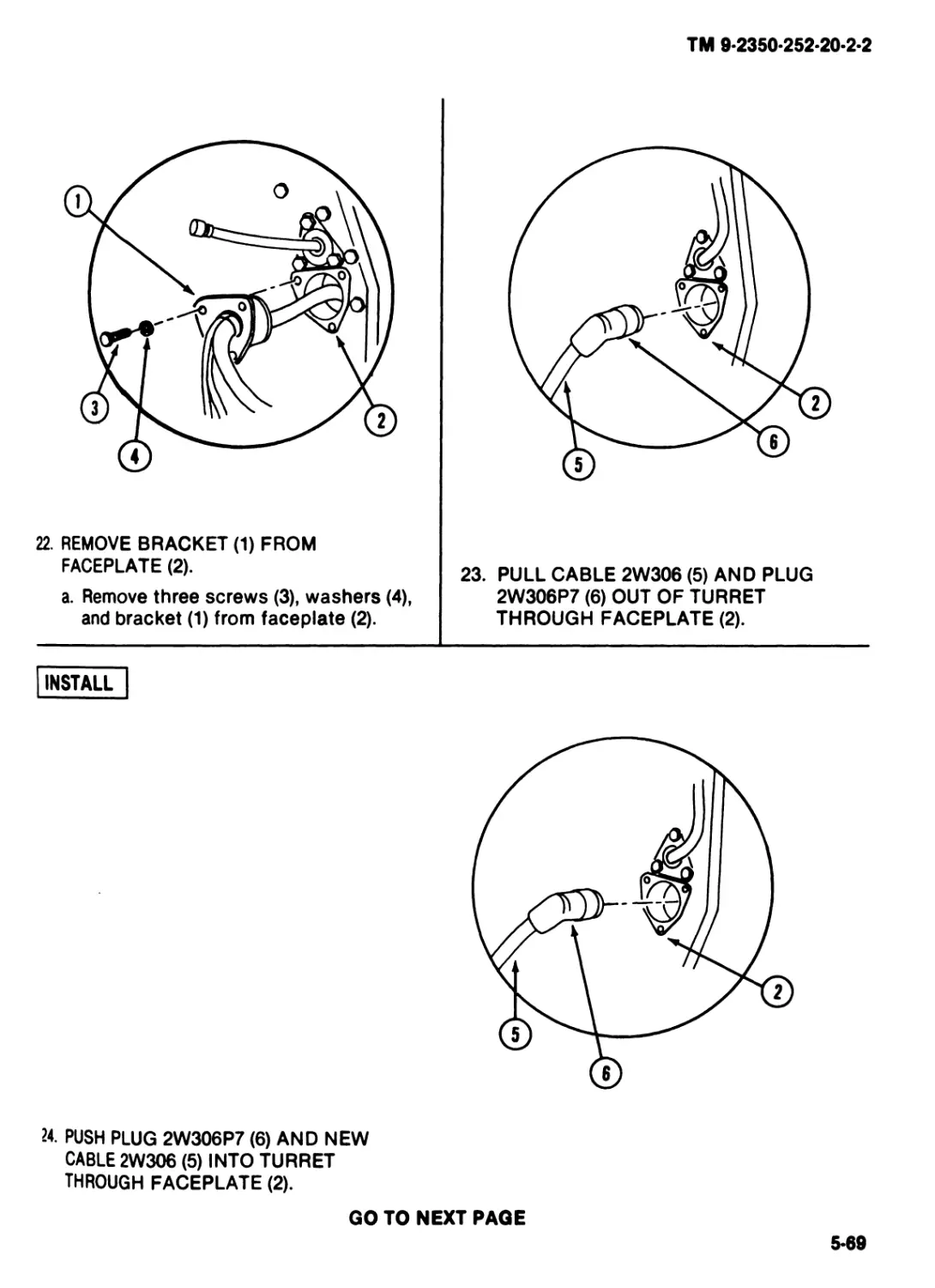
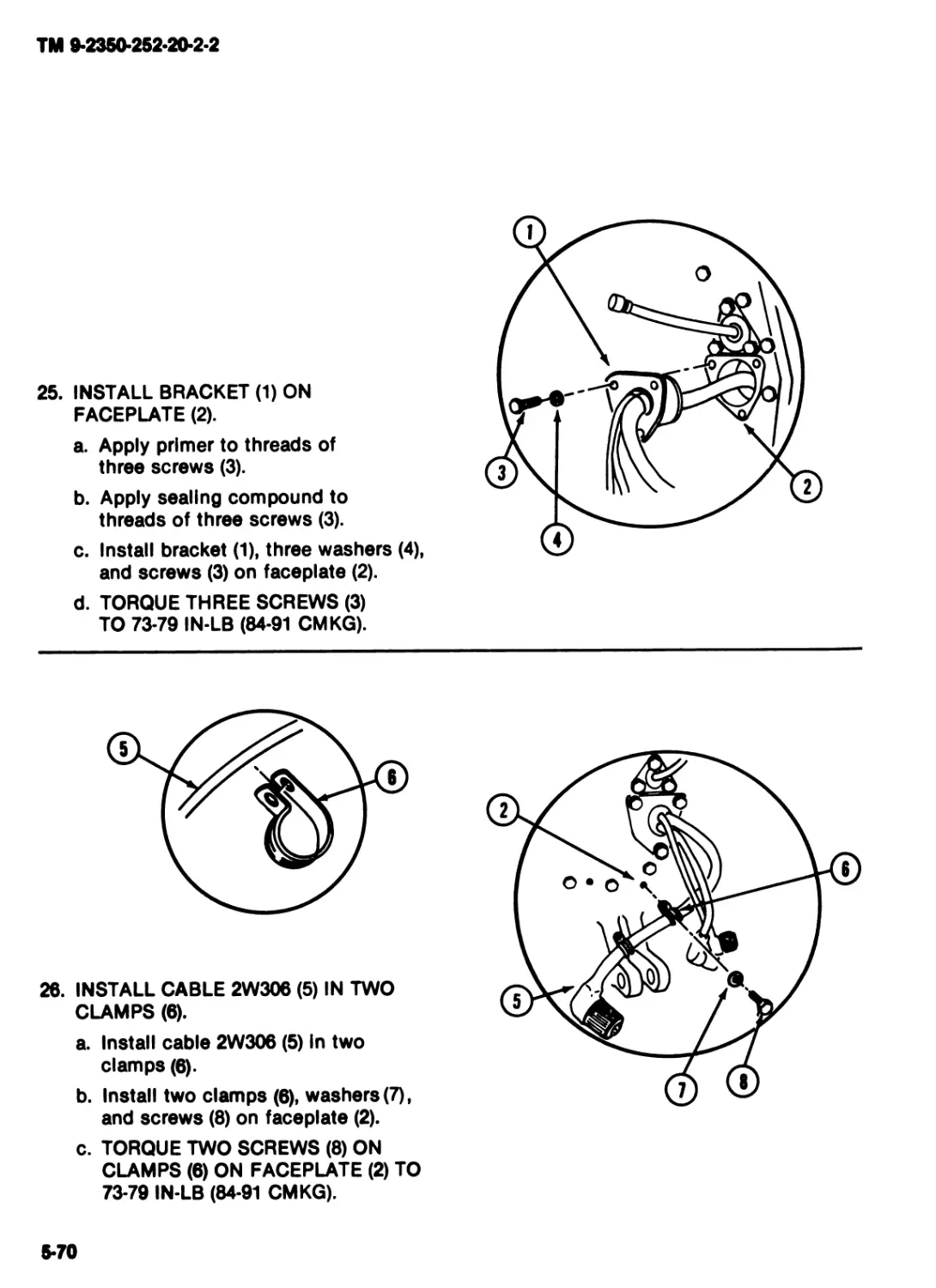
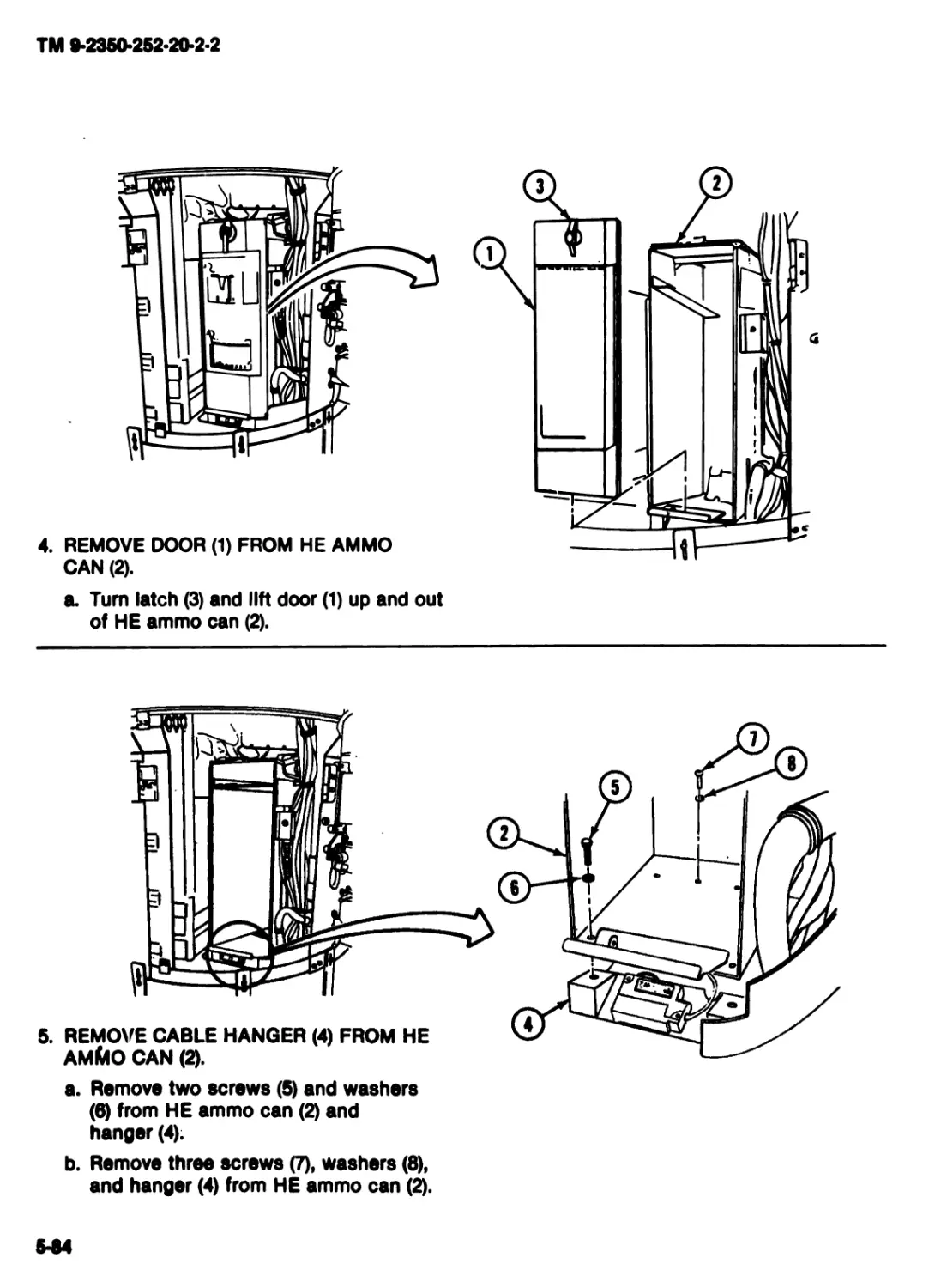
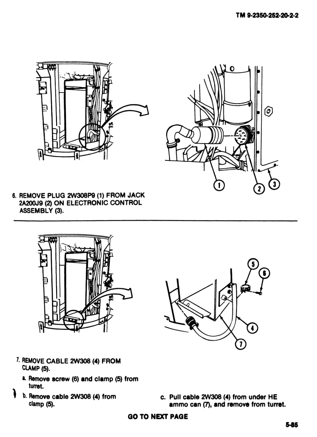
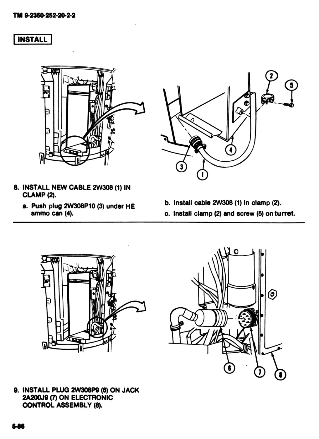
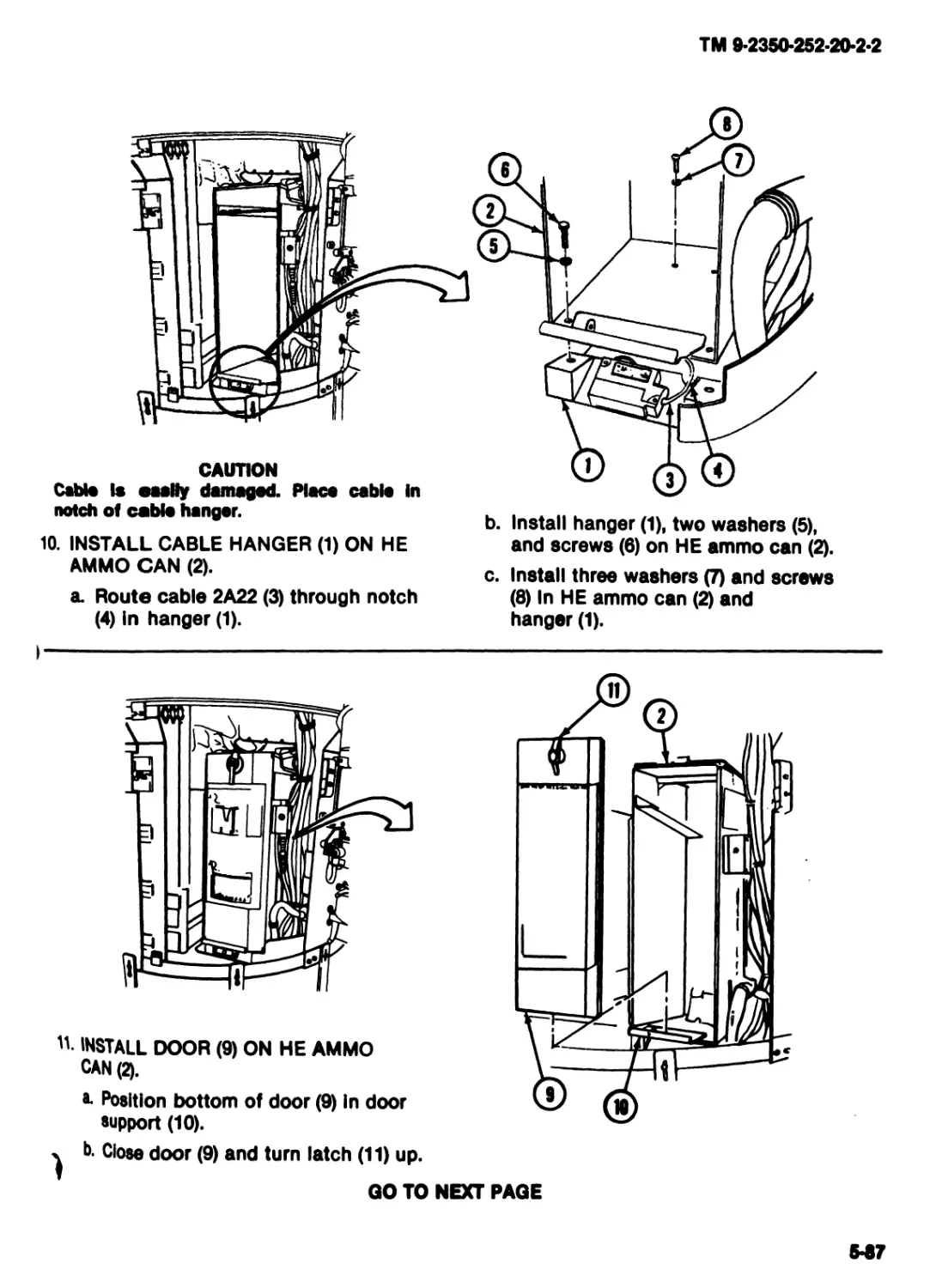
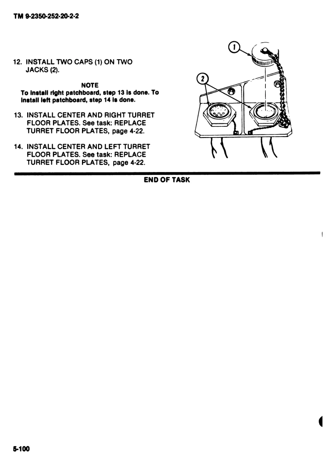
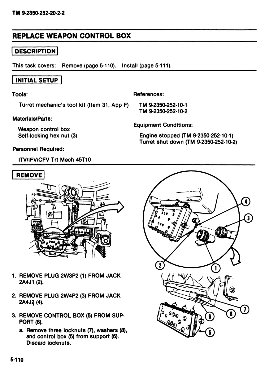
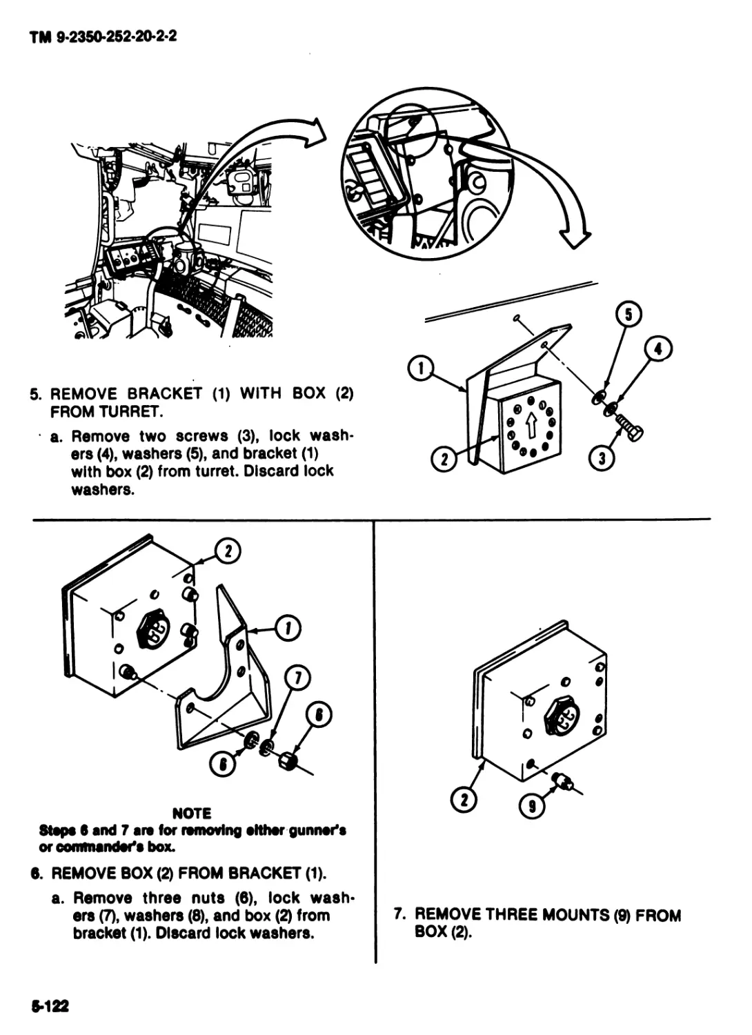
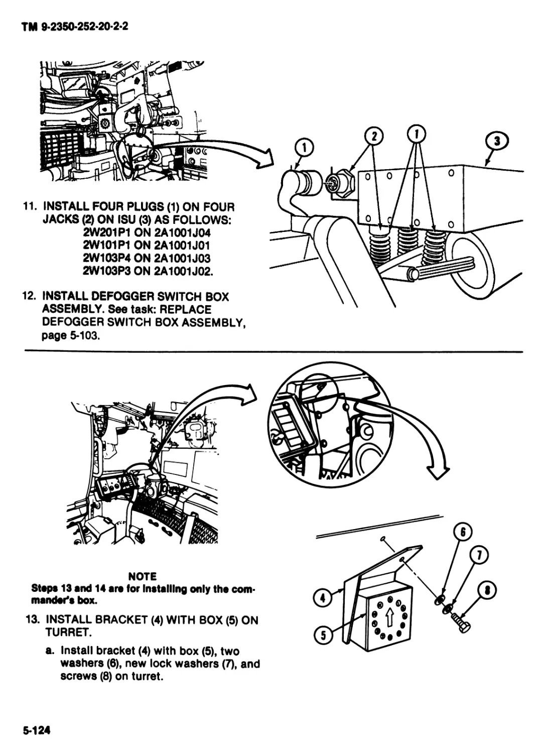
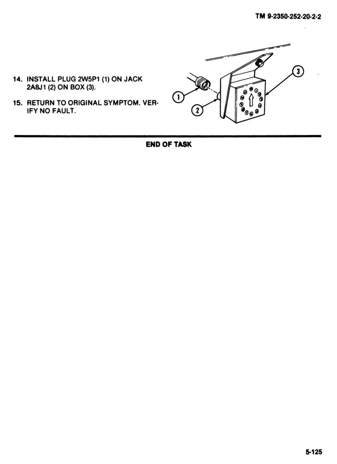
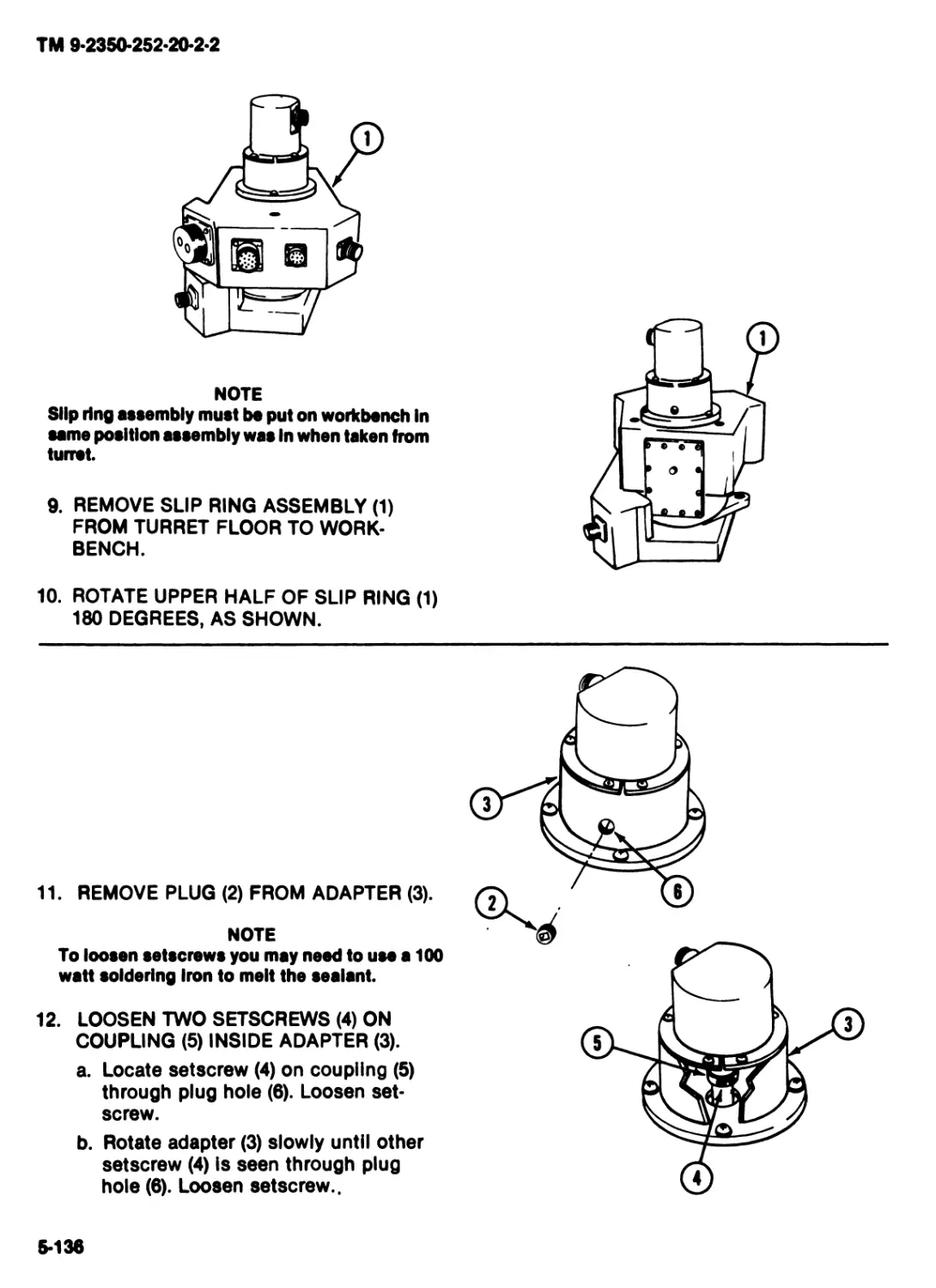
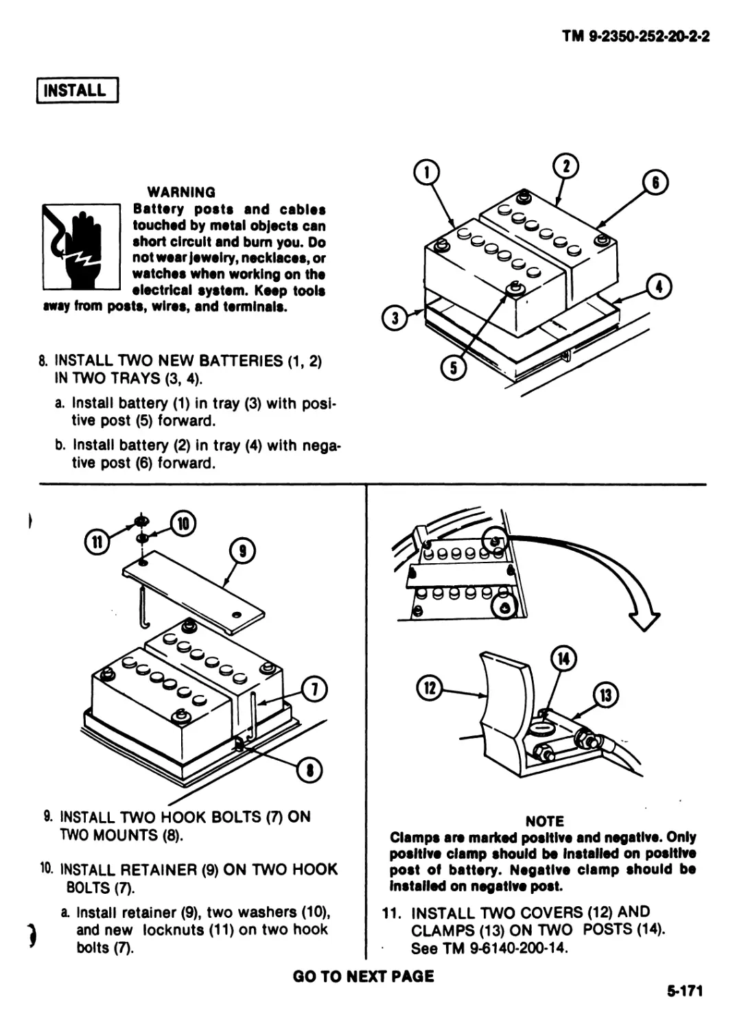
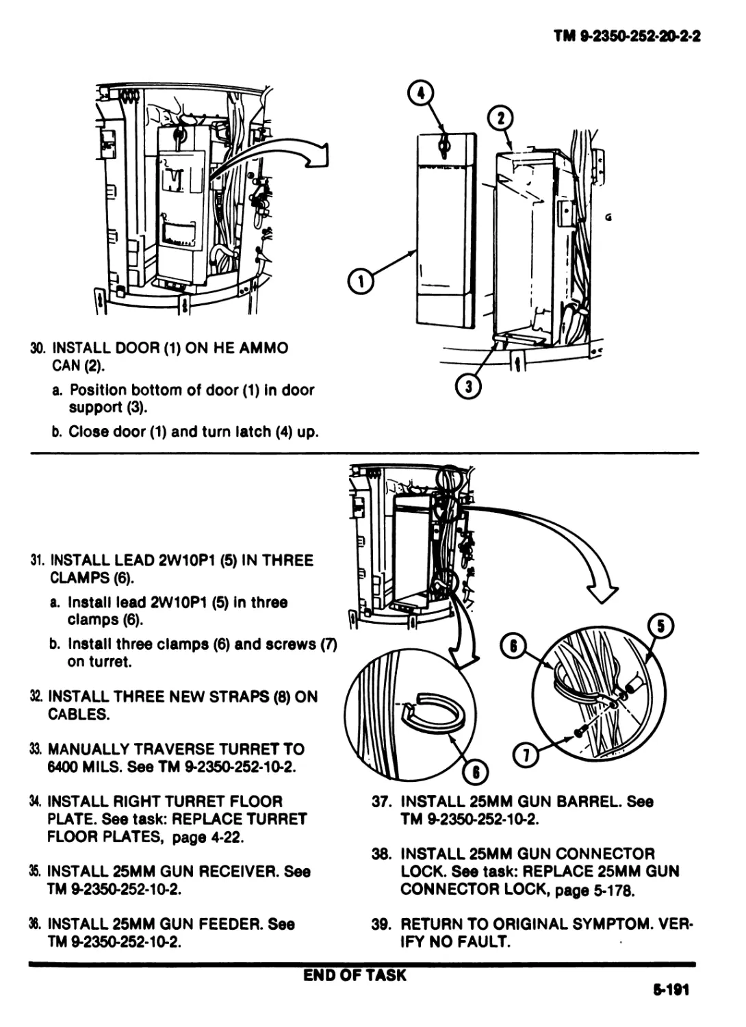
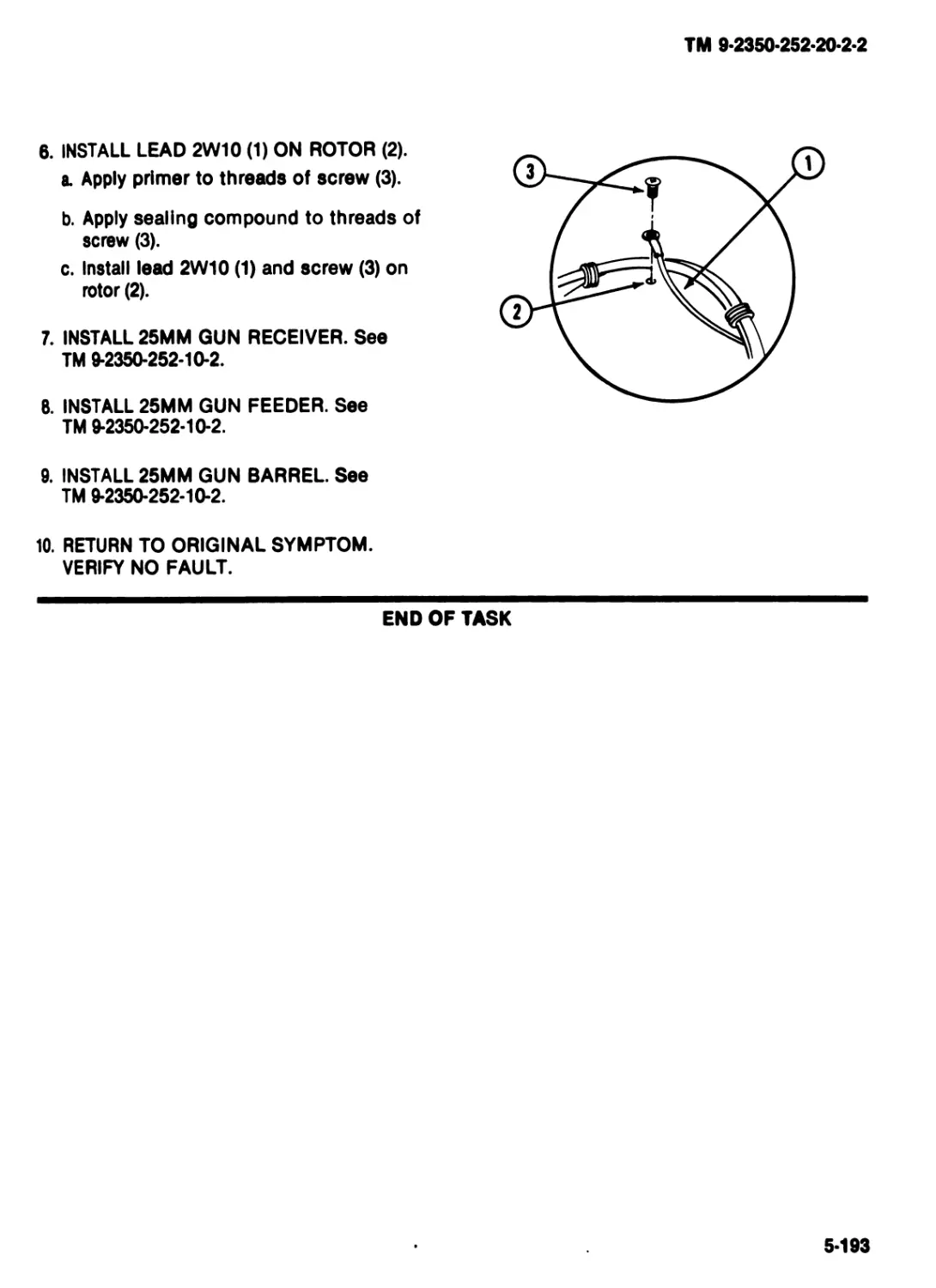
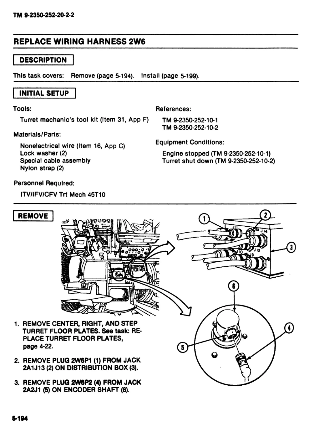
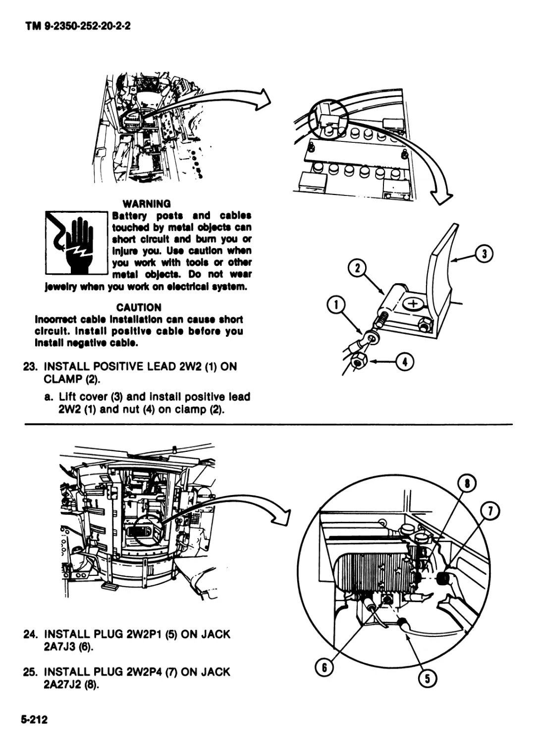
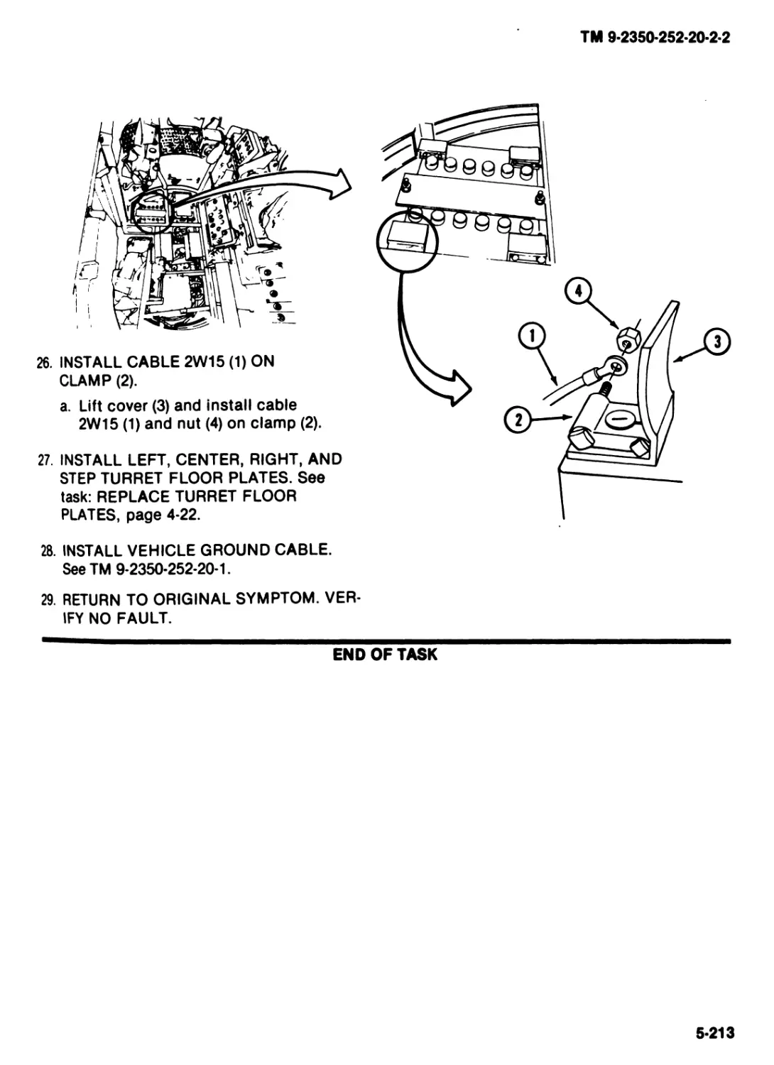
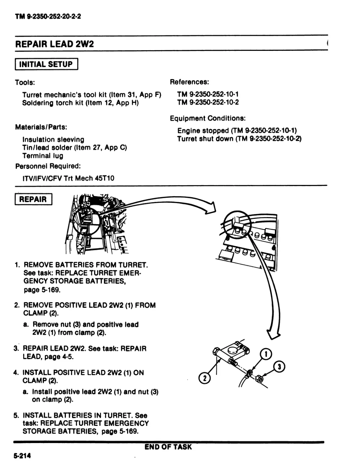
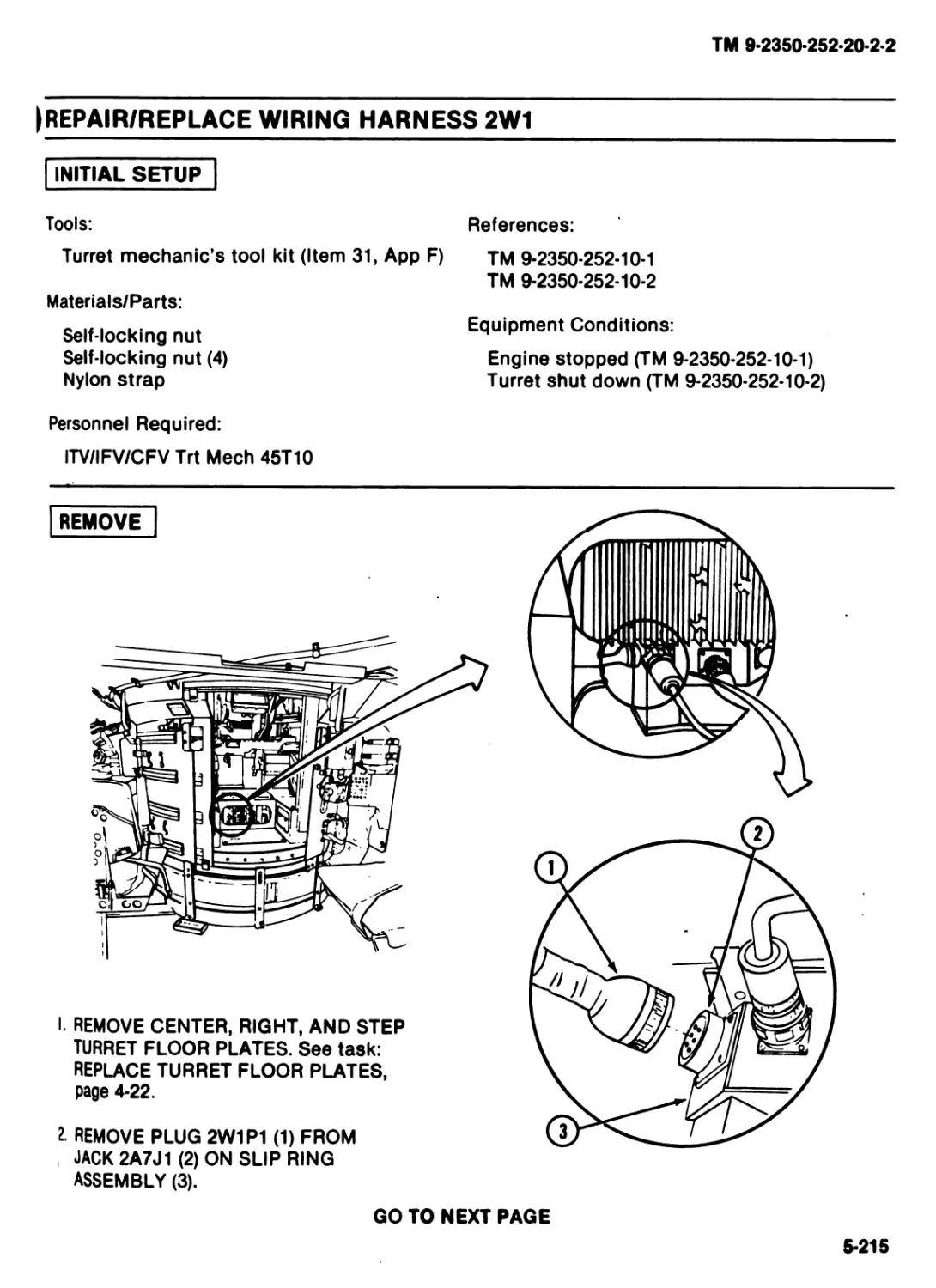
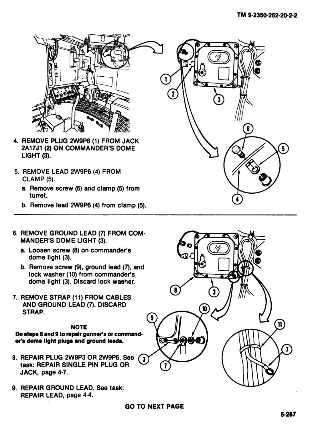
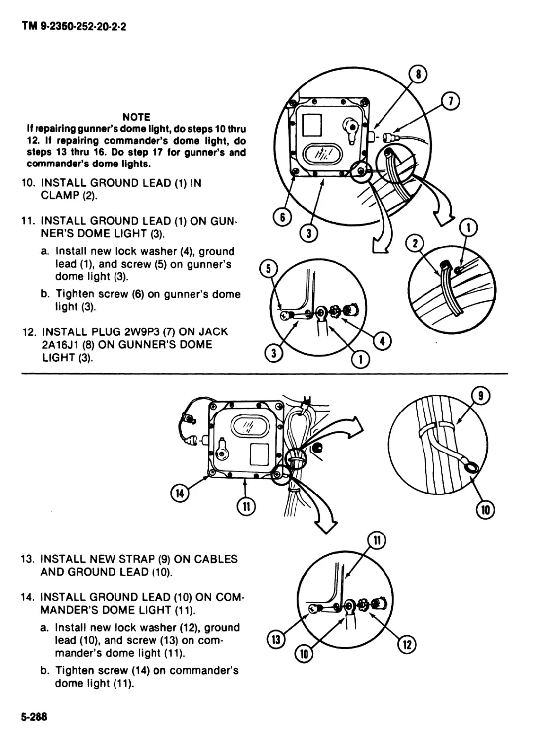
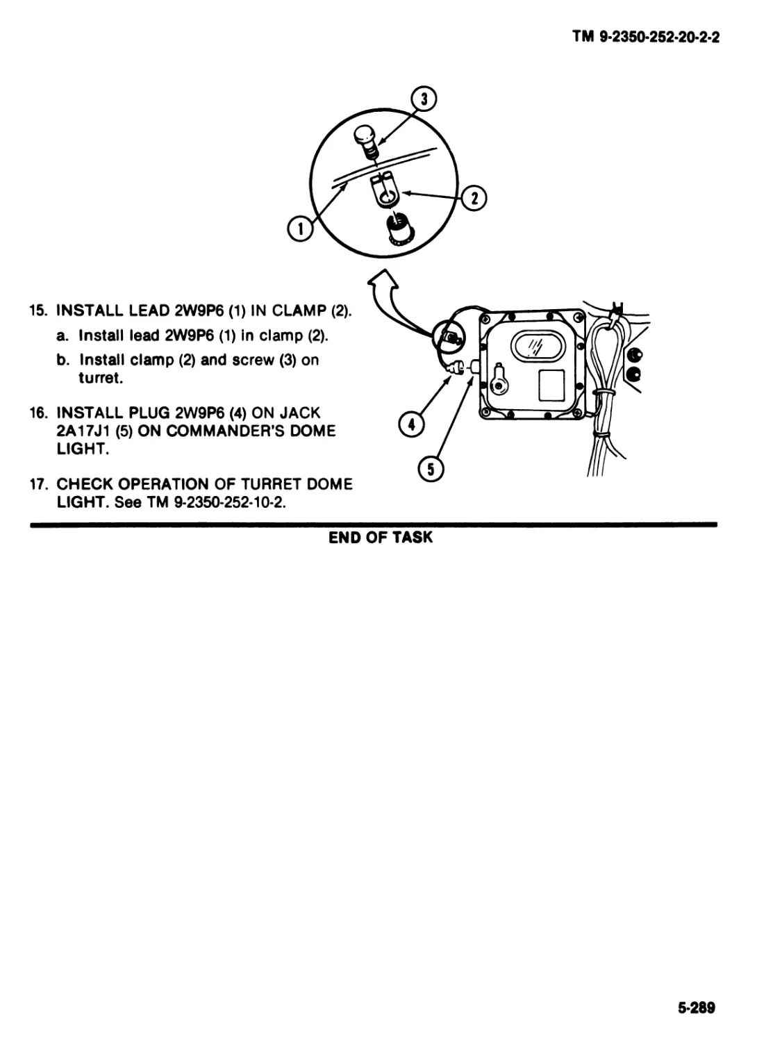
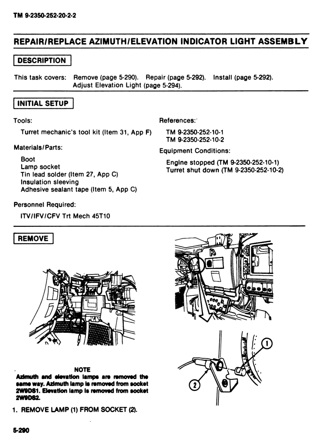
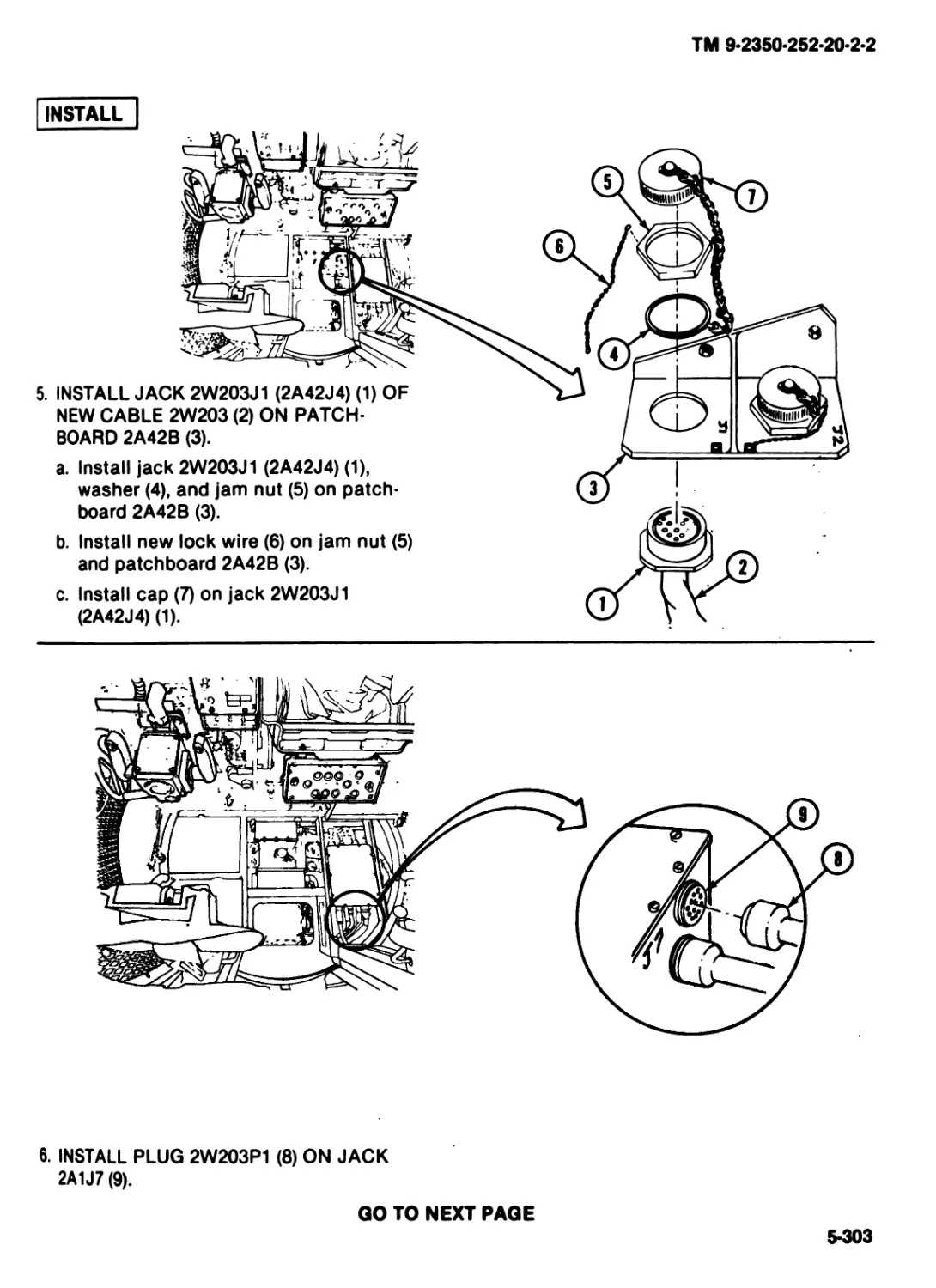
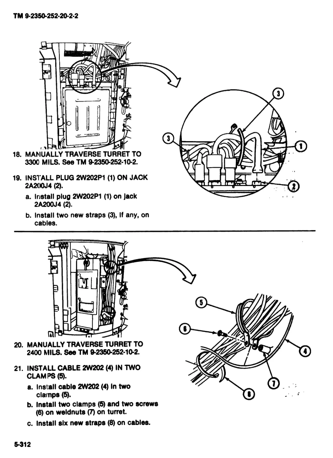
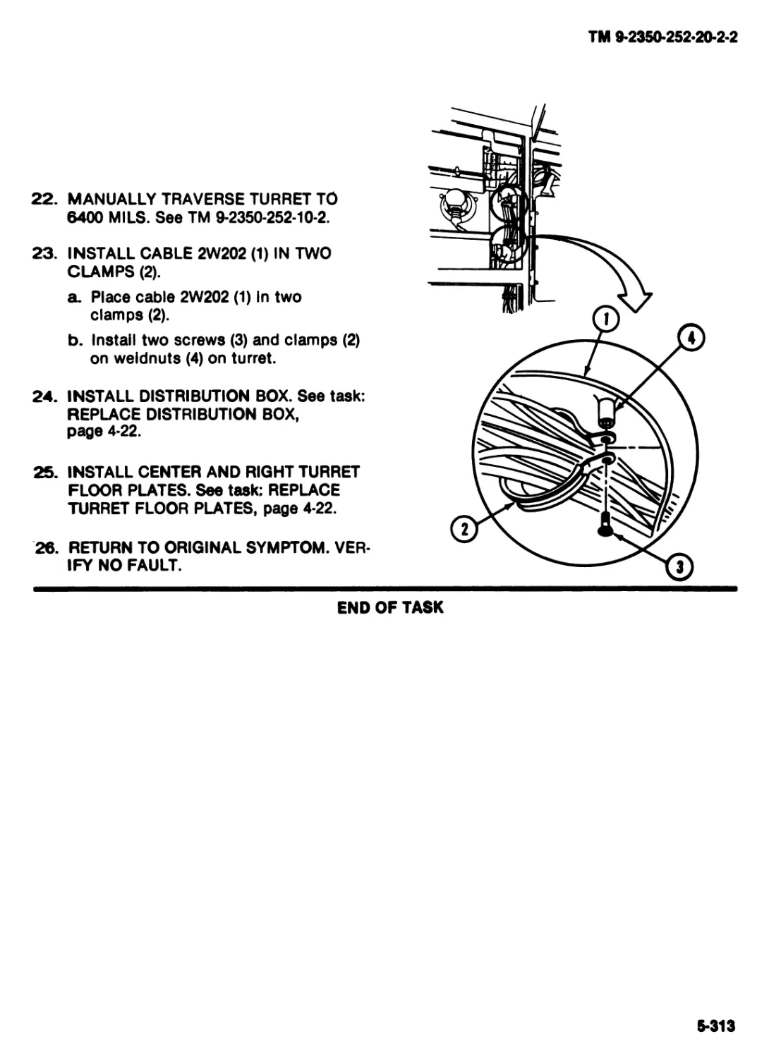
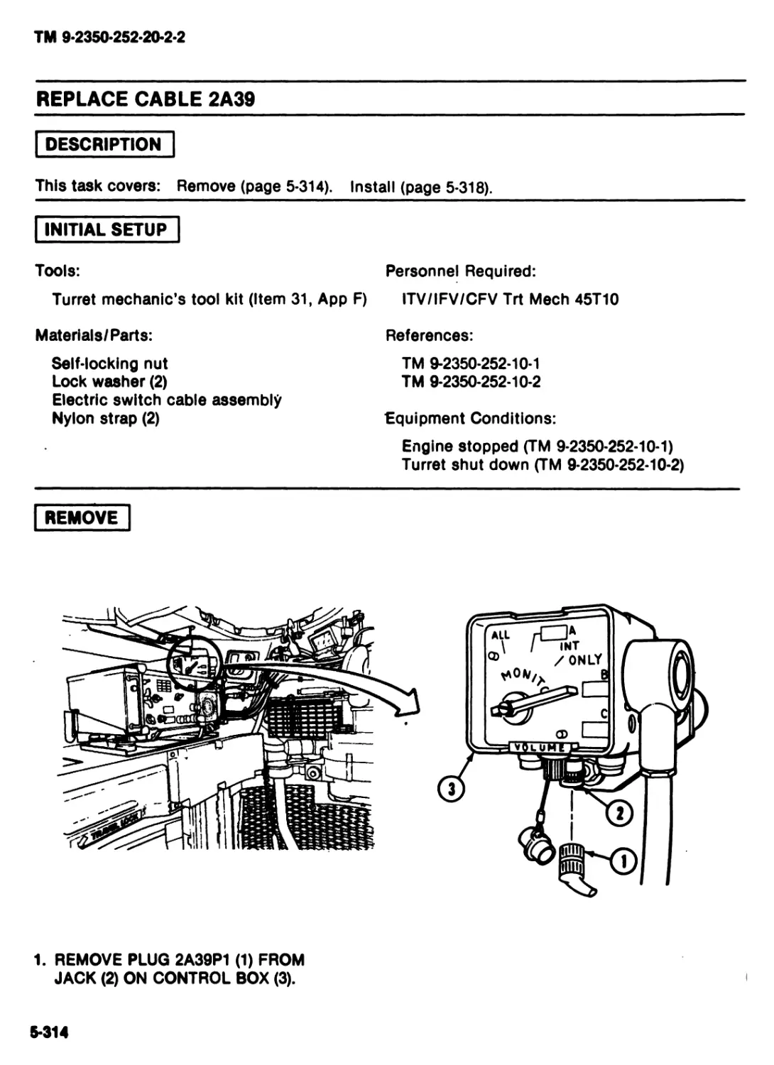
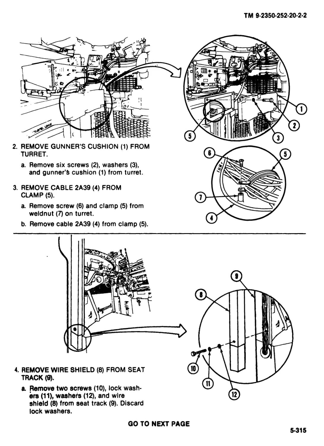
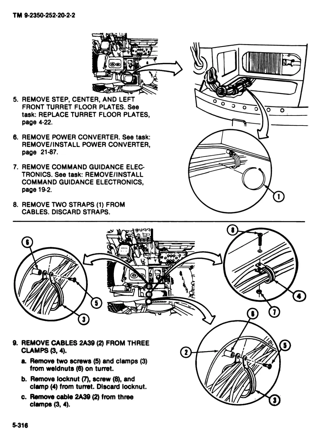
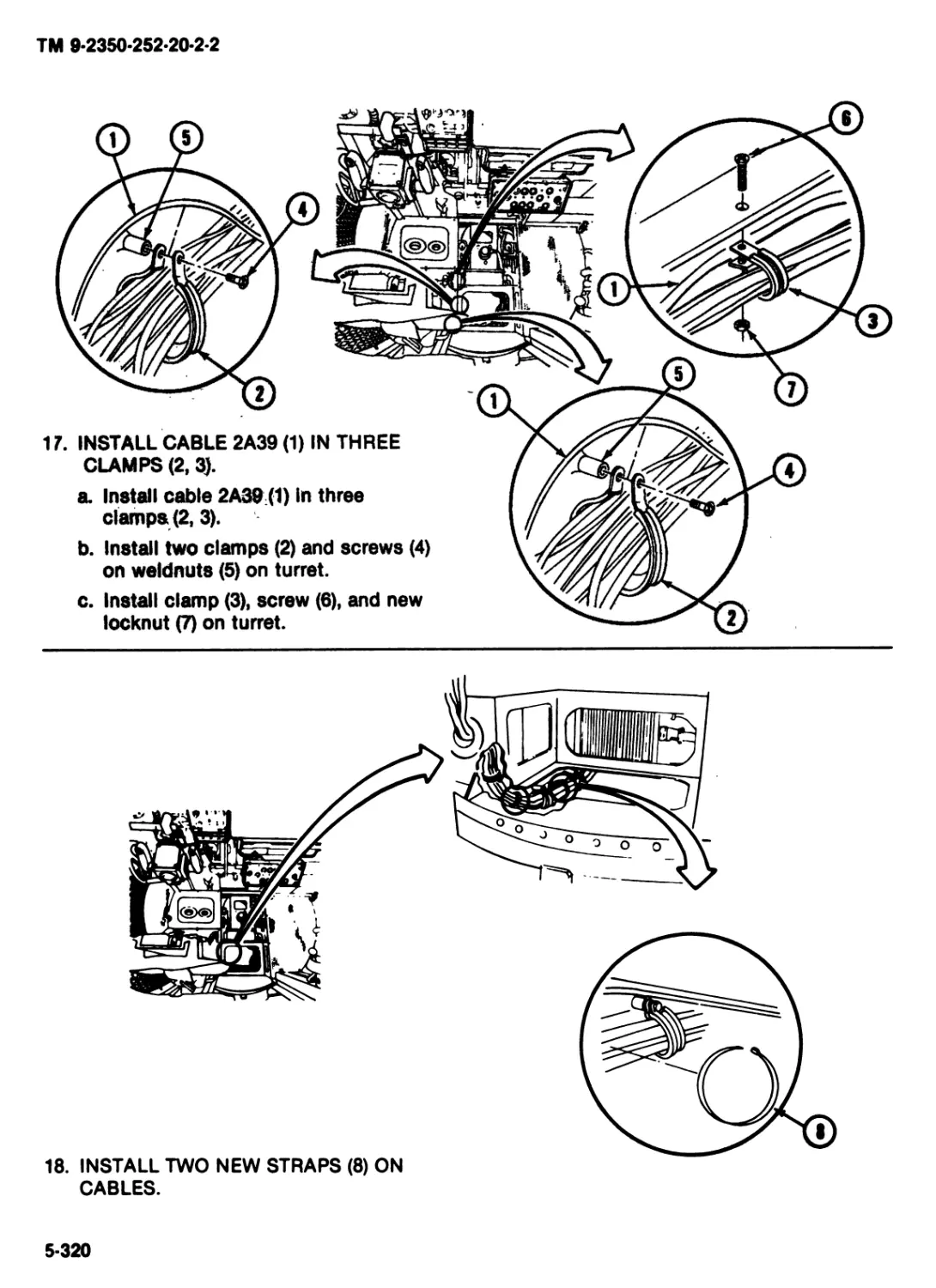
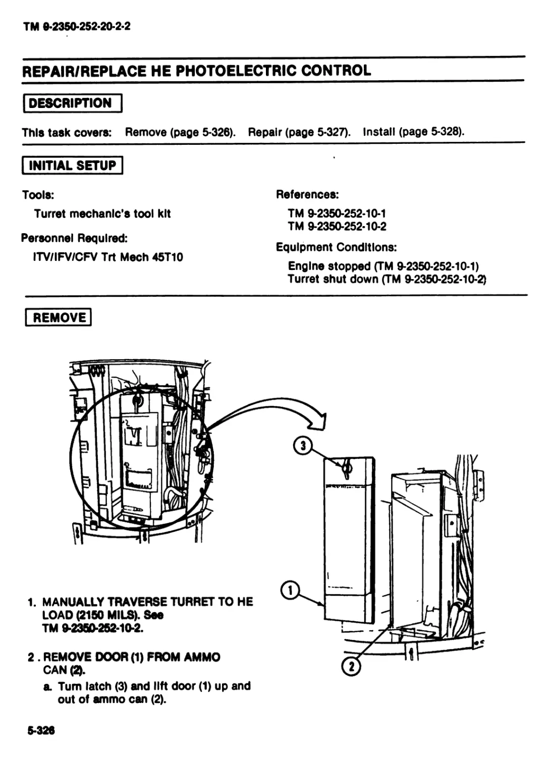
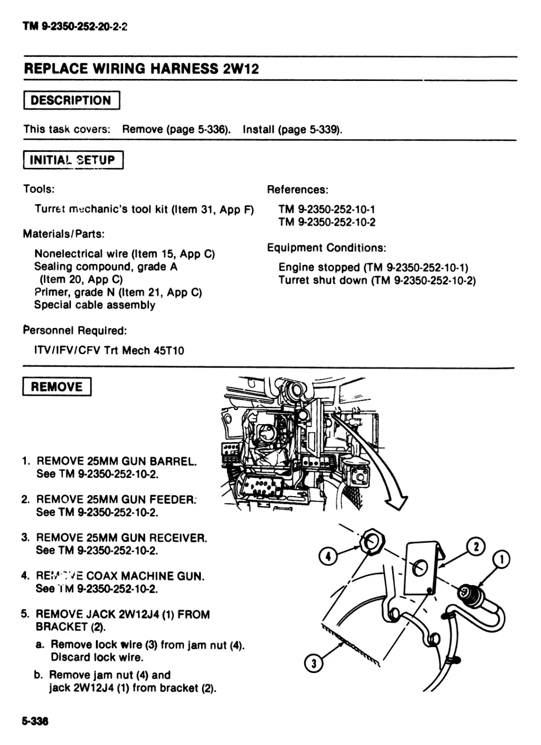
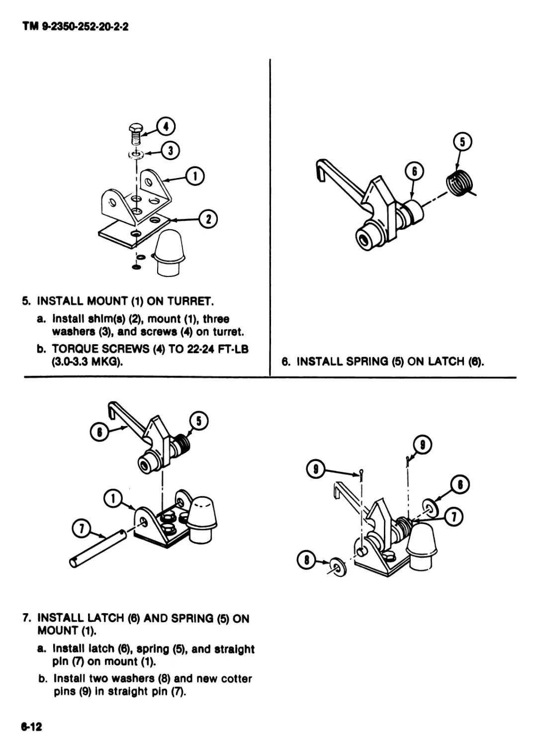
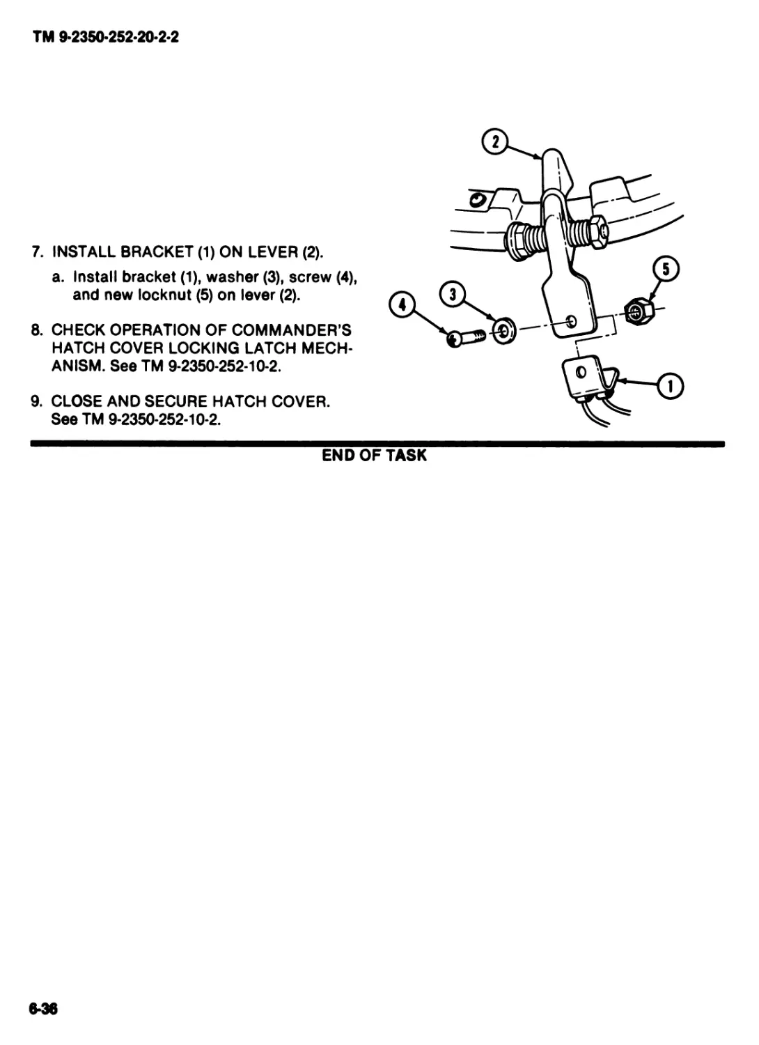
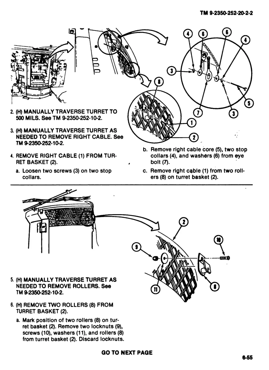
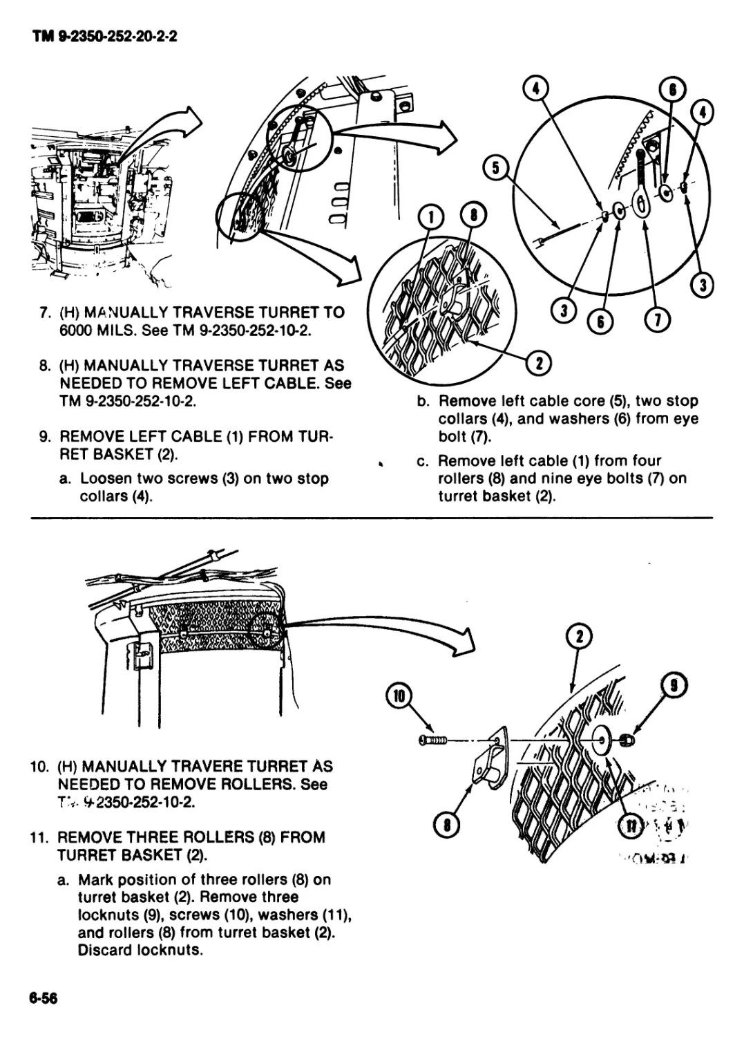
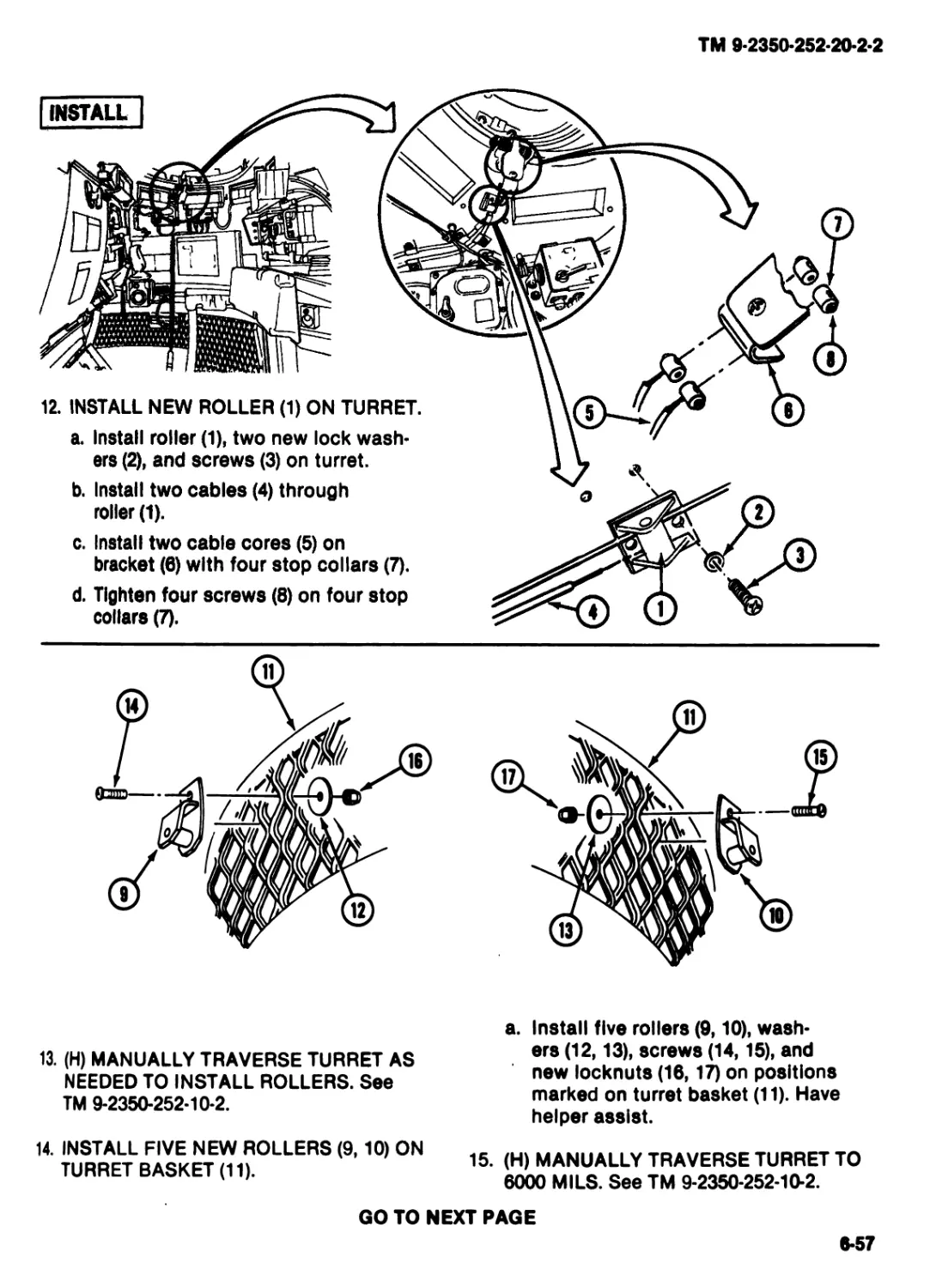
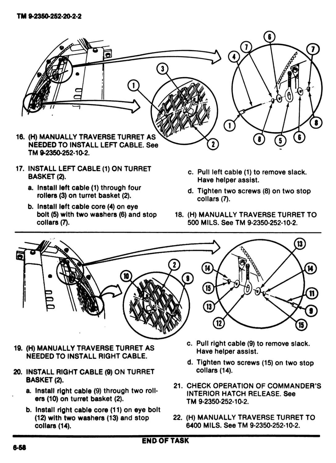
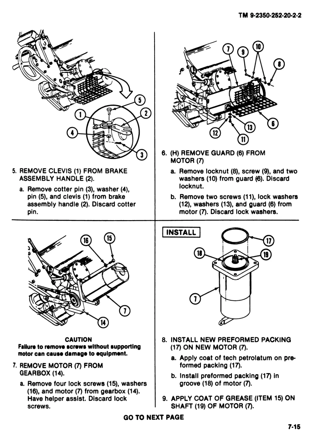
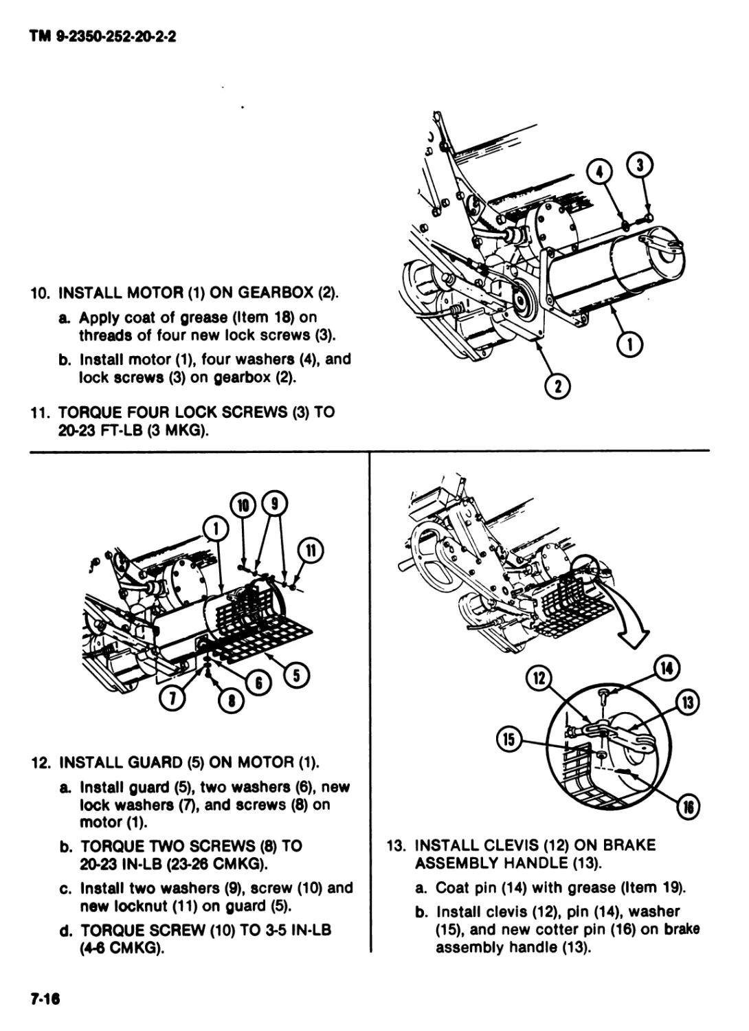
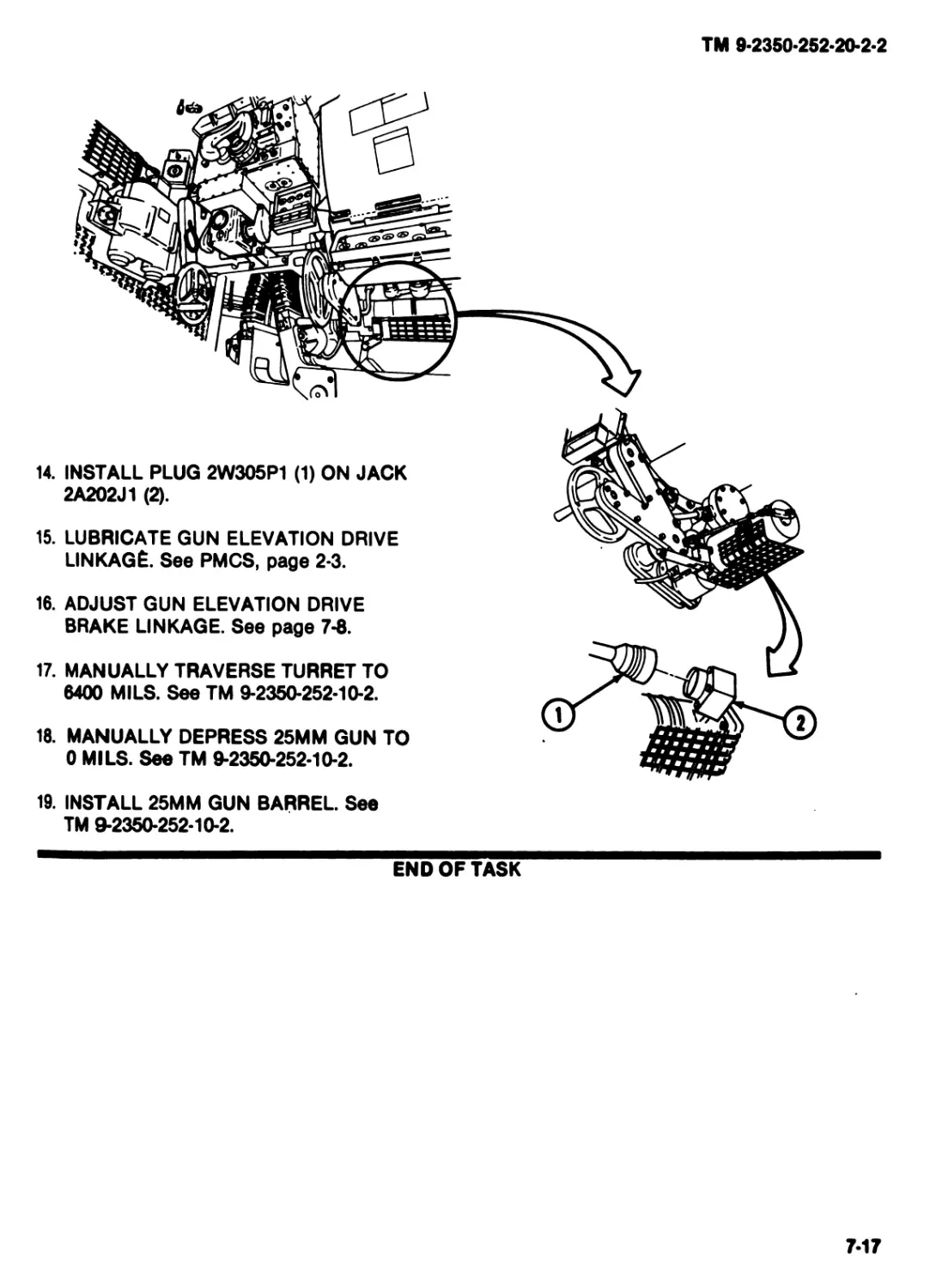
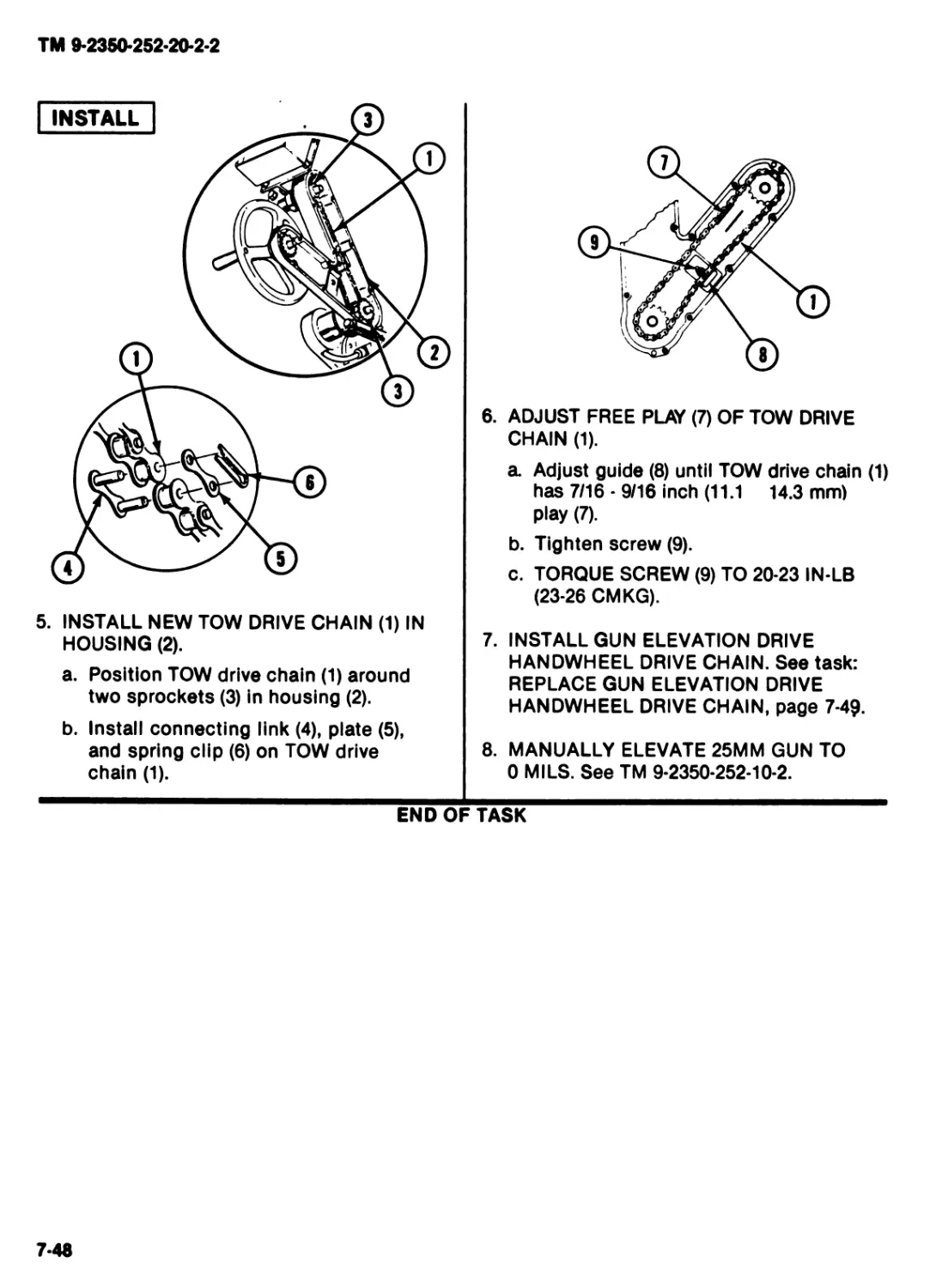
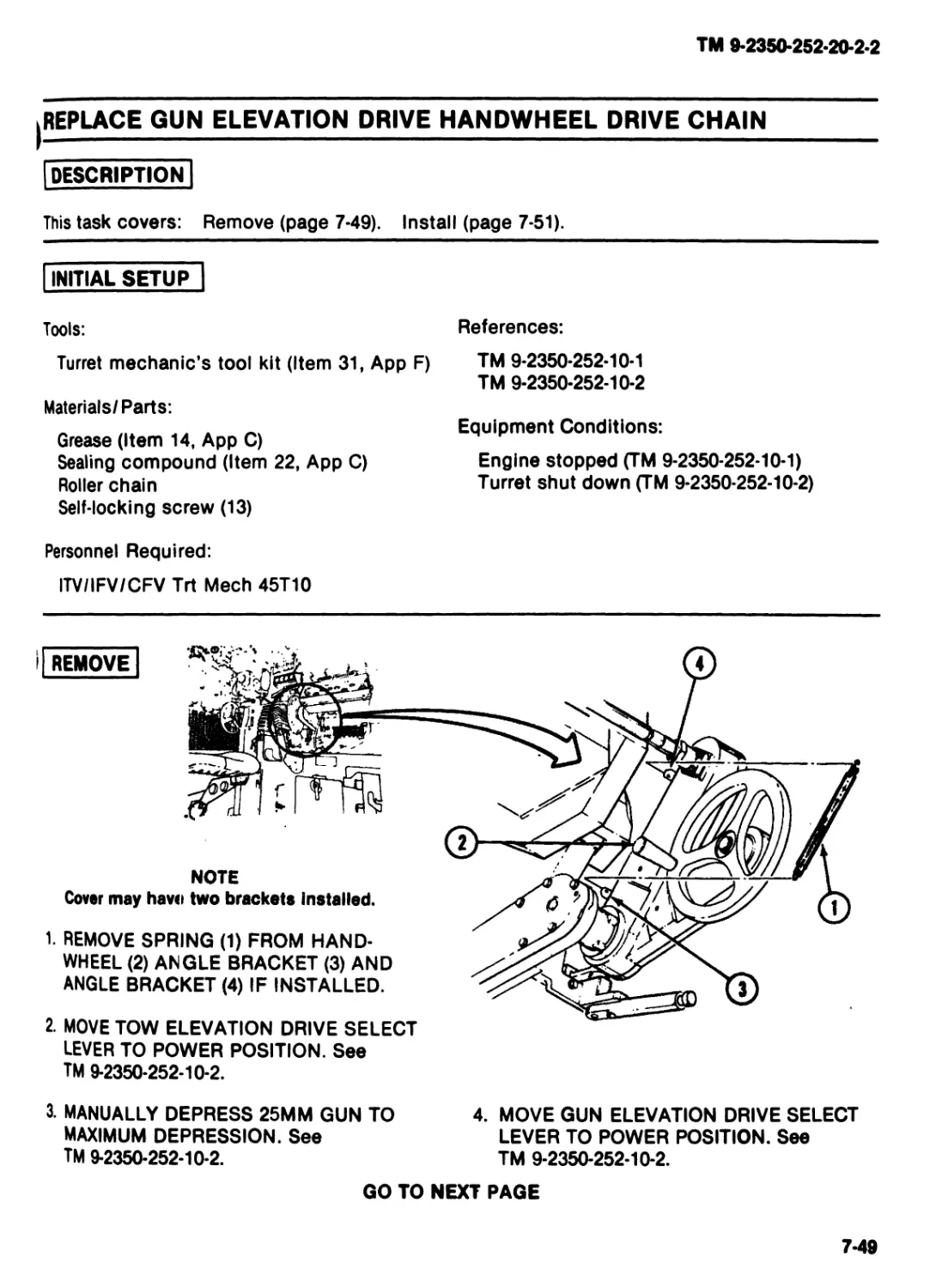
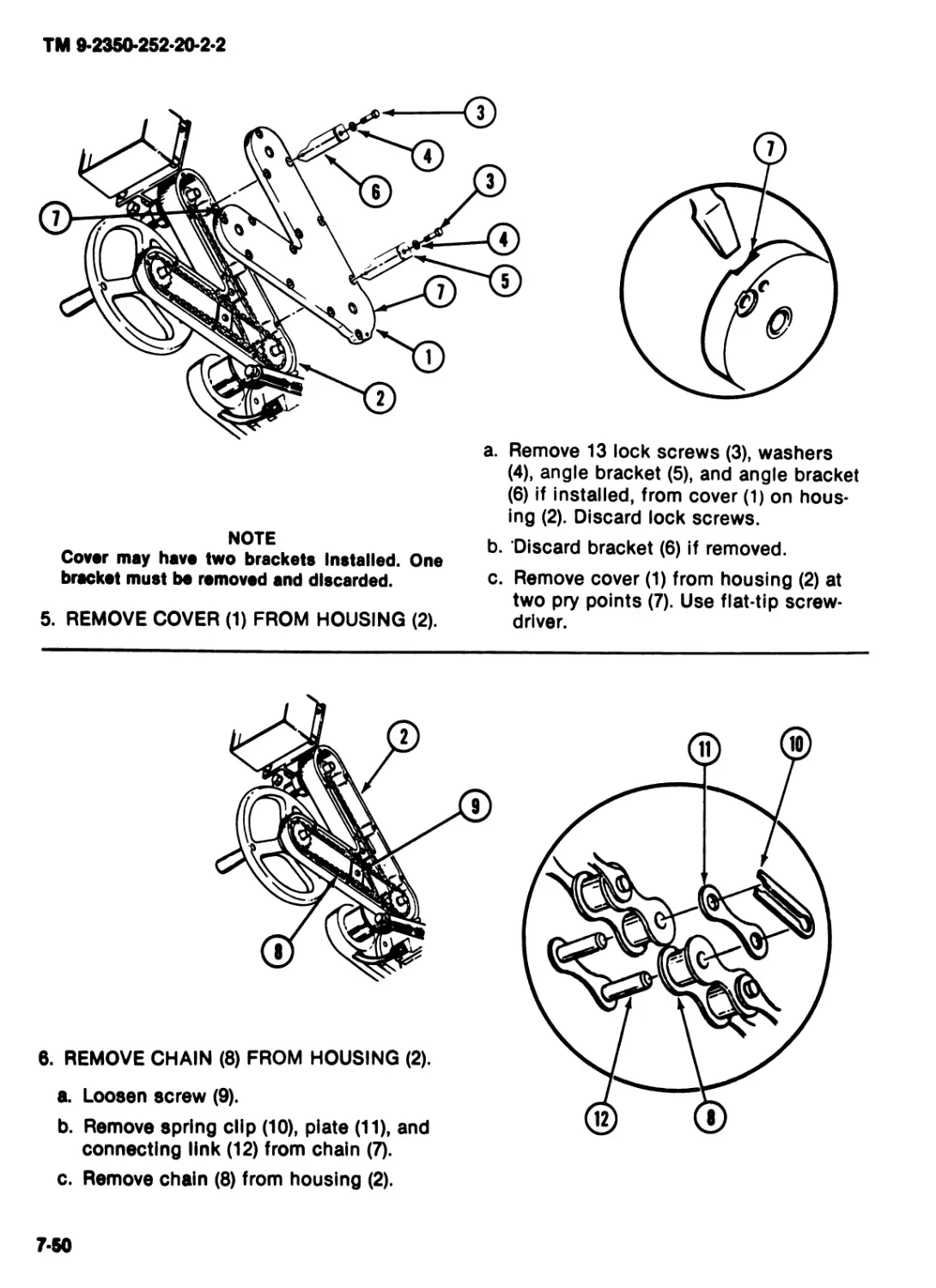
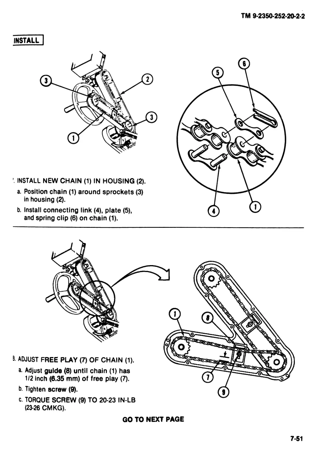
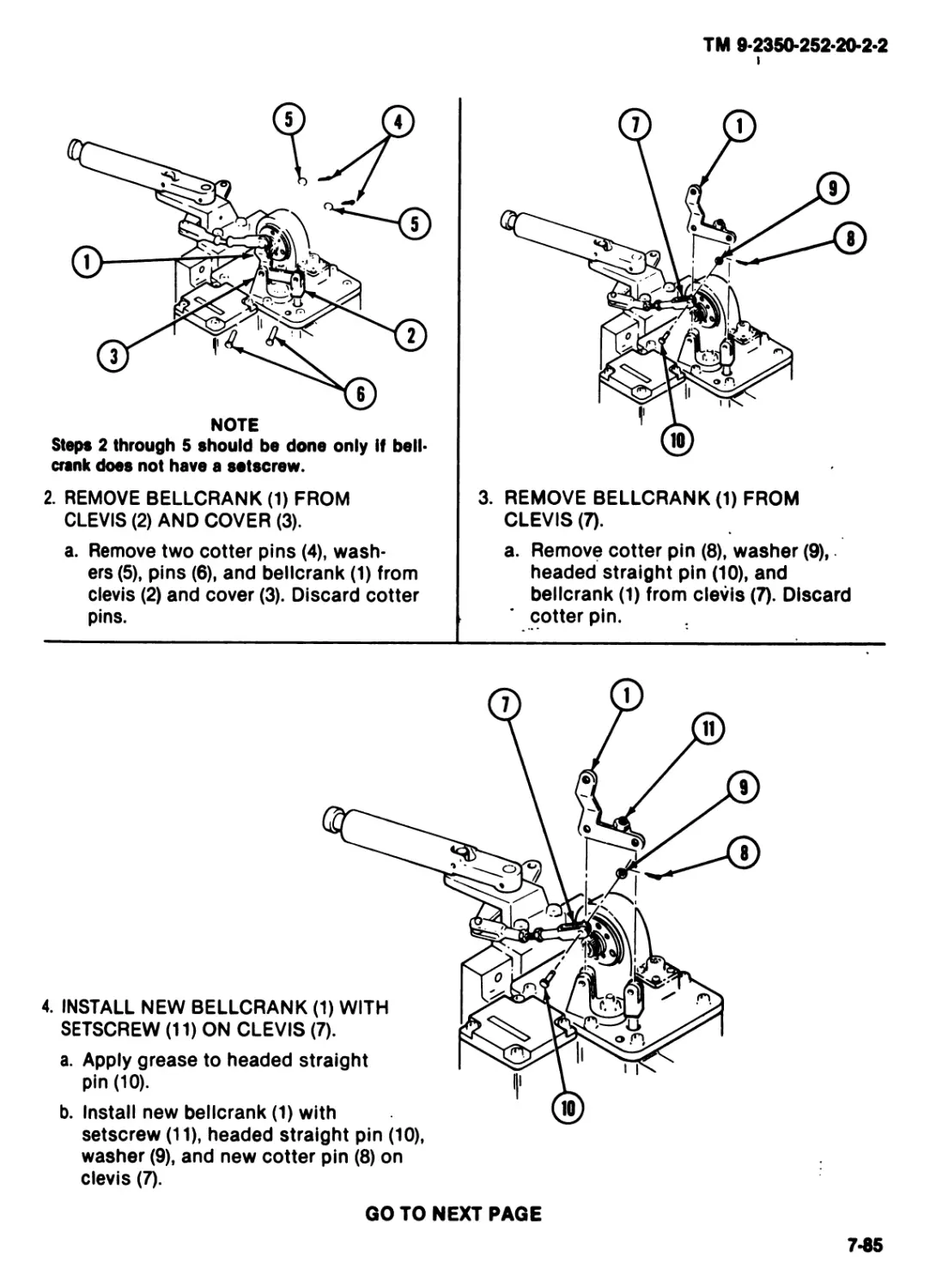
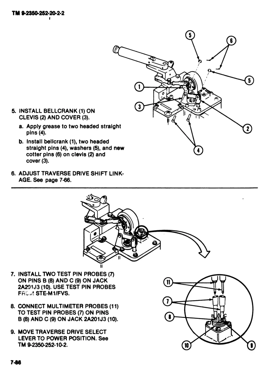
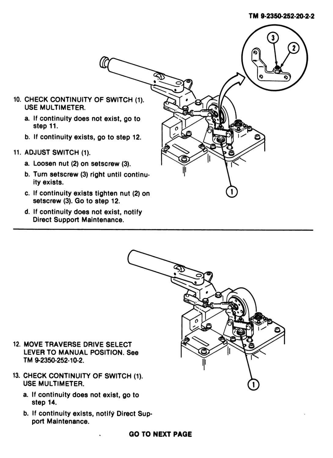
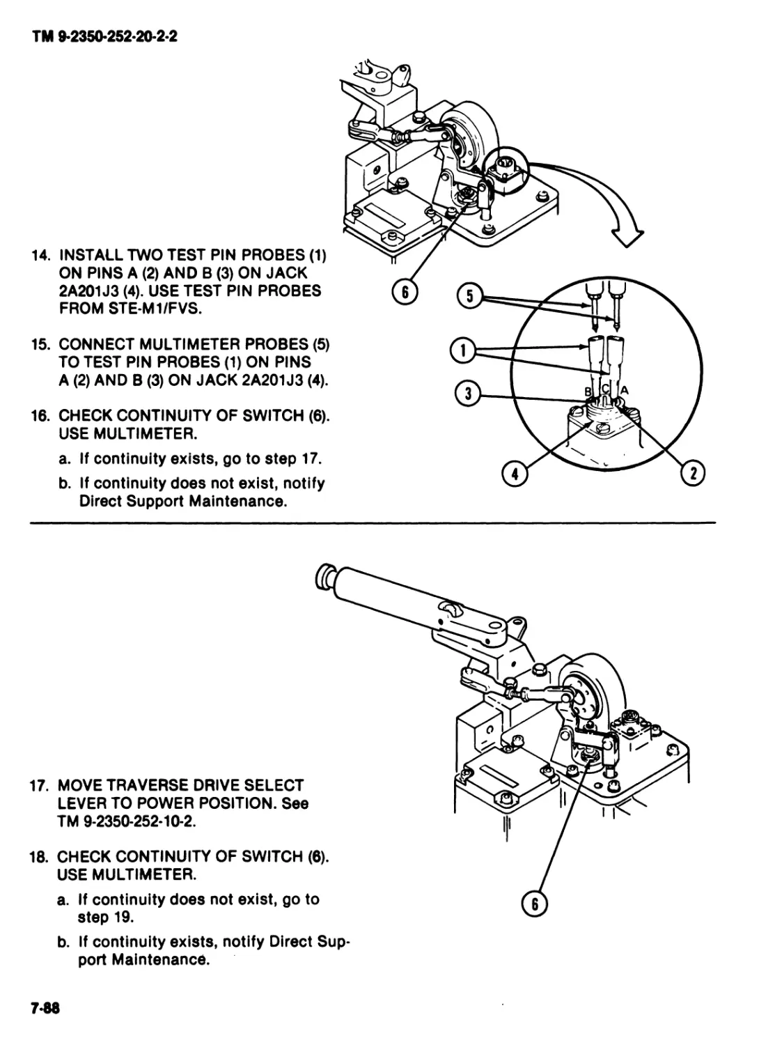
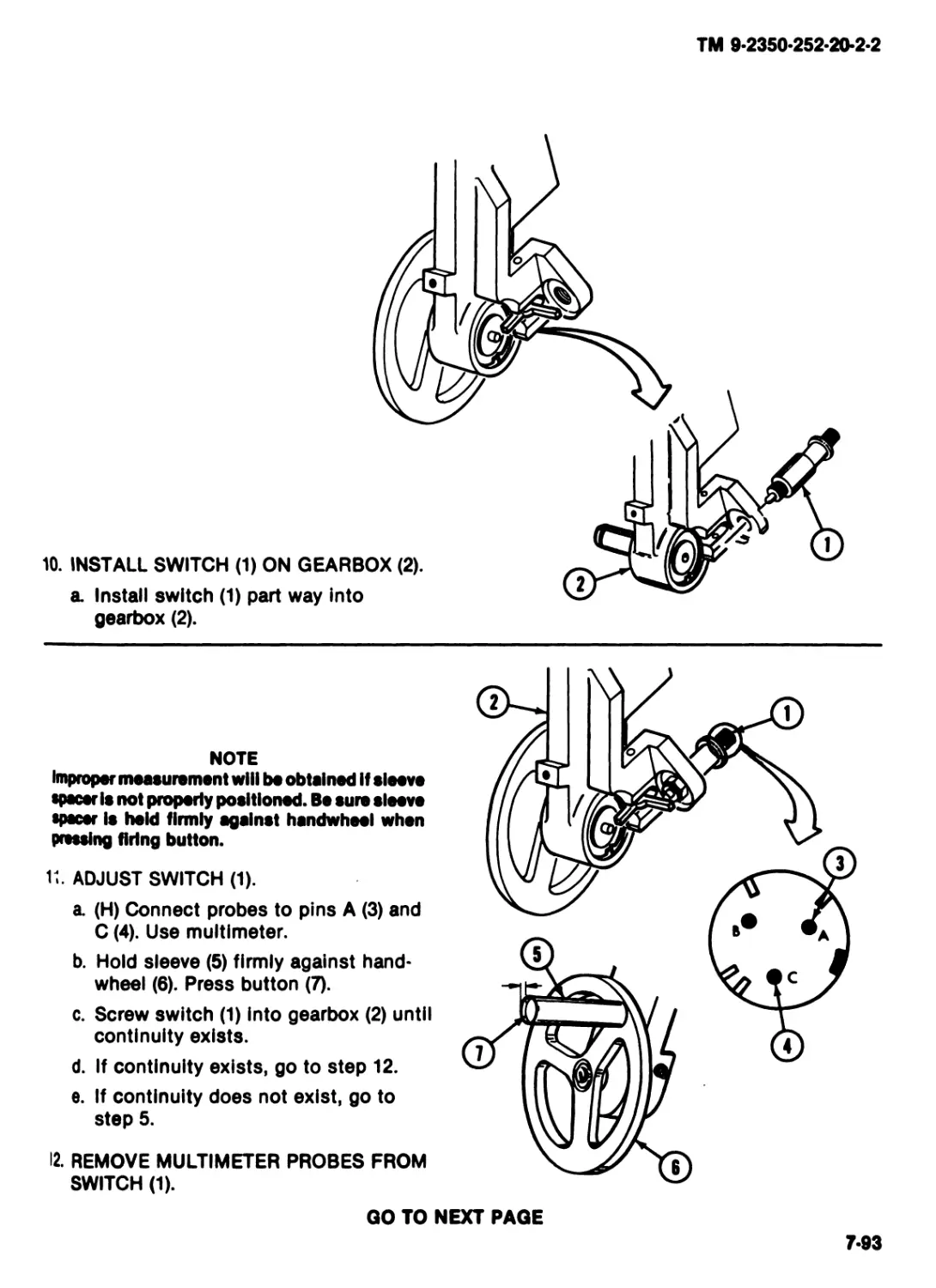
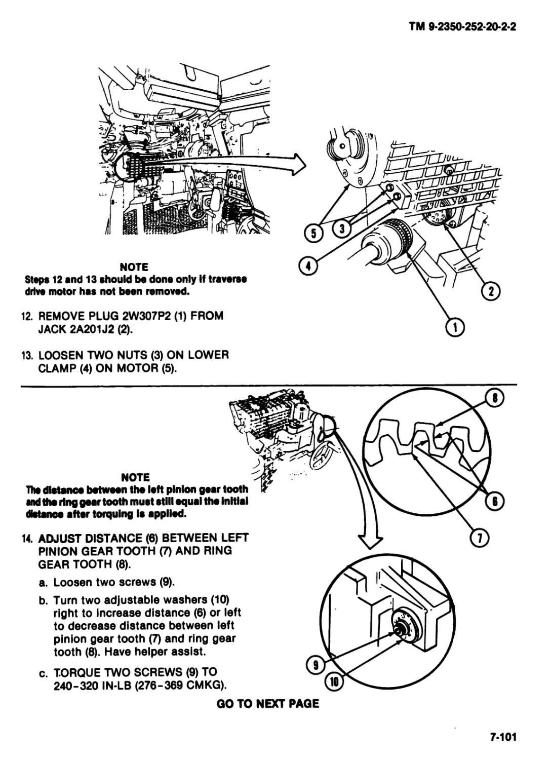
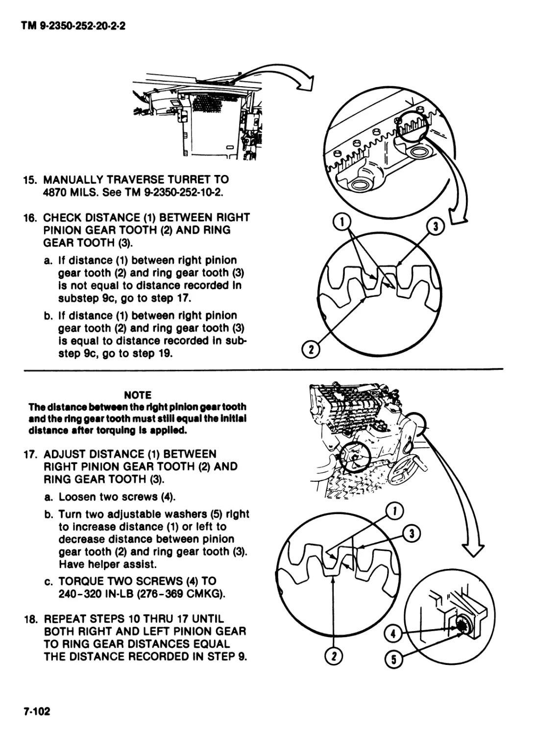
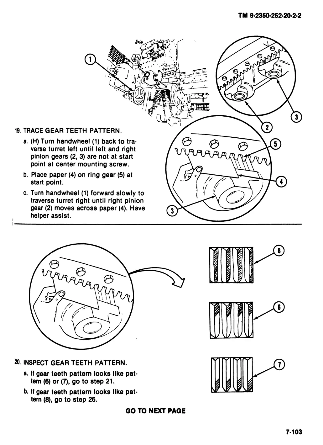
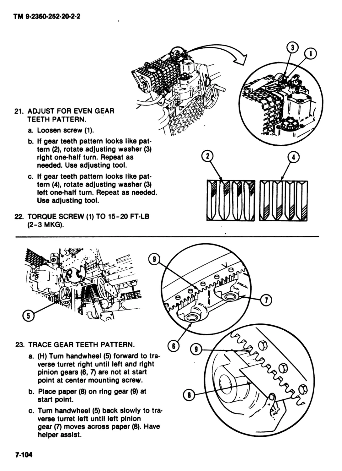
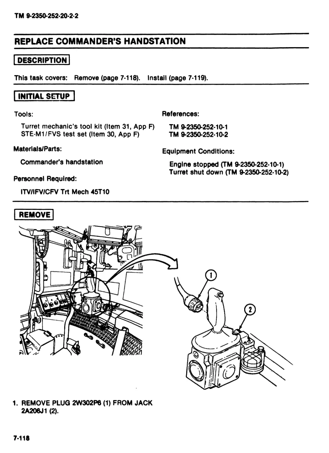
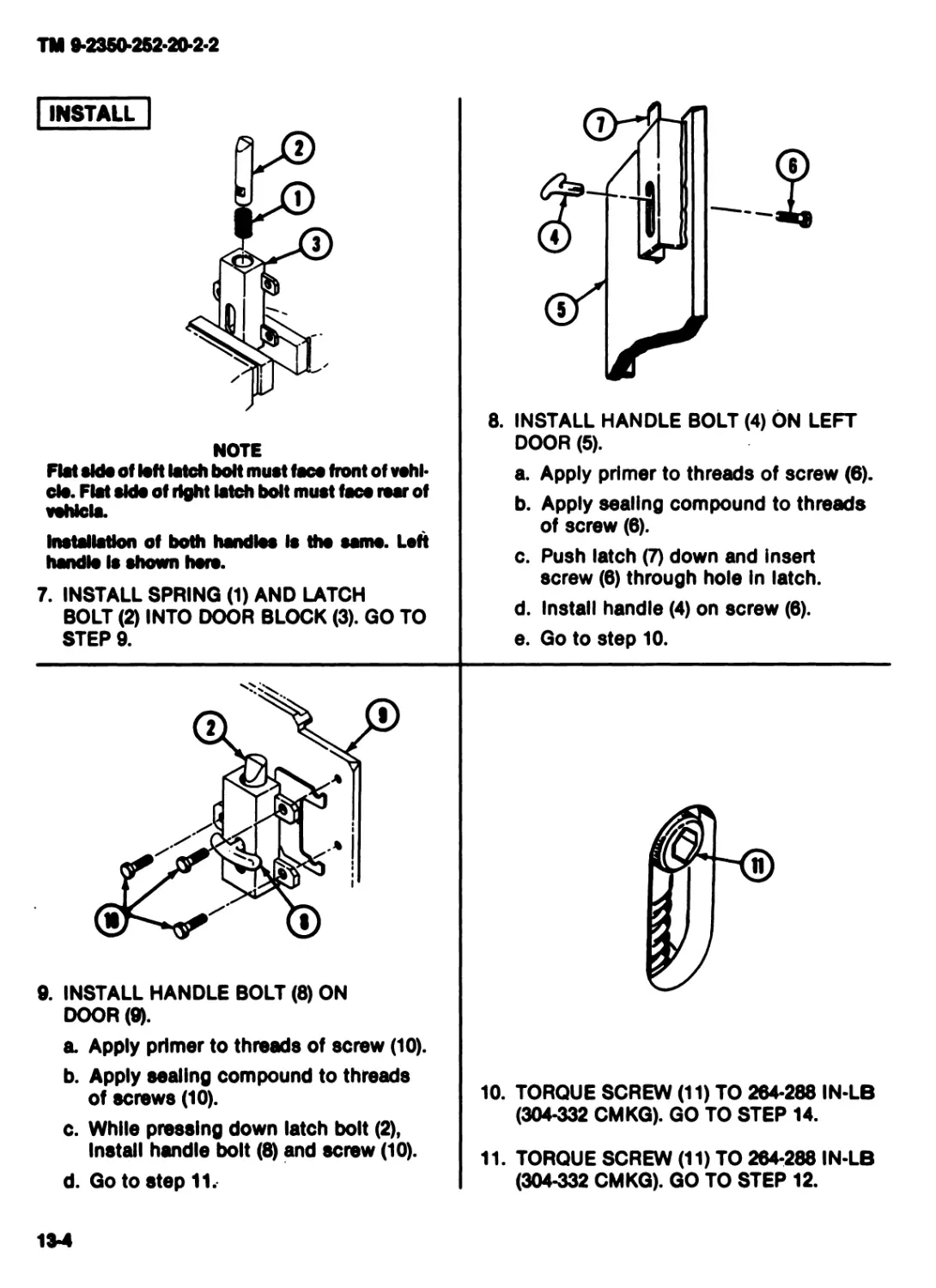
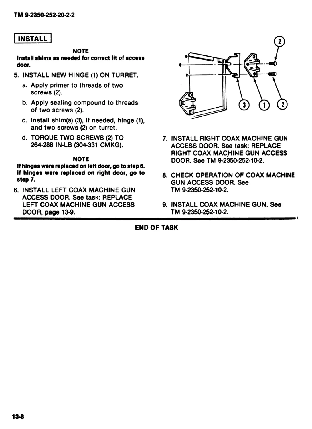
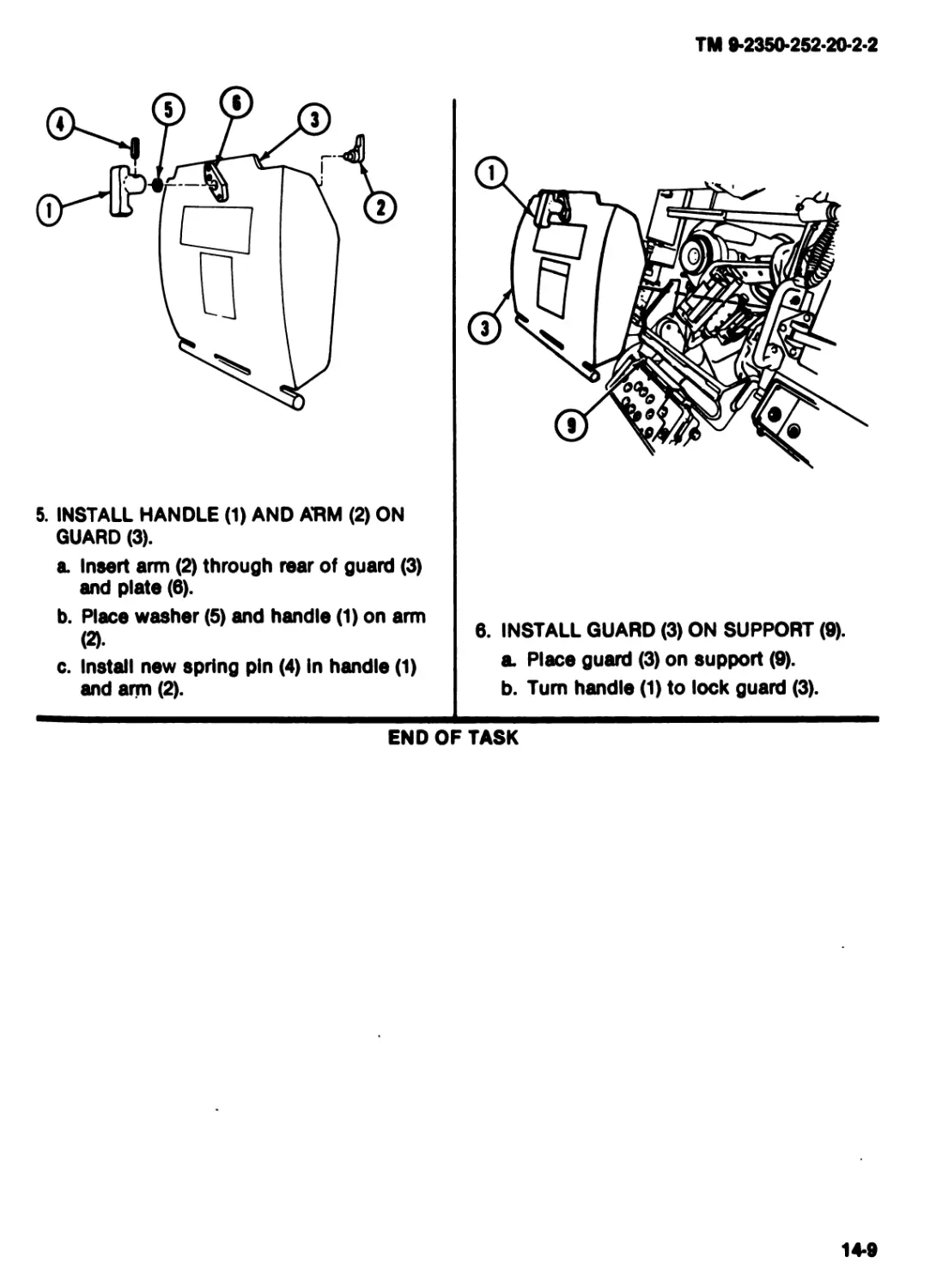
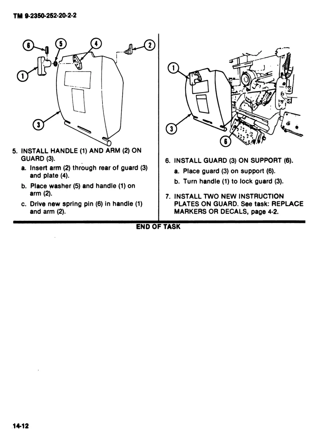
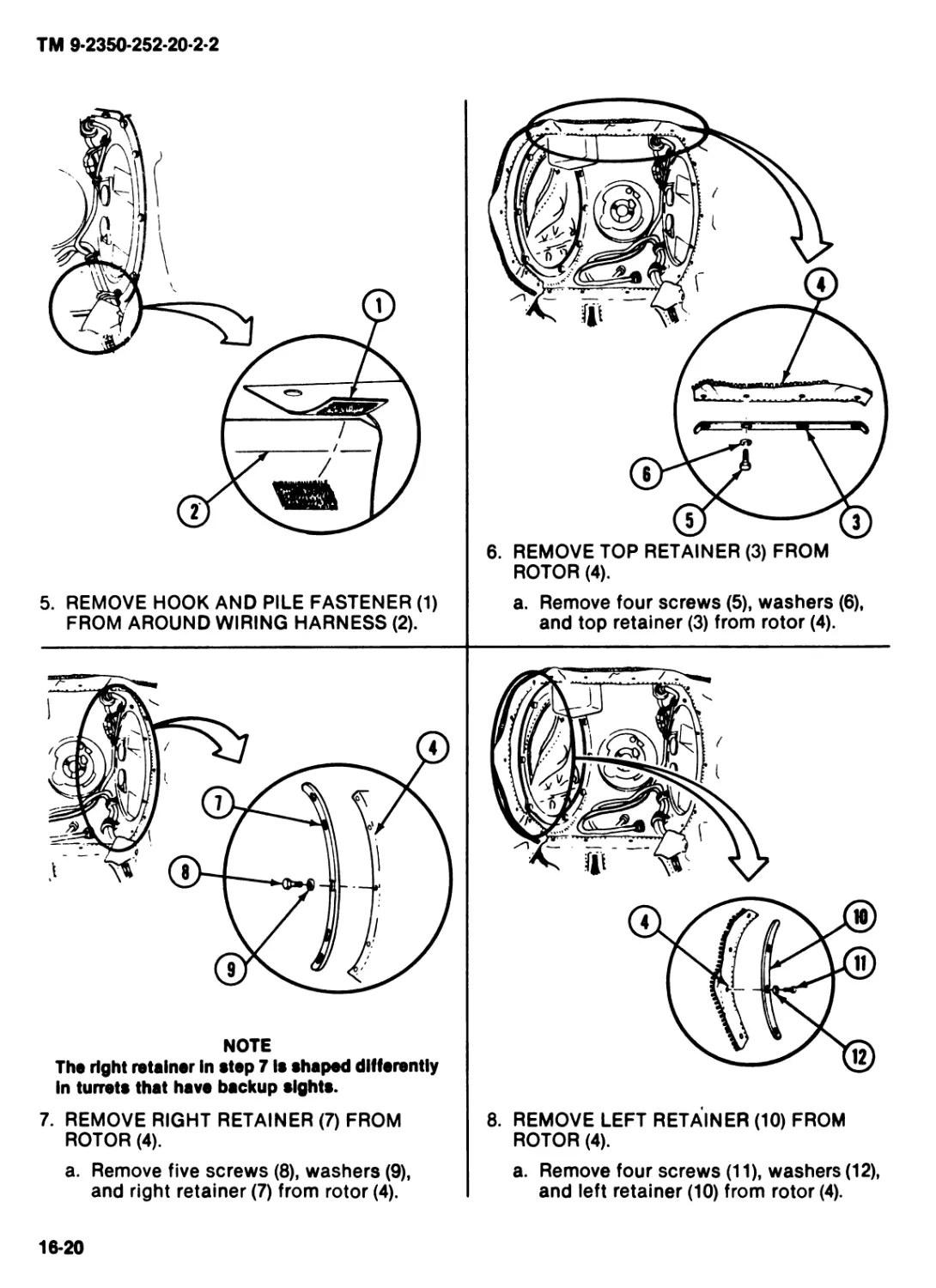
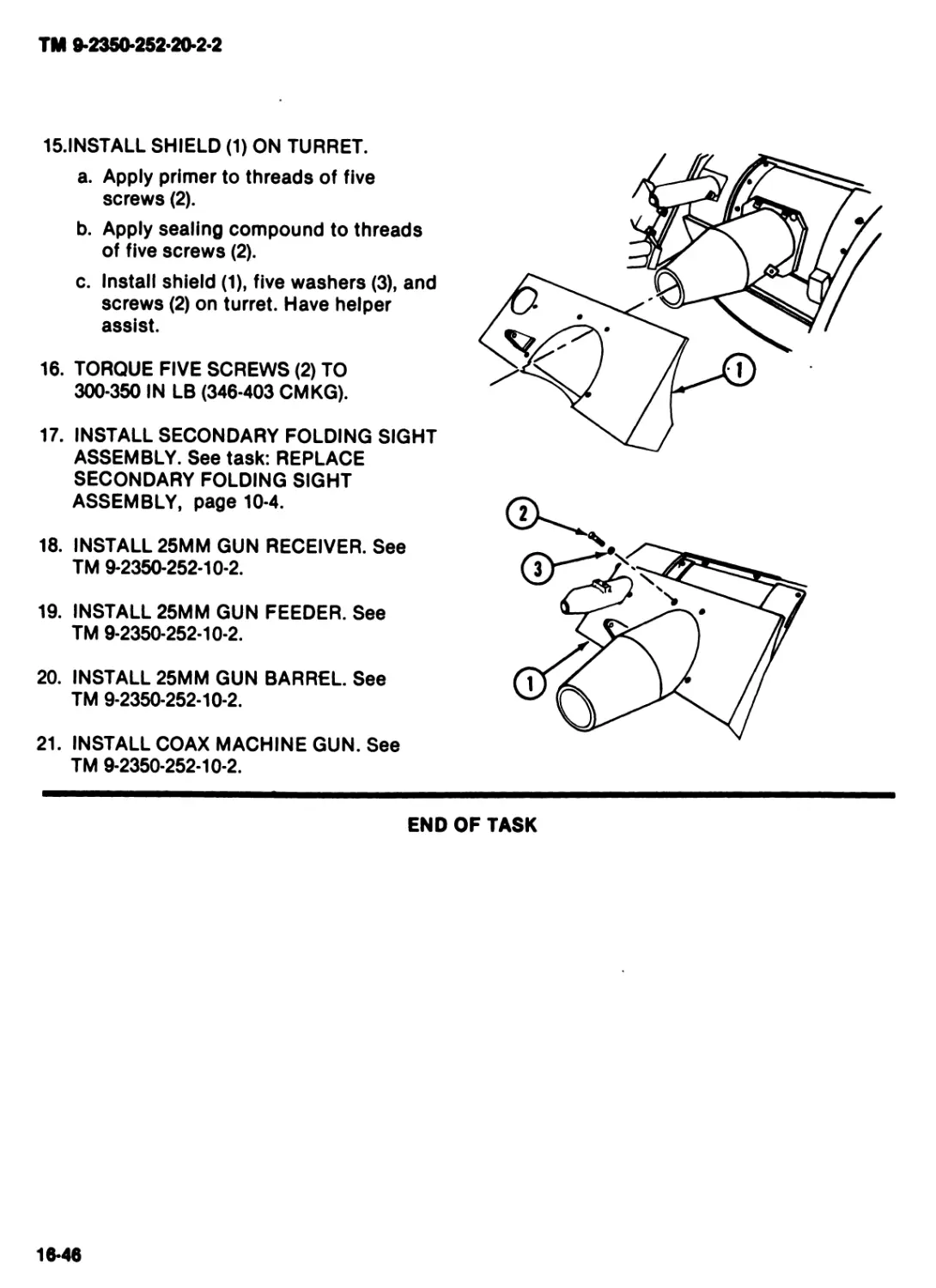
TM 9-2350-252-20-2-2
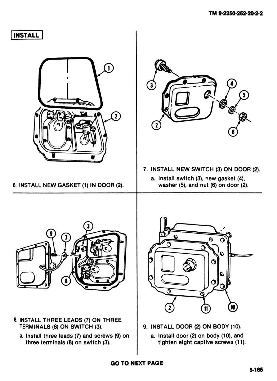
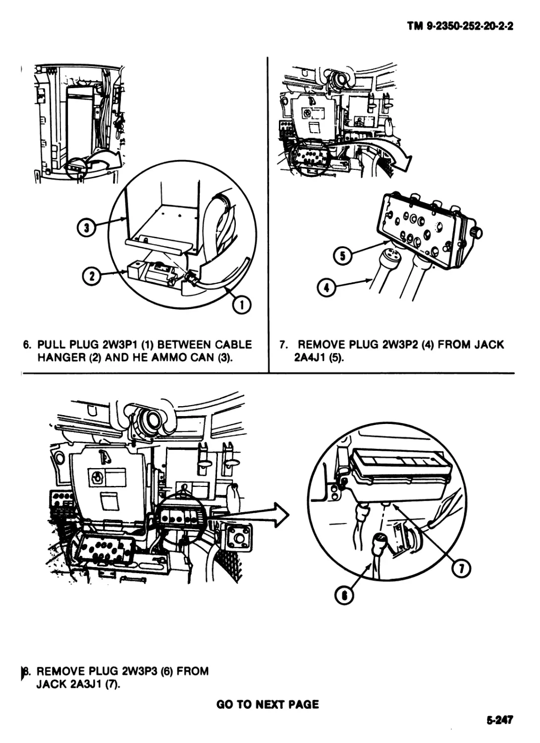
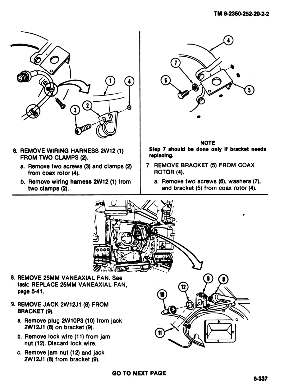
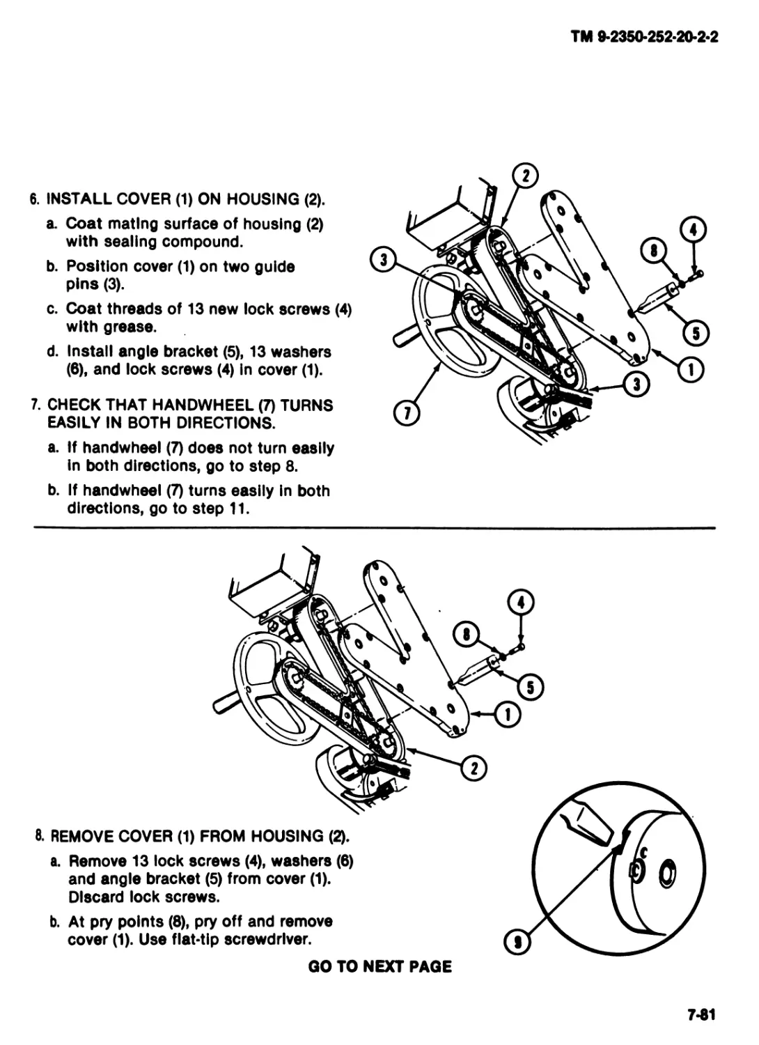
TECHNICAL MANUAL
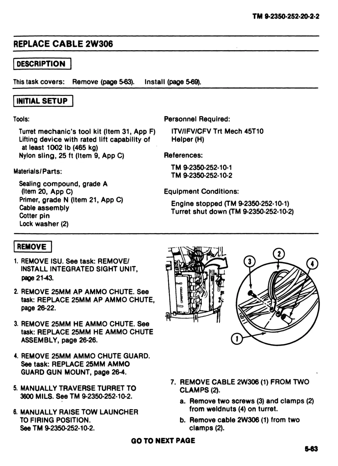
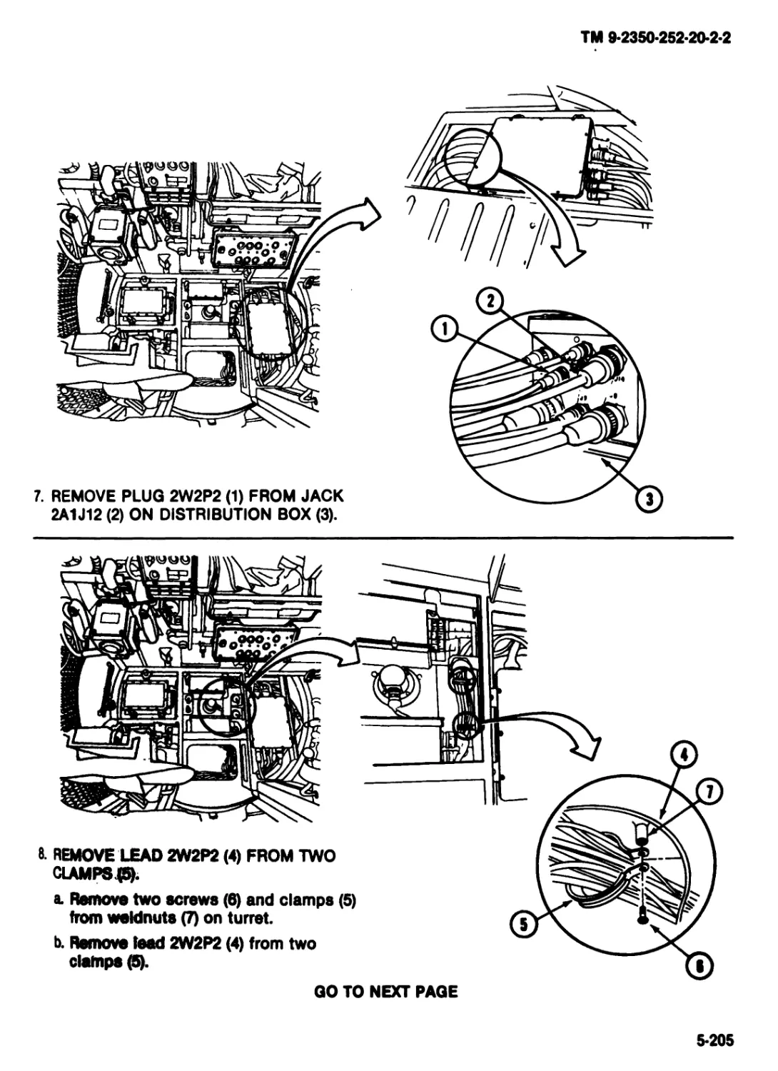
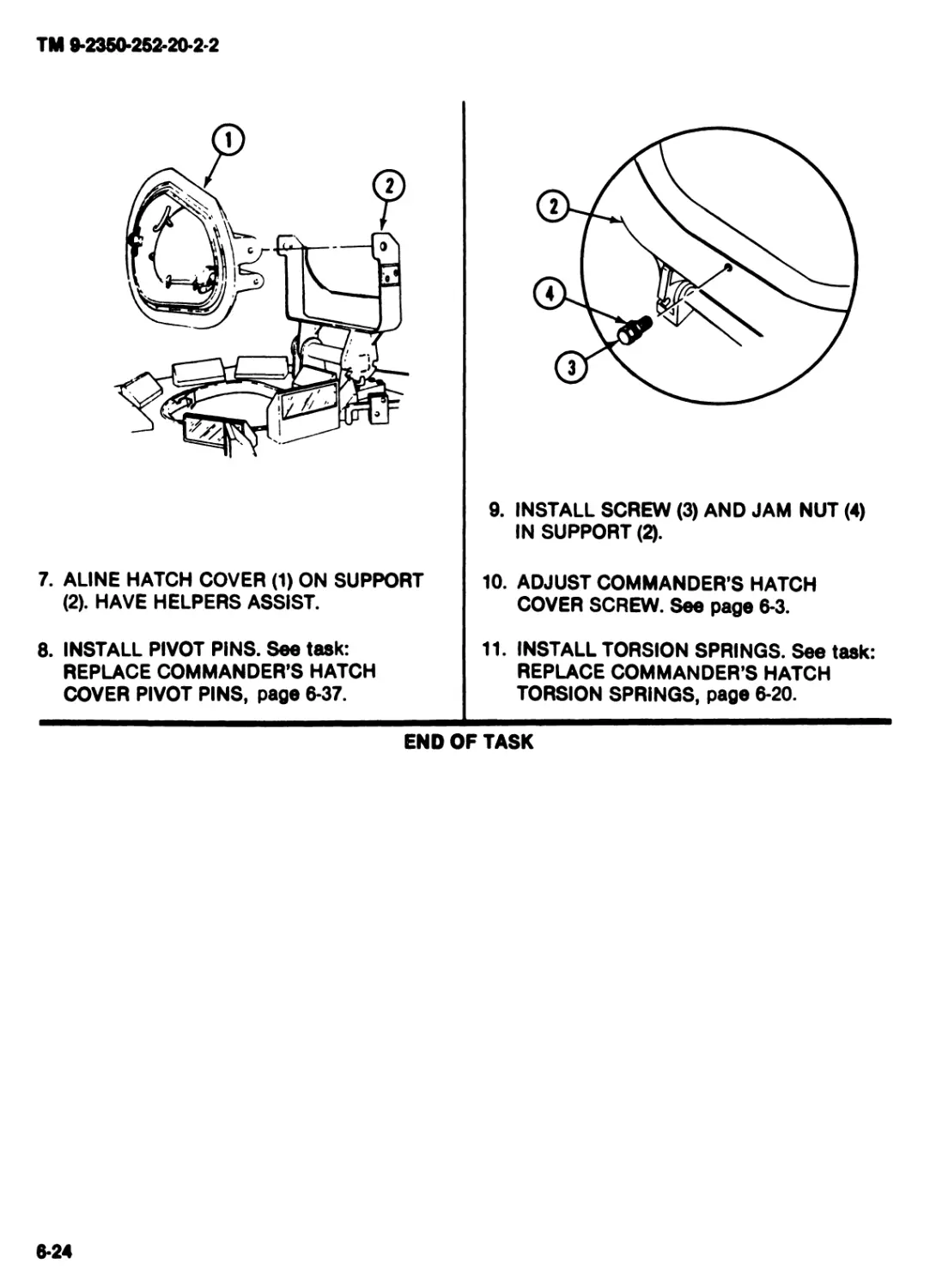
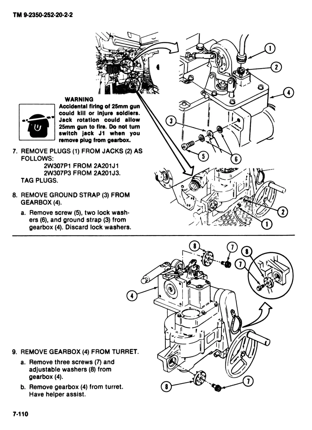
ORGANIZATIONAL MAINTENANCE
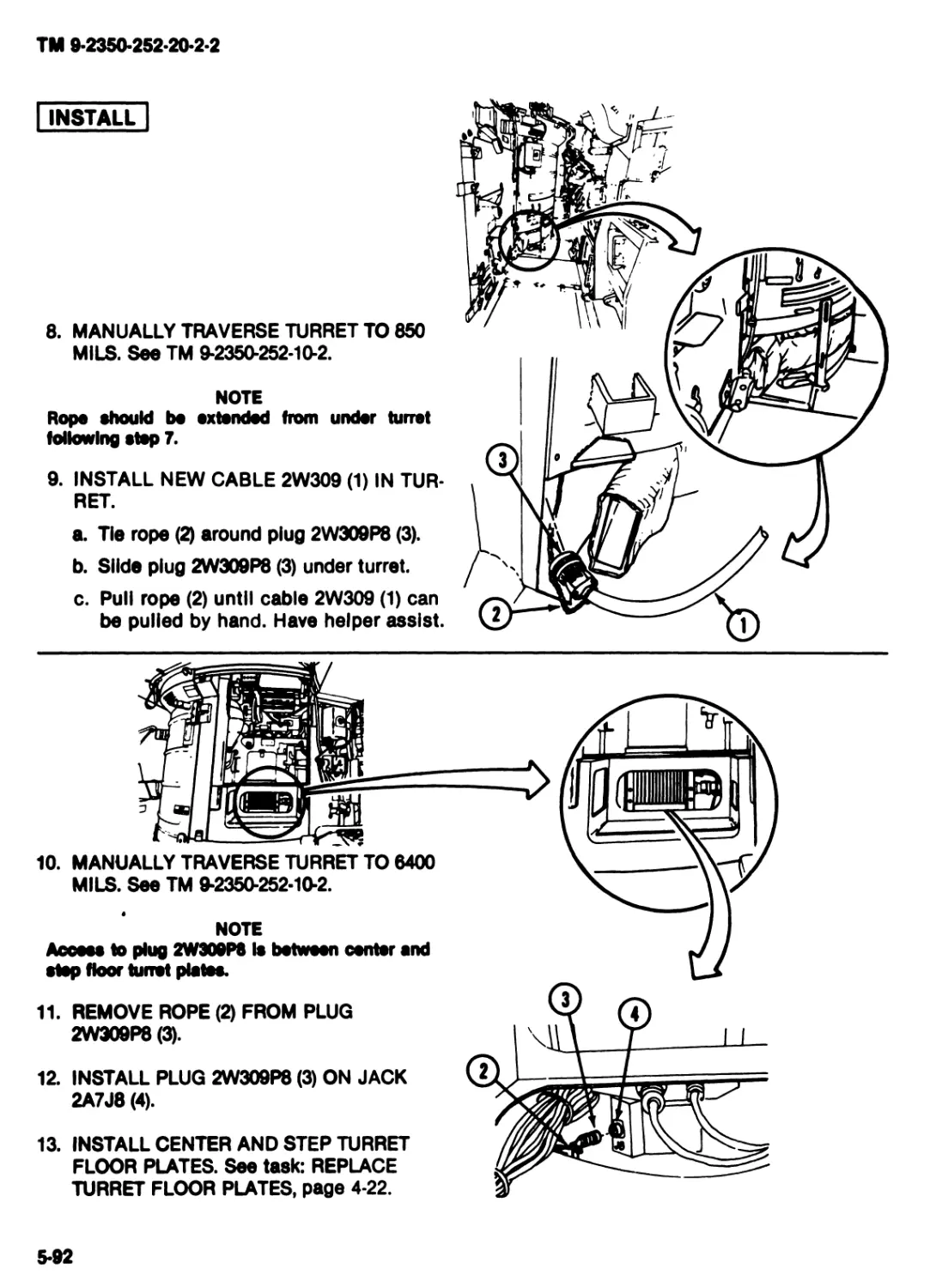
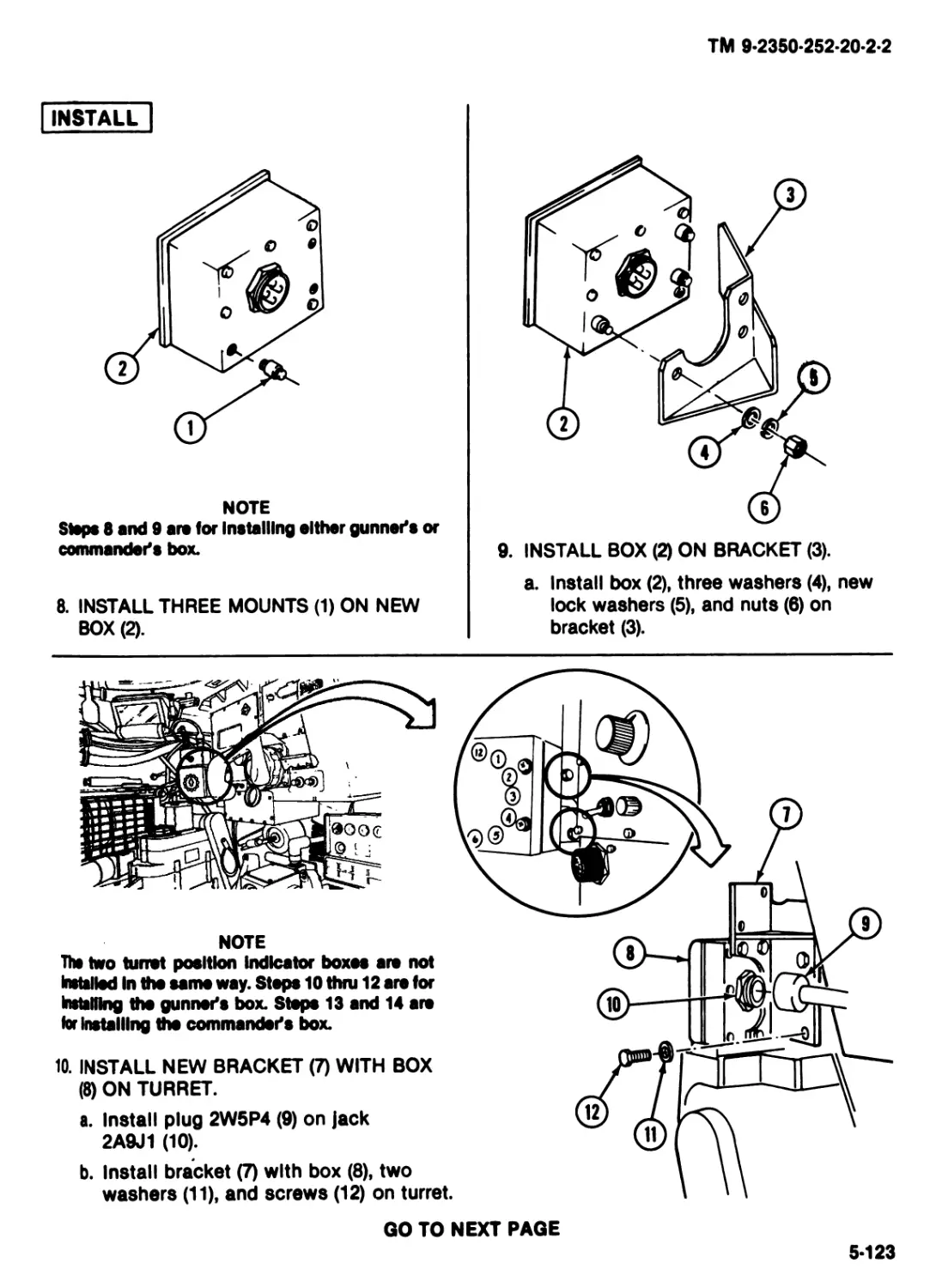
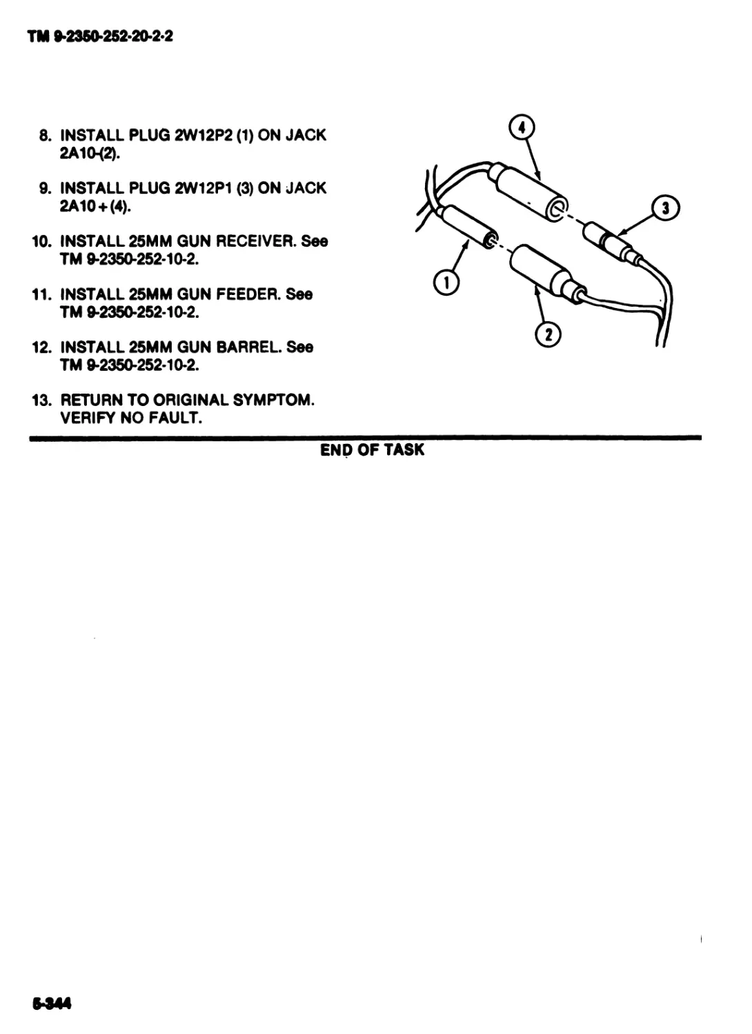
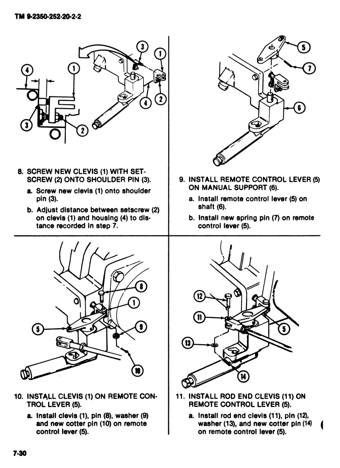
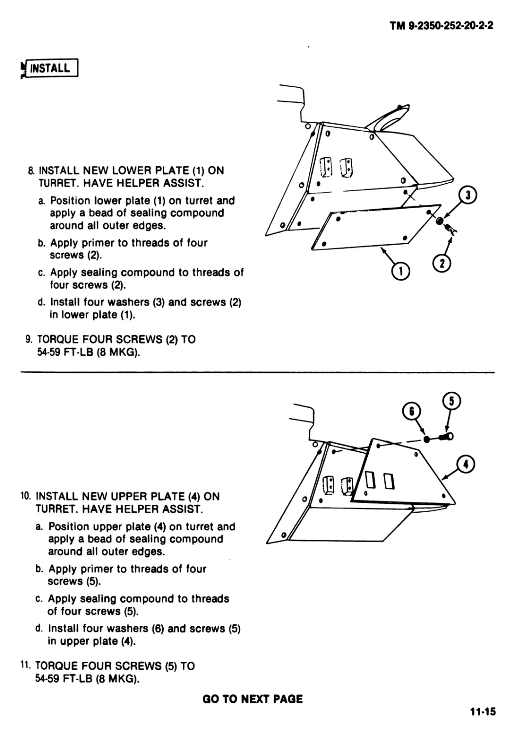
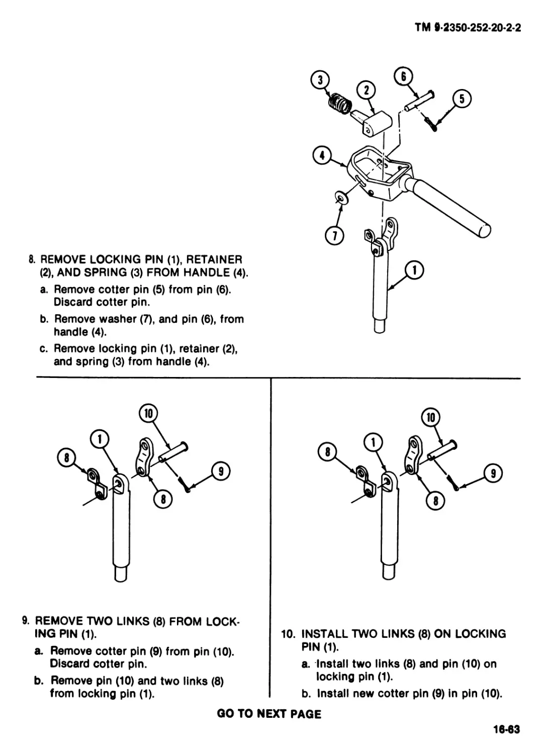
MAINTENANCE OF
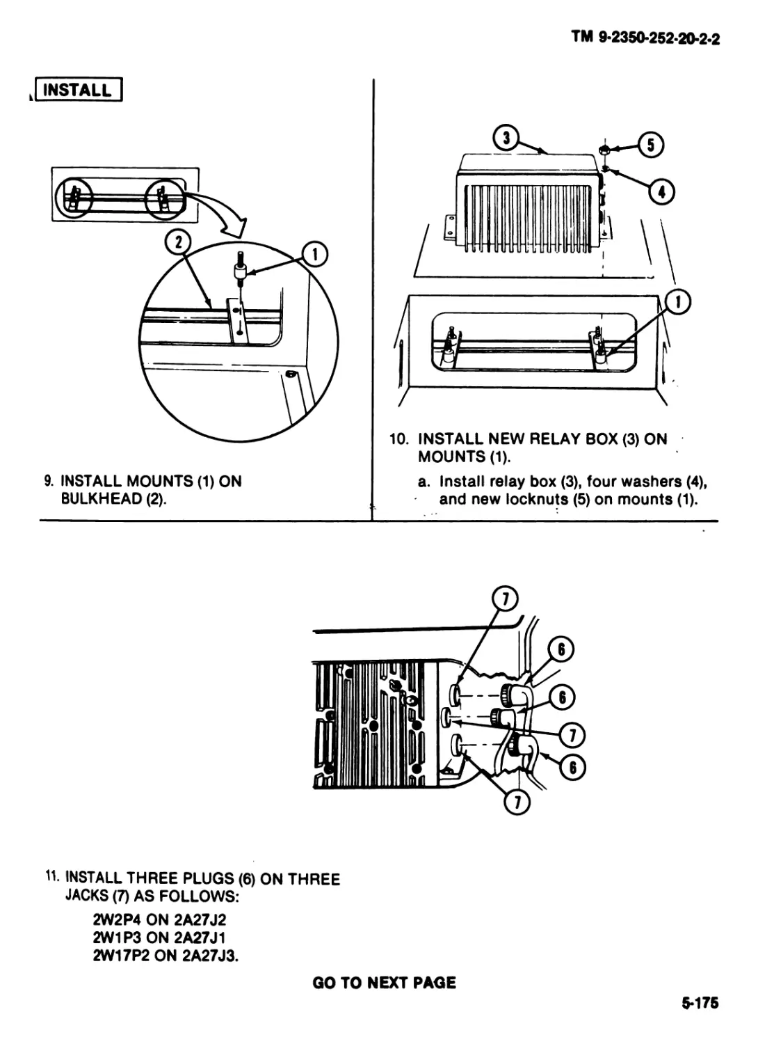
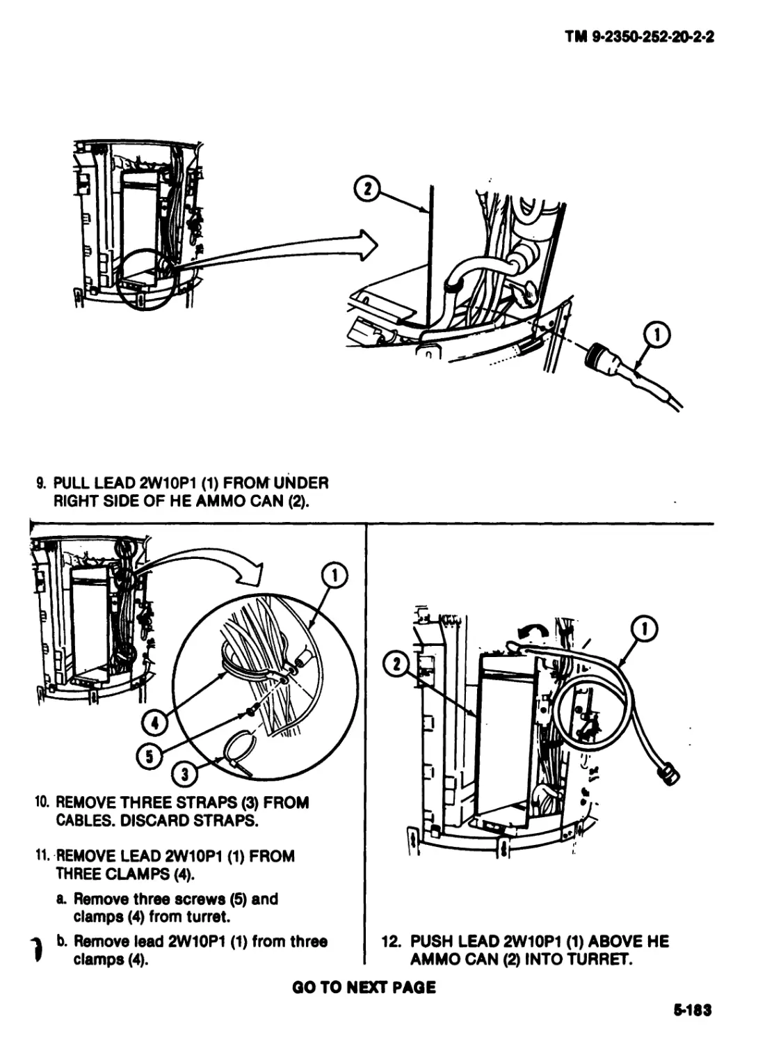
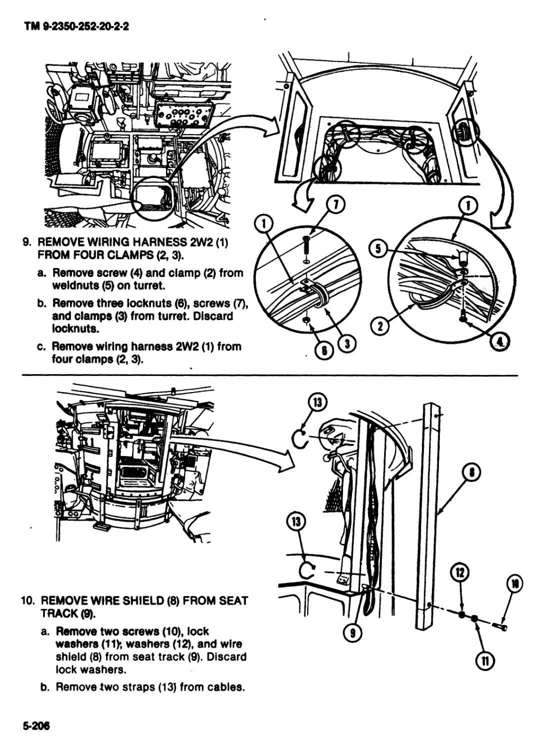
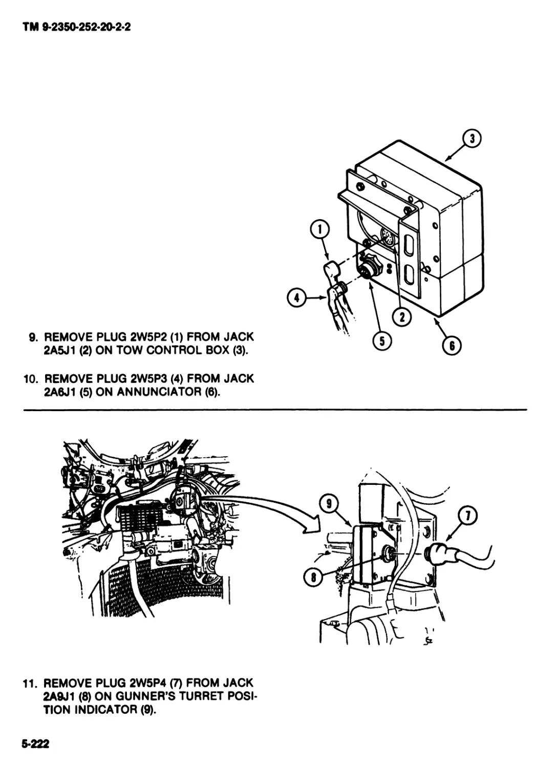
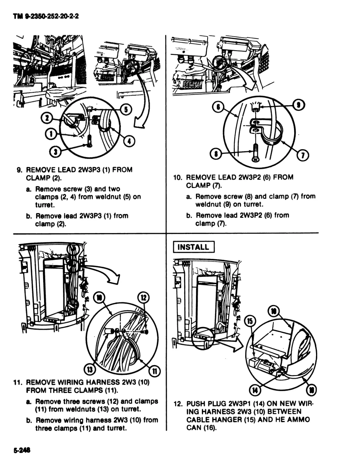
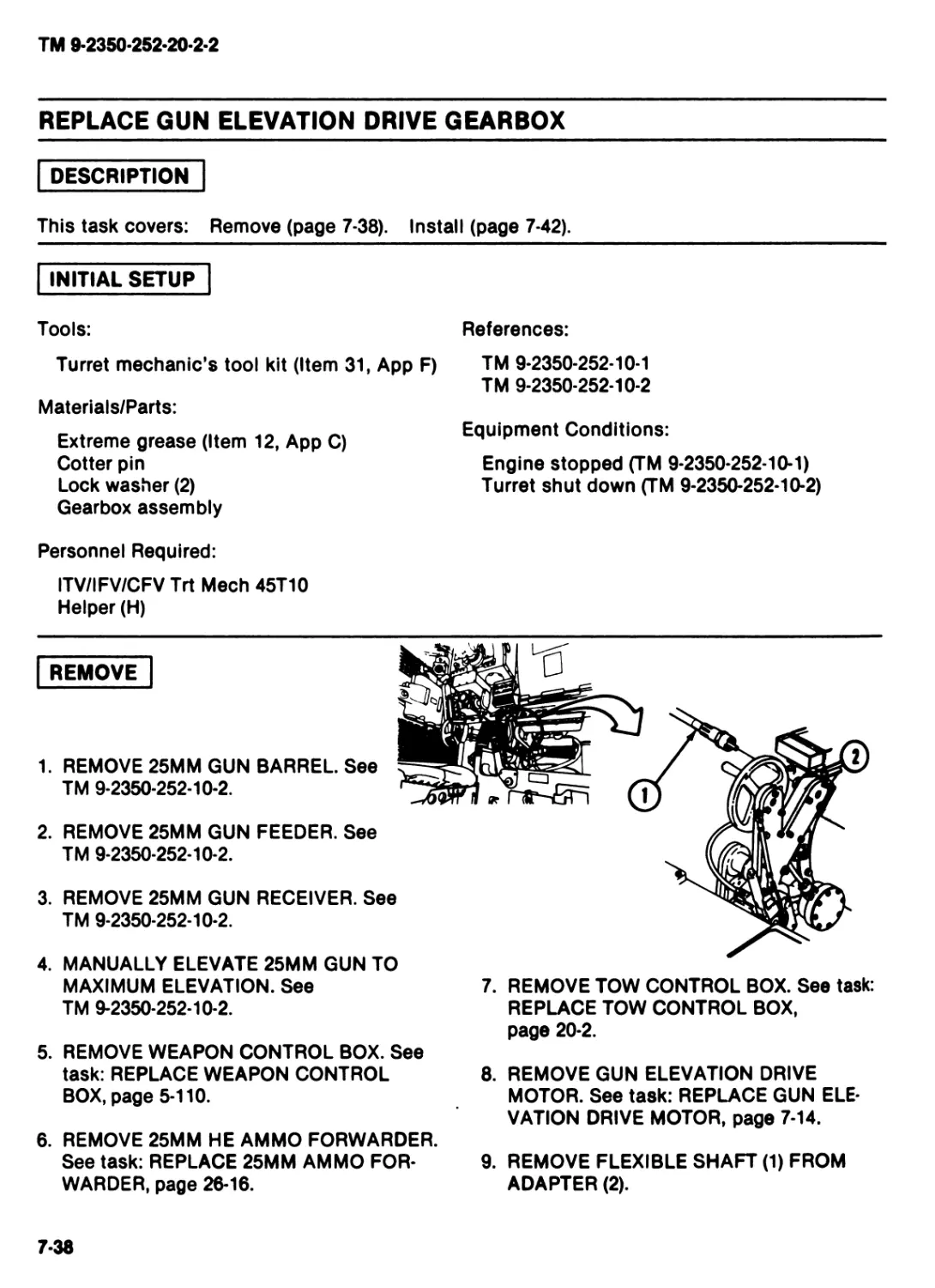
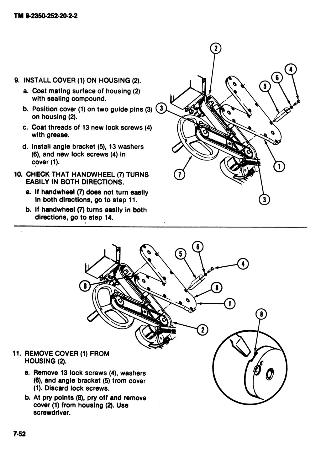
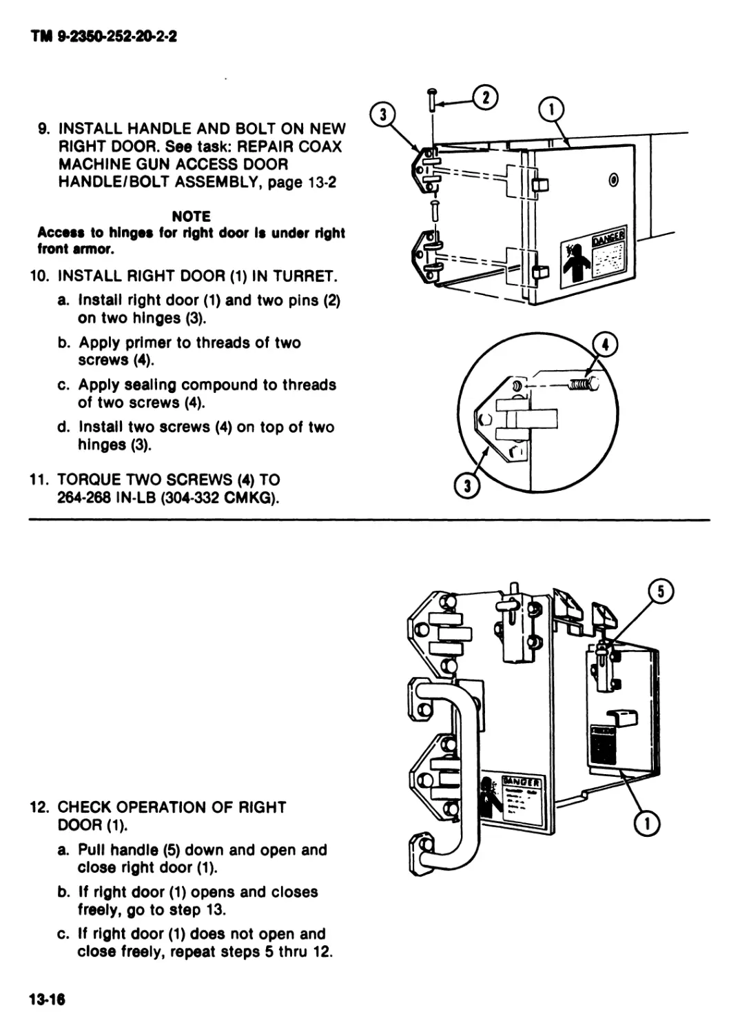
TURRET
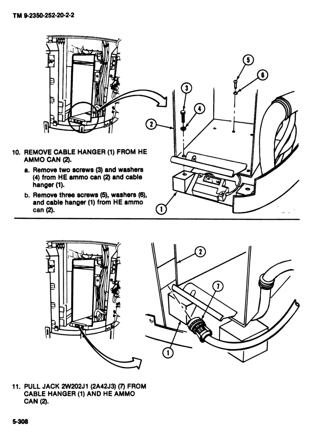
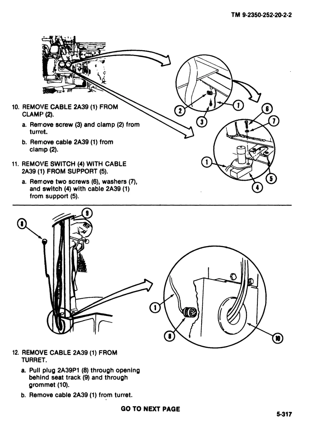
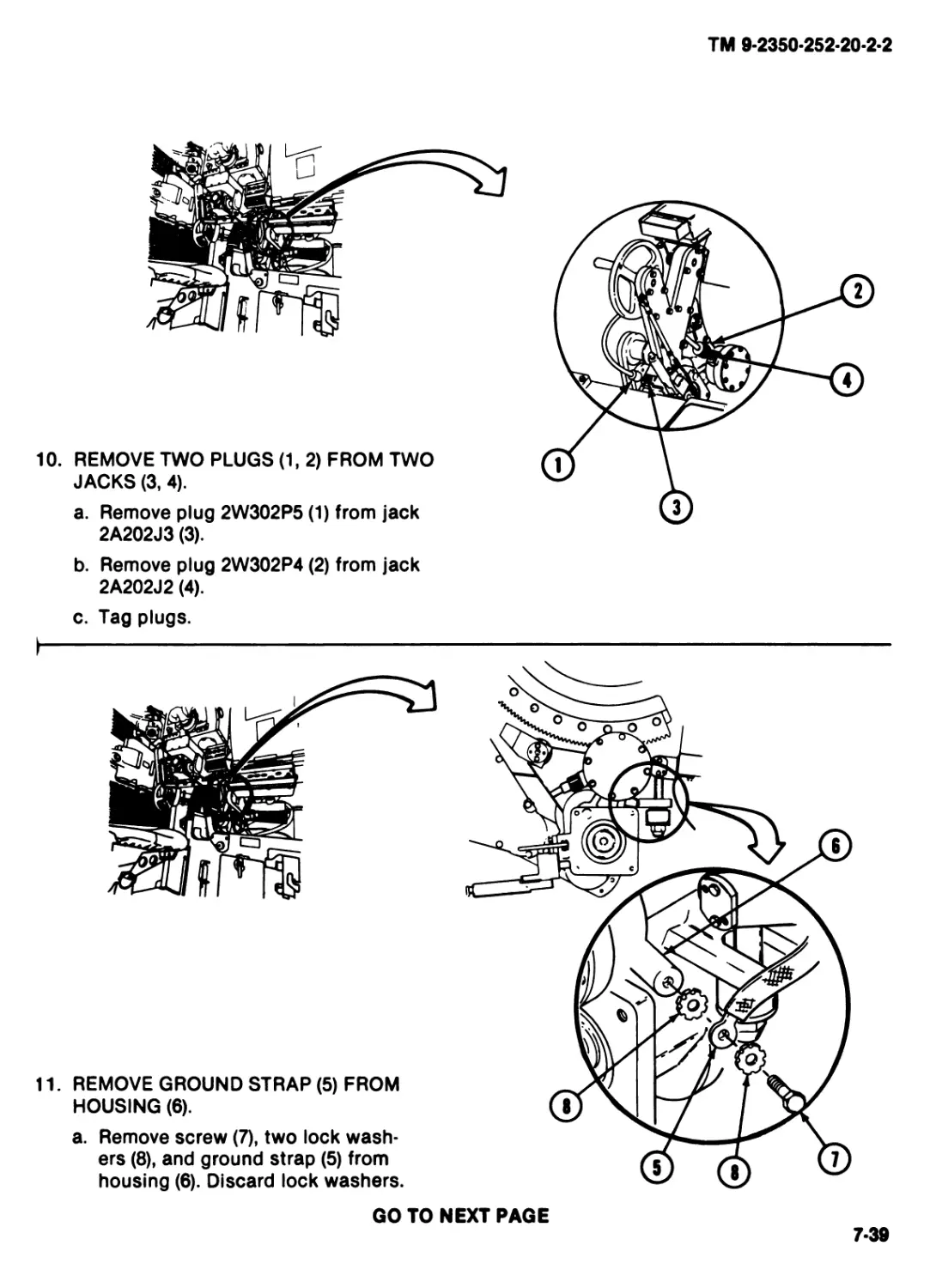
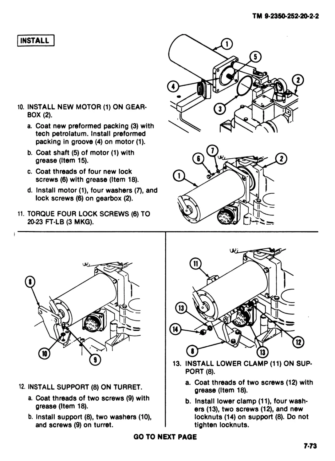
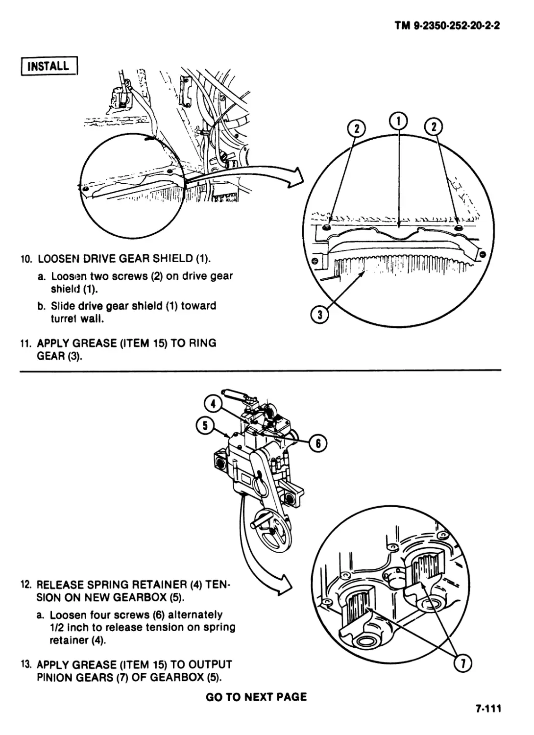
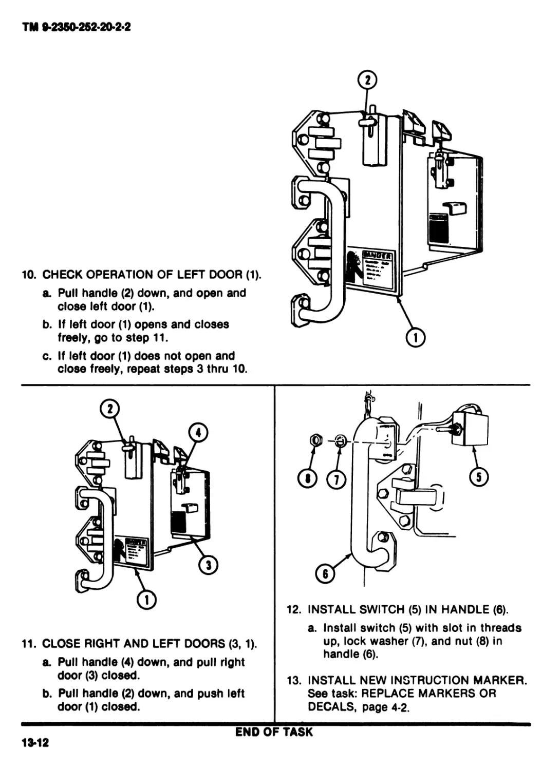
FIGHTING VEHICLE, INFANTRY, М2
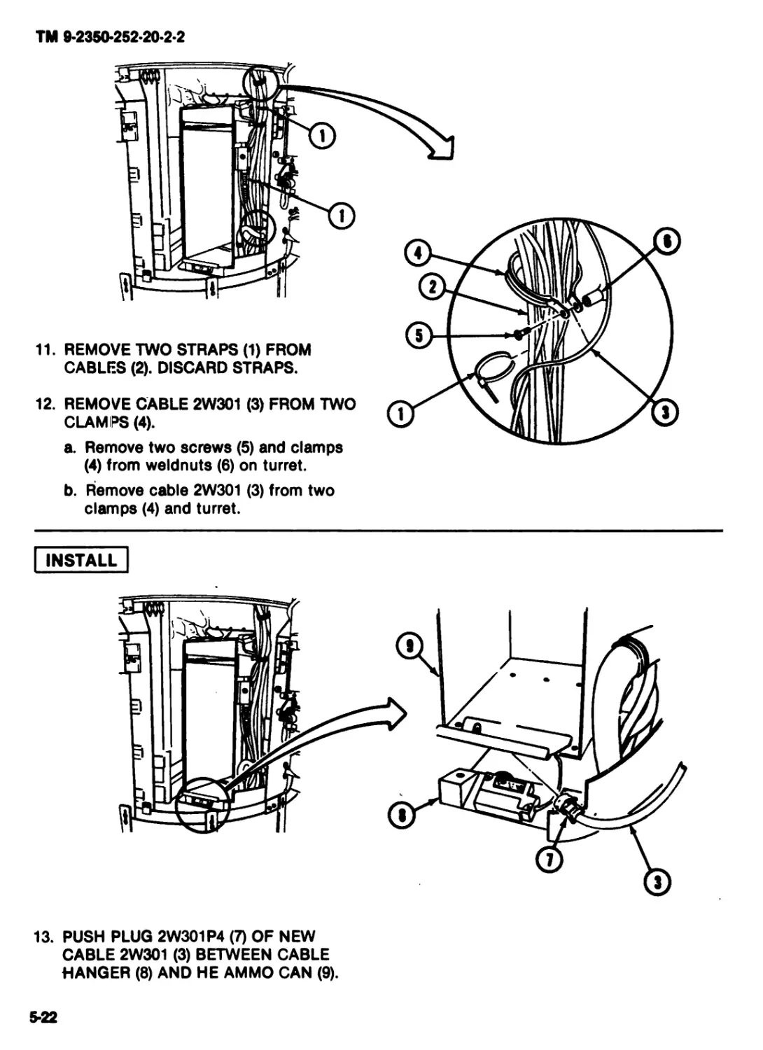
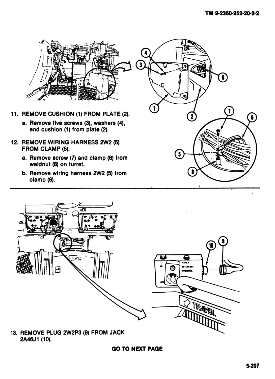
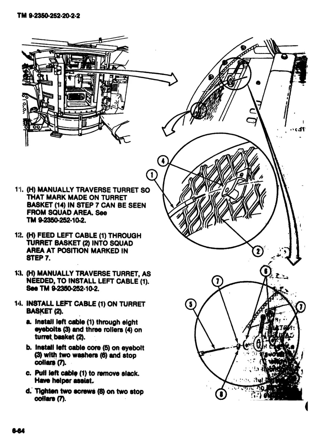
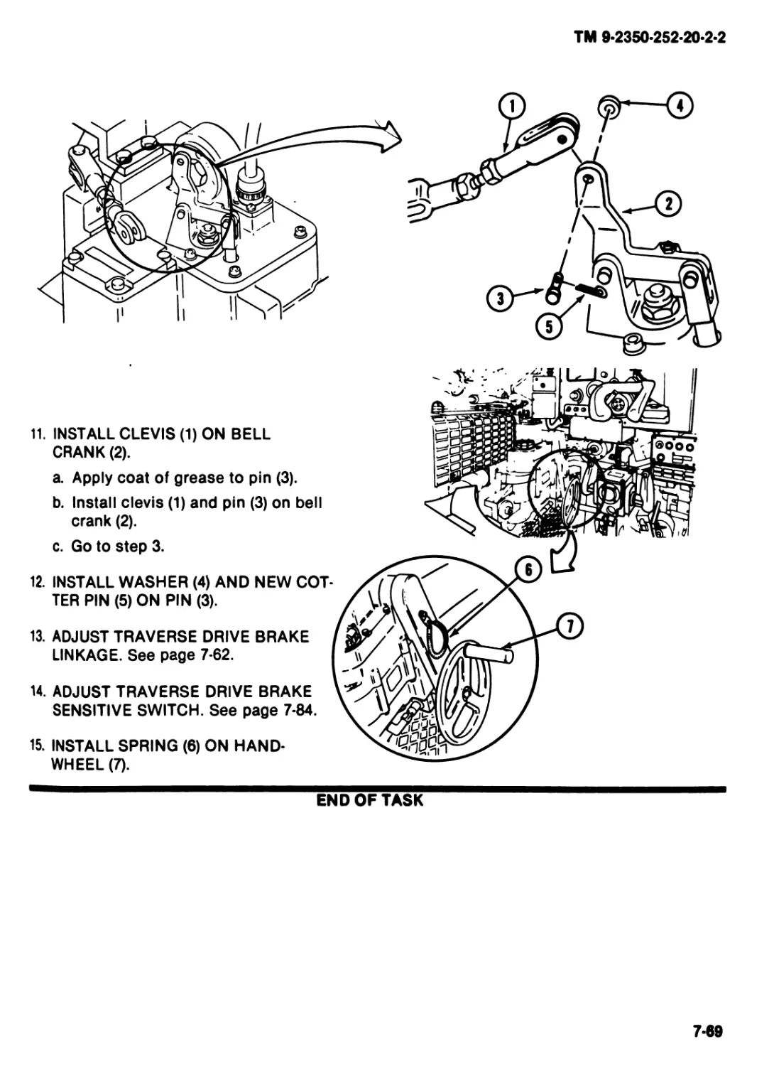
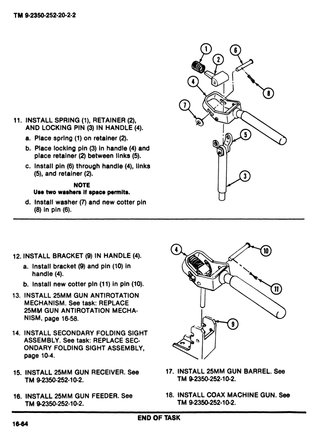
(235001-048-5920)
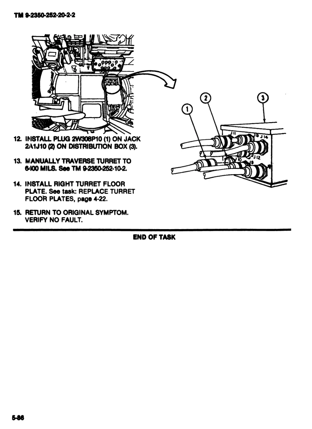
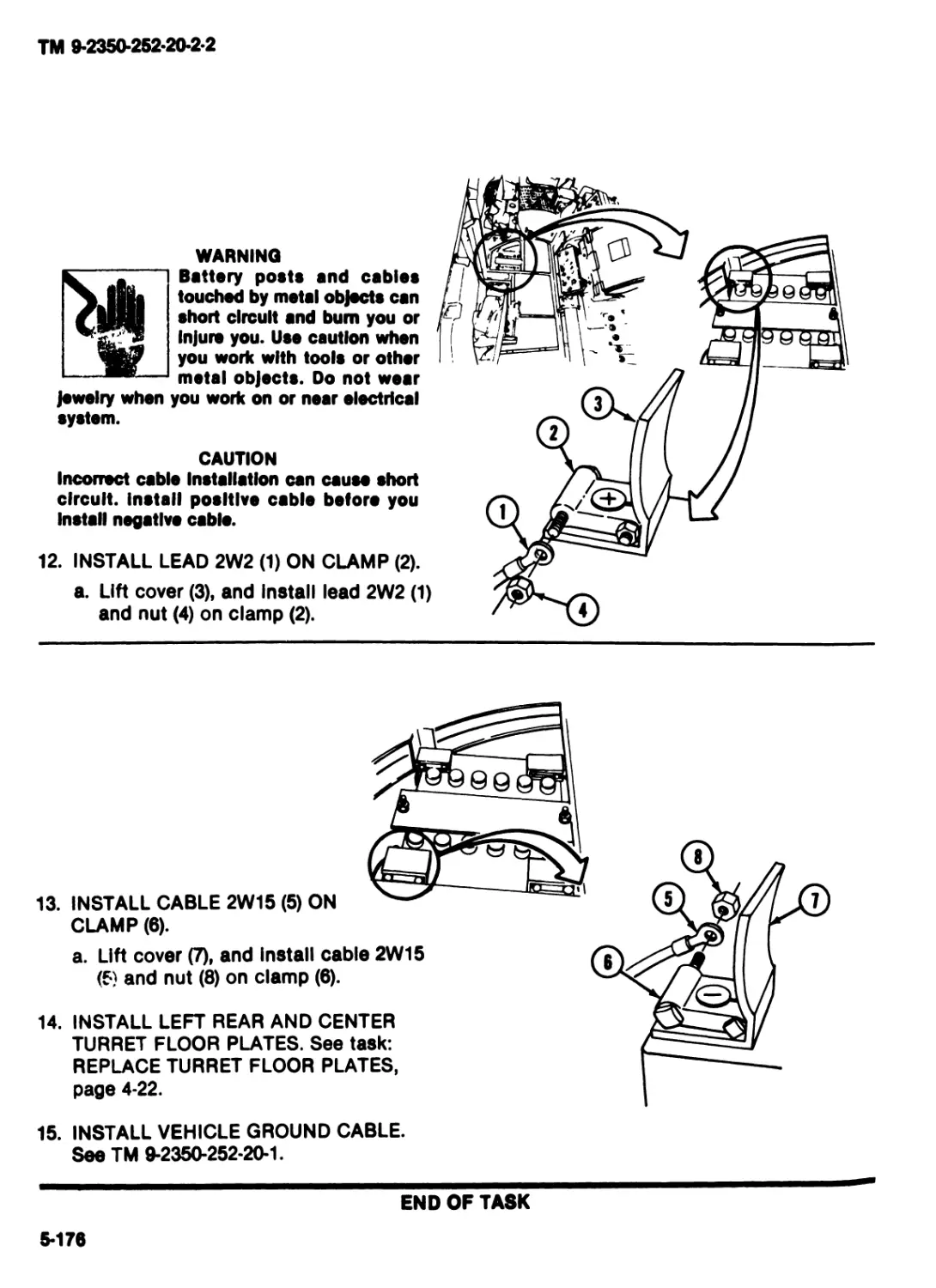
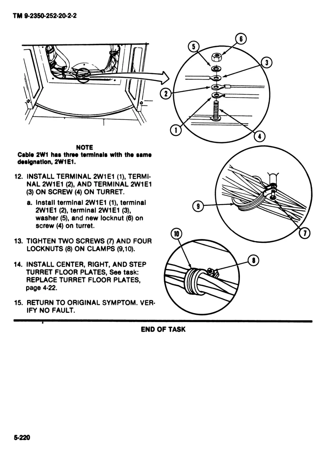
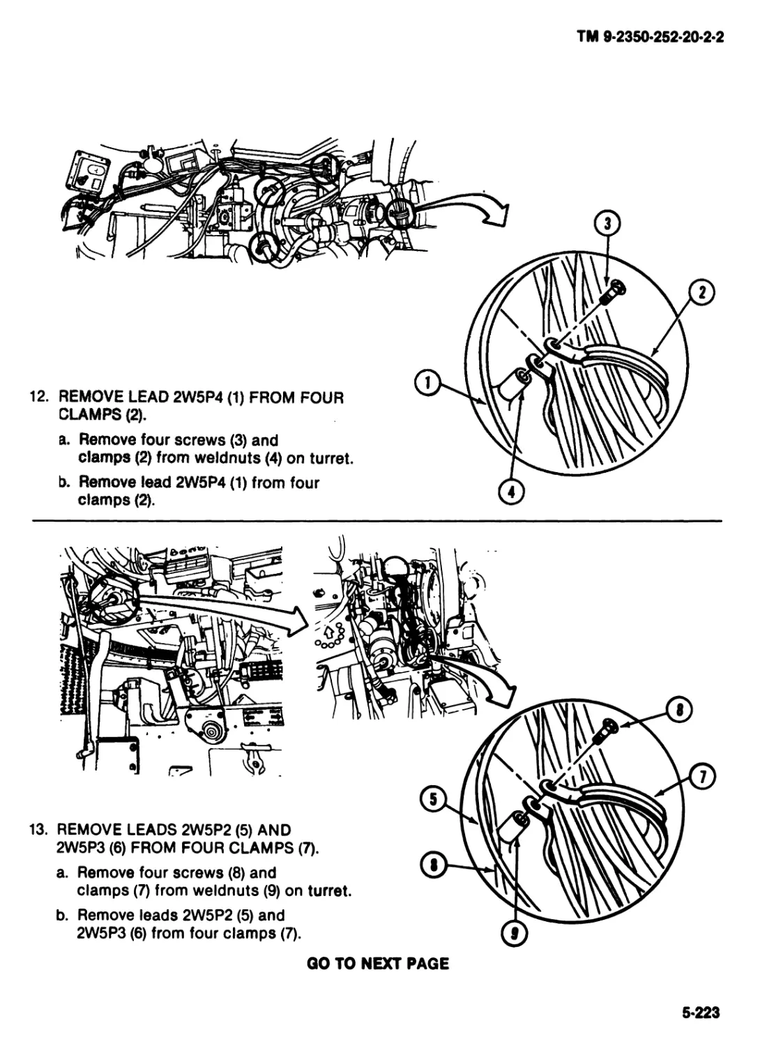
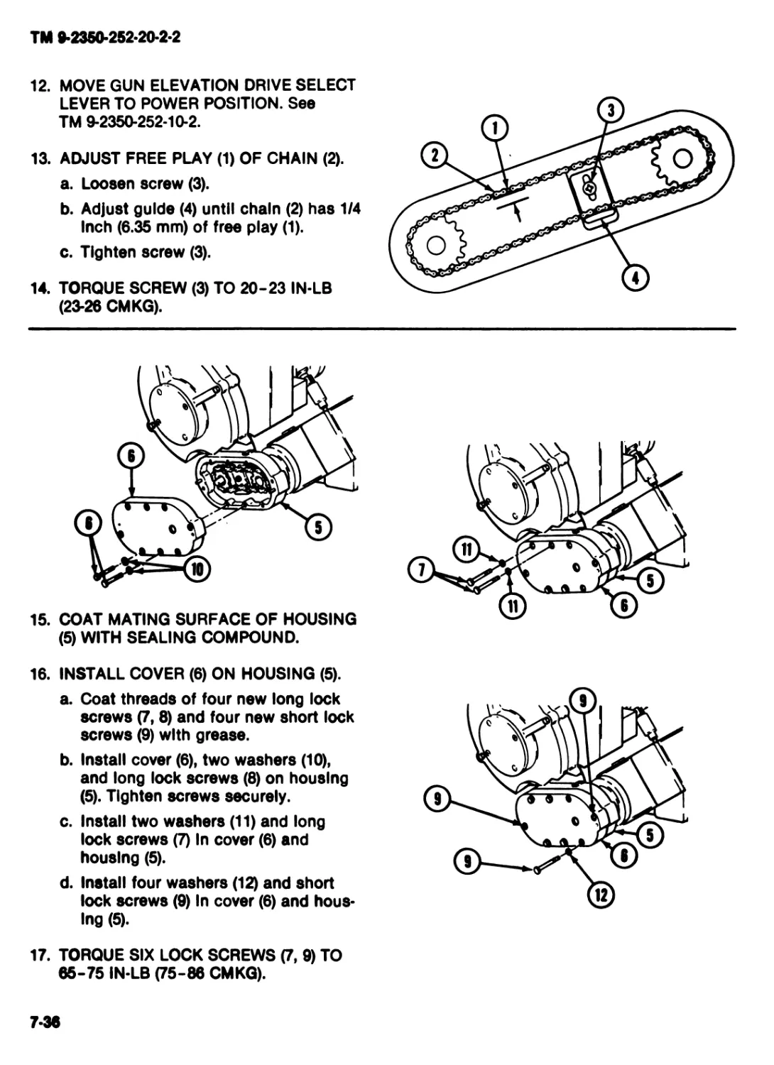
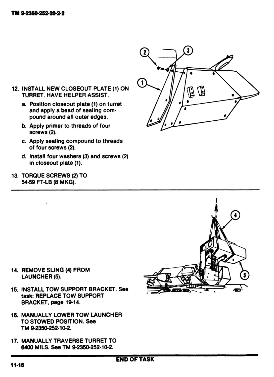
AND
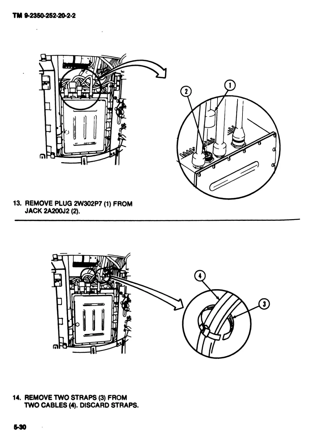
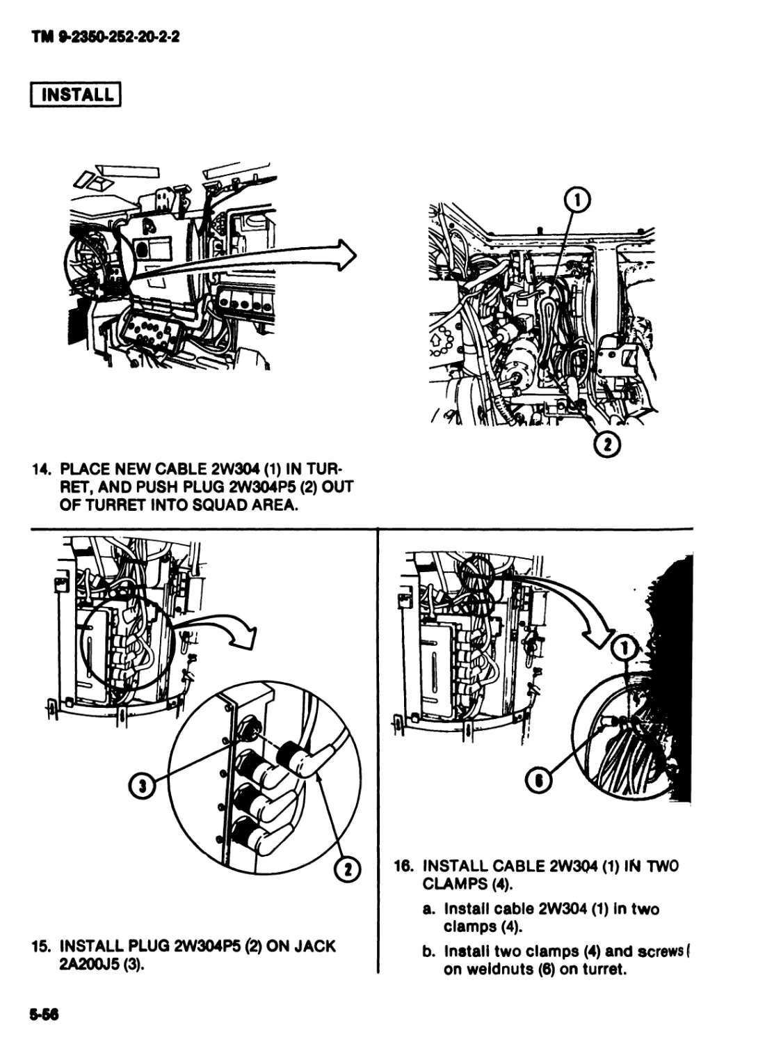
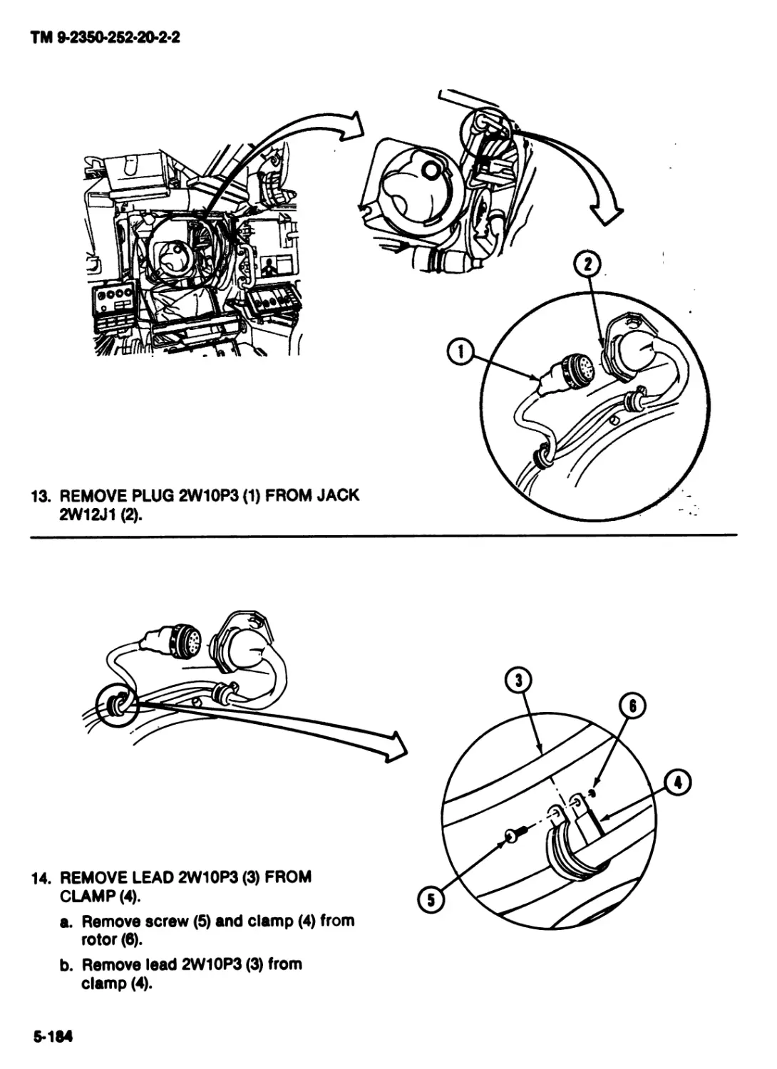
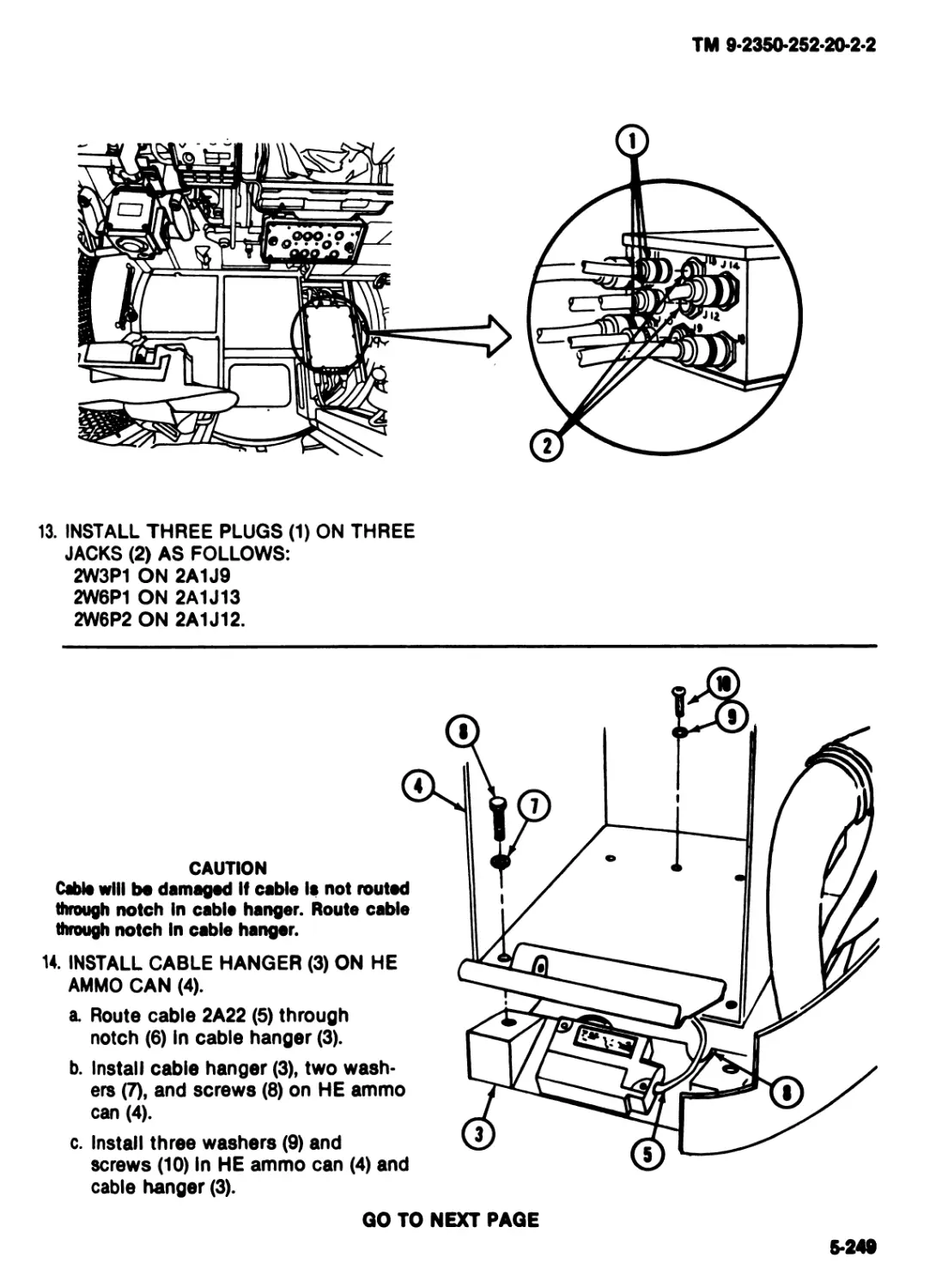
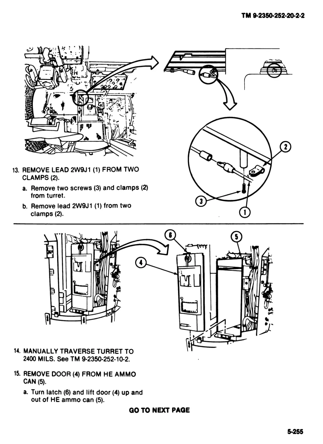
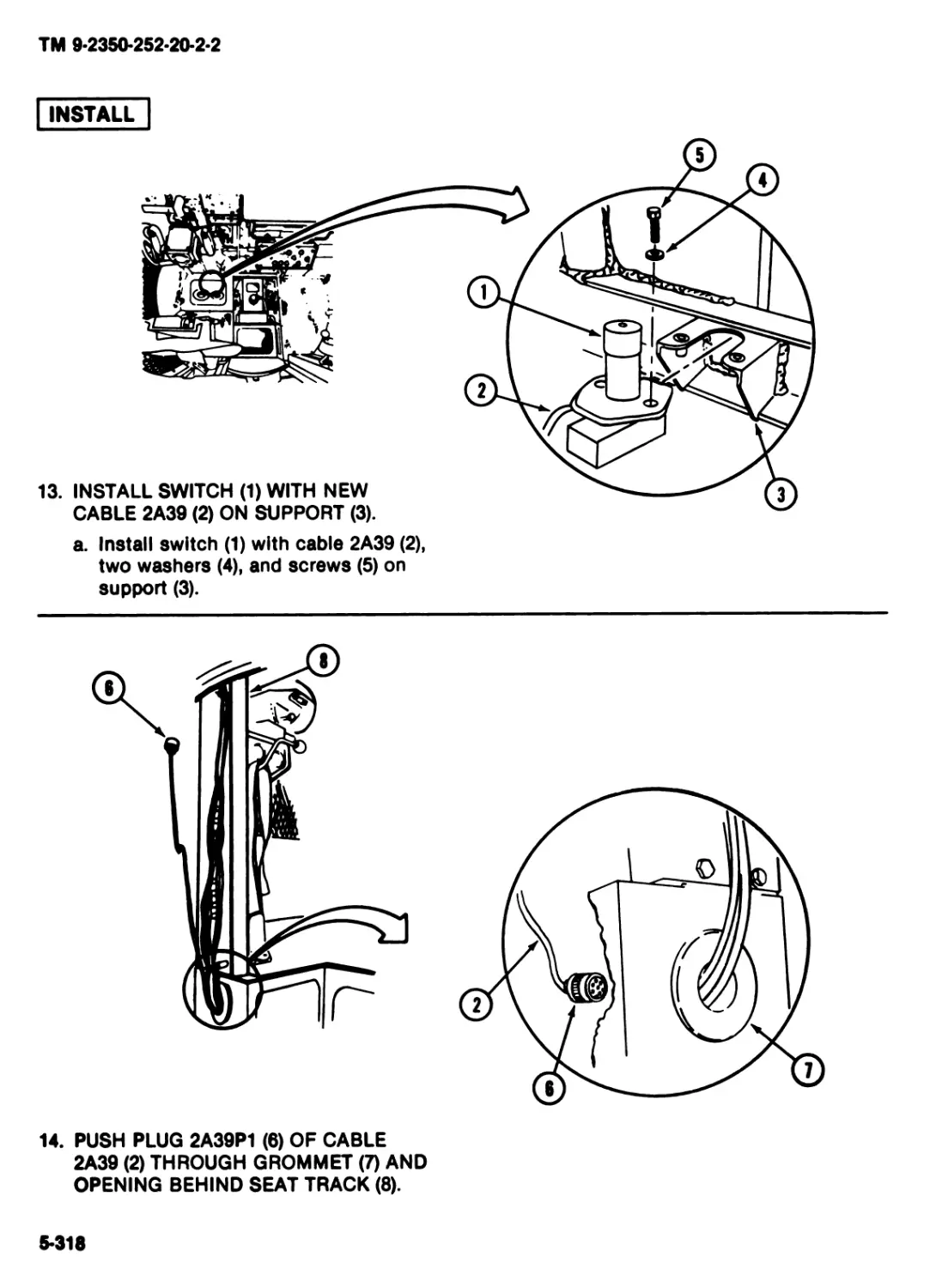
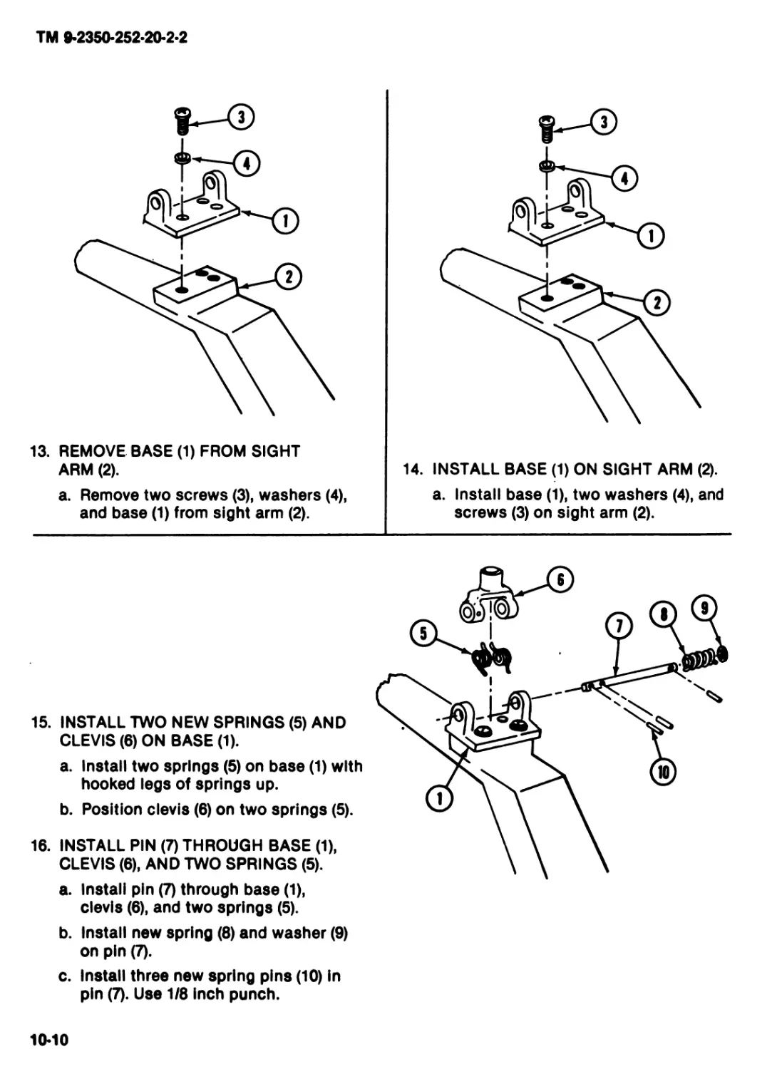
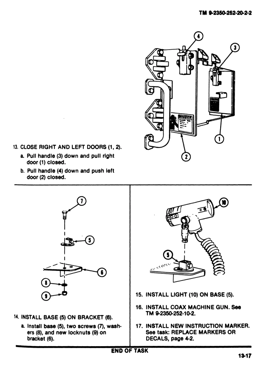
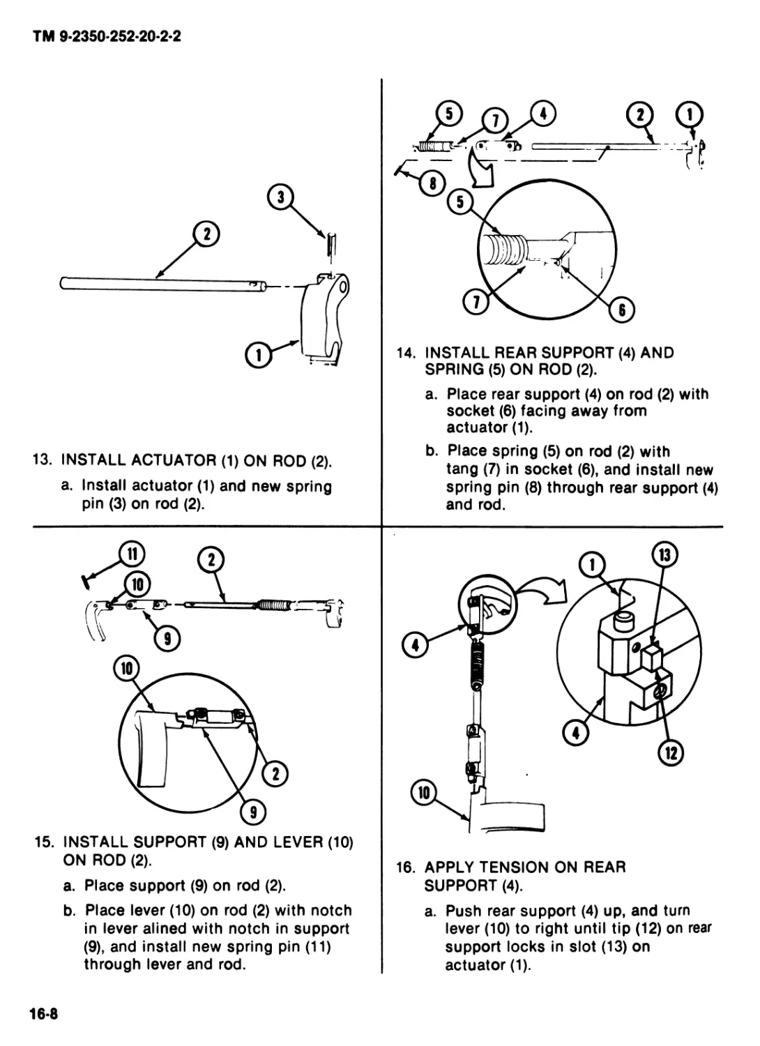
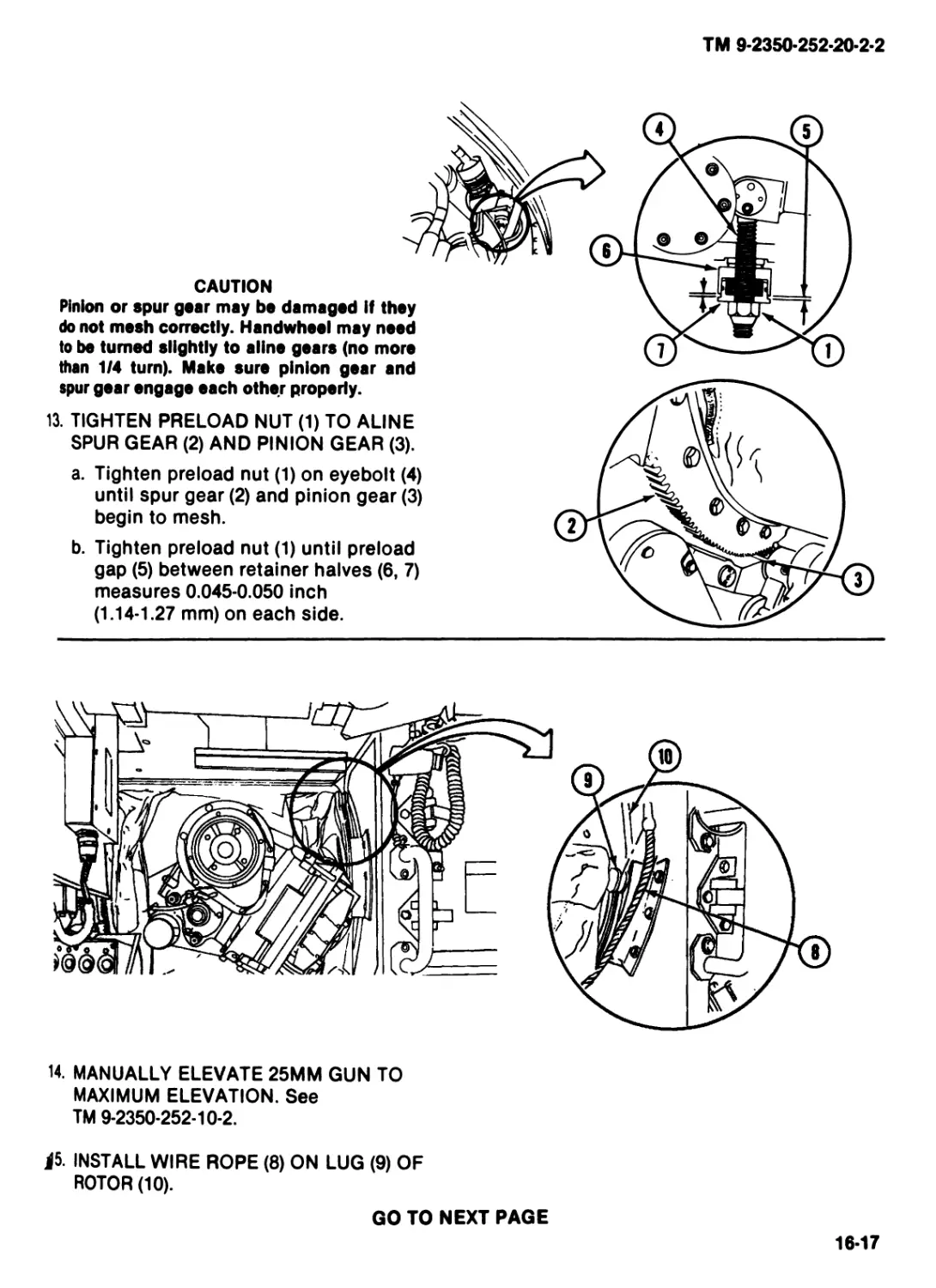
FIGHTING VEHICLE, CAVALRY, М3
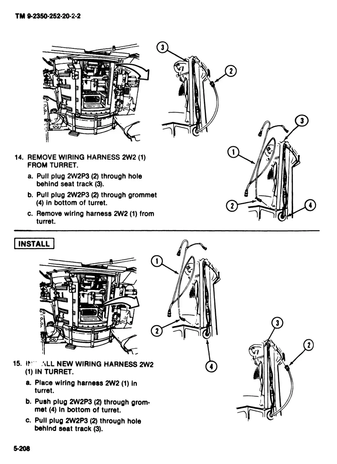
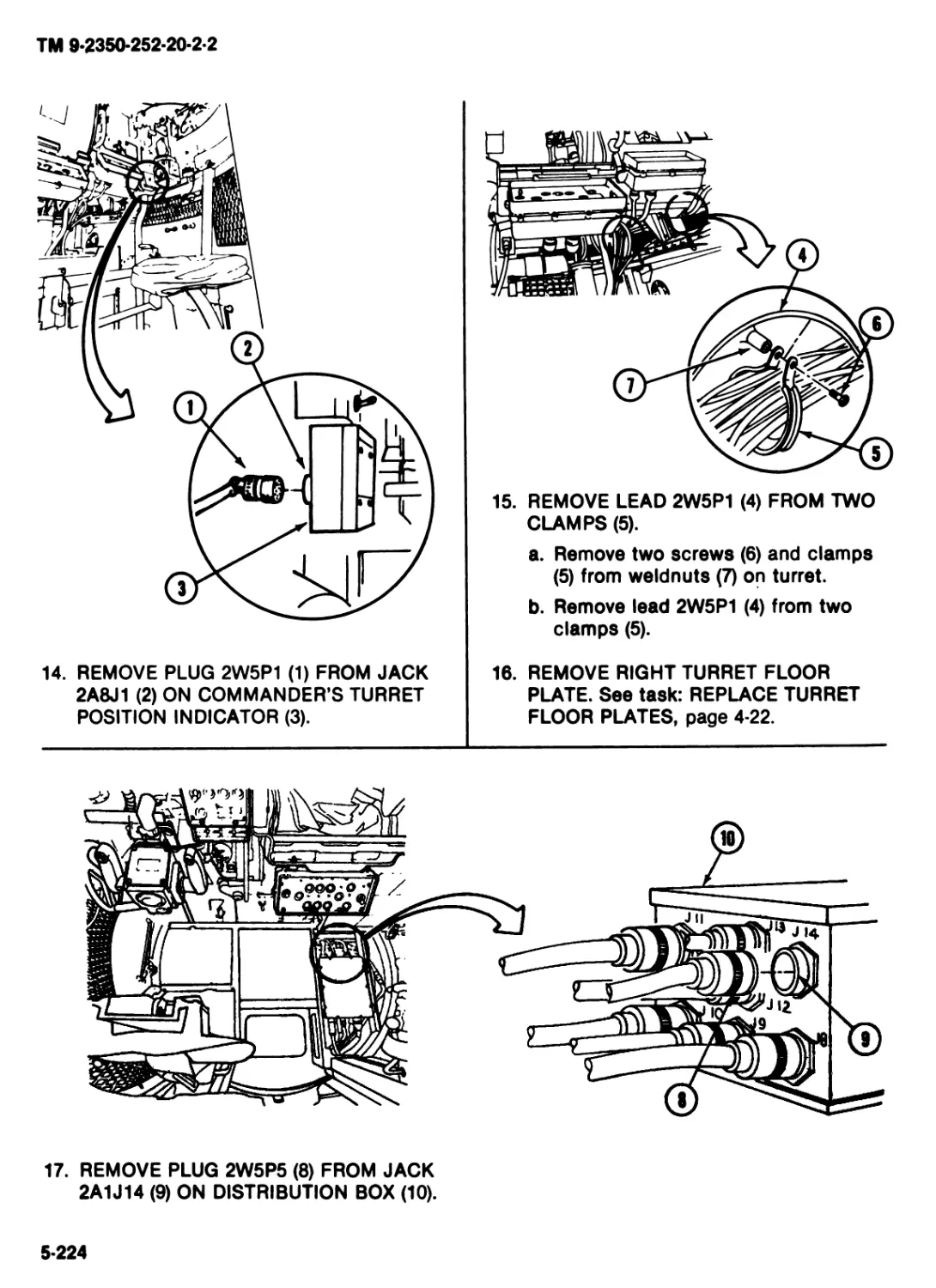
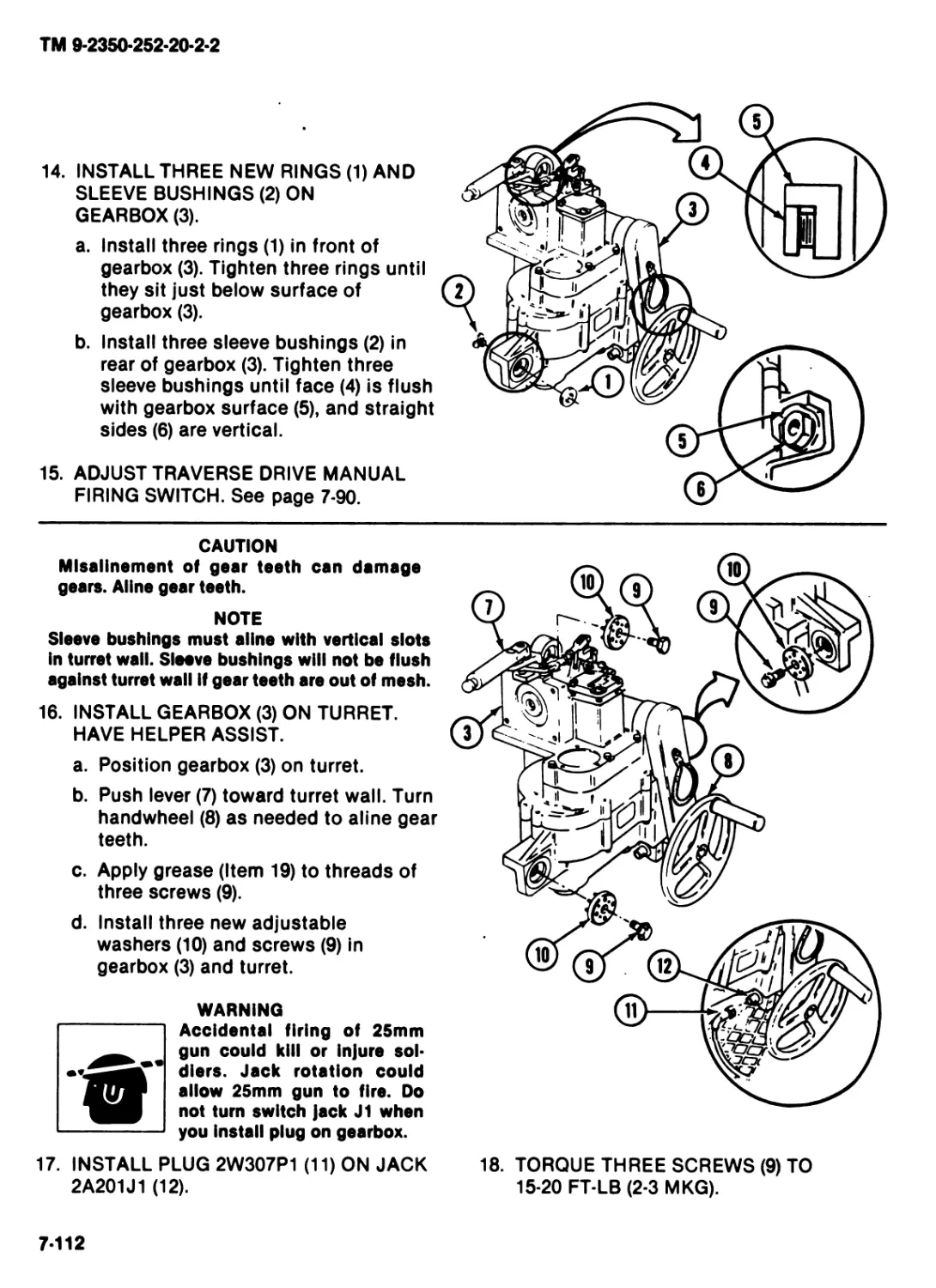
MAINTENANCE OF
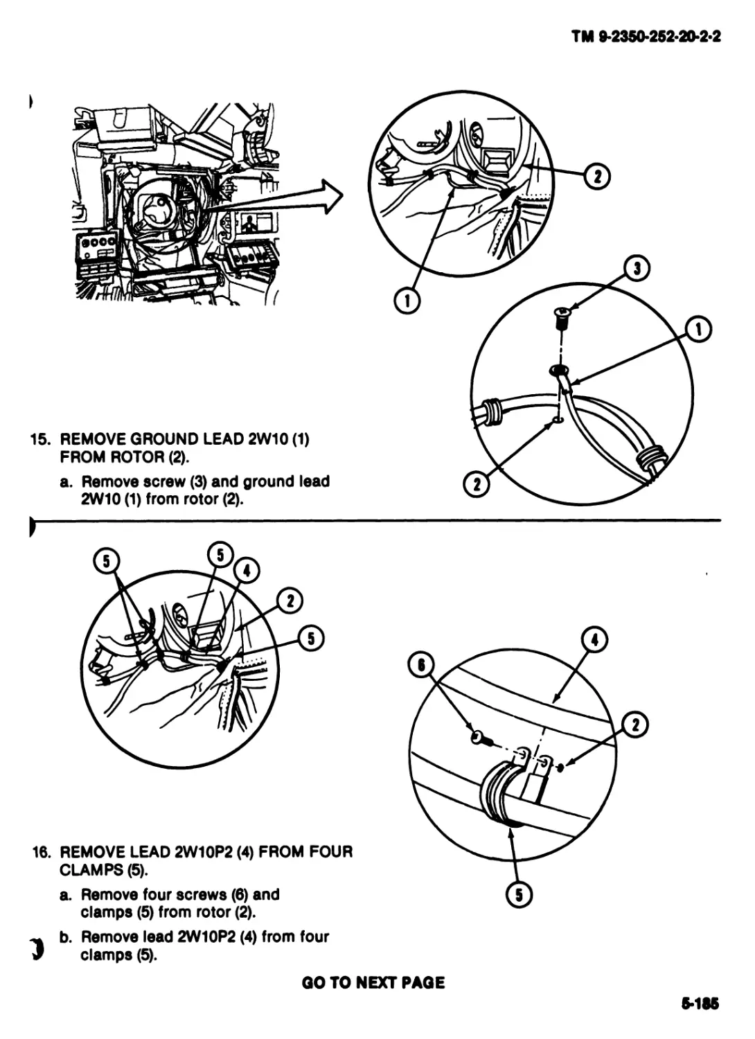
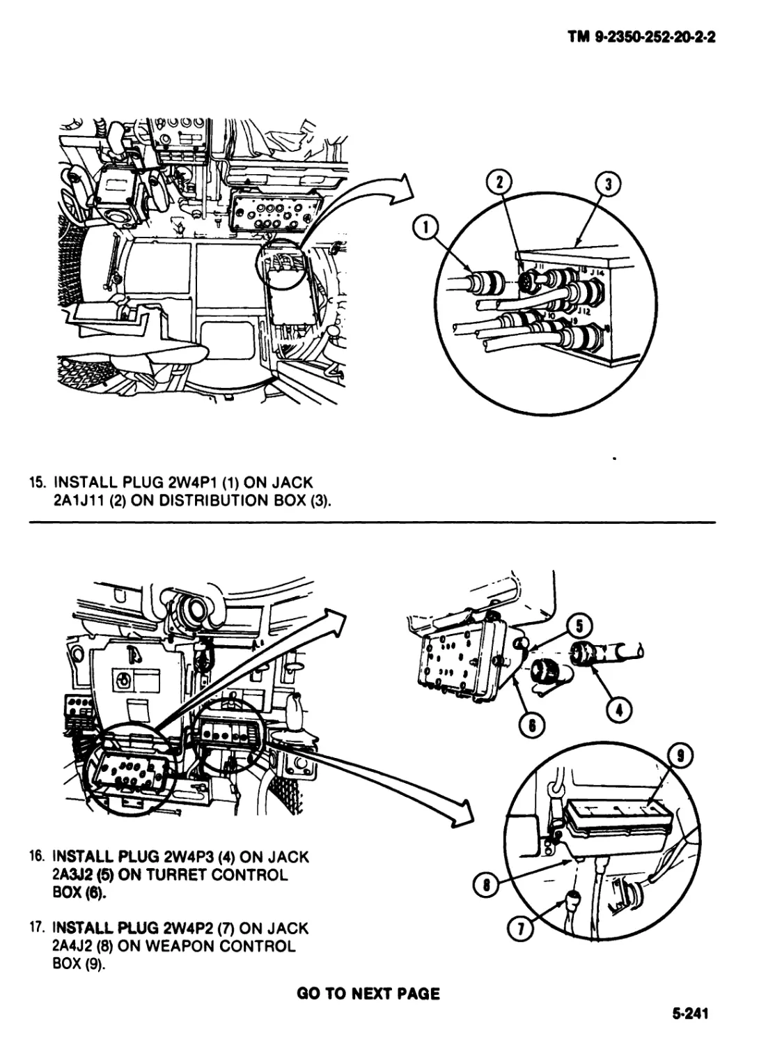
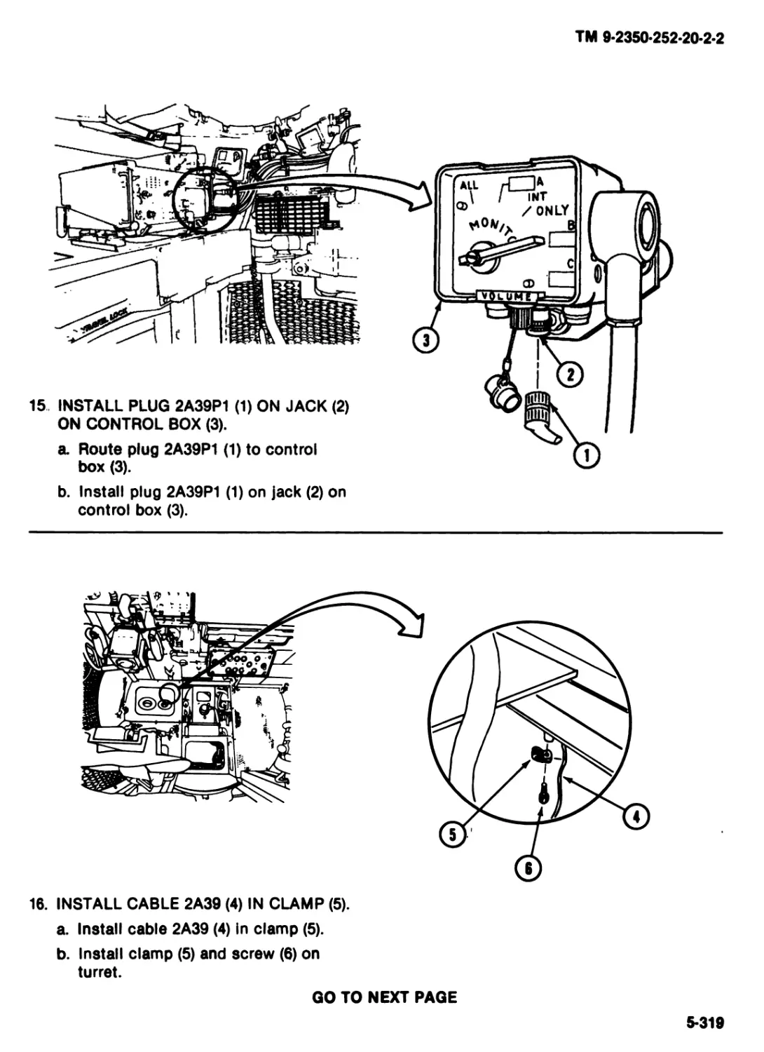
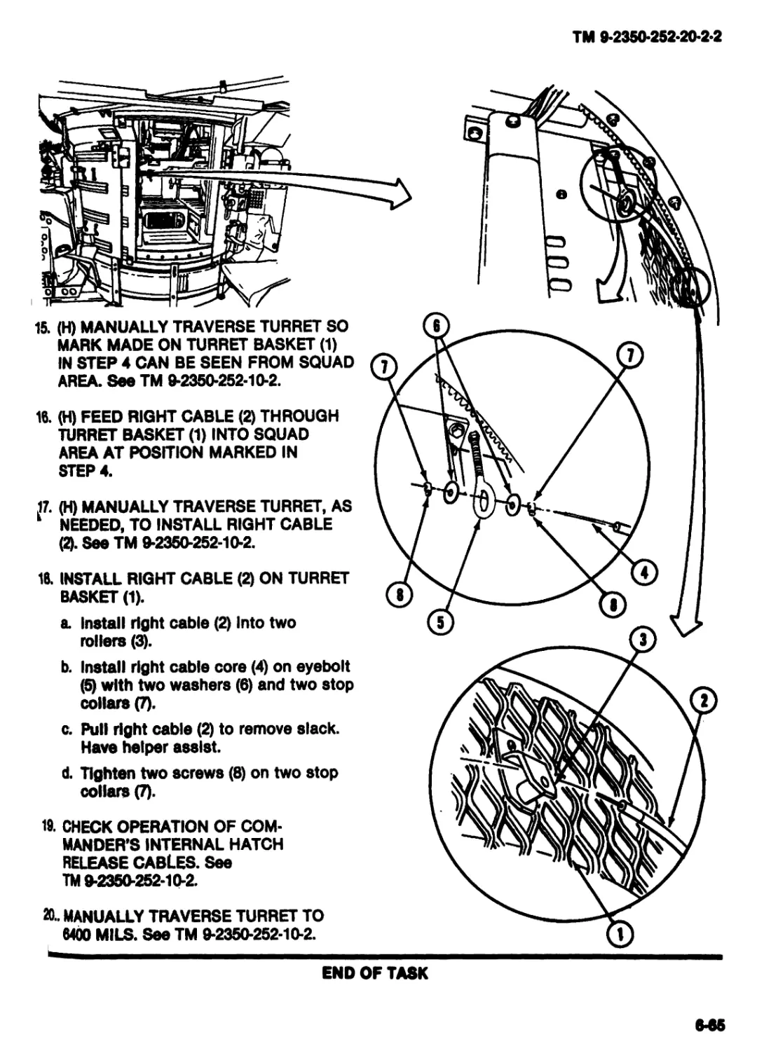
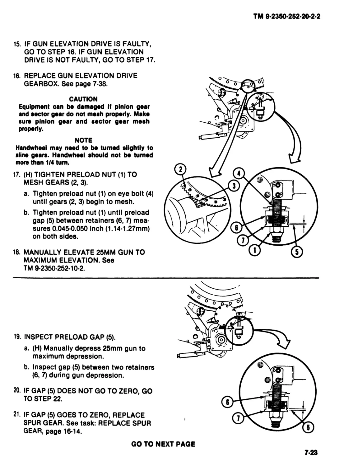
TURRET DRIVE
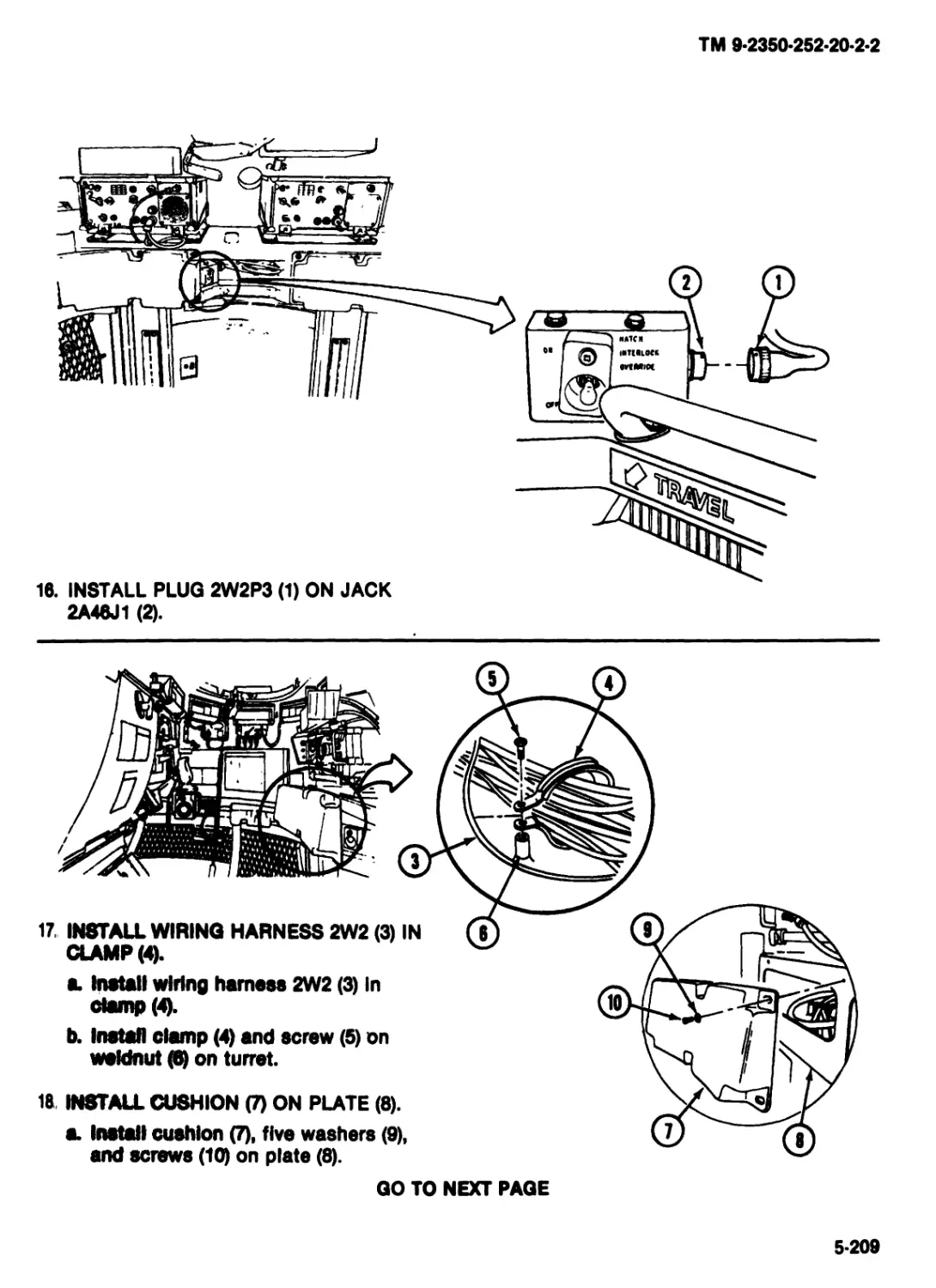
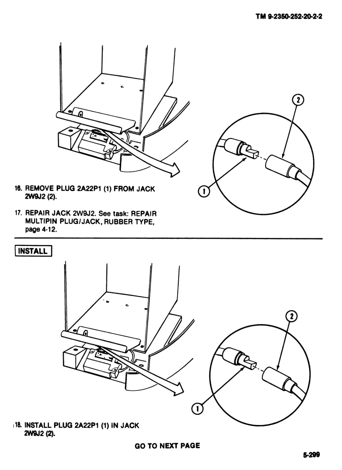
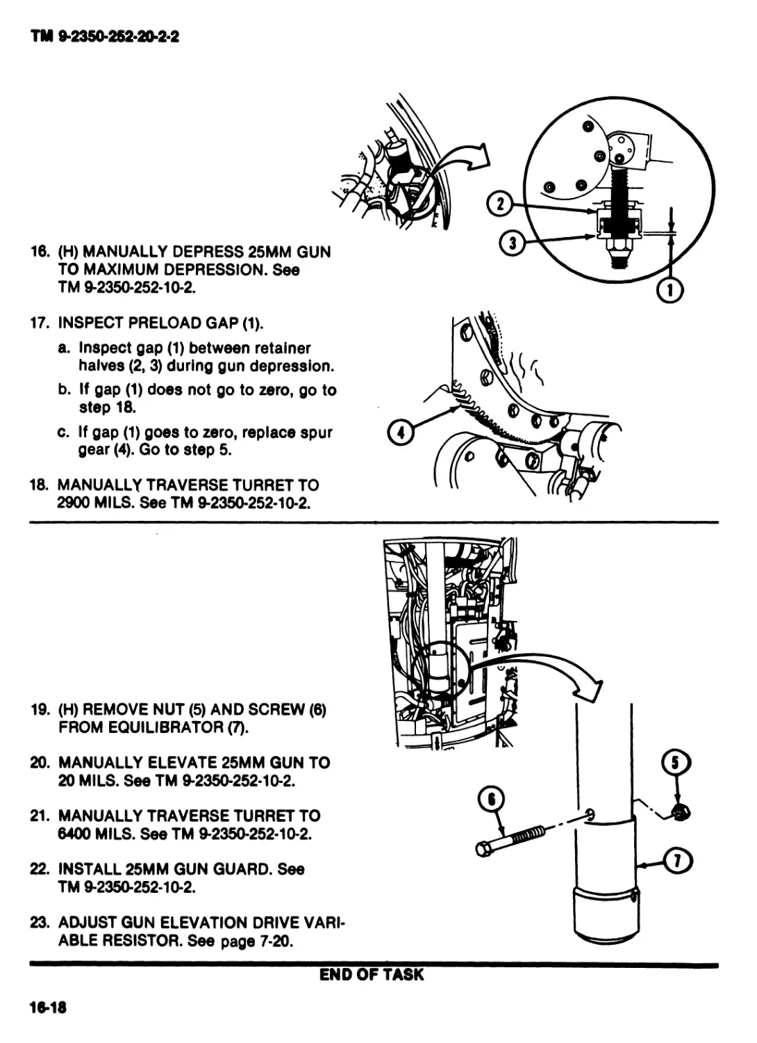
MAINTENANCE OF
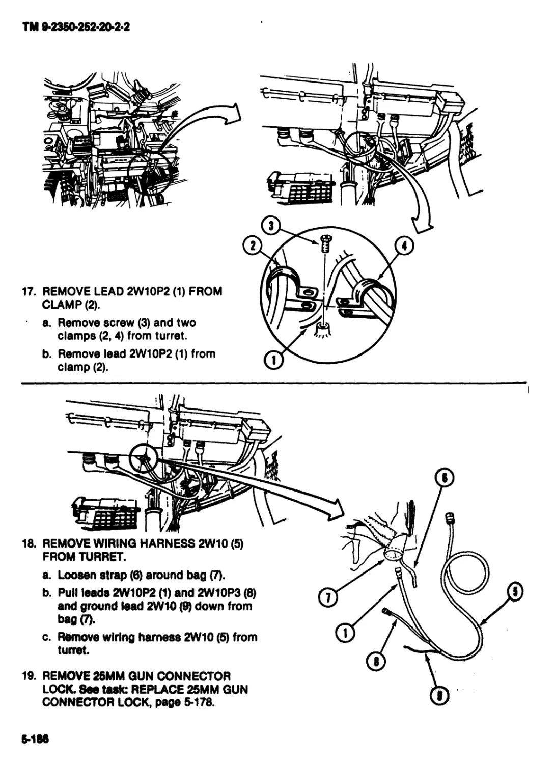
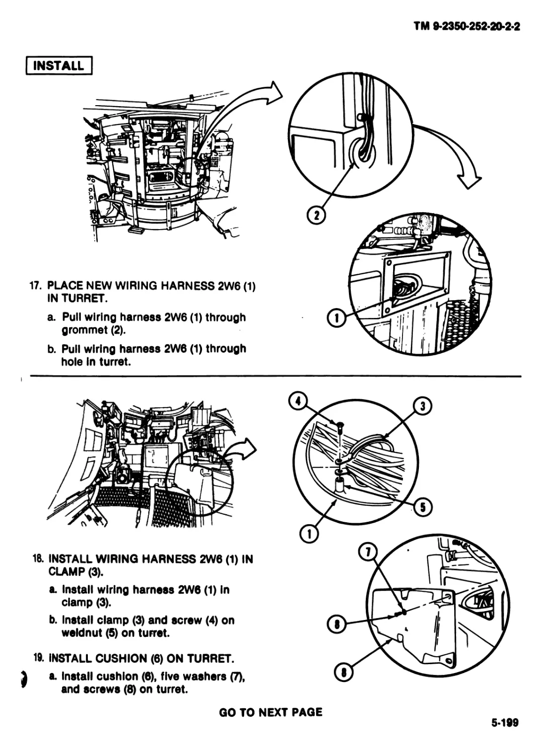
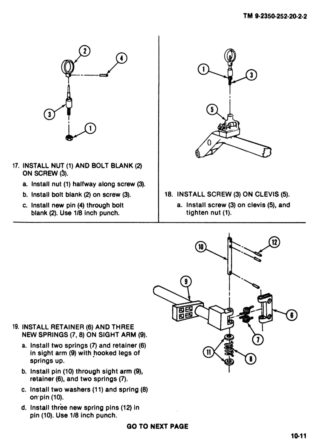
25MMGUNAND
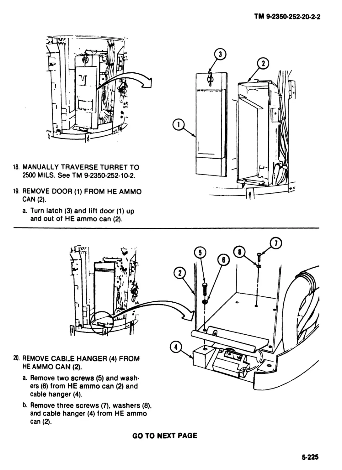
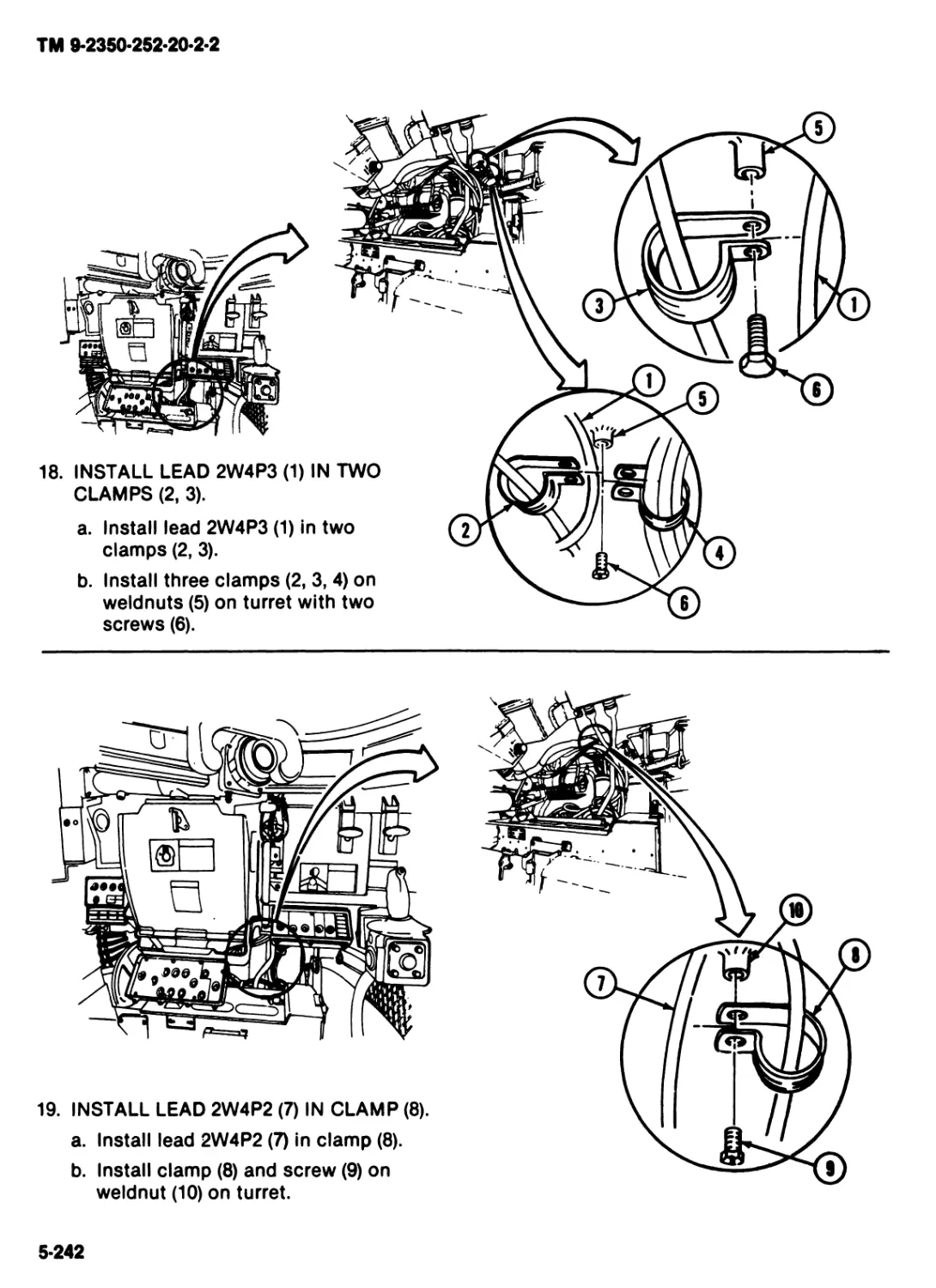
ROTOR
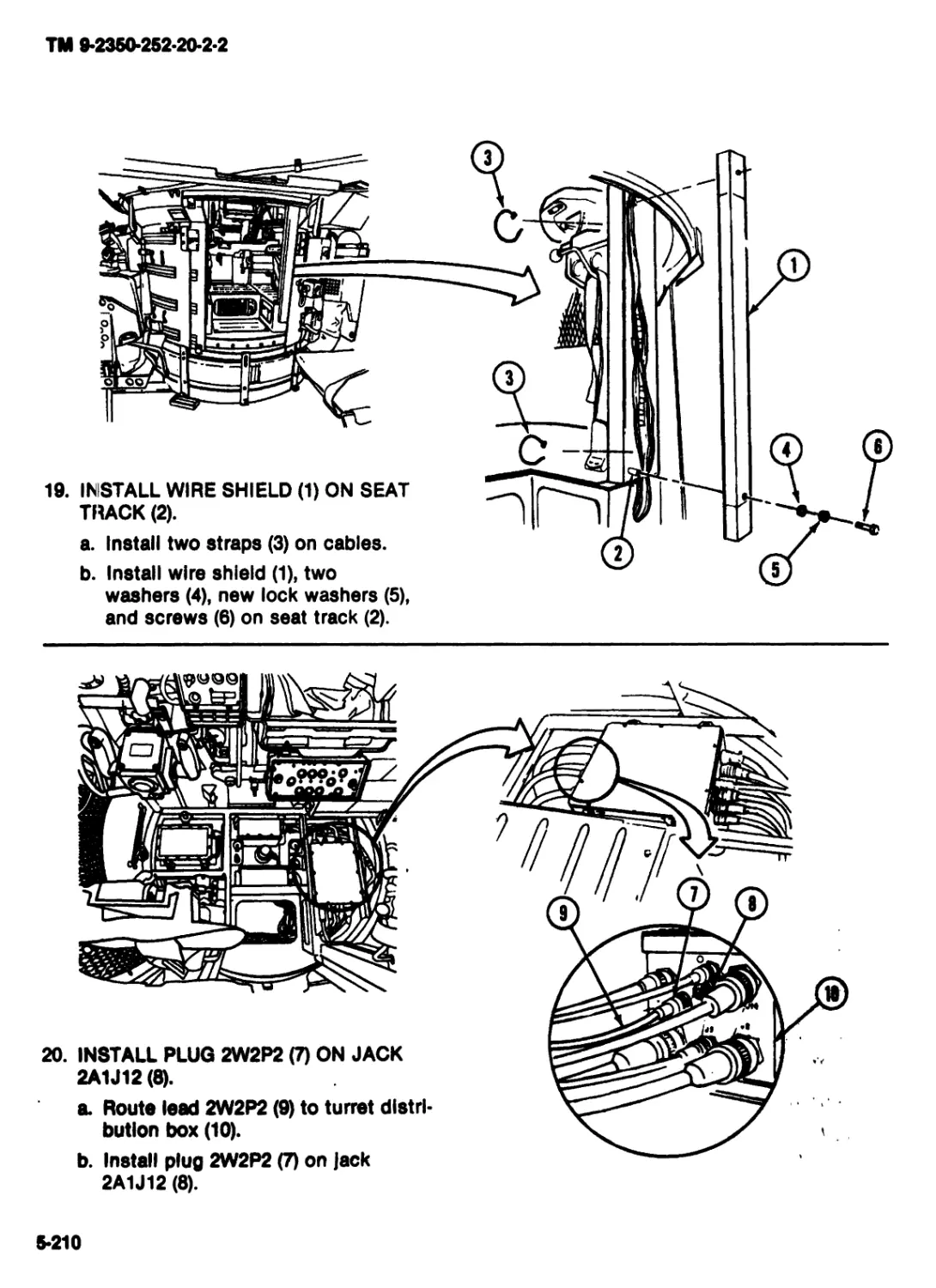
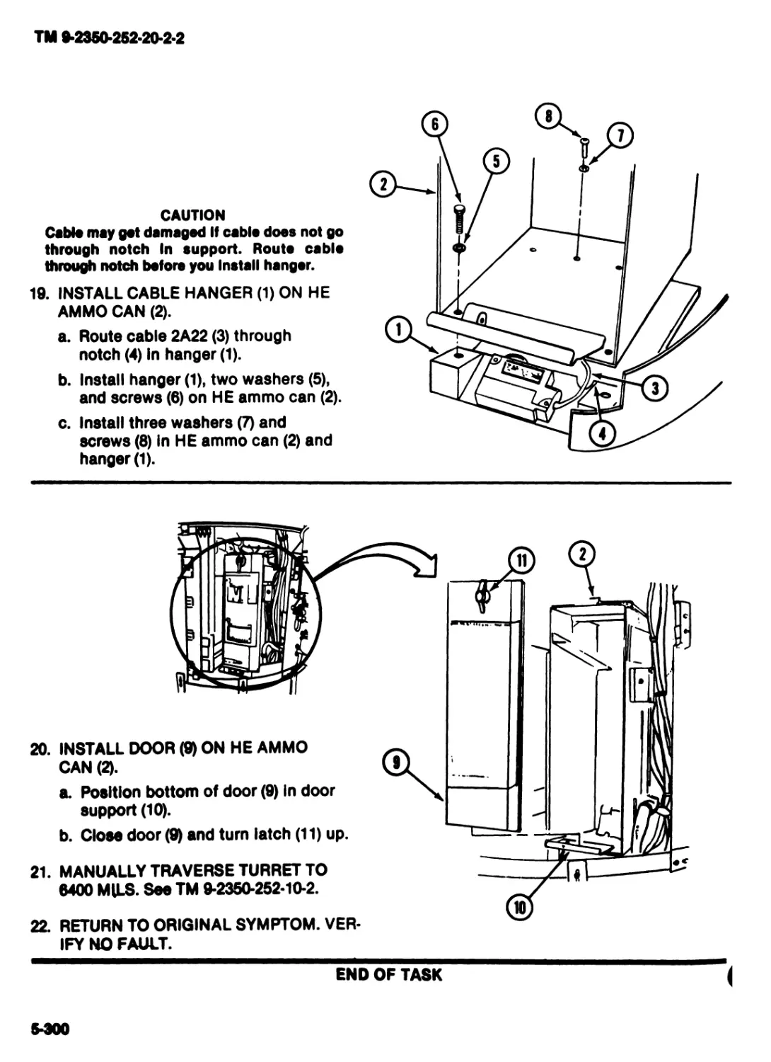
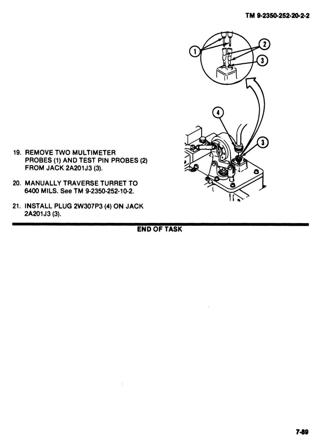
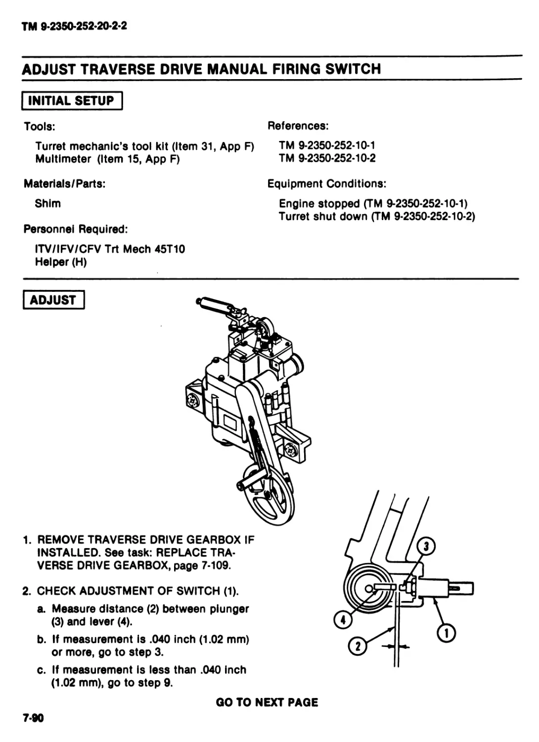
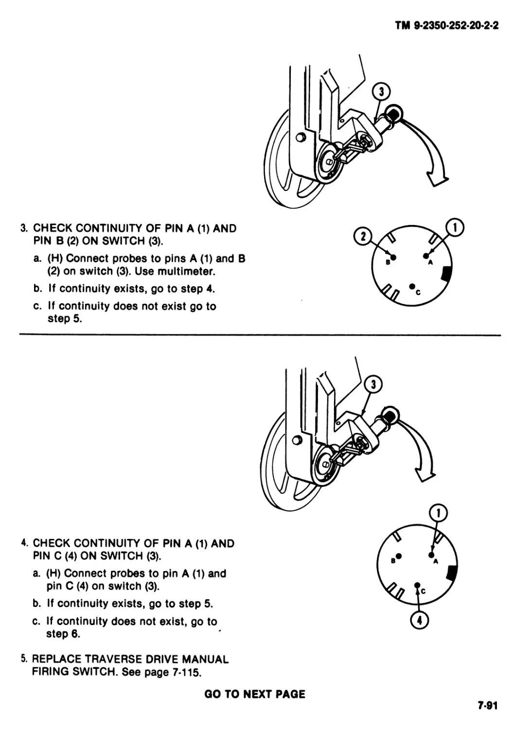
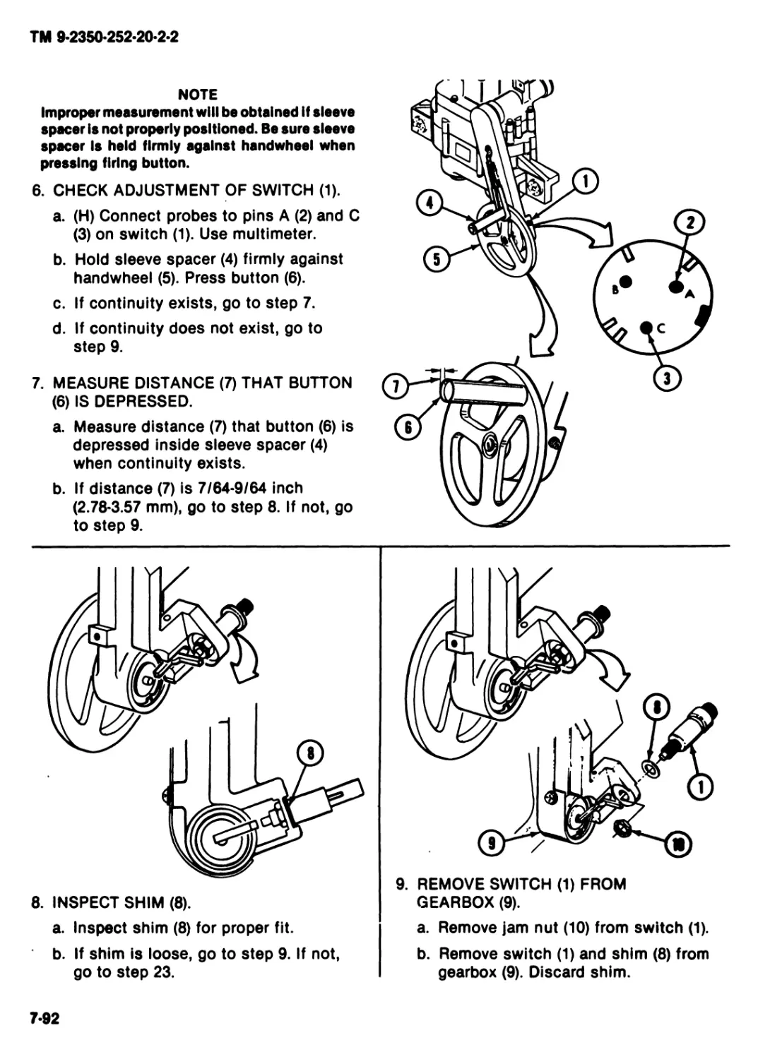
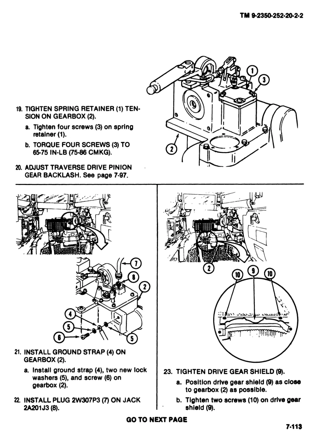
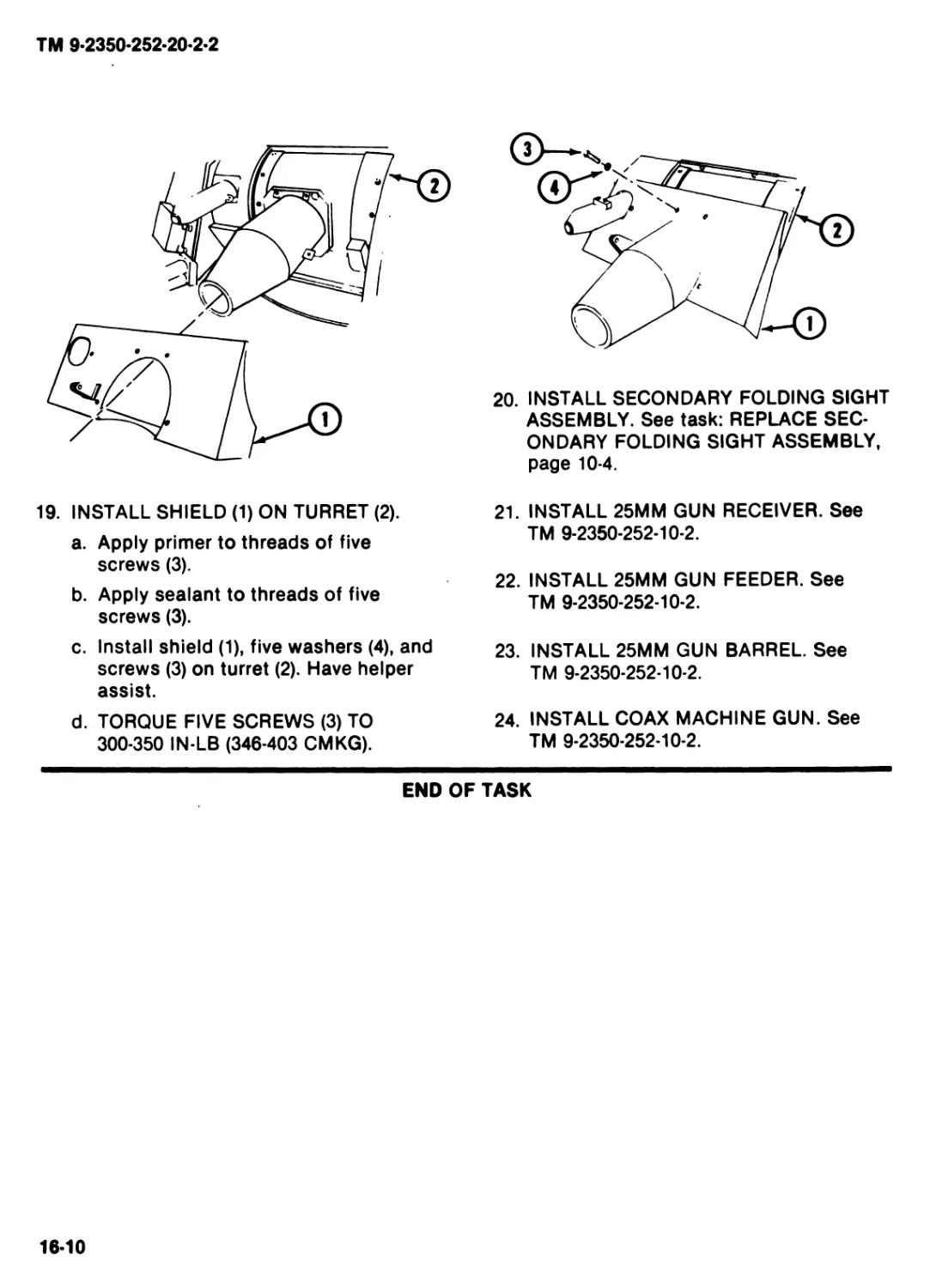
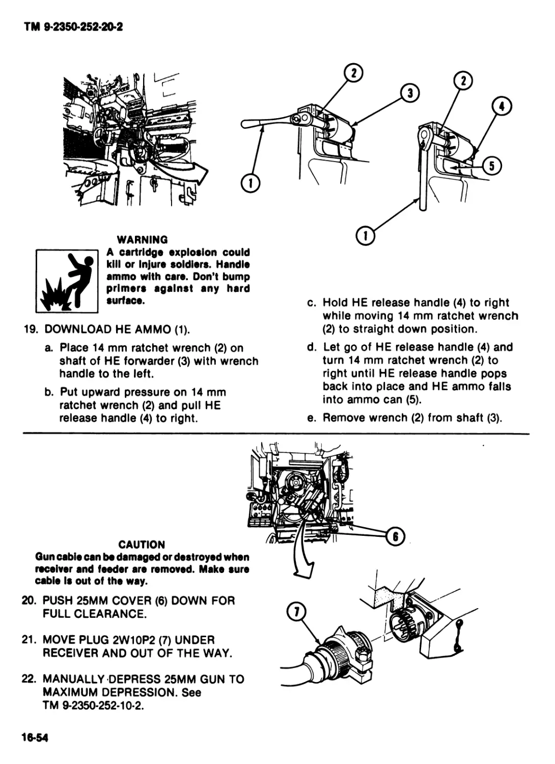
(2350-01-049-2695)
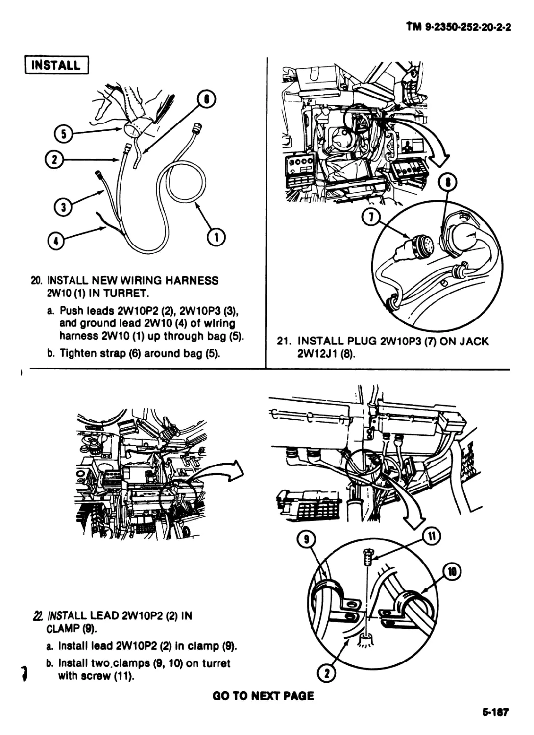
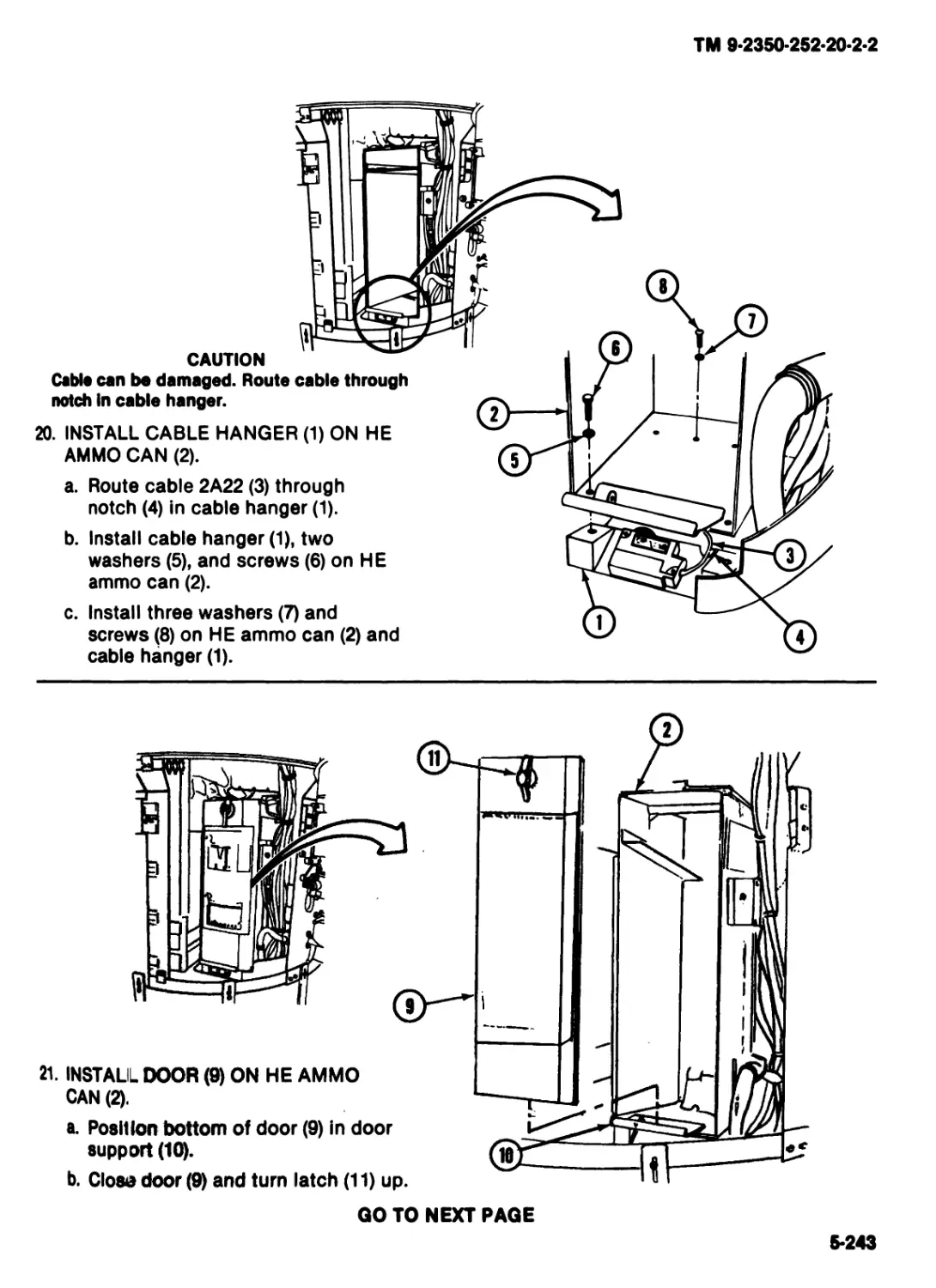
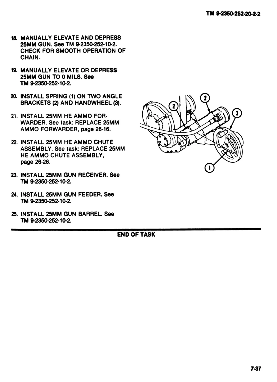
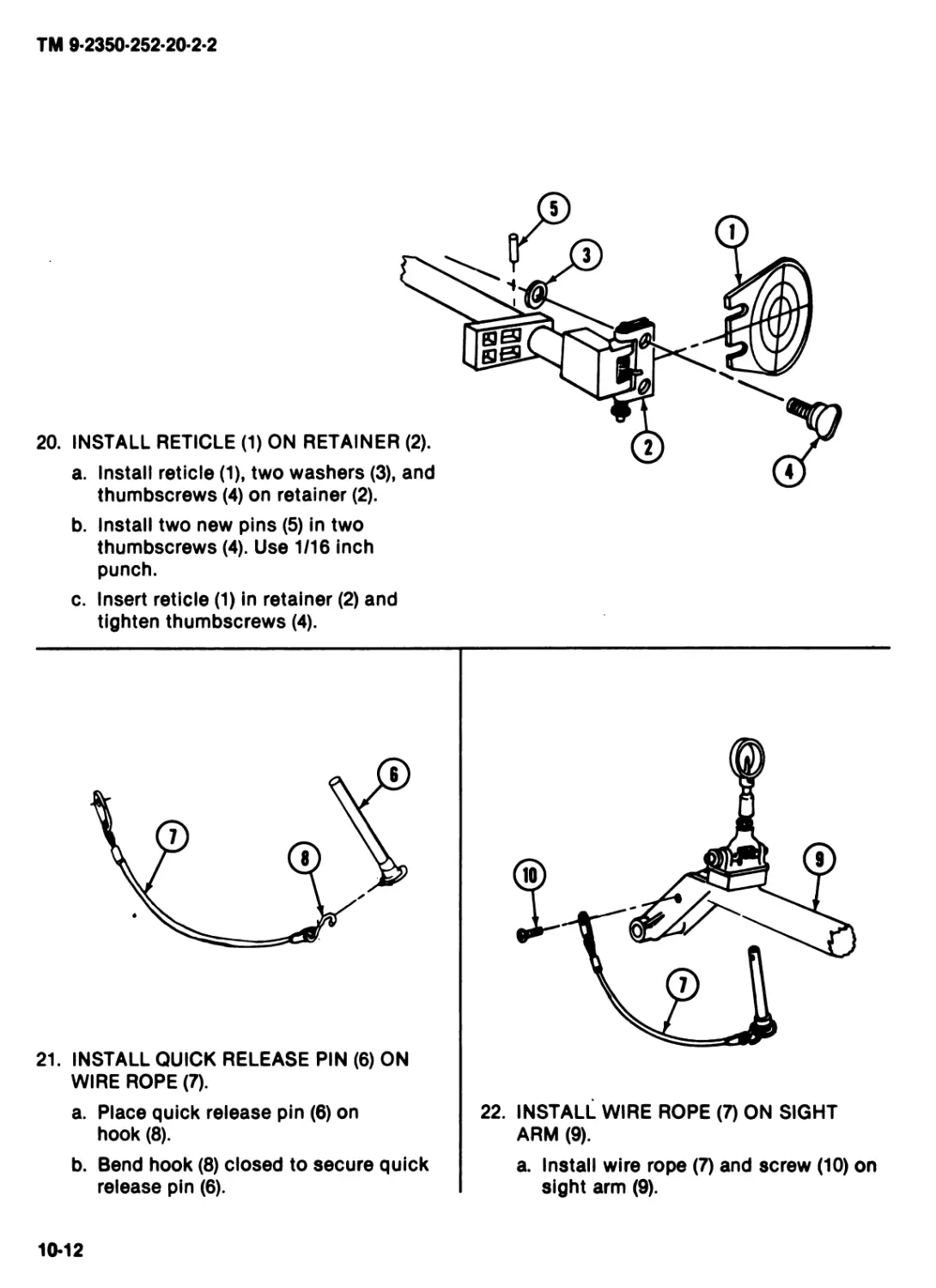
TURRET
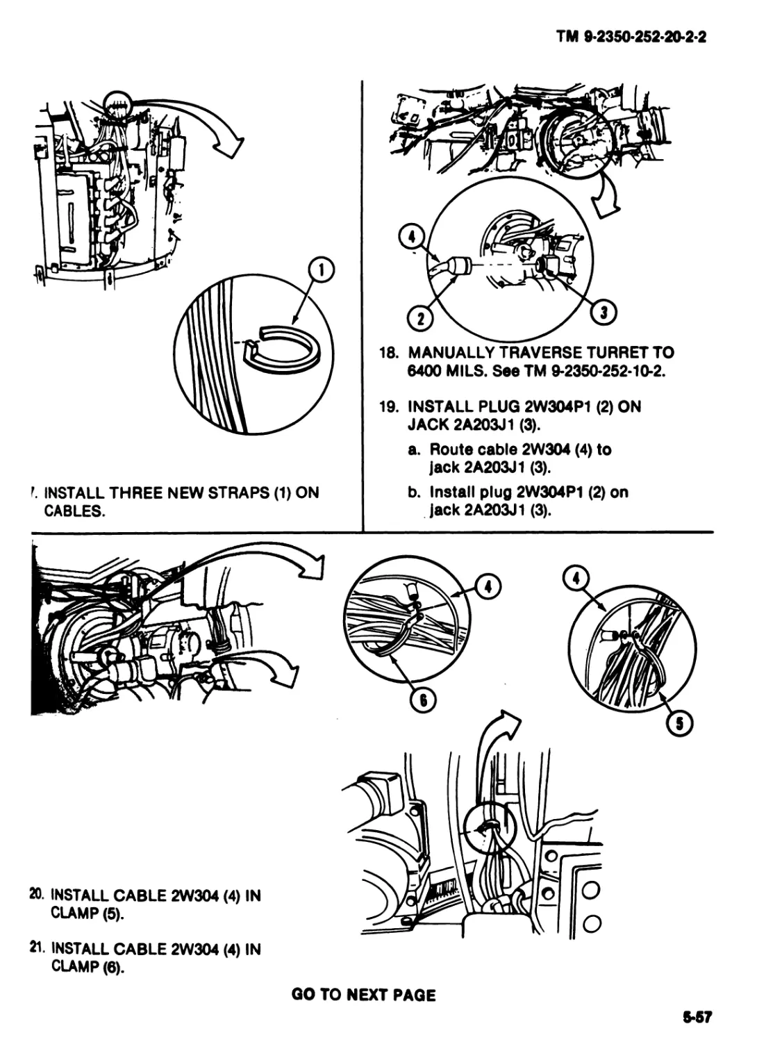
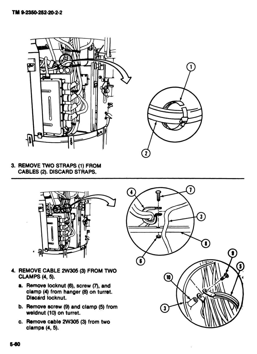
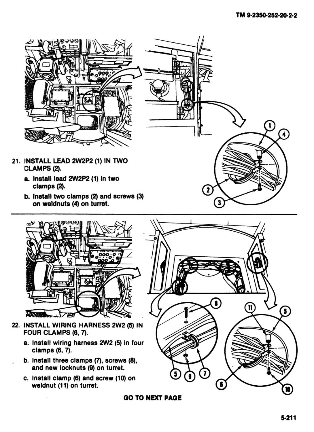
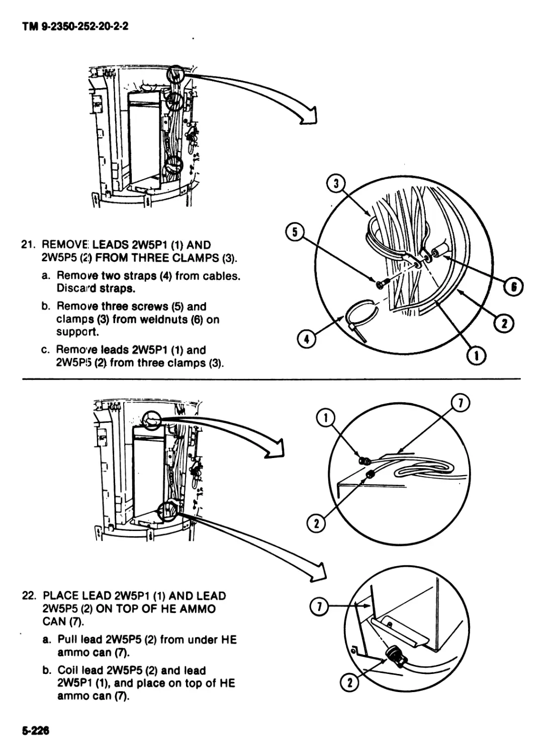
ALPHABETICAL
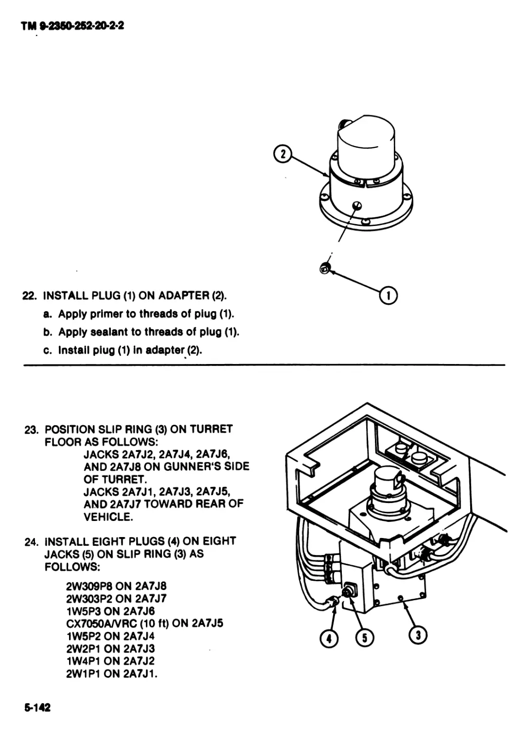
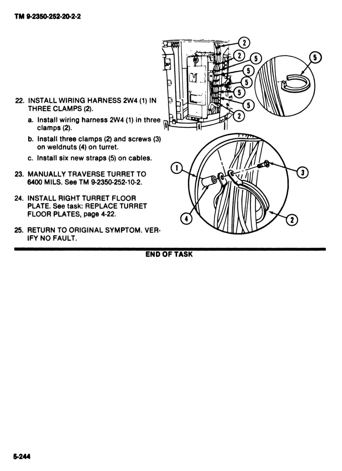
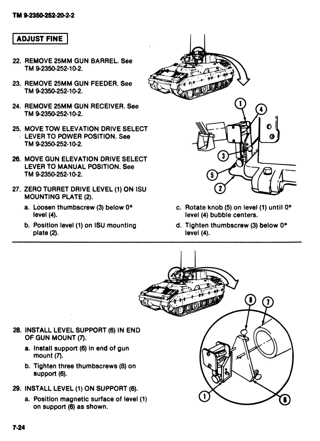
INDEX
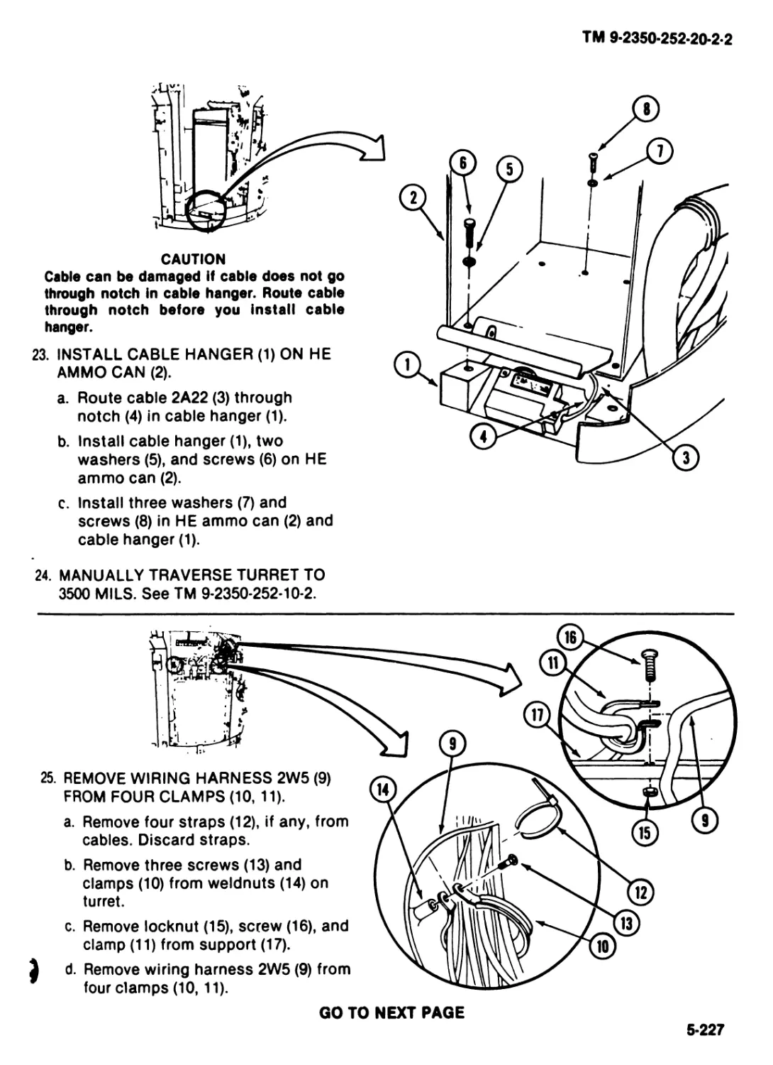
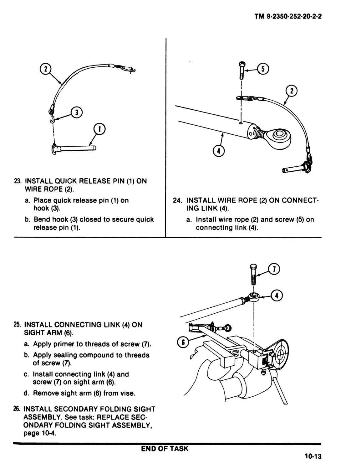
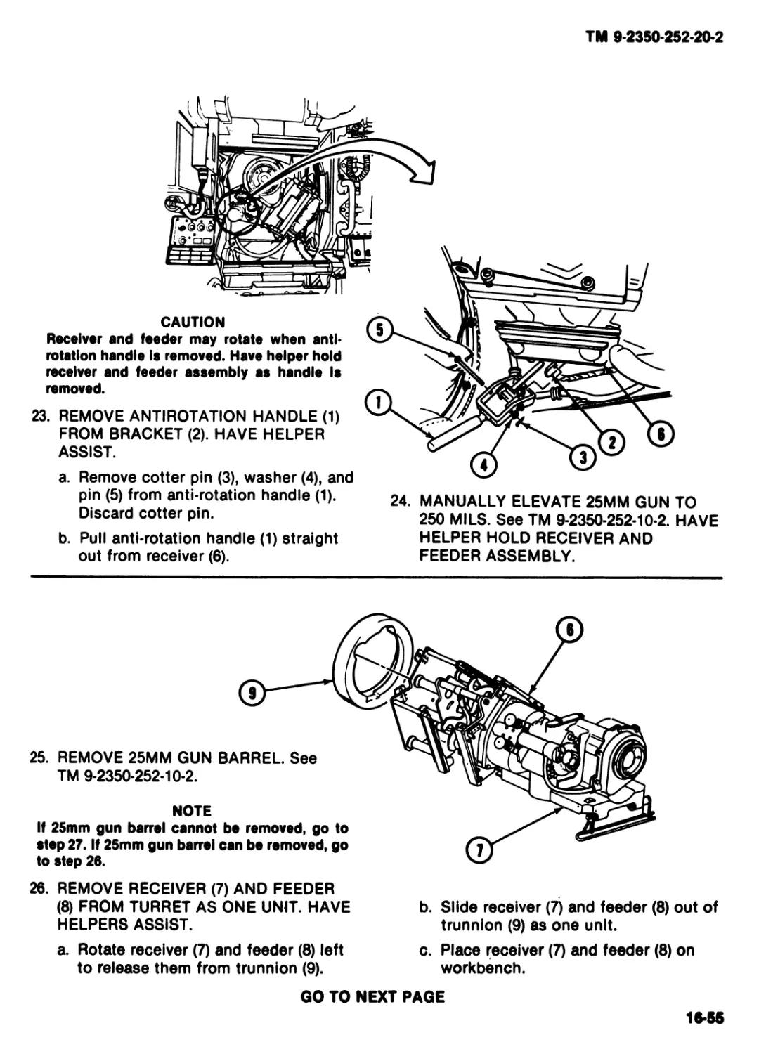
HEADQUARTERS,
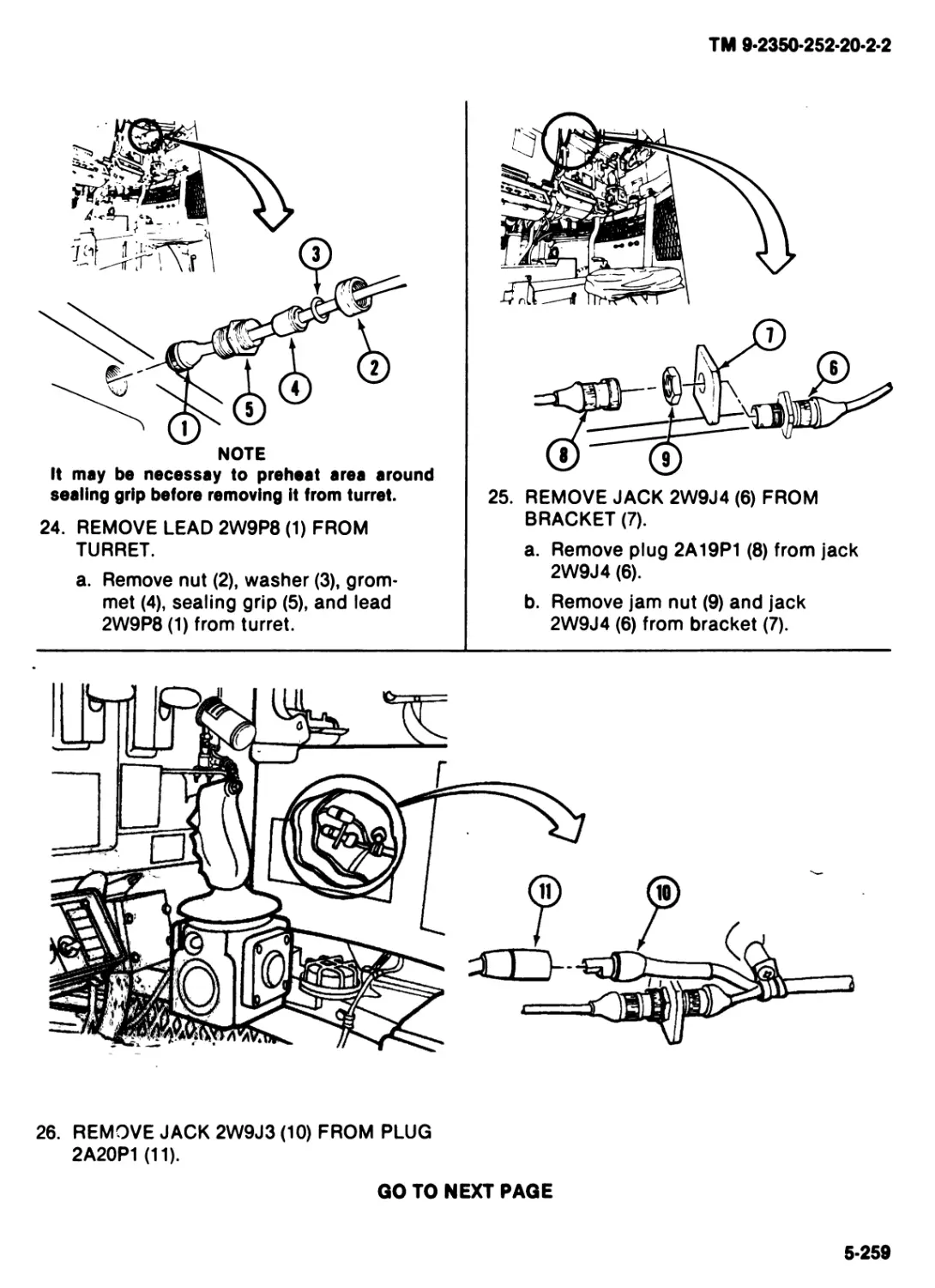
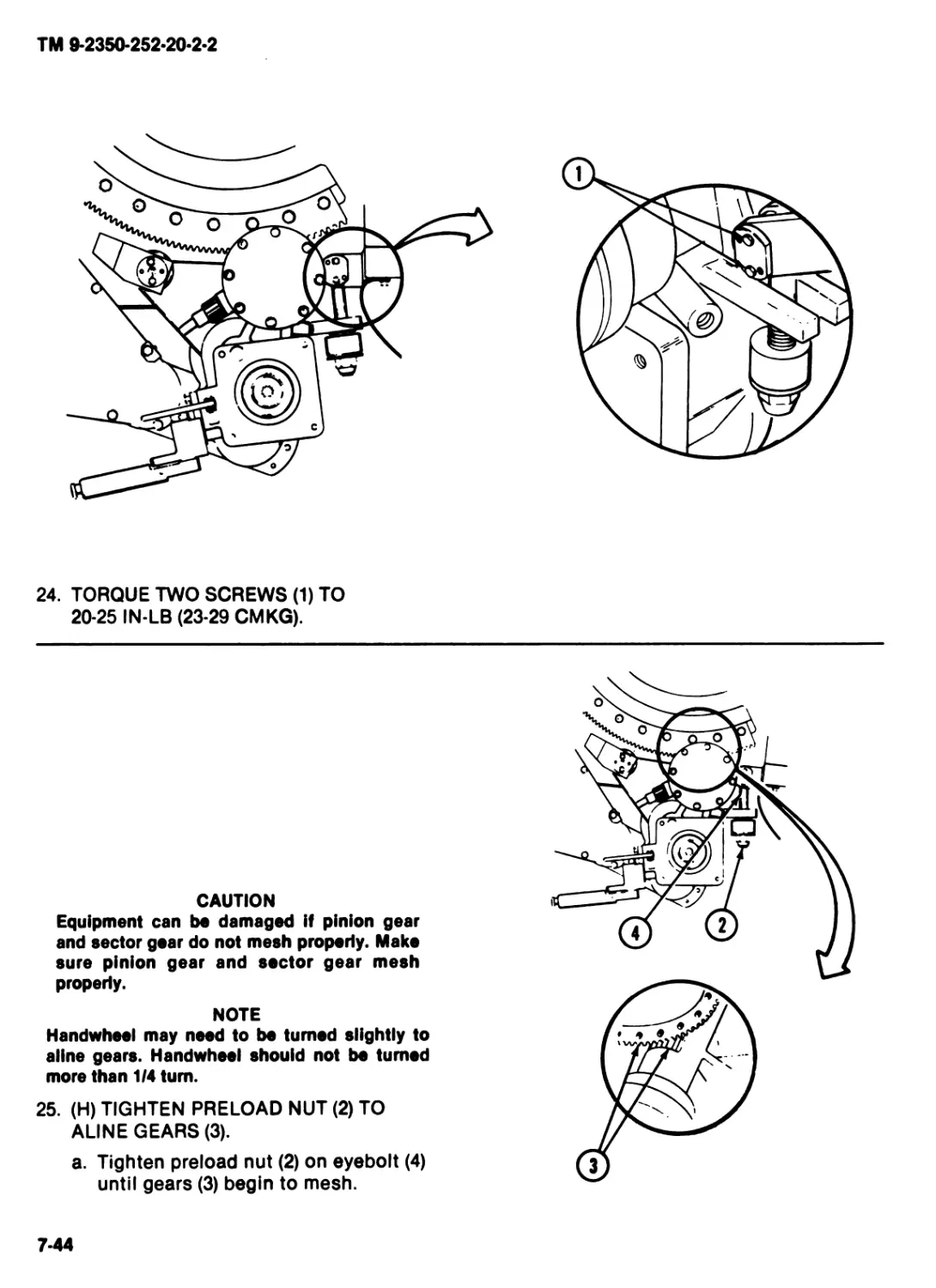
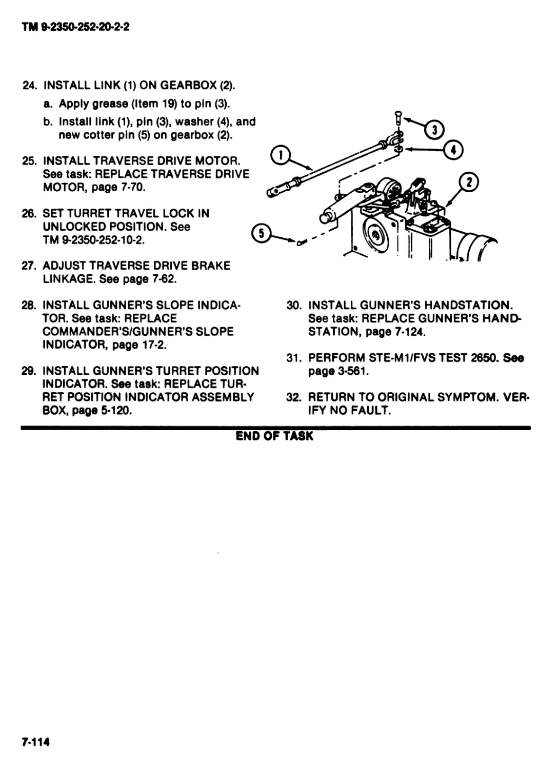
DEPARTMENT OF THE ARMY
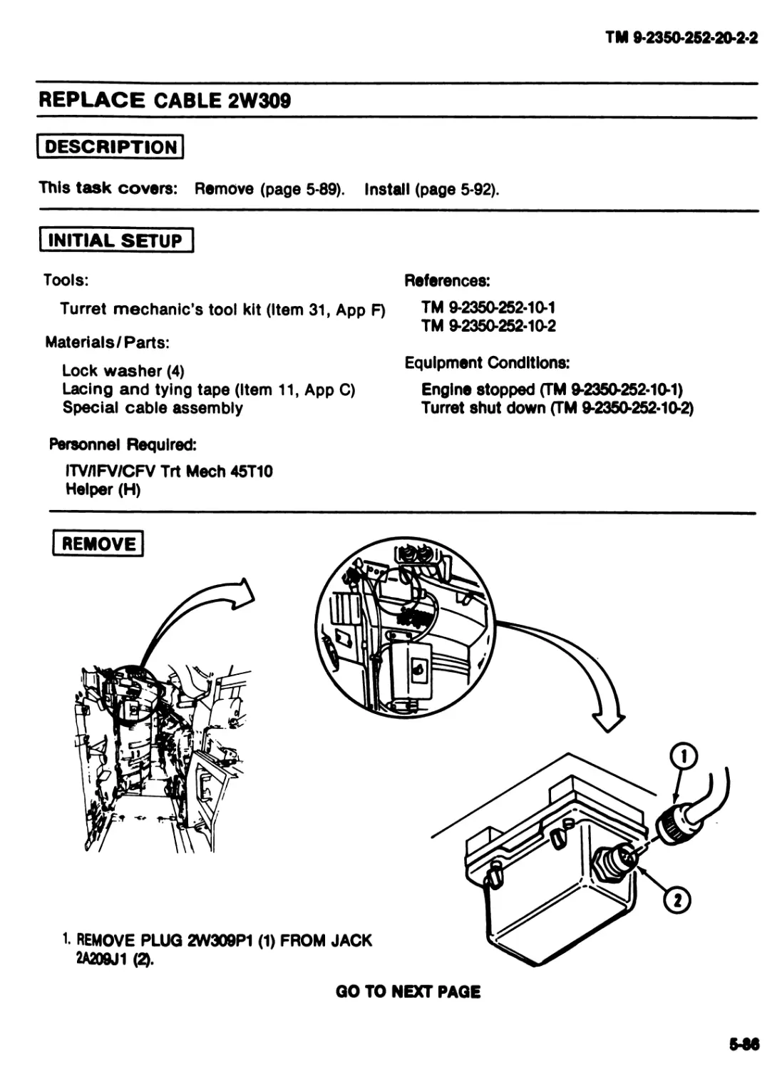
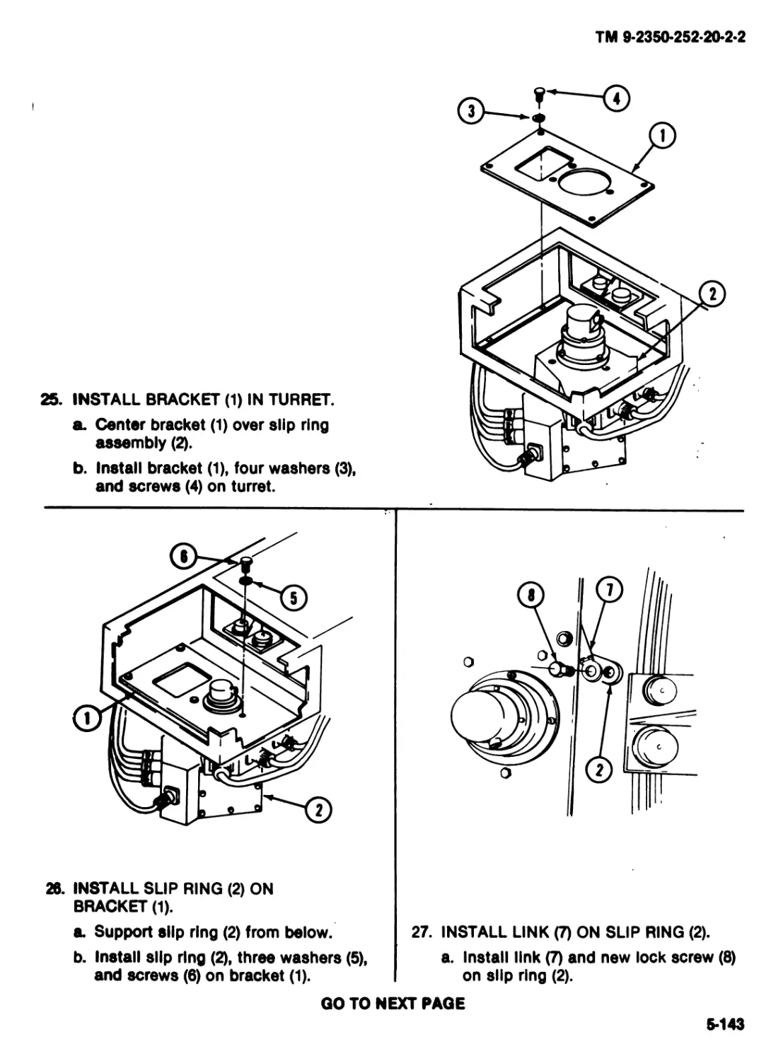
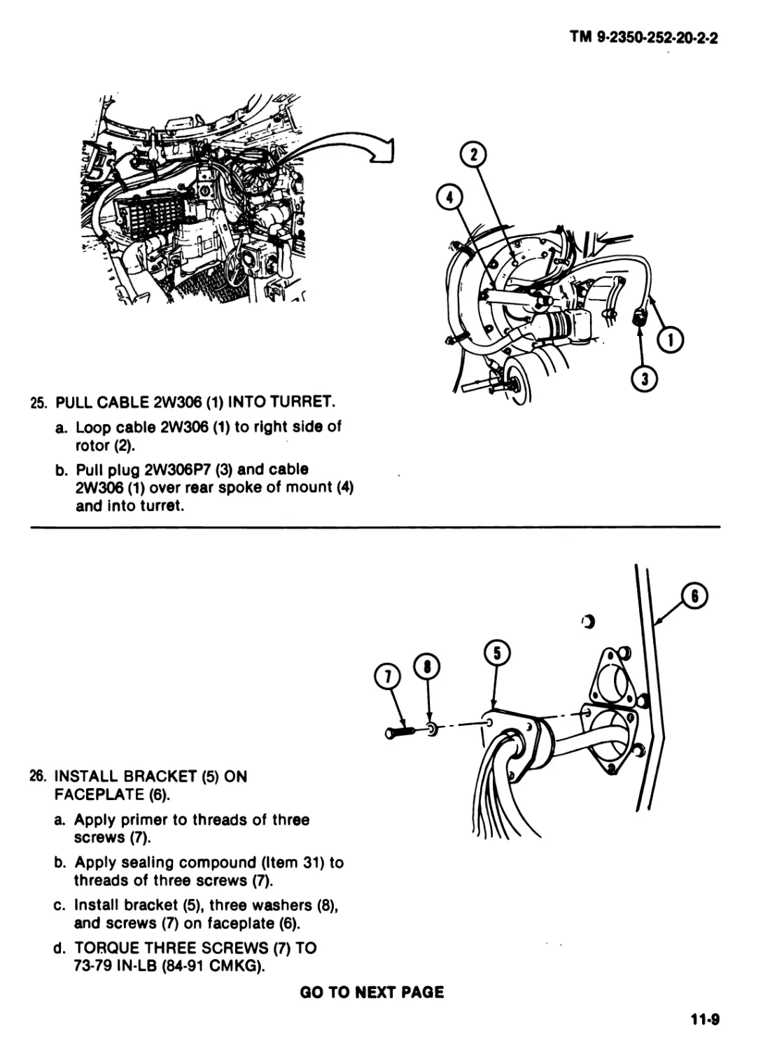
ТМ 9-2350-252-20-2-2
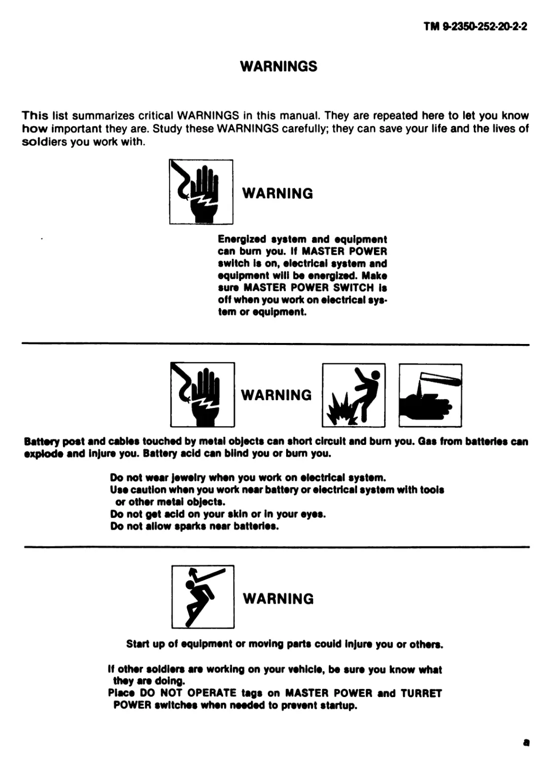
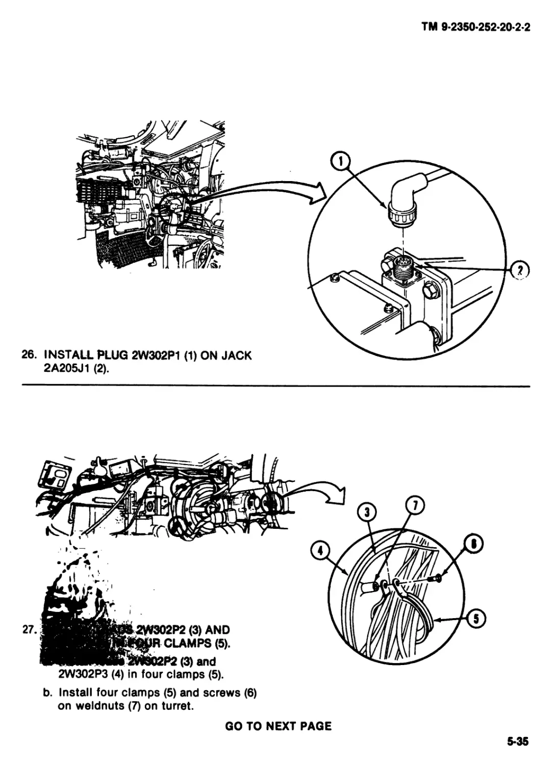
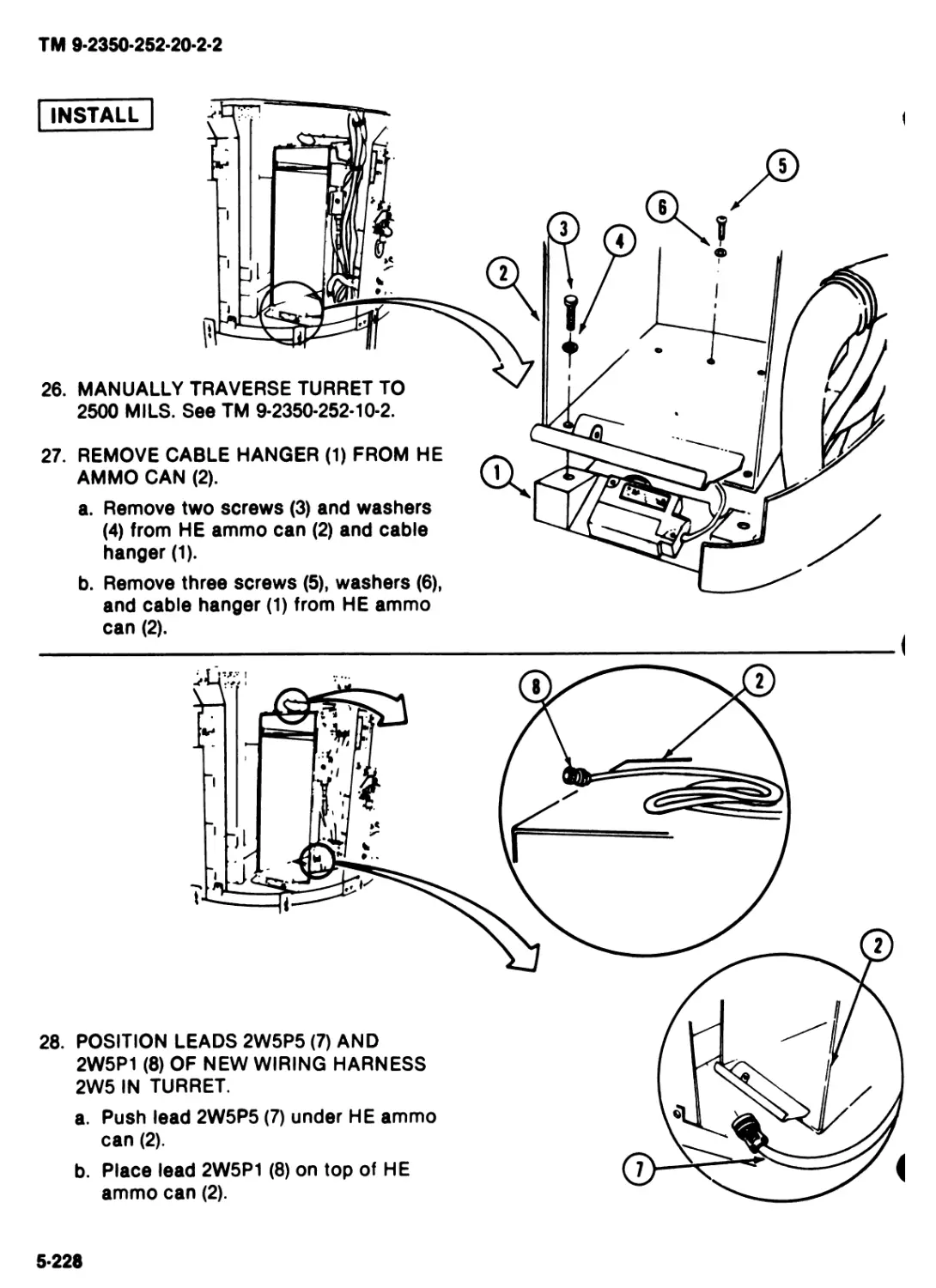
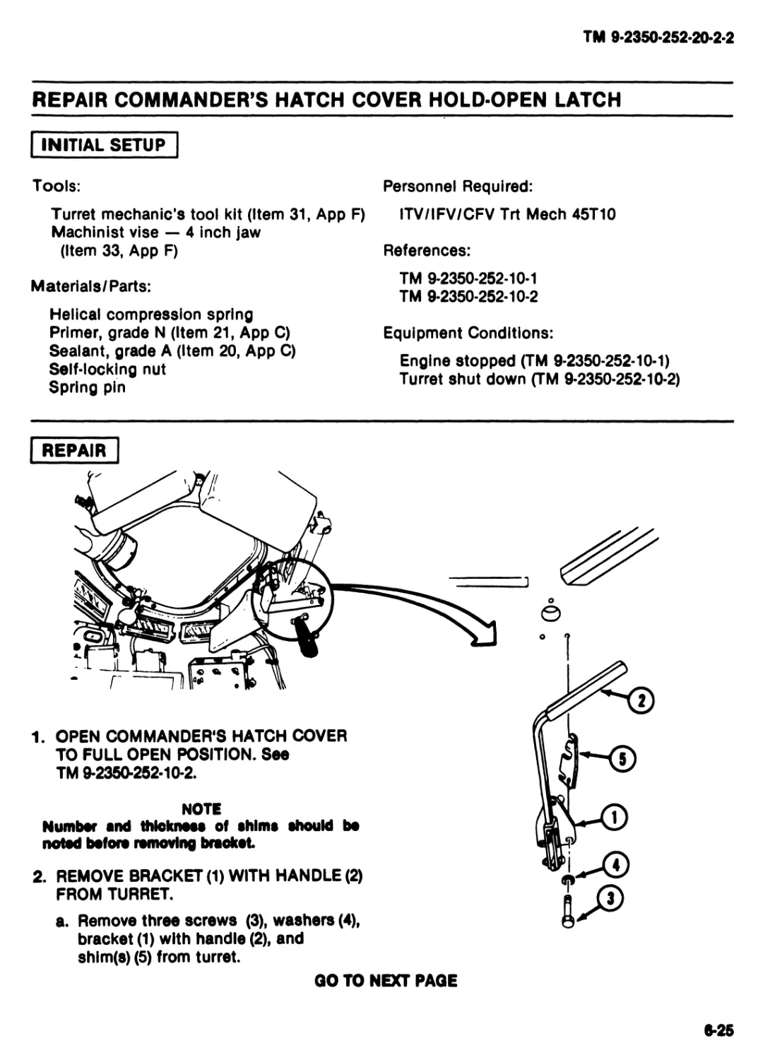
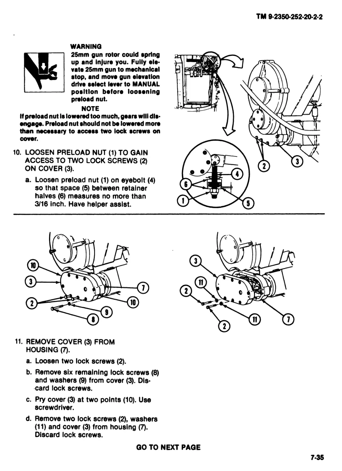
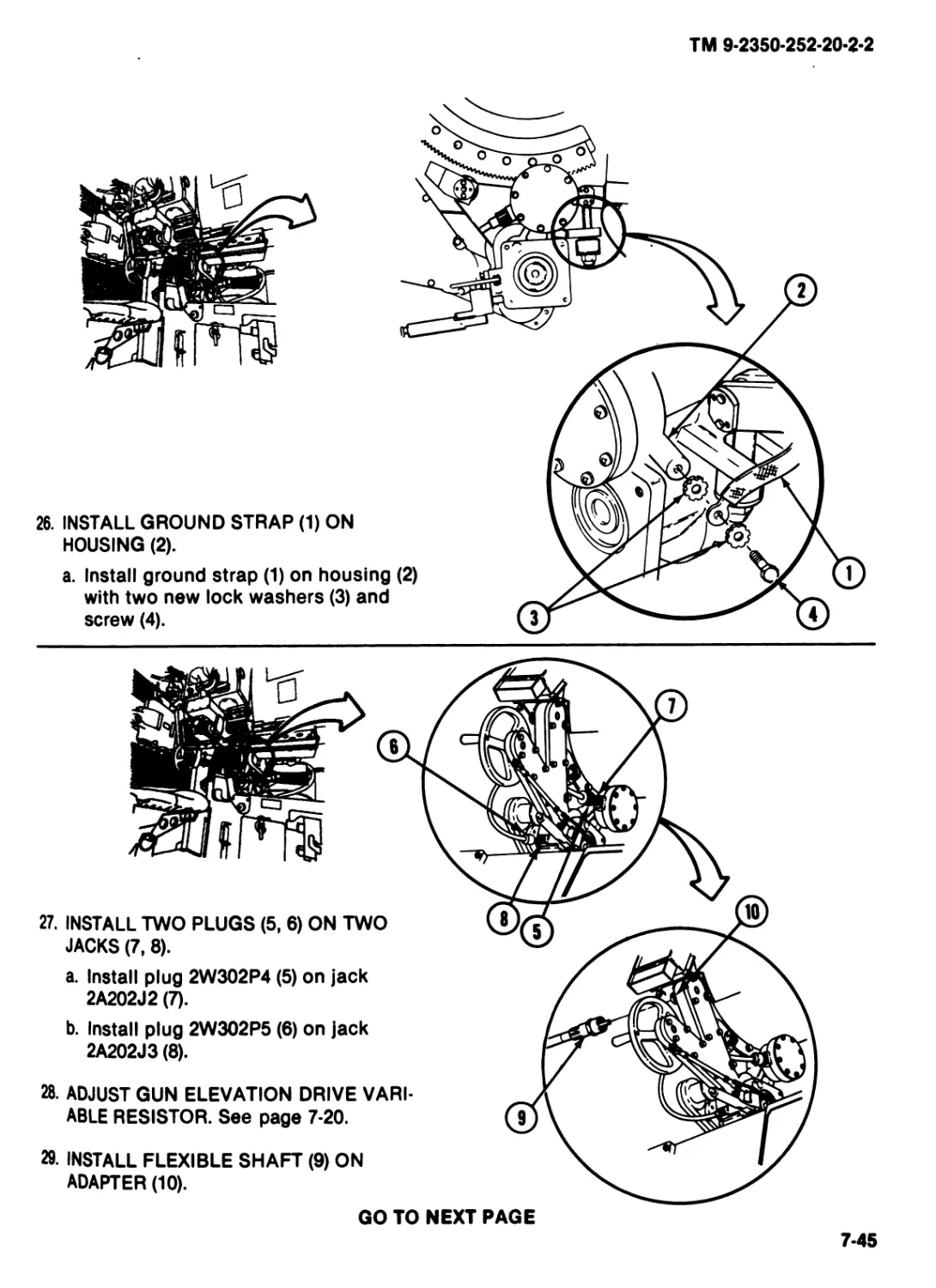
WARNINGS
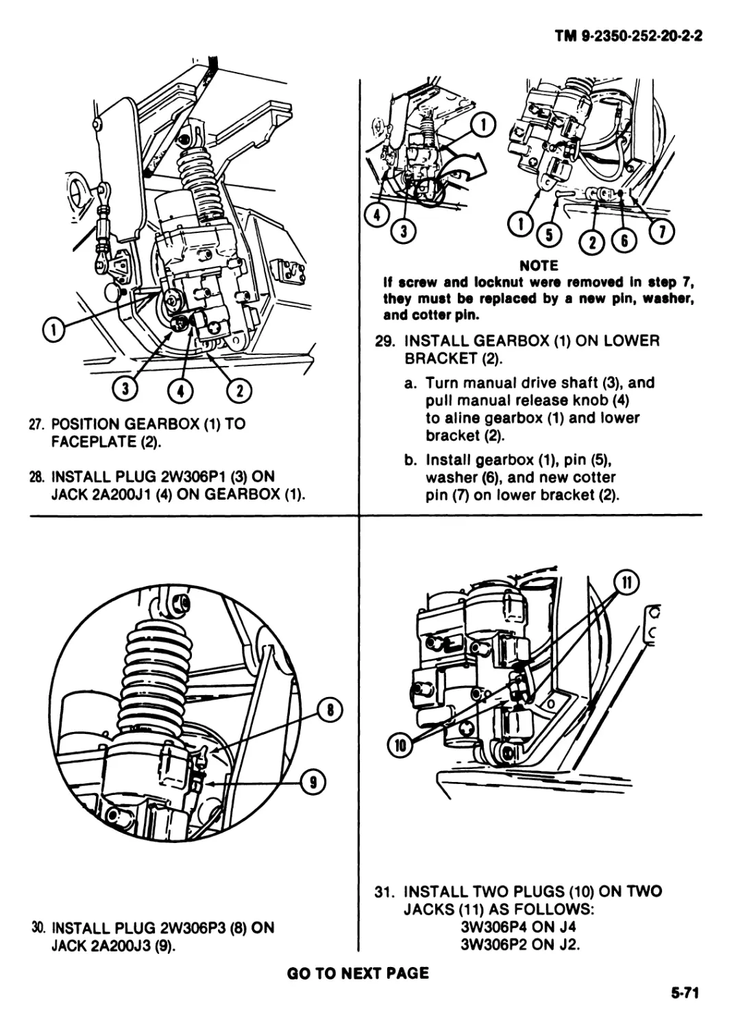
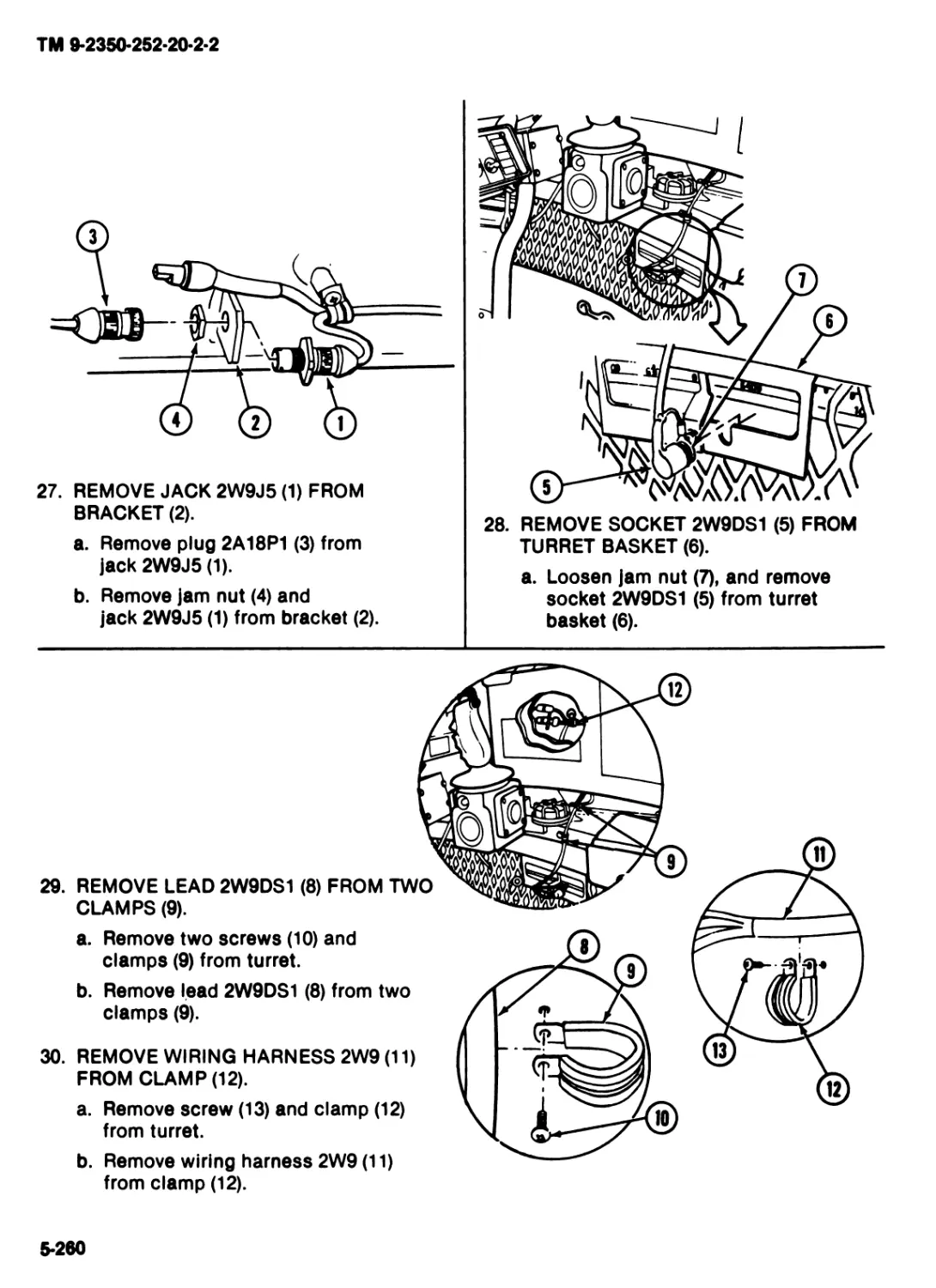
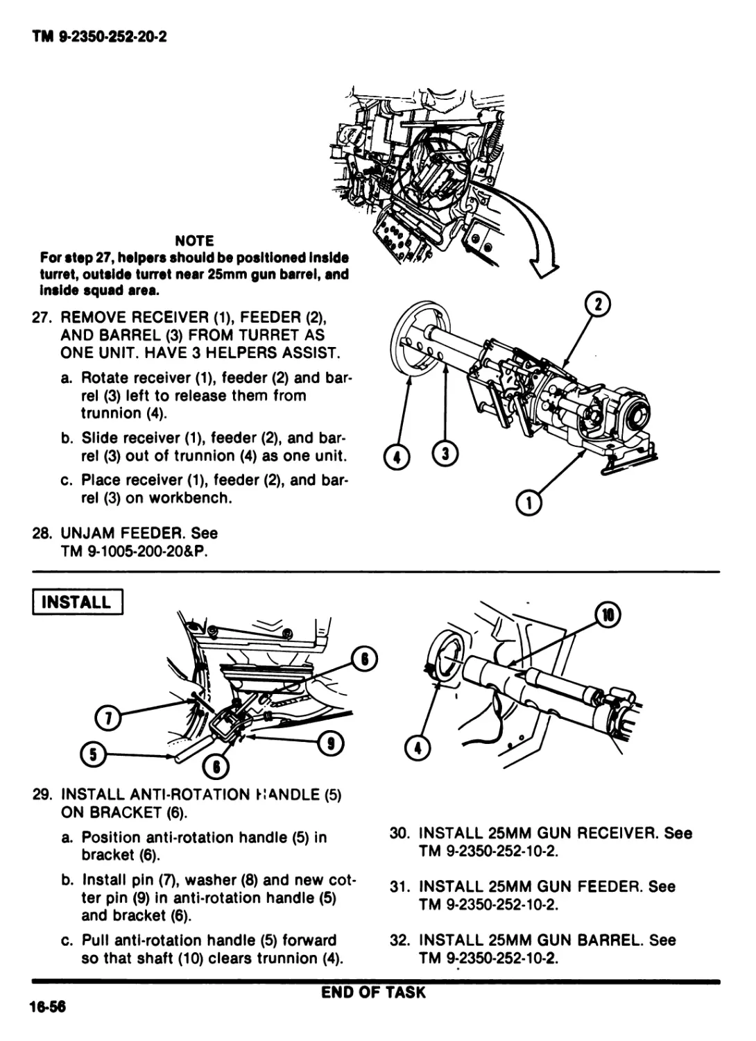
This list summarizes critical WARNINGS in this manual. They are repeated here to let you know
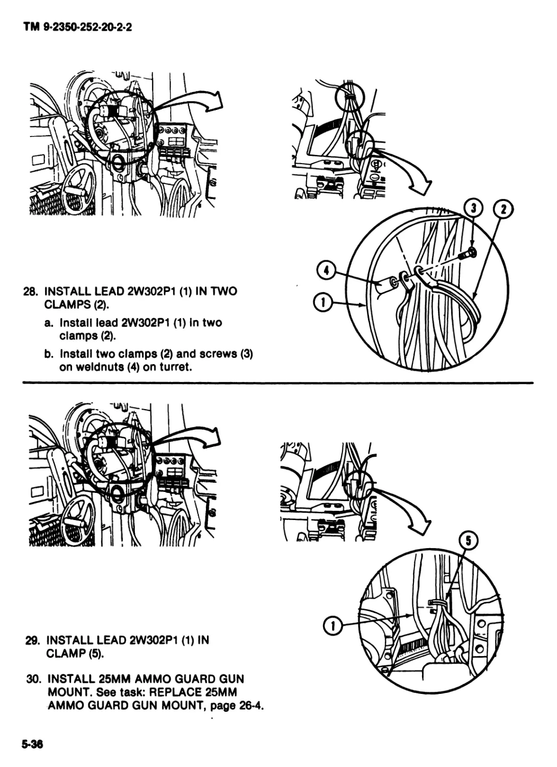
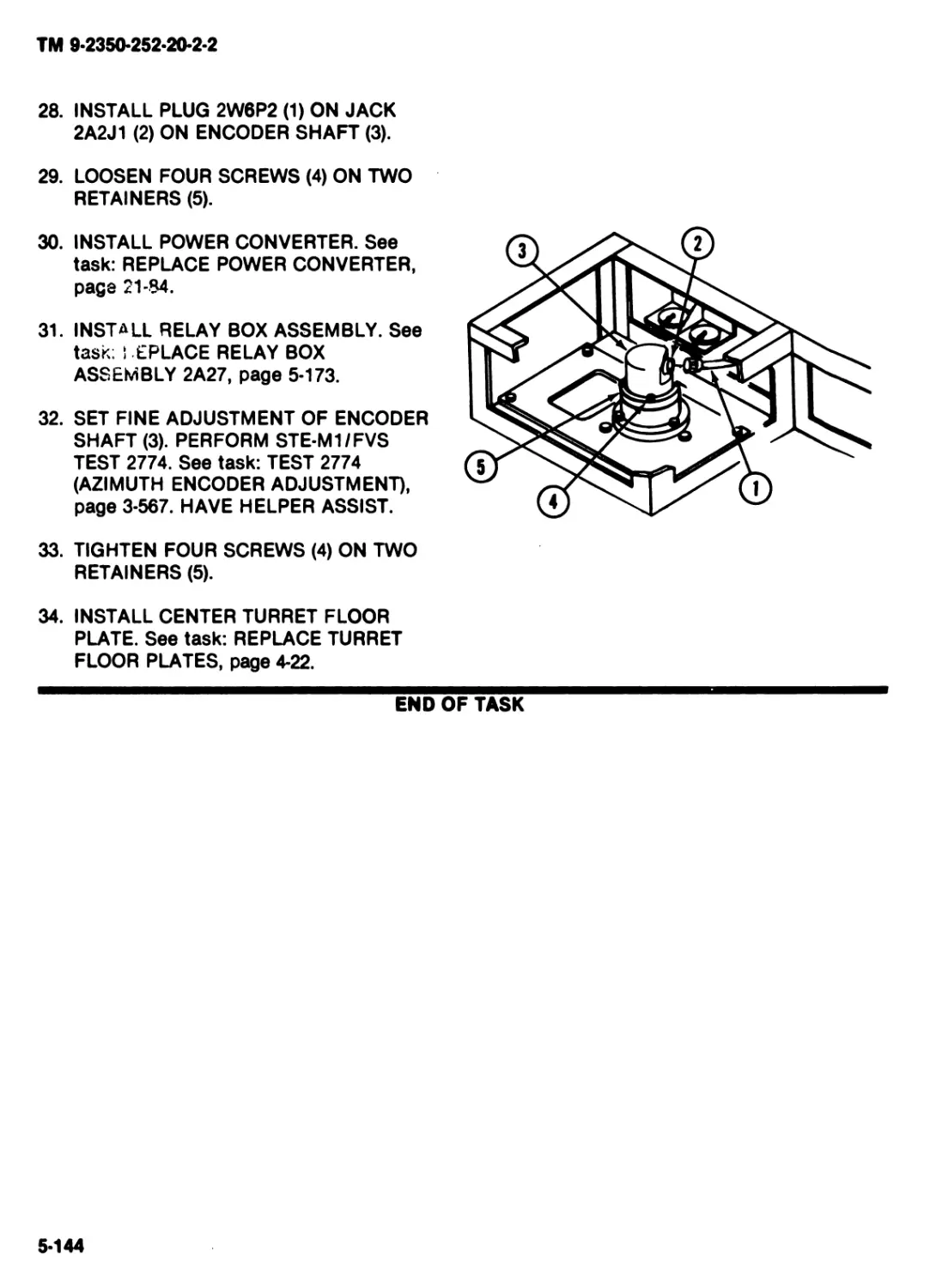
how important they are. Study these WARNINGS carefully; they can save your life and the lives of
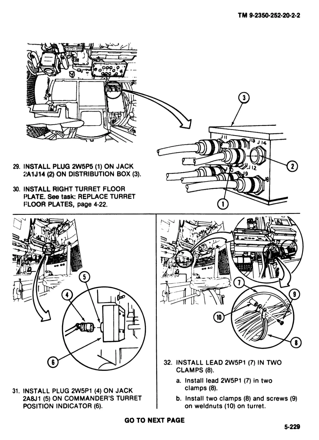
soldiers you work with.
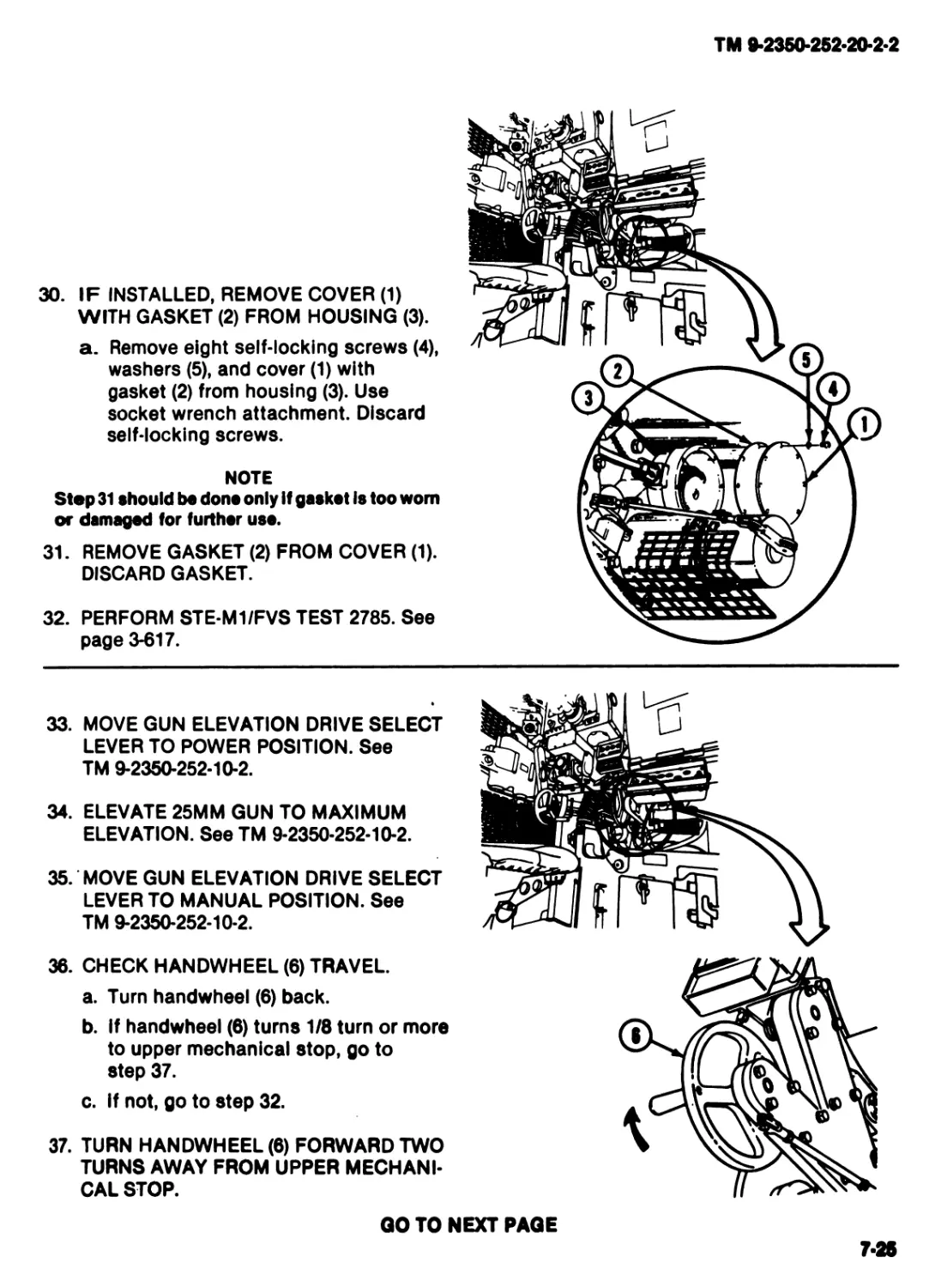
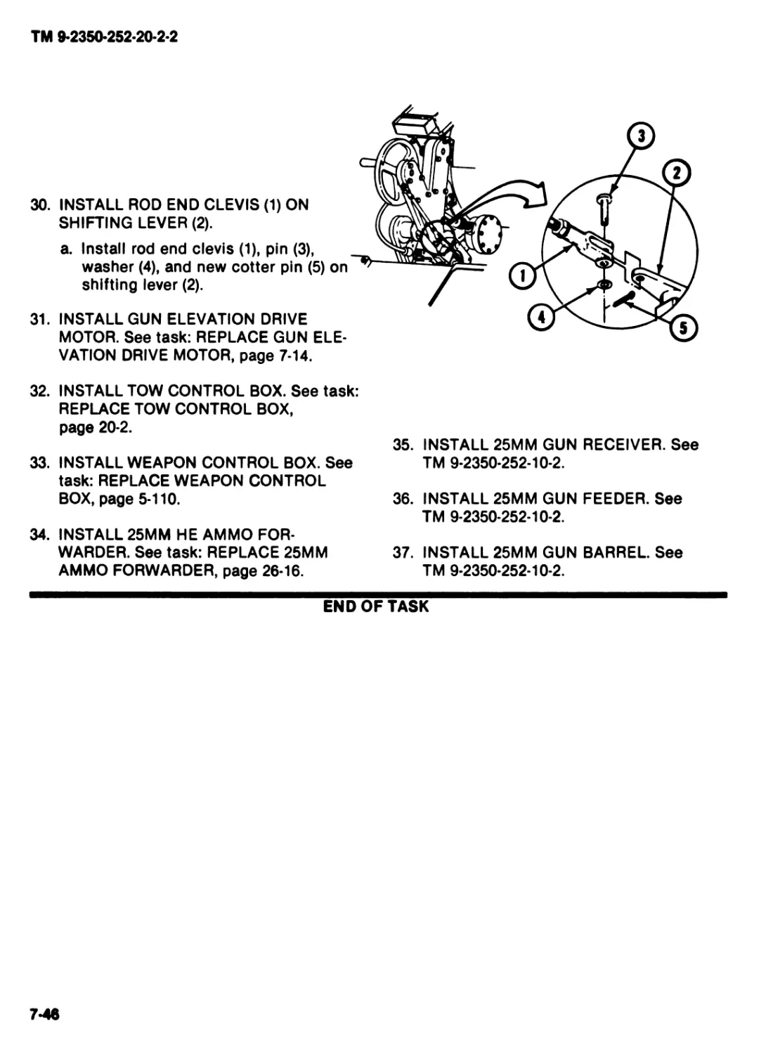
WARNING
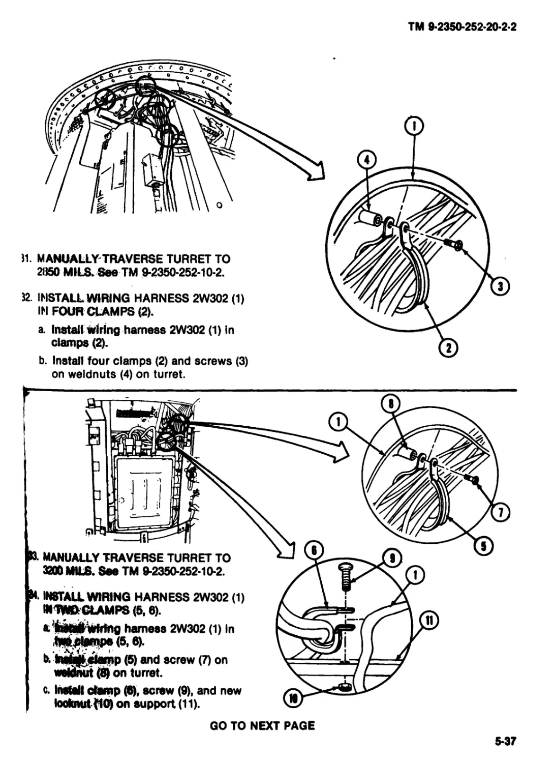
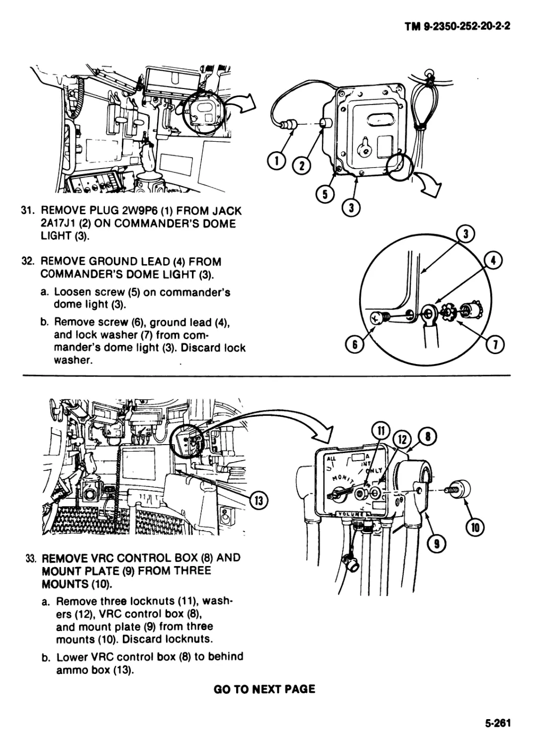
Energized system and equipment
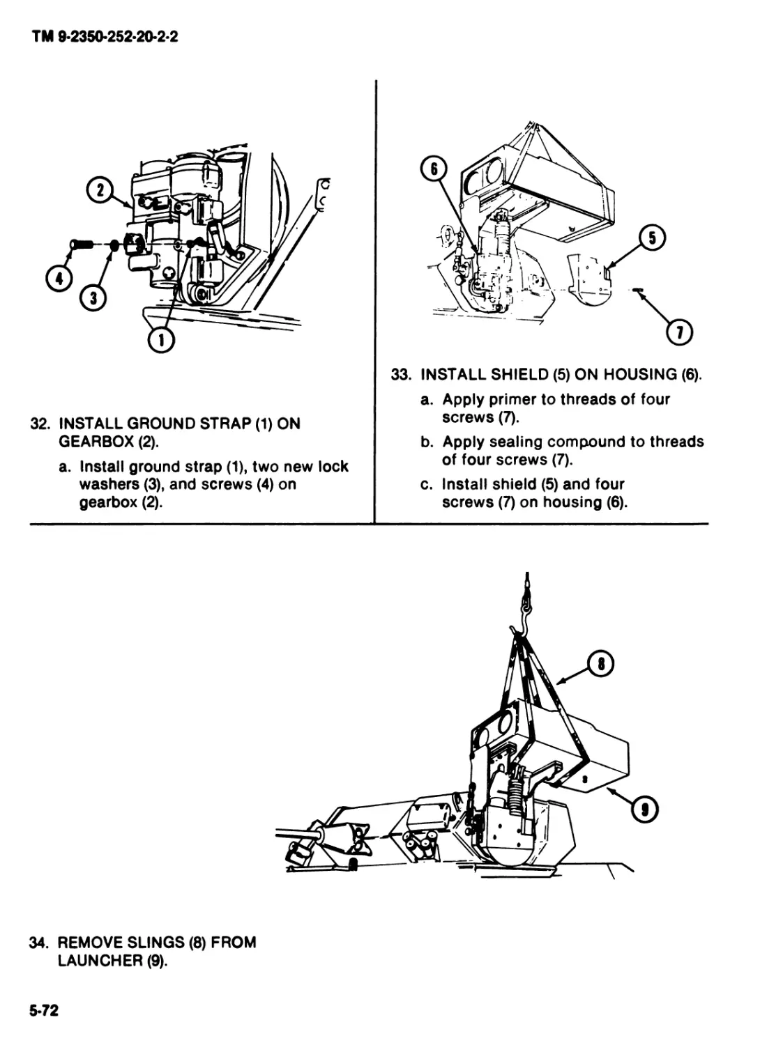
can bum you. If MASTER POWER
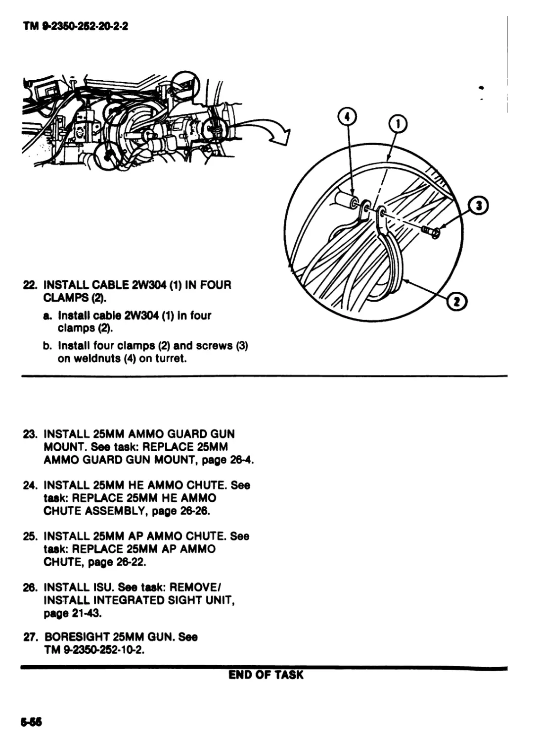
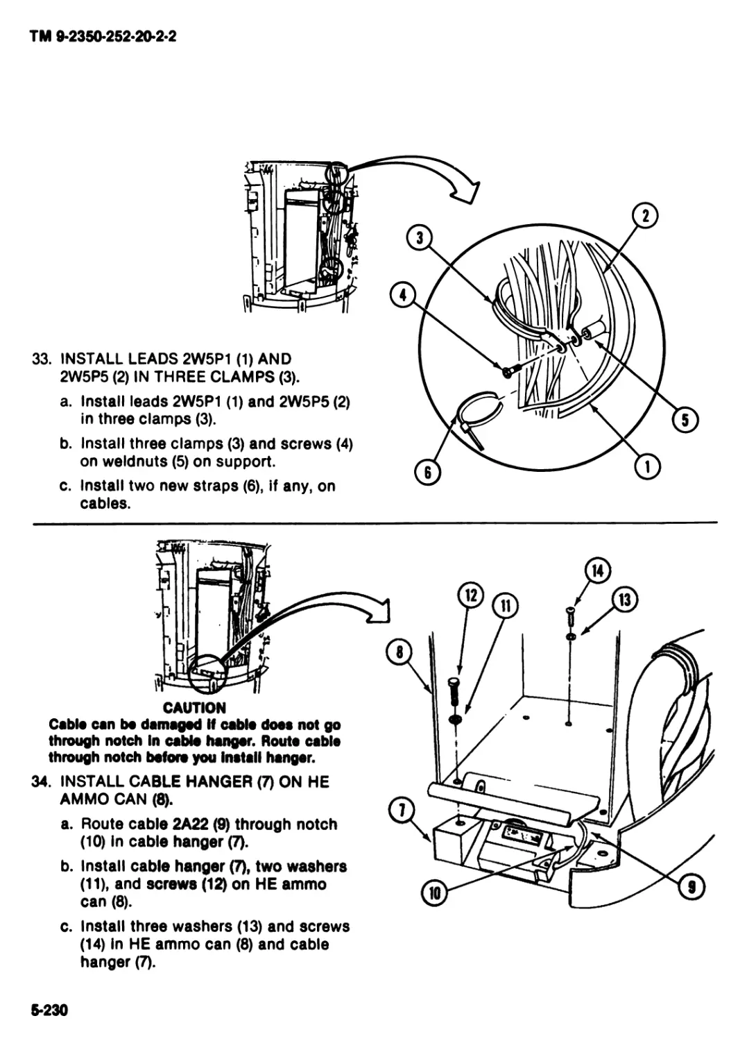
switch is on, electrical system and
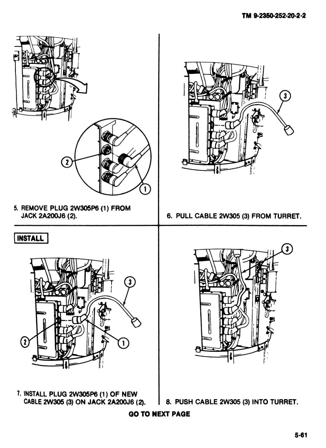
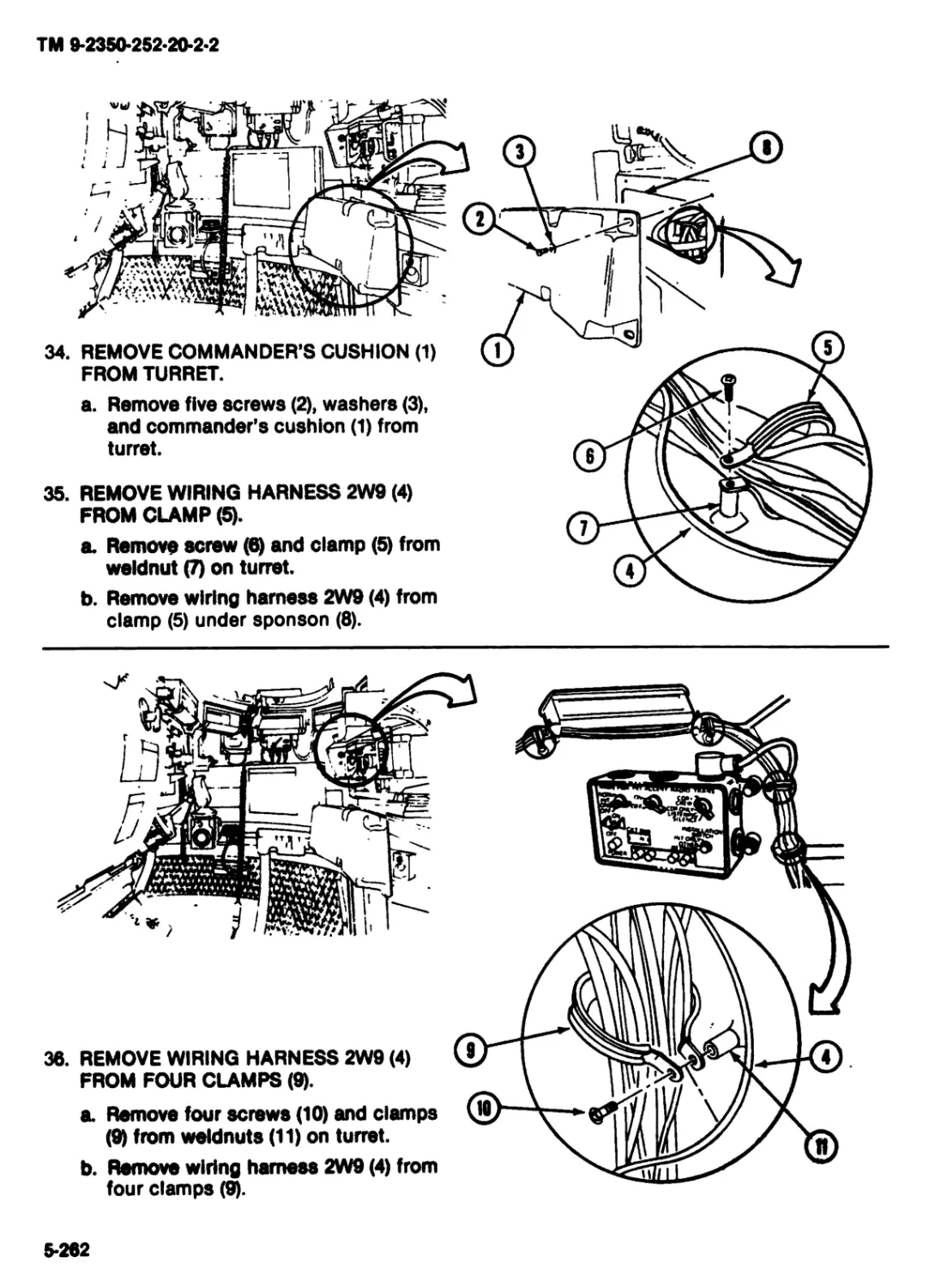
equipment will bo energized. Make
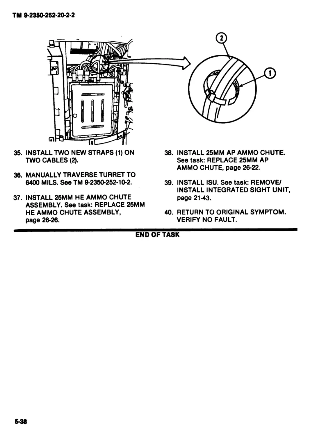
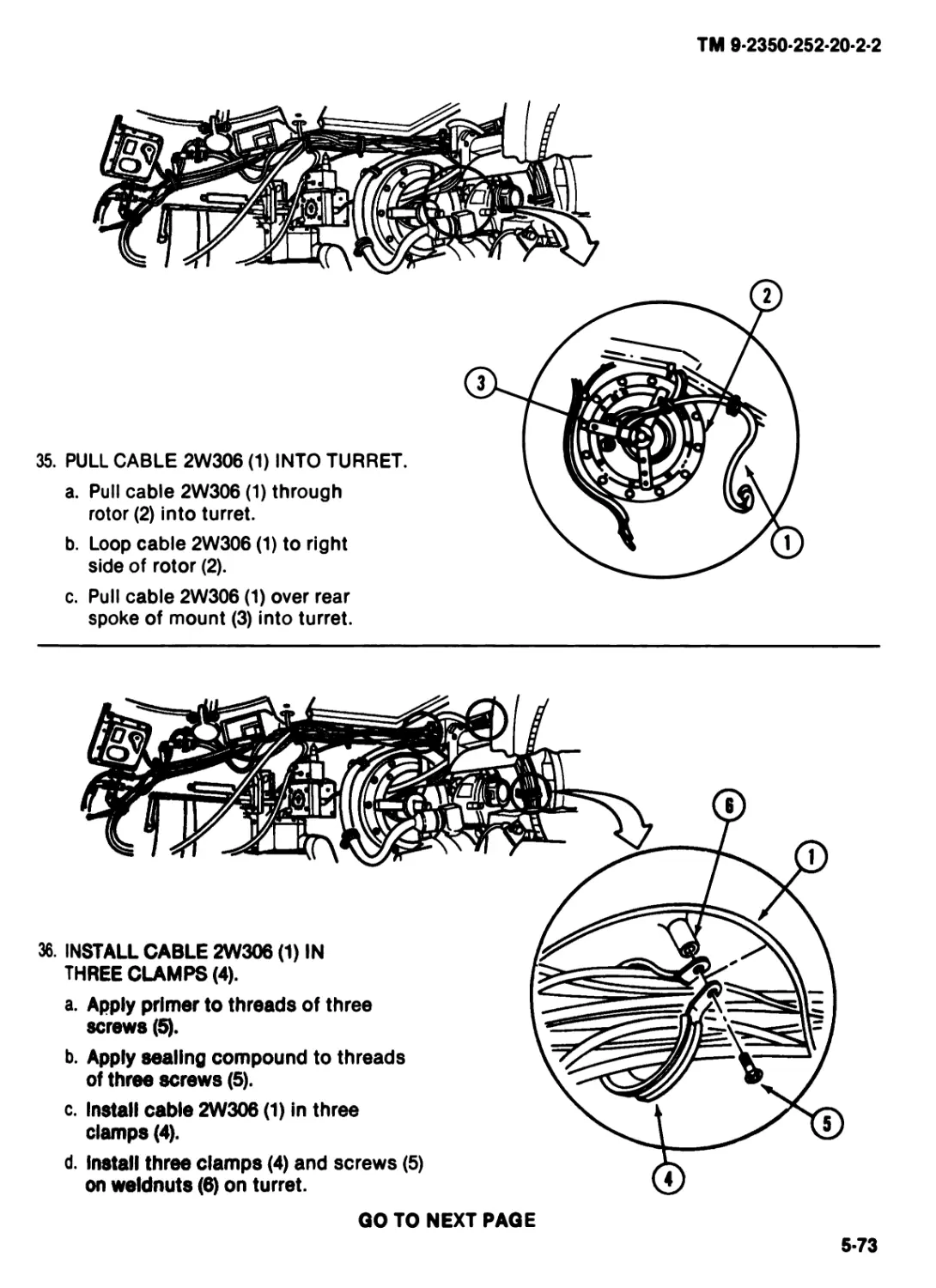
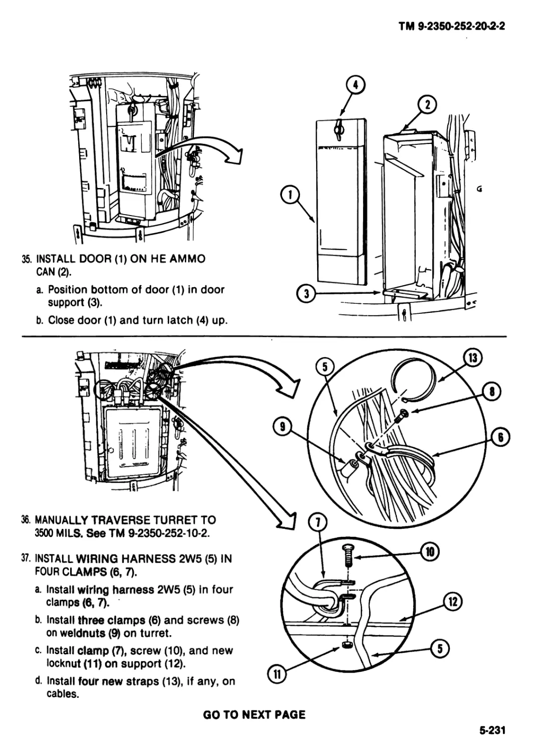
sure MASTER POWER SWITCH Is
off when you work on electrical ays*
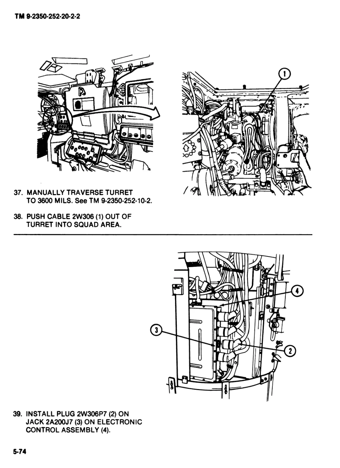
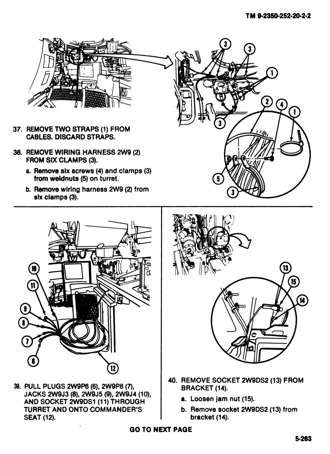
tern or equipment.
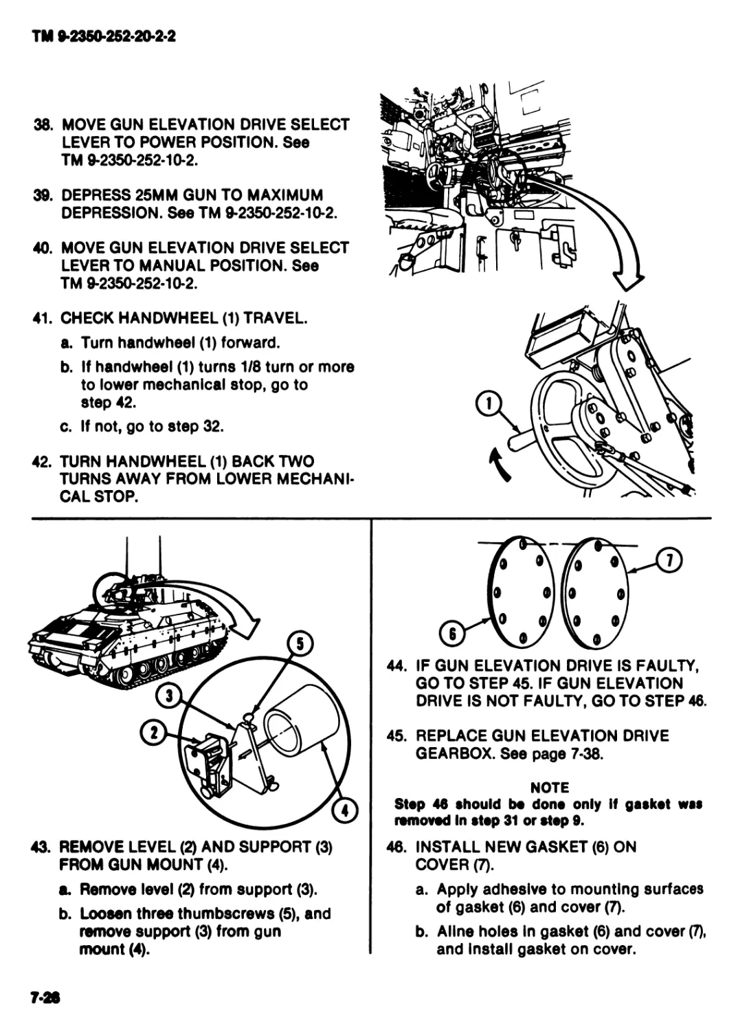
Battery post and cables touched by metal objects can short circuit and bum you. Gas from batteries can
explode and injure you. Battery acid can blind you or bum you.
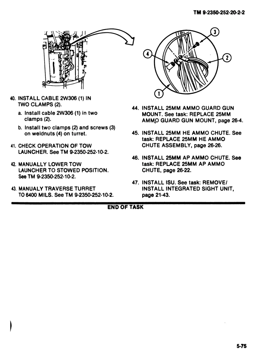
Do not wear Jewelry when you work on electrical system.
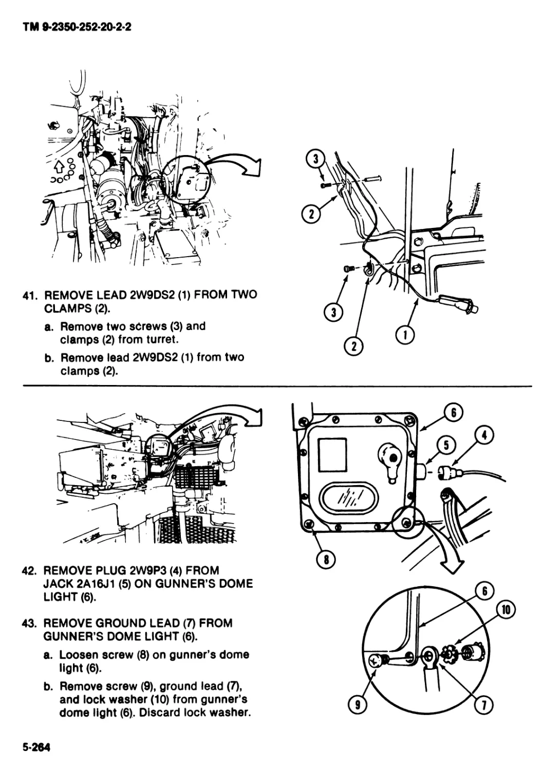
Use caution whon you work noar battery or electrical system with tools
or other metal objects.
Do not get acid on your skin or in your eyos.
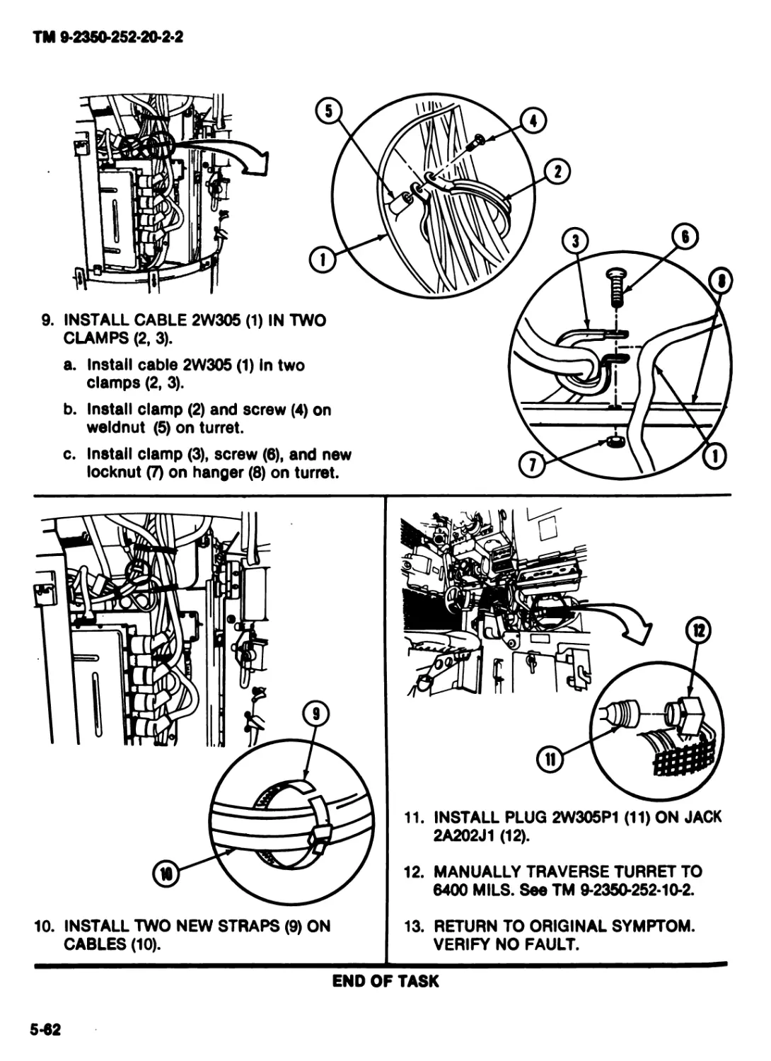
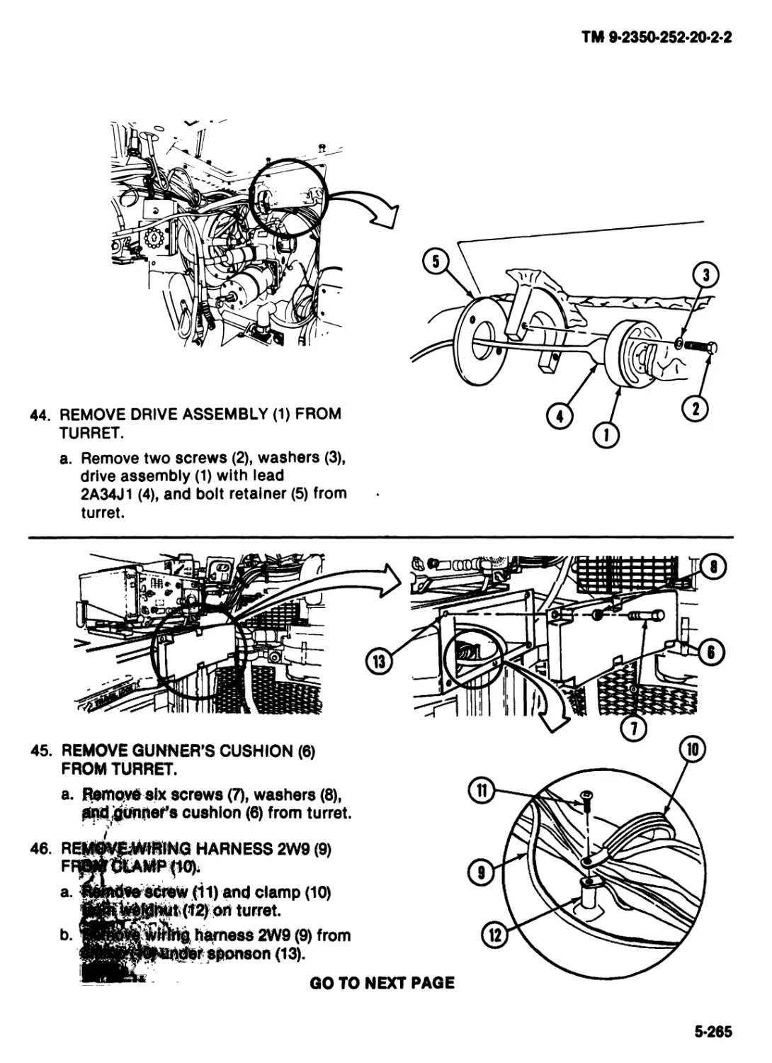
Do not allow sparks noar batteries.
WARNING
Start up of equipment or moving parts could Injure you or others.
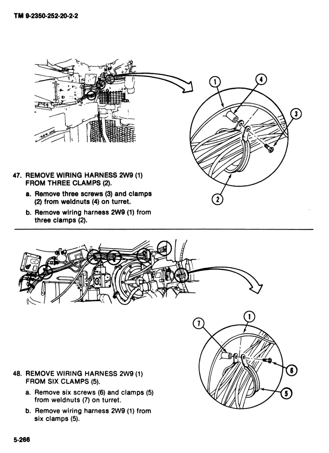
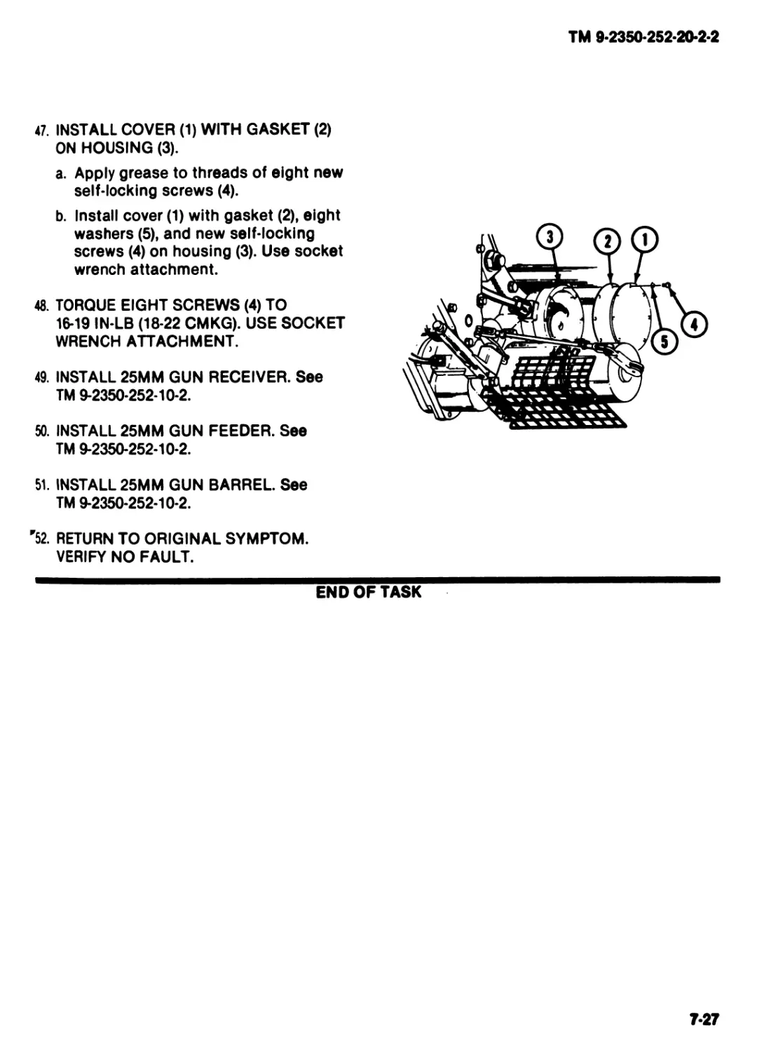
If other soldiers are working on your vehicle, be sure you know what
they are doing.
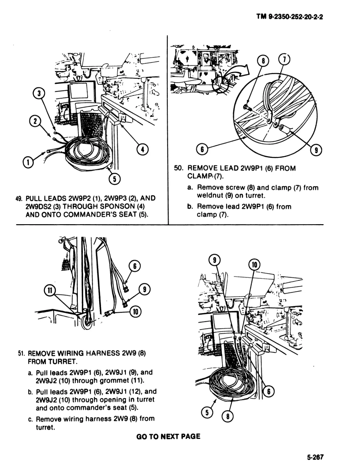
Place DO NOT OPERATE tags on MASTER POWER and TURRET
POWER switches when needed to prevent startup.
ТМ 9-2350-252-20-2-2
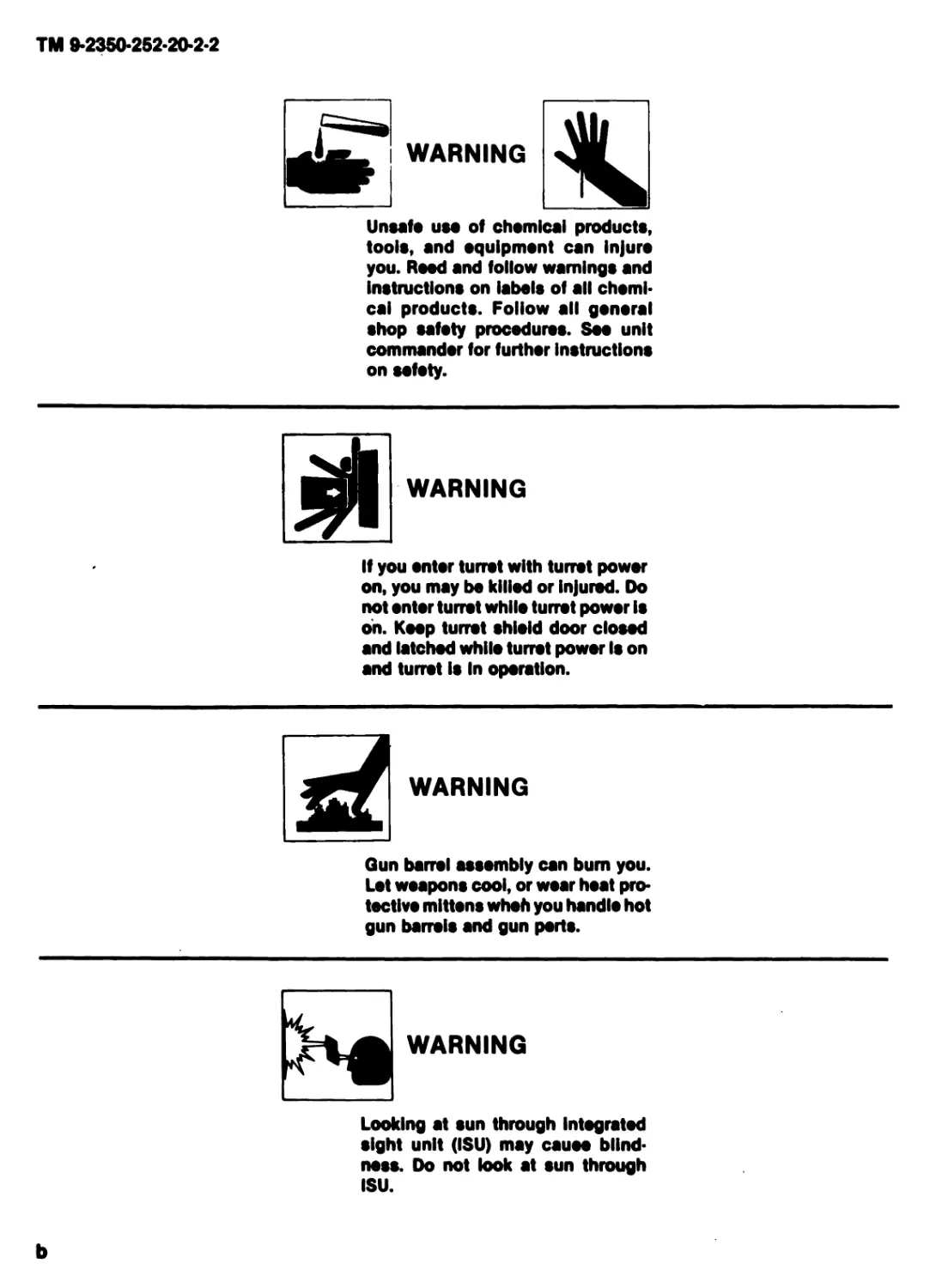
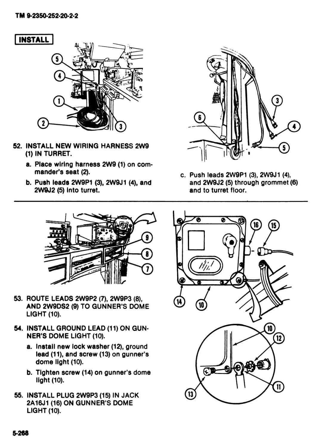
WARNING
Unsafe use of chemical products,
tools, and equipment can injure
you. Reed and follow warnings and
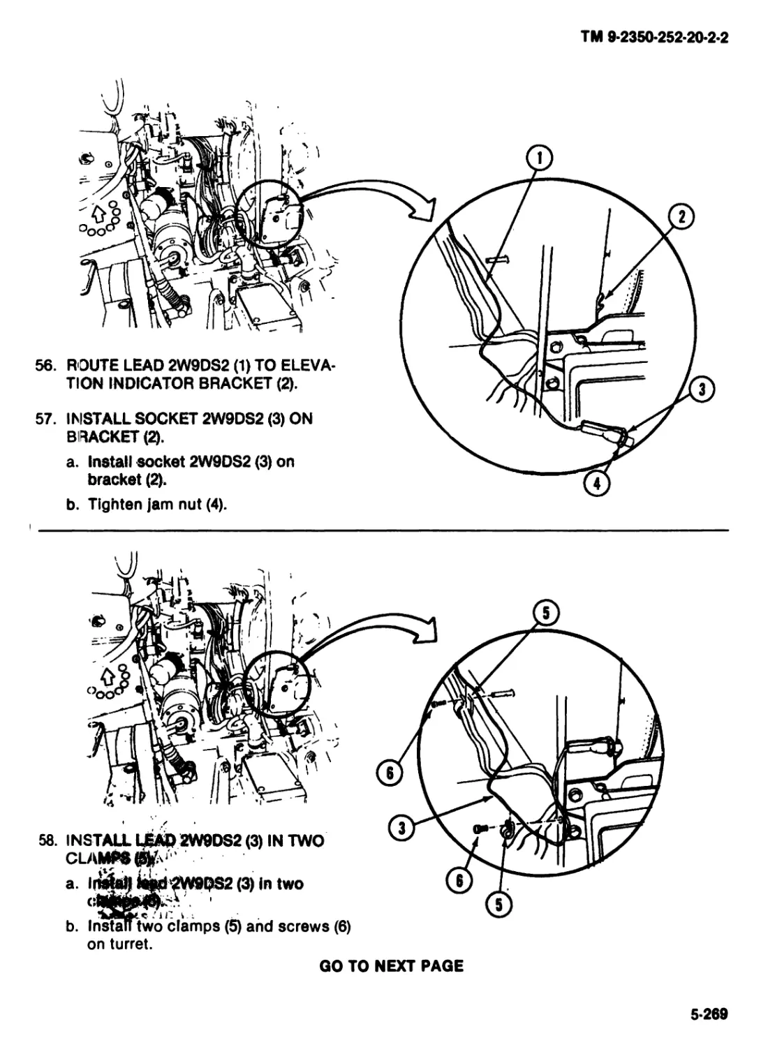
instructions on labels of all chemi-
cal products. Follow all general
shop safety procedures. Soo unit
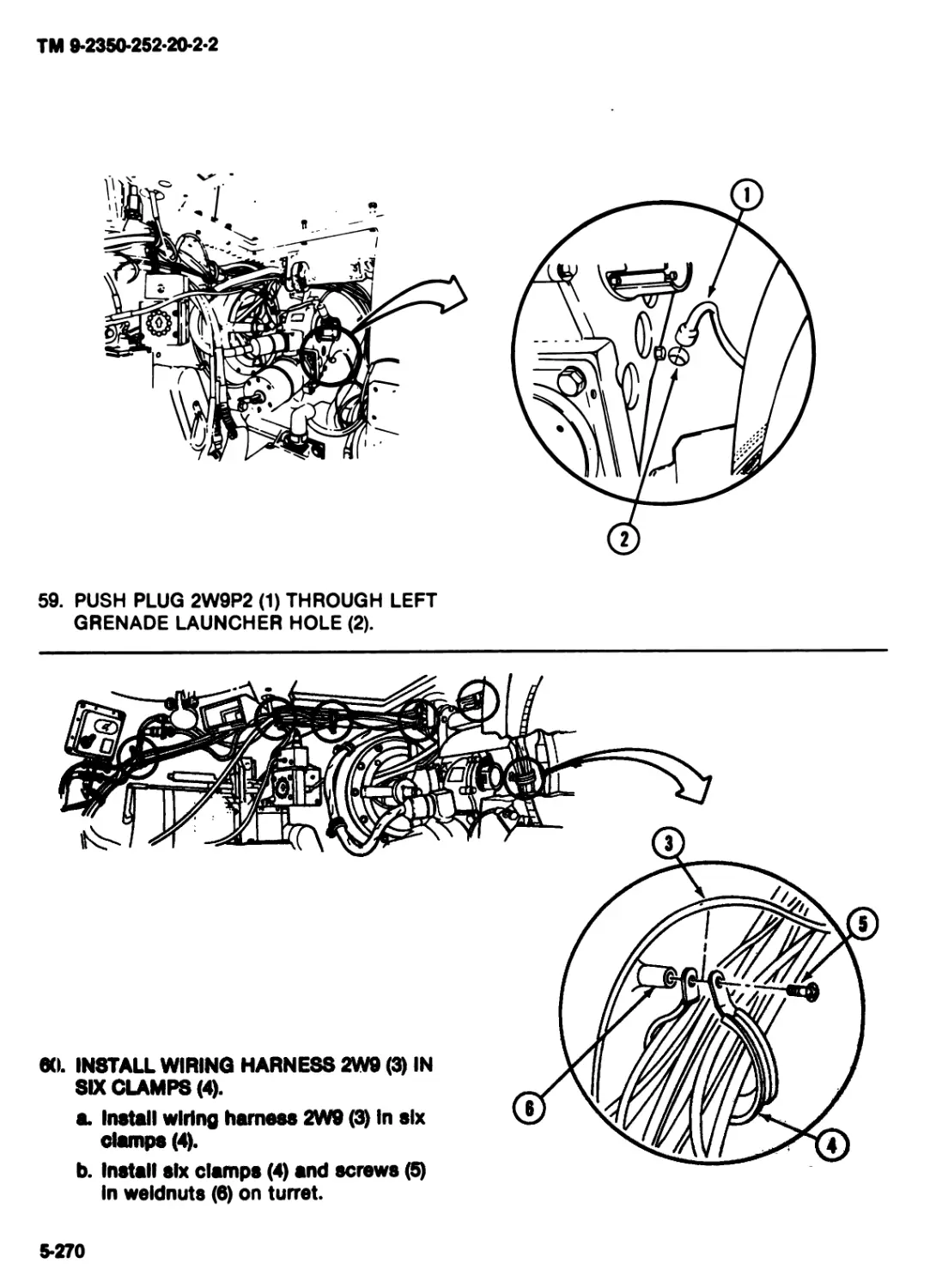
commander for further instructions
on sofoty.
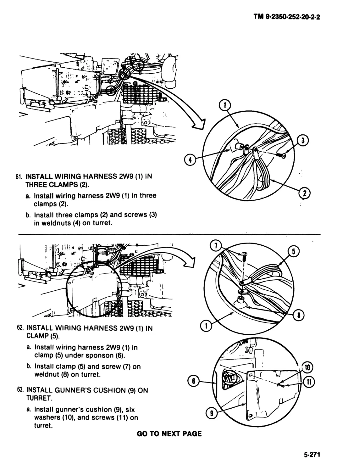
WARNING
If you ontor turret with turret power
on, you may be killed or injured. Do
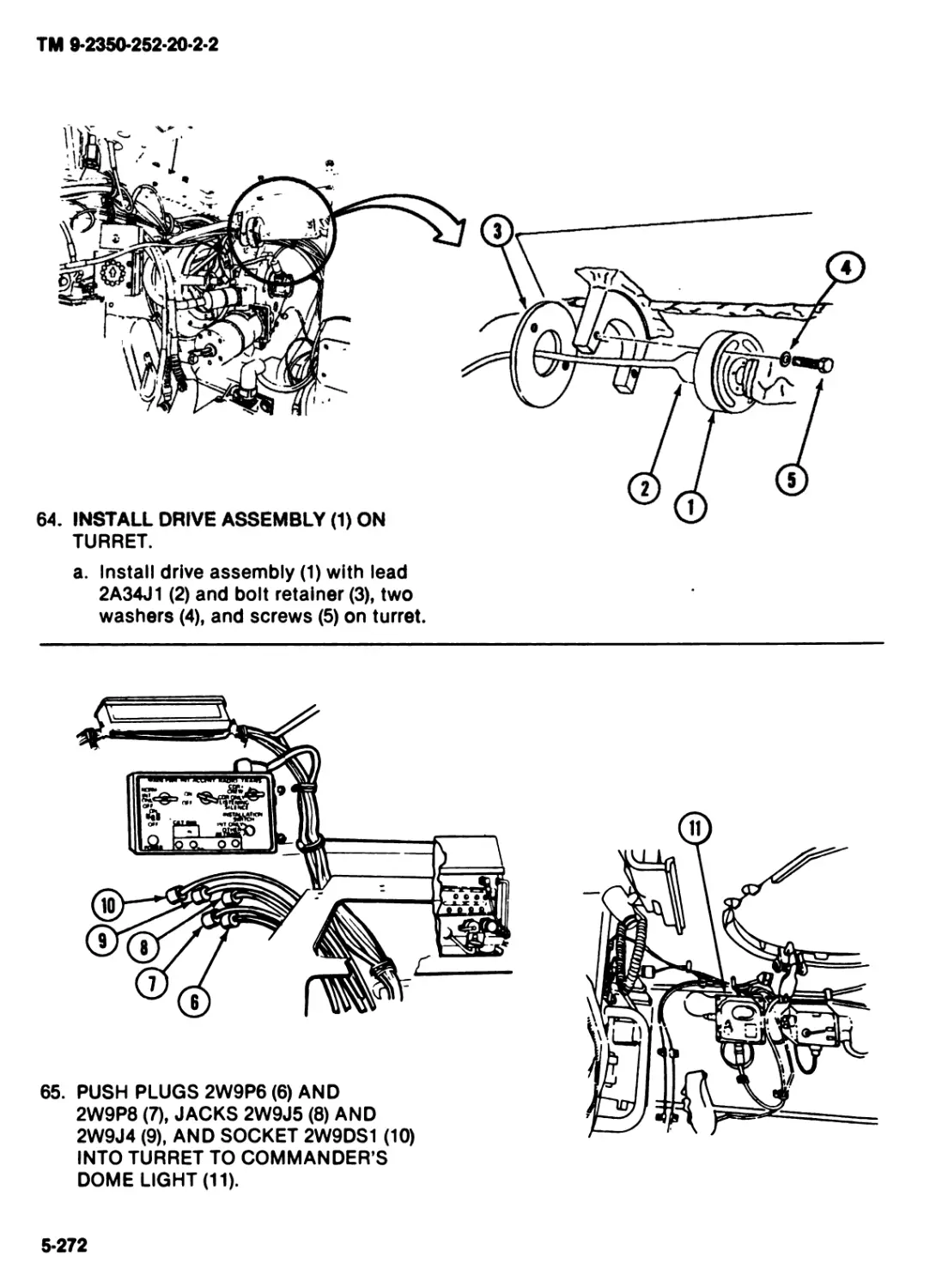
not ontor turret while turret power is
on. Koop turret shield door closed
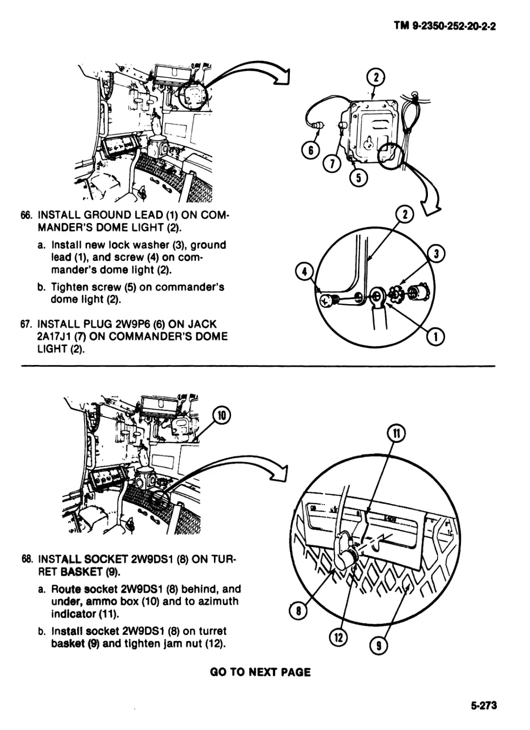
and latched while turret power Is on
and turret is In operation.
WARNING
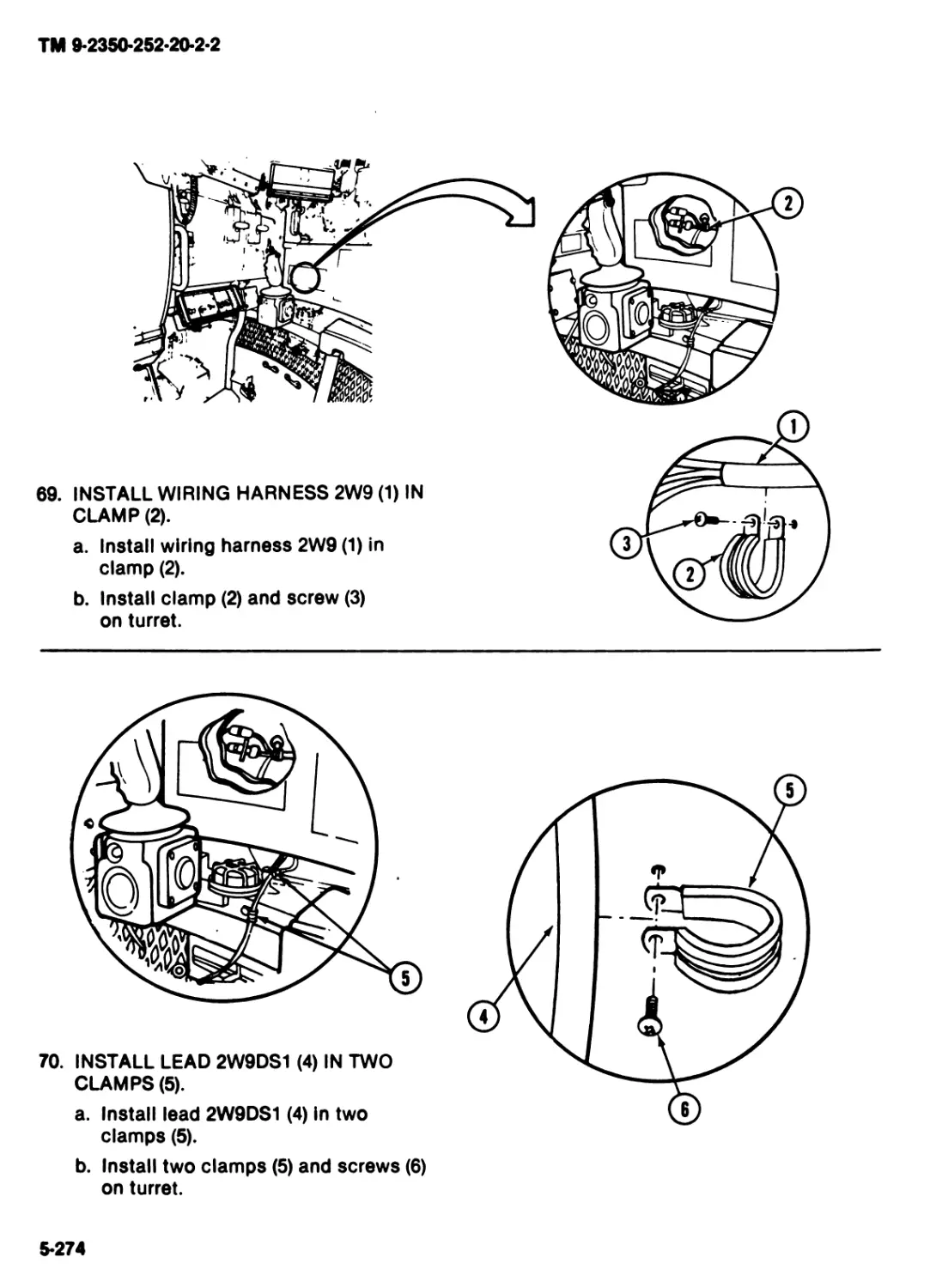
Gun barrel assembly can bum you.
Lot weapons cool, or woar host pro-
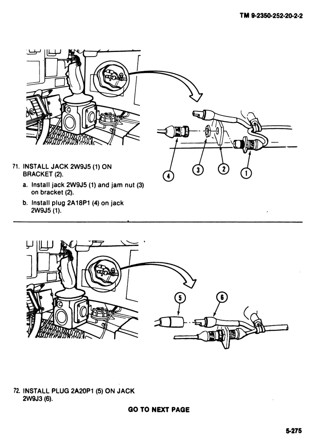
tective mittons wheh you handle hot
gun barrels and gun ports.
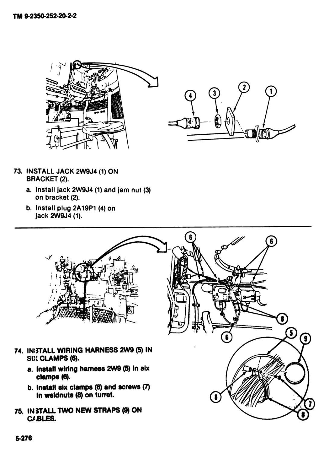
WARNING
Looking at sun through Integrated
sight unit (ISU) may cauoo blind-
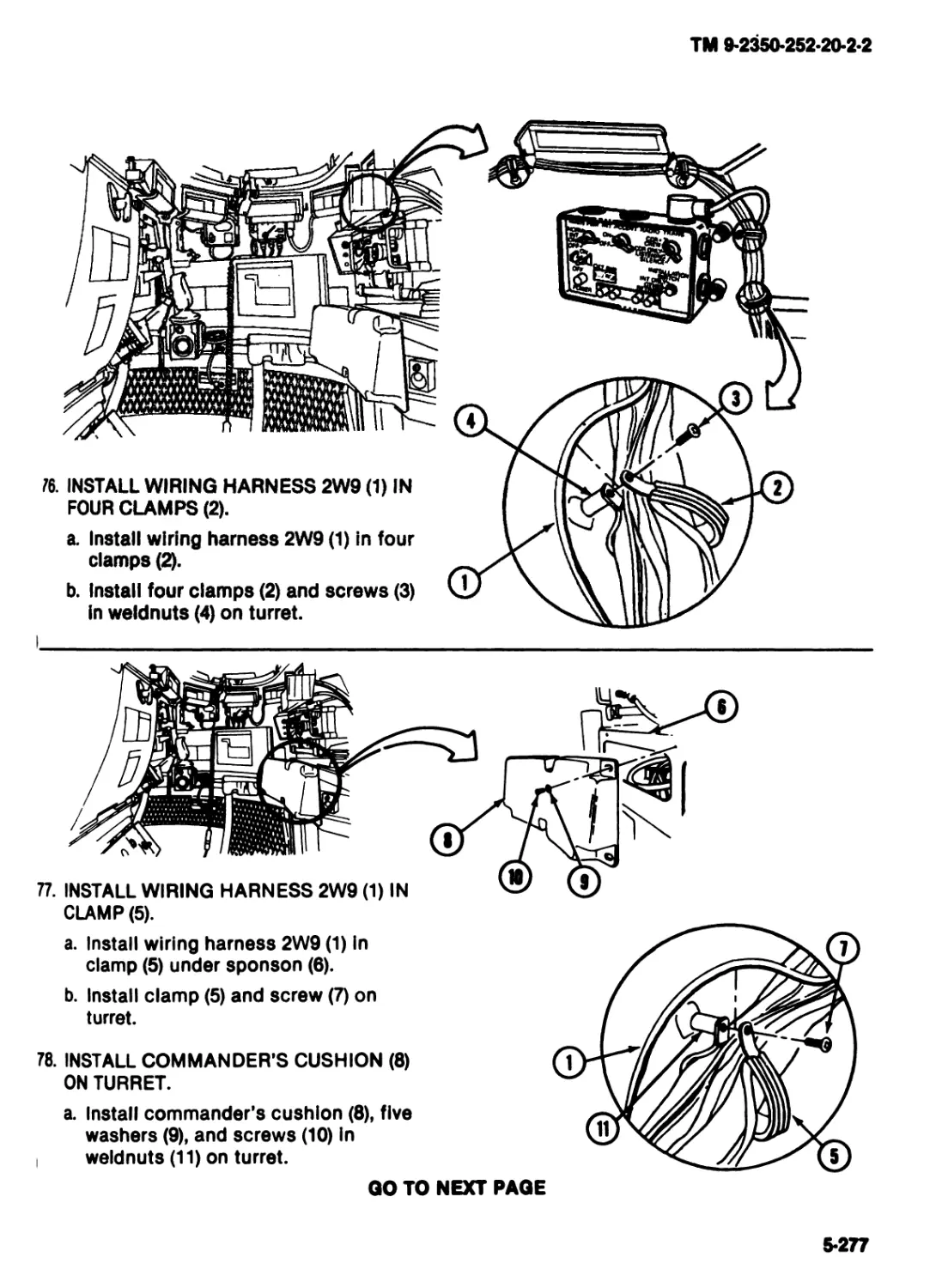
ness. Do not look at sun through
ISU.
ТМ 9-2350-252-20-2-2
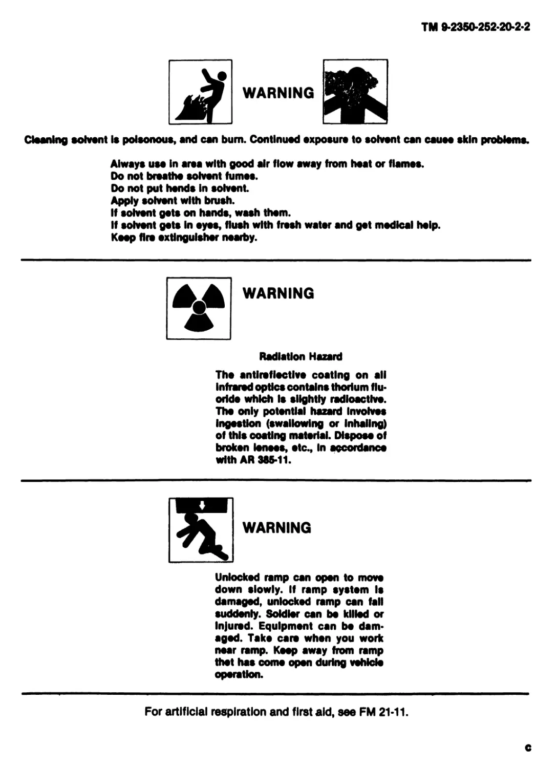
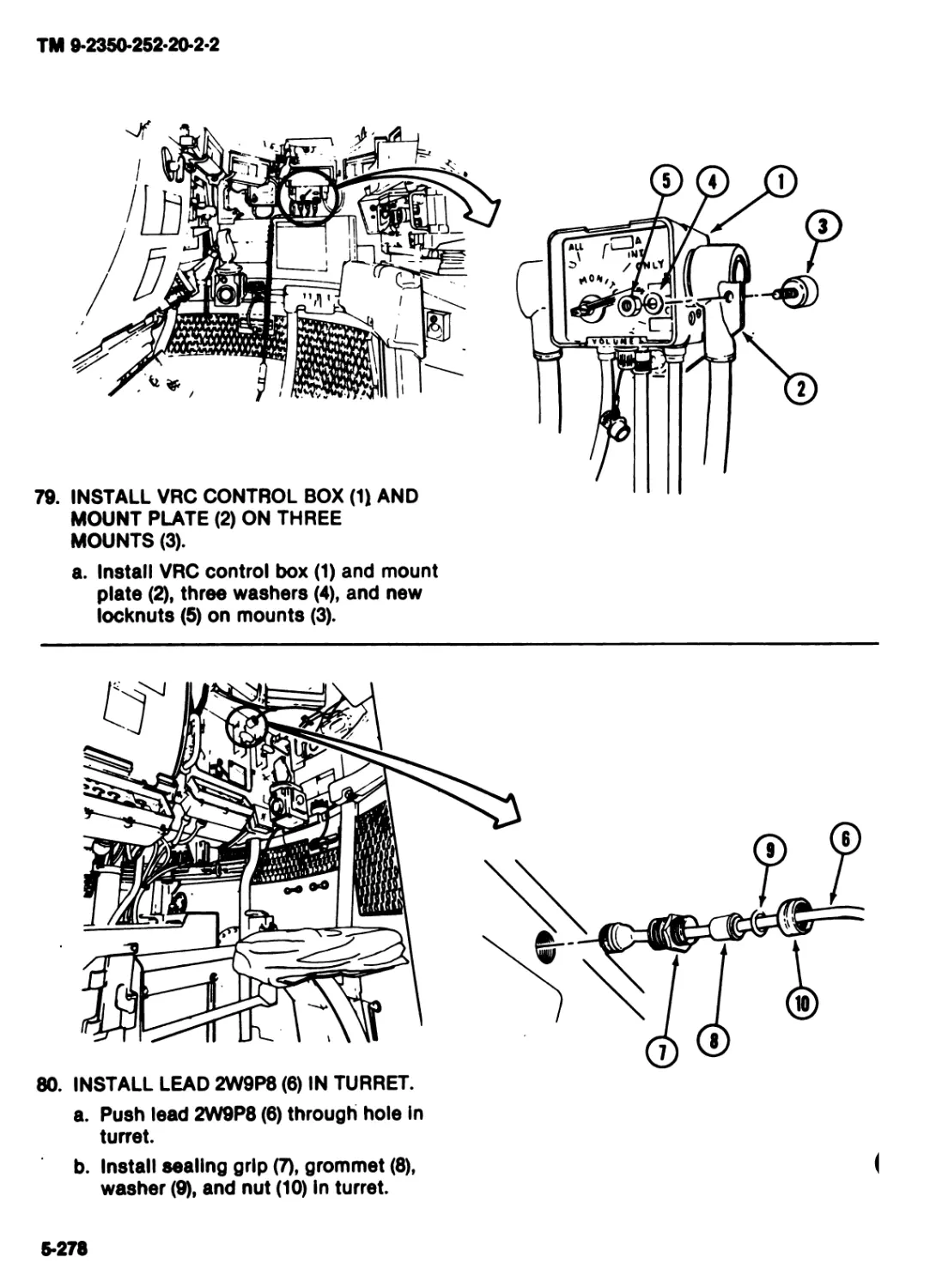
WARNING
Cleaning solvent Is poisonous, and can bum. Continued exposure to solvent can cauoe skin problems.
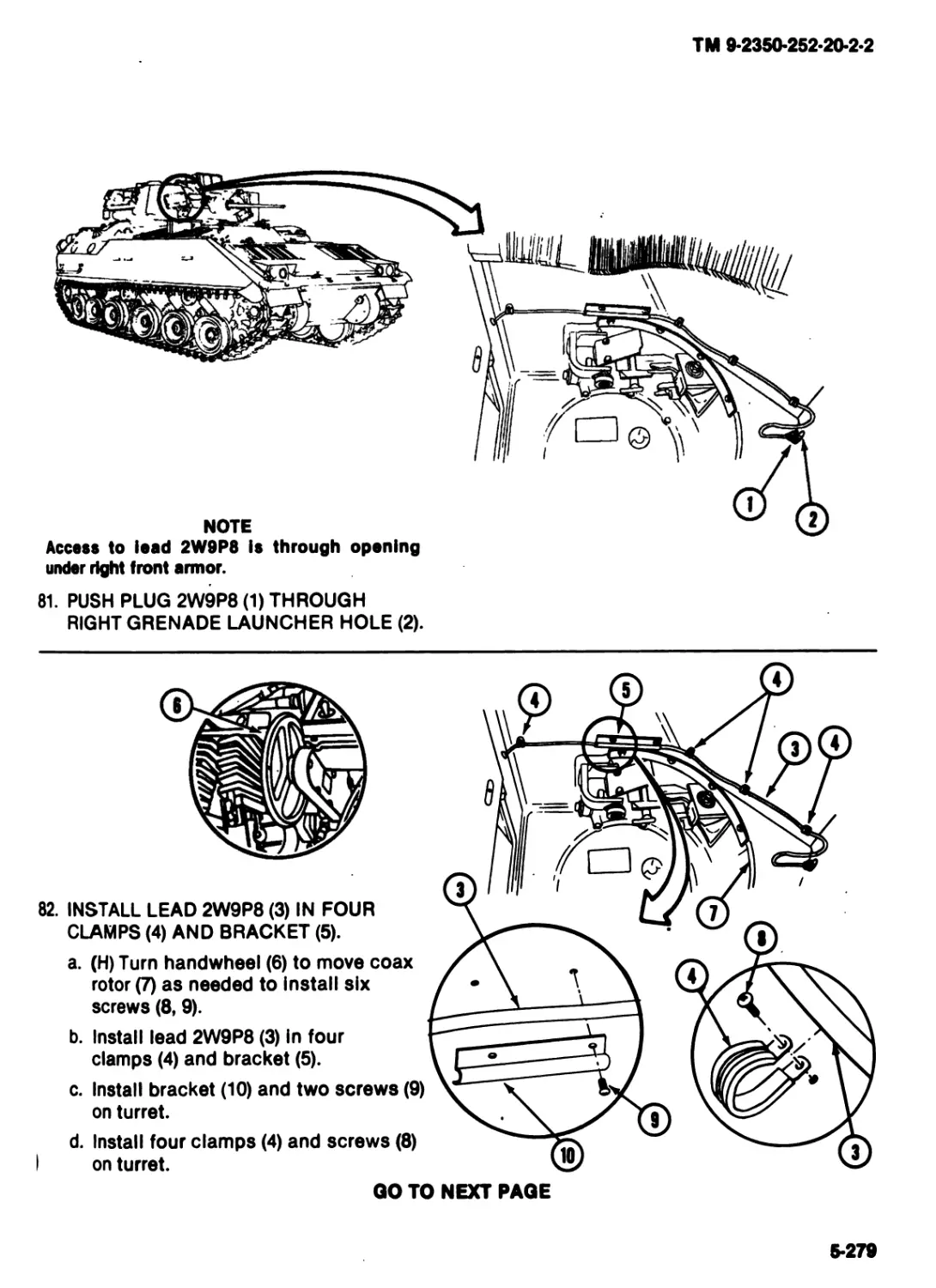
Always use in area with good air flow away from heat or flames.
Do not breathe solvent fumes.
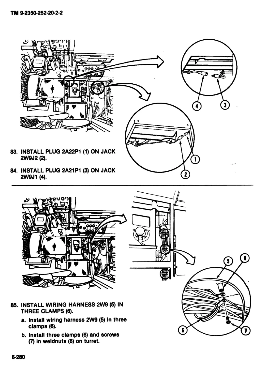
Do not put hands in solvont.
Apply solvent with brush.
If solvent gets on hands, wash thorn.
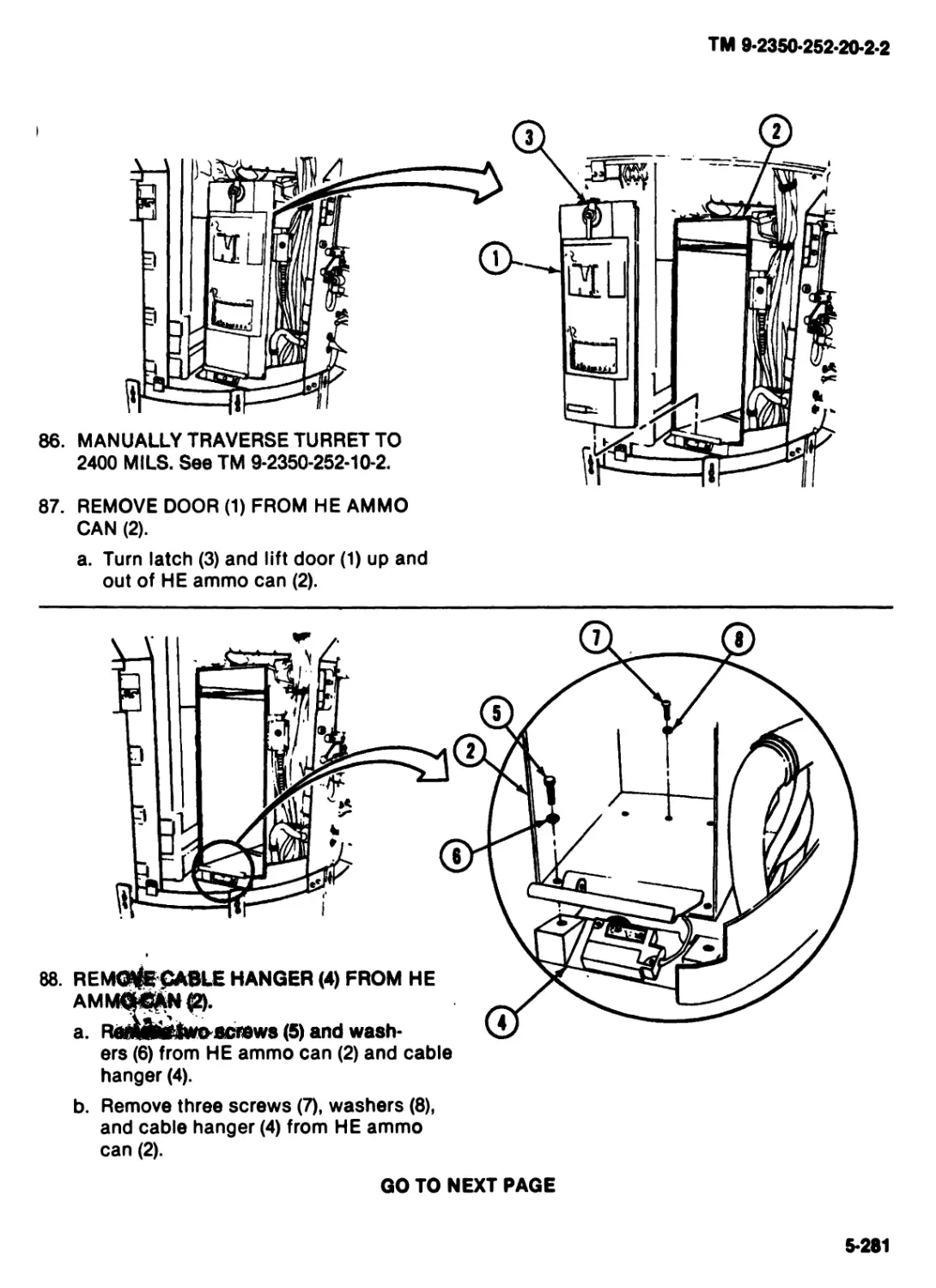
If solvent gets In eyes, flush with frosh water and get medical help.
Koop firs extinguisher nearby.
WARNING
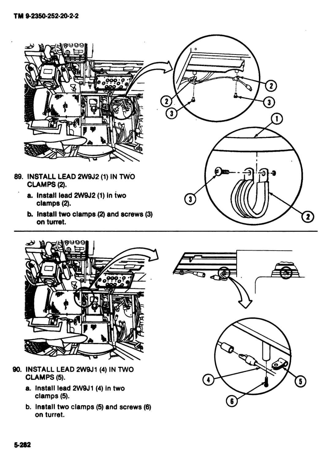
Radiation Hazard
The antlrafloctlve coating on all
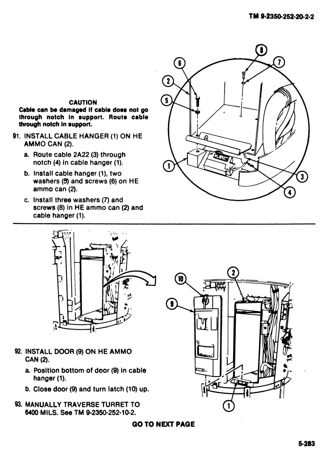
Infrared optics contains thorium flu-
oride which Is slightly radioactive.
The only potential hazard Involves
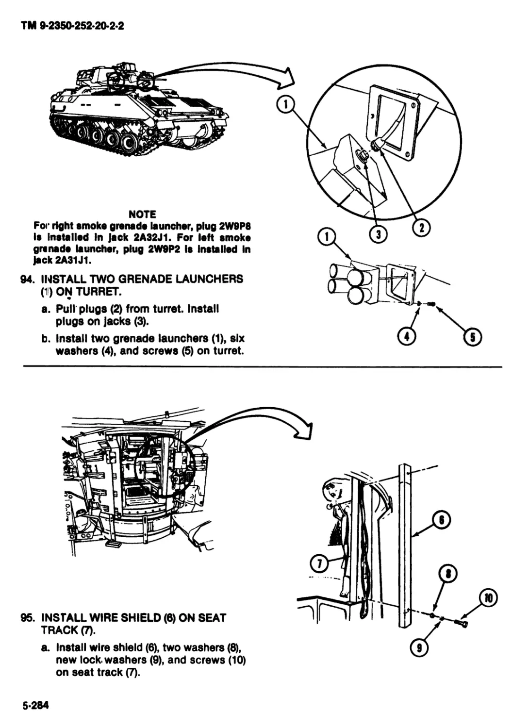
Ingestion (swallowing or Inhaling)
of this coating material. Dispose of
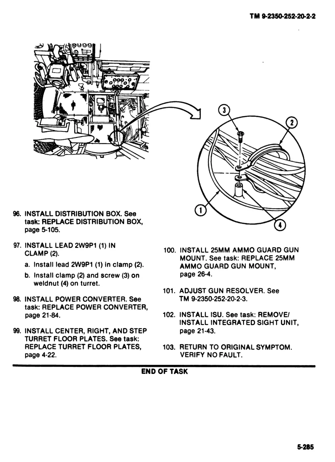
broken lonoos, etc., In accordance
with AR 355*11.
WARNING
Unlocked ramp can open to move
down slowly. If ramp system Is
damaged, unlocked ramp can fall
suddenly. Sokllor can bo killed or
Injured. Equipment can bo dam-
aged. Tako care when you work
noar ramp. Koop away from ramp
thet has сото open during vehicle
oporation.
For artificial respiration and first aid, see FM 21-11.
ТМ 9-2350-252-20-2*2
HEADQUARTERS
Technical Manual DEPARTMENT OF THE ARMY
No. 9-2350-252-20-2 WASHINGTON, DC, SEPTEMBER 1984
TECHNICAL MANUAL
ORGANIZATIONAL MAINTENANCE
FIGHTING VEHICLE, INFANTRY, М2
(2360-01-048-5920)
AND
FIGHTING VEHICLE, CAVALRY, М3
(2350-01-048-2695)
TURRET
REPORTING ERRORS AND RECOMMENDING IMPROVEMENT
You can help improve this manual. If you find any mistakes, or If
you know a way to Improve the procedures, please let us know.
. Mall your letter, DA Form 2028 (Recommended Changes to Publi-
cations and Blank Forms), or DA FORM 2028-2, located In the back
of this manual, directly to: Commander, US Army Armament Muni-
tions Command, Attn: DRSMC-MAS(R), Rock Island, IL 61299. A
reply will be furnished to you.
TABLE OF CONTENTS
Volume 2
Page
CHAPTER 4 (MAINTENANCE OF TURRET)..................................|4dl
Section I General Maintenance Tasks...........................J?..... 4-1
II Maintenance of Azimuth Indicator...........................4-17
III Maintenance of Turret Basket................................4-21
IV Maintenance of Smoke Grenade Launcher.......................4-33
V Maintenance of Communications Equipment.....................4-37
VI Maintenance of Turret Stowage ..............................4-57
VII Maintenance of Commander*s/Gunner*s Seat...................4-77
CHAPTER 5 MAINTENANCE OF TURRET ELECTRICAL SYSTEM....................5-1
Section I Maintenance of Emergency Battery Assemblies................5-1
II Maintenance of Wiring Harnesses............................5-11
III Maintenance of Electrical Systems .........................5-95
IV Maintenance of Distribution Box ...........................5-105
V Maintenance of Weapon Control Box and Display Panel........5-109
I
ТМ 9-2350-252-20-2-2
TABLE OF CONTENTS (cont)
5 MAINTENANCE OF TURRET ELECTRICAL SYSTEM (cont)
CHAPTER
Section
CHAPTER
CHAPTER
Section
CHAPTER
CHAPTER
CHAPTER
CHAPTER
CHAPTER
CHAPTER
CHAPTER
CHAPTER
VI Maintenance of 25mm Vaneaxlal Fan...........................5-115
VII Maintenance of Turret Position Indicator Box...............5-119
VIII Maintenance of Annunciator Display Panel..................5-127
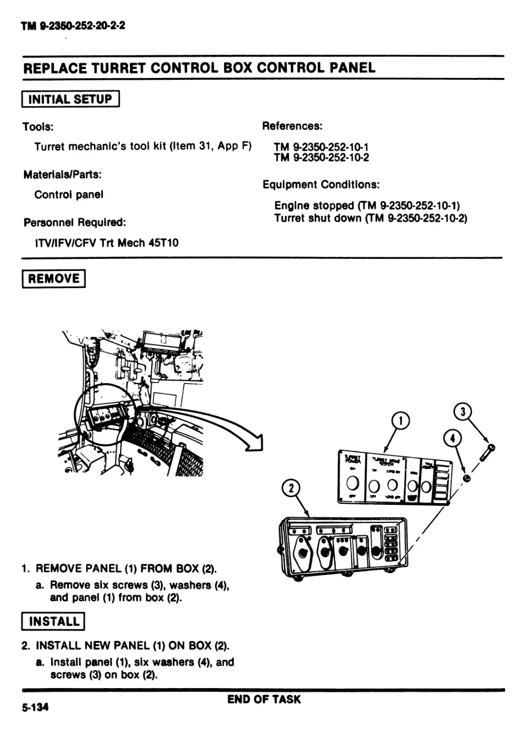
IX Maintenance of Turret Control Box...........................5-131
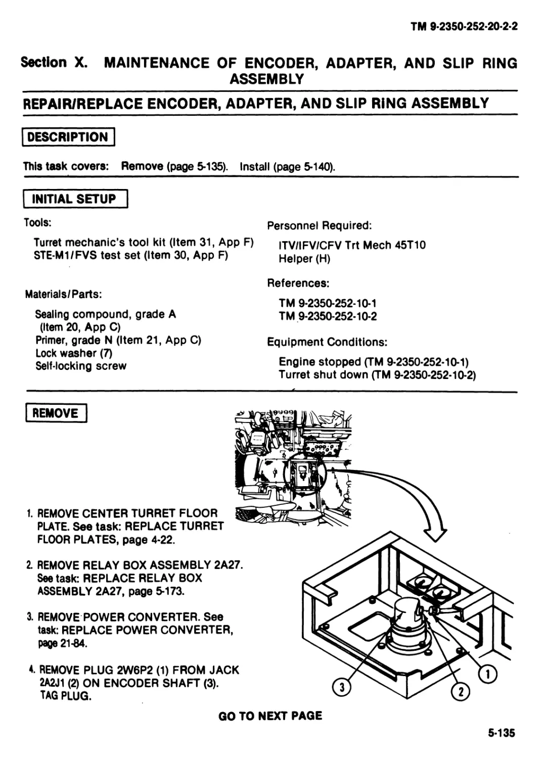
X Maintenance of Encoder, Adapter, and Slip Ring Assembly...5-135
XI Maintenance of 25mm Service Light .........................5-145
XII Maintenance of Instrument Light....... ....................5-149
XIII Maintenance of Dome Light ................................5-155
XIV Maintenance of Emergency Batteries.........................5-167
XV Maintenance of Relay Box Assembly..........................5-173
XVI Maintenance of Cable Assemblies............................5-177
6 MAINTENANCE OF HATCHES....................................6-1
7 MAINTENANCE OF TURRET DRIVll................... ...........ED
I Maintenance of Turret Drive ..............................7-1
II Maintenance of Gun Elevation Drive, Motor, and Gearbox....7-7
III Maintenance of Traverse Drive, Motor, and Gearbox • ......7-61
IV Maintenance of Commander’s Handstation ..».................7-117
V Maintenance of Gunner’s Handstation.......................7-123
VI Maintenance of Electronic Control Assembly.................7-127
VII Maintenance of Gun and Pitch Gyros........................7-135
8 MAINTENANCE OF CUSHIONS.......................8-1
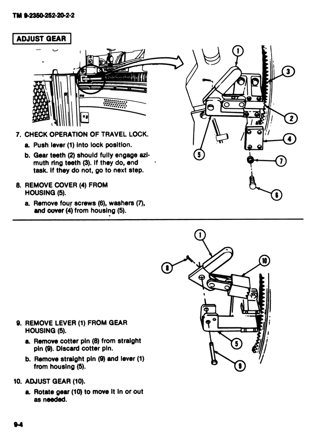
9 MAINTENANCE OF TRAVEL LOCK....................9-1
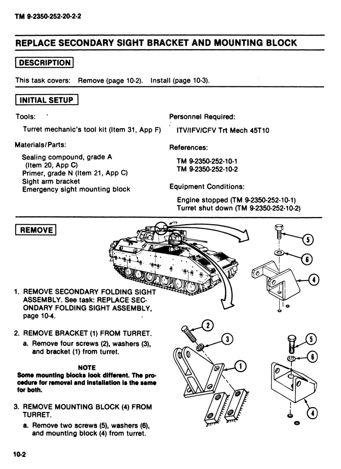
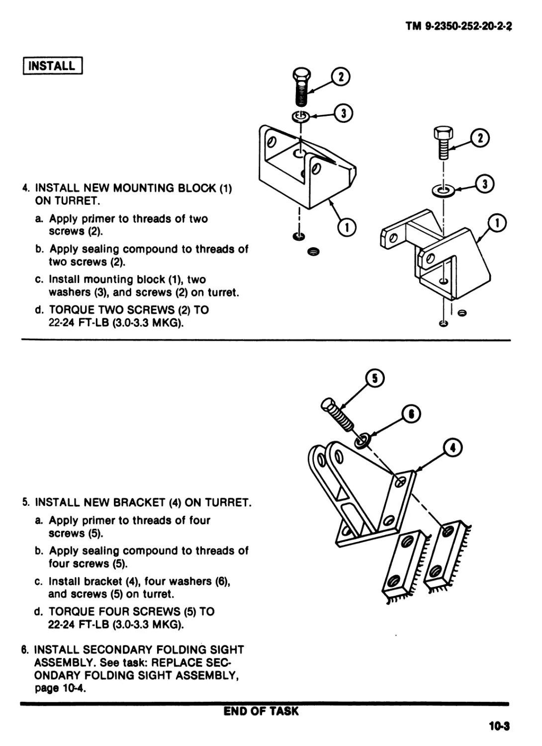
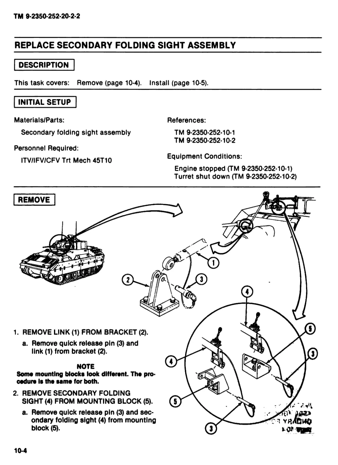
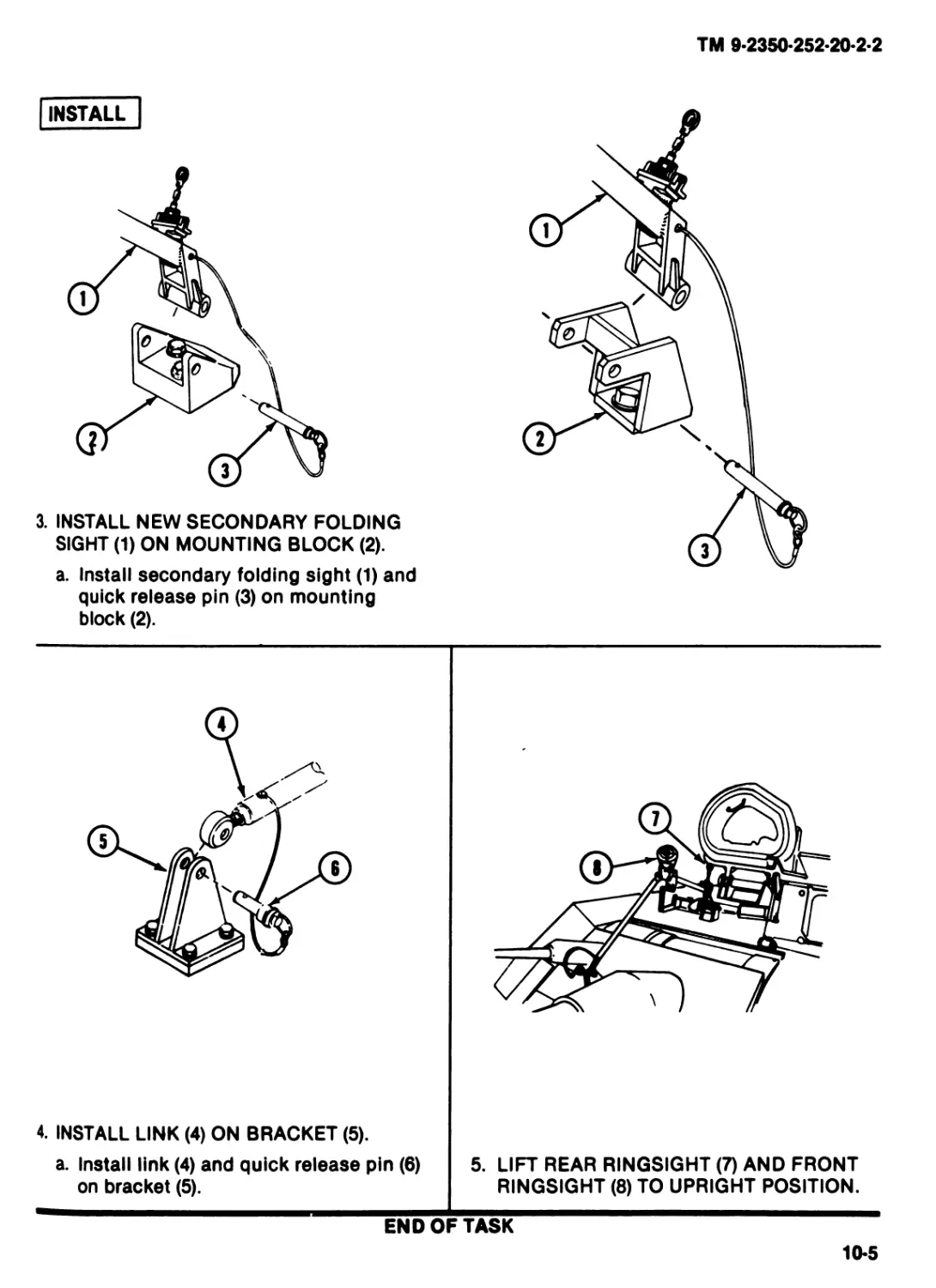
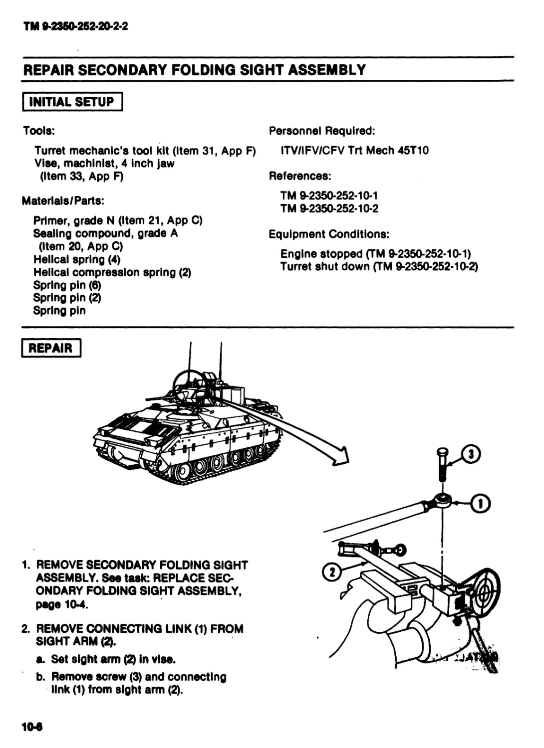
10 MAINTENANCE OF SECONDARY SIGHT...............10-1
11 MAINTENANCE OF BOLT-ON ARMOR ................11-1
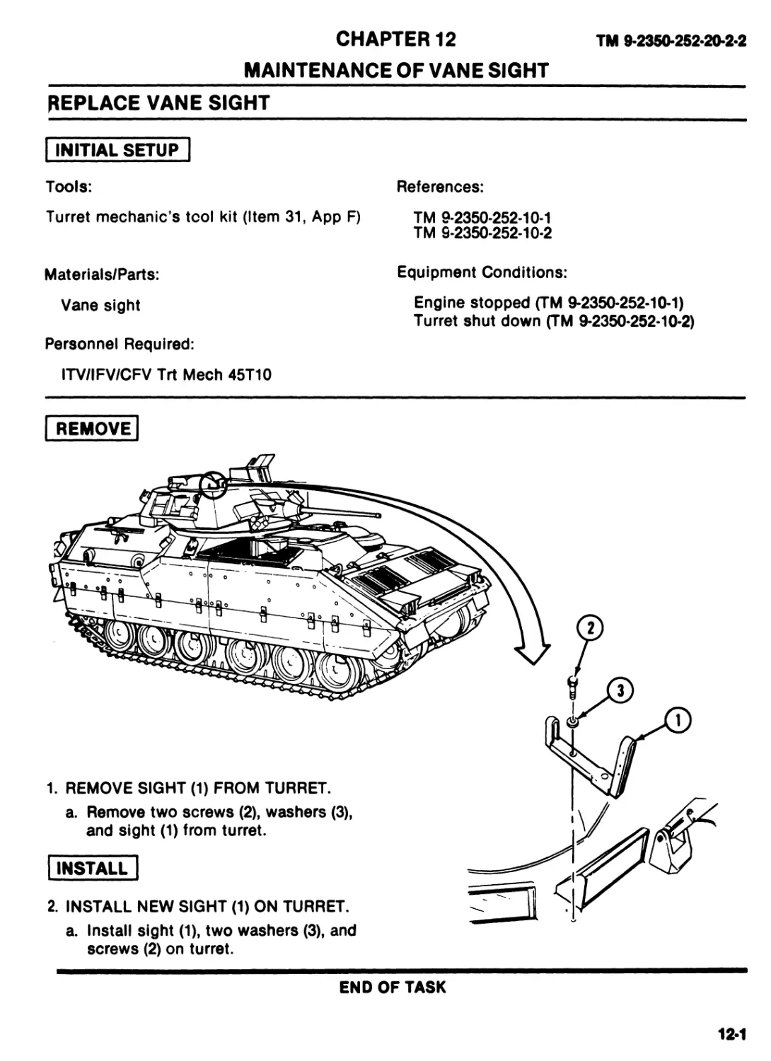
12 MAINTENANCE OF VANE SIGHT ...................12-1
13 MAINTENANCE OF COAX MACHINE GUN
BULKHEAD DOORS....................................13-1
14 MAINTENANCE OF 25MM GUN GUARD................14-1
15 MAINTENANCE OF POINTER INDICATOR ............15-1
H
ТМ 9-2350-252-20-2-2
TABLE OF CONTENTS (cant)
Page
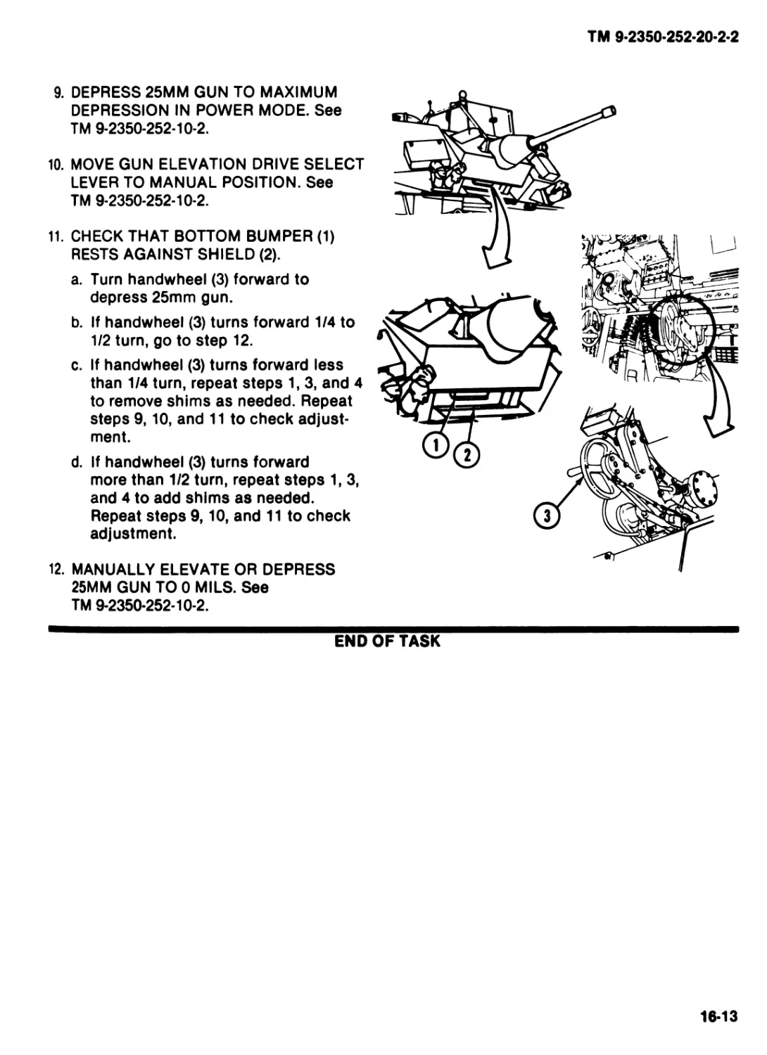
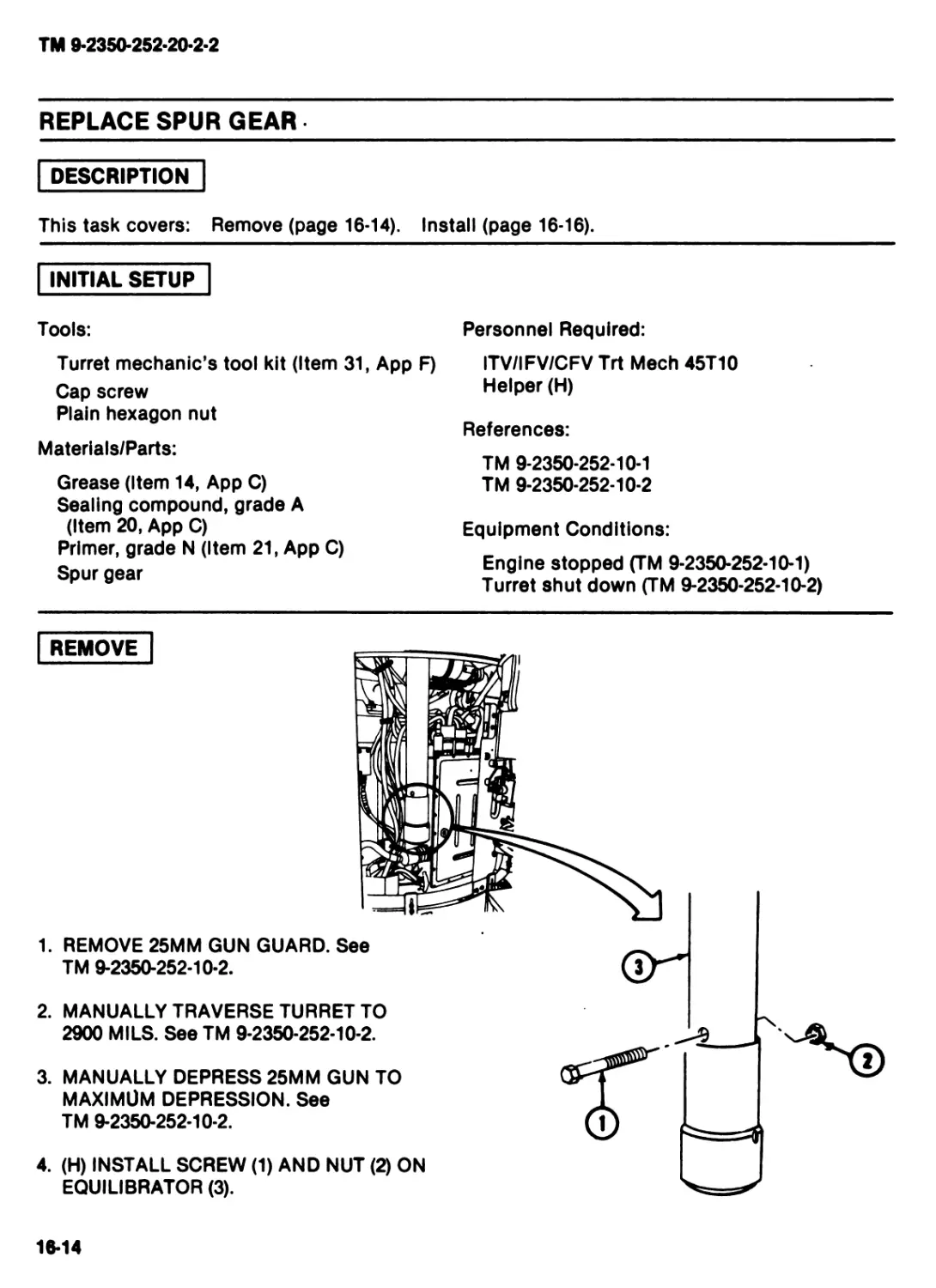
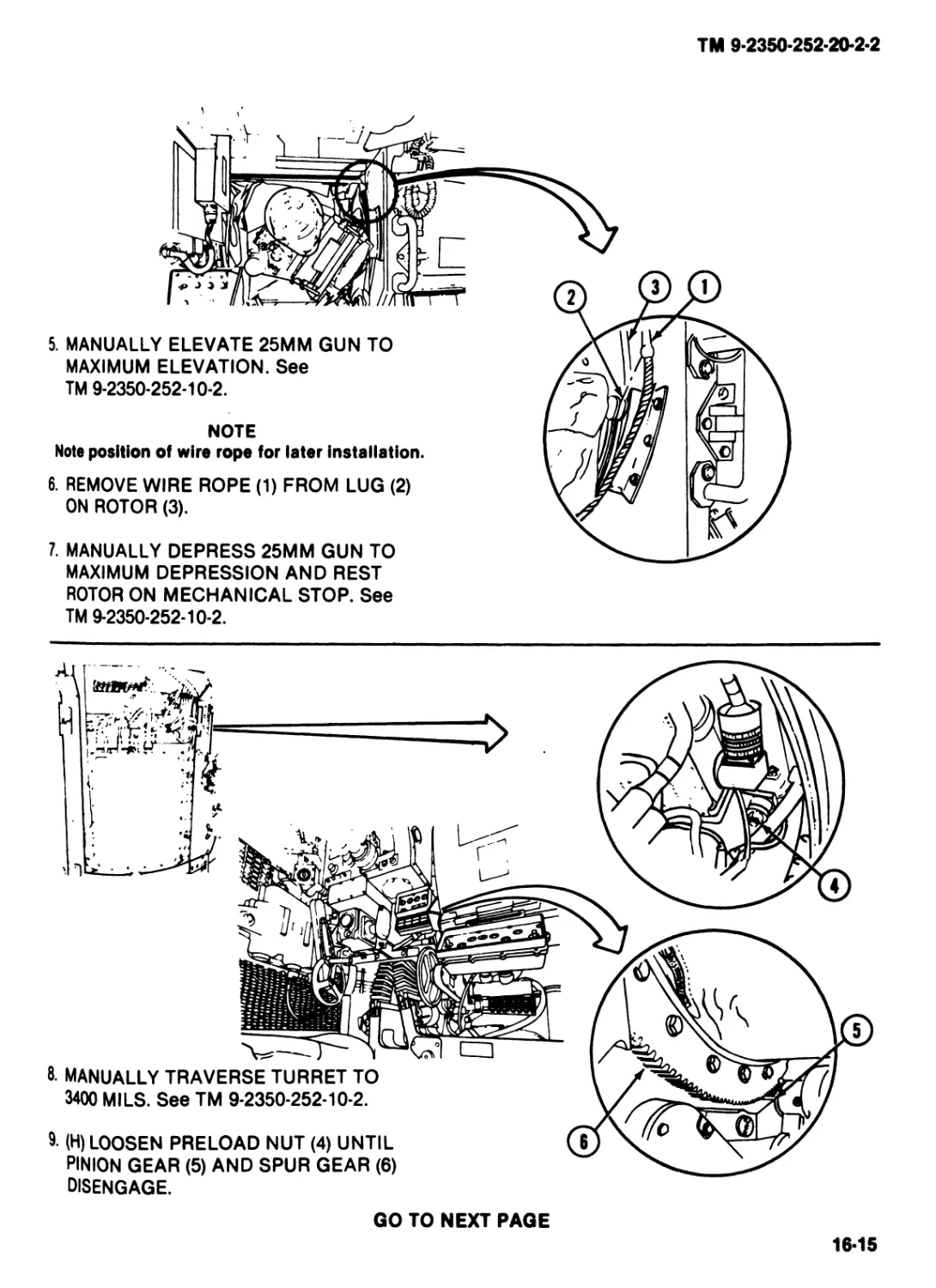
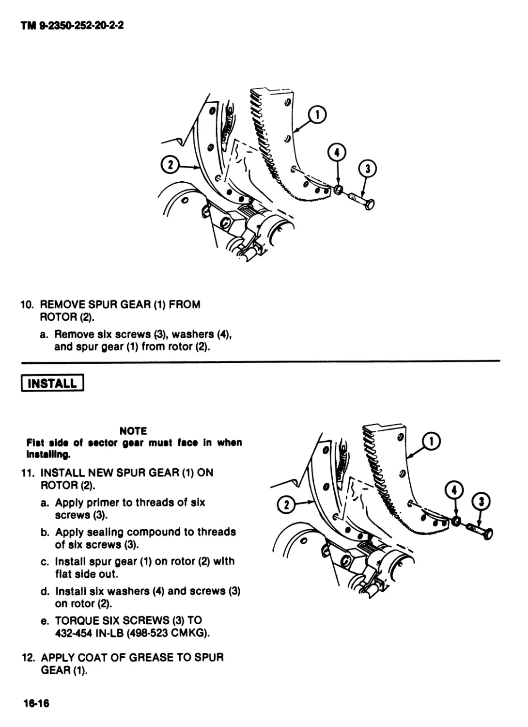
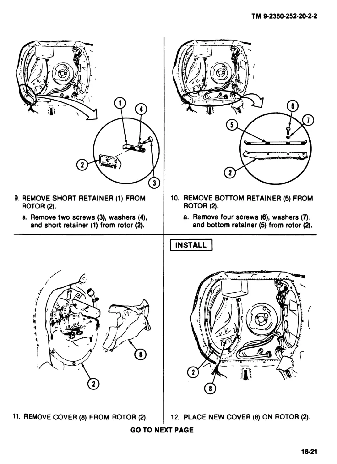
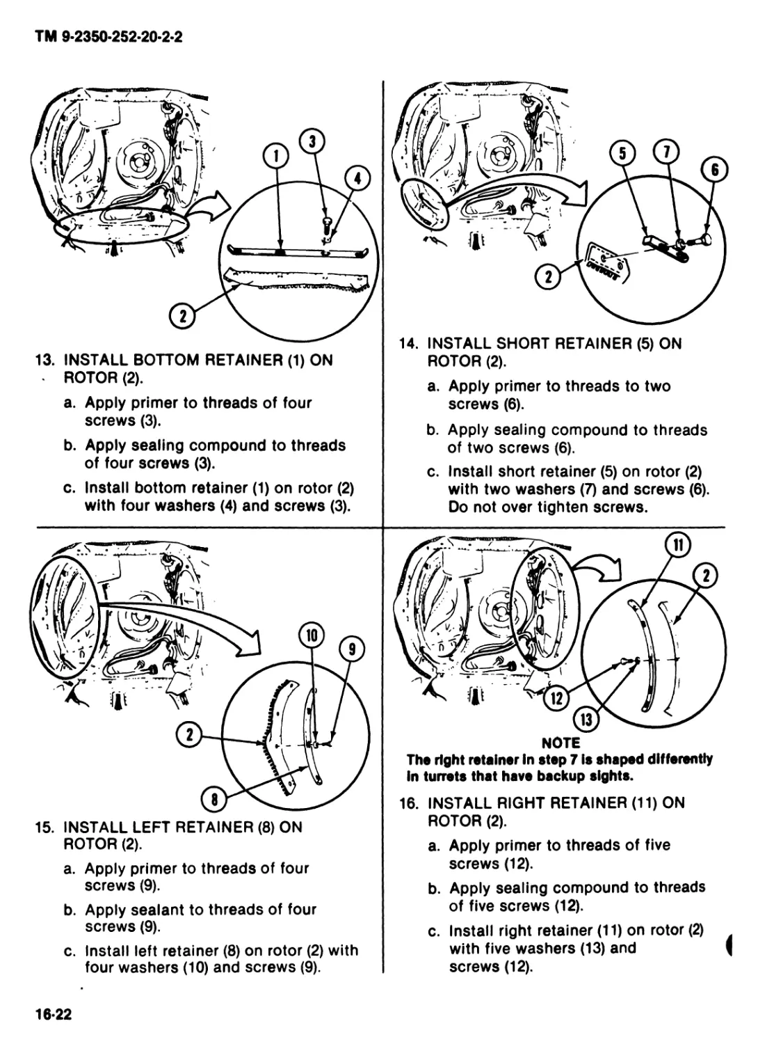
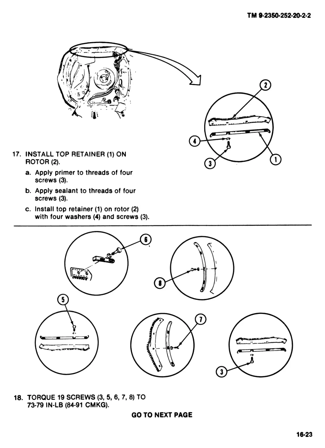
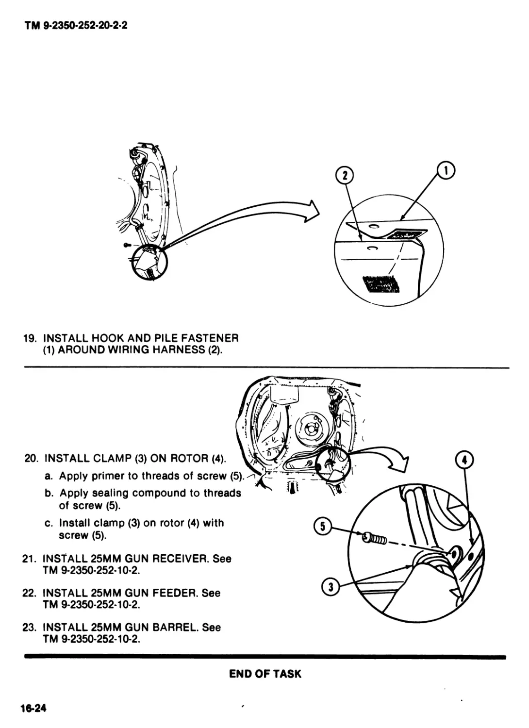
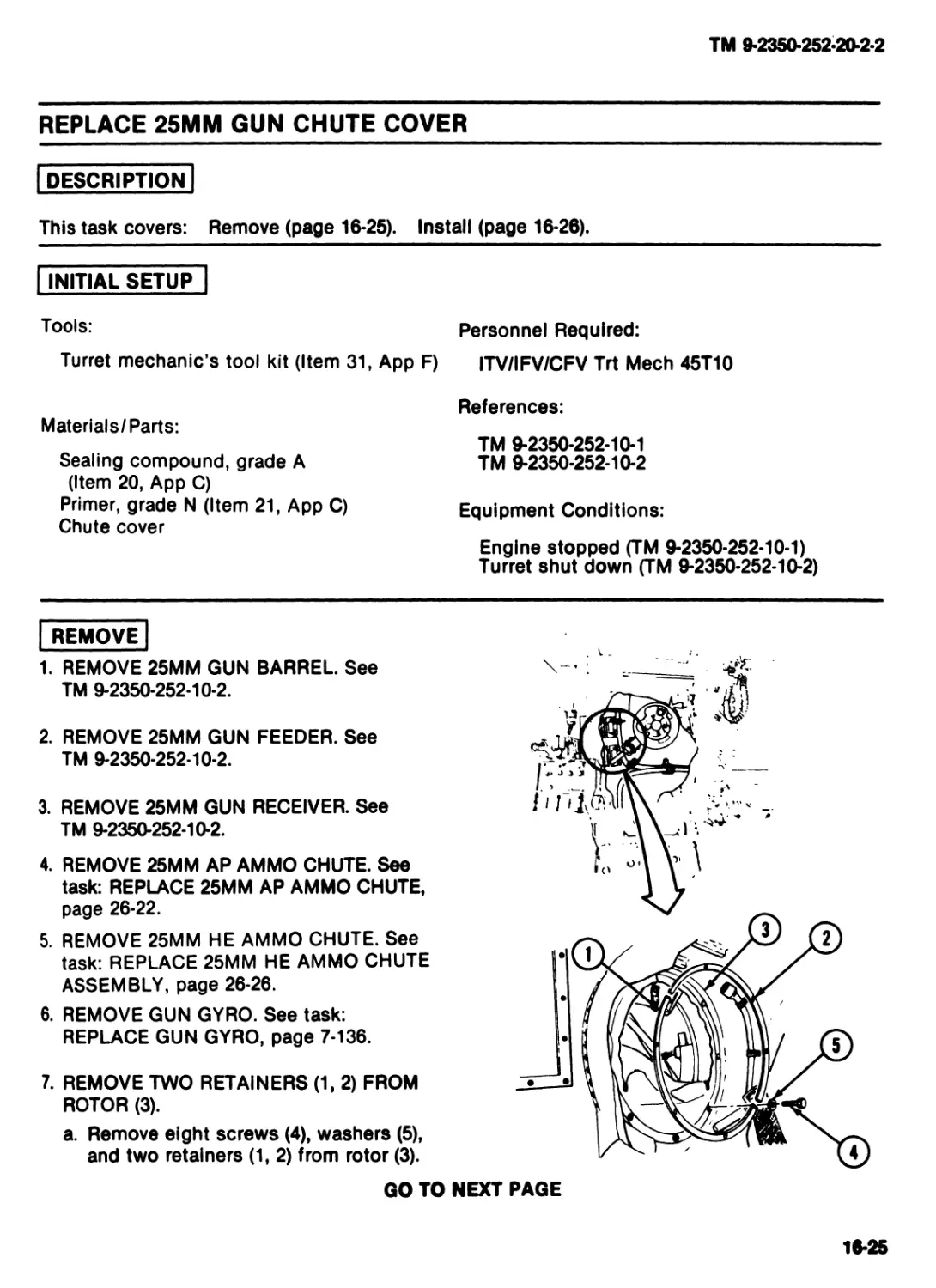
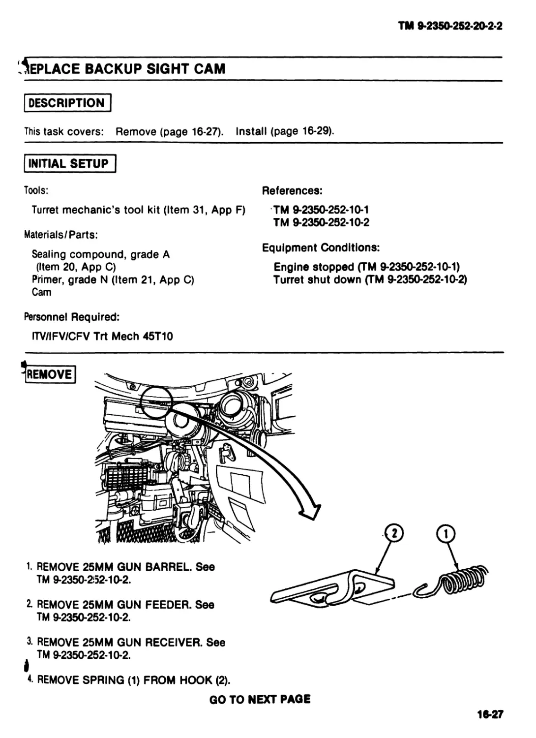
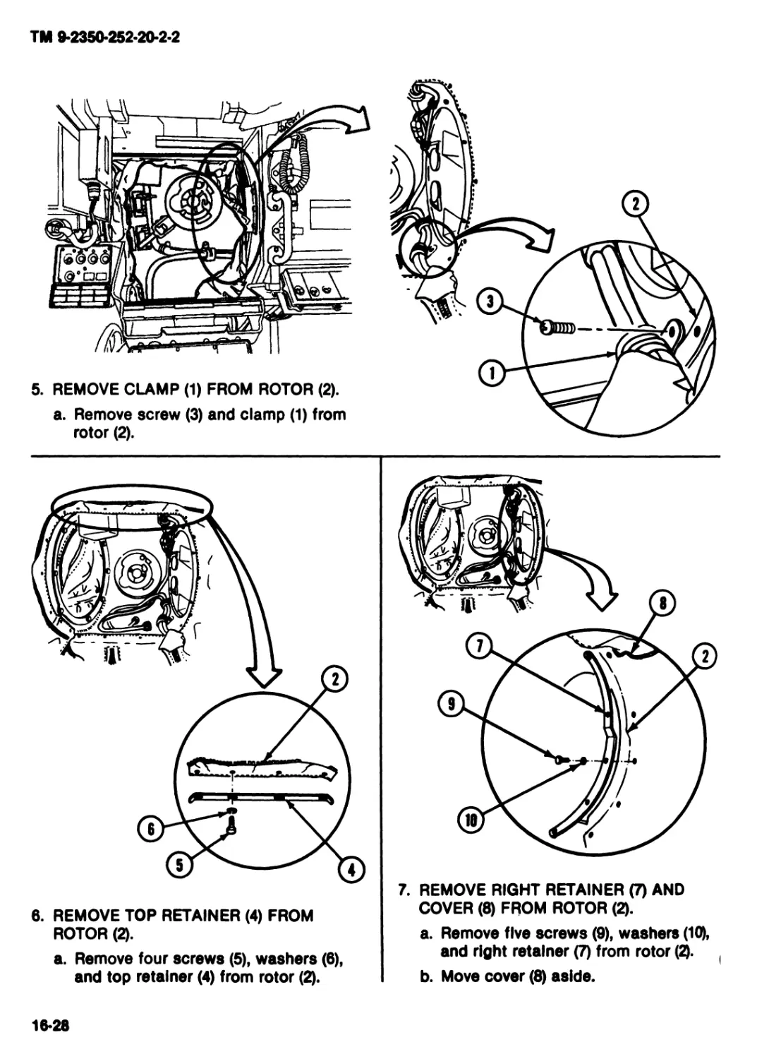
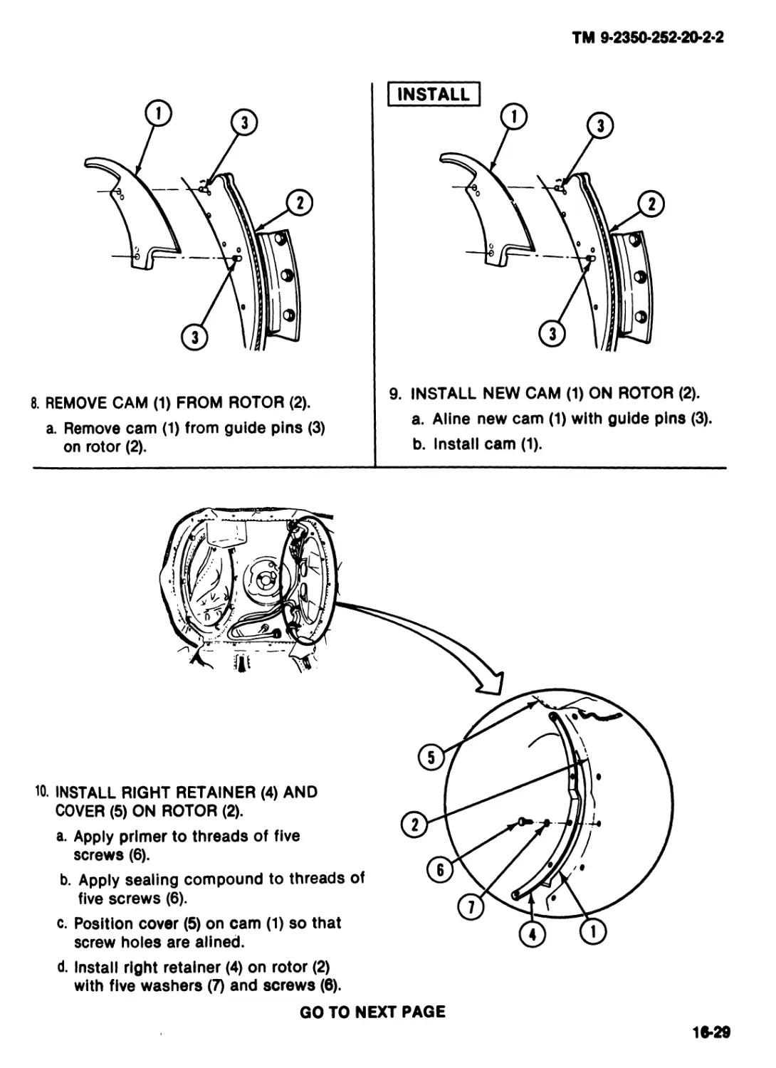
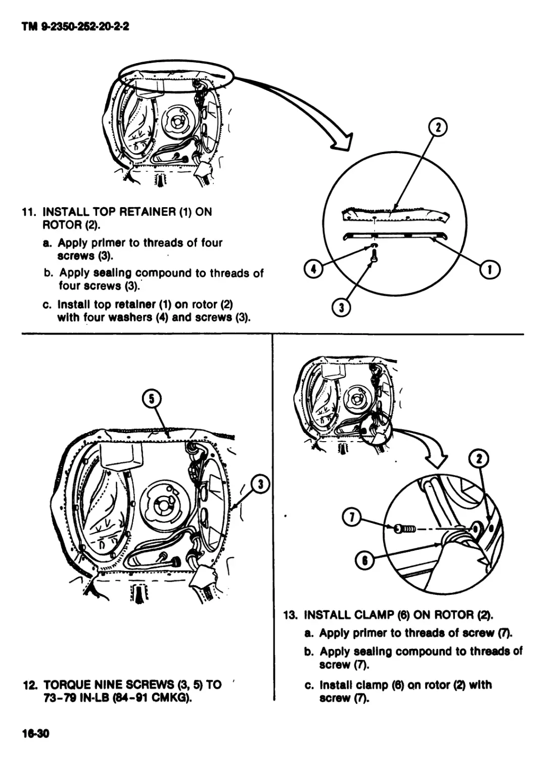
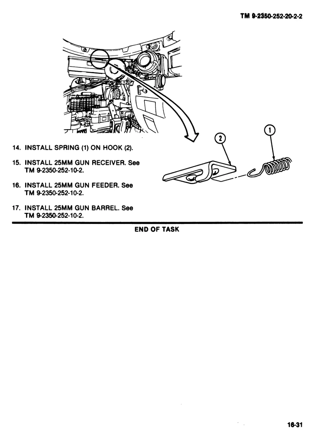
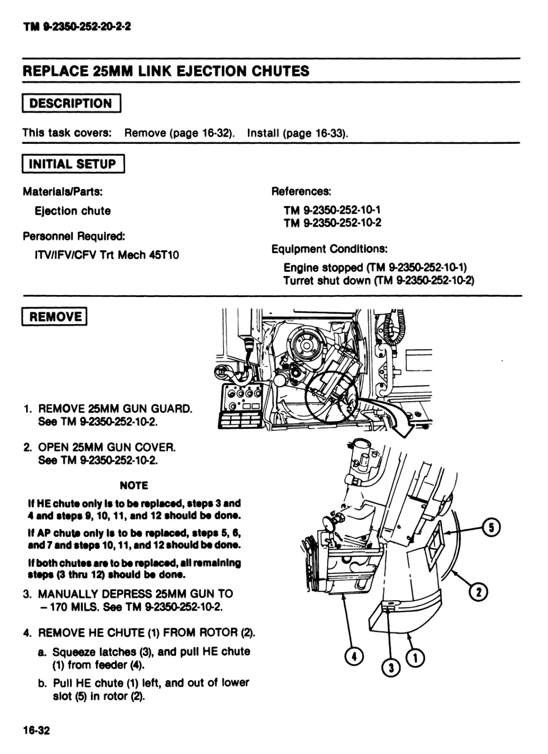
CHAPTER 16 [MAINTENANCE OF 25MM GUN AND ROTOR].........................Red]
Section I Maintenance of 25mm Gun and Rotor................................16-1
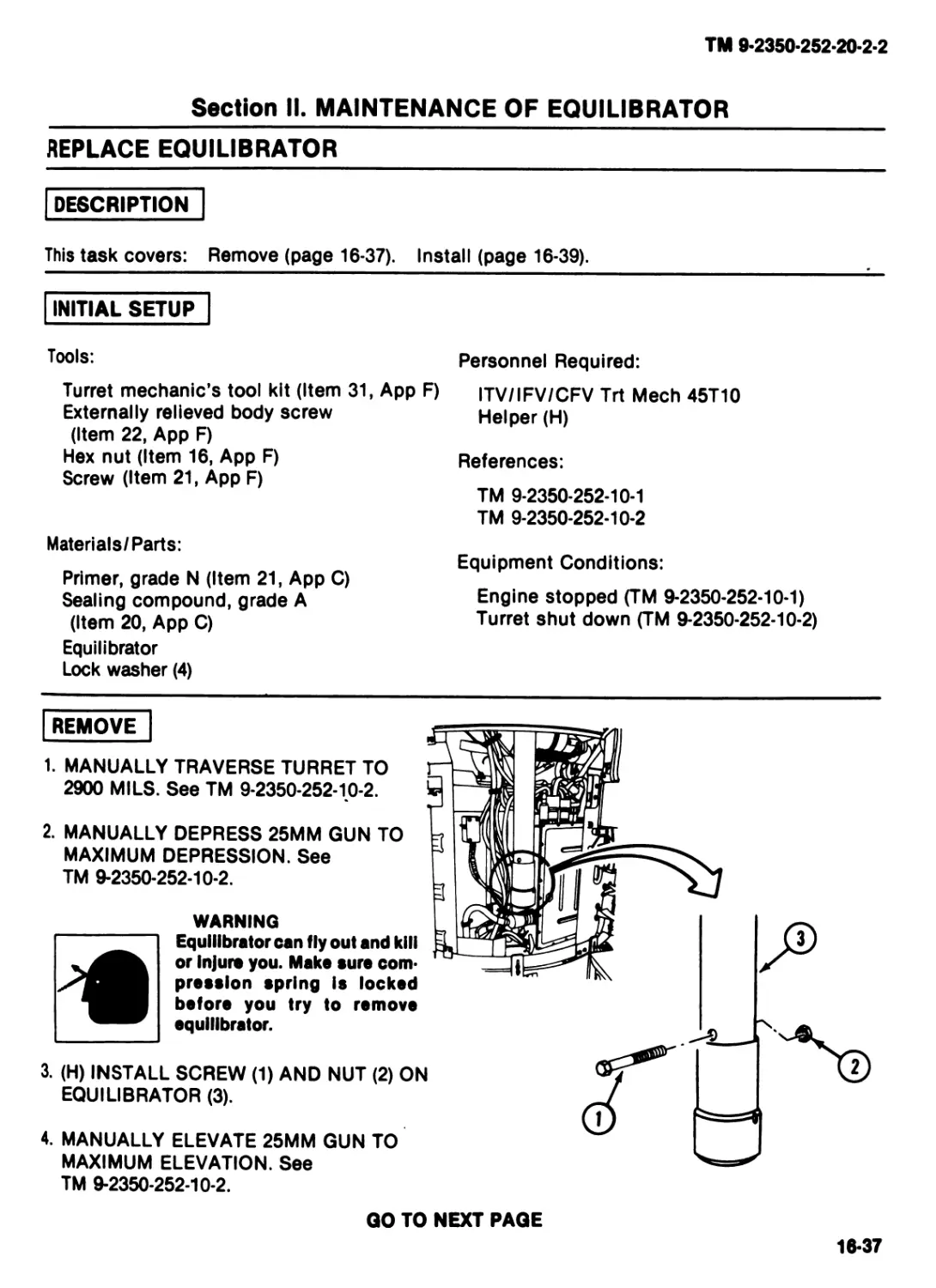
II Maintenance of Equilibrator............................ 16-37
III Maintenance of 25mm Gun Mount ............................16-41
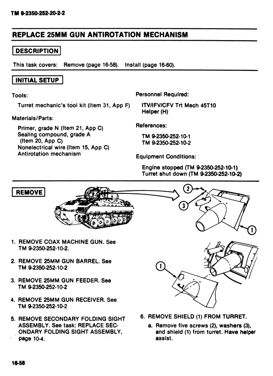
IV Maintenance of 25mm Gun Antirotation Mechanism............16-57
CHAPTER 17 MAINTENANCE OF TURRET SLOPE
INDICATOR....................................................................17-1
ALPHABETICAL INDEX — VOLUME 2
DA FORM 2028-2.............................................Rear of Volume
METRIC CONVERSION CHART..................Inside Rear Cover
ТМ 9-2350-252 20 2-2
CHAPTER 4
MAINTENANCE OF TURRET
Section I. GENERAL MAINTENANCE TASKS
TASK INDEX
Task
Page
Task
Page
Replace Markers or Decals
4-2
Repair Single Pin Plug or Jack
4-7
Repair Lead
4-4
Repair Multipin Plug/Jack, Rubber Type . 4-12
4-1
ТМ 9-2350-252-20-2-2
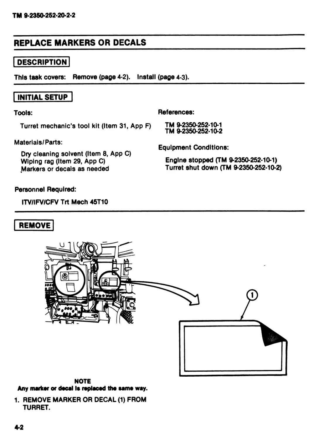
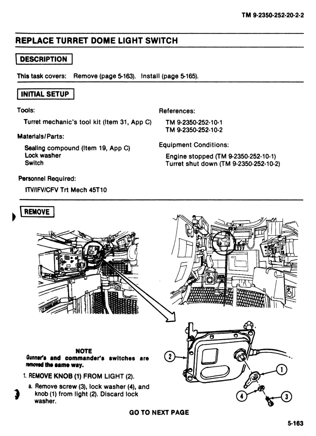
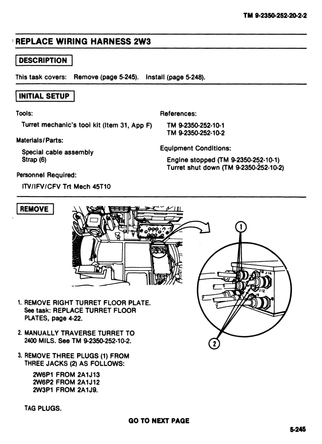
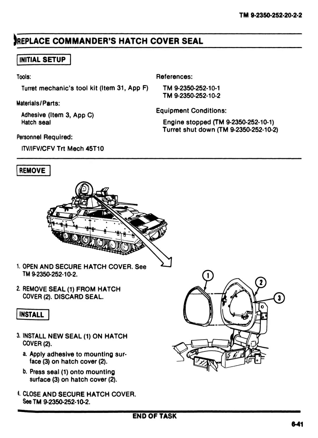
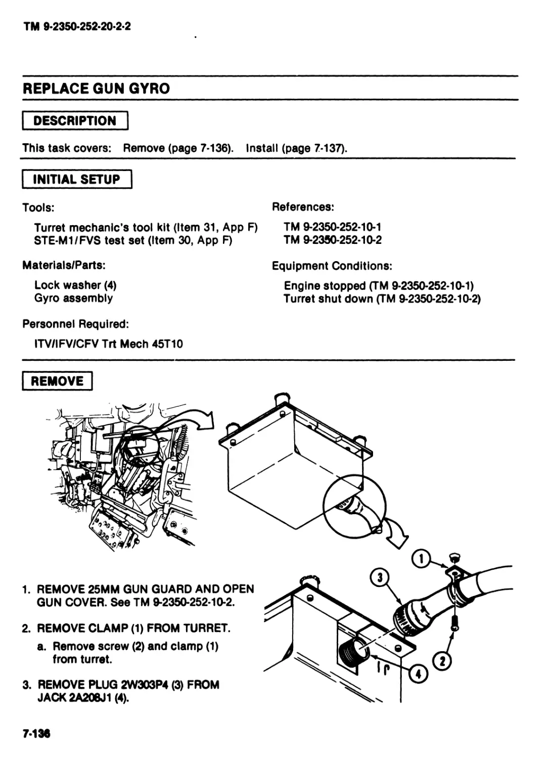
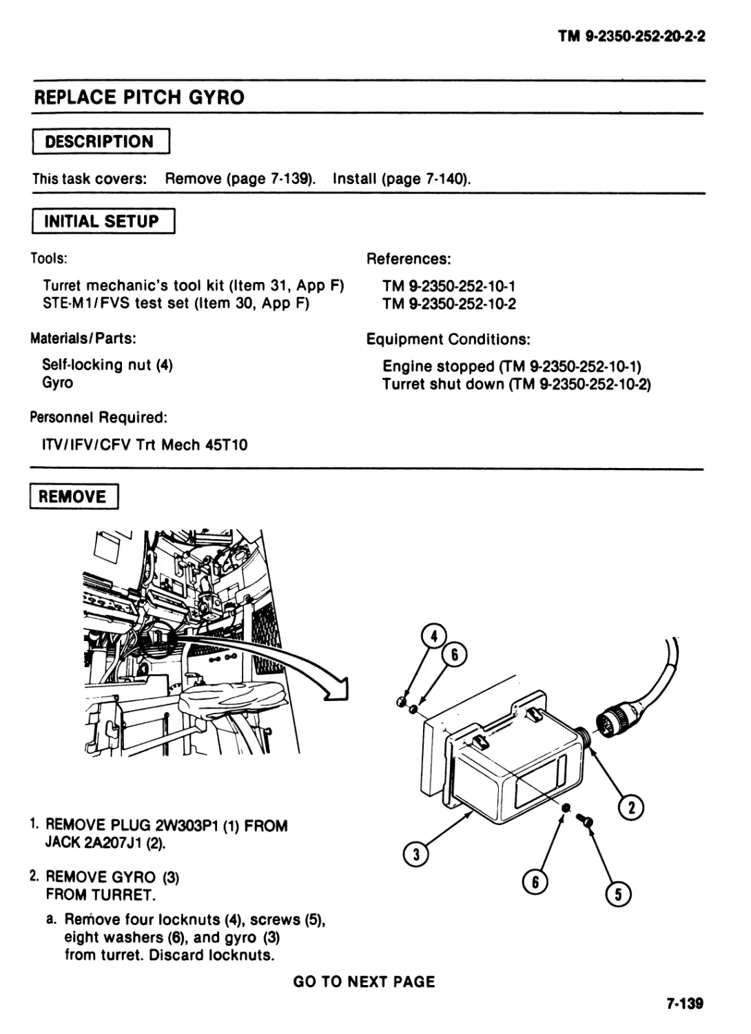
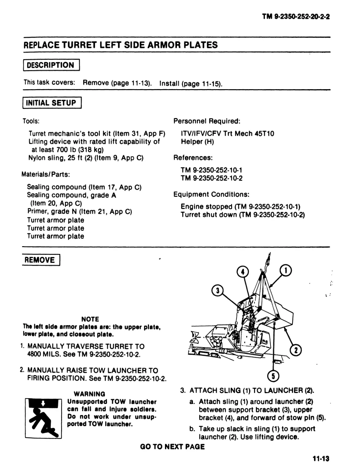
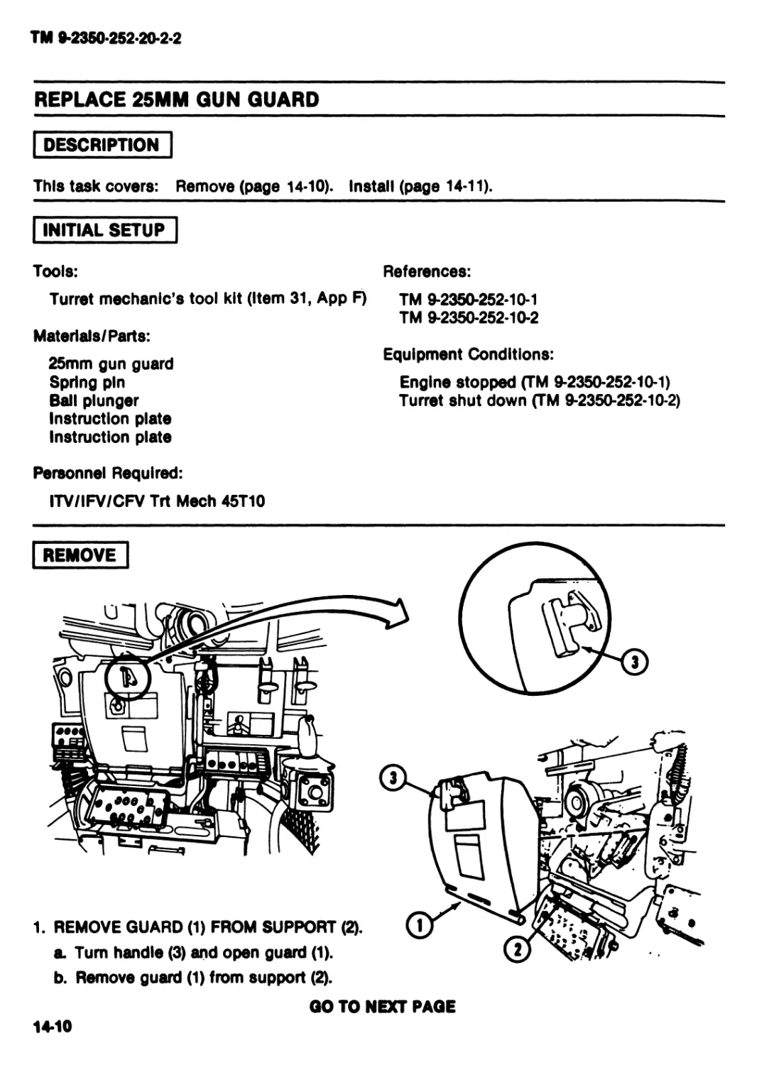
REPLACE MARKERS OR DECALS
DESCRIPTION
This task covers: Remove (page 4-2). Install (page 4-3).
I INITIAL SETUP
Tools:
References:
Turret mechanic’s tool kit (Item 31, App F) TM 9-2350-252-10-1
TM 9-2350-252-10-2
Materials/Parts:
Dry cleaning solvent (Item 8, Арр C)
Wiping rag (Item 29, Арр C)
.Markers or decals as needed
Equipment Conditions:
Engine stopped (TM 9-2350-252-10-1)
Turret shut down (TM 9-2350-252-10-2)
Personnel Required:
ITV/IFV/CFV Trt Meeh 45T10
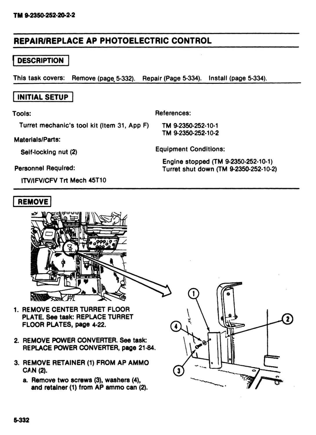
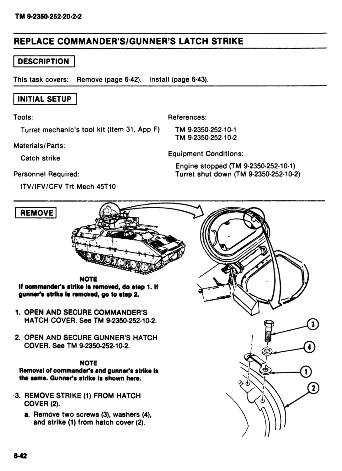
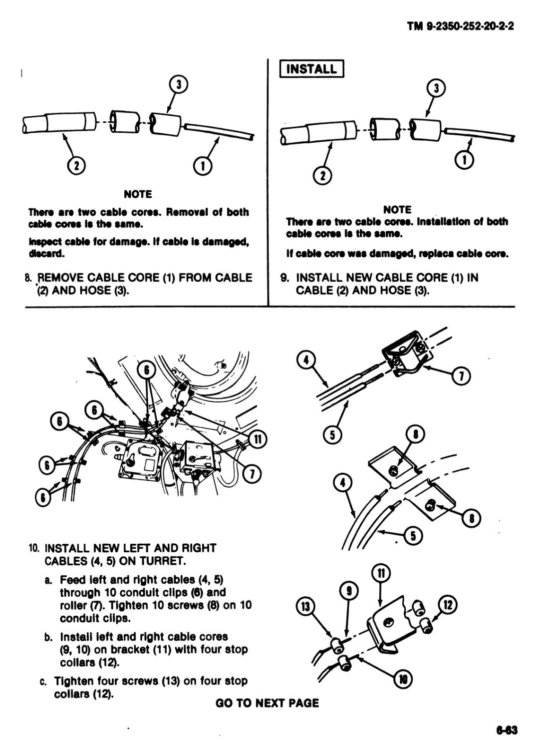
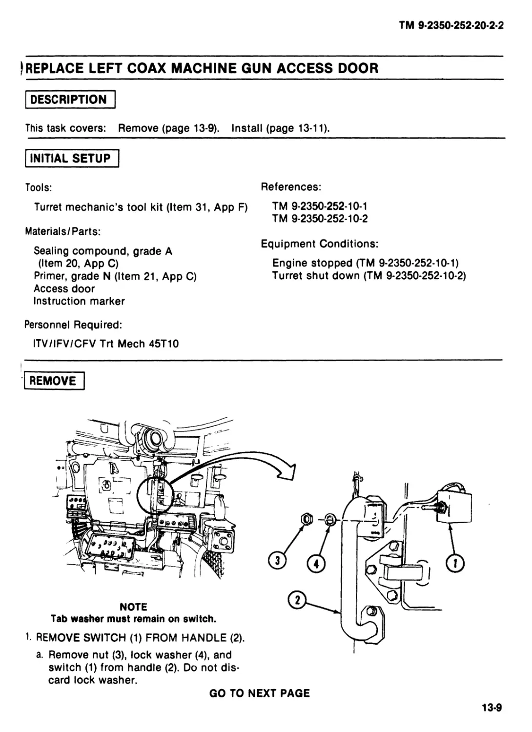
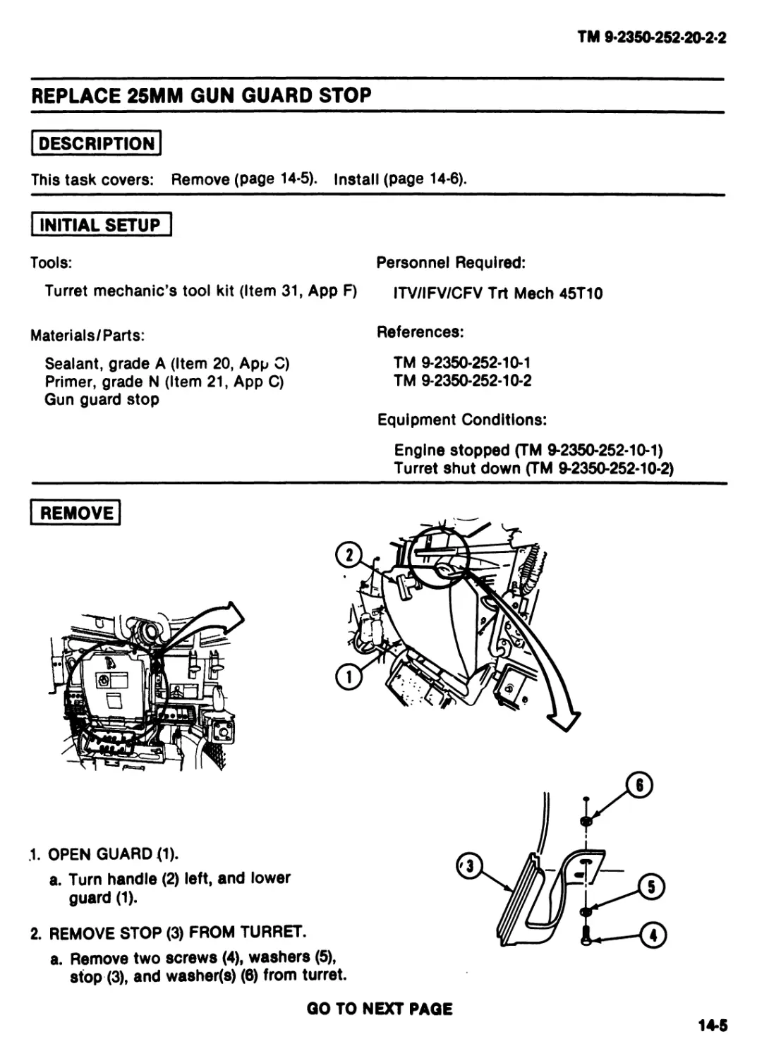
REMOVE
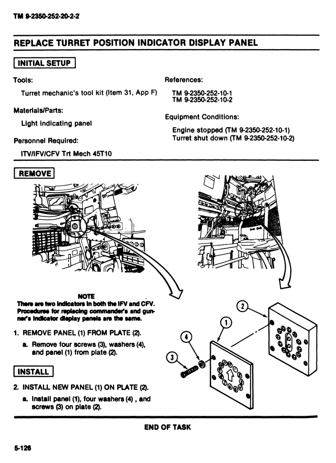
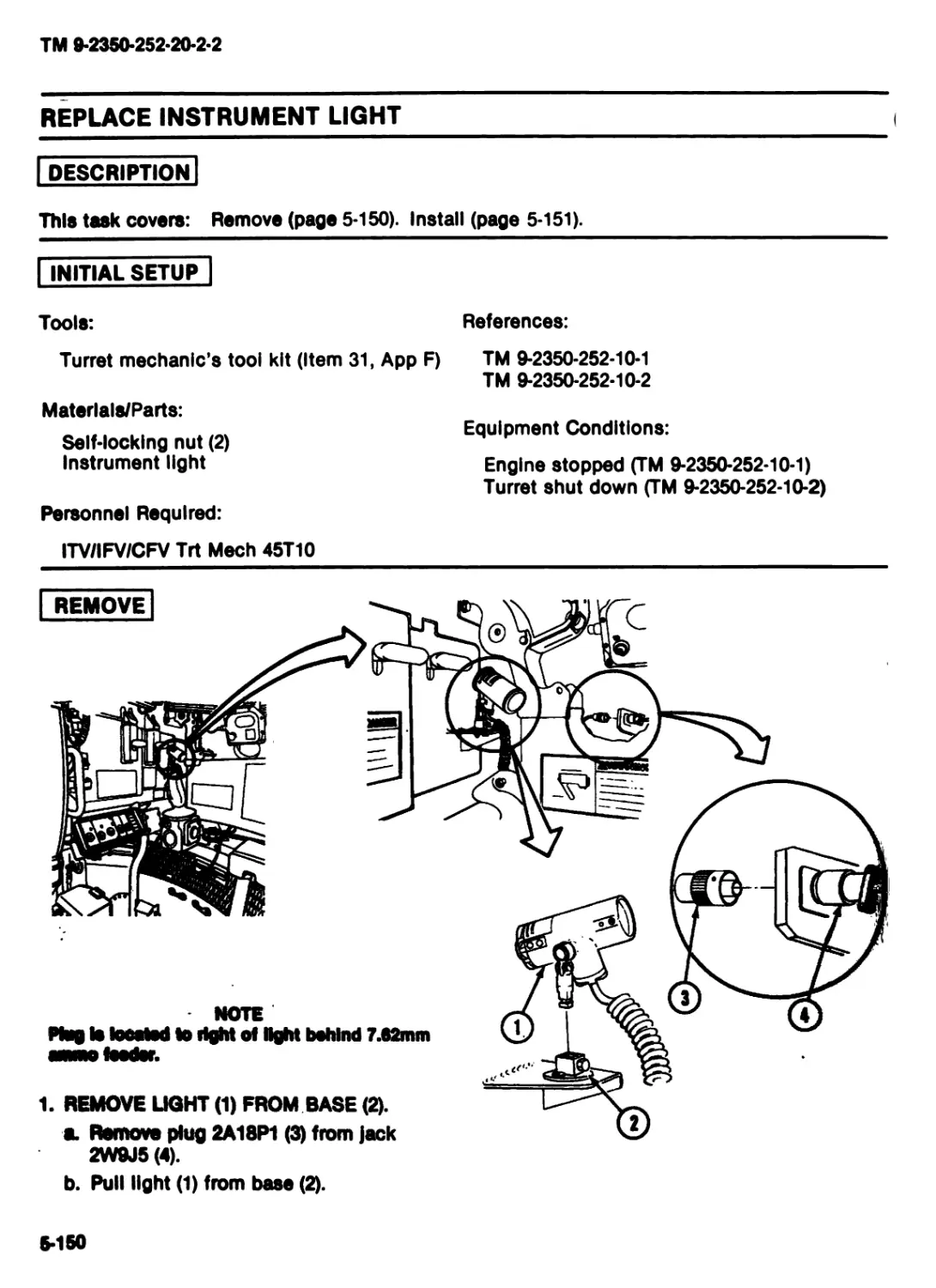
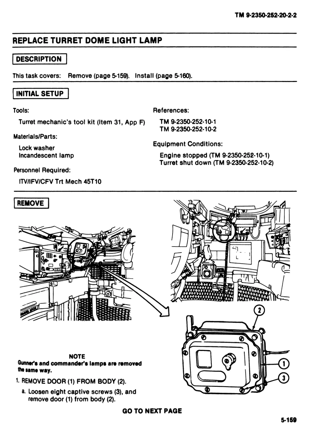
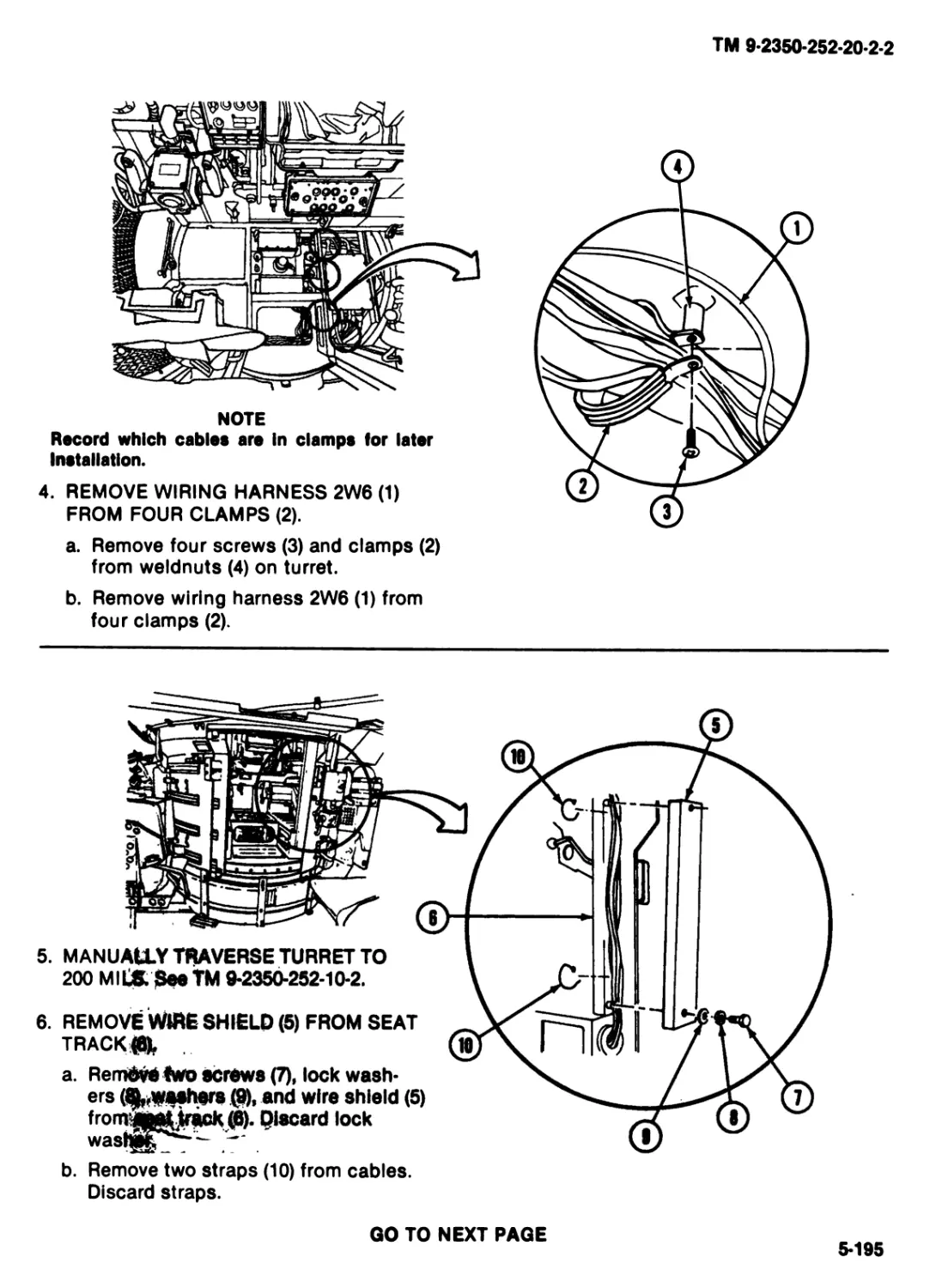
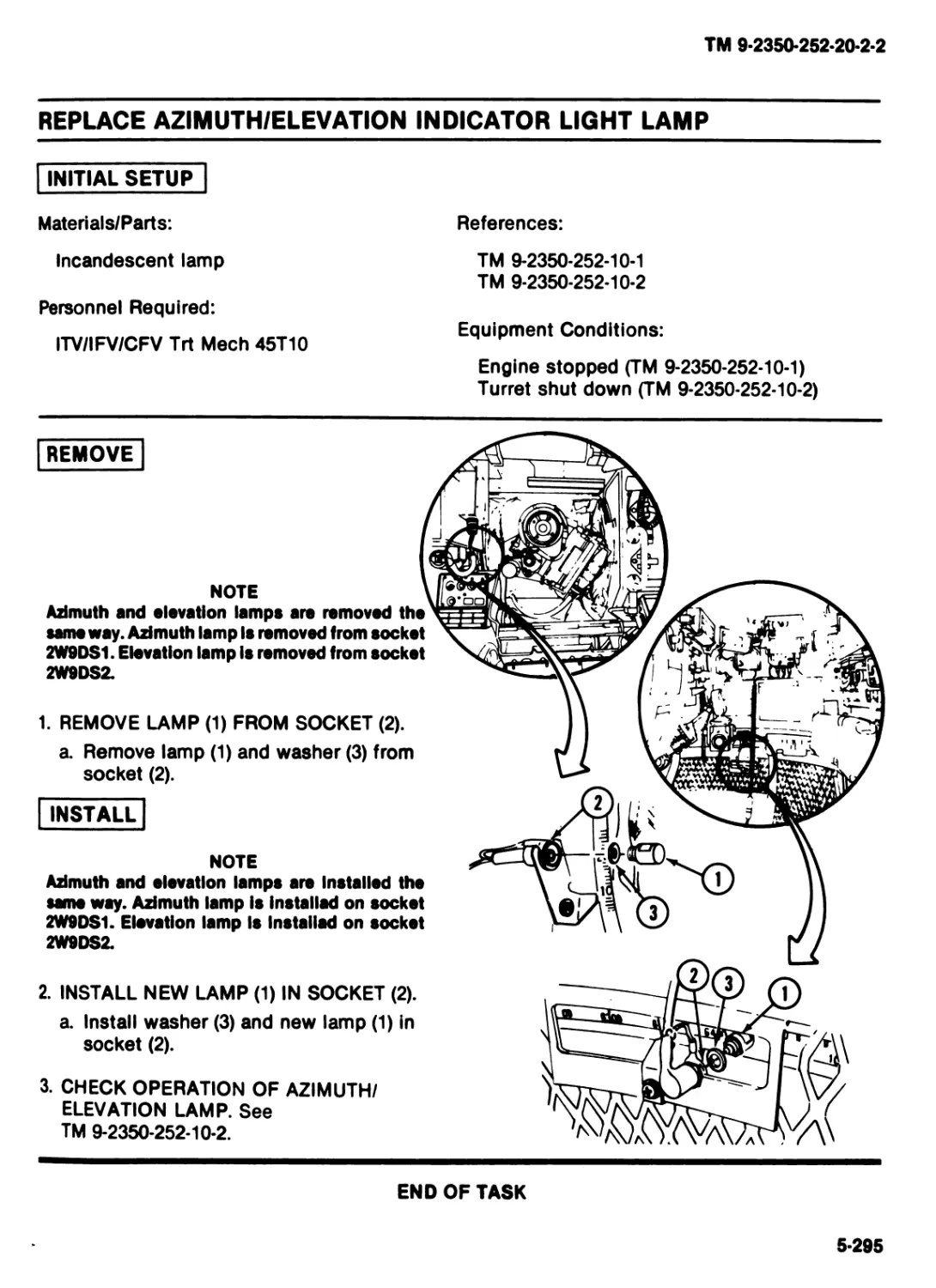
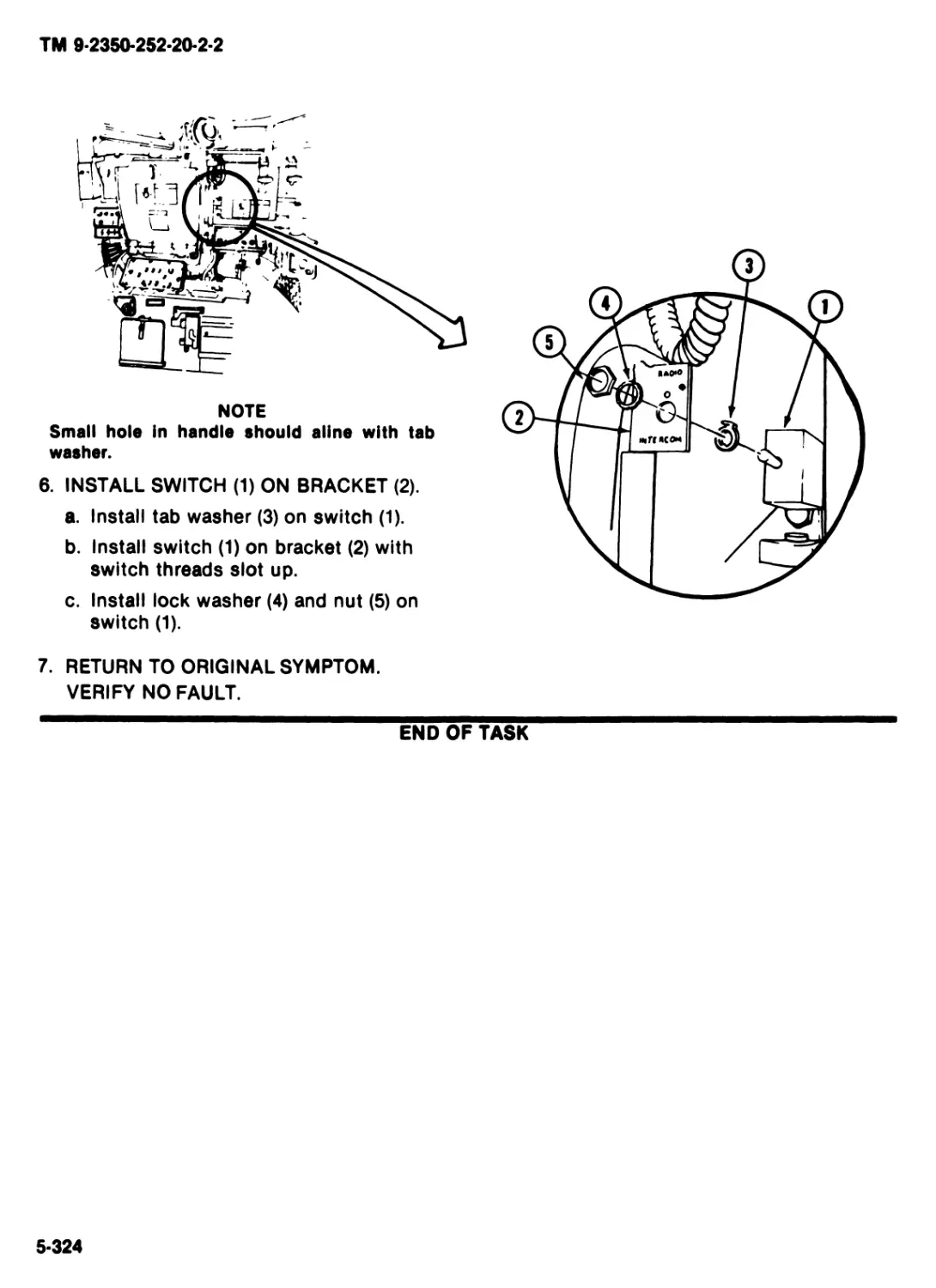
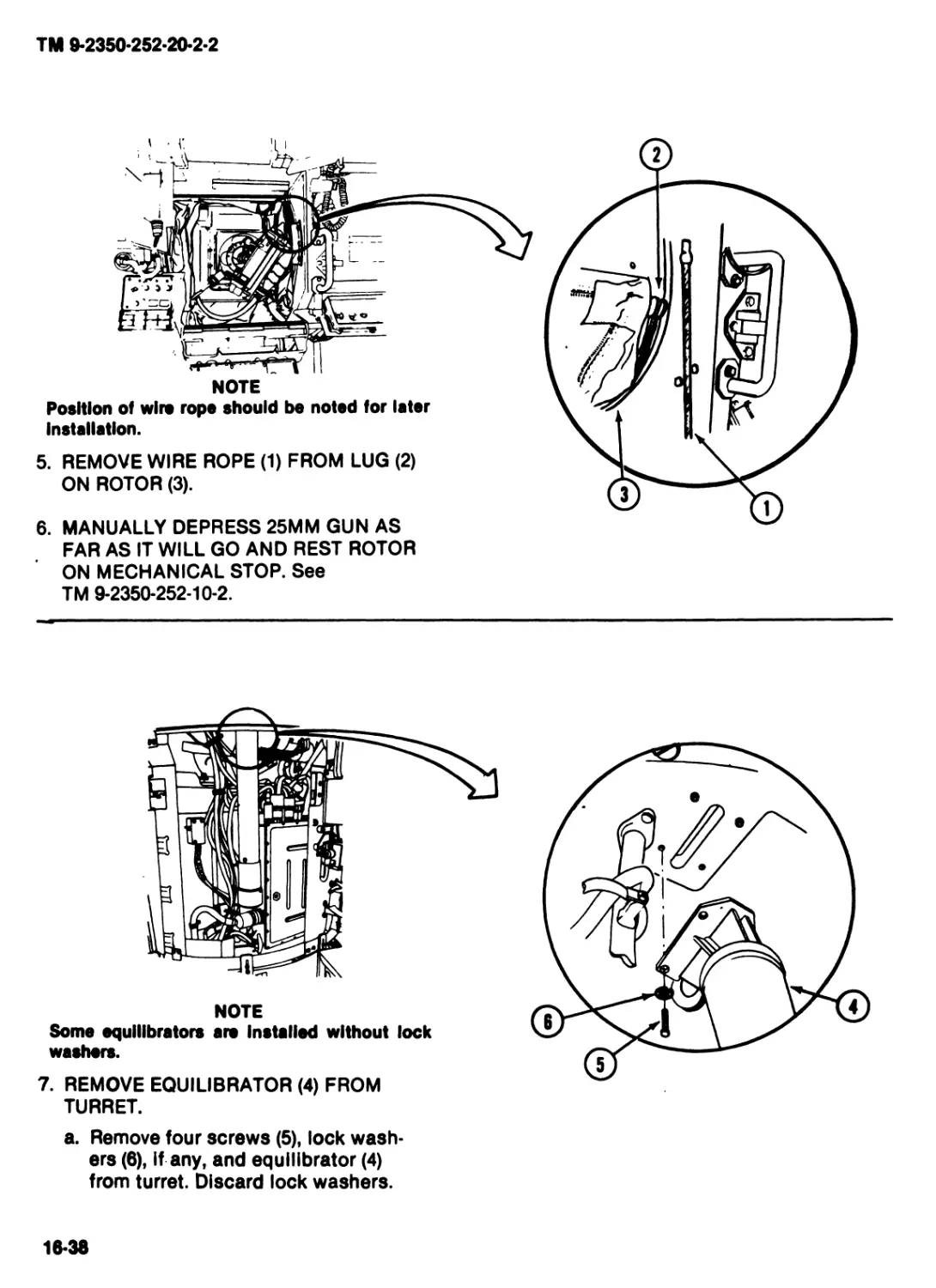
NOTE
Any marker or decal Is replaced the same way.
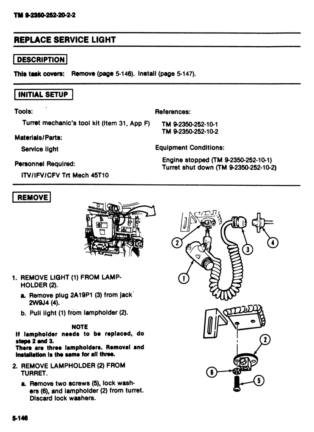
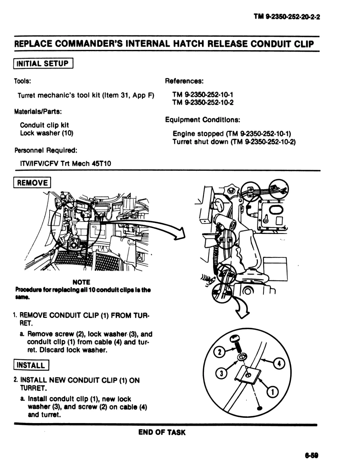
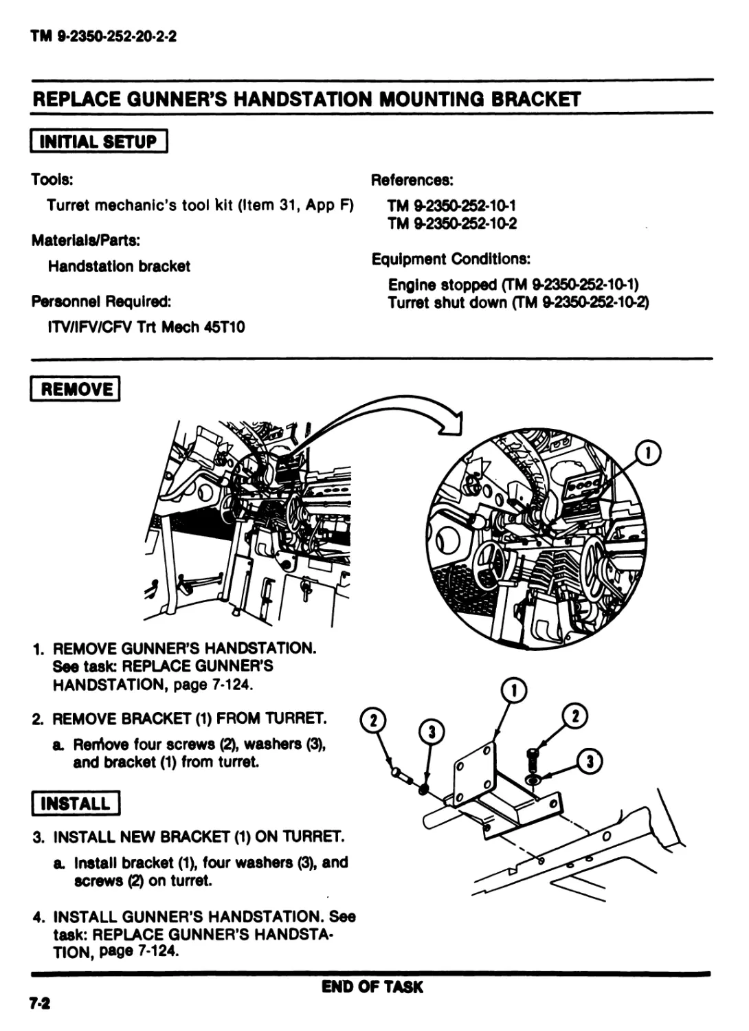
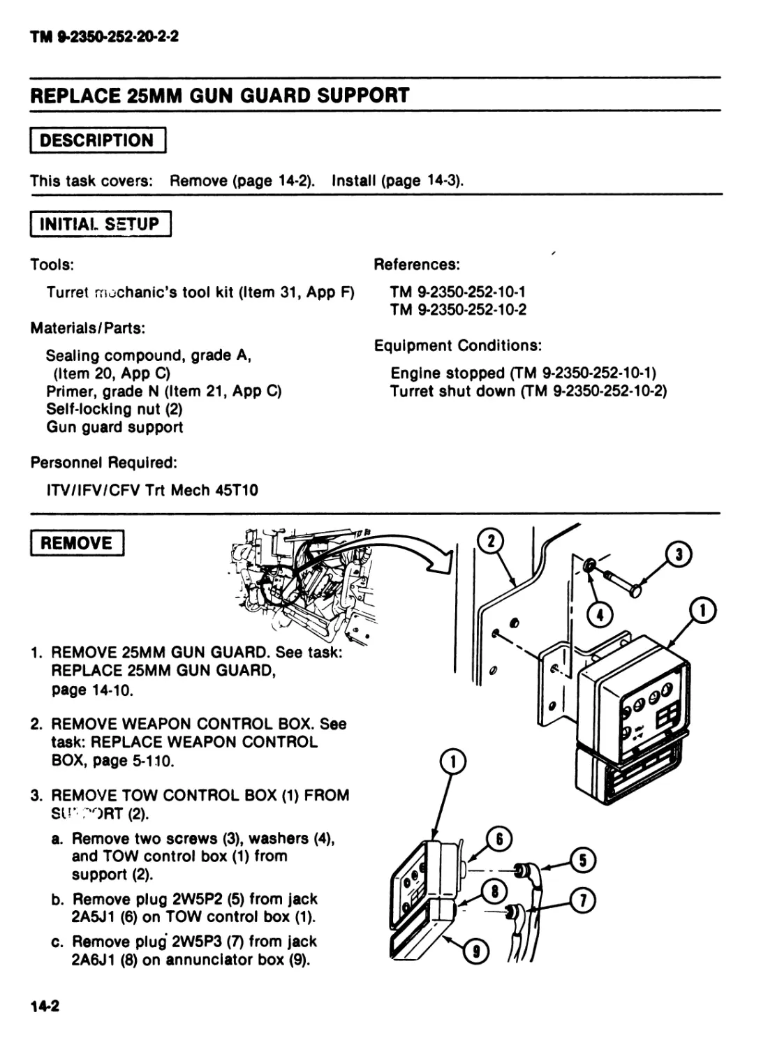
1. REMOVE MARKER OR DECAL (1) FROM
TURRET.
4-2
ТМ 9-2350-252-20-2-2
WARNING
Solvent fume* can bum and
could poison you. Road warn-
ing on front paga of this man-
ual.
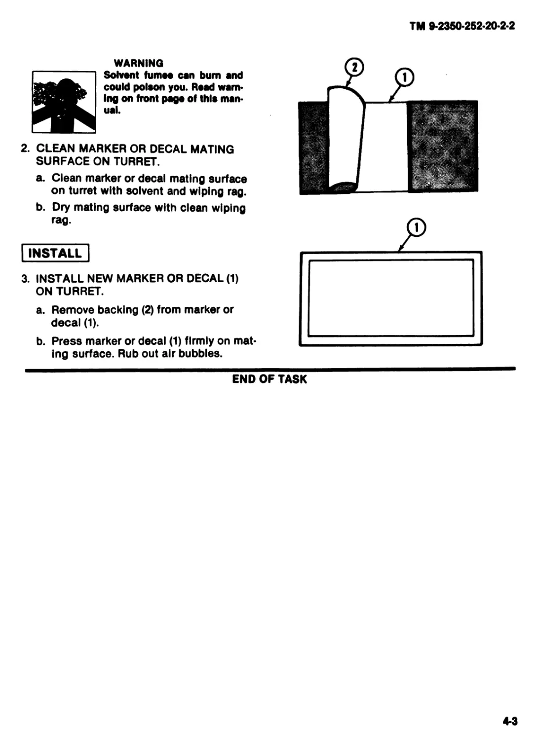
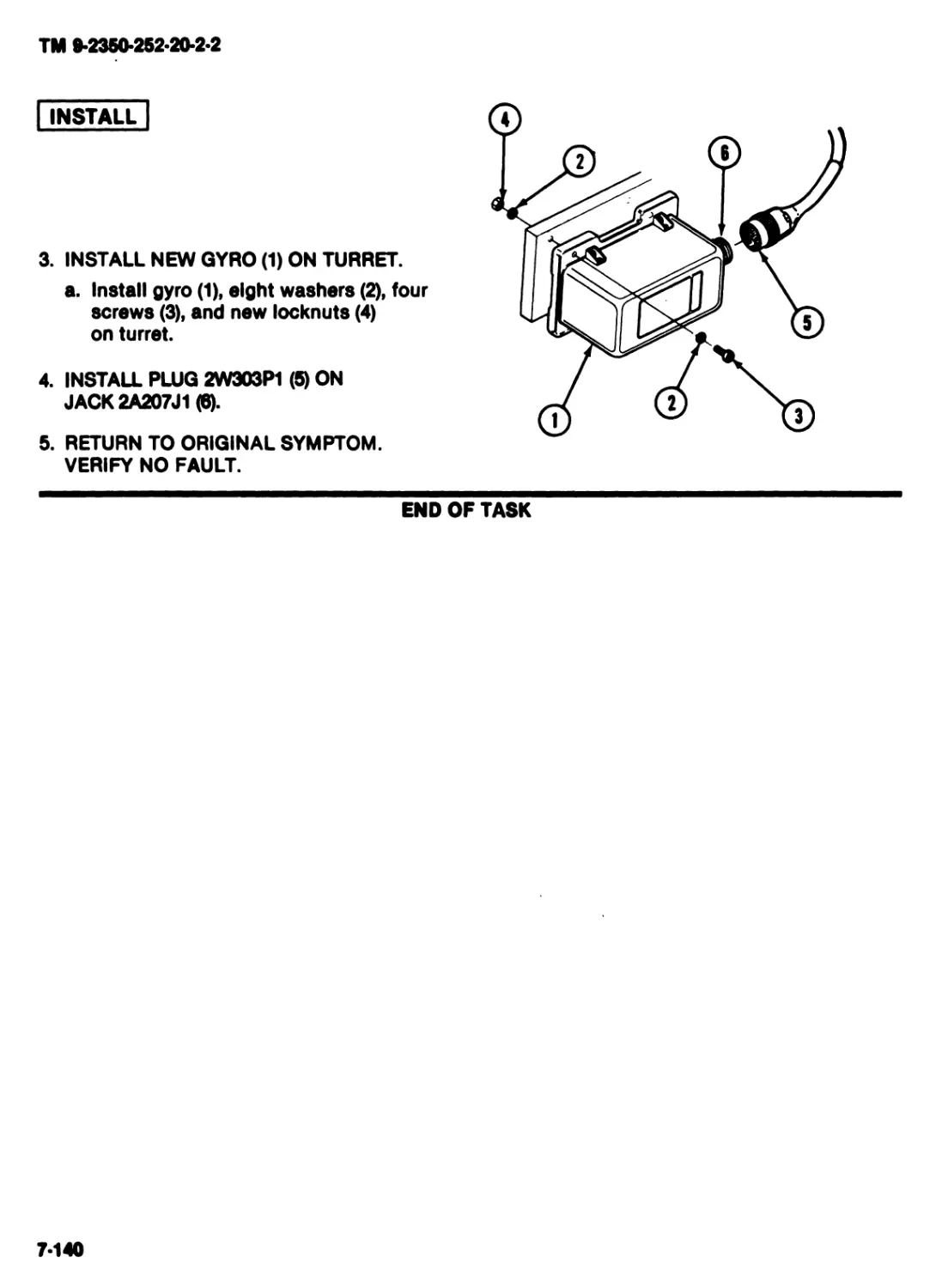
2. CLEAN MARKER OR DECAL MATING
SURFACE ON TURRET.
a. Clean marker or decal mating surface
on turret with solvent and wiping rag.
b. Dry mating surface with clean wiping
rag.
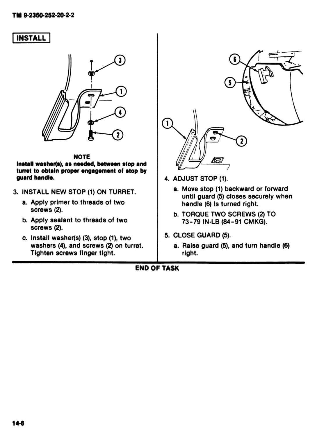
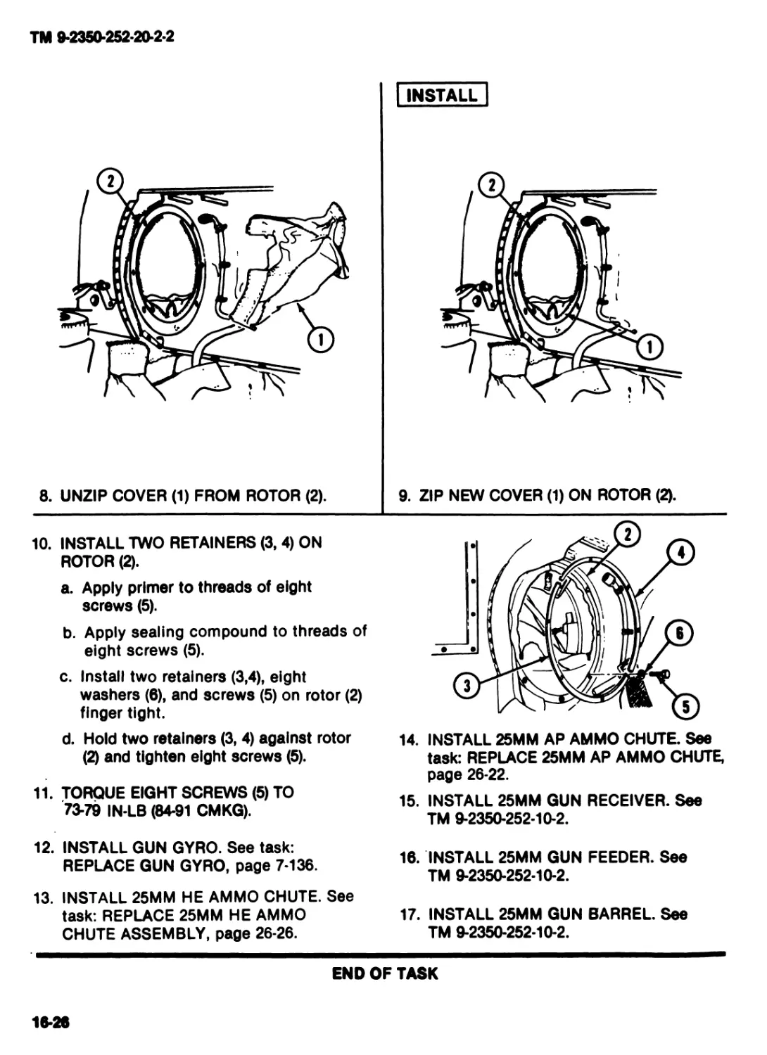
| INSTALL
3. INSTALL NEW MARKER OR DECAL (1)
ON TURRET.
a. Remove backing (2) from marker or
decal (1).
b. Press marker or decal (1) firmly on mat-
ing surface. Rub out air bubbles.
END OF TASK
4-3
TM 9-2350-252-20-2-2
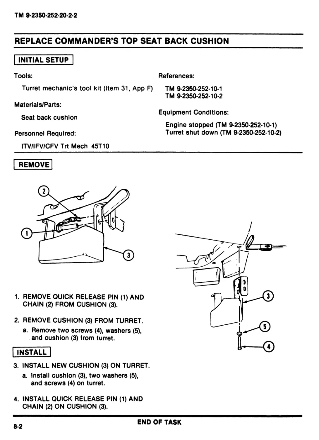
REPAIR LEAD
INITIAL SETUP
Personnel Required:
ITV/IFV/CFV Trt Meeh 45T10
References:
TM 9*2350-252-10*1
TM 9-2350-252-10-2
Equipment Conditions:
Engine stopped (TM 9-2350-252-10-1)
Turret shut down (TM 9-2350-252-10-2)
Lead removed from terminal
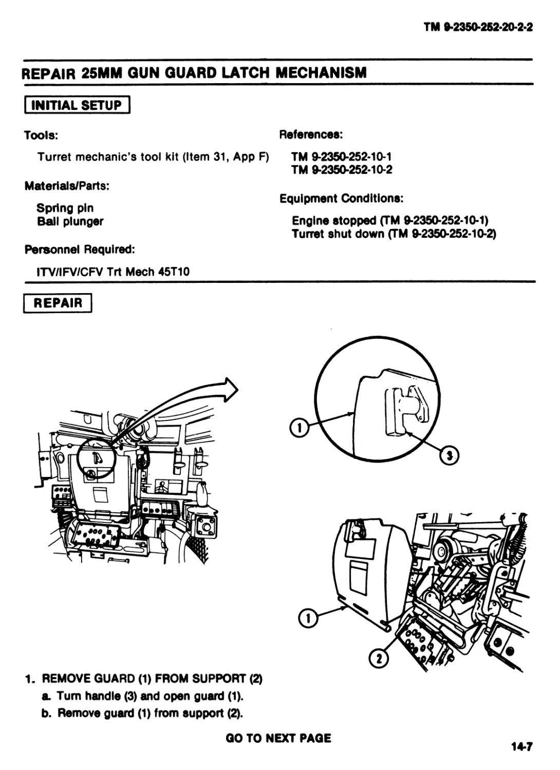
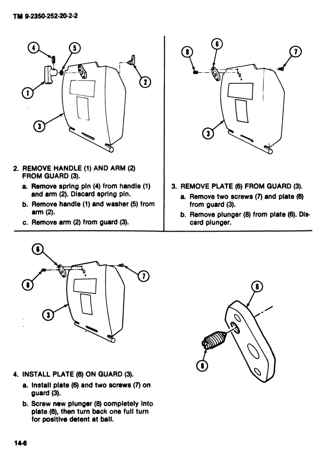
REPAIR
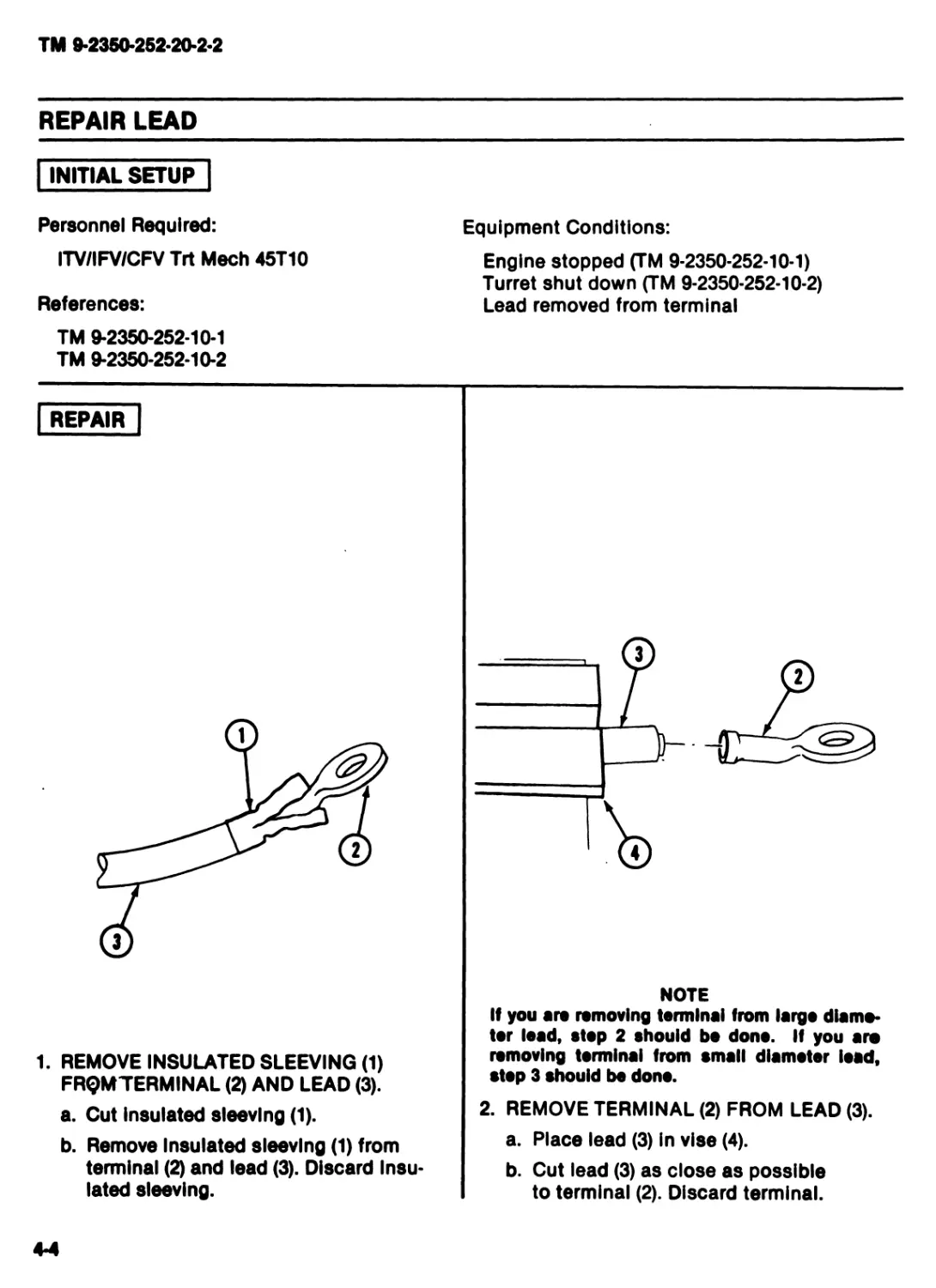
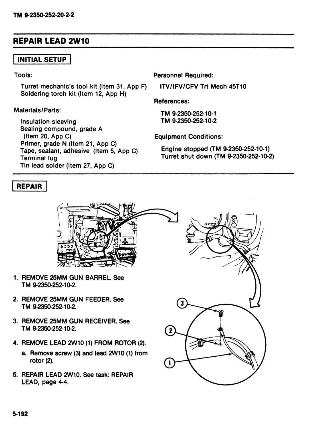
1. REMOVE INSULATED SLEEVING (1)
FRQMTERMINAL (2) AND LEAD (3).
a. Cut insulated sleeving (1).
b. Remove Insulated sleeving (1) from
terminal (2) and lead (3). Discard Insu-
lated sleeving.
NOTE
If you are removing terminal from largo diame-
ter lead, stop 2 should be dono. If you are
removing terminal from small diameter load,
stop 3 should be dono.
2. REMOVE TERMINAL (2) FROM LEAD (3).
a. Place lead (3) in vise (4).
b. Cut lead (3) as close as possible
to terminal (2). Discard terminal.
4-4
ТМ 9-2350-252-20-2-2
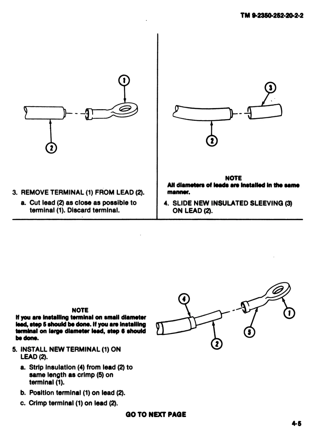
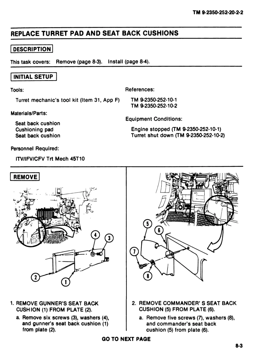
3. REMOVE TERMINAL (1) FROM LEAD (2).
a. Cut lead (2) as close as possible to
terminal (1). Discard terminal.
NOTE
AH diameters of loads are Installed In the same
manner.
4. SLIDE NEW INSULATED SLEEVING (3)
ON LEAD (2).
NOTE
H you ate Installing terminal on small diameter
lead, step S should be done. If you are Installing
terminal on largo diameter lead, step в should
bo done.
5. INSTALL NEW TERMINAL (1) ON
LEAD (2).
a. Strip Insulation (4) from lead (2) to
same length as crimp (5) on
terminal (1).
b. Position terminal (1) on lead (2).
c. Crimp terminal (1) on lead (2).
GO TO NEXT PAGE
4-5
TM 9-2350-252-20-2-2
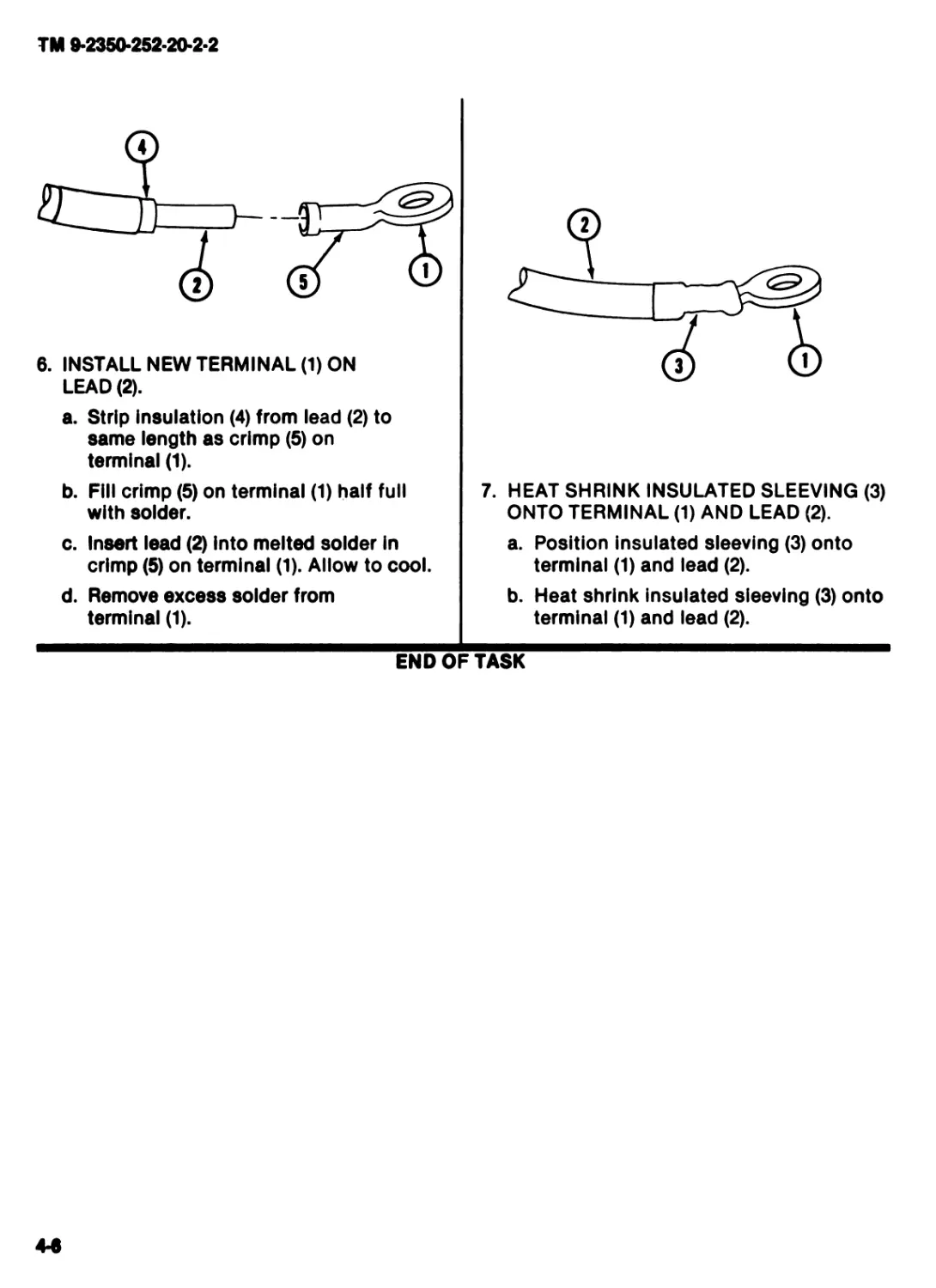
6. INSTALL NEW TERMINAL (1) ON
LEAD (2).
a. Strip Insulation (4) from lead (2) to
same length as crimp (5) on
terminal (1).
b. Fill crimp (5) on terminal (1) half full
with solder.
c. Insert lead (2) into melted solder In
crimp (5) on terminal (1). Allow to cool.
d. Remove excess solder from
terminal (1).
7. HEAT SHRINK INSULATED SLEEVING (3)
ONTO TERMINAL (1) AND LEAD (2).
a. Position insulated sleeving (3) onto
terminal (1) and lead (2).
b. Heat shrink insulated sleeving (3) onto
terminal (1) and lead (2).
END OF TASK
TM 9-2350-252-20-2-2
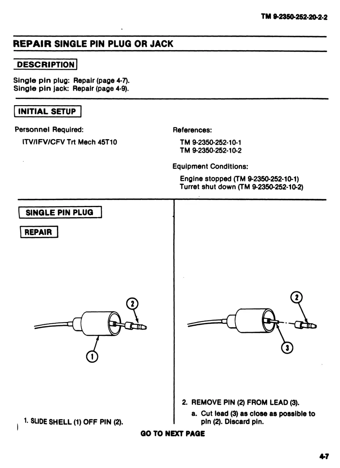
REPAIR SINGLE PIN PLUG OR JACK
DESCRIPTION
Single pin plug: Repair (page 4-7).
Single pin jack: Repair (page 4-9).
INITIAL SETUP
Personnel Required:
ITV/IFV/CFV Trt Meeh 45T10
References:
TM 9-2350-252-10-1
TM 9-2350-252-10-2
Equipment Conditions:
Engine stopped (TM 9-2350-252-10-1)
Turret shut down (TM 9-2350-252-10-2)
SINGLE PIN PLUG
REPAIR
1. SLIDE SHELL (1) OFF PIN (2).
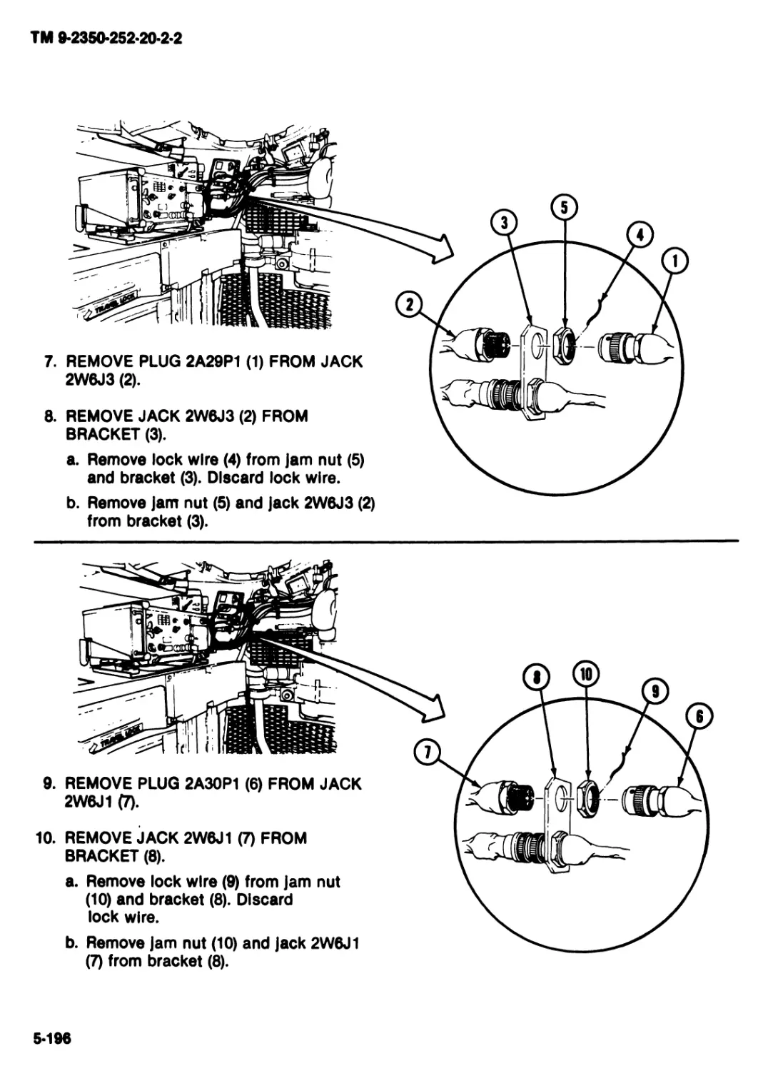
2. REMOVE PIN (2) FROM LEAD (3).
a. Cut lead (3) as close as possible to
pin (2). Discard pin.
GO TO NEXT PAGE
4*7
ТМ 9-2350-252-20-2-2
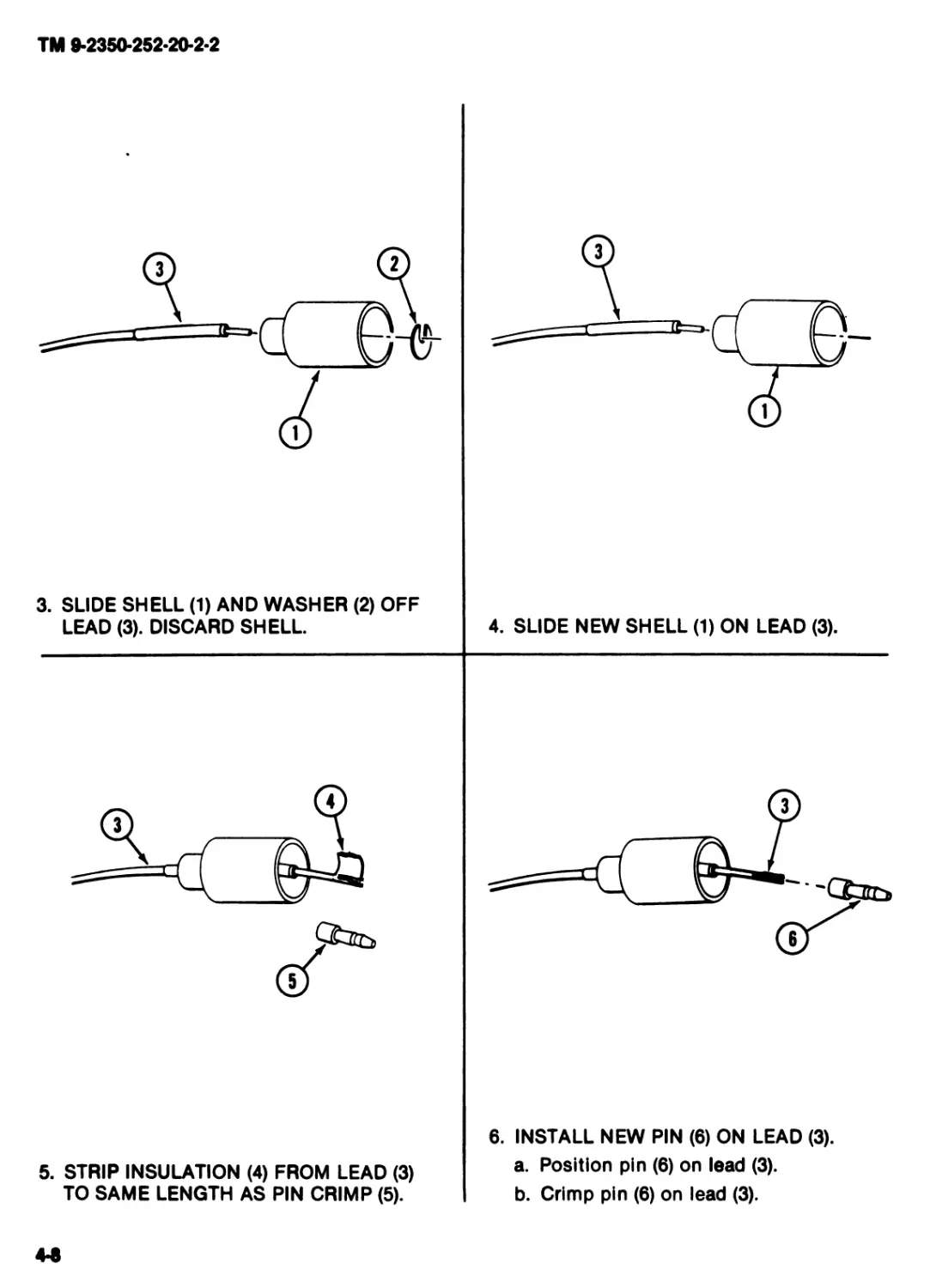
3. SLIDE SHELL (1) AND WASHER (2) OFF
LEAD (3). DISCARD SHELL
4. SLIDE NEW SHELL (1) ON LEAD (3).
5. STRIP INSULATION (4) FROM LEAD (3)
TO SAME LENGTH AS PIN CRIMP (5).
4-9
6. INSTALL NEW PIN (6) ON LEAD (3).
a. Position pin (6) on lead (3).
b. Crimp pin (6) on lead (3).
TM 9-2350-252-20-2-2
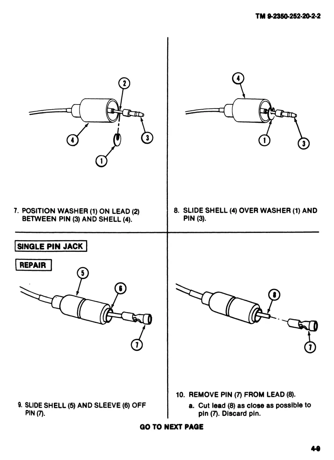
7. POSITION WASHER (1) ON LEAD (2)
BETWEEN PIN (3) AND SHELL (4).
8. SLIDE SHELL (4) OVER WASHER (1) AND
PIN (3).
SINGLE PIN JACK |
9. SLIDE SHELL (5) AND SLEEVE (6) OFF
PIN (7).
10. REMOVE PIN (7) FROM LEAD (8).
a. Cut lead (8) as close as possible to
pin (7). Discard pin.
GO TO NEXT PAGE
TM 9-2350-252-20-2-2
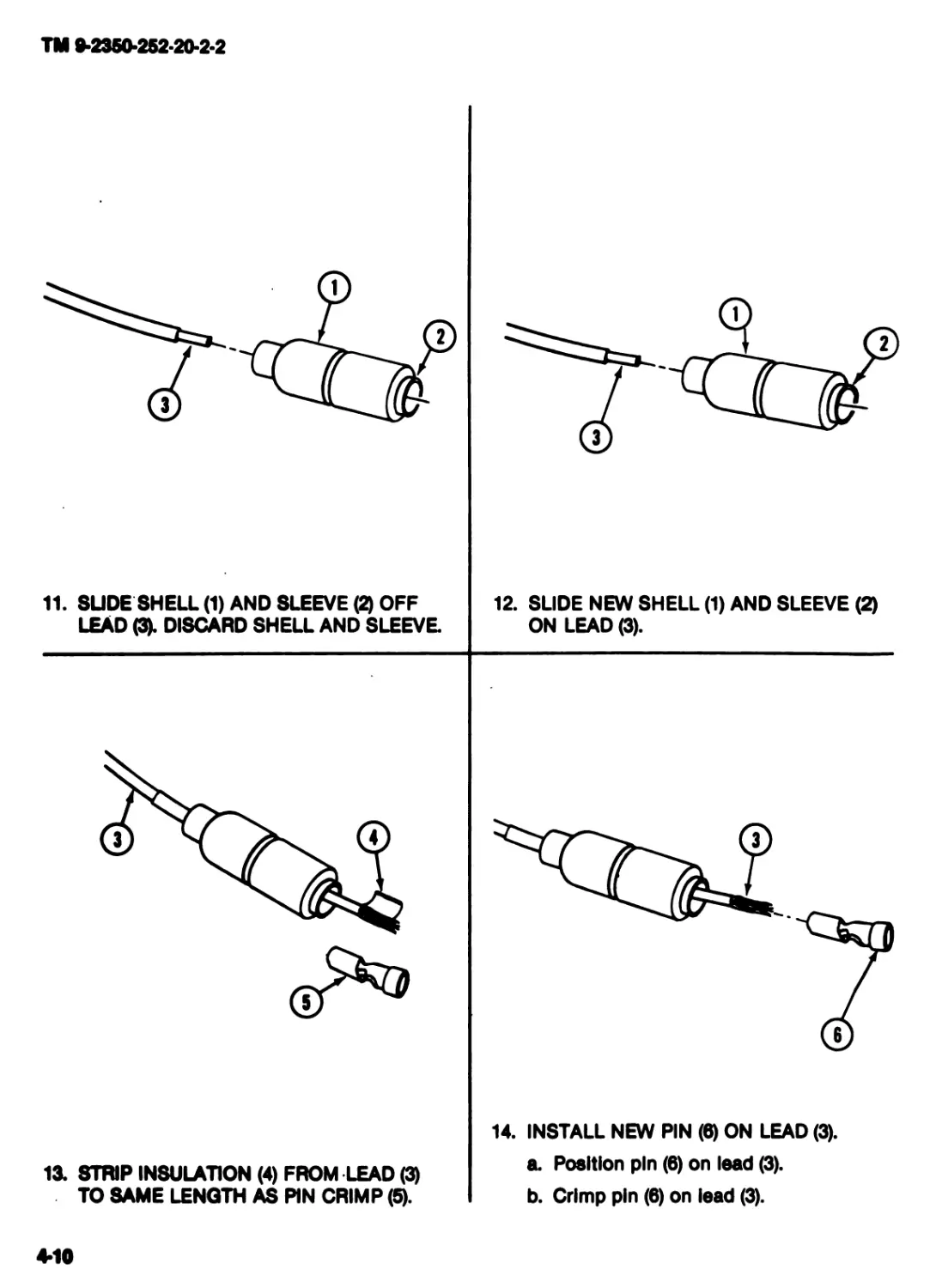
11. SLIDE SHELL (1) AND SLEEVE (2) OFF
LEAD (3). DISCARD SHELL AND SLEEVE
12. SLIDE NEW SHELL (1) AND SLEEVE (2)
ON LEAD (3).
13. STRIP INSULATION (4) FROM LEAD (3)
TO SAME LENGTH AS PIN CRIMP (5).
14. INSTALL NEW PIN (6) ON LEAD (3).
a. Position pin (6) on lead (3).
b. Crimp pin (6) on lead (3).
4-10
ТМ 9-2350-252-20-2-2
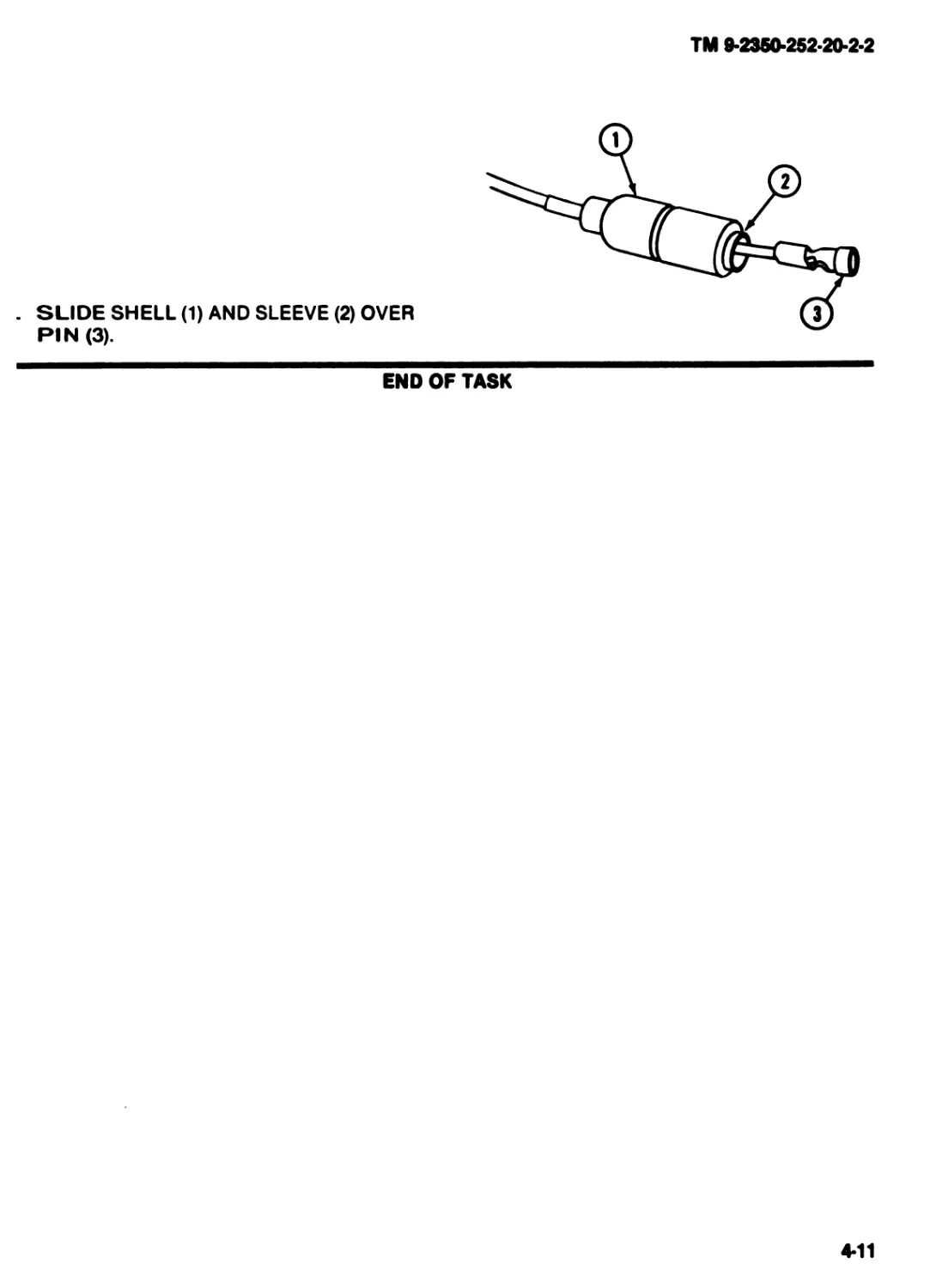
. SLIDE SHELL (1) AND SLEEVE (2) OVER
PIN (3).
END OF TASK
4*11
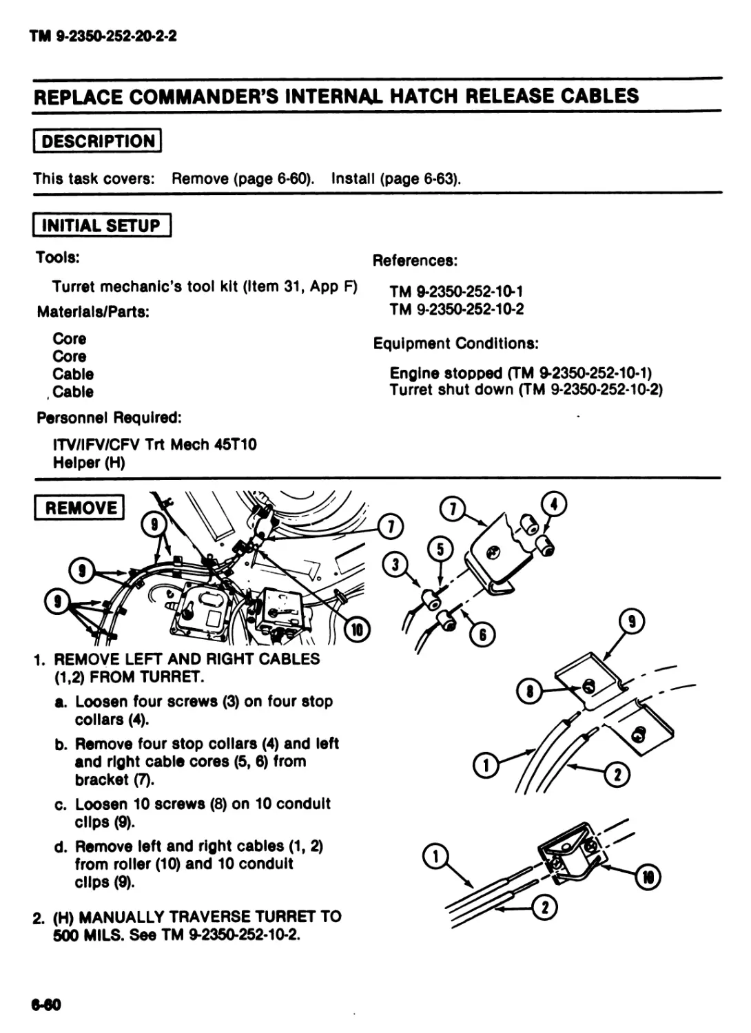
TM 9-2350-252-20-2-2
REPAIR MULTIPIN PLUG/JACK, RUBBER TYPE
DESCRIPTION
This task covers: Repair multipin plug (4-12). Replace multipin jack (page 4-14).
| INITIAL SETUP"
Personnel Required:
ITV/IFV/CFV Trt Meeh 45T10
References:
TM 9-2350-252-10-1
TM 9-2350-252-10-2
Equipment Conditions:
Engine stopped (TM 9-2350-252-10-1)
Turret shut down (TM 9-2350-252-10-2)
MULTIPIN PLUG
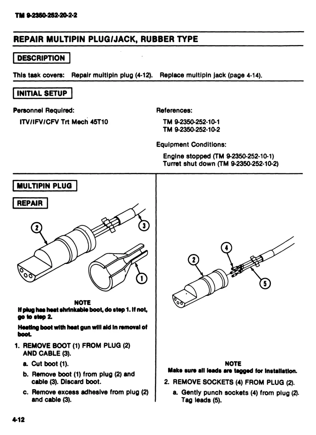
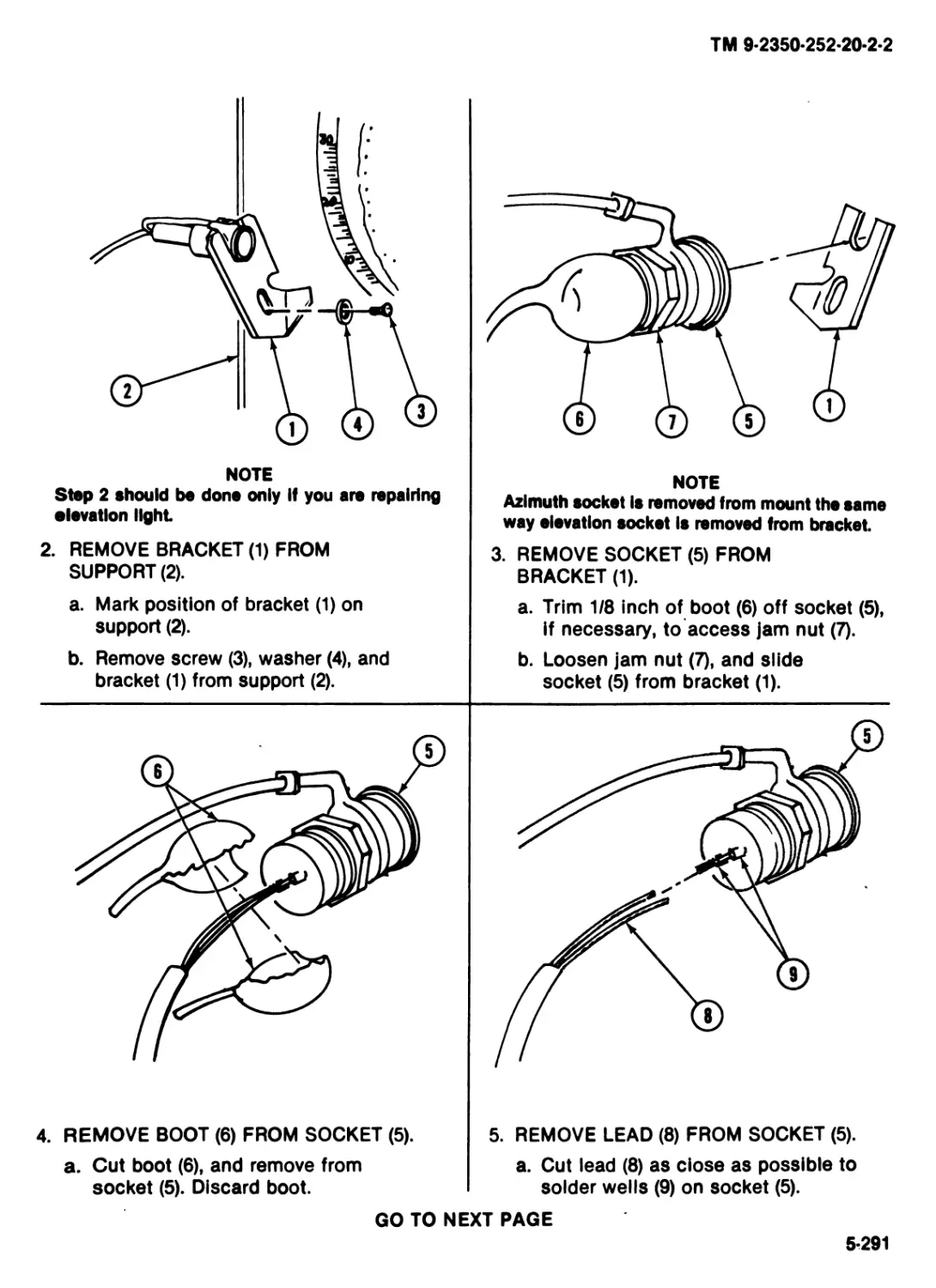
NOTE
If plug has heat shrinkable boot, do stopl.lf not,
go Io stop 2.
Hooting boot with heat gun will aid In removal of
boot
1. REMOVE BOOT (1) FROM PLUG (2)
AND CABLE (3).
a. Cut boot (1).
b. Remove boot (1) from plug (2) and
cable (3). Discard boot.
c. Remove excess adhesive from plug (2)
and cable (3).
NOTE
Maks sure all loads ars tagged for Installation.
2. REMOVE SOCKETS (4) FROM PLUG (2).
a. Gently punch sockets (4) from plug (2).
Tag leads (5).
4*12
TM 9*2350*2S2*20*2*2
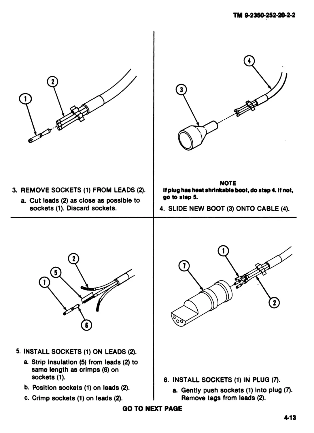
3. REMOVE SOCKETS (1) FROM LEADS (2).
a. Cut leads (2) as close as possible to
sockets (1). Discard sockets.
NOTE
If plug has heat shrinkable boot, do step 4. If not,
go to step 5.
4. SLIDE NEW BOOT (3) ONTO CABLE (4).
5. INSTALL SOCKETS (1) ON LEADS (2).
a Strip insulation (5) from leads (2) to
same length as crimps (6) on
sockets (1).
b. Position sockets (1) on leads (2).
c. Crimp sockets (1) on leads (2).
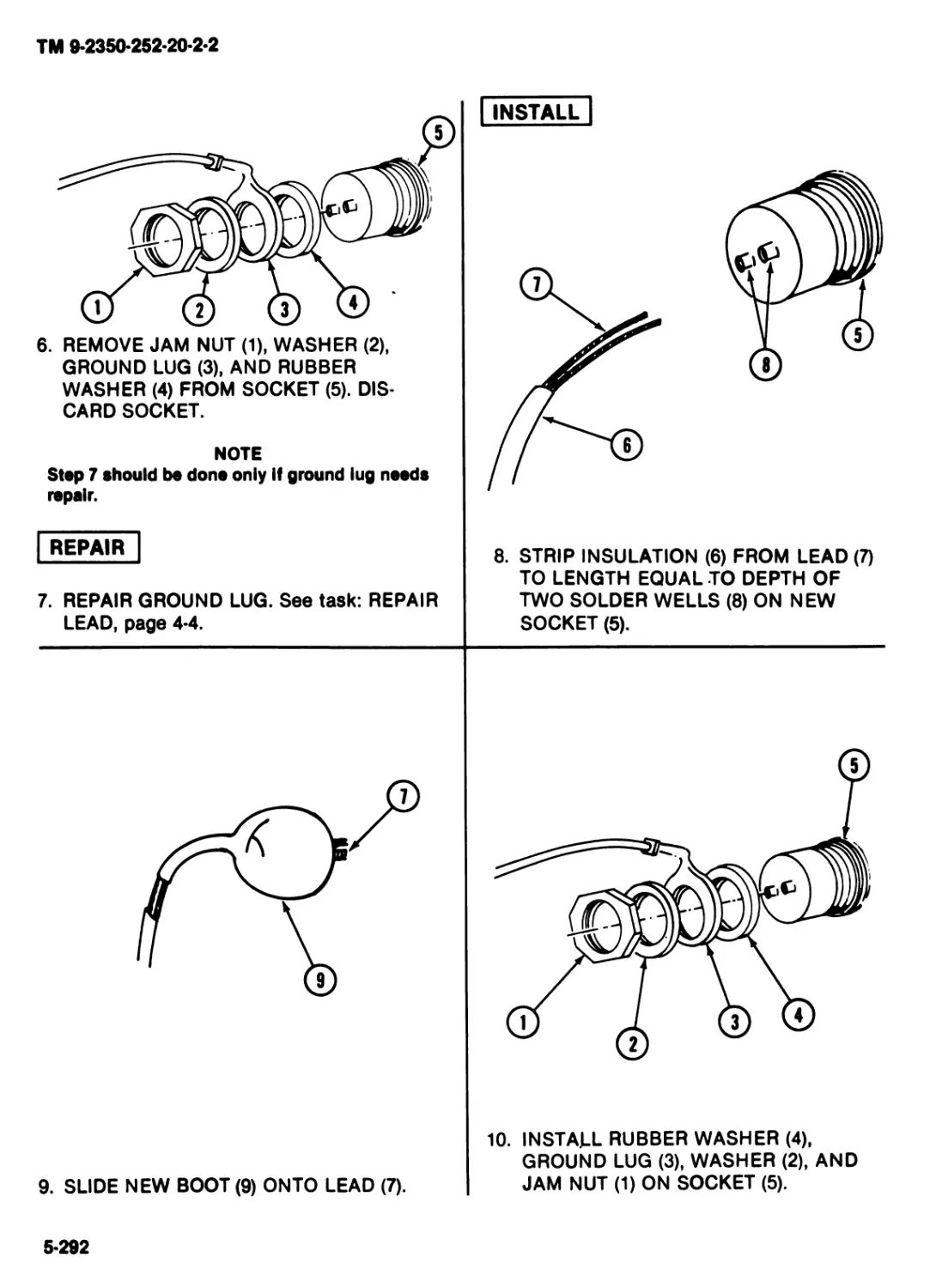
6. INSTALL SOCKETS (1) IN PLUG (7).
a. Gently push sockets (1) Into plug (7).
Remove tags from leads (2).
GO TO NEXT PAGE
4*13
TM 9-2350-252-20-2-2
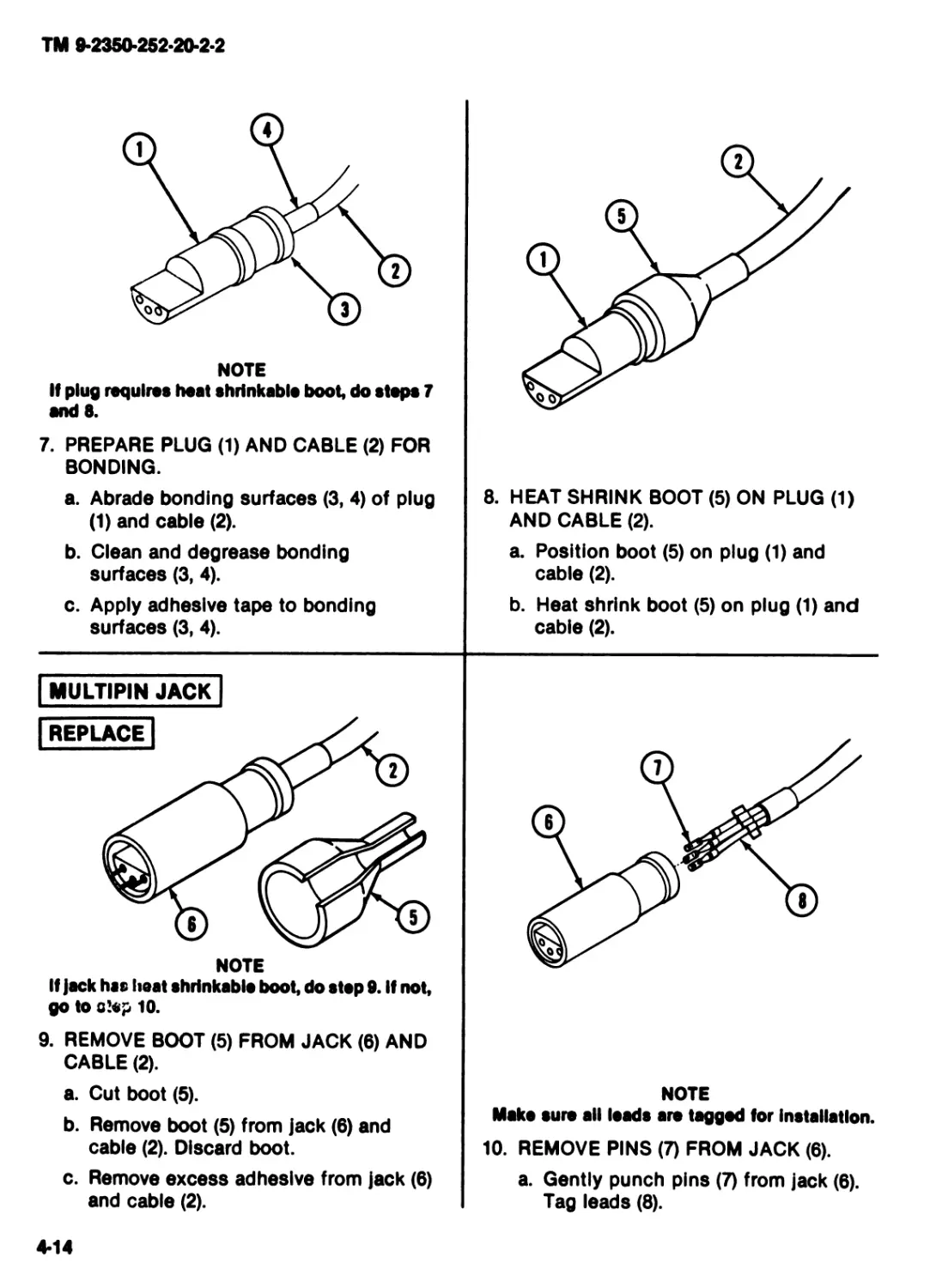
NOTE
If plug requires heat shrinkable boot, do steps 7
and 8.
7. PREPARE PLUG (1) AND CABLE (2) FOR
BONDING.
a. Abrade bonding surfaces (3,4) of plug
(1) and cable (2).
b. Clean and degrease bonding
surfaces (3, 4).
c. Apply adhesive tape to bonding
surfaces (3, 4).
8. HEAT SHRINK BOOT (5) ON PLUG (1)
AND CABLE (2).
a. Position boot (5) on plug (1) and
cable (2).
b. Heat shrink boot (5) on plug (1) and
cable (2).
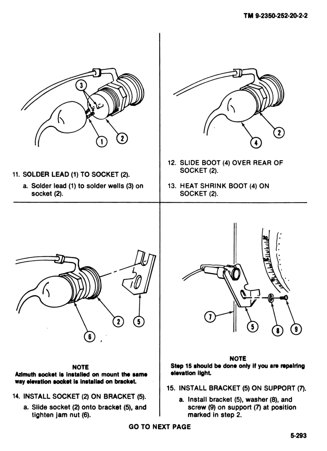
MULTIPIN JACK
NOTE
If Jack has heat shrinkable boot, do step 9. If not,
go to step 10.
9. REMOVE BOOT (5) FROM JACK (6) AND
CABLE (2).
a. Cut boot (5).
b. Remove boot (5) from jack (6) and
cable (2). Discard boot.
c. Remove excess adhesive from jack (6)
and cable (2).
NOTE
Make sure all leads are tagged for Installation.
10. REMOVE PINS (7) FROM JACK (6).
a. Gently punch pins (7) from jack (8).
Tag leads (8).
4-14
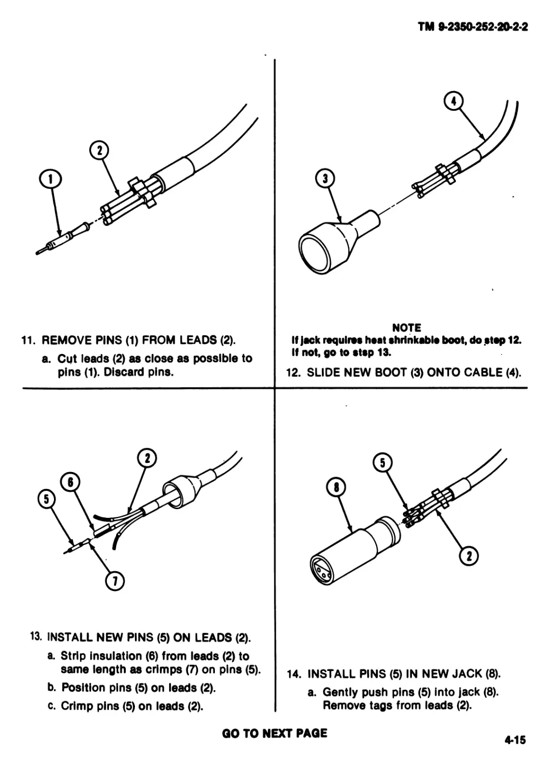
ТМ 9-2350*252-20*2-2
11. REMOVE PINS (1) FROM LEADS (2).
a. Cut leads (2) as close as possible to
pins (1). Discard pins.
NOTE
If jack requires heat shrinkable boot, do .step 12.
If not, go to stsp 13.
12. SLIDE NEW BOOT (3) ONTO CABLE (4).
13. INSTALL NEW PINS (5) ON LEADS (2).
a. Strip insulation (6) from leads (2) to
same length as crimps (7) on pins (5).
b. Position pins (5) on leads (2).
c. Crimp pins (5) on leads (2).
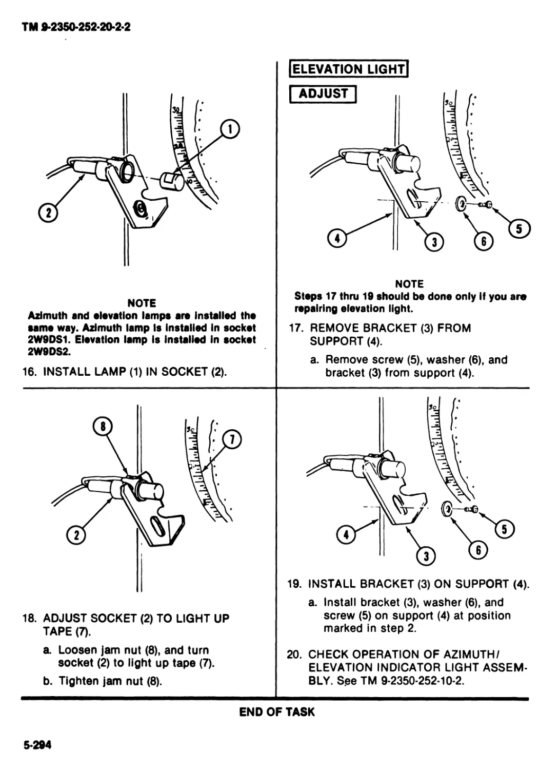
14. INSTALL PINS (5) IN NEW JACK (8).
a. Gently push pins (5) into jack (8).
Remove tags from leads (2).
GO TO NEXT PAGE
4*15
TM 9-2350-252-20-2-2
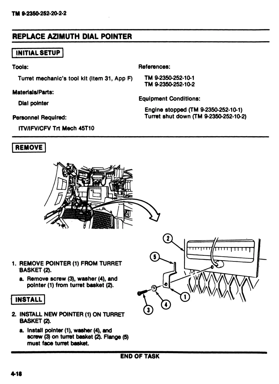
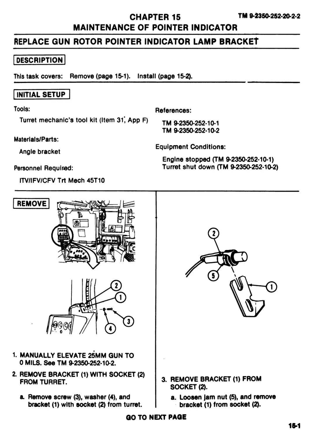
REPLACE AZIMUTH DIAL POINTER
INITIAL SETUP
Tools:
References:
Turret mechanic's tool kit (Item 31, App F)
Materlals/Parts:
Dial pointer
Personnel Required:
TM 9-2350-252-10-1
TM 9-2350-252-10-2
Equipment Conditions:
Engine stopped (TM 9-2350-252-10-1)
Turret shut down (TM 9-2350-252-10-2)
ITV/IFV/CFV Trt Meeh 45T10
REMOVE
1. REMOVE POINTER (1) FROM TURRET
BASKET (2).
a. Remove screw (3), washer (4), and
pointer (1) from turret basket (2).
INSTALL
2. INSTALL NEW POINTER (1) ON TURRET
BASKET (2).
a. Install pointer (1), washer (4), and
screw (3) on turret basket (2). Flange (5)
must face turret basket.
END OF TASK
4-18
TM 9-2360-2S2-20-2-2
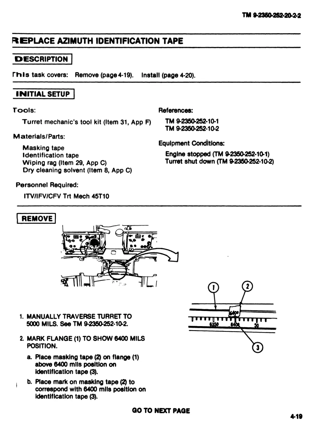
REPLACE AZIMUTH IDENTIFICATION TAPE
description"
Г111 s task covers: Remove (page 4-19). I nstall (page 4-20).
INITIAL SETUP"
Tools: References:
Turret mechanic’s tool kit (Item 31, App F) TM 9-2350-252-10-1
TM 9-2350-252-10-2
Materials/Parts:
., ,. Equipment Conditions:
Masking tape
Identification tape Engine stopped (TM 9-2350-252-10-1)
Wiping rag (Item 29, Арр C) Turret shut down 9-2350-252-10-2)
Dry cleaning solvent (Item 8, Арр C)
Personnel Required:
ITV/IFV/CFV Trt Meeh 45T10
REMOVE
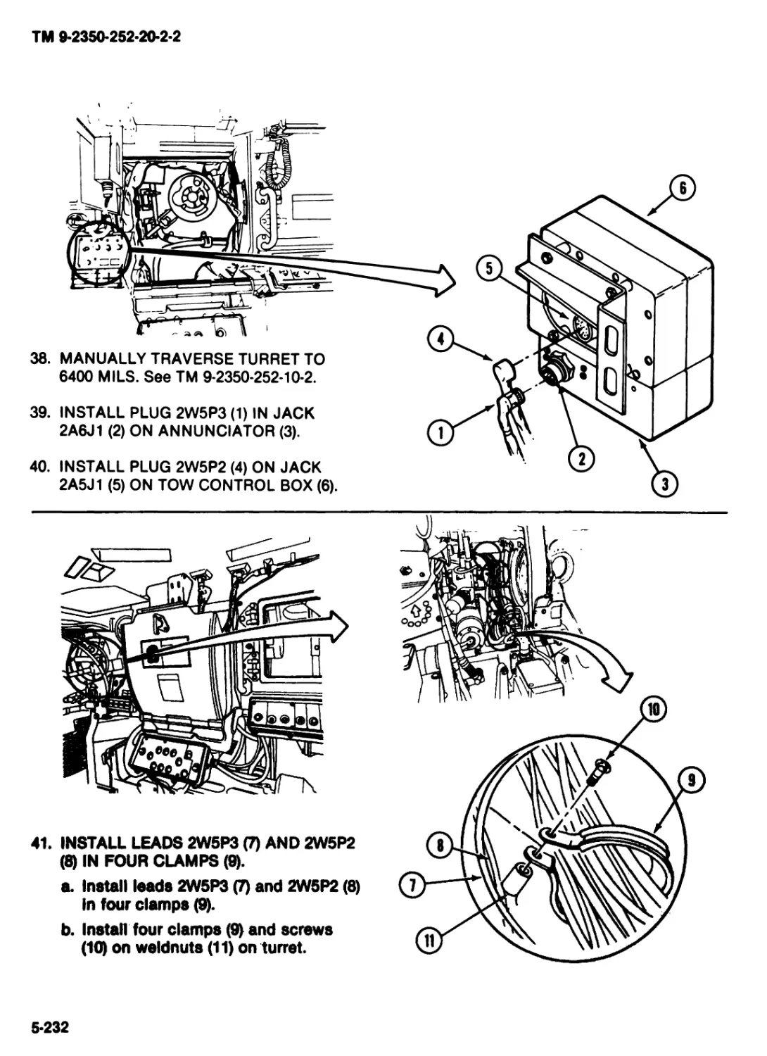
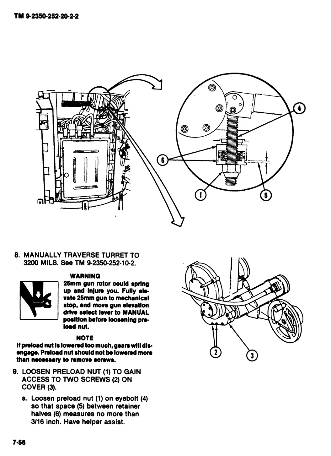
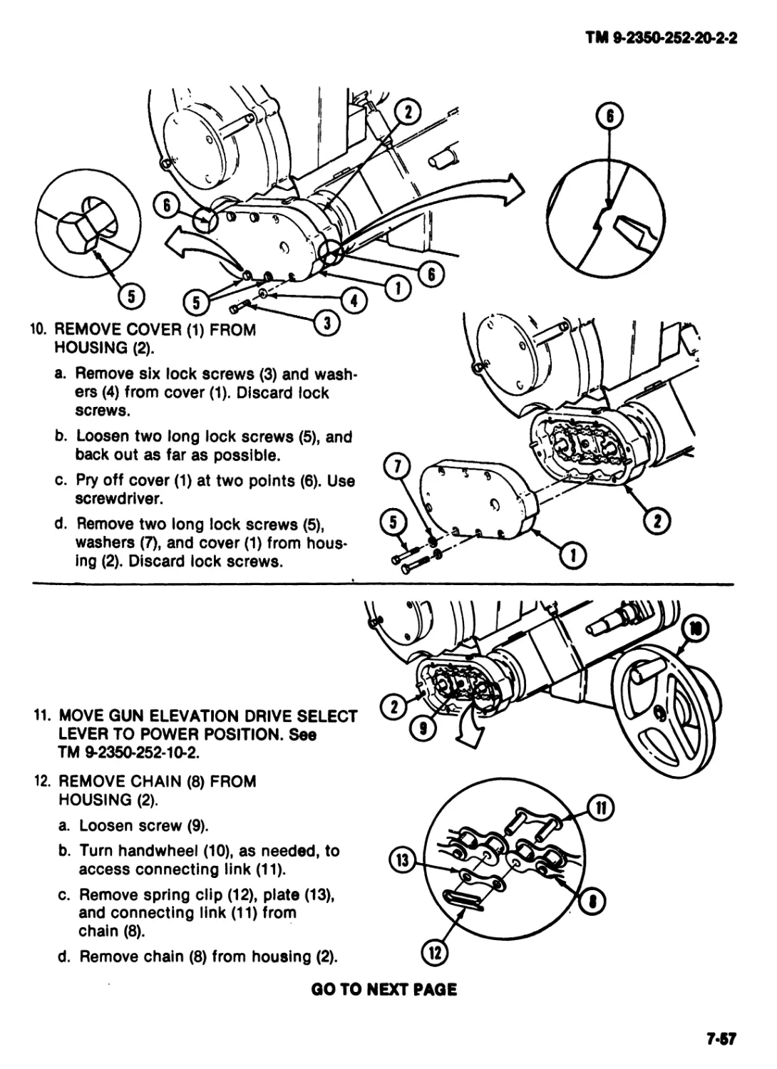
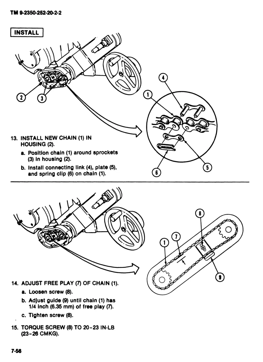
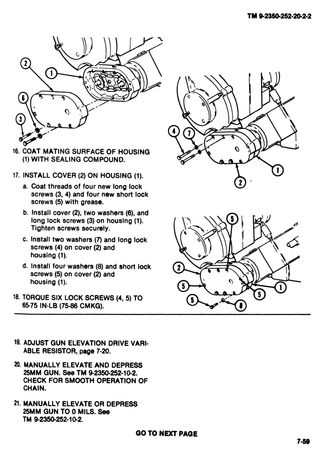
I a* «LeaJirp •£_ 1. MANUALLY TRAVERSE TURRET TO qr 5000 MILS. See TM 9-2350-252-10-2. e 2. MARK FLANGE (1) TO SHOW 6400 MILS POSITION. a. Place masking tape (2) on flange (1) above 6400 mils position on Identification tape (3). b. Place mark on masking tape (2) to correspond with 6400 mils position on Identification tape (3). Ф JD ti 11Ц11 iffi । гт~] 11— — HF W Q)
GO TO NEXT PAGE
4-19
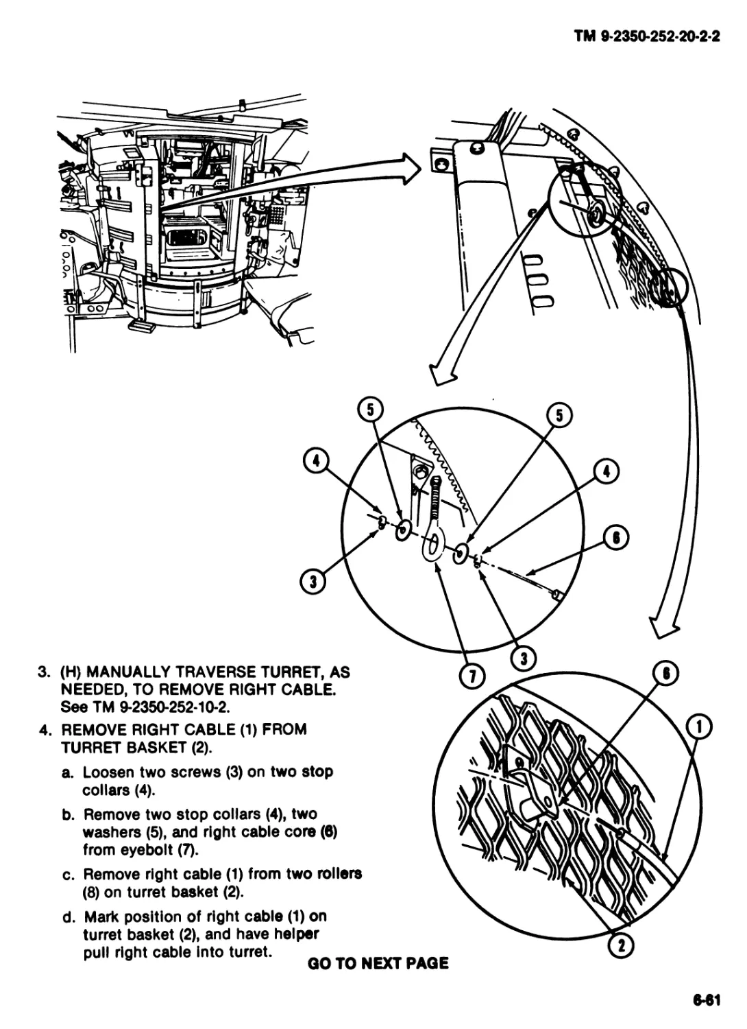
ТМ 9-2360-252-20-2-2
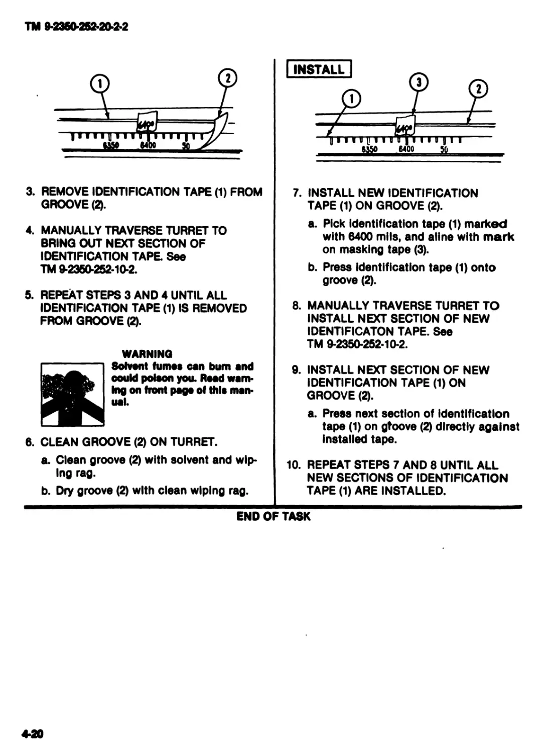
3. REMOVE IDENTIFICATION TAPE (1) FROM
GROOVE (2).
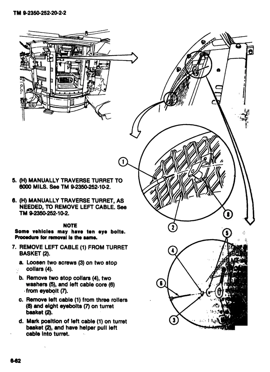
4. MANUALLY TRAVERSE TURRET TO
BRING OUT NEXT SECTION OF
IDENTIFICATION TAPE. See
TM 9-2360-252-10-2.
5. REPEAT STEPS 3 AND 4 UNTIL ALL
IDENTIFICATION TAPE (1) IS REMOVED
FROM GROOVE (2).
WARNING
Solvent fumes can bum and
could poison you. Road warn-
ing on front page of this man-
ual.
6. CLEAN GROOVE (2) ON TURRET.
a. Clean groove (2) with solvent and wip-
ing rag.
b. Dry groove (2) with clean wiping rag.
7. INSTALL NEW IDENTIFICATION
TAPE (1) ON GROOVE (2).
a. Pick Identification tape (1) marked
with 6400 mils, and aline with mark
on masking tape (3).
b. Press identification tape (1) onto
groove (2).
8. MANUALLY TRAVERSE TURRET TO
INSTALL NEXT SECTION OF NEW
IDENTIFICATON TAPE. See
TM 9-2350-252-10-2.
9. INSTALL NEXT SECTION OF NEW
IDENTIFICATION TAPE (1) ON
GROOVE (2).
a. Press next section of identification
tape (1) on gtoove (2) directly against
Installed tape.
10. REPEAT STEPS 7 AND 8 UNTIL ALL
NEW SECTIONS OF IDENTIFICATION
TAPE (1) ARE INSTALLED.
END OF TASK
4-20
TM 9-2350-252-20-2-2
Section III. MAINTENANCE OF TURRET BASKET
TASK INDEX
Task Pape Task Page
Replace Turret Floor Plates..4*22 Replace Turret Basket Ground Strap .... 4-28
Replace Slip Ring Replace Snap Fastener Stud .4-30
Rigid Connecting Link .......4-23
Replace Turret Basket Loose Items
Stop Plate.................4-26
4*21
TM 9-2350-252-20-2-2
REPLACE TURRET FLOOR PLATES
INITIAL SETUP
Tools:
References:
Turret mechanic's tool kit (Item 31, App F) TM 9-2350*252*10-1
TM 9-2350-252-10*2
Personnel Required:
ITV/IFV/CFV Trt Meeh 45T10 Equipment Conditions:
Engine stopped (TM 9-2350-252-10*1)
Turret shut down (TM 9-2350-252-10-2)
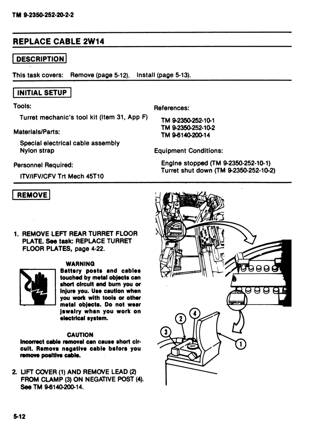
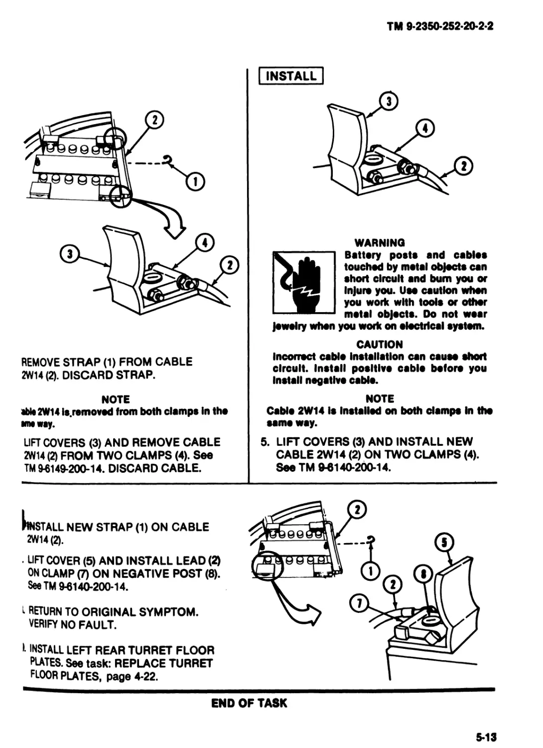
REMOVE
WARNING
Battery posts and cables
touched by metal objects can
short circuit and bum you or
Injure you. Use caution whon
you work with tools or other
metal objects. Do not wear
jewelry when you work on electrical system.
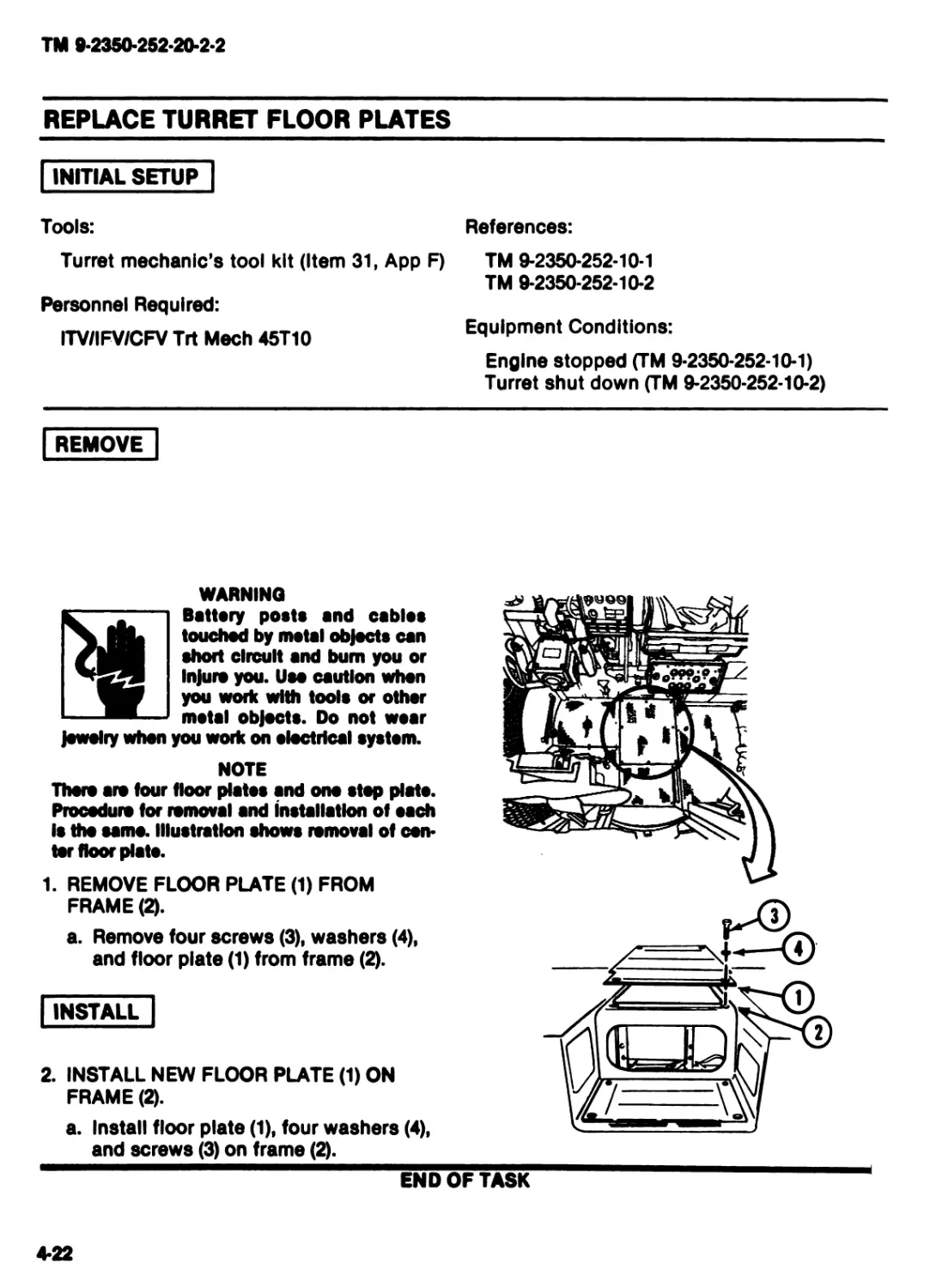
NOTE
There are four floor plates and ono stop plato.
Procedure for removal and installation of each
Is the same. Illustration shows removal of cen-
ter floor plate.
1. REMOVE FLOOR PLATE (1) FROM
FRAME (2).
a. Remove four screws (3), washers (4),
and floor plate (1) from frame (2).
INSTALL
2. INSTALL NEW FLOOR PLATE (1) ON
FRAME (2).
a. Install floor plate (1), four washers (4),
and screws (3) on frame (2).
END OF TASK
4-22
TM 9-2350-252-20-2-2
REPLACE SLIP RING RIGID CONNECTING LINK
DESCRIPTION
his task covers: Remove (page 4*23). install (page 4-24).
INITIAL SETUP
ools:
Turret mechanic’s tool kit (Item 31, App F)
Haterials/Parts:
Self-locking bolt (2)
Rigid connecting link
Personnel Required:
ITV/IFV/CFV Trt Meeh 45T10
References:
TM 9-2350-252-10*1
TM 9-2350-252-10-2
TM 9-2350-252-20-1
Equipment Conditions:
Engine stopped (TM 9-2350-252-10-1)
Turret shut down (TM 9-2350-252-10-2)
REMOVE
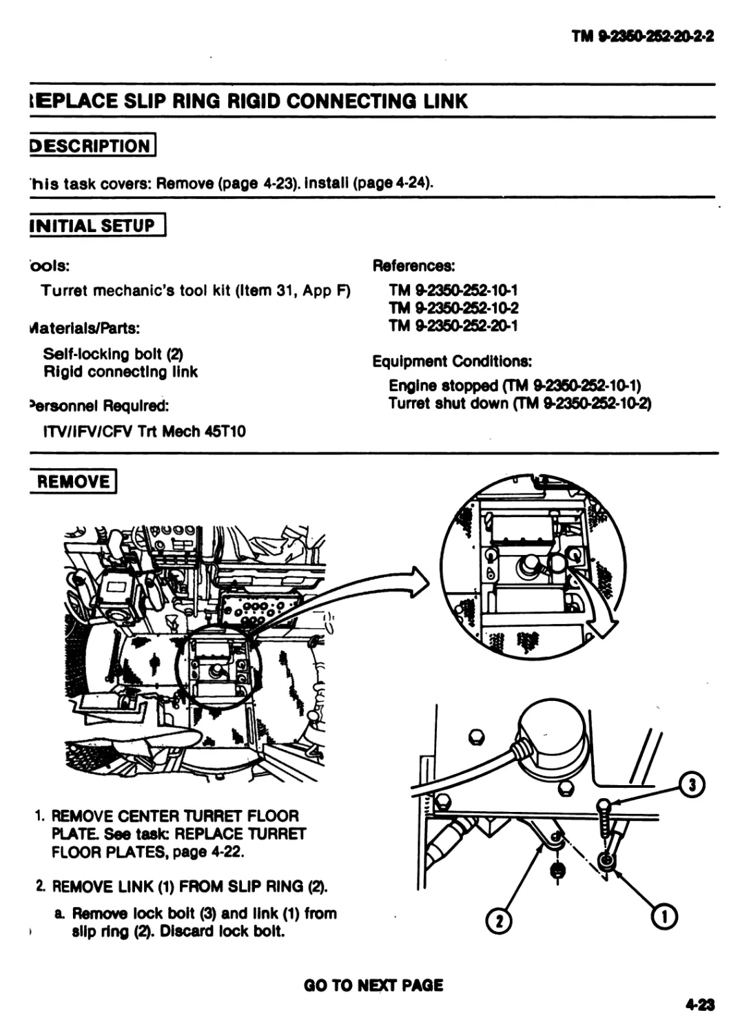
2. REMOVE LINK (1) FROM SLIP RING (2).
a Remove lock bolt (3) and link (1) from
slip ring (2). Discard lock bolt.
1. REMOVE CENTER TURRET FLOOR
PLATE See task: REPLACE TURRET
FLOOR PLATES, page 4-22.
GO TO NEXT PAGE
4*23
ТМ 9-2350-252-20-2-2
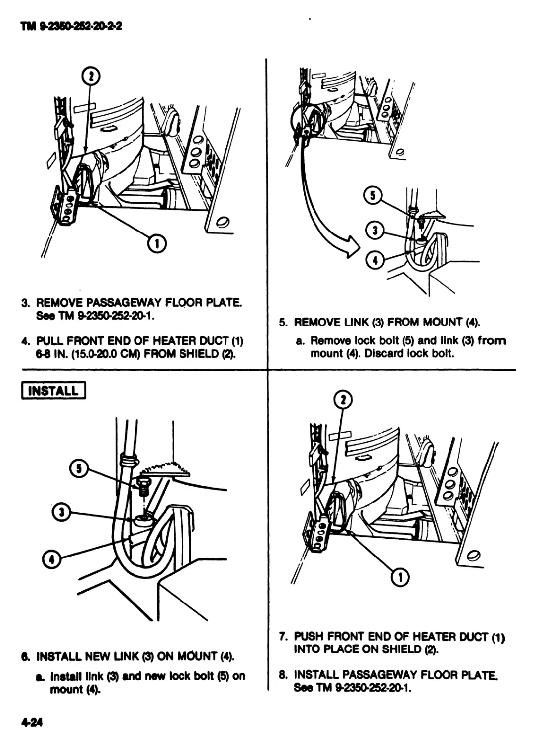
3. REMOVE PASSAGEWAY FLOOR PLATE
See TM 9-2350-252-20-1.
4. PULL FRONT END OF HEATER DUCT (1)
6-8 IN. (15.0-20.0 CM) FROM SHIELD (2).
5. REMOVE LINK (3) FROM MOUNT (4).
a. Remove lock bolt (5) and link (3) from
mount (4). Discard lock bolt.
I INSTALL |
8. INSTALL NEW LINK (3) ON MOUNT (4).
a. Install link and new lock bolt (5) on
mount (4).
7. PUSH FRONT END OF HEATER DUCT (1)
INTO PLACE ON SHIELD (2).
8. INSTALL PASSAGEWAY FLOOR PLATE
See TM 9*2350-252-20-1.
4-24
TM 9-2350-252-20-2-2
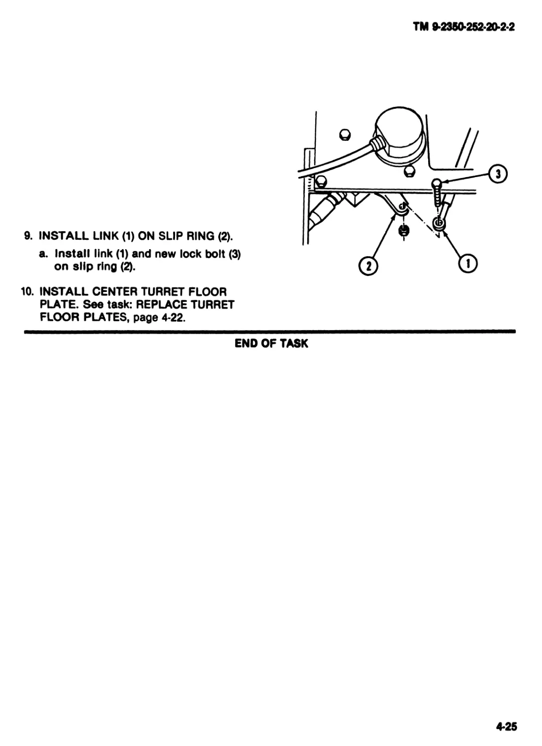
9. INSTALL LINK (1) ON SLIP RING (2).
a. Install link (1) and new lock bolt (3)
on slip ring (2).
10. INSTALL CENTER TURRET FLOOR
PLATE. See task: REPLACE TURRET
FLOOR PLATES, page 4-22.
END OF TASK
4*25
TM 9-2360-252-20-2-2
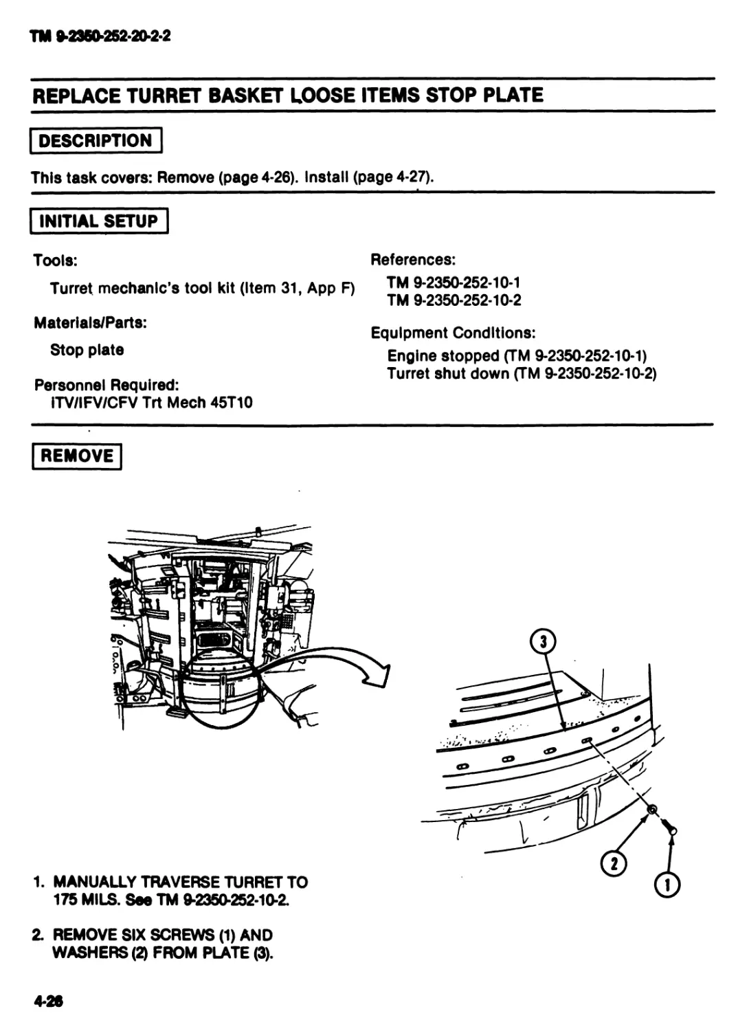
REPLACE TURRET BASKET LOOSE ITEMS STOP PLATE
DESCRIPTION
This task covers: Remove (page 4-26). Install (page 4-27).
INITIAL SETUP
Tools:
Turret mechanic’s tool kit (Item 31, App F)
Materlals/Parts:
Stop plate
Personnel Required:
ITV/IFV/CFV Trt Meeh 45T10
References:
TM 9-2350-252-10-1
TM 9-2350-252-10-2
Equipment Conditions:
Engine stopped (TM 9-2350-252-10-1)
Turret shut down (TM 9-2350-252-10-2)
REMOVE
1. MANUALLY TRAVERSE TURRET TO
175 MILS. See TM 9-2350-252-10-2.
2. REMOVE SIX SCREWS (1) AND
WASHERS (2) FROM PLATE (3).
4-26
TM 92350-252-20-2-2
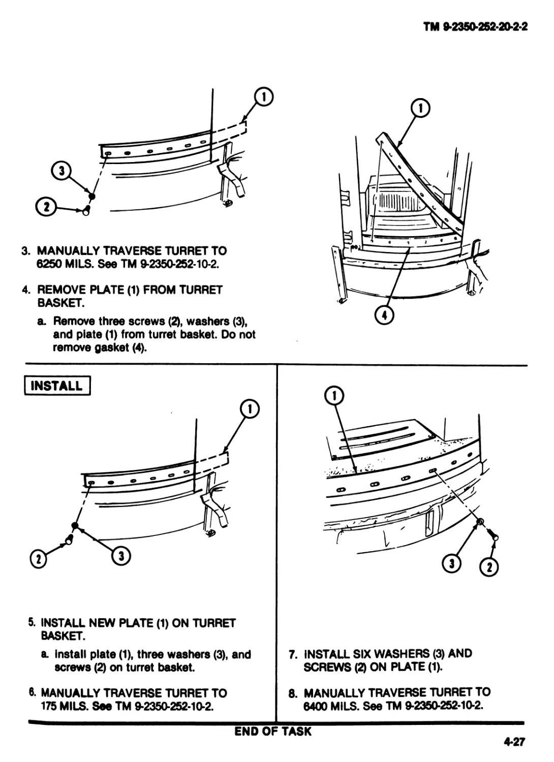
3. MANUALLY TRAVERSE TURRET TO
6250 MILS. See TM 9-2350-252-10-2.
4. REMOVE PLATE (1) FROM TURRET
BASKET.
a. Remove three screws (2), washers (3),
and plate (1) from turret basket. Do not
remove gasket (4).
5. INSTALL NEW PLATE (1) ON TURRET
BASKET.
a Install plate (1), three washers (3), and
screws (2) on turret basket.
6. MANUALLY TRAVERSE TURRET TO
175 MILS. See TM 9*2350-252-10*2.
7. INSTALL SIX WASHERS (3) AND
SCREWS (2) ON PLATE (1).
8. MANUALLY TRAVERSE TURRET TO
6400 MILS. See TM 9-2350-252-10-2.
END OF TASK
4-27
TM 9*2350*252*20*2*2
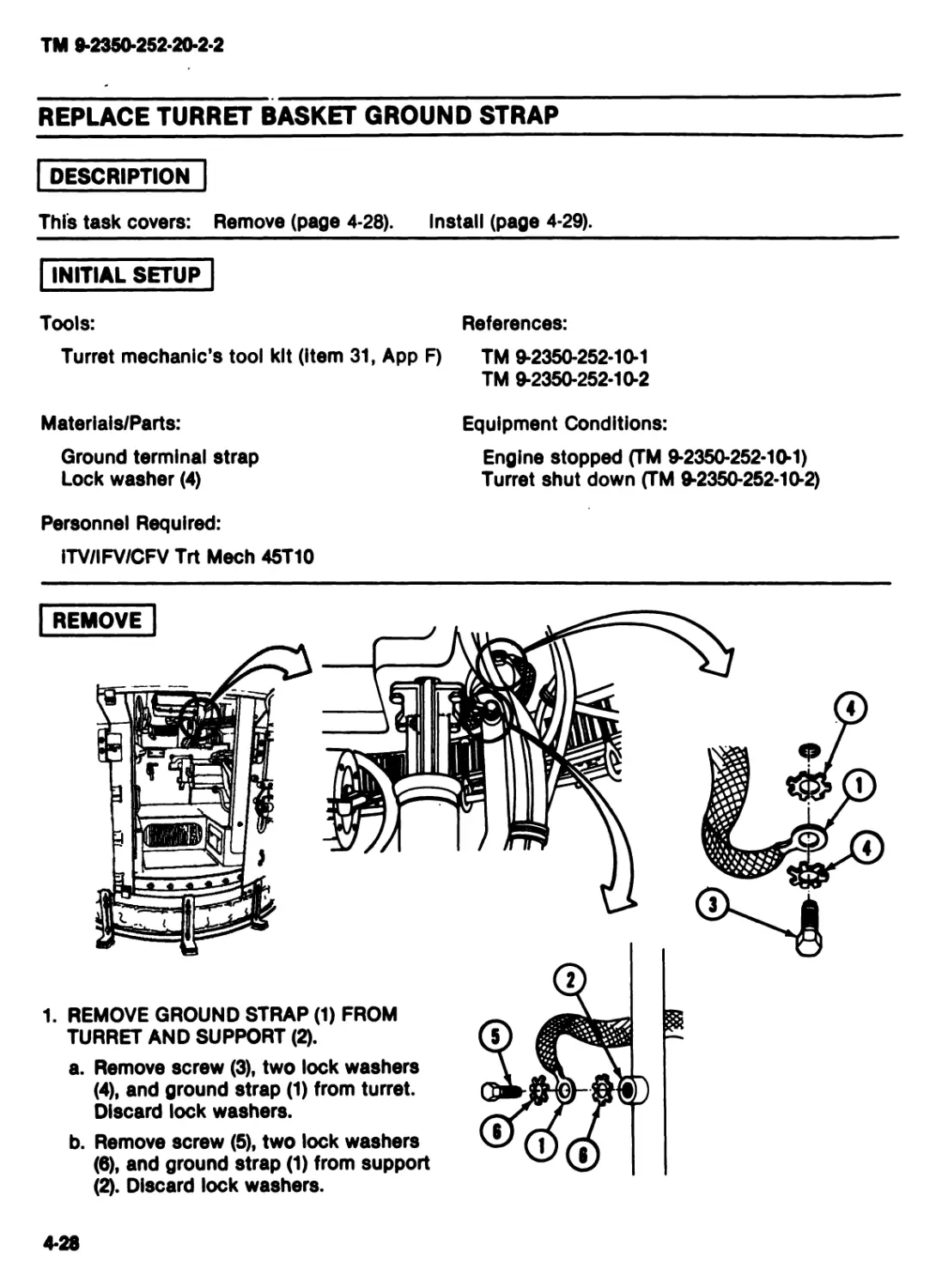
REPLACE TURRET BASKET GROUND STRAP
DESCRIPTION
This task covers: Remove (page 4-28).
INITIAL SETUP"
Tools:
Turret mechanic’s tool kit (Item 31, App
Materlals/Parts:
Ground terminal strap
Lock washer (4)
Personnel Requlred:
ITV/IFV/CFV Trt Meeh 45T10
Install (page 4-29).
References:
TM 9-2350-252-10-1
TM 9-2350-252-10-2
Equipment Conditions:
Engine stopped (TM 9-2350-252-10-1)
Turret shut down (TM 9-2350-252-10-2)
1. REMOVE GROUND STRAP (1) FROM
TURRET AND SUPPORT (2).
a. Remove screw (3), two lock washers
(4), and ground strap (1) from turret.
Discard lock washers.
b. Remove screw (5), two lock washers
(6), and ground strap (1) from support
(2). Discard lock washers.
4-28
TM 9-2350-252-20-2-2
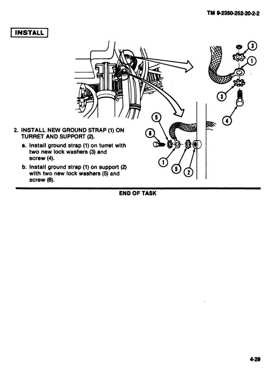
INSTALL
2. INSTALL NEW GROUND STRAP (1) ON
TURRET AND SUPPORT (2).
a. Install ground strap (1) on turret with
two new lock washers (3) and
screw (4).
b. Install ground strap (1) on support (2)
with two new lock washers (5) and
screw (6).
END OF TASK
4-29
TM 9-2350-252-20-2-2
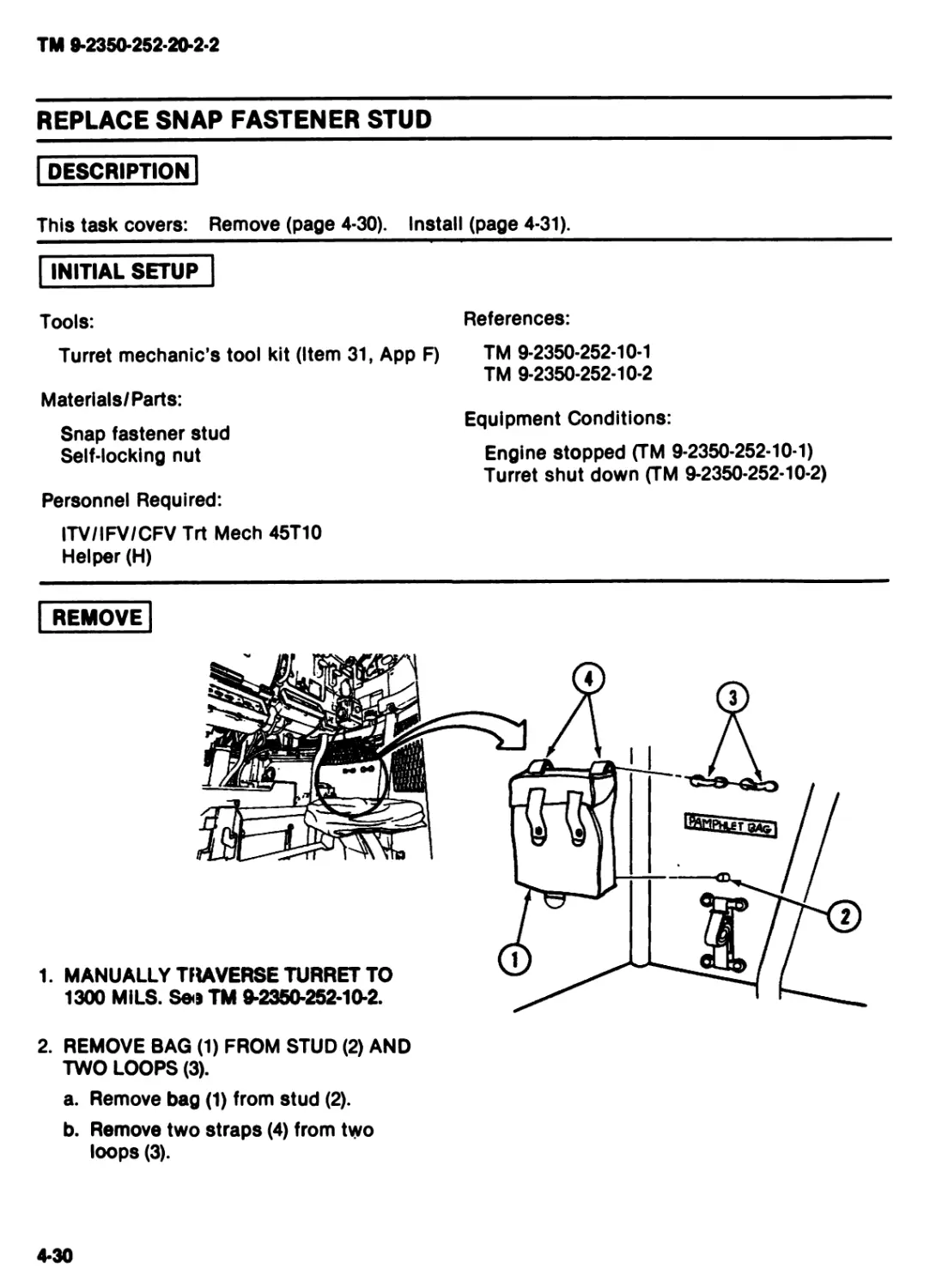
REPLACE SNAP FASTENER STUD
DESCRIPTION
This task covers: Remove (page 4-30). Install (page 4-31).
INITIAL SETUP
Tools:
Turret mechanic’s tool kit (Item 31,
Materials/Parts:
Snap fastener stud
Self-locking nut
Personnel Required:
ITV/IFV/CFV Trt Meeh 45T10
Helper (H)
AppF)
References:
TM 9-2350-252-10-1
TM 9-2350-252-10-2
Equipment Conditions:
Engine stopped (TM 9-2350-252-10-1)
Turret shut down (TM 9-2350-252-10-2)
REMOVE
2. REMOVE BAG (1) FROM STUD (2) AND
TWO LOOPS (3).
a. Remove bag (1) from stud (2).
b. Remove two straps (4) from two
loops (3).
4-30
TM 9-2350-252-20-2-2
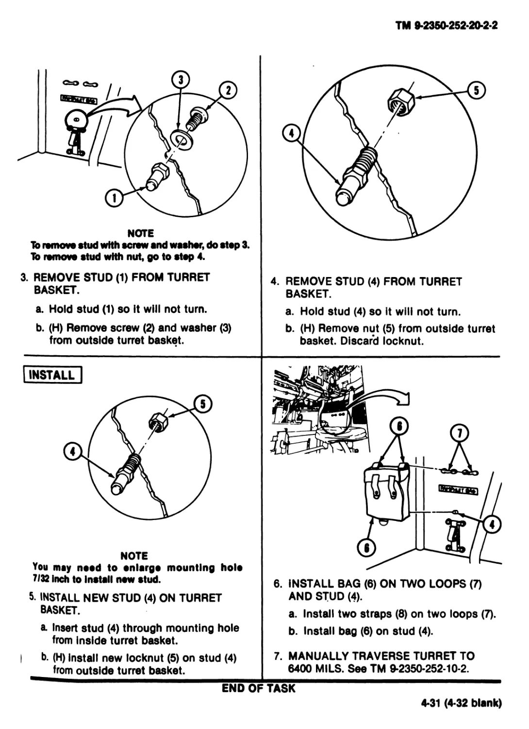
NOTE
To remove stud with screw and washer, do step 3.
lb remove stud with nut, go to step 4.
3. REMOVE STUD (1) FROM TURRET
BASKET.
a. Hold stud (1) so it will not turn.
b. (H) Remove screw (2) and washer (3)
from outside turret basket.
4. REMOVE STUD (4) FROM TURRET
BASKET.
a. Hold stud (4) so it will not turn.
b. (H) Remove nut (5) from outside turret
basket. Discard locknut.
INSTALL
NOTE
You may need to enlarge mounting hole
7/32 inch to Install new stud.
5. INSTALL NEW STUD (4) ON TURRET
BASKET.
a Insert stud (4) through mounting hole
from inside turret basket.
I b. (H) Install new locknut (5) on stud (4)
from outside turret basket.
6. INSTALL BAG (6) ON TWO LOOPS (7)
AND STUD (4).
a. Install two straps (8) on two loops (7).
b. Install bag (6) on stud (4).
7. MANUALLY TRAVERSE TURRET TO
6400 MILS. See TM 9-2350-252-10-2.
END OF TASK
4-31 (4-32 blank)
TM 9-2350-252-20-2-2
Section IV. MAINTENANCE OF SMOKE GRENADE LAUNCHER
Г ASK INDEX
Task Page Task Page
Remove/lnstall Smoke Grenade
Remove/lnstall Smoke Grenade
Launcher
4-34 Bin
4-36
4-33
TM 9-2350-252-20-2-2
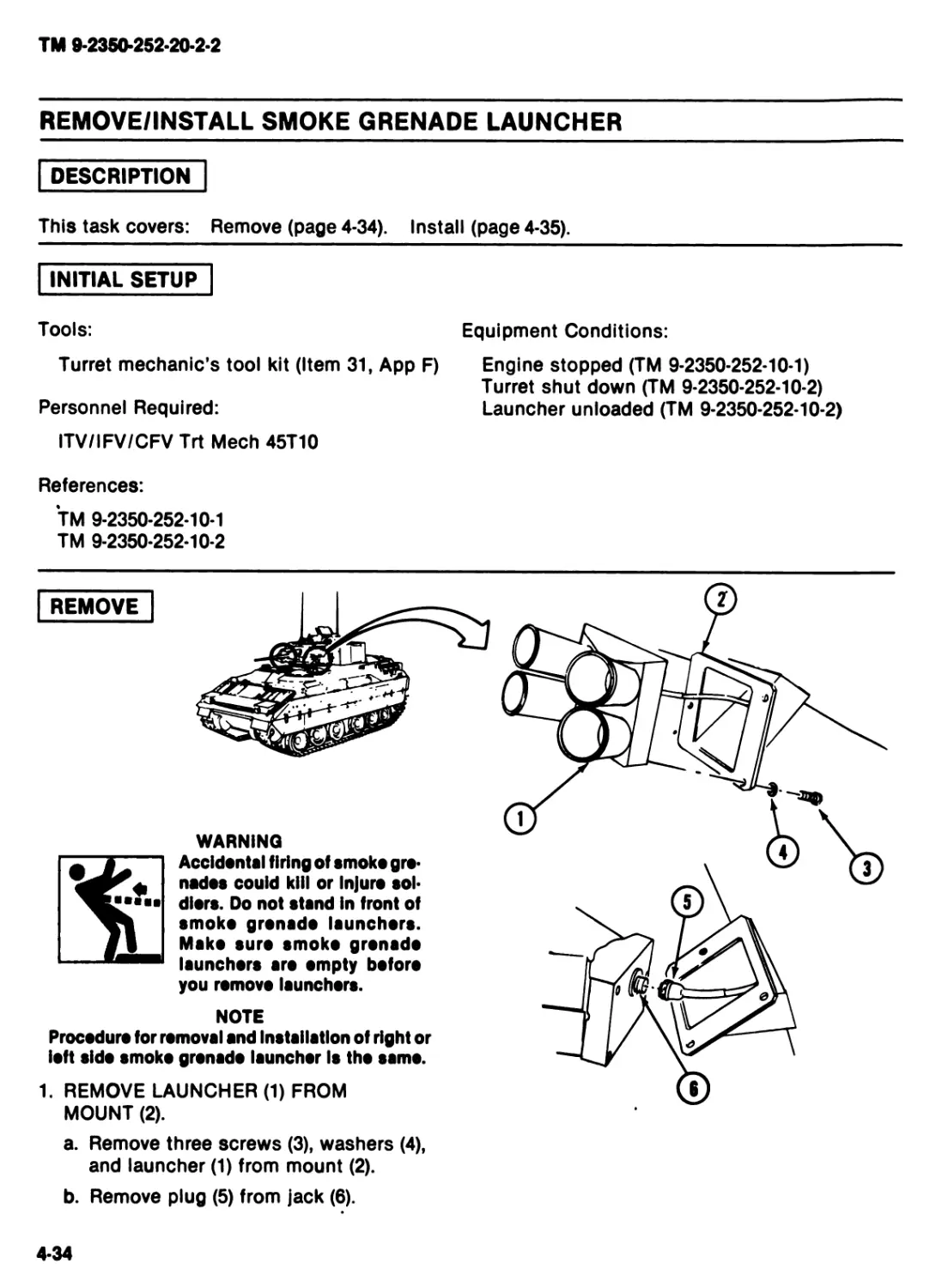
REMOVE/INSTALL SMOKE GRENADE LAUNCHER
DESCRIPTION
This task covers: Remove (page 4-34). Install (page 4-35).
INITIAL SETUP
Tools:
Equipment Conditions:
Turret mechanic’s tool kit (Item 31, App F)
Personnel Required:
ITV/IFV/CFV Trt Meeh 45T10
References:
TM 9-2350-252-10-1
TM 9-2350-252-10-2
Engine stopped (TM 9-2350-252-10-1)
Turret shut down (TM 9-2350-252-10-2)
Launcher unloaded (TM 9-2350-252-10-2)
WARNING
Accidental firing of smoko gre-
nades couid kill or Injure sol-
diers. Do not stsnd In front of
smoko gronsdo Isunchors.
Msko euro smoko gronsdo
Isunchors aro empty boforo
you romovo launchers.
NOTE
Procedure for romovol and Installation of right or
loft sldo smoko gronsdo lounchor Is tho ssmo.
1. REMOVE LAUNCHER (1) FROM
MOUNT (2).
a. Remove three screws (3), washers (4),
and launcher (1) from mount (2).
b. Remove plug (5) from jack (6).
4-34
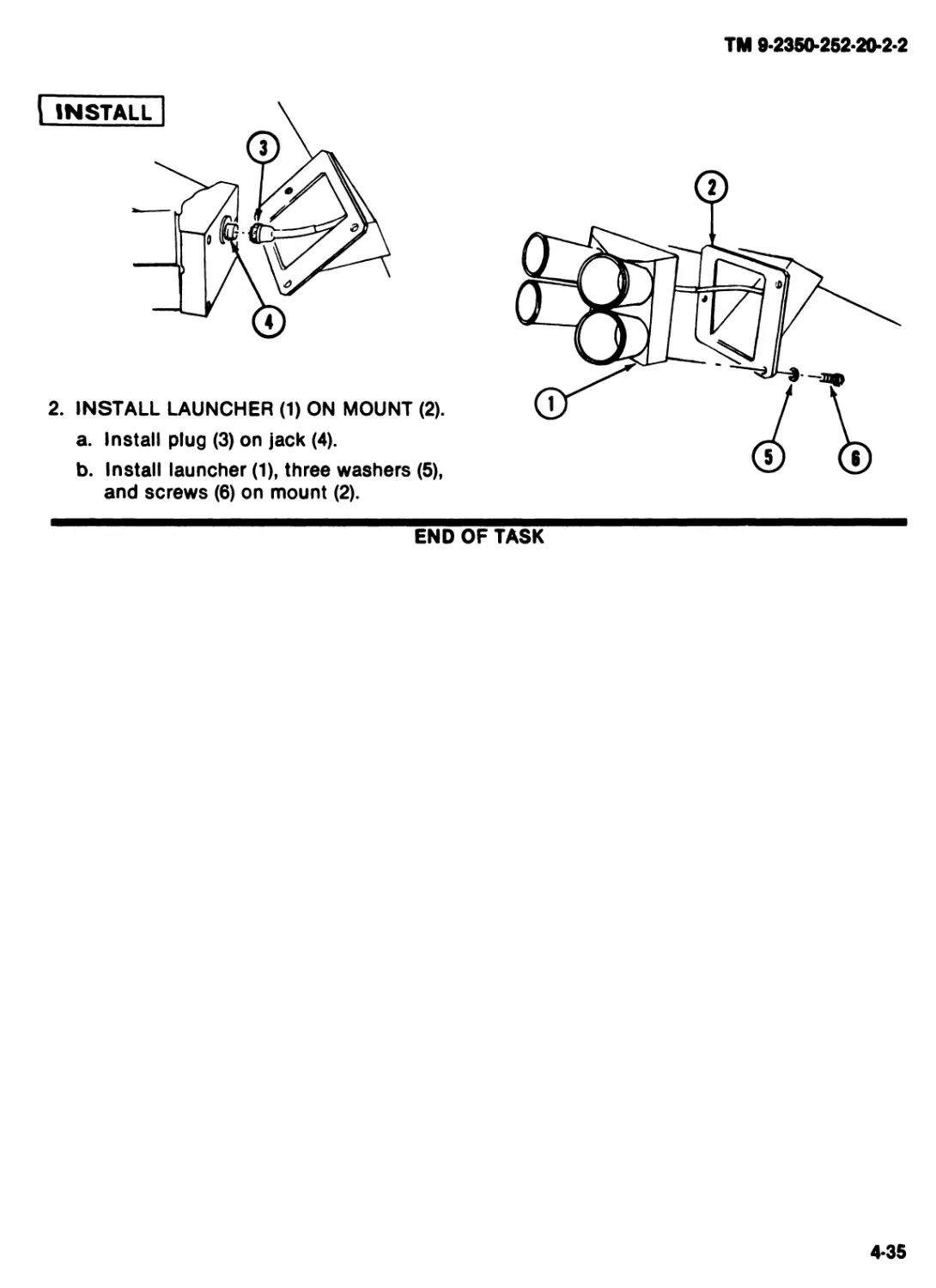
TM 9-235O-252-2O-2-2
2. INSTALL LAUNCHER (1) ON MOUNT (2).
a. Install plug (3) on jack (4).
b. Install launcher (1), three washers (5),
and screws (6) on mount (2).
END OF TASK
4-35
TM 9-2350-262-20-2-2
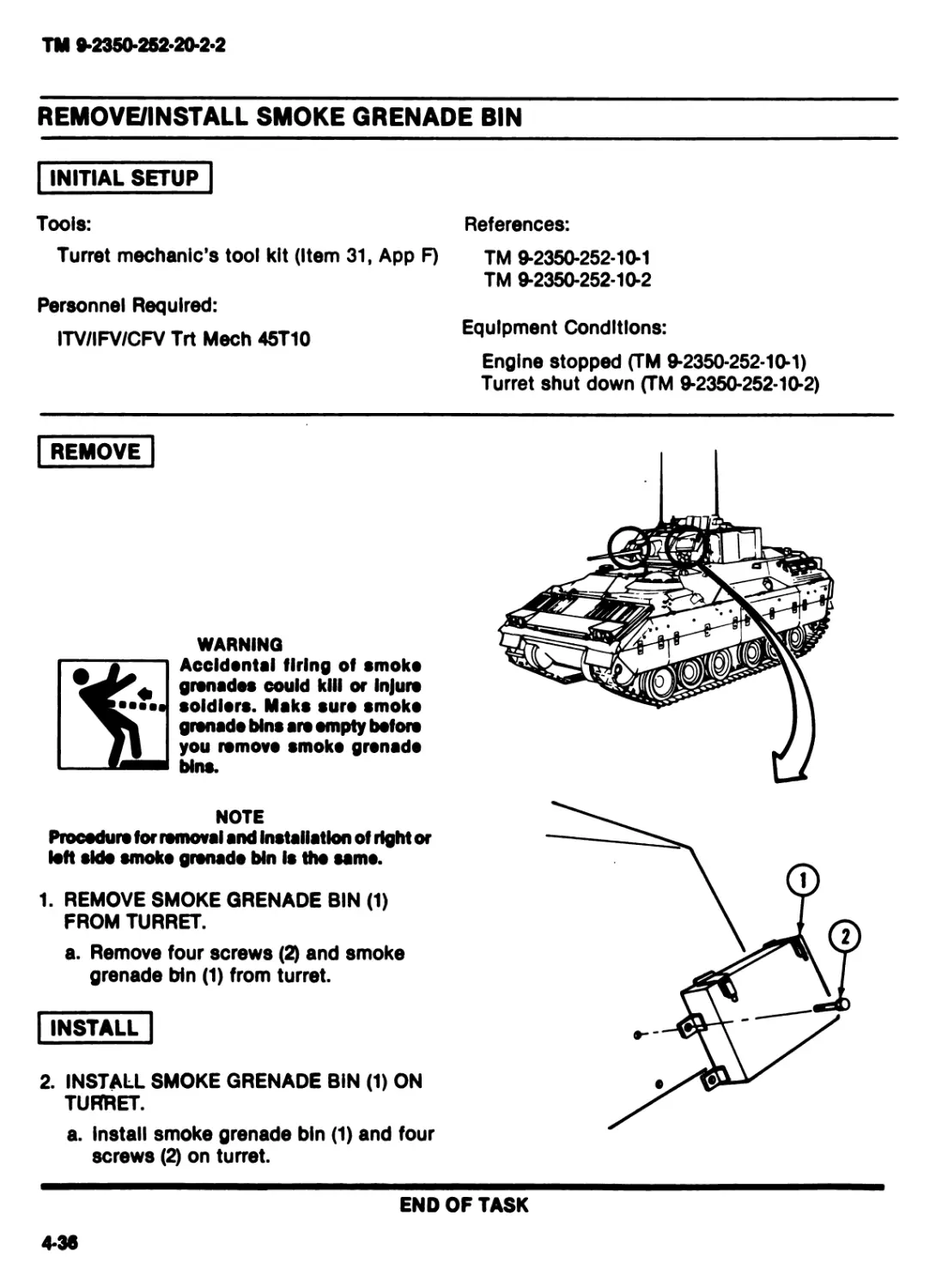
REMOVE/INSTALL SMOKE GRENADE BIN
INITIAL SETUP
Tools:
Turret mechanic’s tool kit (Item 31, App F)
Personnel Required:
ITV/IFV/CFV Trt Meeh 45T10
References:
TM 9*2350-252-10-1
TM 9-2350-252-10-2
Equipment Conditions:
Engine stopped (TM 9-2350-252-10-1)
Turret shut down (TM 9-2350-252-10-2)
REMOVE
WARNING
Accidental firing of smoko
grenades could kill or Injure
soldiers. Maks sure smoko
grenade blns are empty before
you remove smoko grenade
blns.
NOTE
Procedure for removal and Installation of right or
loft aldo smoko grenade Ып Is the samo.
1. REMOVE SMOKE GRENADE BIN (1)
FROM TURRET.
a. Remove four screws (2) and smoke
grenade bin (1) from turret.
INSTALL
2. INSTALL SMOKE GRENADE BIN (1) ON
TURRET.
a. install smoke grenade bin (1) and four
screws (2) on turret.
END OF TASK
4-36
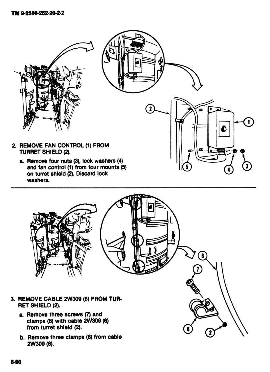
TM 9-2350-252-20-2-2
Section V. MAINTENANCE OF COMMUNICATIONS EQUIPMENT
TASK INDEX
Task Page
Remove/lnstall Radios............4-38
Remove/lnstall Radio Antenna
Cables...........................4-42
Remove/lnstall Radio Mountings ..... 4-45
Task Page
Remove/lnstall Cable Assembly
CX-4723/VRC (3 FT)...................4-50
Remove/lnstall Cable Assembly
CX-4723/VRC (5 FT)...................4-53
4-37
TM 9-2350-252*20-2*2
REMOVE/INSTALL RADIOS
DESCRIPTION
This task covers: Remove (page 4-38). Install (page 4-40).
INITIAL SETUP
Personnel Required:
ITV/IFV/CFV Trt Meeh 45T10
Helper (H)
References:
TM 9-2350-252-10-1
TM 9-2350-252-10-2
Equipment Conditions:
Engine stopped (TM 9-2350-252-10-1)
Turret shut down (TM 9-2350-252-10-2)
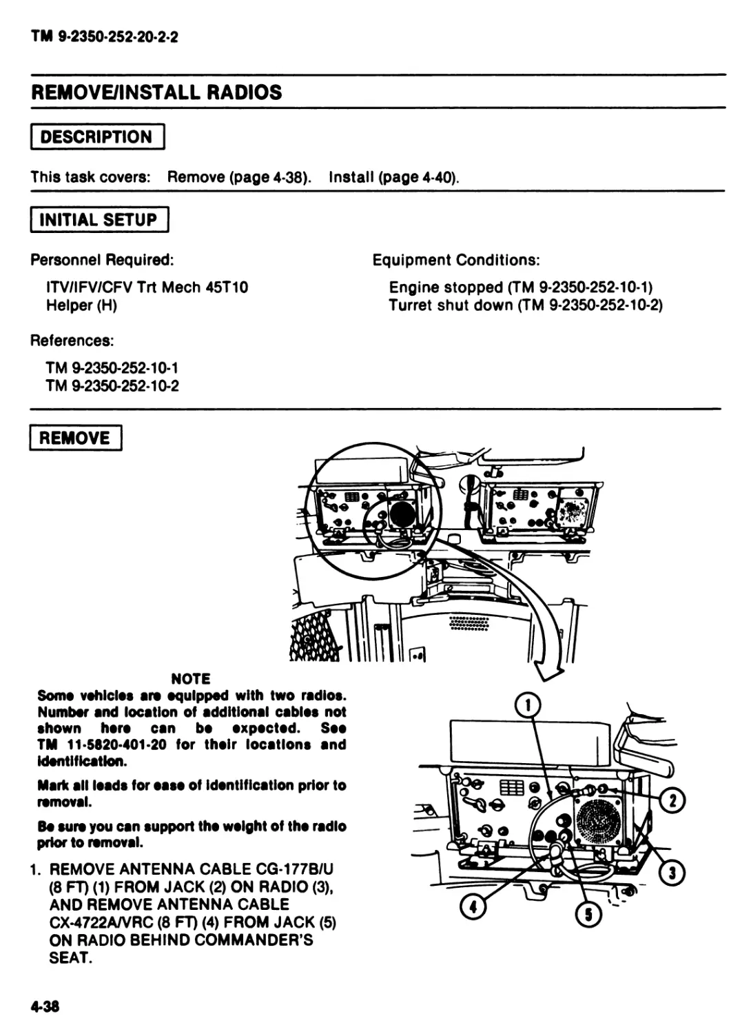
REMOVE
NOTE
Some vehicles are equipped with two radios.
Number and location of additional cables not
shown horo can bo expected. See
TM 11-5820-401-20 for their locations and
Identification.
Mark all loads for oaso of identification prior to
removal.
Bo sure you can support tho weight of tho radio
prior to removal.
1. REMOVE ANTENNA CABLE CG-177B/U
(8 FT) (1) FROM JACK (2) ON RADIO (3).
AND REMOVE ANTENNA CABLE
CX-4722A/VRC (8 FT) (4) FROM JACK (5)
ON RADIO BEHIND COMMANDER'S
SEAT.
4-38
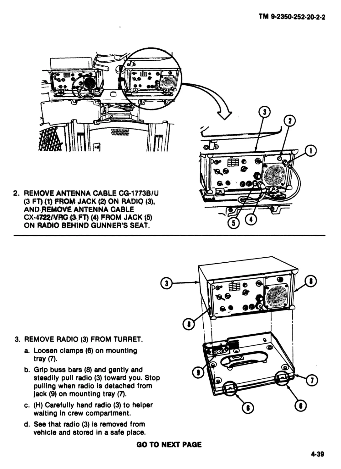
TM 9*2350*252*20*2*2
2. REMOVE ANTENNA CABLE CG-1773В/U
(3 FT) (1) FROM JACK (2) ON RADIO (3),
ANDREMOVE ANTENNA CABLE
СХ-4722/VRC (3 FT) (4) FROM JACK (5)
ON RADIO BEHIND GUNNER'S SEAT.
3. REMOVE RADIO (3) FROM TURRET.
a. Loosen clamps (0) on mounting
tray (7).
b. Grip buss bars (8) and gently and
steadily pull radio (3) toward you. Stop
pulling when radio is detached from
jack (9) on mounting tray (7).
с. (H) Carefully hand radio (3) to helper
waiting in crew compartment.
d. See that radio (3) is removed from
vehicle and stored in a safe place.
GO TO NEXT PAGE
4*39
TM 9*2350-252*20*2*2
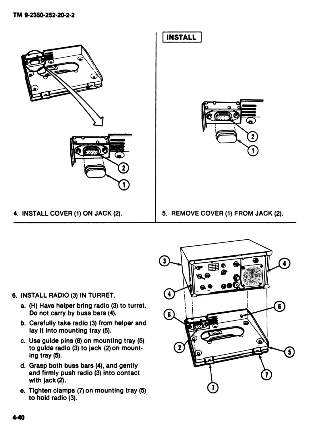
INSTALL
4. INSTALL COVER (1) ON JACK (2).
5. REMOVE COVER (1) FROM JACK (2).
6. INSTALL RADIO (3) IN TURRET.
a. (H) Have helper bring radio (3) to turret.
Do not carry by buss bars (4).
b. Carefully take radio (3) from helper and
lay it into mounting tray (5).
c. Use guide pins (5) on mounting tray (5)
to guide radio (3) to jack (2) on mount-
ing tray (5).
d. Grasp both buss bars (4), and gently
and firmly push radio (3) into contact
with jack (2)*
e. Tighten clamps (7) on mounting tray (5)
to hold radio (3).
4-40
TM 9-2350*252*20*2-2
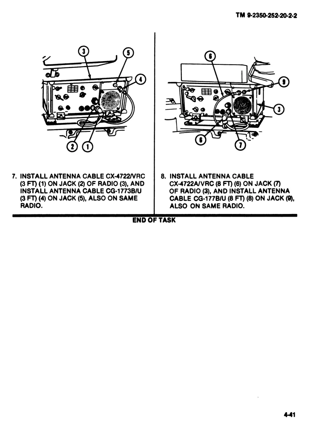
7. INSTALL ANTENNA CABLE CX-4722/VRC
(3 FT) (1) ON JACK (2) OF RADIO (3), AND
INSTALL ANTENNA CABLE CG-1773B/U
(3 FT) (4) ON JACK (5). ALSO ON SAME
RADIO.
8. INSTALL ANTENNA CABLE
CX-4722A/VRC (8 FT) (6) ON JACK (7)
OF RADIO (3). AND INSTALL ANTENNA
CABLE CG-177B/U (8 FT) (8) ON JACK (9),
ALSO ON SAME RADIO.
END OF TASK
4-41
TM 9-2350-252-20-2-2
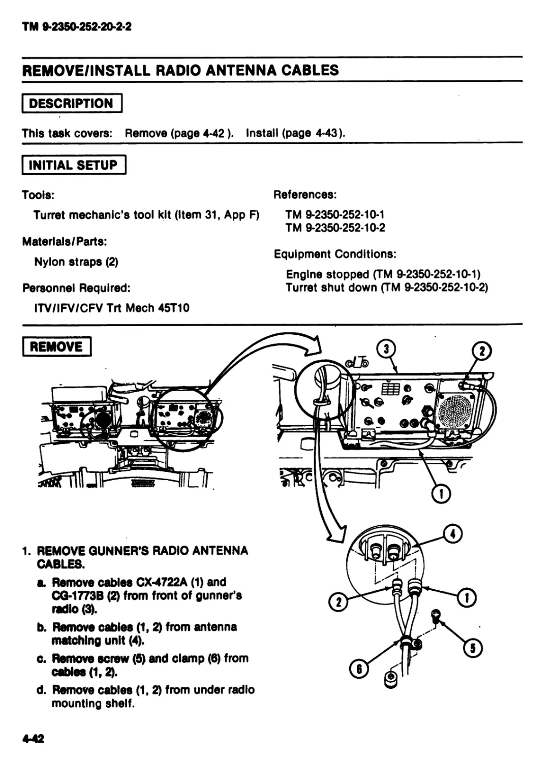
REMOVE/INSTALL RADIO ANTENNA CABLES
DESCRIPTION
This task covers: Remove (page 4*42). Install (page 4-43).
INITIAL SETUP
Tools: References:
Turret mechanic’s tool kit (Item 31, App F) TM 9-2350-252-10-1
TM 9-2350-252-10-2
Materials/Parts:
.. . . ... Equipment Conditions:
Nylon straps (2) M
Engine stopped (TM 9-2350-252-10-1)
Personnel Required: Turret shut down (TM 9-2350-252-10-2)
ITV/IFV/CFV Trt Meeh 45T10
mounting shelf.
4*42
TM 9-2350-252-20-2-2
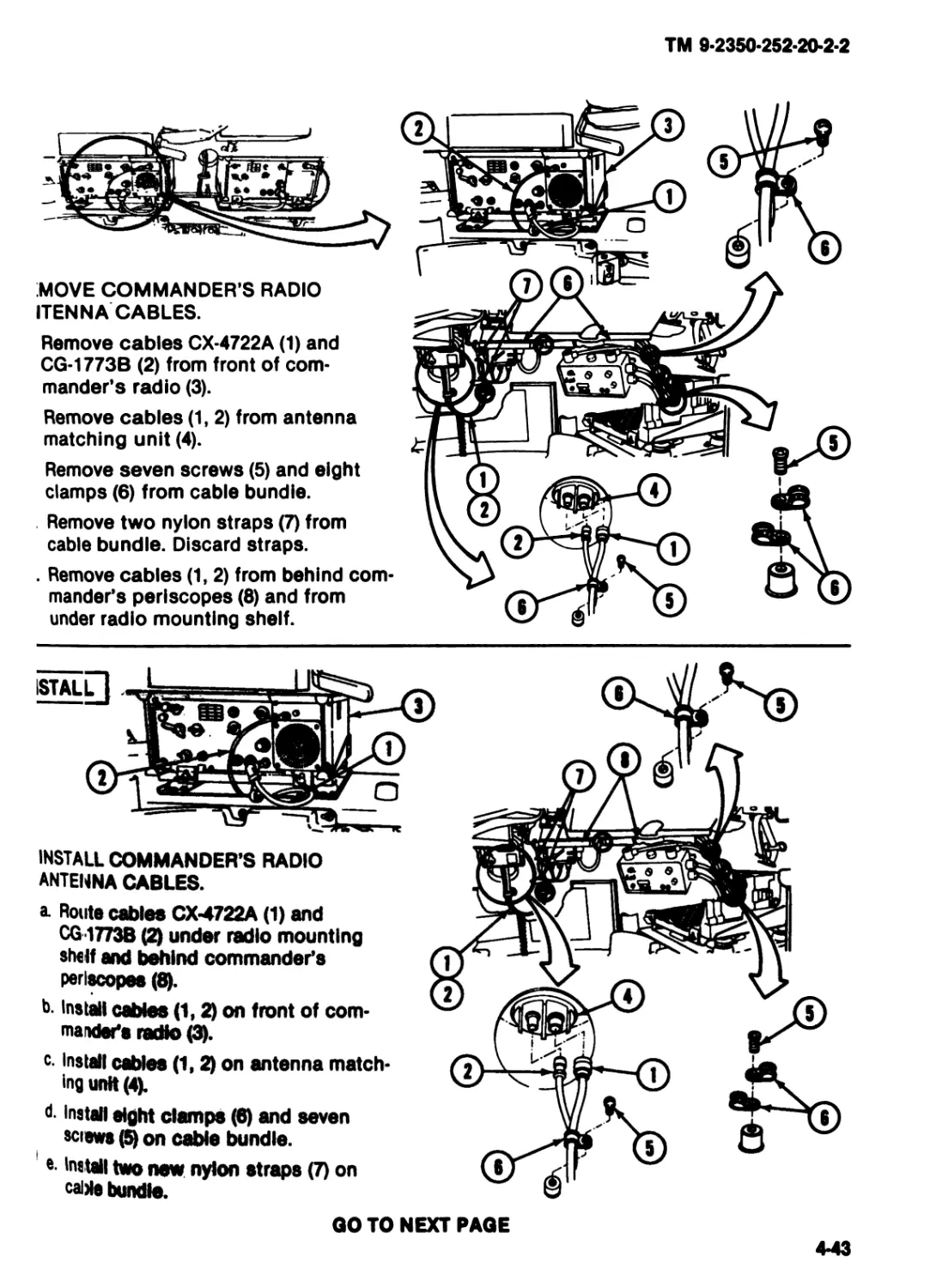
MOVE COMMANDER'S RADIO
ITENNA CABLES.
Remove cables CX-4722A (1) and
CG-1773B (2) from front of com-
mander's radio (3).
Remove cables (1, 2) from antenna
matching unit (4).
Remove seven screws (5) and eight
clamps (6) from cable bundle.
Remove two nylon straps (7) from
cable bundle. Discard straps.
. Remove cables (1,2) from behind com-
mander's periscopes (8) and from
under radio mounting shelf.
istall]
INSTALL COMMANDER'S RADIO
ANTENNA CABLES.
a. Route cables CX4722A (1) and
CG-1773B under radio mounting
shelf and behind commander's
periscopes (8).
b Install cables (1,2) on front of com-
mander's radio (3).
c. install cables (1,2) on antenna match-
ing unit (4).
d- install eight clamps (6) and seven
sciews (5) on cable bundle.
*• install two new nylon straps (7) on
calMe bundle.
GO TO NEXT PAGE
4-43
TM 9*2350*252*20*2*2
a.
b.
c.
d.
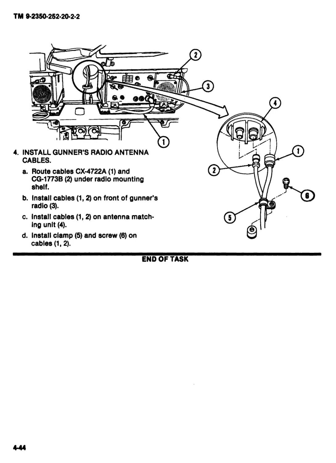
4. INSTALL GUNNER’S RADIO ANTENNA
CABLES.
Route cables CX-4722A (1) and
CG*1773B (2) under radio mounting
shelf.
Install cables (1,2) on front of gunner’s
radio (3).
Install cables (1,2) on antenna match*
Ing unit (4).
Install clamp (5) and screw (6) on
cables (1,2).
END OF TASK
4*44
TM 9-2350-252-20-2-2
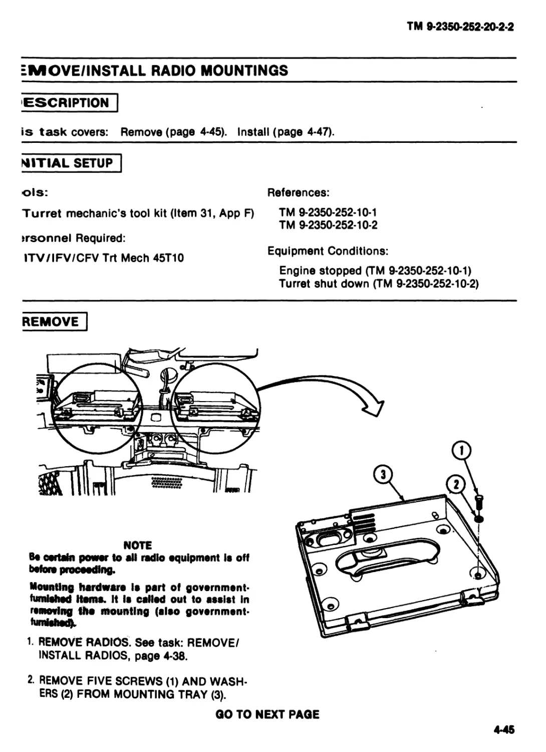
EMOVE/INSTALL RADIO MOUNTINGS
ESCRIPTION
is task covers: Remove (page 4-45). Install (page 4-47).
MITTAL SETUP
ols: References:
Turret mechanic’s tool kit (Item 31, App F) TM 9-2350-252-10-1
TM 9-2350-252-10-2
trsonnel Required:
ITV/IFV/CFV Trt Meeh 45T10 Equipment Conditions:
Engine stopped (TM 9-2350-252-10-1)
Turret shut down (TM 9-2350-252-10-2)
REMOVE
NOTE
Be certain power to all radio equipment is off
before proceeding.
Mounting hardware Is part of government-
furnished Homs. It is called out to assist In
removing tho mounting (also governmsnt-
♦umishodL
1. REMOVE RADIOS. See task: REMOVE/
INSTALL RADIOS, page 4-38.
2. REMOVE FIVE SCREWS (1) AND WASH-
ERS (2) FROM MOUNTING TRAY (3).
QO TO NEXT PAGE
4-45
TM 9-2350-252-20-2-2
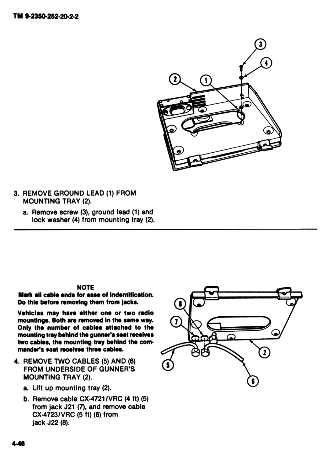
3. REMOVE GROUND LEAD (1) FROM
MOUNTING TRAY (2).
a. Remove screw (3), ground lead (1) and
lock washer (4) from mounting tray (2).
NOTE
Mark all cable ends for oaso of Indontlflcation.
Do this before removing them from jacks.
Vehicles may have olthor ono or two radio
mountings. Both are removed In the same way.
Only tho number of cables attached to the
mounting tray behind the gunner’s seat receives
two cables, tho mounting tray behind the com*
mender's seat receives three cables.
4. REMOVE TWO CABLES (5) AND (6)
FROM UNDERSIDE OF GUNNER’S
MOUNTING TRAY (2).
a. Lift up mounting tray (2).
b. Remove cable CX-4721/VRC (4 ft) (5)
from jack J21 (7), and remove cable
CX-4723/VRC (5 ft) (6) from
jack J22 (8).
4-46
TM 9-2350-252-20-2-2
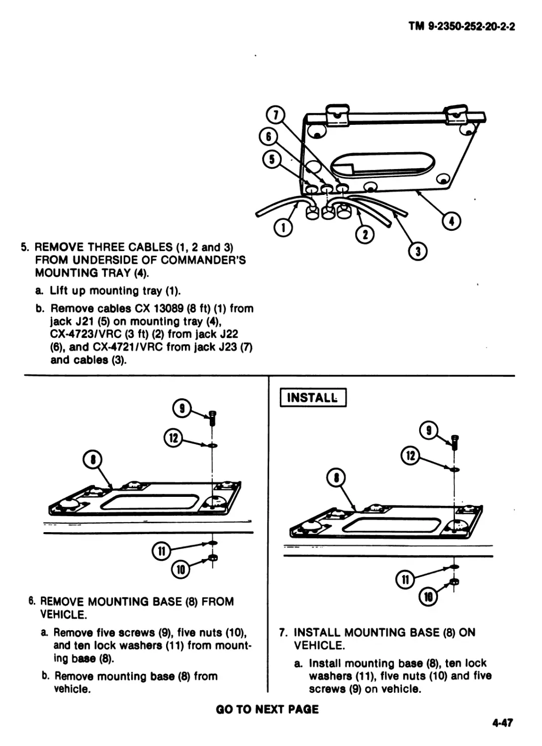
5. REMOVE THREE CABLES (1, 2 and 3)
FROM UNDERSIDE OF COMMANDER’S
MOUNTING TRAY (4).
a. Lift up mounting tray (1).
b. Remove cables CX 13089 (8 ft) (1) from
jack J21 (5) on mounting tray (4),
CX-4723/VRC (3 ft) (2) from jack J22
(6), and CX-4721/VRC from jack J23 (7)
and cables (3).
6. REMOVE MOUNTING BASE (8) FROM
VEHICLE.
INSTALL
a Remove five screws (9), five nuts (10),
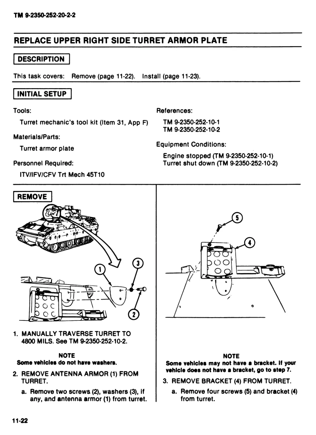
and ten lock washers (11) from mount-
ing base (8).
b. Remove mounting base (8) from
vehicle.
7. INSTALL MOUNTING BASE (8) ON
VEHICLE.
a. Install mounting base (8), ten lock
washers (11), five nuts (10) and five
screws (9) on vehicle.
GO TO NEXT PAGE
4-47
TM 9-2350-252-20-2-2
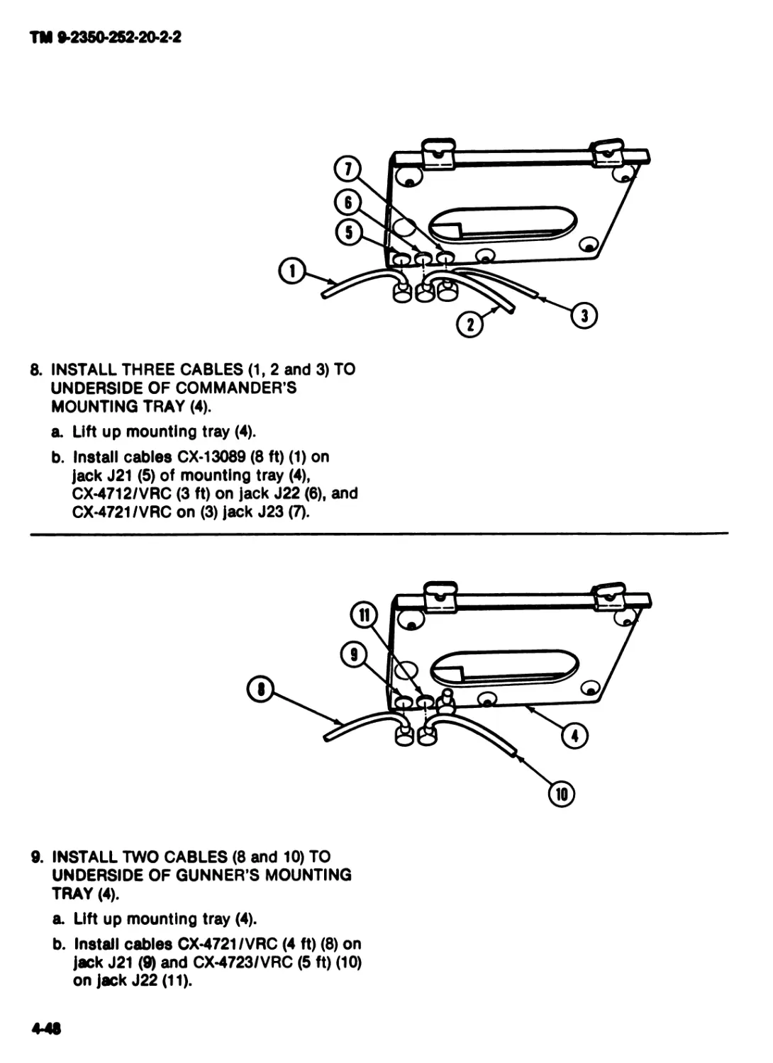
8. INSTALL THREE CABLES (1, 2 and 3) TO
UNDERSIDE OF COMMANDER’S
MOUNTING TRAY (4).
a. Lift up mounting tray (4).
b. Install cables CX-13089 (8 ft) (1) on
jack J21 (5) of mounting tray (4).
CX-4712/VRC (3 ft) on jack J22 (6). and
CX-4721/VRC on (3) jack J23 (7).
9. INSTALL TWO CABLES (8 and 10) TO
UNDERSIDE OF GUNNER’S MOUNTING
TRAY (4).
a. Lift up mounting tray (4).
b. Install cables CX-4721/VRC (4 ft) (8) on
jack J21 (9) and CX-4723/VRC (5 ft) (10)
on jack J22 (11).
4-48
TM 9-2350-252-20-2-2
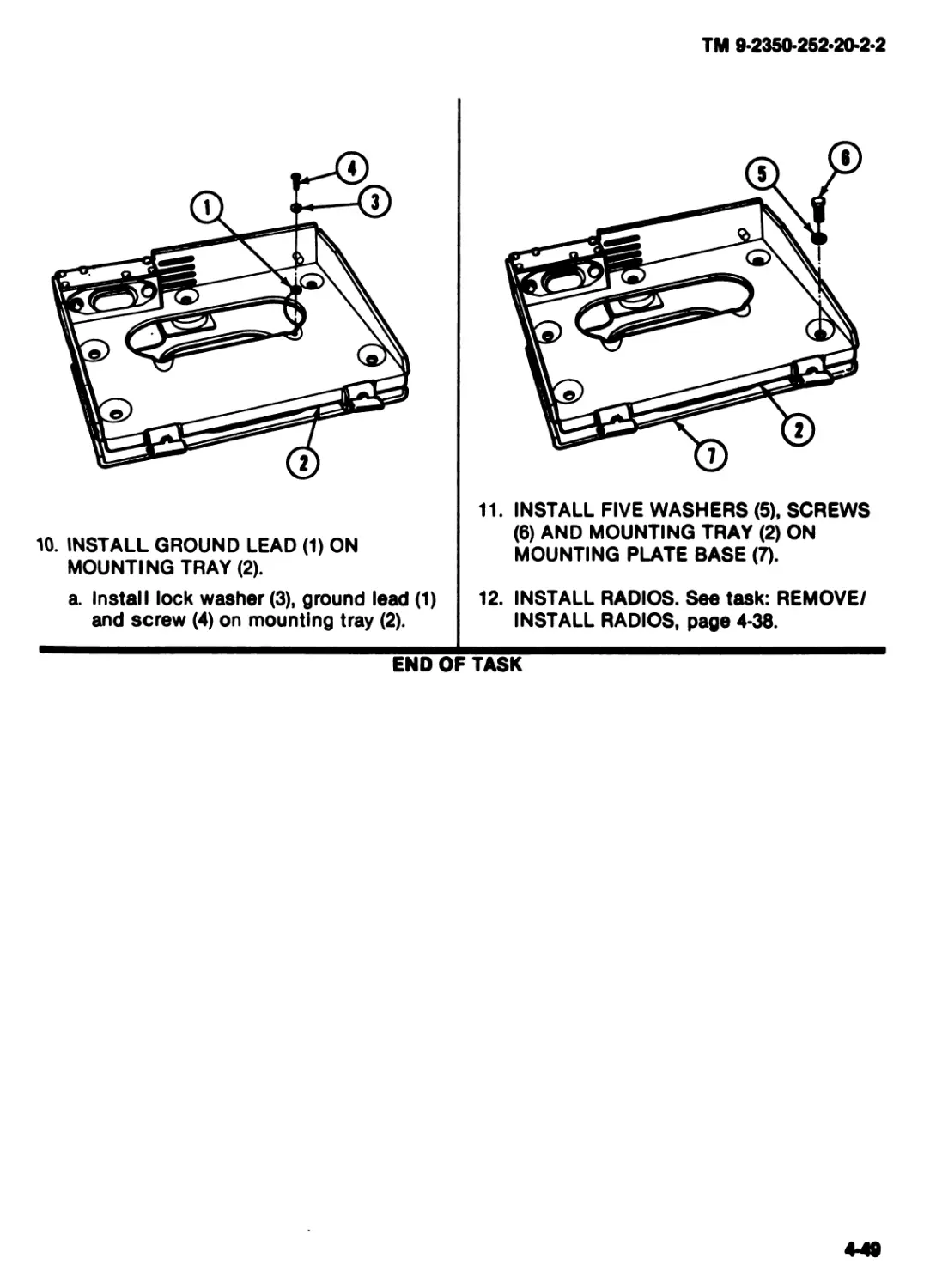
10. INSTALL GROUND LEAD (1) ON
MOUNTING TRAY (2).
a. Install lock washer (3), ground lead (1)
and screw (4) on mounting tray (2).
11. INSTALL FIVE WASHERS (5), SCREWS
(6) AND MOUNTING TRAY (2) ON
MOUNTING PLATE BASE (7).
12. INSTALL RADIOS. See task: REMOVE/
INSTALL RADIOS, page 4-38.
END OF TASK
4-49
TM 9-2350-252-20-2-2
REMOVE/INSTALL CABLE ASSEMBLY CX*4723/VRC (3 FT)
DESCRIPTION
This task covers: Remove (page 4-50). Install (page 4-51).
INITIAL SETUP
Tools: References:
Turret mechanic’s tool kit (Item 31, App F) TM 9-2350-252-10-1
TM 9-2350-252-10-2
Personnel Required:
ITV/IFV/CFV Trt Meeh 45T10 Equipment Conditions:
Engine stopped (TM 9-2350-252-10-1)
Turret shut down (TM 9-2350-252-10-2)
REMOVE
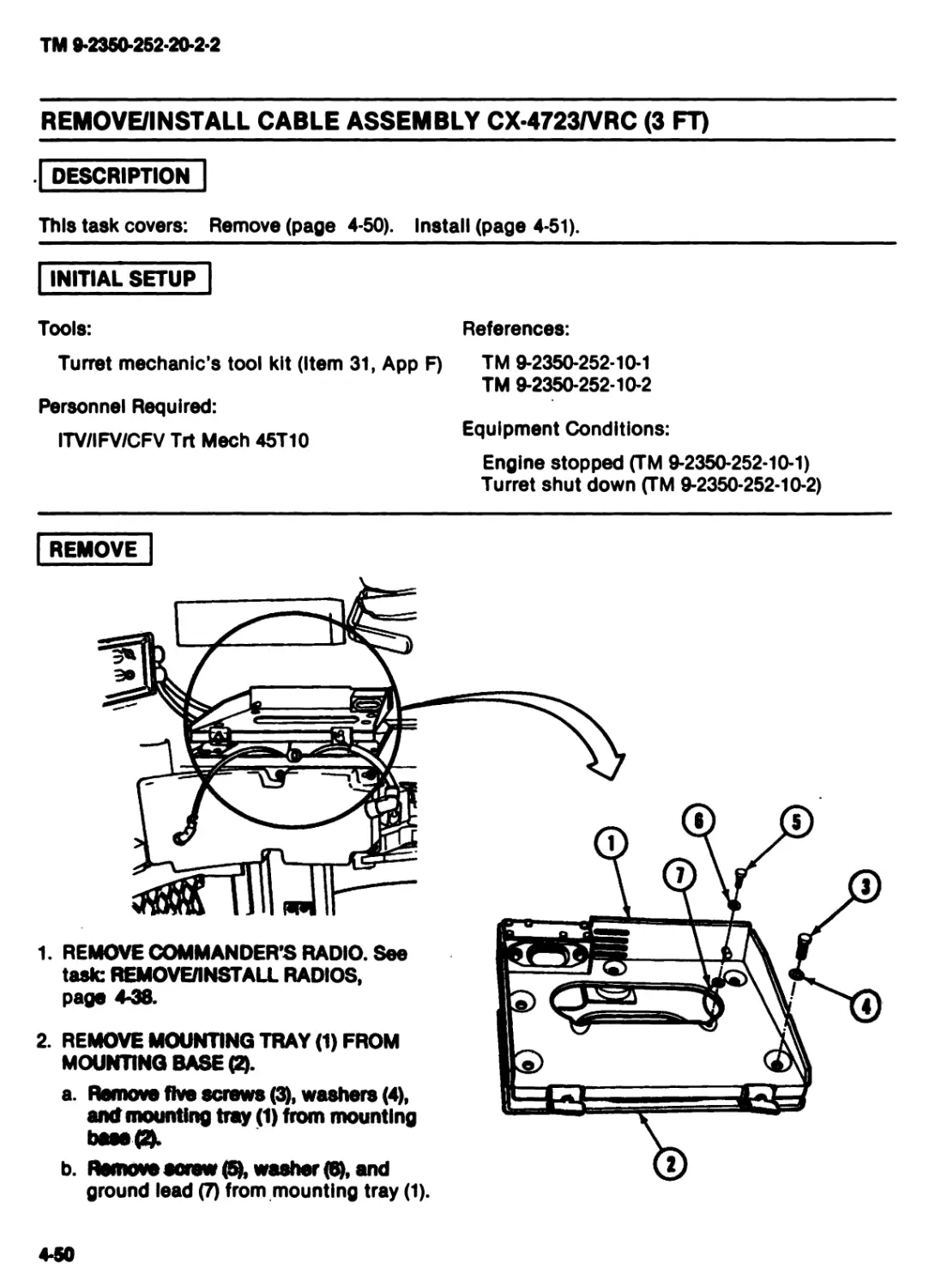
ground lead (7) from mounting tray (1).
1. REMOVE COMMANDER’S RADIO. See
task: REMOVE/INSTALL RADIOS,
page 4-38.
2. REMOVE MOUNTING TRAY (1) FROM
MOUNTING BASE ft.
a. Remove five screws (3), washers (4),
and mounting tray (1) from mounting
base ft
4-50
TM 9*2350*252*20*2*2
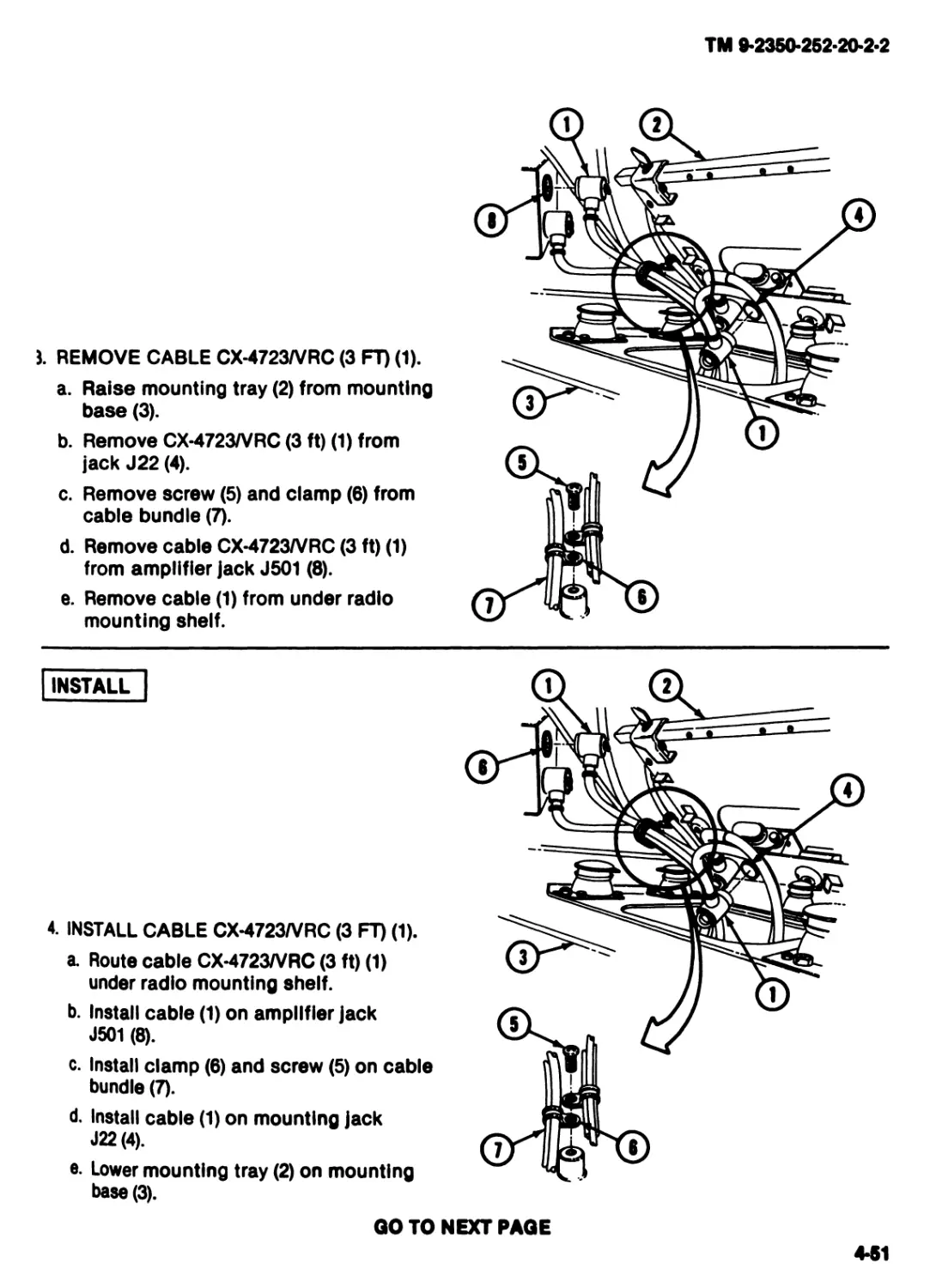
J. REMOVE CABLE CX-4723/VRC (3 FT) (1).
a. Raise mounting tray (2) from mounting
base (3).
b. Remove CX-4723/VRC (3 ft) (1) from
jack J22 (4).
c. Remove screw (5) and clamp (6) from
cable bundle (7).
d. Remove cable CX-4723/VRC (3 ft) (1)
from amplifier jack J501 (8).
e. Remove cable (1) from under radio
mounting shelf.
INSTALL
4. INSTALL CABLE CX-4723/VRC (3 FT) (1).
a. Route cable CX-4723/VRC (3 ft) (1)
under radio mounting shelf.
b. Install cable (1) on amplifier jack
J501 (8).
c. Install clamp (6) and screw (5) on cable
bundle (7).
d. Install cable (1) on mounting jack
J22(4).
e. Lower mounting tray (2) on mounting
base (3).
GO TO NEXT PAGE
4*51
TM 9*2350*252*20-2*2
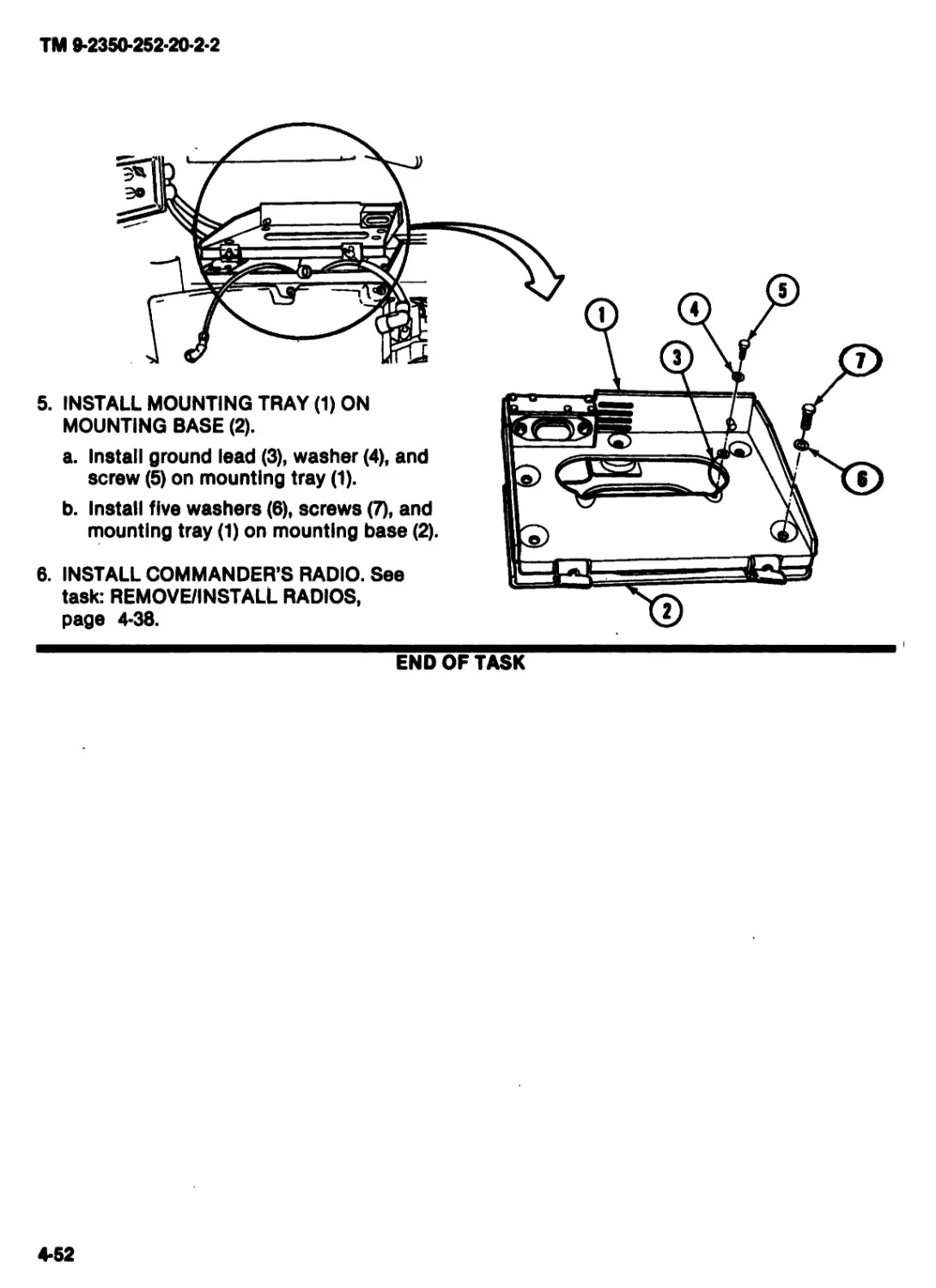
5. INSTALL MOUNTING TRAY (1) ON
MOUNTING BASE (2).
a. Install ground lead (3), washer (4), and
screw (5) on mounting tray (1).
b. Install five washers (6), screws (7), and
mounting tray (1) on mounting base (2).
END OF TASK
6. INSTALL COMMANDER’S RADIO. See
task: REMOVE/INSTALL RADIOS,
page 4-38.
4-52
TM 9*2350-252*20-2-2
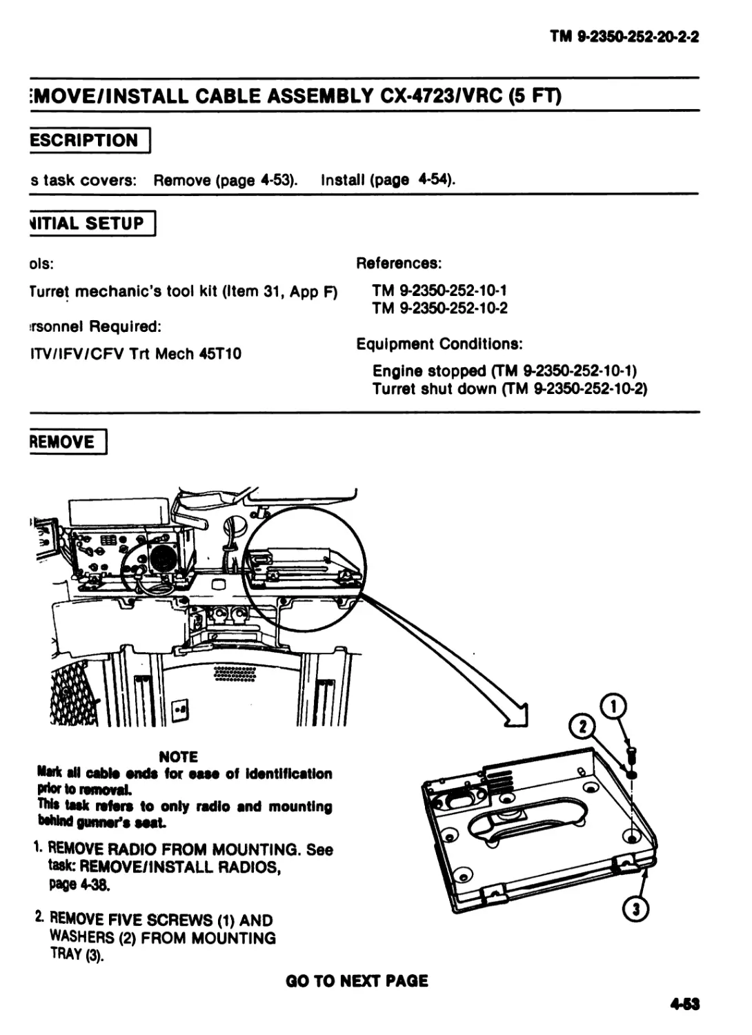
MOVE/INSTALL CABLE ASSEMBLY CX-4723/VRC (5 FT)
ESCRIPTION
s task covers: Remove (page 4-53). Install (page 4-54).
1ITIAL SETUP
ols: References:
Turret mechanic's tool kit (Item 31, App F) TM 9-2350-252-10-1
TM 9-2350-252-10-2
irsonnel Required:
ITV/IFV/CFV Trt Meeh 45T10 Equipment Conditions:
Engine stopped (TM 9-2350-252-10-1)
Turret shut down (TM 9-2350-252-10-2)
REMOVE
WASHERS (2) FROM MOUNTING
TRAY (3).
GO TO NEXT PAGE
4-53
TM 9*2350*252-20-2-2
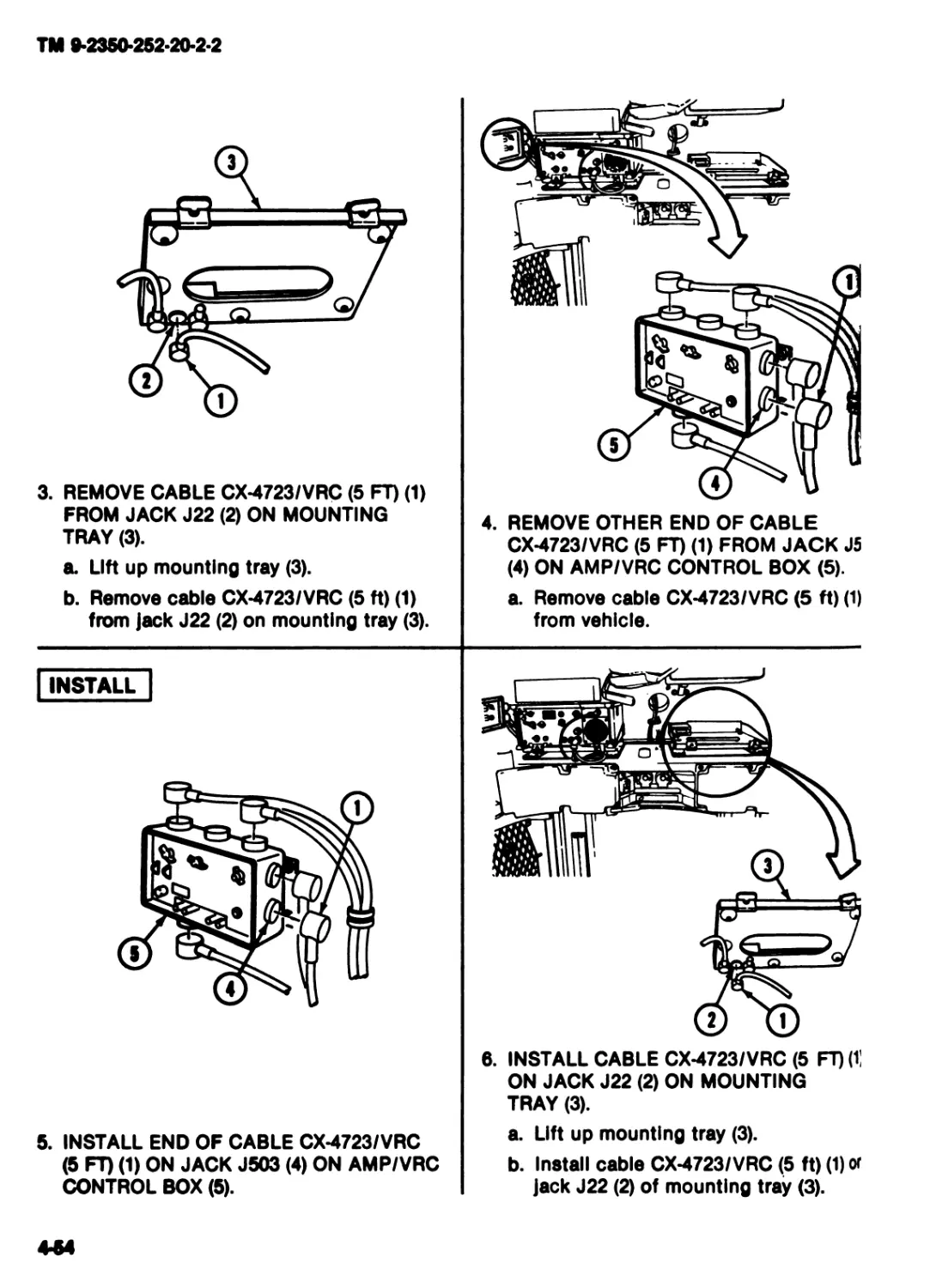
3. REMOVE CABLE CX-4723/VRC (5 FT) (1)
FROM JACK J22 (2) ON MOUNTING
TRAY (3).
a. Lift up mounting tray (3).
b. Remove cable CX-4723/VRC (5 ft) (1)
from jack J22 (2) on mounting tray (3).
4. REMOVE OTHER END OF CABLE
CX-4723/VRC (5 FT) (1) FROM JACK J5
(4) ON AMP/VRC CONTROL BOX (5).
a. Remove cable CX-4723/VRC (5 ft) (1)
from vehicle.
INSTALL
5. INSTALL END OF CABLE CX-4723/VRC
(5 FT) (1) ON JACK J503 (4) ON AMP/VRC
CONTROL BOX (5).
6. INSTALL CABLE CX-4723/VRC (5 FT) (1]
ON JACK J22 (2) ON MOUNTING
TRAY (3).
a. Lift up mounting tray (3).
b. Install cable CX-4723/VRC (5 ft) (1) or
jack J22 (2) of mounting tray (3).
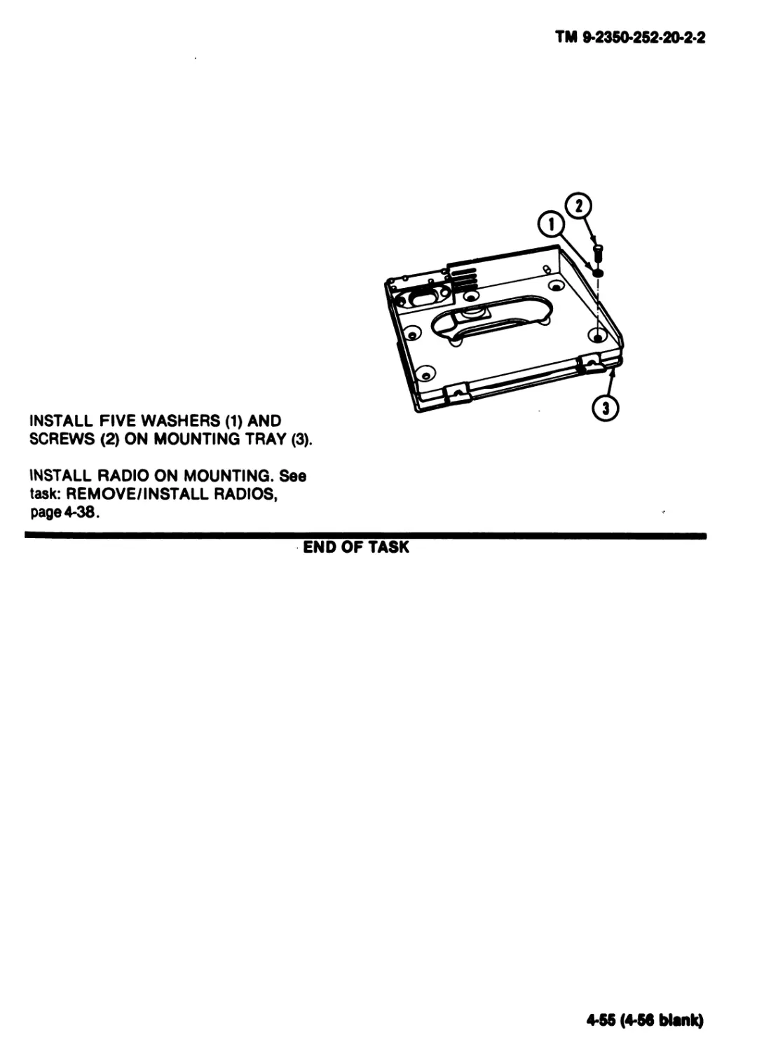
TM 9-2350-252-20-2-2
INSTALL FIVE WASHERS (1) AND
SCREWS (2) ON MOUNTING TRAY (3).
INSTALL RADIO ON MOUNTING. See
task: REMOVE/INSTALL RADIOS,
page 4-38.
END OF TASK
4-55 (4-56 blank)
TM 9*2350-252-20*2*2
Section VI. MAINTENANCE OF TURRET STOWAGE
TASK INDEX
Task Page
Replace Turret Periscopes and
Blackout Frames ...................4-58
Replace Turret Stowage Webbing
Straps ............................4-61
Replace Outside Turret Ammo
Brackets ..........................4-62
Replace Vehicle Accessory Box......4-65
Replace AMP/VRC Control Box
Resilient Mount ...................4-66
Task Page
Replace Commander’s Bow Handle ... 4-71
Replace Boresight Box Tray .......4-73
Replace Boresight Adapter Bag ....4-74
Replace Antenna Mount Cover........4-75
Replace Helmet Holder Bracket ....4-76
4*57
TM 9-2350-252-20-2-2
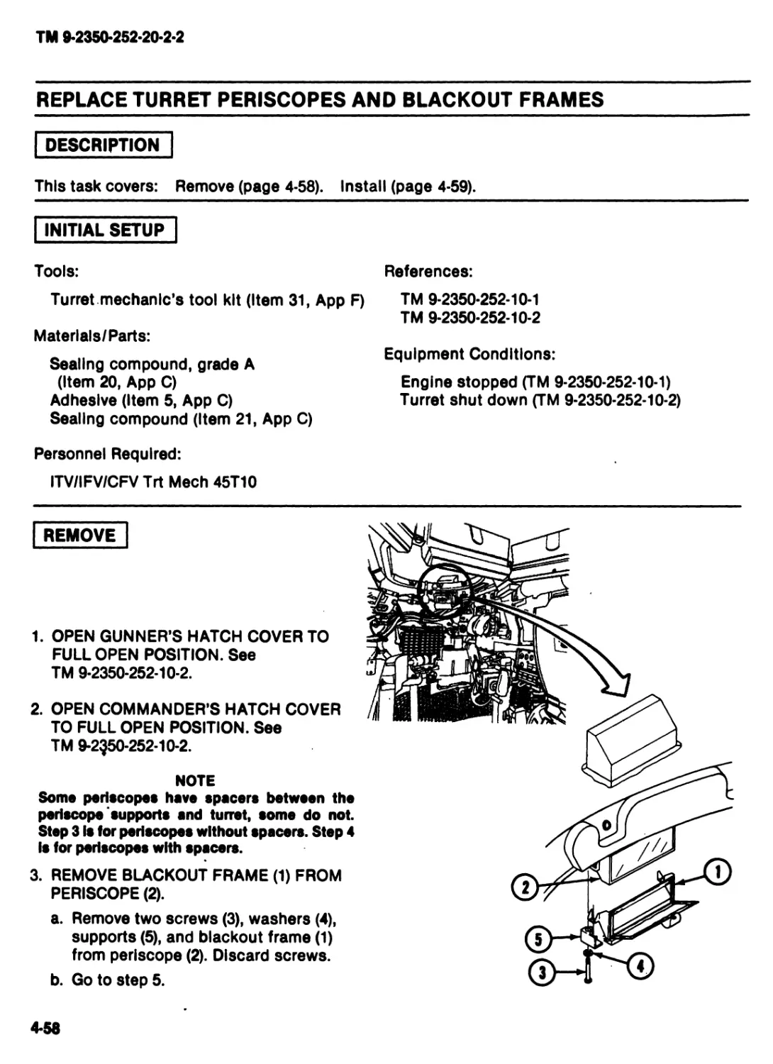
REPLACE TURRET PERISCOPES AND BLACKOUT FRAMES
DESCRIPTION
This task covers: Remove (page 4-58). Install (page 4-59).
INITIAL SETUP
Tools:
Turret mechanic’s tool kit (Item 31, App F)
Materlals/Parts:
Sealing compound, grade A
(Item 20, Арр C)
Adhesive (Item 5, Арр C)
Sealing compound (Item 21, Арр C)
Personnel Required:
ITV/IFV/CFV Trt Meeh 45T10
References:
TM 9-2350-252-10-1
TM 9-2350-252-10-2
Equipment Conditions:
Engine stopped (TM 9-2350-252-10-1)
Turret shut down (TM 9-2350-252-10-2)
REMOVE
1. OPEN GUNNER’S HATCH COVER TO
FULL OPEN POSITION. See
TM 9-2350-252-10-2.
2. OPEN COMMANDER’S HATCH COVER
TO FULL OPEN POSITION. See
TM 9-2550-252-10-2.
NOTE
Some periscopes have spacers between the
periscope supports and turret, some do not.
Step 3 Is for periscopes without spacers. Step 4
Is for periscopes with spacers.
3. REMOVE BLACKOUT FRAME (1) FROM
PERISCOPE (2).
a. Remove two screws (3), washers (4),
supports (5), and blackout frame (1)
from periscope (2). Discard screws.
b. Go to step 5.
4-58
TM 9-2350-252-20-2-2
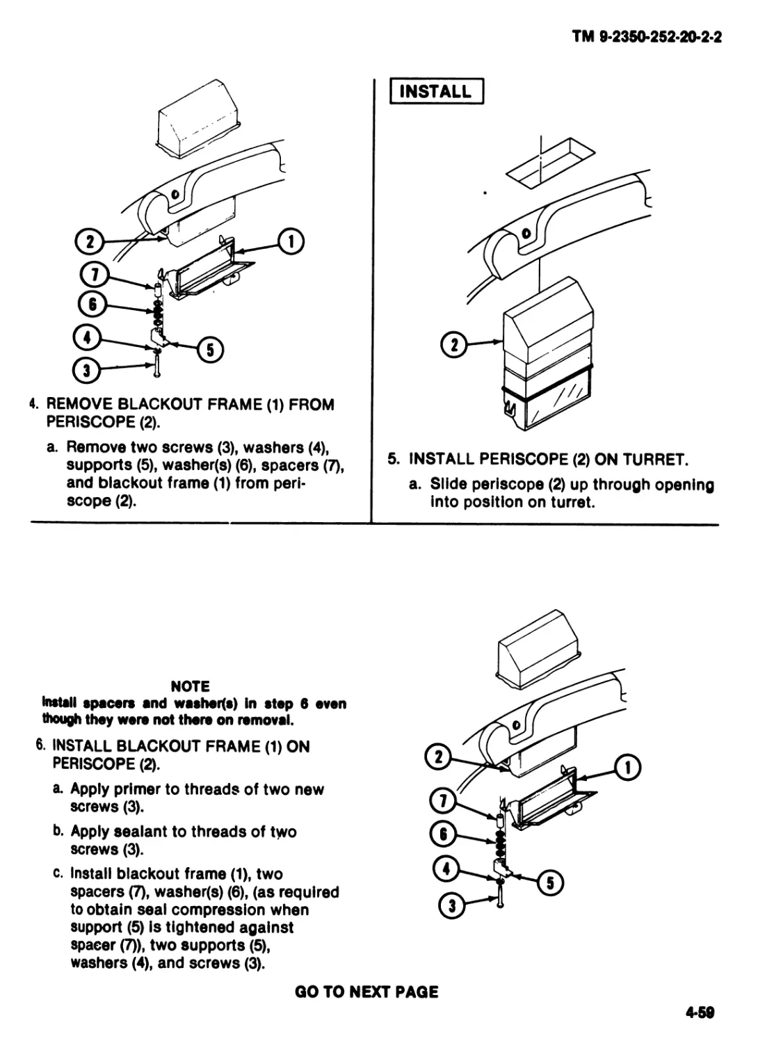
4. REMOVE BLACKOUT FRAME (1) FROM
PERISCOPE (2).
a. Remove two screws (3), washers (4),
supports (5), washer(s) (6), spacers (7),
and blackout frame (1) from peri-
scope (2).
INSTALL
5. INSTALL PERISCOPE (2) ON TURRET.
a. Slide periscope (2) up through opening
into position on turret.
NOTE
Install spacers and washed*) in step 6 even
though they were not there on removal.
6. INSTALL BLACKOUT FRAME (1) ON
PERISCOPE (2).
a. Apply primer to threads of two new
screws (3).
b. Apply sealant to threads of two
screws (3).
c. Install blackout frame (1), two
spacers (7), washer(s) (6), (as required
to obtain seal compression when
support (5) is tightened against
spacer (7)), two supports (5),
washers (4), and screws (3).
QO TO NEXT PAGE
4-59
TM 9-2350-252-20-2-2
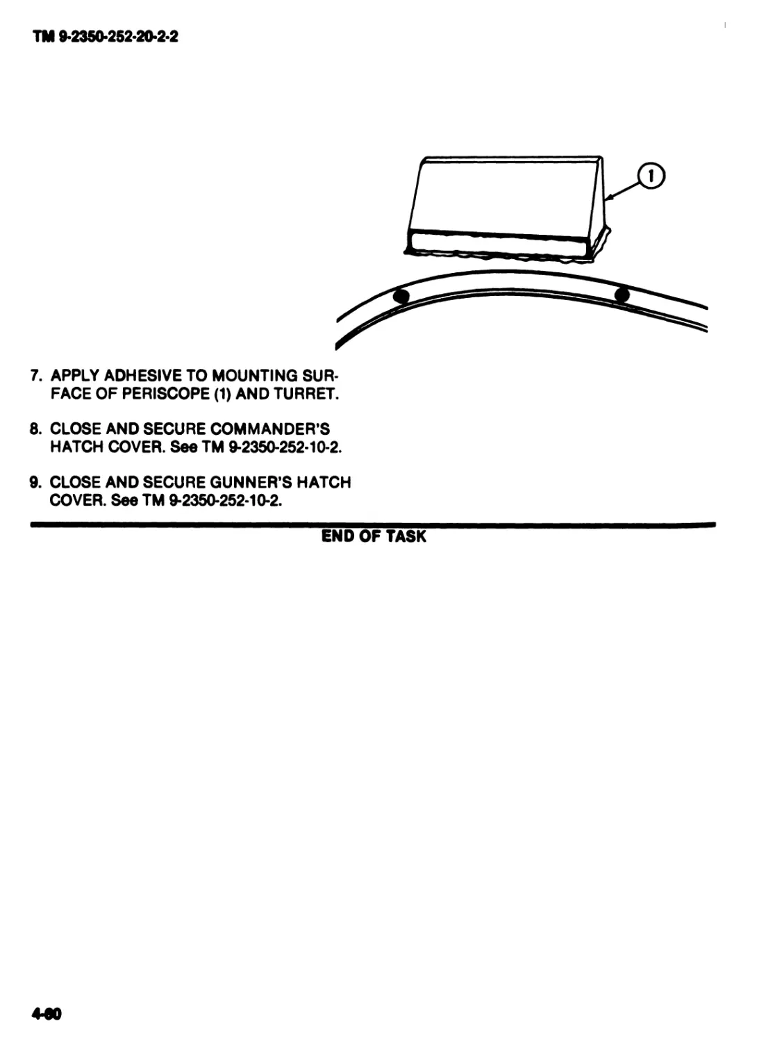
7. APPLY ADHESIVE TO MOUNTING SUR-
FACE OF PERISCOPE (1) AND TURRET.
8. CLOSE AND SECURE COMMANDER’S
HATCH COVER. See TM 9-2350-252-10-2.
9. CLOSE AND SECURE GUNNER’S HATCH
COVER. See TM 9-2350-252-10-2.
END OF TASK
440
TM 9-2350-252-20-2-2
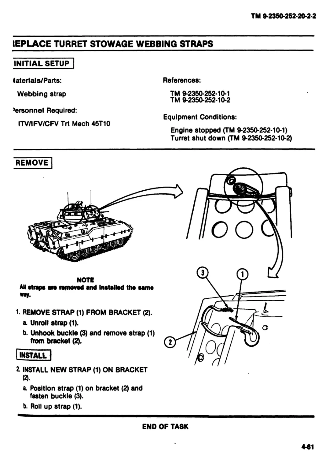
IEPLACE TURRET STOWAGE WEBBING STRAPS
INITIAL SETUP
taterials/Parts:
References:
Webbing strap
>ersonnel Required:
ITV/IFV/CFV Trt Meeh 45T10
TM 9-2350-252-10-1
TM 9-2350-252-10-2
Equipment Conditions:
Engine stopped (TM 9-2350-252-10-1)
Turret shut down (TM 9-2350-252-10-2)
REMOVE
NOTE
AN straps are removed and Installed tho same
1. REMOVE STRAP (1) FROM BRACKET (2).
a. Unroll strep (1).
b. Unhook buckle (3) and remove strap (1)
from bracket (2).
Install I
2. INSTALL NEW STRAP (1) ON BRACKET
(2) .
a. Position strap (1) on bracket (2) and
fasten buckle (3).
b. Roll up strap (1).
END OF TASK
4-61
TM 9-2350-252-20-2-2
REPLACE OUTSIDE TURRET AMMO BRACKETS
DESCRIPTION
This task covers: Remove (page 4-62). Install (page 4-63).
INITIAL SETUP
Tools:
References:
Turret mechanic’s tool kit (Item 31, App F)
Materials/Parts:
Ammo bracket
Ammo bracket
Personnel Required:
ITV/IFV/CFV Trt Meeh 45T10
TM 9-2350-252-10-1
TM 9-2350-252-10-2
Equipment Conditions:
Engine stopped (TM 9-2350-252-10-1)
Turret shut down (TM 9-2350-252-10-2)
REMOVE
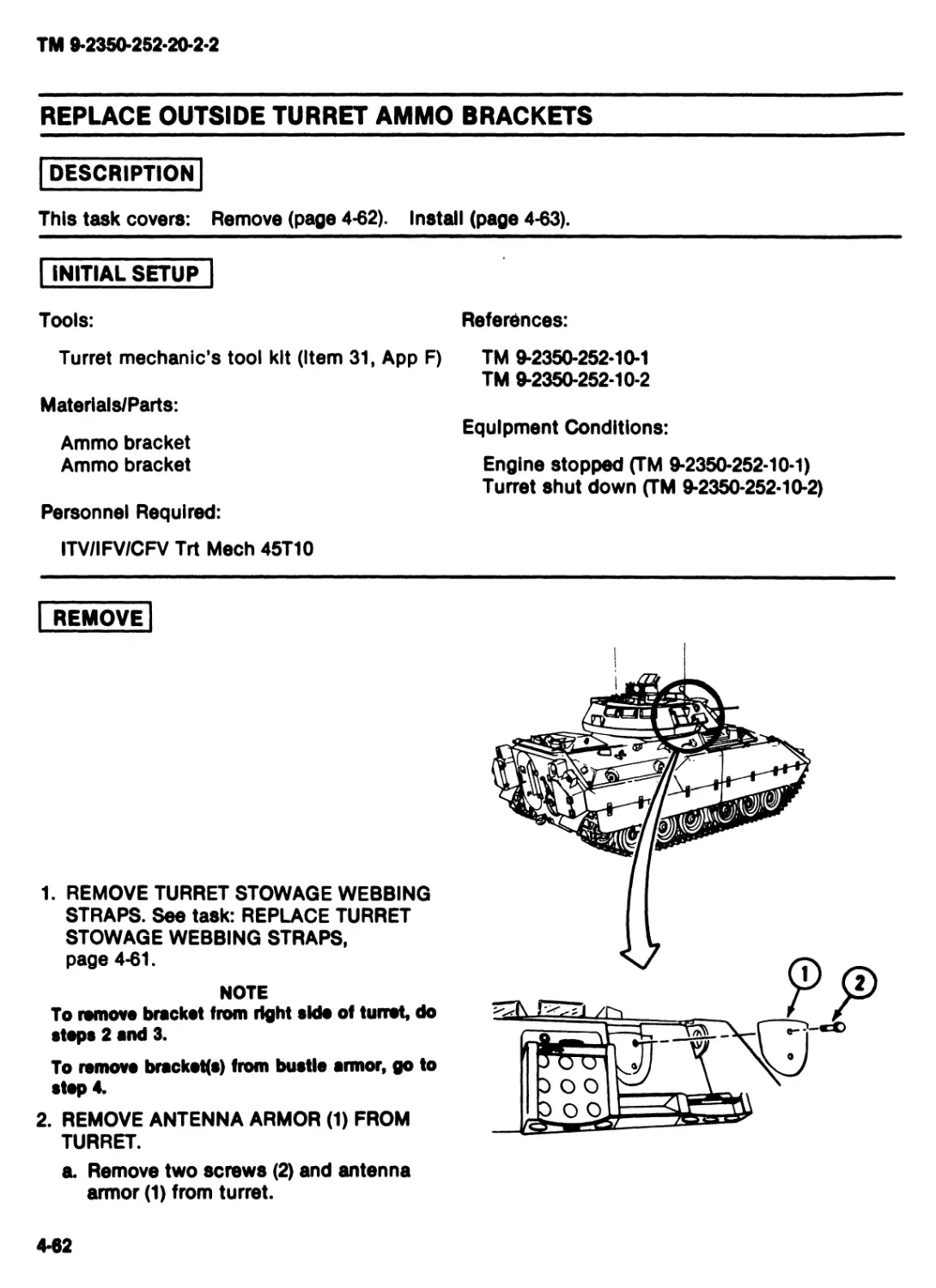
1. REMOVE TURRET STOWAGE WEBBING
STRAPS. See task: REPLACE TURRET
STOWAGE WEBBING STRAPS,
page 4-61.
NOTE
To remove bracket from right side of turret, do
steps 2 and 3.
To remove brackets) from bustle armor, go to
step 4.
2. REMOVE ANTENNA ARMOR (1) FROM
TURRET.
a. Remove two screws (2) and antenna
armor (1) from turret.
4-62
TM 9-2350-252-20-2-2
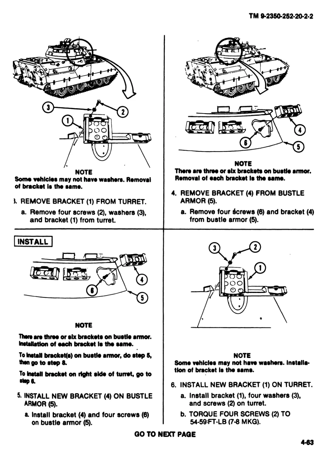
NOTE
Somo vehicle* may not have washers. Removal
of bracket is the same.
I. REMOVE BRACKET (1) FROM TURRET.
a. Remove four screws (2), washers (3),
and bracket (1) from turret.
NOTE
There are three or elx brackets on bustle armor.
Removal of each bracket Is tho samo.
4. REMOVE BRACKET (4) FROM BUSTLE
ARMOR (5).
a. Remove four Screws (6) and bracket (4)
from bustle armor (5).
INSTALL
NOTE
There are throe or six brackets on bustle armor,
installation of each bracket Is the samo.
To Install brackets) on bustle armor, do stop 5,
then go to step 8.
To Install bracket on right side of turret, go to
•tape.
5. INSTALL NEW BRACKET (4) ON BUSTLE
ARMOR (5).
a Install bracket (4) and four screws (6)
on bustle armor (5).
NOTE
Some vehicles may not have washers. Installs*
tlon of bracket Is the same.
6. INSTALL NEW BRACKET (1) ON TURRET.
a. Install bracket (1), four washers (3),
and screws (2) on turret.
b. TORQUE FOUR SCREWS (2) TO
54-59 FT-LB (7-8 MKG).
GO TO NEXT PAGE
4-63
TM 9-2350-252-20-2-2
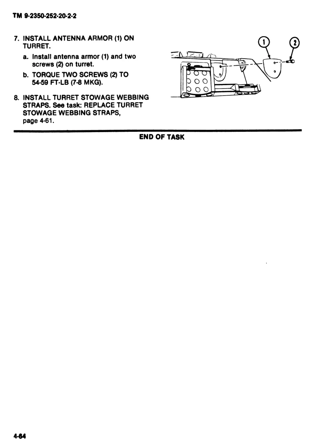
7. INSTALL ANTENNA ARMOR (1) ON
TURRET.
a. Install antenna armor (1) and two
screws (2) on turret.
b. TORQUE TWO SCREWS (2) TO
54-59 FT-LB (7-8 MKG).
8. INSTALL TURRET STOWAGE WEBBING
STRAPS. See task: REPLACE TURRET
STOWAGE WEBBING STRAPS,
page 4-61.
END OF TASK
444
TM 9-2350*252-20-2-2
REPLACE VEHICLE ACCESSORY BOX
INITIAL SETUP
Tools: References:
Turret mechanic’s tool kit (Item 31, App F) TM 9-2350*252-10-1
TM 9-2350-252-10-2
Materials/Parts:
Equipment Conditions:
Vehicular accessory box
Engine stopped (TM 9-2350-252-10-1)
Personnel Required: Turret shut down (TM 9-2350-252-10-2)
ITV/IFV/CFV Trt Meeh 45T10
REMOVE
INSTALL
3
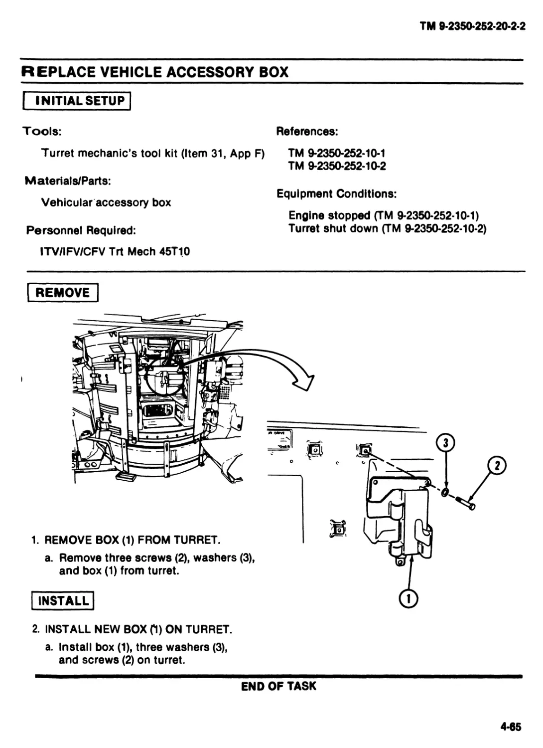
1. REMOVE BOX (1) FROM TURRET.
a. Remove three screws (2), washers (3),
and box (1) from turret.
2. INSTALL NEW BOX fl) ON TURRET.
a. Install box (1), three washers (3),
and screws (2) on turret.
END OF TASK
4-65
TM 9-2350-252-20-2-2
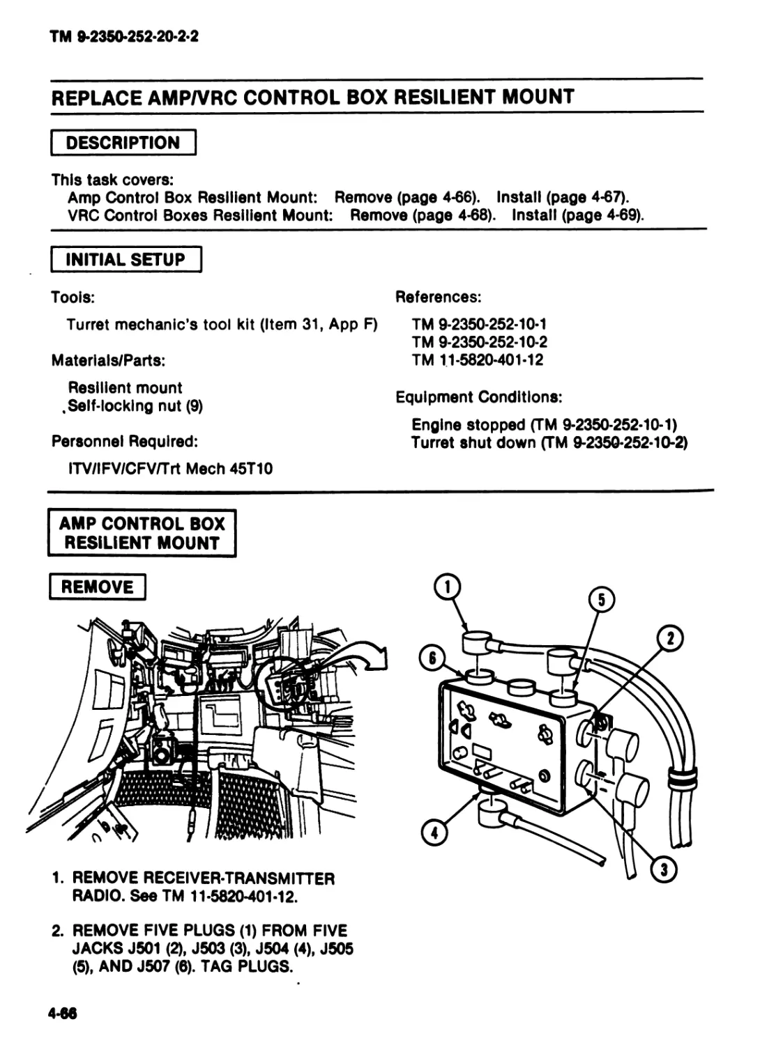
REPLACE AMP/VRC CONTROL BOX RESILIENT MOUNT
DESCRIPTION
This task covers:
Amp Control Box Resilient Mount: Remove (page 4-66). Install (page 4-67).
VRC Control Boxes Resilient Mount: Remove (page 4-68). Install (page 4-69).
INITIAL SETUP
Tools:
References:
Turret mechanic’s tool kit (Item 31, App F)
Materlals/Parts:
Resilient mount
.Self-locking nut (9)
Personnel Required:
ITV/IFV/CFV/Trt Meeh 45T10
TM 9-2350-252-10-1
TM 9-2350-252-10-2
TM 11-5820-401-12
Equipment Conditions:
Engine stopped (TM 9-2350-252-10-1)
Turret shut down (TM 9-2350-252-10-2)
AMP CONTROL BOX
RESILIENT MOUNT
REMOVE
1. REMOVE RECEIVER-TRANSMITTER
RADIO. See TM 11-5820-401-12.
2. REMOVE FIVE PLUGS (1) FROM FIVE
JACKS J501 (2), J503 (3), J504 (4), J505
(5), AND J507 (6). TAG PLUGS.
4-66
TM 9*2350«252*20*2*2
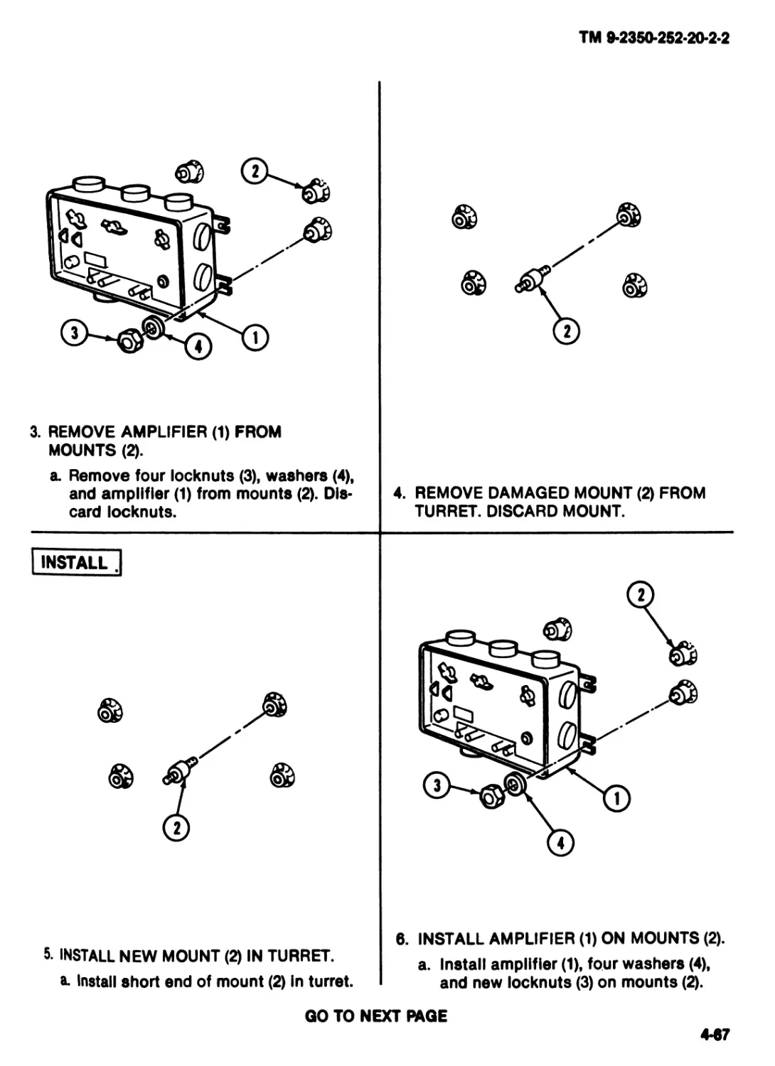
3. REMOVE AMPLIFIER (1) FROM
MOUNTS (2).
a. Remove four locknuts (3), washers (4),
and amplifier (1) from mounts (2). Dis*
card locknuts.
4. REMOVE DAMAGED MOUNT (2) FROM
TURRET. DISCARD MOUNT.
5. INSTALL NEW MOUNT (2) IN TURRET,
a* Install short end of mount (2) in turret.
6. INSTALL AMPLIFIER (1) ON MOUNTS (2).
a. Install amplifier (1), four washers (4),
and new locknuts (3) on mounts (2).
GO TO NEXT PAGE
4*67
TM 9-2350-252-20-2-2
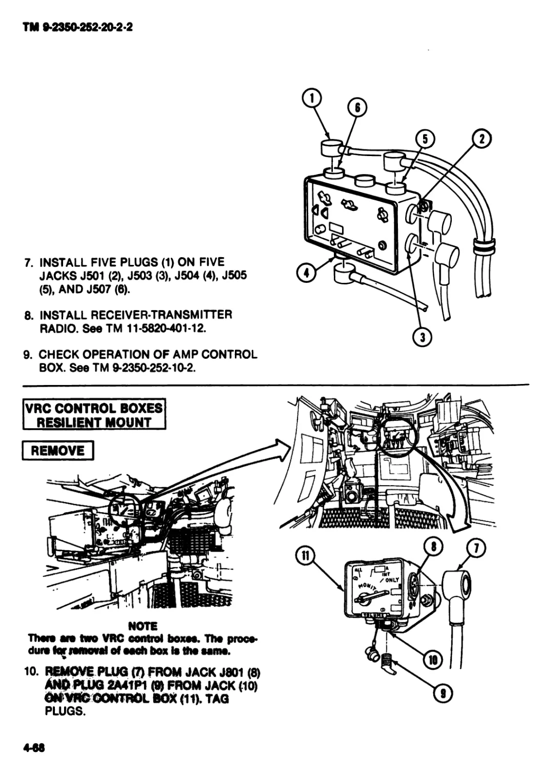
7. INSTALL FIVE PLUGS (1) ON FIVE
JACKS J501 (2), J503 (3), J504 (4), J505
(5), AND J507 (6).
8. INSTALL RECEIVER-TRANSMITTER
RADIO. See TM 11-5820-401-12.
9. CHECK OPERATION OF AMP CONTROL
BOX. See TM 9-2350-252-10-2.
VRC CONTROL BOXES
RESILIENT MOUNT
REMOVE |
' ZOHLT
—1
NOTE
There ere two VRC control boxes. Tho proce-
dure lor removal of each box Is tho ешпо.
10. REMOVE PLUG (7) FROM JACK J801 (8)
ANO PLUG 2A41P1 (9) FROM JACK (10)
ONVRCCONTROL BOX (11). TAG
PLUGS.
4-88
TM 9-2350-252-20-2-2
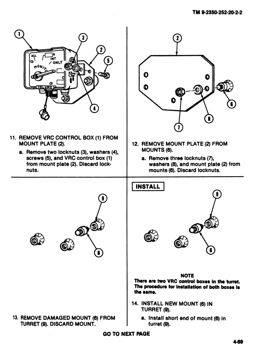
11. REMOVE VRC CONTROL BOX (1) FROM
MOUNT PLATE (2).
a. Remove two locknuts (3), washers (4),
screws (5), and VRC control box (1)
from mount plate (2). Discard lock-
nuts.
12. REMOVE MOUNT PLATE (2) FROM
MOUNTS (6).
a. Remove three locknuts (7),
washers (8), and mount plate (2) from
mounts (8). Discard locknuts.
INSTALL
13. REMOVE DAMAGED MOUNT (6) FROM
TURRET (9). DISCARD MOUNT.
NOTE
There are two VRC control boxes In the turret
The procedure for Installation of both boxes Is
tho same.
14. INSTALL NEW MOUNT (6) IN
TURRET (9).
a. Install short end of mount (6) In
turret (9).
GO TO NEXT RAGE
4-89
TM 9*2350-252-20-2-2
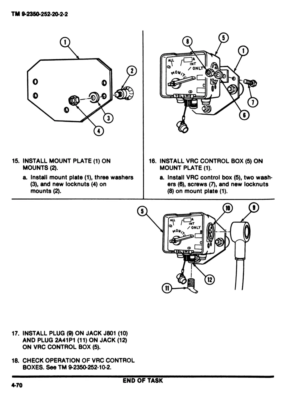
15. INSTALL MOUNT PLATE (1) ON
MOUNTS (2).
a. Install mount plate (1), three washers
(3), and new locknuts (4) on
mounts (2).
16. INSTALL VRC CONTROL BOX (5) ON
MOUNT PLATE (1).
a. Install VRC control box (5), two wash-
ers (6), screws (7), and new locknuts
(8) on mount plate (1).
17. INSTALL PLUG (9) ON JACK J801 (10)
AND PLUG 2A41P1 (11) ON JACK (12)
ON VRC CONTROL BOX (5).
18. CHECK OPERATION OF VRC CONTROL
BOXES. See TM 9-2350-252-10-2.
END OF TASK
4*70
TM 9-2350-252-20-2-2
REPLACE COMMANDER’S BOW HANDLE
DESCRIPTION
This task covers: Remove (page 4-71). Install (page 4-72).
INITIAL SETUP
Tools:
References:
Turret mechanic’s tool kit (Item 31, App F)
TM 9-2350-252-10-1
TM 9-2350-252-10-2
Materials/Parts:
Bow handle
Personnel Required:
ITV/IFV/CFV Trt Meeh 45T10
Equipment Conditions:
Engine stopped (TM 9-2350-252-10-1)
Turret shut down (TM 9-2350-252-10-2)
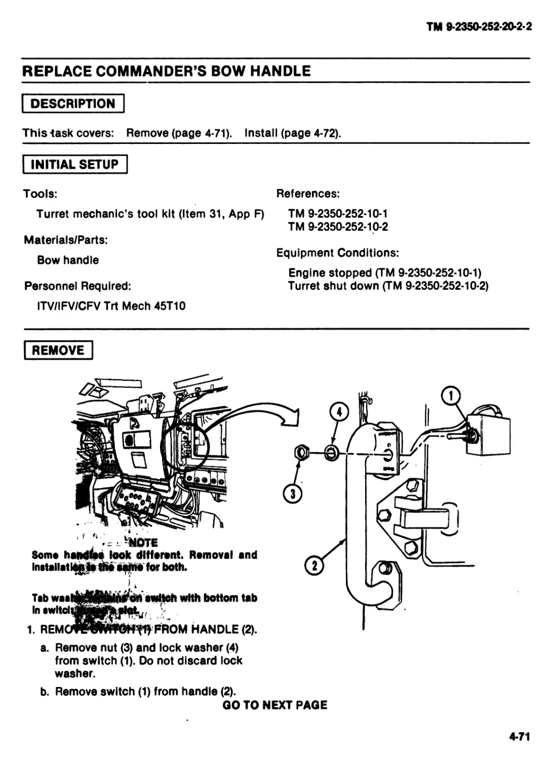
REMOVE
and
VWFROM HANDLE (2).
• --NOTE
Some handles look different. Removal
Installati^s the for both.
switch with bottom tab
Tab waa
In swltdii
1. REM
a. Remove nut (3) and lock washer (4)
from switch (1). Do not discard lock
washer.
b. Remove switch (1) from handle (2).
GO TO NEXT PAGE
4*71
TM 9-2360-252-20-2-2
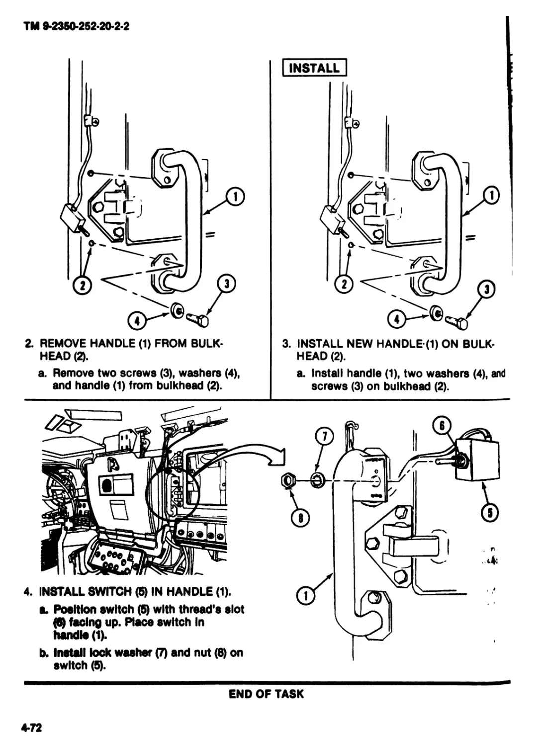
2. REMOVE HANDLE (1) FROM BULK-
HEAD (2).
a. Remove two screws (3), washers (4),
and handle (1) from bulkhead (2).
3. INSTALL NEW HANDLE R) ON BULK-
HEAD (2).
a. Install handle (1), two washers (4), and
screws (3) on bulkhead (2).
b. Install lock washer (7) and nut (8) on
switch
END OF TASK
vn
TM 9-2350-252-20-2-2
REPLACE BORESIGHT BOX TRAY
INITIAL SETUP"
'ools:
References:
Turret mechanic’s tool kit (Item 31, App F)
Jaterials/Parts:
Boresight box tray
Personnel Required:
TM 9*2350-252*10-1
TM 9-2350-252-10-2
Equipment Conditions:
Engine stopped (TM 9-2350-252-10-1)
Turret shut down (TM 9-2350-252-10-2)
ITV/IFV/CFV Trt Meeh 45T10
REMOVE
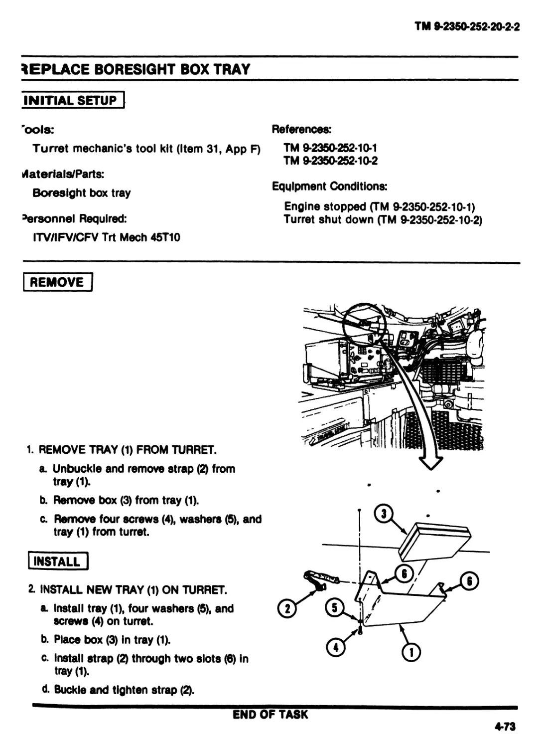
1. REMOVE TRAY (1) FROM TURRET.
a. Unbuckle and remove strap (2) from
tray (1).
b. Remove box (3) from tray (1).
c. Remove four screws (4), washers (5), and
tray (1) from turret.
INSTALL |
2. INSTALL NEW TRAY (1) ON TURRET.
a. Install tray (1), four washers (5), and
screws (4) on turret.
b. Place box (3) In tray (1).
c. Install strap (2) through two slots (6) In
tray (1).
d. Buckle and tighten strap (2).
END OF TASK
4-73
TM 9-2350-252-20-2-2
REPLACE BORESIGHT ADAPTER BAG
INITIAL SETUP
Materials/Parts:
Tools and spare bag
Personnel Required:
ITV/IFV/CFV Trt Meeh 45T10
References:
TM 9-2350-252-10-1
TM 9-2350-252-10-2
Equipment Conditions:
Engine stopped (TM 9-2350-252-10-1)
Turret shut down (TM 9-2350-252-10-2)
Weapons unloaded and safe
(TM 9-2350-252-10-2)
REMOVE
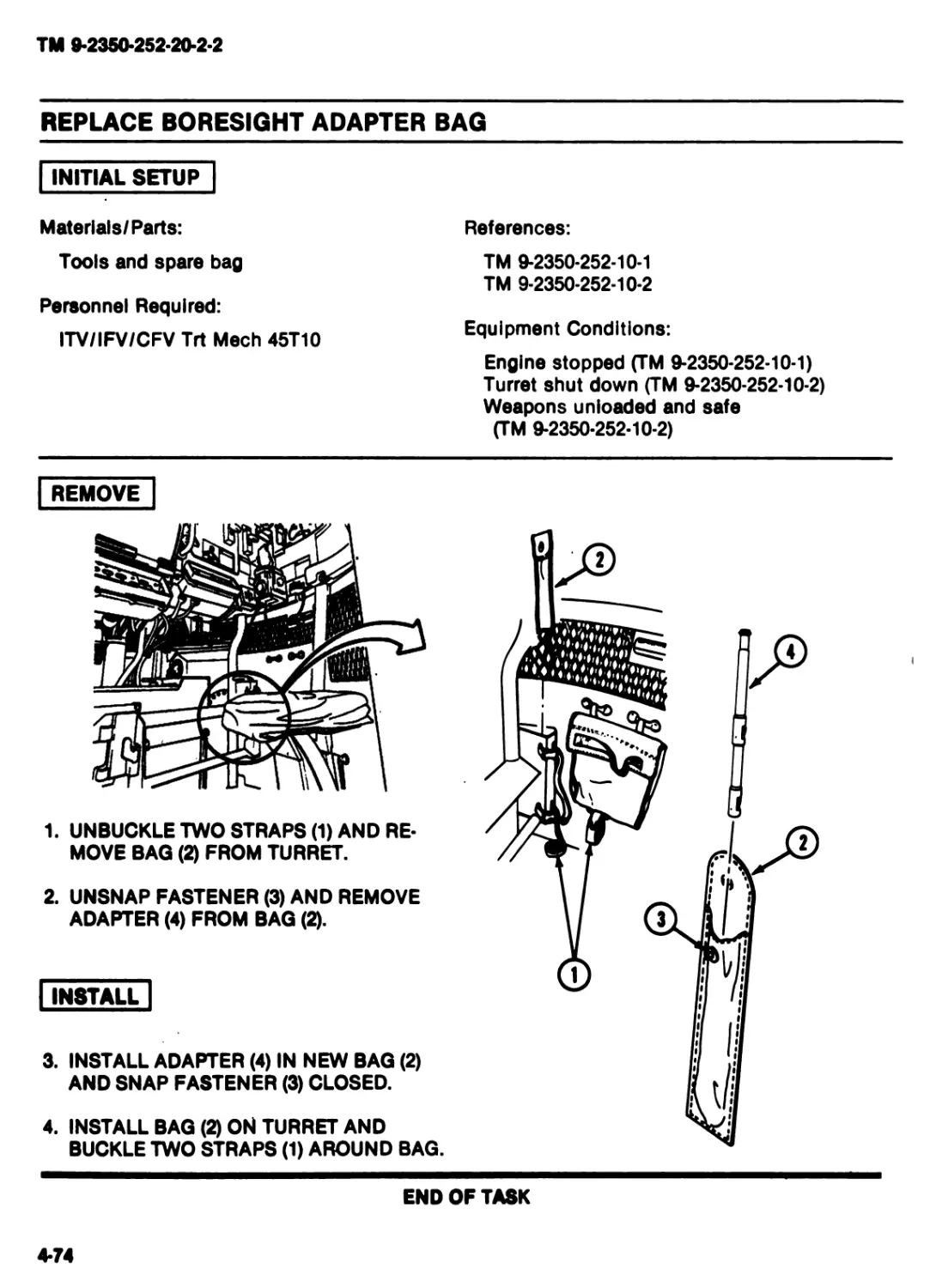
1. UNBUCKLE TWO STRAPS (1) AND RE-
MOVE BAG (2) FROM TURRET.
2. UNSNAP FASTENER (3) AND REMOVE
ADAPTER (4) FROM BAG (2).
I INSTALL |
3. INSTALL ADAPTER (4) IN NEW BAG (2)
AND SNAP FASTENER (3) CLOSED.
4. INSTALL BAG (2) ON TURRET AND
BUCKLE TWO STRAPS (1) AROUND BAG.
END OF TASK
4-74
TM 9-2350-252-20-2-2
PLACE ANTENNA MOUNT COVER
ITIAL SETUP
References:
urret mechanic’s tool kit (Item 31, App F)
erials/Parts:
over
elf-locking screw (4)
sonnel Required:
TM 9-2350-252-10-1
TM 9-2350-252-10-2
Equipment Conditions:
Engine stopped (TM 9-2350-252-10-1)
Turret shut down (TM 9-2350-252-10-2)
FV/IFV/CFV Trt Meeh 45T10
EMOVE
INSTALL
REMOVE FOUR SELF-LOCKING SCREWS
(1) AND COVER (2) FROM ANTENNA
MOUNT (3). DISCARD SCREWS AND
COVER.
2. INSTALL NEW COVER (2) AND FOUR
NEW SELF-LOCKING SCREWS (1) ON
ANTENNA MOUNT (3).
END OF TASK
4-75
TM 9-2350-252-20-2-2
REPLACE HELMET HOLDER BRACKET
INITIAL SETUP
Tools:
References:
Turret mechanic’s tool kit (Item 31, App F)
Materials/Parts:
Bracket
Personnel Required:
ITV/IFV/CFV Trt Meeh 45T10
TM 9-2350*252*10-1
TM 9-2350-252-10-2
Equipment Conditions:
Engine stopped (TM 9-2350-252-10-1)
Turret shut down (TM 9-2350-252-10-2)
REMOVE
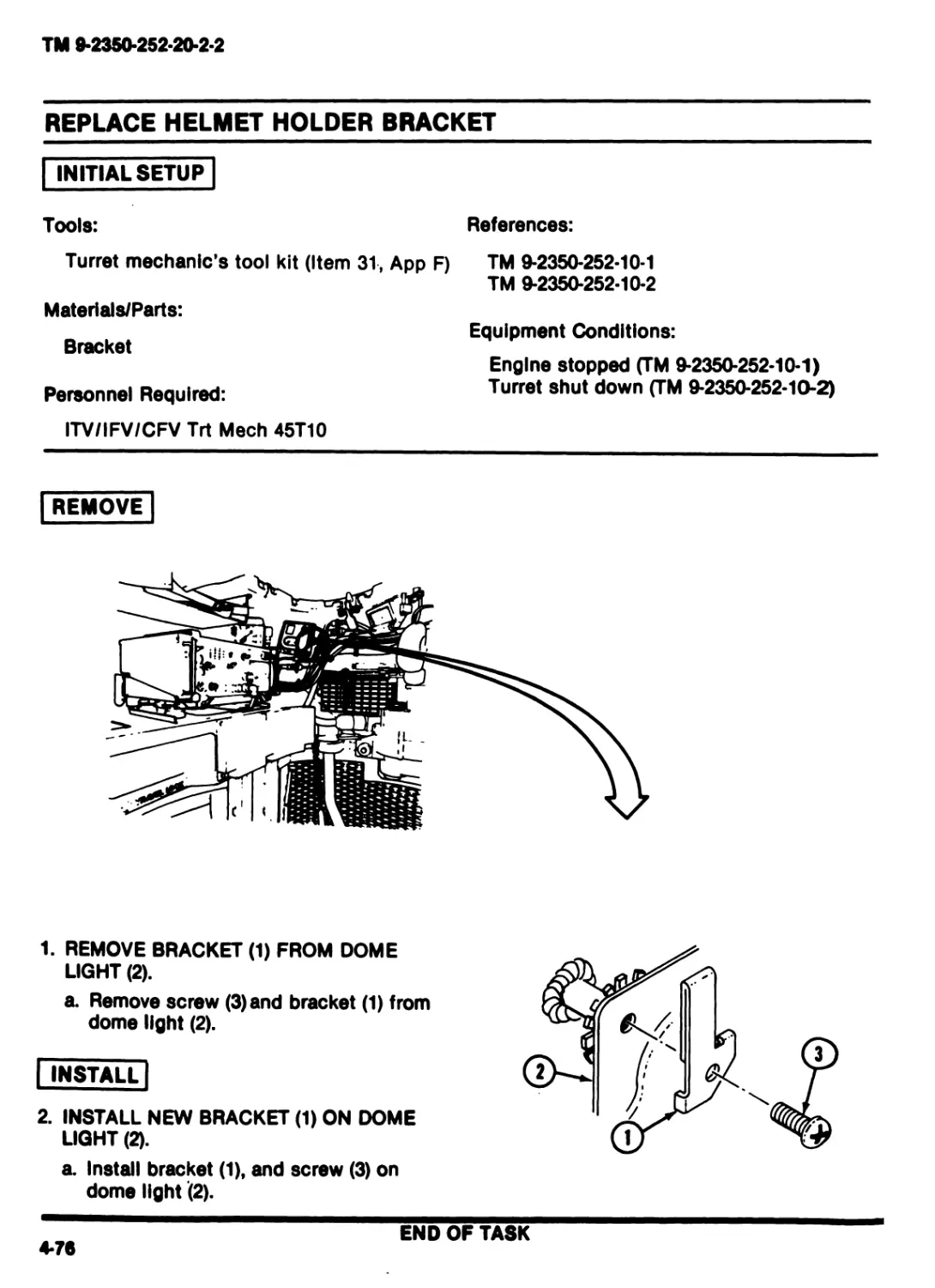
1. REMOVE BRACKET (1) FROM DOME
LIGHT (2).
a. Remove screw (3)and bracket (1) from
dome light (2).
| INSTALL
2. INSTALL NEW BRACKET (1) ON DOME
LIGHT (2).
a. Install bracket (1), and screw (3) on
dome light (2).
END OF TASK
4-76
TM 9-2350-252-20-2-2
Section VII. MAINTENANCE OF COMMANDER’S/GUNNER’S SEAT
TASK INDEX
Task Page
Replace Commander's Seat
Assembly .......................4-78
Replace Commander’s Seat
Cushion.........................4-81
Replace Commander’s/Gunner’s
Seat Extension Springs .........4-82
Replace Commander’s/Gunner’s
Lap Safety Belt.................4-83
Replace Commander’s Seat
Platform........................4-84
Task Page
Replace Commander’s/Gunner’s
Seat Quick Release Pin ...........4-86
Replace Gunner’s Seat
Assembly ........................ 4-87
Replace Gunner’s Seat
Cushion...........................4-90
Replace Gunner’s Seat............4-91
Replace Gunner’s Seat
Platform..........................4-92
4-77
TM 9-2350-252-20-2-2
REPLACE COMMANDER’S SEAT ASSEMBLY
description!
This task covers: Remove (page 4*78). Install (page 4-79).
INITIAL SETUP
Tools:
References:
Turret mechanic's tool kit (Item 31, App F)
Materials/Parts:
Lock washer (2)
Self-locking nut (2)
Commander's seat assembly
TM 9-2350-252-10-1
TM 9-2350-252-10-2
Equipment Conditions:
Engine stopped (TM 9-2350-252-10-1)
Turret shut down (TM 9-2350-252-10-2)
Personnel Required:
ITV/IFV/CFV Trt Meeh 45T10
Helper (H)
REMOVE
3
3
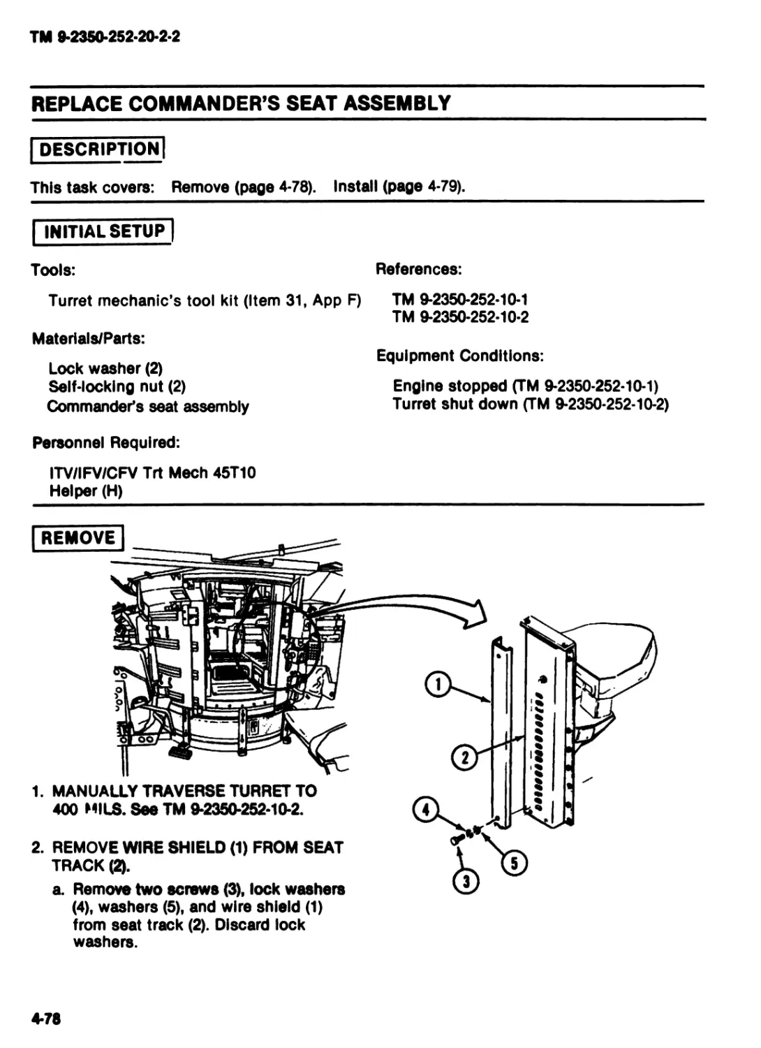
1. MANUALLY TRAVERSE TURRET TO
400 MILS. See TM 9-2350-252-10-2.
2. REMOVE WIRE SHIELD (1) FROM SEAT
TRACK (Q.
a. Remove two screws (3), lock washers
(4), washers (5), and wire shield (1)
from seat track (2). Discard lock
washers.
4-78
TM 9-2350-252-20-2-2
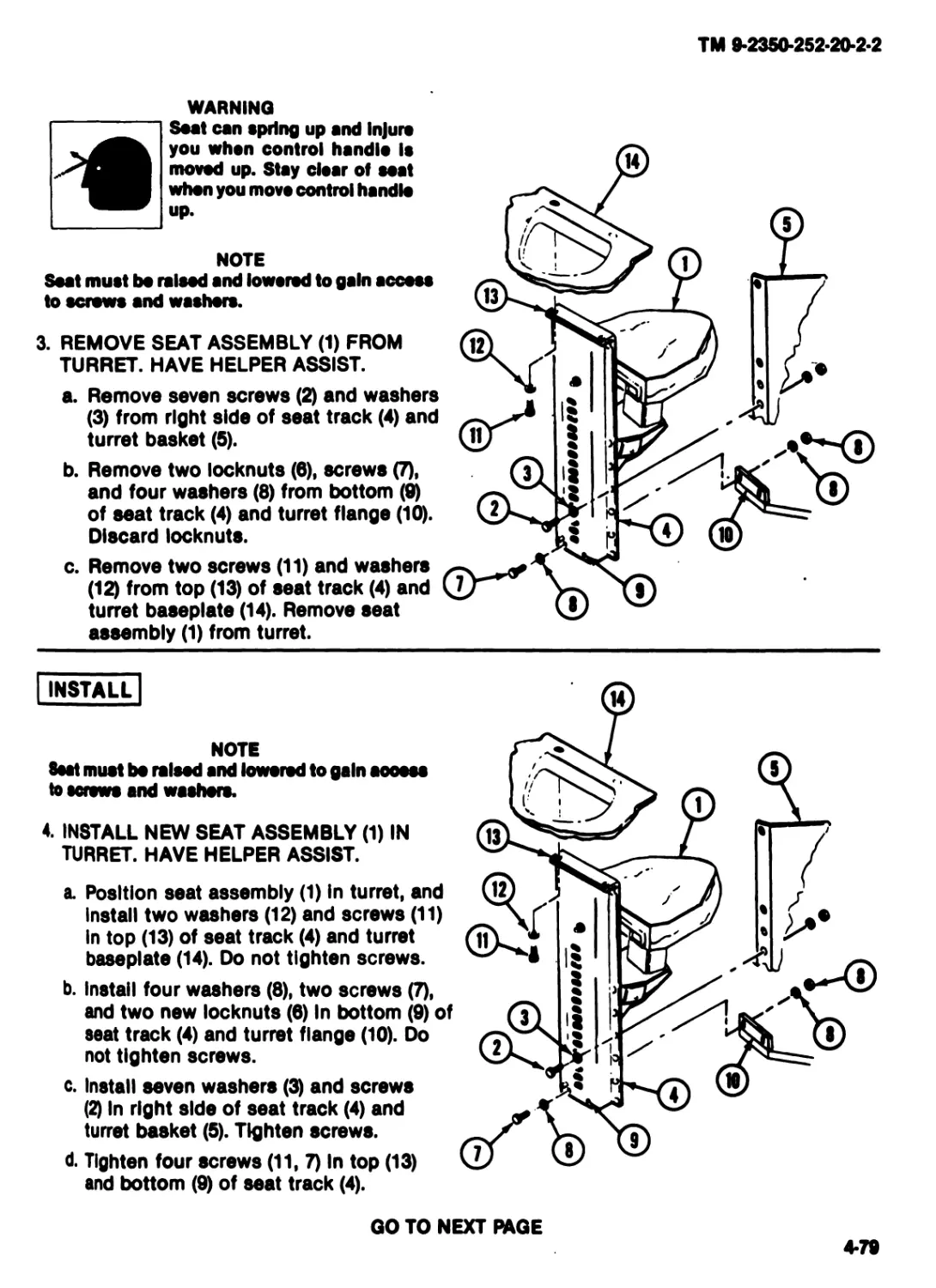
WARNING
Seat can spring up and Injure
you whan control handle Is
moved up. Stay clear of eoat
when you move control handle
up.
NOTE
Seat must bo raised and lowered to gain access
to screws and washers.
3. REMOVE SEAT ASSEMBLY (1) FROM
TURRET. HAVE HELPER ASSIST.
a. Remove seven screws (2) and washers
(3) from right side of seat track (4) and
turret basket (5).
b. Remove two locknuts (6), screws (7),
and four washers (8) from bottom (9)
of seat track (4) and turret flange (10).
Discard locknuts.
c. Remove two screws (11) and washers
(12) from top (13) of seat track (4) and
turret baseplate (14). Remove seat
assembly (1) from turret.
INSTALL
NOTE
test must bo raised and lowered to gain aoooos
to screws and washers.
4. INSTALL NEW SEAT ASSEMBLY (1) IN
TURRET. HAVE HELPER ASSIST.
a. Position seat assembly (1) in turret, and
Install two washers (12) and screws (11)
In top (13) of seat track (4) and turret
baseplate (14). Do not tighten screws.
b. Install four washers (8), two screws (7),
and two new locknuts (6) In bottom (9) of
seat track (4) and turret flange (10). Do
not tighten screws.
c. Install seven washers (3) and screws
(2) In right side of seat track (4) and
turret basket (5). Tighten screws.
d. Tighten four screws (11, 7) In top (13)
and bottom (9) of seat track (4).
GO TO NEXT PAGE
4-79
TM 9-2350-252-20-2-2
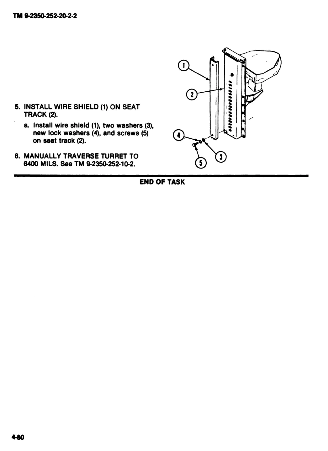
5. INSTALL WIRE SHIELD (1) ON SEAT
TRACK (2).
a. Install wire shield (1), two washers (3),
new lock washers (4), and screws (5)
on seat track (2).
6. MANUALLY TRAVERSE TURRET TO
6400 MILS. See TM 9*2350*252*10-2.
trnmiiimiiii
END OF TASK
4-60
TM 9-2350-252-20-2-2
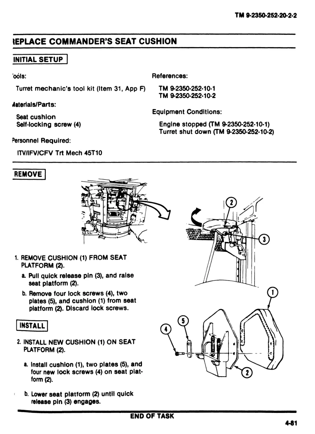
REPLACE COMMANDER’S SEAT CUSHION
INITIAL SETUP
ools:
References:
Turret mechanic’s tool kit (Item 31, App F)
TM 9-2350*252*10-1
TM 9-2350-252-10-2
Haterials/Parts:
Seat cushion
Self-locking screw (4)
Equipment Conditions:
Engine stopped (TM 9-2350-252-10-1)
Turret shut down (TM 9-2350-252-10-2)
Personnel Required:
ITV/IFV/CFV Trt Meeh 45T10
REMOVE
1. REMOVE CUSHION (1) FROM SEAT
PLATFORM (2).
a. Pull quick release pin (3), and raise
seat platform (2).
b. Remove four lock screws (4), two
plates (5), and cushion (1) from seat
platform (2). Discard lock screws.
INSTALL
2. INSTALL NEW CUSHION (1) ON SEAT
PLATFORM (2).
a. Install cushion (1), two plates (5), and
four new lock screws (4) on seat plat-
form (2).
b. Lower seat platform (2) until quick
release pin (3) engages.
END OF TASK
4-51
TM 94360*262-20*2-2
REPLACE COMMANDER’S/GUNNER’S SEAT EXTENSION SPRINGS
| INITIAL SETUP"
Tools:
References:
Turret mechanic's tool kit (Item 31, App F)
Materlals/Parts:
Extension spring (2)
Personnel Required:
ITV/IFV/CFV Trt Meeh 45T10
TM 9*2350-252-10-1
TM 9-2350-252-10-2
Equipment Conditions:
Engine stopped (TM 9-2350-252-10-1)
Turret shut down (TM 9-2350-252-10-2)
REMOVE
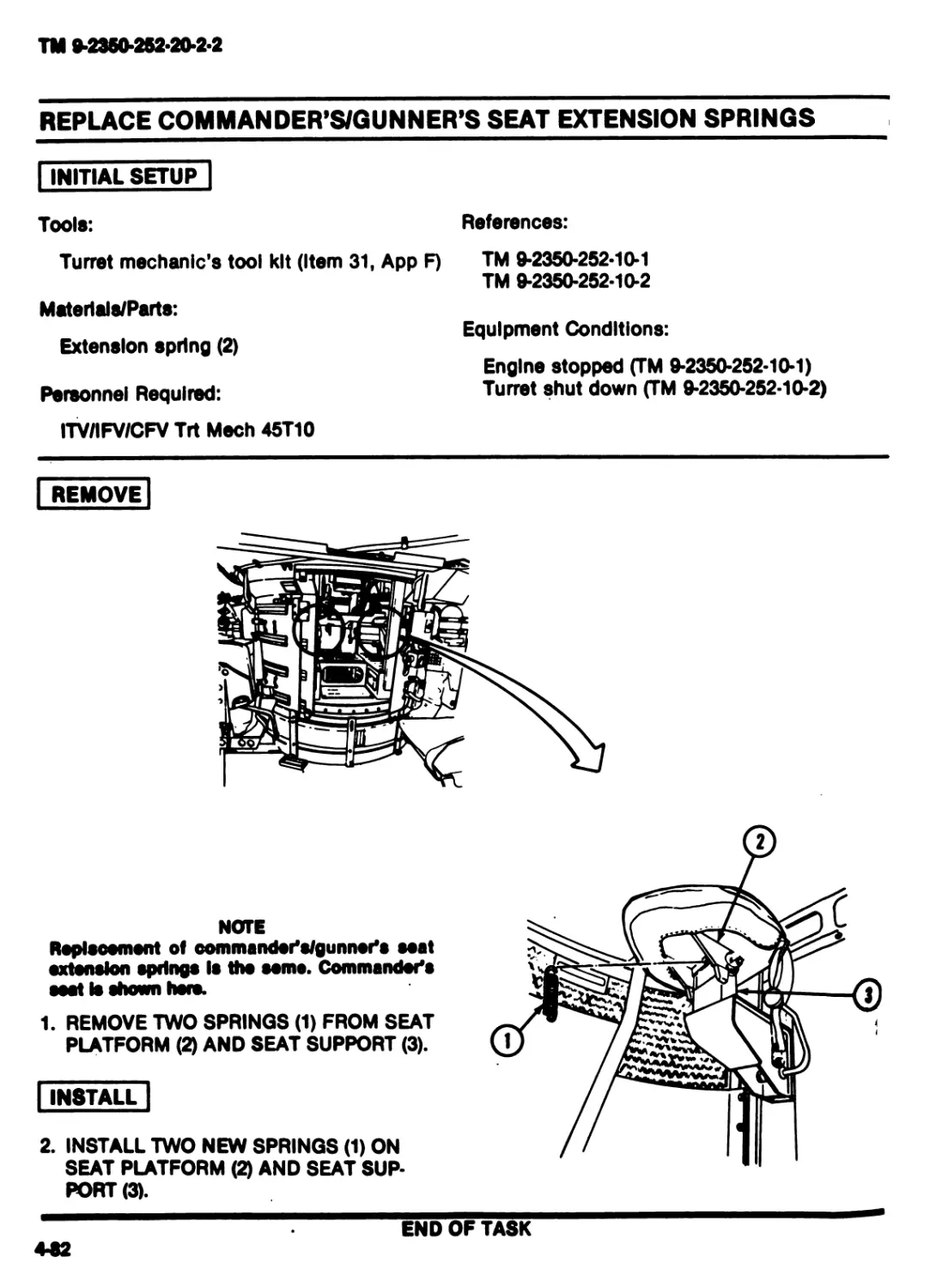
NOTE
Replsoement of oommandor's/gunnor's seat
extension springs Is tho somo. Commander's
seat Is shown horn*
1. REMOVE TWO SPRINGS (1) FROM SEAT
PLATFORM (2) AND SEAT SUPPORT (3).
I INSTALL |
2. INSTALL TWO NEW SPRINGS (1) ON
SEAT PLATFORM (2) AND SEAT SUP-
PORT (3).
END OF TASK
442
TM 9-2350-252-20-2-2
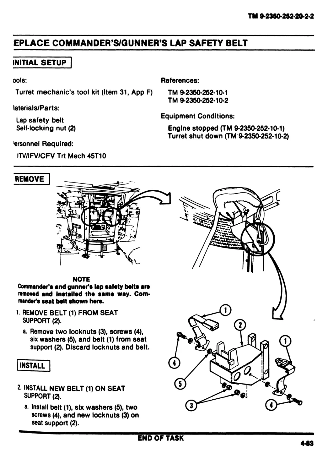
EPLACE COMMANDER’S/GUNNER’S LAP SAFETY BELT
INITIAL SETUP
ools:
References:
Turret mechanic’s tool kit (item 31, App F)
laterials/Parts:
Lap safety belt
Self-locking nut (2)
tersonnel Required:
ITV/IFV/CFV Trt Meeh 45T10
TM 9-2350-252-10-1
TM 9-2350-252-10-2
Equipment Conditions:
Engine stopped (TM 9-2350-252-10-1)
Turret shut down (TM 9-2350-252-10-2)
REMOVE
NOTE
Commander’s and gunner’s lap safety belts are
removed and Installed the same way. Com-
mander’s seat bolt shown hero.
1. REMOVE BELT (1) FROM SEAT
SUPPORT (2).
a. Remove two locknuts (3), screws (4),
six washers (5), and belt (1) from seat
support (2). Discard locknuts and belt.
INSTALL
2. INSTALL NEW BELT (1) ON SEAT
SUPPORT (2).
a. Install belt (1), six washers (5), two
screws (4), and new locknuts (3) bn
seat support (2).
END OF TASK
4-53
TM 9-2350-252-20-2-2
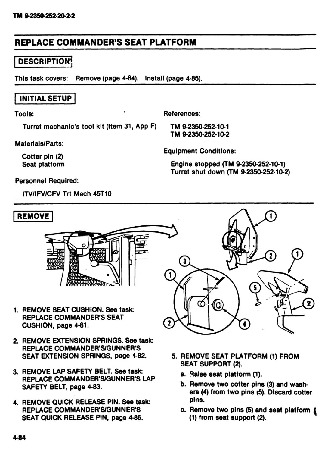
REPLACE COMMANDER’S SEAT PLATFORM
DESCRIPTION?
This task covers: Remove (page 4-84). Install (page 4-85).
INITIAL SETUP
Tools:
References:
Turret mechanic’s tool kit (Item 31, App F)
Materials/Parts:
Cotter pin (2)
Seat platform
Personnel Required:
TM 9-2350-252-10-1
TM 9-2350-252-10-2
Equipment Conditions:
Engine stopped (TM 9-2350-252-10-1)
Turret shut down (TM 9-2350-252-10-2)
ITV/IFV/CFV Trt Meeh 45T10
REMOVE
1. REMOVE SEAT CUSHION. See task:
REPLACE COMMANDER’S SEAT
CUSHION, page 4-81.
2. REMOVE EXTENSION SPRINGS. See task:
REPLACE COMMANDER’S/GUNNER’S
SEAT EXTENSION SPRINGS, page 4-82.
3. REMOVE LAP SAFETY BELT. See task:
REPLACE COMMANDER’S/GUNNER’S LAP
SAFETY BELT, page 4-83.
4. REMOVE QUICK RELEASE PIN. See taste
REPLACE COMMANDER’S/GUNNER’S
SEAT QUICK RELEASE PIN, page 4-86.
5. REMOVE SEAT PLATFORM (1) FROM
SEAT SUPPORT (2).
a. Raise seat platform (1).
b. Remove two cotter pins (3) and wash-
ers (4) from two pins (5). Discard cotter
pins.
c. Remove two pins (5) and seat platform i
(1) from seat support (2).
4-84
тм вдеюдемоде
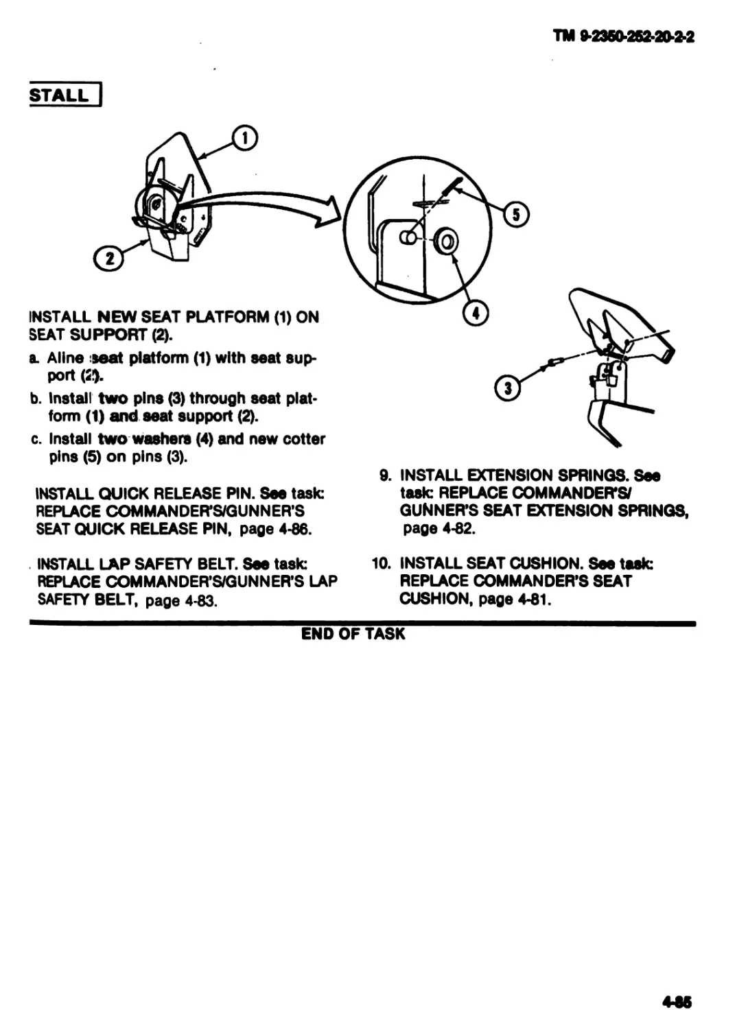
stall |
INSTALL NEW SEAT PLATFORM (1) ON
SEAT SUPPORT (2).
a. Aline seat platform (1) with seat sup-
port (2!).
b. Install two pins (3) through seat plat-
form (1) and seat support (2).
c. Install two washers (4) and new cotter
9. INSTALL EXTENSION SPRINGS. See
pins (5) on pins (3).
INSTALL QUICK RELEASE PIN. See task:
REPLACE COMMANDER’S/GUNNER’S
SEAT QUICK RELEASE PIN, page 4-86.
task: REPLACE COMMANDER’S/
GUNNER’S SEAT EXTENSION SPRINGS,
page 4-82.
INSTALL LAP SAFETY BELT. See task:
REPLACE COMMANDER’S/GUNNER’S LAP
SAFETY BELT, page 4-83.
10. INSTALL SEAT CUSHION. See task:
REPLACE COMMANDER’S SEAT
CUSHION, page 4-81.
END OF TASK
4-86
ТМ 9-2№/МВМ0-Ъ2
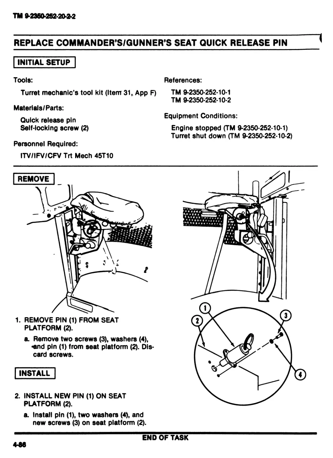
REPLACE COMMANDER’S/GUNNER’S SEAT QUICK RELEASE PIN
INITIAL SETUP
Tools:
References:
Turret mechanic’s tool kit (Item 31, App F)
Materials/Parts:
Quick release pin
Self-locking screw (2)
Personnel Required:
ITV/IFV/CFV Trt Meeh 45T10
TM 9-2350-252-10-1
TM 9-2350-252-10-2
Equipment Conditions:
Engine stopped (TM 9-2350-252-10-1)
Turret shut down (TM 9-2350-252-10-2)
REMOVE
1. REMOVE PIN (1) FROM SEAT
PLATFORM (2).
a. Remove two screws (3), washers (4),
•and pin (1) from seat platform (2). Dis-
card screws.
INSTALL
2. INSTALL NEW PIN (1) ON SEAT
PLATFORM (2).
a. Install pin (1), two washers (4), and
new screws (3) on seat platform (2).
END OF TASK
4-M
TM 9-2360-252-20-2-2
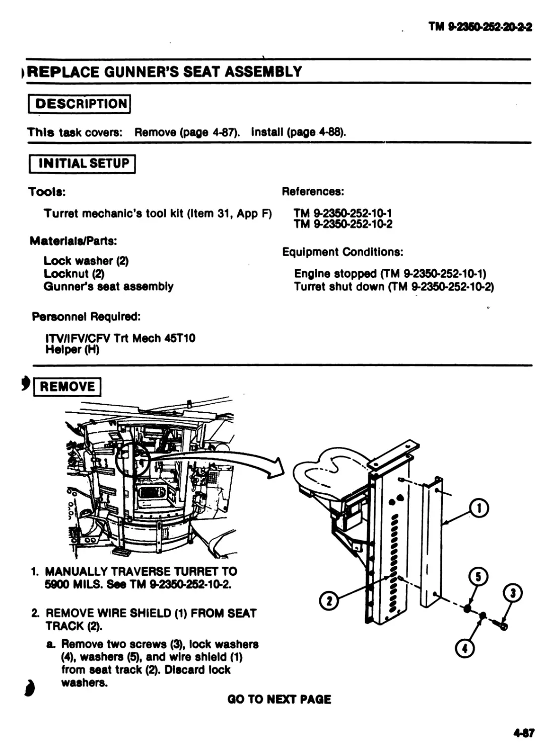
) REPLACE GUNNER’S SEAT ASSEMBLY
DESCRIPTION
This task covers: Remove (page 4-87). Install (page 4-88).
INITIAL SETUP
Tools:
Turret mechanic's tool kit (Item 31,
Materials/Parts:
Lock washer (2)
Locknut (2)
Gunner's seat assembly
Personnel Required:
ITV/IFV/CFV Trt Meeh 45T10
Helper (H)
App F)
References:
TM 9-2350-252-10-1
TM 9-2350-252-10-2
Equipment Conditions:
Engine stopped (TM 9-2350-252-10-1)
Turret shut down (TM 9-2350-252-10-2)
0| REMOVE
1. MANUALLY TRAVERSE TURRET TO
5900 MILS. See TM 9-2350-252-10-2.
2. REMOVE WIRE SHIELD (1) FROM SEAT
TRACK (2).
a. Remove two screws (3), lock washers
(4), washers (5), and wire shield (1)
from seat track (2). Discard lock
к washers.
GO TO NEXT PAGE
4-87
TM 9-2350-252-20-2-2
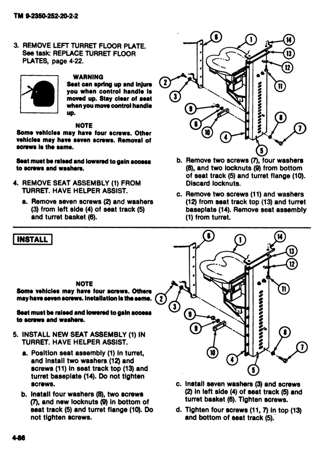
3. REMOVE LEFT TURRET FLOOR PLATE.
See task: REPLACE TURRET FLOOR
PLATES, page 4-22.
WARNING
Seat can spring up and Injure
you when control handle Is
moved up. Stay clear of coat
when you move control handle
up.
NOTE
Some vehicles may have four screws. Other
vehicles may have seven screws. Removal of
screws Is tho same.
Seat must bo raised end lowered to gain access
to screws and washers.
4. REMOVE SEAT ASSEMBLY (1) FROM
TURRET. HAVE HELPER ASSIST.
a. Remove seven screws (2) and washers
(3) from left side (4) of seat track (5)
and turret basket (6).
b. Remove two screws (7), four washers
(8), and two locknuts (9) from bottom
of seat track (5) and turret flange (10).
Discard locknuts.
c. Remove two screws (11) and washers
(12) from seat track top (13) and turret
baseplate (14). Remove seat assembly
(1) from turret.
| INSTALL |
NOTE
Soma vehicles may have four screws. Othere
may have seven screws. Installation Is tho seme.
Seat must bo raised and lowered to gain access
to screws and waahoro.
5. INSTALL NEW SEAT ASSEMBLY (1) IN
TURRET. HAVE HELPER ASSIST.
a. Position seat assembly (1) In turret,
and Install two washers (12) and
screws (11) in seat track top (13) and
turret baseplate (14). Do not tighten
screws.
b. Install four washers (8), two screws
(7), and new locknuts (9) In bottom of
seat track (5) and turret flange (10). Do
not tighten screws.
c. Install seven washers (3) and screws
(2) In left side (4) of seat track (5) and
turret basket (6). Tighten screws.
d. Tighten four screws (11,7) In top (13)
and bottom of seat track (5).
4*86
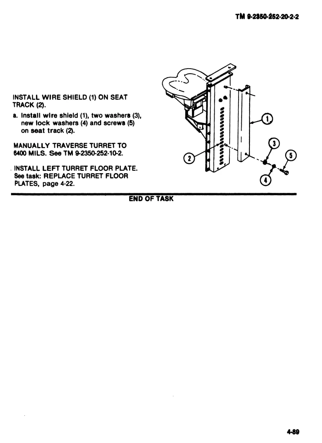
ТМ fl-2350-252-20-2-2
INSTALL WIRE SHIELD (1) ON SEAT
TRACK (2).
a. Install wire shield (1), two washers (3),
new lock washers (4) and screws (5)
on seat track (2).
MANUALLY TRAVERSE TURRET TO
8400 MILS. See TM 9-2350-252-10-2.
INSTALL LEFT TURRET FLOOR PLATE.
See task: REPLACE TURRET FLOOR
PLATES, page 4-22.
END OF TASK
4-89
TM 9-2350-252-20-2-2
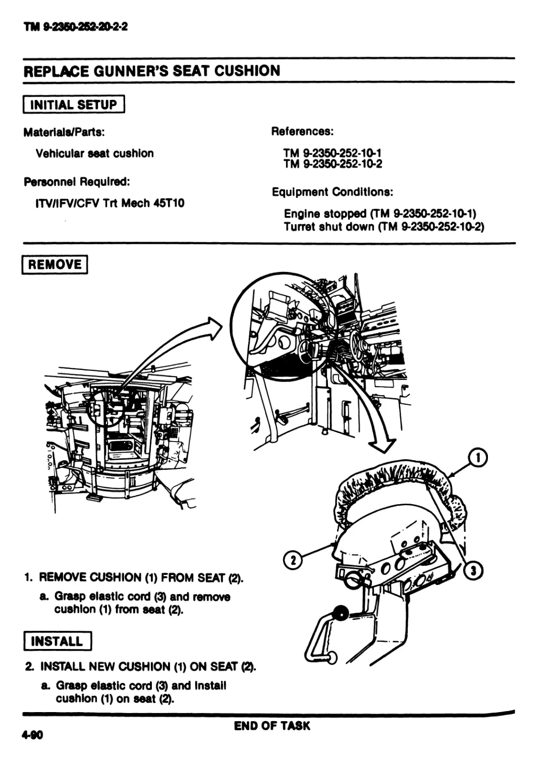
REPLACE GUNNER'S SEAT CUSHION
| INITIAL SETUP
Materials/Parts:
Vehicular seat cushion
Personnel Required:
ITV/IFV/CFV Trt Meeh 45T10
References:
TM 9-2350-252*10*1
TM 9-2350-252-10-2
Equipment Conditions:
Engine stopped (TM 9-2350-252-10-1)
Turret shut down (TM 9-2350-252-10-2)
REMOVE
INSTALL
1. REMOVE CUSHION (1) FROM SEAT (2).
a. Grasp elastic cord (3) and remove
cushion (1) from seat (2).
2. INSTALL NEW CUSHION (1) ON SEAT (2).
a. Grasp elastic cord (3) and Install
cushion (1) on seat (2).
END OF TASK
4-90
ТМ 9-2№0-№ММЯ
REPLACE GUNNER’S SEAT
INITIAL SETUP
Tools:
References:
Turret mechanic’s tool kit (Item 31, App F)
Materials/Parts:
Vehicular seat
Personnel Required:
ITV/IFV/CFV Trt Meeh 45T10
TM 9-2350-252-10*1
TM 9-2350-252-10-2
Equipment Conditions:
Engine stopped (TM 9-2350-252-10-1)
Turret shut down (TM 9-2350-252-10*2)
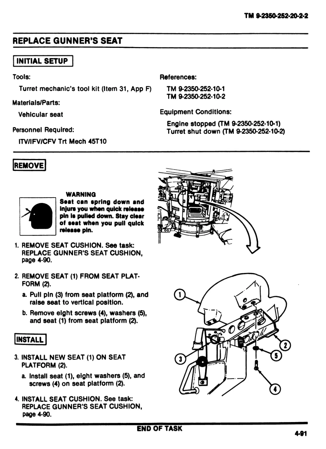
REMOVE |
WARNING
Seat can spring down and
Injurs you when quick release
pin Is pullod down. Stay clear
of seat when you pull quick
release pin.
1. REMOVE SEAT CUSHION. See task:
REPLACE GUNNER’S SEAT CUSHION,
page 4-90.
2. REMOVE SEAT (1) FROM SEAT PLAT-
FORM (2).
a. Pull pin (3) from seat platform (2), and
raise seat to vertical position.
b. Remove eight screws (4), washers (5),
and seat (1) from seat platform (2).
INSTALL
3. INSTALL NEW SEAT (1) ON SEAT
PLATFORM (2).
a Install seat (1), eight washers (5), and
screws (4) on seat platform (2).
4. INSTALL SEAT CUSHION. See task:
REPLACE GUNNER’S SEAT CUSHION,
page 4-90.
END OF TASK
4-91
TM 9-2350-252-20-2-2
REPLACE GUNNER’S SEAT PLATFORM
DESCRIPTION
This task covers: Remove (page 4-92). Install (page 4-93).
INITIAL SETUP
Tools:
References:
Turret mechanic’s tool kit (Item 31, App F) TM 9-2350-252-10-1
TM 9-2350-252-10-2
Materlals/Parts:
_ Equipment Conditions:
Cotter pin (2)
Seat platform Engine stopped (TM 9-2350-252-10-1)
Turret shut down (TM 9-2350-252-10-2)
Personnel Required:
ITV/IFV/CFV Trt Meeh 45T10
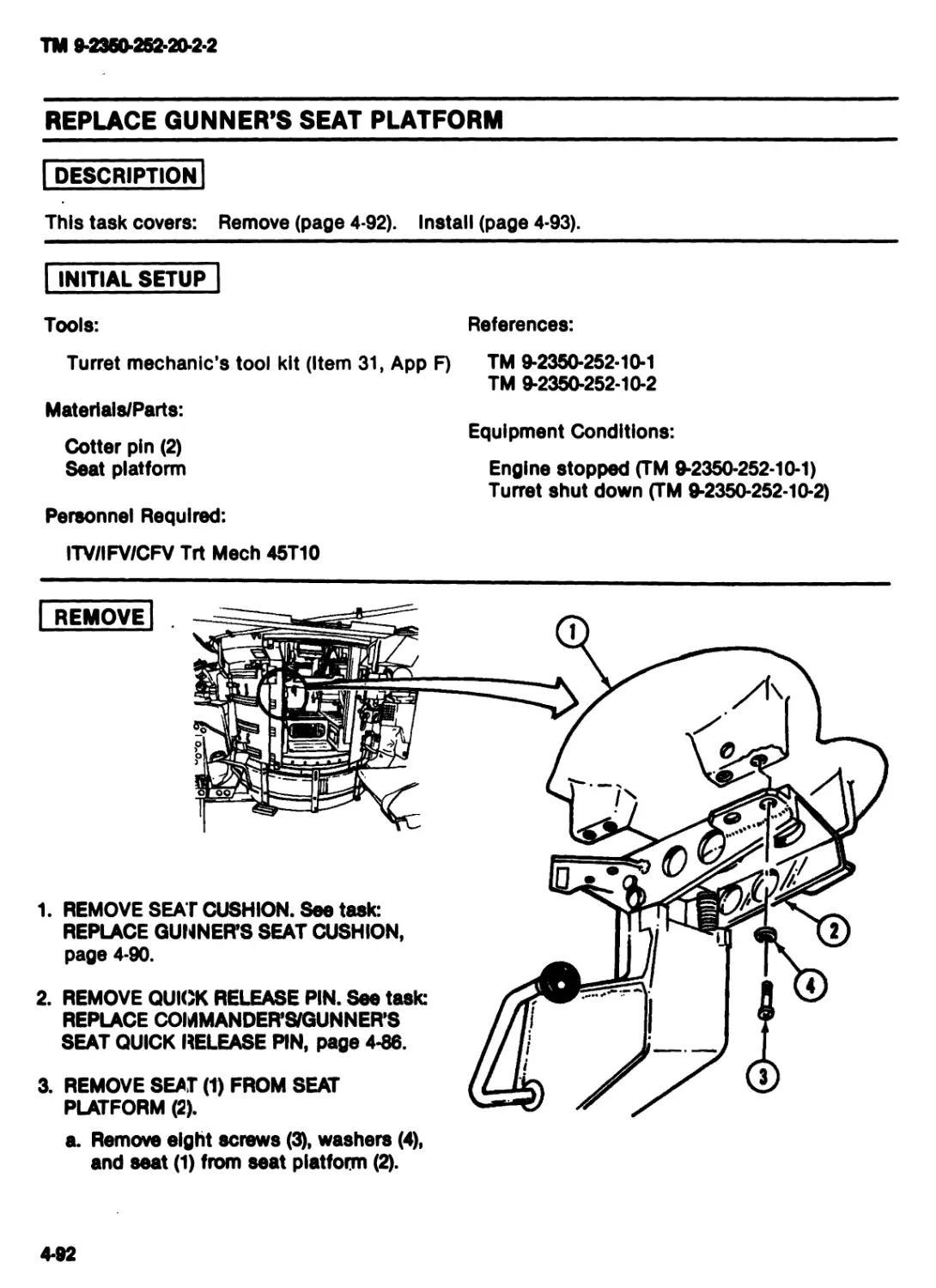
REMOVE
1. REMOVE SEAT CUSHION. See task:
REPLACE GUNNER'S SEAT CUSHION,
page 4-90.
2. REMOVE QUICK RELEASE PIN. See task:
REPLACE COMMANDER’S/GUNNER’S
SEAT QUICK RELEASE PIN, page 4-86.
3. REMOVE SEAT (1) FROM SEAT
PLATFORM (2).
a. Remove eight screws (3), washers (4),
and seat (1) from seat platform (2).
4-92
TM 9-2350-252-20-2-2
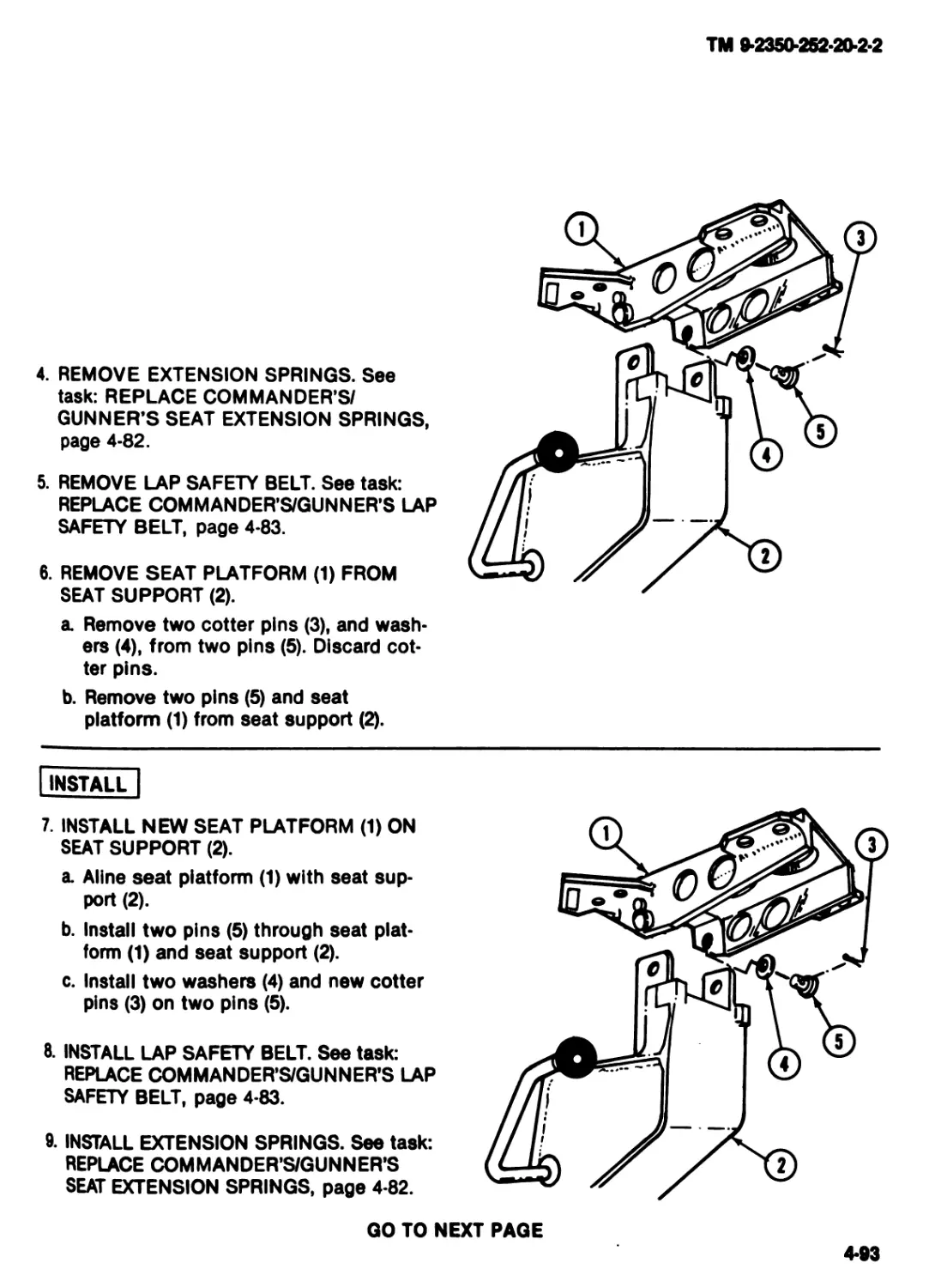
4. REMOVE EXTENSION SPRINGS. See
task: REPLACE COMMANDER’S/
GUNNER’S SEAT EXTENSION SPRINGS,
page 4-82.
5. REMOVE LAP SAFETY BELT. See task:
REPLACE COMMANDER’S/GUNNER’S LAP
SAFETY BELT, page 4-83.
6. REMOVE SEAT PLATFORM (1) FROM
SEAT SUPPORT (2).
a. Remove two cotter pins (3), and wash-
ers (4), from two pins (5). Discard cot-
ter pins.
b. Remove two pins (5) and seat
platform (1) from seat support (2).
INSTALL
7. INSTALL NEW SEAT PLATFORM (1) ON
SEAT SUPPORT (2).
a. Aline seat platform (1) with seat sup-
port (2).
b. Install two pins (5) through seat plat-
form (1) and seat support (2).
c. Install two washers (4) and new cotter
pins (3) on two pins (5).
8. INSTALL LAP SAFETY BELT. See task:
REPLACE COMMANDER’S/GUNNER’S LAP
SAFETY BELT, page 4-83.
9. INSTALL EXTENSION SPRINGS. See task:
REPLACE COMMANDER’S/GUNNER’S
SEAT EXTENSION SPRINGS, page 4-82.
GO TO NEXT PAGE
4-93
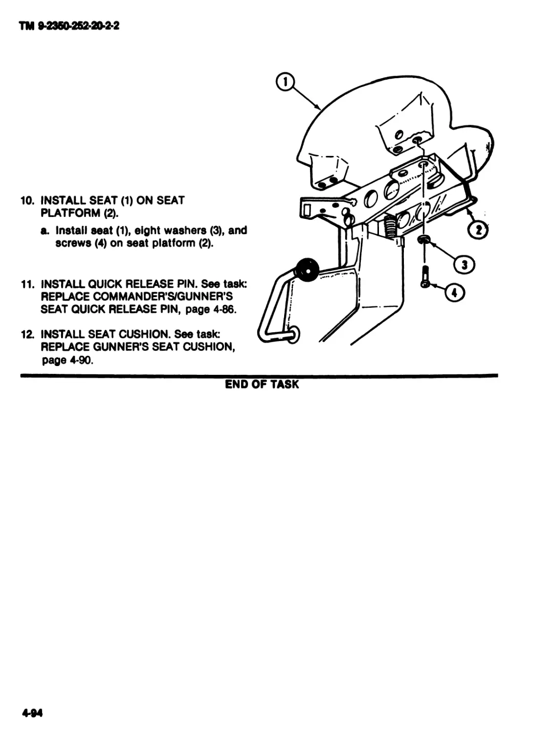
TM 9-2360-252-20-2-2
10. INSTALL SEAT (1) ON SEAT
PLATFORM (2).
a. Install seat (1), eight washers (3), and
screws (4) on seat platform (2).
11. INSTALL QUICK RELEASE PIN. See task:
REPLACE COMMANDER’S/GUNNER’S
SEAT QUICK RELEASE PIN, page 4-86.
12. INSTALL SEAT CUSHION. See task:
REPLACE GUNNER’S SEAT CUSHION,
page 4-90.
END OF TASK
4-94
TM 9*2350*252*20*2*2
CHAPTERS
MAINTENANCE OF TURRET ELECTRICAL SYSTEM
Section I. MAINTENANCE OF EMERGENCY BATTERY ASSEMBLIES
TASK INDEX
Task Page Task Page
Repair Turret Emergency Battery Repair Turret Emergency Battery
Tray, Retainer, and Hook Bolts.5*2 Terminal Lug...........5*7
5*1
TM 9*2350*252*20*2*2
REPAIR TURRET EMERGENCY BATTERY TRAY, RETAINER, AND
HOOK BOLTS
INITIAL SETUP
Tools:
Turret mechanic’s tool kit (Item 31,
Materials/Parts:
Self-locking nut (2)
Personnel Required:
ITV/IFV/CFV Trt Meeh 45T10
App F)
References:
TM 9*2350*252*10*1
TM 9-2350-252*10-2
TM 9-6140-200-14
Equipment Conditions:
Engine stopped (TM 9-2350-252-10-1)
Turret shut down (TM 9-2350-252-10-2)
REPAIR
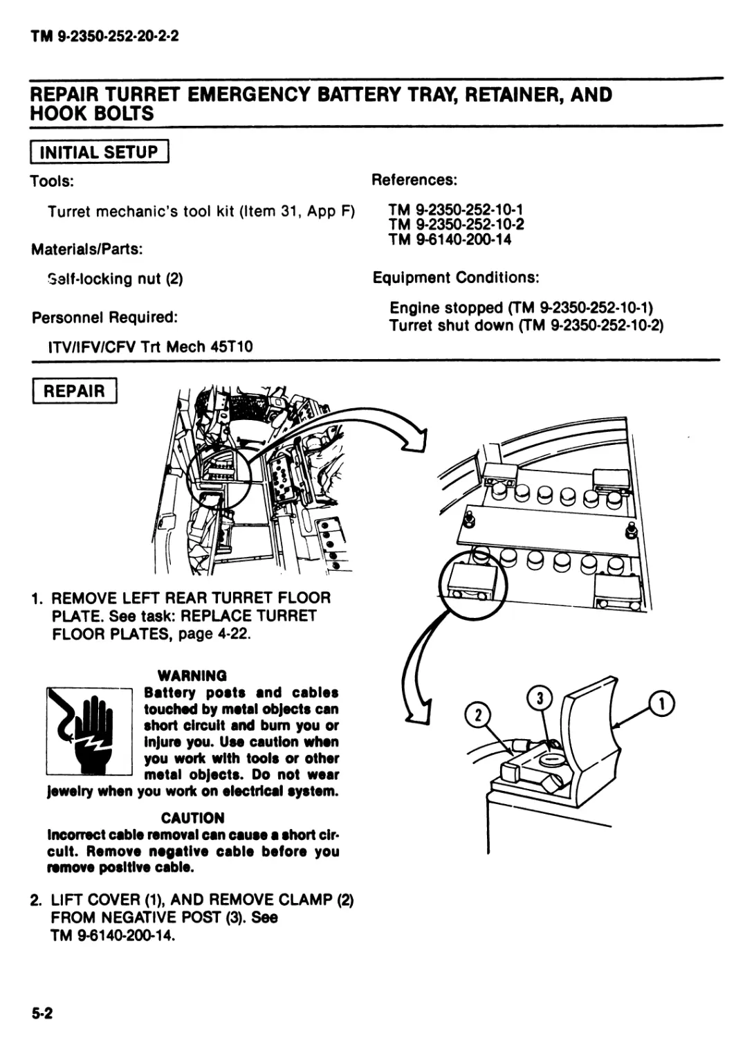
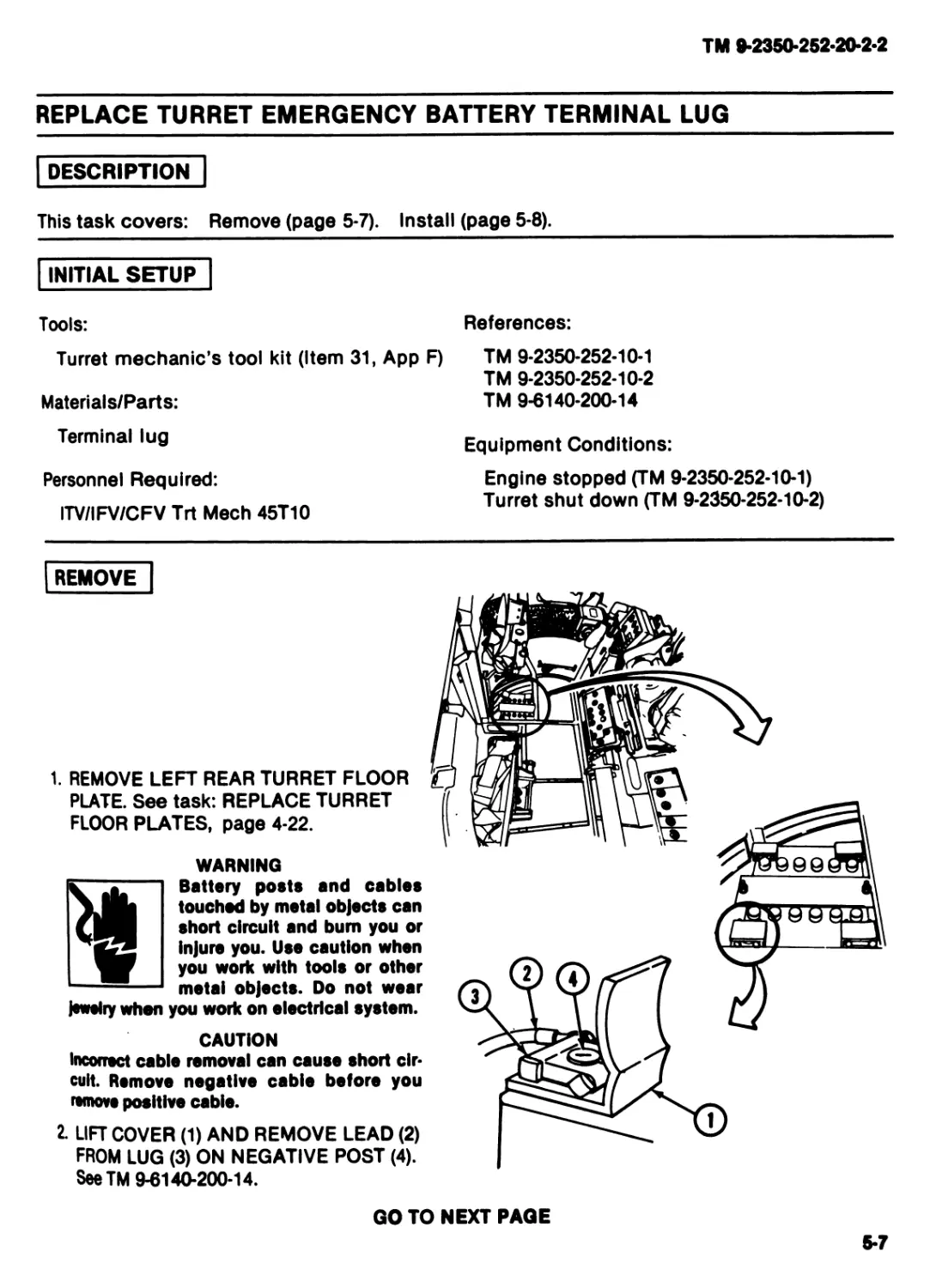
1. REMOVE LEFT REAR TURRET FLOOR
PLATE. See task: REPLACE TURRET
FLOOR PLATES, page 4-22.
>Jil
WARNING
Battery posts and cables
touched by metal objects can
short circuit and bum you or
injure you. Use caution when
you work with tools or other
metal objects. Do not wear
jewelry when you work on electrical system.
CAUTION
Incorrect cable removal can cause a short cir-
cuit. Remove negative cable before you
remove positive cable.
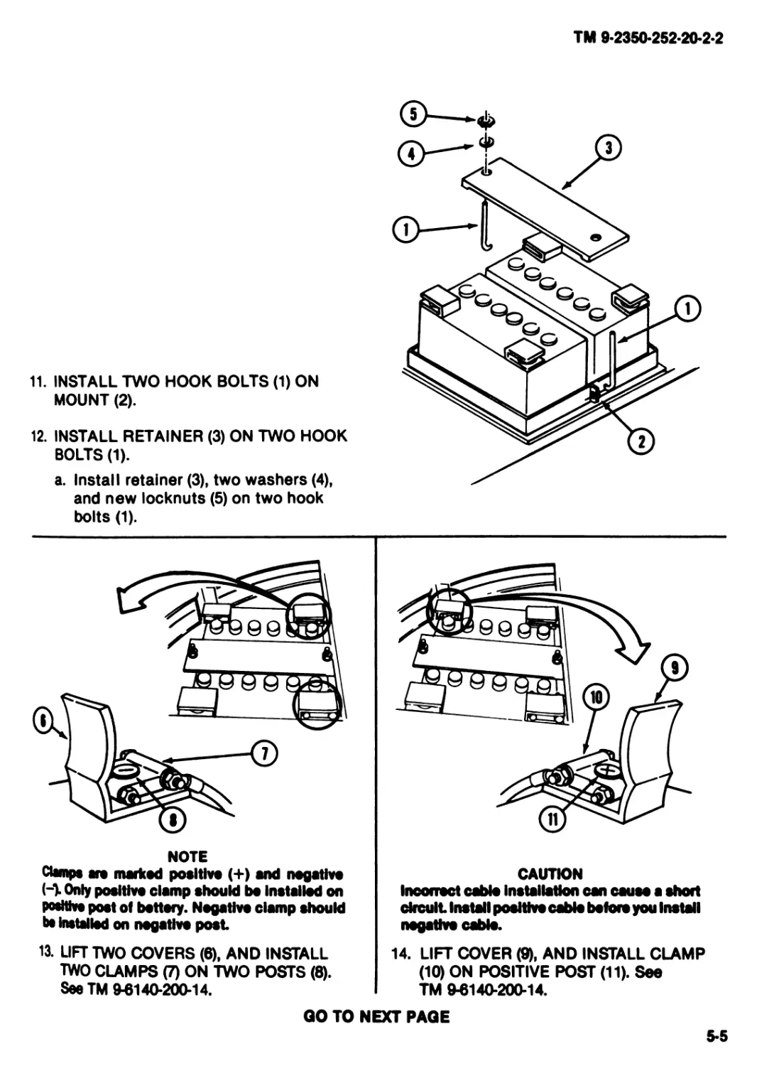
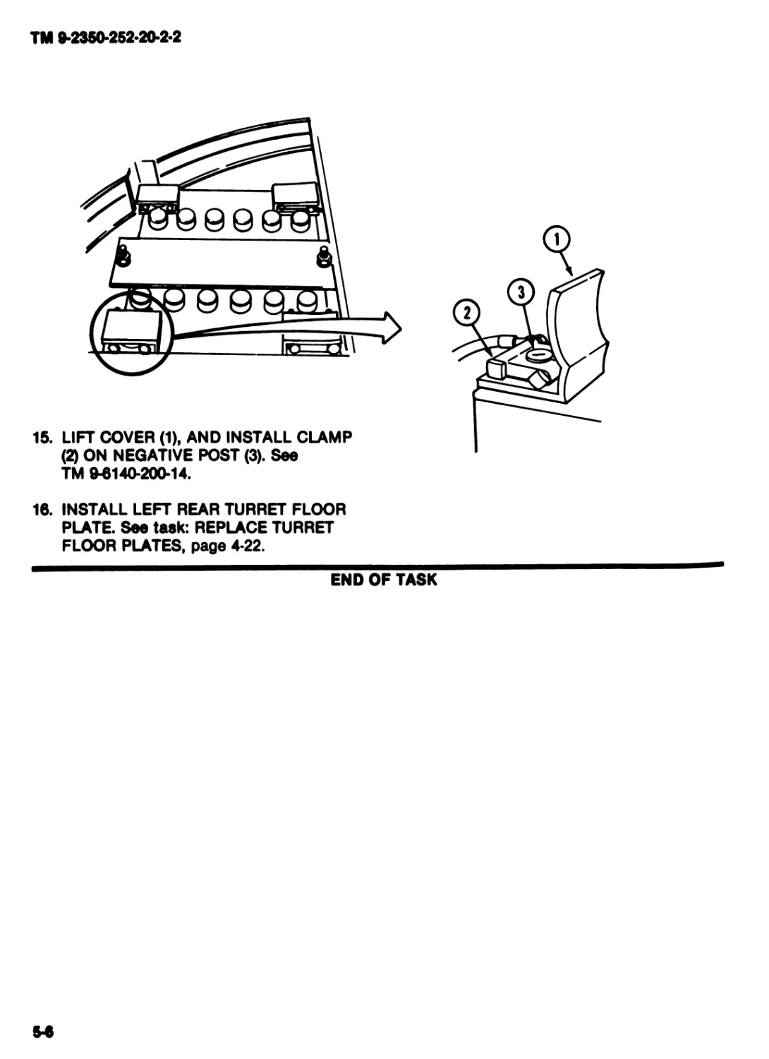
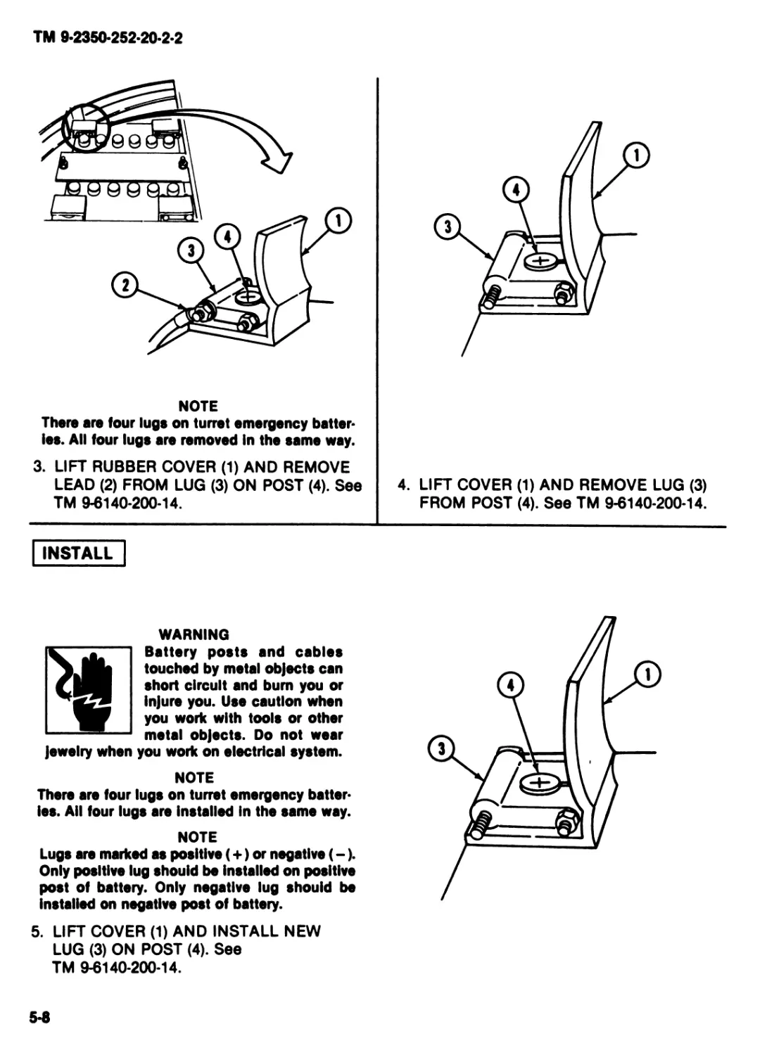
2. LIFT COVER (1), AND REMOVE CLAMP (2)
FROM NEGATIVE POST (3). See
TM 9-6140-200-14.
5-2
TM 9-2350-252-20-2*2
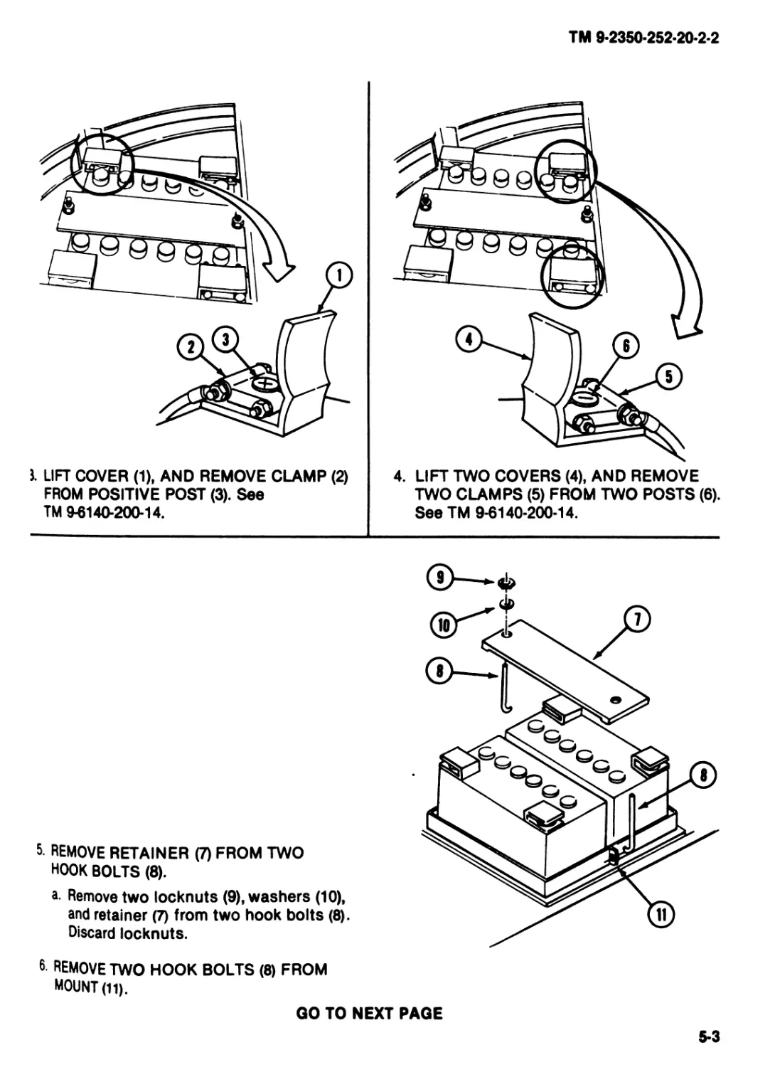
J. LIFT COVER (1), AND REMOVE CLAMP (2)
FROM POSITIVE POST (3). See
TM 9-6140-200-14.
4. LIFT TWO COVERS (4), AND REMOVE
TWO CLAMPS (5) FROM TWO POSTS (6).
See TM 9-6140-200-14.
5. REMOVE RETAINER (7) FROM TWO
HOOK BOLTS (8).
a. Remove two locknuts (9), washers (10),
and retainer (7) from two hook bolts (8).
Discard locknuts.
6 REMOVE TWO HOOK BOLTS (8) FROM
MOUNT (11).
QO TO NEXT PAGE
5-3
TM 9-2350-252-20-2-2
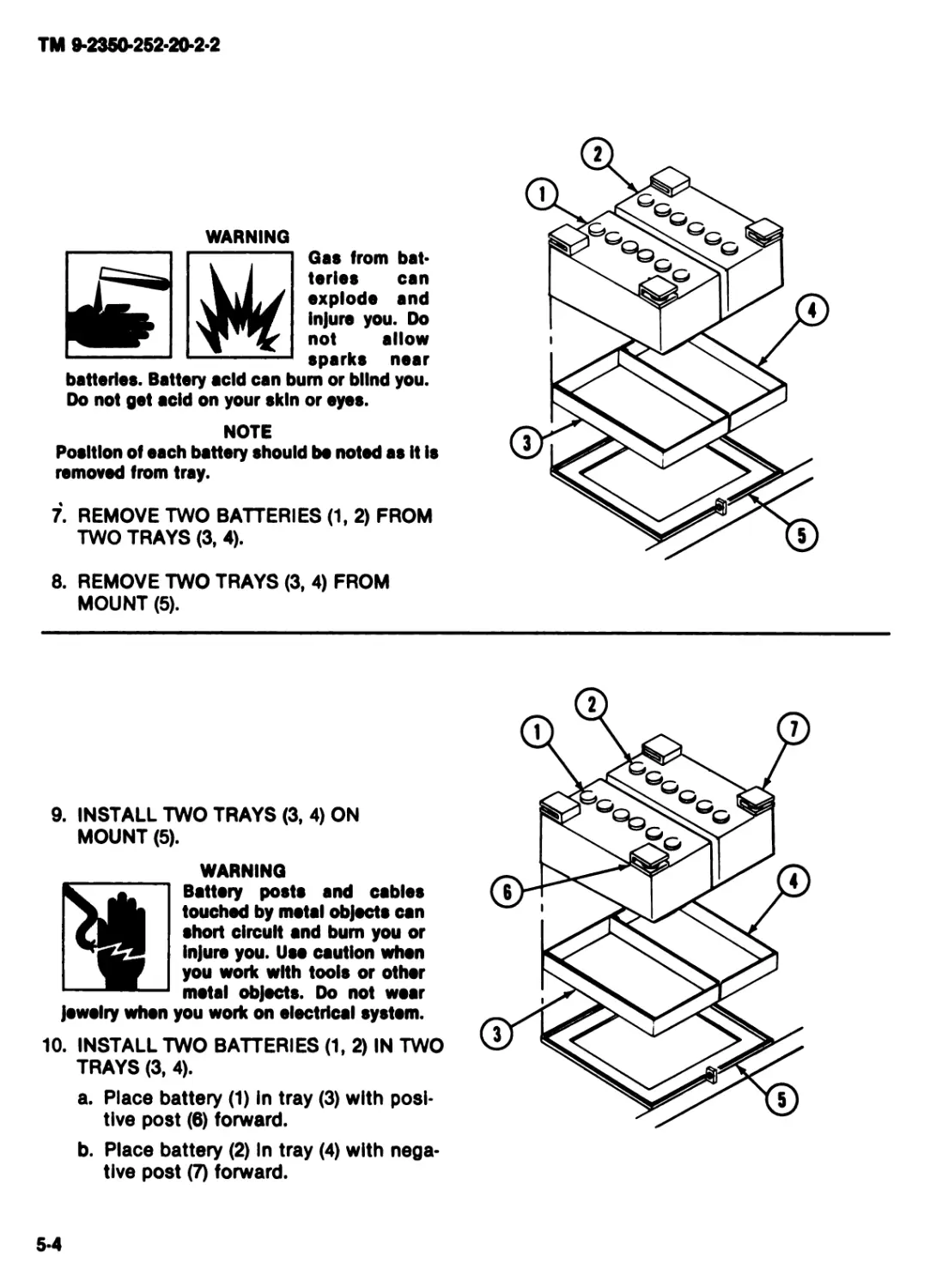
WARNING
Gas from bat-
teries can
explode and
Injure you. Do
not allow
sparks near
batteries. Battery acid can bum or blind you.
Do not get acid on your skin or eyes.
NOTE
Position of each battery should be noted as It Is
removed from tray.
7. REMOVE TWO BATTERIES (1, 2) FROM
TWO TRAYS (3, 4).
8. REMOVE TWO TRAYS (3, 4) FROM
MOUNT (5).
9. INSTALL TWO TRAYS (3, 4) ON
MOUNT (5).
WARNING
Battery posts and cables
touched by metal objects can
short circuit and bum you or
Injure you. Use caution when
you work with tools or other
metal objects. Do not wear
Jewelry when you work on electrical system.
10. INSTALL TWO BATTERIES (1, 2) IN TWO
TRAYS (3, 4).
a. Place battery (1) In tray (3) with posi-
tive post (6) forward.
b. Place battery (2) In tray (4) with nega-
tive post (7) forward.
5-4
TM 9-2350-252-20-2-2
11. INSTALL TWO HOOK BOLTS (1) ON
MOUNT (2).
12. INSTALL RETAINER (3) ON TWO HOOK
BOLTS (1).
a. Install retainer (3), two washers (4),
and new locknuts (5) on two hook
bolts (1).
NOTE
damps are marked positive (+) and negative
(-). Only positive clamp should bo Installed on
podtivo post of bettory. Negative clamp should
bs Installed on negative post
13. LIFT TWO COVERS (6), AND INSTALL
TWO CLAMPS (7) ON TWO POSTS (8).
See TM 9-6140-200-14.
CAUTION
Incorrect cable Installation can cause a short
circuit Install positive cable before you Install
negative cable.
14. LIFT COVER (ty, AND INSTALL CLAMP
(10) ON POSITIVE POST (11). See
TM 9-6140-200-14.
GO TO NEXT PAGE
5-5
TM 9-2350-252-20-2-2
15. LIFT COVER (1). AND INSTALL CLAMP
(2) ON NEGATIVE POST (3). See
TM 9-6140-200-14.
15. INSTALL LEFT REAR TURRET FLOOR
PLATE. See task: REPLACE TURRET
FLOOR PLATES, page 4-22.
END OF TASK
TM 9-2350-252-20-2-2
REPLACE TURRET EMERGENCY BATTERY TERMINAL LUG
DESCRIPTION
This task covers: Remove (page 5*7). Install (page 5-8).
INITIAL SETUP
Tools: References:
Turret mechanic's tool kit (Item 31, App F) TM 9-2350-252-10-1 TM 9-2350-252-10-2
Materials/Parts: TM 9-6140-200-14
Terminal lug Equipment Conditions:
Personnel Required: Engine stopped (TM 9-2350-252-10-1)
ITV/IFV/CFV Trt Meeh 45T10 Turret shut down (TM 9-2350-252-10-2)
REMOVE
jewelry when
1. REMOVE LEFT REAR TURRET FLOOR
PLATE. See task: REPLACE TURRET
FLOOR PLATES, page 4-22.
WARNING
Battery posts and cables
touched by metal objects can
short circuit and bum you or
Injure you. Use caution when
you work with tools or other
metal objects. Do not wear
you work on electrical system.
CAUTION
Incorrect cable removal can cause short cir-
cuit. Remove negative cable before you
remove positive cable.
2. LIFT COVER (1) AND REMOVE LEAD (2)
FROM LUG (3) ON NEGATIVE POST (4).
SeeTM 9-6140-200-14.
GO TO NEXT PAGE
5-7
TM 9-2350*252-20-2-2
NOTE
There are four lugs on turret emergency batter*
ies. All four luge are removed In the same way.
3. LIFT RUBBER COVER (1) AND REMOVE
LEAD (2) FROM LUG (3) ON POST (4). See
TM 9-6140-200-14.
4. LIFT COVER (1) AND REMOVE LUG (3)
FROM POST (4). See TM 9-6140-200-14.
INSTALL
WARNING
Battery posts and cables
touched by metal objects can
short circuit and bum you or
injure you. Use caution when
you work with tools or other
metal objects. Do not wear
jewelry when you work on electrical system.
NOTE
There are four lugs on turret emergency batter-
ies. All four lugs are Installed In the same way.
NOTE
Lugs are marked as positive (+) or negative (-).
Only positive lug should be Installed on positive
post of battery. Only negative lug should be
Installed on negative post of battery.
5. LIFT COVER (1) AND INSTALL NEW
LUG (3) ON POST (4). See
TM 9-6140-200-14.
5-S
TM 9-2350-252-20-2-2
CAUTION
Incorrect cable Installation can cause short
circuit. Install positive cable before you
Install negative cable.
6. LIFT COVER (1) AND INSTALL LEAD (2)
ON LUG (3). See TM 9-6140*200-14.
7. LIFT COVER (4) AND INSTALL LEAD (5)
ON LUG (6) ON NEGATIVE POST (7). See
TM 9-6140-200-14.
8. RETURN TO ORIGINAL SYMPTOM. VER-
IFY NO FAULT.
9. INSTALL LEFT REAR TURRET FLOOR
PLATE. See task: REPLACE TURRET
FLOOR PLATES, page 4-22.
END OF TASK
5-9 (5-10 blank)
TM 9-2350-252-20-2-2
________Section II. MAINTENANCE OF WIRING HARNESSES
TASK INDEX
Task Page
Replace Cable 2W14............5-12
Replace Cable 2W15............5-14
Replace Cable 2W7.............5-17
Replace Cable 2W301...........5-18
Replace Wiring Harness 2W302 . 5-26
Replace Wiring Harness 2W303 . 5-39
Task Page
Replace Cable 2W304 ............. 5-52
Replace Cable 2W305 ............. 5-59
Replace Cable 2W306 ............. 5-63
Replace Wiring Harness 2W307 ...... 5-76
Replace Cable 2W308 ............. 5-83
Replace Cable 2W309 ............. 5-89
511
TM 9-2350-252-20-2-2
REPLACE CABLE 2W14
I DESCRIPTION
This task covers: Remove (page 5-12). Install (page 5-13).
INITIAL SETUP
Tools:
Turret mechanic's tool kit (Item 31, App F)
Materials/Parts:
Special electrical cable assembly
Nylon strap
Personnel Required:
ITV/IFV/CFV Trt Meeh 45T10
References:
TM 9-2350-252-10-1
TM 9-235O252-1O2
TM 0614020014
Equipment Conditions:
Engine stopped (TM 02350-252-10-1)
Turret shut down (TM 02350-252-102)
REMOVE
1. REMOVE LEFT REAR TURRET FLOOR
PLATE. See task: REPLACE TURRET
FLOOR PLATES, page 4-22.
WARNING
Battery posts and cables
touched by metal objects can
short circuit and bum you or
Injure you. Use caution when
you work with tools or other
metal objects. Do not wear
jswslry when you work on
electrical system.
CAUTION
Incorrect cable removal can cause short cir-
cuit. Rsmovs negative cable before you
remove positive cable.
2. LIFT COVER (1) AND REMOVE LEAD (2)
FROM CLAMP (3) ON NEGATIVE POST (4).
See TM 94)140-200-14.
5-12
TM 9-2350-252-20-2-2
INSTALL
WARNING
Battery posts and cables
touched by metal objects can
short circuit and bum you or
Injure you. Use caution when
you work with tools or other
metal objects. Do not wear
Jewelry when you work on electrical system.
REMOVE STRAP (1) FROM CABLE
2W14 <2). DISCARD STRAP.
NOTE
able 2W14 is.removod from both clamps in tho
мм way.
UFT COVERS (3) AND REMOVE CABLE
2W14 (2) FROM TWO CLAMPS (4). See
TM 94149-200-14. DISCARD CABLE.
CAUTION
Incorrect cable Inetallatlon can cauee short
circuit. Install positive cable before you
Install negative cable.
NOTE
Cable 2W14 le Installed on both clampe In the
same way.
5. LIFT COVERS (3) AND INSTALL NEW
CABLE 2W14 (2) ON TWO CLAMPS (4).
SeeTM 94140-200-14.
INSTALL NEW STRAP (1) ON CABLE
2W14 (2).
UFT COVER (5) AND INSTALL LEAD (2)
ON CLAMP (7) ON NEGATIVE POST (8).
SeeTM 94140-200-14.
I return to original symptom.
VERIFY NO FAULT.
I INSTALL LEFT REAR TURRET FLOOR
PLATES. See task: REPLACE TURRET
FLOOR PLATES, page 4-22.
END OF TASK
5-13
TM 9-2350-252-20-2-2
REPLACE CABLE 2W15
DESCRIPTION
This task covers: Remove (page 5*14). Install (page 5*15).
INITIAL SETUP
Tools:
References:
Turret mechanic's tool kit (Item 31, App F)
Materials/Parts:
Self-locking nut
Self-locking nut
Special cable assembly
Personnel Required:
ITV/IFV/CFV Trt Meeh 45T10
TM 9-2350-252-10-1
TM 9-2350-252-10-2
TM 9-6140-200-14
Equipment Conditions:
Engine stopped (TM 9-2350-252-10-1)
Turret shut down (TM 9-2350-252-10-2)
REMOVE
1. REMOVE TURRET STEP AND LEFT REAR
FLOOR PLATES. See task: REPLACE
TURRET FLOOR PLATES, page 4-22.
WARNING
Battery poets and cables
touched by metal objects can
short circuit and bum you or
injure you. Use caution when
working with tools or other
mstal objects. Do not wear
jewelry when you work on electrical system.
CAUTION
Incorrect cable removal can cause short
circuit Remove negative cable before you
remove positive cable.
2. REMOVE CABLE 2W15 (1) FROM
SCREW (2).
a. Remove locknut (3), washer (4), and
cable 2W15 (1) from screw (2). Discard
locknut.
5-14
TM 9-2350-252-20-2-2
REMOVE CABLE 2W15 (1) FROM TWO
CLAMPS (2, 3).
a. Remove screw (4) and clamp (2) from
weldout (5) on turret.
b. Remove locknut (6), screw (7), and
clamp (3) from turret. Discard locknut.
c. Remove cable 2W15 (1) from two
clamps (2, 3).
4. REMOVE CABLE 2W15 (1) FROM
CLAMP (8).
a. Lift cover (9) and remove nut (10) and
cable 2W15 (1) from clamp (8).
WARNING
Battery posts and cables
touched by metal objects can
short circuit and bum you or
Injure you. Use caution when
working with tools or other
metal objects. Do not wear
jewelry when you work on electrical system.
5. INSTALL CABLE 2W15 (1) ON CLAMP (8).
a. Lift cover (9) and install cable 2W15 (1)
and nut (10) on clamp (8).
GO TO NEXT PAGE
5*15
ТМ 9-2350-252-20-2-2
6. INSTALL CABLE 2W15 (1) ON SCREW (2).
a. Install cable 2W15 (1), washer (3), and
new locknut (4) on screw (2).
7. INSTALL CABLE 2W15 (1) IN TWO
CLAMPS (5, 6).
a. Install cable 2W15 (1) in two clamps
(5,6).
b. Install clamp (5) and screw (7) on
weldnut (8) on turret.
c. Install ciamp (6), screw (9), and new
locknut (10) on turret.
8. RETURN TO ORIGINAL SYMPTOM.
VERIFY NO FAULT.
9. INSTALL TURRET LEFT REAR AND
STEP FLOOR PLATES. See task:
REPLACE TURRET FLOOR PLATES,
page 4-22.
END OF TASK
5-18
TM 9-2350-252-20-2-2
REPLACE CABLE 2W7
INITIAL SETUP
ools:
Personnel Required:
Turret mechanic’s tool kit (Item 31, App F) ITV/IFV/CFV Trt Meeh 45T10
Materials/Parts:
Self-locking nut
Cable assembly
Sealing compound, grade A
(Item 20, Арр C)
Primer, grade N (Item 21, Арр C)
References:
TM 9-2350-252-10-1
TM 9-2350-252-10-2
Equipment Conditions:
Engine stopped (TM 9-2350-252-10-1)
Turret shut down (TM 9-2350-252-10-2)
REMOVE
1. REMOVE LEFT FRONT AND CENTER
TURRET FLOOR PLATES. See task:
REPLACE TURRET FLOOR PLATES,
page 4-22.-
2. REMOVE CABLE 2W7 (1) FROM TURRET.
a. Remove locknut (2), screw (3), washer
(4), and cable 2W7 (1) from turret. Dis-
card locknut.
b. Remove screw (5), washer (6), and
cable 2W7 (1) from bracket (7).
INSTALL
3. INSTALL NEW CABLE 2W7 (1) IN
TURRET.
a. Apply primer to threads of screw (5).
b. Apply sealing compound to threads of
screw (5).
c. Install cable 2W7 (1), washer (6), and
screw (5) on bracket (7) finger tight.
d. Install cable 2W7 (1), washer (4), screw
(3), and new locknut (2) on turret finger
tight.
e. Tighten screw (3).
4. TORQUE SCREW (5) to 73-79 IN-LB
(84-91 CM KG).
5. INSTALL LEFT FRONT AND CENTER
TURRET FLOOR PLATES. See task:
REPLACE TURRET FLOOR PLATES,
page 4-22.
END OF TASK
5-17
ТМ 9-2350-252-20-2-2
REPLACE CABLE 2W301
I description]
This task covers: Remove (page 5-18). Install (page 5-22).
[INITIAL SETUP]
Tools: References:
Turret mechanic's tool kit (Item 31, App F) TM 9-2350-252-10*1
TM 9-2350-252-10-2
Materials/Parts:
, Equipment Conditions:
Special cable assembly
Nylon strap (2) Engine stopped (TM 9-2350-252-10-1)
Turret shut down (TM 9-2350-252-10-2)
Personnel Required:
ITV/IFV/CFV Trt Meeh 45T10 "
| REMOVE
1. REMOVE CENTER AND RIGHT TURRET
FLOOR PLATES. See task: REPLACE
TURRET FLOOR PLATES, page 4-22.
2. REMOVE DISTRIBUTION BOX. See task:
REPLACE DISTRIBUTION BOX,
page 5-105.
5-18
TM 9*2350*252*20*2*2
3. REMOVE CABLE 2W301 (1) FROM FOUR
CLAMPS (2).
a. Remove four screws (3) and clamps (2)
from weldnuts (4) on turret.
b. Remove cable 2W301 (1) from four
clamps (2).
5. REMOVE PLUG 2W301P1 (5) FROM JACK
2A200J1 (6).
GO TO NEXT PAGE
5*19
TM 0-2350-252-20-2-2
6. PUSH PLUG 2W301P1 (1) BEHIND
EQUILIBRATOR (2).
CAN (4).
a. Turn latch (5) and lift door (3) up and
out of HE ammo can (4).
5-20
TM 9-2350-252-20-2*2
(4) from HE ammo can (2) and cable
hanger (1).
b. Remove three screws (5), washers (6),
and c?ble hanger (1) from HE ammo
can (2).
(7) FROM
10. PULL P
BETWEEN CABLE HANGER (1) AND HE
AMMO CAN (2).
GO TO NEXT RAGE
5-21
TM 9-2350-252-20-2-2
11. REMOVE TWO STRAPS (1) FROM
CABLES (2). DISCARD STRAPS.
12. REMOVE CABLE 2W301 (3) FROM TWO
CLAM IPS (4).
a. Remove two screws (5) and clamps
(4) from weldnuts (6) on turret.
b. Remove cable 2W301 (3) from two
clamps (4) and turret.
INSTALL
13. PUSH PLUG 2W301P4 (7) OF NEW
CABLE 2W301 (3) BETWEEN CABLE
HANGER (8) AND HE AMMO CAN (9).
5*22
TM 9*2350*252*20*2*2
14. ROUTE PLUG 2W301P1 (1) BEHIND
PLUG 2W308P9 (2) AND BEHIND
EQUILIBRATOR (3).
I--------------------------------------------------------------------------
CAUTION
Cable can be damaged If cable does not go
through notch In cable hangar. Route cable
through notch In cable hanger.
15. INSTALL CABLE HANGER (4) ON HE
AMMO CAN (5).
Route cable 2A22 (8) through notch
(7) in cable hanger (4).
Install cable hanger (4), two washers
(8), and screws (9) on HE ammo
can (5).
a.
b.
c. Install three washers (10) and screws
(11) in HE ammo can (5) and cable
hanger (4).
GO TO NEXT RAGE
5*23
TM 9-2350-252-20-2-2
16. INSTALL DOOR (1) ON HE AMMO
CAN (2).
a. Position bottom of door (1) In door
hanger (3).
b. Close door (1) and turn latch (4) up.
17. MANUALLY TRAVERSE TURRET TO
3000 MILS. See TM 9-2350-252-10-2.
18. INSTALL PLUG 2W301P1 (5) ON JACK
2A200J1 (6).
544
TM 9-2350-252-20-2-2
1.
INSTALL TWO NEW STRAPS (5) ON
CABLES (6).
LLY TRAVERSE TURRET TO
6400 MILS. See TM 9-2350-252-10-2.
MANUALLY TRAVERSE TURRET TO
2400 MILS. See TM 9-2350-252-10-2.
INSTALL CABLE 2W301 (1) IN TWO
CLAMPS (2).
a. Install cable 2W301 (1) In two
clamps (2).
b. Install two clamps (2) and screws (3)
on weldnuts (4) on turret.
23. INSTALL CABLE 2W301 (1) IN FOUR
CLAMPS (7).
a. Install cable 2W301 (1) in four
clamps (7).
b. Install four clamps (7) and screws (8)
on weldnuts (9) on turret.
24. INSTALL DISTRIBUTION BOX. See task:
REPLACE DISTRIBUTION BOX,
page 5-105.
25. INSTALL RIGHT AND CENTER TURRET
FLOOR PLATES. See task: REPLACE
TURRET FLOOR PLATES, page 4-22.
28. RETURN TO ORIGINAL SYMPTOM. VER-
IFY NO FAULT.
END OF TASK
5-25
TM 9-2350-252-20-2-2
REPLACE WIRING HARNESS 2W302
DESCRIPTION
This task covers: Remove (page 5*26). Install (page 5*32).
INITIAL SETUP
Tools: Personnel Required:
Turret mechanic's tool kit (Item 31, App F) ITV/IFV/CFV Trt Meeh 45T10
Materials/Parts:
Nylon strap (2)
Special cable assembly
SelMocking nut
References:
TM 9*2350*252*10*1
TM 9-2350-252-10-2
Equipment Conditions:
Engine stopped (TM 9-2350-252-10-1)
Turret shut down (TM 9-2350-252-10-2)
I REMOVE |
2.
3.
REMOVE ISU. See task: REMOVE/
INSTALL INTEGRATED SIGHT UNIT,
page 21-43.
REMOVE 25MM AP AMMO CHUTE. See
task: REPLACE 25MM AP AMMO CHUTE,
page 26-22.
REMOVE 25MM HE AMMO CHUTE
ASSEMBLY. Seo task: REPLACE 25MM
HE AMMO CHUTE ASSEMBLY,
page 26-26.
REMOVE PLUG 2W302P1 (1) FROM JACK
2A205J1 (2).
5*26
ТМ 9-2350-2Б2-20-2-2
. REMOVE 25MM AMMO GUARD GUN
MOUNT. See task: REPLACE 25MM
AMMO GUARD GUN MOUNT, page 26-4.
v REMOVE LEAD 2W302P1 (1) FROM TWO
CLAMPS (2).
a. Remove two screws (3) and clamps (2)
from weldnuts (4) on turret.
b. Remove lead 2W302P1 (1) from two
clamps (2).
CLAMP (5).
GO TO NEXT PAGE
5-27
TM 9-2350-252-20-2-2
8. REMOVE TWO PLUGS (1) FROM TWO
JACKS (2) ON GUN ELEVATION DRIVE
MOTOR (3) AS FOLLOWS:
2W302P4 FROM 2A202J2
2W302P5 FROM 2A202J3.
TAG PLUGS.
9. REMOVE TWO PLUGS (4) FROM TWO
JACKS (5) ON GUN ELEVATION DRIVE
MOTOR (6) AS FOLLOWS:
2W302P2 FROM 2A203J2
2W302P3 FROM 2A203J3.
TAG PLUGS.
5-28
TM 9*2350*252*20-2*2
10. REMOVE LEADS 2W302P2 (1) AND
2W302P3 (2) FROM FOUR CLAMPS (3).
a Remove four screws (4) and clamps
(3) from weldnuts (5) on turret.
b. Remove leads 2W302P2 (1) and
2W302P3 (2) from four clamps (3).
11. REMOVE PLUG 2W302P6 (6) FROM
JACK 2A206J1 (7).
12. MANUALLY TRAVERSE TURRET TO
3200 MILS. See TM 9-2350*252*10*2.
GO TO NEXT PAGE
5*29
TM 9-2350-252-20-2-2
13. REMOVE PLUG 2W302P7 (1) FROM
JACK 2A200J2 (2).
14. REMOVE TWO STRAPS (3) FROM
TWO CABLES (4). DISCARD STRAPS.
6*30
TM 9-2350-252-20-2-2
a.
b.
c.
15. REMOVE.WIRING HARNESS 2W302 (1)
FROM TWO CLAMPS (2, 3).
Remove screw (4) and clamp (2) from
weldnut (5) on turret.
Remove locknut (6), screw (7), and
clamp (3) from support (8). Discard
locknut.
Remove wiring harness 2W302 (1)
from two clamps (2,3).
16. MANUALLY TRAVERSE TURRET TO
2850 MILS. See TM 9-2350-252-10-2.
17. REMOVE WIRING HARNESS 2W302 (1)
FROM FOUR CLAMPS (9).
a Remove four screws (10) and
clamps (8) from weldnuts (11) on
turret
b Remove wiring harness 2W302 (1)
from four clamps (9).
GO TO NEXT PAGE
5-31
TM 9*2350*252*20*2-2
18. PULL WIRING HARNESS 2W302 (1)
FROM TURRET.
INSTALL
19. MANUALLY TRAVERSE TURRET TO
3200 MILS. See TM 9-2350-252-10*2.
20. INSTALL NEW WIRING HARNESS
2W302 (1) IN TURRET.
a. Push plugs 2W302P1 (2), 2W302P2 (3),
and 2W302P3 (4) of wiring harness
2W302 (1) through turret opening (5).
b. Push plugs 2W302P4 (6) and
2W302P5 (7) up to gun elevation drive
motor (8).
5*32
TM 9*2350*252*20*2*2
I. INSTALL PLUG 2W302P7 (1) ON
JACK 2A200J2 (2).
2- INSTALL PLUG 2W302P6 (3) ON
JACK2A206J1 (4).
GO TO NEXT PAGE
5-33
TIM 9-2350-252-20-2-2
25. INSTALL TWO PLUGS (4) ON TWO
JACKS (5) ON GUN ELEVATION DRIVE
MOTOR (6) AS FOLLOWS:
2W302P4 ON 2A202J2
2W302P5 ON 2A202J3.
23. MANUALLY TRAVERSE TURRET AS
NEEDED TO PULL WIRING HARNESS
2W302 INTO TURRET. See
TM 9-2350-252-10-2.
24. INSTALL TWO PLUGS (1) ON TWO
JACKS (2) ON TOW ELEVATION DRIVE
MOTOR (3) AS FOLLOWS:
2W302P2 ON 2A203J2
2W302P3 ON 2A203J3.
5-34
TM 9-2350-252-20-2-2
2A205J1 (2).
2W302P3 (4) in four clamps (5).
b. Install four clamps (5) and screws (6)
on weldnuts (7) on turret.
GO TO NEXT PAGE
5*35
TM 9-2350-252-20-2-2
28. INSTALL LEAD 2W302P1 (1) IN TWO
CLAMPS (2).
a. Install lead 2W302P1 (1) in two
clamps (2).
b. Install two clamps (2) and screws (3)
on weldnuts (4) on turret.
29. INSTALL LEAD 2W302P1 (1) IN
CLAMP (5).
30. INSTALL 25MM AMMO GUARD GUN
MOUNT. See task: REPLACE 25MM
AMMO GUARD GUN MOUNT, page 26-4.
5-36
TM 9-2350-252-20-2-2
3. MANUALLY TRAVERSE TURRET TO
3200 MILS. See TM 9-2350-252-10-2.
*• INSTALL WIRING HARNESS 2W302 (1)
INTWOCLAMPS (5,6).
harness 2W302 (1) in
Шр1атрв(5,6).
(5) and screw (7) on
weldnut (8) on turret.
c. Install damp (B), ecrew (9), and new
| tocknutflO) on support (11).
)1. MANUALLY TRAVERSE TURRET TO
21)50 MILS. See TM 9-2350-252-10-2.
32. INSTALL WIRING HARNESS 2W302 (1)
IN FOUR CLAMPS (2).
a Install wiring harness 2W302 (1) in
clamps (2).
b. Install four clamps (2) and screws (3)
on weldnuts (4) on turret.
GO TO NEXT PAGE
5-37
TM 9-2350-252-20-2-2
35. INSTALL TWO NEW STRAPS (1) ON
TWO CABLES (2).
36. MANUALLY TRAVERSE TURRET TO
6400 MILS. See TM 9-2350-252-10-2.
37. INSTALL 25MM HE AMMO CHUTE
ASSEMBLY. See task: REPLACE 25MM
HE AMMO CHUTE ASSEMBLY,
page 26-26.
38. INSTALL 25MM AP AMMO CHUTE.
See task: REPLACE 25MM AP
AMMO CHUTE, page 26-22.
39. INSTALL ISU. See task: REMOVE/
INSTALL INTEGRATED SIGHT UNIT,
page 21-43.
40. RETURN TO ORIGINAL SYMPTOM.
VERIFY NO FAULT.
END OF TASK
5-38
TM 9-2350-252-20-2-2
REPLACE WIRING HARNESS 2W303
I description]
This task covers: Remove (page 5*39). Install (page 5-45).
I INITIAL SETUP!
Tools:
References:
Turret mechanic’s tool kit (Item 31, App F) TM 9-2350-252-10-1
TM 9-2350-252-10*2
Materials/Parts:
Special cable assembly
Nylon strap (в)
Equipment Conditions:
Engine stopped (TM 9-2350*252-10-1)
Turret shut down (TM 9-2350-252-10-2)
Personnel Required:
ITV/IFV/CFV Trt Meeh 45T10
| REMOVE |
1. REMOVE 25MM GUN BARREL. See
TM 9-2350-252-10-2.
2. REMOVE 25MM GUN FEEDER. See
TM 9-2350-252-10-2.
3. REMOVE 25MM GUN RECEIVER. See
TM 9-2350-252-10-2.
4. REMOVE PLUG 2W303P4 (1) FROM JACK
2A208J1 (2).
GO TO NEXT PAGE
5*39
TM 9-2350*252-20-2-2
5. REMOVE LEAD 2W303P4 (1) FROM
SEVEN CLAMPS (2).
a. Remove seven screws (3) and
clamps (2) from turret.
b. Remove lead 2W303P4 (1) from seven
clamps (2).
6. REMOVE LEAD 2W303P1 (4) FROM
CLAMP (5).
a. Remove screw (6) and two clamps
(5, 7) from weldnut (8) on turret.
b< Remove lead 2W303P1 (4) from
clamp (5).
5-40
TM 9-2350-252-20-2-2
2W303P4 (4) from clamp (5).
GO TO NEXT PAGE
5-41
TM 9-2350-252-20'2'2
9. REMOVE LEFT, CENTER, AND STEP
TURRET FLOOR PLATES. See task:
REPLACE TURRET FLOOR PLATES,
page 4-22.
10. REMOVE PLUG 2W303P2 (1) FROM
JACK 2A7J7 (2).
clamps (4).
5*42
TM 9*2350-252-20*2*2
2850 MILS. See TM 9-2350-252-10-2.
I3. REMOVE PLUG 2W303P3 (1) FROM
JACK 2A200J3 (2).
14. REMOVlEStX STRAPS (3) FROM TWO
CABLED DISCARD STRAPS.
15. REMOVIE1EAD 2W303P2 (4) FROM TWO
CLAMPS
a. Remove two screws (6) and clamps (5)
from MMdftUtS (7) on turret.
b. Remotelaad2W303P2 (4) from two
clamps (5) on weidnuts (7) on turret.
GO TO NEXT PAGE
5-43
TM 6-2350-252-20-2-2
CAN (2).
a. Tum latch (3) and lift door (1) up and
out of HE ammo can (2).
18. REMOVE CABLE HANGER (4) FROM HE
AMMO CAN (2).
a. Remove two screws (5) and
washers (8) from HE ammo can (2)
and cable hanger (4).
b. Remove three screws (7).
washers (9, and cable hanger (4)
from HE ammo can (2).
6-44
TM 9-2350*252-20-2-2
19. PULL PLUG 2W303P2 (1) FROM
BETWEEN HE AMMO CAN (2) AND
SUPPORT (3).
INSTALL
20. PUSH PLUG 2W303P2 (1) OF NEW WIR-
ING HARNESS 2W303 BETWEEN HE
AMMO CAN (2) AND SUPPORT (3).
GO TO NEXT PAGE
5-45
TM 9-2350-252-20-2-2
CAUTION
Cable can be damaged If cable does not go
through notch In aupport. Route cable
through notch In aupport.
21. INSTALL SUPPORT (1) ON HE AMMO
CAN (2).
a. Route cable 2A22 (3) through
notch (4) In support (1).
b. Install support (1), two washers (5),
and screws (в) on HE ammo can (2).
c. Install three washers (7) and
screws (8) In HE ammo can (2) and
support (1).
23. MANUALLY TRAVERSE TURRET TO
2850 MILS. See TM 9-2350*252*10-2.
5-48
TM 5*2350-252*20>2>2
. INSTALL SIX NEW STRAPS (5) ON
CABLES.
. INSTALL LEAD 2W303P2 (1) IN TWO
CLAMPS (2).
a. Install lead 2W303P2 (1) In two
clamps (2).
b. Install two clamps (2) and two
screws (3) on weldnuts (4) on turret.
8. INSTALL PLUG 2W303P3 (6) ON JACK
2A200J3 (7).
GO TO NEXT PAGE
547
TM 9-2350-252-20-2-2
27. MANUALLY TRAVERSE TURRET TO
6400 MILS. See TM 9-2350*252-10-2.
28. INSTALL LEAD 2W303P2 (1) IN THREE
CLAMPS (2).
a. Install lead 2W303P2 (1) In three
clamps (2).
b. Install three clamps (2) and screws (3)
on weldnuts (4) on turret.
29. INSTALL PLUG 2W303P2 (5) ON JACK
2A7J7 (6).
5-48
TM 0-2360-252-20-2-2
30. INSTALL LEFT, CENTER, AND STEP
TURRET FLOOR PLATES. See task:
REPLACE TURRET FLOOR PLATES,
page'4-22. ,
31. INSTALLLEADS 2W303P1 (1) AND
2W3|3P4.(2) IN CLAMP (3).
a. iiuM leads 2W303P1 (1) and
:2W308P4 (2) In clamp (3).
b. Indt^l cfamp (3) and screw (4) on
wMdnut(5) on turret.
32. INSTALL PLUG 2W303P1 (6) ON JACK
2A207J1 (7).
GO TO NEXT PAGE
5-49
TM 9-2350-252-20-2-2
screws on turret.
5*60
TM 9-2350-262-20-2-2
35.
36.
37.
INSTALL PLUG 2W303P4 (1) ON JACK
2A208J1 (2).
INSTALL 25MM GUN RECEIVER. See
TM 9-2350-252-10-2.
INSTALL 25MM GUN FEEDER. See
TM 9-2350-252-10-2.
38. INSTALL 25MM GUN BARREL. See
TM 9-2350-252-10-2.
39. RETURN TO ORIGINAL SYMPTOM.
VERIFY NO FAULT.
END OF TASK
Ml
TM 9-2350-252-20-2-2
REPLACE CABLE 2W304
DESCRIPTION
This task covers: Remove (page 5-52). Install (page 5-55).
INITIAL SETUP
Tools:
Turret mechanic's tool kit
Materials/Parts:
Nylon strap (3)
Special cable assembly
Personnel Required:
ITV/IFV/CFV Trt Meeh 45T10
References:
TM 9-2350-252-10-1
TM 9-2350-252-10-2
Equipment Conditions:
Engine stopped (TM 9-2350-252-10-1)
Turret shut down (TM 9-2350-252-10-2)
page 21-43.
2. REMOVE 25MM AP AMMO CHUTE. See
task: REPLACE 25MM AP AMMO
CHUTE, page 25-22.
3. REMOVE 25MM HE AMMO CHUTE. See
task: REPLACE 25MM HE AMMO CHUTE
ASSEMBLY, page 25-25.
4. REMOVE 25MM AMMO GUARD GUN
MOUNT. See task: REPLACE 25MM
AMMO GUARD GUN MOUNT, page 25-4.
5. REMOVE PLUG 2W304P1 (1) FROM
JACK 2A203J1 (2).
GO TO NEXT PAGE
5*52
TM 9*2350*252*20*2*2
REMOVE CABLE 2W304 (1) FROM FOUR
CLAMPS (2).
a. Remove four screws (3) and clamps (2)
from weldnuts (4) on turret.
b. Remove cable 2W304 (1) from four
clamps (2).
r REMOVE CABLE 2W304 (1) FROM
CLAMP (5).
* REMOVE CABLE 2W304 (1) FROM
CLAMP (6).
GO TO NEXT PAGE
5*53
TM 9-2350-252-20-2-2
9. MANUALLY TRAVERSE TURRET TO
3500 MILS. See TM 9-2350-252-10-2.
10. REMOVE PLUG 2W30 ',P5 (1) FROM
JACK 2A200J5 (2).
11. REMOVE THREE STRAPS (3) FROM
CABLES. DISCARD STRAPS.
TM 5-2350-252-20-2-2
(2) from weldnuts (4) on turret.
b. Remove cable 2W304 (1) from two
clamps (2).
Й- PULL PLUG 2W304P5 (5) INTO TURRET,
AND REMOVE CABLE 2W304 (1) FROM
TURRET.
GO TO NEXT PAGE
5-66
TM 6-2350-252-20-2-2
INSTALL|
14. PLACE NEW CABLE 2W304 (1) IN TUR-
RET, AND PUSH PLUG 2W304P5 (2) OUT
OF TURRET INTO SQUAD AREA.
15. INSTALL PLUG 2W304P5 (2) ON JACK
2A200J5(3).
16. INSTALL CABLE 2W3Q4 (1) IN TWO
CLAMPS (4).
a. Install cable 2W304 (1) in two
clamps (4).
b. Install two clamps (4) and screws (
on weldnuts (6) on turret.
5*66
TM 9*2350*252*20*2*2
Г. INSTALL THREE NEW STRAPS (1) ON
CABLES.
18. MANUALLY TRAVERSE TURRET TO
6400 MILS. See TM 9-2350*252-10*2.
19. INSTALL PLUG 2W304P1 (2) ON
JACK 2A203J1 (3).
a. Route cable 2W304 (4) to
jack 2A203J1 (3).
b. Install plug 2W304P1 (2) on
jack 2A203J1 (3).
21. INSTALL CABLE 2W304 (4) IN
CLAMP (6).
GO TO NEXT PAGE
5*57
TM 9-2350-252-20-2-2
clamps (2).
b. Install four clamps (2) and screws (3)
on weldnuts (4) on turret.
23. INSTALL 25MM AMMO GUARD GUN
MOUNT. See task: REPLACE 25MM
AMMO GUARD GUN MOUNT, page 26-4.
24. INSTALL 25MM HE AMMO CHUTE. See
task: REPLACE 25MM HE AMMO
CHUTE ASSEMBLY, page 26-26.
25. INSTALL 25MM AP AMMO CHUTE. See
task: REPLACE 25MM AP AMMO
CHUTE, page 26-22.
26. INSTALL ISU. See task: REMOVE/
INSTALL INTEGRATED SIGHT UNIT,
page 21-43.
27. BORESIGHT 25MM GUN. See
TM 9-2350-252-10-2.
END OF TASK
5-56
TM 9*2350*252*20*2*2
REPLACE CABLE 2W305
DESCRIPTION
‘his task covers: Remove (page 5- 59
INITIAL SETUP
Tools:
Turret mechanic’s tool kit (Item 31, App F)
Materials/Parts:
Self-locking nut
Nylon strap (2)
Special cable assembly
’ersonnel Required:
ITV/IFV/CFV Trt Meeh 45T10
Install (page 5-61).
References:
TM 9-2350-252-10*1
TM 9-2350-252-10-2
Equipment Conditions:
Engine stopped (TM 9-2350-252-10-1)
Turret shut down (TM 9-2350-252-10-2)
REMOVE
1. MANUALLY TRAVERSE TURRET TO
3400 MILS. See TM 9-2350-252-10-2.
1 REMOVE PLUG 2W305P1 (1) FROM
JACK 2A202J1 (2).
GO TO NEXT PAGE
5*59
TM 9-2350-252-20-2-2
3. REMOVE TWO STRAPS (1) FROM
CABLES (2). DISCARD STRAPS.
4. REMOVE CABLE 2W305 (3) FROM TWO
CLAMPS (4, 5).
a. Remove locknut (6), screw (7), and
clamp (4) from hanger (8) on turret.
Discard locknut.
b. Remove screw (9) and clamp (5) from
weldnut (10) on turret.
c. Remove cable 2W305 (3) from two
clamps (4, 5).
5-60
TM 9*2350*252-20-2*2
5. REMOVE PLUG 2W305P6 (1) FROM
JACK 2A200J6 (2).
6. PULL CABLE 2W305 (3) FROM TURRET.
7. INSTALL PLUG 2W305P6 (1) OF NEW
CABLE 2W305 (3) ON JACK 2A200J6 (2).
8. PUSH CABLE 2W305 (3) INTO TURRET.
GO TO NEXT PAGE
561
TM 9-2350-252-20-2-2
9. INSTALL CABLE 2W305 (1) IN TWO
CLAMPS (2. 3).
a. Install cable 2W305 (1) In two
clamps (2, 3).
b. Install clamp (2) and screw (4) on
weldnut (5) on turret.
c. Install clamp (3), screw (6), and new
locknut (7) on hanger (8) on turret.
10. INSTALL TWO NEW STRAPS (9) ON
CABLES (10).
11. INSTALL PLUG 2W305P1 (11) ON JACK
2A202J1 (12).
12. MANUALLY TRAVERSE TURRET TO
6400 MILS. See TM 9-2350-252-10-2.
13. RETURN TO ORIGINAL SYMPTOM.
VERIFY NO FAULT.
END OF TASK
5-62
TM 9*2350*252*20*2*2
REPLACE CABLE 2W306
DESCRIPTION
This task covers: Remove (page 5-63). Install (page 5-69).
INITIAL SETUP
Tools:
Turret mechanic's tool kit (Item 31, App F)
Lifting device with rated lift capability of
at least 1002 lb (465 kg)
Nylon sling, 25 ft (Item 9, Арр C)
Materials/Parts:
Sealing compound, grade A
(Item 20, Арр C)
Primer, grade N (Item 21, Арр C)
Cable assembly
Cotter pin
Lock washer (2)
Personnel Required:
ITV/IFV/CFV Trt Meeh 45T10
Helper (H)
References:
TM 9-2350-252-10-1
TM 9-2350-252-10-2
Equipment Conditions:
Engine stopped (TM 9-2350-252-10-1)
Turret shut down (TM 9-2350-252-10-2)
REMOVE
1. REMOVE ISU. See task: REMOVE/
INSTALL INTEGRATED SIGHT UNIT,
page 21-43.
2. REMOVE 25MM AP AMMO CHUTE. See
task: REPLACE 25MM AP AMMO CHUTE,
page 26-22.
3. REMOVE 25MM HE AMMO CHUTE. See
task: REPLACE 25MM HE AMMO CHUTE
ASSEMBLY, page 26-26.
4. REMOVE 25MM AMMO CHUTE GUARD.
See task: REPLACE 25MM AMMO
GUARD GUN MOUNT, page 26-4.
5. MANUALLY TRAVERSE TURRET TO
3600 MILS. See TM 9-2350-252-10-2.
6. MANUALLY RAISE TOW LAUNCHER
TO FIRING POSITION.
See TM 9-2350-252-10-2.
7. REMOVE CABLE 2W306 (1) FROM TWO
CLAMPS (2).
a. Remove two screws (3) and clamps (2)
from weldnuts (4) on turret.
b. Remove cable 2W306 (1) from two
clamps (2).
GO TO NEXT PAGE
5*63
TM 9«2350*252*20*2*2
8. REMOVE PLUG 2W306P7 (1) FROM
JACK 2A200J7 (2) ON ELECTRONIC
CONTROL ASSEMBLY (3).
9. PULL CABLE 2W306 (4) INTO TURRET.
5-64
TM 9-2350-252-20-2-2
10. REMOVE CABLE 2W306 (1) FROM
THREE CLAMPS (2).
a. Remove three screws (3) and
clamps (2) from weldnuts (4) on turret.
b. Remove cable 2W306 (1) from three
clamps (2).
11. MANUALLY TRAVERSE TURRET TO
4800 MILS. See TM 9*2350-252*10-2.
WARNING
Unsupported TOW launcher
can fall and Injure soldiers.
Do not work under unsup-
ported TOW launcher.
12. ATTACH SLINGS (6) TO LAUNCHER (7).
a. Attach slings (6) around launcher (7),
between support bracket (8), upper
bracket (9) and forward electrical
mechanical post (10).
b. Take up slack in slings (6) to
| support launcher (7). Use lifting
' device.
GO TO NEXT PAGE
5-65
TM 9*2350*252*20*2*2
13. REMOVE SHIELD (1) FROM
HOUSING (2).
a. Remove four screws (3) and shield (1)
from housing (2).
14. REMOVE GROUND STRAP (4) FROM
GEARBOX (5).
a. Remove screw (6), two lock
washers (7), and ground strap (4) from
gearbox (5). Discard lock washers.
15. REMOVE TWO PLUGS (8) FROM TWO
JACKS (9) AS FOLLOWS:
3W306P2 FROM J2
3W306P4 FROM J4.
TAG PLUGS.
16. REMOVE PLUG 2W306P3 (10) FROM
JACK 2A200J3(11).
5-66
TM 9-2350-252-20-2 2
a.
NOTE
Step 17 should be done only If gearbox Is
secured to lower bracket with cotter pin,
washer, and pin.
17. REMOVE PIN (1) FROM LOWER
BRACKET (2). HAVE HELPER ASSIST.
(H) Pull manual release knob (3)
and hold out.
Raise and lower ballscrew (4) to
release pressure on pin (1). Use speed
wrench and 14 mm socket at manual
drive input (5).
While holding gearbox (6), remove
cotter pin (7), washer (8), and pin (7).
Discard cotter pin.
b.
c.
NOTE
Step 18 should be done only if gearbox Is
secured to lower bracket with locknut and
screw.
18. REMOVE SCREW (9) FROM LOWER
BRACKET (2). HAVE HELPER ASSIST.
a. (H) Pull manual release knob (3)
and hold out.
b. Raise and lower ballscrew (4) to
release pressure on screw (9). Use
speed wrench and 14 mm socket at
manual drive input (5).
c. While holding gearbox (6), remove
locknut (10) and screw (9). Discard
locknut and screw.
GO TO NEXT PAGE
5-67
TM 9-2350-252-20 2 2
19. (H) PULL OUT ON LOWER END OF
GEARBOX (1).
20. REMOVE PLUG 2W306P1 (2) FROM
JACK 2A200J1 (3).
21. REMOVE CABLE 2W306 (4) FROM
TWO CLAMPS (5).
a. Remove two screws (6),
washers (7), and clamps (5) from
faceplate (8).
b. Remove cable 2W306 (4) from
two clamps (5).
5-68
TM 9-2350*252*20*2*2
22. REMOVE BRACKET (1) FROM
FACEPLATE (2).
a. Remove three screws (3), washers (4),
and bracket (1) from faceplate (2).
23. PULL CABLE 2W306 (5) AND PLUG
2W306P7 (6) OUT OF TURRET
THROUGH FACEPLATE (2).
INSTALL
24. PUSH PLUG 2W306P7 (6) AND NEW
CABLE 2W306 (5) INTO TURRET
THROUGH FACEPLATE (2).
GO TO NEXT PAGE
5-69
TM 9-2350-252-20-2-2
25. INSTALL BRACKET (1) ON
FACEPLATE (2).
a. Apply primer to threads of
three screws (3).
b. Apply sealing compound to
threads of three screws (3).
c. Install bracket (1), three washers (4),
and screws (3) on faceplate (2).
d. TORQUE THREE SCREWS (3)
TO 73-79 IN-LB (84-91 CM KG).
26. INSTALL CABLE 2W306 (5) IN TWO
CLAMPS (6).
a. Install cable 2W306 (5) In two
clamps (6).
b. Install two clamps (6), washers (7),
and screws (8) on faceplate (2).
c. TORQUE TWO SCREWS (8) ON
CLAMPS (6) ON FACEPLATE (2) TO
73-79 IN-LB (84-91 CMKG).
5*70
TM 9*2350*252*20*2*2
27. POSITION GEARBOX (1) TO
FACEPLATE (2).
28. INSTALL PLUG 2W306P1 (3) ON
JACK 2A200J1 (4) ON GEARBOX (1).
NOTE
If screw and locknut were removed in step 7,
they must be replaced by a new pin, washer,
and cotter pin.
29. INSTALL GEARBOX (1) ON LOWER
BRACKET (2).
a. Turn manual drive shaft (3), and
pull manual release knob (4)
to aline gearbox (1) and lower
bracket (2).
b. Install gearbox (1), pin (5),
washer (6), and new cotter
pin (7) on lower bracket (2).
30. INSTALL PLUG 2W306P3 (8) ON
JACK 2A200J3 (9).
31. INSTALL TWO PLUGS (10) ON TWO
JACKS (11) AS FOLLOWS:
3W306P4 ON J4
3W306P2 ON J2.
GO TO NEXT PAGE
5*71
TM 9*2350*252*20*2*2
32. INSTALL GROUND STRAP (1) ON
GEARBOX (2).
a. Install ground strap (1), two new lock
washers (3), and screws (4) on
gearbox (2).
33. INSTALL SHIELD (5) ON HOUSING (6).
a. Apply primer to threads of four
screws (7).
b. Apply sealing compound to threads
of four screws (7).
c. Install shield (5) and four
screws (7) on housing (6).
34. REMOVE SLINGS (8) FROM
LAUNCHER (9).
5-72
TM 9*2350*252*20-2*2
a.
b.
35. PULL CABLE 2W306 (1) INTO TURRET.
Pull cable 2W306 (1) through
rotor (2) into turret.
Loop cable 2W306 (1) to right
side of rotor (2).
c. Pull cable 2W306 (1) over rear
spoke of mount (3) into turret.
36. INSTALL CABLE 2W306 (1) IN
THREE CLAMPS (4).
a. Apply primer to threads of three
screws (5).
b. Apply sealing compound to threads
of three screws (5).
c. Install cable 2W306 (1) In three
clamps (4).
d. Install three clamps (4) and screws (5)
on weldnuts (6) on turret.
GO TO NEXT PAGE
5-73
TM 9*2350*252*20*2*2
37. MANUALLY TRAVERSE TURRET
TO 3600 MILS. See TM 9-2350-252-10-2.
38. PUSH CABLE 2W306 (1) OUT OF
TURRET INTO SQUAD AREA.
39. INSTALL PLUG 2W306P7 (2) ON
JACK 2A200J7 (3) ON ELECTRONIC
CONTROL ASSEMBLY (4).
5*74
TM 9-2350-252-20-2-2
TWO CLAMPS (2).
a. Install cable 2W306 (1) in two
clamps (2).
44. INSTALL 25MM AMMO GUARD GUN
MOUNT. See task: REPLACE 25MM
AMMp GUARD GUN MOUNT, page 26-4.
b. Install two clamps (2) and screws (3)
on weldnuts (4) on turret.
45. INSTALL 25MM HE AMMO CHUTE. See
task: REPLACE 25MM HE AMMO
41. CHECK OPERATION OF TOW
LAUNCHER. SeeTM 9-2350-252-10-2.
42. MANUALLY LOWER TOW
LAUNCHER TO STOWED POSITION.
SeeTM 9-2350-252-10-2.
43. MANUALY TRAVERSE TURRET
TO 6400 MILS. See TM 9-2350-252-10-2.
CHUTE ASSEMBLY, page 26-26.
46. INSTALL 25MM AP AMMO CHUTE. See
task: REPLACE 25MM AP AMMO
CHUTE, page 26-22.
47. INSTALL ISU. See task: REMOVE/
INSTALL INTEGRATED SIGHT UNIT,
page 21-43.
END OF TASK
5-75
TM 9-2350-252-20-2-2
REPLACE WIRING HARNESS 2W307
description"
This task covers: Remove (page 5-76). Install (page 5*79).
| INITIAL SETUP
Tools: References:
Turret mechanic’s tool kit (Item 31, App F) TM 9-2350-252*10-1
TM 9-2350-252-10-2
Materials/Parts:
Nylon .trap (2) Equipment Conditions:
Special cable assembly Engine stopped (TM 9-2350-252-10-1)
Turret shut down (TM 9-2350-252-10-2)
Personnel Required:
ITV/IFV/CFV Trt Meeh 45T10
REMOVE
1. REMOVE ISU. See task: REMOVE/
INSTALL INTEGRATED SIGHT UNIT,
page 21-43.
WARNING
Accidental firing of 25mm gun
could kill or Injure soldiers.
Jack rotation could allow
25mm gun to firs. Do not turn
switch jack J1 when you
remove plug from gearbox.
2. REMOVE PLUG 2W307P1 (1) FROM
JACK2A201J1 (2).
3. REMOVE STRAP (3) FROM LEAD
2W307P1 (4) AND TURRET BASKET (5).
DISCARD STRAP.
4. REMOVE PLUG 2W307P2 (6) FROM JACK
2A201J2 (7).
5-75
TM 9-2350-252-20-2-2
5. REMOVE PLUG 2W307P3 (1) FROM JACK
2A201J3 (2).
GO TO NEXT PAGE
5-77
TM 9-2350-252-20-2-2
7. REMOVE 25MM AP AMMO CHUTE. See
task: REPLACE 25MM AP AMMO
CHUTE, page 26-22.
8. REMOVE 25MM HE AMMO CHUTE. See
task: REPLACE 25MM HE AMMO CHUTE
ASSEMBLY, page 26-26.
9. REMOVE 25MM AMMO CHUTE GUARD.
See task: REPLACE 25MM AMMO
GUARD GUN MOUNT, page 26-4.
10. REMOVE LEADS 2W307P1 (1) AND
2W307P3 (2) FROM SIX CLAMPS (3).
a. Remove three straps (4) from cables.
Discard straps.
b. Remove six screws (5) and clamps (3)
from weldnuts (6) on turret.
c. Remove leads 2W307P1 (1) and
2W307P3 (2) from six clamps (3).
11. MANUALLY TRAVERSE TURRET TO
3400 MILS. See TM 9-2350-252-10-2.
12. REMOVE LEADS 2W307P1 (1) AND
2W307P3 (2) FROM CLAMP (7),
13. REMOVE PLUG 2W307P8 (8) FROM
JACK 2A200J8 (9).
5*78
TM 9*2350*252*20*2*2
(2) from weldnuts (4) on turret.
b. Remove lead 2W307P8 (1) from two
clamps (2).
15. INSTALL PLUG 2W307P8 (5) OF NEW
) WIRING HARNESS 2W307 (8) ON JACK
2A200J8 (7).
GO TO NEXT PAGE
5*79
TM 9 2350-252 20-22
16. PUT WIRING HARNESS 2W307 (1) INTO
TURRET.
17. INSTALL LEAD 2W307P8 (2) IN TWO
CLAMPS (3).
a. Install lead 2W307P8 (2) in two
clamps (3).
b. Install two clamps (3) and screws (4)
on weldnuts (5) on turret.
b.
a.
I
18. INSTALL PLUG 2W307P2 (6) ON JACK
2A2O1J2 (7).
Route lead 2W307P2 (8) to jack
2A201J2 (7).
Install plug 2W307P2 (6) on jack
2A201J2 (7).
5*80
TM 9-2350-252-20-2-2
19. INSTALL PLUG 2W307P3 (1) ON
JACK 2A201J3(2).
a. Route lead 2W307P3 (3) to
jack 2A201J3 (2).
b. Install plug 2W307P3 (1) on
jack 2A201J3 (2).
WARNING
Accidental firing of 25mm
gun could kill or Injure ool*
dloro. Jack rotation could
allow 25mm gun to fire. Do
not turn ewltch jack J1 when
you Inatall plug on gearbox.
20. INSTALL PLUG 2W307P1 (4) ON JACK
2A2O1J1 (5).
a. Route lead 2W307P1 (6) to jack
2A201J1 (5).
b. Install plug 2W307P1 (4) on jack
2A201J1 (5).
21. INSTALL NEW STRAP (7) ON LEAD
2W307P1 (6) AND TURRET BASKET (8).
TCJuL
zJDulJl
none.
GO TO NEXT PAGE
5-51
TM 9-2350-252-20-2-2
22. INSTALL LEADS 2W307P1 (1) AND
2W307P3 (2) IN SIX CLAMPS (3).
a. Install leads 2W307P1 (1) and
2W307P3 (2) In six clamps (3).
b. Install six clamps (3) and screws (4)
on weldnuts (5) on turret.
c. Install three new straps (6) on cables.
23. INSTALL LEADS 2W307P1 (1) AND
2W307P3 (2) IN CLAMP (3).
24. INSTALL LEAD 2W307P2 (8) IN FIVE
CLAMPS (9,10).
a. Install lead 2W307P2 (8) In five
clamps (9,10).
b. Install six clamps (9,10,11) ori
weldnuts (12) on turret with five
screws (13,14).
28. INSTALL 25MM HE AMMO CHUTE. See
task: REPLACE 25MM HE AMMO
CHUTE ASSEMBLY, page 26-26.
29. INSTALL 25MM AP AMMO CHUTE. See
task: REPLACE 25MM AP AMMO
CHUTE, page 26-22.
25. MANUALLY TRAVERSE TURRET TO
6400 MILS. See TM 9-2350-252-10-2.
26. ADJUST 25MM GUN RESOLVER. See
page 22-2.
27. INSTALL 25MM AMMO GUARD GUN
MOUNT. See task: REPLACE 25MM
AMMO GUARD GUN MOUNT, page 26-4.
30. INSTALL ISU. See task: REMOVE/
INSTALL INTEGRATED SIGHT UNIT
page 21-43.
31. BORESIGHT 25MM GUN. See
TM 9-2350-252-10-2.
32. RETURN TO ORIGINAL SYMPTOM.
VERIFY NO FAULT.
END OF TASK
5-82
TM 9-2350-252-20-2-2
REPLACE CABLE 2W308
DESCRIPTION
This task covers: Remove (page 5-83). Install (page 5-86).
INITIAL SETUP
Tools:
References:
Turret mechanic’s tool kit (Item 31, App F)
Materials/Parts:
Special cable assembly
Personnel Required:
ITV/IFV/CFV Trt Meeh 45T10
TM 9-2350-252-10-1
TM 9-2350-252-10-2
Equipment Conditions:
Engine stopped (TM 9-2350-252-10-1)
Turret shut down (TM 9-2350-252-10-2)
REMOVE
1. REMOVE RIGHT TURRET FLOOR PLATE.
See task: REPLACE TURRET FLOOR
PLATES, page 4-22.
2. MANUALLY TRAVERSE TURRET TO
2400 MILS. See TM 9-2350-252-10-2.
3. REMOVE PLUG 2W308P10 (1) FROM JACK
2A1J10 (2) ON DISTRIBUTION BOX (3).
GO TO NEXT PAGE
5-83
TM 8-2350-252-20-2-2
4. REMOVE DOOR (1) FROM HE AMMO
CAN (2).
a. Turn latch (3) and lift door (1) up and out
of HE ammo can (2).
a. Remove two screws (5) and washers
(6) from HE ammo can (2) and
hanger (4).
b. Remove three screws (7), washers (8),
and hanger (4) from HE ammo can (2).
5-84
TM 9-2350-2S2-20*2-2
6. REMOVE PLUG 2W308P9 (1) FROM JACK
2A200J9 (2) ON ELECTRONIC CONTROL
ASSEMBLY (3).
I REMOVE CABLE 2W308 (4) FROM
CLAMP (5).
Remove screw (6) and clamp (5) from
turret.
' b. Remove cable 2W308 (4) from
clamp (5).
c. Pull cable 2W308 (4) from under HE
ammo can (7), and remove from turret.
GO TO NEXT PAGE
5*85
TM 9-2350-252-20-2-2
I INSTALL
8. INSTALL NEW CABLE 2W308 (1) IN
CLAMP (2).
a. Push plug 2W308P10 (3) under HE
ammo can (4).
b. Install cable 2W308 (1) In clamp (2).
c. Install clamp (2) and screw (5) on turret.
9. INSTALL PLUG 2W308P9 (6) ON JACK
2A200J9 (7) ON ELECTRONIC
CONTROL ASSEMBLY (8).
5-M
TM 9-2350-252-20*2-2
CAUTION
Cable is easOy damaged. Place cable In
notch of cable hanger.
10. INSTALL CABLE HANGER (1) ON HE
AMMO CAN (2).
a. Route cable 2A22 (3) through notch
(4) in hanger (1).
b. Install hanger (1), two washers (5),
and screws (5) on HE ammo can (2).
c. Install three washers (7) and screws
(8) In HE ammo can (2) and
hanger (1).
INSTALL DOOR (9) ON HE AMMO
CAN (2).
Position bottom of door (9) In door
support (10).
. b. Close door (9) and turn latch (11) up.
GO TO NEXT PAGE
5-57
TM 9-2350-252-20-2-2
12.
13.
14.
MANUALLY TRAVERSE TURRET TO
frKX) MILS. See TM 9-2350-252-10-2.
INSTALL PLUG 2W308P10 (1) ON JACK
2A1J10 (2) ON DISTRIBUTION BOX (3).
INSTALL RIGHT TURRET FLOOR
PLATE. See task: REPLACE TURRET
FLOOR PLATES, page 4-22.
15. RETURN TO ORIGINAL SYMPTOM.
VERIFY NO FAULT.
END OF TASK
5-86
TM 9-2350*252-20-2-2
REPLACE CABLE 2W309
I DESCRIPTION |
This task covers: Remove (page 5-89). Install (page 5*92).
INITIAL SETUP
Tools:
Turret mechanic’s tool kit (Item 31, App F)
Materials/Parts:
Lock washer (4)
Lacing and tying tape (Item 11, Арр C)
Special cable assembly
Personnel Required:
ITV/IFV/CFV Trt Meeh 45T10
Helper (H)
References:
TM 9*2350-252-10-1
TM 9-2350-252-10-2
Equipment Conditions:
Engine stopped (TM 9-2350-252-10-1)
Turret shut down (TM 9-2350-252-10*2)
GO TO NEXT PAGE
TM 9-2350-252-20-2-2
2. REMOVE FAN CONTROL (1) FROM
TURRET SHIELD (2).
a. Remove four nuts (3), lock washers (4)
and fan control (1) from four mounts (5)
on turret shield Discard lock
washers.
3. REMOVE CABLE 2W309 (6) FROM TUR-
RET SHIELD (2).
a. Remove three screws (7) and
clamps (8) with cable 2W309 (6)
from turret shield (2).
Remove three clamps (8) from cable
2W309 (8).
b.
5-90
TM 9*2350*252-20*2*2
4. REMOVE CENTER AND STEP TURRET
FLOOR PLATES. See task: REPLACE
TURRET FLOOR PLATES, page 4*22.
NOTE
Асееве to plug 2W309P8 Is between center and
step turret floor plates.
5. REMOVE PLUG 2W309P8 (1) FROM JACK
2A7J8 (2).
6. TIE ROPE (3) TO PLUG 2W309P8 (1).
NOTE
Ropo should remain extended from under turret
for easier return of cable.
7. REMOVE CABLE 2W309 (4) FROM
TURRET.
a. Pull cable 2W309 (4) forward and
remove from under turret.
b. Remove rope (3) from plug
2W309P8 (1).
GO TO NEXT PAGE
5*91
TM 9-2350-252-20-2-2
| INSTALL
8. MANUALLY TRAVERSE TURRET TO 850
MILS. See TM 9-2350-252*10-2.
NOTE
Rope should bo extended from under turret
following step 7.
9. INSTALL NEW CABLE 2W309 (1) IN TUR-
RET.
a. Tie rope (2) around plug 2W309P8 (3).
b. Slide plug 2W309P8 (3) under turret.
c. Pull rope (2) until cable 2W309 (1) can
be pulled by hand. Have helper assist.
11. REMOVE ROPE (2) FROM PLUG
2W309P8(3).
12. INSTALL PLUG 2W309P8 (3) ON JACK
2A7J8 (4).
13. INSTALL CENTER AND STEP TURRET
FLOOR PLATES. See task: REPLACE
TURRET FLOOR PLATES, page 4-22.
5-92
TM 9*2350*252*20*2*2
14. INSTALL CABLE 2W309 (1) ON TURRET
SHIELD (2).
a. Install three clamps (3) on cable
2W309 (1).
b. Install three clamps (3) with cable
2W309 (1) and three screws (4) on
turret shield (2).
GO TO NEXT PAGE
5*93
TM 9*2350*252«20>2-2
END OF TASK
5-M
TM 9-2350-252-20-2-2
_______Section III. MAINTENANCE OF ELECTRICAL SYSTEMS
TASK INDEX
Task Page
Replace Hatch Interlock Override
Switch..............................5-96
Replace Patchboard ..................5-97
Task Page
Replace Ammo Selector Toggle
Switch Assembly....................5-101
Replace Defogger Switch Box
Assembly ..........................5-103
5-95
TM 9-2350-252-20-2-2
REPLACE HATCH INTERLOCK OVERRIDE SWITCH
INITIAL SETUP
Tools:
References:
Turret mechanic’s tool kit (Item 31, App F) TM 9-2350-252-10-1
TM 9-2350-252-10-2
Materials/Parts:
Equipment Conditions:
Toggle switch
Engine stopped (TM 9-2350-252-10-1)
Personnel Required: Turret shut down (TM 9-2350-252-10-2)
ITV/IFV/CFV Trt Meeh 45T10
1. REMOVE SWITCH (1) FROM SHELF (2).
a Remove plug 2W2P3 (3) from jack
2A4J1 (4).
b. Remove two screws (5), washers (6), and
switch (1) from shelf (2).
INSTALL
2. INSTALL NEW SWITCH (1) ON SHELF (2).
a Install switch (1), two washers (6), and
screws (5) on shelf (2).
b. Install plug 2W2P3 (3) on jack 2A4J1 (4).
3. RETURN TO ORIGINAL SYMPTOM. VERIFY
NO FAULT
END OF TASK
5-96
TM 9-2350-252*20-2*2
REPLACE PATCHBOARD
DESCRIPTION
This task covers: Remove (page 5-97). Install (page 5-99).
INITIAL SETUP
Tools:
References:
Turret mechanic’s tool kit (Item 31, App F)
Materials/Parts:
Self-locking nut (2)
Nonelectrical wire (Item 15, Арр C)
Patchboard
TM 9-2350-252-10-1
TM 9-2350-252-10-2
Equipment Conditions:
Engine stopped (TM 9-2350-252*10*1)
Turret shut down (TM 9*2350*252-10-2)
Personnel Required:
ITV/IFV/CFV Trt Meeh 45ТЮ
REMOVE
NOTE
For removal of left patchboard, step 11s done and
step 2 Is omitted. For removal of right patchboard,
step 2 is done.
1. REMOVE CENTER AND LEFT TURRET
FLOOR PLATES. See task: REPLACE
TURRET FLOOR PLATES, page 4-22.
2. REMOVE CENTER AND RIGHT TURRET
FLOOR PLATES. See task: REPLACE
TURRET FLOOR PLATES, page 4-22.
NOTE
For removal of both left and right side
pelchboards, steps 3 thru 7 are done. (Right side
patchboard Is shown hero).
I3. REMOVE TWO CAPS (1) FROM TWO
JACKS (2). TAG JACKS.
GO TO NEXT PAGE
5-97
TM 9-2350-252-20-2-2
4. REMOVE TWO JAM NUTS (1) FROM TWO
JACKS (2).
a. Remove lock wire (3) from two jam
nuts (1). Discard lock wire.
b. Remove two jam nuts (1) from two
jacks (2).
5. REMOVE TWO RINGS (4) WITH CAPS (5)
FROM TWO JACKS (2).
6. REMOVE TWO JACKS (2) FROM PATCH-
BOARD (6).
a. Push two jacks (2) down and out of
holes In patchboard (6).
7. REMOVE PATCHBOARD (6) FROM
BASE (7).
a. Remove two locknuts (8), screws (9),
four washers (10), and patchboard (6)
from base (7). Discard locknuts and
patchboard.
5-98
TM 9-2350-252-20-2-2
NOTE
Steps 8 thru 13 are for Installation of both right
and left side patchboards. (Right side patch»
board is shown here.)
8. INSTALL NEW PATCHBOARD (1) ON
BASE (2).
a. Install patchboard (1), four washers (3),
two screws (4), and new locknuts (5) on
base (2).
9. INSTALL TWO JACKS (6) IN PATCH-
BOARD (1).
a. From underneath patchboard, place
two jacks (6) in holes in patchboard (1).
INSTALL TWO RINGS (7) WITH CAPS (8)
ON TWO JACKS (6).
11. INSTALL TWO JAM NUTS (9) ON TWO
JACKS (6).
a. Install two jam nuts (9) on two
jacks (6).
b. Install new lock wire (10) on two jam
nuts (9).
GO TO NEXT PAGE
5-99
TM 9-2350-252-20-2-2
12. INSTALL TWO CAPS (1) ON TWO
JACKS (2).
NOTE
To Install right patchboard, stop 13 Is done. To
Install loft patchboard, step 14 Is done.
13. INSTALL CENTER AND RIGHT TURRET
FLOOR PLATES. See task: REPLACE
TURRET FLOOR PLATES, page 4-22.
14. INSTALL CENTER AND LEFT TURRET
FLOOR PLATES. See task: REPLACE
TURRET FLOOR PLATES, page 4-22.
END OF TASK
5*100
TM 9-2350-252-20-2-2
REPLACE AMMO SELECTOR TOGGLE SWITCH ASSEMBLY
DESCRIPTION
This task covers: Remove (page 5-101). Install (page 5-102).
INITIAL SETUP]
Tools:
References:
Turret mechanic’s tool kit (Item 31, App F)
Materials/Parts:
Lock washer (3)
Toggle switch assembly
Personnel Required:
TM 9-2350-252-10-1
TM 9-2350-252-10-2
Equipment Conditions:
Engine stopped (TM 9-2350-252-10-1)
Turret shut down (TM 9-2350-252-10-2)
ITV/IFV/CFV Trt Meeh 45T10
REMOVE
NOTE
The two switches (attached to HE ammo can
and AP ammo can) are removed and Installed
In the same way.
The two switches are removed and Installed
from squed area.
1. MANUALLY TRAVERSE TURRET TO
CORRECT POSITION. FOR SWITCH
MOUNTED NEXT TO AP AMMO CAN,
MANUALLY TRAVERSE TURRET TO AP
LOAD POSITION (4000 MILS). FOR
SWITCH MOUNTED NEXT TO HE AMMO
CAN, MANUALLY TRAVERSE TURRET
TO HE LOAD POSITION (2400 MILS). See
TM 9-2350-252-10-2.
2. REMOVE PLUG (1) FROM SWITCH (2).
GO TO NEXT PAGE
5-101
ТМ 9,2350-252-20-2-2
3. REMOVE SWITCH (1) FROM
BRACKET (2).
a. Remove three screws (3), lock washers
(4), washers (5), and switch (1) from
bracket (2). Discard lock washers.
4. INSTALL NEW SWITCH (1) ON
BRACKET (2).
a. Install switch (1), three washers (5),
new lock washers (4), and screws (3)
on bracket (2).
5. INSTALL PLUG (6) ON SWITCH (1).
6. CHECK OPERATION OF AMMO SELEC-
TOR. See TM 9-2350-252-10-2.
7. MANUALLY TRAVERSE TURRET TO
6400 MILS. See TM 9-2350-252-10-2.
END OF TASK
5*102
TM 9-2350-252-20*2*3
REPLACE DEFOGGER SWITCH BOX ASSEMBLY
DESCRIPTION"
This task covers: Remove (page 5*103). Install (page 5*104).
INITIAL SETUP
Tools: References:
Turret mechanic’s tool kit (Item 31, App F) TM 9-2350-252-10-1
TM 9-2350-252-10-2
Materials/Parts:
Equipment Conditions:
Self-locking nut (2) 4
Defogger switch Engine stopped (TM 9-2350-252-10-1)
Turret shut down (TM 9-2350-252-10-2)
Personnel required:
ITV/IFV/CFV Trt Meeh 45T10
REMOVE
1. REMOVE PLUG 2W17P1 (1) FROM JACK
2A40J1 (2).
2. REMOVE TWO CLAMPS (3,4) FROM
TURRET.
a. Remove screw (5) and two clamps (3,4)
from turret.
b. Move clamp (4) six inches to left.
GO TO NEXT PAGE
5-103
TM 9*2350*252*20*2*2
INSTALL
3. REMOVE SWITCH (1) FROM
BRACKET (2).
a. Remove two locknuts (3), screws (4), and
switch (1) from bracket (2). Discard
locknuts.
4. INSTALL NEW SWITCH (1) ON
BRACKET (2).
a. Install switch (1), two screws (4), and
new locknuts (3) on bracket (2).
5. INSTALL TWO CLAMPS (5,6) ON TURRET.
a. Aline two clamps (5,6) on turret.
b. Install two clamps (5,6) and screw (7)
on turret.
6. INSTALL PLUG 2W17P1 (8) ON JACK
2A40J1 (9).
7. CHECK OPERATION OF DEFOGGER. See
TM 9-2350-252-10-2.
END OF TASK
5-104
ГМ 9-2350-252-20-2-2
ТМ 9-2350-252-20-2-2
________Section IV. MAINTENANCE OF DISTRIBUTION BOX
REPLACE DISTRIBUTION BOX
DESCRIPTION
This task covers: Remove (page 5-105). Install (page 5-106).
INITIAL SETUP
Tools:
Personnel Required:
Turret mechanic’s tool kit (Item 31, App F) ITV/IFV/CFV Trt Meeh 45T10
Materials/Parts:
Distribution box
Sealing compound (Item 20, Арр C)
Primer, grade N (Item 21, Арр C)
References:
TM 9-2350-252-10-1
TM 9-2350-252-10-2
Equipment Conditions:
Engine stopped (TM 9-2350-252-10-1)
Turret shut down (TM 9-2350-252-10-2)
REMOVE
1. RAISE COMMANDER'S SEAT TO FULL
UP POSITION. See TM 9-2350-252-10-2.
2. REMOVE RIGHT TURRET FLOOR PLATE.
Seo task: REPLACE TURRET FLOOR
PLATES, page 4-22.
3. REMOVE 14 PLUGS (1) FROM 14 JACKS
(2) AS FOLLOWS:
2W1P2 FROM 2A1J1
CX-13089/VRC FROM 2A1J2
2W9P1 FROM 2A1J3
2W301P4 FROM 2A1J4
2W101P4 FROM 2A1J5
2W102P2 FROM 2A1J6
2W203P1 FROM 2A1J7
2W10P1 FROM 2A1J8
2W3P1 FROM 2A1J9
2W30BP10 FROM 2A1J10
2W4P1 FROM 2A1J11
2W2P2 FROM 2A1J12
2W8P1 FROM 2A1J13
2W5P5 FROM 2A1J14.
TAG PLUGS.
GO TO NEXT PAGE
5-105
TM 9-2350-252-20-2-2
4. REMOVE DISTRIBUTION BOX (1) FROM
MOUNTS (2).
a. Remove four nuts (3), eight wash-
ers (4), and distribution box (1) from
mounts (2).
5. INSPECT MOUNTS (2) FOR DAMAGE. DO
STEPS 6 AND 7 IF REPLACEMENT IS
NECESSARY. IF MOUNTS ARE NOT
DAMAGED, GO TO STEP 8.
6. REMOVE MOUNTS (2) FROM DISTRIBU-
TION BOX MOUNT (5).
a. Remove four nuts (6), eight wash-
ers (7), and four mounts (2) from dis-
tribution box mount (5).
7. INSTALL NEW MOUNTS (2) ON DISTRI-
BUTION BOX MOUNT (5).
a. Apply primer to lower threads of four
mounts (2).
b. Apply sealing compound to lower
threads of four mounts (2).
c. Install four mounts (2), eight wash-
ers (7), and four nuts (6) on distribution
box mount (5).
8. INSTALL NEW DISTRIBUTION BOX (1)
ON MOUNTS (2).
a. Apply primer to upper threads of four
mounts (2).
b. Apply sealing compound to upper
threads of four mounts (2).
c. Install distribution box (1), eight
washers (4), and four nuts (3) on
mounts (2).
5-106
TM 9*2350*252*20*2*2
9. INSTALL 14 PLUGS (1) ON 14 JACKS (2)
AS FOLLOWS:
2W1P2ON 2A1J1
CX-13089/V RC ON 2A1J2
2W9P1 ON 2A1J3
2W301P4ON 2A1J4
2W101P4 ON 2A1J5
2W102P2 ON 2A1J6
2W203P1 ON 2A1J7
2W10P1 ON 2A1J8
2W3P1 ON 2A1J9
2W308P10 ON 2A1J10
2W4P1 ON 2A1J11
2W2P2 ON 2A1J12
2W6P1 ON 2A1J13
2W5P5 ON 2A1J14.
10. INSTALL RIGHT TURRET FLOOR
PLATE. See task: REPLACE TURRET
FLOOR PLATES, page 4*22.
11. LOWER COMMANDER'S SEAT. See
TM 9-2350-252-10*2.
12. RETURN TO ORIGINAL SYMPTOM. VER-
IFY NO FAULT.
END OF TASK
5*107 (5*108 blank)
TM 9*2350*252*20*2*2
Section V. MAINTENANCE OF WEAPON CONTROL BOX
AND DISPLAY PANEL
TASK INDEX________________________________________________________________
Task Page Task Page
Replace Weapon Control Box.....5-110 Replace Weapon Control
Box Knob .....................5-113
Replace Weapon Control Box
Display Panel.................5-112
5-109
TM 9-2350-252*20-2-2
REPLACE WEAPON CONTROL BOX
DESCRIPTION
This task covers: Remove (page 5-110). Install (page 5-111).
INITIAL SETUP
Tools:
References:
Turret mechanic’s tool kit (Item 31, App F)
Materials/Parts:
Weapon control box
Self-locking hex nut (3)
Personnel Required:
ITV/IFV/CFV Trt Meeh 45T10
TM 9-2350-252-10-1
TM 9-2350-252-10-2
Equipment Conditions:
Engine stopped (TM 9-2350-252-10-1)
Turret shut down (TM 9-2350-252-10-2)
1. REMOVE PLUG 2W3P2 (1) FROM JACK
2A4J1 (2).
2. REMOVE PLUG 2W4P2 (3) FROM JACK
2A4J? (4).
3. REMOVE CONTROL BOX (5) FROM SUP-
PORT (6).
a. Remove three locknuts (7), washers (8),
and control box (5) from support (8).
Discard locknuts.
5-110
TM 9-2350-252-20-2-2
INSTALL
i-------
Г19®t
4. INSTALL NEW CONTROL BOX (1) ON
SUPPORT (2).
a. Install control box (1), three
washers (3), and new locknuts (4) on
support (2).
5. INSTALL PLUG 2W4P2 (5) ON JACK
2A4J2 (6).
« INSTALL PLUG 2W3P2 (7) ON JACK
2A4J1 (8).
7. RETURN TO ORIGINAL SYMPTOM. VER-
IFY NO FAULT.
END OF TASK
5-111
TM 9-2350-252-20-2-2
REPLACE WEAPON CONTROL BOX DISPLAY PANEL
INITIAL SETUP
Tools:
References:
Turret mechanic’s tool kit (Item 31, App F) TM 9-2350-252-10-1
TM 9-2350-252-10-2
Materials/Parts:
Weapo • control panel
Personnel Required:
Equipment Conditions:
Engine stopped (TM 9-2350-252-10-1)
Turret shut down (TM 9-2350-252-10-2)
ITV/IFV/CFV Trt Meeh 45T10
1. REMOVE PANEL (1) FROM CONTROL
BOX (2).
a. Remove nine screws (3) and washers
(4) from panel (1).
b. Pry panel (1) carefully from control box
(?' yvith screwdriver.
INSTALL
2. INSTALL NEW PANEL (1) ON CONTROL
BOX (2).
a. Install panel (1), nine washers (4), and
screws (3) on control box (2).
END OF TASK
5-112
TM 9*2350*252*20-2*2
REPLACE WEAPON CONTROL BOX KNOB
INITIAL SETUFI
Tools: References:
Turret mechanic's tool kit (Item 31, App F)
Materials/Parts:
Knob
Personnel Required:
TM 9-2350-252-10-1
TM 9-2350-252-10-2
Equipment Conditions:
Engine stopped (TM 9-2350-252-10-1)
Turret shut down (TM 9-2350-252-10-2)
ITV/IFV/CFV Trt Meeh 45T10
REMOVE
1. REMOVE KNOB (1) FROM CONTROL
BOX (2).
a. Loosen two setscrews (3) on knob (1).
b. Remove knob (1) from control box (2).
Install I
2. INSTALL NEW KNOB (1) ON CONTROL
BOX (2).
a. Install knob (1) on control box (2).
b. Tighten two setscrews (3) on knob (1).
END OF TASK
5-113 (5-114 blank)
TM 9-2350-252-20-2-2
Section VI. MAINTENANCE OF 25MM VANEAXIAL FAN
REPLACE 25MM VANEAXIAL FAN
DESCRIPTION
This task covers: Remove (page 5-115). Repair (page 5-116). Install (page 5-117).
INITIAL SETUP
Tools:
References:
Turret mechanic’s tool kit (Item 31, App F)
Materials/Parts:
Sealing compound, grade A
(Item 20, Арр C)
Primer, grade N (Item 21, Арр C)
Rotor exhaust fan
Personnel Required:
ITV/IFV/CFV Trt Meeh 45T10
TM 9-2350-252-10-1
TM 9-2350-252-10-2
Equipment Conditions:
Engine stopped (TM 9-2350-252-10-1)
Turret shut down (TM 9-2350-252-10-2)
) REMOVE
1. REMOVE 25MM GUN BARREL See
TM 9-2350-252-10-2.
2. REMOVE 25MM GUN FEEDER. See
TM 9-2350-252-10-2.
3. REMOVE 25MM GUN RECEIVER. See
TM 9-2350-252-10-2.
4. REMOVE CABLE 2A10 (1) FROM TWO
CLAMPS (2).
a. Remove two screws (3) and clamps (2)
from 25mm rotor (4).
b. Remove cable 2A10 (1) from
two clamps (2).
GO TO I
PAGE
5-115
TM 9*2350*252-20-2-2
5. REMOVE PLUG 2W12P1 (1) FROM JACK
2A10+ (2).
6. REMOVE PLUG 2W12P2 (3) FROM JACK
2A10- (4).
NOTE
If plugs 2W12P1 and 2W12P2 are to bo repaired,
go to stop 7. If fan Is to bo replaced, go to
steps.
REPAIR
7. REPAIR PLUG 2W12P1 AND PLUG
2W12P2. See task: REPAIR SINGLE PIN
PLUG OR JACK, page 4-7.
a. Go to step 15.
10. REMOVE FAN (5) FROM JOURNAL (6).
9. REMOVE COAX MACHINE GUN. See
TM 9-2350-252-10-2.
8. OPEN COAX MACHINE GUN ACCESS
DOORS. See TM 9-2350-252-10-2.
a. Remove five screws (7), fan (5), and
cable 2A10 (8) from journal (6).
5*119
TM 9-2350-252-20-2-2
INSTALL
11. INSTALL NEW FAN (1) ON JOURNAL (2).
a. Apply primer to threads of five
screws (3).
b. Apply sealant to threads of five
screws (3).
c. Insert cable 2A10 (4) through
journal (2).
d. Install fan (1) and five screws (3) on
journal (2).
12. TORQUE FIVE SCREWS (3) TO
300-324 IN-LB (366-373 CMKG).
13. INSTALL COAX MACHINE GUN. See
TM 9-2350-252-10-2.
14. CLOSE COAX MACHINE GUN ACCESS
} DOORS. See TM 9-2350-252-10-2.
GO TO NEXT PAGE
15. INSTALL PLUG 2W12P2 (5) ON JACK
2A10- (6).
16. INSTALL PLUG 2W12P1 (7) ON JACK
| 2A10+ (8).
5-117
TM 9*2350*252*20-2*2
17. INSTALL CABLE 2A10 (1) IN TWO
CLAMPS (2).
a. Apply primer to threads of two
screws (3).
b. Apply sealing compound to threads
of two screws (3).
c. Install cable 2A10 (1) In two
clamps (2).
d. Install two clamps (2) and screws (3)
on 25mm rotor (4).
18. INSTALL 25MM GUN RECEIVER. See
TM 9-2350-252-10-2.
19. INSTALL 25MM GUN FEEDER. See
TM 9-2350-252-10-2.
20. INSTALL 25MM GUN BARREL. See
TM 9-2350-252-10-2.
21. RETURN TO ORIGINAL SYMPTOM.
VERIFY NO FAULT.
END OF TASK
5-115
TM 9-2350-252-20-2-2
Section VII. MAINTENANCE OF TURRET POSITION INDICATOR BOX
TASK INDEX
Task Page Task Page
Replace Turret Position Indicator Replace Turret Position Indicator
Assembly Box....................... 5-120 Display Panel......................5-126
5-119
TM 9-2350-252-20-2-2
REPLACE TURRET POSITION INDICATOR ASSEMBLY BOX
I description]
This task covers: Remove (page 5-120). Install (page 5-123).
INITIAL SETUP
Tools:
Turret mechanic’s tool kit
Materials/Parts:
Lock washer (3)
Turret position indicator box
I REMOVE |
Personnel Required:
ITV/IFV/CFV Trt Meeh 45T10
References:
TM 9-2350-252-10-1
TM 9-2350-252-10-2
Equipment Conditions:
Engine stopped (TM 9-2350-252-10-1)
Turret shut down (TM 9-2350-252-10-2)
NOTE
There are two turret position Indicator boxes In
the turret They are not removed In tho same
way. Stops 1 thru 3 are for removing only tho
gunner's box. Stops 4, and 5 are for removing
only tho commander's box.
1. REMOVE DEFOGGER SWITCH BOX
ASSEMBLY. See task: REPLACE
DEFOGGER SWITCH BOX ASSEMBLY,
page 5-103.
2. REMOVE FOUR PLUGS (1) FROM FOUR
JACKS (2) ON ISU (3) AS FOLLOWS:
2W103P3 FROM 2A1001J02
2W103P4 FROM 2A1001J03
2W101P1 FROM 2A1001J01
2W201P1 FROM 2A1001J04.
TAG PLUGS.
5-120
TM 9*2350*252*20*2»2
< REMOVE PLUG 2W5P1 (7) FROM JACK
9 2A8J1 (8) ON BOX (9).
GO TO NEXT PAGE
5*121
TM 9-2350-252-20-2-2
washers.
NOTE
Stops в and 7 are for removing either gunner's
or commander's box.
S. REMOVE BOX (2) FROM BRACKET (1).
a. Remove three nuts (6), lock wash-
ers (7), washers (8), and box (2) from
bracket (1). Discard lock washers.
7. REMOVE THREE MOUNTS (9) FROM
BOX (2).
5-122
TIM 9-2350-252-20-2-2
INSTALL
NOTE
Steps 8 and 9 are for Installing either gunner's or
commander's box.
8. INSTALL THREE MOUNTS (1) ON NEW
BOX (2).
9. INSTALL BOX (2) ON BRACKET (3).
a. Install box (2), three washers (4), new
lock washers (5), and nuts (в) on
bracket (3).
NOTE
Ths two turret position Indicator boxes are not
kMalled In tho same way. Stops 10 thru 12 are for
Installing tho gunner's box. Stops 13 and 14 are
lor Installing tho commander's box.
10. INSTALL NEW BRACKET (7) WITH BOX
(8) ON TURRET.
a. Install plug 2W5P4 (9) on jack
2A9J1 (10).
b. Install bracket (7) with box (8), two
washers (11), and screws (12) on turret.
GO TO NEXT PAGE
5-123
TM 9-2350-252-20-2-2
12. INSTALL DEFOGGER SWITCH BOX
ASSEMBLY. See task: REPLACE
DEFOGGER SWITCH BOX ASSEMBLY,
page 5*103.
11. INSTALL FOUR PLUGS (1) ON FOUR
JACKS (2) ON ISU (3) AS FOLLOWS:
2W201P1 ON 2A1001J04
2W101P1 ON 2A1001J01
2W103P4 ON 2A1001J03
2W103P3 ON 2A1001J02.
NOTE
Steps 13 and 14 are for Installing only the com-
mander's box.
13. INSTALL BRACKET (4) WITH BOX (5) ON
TURRET.
a. Install bracket (4) with box (5), two
washers (6), new lock washers (7), and
screws (8) on turret.
5-124
TM 9-2350*252-20-2-2
14. INSTALL PLUG 2W5P1 (1) ON JACK
2A8J1 (2) ON BOX (3).
15. RETURN TO ORIGINAL SYMPTOM. VER-
IFY NO FAULT.
END OF TASK
5-125
TM 9-2350-252-20-2-2
REPLACE TURRET POSITION INDICATOR DISPLAY PANEL
INITIAL SETUP
Tools:
References:
Turret mechanic’s tool kit (Item 31, App F)
TM 9-2350-252-10-1
TM 9-2350-252-10-2
Materials/Parts:
Light Indicating panel
Personnel Required:
ITV/IFV/CFV Trt Meeh 45T10
Equipment Conditions:
Engine stopped (TM 9-2350-252-10-1)
Turret shut down (TM 9-2350-252-10-2)
There ere two Indicators In both the IFV and CFV.
Procedures for replacing commander's and gun-
ner's Indteator dieplay panels am tho same.
1. REMOVE PANEL (1) FROM PLATE (2).
a. Remove four screws (3), washers (4),
and panel (1) from plate (2).
I INSTALL
2. INSTALL NEW PANEL (1) ON PLATE (2).
a. Install panel (1), four washers (4), and
screws (3) on plate (2).
END OF TASK
5-126
TM 9-2350-252*20-2*2
Section VIII. MAINTENANCE OF ANNUNCIATOR DISPLAY PANEL
TASK INDEX_____________________________________________________________________
Task Pape Task Page
Replace Annunciator...............5-128 Replace Annunciator
Instruction Plate ...............5-130
5-127
TM 9-2350-252-20-2-2
REPLACE ANNUNCIATOR
DESCRIPTION
This task covers: Remove (page 5-128). Install (page 5-129).
INITIAL SETUP
Tools:
References:
Turret mechanic's tool kit (Item 31, App F) TM 9-2350-252-10-1
TM 9-2350-252-10-2
Materials/Parts:
Lock washer (2)
Annunciator
Personnel Required:
ITV/IFV/CFV Trt Meeh 45T10
Equipment Conditions:
Engine stopped (TM 9-2350-252-10-1)
Turret shut down (TM 9-2350-252-10-2)
«ОО
REMOVE PLUG 2W5P3(1) FROM
JACK 2A6J1 (2).
REMOVE PLATE (8) FROM
ANNUNCIATOR (3).
a. Remove two screws (9) and plate (8)
from annunciator (3).
REMOVE
1.
2.
3.
REMOVE ANNUNCIATOR (3) FROM
BOX (4).
a. Remove two screws (5), lock
washers (6), washers (7)> and
annunciator (3) from box (4). Discard
lock washers.
5-128
TM 9-2350*252*20*2*2
| INSTALL
4. INSTALL PLATE (1) ON NEW
ANNUNCIATOR (2).
a. Install plate (1) and two screws (3) on
new annunciator (2).
5. INSTALL NEW ANNUNCIATOR (2) ON
BOX (4).
a. Install annunciator (2), two washers (5),
new lock washers (6), and screws (7)
on box (4).
6. INSTALL PLUG 2W5P3 (8) ON
JACK 2A6J1 (9).
7. RETURN TO ORIGINAL SYMPTOM.
VERIFY NO FAULT.
END OF TASK
5*129
TM 9-2350-252-20-2-2
REPLACE ANNUNCIATOR INSTRUCTION PLATE
INITIAL SETUP
Tools:
References:
Turret mechanic’s tool kit (Item 31, App F)
Materials/Parts:
Instruction plate
Personnel Required:
ITV/IFV/CFV Trt Meeh 45T10
TM 9-2350-252-10-1
TM 9-2350-252-10-2
Equipment Conditions:
Engine stopped (TM 9-2350-252-10-1)
Turret shut down (TM 9-2350-252-10-2)
REMOVE
ANNUNCIATOR (2).
a. Install plate (1) and four screws (3) on
annunciator (2).
END OF TASK
5-130
TM 9-2350-252-20-2-2
______Section IX. MAINTENANCE OF TURRET CONTROL BOX
TASK INDEX
Task Page Task Page
Replace Turret Control Box......5-132 Replace Turret Control Box Control
Panel .........................5-134
5-131
TM 9-2350-252-20-2-2
REPLACE TURRET CONTROL BOX
DESCRIPTION
This task covers: Remove (page 5-132). Install (page 5-133).
INITIAL SETUP
Tools: References:
Turret mechanic’s tool kit (Item 31, App F) TM 9-2350-252-10-1
TM 9-2350-252-10-2
Materials/Parts:
Equipment Conditions:
Turret control box
Self-locking nut (4) Engine stopped (TM 9-2350-252-10-1)
Turret shut down (TM 9-2350-252-10-2)
Personnel Required:
ITV/IFV/CFV Trt Meeh 45T10
REMOVE
1. REMOVE PLUG 2W3P3 (1) FROM JACK
2A3J1 (2).
2. REMOVE PLUG 2W4P3 (3) FROM JACK
2A3J2 (4).
3. REMOVE BOX (5) FROM MOUNTS (6).
a. Remove four locknuts (7), washers (8),
and box (5) from mounts (6). Discard
locknuts.
5-132
TM 9-2350-252-20-2-2
INSTALL
NOTE
If mounts are damaged, go to step 4. If mounts
are not damaged, go to step 6.
4. REMOVE FOUR MOUNTS (1) FROM
BRACKETS (2).
NOTE
If mounts were not removed In step 4, go to
step 6.
5. INSTALL FOUR NEW MOUNTS (1) ON
BRACKETS (2).
6. INSTALL NEW BOX (3) ON MOUNTS (1).
a. Install box (3), four washers (4), and
new locknuts (5) on mounts (1).
7. INSTALL PLUG 2W4P3 (6) ON JACK
2A3J2 (7).
8. INSTALL PLUG 2W3P3 (8) ON JACK
2A3J1 (9).
9. RETURN TO ORIGINAL SYMPTOM. VER-
IFY NO FAULT.
5-133
END OF TASK
TM 9*2350*252*20*2*2
REPLACE TURRET CONTROL BOX CONTROL PANEL
| INITIAL SETUP"
Tools:
References:
Turret mechanic’s tool kit (Item 31, App F)
Materials/Parts:
Control panel
Personnel Required:
TM 9*2350-252-10-1
TM 9-2350-252-10-2
Equipment Conditions:
Engine stopped (TM 9-2350-252-10-1)
Turret shut down (TM 9-2350-252-10-2)
ITV/IFV/CFV Trt Meeh 45T10
REMOVE
1. REMOVE PANEL (1) FROM BOX (2).
a. Remove six screws (3), washers (4),
and panel (1) from box (2).
INSTALL
2. INSTALL NEW PANEL (1) ON BOX (2).
a. Install panel (1), six washers (4), and
screws (3) on box (2).
END OF TASK
5-134
TM 9*2350*252*20*2*2
Section X. MAINTENANCE OF ENCODER, ADAPTER, AND SLIP RING
ASSEMBLY
REPAIR/REPLACE ENCODER, ADAPTER, AND SLIP RING ASSEMBLY
DESCRIPTION
This task covers: Remove (page 5-135). Install (page 5-140).
INITIAL SETUP
Tools:
Turret mechanic’s tool kit (Item 31, App F)
STE-M1/FVS test set (Item 30, App F)
Materials/Parts:
Sealing compound, grade A
(Item 20, App C)
Primer, grade N (Item 21, App C)
Lock washer (7)
Self-locking screw
Personnel Required:
ITV/IFV/CFV Trt Meeh 45T10
Helper (H)
References:
TM 9-2350-252-10-1
TM 9*2350*252*10*2
Equipment Conditions:
Engine stopped (TM 9-2350-252-10-1)
Turret shut down (TM 9-2350-252-10-2)
REMOVE
1. REMOVE CENTER TURRET FLOOR
PLATE. See task: REPLACE TURRET
FLOOR PLATES, page 4-22.
2. REMOVE RELAY BOX ASSEMBLY 2A27.
See task: REPLACE RELAY BOX
ASSEMBLY 2A27, page 5-173.
3. REMOVE POWER CONVERTER. See
task: REPLACE POWER CONVERTER,
page 21-84.
4. REMOVE PLUG 2W6P2 (1) FROM JACK
2A2J1 (2) ON ENCODER SHAFT (3).
TAG PLUG.
GO TO NEXT PAGE
5*135
TM 9-2350-252-20-2-2
5. REMOVE LINK (1) FROM SLIP RING (2).
a. Remove lock screw (3) and link (1)
from slip ring (2). Discard lock screw.
6. REMOVE SLIP RING (2) FROM
BRACKET (4).
a. Support slip ring (2) from below.
b. Remove three screws (5), washers (в),
and slip ring (2) from bracket (4).
c. Place slip ring (2) on floor of turret.
5-136
TM 9-2350-252-20-2-2
7. REMOVE BRACKET (1) FROM TURRET.
a. Remove four screws (2), washers (3),
and bracket (1) from turret.
8. REMOVE EIGHT PLUGS (4) FROM EIGHT
JACKS (5) ON SLIP RING (6)
AS FOLLOWS:
2W1P1 FROM 2A7J1
1W4P1 FROM 2A7J2
2W2P1 FROM 2A7J3
1W5P2 FROM 2A7J4
CX7050A/VRC (10 ft) FROM 2A7J5
1W5P3 FROM 2A7J6
2W303P2 FROM 2A7J7
2W309P8 FROM 2A7J8.
TAG PLUGS.
GO TO NEXT PAGE
5-137
TM 9*2350*252*20*2*2
NOTE
Slip ring assembly must be put on workbench In
same position aasembly was In when taken from
turret.
9. REMOVE SLIP RING ASSEMBLY (1)
FROM TURRET FLOOR TO WORK-
BENCH.
10. ROTATE UPPER HALF OF SLIP RING (1)
180 DEGREES, AS SHOWN.
11. REMOVE PLUG (2) FROM ADAPTER (3).
NOTE
To loosen setscrews you may need to use a 100
watt soldering Iron to melt the sealant.
12. LOOSEN TWO SETSCREWS (4) ON
COUPLING (5) INSIDE ADAPTER (3).
a. Locate setscrew (4) on coupling (5)
through plug hole (6). Loosen set-
screw.
b. Rotate adapter (3) slowly until other
setscrew (4) is seen through plug
hole (8). Loosen setscrew..
5-138
TM 9*2350*252*20*2*2
13. REMOVE ENCODER SHAFT (1) FROM
ADAPTER (2).
a. Remove four screws (3), lock
washers (4), washers (5), two
retainers (8), and encoder shaft (1)
from adapter (2). Discard lock
washers.
14. REMOVE COUPLING (7) FROM
ENCODER SHAFT (1).
a. Loosen two setscrews (8) and remove
coupling (7) from encoder shaft (1).
15. REMOVE ADAPTER (2) FROM SLIP
RING (9).
a. Remove three screws (10), lock
washers (11), washers (12), and
adapter (2) from slip ring (9). Discard
lock washers.
GO TO NEXT PAGE
5*139
TM 9*2360*262*20*2*2
16. INSTALL ADAPTER (1) ON SLIP RING (2).
a. Install adapter (1), three washers (3),
new lock washers (4), and screws (5)
on slip ring (2).
17. INSTALL COUPLING (6) ON ENCODER
SHAFT (7).
a. Install coupling (6) on encoder
shaft (7) with setscrew (8) facing
flat on encoder shaft.
b. Tighten two setscrews (8) on top half
of coupling (6).
18. SET ENCODER SHAFT (7) TO MECHANI-
CAL ZERO SETTING.
a. Turn adapter (1) until flat edge of slip
ring shaft (9) can be seen in plug
hole (10).
b. Aline flat edge of encoder shaft (7)
with fiat edge of slip ring shaft (9).
c. Install encoder shaft (7) on adapter (1).
6*140
TM 9-2350-252-20-2-2
NOTE
Slip ring, adapter, and encoder shaft must stay
in the same position set in step 18 or mechani-
cal zero will be lost.
19. TIGHTEN TWO SETSCREWS (1) ON
COUPLING (2) INSIDE ADAPTER (3).
a. Locate two setscrews (1) on
coupling (2) through plug hole (4).
Tighten setscrew.
b. Rotate adapter (3) slowly until other
setscrew (1) is seen through plug
hole (4). Tighten setscrew.
20. TURN SLIP RING (5) TO POSITION
SHOWN.
a. Rotate encoder shaft (6) 90 degrees
to right of slip ring assembly (5).
21. INSTALL TWO RETAINERS (7) ON
ENCODER SHAFT (6) AND ADAPTER (3).
a. Install two retainers (7), four wash-
ers (8), new lock washers (9), and
screws (10) on encoder shaft (6) and
adapter (3).
GO TO NEXT PAGE
5-141
TM 9-2350-252-20-2-2
22. INSTALL PLUG (1) ON ADAPTER (2).
a. Apply primer to threads of plug (1).
b. Apply sealant to threads of plug (1).
c. Install plug (1) in adapter (2).
23. POSITION SLIP RING (3) ON TURRET
FLOOR AS FOLLOWS:
JACKS 2A7J2, 2A7J4, 2A7J6,
AND 2A7J8 ON GUNNER'S SIDE
OF TURRET.
JACKS 2A7J1, 2A7J3, 2A7J5,
AND 2A7J7 TOWARD REAR OF
VEHICLE.
24. INSTALL EIGHT PLUGS (4) ON EIGHT
JACKS (5) ON SLIP RING (3) AS
FOLLOWS:
2W309P8 ON 2A7J8
2W303P2 ON 2A7J7
1W5P3 ON 2A7J6
CX7050A/VRC (10 ft) ON 2A7J5
1W5P2 ON 2A7J4
2W2P1 ON 2A7J3
1W4P1 ON 2A7J2
2W1P1 ON 2A7J1.
5-142
TM 9-2350-252-20-2-2
25. INSTALL BRACKET (1) IN TURRET.
a. Center bracket (1) over slip ring
assembly (2).
b. Install bracket (1), four washers (3),
and screws (4) on turret.
28. INSTALL SLIP RING (2) ON
BRACKET (1).
a. Support slip ring (2) from below.
b. Install slip ring (2), three washers (5),
and screws (5) on bracket (1).
27. INSTALL LINK (7) ON SLIP RING (2).
a. Install link (7) and new lock screw (8)
on slip ring (2).
GO TO NEXT PAGE
5-143
TM 9-2350-252-20-2-2
28. INSTALL PLUG 2W6P2 (1) ON JACK
2A2J1 (2) ON ENCODER SHAFT (3).
29. LOOSEN FOUR SCREWS (4) ON TWO
RETAINERS (5).
30. INSTALL POWER CONVERTER. See
task: REPLACE POWER CONVERTER,
page 21-84.
31. INSTALL RELAY BOX ASSEMBLY. See
task: i EPLACE RELAY BOX
ASSEMBLY 2A27, page 5-173.
32. SET FINE ADJUSTMENT OF ENCODER
SHAFT (3). PERFORM STE-M1/FVS
TEST 2774. See task: TEST 2774
(AZIMUTH ENCODER ADJUSTMENT),
page 3-567. HAVE HELPER ASSIST.
33. TIGHTEN FOUR SCREWS (4) ON TWO
RETAINERS (5).
34. INSTALL CENTER TURRET FLOOR
PLATE. See task: REPLACE TURRET
FLOOR PLATES, page 4-22.
END OF TASK
5-144
TM 9-2350-252-20-2-2
Section Xi. MAINTENANCE OF 25MM SERVICE LIGHT
TASK INDEX
Task Pape Task Page
Replace Service Light.....5-146 Replace Service Light Lamp .5-148
5-145
ТМ 9-2360-252-20-2-2
REPLACE SERVICE LIGHT
I DESCRIPTION
This task covers: Remove (page 5*146). Install (page 5-147).
INITIAL SETUP
Tools:
Turret mechanic's tool kit (Item 31, App F)
Materials/Parts:
Service light
Personnel Required:
ITV/IFV/CFV Trt Meeh 45T10
References:
TM 9-2350-252-10-1
TM 9-2350-252-10-2
Equipment Conditions:
Engine stopped (TM 9-2350-252-10-1)
Turret shut down (TM 9-2350-252-10-2)
REMOVE
1. REMOVE LIGHT (1) FROM LAMP-
HOLDER (2).
a. Remove plug 2A19P1 (3) from jack’
2W9J4 (4).
b. Pull light (1) from lampholder (2).
NOTE
If lampholder needs to be replaced, do
stope 2 and 3.
There are three lampholders. Removal and
Installation Is tho same for all throe.
2. REMOVE LAMPHOLDER (2) FROM
TURRET.
a. Remove two screws (5), lock wash-
ers (6), and lampholder (2) from turret.
Discard lock washers.
5-146
TM 9-2360-252-20-2-2
INSTALL
3. INSTALL NEW LAMPHOLDER (1) ON
TURRET.
a. Install lampholder (1), two new lock
washers (2) and screws (3) on turret.
4. INSTALL NEW LIGHT (4) ON LAMP-
HOLDER (1).
a. Push light (4) Into lampholder (1).
b. Install plug 2A19P1 (5) on jack
2W9J4 (6).
5. CHECK OPERATION OF LIGHT. See
TM 9-2350-252-10-2.
END OF TASK
5-147
TM 9-2350-252-20-2-2
REPLACE SERVICE LIGHT LAMP
I INITIAL SETUP"
Materials/Parts:
Incandescent lamp
Personnel Required:
ITV/IFV/CFV Trt Meeh 45T10
References:
TM 9-2350-252-10-1
TM 9-2350-252-10-2
Equipment Conditions:
Engine stopped (TM 9-2350-252-10-1)
Turret shut down (TM 9-2350-252-10-2)
REMOVE
1. REMOVE LAMP (1) FROM LIGHT (2).
a. Open lens (3) of light (2).
b. Push lamp (1) In and turn left to
remove from light (2).
I INSTALL
2. INSTALL NEW LAMP (1) IN LIGHT (2).
a. Push lamp (1) In and turn right to
Install In light (2).
b. Close lens (3) of light (2).
3. CHECK OPERATION OF LIGHT. See
TM 9*2350-252-10-2.
END OF TASK
5-149
TM 9-2350-252-20-2-2
Section XII. MAINTENANCE OF INSTRUMENT LIGHT
TASK INDEX
Task Page Task Page
Replace Instrument Light.5-150 Replace Instrument Light Lamp.5-152
5-140
TM 9-2350-252-20-2-2
REPLACE INSTRUMENT LIGHT
DESCRIPTION
This task covers: Remove (page 5*150). Install (page 5*151).
INITIAL SETUP
Tools:
References:
Turret mechanic’s tool kit (Item 31, App F)
TM 9-2350-252-10*1
TM 9-2350-252-10-2
Materials/Parts:
Self-locking nut (2)
Instrument light
Personnel Required:
ITV/IFV/CFV Trt Meeh 45T10
Equipment Conditions:
Engine stopped (TM 9-2350-252-10-1)
Turret shut down (TM 9-2350-252-10-2)
2W9J5 (4).
b. Pull light (1) from base (2).
5-160
TM 9-235O-252-2O-2-2
2. REMOVE BASE (1) FROM BRACKET (2).
a. Remove two locknuts (3), screws (4),
washers (5), and base (1) from
bracket (2). Discard locknuts.
3. INSTALL NEW BASE (1) ON
BRACKET (2).
a. Install base (1), two washers (5),
screws (4), and new locknuts (3) on
bracket (2).
NOTE
Jack Is located behind 7.62mm ammo feeder.
4. INSTALL NEW LIGHT (6) ON BASE (1).
a Push light (в) Into base (1).
b. Install plug 2A18P1 (7) on Jack
2W9J5(8).
5. CHECK OPERATION OF LIGHT. See
TM 9-2350-252-10-2.
END OF TASK
6*151
TM 9-2350-252-20-2-2
REPLACE INSTRUMENT LIGHT LAMP
DESCRIPTION
This task covers: Remove (page 5-152). Install (page 5-153).
INITIAL SETUP
Materials/Parts:
Incandescent lamp
Personnel Required:
ITV/IFV/CFV Trt Meeh 45T10
References:
TM 9-2350-252-10-1
TM 9-2350-252-10-2
Equipment Conditions:
Engine stopped (TM 9-2350-252-10-1)
Turret shut down (TM 9-2350-252-10-2)
1. REMOVE LIGHT (1) FROM BASE (2).
5-152
TM 9-2350-252-20-2-2
2. REMOVE SOCKET (1) FROM LIGHT (2).
3. REMOVE LAMP (3) FROM LAMP
SOCKET (4).
4. INSTALL NEW LAMP (3) IN LAMP
SOCKET (4).
5. INSTALL SOCKET (1) IN LIGHT (2).
a. Position lamp (3) with lamp socket (4)
In light (2).
b. Screw socket (1) into light (2).
6. INSTALL LIGHT (2) IN BASE (5).
7 CHECK OPERATION OF LIGHT. See
TM 9-2350-252-10-2.
END OF TASK
5-153 (6-154 blank)
TM 9*2350*252*20*2*2
Section XIII. MAINTENANCE OF DOME LIGHT
TASK INDEX
Task Page ' Task Page
Replace Dome Light Replace Turret Dome Light 5-156 Replace Turret Dome Light Knob 5-162
Lamp 5-159 Replace Turret Dome Light Switch 5-163
5*155
TM 9*2350*252*20*2*2
REPLACE DOME LIGHT
DESCRIPTION
This task covers: Remove (page 5*156). Install (page 5*157).
INITIAL SETUP
Tools:
References:
Turret mechanic’s tool kit (Item 31, App F)
Materials/Parts:
Dome light
Lock washer (4)
Personnel Required:
ITV/IFV/CFV Trt Meeh 45T10
TM 9*2350*252*10*1
TM 9-2350*252-10*2
Equipment Conditions:
Engine stopped (TM 9-2350-252-10-1)
Turret shut down (TM 9-2350-252-10-2)
REMOVE
NOTE
If removing gunner’s dome light, do steps 1 and
2. If removing commander’s dome light, do
steps 3 and 4.
1. REMOVE PLUG 2W9P3 (1) FROM JACK
2A16J1 (2) ON GUNNER’S DOME
LIGHT (3).
2. REMOVE GUNNER’S DOME LIGHT (3)
FROM TURRET.
a. Remove four screws (4), bracket (5),
gunner’s dome light (3), ground
lead (6), and four lock washers (7) from
turret. Discard lock washers.
5-156
TM 9-2350-252-20-2-2
3. REMOVE PLUG 2W9P6 (1) FROM JACK
2A17J1 (2) ON COMMANDER’S DOME
LIGHT (3).
4. REMOVE COMMANDER’S DOME
LIGHT (3) ON TURRET.
a. Remove four screws (4), commander’s
dome light (3), ground lead (5), and four
lock washers (6) from turret. Discard
lock washers.
о
INSTALL
NOTE
If installing commander’s dome light, do
steps 5 and 6. If Installing gunner’s dome light,
do stops 7 and 8. Do step 9 for either dome
light.
5. INSTALL NEW COMMANDER’S DOME
LIGHT (3) ON TURRET.
a. Install four new lock washers (6),
ground lead (5), commander’s dome
light (3), and four screws (4) on turret.
6. INSTALL PLUG 2W9P6 (1) ON JACK
2A17J1 (2) ON COMMANDER’S DOME
LIGHT (3).
GO TO NEXT PAGE
5-157
TM 9*2350*252*20*2*2
7. INSTALL NEW GUNNER’S DOME
LIGHT (1) ON TURRET.
a. Install four new lock washers (2),
ground lead (3), gunner’s dome
light (1), bracket (4), and four screws (5)
on turret.
8. INSTALL PLUG 2W9P3 (6) ON JACK
2A16J1 (7) ON GUNNER’S DOME
LIGHT (1).
9. RETURN TO ORIGINAL SYMPTOM.
VERIFY NO FAULT.
END OF TASK
5*159
TM 9*2350*252*20*2*2
REPLACE TURRET DOME LIGHT LAMP
DESCRIPTION
This task covers: Remove (page 5-159). Install (page 5-160).
INITIAL SETUP
Tools:
Turret mechanic’s tool kit (Item 31, App F)
References:
TM 9-2350-252-10-1
TM 9-2350-252-10-2
Materials/Parts:
Lock washer
Incandescent lamp
Equipment Conditions:
Engine stopped (TM 9-2350-252-10-1)
Turret shut down (TM 9-2350-252-10-2)
Personnel Required:
ITV/IFV/CFV Trt Meeh 45T10
REMOVE |
NOTE
Gunner** and commander** lamp* ar* removed
th* мт* way.
1 REMOVE DOOR (1) FROM BODY (2).
a. Loosen eight captive screws (3), and
remove door (1) from body (2).
GO TO NEXT PAGE
5-159
TM 9-2350-252-20-2-2
2. REMOVE LAMP (1) FROM DOOR (2).
NOTE
Steps 3 and 4 should be done only If gasket Is
damaged.
3. REMOVE GASKET (3) FROM DOOR (2).
a. Remove screw (4), lock washer (5), and
lead (6) from terminal (7) on door (2).
Discard lock washer.
b. Remove gasket (3) from door (2). Dis-
card gasket.
INSTALL
4. INSTALL GASKET (3) IN DOOR (2).
a. Install gasket (3) In door (2).
b. Install lead (6), new lock washer (5),
and screw (4) on terminal (7) on
door (2).
NOTE
Both lamps are installed the same way.
5. INSTALL NEW LAMP (1) IN DOOR (2).
5-160
TM 9*2350*252*20*2*2
6. INSTALL DOOR (1) ON BODY (2).
a. Install door (1) on body (2), and tighten
eight captive screws (3).
END OF TASK
5*161
TM 9*2350*252*20*2*2
REPLACE TURRET DOME LIGHT KNOB
INITIAL SETUP
Tools:
Personnel Required:
Turret mechanic’s tool kit (Item 31, App F) ITV/IFV/CFV Trt Meeh 45T10
Materials/Parts:
Knob
Lock washer
Plunger
Sealing compound (Item 19, Арр C)
Set screw
Spring
References:
TM 9-2350-252-10*1
TM 9-2350-252-10-2
Equipment Conditions:
Engine stopped (TM 9-2350-252-10-1)
Turret shut down (TM 9-2350-252-10-2)
REMOVE
NOTE
Gunner’s and commander’s knobs are removed
the same way.
1. REMOVE KNOB ASSEMBLY (1) FROM
LIGHT (2).
a. Remove screw (3), lock washer (4), and
knob assembly (1) from light (2). Dis-
card lock washer and knob
assembly (1).
INSTALL
2. INSTALL NEW SPRING (5), NEW
PLUNGER (6), AND NEW SET SCREW (7)
IN NEW KNOB (1).
3. INSTALL NEW KNOB ASSEMBLY (1) ON
LIGHT (2).
a. Apply sealing compound to threads of
screw (3).
b. Install new knob assembly (1), new
lock washer (4), and screw (3) on
light (2).
END OF TASK
5*152
TM 9-2350-252-20-2-2
REPLACE TURRET DOME LIGHT SWITCH
| DESCRIPTION
This task covers: Remove (page 5-163). Install (page 5-165).
INITIAL SETUP
Tools:
References:
Turret mechanic’s tool kit (Item 31, Арр C) TM 9-2350-252-10-1
TM 9-2350-252-10-2
Materials/Parts:
Sealing compound (Item 19, Арр C) Equipment Conditions.
Lock washer Engine stopped (TM 9-2350-252-10-1)
Switch Turret shut down (TM 9-2350-252-10-2)
Personnel Required:
ITV/IFV/CFV Trt Meeh 45T10
' REMOVE
NOTE
Gunnar's and commander’s switches are
fwnovsd tho same way.
1. REMOVE KNOB (1) FROM LIGHT (2).
a. Remove screw (3), lock washer (4), and
knob (1) from light (2). Discard lock
washer.
GO TO NEXT PAGE
5-163
TM 9*2350*252*20*2*2
2. REMOVE DOOR (1) FROM BODY (2).
a. Loosen eight captive screws (3), and
remove door (1) from body (2).
4. REMOVE SWITCH (6) FROM DOOR (1).
a. Remove nut (8), washer (9), gasket (10),
and switch (6) from door (1). Discard
switch.
3. REMOVE THREE LEADS (4) FROM THREE
TERMINALS (5) ON SWITCH (6).
a. Remove three screws (7) and leads (4)
from three terminals (5) on switch (6).
Tag leads.
NOTE
If gasket is damaged, do steps 5 and 6. If gas-
ket Is not damaged, go to step 7.
5. REMOVE GASKET (11) FROM DOOR (1).
5*184
TM 9*2350*252*20*2*2
INSTALL
6. INSTALL NEW GASKET (1) IN DOOR (2).
7. INSTALL NEW SWITCH (3) ON DOOR (2).
a. Install switch (3), new gasket (4),
washer (5), and nut (6) on door (2).
8. INSTALL THREE LEADS (7) ON THREE
TERMINALS (8) ON SWITCH (3).
a. Install three leads (7) and screws (9) on
three terminals (8) on switch (3).
9. INSTALL DOOR (2) ON BODY (10).
a. Install door (2) on body (10), and
tighten eight captive screws (11).
GO TO NEXT PAGE
5*185
TM 9-2350-252-20-2-2
10. INSTALL KNOB (1) ON LIGHT (2).
a. Apply sealing compound to threads
of screw (3).
b. Install knob (1), new lock washer (4),
and screw (3) on light (2).
11. RETURN TO ORIGINAL SYMPTOM.
VERIFY NO FAULT.
END OF TASK
5*100
TM 9-2350-252-20-2-2
Section XIV. MAINTENANCE OF EMERGENCY BATTERIES
TASK INDEX_________________________________________________________________
Task Pape Task Page
Service Turret Emergency Replace Turret Emergency
Storage Batterlee...............5-168 Storage Batteries...............5-169
5-167
TM 9*2350*252*20*2*2
SERVICE TURRET EMERGENCY STORAGE BATTERIES
INITIAL SETUP
Tools: References:
Turret mechanic’s tool kit (Item 31, App F) TM 9-2350-252-10-1 TM 9-2350-252-10-2
Personnel Required: TM 9-6140-200-14 DA PAM 750-34
ITV/IFV/CFV Trt Meeh 45T10 Equipment Conditions: Engine stopped (TM 9-2350-252-10-1) Turret shut down (TM 9-2350-252-10-2)
SERVICE
1. REMOVE LEFT REAR TURRET FLOOR
PLATE. See task: REPLACE TURRET
FLOOR PLATES, page 4-22.
2. SERVICE TURRET EMERGENCY
STORAGE BATTERIES. See
TM 9-6140-200-14 and DA PAM 750-34.
3. INSTALL LEFT REAR TURRET FLOOR
PLATE. See task: REPLACE TURRET
FLOOR PLATES, page 4-22.
END OF TASK
5-168
TM 9*2350*252-20*2*2
REPLACE TURRET EMERGENCY STORAGE BATTERIES
DESCRIPTION
This task covers: Remove (page 5-169). Install (page 5-171).
INITIAL SETUP
Tools:
References:
Turret mechanic’s tool kit (Item 31, App F)
Materials/Parts:
Storage battery (2)
Self-locking nut (2)
Personnel Required:
ITV/IFV/CFV Trt Meeh 45T10
TM 9-2350-252-10-1
TM 9-2350-252-10-2
TM 9-6140-200-14
Equipment Conditions:
Engine stopped (TM 9-2350-252-10-1)
Turret shut down (TM 9-2350-252-10-2)
REMOVE
1. REMOVE LEFT REAR TURRET FLOOR
PLATE. See task: REPLACE TURRET
FLOOR PLATES, page 4-22.
WARNING
Battery posts and cables
touched by metal objects can
short circuit and bum you or
Injure you. Use caution when
you work with tools or other
metal objects. Do not wear
Jewelry when you work on electrical system.
CAUTION
Incorrect cable removal can cause short cir-
cuit. Remove negative cable before you
remove positive cable.
2. REMOVE CLAMP (1) AND COVER (2)
FROM NEGATIVE POST (3). See
TM 9-6140-200-14.
GO TO NEXT PAGE
5-169
TM 9-2350-252-20-2-2
3. REMOVE CLAMP (1) AND COVER (2)
FROM POSITIVE POST (3). See
TM 9-6140-200-14.
4. REMOVE TWO CLAMPS (4) AND
COVERS (5) FROM TWO POSTS (6). See
TM 9-6140-200-14.
5. REMOVE RETAINER (7) FROM TWO
HOOK BOLTS (8).
a. Remove two locknuts (9), washers (10),
and retainer (7) from two hook bolts
(8). Discard locknuts.
8. REMOVE TWO HOOK BOLTS (8) FROM
TWO MOUNTS (11).
Qas from bat-
teries can ex-
plode and In-
jure you. Do
not allow
sparks near
batteries. Battery acid can bum or blind you.
Do not get acid on your skin or eyes.
NOTE
Position of each battery should bo noted before
it Is removed from tray.
7. REMOVE TWO BATTERIES (12, 13) FROM
TWO TRAYS (14, 15).
5-170
TM 9-2350-252-20-2-2
INSTALL
WARNING
Battery posts and cables
touched by metal objects can
short circuit and bum you. Do
not wear Jewelry, necklaces, or
watches when working on the
electrical system. Keep tools
away from posts, wires, and terminals.
8. INSTALL TWO NEW BATTERIES (1, 2)
IN TWO TRAYS (3, 4).
a. Install battery (1) in tray (3) with posi-
tive post (5) forward.
b. Install battery (2) in tray (4) with nega-
tive post (6) forward.
9. INSTALL TWO HOOK BOLTS (7) ON
TWO MOUNTS (8).
Ю. INSTALL RETAINER (9) ON TWO HOOK
BOLTS (7).
a. Install retainer (9), two washers (10),
and new locknuts (11) on two hook
bolts (7).
NOTE
Clamps are marked positive and negative. Only
positive clamp should be Installed on positive
post of battery. Negative clamp should be
Installed on negative post.
11. INSTALL TWO COVERS (12) AND
CLAMPS (13) ON TWO POSTS (14).
See TM 9-6140-200-14.
GO TO NEXT PAGE
5-171
TM 9-2350-252-20-2-2
CAUTION
Incorrect cable Installation can cause short
circuit Install positive cable before you Inetall
negative cable.
12. INSTALL COVER (1) AND CLAMP (2) ON
POSITIVE POST (3). See
TM 94140-200*14.
13. INSTALL COVER (4) AND CLAMP (5) ON
NEGATIVE POST (6). See
TM 9-6140*200*14.
14. RETURN TO ORIGINAL SYMPTOM.
VERIFY NO FAULT.
15. INSTALL LEFT REAR TURRET FLOOR
PLATE. See task: REPLACE TURRET
FLOOR PLATES, page 4-22.
END OF TASK
5-172
TM 9-2350-252-20-2-2
Section XV. MAINTENANCE OF RELAY BOX ASSEMBLY
REPLACE RELAY BOX ASSEMBLY 2A27
DESCRIPTION
This task covers: Remove (page 5-173). Install (page 5-175).
INITIAL SETUP
Tools:
Turret mechanic’s tool kit (Item 31, App F)
Materials/Parts:
Self-locking nut (4)
Relay box assembly
Personnel Required:
ITV/IFV/CFV Trt Meeh 45T10
References:
TM 9-2350-252-10-1
TM 9-2350*252-10-2
TM 9-2350-252-20-1
Equipment Conditions:
Engine stopped (TM 9-2350-252-10-1)
Turret shut down (TM 9-2350-252-10-2)
REMOVE
1. REMOVE VEHICLE GROUND CABLE. See
TM 9-2350-252-20-1.
2. REMOVE LEFT REAR AND CENTER TUR-
RET FLOOR PLATES: See task: REPLACE
TURRET FLOOR PLATES, page 4-22.
WARNING
Battery poets and cablea
touched by metal objects can
short circuit and bum you or
Injure you. Use caution when
working with toole or other
metal objecta. Do not wear
jewelry when you work on or near electrical
system.
CAUTION
Incorrect cable removal can cause short cir-
cuit. Remove negative cable before you
remove positive cable.
3. REMOVE CABLE 2W15 (1) FRO^
CLAMP (2).
a. Lift cover (3), and remove nut (4) and
cable 2W15 (1) from clamp (2).
GO TO NEXT PAGE
5-173
TM 9-2350-252-20-2-2
4. REMOVE LEAD 2W2 (1) FROM
CLAMP (2).
a. Lift cover (3), and remove nut (4) and
lead 2W2 (1) from clamp (2).
5. REMOVE THREE PLUGS (5) FROM
THREE JACKS (6) AS FOLLOWS:
2W17P2 FROM 2A37J3
2W1P3 FROM 2A27J1
2W2P4 FROM 2A27J2.
TAG PLUGS.
6. REMOVE RELAY BOX (7) FROM
MOUNTS (8).
a. Remove four locknuts (9), washers
(10), and relay box (7) from mounts (8).
Discard locknuts.
7. INSPECT MOUNTS (8). IF MOUNTS ARE
WORN OR DAMAGED, DO STEPS 8 AND
9. IF NOT, GO TO STEP 10.
8. REMOVE MOUNTS (8) FROM
BULKHEAD (11).
5*174
TM 9-2350*252-20*2*2
INSTALL
9. INSTALL MOUNTS (1) ON
BULKHEAD (2).
10. INSTALL NEW RELAY BOX (3) ON
MOUNTS (1).
a. Install relay box (3), four washers (4),
and new locknuts (5) on mounts (1).
11. INSTALL THREE PLUGS (6) ON THREE
JACKS (7) AS FOLLOWS:
2W2P4 ON 2A27J2
2W1P3 ON 2A27J1
2W17P2 ON 2A27J3.
GO TO NEXT PAGE
5*175
TM 9-2350-252-20-2-2
WARNING
Battery posts and cabios
touched by metal objects can
short circuit and bum you or
Injure you. Use caution when
you work with tools or other
metal objects. Do not wear
Jewelry when you work on or near electrical
system.
CAUTION
Incorrect cable Installation can cause short
circuit, install positive cable before you
Install negative cable.
12. INSTALL LEAD 2W2 (1) ON CLAMP (2).
a. Lift cover (3), and Install lead 2W2 (1)
and nut (4) on clamp (2).
13. INSTALL CABLE 2W15 (5) ON
CLAMP (6).
a. Lift cover (7), and install cable 2W15
(5) and nut (8) on clamp (6).
14. INSTALL LEFT REAR AND CENTER
TURRET FLOOR PLATES. See task:
REPLACE TURRET FLOOR PLATES,
page 4-22.
15. INSTALL VEHICLE GROUND CABLE.
See TM 9-2350-252-20*1.
END OF TASK
5-175
TM 9-2350-252-20-2-2
Section XVi. MAINTENANCE OF CABLE ASSEMBLIES
TASK INDEX
Task Page
Replace 25mm Gun Connector Lock . 5-178
Replace Wiring Harness 2W10 .....5-181
Repair Lead 2W10.................5-192
Replace Wiring Harness 2W8 ......5-194
Replace Wiring Harness 2W2 ......5-203
Repair Lead 2W2..................5-214
Repair/Replace Wiring Harness 2W1 . 5-215
Replace Wiring Harness 2W5 ......5-221
Replace Wiring Harness 2W4 ......5-235
Replace Wiring Harness 2W3 ......5-245
Task Page
Replace Wiring Harness 2W9 ........5-253
Repair Dome Light Plug/Lead........5-286
Repair/Replace Azimuth/Elevation
Indicator Light Assembly...........5-290
Replace Azimuth/Elevation
Indicator Light Lamp...............5-295
Replace Photoelectric Control Jack .. 5-296
Replace Cable 2W203 .............. 5-301
Replace Cable 2W202 .............. 5-305
Replace Cable 2A39 ................5-314
Replace Cable 2A41 ................5-322
5-177
TM 9-2350-252-20-2-2
REPLACE 25MM GUN CONNECTOR LOCK
DESCRIPTION
This task covers: Remove (page 5-178). Install (page 5-179).
INITIAL SETUP
Tools:
References:
Turret mechanic’s tool kit (Item 31, App F)
Materials/Parts:
Self-locking screw
Gun connector lock
Personnel Required:
ITV/IFV/CFV Trt Meeh 45T10
TM 9-2350-252-10-1
TM 9-2350-252-10-2
Equipment Conditions:
Engine stopped (TM 9-2350-252-10-1)
Turret shut down (TM 9-2350-252-10-2)
REMOVE
1. REMOVE 25MM GUN GUARD. See
TM 9-2350-252-10-2.
2. OPEN 25MM GUN COVER. See
TM 9-2350-252-10-2.
3. POSITION FEEDER LOCK HANDLE (1) IN
UP (UNLOCKED) POSITION.
4. REMOVE PLUG 2W10P2 (2) AND GUN
CONNECTOR LOCK (3) FROM JACK
2A15J1 (4) ON RECEIVER.
5. REMOVE GUN CONNECTOR LOCK (3)
FROM PLUG 2W10P2 (2).
a. Remove self-locking screw (5) and
washer (8) from gun connector lock (3).
Discard self-locking screw.
b. Remove gun connector lock (3) from
plug 2W10P2 (2). Discard gun connec-
tor lock.
5-178
TM 9*2350*252*20*2*2
INSTALL
i
6. INSTALL WASHER (1) AND NEW SELF-
LOCKING SCREW (2) ON NEW GUN
CONNECTOR LOCK (3). DO NOT
TIGHTEN SCREW AT THIS TIME.
7. SLIDE GUN CONNECTOR LOCK (3)
ONTO PLUG 2W10P2 (4) MAKING SURE
LOCKING TANG (5) IS ON RIGHT HAND
SIDE.
8. INSTALL PLUG 2W10P2 (4) ON JACK
2A15J1 (6) ON RECEIVER.
NOTE
Press feeder forward to make sure feeder Is fully
•sated on receiver before engeglng lock handle.
9. MOVE FEEDER LOCK HANDLE (7) TO
DOWN (LOCKED) POSITION.
GO TO NEXT PAGE
5*179
TM 9-2350-252-20-2-2
10. SLIDE GUN CONNECTOR LOCK (1)
FORWARD ON PLUG 2W10P2 (2) UNTIL
SPACE (3) BETWEEN GUN CONNEC-
TOR LOCK (1) AND DRIVE MOTOR
HEAT SINK (4) IS APPROXIMATELY
3/32 INCH.
11. ROTATE GUN CONNECTOR LOCK (1)
COUNTER-CLOCKWISE UNTIL TANG (5)
TOUCHES FEEDER LOCK HANDLE (6).
TIGHTEN SCREW (7).
12. MEASURE SPACE (3) TO MAKE SURE
GUN CONNECTOR LOCK (1) DID NOT
MOVE WHILE TIGHTENING SCREW (7).
END OF TASK
6*180
TM 9-2350-252-20-2-2
REPLACE WIRING HARNESS 2W10
DESCRIPTION
This task covers: Remove (page 5-181). Install (page 5-187).
INITIAL SETUP
Tools:
Turret mechanic’s tool kit (Item 31, App F)
Materials/Parts:
Sealing compound, grade A
(Item 31, Арр C)
Primer, grade N (Item 21, Арр C)
2W10 cable assembly
Nylon straps (3)
Personnel Required:
ITV/IFV/CFV Trt Meeh 45T10
References:
TM 9-2350-252-10-1
TM 9-2350-252-10-2
Equipment Conditions:
Engine stopped (TM 9-2350-252-10-1)
Turret shut down (TM 9-2350-252-10-2)
REMOVE
1. REMOVE 25MM GUN BARREL. See
TM 9-2350-252-10-2.
2. REMOVE 25MM GUN FEEDER. See
TM 9-2350-252-10-2.
3. REMOVE 25MM GUN RECEIVER. See
TM 9-2350-252-10-2.
4. REMOVE RIGHT TURRET FLOOR PLATE.
See task: REPLACE TURRET FLOOR
PLATES, page 4-22.
5. REMOVE PLUG 2W10P1 (1) FROM JACK
2A1J8(2).
MANUALLY TRAVERSE TURRET TO
2400 MILS. See TM 9-2350-252-10-2.
6-181
GO TO NEXT PAGE
TM 9-2350*252*20-2*2
7. REMOVE DOOR (1) FROM HE AMMO
CAN (2).
a. Turn latch (3) and lift door (1) up and
out of HE ammo can (2).
CAN (2).
a. Remove two screws (5) and washers (6)
from HE ammo can (2).
b. Remove three screws (7), washers (8),
and support (4) from HE ammo can (2).
5*182
TM 9*2350*252*20*2*2
9. PULL LEAD 2W10P1 (1) FROM UNDER
RIGHT SIDE OF HE AMMO CAN (2).
10. REMOVE THREE STRAPS (3) FROM
CABLES. DISCARD STRAPS.
11. REMOVE LEAD 2W10P1 (1) FROM
THREE CLAMPS (4).
a. Remove three ecrewe (5) and
clampe (4) from turret.
)b. Remove lead 2W10P1 (1) from three
clamps (4).
12. PUSH LEAD 2W10P1 (1) ABOVE HE
AMMO CAN (2) INTO TURRET.
6*133
GO TO NEXT PAGE
TM 9-2350-252-20-2-2
rotor (в).
b. Remove lead 2W10P3 (3) from
clamp (4).
5-134
TM 6-2350-252-20-2-2
15. REMOVE GROUND LEAD 2W10 (1)
FROM ROTOR (2).
a. Remove screw (3) and ground lead
2W10 (1) from rotor (2).
16. REMOVE LEAD 2W10P2 (4) FROM FOUR
CLAMPS (5).
a. Remove four screws (6) and
clamps (5) from rotor (2).
b. Remove lead 2W10P2 (4) from four
iJ clamps (5).
GO TO NEXT PAGE
6-185
TM 9-2350-252-20-2-2
18. REMOVE WIRING HARNESS 2W10 (5)
FROM TURRET.
a. Loosen strap (6) around bag (7).
b. Pull leads 2W10P2 (1) and 2W10P3 (8)
and ground lead 2W10 (9) down from
bag (7).
c. Remove wiring hamese 2W10 (5) from
turret.
19. REMOVE 25MM GUN CONNECTOR
LOCK. See taele REPLACE 25MM GUN
CONNECTOR LOCK, page 5-178.
8-186
TM 9*2350*252*20*2*2
INSTALL
20. INSTALL NEW WIRING HARNESS
2W10(1) IN TURRET.
a. Push leads 2W10P2 (2), 2W10P3 (3),
and ground lead 2W10 (4) of wiring
harness 2W10 (1) up through bag (5).
b. Tighten strap (6) around bag (5).
21. INSTALL PLUG 2W10P3 (7) ON JACK
2W12J1 (8).
22 INSTALL LEAD 2W10P2 (2) IN
CLAMP (9).
a. Install lead 2W10P2 (2) in clamp (9).
b. Install two.clamps (9,10) on turret
f with screw (11).
GO TO NEXT PAGE
5*187
TM 9*2350*252*20*2*2
a.
b.
c.
23. INSTALL LEAD 2W10P2 (1) IN FOUR
CLAMPS (2).
Apply primer to threads of four
screws (3).
Apply sealant to threads of four
screws (3).
Install lead 2W10P2 (1) in four
clamps (2).
d. Install four clamps (2) and screws (3)
on rotor (4).
24. INSTALL GROUND LEAD 2W10 (5) ON
ROTOR (4).
a. Apply primer to threads of screw (6).
b. Apply sealing compound to threads
of screw (6).
c. Install ground lead 2W10 (5) and
screw (6) on rotor (4).
5*196
TM 9-2350-252-20-2-2
a.
b.
c.
d.
25. INSTALL LEAD 2W10P3 (1) IN
CLAMP (2).
Apply primer to threads of screw (3).
Apply sealing compound to threads
of screw (3).
Install lead 2W10P3 (1) in clamp (2).
Install clamp (2) and screw (3) on
rotor (4).
26. PULL LEAD 2W10P1 (5) OVER HE AMMO
CAN (6) AND OUTSIDE TURRET.
27. ROUTE LEAD 2W10P1 (5) BEHIND
CABLE 2W308 (7) AND UNDER RIGHT
SIDE OF HE AMMO CAN (6).
GO TO NEXT PAGE
5*189
TM 9-2350-252-20-2-2
28. INSTALL PLUG 2W10P1 (1) ON JACK
2A1J8 (2).
CAUTION
Cable can be damaged If cable doee not go
through notch In eupport. Route cable
through notch before you Install aupport.
29. INSTALL SUPPORT (3) ON HE AMMO
CAN (4).
a. Route cable 2A22 (5) through
notch (8) In support (3).
b. Install support (3), two washers (7),
and screws (8) on HE ammo can (4).
c. Install three washers (9) and
screws (10) In HE ammo can (4) and
support (3).
5*190
TM 9-2350-252-20-2-2
30. INSTALL DOOR (1) ON HE AMMO
CAN (2).
a. Position bottom of door (1) in door
support (3).
b. Close door (1) and turn latch (4) up.
31. INSTALL LEAD 2W10P1 (5) IN THREE
CLAMPS (6).
a. Install lead 2W10P1 (5) In three
clamps (6).
b. Install three clamps (6) and screws (7)
on turret.
32. INSTALL THREE NEW STRAPS (8) ON
CABLES.
33. MANUALLY TRAVERSE TURRET TO
6400 MILS. See TM 9-2350-252-10-2.
34. INSTALL RIGHT TURRET FLOOR
PLATE. See task: REPLACE TURRET
FLOOR PLATES, page 4-22.
35. INSTALL 25MM GUN RECEIVER. See
TM 9-2350-252-10-2.
36. INSTALL 25MM GUN FEEDER. See
TM 9-2350-252-10-2.
37. INSTALL 25MM GUN BARREL. See
TM 9-2350-252-10-2.
38. INSTALL 25MM GUN CONNECTOR
LOCK. See task: REPLACE 25MM GUN
CONNECTOR LOCK, page 5-178.
39. RETURN TO ORIGINAL SYMPTOM. VER
IFY NO FAULT.
END OF TASK
8*191
TM 9-2350-252-20-2-2
REPAIR LEAD 2W10
INITIAL SETUP
Tools:
Turret mechanic’s tool kit (Item 31, App F)
Soldering torch kit (Item 12, Арр H)
Materials/Parts:
Insulation sleeving
Sealing compound, grade A
(Item 20, Арр C)
Primer, grade N (Item 21, Арр C)
Tape, sealant, adhesive (Item 5, Арр C)
Terminal lug
Tin lead solder (Item 27, Арр C)
Personnel Required:
ITV/IFV/CFV Trt Meeh 45T10
References:
TM 9-2350-252-10-1
TM 9-2350-252-10-2
Equipment Conditions:
Engine stopped (TM 9-2350-252-10-1)
Turret shut down (TM 9-2350-252-10-2)
REPAIR
J
REMOVE 25MM GUN RECEIVER. See
TM 9-2350-252-10-2.
REMOVE 25MM GUN FEEDER. See
TM 9-2350-252-10-2.
REPAIR LEAD 2W10. See task: REPAIR
LEAD, page 4-4.
REMOVE LEAD 2W10 (1) FROM ROTOR (2).
a. Remove screw (3) and lead 2W10 (1) from
rotor (2).
1. REMOVE 25MM GUN BARREL. See
TM 9-2350-252-10-2.
2.
3.
4.
5.
5-192
TM 9*2350*252-20*2*2
6. INSTALL LEAD 2W10 (1) ON ROTOR (2).
a. Apply primer to threads of screw (3).
b. Apply sealing compound to threads of
screw (3).
c. Install lead 2W10 (1) and screw (3) on
rotor (2).
7. INSTALL 25MM GUN RECEIVER. See
TM 9-2350-252-10-2.
8. INSTALL 25MM GUN FEEDER. See
TM 9-2350-252-10-2.
9. INSTALL 25MM GUN BARREL. See
TM 9-2350-252-10-2.
10. RETURN TO ORIGINAL SYMPTOM.
VERIFY NO FAULT.
END OF TASK
5-193
TM 9-2350-252-20-2-2
REPLACE WIRING HARNESS 2W6
DESCRIPTION
This task covers: Remove (page 5-194). Install (page 5-199).
INITIAL SETUP
Tools: References:
Turret mechanic’s tool kit (Item 31, App F) TM 9-2350-252-10-1
TM 9-2350-252-10-2
Materials/Parts:
Nonelectrical wire (Item 16, Арр C) Equipment Conditions:
Lock washer (2) Engine stopped (TM 9-2350-252-10-1)
Special cable assembly Turret shut down (TM 9-2350-252-10-2)
Nylon strap (2)
Personnel Required:
ITV/IFV/CFV Trt Meeh 45T10
»<9<9©
2. REMOVE PLUG 2W6P1 (1) FROM JACK
2A1J13 (2) ON DISTRIBUTION BOX (3).
3. REMOVE PLUG 2W6P2 (4) FROM JACK
2A2J1 (5) ON ENCODER SHAFT (6).
REMOVE
1. REMOVE CENTER, RIGHT, AND STEP
TURRET FLOOR PLATES. See task: RE-
PLACE TURRET FLOOR PLATES,
page 4-22.
5-194
TM 9-2350*252-20-2-2
NOTE
Record which cables are In clamps for later
Installation.
4. REMOVE WIRING HARNESS 2W6 (1)
FROM FOUR CLAMPS (2).
a. Remove four screws (3) and clamps (2)
from weldnuts (4) on turret.
b. Remove wiring harness 2W6 (1) from
four clamps (2).
a
a
5. MANUALLY TRAVERSE TURRET TO
200 MlC& TM 9*2350-252-10*2.
6. REMOVE WIRE SHIELD (5) FROM SEAT
TRACKS .
a. Remdvd fwo ecrews (7), lock wash-
ers ($,^aaher8 (9), and wire shield (5)
from ~ ‘
was
b. Remove two straps (10) from cables.
Discard straps.
5-195
GO TO NEXT PAGE
TM 9*2350*252-20-2*2
7. REMOVE PLUG 2A29P1 (1) FROM JACK
2W6J3 (2).
8. REMOVE JACK 2W6J3 (2) FROM
BRACKET (3).
a. Remove lock wire (4) from jam nut (5)
and bracket (3). Discard lock wire.
b. Remove Jam nut (5) and Jack 2W6J3 (2)
from bracket (3).
9. REMOVE PLUG 2A30P1 (6) FROM JACK
2W6J1 (7).
10. REMOVE JACK 2W6J1 (7) FROM
BRACKET (8).
a. Remove lock wire (9> from Jam nut
(10) and bracket (8). Discard
lock wire.
b. Remove Jam nut (10) and Jack 2W6J1
(7) from bracket (8).
5-196
TM 9*2350*252*20*2*2
a. Remove four screws (3) and clamps (2)
from weldnuts (4) on turret.
b. Remove wiring harness 2W6 (1) from
four clamps (2).
13. REMOVE WIRING HARNESS 2W6 (1)
FROM CLAMP (^.
a. Remove screw (9) and clamp (8) from
weMnvt (4) on turret.
b. Remove wiring harness 2W6 (1) from
clamp (^.
12. REMOVE GUNNER'S CUSHION (5)
FROM TURRET.
a. Remove six screws (8), washers (7),
and gunner’s cushion (5) from turret.
5-197
GO TO NEXT PAGE
TM 9-2350-252-20-2-2
14. REMOVE CUSHION (1) FROM TURRET.
a. Remove five screws (2), washers (3),
and cushion (1) from turret.
15. REMOVE WIRING HARNESS 2W6 (4)
FROM CLAMP (5).
a. Remove screw (6) and clamp (5) from
weldnut (7) on turret.
b. Remove wiring harness 2W5 (4) from
clamp (5).
16. REMOVE WIRING HARNESS 2W6 (4)
FROM TURRET.
a. Pull wiring harness 2W6 (4) through
grommet (8).
b. Remove wiring harness 2W6 (4) from
turret.
6-198
TM 9*2350*252*20*2*2
INSTALL
17. PLACE NEW WIRING HARNESS 2W6 (1)
IN TURRET.
a. Pull wiring harness 2W6 (1) through
grommet (2).
b. Pull wiring harness 2W0 (1) through
hole In turret.
18. INSTALL WIRING HARNESS 2W0 (1) IN
CLAMP (3).
a. Install wiring harness 2W0 (1) In
clamp (3).
b. Install clamp (3) and screw (4) on
weldnut (5) on turret.
19. INSTALL CUSHION (6) ON TURRET.
a. Install cushion (0), five washers (7),
and screws (8) on turret.
GO TO NEXT PAGE
5*199
TM 9-2350-252-20-2-2
20. INSTALL PLUG 2W6P1 (1) ON JACK
2A1J13 (2) ON DISTRIBUTION BOX (3).
21. INSTALL PLUG 2W6P2 (4) ON JACK
2A2J1 (5) ON ENCODER SHAFT (6).
22. INSTALL WIRING HARNESS 2W6 (7) IN
FOUR CLAMPS (8).
a. Install wiring harness 2W6 (7) in four
clamps (8).
b. Install four clamps (8) and screws (9)
on weldnuts (10) on turret.
23. INSTALL WIRE SHIELD (11) ON SEAT
TRACK (12).
a. Install two straps (13) on cables.
b. Install wire shield (11), two wash-
ers (14), new lock washers (15), and
screws (16) on seat track (12).
24. MANUALLY TRAVERSE TURRET TO
6400 MILS. See TM 9-2350-252-10-2.
5*200
TM 9*2350*252*20*2*2
26. INSTALL PLUG 2A3QP1 (5) ON JACK
2W6J1 (1).
25. INSTALL JACK 2W6J1 (1) ON
BRACKET (2).
a. Install jack 2W6J1 (1) and jam nut (3)
on bracket (2).
b. Install new lock wire (4) on jam nut (3)
and bracket (2).
2W6J3 (6).
GO TO NEXT PAGE
5*201
ТМ9-2350-252-20-2-2
29. INSTALL WIRING HARNESS 2W6 (1) IN
FOUR CLAMPS (2).
a. Install wiring harness 2W6 (1) in four
clamps (2).
b. Install four clamps (2) and screws (3)
on weldnuts (4) on turret.
30. INSTALL WIRING HARNESS 2W6 (1) IN
CLAMP (5).
a. Install wiring harness 2W6 (1) In
clamp (5).
b. Install clamp (5) and screw (6) on
weldnut (4) on turret.
31. INSTALL GUNNER'S CUSHION (7) ON
TURRET.
a. Install gunner's cushion (7), six wash-
ers (8), and screws (9) on turret.
32. INSTALL CENTER, RIGHT, AND STEP
TURRET FLOOR PLATES. See task:
REPLACE TURRET FLOOR PLATES,
page 4-22.
33. RETURN TO ORIGINAL SYMPTOM.
VERIFY NO FAULT.
END OF TASK
5-202
TM 9*2350*252*20*2*2
REPLACE WIRING HARNESS 2W2
DESCRIPTION
This task covers: Remove (page 5-203). Install (page 5-208).
INITIAL SETUP
Tools:
References:
Turret mechanic’s tool kit (Item 31, App F)
Materials/Parts:
Self-locking nut (3)
Lock washer (2)
Special cable assembly
Nylon strap (2)
Personnel Required:
ITV/IFV/CFV Trt Meeh 45T10
TM 9-2350*252-10-1
TM 9-2350*252*10*2
TM 9-2350-252-20-1
Equipment Conditions:
Engine stopped (TM 9-2350-252-10-1)
Turret shut down (TM 9*2350*252*10-2)
I REMOVE
1. REMOVE VEHICLE GROUND CABLE.
SeeTM 9-2350-252*20*1.
2. REMOVE LEFT, CENTER, RIGHT, AND
STEP TURRET FLOOR PLATES. See task:
REPLACE TURRET FLOOR PLATES,
page 4-22.
WARNING
Battery posts and cables
touched by metal objects can
short circuit and bum you or
Injure you. Use caution when
you work with tools or other
metal objects. Do not wear
jewelry when you work on electrical system.
CAUTION
Incorrect cable removal can cause short cir-
cuit. Remove negative cable before you
remove positive cable.
3. REMOVE CABLE 2W15(1) FROM
CLAMP (2).
a. Lift cover (3) and remove nut (4) and
cable 2W15 (1) from clamp (2).
5-203
GO TO NEXT PAGE
TM 9*2350*252-20-2*2
4. REMOVE POSITIVE LEAD 2W2 (1) FROM
CLAMP (2).
a. Lift cover (3) and remove nut (4) and
positive lead 2W2 (1) from clamp (2).
2A7J3 (8).
5-204
TM 9*2350*252*20*2*2
7. REMOVE PLUG 2W2P2 (1) FROM JACK
2A1J12 (2) ON DISTRIBUTION BOX (3).
GO TO NEXT PAGE
5*205
TM 9*2350-252*20-2*2
V
a.
9. REMOVE WIRING HARNESS 2W2 (1)
FROM FOUR CLAMPS (2, 3).
a. Remove screw (4) and ciamp (2) from
weidnuts (5) on turret.
b. Remove three locknuts (6), screws (7),
and clamps (3) from turret. Discard
locknuts.
c. Remove wiring harness 2W2 (1) from
four clamps (2,3).
b.
10. REMOVE WIRE SHIELD (8) FROM SEAT
TRACK (9).
Remove two screws (10), lock
washers (11h washers (12), and wire
shield (8) from seat track (9). Discard
lock washers.
Remove two straps (13) from cables.
11
5-200
TM 9*2350*252*20*2*2
11. REMOVE CUSHION (1) FROM PLATE (2).
a. Remove five screws (3), washers (4),
and cushion (1) from plate (2).
12. REMOVE WIRING HARNESS 2W2 (5)
FROM CLAMP (6).
a. Remove screw (7) and clamp (6) from
weldnut (8) on turret.
b. Remove wiring harness 2W2 (5) from
clamp (6).
13. REMOVE PLUG 2W2P3 (9) FROM JACK
2A46J1 (10).
GO TO NEXT PAGE
5*207
TM 9*2350*252*20-2*2
3
14. REMOVE WIRING HARNESS 2W2 (1)
FROM TURRET.
a. Pull plug 2W2P3 (2) through hole
behind seat track (3).
b. Pull plug 2W2P3 (2) through grommet
(4) in bottom of turret.
c. Remove wiring harness 2W2 (1) from
turret.
INSTALL
9
3
15. If ALL NEW WIRING HARNESS 2W2
(1) IN TURRET.
a. Place wiring harness 2W2 (1) In
turret.
b. Push plug 2W2P3 (2) through grom-
met (4) In bottom of turret.
c. Pull plug 2W2P3 (2) through hole
behind seat track (3).
5-206
TM 9-2350-252-20-2-2
16. INSTALL PLUG 2W2P3 (1) ON JACK
2A46J1 (2).
GO TO NEXT PAGE
5-209
TM 9-2350-252-20-2-2
19. INSTALL WIRE SHIELD (1) ON SEAT
TRACK (2).
a. Install two straps (3) on cables.
b. Install wire shield (1), two
washers (4), new lock washers (5),
and screws (6) on seat track (2).
2A1J12 (8).
5*210
TM 9-2350*252-20*2*2
GO TO NEXT PAGE
5-211
TM 9-2350-252-20-2-2
WARNING
Battery posts and cables
touched by metal objects can
short circuit and bum you or
Injure you. Uee caution when
you work with tools or other
metal objects. Do not wear
Jewelry when you work on electrical system.
CAUTION
Incorrect cable Installation can cause short
circuit. Install positive cable before you
Install negative cable.
23. INSTALL POSITIVE LEAD 2W2 (1) ON
CLAMP (2).
a. Lift cover (3) and Install positive lead
2W2 (1) and nut (4) on clamp (2).
24. INSTALL PLUG 2W2P1 (5) ON JACK
2A7J3 (6).
25. INSTALL PLUG 2W2P4 (7) ON JACK
2A27J2 (8).
5-212
TM 9-2350-252-20-2-2
26. INSTALL CABLE 2W15 (1) ON
CLAMP (2).
a. Lift cover (3) and install cable
2W15 (1) and nut (4) on clamp (2).
27. INSTALL LEFT, CENTER, RIGHT, AND
STEP TURRET FLOOR PLATES. See
task: REPLACE TURRET FLOOR
PLATES, page 4-22.
28. INSTALL VEHICLE GROUND CABLE.
See TM 9-2350-252-20-1.
29. RETURN TO ORIGINAL SYMPTOM. VER-
IFY NO FAULT.
END OF TASK
5-213
TM 9-2350-252-20-2-2
REPAIR LEAD 2W2
INITIAL SETUP
Tools:
Turret mechanic’s tool kit (Item 31, App F)
Soldering torch kit (Item 12, Арр H)
Materials/Parts:
Insulation sleeving
Tin/lead solder (Item 27, Арр C)
Terminal lug
Personnel Required:
ITV/IFV/CFV Trt Meeh 45T10
References:
TM 9-2350-252-10-1
TM 9-2350-252-10-2
Equipment Conditions:
Engine stopped (TM 9-2350-252-10-1)
Turret shut down (TM 9-2350-252-10-2)
REPAIR
REPAIR LEAD 2W2. See task: REPAIR
LEAD, page 4-5.
INSTALL POSITIVE LEAD 2W2 (1) ON
CLAMP (2).
a. Install positive lead 2W2 (1) and nut (3)
on clamp (2).
REMOVE POSITIVE LEAD 2W2 (1) FROM
CLAMP (2).
a. Remove nut (3) and positive lead
2W2 (1) from clamp (2).
1. REMOVE BATTERIES FROM TURRET.
See task: REPLACE TURRET EMER-
GENCY STORAGE BATTERIES,
page 5-169.
2.
3.
4.
5. INSTALL BATTERIES IN TURRET. See
task: REPLACE TURRET EMERGENCY
STORAGE BATTERIES, page 5-169.
END OF TASK
5-214
TM 9-2350-252-20-2-2
| REPAIR/REPLACE WIRING HARNESS 2W1
| INITIAL SETUF]
Tools: References:
Turret mechanic’s tool kit (Item 31, App F)
TM 9-2350-252-10-1
TM 9-2350-252-10-2
Materials/Parts:
Self-locking nut
Self-locking nut (4)
Nylon strap
Equipment Conditions:
Engine stopped (TM 9-2350-252-10-1)
Turret shut down (TM 9-2350-252-10-2)
Personnel Required:
ITV/IFV/CFV Trt Meeh 45T10
REMOVE
I. REMOVE CENTER, RIGHT, AND STEP
TURRET FLOOR PLATES. See task:
REPLACE TURRET FLOOR PLATES,
page 4-22.
2. REMOVE PLUG 2W1P1 (1) FROM
JACK 2A7J1 (2) ON SLIP RING
ASSEMBLY (3).
GO TO NEXT PAGE
5*215
TM 9-2350-252-20-2-2
3. REMOVE PLUG 2W1P2<1) FROM JACK
2A1J1 (2) ON DISTRIBUTION BOX (3).
4. REMOVE PLUG 2W1P3 (4) FROM JACK
2A27J1 (5) ON RELAY BOX (6).
5-216
TM 9-2350-252*20*2*2
NOTE
Cable 2W1 hat three terminate with the aame
designation, 2W1E1.
5. REMOVE TERMINAL 2W1E1 (1), TERMI-
NAL 2W1E1 (2), AND TERMINAL
2W1E1 (3) FROM SCREW (4) ON TURRET.
a. Remove locknut (5), washer (6), termi-
nal 2W1E1 (1), terminal 2W1E1 (2), and
terminal 2W1E1 (3) from screw (4) on
turret. Discard locknut.
5*217
NOTE
Note location of clampa for lator Installation.
6. REMOVE WIRING HARNESS 2W1 (7)
FROM SIX CLAMPS (8,9).
a. Remove nylon strap (10) from cables.
Discard strap.
b. Remove two screws (11) and clamps (8)
from weldnuts (12) on turret.
c. Remove four locknuts (13), screws (14),
and clamps (9) from turret. Discard
locknuts.
d. Remove wiring harness 2W1 (7) from
two clamps (8,9).
REPAIR
7. REPAIR TERMINALS) 2W1E1. See task:
) REPAIR LEAD, page 4-4.
GO TO NEXT PAGE
TM 9*2350-252-20-2-2
INSTALL
8. INSTALL PLUG 2W1P3 (1) ON JACK
2A27J1 (2) ON RELAY BOX (3).
9. INSTALL PLUG 2W1P2 (4) ON JACK
2A1J1 (5) ON DISTRIBUTION BOX (6).
5*218
TM 9*2350*252*20*2*2
GO TO NEXT PAGE
5*219
TM 9-2350*252-20*2-2
NOTE
Cable 2W1 hat three terminal» with the came
designation, 2W1E1.
12. INSTALL TERMINAL 2W1E1 (1), TERMI-
NAL 2W1E1 (2), AND TERMINAL 2W1E1
(3) ON SCREW (4) ON TURRET.
a. Install terminal 2W1E1 (1), terminal
2W1E1 (2), terminal 2W1E1 (3),
washer (5), and new locknut (6) on
screw (4) on turret.
13. TIGHTEN TWO SCREWS (7) AND FOUR
LOCKNUTS (8) ON CLAMPS (9,10).
14. INSTALL CENTER, RIGHT, AND STEP
TURRET FLOOR PLATES, See task:
REPLACE TURRET FLOOR PLATES,
page 4-22.
15. RETURN TO ORIGINAL SYMPTOM. VER-
IFY NO FAULT.
END OF TASK
5-220
TM 9-2350-252-20*2-2
REPLACE WIRING HARNESS 2W5
DESCRIPTION
This task covers: Remove (page 5-221). Install (page 5-228).
INITIAL SETUP
Tools:
References:
Turret mechanic’s tool kit (Item 31, App F)
Materials/Parts:
Self-locking nut
Electrical 2W5 cable assembly
Nylon strap (6)
Primer, grade N (Item 21, Арр C)
Sealing Compound, grade A
(Item 20, Арр C)
Personnel Required:
ITV/IFV/CFV Trt Meeh 45T10
TM 9-2350-252-10-1
TM 9-2350-252-10-2
Equipment Conditions:
Engine stopped (TM 9-2350-252-10-1)
Turret shut down (TM 9-2350-252-10-2)
REMOVE
1. REMOVE ISU. See task: REMOVE/
INSTALL INTEGRATED SIGHT UNIT,
page 21-43.
2. REMOVE 25MM GUN BARREL. See
TM 9-2350-252-10-2.
3. REMOVE 25MM GUN FEEDER. See
TM 9-2350-252-10-2.
4. REMOVE 25MM GUN RECEIVER. See
TM 9-2350-252-10-2.
5. REMOVE 25MM AP AMMO CHUTE. See
task: REPLACE 25MM AP AMMO
CHUTE, page 26-22.
6. REMOVE 25MM HE AMMO CHUTE
ASSEMBLY. See task: REPLACE 25MM
HE AMMO CHUTE ASSEMBLY,
page 26-26.
7. REMOVE 25MM AMMO GUARD GUN
MOUNT. See task: REPLACE 25MM
AMMO GUARD GUN MOUNT, page 26-4.
8. REMOVE TOW CONTROL BOX (1) WITH
ANNUNCIATOR (2) FROM SUPPORT (3).
a. Remove two screws (4), washers (5),
and TOW control box (1) with annun-
ciator (2) from support (3).
GO TO NEXT PAGE
5-221
TM 9-2350-252-20*2-2
9. REMOVE PLUG 2W5P2 (1) FROM JACK
2A5J1 (2) ON TOW CONTROL BOX (3).
10. REMOVE PLUG 2W5P3 (4) FROM JACK
2A6J1 (5) ON ANNUNCIATOR (6).
11. REMOVE PLUG 2W5P4 (7) FROM JACK
2A9J1 (8) ON GUNNER’S TURRET POSI-
TION INDICATOR (9).
5-222
TM 9-2350-252-20-2-2
13. REMOVE LEADS 2W5P2 (5) AND
2W5P3 (6) FROM FOUR CLAMPS (7).
a. Remove four screws (8) and
clamps (7) from weldnuts (9) on turret.
b. Remove leads 2W5P2 (5) and
2W5P3 (6) from four clamps (7).
GO TO NEXT PAGE
12. REMOVE LEAD 2W5P4 (1) FROM FOUR
CLAMPS (2).
a. Remove four screws (3) and
clamps (2) from weldnuts (4) on turret.
b. Remove lead 2W5P4 (1) from four
clamps (2).
5-223
TM 9*2350*252*20*2*2
15. REMOVE LEAD 2W5P1 (4) FROM TWO
CLAMPS (5).
a. Remove two screws (6) and clamps
(5) from weldnuts (7) on turret.
b. Remove lead 2W5P1 (4) from two
clamps (5).
14. REMOVE PLUG 2W5P1 (1) FROM JACK
2A8J1 (2) ON COMMANDER’S TURRET
POSITION INDICATOR (3).
16. REMOVE RIGHT TURRET FLOOR
PLATE. See task: REPLACE TURRET
FLOOR PLATES, page 4-22.
17. REMOVE PLUG 2W5P5 (8) FROM JACK
2A1J14 (9) ON DISTRIBUTION BOX (10).
5*224
TM 9-2350-252-20-2-2
18. MANUALLY TRAVERSE TURRET TO
2500 MILS. See TM 9-2350-252-10-2.
19. REMOVE DOOR (1) FROM HE AMMO
CAN (2).
a. Turn latch (3) and lift door (1) up
and out of HE ammo can (2).
20. REMOVE CABLE HANGER (4) FROM
HE AMMO CAN (2).
a. Remove two screws (5) and wash-
ers (6) from HE ammo can (2) and
cable hanger (4).
b. Remove three screws (7), washers (8),
and cable hanger (4) from HE ammo
can (2).
GO TO NEXT PAGE
5-225
TM 9*2350*252-20-2-2
21. REMOVE LEADS 2W5P1 (1) AND
2W5P5 (2) FROM THREE CLAMPS (3).
Remo/в two straps (4) from cables.
Discard straps.
Remove three screws (5) and
clamps (3) from weldnuts (6) on
support.
Remove leads 2W5P1 (1) and
2W5P5 (2> from three clamps (3).
a.
b.
c.
a.
b.
22. PLACE LEAD 2W5P1 (1) AND LEAD
2W5P5 (2) ON TOP OF HE AMMO
CAN (7).
Pull lead 2W5P5 (2) from under HE
ammo can (7).
Coil lead 2W5P5 (2) and lead
2W5P1 (1), and place on top of HE
ammo can (7).
5-226
TM 9*2350-252-20-2*2
CAUTION
Cable can be damaged if cable does not go
through notch in cable hanger. Route cable
through notch before you install cable
hanger.
23. INSTALL CABLE HANGER (1) ON HE
AMMO CAN (2).
a. Route cable 2A22 (3) through
notch (4) in cable hanger (1).
b. Install cable hanger (1), two
washers (5), and screws (6) on HE
ammo can (2).
c. Install three washers (7) and
screws (8) in HE ammo can (2) and
cable hanger (1).
24. MANUALLY TRAVERSE TURRET TO
3500 MILS. See TM 9-2350-252-10-2.
GO TO NEXT PAGE
a.
b.
c.
25. REMOVE WIRING HARNESS 2W5 (9)
FROM FOUR CLAMPS (10, 11).
Remove four straps (12), if any, from
cables. Discard straps.
Remove three screws (13) and
clamps (10) from weldnuts (14) on
turret.
Remove locknut (15), screw (16), and
clamp (11) from support (17).
Remove wiring harness 2W5 (9) from
four clamps (10,11).
5-227
TM 9-2350-252-20-2-2
INSTALL
26. MANUALLY TRAVERSE TURRET TO
2500 MILS. See TM 9-2350-252-10-2.
27. REMOVE CABLE HANGER (1) FROM HE
AMMO CAN (2).
a. Remove two screws (3) and washers
(4) from HE ammo can (2) and cable
hanger (1).
b. Remove three screws (5), washers (6),
and cable hanger (1) from HE ammo
can (2).
28. POSITION LEADS 2W5P5 (7) AND
2W5P1 (8) OF NEW WIRING HARNESS
2W5 IN TURRET.
Push lead 2W5P5 (7) under HE ammo
can (2).
Place lead 2W5P1 (8) on top of HE
ammo can (2).
a.
b.
5-228
TM 9-2350-252-20-2-2
29. INSTALL PLUG 2W5P5 (1) ON JACK
2A1J14 (2) ON DISTRIBUTION BOX (3).
30. INSTALL RIGHT TURRET FLOOR
PLATE. See task: REPLACE TURRET
FLOOR PLATES, page 4-22.
31. INSTALL PLUG 2W5P1 (4) ON JACK
2A8J1 (5) ON COMMANDER’S TURRET
POSITION INDICATOR (6).
32. INSTALL LEAD 2W5P1 (7) IN TWO
CLAMPS (8).
a. Install lead 2W5P1 (7) in two
clamps (8).
b. Install two clamps (8) and screws (9)
on weldnuts (10) on turret.
GO TO NEXT PAGE
5-229
TM 9*2350*252*20*2*2
a.
33. INSTALL LEADS 2W5P1 (1) AND
2W5P5 (2) IN THREE CLAMPS (3).
Install leads 2W5P1 (1) and 2W5P5 (2)
in three clamps (3).
Install three clamps (3) and screws (4)
on weldnuts (5) on support.
Install two new straps (6), if any, on
cables.
b.
c.
CAUTION
Cable can ba damaged И cable doea not go
through notch In cable hanger. Route cable
through notch before you install hangar.
34. INSTALL CABLE HANGER (7) ON HE
AMMO CAN (8).
a. Route cable 2A22 (9) through notch
(10) in cable hanger (7).
Install cable hanger (7), two washers
(11), and screws (12) on HE ammo
can (8).
Install three washers (13) and screws
(14) in HE ammo can (8) and cable
hanger (7).
b.
c.
5*230
TM 9-2350-252-20-2-2
35. INSTALL DOOR (1) ON HE AMMO
CAN (2).
a. Position bottom of door (1) in door
support (3).
b. Close door (1) and turn latch (4) up.
36.
37.
MANUALLY TRAVERSE TURRET TO
3500 MILS. See TM 9-2350-252-10-2.
INSTALL WIRING HARNESS 2W5 (5) IN
FOUR CLAMPS (6, 7).
a. Install wiring harness 2W5 (5) in four
clamps (6,7).
b. Install three clamps (6) and screws (8)
on weldnuts (9) on turret.
c. Install clamp (7), screw (10), and new
locknut (11) on support (12).
d. Install four new straps (13), if any, on
cables.
GO TO NEXT PAGE
5-231
TM 9-2350-252-20-2-2
38.
39.
40.
MANUALLY TRAVERSE TURRET TO
6400 MILS. See TM 9-2350-252-10-2.
INSTALL PLUG 2W5P2 (4) ON JACK
2A5J1 (5) ON TOW CONTROL BOX (6).
INSTALL PLUG 2W5P3 (1) IN JACK
2A6J1 (2) ON ANNUNCIATOR (3).
41. INSTALL LEADS 2W5P3 (7) AND 2W5P2
(8) IN FOUR CLAMPS (9).
a. Install leads 2W5P3 (7) and 2W5P2 (8)
In four clamps (9).
b. Install four clamps Qfy and screws
(10) on weldnuts (11) on turret.
5-232
TM 9-2350-252-20-2-2
c.
a.
b
42. INSTALL TOW CONTROL BOX (1) WITH
ANNUNCIATOR (2) ON SUPPORT (3).
Apply primer to threads of two
screws (4).
Apply sealant to threads of two
screws (4).
Install TOW control box (1) with
annunciator (2), two washers (5), and
screws (4) on support (3).
43. INSTALL PLUG 2W5P4 (6) ON JACK
2A9J1 (7) ON GUNNER'S TURRET
POSITION INDICATOR (8).
GO TO NEXT PAGE
5-233
TM 9-2350-252-20-2-2
'I4. INSTALL LEAD 2W5P4 (1) IN FOUR
CLAMPS (2).
a. Install lead 2W5P4 (1) in four
clamps (2).
b. Install four clamps (2) and screws (3)
on weldnuts (4) on turret.
45. INSTALL 25MM AMMO CHUTE GUARD.
See task: REPLACE 25MM AMMO
CHUTE GUARD, page 26-4.
49. INSTALL 25MM GUN FEEDER. See
TM 9-2350-252-10-2.
46. INSTALL 25MM HE AMMO CHUTE
ASSEMBLY. See task: REPLACE 25MM
HE AMMO CHUTE ASSEMBLY page 26-26.
50. INSTALL 25MM GUN BARREL. See
TM 9-2350-252-10-2.
47. INSTALL 25MM AP AMMO CHUTE. See
task: REPLACE 25MM AP AMMO
CHUTE, page 26-22.
48. INSTALL 25MM GUN RECEIVER. See
TM 9-2350-252-10-2.
51. INSTALL ISU. See task: REMOVE/
INSTALL INTEGRATED SIGHT UNIT,
page 21-43.
52. RETURN TO ORIGINAL SYMPTOM. VER-
IFY NO FAULT.
END OF TASK
5-234
TM 9-2350-252-20-2-2
REPLACE WIRING HARNESS 2W4
DESCRIPTION
This task covers: Remove (page 5-235). Install (page 5-240).
INITIAL SETUP
Tools:
References:
Turret mechanic’s tool kit (Item 31, App F)
TM 9-2350-252-10-1
TM 9-2350-252-10-2
Materials/Parts:
2W4 electric cable assembly
Strap (6)
Equipment Conditions:
Engine stopped (TM 9-2350-252-10-1)
Turret shut down (TM 9-2350-252-10-2)
Personnel Required:
ITV/IFV/CFV Trt Meeh 45T10
REMOVE
See task: REPLACE TURRET FLOOR
PLATES, page 4-22.
2. REMOVE PLUG 2W4P1 (1) FROM JACK
2A1J11 (2) ON DISTRIBUTION BOX (3).
GO TO NEXT PAGE
5-235
TM 9*2350*252*20*2*2
999
4. REMOVE PLUG 2W4P3 (4) FROM JACK
2A3J2 (5) ON TURRET CONTROL BOX (6).
3. REMOVE PLUG 2W4P2 (1) FROM JACK
2A4J2 (2) ON WEAPON CONTROL
BOX (3).
b. Remove lead 2W4P2 from clamp (8).
5*238
TM 9-2350-252-20-2-2
IB
6. REMOVE LEAD 2W4P3 (1) FROM TWO
CLAMPS (2, 3).
a. Remove two screws (4) and three
clamps (2, 3, 5) from weldnuts (6) on
turret.
b. Remove lead 2W4P3 (1) from two
clamps (2,3).
7.
8.
REMOVE DOOR (7) FROM HE AMMO
CAN (8).
3 a. Turn latch (9) and lift door (7) up and
’ out of HE ammo can (8).
GO TO NEXT PAGE
5-237
TM 9-2350-252-20-2-2
9. REMOVE CABLE HANGER (1) FROM HE
AMMO CAN (2).
a. Remove two screws (3) and
washers (4) from HE ammo can (2) and
cable hanger (1).
b. Remove three screws (5), washers (в),
and cable hanger (1) from HE ammo
can (2).
10. PULL PLUG 2W4P1 (7) FROM BETWEEN
CABLE HANGER (1) AND HE AMMO
CAN (2).
5-238
TM 9-2350-252-20-2-2
11. REMOVE WIRING HARNESS 2W4 (1)
FROM THREE CLAMPS (2).
a. Remove six straps (3) from cables.
Discard straps.
b. Remove three screws (4) and
clamps (2) from weldnuts (5) on turret.
c. Remove wiring harness 2W4 (1) from
three clamps (2).
12. REMOVE WIRING HARNESS 2W4 (1)
FROM TURRET.
GO TO NEXT PAGE
5-239
TM 9-2350-252-20-2-2
INSTALL
ING HARNESS 2W4 (2) BETWEEN
CABLE HANGER (3) AND HE AMMO
CAN (4).
14. PUSH PLUGS 2W4P3 (5) AND 2W4P2 (6)
THROUGH OPENING IN TURRET
ABOVE HE AMMO CAN (4).
5*240
TM 9*2350*252*20*2*2
15. INSTALL PLUG 2W4P1 (1) ON JACK
2A1J11 (2) ON DISTRIBUTION BOX (3).
16.
17.
b
INSTALL PLUG 2W4P2 (7) ON JACK
2A4J2 (8) ON WEAPON CONTROL
INSTALL PLUG 2W4P3 (4) ON JACK
2A3J2 (5) ON TURRET CONTROL
BOX (6).
BOX (9).
GO TO NEXT PAGE
5*241
TM 9-2350-252-20-2-2
18. INSTALL LEAD 2W4P3 (1) IN TWO
CLAMPS (2, 3).
a. Install lead 2W4P3 (1) in two
clamps (2, 3).
b. Install three clamps (2, 3, 4) on
weldnuts (5) on turret with two
screws (6).
19. INSTALL LEAD 2W4P2 (7) IN CLAMP (8).
a. Install lead 2W4P2 (7) in clamp (8).
b. Install clamp (8) and screw (9) on
weldnut (10) on turret.
5-242
TM 9-2350-252-20-2-2
21. INSTALL DOOR (8) ON HE AMMO
CAN (2).
a. Position bottom of door (9) in door
support (10).
b. Close door (9) and turn latch (11) up.
GO TO NEXT PAGE
CAUTION
СаЫо can be damaged. Route cable through
notch In cable hanger.
20. INSTALL CABLE HANGER (1) ON HE
AMMO CAN (2).
a.
b.
c.
Route cable 2A22 (3) through
notch (4) in cable hanger (1).
Install cable hanger (1), two
washers (5), and screws (6) on HE
ammo can (2).
Install three washers (7) and
screws (8) on HE ammo can (2) and
cable hanger (1).
5*243
TM 9-2350-252-20-2-2
b. Install three clamps (2) and screws (3)
on weldnuts (4) on turret.
c. Install six new straps (5) on cables.
23. MANUALLY TRAVERSE TURRET TO
6400 MILS. See TM 9-2350-252-10-2.
24. INSTALL RIGHT TURRET FLOOR
PLATE. See task: REPLACE TURRET
FLOOR PLATES, page 4-22.
25. RETURN TO ORIGINAL SYMPTOM. VER-
IFY NO FAULT.
END OF TASK
5-244
TM 9-2350-252-20-2-2
REPLACE WIRING HARNESS 2W3
DESCRIPTION
This task covers: Remove (page 5*245). Install (page 5*248).
INITIAL SETUP
Tools:
References:
Turret mechanic’s tool kit (Item 31, App F)
Materials/Parts:
Special cable assembly
Strap (6)
Personnel Required:
ITV/IFV/CFV Trt Meeh 45T10
TM 9-2350*252-10*1
TM 9-2350-252*10-2
Equipment Conditions:
Engine stopped (TM 9-2350-252-10-1)
Turret shut down (TM 9-2350-252-10-2)
REMOVE
1. REMOVE RIGHT TURRET FLOOR PLATE.
See task: REPLACE TURRET FLOOR
PLATES, page 4-22.
2. MANUALLY TRAVERSE TURRET TO
2400 MILS. See TM 9-2350-252-10-2.
3. REMOVE THREE PLUGS (1) FROM
THREE JACKS (2) AS FOLLOWS:
2W6P1 FROM 2A1J13
2W6P2 FROM 2A1J12
2W3P1 FROM 2A1J9.
TAG PLUGS.
GO TO NEXT PAGE
5*245
TM 9-2350-252-20-2-2
4. REMOVE DOOR (1) FROM HE AMMO
CAN (2).
a. Turn latch (3) and lift door (1) up and
out of HE ammo can (2).
5. REMOVE CABLE HANGER (4) FROM HE
AMMO CAN (2).
a. Remove two screws (5) and
washers (6) from HE ammo can (2) and
cable hanger (4).
b. Remove three screws (7), wash-
ers (8), and cable hanger (4) from HE
ammo can (2).
5*246
TM 9*2350*252*20-2*2
6. PULL PLUG 2W3P1 (1) BETWEEN CABLE
HANGER (2) AND HE AMMO CAN (3).
7. REMOVE PLUG 2W3P2 (4) FROM JACK
2A4J1 (5).
jp. REMOVE PLUG 2W3P3 (6) FROM
JACK 2A3J1 (7).
GO TO NEXT PAGE
5*247
TM 9*2350*252*20*2*2
9. REMOVE LEAD 2W3P3 (1) FROM
CLAMP (2).
a. Remove screw (3) and two
clamps (2,4) from weldnut (5) on
turret.
b. Remove lead 2W3P3 (1) from
clamp (2).
10. REMOVE LEAD 2W3P2 (6) FROM
CLAMP (7).
a. Remove screw (8) and clamp (7) from
weldnut (9) on turret.
b. Remove lead 2W3P2 (6) from
clamp (7).
INSTALL
11. REMOVE WIRING HARNESS 2W3 (10)
FROM THREE CLAMPS (11).
a. Remove three screws (12) and clamps
(11) from weldnuts (13) on turret.
b. Remove wiring harness 2W3 (10) from
three clamps (11) and turret.
12. PUSH PLUG 2W3P1 (14) ON NEW WIR-
ING HARNESS 2W3 (10) BETWEEN
CABLE HANGER (15) AND HE AMMO
CAN (16).
5*245
TM 9-2350-252-20-2-2
13. INSTALL THREE PLUGS (1) ON THREE
JACKS (2) AS FOLLOWS:
2W3P1 ON 2A1J9
2W6P1 ON 2A1J13
2W6P2 ON 2A1J12.
CAUTION
Cable will be damaged If cable la not routed
through notch In cable hanger. Route cable
through notch In cable hanger.
14. INSTALL CABLE HANGER (3) ON HE
AMMO CAN (4).
Route cable 2A22 (5) through
notch (6) In cable hanger (3).
Install cable hanger (3), two wash-
ers (7), and screws (8) on HE ammo
can (4).
Install three washers (9) and
screws (10) In HE ammo can (4) and
b.
c.
cable hanger (3).
GO TO NEXT PAGE
5-249
TM 9-2350-252*20-2-2
15. INSTALL DOOR (1) ON HE AMMO
CAN (2).
a. Position bottom of door (1) In door
hanger (3).
b. Close door (1) and turn latch (4) up.
16. INSTALL PLUG 2W3P3 (5) ON JACK
2A3J1 (6).
17. INSTALL PLUG 2W3P2 (7) ON JACK
2A4J1 (8).
5*260
ТМ 9*2350-252-20-2-2
18. INSTALL WIRING HARNESS 2W3 (1) IN
THREE CLAMPS (2).
a Install wiring harness 2W3 (1) in three
clamps (2).
b. Install three clamps (2) and screws (3)
on weldnut (4) on turret.
a. Install lead 2W3P2 (5) in clamp (6).
b. Install clamp (6) and screw (7) on
weldnut (8) on turret.
GO TO NEXT PAGE
5-251
TM 9-2350-252-20-2-2
20. INSTALL LEAD 2W3P3 (1) IN CLAMP (2).
a. Install two clamps (2, 3) on weld-
nut (4) on turret with screw (5).
21. MANUALLY TRAVERSE TURRET TO
6400 MILS. See TM 9*2350-252-10*2.
22. INSTALL RIGHT TURRET FLOOR
PLATE. See task: REPLACE TURRET
FLOOR PLATES, page 4*22.
23. RETURN TO ORIGINAL SYMPTOM. VER-
IFY NO FAULT.
END OF TASK
5-252
TM 9-2350-252-20-2-2
REPLACE WIRING HARNESS 2W9
DESCRIPTION
This task covers: Remove (page 5-253). Install (page 5-268).
INITIAL SETUP
Tools:
References:
Turret mechanic’s tool kit (Item 31, App F)
Materials/Parts:
Cable assembly 2W9
Self-locking nut (3)
Lock washer (2)
Lock washer (2)
Nylon strap (2)
TM 9-2350-252-10-1
TM 9-2350-252-10-2
TM 9-2350-252-20-3
Equipment Conditions:
Engine stopped (TM 9-2350-252-10-1)
Turret shut down (TM 9-2350-252-10-2)
Personnel Required:
ITV/IFV/CFV Trt Meeh 45T10
Helper (H)
REMOVE
1. REMOVE ISU. See task: REMOVE/
INSTALL INTEGRATED SIGHT UNIT,
page 21-43.
2. REMOVE 25MM AP AMMO CHUTE. See
task: REPLACE 25MM AP AMMO CHUTE,
page 26-22.
3. REMOVE 25MM HE AMMO CHUTE. See
task: REPLACE 25MM HE AMMO CHUTE,
page 26-26.
4. REMOVE 25MM AMMO GUARD GUN
MOUNT. See task: REPLACE 25MM
AMMO GUARD GUN MOUNT, page 26-4.
5. REMOVE CENTER, RIGHT, AND STEP
TURRET FLOOR PLATES. See task:
REPLACE TURRET FLOOR PLATES,
page 4-22.
6. REMOVE POWER CONVERTER. See task:
REPLACE POWER CONVERTER,
page 21-84.
7. RAISE COMMANDER’S SEAT TO FULL
UP POSITION. See TM 9-2350-252-10-2.
8. REMOVE DISTRIBUTION BOX. See task:
REPLACE DISTRIBUTION BOX, page 5-105.
9. REMOVE WIRE SHIELD (1) FROM SEAT
TRACK (2).
a. Remove two screws (3), lock wash-
ers (4), washers (5), and wire shield (1)
from seat track (2). Discard lock washers
GO TO NEXT PAGE
5-253
TM 9-2350-252-20-2-2
NOTE
For right «moke grenade launcher, plug 2W9P8
la removed from Jack 2A32J1. For left smoko gre-
nade launcher, plug 2W9P2 Io removed from jack
2A31J1.
10. REMOVE TWO GRENADE LAUNCHERS (1)
FROM TURRET.
a. Remove six screws (2), washers (3),
and two grenade launchers (1) from
turret.
b. Remove two plugs (4) from jacks (5).
Push plugs into turret.
12. REMOVE PLUG 2A21P1 (8) FROM JACK
2W9J1 (9).
5-254
TM 9-2350-252-20-2-2
13. REMOVE LEAD 2W9J1 (1) FROM TWO
CLAMPS (2).
a. Remove two screws (3) and clamps (2)
from turret.
b. Remove lead 2W9J1 (1) from two
clamps (2).
2400 MILS. See TM 9-2350-252-10-2.
15. REMOVE DOOR (4) FROM HE AMMO
CAN (5).
a. Turn latch (6) and lift door (4) up and
out of HE ammo can (5).
GO TO NEXT PAGE
5-255
TM 9-2350-252*20*2*2
16. REMOV E CABLE HANGER (1) FROM HE
AMMO CAN (2).
a. Remove two screws (3) and washers
(4) from HE ammo can (2) and cable
hanger (1).
b. Remove three screws (5), washers (6),
and cable hanger (1) from HE ammo
can (2).
17. REMOVE LEAD 2W9J2 (7) FROM TWO
CLAMPS (8).
a. Remove two screws (9) and
clamps (8) from turret.
b. Remove lead 2W9J2 (7) from two
clamps (8).
5*256
TM 9-2350-252-20-2-2
CAUTION
Cable can be damaged if cable does not go
through notch in cable hanger. Route cable
through notch In cable hanger.
18. INSTALL CABLE HANGER (1) ON HE
AMMO CAN (2).
a. Route cable 2A22 (3) through
notch (4) in cable hanger (1).
b. Install cable hanger (1), two wash-
ers (5), and screws (6) on HE ammo
can (2).
c. Install three washers (7) and
screws (8) in HE ammo can (2) and
cable hanger (1).
20. MANUALLY TRAVERSE TURRET TO
6400 MILS. See TM 9-2350-252-10-2.
GO TO NEXT PAGE
19. INSTALL DOOR (9) ON HE AMMO
CAN (2). *
a. Position bottom of door (9) in door
hanger (10).
b. Close door (9) and turn latch (11) up.
5*257
TM 9*2350*252*20*2*2
NOTE
Leads 2W9J1 and 2W9J2 become one wiring
harness at first clamp of step 21.
21. REMOVE WIRING HARNESS 2W9 (1)
FROM THREE CLAMPS (2).
a. Remove three screws (3) and clamps
(2) from weldnuts (4) on turret.
b. Remove wiring harness 2W9 (1) from
three clamps (2).
22. MOVE GUN ELEVATION DRIVE
SELECT LEVER TO MANUAL POSI-
TION. See TM 9*2350*252*10-2.
NOTE
Access to lead 2W9P8 Is through opening
under right front armor.
23. REMOVE LEAD 2W9P8 (5) FROM FOUR
CLAMPS (6) AND BRACKET (7).
a. (H) Turn handwheel (8) to move coax
rotor (9) as needed to access six
screws (10,11).
b. Remove four screws (10) and clamps
(6) from turret.
c. Remove two screws (11) and bracket
(7) from turret.
d. Remove lead 2W9P8 (5) from four
clamps (6) and bracket (7).
5*258
TM 9*2350*252-20*2*2
NOTE
It may be necessay to preheat area around
sealing grip before removing it from turret.
24. REMOVE LEAD 2W9P8 (1) FROM
TURRET.
a. Remove nut (2), washer (3), grom-
met (4), sealing grip (5), and lead
2W9P8 (1) from turret.
25. REMOVE JACK 2W9J4 (6) FROM
BRACKET (7).
a. Remove plug 2A19P1 (8) from jack
2W9J4 (6).
b. Remove jam nut (9) and jack
2W9J4 (6) from bracket (7).
26. REMOVE JACK 2W9J3 (10) FROM PLUG
2A20P1 (11).
GO TO NEXT PAGE
5-259
TM 9-2350*252*20*2*2
27. REMOVE JACK 2W9J5 (1) FROM
BRACKET (2).
a. Remove plug 2A18P1 (3) from
jack 2W9J5 (1).
b. Remove jam nut (4) and
jack 2W9J5 (1) from bracket (2).
28. REMOVE SOCKET 2W9DS1 (5) FROM
TURRET BASKET (6).
a. Loosen jam nut (7), and remove
socket 2W9DS1 (5) from turret
basket (6).
29. REMOVE LEAD 2W9DS1 (8) FROM TWO
CLAMPS (9).
a. Remove two screws (10) and
clamps (9) from turret.
b. Remove lead 2W9DS1 (8) from two
clamps (9).
a.
30. REMOVE WIRING HARNESS 2W9 (11)
FROM CLAMP (12).
Remove screw (13) and clamp (12)
from turret.
Remove wiring harness 2W9 (11)
from clamp (12).
b.
5*260
TM 9-2350-252-20-2-2
31. REMOVE PLUG 2W9P6 (1) FROM JACK
2A17J1 (2) ON COMMANDER’S DOME
LIGHT (3).
32. REMOVE GROUND LEAD (4) FROM
COMMANDER’S DOME LIGHT (3).
a. Loosen screw (5) on commander’s
dome light (3).
b. Remove screw (6), ground lead (4),
and lock washer (7) from com-
mander’s dome light (3). Discard lock
washer.
a. Remove three locknuts (11), wash-
ers (12), VRC control box (8),
and mount plate (9) from three
mounts (10). Discard locknuts.
b. Lower VRC control box (8) to behind
ammo box (13).
GO TO NEXT PAGE
5-281
TM 9*2350*252«20*2*2
34. REMOVE COMMANDER'S CUSHION (1) Cl
FROM TURRET.
a. Remove five screws (2), washers (3),
and commander's cushion (1) from
turret.
35. REMOVE WIRING HARNESS 2W9 (4)
FROM CLAMP (5).
a. Remove screw (6) and clamp (5) from
weldnut (7) on turret.
b. Remove wiring harness 2W9 (4) from
clamp (5) under sponson (8).
5*282
TM 9*2350*252*20*2*2
37. REMOVE TWO STRAPS (1) FROM
CABLES. DISCARD STRAPS.
38. REMOVE WIRING HARNESS 2W9 (2)
FROM SIX CLAMPS (3).
a. Remove six screws (4) and clamps (3)
from weldnuts (5) on turret.
b. Remove wiring harness 2W9 (2) from
six clamps (3).
39. PULL PLUGS 2W9P6 (6), 2W9P8 (7),
JACKS 2W9J3 (8), 2W9J5 (9), 2W9J4 (10),
AND SOCKET 2W9DS1 (11) THROUGH
TURRET AND ONTO COMMANDER’S
SEAT (12).
40. REMOVE SOCKET 2W9DS2 (13) FROM
BRACKET (14).
a. Loosen jam nut (15).
b. Remove socket 2W9DS2 (13) from
bracket (14).
GO TO NEXT PAGE
5*253
TM 9*2350*252-20*2-2
41. REMOVE LEAD 2W9DS2 (1) FROM TWO
CLAMPS (2).
a. Remove two screws (3) and
clamps (2) from turret.
b. Remove lead 2W9DS2 (1) from two
clamps (2).
42. REMOVE PLUG 2W9P3 (4) FROM
JACK 2A16J1 (5) ON GUNNER’S DOME
LIGHT (6).
43. REMOVE GROUND LEAD (7) FROM
GUNNER’S DOME LIGHT (6).
a. Loosen screw (8) on gunner’s dome
light (6).
b. Remove screw (9), ground lead (7),
and lock washer (10) from gunner’s
dome light (6). Discard lock washer.
5-264
TM 9-2350-252-20-2-2
a. Remove two screws (2), washers (3),
drive assembly (1) with lead
2A34J1 (4), and bolt retainer (5) from
turret.
ill rinm
45. REMOVE GUNNER'S CUSHION (6)
FROM TURRET.
a. Remove six screws (7), washers (8),
0nd.gunner’s cushion (6) from turret.
*
WIRING HARN ESS 2W9 (9)
rOLAMPflO).
ew (11) and clamp (10)
t(12)ori turret.
harness 2W9 (9) from
NSfersponson (13).
GO TO NEXT PAGE
46. R
b.
a.
5-265
TM 9-2350-252-20-2-2
47. REMOVE WIRING HARNESS 2W9 (1)
FROM THREE CLAMPS (2).
a. Remove three screws (3) and clamps
(2) from weldnuts (4) on turret.
b. Remove wiring harness 2W9 (1) from
three clamps (2).
48. REMOVE WIRING HARNESS 2W9 (1)
FROM SIX CLAMPS (5).
a. Remove six screws (6) and clamps (5)
from weldnuts (7) on turret.
b. Remove wiring harness 2W9 (1) from
six clamps (5).
5-266
TM 9-2350-252-20-2-2
49. PULL LEADS 2W9P2 (1), 2W9P3 (2), AND
2W9DS2 (3) THROUGH SPONSON (4)
AND ONTO COMMANDER’S SEAT (5).
50. REMOVE LEAD 2W9P1 (6) FROM
CLAMP'(7).
a. Remove screw (8) and clamp (7) from
weldnut (9) on turret.
b. Remove lead 2W9P1 (6) from
clamp (7).
51. REMOVE WIRING HARNESS 2W9 (8)
FROM TURRET.
a. Pull leads 2W9P1 (6), 2W9J1 (9), and
2W9J2 (10) through grommet (11).
b. Pull leads 2W9P1 (6), 2W9J1 (12), and
2W9J2 (10) through opening in turret
and onto commander’s seat (5).
c. Remove wiring harness 2W9 (8) from
turret.
GO TO NEXT PAGE
5-267
TM 9*2350*252*20*2*2
52. INSTALL NEW WIRING HARNESS 2W9
(1) IN TURRET.
a. Place wiring harness 2W9 (1) on com-
mander's seat (2).
b. Push leads 2W9P1 (3). 2W9J1 (4). and
2W9J2 (5) Into turret.
53. ROUTE LEADS 2W9P2 (7), 2W9P3 (8),
AND 2W9DS2 (9) TO GUNNER'S DOME
LIGHT (10).
54. INSTALL GROUND LEAD (11) ON GUN-
NER'S DOME LIGHT (10).
a. Install new lock washer (12), ground
lead (11), and screw (13) on gunner’s
dome light (10).
b. Tighten screw (14) on gunner’s dome
light (10).
55. INSTALL PLUG 2W9P3 (15) IN JACK
2A16J1 (16) ON GUNNER’S DOME
LIGHT (10).
c. Push leads 2W9P1 (3), 2W9J1 (4),
and 2W9J2 (5) through grommet (6)
and to turret floor.
5-268
TM 9-2350-252-20-2-2
57. INSTALL SOCKET 2W9DS2 (3) ON
BIRACKET (2).
a. Install socket 2W9DS2 (3) on
bracket (2).
b. Tighten jam nut (4).
56. ROUTE LEAD 2W9DS2 (1) TO ELEVA-
TION INDICATOR BRACKET (2).
°oo'
on turret.
GO TO NEXT PAGE
5-269
TM 9*2350*252*20*2*2
59. PUSH PLUG 2W9P2 (1) THROUGH LEFT
GRENADE LAUNCHER HOLE (2).
In weldnuts (6) on turret.
5*270
TM 9-2350-252-20-2-2
b. Install three clamps (2) and screws (3)
in weldnuts (4) on turret.
0
GO TO NEXT PAGE
62. INSTALL WIRING HARNESS 2W9 (1) IN
CLAMP (5).
a. Install wiring harness 2W9 (1) in
clamp (5) under sponson (6).
b. Install clamp (5) and screw (7) on
weldnut (8) on turret.
63. INSTALL GUNNER’S CUSHION (9) ON
TURRET.
a. Install gunner’s cushion (9), six
washers (10), and screws (11) on
turret.
5-271
TM 9-2350-252-20-2-2
TURRET.
a. Install drive assembly (1) with lead
2A34J1 (2) and bolt retainer (3), two
washers (4), and screws (5) on turret.
65. PUSH PLUGS 2W9P6 (6) AND
2W9P8 (7), JACKS 2W9J5 (8) AND
2W9J4 (9), AND SOCKET 2W9DS1 (10)
INTO TURRET TO COMMANDER’S
DOME LIGHT (11).
5-272
TM 9-2350*252-20*2-2
66. INSTALL GROUND LEAD (1) ON COM-
MANDER’S DOME LIGHT (2).
a. Install new lock washer (3), ground
lead (1), and screw (4) on com-
mander’s dome light (2).
b. Tighten screw (5) on commander’s
dome light (2).
67. INSTALL PLUG 2W9P6 (6) ON JACK
2A17J1 (7) ON COMMANDER’S DOME
LIGHT (2).
68.
INSTALL SOCKET 2W9DS1 (8) ON TUR-
RET BASKET (9).
a. Route socket 2W9DS1 (8) behind, and
under, ammo box (10) and to azimuth
indicator (11).
b. Install socket 2W9DS1 (8) on turret
basket (9) and tighten jam nut (12).
GO TO NEXT PAGE
5-273
TM 9*2350*252*20-2*2
69. INSTALL WIRING HARNESS 2W9 (1) IN
CLAMP (2).
a. Install wiring harness 2W9 (1) in
clamp (2).
b. Install clamp (2) and screw (3)
on turret.
70. INSTALL LEAD 2W9DS1 (4) IN TWO
CLAMPS (5).
a. Install lead 2W9DS1 (4) in two
clamps (5).
b. Install two clamps (5) and screws (6)
on turret.
5*274
TM 9-2350*252-20*2*2
a. Install jack 2W9J5 (1) and jam nut (3)
on bracket (2).
b. Install plug 2A18P1 (4) on jack
2W9J5 (1).
72. INSTALL PLUG 2A20P1 (5) ON JACK
2W9J3 (6).
QO TO NEXT PAGE
5*275
TM 9*2350*252*20*2*2
73. INSTALL JACK 2W9J4 (1) ON
BRACKET (2).
a. Install jack 2W9J4 (1) and jam nut (3)
on bracket (2).
b. Install plug 2A19P1 (4) on
jack 2W9J4 (1).
74. INSTALL WIRING HARNESS 2W9 (5) IN
SIX CLAMPS (6).
a. Install wiring harness 2W9 (5) In six
clamps (6).
b. Install six clamps (6) and screws (7)
In weldnuts (8) on turret.
75. IN STALL TWO NEW STRAPS (9) ON
CABLES.
5*276
TM 9-2350-252-20-2-2
CLAMP (5).
a. Install wiring harness 2W9 (1) in
clamp (5) under sponson (6).
b. Install clamp (5) and screw (7) on
turret.
78. INSTALL COMMANDER’S CUSHION (8)
ON TURRET.
a. Install commander's cushion (8), five
washers (9), and screws (10) In
। weldnuts (11) on turret.
QO TO NEXT PAGE
5-277
TM 9*2350*252*20-2*2
79. INSTALL VRC CONTROL BOX (1) AND
MOUNT PLATE (2) ON THREE
MOUNTS (3).
a. Install VRC control box (1) and mount
plate (2), three washers (4), and new
locknuts (5) on mounts (3).
80. INSTALL LEAD 2W9P8 (6) IN TURRET.
a. Push lead 2W9P8 (8) through hole in
turret.
b. Install sealing grip (7), grommet (8),
washer (9), and nut (10) In turret.
5*278
TM 9*2350*252*20*2*2
Access to lead 2W9P8 Is through opening
under right front armor.
81. PUSH PLUG 2W9P8 (1) THROUGH
RIGHT GRENADE LAUNCHER HOLE (2).
82.
INSTALL LEAD 2W9P8 (3) IN FOUR
CLAMPS (4) AND BRACKET (5).
a. (H) Turn handwheel (6) to move coax
rotor (7) as needed to Install six
screws (8,9).
b. Install lead 2W9P8 (3) in four
clamps (4) and bracket (5).
c. Install bracket (10) and two screws (9)
on turret.
d. Install four clamps (4) and screws (8)
on turret.
GO TO NEXT PAGE
5*279
TM 9*2350*252*20*2*2
(7) In weldnuts (8) on turret.
5*280
TM 9-2350-252-20-2-2
86. MANUALLY TRAVERSE TURRET TO
2400 MILS. See TM 9-2350-252-10-2.
87. REMOVE DOOR (1) FROM HE AMMO
CAN (2).
a. Turn latch (3) and lift door (1) up and
out of HE ammo can (2).
ers (6) from HE ammo can (2) and cable
hanger (4).
b. Remove three screws (7), washers (8),
and cable hanger (4) from HE ammo
can (2).
GO TO NEXT PAGE
5-281
TM 9-2350-252-20-2-2
90. INSTALL LEAD 2W9J1 (4) IN TWO
CLAMPS (5).
a. Install lead 2W9J1 (4) in two
clamps (5).
b. Install two clamps (5) and screws (в)
on turret.
5*282
TM 9-2350-252-20-2-2
CAUTION
Cable can ba damaged If cable doea not go
through notch in support. Route cable
through notch In support.
91. INSTALL CABLE HANGER (1) ON HE
AMMO CAN (2).
a. Route cable 2A22 (3) through
notch (4) in cable hanger (1).
b. Install cable hanger (1), two
washers (3) and screws (6) on HE
ammo can (2).
c. Install three washers (7) and
screws (8) in HE ammo can (2) and
cable hanger (1).
92. INSTALL DOOR (9) ON HE AMMO
CAN (2).
a. Position bottom of door (9) in cable
hanger (1).
b. Close door (9) and turn latch (10) up.
93. MANUALLY TRAVERSE TURRET TO
6400 MILS. See TM 9*2350*252*10-2.
GO TO NEXT PAGE
5*283
TM 9*2350*252-20*2*2
NOTE
For right smoke grenade launcher, plug 2W9P8
Is Installed In jack 2A32J1. For left smoke
grenade launcher, plug 2W9P2 is Installed In
jack 2A31J1.
94. INSTALL TWO GRENADE LAUNCHERS
(11) ON TURRET.
a. Pull plugs (2) from turret. Install
plugs on jacks (3).
b. Install two grenade launchers (1), six
washers (4), and screws (5) on turret.
95. INSTALL WIRE SHIELD (6) ON SEAT
TRACK (7).
a. Install wire shield (6), two washers (8),
new lock, washers (9), and screws (10)
on seat track (7).
5-284
TM 9-2350-252-20-2-2
97. INSTALL LEAD 2W9P1 (1) IN
CLAMP (2).
a. Install lead 2W9P1 (1) in clamp (2).
b. Install clamp (2) and screw (3) on
weldnut (4) on turret.
98. INSTALL POWER CONVERTER. See
task: REPLACE POWER CONVERTER,
page 21-84.
99. INSTALL CENTER, RIGHT, AND STEP
TURRET FLOOR PLATES. See task:
REPLACE TURRET FLOOR PLATES,
page 4-22.
100. INSTALL 25MM AMMO GUARD GUN
MOUNT. See task: REPLACE 25MM
AMMO GUARD GUN MOUNT,
page 26-4.
101. ADJUST GUN RESOLVER. See
TM 9-2350-252-20-2-3.
102. INSTALL ISU. See task: REMOVE/
INSTALL INTEGRATED SIGHT UNIT,
page 21-43.
103. RETURN TO ORIGINAL SYMPTOM.
VERIFY NO FAULT.
END OF TASK
5-285
TM 9-2350-252-20-2-2
REPAIR DOME LIGHT PLUG/LEAD
INITIAL SETUP
Tools:
Turret mechanic’s tool kit (Item 31, App F)
Crimping tool die (Item 3, App F)
Materials/Parts:
Lock washer
Strap
References:
TM 9-2350-252-10-1
TM 9-2350-252-10-2
Equipment Conditions:
Engine stopped (TM 9-2350-252-10-1)
Turret shut down (TM 9-2350-252-10-2)
Personnel Required:
ITV/IFV/CFV Trt Meeh 45T10
REPAIR
NOTE
И repairing gunner’s dome light, do steps 1 thru
3. If repairing commander’s dome light, do steps
4 thru 7.
1. REMOVE PLUG 2W9P3 (1) FROM JACK
2A16J1 (2) ON GUNNER’S DOME LIGHT
(3).
2. REMOVE GROUND LEAD (4) FROM GUN*
NER'S DOME LIGHT (3).
a Loosen screw (5) on gunner’s dome
light (3).
b. Remove screw (6), ground lead (4), and
lock washer (7) from gunner’s dome
light (3). Discard lock washer.
3. REMOVE GROUND LEAD (4) FROM
CLAMP (8).
5*286
TM 9-2350-252-20-2-2
9. REPAIR GROUND LEAD. See task:
REPAIR LEAD, page 4-4.
NOTE
Do steps 8 and 9 to repair gunner’s or command-
er's dome light plugs and ground leads.
4. REMOVE PLUG 2W9P6 (1) FROM JACK
2A17J1 (2) ON COMMANDER’S DOME
LIGHT (3).
5. REMOVE LEAD 2W9P6 (4) FROM
CLAMP (5).
a Remove screw (6) and clamp (5) from
turret.
b. Remove lead 2W9P6 (4) from clamp (5).
6. REMOVE GROUND LEAD (7) FROM COM-
MANDER’S DOME LIGHT (3).
a Loosen screw (8) on commander’s
dome light (3).
b. Remove screw (9), ground lead (7), and
lock washer (10) from commander’s
dome light (3). Discard lock washer.
7. REMOVE STRAP (11) FROM CABLES
AND GROUND LEAD (7). DISCARD
STRAP.
8. REPAIR PLUG 2W9P3 OR 2W9P6. See
task: REPAIR SINGLE PIN PLUG OR
JACK, page 4-7.
GO TO NEXT PAGE
5-287
TM 9-2350-252-20-2-2
NOTE
If repairing gunner’s dome light, do steps 10 thru
12. If repairing commander’s dome light, do
steps 13 thru 16. Do step 17 for gunner’s and
commander’s dome lights.
10. INSTALL GROUND LEAD (1) IN
CLAMP (2).
11. INSTALL GROUND LEAD (1) ON GUN-
NER’S DOME LIGHT (3).
a. Install new lock washer (4), ground
lead (1), and screw (5) on gunner’s
dome light (3).
b. Tighten screw (6) on gunner’s dome
light (3).
12. INSTALL PLUG 2W9P3 (7) ON JACK
2A16J1 (8) ON GUNNER’S DOME
LIGHT (3).
13. INSTALL NEW STRAP (9) ON CABLES
AND GROUND LEAD (10).
a.
14. INSTALL GROUND LEAD (10) ON COM-
MANDER’S DOME LIGHT (11).
Install new lock washer (12), ground
lead (10), and screw (13) on com-
mander’s dome light (11).
Tighten screw (14) on commander’s
b.
dome light (11).
5-288
TM 9-2350-252-20-2-2
15. INSTALL LEAD 2W9P6 (1) IN CLAMP (2).
a. Install lead 2W9P6 (1) in clamp (2).
b. Install clamp (2) and screw (3) on
turret.
16. INSTALL PLUG 2W9P6 (4) ON JACK
2A17J1 (5) ON COMMANDER’S DOME
LIGHT.
17. CHECK OPERATION OF TURRET DOME
LIGHT. See TM 9-2350-252-10-2.
END OF TASK
5-289
TM 9*2350*252*20*2*2
REPAIR/REPLACE AZIMUTH/ELEVATION INDICATOR LIGHT ASSEMBLY
DESCRIPTION
This task covers: Remove (page 5-290). Repair (page 5-292). Install (page 5-292).
Adjust Elevation Light (page 5-294).
INITIAL SETUP
Tools:
References:
Turret mechanic’s tool kit (Item 31, App F)
Materials/Parts:
Boot
Lamp socket
Tin lead solder (Item 27, Арр C)
Insulation sleeving
Adhesive sealant tape (Item 5, Арр C)
TM 9-2350-252-10-1
TM 9-2350-252-10-2
Equipment Conditions:
Engine stopped (TM 9-2350-252-10-1)
Turret shut down (TM 9-2350-252-10-2)
Personnel Required:
ITV/IFV/CFV Trt Meeh 45T10
REMOVE
NOTE
Azimuth and elevation lamp* ara removed the
same way. Azimuth lamp la removed from socket
2W9D81. Elevation lamp Is removed from socket
2W9D82.
1. REMOVE LAMP (1) FROM SOCKET (2).
5*290
TM 9-2350-252-20-2-2
NOTE
Step 2 should be done only If you are repairing
elevation light
2. REMOVE BRACKET (1) FROM
SUPPORT (2).
a. Mark position of bracket (1) on
support (2).
b. Remove screw (3), washer (4), and
bracket (1) from support (2).
NOTE
Azimuth socket Is removed from mount the same
way elevation socket Is removed from bracket.
3. REMOVE SOCKET (5) FROM
BRACKET (1).
a. Trim 1/8 inch of boot (6) off socket (5),
if necessary, to access jam nut (7).
b. Loosen jam nut (7), and slide
socket (5) from bracket (1).
4. REMOVE BOOT (6) FROM SOCKET (5).
a. Cut boot (6), and remove from
socket (5). Discard boot.
5. REMOVE LEAD (8) FROM SOCKET (5).
a. Cut lead (8) as close as possible to
solder wells (9) on socket (5).
GO TO NEXT PAGE
5-291
TM 9-2350-252-20-2-2
INSTALL
6. REMOVE JAM NUT (1), WASHER (2),
GROUND LUG (3), AND RUBBER
WASHER (4) FROM SOCKET (5). DIS-
CARD SOCKET.
NOTE
Step 7 should be done only If ground lug needs
repair.
REPAIR
7. REPAIR GROUND LUG. See task: REPAIR
LEAD, page 4-4.
8. STRIP INSULATION (6) FROM LEAD (7)
TO LENGTH EQUAL TO DEPTH OF
TWO SOLDER WELLS (8) ON NEW
SOCKET (5).
9. SLIDE NEW BOOT (9) ONTO LEAD (7).
10. INSTALL RUBBER WASHER (4),
GROUND LUG (3), WASHER (2), AND
JAM NUT (1) ON SOCKET (5).
5*292
TM 9-2350-252-20-2-2
11. SOLDER LEAD (1) TO SOCKET (2).
a. Solder lead (1) to solder wells (3) on
socket (2).
12. SLIDE BOOT (4) OVER REAR OF
SOCKET (2).
13. HEAT SHRINK BOOT (4) ON
SOCKET (2).
NOTE
Azimuth socket Is Installed on mount the same
way elevation socket Is Installed on bracket
14. INSTALL SOCKET (2) ON BRACKET (5).
a. Slide socket (2) onto bracket (5), and
tighten jam nut (6).
NOTE
Step 15 should bo done only If you are repairing
elevation light
15. INSTALL BRACKET (5) ON SUPPORT (7).
a. Install bracket (5), washer (8), and
screw (9) on support (7) at position
marked in step 2.
GO TO NEXT PAGE
5-293
TM 9-2350-252-20-2-2
[elevation lightI
NOTE
Azimuth and elevation lamps are installed the
same way. Azimuth lamp Is Installed In socket
2W9DS1. Elevation lamp Is Installed in socket
2W9DS2.
16. INSTALL LAMP (1) IN SOCKET (2).
NOTE
Steps 17 thru 19 should be done only If you are
repairing elevation light.
17. REMOVE BRACKET (3) FROM
SUPPORT (4).
a. Remove screw (5), washer (6), and
bracket (3) from support (4).
18. ADJUST SOCKET (2) TO LIGHT UP
TAPE (7).
a. Loosen jam nut (8), and turn
socket (2) to light up tape (7).
b. Tighten jam nut (8).
19. INSTALL BRACKET (3) ON SUPPORT (4).
a. Install bracket (3), washer (6), and
screw (5) on support (4) at position
marked in step 2.
20. CHECK OPERATION OF AZIMUTH/
ELEVATION INDICATOR LIGHT ASSEM-
BLY. See TM 9-2350-252-10-2.
END OF TASK
5-294
TM 9*2350*252*20*2*2
REPLACE AZIMUTH/ELEVATION INDICATOR LIGHT LAMP
INITIAL SETUP
Materials/Parts:
Incandescent lamp
Personnel Required:
ITV/IFV/CFV Trt Meeh 45T10
REMOVE
References:
TM 9-2350-252-10-1
TM 9-2350-252-10-2
Equipment Conditions:
Engine stopped (TM 9-2350-252-10-1)
Turret shut down (TM 9-2350-252-10-2)
NOTE
Azimuth and elevation lamps are removed the
same way. Azimuth lamp Is removed from socket
2W9DS1. Elevation lamp Is removed from socket
2W9DS2.
1. REMOVE LAMP (1) FROM SOCKET (2).
a. Remove lamp (1) and washer (3) from
socket (2).
INSTALL
NOTE
Azimuth and elevation lamps are Installed the
same way. Azimuth lamp is Installed on socket
2W9DS1. Elevation lamp Is Installed on socket
2W9DS2.
2. INSTALL NEW LAMP (1) IN SOCKET (2).
a. Install washer (3) and new lamp (1) in
socket (2).
3. CHECK OPERATION OF AZIMUTH/
ELEVATION LAMP. See
TM 9-2350-252-10-2.
END OF TASK
5-295
TM 9-2350*252*20*2-2
REPLACE PHOTOELECTRIC CONTROL JACK
DESCRIPTION
This task covers:
Jack 2W9J3: Remove (page 5-296).
Jack 2W9J1: Remove (page 5-297).
Jack 2W9J2: Remove (page 5-298).
Install (page 5-296).
Install (page 5-297).
Install (page 5-299).
INITIAL SETUP
Tools:
Turret mechanic’s tool kit (Item 31, App F)
Insertion tool (Item 32, App F)
Contact removal socket (Item 25, App F)
Crimping tool (Item 3, App F)
Materials/Parts:
Adhesive sealant (Item 5, App C)
Insulation sleeving
Electrical connector
Connector boot
Personnel Required:
ITV/IFV/CFV Trt Meeh 45T10
References:
TM 9-2350-252-10-1
TM 9-2350-252-10-2
Equipment Conditions:
Engine stopped (TM 9-2350-252-10-1)
Turret shut down (TM 9-2350-252-10-2)
JACK 2W9J3
REMOVE
1. REMOVE PLUG 2A20P1 (1) FROM JACK ft
2W9J3 (2).
2. REPAIR JACK 2W9J3. See task: REPAIR
MULTIPIN PLUG/JACK, RUBBER TYPE,
page 4-12.
INSTALL
3. INSTALL PLUG 2A20P1 (1) ON JACK
2W9J3 (2).
4. RETURN TO ORIGINAL SYMPTOM. VER-
IFY NO FAULT.
5-296
TM 9-2350-252*20-2-2
JACK 2W9J1
REMOVE
5. REMOVE CENTER TURRET FLOOR
PLATE. See task: REPLACE TURRET
FLOOR PLATES, page 4-22.
6. REMOVE POWER CONVERTER. See task:
REMOVE/INSTALL POWER CONVERTER,
page 21-87.
7. REMOVE PLUG 2A21P1 (1) FROM JACK
2W9J1 (2).
8. REPAIR JACK 2W9J1. See task: REPAIR
MULTIPIN PLUG/JACK, RUBBER TYPE,
page 4-12.
12. RETURN TO ORIGINAL SYMPTOM. VER-
IFY NO FAULT.
GO TO NEXT PAGE
5-297
TM 9-2350-252-20-2-2
JACK 2W9J2
| REMOVE|
13. MANUALLY TRAVERSE TURRET TO HE
LOAD. See TM 9*2350*252*10*2.
14. REMOVE DOOR (1) FROM HE AMMO
CAN (2).
a. Turn latch (3), and lift door (1) up and
out of HE ammo can (2).
a.
b.
15. REMOVE SUPPORT (4) FROM HE AMMO
CAN (2).
Remove two screws (5) and wash*
ers (6) from HE ammo can (2) and
support (4).
Remove three screws (7), washers (8),
and support (4) from HE ammo
can (2).
5-2M
TM 9-2350*252*20*2*2
16. REMOVE PLUG 2A22P1 (1) FROM JACK
2W9J2 (2).
17. REPAIR JACK 2W9J2. See task: REPAIR
MULTIPIN PLUG/JACK, RUBBER TYPE,
page 4-12.
INSTALL
2W9J2(2).
GO TO NEXT PAGE
5*299
TM 9-2350-252-20-2-2
CAUTION
Cable may get damaged If cable does not go
through notch In support. Route cable
through notch before you Install hanger.
19. INSTALL CABLE HANGER (1) ON HE
AMMO CAN (2).
a. Route cable 2A22 (3) through
notch (4) In hanger (1).
b. Install hanger (1), two washers (5),
and screws (6) on HE ammo can (2).
c. Install three washers (7) and
screws (8) In HE ammo can (2) and
hanger (1).
20. INSTALL DOOR (9) ON HE AMMO
CAN (2).
a. Position bottom of door (9) In door
support (10).
b. Close door (^ and turn latch (11) up.
21. MANUALLY TRAVERSE TURRET TO
6400 MILS- See TM 9-2350-252-10*2.
22. RETURN TO ORIGINAL SYMPTOM. VER-
IFY NO FAULT.
END OF TASK
5*300
TM 9-2350-252-20-2-2
[REPLACE CABLE 2W203
| description"
This task covers: Remove (page 5-301). Install (page 5-303).
INITIAL SETUP
Tools: Personnel Required:
Turret mechanic’s tool kit (Item 31, App F) ITV/IFV/CFV Trt Meeh 45T10
Materials/Parts: References:
Self-locking nut TM 9-2350-252-10-1
Nonelectrical wire (Item 15, App C) TM 9-2350-252-10-2
Cable assembly 2W203
Nylon strap (4) Equipment Conditions:
Engine stopped (TM 9-2350-252-10-1)
Turret shut down (TM 9-2350-252-10-2)
REMOVE
1. REMOVE CENTER, RIGHT, AND STEP
TURRET FLOOR PLATES. See task:
REPLACE TURRET FLOOR PLATES,
page 4-22.
2. REMOVE PLUG 2W203P1 (1) FROM JACK
2A1J7 (2).
GO TO NEXT PAGE
5*301
TM 9-2350-252-20-2-2
rzz
a.
b.
c.
d.
4. REMOVE CABLE 2W203 (7) FROM THREE
CLAMPS (8, 9).
Remove four straps (10) from cables.
Discard straps.
Remove two screws (11) and clamps (8)
from weldnuts (12) on turret.
Remove locknut (13), screw (14), and
clamp (9) from turret. Discard locknut.
Remove cable 2W203 (7) from three
clamps (8,9).
a.
b.
3. REMOVE JACK 2W203J1 (2A42J4) (1)
FROM PATCHBOARD 2A42B (2).
Remove cap (3) from jack 2W203J1
(2A42J4) (1).
Remove lock wire (4) from jam nut (5)
and patchboard 2A42B (2). Discard
lock wire.
Remove jam nut (5), washer (6), and
jack 2W203J1 (2A42J4) (1) from patch-
board 2A42B (2).
c.
5-302
TM 9*2350*252*20*2*2
INSTALL
5. INSTALL JACK 2W203J1 (2A42J4) (1) OF
NEW CABLE 2W203 (2) ON PATCH-
BOARD 2A42B (3).
Install jack 2W203J1 (2A42J4) (1),
washer (4), and jam nut (5) on patch-
board 2A42B (3).
Install new lock wire (6) on jam nut (5)
and patchboard 2A42B (3).
Install cap (7) on jack 2W203J1
(2A42J4) (1).
a.
b.
c.
6. INSTALL PLUG 2W203P1 (8) ON JACK
2A1J7 (9).
GO TO NEXT PAGE
5*303
TM 9-2350-252-20-2-2
7. INSTALL CABLE 2W203 (1) IN THREE \\ \ f\"\
CLAMPS (2,3). (TpC (( B*
a. Install cable 2W203 (1) in three
clamps (2, 3). VV
b. Install two clamps (2) and screws (4) <_J
on weldnuts (5) on turret. ^***—
c. Install clamp (3), screw (6), and new / A.
locknut (7) on turret. <Z
d. Install four new straps (8) on cables.
8. INSTALL CENTER, RIGHT, AND STEP I
TURRET FLOOR PLATES. See task: \
REPLACE TURRET FLOOR PLATES,
page 4-22.
9. RETURN TO ORIGINAL SYMPTOM.
VERIFY NO FAULT.
END OF TASK
5-304
TM 9-2350-252-20-2-2
REPLACE CABLE 2W202
| DESCRIPTION-
This task covers: Remove (page 5*305). Install (page 5*309).
| INITIAL SETUP
Tools:
Turret mechanic’s tool kit (Item 31, App F)
Materials/Parts:
Nonelectrical wire (Item 15, App C)
GE diagnostic cable assembly
Nylon straps (8)
Personnel Required:
ITV/IFV/CFV Trt Meeh 45T10
References:
TM 9-2350-252-10-1
TM 9-2350-252-10-2
Equipment Conditions:
Engine stopped (TM 9-2350-252-10-1)
Turret shut down (TM 9-2350-252-10-2)
I REMOVE |
1. REMOVE CENTER AND RIGHT TURRET
FLOOR PLATES. See task: REPLACE
TURRET FLOOR PLATES, page 4-22.
2. REMOVE JACK 2W202J1 (2A42J3) (1)
FROM PATCHBOARD 2A42B (2).
Remove cap (3) from jack 2W202J1
(2A42J3) (1).
Remove lock wire (4) from jam nut (5)
and patchboard 2A42B (2).
Remove jam nut (5), washer (8), and
jack 2W202J1 (2A42J3) (1) from
patchboard 2A42B (2).
a.
b.
c.
ООН о
2
GO TO NEXT PAGE
5-305
TM 9-2350-252-20-2-2
3. REMOVE DISTRIBUTION BOX. See task:
REPLACE DISTRIBUTION BOX,
page 5-105.
4. REMOVE CABLE 2W202 (1) FROM TWO
CLAMPS (2).
a. Remove two screws (3) and two
clamps (2) from weldnuts (4) on turret.
b. Remove cable 2W202 (1) from two
clamps (2).
a.
b.
5. MANUALLY TRAVERSE TURRET TO
3300 MILS. See TM 9-2350-252-10-2.
6. REMOVE PLUG 2W202P1 (5) FROM JACK
2A200J4 (6).
Remove two straps (7), If any, from
cables. Discard straps.
Remove plug 2W202P1 (5) from jack
2A200J4 (6).
5-306
TM 9*2350*252*20*2*2
7. PUSH PLUG 2W202P1 (1) BEHIND
EQUILIBRATOR (2).
8. MANUALLY TRAVERSE TURRET TO
2400 MILS. See TM 9-2350*252*10*2.
9. REMOVE DOOR (3) FROM HE AMMO
CAN (4).
a. Turn latch (5) and lift door (3) up and
out of HE ammo can (4).
GO TO NEXT PAGE
5*307
TM 9-2350-252-20-2-2
10. REMOVE CABLE HANGER (1) FROM HE
AMMO CAN (2).
a. Remove two screws (3) and washers
(4) from HE ammo can (2) and cable
hanger (1).
b. Remove three screws (5), washers (6),
and cable hanger (1) from HE ammo
can (2).
11. PULL JACK 2W202J1 (2A42J3) (7) FROM
CABLE HANGER (1) AND HE AMMO
CAN (2).
5-308
TM 9*2350*252*20*2*2
Remove six straps (3) from cables.
Discard straps.
Remove two screws (4) and clamps (9)
from two weldnuts (5) on turret.
Remove cable 2W202 (1) from two
clamps (2) on turret.
12. REMOVE CABLE 2W202 (1) FROM TWO
CLAMPS (2) AND TURRET.
a.
b.
c.
INSTALL
CAN (8).
GO TO NEXT PAGE
5*309
TM 9*2350*252*20*2*2
14. INSTALL JACK 2W202J1 (2A42J3) (1) ON
PATCHBOARD 2A42B (2).
a. Install Jack 2W202J1 (2A42J3) (1),
washer (3), and Jam nut (4) on
patchboard 2A42B (2).
b. Install new lock wire (5) on Jam nut
(4) and patchboard 2A42B (2).
c. Install cap (6) on Jack 2W202J1
(2A42J3) (1).
15. ROUTE PLUG 2W202P1 (7) BEHIND
PLUG 2W308P9 (8), BY CLAMP (9), AND
BEHIND EQUILIBRATOR (10).
5*310
TM 9*2350*252*20*2*2
16. INSTALL CABLE HANGER (1) ON HE
AMMO CAN (2).
a. Route cable 2A22 (3) through
notch (4) In cable hanger (1).
b. Install cable hanger (1), two
washers (5), and screws (6) on HE
ammo can (2).
c. Install three washers (7) and
screws (8) in HE ammo can (2) and
cable hanger (1).
a. Position bottom of door (9) in door
support (10).
b. Close door (9) and turn latch (11) up.
GO TO NEXT PAGE
5*311
TM 9-2350-252-20-2-2
18. MANUALLY TRAVERSE TURRET TO
3300 MILS. See TM 9-2350-252*10-2.
19. INSTALL PLUG 2W202P1 (1) ON JACK
2A200J4 (2).
a. Install plug 2W202P1 (1) on jack
2A200J4 (2).
b. Install two new straps (3), If any, on
cables.
ft
20. MANUALLY TRAVERSE TURRET TO
2400 MILS. See TM 9-2350-252-10-2.
a.
b.
21. INSTALL CABLE 2W202 (4) IN TWO
CLAM PS (5).
Install cable 2W202 (4) In two
clamps (5).
Install two clamps (5) and two screws
(6) on weldnuts (7) on turret.
c. Install six new straps (8) on cables.
5-312
TM 9-2350-252*20-2-2
22. MANUALLY TRAVERSE TURRET TO
6400 MILS. See TM 9-2350-252-10-2.
23. INSTALL CABLE 2W202 (1) IN TWO
CLAMPS (2).
a. Place cable 2W202 (1) In two
clamps (2).
b. Install two screws (3) and clamps (2)
on weidnuts (4) on turret.
24. INSTALL DISTRIBUTION BOX. See task:
REPLACE DISTRIBUTION BOX,
page 4-22.
25. INSTALL CENTER AND RIGHT TURRET
FLOOR PLATES. See task: REPLACE
TURRET FLOOR PLATES, page 4-22.
26. RETURN TO ORIGINAL SYMPTOM. VER-
IFY NO FAULT.
END OF TASK
5-313
TM 9*2350*252*20«2*2
REPLACE CABLE 2A39
DESCRIPTION
This task covers: Remove (page 5*314). Install (page 5*318).
INITIAL SETUP
Tools: Personnel Required:
Turret mechanic’s tool kit (Item 31, App F) ITV/IFV/CFV Trt Meeh 45T10
Materials/Parts: References:
Self-locking nut TM 9-2350-252-10*1
Lock washer (2) TM 9-2350-252-10-2
Electric switch cable assembly
Nylon strap (2) Equipment Conditions:
Engine stopped (TM 9-2350-252-10-1)
Turret shut down (TM 9-2350-252-10*2)
REMOVE
1. REMOVE PLUG 2A39P1 (1) FROM
JACK (2) ON CONTROL BOX (3).
5*314
TM 9-2350-252-20-2-2
2. REMOVE GUNNER’S CUSHION (1) FROM
TURRET.
a. Remove six screws (2), washers (3),
and gunner's cushion (1) from turret.
3. REMOVE CABLE 2A39 (4) FROM
CLAMP (5).
a. Remove screw (6) and clamp (5) from
weldnut (7) on turret.
b. Remove cable 2A39 (4) from clamp (5).
4. REMOVE WIRE SHIELD (8) FROM SEAT
TRACK (9).
a. Remove two screws (10), lock wash-
ers (11), washers (12), and wire
shield (8) from seat track (9). Discard
lock washers.
GO TO NEXT PAGE
5*315
TM 9*2350*252*20*2*2
5. REMOVE STEP, CENTER, AND LEFT
FRONT TURRET FLOOR PLATES. See
task: REPLACE TURRET FLOOR PLATES,
page 4-22.
6. REMOVE POWER CONVERTER. See task:
REMOVE/INSTALL POWER CONVERTER,
page 21*87.
7. REMOVE COMMAND GUIDANCE ELEC*
TRONICS. See task: REMOVE/INSTALL
COMMAND GUIDANCE ELECTRONICS,
page 19-2.
8. REMOVE TWO STRAPS (1) FROM
CABLES. DISCARD STRAPS.
5*316
TM 9-2350-252-20-2-2
11. REMOVE SWITCH (4) WITH CABLE
2A39 (1) FROM SUPPORT (5).
a. Remove two screws (6), washers (7),
and switch (4) with cable 2A39 (1)
10. REMOVE CABLE 2A39 (1) FROM
CLAMP (2).
a. Remove screw (3) and clamp (2) from
turret.
b. Remove cable 2A39 (1) from
clamp (2).
from support (5).
12. REMOVE CABLE 2A39 (1) FROM
TURRET.
a. Pull plug 2A39P1 (8) through opening
behind seat track (9) and through
grommet (10).
b. Remove cable 2A39 (1) from turret.
GO TO NEXT PAGE
5-317
TM 9*2350*252*20*2*2
INSTALL
a. Install switch (1) with cable 2A39 (2),
two washers (4), and screws (5) on
support (3).
14. PUSH PLUG 2A39P1 (6) OF CABLE
2A39 (2) THROUGH GROMMET (7) AND
OPENING BEHIND SEAT TRACK (8).
5*318
TM 9*2350*252*20*2*2
b. Install plug 2A39P1 (1) on jack (2) on
control box (3).
16. INSTALL CABLE 2A39 (4) IN CLAMP (5).
a. Install cable 2A39 (4) in clamp (5).
b. Install clamp (5) and screw (6) on
turret.
GO TO NEXT PAGE
5*319
TM 9*2350*252*20*2*2
18. INSTALL TWO NEW STRAPS (8) ON
CABLES.
5*320
TM 9-2350-252-20-2-2
19. INSTALL COMMAND GUIDANCE ELEC-
TRONICS. See task: REMOVE/INSTALL
COMMAND GUIDANCE ELECTRONICS,
page 19-2.
20. INSTALL POWER CONVERTER. See
task: REMOVE/INSTALL POWER CON-
VERTER, page 21-87.
21. INSTALL STEP, CENTER, AND LEFT
FRONT TURRET FLOOR PLATES. See
task: REPLACE TURRET FLOOR
PLATES, page 4-22.
22. INSTALL WIRE SHIELD (1) ON SEAT
TRACK (2).
a. Install wire shield (1), two
washers (3), new lock washers (4),
and screws (5) on seat track (2).
23. INSTALL CABLE 2A39 (6) IN CLAMP (7).
a. Install cable (6) in clamp (7).
b. Install clamp (7) and screw (8) on
weldnut (9) on turret.
24. INSTALL GUNNER’S CUSHION (10) ON
TURRET.
a. Install gunner’s cushion (10), six
washers (11), and screws (12) on
turret.
a25. RETURN TO ORIGINAL SYMPTOM.
* VERIFY NO FAULT.
END OF TASK
5*321
TM 9*2350*252*20*2*2
REPLACE CABLE 2A41
DESCRIPTION
This task covers: Remove (page 5*322). Install (page 5-323).
INITIAL SETUP
Tools:
References:
Turret mechanic’s tool kit (Item 31, App F)
TM 9-2350-252-10-1
TM 9-2350-252-10-2
Materials/Parts:
Cable assembly
Personnel Required:
ITV/IFV/CFV Trt Meeh 45T10
Equipment Conditions:
Engine stopped (TM 9-2350-252-10-1)
Turret shut down (TM 9-2350-252-10-2)
1. REMOVE SWITCH (1) FROM
BRACKET (2).
a. Remove nut (3), lock washer (4),
switch (1), and tab washer (5) from
bracket (2).
2. REMOVE CABLE 2A41 (6) FROM SIX
CLAMPS (7).
a. Remove six screws (8) and clamps (7)
from weldnuts (9) on turret.
b. Remove cable 2A41 (8) from six
clamps (7).
5*322
TM 9-2350-252-20-2-2
on control box (3).
b. Remove cable 2A41 (4) from turret.
INSTALL
4. INSTALL PLUG 2A41P1 (1) ON JACK (2)
ON CONTROL BOX (3).
a. Position new cable 2A41 (4) in turret.
b. Install plug 2A41P1 (1) on jack (2) on
control box (3).
5. INSTALL CABLE 2A41 (4) IN SIX
CLAMPS (5).
a. Install cable 2A41 (4) in six clamps (5).
b. Install six clamps (5) and screws (6) on
weldnuts (7) on turret.
GO TO NEXT PAGE
5*323
TM 9*2350-252*20*2*2
NOTE
Small hole in handle should aline with tab
washer.
6. INSTALL SWITCH (1) ON BRACKET (2).
a. Install tab washer (3) on switch (1).
b. Install switch (1) on bracket (2) with
switch threads slot up.
c. Install lock washer (4) and nut (5) on
switch (1).
7. RETURN TO ORIGINAL SYMPTOM.
VERIFY NO FAULT.
END OF TASK
5*324
TM 9*2350-252*20*2*2
Section XVII. MAINTENANCE OF PHOTOELECTRIC CONTROLS
TASK INDEX
Task Page Task Page
Repair/Replace HE Photoelectric Repair/Replace AP Photoelectric
Control...........................:. 5-326 Control............................5-332
Repair/Replace 7.62mm Photo-
electric Control ..................5-330
5-325
TM 9-2350-252-20-2-2
REPAIR/REPLACE HE PHOTOELECTRIC CONTROL
| DESCRIPTION
This task covers: Remove (page 5-326). Repair (page 5-327). Install (page 5-328).
| INITIAL SETUP"
Tools:
Turret mechanic’s tool kit
Personnel Required:
ITV/IFV/CFV Trt Meeh 45T10
References:
TM 9-2350-252-10-1
TM 9-2350-252-10-2
Equipment Conditions:
Engine stopped (TM 9-2350-252-10-1)
Turret shut down (TM 9-2350-252-10-2)
REMOVE
a. Turn latch (3) and lift door (1) up and
out of ammo can (2).
1. MANUALLY TRAVERSE TURRET TO HE
LOAD (2150 MILS). See
TM 9-2350-252-10-2.
2 . REMOVE DOOR(1) FROM AMMO
CAN (2).
5-326
TM 9*2350*252*20*2*2
3. REMOVE CONTROL (1) FROM
HANGER (2).
a. Remove two screws (3) and control (1)
from hanger (2).
4. REMOVE HANGER (2) FROM AMMO
CAN (4).
a. Remove two screws (5) and washers
(6) from ammo can (4) and hanger (2).
b. Remove three screws (7), washers (8),
and hanger (2) from ammo can (4).
4
5. REMOVE PLUG 2A22P1 (9) FROM JACK
2W9J2 (10).
REPAIR
6. REPAIR PLUG 2A21P1. See task: REPAIR
MULTIPIN PLUG/JACK, RUBBER TYPE,
page 4*12.
GO TO NEXT PAGE
5*327
TM 9-2350-252-20-2-2
INSTALL
7. INSTALL PLUG 2A22P1 (1) ON JACK
2W9J2 (2).
CAUTION
Cable may be damaged If It does not go
through notch In support. Cable should bo
routed through notch before support Is
Installed.
8. INSTALL SUPPORT (3) ON AMMO
CAN (4).
a. Route cable 2A22 (5) through notch (0)
In support (3).
b. Install support (3), two washers (7),
and screws (8) on ammo can (4).
c. Install three washers (9) and screws
(10) on ammo can (4) and support (3).
5-328
TM 9*2350*252*20«2*2
9. INSTALL CONTROL (1) ON SUPPORT (2).
a. Loosen two screws (3).
b. Install two screws (4) and control (1)
on hanger (2).
c. Tighten two screws (3).
END OF TASK
10. INSTALL DOOR (5) ON AMMO CAN (6).
a. Position bottom of door (5) In door
hanger (7).
b. Close door (5) and turn latch (8) up.
11. MANUALLY TRAVERSE TURRET TO
6400 MILS. See TM 9-2350*252*10*2.
12. RETURN TO ORIGINAL SYMPTOM. VER
IFY NO FAULT.
5*329
TM 9*2350-252*20*2*2
REPAIR/REPLACE 7.62MM PHOTOELECTRIC CONTROL
DESCRIPTION
This task covers: Remove (page 5-330). Repair (page 5-331). Install (page 5-331).
INITIAL SETUP
Tools:
Turret mechanic’s tool kit (Item 31, App
Materials/Parts:
Self-locking nut (2)
Personnel Required:
ITV/IFV/CFV Trt Meeh 45T10
References:
TM 9-2350-252-10-1
TM 9-2350-252-10-2
Equipment Conditions:
Engine stopped (TM 9-2350-252-10-1)
Turret shut down (TM 9-2350-252-10-2)
REMOVE
NOTE
Plug Is located behind ammo box.
1. REMOVE PLUG 2A20P1 (1) FROM JACK
2W9J3 (2).
2. REMOVE CONTROL (3) FROM AMMO
BOX (4).
a. Remove two locknuts (5), washers (6),
screws (7), and control (3) from ammo
box (4). Discard locknuts.
5-330
TM 9-2350-252-20-2-2
REPAIR
3. REPAIR PLUG 2A20P1. See task: REPAIR
MULTIPIN PLUG/JACK, RUBBER TYPE,
page 4-12.
INSTALL
4. INSTALL CONTROL (1) ON AMMO
BOX (2).
a. Install control (1), two screws (3),
washers (4), and new locknuts (5) on
ammo box (2).
5. INSTALL PLUG 2A20P1 (6) ON JACK
2W9J3 (7).
6. RETURN TO ORIGINAL SYMPTOM.
VERIFY NO FAULT.
END OF TASK
5-331
TM 9*2350*252*20*2*2
REPAIR/REPLACE AP PHOTOELECTRIC CONTROL
| description"
This task covers: Remove (page, 5-332). Repair (Page 5-334). Install (page 5-334).
INITIAL SETUP
Tools:
Turret mechanic’s tool kit (Item 31, App F)
Materials/Parts:
Seif-locking nut (2)
Personnel Required:
ITV/IFV/CFV Trt Meeh 45T10
References:
TM 9-2350-252-10-1
TM 9-2350-252-10-2
Equipment Conditions:
Engine stopped (TM 9-2350-252-10-1)
Turret shut down (TM 9-2350-252-10-2)
REMOVE
2. REMOVE POWER CONVERTER. See task:
REPLACE POWER CONVERTER, page 21-84.
3. REMOVE RETAINER (1) FROM AP AMMO
CAN (2).
a. Remove two screws (3), washers (4),
and retainer (1) from AP ammo can (2).
1. REMOVE CENTER TURRET FLOOR
PLATE See task: REPLACE TURRET
FLOOR PLATES, page 4-22.
5*332
TM 9-2350-252*20-2-2
b.
4. REMOVE LEAD 2A21 (1) FROM TURRET
FLOOR.
a. Remove plug 2A21P1 (2) from jack
2W9J1 (3).
Remove screw (4) and clamp (5) from
post (6) on turret floor.
Remove clamp (5) from lead 2A21 (1).
Pull lead 2A21 (1) through space
between AP ammo can (7) and turret
floor.
c.
d.
5. REMOVE CONTROL (8) FROM
BRACKET (9).
a. Remove two locknuts (10), screws (11),
and control (8) from bracket (9). Dis-
card locknuts.
GO TO NEXT PAGE
5-333
TM 9-2350-252-20-2-2
REPAIR
6. REPAIR PLUG 2A22P1. See task: REPAIR
MULTIPIN PLUG/JACK, RUBBER TYPE,
page 4-12.
INSTALL
7. INSTALL CONTROL (1) ON
BRACKET (2).
a. Route lead 2A21 (3) through hole (4)
In bracket (2).
b. Install control (1), two screws (5), and
new locknuts (6) on bracket (2).
8. INSTALL LEAD 2A21 (3) ON TURRET
FLOOR.
a. Push lead 2A21 (3) through space be-
tween AP ammo can (7) and turret
floor.
b. Install clamp (8) on lead 2A21 (3).
c. Install clamp (8) and screw (9) on post
(10) on turret floor.
d. Install plug 2A21P (11) on Jack
2W9J1 (12).
9. INSTALL RETAINER (13) ON AP AMMO
CAN (7).
a. Install retainer (13), two washers (14),
and screws (15) on AP ammo can (7).
10. INSTALL POWER CONVERTER. See task:
REPLACE POWER CONVERTER,
page 21-84.
11. INSTALL CENTER TURRET FLOOR
PLATE. See task: REPLACE TURRET
FLOOR PLATES, page 4-22.
12. RETURN TO ORIGINAL SYMPTOM. VER-
IFY NO FAULT.
END OF TASK
5-334
TM 9-2350-252-20-2-2
Section XVIII. MAINTENANCE OF CABLE ASSEMBLIES
TASK INDEX__________________________________________________________________
Task Pape Task Page
Replace Wiring Harness 2W12 ... 5-336 Repair Cable Connector
Plug 2W12......................5-343
5-335
TM 9-2350-252-20-2-2
REPLACE WIRING HARNESS 2W12
DESCRIPTION
This task covers: Remove (page 5-336). Install (page 5-339).
INITIAL SETUP
Tools:
References:
Turret mechanic’s tool kit (Item 31, App F)
Materials/Parts:
Nonelectrical wire (Item 15, App C)
Sealing compound, grade A
(Item 20, App C)
Primer, grade N (Item 21, App C)
Special cable assembly
Personnel Required:
ITV/IFV/CFV Trt Meeh 45T10
TM 9-2350-252-10-1
TM 9-2350-252-10-2
Equipment Conditions:
Engine stopped (TM 9-2350-252-10-1)
Turret shut down (TM 9-2350-252-10-2)
REMOVE
1. REMOVE 25MM GUN BARREL
See TM 9-2350-252-10-2.
2. REMOVE 25MM GUN FEEDER.
See TM 9-2350-252-10-2.
3. REMOVE 25MM GUN RECEIVER.
See TM 9-2350-252-10-2.
4. REMOVE COAX MACHINE GUN.
See TM 9-2350-252-10-2.
5. REMOVE JACK 2W12J4 (1) FROM
BRACKET (2).
a. Remove lock wire (3) from jam nut (4).
Discard lock wire.
b. Remove jam nut (4) and
jack 2W12J4 (1) from bracket (2).
5-336
TM 9-2350-252-20-2-2
6. REMOVE WIRING HARNESS 2W12 (1)
FROM TWO CLAMPS (2).
a. Remove two screws (3) and clamps (2)
from coax rotor (4).
b. Remove wiring harness 2W12 (1) from
two clamps (2).
NOTE
Step 7 should bo done only If bracket needs
roploclng.
7. REMOVE BRACKET (5) FROM COAX
ROTOR (4).
a. Remove two screws (6), washers (7),
and bracket (5) from coax rotor (4).
8. REMOVE 25MM VANEAXIAL FAN. See
task: REPLACE 2SMM VANEAXIAL FAN.
page 5-41.
9. REMOVE JACK 2W12J1 (8) FROM
BRACKET (9).
a. Remove plug 2W10P3 (10) from jack
2W12J1 (8) on bracket (9).
b. Remove lock wire (11) from jam
nut (12). Discard lock wire.
c. Remove jam nut (12) and jack
2W12J1 (8) from bracket (9).
GO TO NEXT PAGE
5-337
TM 9-2350-252-20-2-2
10. REMOVE WIRING HARNESS 2W12 (1)
FROM TWO CLAMPS (2).
a. Remove two screws (3) and
clamps (2) from 25mm rotor (4).
b. Remove wiring harness 2W12 (1) from
two clamps (2).
NOTE
Step 11 should bo done only If bracket noods
replacing.
In some vehicles tho bracket Is mounted with
ecrews. In some vehlclee tho brocket Io welded
on. Remove brocket only If it Io mounted with
ocrowo.
11. REMOVE BRACKET (5) FROM 25MM
ROTOR (4).
a. Remove two screws (5) and
bracket (5) from 25mm rotor (4).
5-336
TM 9*2350-252*20*2*2
12. PULL WIRING HARNESS 2W12 (1)
THROUGH MOUNTING HOLE (2) AND
REMOVE FROM TURRET.
13. PUSH NEW WIRING HARNESS 2W12 (1)
THROUGH MOUNTING HOLE (2).
NOTE
Step 14 should be done only If bracket wee
removed In stop 11.
14. INSTALL BRACKET (3) ON 25MM
ROTOR (4).
a. Apply primer to threads of two
screws (5).
b. Apply sealing compound to threads
of two screws (5).
c. Install bracket (3) and two screws (5)
on 25mm rotor (4).
GO TO NEXT PAGE
5-339
TM 9-2350-252-20-2-2
15. INSTALL WIRING HARNESS 2W12 (1)
ON TWO CLAMPS (2).
a. Apply primer to threads of two
screws (3).
b. Apply sealing compound to threads
of two screws (3).
c. Install wiring harness 2W12 (1) on
two clamps (2).
d. Install two clamps (2) and screws (3)
on 25mm rotor (4).
16. INSTALL JACK 2W12J1 (5) ON
BRACKET (6).
a. Install jack 2W12J1 (5) and jam nut (7)
on bracket (6).
b. Install new lock wire (8) on jam
nut (7).
c. Install plug 2W10P3 (9) on jack
2W12J1 (5).
17. INSTALL 25MM VANEAXIAL FAN. See
task: REPLACE 25MM VANEAXIAL FAN.
page 5-115.
5-340
TM 9-2350-252-20-2-2
NOTE
Step 18 should bo dono only If brackot was
removed In stop 7.
18. INSTALL BRACKET (1) ON COAX
ROTOR (2).
a. Apply primer to threads of two
screws (3).
b. Apply sealing compound to threads
of two screws (3).
c. Install bracket (1), two washers (4),
and screws (3) on coax rotor (2).
19. INSTALL WIRING HARNESS 2W12 (5)
ON TWO CLAMPS (6).
a. Apply primer to threads of two
screws (7).
b. Apply sealing compound to threads
of two screws (7).
c. Install wiring harness 2W12 (5) on
two clamps (6).
d. Install two clamps (6) and screws (7)
on coax rotor (2).
GO TO NEXT PAGE
5-341
TM 9-2350-252-20-2-2
20. INSTALL JACK 2W12J4 (1) ON
BRACKET (2).
a. Install jack 2W12J4 (1) and jam nut (3)
on bracket (2).
b. Install new lock wire (4) on jam
nut (3).
21. INSTALL COAX MACHINE GUN. See
TM 9-2350-252-10-2.
22. INSTALL 25MM GUN RECEIVER. See
TM 9-2350-252-10-2.
23. INSTALL 25MM GUN FEEDER. See
TM 9-2350-252-10-2.
24. INSTALL 25MM GUN BARREL. See
TM 9-2350-252-10-2.
25. RETURN TO ORIGINAL SYMPTOM.
VERIFY NO FAULT.
END OF TASK
5*342
TM 9-2350-252*20-2*2
REPAIR CABLE CONNECTOR PLUG 2W12
INITIAL SETUP
Tools:
Turret mechanic’s tool kit (Item 31, App F)
Personnel Required:
ITV/IFV/CFV Trt Meeh 45T10
References:
TM* 9-2350-252-10-1
TM 9-2350-252-10-2
Equipment Conditions:
Engine stopped (TM 9-2350-252-10-1)
Turret shut down (TM 9-2350-252-10-2)
REPAIR
1. REMOVE 25MM GUN BARREL. See
TM 9-2350-252-10-2.
2. REMOVE 25MM GUN FEEDER. See
TM 9-2350-252-10-2.
3. REMOVE 25MM GUN RECEIVER. See
TM 9-2350-252-10-2.
4. REMOVE PLUG 2W12P1 (1) FROM JACK
2A10 + (2).
5. REMOVE PLUG 2W12P2 (3) FROM JACK
2A10-(4).
6. REPAIR PLUG 2W12P1. See task:
REPAIR SINGLE PIN PLUG OR JACK,
page 4-7.
7. REPAIR PLUG 2W12P2. See task:
REPAIR SINGLE PIN PLUG OR JACK,
page 4-7.
GO TO NEXT PAGE
5-343
TM 9-2350-252-20-2-2
8. INSTALL PLUG 2W12P2 (1) ON JACK
2A10-(2).
9. INSTALL PLUG 2W12P1 (3) ON JACK
2A10+(4).
10. INSTALL 25MM GUN RECEIVER. See
TM 9-2350-252-10-2.
11. INSTALL 25MM GUN FEEDER. See
TM 9-2350-252-10-2.
12. INSTALL 25MM GUN BARREL. See
TM 9-2350-252-10-2.
13. RETURN TO ORIGINAL SYMPTOM.
VERIFY NO FAULT.
END OF TASK
8*344
TM 9*2350-252*20*2*2
CHAPTER 6
MAINTENANCE OF HATCHES
TASK INDEX
Task
Page Task
Page
Adjust Commander’s Hatch
Cover Screw.......................6-3
Replace Gunner’s Hatch
Torsion Springs ..................6-4
Replace Gunner’s Hatch Cover......6-6
Repair Gunner’s Hatch Cover Locking
Latch Mechanism ..................6-8
Repair Gunner’s Hatch
Hold-Open Latch .................6-10
Replace Gunner’s Hatch
Rubber Bumper ...................6-14
Repair Gunner’s Hatch Cover Seal .... 6-15
Replace Gunner’s Hatch Cover
Cushioning Pad ..................6-16
Replace Gunner's Hatch Opening
Cushioning Pads..................6-17
Replace Commander’s Hatch Cover... 6-18
Replace Commander’s Hatch
Torsion Springs..................6-20
Replace Commander’s Hatch
Cover Support ...................6-22
Repair Commander’s Hatch Cover
Hold-Open Latch .................6-25
Repair Commander’s Hatch Cover Pivot
Locking Mechanism ..............6-28
Replace Commander’s Hatch- Cover
Cushioning Pad .................6-30
Replace Commander’s Hatch Cover
Right Hinge.....................6-31
Replace Commander’s Hatch Cover
Left Hinge......................6-32
Replace Commander’s Hatch
Side Pad .......................6-33
Repair Commander’s Hatch Cover Locking
Latch Mechanism ................6-34
Replace Commander’s Hatch Cover
Pivot Pins .....................6-37
Replace Gunner’s Hatch Cover
Left Hinge......................6-39
Replace Gunner's Hatch Cover
Right linge.....................6-40
Replace Commander’s Hatch
Cover Seal......................6-41
Replace Commander’s/Gunner’s
Latch Strike ...................6-42
Replace Gunner’s Hatch Cover Latch
Handle Bracket..................6-44
GO TO NEXT PAGE
в-1
TM 9-2350-252-20-2-2
TASK INDEX (cont)
Task
Page Task
Page
Replace Commander’s/Gunner’s Quick
Release Pin................... 6-45
Replace Commander’s/Gunner’s
Hatch Coaming ...................6-48
Replace Commander’s Internal Hatch
Release Bracket..................6-50
Replace Commander’s Internal Hatch
Release Eyebolts ...............6-51
Replace Commander’s Internal Hatch
Release Support Rollers........6*54
Replace Commander’s Internal Hatch
Release Conduit Clip ..........6*59
Replace Commander’s Internal Hatch
Release Cables ................6-60
6-2
TM 9-2350-252-20-2-2
ADJUST COMMANDER’S HATCH COVER SCREW
INITIAL SETUP
Tools:
References:
Turret mechanic’s tool kit (Item 31, App F)
Personnel Required:
ITV/IFV/CFV Trt Meeh 45T10
TM 9-2350-252-10-1
TM 9-2350-252-10-2
Equipment Conditions:
Engine stopped (TM 9-2350-252-10-1)
Turret shut down (TM 9-2350-252-10-2)
ADJUST
1. OPEN AND SECURE HATCH COVER IN
POP-UP POSITION WITH HATCH COVER
SECURED IN THE LEVEL POSITION. See
TM 9-2350-252-10-2.
3. CLOSE ANO SECURE HATCH COVER.
See TM 9-2350-252-10-2.
2. ADJUST SCREW (1).
a. Loosen Jam nut (2) and turn screw (1)
until It touches hatch cover (3).
b. Back screw (1) off 1/8'turn and tighten
jam nut (2).
END OF TASK
8-3
TM 9-2350-252-20-2-2
REPLACE GUNNER’S HATCH TORSION SPRINGS
DESCRIPTION
This task covers: Remove (page 6*4). Install (page 6*5).
INITIAL SETUP
Tools: References:
Turret mechanic’s tool kit (Item 31, App F) TM 9*2350*252*10-1
TM 9*2350*252*10-2
Materials/Parts:
.. ... .,х Equipment Conditions:
Molybdenum grease (Item 14, App C)
Spring (10) Engine stopped (TM 9-2350-252*10-1)
Turret shut down (TM 9-2350-252-10-2)
Personnel Required:
ITV/IFV/CFV Trt Meeh 45T10
Helper (H)
1. (H) OPEN AND HOLD HATCH COVER IN
VERTICAL POSITION. DO NOT SECURE.
See TM 9-2350-252-10*2.
NOTE
Position of old springs should bo noted so that
now springs can bo placed In samo position.
2. REMOVE SPRINGS (1) FROM SHIELD (2).
a. Remove two screws (3), washers (4),
and retainer (5) from hinge (6).
b. Remove 10 springs (1) from shield (2).
•4
TM 9-2350-252-20-2-2
INSTALL
P
3. INSTALL NEW SPRINGS (1) IN
SHIELD (2).
a. Apply coat of grease to 10 springs (1).
b. Stack 10 springs (1) on clean surface
so all ends and edges aline.
c. Aline springs (1) with hinge screw
holes (3) as shown.
d. Insert stack of springs (1) in shield (2).
Seat springs in socket at other end of
shield.
4. INSTALL RETAINER (4) ON HINGE (5).
a. Aline screw holes in retainer (4) with
screw holes in hinge (5).
b. Engage springs in socket of
retainer (4).
c. Press retainer (4) against hinge (5), and
hold.
d. Install two washers (6) and screws (7)
In retainer (4).
e. TORQUE TWO SCREWS (7) TO
22-24 FT-LB (3.0-3.3 MKG).
5. CLOSE AND SECURE HATCH COVER.
See TM 9-2350-252-10-2.
END OF TASK
6-5
TM 9-2350-252-20-2-2
REPLACE GUNNER’S HATCH COVER
I DESCRIPTION
This task covers: Remove (page 6-6). Install (page 6-7).
| INITIAL SETUP |
Tools:
Turret mechanic's tool kit (Item 31,
Materials/Parts:
Cotter pin
Vehicle hatch door
Torque spacer (3)
Personnel Required:
ITV/IFV/CFV Trt Meeh 45T10
Helper (H)
AppF)
References:
TM 9-2350-252-10-1
TM 9-2350-252-10-2
Equipment Conditions:
Engine stopped (TM 9-2350-252-10-1)
Turret shut down (TM 9-2350-252-10-2)
REMOVE |
1. REMOVE HATCH COVER CUSHIONING
PAD. See task: REPLACE GUNNER'S
HATCH COVER CUSHIONING PAD,
page 6-16.
2. REMOVE STRIKE. See task: REPLACE
COMMANDER’S/GUNNER’S LATCH
STRIKE, page 6-42.
3. REMOVE TORSION SPRINGS. See task:
REPLACE GUNNER'S HATCH TORSION
SPRINGS, page 6-4.
4. REMOVE HATCH COVER (1) FROM
HINGES (4).
a. Remove shield (2) and three torque
spacers (3) from hatch cover (1) and
hinges (4). Discard torque spacers.
b. Lift hatch cover (1) from turret and
place on work surface with outside of
hatch cover facing up. Have helper
assist.
6-6
TM 9-2350-252-20-2-2
INSTALL
5. REMOVE HOLD-UP PIN (1) FROM HATCH
COVER (2).
a. Remove cotter pin (3) and washer (4)
from hold-up pin (1). Discard cotter pin.
b. Remove hold-up pin (1) from hatch
cover (2).
6. INSTALL HOLD-UP PIN (1) ON NEW
HATCH COVER (2).
a. Install hold-up pin (1) in hatch
cover (2).
b. Install washer (4) and new cotter
pin (3) on hold up pin (1).
7. INSTALL HATCH COVER (2) ON
HINGES (5).
a. Aline hatch cover (2) on hinges (5).
Have helper assist.
b. Install shield (6) and three new torque
spacers (7) on hatch cover (2) and
hinges (5).
8. INSTALL TORSION SPRINGS. See task:
REPLACE GUNNER’S HATCH TORSION
SPRINGS, page 6-4.
9. INSTALL STRIKE. Seejask: REPLACE
COMMANDER’S/GUNNER’S LATCH
STRIKE, page 6-42.
10. INSTALL NEW HATCH COVER SEAL.
See task: REPLACE GUNNER’S HATCH
COVER SEAL, page 6-15.
11. INSTALL HATCH COVER CUSHIONING
PAD. See task: REPLACE GUNNER’S
HATCH COVER CUSHIONING PAD,
page 6-16.
12. CLOSE AND SECURE HATCH COVER.
SeeTM 9-2350-252-10-2.
END OF TASK
6-7
TM 9*2350-252*20*2*2
REPAIR GUNNER’S HATCH COVER LOCKING LATCH MECHANISM
INITIAL SETUP
Tools:
References:
Turret mechanic’s tool kit (Item 31, App F) TM 9-2350-252-10-1
TM 9-2350-252-10-2
Mat,erials/Parts:
_ „ Equipment Conditions:
Cotter pin
Engine stopped (TM 9-2350-252-10-1)
Personnel Required: Turret shut down (TM 9-2350-252-10-2)
ITV/IFV/CFV Trt Meeh 45T10
REPAIR
1. OP EN AND SECURE HATCH COVER. See
TM 9-2350-252-10-2.
2. REMOVE LEVER (1) AND SPRING (2)
FROM LATCH SUPPORT (3).
a.
b.
Remove cotter pin (4) and washer (5)
from straight pin (6). Discard cotter
pin.
Remove straight pin (6), lever (1), and
spring (2) from latch support (3).
5-5
TM 9-2350-252-20-2-2
3. REMOVE LATCH SUPPORT (1) FROM
TURRET.
a. Remove two screws (2), washers (3),
latch support (1), and shlm(s) (4), If any,
from turret.
4. INSTALL LATCH SUPPORT (1) ON
TURRET.
a. Install shlm(s) (4), if any, latch
support (1), two washers (3), and
screws (2) on turret.
b. TORQUE TWO SCREWS (2) TO
22-24 FT-LB (3.0-3.3 MKG).
5. INSTALL LEVER (5) AND SPRING (6) ON
LATCH SUPPORT (1).
a. Place spring (6) on lever (5) so “U” of
spring is over lever and centers of coll
aline with hole in lever.
b. Hold lever (5) with spring (6) between
holes in latch support (1).
c. Slide straight pin (7) through holes in
latch support (1), coils in spring (6),-
and lever (5).
d. Install washer (8) and new cotter pin (9)
on straight pin (7).
8. CHECK OPERATION OF GUNNER’S
HATCH COVER LOCKING LATCH
MECHANISM. See TM 9-2350-252-10-2.
। 7. CLOSE AND SECURE HATCH COVER.
See TM 9-2350-252-10-2.
END OF TASK
8-9
TM 9-2350-252-20-2-2
REPAIR GUNNER’S HATCH HOLD OPEN LATCH
INITIAL SETUP
Tools:
References:
Turret mechanic’s tool kit (Item 31, App F)
Materials/Parts:
Cotter pin (2)
Personnel Required:
ITV/IFV/CFV Trt Meeh 45T10
TM 9-2350-252-10-1
TM 9-2350-252-10-2
Equipment Conditions:
Engine stopped (TM 9-2350-252-10-1)
Turret shut down (TM 9-2350-252-10-2)
REPAIR
1. REMOVE QUICK RELEASE PIN (1) FROM
BRACKET (2).
6-10
TM 9*2350-252*20*2-2
FROM MOUNT (3).
a. Remove two cotter pins (4) and wash-
ers (5) from straight pin (6). Discard
cotter pins.
b. Remove straight pin (6), latch (1), and
spring (2) from mount (3).
3. REMOVE SPRING (2) FROM LATCH (1).
4. REMOVE MOUNT (3) FROM TURRET.
a. Remove three screws (7), washers (8),
mount (3), and shim(s) (9) from turret.
GO TO NEXT PAGE
•-11
TM 9-2350-252-20-2-2
5. INSTALL MOUNT (1) ON TURRET.
a. install shlm(s) (2), mount (1), three
washers (3), and screws (4) on turret.
b. TORQUE SCREWS (4) TO 22-24 FT-LB
(3.03.3 MKQ).
6. INSTALL SPRINQ (5) ON LATCH (6).
7. INSTALL LATCH (6) AND SPRING (5) ON
MOUNT (1).
a. Install latch (6), spring (5), and straight
pin (7) on mount (1).
b. Install two washers (8) and new cotter
pins (9) in straight pin (7).
6-12
TM 9-2350-252-20-2-2
8. INSTALL QUICK RELEASE PIN (1) IN
BRACKET (2).
9. CHECK OPERATION OF GUNNER’S
HOLD-OPEN LATCH. See
TM 9-2350-252-10-2.
END OF TASK
6-13
TM 9-2350*252-20-2-2
REPLACE GUNNER'S HATCH RUBBER BUMPER
INITIAL SETUP
Tools: References:
Turret mechanic’s tool kit (Item 31, App F)
TM 9-2350-252-10-1
TM 9-2350-252-10-2
Materials/Parts:
Rubber bumper
Personnel Required:
ITV/IFV/CFV Trt Meeh 45T10
Equipment Conditions:
Engine stopped (TM 9-2350-252-10-1)
Turret shut down (TM 9-2350-252-10-2)
REMOVE
2. INSTALL NEW BUMPER (1) ON TURRET.
a. Install shim (3), washer (2), and bumper
(1) on turret. Use slip-joint pliers (4).
1. REMOVE BUMPER (1) FROM TURRET.
a. Remove bumper (1), washer (2), and
shim (3) from turret. Use slip-joint
pliers (4).
INSTALL
3. OPEN GUNNER'S HATCH COVER. See
TM 9-2350-252-10-2.
4. ADJUST BUMPER (1).
a. Add or subtract washers (2) as needed
until hatch cover (5) compresses
bumper (1) 1/4 to 1/2 inch, with hatch
cover (5) opened and latched.
END OF TASK
5-14
TM 9*2350-252*20*2*2
REPAIR GUNNER’S HATCH COVER SEAL
INITIAL SETUP
Tools:
References:
Turret mechanic's tool kit (Item 31, App F)
Materials/Parts:
Adhesive (Item 3, App C)
Round rubber seal
Personnel Required:
TM 9-2350-252-10-1
TM 9-2350-252-10-2
Equipment Conditions:
Engine stopped (TM 9-2350-252-10-1)
Turret shut down (TM 9-2350-252-10-2)
ITV/IFV/CFV Trt Meeh 45T10
1. OPEN AND SECURE HATCH COVER. See
TM 9-2350-252-10-2.
2. REMOVE SEAL (1) FROM HATCH
COVER (2). DISCARD SEAL.
INSTALL
3. INSTALL NEW SEAL (1) ON HATCH
COVER (2).
a. Apply adhesive to mounting surface (3)
on hatch cover (2).
b. Press seal (1) onto mounting
surface (3) on hatch cover (2).
4. CLOSE AND SECURE HATCH COVER.
SeeTM 9-2350-252-10-2.
END OF TASK
5*15
TM 9*2350*252*20*2*2
REPLACE GUNNER’S HATCH COVER CUSHIONING PAD
INITIAL SETUP
Tools: References:
Turret mechanic’s tool kit (Item 31, App F)
Materials/Parts:
Cushioning pad
Personnel Required:
TM 9*2350-252-10-1
TM 9-2350-252-10-2
Equipment Conditions:
Engine stopped (TM 9-2350-252-10-1)
Turret shut down (TM 9-2350-252-10-2)
ITV/IFV/CFV Trt Meeh 45T10
1. OPEN AND SECURE HATCH COVER. See
TM 9-2350-252-10-2.
2. REMOVE PAD (1) FROM HATCH COVER
(2).
a. Remove four screws (3), washers (4),
and pad (1) from hatch cover (2).
INSTALL
3. INSTALL NEW PAD (1) ON HATCH
COVER (2).
a. Install pad (1), four washers (4), and
screws (3) on hatch cover (2).
4. CLOSE AND SECURE HATCH COVER.
See TM 9-2350-252-10-2.
END OF TASK
8-16
TM 9-2350-252-20-2-2
REPLACE GUNNER’S HATCH OPENING CUSHIONING PADS
INITIAL SETUP
Tools:
References:
Turret mechanic’s tool kit (Item 31, App F)
Materials/Parts:
Cushioning pad
Cushioning pad
Personnel Required:
ITV/IFV/CFV Trt Meeh 45T10
TM 9-2350-252-10-1
TM.9-2350-252-10-2
Equipment Conditions:
Engine stopped (TM 9-2350-252-10-1)
Turret shut down (TM 9-2350-252-10-2)
Weapons unloaded and safe
(TM 9-2350-252-10-2)
1. OPEN AND SECURE HATCH COVER. See
TM 9-2350-252-10-2.
2. REMOVE TWO PADS (1, 2) FROM
TURRET.
a. Remove 11 screws (3), washers (4), and
two pads (1,2) from turret.
INSTALL
3. INSTALL TWO NEW PADS (1. 2) IN
TURRET.
a. Install two pads (1, 2), 11 washers (4),
and screws (3) In turret.
4. CLOSE AND SECURE HATCH COVER.
See TM 9-2350-252-10-2.
END OF TASK
5-17
TM 9-2350-252-20-2-2
REPLACE COMMANDER’S HATCH COVER
DESCRIPTION
This task covers: Remove (page 6-18). Install (page 6-19).
INITIAL SETUP
Materials/Parts:
Vehicle hatch door
Personnel Required:
ITV/IFV/CFV Trt Meeh 45T10
Helper (H) (2)
REMOVE
References:
TM 9-2350-252-10-1
TM 9-2350-252-10-2
Equipment Conditions:
Engine stopped (TM 9-2350-252-10-1)
Turret shut down (TM 9-2350-252-10-2)
1. OPEN AND SECURE HATCH COVER. See
TM 9-2350-252-10-2.
2. REMOVE STRIKE. See task: REPLACE
COMMANDER’S/GUNNER’S LATCH
STRIKE, page 6-42.
3. REMOVE PAD. See task: REPLACE COM-
MANDER’S HATCH COVER CUSHION-
ING PAD, page 6-30.
4. REMOVE PIVOT LOCKING MECHANISM.
See task: REPAIR COMMANDER’S
HATCH COVER PIVOT LOCKING MECH-
ANISM, page 6-28.
5. REMOVE PIVOT PINS. See task:
REPLACE COMMANDER’S HATCH
COVER PIVOT PINS, page 6-37.
6. LIFT HATCH COVER (1) FROM SUPPORT
(2). HAVE TWO HELPERS ASSIST.
6-18
TM 9-2350-252-20-2-2
INSTALL
7. ALINE NEW HATCH COVER (1) WITH
SUPPORT (2). HAVE TWO HELPERS
ASSIST.
8. INSTALL PIVOT PINS. See task:
REPLACE COMMANDER'S HATCH
COVER PIVOT PINS, page 6-37.
9. INSTALL PIVOT LOCKING MECHANISM.
See task: REPAIR COMMANDER'S
HATCH COVER PIVOT LOCKING MECH-
ANISM, page 6-28.
10. INSTALL PAD. See task: REPLACE
COMMANDER’S HATCH COVER CUSH-
IONING PAD, page 6-30.
11. INSTALL NEW SEAL. See task:
REPLACE COMMANDER’S HATCH
COVER SEAL, page 6-41.
12. INSTALL STRIKE. See task: REPLACE
COMMANDER’S/GUNNER’S LATCH
STRIKE, page 6-42.
13. ADJUST COMMANDER’S HATCH
COVER SCREW. See page 6-3.
END OF TASK
6*19
TM 9-2350-252-20-2-2
REPLACE COMMANDER’S HATCH TORSION SPRINGS
DESCRIPTION
This task covers: Remove (page 6-20). Install (page 6-21).
| INITIAL SETUP
Tools: References:
Turret mechanic’s tool kit (Item 31, App F) TM 9-2350-252-10-1
TM 9-2350-252-10-2
Materials/Parts:
Equipment Conditions:
Molybdenum grease (Item 14, App C)
Torsion spring (20) Engine stopped (TM 9-2350-252-10-1)
Turret shut down (TM 9-2350-252-10-2)
Personnel Required:
ITV/IFV/CFV Trt Meeh 45T10
Helper (H)
REMOVE
WARNING
Torsion springs or bars esn
fly out and Injurs you. Maks
euro spring tension Is
roloesed before you start
work.
NOTE
Position of springs should bo noted for lator
Installation.
2. REMOVE 20 SPRINGS (1) FROM
SPACER (2).
a. Remove two screws (3) and washers (4)
from retainer (5).
b. Remove retainer (5) from hinge (6).
c. Remove 20 springs (1) from spacer (2).
6-20
TM 9-2350*252*20-2-2
INSTALL
3. INSTALL 20 NEW SPRINGS (1) IN
SPACER (2).
a. Apply coat of grease to 20 springs (1).
b. Stack 20 springs (1) on clean surface so
all ends and edges aline.
c. Pick up stack of springs (1) and aline
springs with screw holes in hinge (3).
d. Insert stack of springs (1) Into spacer (2)
and engage ends in socket at end of
spacer.
4. INSTALL RETAINER (4) ON HINGE (3).
a Aline screw holes in retainer (4) with
screw holes in hinge (3).
b. Engage springs (1) In socket of
retainer (4).
c. Press retainer (4) against hinge (3) and
hold.
d. install two washers (5) and screws (6)
in retainer (4).
e. TORQUE TWO SCREWS (6) TO
22-24 FT-LB (3.0-3.3 MKG).
5. CLOSE AND SECURE HATCH COVER.
See TM 9-2350-252-10-2.
END OF TASK
•21
TM 9-2350-252-20-2-2
REPLACE COMMANDER’S HATCH COVER SUPPORT
| description]
This task covers: Remove (page 6-22)- Install (page 6-23).
| INITIAL SETUP-
Tools: References:
Turret mechanic’s tool kit (Item 31, App F)
Materials/Parts:
Hatch door support
Personnel Required:
ITV/IFV/CFV Trt Meeh 45T10
Helper (H) (2)
TM 9-2350-252-10-1
TM 9-2350-252-10-2
Equipment Conditions:
Engine stopped (TM 9-2350-252-10-1)
Turret shut down (TM 9-2350-252-10-2)
1. REMOVE TORSION SPRINGS. See task:
REPLACE COMMANDER’S HATCH TOR-
SION SPRINGS, page 6-20.
2. REMOVE SCREW (1) AND JAM NUT (2)
FROM SUPPORT (3).
3. REMOVE PIVOT PINS. See task:
REPLACE COMMANDER’S HATCH
COVER PIVOT PINS, page 6-37.
6-22
TM 9-2350-252*20-2-2
4. REMOVE HATCH COVER (1) FROM SUP-
PORT (2). HAVE HELPERS ASSIST.
Number, position, and thickness of ring spacers
should bo noted before taking support apart.
Shims vary with oach vehicle.
Screws on left and right hinges may have to bo
loosened to remove spacer from support and
hinges.
5. REMOVE SUPPORT (2) FROM TWO
HINGES (3). HAVE HELPER ASSIST.
a. Remove ring spacer (4) and sleeve
spacers (5) from support (2) and two
hinges (3).
b. Remove-support (2) from two
hinges (3).
INSTALL
NOTE
Ring spacers must bo in the same position as
when removed in step 5.
Screws on left and right hinges must bo tightened
after step 6 If they were loosened In stop 5.
6. INSTALL NEW SUPPORT (2) ON TWO
HINGES (3). HAVE HELPER ASSIST.
a. Aline support (2) on two hinges (3).
b. Install ring spacer (4) and sleeve spac-
ers (5) on support (2) and two
hinges (3).
GO TO NEXT PAGE
6-23
TM 9-2350-252-20-2-2
7. ALINE HATCH COVER (1) ON SUPPORT
(2). HAVE HELPERS ASSIST.
8. INSTALL PIVOT PINS. See task:
REPLACE COMMANDER’S HATCH
COVER PIVOT PINS, page 6-37.
9. INSTALL SCREW (3) AND JAM NUT (4)
IN SUPPORT (2).
10. ADJUST COMMANDER’S HATCH
COVER SCREW. See page 6-3.
11. INSTALL TORSION SPRINGS. See task:
REPLACE COMMANDER’S HATCH
TORSION SPRINGS, page 6-20.
END OF TASK
6-24
TM 9*2350*252*20*2*2
REPAIR COMMANDER’S HATCH COVER HOLD OPEN LATCH
INITIAL SETUP
Tools:
Personnel Required:
Turret mechanic’s tool kit (Item 31,
Machinist vise — 4 inch jaw
(Item 33, App F)
Materials/Parts:
Helical compression spring
Primer, grade N (Item 21, Арр C)
Sealant, grade A (Item 20, Арр C)
Self-locking nut
Spring pin
App F)
ITV/IFV/CFV Trt Meeh 45T10
References:
TM 9-2350-252-10-1
TM 9-2350-252-10-2
Equipment Conditions:
Engine stopped (TM 9-2350-252-10-1)
Turret shut down (TM 9*2350-252*10-2)
REPAIR
1. OPEN COMMANDER'S HATCH COVER
TO FULL OPEN POSITION. See
TM 9-2350-252*10-2.
NOTE
Number and thickness of shims should bo
noted before removing bracket
2. REMOVE BRACKET (1) WITH HANDLE (2)
FROM TURRET.
a. Remove three screws (3), washers (4),
bracket (1) with handle (2), and
shlm(8) (5) from turret.
GO TO NEXT PAGE
6-25
TM 9*2350*252-20-2*2
3. REMOVE SHOULDER PIN (1) AND
SPRING (2) FROM HANDLE (3) AND
BRACKET (4).
a. Place handle (3) in vise, and remove
spring pin (5) from handle (3) and
shoulder pin (1). Discard spring pin.
b. Remove shoulder pin (1) and spring (2)
from bracket (4) and handle (3). Dis-
card spring.
4. REMOVE BRACKET (4) FROM
HANDLE (3).
a. Remove locknut (6), washer (7),
screw (8), and bracket (4) from
handle (3). Discard locknut.
5. INSTALL BRACKET (4) ON HANDLE (3).
a. Install bracket (4), screw (8), washer (7),
and new locknut (в) on handle (3).
6. INSTALL SHOULDER PIN (1) AND NEW
SPRING (2) ON HANDLE (3) AND
BRACKET (4).
a. Aline shoulder pin (1) and new
spring (2) in bracket (4) and handle (3).
b. Install new spring pin (5) through
handle (3) and shoulder pin (1). Spring
pin (5) must protrude an equal dis-
tance from each side of handle (3).
c. Remove handle (3) from vise.
6-28
TM 9*2350*252*20*2*2
7. INSTALL BRACKET (4) WITH HANDLE (3)
ON TURRET.
a. Apply primer to threads of three
screws (1).
b. Apply sealant to threads of three
screws (1).
NOTE
Install same number and thickness of shims as
removed in stop 2.
c. Install shim(s) (2), bracket (3) with
handle (4), three washers (5), and
screws (1) on turret.
d. TORQUE THREE SCREWS (1) TO
22-24 FT-LB (3.0-3.3 MKG).
8. CHECK OPERATION OF COMMANDER’S
HOLD-OPEN LATCH. See
TM 9-2350-252-10-2.
END OF TASK
0*27
TM 9-2350-252-20-2-2
REPAIR COMMANDER’S HATCH COVER PIVOT LOCKING MECHANISM
I INITIAL SETUP
Tools:
References:
Turret mechanic’s tool kit (Item 31, App F)
Materials/Parts:
Lock washer (3)
Personnel Required:
ITV/IFV/CFV Trt Meeh 45T10
TM 9-2350-252-10-1
TM 9-2350-252-10-2
Equipment Conditions:
Engine stopped (TM 9-2350-252-10-1)
Turret shut down (TM 9-2350*252-10-2)
1. OPEN AND SECURE HATCH COVER. See
TM 9-2350-252-10-2.
2. REMOVE LATCH COVER (1) FROM
HATCH COVER (2).
a. Remove two screws (3), lock
washers (4), and latch cover (1) from
hatch covSr (2). Discard lock washers.
3. REMOVE LEVER (5) AND SHIM (6) FROM
HATCH COVER (2).
a. Remove screw (7)> lock washer (8),
lever (5), and shim (6) from hatch
cover (2). Discard lock washer.
6-26
TM 9-2350-252-20-2-2
4. REMOVE SHOULDER PIN (1) AND
SPRING (2) FROM HATCH COVER (3).
a. Pull shoulder pin (1) through pin open-
ing (4) in hatch cover (3), and remove
shoulder pin from hatch cover.
b. Remove spring (2) from hatch cover (3).
5. INSTALL SPRING (2) AND SHOULDER
PIN (1) ON HATCH COVER (3).
a. Position spring (2) in hatch cover (3).
b. Position shoulder pin (1) with slot fac-
ing away from hatch cover (3). Push
shoulder pin into pin opening (4) in
hatch cover.
6. INSTALL SHIM (5) AND LEVER (6) ON
HATCH COVER (3).
a. Position shim (5) and lever (6) on hatch
cover (3) with lever in slot on shoulder
pin (1).
b. Install new lock washer (7) and screw (8)
on lever (8).
7. INSTALL LATCH COVER (9) ON HATCH
COVER (3).
a. Install latch cover (9), two new lock
washers (10), and screws (11) on hatch
cover (3).
8. CLOSE AND SECURE HATCH COVER.
See TM 9-2350-252-10-2.
END OF TASK
8-29
TM 9-2350*252-20-2-2
REPLACE COMMANDER’S HATCH COVER CUSHIONING PAD
| INITIAL SETUP-
Tools:
References:
Turret mechanic’s tool kit (Item 31, App F)
Materials/Parts:
Cushioning pad
Personnel Required:
TM 9-2350-252-10-1
TM 9-2350-252-10-2
Equipment Conditions:
Engine stopped (TM 9-2350-252-10-1)
Turret shut down (TM 9-2350-252-10-2)
ITV/IFV/CFV Trt Meeh 45T10
REMOVE
1. OPEN AND SECURE HATCH COVER. See
TM tl-2350-252-10-2.
4. CLOSE AND SECURE HATCH COVER.
See TM 9-2350-252-10-2.
2. REMOVE PAD (1) FROM HATCH
COVER (2).
a. Remove five screws (3), washers (4),
clips (5), and pad (1) from hatch
cover (2).
I INSTALL
3. INSTALL NEW PAD (1) ON HATCH
COVER (2).
a. Install pad (1), five clips (5), washers
(4), and screws (3) on hatch cover (2).
END OF TASK
5-30
TM 9-2350-252-20-2-2
REPLACE COMMANDER’S HATCH COVER RIGHT HINGE
INITIAL SETUP!
Tools:
References:
Turret mechanic’s tool kit (Item 31, App F)
Materials/Parts:
Hinge
Personnel Required:
ITV/IFV/CFV Trt Meeh 45T10
TM 9-2350-252-10-1
TM 9-2350-252-10-2
Equipment Conditions:
Engine stopped (TM 9-2350-252-10-1)
Turret shut down (TM 9-2350-252-10-2)
REMOVE
NOTE
Position of ohlm(s) should bo marked for lator
installation.
.. REMOVE SUPPORT. See task: REPLACE
COMMANDER’S HATCH COVER SUP-
PORT, page 6-22.
2. REMOVE RIGHT HINGE (1) FROM TUR-
RET.
a. Remove two screws (2), washers (3),
right hinge (1), and shlm(s) (4) from tur-
ret.
3. INSTALL NEW RIGHT HINGE (1) ON TUR-
RET.
a. Install shlm(s) (4), right hinge (1), two
washers (3), and screws (2) on turret.
b. TORQUE TWO SCREWS (2)
TO 54-59 FT-LB (7.5-8.2 MKG).
4. INSTALL SUPPORT. See task: REPLACE
COMMANDER’S HATCH COVER SUP-
PORT, page 6-22.
END OF TASK
M1
TM 9-2350-252-20-2-2
REPLACE COMMANDER’S HATCH COVER LEFT HINGE
INITIAL SETUP
Tools:
References:
Turret mechanic's tool kit (Item 31, App F)
Materials/Parts:
Access door hinge
Adhesive (Item 3, App C)
Personnel Required:
ITV/IFV/CFV Trt Meeh 45T10
TM 9-2350-252-10-1
TM 9-2350-252-10-2
Equipment Conditions:
Engine stopped (TM 9-2350-252-10-1)
Turret shut down (TM 9-2350-252-10-2)
REMOVE
NOTE
Position of shlm(s) should bo marked for later
Installation.
1. REMOVE SUPPORT. See task: REPLACE
COMMANDER'S HATCH COVER SUP-
PORT, page 6-22.
2. REMOVE LEFT HINGE (1) FROM
TURRET.
a. Remove four screws (2), washers (3),
left hinge (1), and shlm(s) (4) from
turret.
INSTALL
3. INSTALL NEW LEFT HINGE (1) ON
TURRET.
a. Install shlm(s) (4), left hinge (1), four
washers (3), and screws (2) on turret.
b. TORQUE FOUR SCREWS (2) TO
54-59 FT-LB (7.5-8.2 MKG).
c. Apply adhesive to outer surface of
shims (4).
4. INSTALL SUPPORT. See task: REPLACE
COMMANDER'S HATCH COVER SUP-
PORT, page 6-22.
END OF TASK
6-32
TM 9-2350-252-20-2-2
REPLACE COMMANDER’S HATCH SIDE PADS
| INITIAL SETUP
Tools:
References:
Turret mechanic’s tool kit (Item 31, App
Materials/Parts:
Cushioning pad
Cushioning pad
Personnel Required:
ITV/IFV/CFV Trt Meeh 45T10
F) TM 9-2350-252-10-1
TM 9-2350-252-10-2
Equipment Conditions:
Engine stopped (TM 9-2350-252*10-1)
Turret shut down (TM 9-2350-252-10-2)
REMOVE
1. OPEN AND SECURE HATCH COVER. See
TM 9-2350-252-10-2.
2. REMOVE TWO PADS (1, 2) FROM
TURRET.
a. Remove eight screws (3), washers (4),
and two pads (1, 2) from turret.
INSTALL
3. INSTALL TWO NEW PADS (1, 2) ON
TURRET. —
a. Install twerpads (1,2), eight
washers (4), and screws (3) on turret.
CLOSE AND SECURE HATCH COVER.
See TM 9-2350-252-10-2.
END OF TASK
М3
TM 9-2350-252-20-2-2
REPAIR COMMANDER’S HATCH COVER LOCKING LATCH MECHANISM
INITIAL SETUP
Tools:
References:
Turret mechanic’s tool kit (Item 31, App F)
TM 9-2350-252-10-1
TM 9-2350-252-10-2
Materials/Parts:
Cotter pin
Self-locking nut
Equipment Conditions:
Engine stopped (TM 9-2350-252-10-1)
Turret shut down (TM 9-2350-252-10-2)
Personnel Required:
ITV/IFV/CFV Trt Meeh 45T10
Helper (H)
1. OPEN AND SECURE HATCH COVER. See
TM 9-2350-252-10-2.
2. REMOVE BRACKET (1) FROM LEVER (2).
a. Remove locknut (5), screw (3),
washer (4), and bracket (1) from
lever (2). Discard locknut.
3. REMOVE LEVER (2) AND SPRING (6)
FROM LATCH SUPPORT (7).
a. Remove cotter pin (8), and washer (9)
from straight pin (10). Discard cotter
pin.
b. Remove straight pin (10), lever (2), and
spring (6) from latch support (7).
0-34
TM 9-2350-252-20-2-2
5. INSTALL LATCH SUPPORT (1) ON
TURRET.
4. REMOVE LATCH SUPPORT (1) FROM
TURRET.
a. Remove two screws (2), washers (3),
latch support (1), and shim(s) (4), if any,
from turret.
a. Install shlm(s) (4), if any, latch
support (1), two washers (3), and
screws (2) on turret.
b. TORQUE TWO SCREWS (2) TO
22-24 FT-LB (3.0-3.3 MKG).
6. INSTALL LEVER (5) AND SPRING (6) ON
LATCH SUPPORT (1). HAVE HELPER
ASSIST.
a. Place spring (6) on lever (5) so “U” of
spring Is over lever and centers of coil
aline with hole in lever.
b. Hold lever (5) with spring (6) between
holes In latch support (1).
c. Slide straight pin (7) through holes In
latch support (1), colls In spring (6),
and lever (5).
d. Install washer (8) and new cotter pin (9)
on straight pin (7).
GO TO NEXT PAGE
8-35
TM 9*2350*252*20*2*2
7. INSTALL BRACKET (1) ON LEVER (2).
a. Install bracket (1), washer (3), screw (4),
and new locknut (5) on lever (2).
8. CHECK OPERATION OF COMMANDER’S
HATCH COVER LOCKING LATCH MECH-
ANISM. See TM 9-2350-252-10-2.
9. CLOSE AND SECURE HATCH COVER.
See TM 9-2350-252-10-2.
END OF TASK
6*36
TM 9*2350*252*20*2*2
REPLACE COMMANDER’S HATCH COVER PIVOT PINS
DESCRIPTION
This task covers: Remove (page 6*37). Install (page 6*38).
INITIAL SETUP
Tools:
References:
Turret mechanic’s tool kit (Item 31, App F)
Materials/Parts:
Key washer (2)
Pin (2)
Personnel Required:
ITV/IFV/CFV Trt Meeh 45T10
Helper (H)(2)
TM 9-2350-252-10-1
TM 9-2350-252-10-2
Equipment Conditions:
Engine stopped (TM 9-2350-252-10-1)
Turret shut down (TM 9-2350-252-10-2)
REMOVE
1. OPEN AND SECURE HATCH COVER. See
TM 9-2350-252-10-2.
2. REMOVE HATCH COVER PAD. See task:
REPLACE COMMANDER’S HATCH
COVER CUSHIONING PAD, page 6-30.
NOTE
There Is one pin on each side of hatch cover.
Both pins are removed the same way.
3. REMOVE TWO PINS (1) FROM HATCH
COVER (2) AND SUPPORT (3). HAVE TWO
HELPERS ASSIST.
a. Bend tabs open on two key
washers (4).
b. Remove two screws (5), key
washers (4), and brackets (6) from
hatch cover (2). Discard key washers.
c. Remove two pins (1) from hatch
cover (2) and support (3).
GO TO NEXT PAGE
6*37
TM 9-2350-252-20-2-2
INSTALL
There Is one pin on each side of hatch cover.
Installation of both pins Is the same.
4. INSTALL TWO NEW PINS (1) IN
SUPPORT (2) AND HATCH COVER (3).
HAVE TWO HELPERS ASSIST.
a. Install two pins (1) in support (2) and
hatch cover (3).
b. Aline grooves in two pins (1) and
install two brackets (4), new key
washers (5), and screws (6) on hatch
cover (2).
c. TORQUE TWO SCREWS (6) TO
22-24 FT-LB (3.0-3.3 MKG).
d. Bend tabs on two key washers (5) over
brackets (4) and screws (6).
5. INSTALL HATCH COVER PAD. See task:
REPLACE COMMANDER’S HATCH
COVER CUSHIONING PAD. page 6-30.
6. CHECK OPERATION OF HATCH COVER.
SeeTM 9-2350-252-10-2.
7. CLOSE AND SECURE HATCH COVER.
See TM 9-2350-252-10-2.
END OF TASK
6-38
TM 9-2350-252-20-2-2
REPLACE GUNNER’S HATCH COVER LEFT HINGE
INITIAL SETUP
Tools:
References:
Turret mechanic’s tool kit (Item 31, App F)
Materials/Parts:
Hinge
Personnel Required:
TM 9-2350-252-10-1
TM 9-2350-252-10-2
Equipment Conditions:
Engine stopped (TM 9-2350-252-10-1)
Turret shut down (TM 9-2350-252-10-2)
ITV/IFV/CFV Trt Meeh 45T10
REMOVE
1. REMOVE HATCH COVER. See task:
REPLACE GUNNER’S HATCH COVER,
page 5-6.
NOTE
Mark position of shlmfa) for later Installation.
2. REMOVE LEFT HINGE (1) FROM TURRET.
a Remove two screws (2), washers (3), left
hinge (1), and shlm(s) (4) from turret.
INSTALL
3. INSTALL NEW LEFT HINGE (1) ON
TURRET.
a Install shim(s) (4), left hinge (1), two
washers (3), and screws (2) on turret.
b. TORQUE SCREWS (2) TO 54-59 FT-LB
(7.5-8.2 MKG).
4. INSTALL HATCH COVER. See task:
REPLACE GUNNER’S HATCH COVER,
page 6-6.
END OF TASK
TM 9-2350-252-20-2-2
REPLACE GUNNER’S HATCH COVER RIGHT HINGE
INITIAL SETUP
Tools:
References:
Turret mechanic's tool kit (Item 31, App F)
Materials/Parts:
Access door hinge
Personnel Required:
ITV/IFV/CFV Trt Meeh 45T10
TM 9-2350-252-10-1
TM 9-2350-252-10-2
Equipment Conditions:
Engine stopped (TM 9-2350-252-10-1)
Turret shut down (TM 9-2350-252-10-2)
REMOVE
1. REMOVE HATCH COVER. See task:
REPLACE GUNNER’S HATCH COVER,
page 6-6.
NOTE
Mark position of shlm(s) for later Installation.
2. REMOVE RIGHT HINGE (1) FROM
TURRET.
a. Remove two screws (2), washers (3),
right hinge (1), and shim(s) (4) from
turret.
INSTALL
3. INSTALL NEW RIGHT HINGE (1) ON
TURRET.
a. Install shim(s) (4), right hinge (1), two
washers (3), and screws (2) on turret.
b. TORQUE SCREWS (2) TO 54-59 FT-LB
(7.5-8.2 MKG).
4. INSTALL HATCH COVER. See task:
REPLACE GUNNER’S HATCH COVER,
page 6-6.
END OF TASK
TM 9-2350*252-20-2*2
^REPLACE COMMANDER’S HATCH COVER SEAL
INITIAL SETUP
Tools:
Turret mechanic’s tool kit (Item 31, App F)
Materials/Parts:
Adhesive (Item 3, App C)
Hatch seal
Personnel Required:
ITV/IFV/CFV Trt Meeh 45T10
References:
TM 9-2350-252-10-1
TM 9-2350-252-10-2
Equipment Conditions:
Engine stopped (TM 9-2350-252-10-1)
Turret shut down (TM 9-2350-252-10-2)
REMOVE
TM 9-2350-252-10-2.
2. REMOVE SEAL (1) FROM HATCH
COVER (2). DISCARD SEAL
INSTALL
3. INSTALL NEW SEAL (1) ON HATCH
COVER (2).
a. Apply adhesive to mounting sur-
face (3) on hatch cover (2).
b. Press seal (1) onto mounting
surface (3) on hatch cover (2).
<• CLOSE AND SECURE HATCH COVER.
SeeTM 9-2350-252-10-2.
END OF TASK
6-41
TM 9*2350-252*20*2*2
REPLACE COMMANDER’S/GUNNER’S LATCH STRIKE
DESCRIPTION
This task covers: Remove (page 6-42). Install (page 6-43).
INITIAL SETUP
Tools: References:
Turret mechanic’s tool kit (Item 31, App F) TM 9-2350-252-10-1 TM 9-2350-252-10-2
Materials/Parts:
Catch strike Equipment Conditions: Engine stopped (TM 9-2350-252-10-1)
Personnel Required: Turret shut down (TM 9-2350-252-10-2)
ITV/IFV/CFV Trt Meeh 45T10
REMOVE
NOTE
If commander's strike Is removed, do step 1. If
gunner's strike is removed, go to stop 2.
1. OPEN AND SECURE COMMANDER'S
HATCH COVER. See TM 9-2350-252-10-2.
2. OPEN AND SECURE GUNNER’S HATCH
COVER. See TM 9-2350-252-10-2.
NOTE
Removal of commander's and gunner's strike Is
tho same. Gunner's strike Is shown hero.
3. REMOVE STRIKE (1) FROM HATCH
COVER (2).
a. Remove two screws (3), washers (4),
and strike (1) from hatch cover (2).
6-42
TM 9*2350*252*20*2*2
INSTALL
NOTE
Installation of commander’s and gunner’s strike
Is the same. Gunner’s strike is shown here.
4. INSTALL NEW STRIKE (1) ON HATCH
COVER (2).
a. Install strike (1), two washers (3), and
screws (4) on hatch cover (2).
b. TORQUE TWO SCREWS (4) TO
22-24 FT-LB (3.0-3.3 MKG).
NOTE
If gunner’s strike Is Installed, go to step 5. If com-
mander’s strike Is installed, go to step 6.
5. CLOSE AND SECURE GUNNER’S HATCH
COVER. See TM 9-2350-252-10-2.
6. CLOSE AND SECURE COMMANDER’S
HATCH COVER. See TM 9-2350-252-10-2.
END OF TASK
6*43
TM 9-2350-252-20-2-2
REPLACE GUNNER’S HATCH COVER LATCH HANDLE BRACKET
INITIAL SETUP
Tools:
Turret mechanic’s tool kit (Item 31, App F)
Materials/Parts:
Nonrotating eye bracket
Personnel Required:
ITV/IFV/CFV Trt Meeh 45T10
References:
TM 9-2350-252-10-1
TM 9-2350-252-10-2
Equipment Conditions:
Engine stopped (TM 9-2350-252-10-1)
Turret shut down (TM 9-2350-252-10-2)
REMOVE
1. OPEN AND SECURE HATCH COVER. See
TM 9-2350-252-10-2.
2. REMOVE QUICK RELEASE PIN (1) AND
CHAIN (2) FROM BRACKET (3).
3. REMOVE BRACKET (3) FROM TURRET.
a Raise handle (4).
b. Remove two screws (5), washers (5),
bracket (3), and spacers) (7), If any, from
turret.
INSTALL
4. INSTALL NEW BRACKET (3) ON TURRET.
a Install spacers) (7), if any, bracket (3),
two washers (6), and screws (5) on turret.
b. TORQUE SCREWS (5) TO 22-24 FT-LB
(3.03.3 MKG).
c. Move handle (4) to down position.
5. INSTALL QUICK RELEASE PIN (1) AND
CHAIN (2) ON BRACKET (3).
6. CLOSE AND SECURE HATCH COVER. See
TM 9-2350-252-10*2.
END OF TASK
6-44
TM 9*2350-252-20*2*2
REPLACE COMMANDER’S/GUNNER’S QUICK RELEASE PIN
| DESCRIPTION
This task covers: Remove (page 6-61). Install (page 6-62).
INITIAL SETUP
Tools: Personnel Required:
Turret mechanic’s tool kit (Item 31, App F) ITV/IFV/CFV Trt Meeh 45T10
Materials/Parts:
Quick release pin
Quick release pin
Chain
Hook
References:
TM 9-2350-252-10-1
TM 9-2350-252-10-2
Equipment Conditions:
Engine stopped (TM 9-2350-252-10-1)
Turret shut down (TM 9-2350-252-10-2)
REMOVE
1. OPEN AND SECURE COMMANDER’S
HATCH COVER. See TM 9-2350-252-10-2.
3. REMOVE QUICK RELEASE PIN (1) FROM
BRACKET (2).
2. OPEN AND SECURE GUNNER’S HATCH
COVER. See TM 9-2350-252-10-2.
NOTE
Step 1 should bo done only If commandoes quick
roloaso pin Is removed. Stop 2 should bo done
only If gunner's quick release pin Is removed.
NOTE
Procedure for removal of commander's and gun-
ner's quick release pins Is tho same.
GO TO NEXT PAGE
6-45
TM 9-2350-252-20-2-2
4. REMOVE CHAIN (1) FROM BRACKET (2)
AND QUICK RELEASE PIN (3).
a. Remove hook (4) with chain (1) from
bracket (2).
b. Remove chain (1) from hook (5) on quick
release pin (3). Discard chain with
hook (4).
INSTALL|
NOTE
Procedure for Installation of commander's and
gunner's quick release pins Is tho same.
5. INSTALL NEW HOOK (4) ON NEW
CHAIN (1).
6. INSTALL CHAIN (1) ON NEW QUICK
RELEASE PIN (3) AND BRACKET (2).
a. Install chain (1) on hook (5) on quick
release pin (3).
b. Install hook (4) with chain (1) on
bracket (2).
E4E
TM 9-2350-252-20-2-2
7. INSTALL QUICK RELEASE PIN (1) IN
BRACKET (2).
NOTE
Stop 8 should bo done only И gunner's quick
release pin Is replaced. Stop 9 ahould bo done only
If commander's quick release pin Is replaced.
& CLOSE AND SECURE GUNNER'S HATCH
COVER. See TM 9-2350-252-10-2.
9. CLOSE AND SECURE COMMANDER'S
HATCH COVER. See TM 9-2350-252-10-2.
END OF TASK
647
TM 9-2350-252-20-2-2
REPLACE COMMANDER’S/GUNNER’S HATCH COAMING
DESCRIPTION
This task covers: Remove (page 6*48). Install (page 6*49).
INITIAL SETUP
Tools:
Turret mechanic's tool kit (Item 31, App F)
Materials/Parts:
Sealing compound (Item 17, App C)
Hatch coaming
Personnel Required:
ITV/IFV/CFV Trt Meeh 45T10
References:
TM 9-2350-252-10-1
TM 9-2350-252-10-2
Equipment Conditions:
Engine stopped (TM 9-2350-252-10-1)
Turret shut down (TM 9-2350-252-10-2)
NOTE
Procedure for removing commander*s/gunner*s
hatch coaming la tha same. Gunner's hatch la
shown.
1. OPEN AND SECURE COMMANDER’S/
GUNNER'S HATCH COVER. See
TM 9-2350-252-10-2.
NOTE
Eight screws and washers are removed with
commander's pad.
2. REMOVE GUNNER'S PAD (1) FROM
TURRET.
a. Remove 11 screws (2), washers (3), and
gunner's pad (1) from turret.
6-48
TM 9*2350*252*20*2*2
NOTE
Procedure for Installing commander’s/gunner’s
hatch coaming Is tha same. Gunner's hatch Is
shown.
3. PRY COAMING (1) FROM TURRET (2).
4. INSTALL NEW COAMING (1) IN
TURRET (2).
a. Aline screw holes In coaming (1) with
screw holes In turret (2).
b. Install coaming (1) In turret (2).
c. Apply sealing compound around lip of
coaming (1).
NOTE
Eight screws and washers are Installed with
commander’s pad.
5. INSTALL GUNNER’S PAD (3) IN
TURRET (2).
a. Install gunner’s pad (3), 11 washers (4),
and screws (5) in turret (2).
6. CLOSE AND SECURE COMMANDER’S/
GUNNER’S HATCH COVER. See
TM 9-2350-252-10-2.
END OF TASK
6*49
TM 9-2360-252-20-2*2
REPLACE COMMANDER’S INTERNAL HATCH RELEASE BRACKET
INITIAL SETUP
Tools:
Turret mechanic’s tool kit (Item 31, App F)
Materials/Parts:
Self-locking nut
Angie bracket
Personnel Required:
ITV/IFV/CFV Trt Meeh 45T10
References:
TM 9-2350-252-10-1
TM 9-2350-252-10-2
Equipment Conditions:
Engine stopped (TM 9-2350-252-10-1).
Turret shut down (TM 9-2350-252-10-2)
REMOVE
1. REMOVE BRACKET (1) FROM LEVER (2).
a. Remove locknut (3), screw (4),
washer (5), and bracket (1) from
lever (2). Discard locknut.
2. REMOVE TWO CABLES (6) FROM
BRACKET (1).
a. Loosen two screws (7) on two stop
collars (8).
b. Remove two stop collars (8) and
cables (6) from bracket (1).
INSTALL
3. INSTALL TWO CABLES (6) ON NEW
BRACKET (1).
a. Install two cables (6) on stop collars
(8) on bracket (1).
b. Tighten two screws (7) on two stop
collars (8).
4. INSTALL BRACKET (1) ON LEVER (2).
a. Install bracket (1), washer (5), screw
(4), and new locknut (3) on lever (2).
END OF TASK
8-50
TM 9*2350*252-20*2*2
REPLACE COMMANDER’S INTERNAL HATCH RELEASE EYEBOLTS
DESCRIPTION
This task covers: Remove (page 6-51). Install (page 6-52).
INITIAL SETUP
Tools:
References:
Turret mechanic’s tool kit (Item 31, App F)
Materials/Parts:
Eyebolt (10)
Hexagonal plain nut (10)
Personnel Required:
ITV/IFV/CFV Trt Meeh 45T10
Helper (H)
TM 9-2350-252-10-1
TM 9-2350-252-10-2
Equipment Conditions:
Engine stopped (TM 9-2350-252-10-1)
Turret shut down (TM 9-2350-252-10-2)
REMOVE
1. (H) MANUALLY TRAVERSE TURRET TO 500
MILS. See TM 9-2350-252-10-2.
2. REMOVE RIGHT CABLE (1) FROM
EYEBOLT (2).
a. Loosen screws (3) on two stop
collars (4).
b. Remove right cable core (5), two stop
collars (4), and washers (6) from
eyebolt (2).
3. (H) MANUALLY TRAVERSE TURRET TO
6000 MILS. See TM 9-2350-252-10-2.
GO TO NEXT PAGE
M1
TM 9-2350-252-20-2-2
Loosen screws (3) on two stop
a.
4. (H) MANUALLY TRAVERSE TURRET AS
NEEDED TO REMOVE LEFT CABLE. See
TM 9-2350-252-10-2.
collars (4).
NOTE
Some vehicles may have 11 eyebolts. Procedure
le tho same.
5. REMOVE LEFT CABLE (1) FROM TURRET
BASKET (2).
b. Remove left cable core (5), two stop
collars (4), and washers (6) from
eyebolt (7).
c. Remove left cable (1) from four rollers
(8) and eight eyebolts (7) on turret
basket (2).
6. (H) MANUALLY TRAVERSE TURRET AS
NEEDED TO REMOVE EYEBOLTS. See
TM 9-2350-252-10-2.
7. REMOVE 10 EYEBOLTS (7) FROM BASE
PLATE (9).
a. Loosen 10 nuts (10), and remove 10
eyebolts (7) from base plate (9).
INSTALL
8. (H) MANUALLY TRAVERSE TURRET AS
NEEDED TO INSTALL EYEBOLTS. See
TM 9-2350-252-10-2.
9. INSTALL 10 NEW EYEBOLTS (7) ON
BASE PLATE (9).
a. Install 10 new nuts (10) on eyebolts (7).
b. Install 10 eyebolts (7) on base plate
(9), and tighten nuts (10) against base
plate.
М2
TM 9-2350-252-20-2-2
c. Pull left cable (1) to remove slack.
Have helper assist.
d. Tighten screws (8) on two stop
collars (7).
10. (H) MANUALLY TRAVERSE TURRET AS
NEEDED TO INSTALL LEFT CABLE. See
TM 9-2350-252*10-2.
11. INSTALL LEFT CABLE (1) ON TURRET
BASKET (2).
a. Install left cable (1) through eight
eyebolts (3) and four rollers (4) on
turret basket (2).
b. Install left cable core (5) on eyebolt
(3) with two washers (8) and stop
collars (7).
12. (H) MANUALLY TRAVERSE TURRET TO
500 MILS. See TM 9-2350-252-10-2.
13. INSTALL RIGHT CABLE (9) ON
EYEBOLT (10).
a. Install right cable core (11) on eye-
bolt (10) with two washers (12) and
stop collars (13).
b. Pull right cable (9) to remove slack.
Have helper assist.
c. Tighten screws (14) on two stop
collars (13).
14. (H) MANUALLY TRAVERSE TURRET TO
6400 MILS. See TM 9-2350-252-10-2.
END OF TASK
М3
TM 9-2350-252-20-2-2
REPLACE COMMANDER’S INTERNAL HATCH RELEASE SUPPORT
ROLLERS
DESCRIPTION
This task covers: Remove (page 6-54). Install (page 6-57).
INITIAL SETUP
Tools: References:
Turret mechanic’s tool kit (Item 31, App F) TM 9-2350-252-10-1
TM 9-2350-252-10-2
Materials/Parts:
Lock washer (2)
Self-locking nut (5)
Support roller
Support roller (5)
Equipment Conditions:
Engine stopped (TM 9-2350-252-10-1)
Turret shut down (TM 9-2350-252-10-2)
Personnel Required:
ITV/IFV/CFV Trt Meeh 45T10
Helper (H)
a. Loosen four screws (2) on four stop
collars (3).
b. Remove two cable cores (4) and four
stop collars (3) from bracket (5).
c. Pull two cables (6) from roller (1).
d. Remove two screws (7), lock wash-
ers (8), and roller (1) from turret. Dis-
card lock washers.
6-54
TM 9-2350-252-20-2-2
2. (H) MANUALLY TRAVERSE TURRET TO
500 MILS. See TM 9-2350-252-10-2.
3. (H) MANUALLY TRAVERSE TURRET AS
NEEDED TO REMOVE RIGHT CABLE. See
TM 9-2350-252-10-2.
4. REMOVE RIGHT CABLE (1) FROM TUR-
RET BASKET (2).
a. Loosen two screws (3) on two stop
collars.
b. Remove right cable core (5), two stop
collars (4), and washers (6) from eye
bolt (7).
c. Remove right cable (1) from two roll-
ers (8) on turret basket (2).
6. (H) REMOVE TWO ROLLERS (8) FROM
TURRET BASKET (2).
a. Mark position of two rollers (8) on tur-
ret basket (2). Remove two locknuts (9),
screws (10), washers (11), and rollers (8)
from turret basket (2). Discard locknuts.
GO TO NEXT PAGE
6-55
TM 9*2350-252-20-2-2
7.
8.
(H) MANUALLY TRAVERSE TURRET AS
NEEDED TO REMOVE LEFT CABLE. See
TM 9-2350-252-10-2.
(H) MANUALLY TRAVERSE TURRET TO
6000 MILS. See TM 9-2350-252-10-2.
9.
REMOVE LEFT CABLE (1) FROM TUR-
RET BASKET (2).
a. Loosen two screws (3) on two stop
collars (4).
b. Remove left cable core (5), two stop
collars (4), and washers (6) from eye
bolt (7).
c. Remove left cable (1) from four
rollers (8) and nine eye bolts (7) on
turret basket (2).
10. (H) MANUALLY TRAVERE TURRET AS
NEEDED TO REMOVE ROLLERS. See
TV 9-2350-252-10-2.
11. REMOVE THREE ROLLERS (8) FROM
TURRET BASKET (2).
a. Mark position of three rollers (8) on
turret basket (2). Remove three
locknuts (9), screws (10), washers (11),
and rollers (8) from turret basket (2).
Discard locknuts.
5-56
TM 9*2350*252-20*2*2
INSTALL
12. INSTALL NEW ROLLER (1) ON TURRET.
a. Install roller (1), two new lock wash*
ers (2), and screws (3) on turret.
b. Install two cables (4) through
roller (1).
c. Install two cable cores (5) on
bracket (6) with four stop collars (7).
d. Tighten four screws (8) on four stop
collars (7).
13. (H) MANUALLY TRAVERSE TURRET AS
NEEDED TO INSTALL ROLLERS. See
TM 9-2350-252-10-2.
14. INSTALL FIVE NEW ROLLERS (9,10) ON
TURRET BASKET (11).
a. Install five rollers (9,10), wash-
ers (12,13), screws (14,15), and
new locknuts (16,17) on positions
marked on turret basket (11). Have
helper assist.
15. (H) MANUALLY TRAVERSE TURRET TO
6000 MILS. See TM 9-2350-252-10-2.
GO TO NEXT PAGE
6-57
TM 9-2360-252-20-2-2
TM 9-2350-252*10-2.
17. INSTALL LEFT CABLE (1) ON TURRET
BASKET (2).
a. Install left cable (1) through four
rollers (3) on turret basket (2).
b. Install left cable core (4) on eye
bolt (5) with two washers (6) and stop
collars (7).
c. Pull left cable (1) to remove slack.
Have helper assist.
d. Tighten two screws (8) on two stop
collars (7).
18. (H) MANUALLY TRAVERSE TURRET TO
500 MILS. See TM 9-2350-252-10*2.
c. Pull right cable (9) to remove slack.
Have helper assist.
d. Tighten two screws (15) on two stop
collars (14).
19. (H) MANUALLY TRAVERSE TURRET AS
NEEDED TO INSTALL RIGHT CABLE.
20. INSTALL RIGHT CABLE (9) ON TURRET
BASKET (2).
a. Install right cable (9) through two roll-
ers (10) on turret basket (2).
21. CHECK OPERATION OF COMMANDER’S
INTERIOR HATCH RELEASE. See
TM 9-2350-252-10-2.
b. Install right cable core (11) on eye bolt
(12) with two washers (13) and stop
collars (14).
22. (H) MANUALLY TRAVERSE TURRET TO
6400 MILS. See TM 9-2350-252-10-2.
END OF TASK
6-58
TM 9-2350-252-20-2-2
REPLACE COMMANDER’S INTERNAL HATCH RELEASE CONDUIT CLIP
INITIAL SETUP
Tools:
References:
Turret mechanic’s tool kit (Item 31, App F) TM 9-2350-252*10-1
TM 9-2350-252-10-2
Materials/Parts:
л .............. Equipment Conditions:
Conduit clip kit
Lock washer (10) Engine stopped (TM 9-2350-252-10-1)
Turret shut down (TM 9-2350-252-10-2)
Personnel Required:
ITV/IFV/CFV Trt Meeh 45T10
REMOVE
NOTE
Procedure for replacing all 10 conduit cllpa is tho
мте.
1. REMOVE CONDUIT CLIP (1) FROM TUR-
RET.
a. Remove screw (2), lock washer (3), and
conduit dip (1) from cable (4) and tur-
ret. Discard lock washer.
INSTALL
2. INSTALL NEW CONDUIT CLIP (1) ON
TURRET.
a. Install conduit clip (1), new lock
washer (3), and screw (2) on cable (4)
and turret.
5-59
END OF TASK
TM 9-2350-252-20-2-2
REPLACE COMMANDER’S INTERNAL HATCH RELEASE CABLES
DESCRIPTION
This task covers: Remove (page 6-60). Install (page 6-63).
INITIAL SETUP
Tools: References:
Turret mechanic’s tool kit (Item 31, App F) g.2350-252-10-1
TM 9-2350-252-10-2
Equipment Conditions:
Engine stopped (TM 9-2350-252-10-1)
Turret shut down (TM 9-2350-252-10-2)
Helper (H)
Materials/Parts:
Core
Core
Cable
, Cable
Personnel Required:
ITV/IFV/CFV Trt Meeh 45T10
c. Loosen 10 screws (8) on 10 conduit
dips (9).
d. Remove left and right cables (1, 2)
from roller (10) and 10 conduit
clips (9).
2. (H) MANUALLY TRAVERSE TURRET TO
500 MILS. See TM 9-2350-252-10-2.
M0
TM 9*2350*252-20-2-2
MB
a.
b.
c.
d.
3. (H) MANUALLY TRAVERSE TURRET, AS
NEEDED, TO REMOVE RIGHT CABLE.
See TM 9-2350-252*10*2.
4. REMOVE RIGHT CABLE (1) FROM
TURRET BASKET (2).
Loosen two screws (3) on two stop
collars (4).
Remove two stop collars (4), two
washers (5), and right cable core (6)
from eyebolt (7).
Remove right cable (1) from two rollers
(8) on turret basket (2).
Mark position of right cable (1) on
turret basket (2), and have helper
pull right cable into turret. QO TO NEXT PAGE
6*91
TM 9*2350*252-20*2*2
С.
,/Ci
d.
5. (H) MANUALLY TRAVERSE TURRET TO
6000 MILS. See TM 9-2350-252*10*2.
6. (H) MANUALLY TRAVERSE TURRET, AS
NEEDED, TO REMOVE LEFT CABLE. See
TM 9-2350-252-10-2.
NOTE
Some vehicles may have ten eye bolts.
Procedure for removal Is the same.
7. REMOVE LEFT CABLE (1) FROM TURRET
BASKET (2).
& Loosen two screws (3) on two stop
collars (4).
b. Remove two stop collars (4), two
washers (6), and left cable core (6)
from eyebolt (7).
Remove left cable (1) from three rollers
(8) and eight eyebolts (7) on turret
basket (2).
Mark position of left cable (1) on turret
basket (2), and have helper pull left
cable Into turret.
М2
TM 9*2350*252*20*2*2
NOTE
There are two cable coroa. Removal of both
cable cores la tho same.
Inspect cable for damage. If cable Is damaged,
discard.
8. REMOVE CABLE CORE (1) FROM CABLE
(2) AND HOSE (3).
NOTE
There are two cable cores. Installation of both
cable сотое Is tho samo.
if cable core was damaged, roplaca cable core.
9. INSTALL NEW CABLE CORE (1) IN
CABLE (2) AND HOSE (3).
10. INSTALL NEW LEFT AND RIGHT
CABLES (4, 5) ON TURRET.
a. Feed left and right cables (4, 5)
through 10 conduit clips (6) and
roller (7). Tighten 10 screws (8) on 10
conduit clips.
b. Install left and right cable cores
(9,10) on bracket (11) with four stop
collars (12).
c. Tighten four screws (13) on four stop
collars (12).
GO TO NEXT PAGE
5-53
TM 9-2350-252-20-2-2
11 (H) MANUALLY TRAVERSE TURRET, AS
NEEDED, TO INSTALL LEFT CABLE (1).
See TM 9-2350-252-10-2.
11 (H) FEED LEFT CABLE (1) THROUGH
TURRET BASKET (2) INTO SQUAD
AREA AT POSITION MARKED IN
STEP 7.
11. (H) MANUALLY TRAVERSE TURRET SO
THAT MARK MADE ON TURRET
BASKET (14) IN STEP 7 CAN BE SEEN
FROM SQUAD AREA. See
TM 9-2350-252-10-2.
14. INSTALL LEFT CABLE (1) ON TURRET
BASKET (2).
a. Install left cable (1) through eight
eyebolts (3) and three rollers (4) on
turret, basket (2).
b. Install left cable core (5) on eyebolt
(9) with two washers (6) and stop
coHare(7).
c. Pull left cable (1) to remove slack.
Have helper assist.
d. Tighten two screws (8) on two stop
ooHare(7).
TM 9-2350-252-20-2-2
oo
20.. MANUALLY TRAVERSE TURRET TO
6400 MILS. See TM 9-2350-252-10-2.
19. CHECK OPERATION OF COM-
MANDER’S INTERNAL HATCH
RELEASE CABLES. See
TM 9-2350-252-10-2.
16. (H) FEED RIGHT CABLE (2) THROUGH
TURRET BASKET (1) INTO SQUAD
AREA AT POSITION MARKED IN
STEP 4.
15. (H) MANUALLY TRAVERSE TURRET SO
MARK MADE ON TURRET BASKET (1)
IN STEP 4 CAN BE SEEN FROM SQUAD
AREA. See TM 9-2350-252*10*2.
17. (H) MANUALLY TRAVERSE TURRET, AS
NEEDED, TO INSTALL RIGHT CABLE
(2). See TM 9-2350*252-10-2.
16. INSTALL RIGHT CABLE (2) ON TURRET
BASKET (1).
a. Install right cable (2) Into two
rollers (3).
b. Install right cable core (4) on eyebolt
(5) with two washers (6) and two stop
collars (7).
c. Pull right cable (2) to remove slack.
Have helper assist.
d. Tighten two screws (8) on two stop
collars (7).
END OF TASK
5-85
TM в-2350-252 20-2-2
CHAPTER 7
MAINTENANCE OF TURRET DRIVE
Section I. MAINTENANCE OF TURRET DRIVE
TASK INDEX
Task Page
Replace Gunner’s Handstation Mounting
Bracket ................ 7-2
Replace Equilibrator Cable Guard.............7-3
7-1
TM 9*2350*252*20*2*2
REPLACE GUNNER’S HANDSTATION MOUNTING BRACKET
I INITIAL SETUP]
Tools:
Turret mechanic’s tool kit (Item 31, App F)
Materials/Parts:
Handstation bracket
Personnel Required:
ITV/IFV/CFV Trt Meeh 45T10
References:
TM 9*2350-252-10-1
TM 9-2350-252*10-2
Equipment Conditions:
Engine stopped (TM 9-2350-252-10-1)
Turret shut down (TM 9-2350-252*10-2)
See task: REPLACE GUNNER’S
HANDSTATION, page 7-124.
2. REMOVE BRACKET (1) FROM TURRET.
a. Renrtove four screws (2), washers (3),
and bracket (1) from turret
I install]
3. INSTALL NEW BRACKET (1) ON TURRET.
a. Install bracket (1), four washers (3), and
screws (2) on turret.
4. INSTALL GUNNER’S HANDSTATION. See
task: REPLACE GUNNER’S HANDSTA-
TION, page 7-124.
END OF TASK
7*2
TM 9-2350-252-20-2-2
REPLACE EQUILIBRATOR CABLE GUARD
DESCRIPTION
This task covers: Remove (page 7-3). Install (page 7*4).
INITIAL SETUP
Tools:
Turret mechanic’s tool kit (Item 31, App F)
Turret drive level (Item 14, App F)
Level support (Item 29, App F)
Materials/Parts:
Sealing compound, grade A
(Item 20, App C)
Primer, grade N (Item 21, App C)
Cable guard
Personnel Required:
ITV/IFV/CFV Trt Meeh 45T10
Helper (H)
References:
TM 9-2350-252-10-1
TM 9-2350-252-10-2
Equipment Conditions:
Engine stopped (TM 9-2350-252-10-1)
Turret shut down (TM 9-2350-252-10-2)
REMOVE
0
4. REMOVE GUARD (1) FROM TURRET.
a. Remove three screws (2), washers (3),
and guard (1) from turret.
1. REMOVE 25MM GUN BARREL
SeeTM 9-2350-252-10-2.
0
2. REMOVE 25MM GUN FEEDER. See
TM 9-2350-252-10-2.
3. REMOVE 25MM GUN RECEIVER. See
TM 9-2350-252-10-2.
GO TO NEXT PAGE
7-3
TM 9-2350-252-20-2-2
INSTALL
5. INSTALL LEVEL (1) ON ISU MOUNTING
PLATE (2).
Loosen thumbscrew (3) below 0°
level (4).
Position level (1) on ISU mounting
plate (2).
Rotate knob (5) on level (1) until 0° level
(4) bubble centers.
b.
c.
d. Tighten thumbscrew (3) below 0°
level (4).
6. INSTALL SUPPORT (6) IN END OF GUN
MOUNT (7).
a. Install support (в) In end of gun mount
(7) as shown.
b. Tighten three thumbscrews (8) on
support (в).
7. INSTALL LEVEL (9) ON SUPPORT (в).
a. Position magnetic surface of level (9) on
support (6) as shown.
b. Turn gun elevation drive handwheel
(10) to elevate or depress gun mount
(7) until 0° level (11) bubble centers.
Have helper assist.
8. REMOVE LEVEL (9) AND SUPPORT (6)
FROM GUN MOUNT (7).
a. Remove level (9) from support (6).
b. Loosen three thumbscrews (8) and
remove support (6) from gun mount (7).
7-4
TM 9-2350-252-20-22
9. POSITION NEW GUARD (1) ON TURRET.
a. Locate 0 mils mark (2) on rotor (3).
b. Place guard (1) on turret.
c. Position guard pointer (4) to 0 mils
mark (2) on rotor (3).
10. INSTALL GUARD (1) ON TURRET.
a. Apply primer to threads of three
screws (5).
b. Apply sealing compound to threads of
three screws (5).
c. Install guard (1), three washers (6), and
screws (5) on turret.
11. TORQUE THREE SCREWS (5) TO
73-79 IN-LB (84-91 CMKG).
12. INSTALL 25MM GUN RECEIVER. See
TM 9-2350-252-10-2.
13. INSTALL 25MM GUN FEEDER. See
TM 9-2350-252-10-2.
14. INSTALL 25MM GUN BARREL See
TM 9-2350-252-10-2.
15. BORESIGHT 25MM GUN. See
TM 9-2350-252-10-2.
END OF TASK
7-5 (7-8 blank)
TM 9*2350-252*20*2*2
Section II. MAINTENANCE OF GUN ELEVATION DRIVE, MOTOR, AND
________________________GEARBOX__________________________
TASK INDEX
Task Page Task Page
Adjust Gun Elevation Drive Brake
Linkage .................................7-8
Adjust Gun Elevation Drive Shift
Linkage ................................7-11
Replace Gun Elevation Drive Motor ... 7-14
Replace Self-Locking Nut (Preload) ... 7-18
Adjust Gun Elevation Drive Variable
Resistor................................7-20
Adjust Gun Elevation Drive
Brake Sensitive Switch..................7-28
Adjust Gun Elevation
Drive Manual Drive Chain................7-34
Replace Gun Elevation Drive
Gearbox.................................7-38
Replace Gun Elevation Drive TOW
Drive Chain.............................7-47
Replace Gun Elevation Drive
Handwheel Drive Chain ..................7-49
Replace Gun Elevation Drive Manual
Drive Chain.............................7-55
TM 9-2350-252-20-2-2
ADJUST GUN ELEVATION DRIVE BRAKE LINKAGE
INITIAL SETUP
Tools:
References:
Turret mechanic’s tool kit (Item 31, App F) TM 9-2350-252-10-1
STE-M1/FVS test set (Item 30, App F) TM 9-2350-252-10-2
Materials/Parts:
Grease (Item 10, App C)
Cotter pin
Personnel Required:
ITV/IFV/CFV Trt Meeh 45T10
Equipment Conditions:
Engine stopped (TM 9-2350-252-10-1)
Turret shut down (TM 9-2350-252-10-2)
ADJUST
b.
c.
1. MOVE TOW ELEVATION DRIVE SELECT
LEVER TO POWER POSITION. See
TM 9-2350-252-10-2.
2. MANUALLY ELEVATE 25MM GUN TO
MAXIMUM ELEVATION. See
TM 9-2350-252-10-2.
a.
3. REMOVE ROD END CLEVIS (1) FROM
BRAKE RELEASE HANDLE (2).
Remove cotter pin (3), washer (4), and
pin (5) from rod end clevis (1). Discard
cotter pin.
Remove rod end clevis (1) from brake
release handle (2).
Loosen jam nut (6).
7-8
TM 9-2350-252-20-2-2
4. MOVE GUN ELEVATION DRIVE SELECT
LEVER TO MANUAL POSITION. See
TM 9-2350-252-10-2.
5. ADJUST ROD END CLEVIS (1).
a. Push brake release handle (2) against
end of motor (3).
b. Turn handwheel (4) slowly and move
brake release handle (2) away from end
of motor (3) just until resistance
begins to be felt in handwheel. Hold
arm of brake release handle (2) in
position and stop turning handwheel.
c. Turn rod end clevis (1) right or left to
aline holes in rod end clevis and brake
release handle (2). Then turn rod end
clevis 1/2 turn toward jam nut (5).
d. Install pin (6) in rod end clevis (1) and
brake release handle (2).
e. Tighten jam nut (5).
6. CHECK ADJUSTMENT OF BRAKE
LINKAGE.
a. Turn handwheel (4).
b. If handwheel (4) does not turn easily,
repeat steps 3 thru 6. If handwheel
does not turn easily after repeating
steps 3 thru 6, replace motor. See
task: REPLACE GUN ELEVATION
DRIVE MOTOR, page 7-14.
c. If handwheel (4) turns easily, go to
step 7.
GO TO NEXT PAGE
7-9
TM 9*2350*252*20*2-2
7.
8.
MANUALLY DEPRESS 25MM GUN TO
0 MILS. See TM 9-2350-252-10-2.
INSTALL WASHER (1) AND NEW COT-
TER PIN (2) IN PIN (3).
9. MOVE GUN ELEVATION DRIVE SELECT
LEVER TO POWER POSITION. See
TM 9-2350-252-10-2.
10. CHECK MOTOR BRAKE.
a. Grasp 25mm gun barrel (4) and try to
raise 25mm gun barrel using moder-
ate force (125 lbs maximum).
b. If 25mm gun barrel (4) does not
move, go to step 11. If 25mm gun bar-
rel moves, repeat steps 2 thru 10. If
25mm gun barrel still moves after
repeating steps 2 thru 10, replace
motor. See task: REPLACE GUN ELE-
VATION DRIVE MOTOR, page 7-14.
11. LUBRICATE PINS (5, 3) WITH GREASE.
12. MOVE GUN ELEVATION DRIVE SELECT
LEVER TO MANUAL POSITION. See
TM 9-2350-252-10-2.
13. RETURN TO ORIGINAL SYMPTOM. VER-
IFY NO FAULT.
END OF TASK
7-10
TM 9-2350*252*20-2-2
ADJUST GUN ELEVATION DRIVE SHIFT LINKAGE
INITIAL SETUP
Tools:
Turret mechanic's tool kit
Materials/Parts:
Cotter pin
Spring pin
Personnel Required:
ITV/IFV/CFV Trt Meeh 45T10
Helper (H)
ADJUST
References:
TM 9-2350-252-10-1
TM 9-2350-252-10-2
Equipment Conditions:
Engine stopped (TM 9-2350-252-10-1)
Turret shut down (TM 9-2350-252-10-2)
1. MOVE TOW ELEVATION DRIVE SELECT
LEVER TO POWER POSITION. See
TM 9-2350-252-10-2.
2. REMOVE GUN ELEVATION DRIVE MOTOR.
See task: REPLACE GUN ELEVATION
DRIVE MOTOR, page 7-14.
3. MOVE GUN ELEVATION DRIVE SELECT
LEVER TO MANUAL POSITION. See
TM 9-2350-252-10-2.
4. REMOVE CLEVIS (1) FROM REMOTE
CONTROL LEVER (2).
a. Remove cotter pin (3), washer (4),
pin (5), and clevis (1) from remote con-
trol lever (2). Discard cotter pin.
b. Remove spring pin (6) from remote
control lever (2). Discard spring pin.
c. Push shoulder pin (7) with clevis (1) in
towards housing (8).
GO TO NEXT PAGE
7-11
TM 9-2350*252*20»2-2
fi=—g
a.
b.
d.
6=
CAUTION
Damage to equipment may occur If gun olev»
tlon handwheel le not turned elowly.
5. FIND MANUAL ENGAGEMENT POINT.
Push shoulder pin (1) all the way In
towards housing (2).
Turn handwheel (3) slowly.
Slowly pull shoulder pin (1) out until
noise indicates gears are touching
each other.
Hold shoulder pin (1), and stop turning
handwheel (3).
Mark shoulder pin (1) where shoulder
pin meets housing (2).
c.
e.
6. CHECK ADJUSTMENT OF CLEVIS (4).
a. Aline holes in clevis (4) with hole in
remote control lever (5).
b. Aline spring pin hole (6) in remote con*
trol lever (5) with hole in shaft (7).
c. If mark on shoulder pin (1) meets
housing (2), clevis (4) is properly
adjusted. Go to step 8. If mark on
shoulder pin does not meet housing,
clevis is not properly adjusted. Go to
step 7.
7. ADJUST CLEVIS (4).
a. Hold shoulder pin (1) so that mark on
shoulder pin meets housing (2).
b. Turn clevis (4) left or right as needed,
to aline holes in clevis and remote
control lever (5) and spring pin
holes (6) in remote control lever and
shaft (7).
c. Go to step 6.
8. SET GEAR MESH DEPTH.
a. Turn clevis (4) two full turns left.
7*12
TM 9-2350-252-20-2-2
b.
10. CHECK ADJUSTMENT OF LINKAGE.
HAVE HELPER ASSIST.
a. Turn handwheel (7) back.
If 25mm gun elevates, go to step 11.
9. INSTALL CLEVIS (1) ON REMOTE CON-
TROL LEVER (2).
a. Install clevis (1), pin (3), washer (4),
and new cotter pin (5) on remote con-
trol lever (2).
b. install new spring pin (6) on remote
control lever (2).
c. If 25mm gun does not elevate, go to
step 4.
11. MOVE GUN ELEVATION DRIVE SELECT
LEVER TO POWER POSITION. See
TM 9-2350-252-10-2.
12. CHECK ADJUSTMENT OF LINKAGE.
HAVE HELPER ASSIST.
a. Turn handwheel (7) back.
b. If 25mm gun does not move, go to
step 13.
c. If 25mm gun moves, go to step 3.
13. INSTALL GUN ELEVATION DRIVE
MOTOR. See task: REPLACE GUN ELE-
VATION DRIVE MOTOR, page 7-14.
14. ADJUST GUN ELEVATION DRIVE
BRAKE SENSITIVE SWITCH. See
page 7-28.
15. ADJUST GUN ELEVATION DRIVE
BRAKE LINKAGE. See page 7-8.
16. MANUALLY ELEVATE OR DEPRESS
25MM GUN TO 0 MILS. See
TM 9-2350-252-10-2.
END OF TASK
7-13
TM 9-2350-252-20-2-2
REPLACE GUN ELEVATION DRIVE MOTOR
DESCRIPTION
This task covers: Remove (page 7-14). Install (page 7-15).
INITIAL SETUP
Tools:
Personnel Required:
Turret mechanic’s tool kit (Item 31, App F)
Materials/Parts:
Extreme grease (Item 12, App C)
Grease (Item 14, App C)
Grease (Item 10, App C)
Tech petrolatum (Item 26, App C)
Lock washer (2)
Self-locking nut
Self-locking screw (4)
Preformed packing
DC motor
Cotter pin
ITV/IFV/CFV Trt Meeh 45T10
Helper (H)
References:
TM 9-2350-252-10-1
TM 9-2350-252-10-2
Equipment Conditions:
Engine stopped (TM 9-2350-252-10-1)
Turret shut down (TM 9-2350-252-10-2)
1. REMOVE 25MM GUN BARREL. See
TM 9-2350-252-10-2.
2. MANUALLY TRAVERSE TURRET TO
3200 MILS. See TM 9-2350-252-10-2.
3. MANUALLY ELEVATE 25MM GUN TO
MAXIMUM ELEVATION. See
TM 9-2350-252-10-2.
4. REMOVE PLUG 2W305P1 (1) FROM JACK
2A202J1 (2).
7-14
TM 9*2350*252*20*2*2
5. REMOVE CLEVIS (1) FROM BRAKE
ASSEMBLY HANDLE (2).
a. Remove cotter pin (3), washer (4),
pin (5), and clevis (1) from brake
assembly handle (2). Discard cotter
pin.
6. (H) REMOVE GUARD (6) FROM
MOTOR (7)
a. Remove locknut (8), screw (9), and two
washers (10) from guard (8). Discard
locknut.
b. Remove two screws (11), lock washers
(12), washers (13), and guard (6) from
motor (7). Discard lock washers.
CAUTION
Failure to remove screws without supporting
motor can cause damage to equipment.
7. REMOVE MOTOR (7) FROM
GEARBOX (14).
a. Remove four lock screws (15), washers
(16), and motor (7) from gearbox (14).
Have helper assist. Discard lock
screws.
8. INSTALL NEW PREFORMED PACKING
(17) ON NEW MOTOR (7).
a. Apply coat of tech petrolatum on pre*
formed packing (17).
b. Install preformed packing (17) in
groove (18) of motor (7).
9. APPLY COAT OF GREASE (ITEM 15) ON
SHAFT (19) OF MOTOR (7).
GO TO NEXT PAGE
7*15
TM 9*2350*252-20*2*2
10. INSTALL MOTOR (1) ON GEARBOX (2).
a. Apply coat of grease (Item 18) on
threads of four new lock screws (3).
b. Install motor (1), four washers (4), and
lock screws (3) on gearbox (2).
11. TORQUE FOUR LOCK SCREWS (3) TO
20-23 FT-LB (3 MKG).
12. INSTALL GUARD (5) ON MOTOR (1).
a. Install guard (5), two washers (6), new
lock washers (7), and screws (8) on
motor (1).
b. TORQUE TWO SCREWS (8) TO
20-23 IN-LB (23-26 CMKG).
c. Install two washers (9), screw (10) and
new locknut (11) on guard (5).
d. TORQUE SCREW (10) TO 3-5 IN-LB
(4-6 CMKG).
13. INSTALL CLEVIS (12) ON BRAKE
ASSEMBLY HANDLE (13).
a. Coat pin (14) with grease (Item 19).
b. Install clevis (12), pin (14), washer
(15), and new cotter pin (16) on brake
assembly handle (13).
7-16
TM 9-2350-252-20-2-2
14. INSTALL PLUG 2W305P1 (1) ON JACK
2A202J1 (2).
15. LUBRICATE GUN ELEVATION DRIVE
LINKAGE. See PMCS, page 2*3.
16. ADJUST GUN ELEVATION DRIVE
BRAKE LINKAGE. See page 7-8.
17. MANUALLY TRAVERSE TURRET TO
6400 MILS. See TM 9-2350-252-10-2.
18. MANUALLY DEPRESS 25MM GUN TO
0 MILS. See TM 9-2350-252-10-2.
19. INSTALL 25MM GUN BARREL See
TM 9-2350-252-10-2.
END OF TASK
7-17
TM 9-2350-252-20-2-2
REPLACE SELF-LOCKING NUT (PRELOAD)
DESCRIPTION
This task covers: Remove (page 7*18). Install (page 7*19).
INITIAL SETUP
Tools:
Personnel Required:
Turret mechanic’s tool kit (Item 31, App F) ITV/IFV/CFV Trt Meeh 45T10
Materials/Parts:
Tech petrolatum (Item 26, App C)
Spring washer (7)
Preformed packing
Self-locking nut (Preload)
Washer
Packing with retainer
Retainer
Retainer
References:
TM 9-2350-252-10-1
TM 9-2350-252-10-2
Equipment Conditions:
Engine stopped (TM 9-2350-252-10-1)
Turret shut down (TM 9-2350-252-10-2)
REMOVE
1. MANUALLY TRAVERSE TURRET TO
3200 MILS. See TM 9-2350-252-10-2.
2. REMOVE SELF-LOCKING NUT (1) AND
RETAINER (2) WITH PREFORMED PACK-
ING (3) FROM EYEBOLT (4). DISCARD
SELF-LOCKING NUT, RETAINER AND
PREFORMED PACKING.
GO TO NEXT PAGE
7-18
TM 9-2350-252-20-2-2
4. INSTALL NEW RETAINER (1) ON
EYEBOLT (2).
3. REMOVE RETAINER (1) FROM
EYEBOLT (2).
a. Remove seven spring washers (3),
retainer (1), packing with retainer (4),
and washer (5) from eyebolt (2). Dis-
card spring washers, retainer, packing
with retainer, and washer.
a. Coat packing in new retainer (4) with
petrolatum.
b. Install new washer (5), new packing
with retainer (4), and retainer (1) on
eyebolt (2).
c. Install seven new spring washers (3)
on eyebolt (2). Install with cupped
sides of pairs facing each other.
5. INSTALL NEW RETAINER (6) AND NEW
SELF-LOCKING NUT (7) ON EYEBOLT (2).
a. Coat new preformed packing (8) with
petrolatum.
b. Install preformed packing (8) in groove
(9) on retainer (6).
c. Install retainer (6) and self-locking nut
I (7) on eyebolt (2).
6. TIGHTEN SELF-LOCKING NUT (7) ON
EYEBOLT (2) UNTIL GAP (10) BETWEEN
TWO RETAINERS (1, 6) MEASURES
0.045-0.050 IN (1.14-1.27 MM) ON BOTH
SIDES.
7. MANUALLY TRAVERSE TURRET TO 6400
MILS. See TM 9-2350-252-10-2.
7-19
END OF TASK
TM 9*2350*252*20-2*2
ADJUST GUN ELEVATION DRIVE VARIABLE RESISTOR
DESCRIPTION
This task covers: Adjust coarse (page 7-20). Adjust fine (page 7-24).
INITIAL SETUP
Tools:
Turret mechanic's tool kit (Item 31, App F)
STE-M1/FVS test set (Item 30, App F)
Turret drive level (Item 14, App F)
Level support (Item 29, App F)
Socket wrench attachment (Item 8, App F)
Materials/Parts:
Adhesive (Item 2, App C)
Grease (Item 10, App C)
Self-locking screw (8)
Personnel Required:
ITV/IFV/CFV Trt Meeh 45T10
Helper (H)
References:
TM 9-2350-252-10-1
TM 9-2350-252-10-2
Equipment Conditions:
Engine stopped (TM 9-2350-252-10-1)
Turret shut down (TM 9-2350-252-10-2)
ADJUST COARSE
1. MOVE TOW ELEVATION DRIVE SELECT
LEVER TO POWER POSITION. See
TM 9-2350-252-10-2.
2. REMOVE 25MM GUN BARREL. See
TM 9-2350-252-10-2.
3. REMOVE 25MM GUN FEEDER. See
TM 9-2350-252-10-2.
4. REMOVE 25MM GUN RECEIVER. See
TM 9-2350-252-10-2.
5. MANUALLY ELEVATE 25MM GUN
TO MAXIMUM ELEVATION. See
TM 9-2350-252-10-2.
6. MANUALLY TRAVERSE TURRET TO
3200 MILS. See TM 9-2350-252-10-2.
7-20
TM 9-2350*252*20*2*2
WARNING
25mm gun rotor could spring
up and Injure you. Fully elevate
26mm gun to mechanical stop,
and move gun elevation drive
select lever to MANUAL posi-
tion before disengaging gears.
. (H) LOOSEN PRELOAD NUT (1) UNTIL
PINION GEAR (2) IS DISENGAGED FROM
SPUR GEAR (3).
I. REMOVE COVER (4) FROM HOUSING (5).
a. Remove eight self-locking screws (6),
washers (7), and cover (4) from hous-
ing (5). Use a socket wrench attach-
ment. Discard self-locking screws.
NOTE
Step 9 should bo done only If gasket Is too
worn or damaged for further use.
9. REMOVE GASKET (8) FROM COVER (4).
DISCARD GASKET.
7-21
GO TO NEXT PAGE
TM 9-23S0-252-20-2-2
10. INSPECT MOUNTING OF RESISTOR (1).
a. if .esistor (1) is mounted with three
synchro clamps (2), go to step 12.
b. If e'?istor (1) is mounted with two
shoulder screws (3), go to step 11.
CAUTION
Equipment can be damaged If you pry
against resistor. Do not pry against resistor.
11. ADJUST RESISTOR (1).
a. Loosen two screws (3).
b. Move resistor (1) so that the two
screws (3) are in the center of
slots (4). Use putty knife.
c. Tighten two screws (3).
d. Go to step 14.
CAUTION
Equipment can bo damaged If there Is not
enough slack in resistor wires. Be sure that
there is a senrice loop In resistor wires.
12. INSPECT SERVICE LOOP (5).
a. If there is enough slack in service
loop (5), go to step 14.
b. If not, go to step 13.
13. ROTATE RESISTOR (1) TO FORM SERV-
LOOP (5).
a. Loosen three clamps (2).
b. Rotate resistor (1) until there is slack
in service loop.
c. Tighten three clamps (2).
14. PERFORM STE-M1/FVS TEST 2783. See
page 3*609.
TM 9-2350-252*20-2*2
15. IF GUN ELEVATION DRIVE IS FAULTY,
GO TO STEP 16. IF GUN ELEVATION
DRIVE IS NOT FAULTY, GO TO STEP 17.
16. REPLACE GUN ELEVATION DRIVE
GEARBOX. See page 7-38.
CAUTION
Equipment can be damaged if pinion gear
and aector gear do not meah properly. Make
sure pinion gear and sector gear mosh
properly.
NOTE
Handwheel may need to be turned slightly to
aline gears. Handwhool should not be turned
more than 1/4 turn.
17. (H) TIGHTEN PRELOAD NUT (1) TO
MESH GEARS (2, 3).
a. Tighten preload nut (1) on eye bolt (4)
until gears (2, 3) begin to mesh.
b. Tighten preload nut (1) until preload
gap (5) between retainers (6, 7) mea-
sures 0.045-0.050 inch (1.14-1.27mm)
on both sides.
18. MANUALLY ELEVATE 25MM GUN TO
MAXIMUM ELEVATION. See
TM 9-2350-252-10-2.
19. INSPECT PRELOAD GAP (5).
a. (H) Manually depress 25mm gun to
maximum depression.
b. Inspect gap (5) between two retainers
(6, 7) during gun depression.
20. IF GAP (5) DOES NOT GO TO ZERO, GO
TO STEP 22.
21. IF GAP (5) GOES TO ZERO, REPLACE
SPUR GEAR. See task: REPLACE SPUR
GEAR, page 16-14.
GO TO NEXT PAGE
7*23
TM 9*2350*252*20-2-2
ADJUST FINE
22. REMOVE 25MM GUN BARREL See
TM 9-2350-252-10-2.
23. REMOVE 25MM GUN FEEDER. See
TM 9-2350-252-10-2.
24. REMOVE 25MM GUN RECEIVER. See
TM 9-2350-252-10-2.
25. MOVE TOW ELEVATION DRIVE SELECT
LEVER TO POWER POSITION. See
TM 9-2350-252-10-2.
26. MOVE GUN ELEVATION DRIVE SELECT
LEVER TO MANUAL POSITION. See
TM 9-2350-252-10-2.
27. ZERO TURRET DRIVE LEVEL (1) ON ISU
MOUNTING PLATE (2).
a. Loosen thumbscrew (3) below 0°
level (4).
b. Position level (1) on ISU mounting
plate (2).
c. Rotate knob (5) on level (1) until 0°
level (4) bubble centers.
d. Tighten thumbscrew (3) below 0°
level (4).
28. INSTALL LEVEL SUPPORT (6) IN END
OF GUN MOUNT (7).
a. Install support (6) in end of gun
mount (7).
b. Tighten three thumbscrews (8) on
support (6).
29. INSTALL LEVEL (1) ON SUPPORT (6).
a. Position magnetic surface of level (1)
on support (6) as shown.
7-24
TM 9-2350-252-20-2-2
30. IF INSTALLED, REMOVE COVER (1)
WITH GASKET (2) FROM HOUSING (3).
a. Remove eight self-locking screws (4),
washers (5), and cover (1) with
gasket (2) from housing (3). Use
socket wrench attachment. Discard
self-locking screws.
NOTE
Step 31 should be dono only if gasket Is too worn
or damaged for further use.
31. REMOVE GASKET (2) FROM COVER (1).
DISCARD GASKET.
32. PERFORM STE-M1/FVS TEST 2785. See
page 3-617.
33. MOVE GUN ELEVATION DRIVE SELECT
LEVER TO POWER POSITION. See
TM 9-2350-252-10-2.
34. ELEVATE 25MM GUN TO MAXIMUM
ELEVATION. See TM 9-2350-252-10-2.
35. MOVE GUN ELEVATION DRIVE SELECT
LEVER TO MANUAL POSITION. See
TM 9-2350-252-10-2.
36. CHECK HANDWHEEL (6) TRAVEL.
a. Turn handwheel (6) back.
b. if handwheel (6) turns 1/8 turn or more
to upper mechanical stop, go to
step 37.
c. if not, go to step 32.
37. TURN HANDWHEEL (6) FORWARD TWO
TURNS AWAY FROM UPPER MECHANI-
CAL STOP.
GO TO NEXT PAGE
7*26
TM 9-2350-252-20-2-2
38. MOVE GUN ELEVATION DRIVE SELECT
LEVER TO POWER POSITION. See
TM 9-2350-252-10-2.
39. DEPRESS 25MM GUN TO MAXIMUM
DEPRESSION. See TM 9-2350-252-10-2.
40. MOVE GUN ELEVATION DRIVE SELECT
LEVER TO MANUAL POSITION. See
TM 9-2350-252-10-2.
41. CHECK HANDWHEEL (1) TRAVEL.
a. Turn handwheel (1) forward.
b. If handwheel (1) turns 1/8 turn or more
to lower mechanical stop, go to
step 42.
c. If not, go to step 32.
42. TURN HANDWHEEL (1) BACK TWO
TURNS AWAY FROM LOWER MECHANI-
CAL STOP.
43. REMOVE LEVEL (2) AND SUPPORT (3)
FROM GUN MOUNT (4).
a. Remove level (2) from support (3).
b. Loosen throe thumbscrews (5), and
remove support (3) from gun
mount (4).
44. IF GUN ELEVATION DRIVE IS FAULTY,
GO TO STEP 45. IF GUN ELEVATION
DRIVE IS NOT FAULTY, GO TO STEP 46.
45. REPLACE GUN ELEVATION DRIVE
GEARBOX. See page 7-38.
NOTE
Step 46 should bo done only if gaokot was
removed In step 31 or step 9.
46. INSTALL NEW GASKET (6) ON
COVER (7).
a. Apply adhesive to mounting surfaces
of gasket (6) and cover (7).
b. Aline holes In gasket (6) and cover (7),
and Install gasket on cover.
TM 9-2350-252-20-2-2
47. INSTALL COVER (1) WITH GASKET (2)
ON HOUSING (3).
a. Apply grease to threads of eight new
self-locking screws (4).
b. Install cover (1) with gasket (2), eight
washers (5), and new selMocking
screws (4) on housing (3). Use socket
wrench attachment.
48. TORQUE EIGHT SCREWS (4) TO
16-19 IN-LB (18-22 CMKG). USE SOCKET
WRENCH ATTACHMENT.
49. INSTALL 25MM GUN RECEIVER. See
TM 9-2350-252-10-2.
50. INSTALL 25MM GUN FEEDER. See
TM 9-2350-252-10-2.
51. INSTALL 25MM GUN BARREL. See
TM 9-2350-252-10-2.
52. RETURN TO ORIGINAL SYMPTOM.
VERIFY NO FAULT.
END OF TASK
7-27
TM 9*2350*252-20*2-2
ADJUST GUN ELEVATION DRIVE BRAKE SENSITIVE SWITCH
INITIAL SETUP
Tools:
Personnel Required:
Turret mechanic’s tool kit (Item 31, App F) ITV/IFV/CFV Trt Meeh 45T10
Multimeter (Item 15, App F)
STE-M1/FVS test set (Item 30, App F) References:
Materials/Parts:
Cotter pin (2)
Spring pin
ADJUST
TM 9-2350-252-10-1
TM 9-2350-252-10-2
Equipment Conditions:
Engine stopped (TM 9-2350-252-10-lf
Turret shut down (TM 9-2350-252-10-2)
1. FIEMOVE WEAPON CONTROL BOX. See
task: REPLACE WEAPON CONTROL
EIOX, page 5-110.
2. IF CLEVIS (1) IS INSTALLED, GO TO
STEP 3. IF CLEVIS (2) WITH SETSCREW
(3) IS INSTALLED, GO TO STEP 12.
3. REMOVE GUN ELEVATION DRIVE
MOTOR. See task: REPLACE GUN ELE-
VATION DRIVE MOTOR, page 7-14.
7-28
TM 9-2350-252-20-2-2
4. REMOVE ROD END CLEVIS (1) FROM
REMOTE CONTROL LEVER (2).
a. Remove cotter pin (3), washer (4), pin
(5), and rod end clevis (1) from remote
control lever (2). Discard cotter pin.
5. REMOVE CLEVIS (6) FROM REMOTE
CONTROL LEVER (2).
a. Remove cotter pin (7), washer (8), pin
(9), and clevis (6) from remote control
lever (2). Discard cotter pin.
6. REMOVE REMOTE CONTROL LEVER (2)
FROM SUPPORT (10).
a. Remove spring pin (11) from remote
control lever (2). Discard spring pin.
b. Remove remote control lever (2) from
manual support (10).
7. REMOVE CLEVIS (6) FROM SHOULDER
PIN (12).
a. Measure and record distance from
clevis (6) to housing (13).
b. Unscrew clevis (6) from shoulder
Pin (12).
GO TO NEXT PAGE
7-29
TM 9*2350*252-20*2*2
8. SCREW NEW CLEVIS (1) WITH SET-
SCREW (2) ONTO SHOULDER PIN (3).
a. Screw new clevis (1) onto shoulder
pin (3).
b. Adjust distance between setscrew (2)
on clevis (1) and housing (4) to dis-
tance recorded In step 7.
9. INSTALL REMOTE CONTROL LEVER (5)
ON MANUAL SUPPORT (6).
a. Install remote control lever (5) on
shaft (6).
b. Install new spring pin (7) on remote
control lever (5).
10. INSTALL CLEVIS (1) ON REMOTE CON-
TROL LEVER (5).
a. Install clevis (1), pin (8), washer (9)
and new cotter pin (10) on remote
control lever (5).
11. INSTALL ROD END CLEVIS (11) ON
REMOTE CONTROL LEVER (5).
a. Install rod end clevis (11), pin (12),
washer (13), and new cotter pin (14) |
on remote control lever (5).
7-30
ТМ 9-2350-252-20-2-2
12. REMOVE PLUG 2W302P5 (1) FROM
JACK 2A202J3 (2).
13. MOVE GUN ELEVATION DRIVE SELECT
LEVER TO POWER POSITION. See
TM 9-2350-252-10-2.
14. CHECK CONTINUITY OF PINS A (3)
AND В (4) ON JACK 2A202J3 (5).
a. Connect probes to pins A (3) and
В (4) on jack 2A202J3 (5). Use
multimeter.
b. If continuity exists, go to step 19.
c. If continuity does not exist, go to
step 15.
15. CHECK CONTINUITY OF PINS В (4)
AND C (6) ON JACK 2A202J3 (5).
a. Connect probes to pins В (4) and
C (6) on jack 2A202J3 (5). Use
multimeter.
b. If continuity exists, go to step 15.
c. If continuity does not exist, go to
step 20.
GO TO NEXT PAGE
7-31
ТМ 9-2350-252-20-2-2
16. MOVE GUN ELEVATION DRIVE SELECT
LEVER TO MANUAL POSITION. See
TM 9*2350-252*10-2.
17. CHECK CONTINUITY OF PINS A (1)
AND В (2) ON JACK 2A202J3 (3).
a. Connect probes to pins A (1) and
В (2) on Jack 2A202J3 (3). Use
multimeter.
b. If continuity exists, go to step 18.
c. If continuity does not exist, notify
direct support maintenance.
18.
19.
CHECK CONTINUITY OF PINS В (2)
AND C (4) ON JACK 2A202J3 (3).
a. Connect probes to pins В (2) and
C (4) on jack 2A202J3 (3). Uee
multimeter.
b. If continuity does not exist, go to
step 19.
c. If continuity exists, notify direct sup-
port maintenance.
REMOVE PROBE8 FROM PINS В (2)
AND C (4) ON JACK 2A202J3 (3).
20. GO TO STEP 23.
742
TM fl-2350-252-20-2-2
21. ADJUST SETSCREW (1) ON SWITCH (2).
a. Loosen locknut (3) on setscrew (1).
b. Turn setscrew (1) right until
continuity does not exist.
c. Tighten locknut (3) on setscrew (1).
d. Go to step 15.
22. ADJUST SETSCREW (1) ON SWITCH (2).
a. Loosen locknut (3) on setscrew (1).
b. Turn setscrew (1) right until
continuity exists.
c. Tighten locknut (3) on setscrew (1).
d. Go to step 14.
23. INSTALL PLUG 2W302P5 (4) ON
JACK 2A202J3 (5).
24. ADJUST GUN ELEVATION DRIVE SHIFT
LINKAGE. See page 7-11.
25. INSTALL WEAPON CONTROL BOX. See
task: REPLACE WEAPON CONTROL
BOX, page 5-110.
26. RETURN TO ORIGINAL SYMPTOM.
VERIFY NO FAULT.
END OF TASK
7-33
TM 9-2350-252-20-2-2
ADJUST GUN ELEVATION DRIVE MANUAL DRIVE CHAIN
INITIAL SETUP
Tools: Personnel Required:
Turret mechanic’s tool kit (Item 31, App F) ITV/IFV/CFV Trt Meeh 45T10
Helper (H)
Materials/Parts:
Grease (Item 14, App C) References:
Sealing compound (Item 22, App C) TM 9*2350-252-10-1
Self-locking screw (4) TM 9-2350-252-10-2
Self-locking screw (4)
Equipment Conditions:
Engine stopped (TM 9-2350-252-10-1)
Turret shut down (TM 9-2350-252-10-2)
ADJUST
1. REMOVE 25MM GUN BARREL
See TM 9-2350-252-10-2.
2. REMOVE 25MM GUN FEEDER.
See TM 9-2350-252-10-2.
3. REMOVE 25MM GUN RECEIVER.
See TM 9-2350-252-10-2.
4. REMOVE 25MM HE AMMO CHUTE
ASSEMBLY. See task: REPLACE 25MM
HE AMMO CHUTE ASSEMBLY,
page 26-26.
5. REMOVE 25MM HE AMMO FOR-
WARDER. See task: REPLACE 25MM
AMMO FORWARDER, page 26-16.
6. MOVE TOW ELEVATION DRIVE SELECT
LEVER TO POWER POSITION. See
TM 9-2350-252-10-2.
7. REMOVE SPRING (1) FROM HAND-
WHEEL (2) AND TWO ANGLE
BRACKETS (3).
8. MANUALLY ELEVATE 25MM GUN TO
MAXIMUM ELEVATION. See
TM 9-2350-252-10-2.
9. MANUALLY TRAVERSE TURRET TO
3200 MILS. See TM 9-2350-252-10-2.
7-34
TM 9*2350*252*20*2-2
WARNING
25mm gun rotor could spring
up and Injure you. Fully ele*
vate 25mm gun to mechanical
stop, and move gun elevation
drive select levor to MANUAL
position boforo loosening
preload nut.
NOTE
If preload nut is lowered too much, gears will dis*
engage. Preload nut should not be lowered more
than necessary to access two lock screws on
cover.
10. LOOSEN PRELOAD NUT (1) TO GAIN
ACCESS TO TWO LOCK SCREWS (2)
ON COVER (3).
a. Loosen preload nut (1) on eyebolt (4)
so that space (5) between retainer
halves (6) measures no more than
3/16 inch. Have helper assist.
11. REMOVE COVER (3) FROM
HOUSING (7).
a. Loosen two lock screws (2).
b. Remove six remaining lock screws (8)
and washers (9) from cover (3). Dis-
card lock screws.
c. Pry cover (3) at two points (10). Use
screwdriver.
d. Remove two lock screws (2), washers
(11) and cover (3) from housing (7).
Discard lock screws.
GO TO NEXT PAGE
7-35
TM 9-2350-252-20-2-2
12. MOVE GUN ELEVATION DRIVE SELECT
LEVER TO POWER POSITION. See
TM 9-2350-252-10-2.
13. ADJUST FREE PLAY (1) OF CHAIN (2).
a. Loosen screw (3).
b. Adjust guide (4) until chain (2) has 1/4
Inch (6.35 mm) of free play (1).
c. Tighten screw (3).
14. TORQUE SCREW (3) TO 20-23 IN-LB
(23-26 CMKG).
15. COAT MATING SURFACE OF HOUSING
(5) WITH SEALING COMPOUND.
16. INSTALL COVER (6) ON HOUSING (5).
a. Coat threads of four new long lock
screws (7,8) and four new short lock
screws (9) with grease.
b. Install cover (6), two washers (10),
and long lock screws (8) on housing
(5). Tighten screws securely.
c. Install two washers (11) and long
lock screws (7) In cover (6) and
housing (5).
d. Install four washers (12) and short
lock screws (9) In cover (6) and hous-
ing (5).
17. TORQUE SIX LOCK SCREWS (7, 9) TO
65-75 IN-LB (75-86 CMKG).
7-36
TM 9-2350*252-20-2-2
18. MANUALLY ELEVATE AND DEPRESS
25MM GUN. See TM 9-2350-252*10-2.
CHECK FOR SMOOTH OPERATION OF
CHAIN.
19. MANUALLY ELEVATE OR DEPRESS
25MM GUN TO 0 MILS. See
TM 9-2350-252-10-2.
20. INSTALL SPRING (1) ON TWO ANGLE
BRACKETS (2) AND HANDWHEEL (3).
21. INSTALL 25MM HE AMMO FOR-
WARDER. See task: REPLACE 25MM
AMMO FORWARDER, page 26-16.
22. INSTALL 25MM HE AMMO CHUTE
ASSEMBLY. See task: REPLACE 25MM
HE AMMO CHUTE ASSEMBLY,
page 26-26.
23. INSTALL 25MM GUN RECEIVER. See
TM 9-2350-252-10-2.
24. INSTALL 25MM GUN FEEDER. See
TM 9-2350-252-10-2.
25. INSTALL 25MM GUN BARREL. See
TM 9-2350-252-10-2.
END OF TASK
7-37
TM 9-2350-252-20-2-2
REPLACE GUN ELEVATION DRIVE GEARBOX
DESCRIPTION
This task covers: Remove (page 7-38). Install (page 7-42).
INITIAL SETUP
Tools:
References:
Turret mechanic’s tool kit (Item 31, App F) TM 9-2350-252-10-1
TM 9-2350-252-10-2
Materials/Parts:
л л» Equipment Conditions:
Extreme grease (Item 12, App C)
Cotter pin Engine stopped (TM 9-2350-252-10-1)
Lock washer (2) Turret shut down (TM 9-2350-252-10-2)
Gearbox assembly
Personnel Required:
ITV/IFV/CFV Trt Meeh 45T10
Helper (H)
REMOVE W
1. REMOVE 25MM GUN BARREL See
TM 9-2350-252-10-2.
2. REMOVE 25MM GUN FEEDER. See
TM 9-2350-252-10-2.
3. REMOVE 25MM GUN RECEIVER. See
TM 9-2350-252-10-2.
4. MANUALLY ELEVATE 25MM GUN TO
MAXIMUM ELEVATION. See
TM 9-2350-252-10-2.
5. REMOVE WEAPON CONTROL BOX. See
task: REPLACE WEAPON CONTROL
BOX, page 5-110.
6. REMOVE 25MM HE AMMO FORWARDER.
See task: REPLACE 25MM AMMO FOR-
WARDER, page 28-16.
7. REMOVE TOW CONTROL BOX. See task:
REPLACE TOW CONTROL BOX,
page 20-2.
8. REMOVE GUN ELEVATION DRIVE
MOTOR. See task: REPLACE GUN ELE-
VATION DRIVE MOTOR, page 7-14.
9. REMOVE FLEXIBLE SHAFT (1) FROM
ADAPTER (2).
7-38
TM 9-2350-252-20-2-2
10. REMOVE TWO PLUGS (1, 2) FROM TWO
JACKS (3, 4).
a. Remove plug 2W302P5 (1) from jack
2A202J3 (3).
b. Remove plug 2W302P4 (2) from jack
2A202J2 (4).
c. Tag plugs.
11. REMOVE GROUND STRAP (5) FROM
HOUSING (6).
a. Remove screw (7), two lock wash-
ers (8), and ground strap (5) from
housing (6). Discard lock washers.
GO TO NEXT PAGE
7-39
TM 9-2350-252-20-2-2
12. REMOVE ROD END CLEVIS (1) FROM
SHIFTING LEVER (2).
a. Remove cotter pin (3), pin (4),
washer (5), and rod end clevis (1) from
shifting lever (2). Discard cotter pin.
WARNING
25mm gun rotor could spring
up and injure you. Fully elevate
25mm gun to mechanical stop,
and move gun elevation drive
select lever to manual position
before disengaging gears.
13. LOOSEN PRELOAD NUT (6) UNTIL
FLUSH WITH END OF EYEBOLT (7).
WARNING
Gear box can fall and Injure
soldiers. Support gear box
before you remove screws.
NOTE
Roar support pin has top and bottom thru holes
for Installing support pin and left and right
threaded holes for removing support pin.
14. REMOVE REAR SUPPORT PIN (8) FROM
TURRET.
a. Remove two screws (9) and wash-
ers (10) from rear support pin (8).
b. Install two washers (10) and
screws (9) in two jacking holes (11) in
rear support pin (8).
c. Tighten two screws (9) until rear sup-
port pin (8) can be pried out.
d. Pry out rear support pin (8), and care-
fully lower gearbox (12). Have helper
assist.
7-40
TM 9-2350-252-20-2-2
15. REMOVE TWO SCREWS (1) AND
WASHERS (2) FROM TWO JACKING
HOLES (3) IN REAR SUPPORT PIN (4).
16. REMOVE GEARBOX (5) FROM TURRET.
HAVE HELPER ASSIST.
NOTE
Front support pin has top and bottom thru
holos for installing support pin and left and
right threaded holes for removing support pin.
17. REMOVE FRONT SUPPORT PIN (6) AND
EYEBOLT (7) FROM CLEVIS (8).
a. Remove two screws (9) and wash-
ers (10) from front support pin (6).
b. Install two washers (10) and screws (9)
in two jacking holes (11) in front sup-
port pin (6).
c. Tighten two screws (9) until front sup-
port pin (6) can be removed from
clevis (8).
d. Remove front support pin (6) and
eyebolt (7) from clevis (8). Have helper
assist.
18. REMOVE PRELOAD NUT (12) FROM
EYEBOLT (7).
GO TO NEXT PAGE
7-41
TM 9-2350-252-20-2-2
19. REMOVE TWO SCREWS (1) AND
WASHERS (2) FROM TWO JACKING
HOLES (3) IN FRONT SUPPORT PIN (4).
INSTALL
20. INSTALL EYEBOLT (5) AND FRONT SUP-
PORT PIN (4) IN CLEVIS (6).
a. Install eyebolt (5) and front support
pin (4) in clevis (6).
b. Aline two mounting holes in front sup-
port pin (4) with two mounting holes in
clevis (6).
c. Install two washers (2) and screws (1)
in front support pin (4) and clevis (6).
21. INSTALL PRELOAD NUT (7) FLUSH
WITH END OF EYEBOLT (5).
7-42
TM 9*2350*252*20*2*2
Hl 5
22. INSTALL FRONT END OF NEW
GEARBOX (1) ON EYEBOLT (2).
a. Apply grease to output pinion gear (3)
and gun elevation sector gear (4).
b. Raise front end of gearbox (1) and
position gearbox clevis (5) on
eyebolt (2). Have helper assist.
NOTE
Rear support pin has top and bottom thru holos
lor Installing support pin and loft and right
threaded holes for removing support pins.
23. INSTALL REAR END OF GEARBOX (1)
IN CLEVIS (6).
a. Raise rear end of gearbox (1) and
aline mounting surface (7) with
clevis (6).
b. Install rear support pin (8), and aline
two mounting holes in rear support
pin with two holes in clevis (6).
c. Install two washers (9) and
screws (10) on rear support pin (8) and
clevis (6). Tighten screws finger tight.
d. TORQUE TWO SCREWS (10) TO
20*25 IN-LB (23-29 CMKG).
GO TO NEXT PAGE
7*43
TM 9-2350-252*20*2*2
24. TORQUE TWO SCREWS (1) TO
20-25 IN-LB (23-29 CMKG).
CAUTION
Equipment can be damaged if pinion gear
and sector gear do not mesh properly. Make
sure pinion gear and sector gear mesh
properly.
NOTE
Handwheel may need to be turned slightly to
aline gears. Handwheel should not be turned
more than 1/4 turn.
25. (H) TIGHTEN PRELOAD NUT (2) TO
ALINE GEARS (3).
a. Tighten preload nut (2) on eyebolt (4)
until gears (3) begin to mesh.
7-44
TM 9-2350-252-20*2*2
26. INSTALL GROUND STRAP (1) ON
HOUSING (2).
a. Install ground strap (1) on housing
with two new lock washers (3) and
screw (4).
29. INSTALL FLEXIBLE SHAFT (9) ON
ADAPTER (10).
28. ADJUST GUN ELEVATION DRIVE VARI-
ABLE RESISTOR. See page 7-20.
27. INSTALL TWO PLUGS (5, 6) ON TWO
JACKS (7,8).
a. Install plug 2W302P4 (5) on jack
2A202J2 (7).
b. Install plug 2W302P5 (6) on jack
2A202J3 (8).
GO TO NEXT PAGE
7-45
TM 9*2350*252*20*2*2
30. INSTALL ROD END CLEVIS (1) ON
SHIFTING LEVER (2).
a. Install rod end clevis (1), pin (3),
washer (4), and new cotter pin (5) on
shifting lever (2).
31. INSTALL GUN ELEVATION DRIVE
MOTOR. See task: REPLACE GUN ELE-
VATION DRIVE MOTOR, page 7-14.
32. INSTALL TOW CONTROL BOX. See task:
REPLACE TOW CONTROL BOX,
page 20-2.
33. INSTALL WEAPON CONTROL BOX. See
task: REPLACE WEAPON CONTROL
BOX, page 5-110.
34. INSTALL 25MM HE AMMO FOR-
WARDER. See task: REPLACE 25MM
AMMO FORWARDER, page 26-16.
35. INSTALL 25MM GUN RECEIVER. See
TM 9-2350-252-10-2.
36. INSTALL 25MM GUN FEEDER. See
TM 9-2350-252-10-2.
37. INSTALL 25MM GUN BARREL. See
TM 9-2350-252-10-2.
END OF TASK
7-46
TM 9-2350-252-20-2-2
REPLACE GUN ELEVATION DRIVE TOW DRIVE CHAIN
DESCRIPTION
This task covers: Remove (page 7-47). Install (page 7-48).
INITIAL SETUP
References:
Turret mechanic’s tool kit (Item 31, App F)
Materials/Parts:
Roller chain
Personnel Required:
ITV/IFV/CFV Trt Meeh 45T10
TM 9-2350-252-10-1
TM 9-2350-252-10-2
Equipment Conditions:
Engine stopped (TM 9-2350-252-10-1)
Turret shut down (TM 9-2350-252-10-2)
REMOVE
1. MANUALLY DEPRESS 25MM GUN TO i
MAXIMUM DEPRESSION. See |
TM 9-2350-252-10-2. i
2. MOVE BOTH GUN AND TOW ELEVA- %
TION DRIVE SELECT LEVERS TO
POWER POSITION. See TM 9-2350-252-10-2.
3. REMOVE GUN ELEVATION DRIVE
HANDWHEEL DRIVE CHAIN. See task:
REPLACE GUN ELEVATION DRIVE
HANDV^HEEL DRIVE CHAIN, page 7-49.
NOTE
Location of handwheel drive chain and TOW
drive chain should be noted before removal.
TOW drive chain is longer than handwheel drive
chain.
4. REMOVE TOW DRIVE CHAIN (1) FROM
HOUSING (2).
a Loosen screw (3).
b. Remove spring clip (4), plate (5), and con-
necting link (6) from chain (1).
c. Remove chain (1) from housing (2).
GO TO NEXT PAGE
7-47
TM 9*2350*252*20*2*2
6. ADJUST FREE PLAY (7) OF TOW DRIVE
CHAIN (1).
a Adjust guide (8) until TOW drive chain (1)
has 7/16-9/16 inch (11.1 14.3 mm)
play (7).
b. Tighten screw (9).
c. TORQUE SCREW (9) TO 20-23 IN-LB
(23-26 CMKG).
5. INSTALL NEW TOW DRIVE CHAIN (1) IN
HOUSING (2).
a. Position TOW drive chain (1) around
two sprockets (3) in housing (2).
b. Install connecting link (4), plate (5),
and spring clip (6) on TOW drive
chain (1).
7. INSTALL GUN ELEVATION DRIVE
HANDWHEEL DRIVE CHAIN. See task:
REPLACE GUN ELEVATION DRIVE
HANDWHEEL DRIVE CHAIN, page 7-49.
8. MANUALLY ELEVATE 25MM GUN TO
0 MILS. See TM 9-2350-252-10-2.
END OF TASK
7*48
TM 9*2350-252-20*2*2
REPLACE GUN ELEVATION DRIVE HANDWHEEL DRIVE CHAIN
description]
This task covers: Remove (page 7-49). Install (page 7-51).
INITIAL SETUP
Tools:
References:
Turret mechanic’s tool kit (Item 31, App F)
Materials/Parts:
Grease (Item 14, App C)
Sealing compound (Item 22, App C)
Roller chain
Self-locking screw (13)
Personnel Required:
ITV/IFV/CFV Trt Meeh 45T10
TM 9-2350-252-10-1
TM 9-2350-252-10-2
Equipment Conditions:
Engine stopped (TM 9-2350-252-10-1)
Turret shut down (TM 9-2350-252-10-2)
NOTE
Cover may have two brackets installed.
I REMOVE
1. REMOVE SPRING (1) FROM HAND-
WHEEL (2) ANGLE BRACKET (3) AND
ANGLE BRACKET (4) IF INSTALLED.
2. MOVE TOW ELEVATION DRIVE SELECT
LEVER TO POWER POSITION. See
TM 9-2350-252-10-2.
3. MANUALLY DEPRESS 25MM GUN TO
MAXIMUM DEPRESSION. See
TM 9-2350-252-10-2.
4. MOVE GUN ELEVATION DRIVE SELECT
LEVER TO POWER POSITION. See
TM 9-2350-252-10-2.
GO TO NEXT PAGE
7*49
TM 9*2350*252*20*2*2
a. Remove 13 lock screws (3), washers
(4), angle bracket (5), and angle bracket
(6) if installed, from cover (1) on hous-
ing (2). Discard lock screws.
NOTE
Cover may have two brackets Installed. One
bracket must be removed and discarded.
5. REMOVE COVER (1) FROM HOUSING (2).
b. Discard bracket (6) if removed.
c. Remove cover (1) from housing (2) at
two pry points (7). Use flat-tip screw-
driver.
6. REMOVE CHAIN (8) FROM HOUSING (2).
a. Loosen screw (9).
b. Remove spring clip (10), plate (11), and
connecting link (12) from chain (7).
c. Remove chain (8) from housing (2).
7*50
TM 9*2350-252*20*2*2
INSTALL
INSTALL NEW CHAIN (1) IN HOUSING (2).
a. Position chain (1) around sprockets (3)
in housing (2).
b. Install connecting link (4), plate (5),
and spring clip (6) on chain (1).
B. ADJUST FREE PLAY (7) OF CHAIN (1).
a. Adjust guide (8) until chain (1) has
1/2 inch (6.35 mm) of free play (7).
b. Tighten screw (9).
c. TORQUE SCREW (9) TO 20-23 IN-LB
(23-26 CMKG).
GO TO NEXT PAGE
7-51
TM 9*2350*252*20*2*2
9. INSTALL COVER (1) ON HOUSING (2).
a. Coat mating surface of housing (2)
with sealing compound.
b. Position cover (1) on two guide pins (3)
on housing (2).
c. Coat threads of 13 new lock screws (4)
with grease.
d. Install angle bracket (5), 13 washers
(6), and new lock screws (4) in
cover (1).
10. CHECK THAT HANDWHEEL (7) TURNS
EASILY IN BOTH DIRECTIONS.
a. If handwheel (7) does not turn easily
in both directions, go to step 11.
b. if handwheel (7) turns easily In both
directions, go to step 14.
2
11. REMOVE COVER (1) FROM
HOUSING (2).
a. Remove 13 lock screws (4), washers
(6), and angle bracket (5) from cover
(1). Discard lock screws.
b. At pry points (8), pry off and remove
cover (1) from housing (2). Use
screwdriver.
7-52
TM 3-2350-252-20-2*2
12. ADJUST FREE PLAY (1) OF TOW DRIVE
CHAIN (2).
a. Loosen screw (3).
b. Adjust guide (4) until chain (2) has
7/16-9/16 Inch (11.1-14.3 mm) of free
play 11).
c. Tighten screw (3).
d. TORQUE SCREW (3) TO 20-23 IN-LB
(23-26 CMKG).
13. LOOSEN SCREW (5). GO TO STEP 8.
14. TORQUE 13 LOCK SCREWS (6) TO
65-75IN-LB (75-86 CMKG).
GO TO NEXT PAGE
7-53
TM 9-2350-252-20-2-2
15. MANUALLY ELEVATE AND DEPRESS
25MM GUN. See TM 9-2350-252*10-2.
CHECK FOR SMOOTH OPERATION OF
CHAIN.
16. MANUALLY ELEVATE OR DEPRESS
25MM GUN TO 0 MILS. See
TM 9-2350-252-10-2.
17. INSTALL SPRING (1) ON HANDWHEEL
(2) AND ANGLE BRACKETS (3).
END OF TASK
7-54
TM 9-2350-252-20-2-2
REPLACE GUN ELEVATION DRIVE MANUAL DRIVE CHAIN
DESCRIPTION
This task covers: Remove (page 7-55). Install (page 7-58).
INITIAL SETUP
Tools:
Turret mechanic’s tool kit (Item 31, App F)
Materials/Parts:
Grease (Item 14, App C)
Sealing compound (Item 22, App C)
Self-locking screw (4)
Self-locking screw (4)
Roller chain
Personnel Required:
ITV/IFV/CFV Trt Meeh 45T10
Helper (H)
References:
TM 9-2350-252-10-1
TM 9-2350-252-10-2
Equipment Conditions:
Engine stopped (TM 9-2350-252-10-1)
Turret shut down (TM 9-2350-252-10-2)
Weapons unloaded and safe
(TM 9-2350-252-10-2)
REMOVE
1. REMOVE 25MM GUN BARREL See
TM 9-2350-252-10-2.
2. REMOVE 25MM FEEDER. See
TM 9-2350-252-10-2.
3. REMOVE 25MM GUN RECEIVER. See
TM 9-2350-252-10-2.
4. REMOVE 25MM HE AMMO FOR-
WARDER. See task: REPLACE 25MM
AMMO FORWARDER, page 26-16.
5. MOVE TOW ELEVATION DRIVE SELECT
LEVER TO POWER POSITION. See
TM 9-2350-252-10-2.
NOTE
Cover may have two brackets Installed.
6. REMOVE SPRING (1) FROM
HANDWHEEL (2), ANGLE BRACKET (3)
AND (4) IF INSTALLED.
7. MANUALLY ELEVATE 25MM GUN TO
MAXIMUM ELEVATION. See
TM 9-2350-252-10-2.
GO TO NEXT PAGE
7-55
TM 9-2350-252-20-2-2
8. MANUALLY TRAVERSE TURRET TO
3200 MILS. See TM 9-2350-252-10-2.
WARNING
25mm gun rotor could spring
up and Injure you. Fully ele-
vate 25mm gun to mechanical
stop, and movo gun elevation
drive select lever to MANUAL
position before loosening pre-
load nut.
NOTE
If preload nut Is lowered too much, gears will dis-
engage. Preload nut should not be lowered more
than necessary to remove ecrews.
9. LOOSEN PRELOAD NUT (1) TO GAIN
ACCESS TO TWO SCREWS (2) ON
COVER (3).
a. Loosen preload nut (1) on eyebolt (4)
so that space (5) between retainer
halves (6) measures no more than
3/16 inch. Have helper assist.
TM 9-2350-252-20-2-2
b.
c.
d.
10. REMOVE COVER (1) FROM
HOUSING (2).
a. Remove six lock screws (3) and wash-
ers (4) from cover (1). Discard lock
screws.
Loosen two long lock screws (5), and
back out as far as possible.
Pry off cover (1) at two points (6). Use
screwdriver.
Remove two long lock screws (5),
washers (7), and cover (1) from hous-
ing (2). Discard lock screws.
11. MOVE GUN ELEVATION DRIVE SELECT
LEVER TO POWER POSITION. See
TM 9-2350-252-10-2.
12. REMOVE CHAIN (8) FROM
HOUSING (2).
a. Loosen screw (9).
b. Turn handwheel (10), as needed, to
access connecting link (11).
c. Remove spring clip (12), plate (13),
and connecting link (11) from
chain (8).
d. Remove chain (8) from housing (2).
GO TO NEXT PAGE
7*57
TM 9-2350-252-20-2-2
b. Adjust guide (9) until chain (1) has
1/4 Inch (6.35 mm) of free play (7).
c. Tighten screw (8).
15. TORQUE SCREW (8) TO 20-23 IN-LB
(23-26 CMKG).
TM 9*2350*252*20*2*2
16. COAT MATING SURFACE OF HOUSING
(1) WITH SEALING COMPOUND.
17. INSTALL COVER (2) ON HOUSING (1).
a. Coat threads of four new long lock
screws (3, 4) and four new short lock
screws (5) with grease.
b. Install cover (2), two washers (6), and
long lock screws (3) on housing (1).
Tighten screws securely.
c. Install two washers (7) and long lock
screws (4) on cover (2) and
housing (1).
d. Install four washers (8) and short lock
screws (5) on cover (2) and
housing (1).
18. TORQUE SIX LOCK SCREWS (4, 5) TO
65-75 IN-LB (75-86 CMKG).
19. ADJUST GUN ELEVATION DRIVE VARI-
ABLE RESISTOR, page 7-20.
20. MANUALLY ELEVATE AND DEPRESS
25MM GUN. See TM 9-2350*252-10-2.
CHECK FOR SMOOTH OPERATION OF
CHAIN.
21. MANUALLY ELEVATE OR DEPRESS
25MM GUN TO 0 MILS. See
TM 9-2350-252-10-2.
GO TO NEXT PAGE
7-59
TM 9-2350-252-20-2-2
22. INSTALL SPRING (1) ON TWO ANGLE
BRACKETS (2) AND HANDWHEEL (3).
23. INSTALL 25MM HE AMMO FOR*
WARDER. See task: REPLACE 25MM
AMMO FORWARDER, page 26*16.
24. INSTALL 25MM GUN RECEIVER. See
TM 9-2350*252*10-2.
25. INSTALL 25MM GUN FEEDER. See
TM 9-2350-252-10-2.
26. INSTALL 25MM GUN BARREL. See
TM 9-2350-252-10-2.
END OF TASK
7-60
TM 9*2350*252*20*2*2
Section ill. MAINTENANCE OF TRAVERSE DRIVE,
MOTOR, AND GEARBOX
TASK INDEX
Task Page
Adjust Treverse Drive Brake Linkage .. 7-62
Adjust Traverse Drive Shift Linkage ... 7*66
Replace Traverse Drive Motor.........7*70
Adjust Traverse Drive Manual
Drive Chain...........................7-76
Adjust Gun Elevation Drive, TOW,
and Handwheel Drive Chains............7-79
Adjust Traverse Drive Brake
Sensitive Switch . ...................7-84
Task Page
Adjust Traverse Drive Manual
Firing Switch .......................7-90
Adjust Traverse Drive Pinion
Gear Backlash .......................7-97
Replace Traverse Drive Gearbox......7-109
Replace Traverse Drive Manual
Firing Switch ......................7-115
GO TO NEXT PAGE
7-61
TM 9-2350-252-20-2-2
ADJUST TRAVERSE DRIVE BRAKE LINKAGE
I
INITIAL SETUP
Tools:
Turret mechanic's tool kit (Item 31, App F)
STE-M1/FVS test set (Item 30, App F)
Materials/Parts:
Grease (Item 14, App C)
Cotter pin
Personnel Required:
ITV/IFV/CFV Trt Meeh 45T10
References:
TM 9-2350-252-10-1
TM 9-2350-252-10-2
Equipment Conditions:
Engine stopped (TM 9-2350-252-10-1)
Turret shut down (TM 9-2350-252-10-2)
ADJUST
1. MOVE TURRET TRAVERSE DRIVE
SELECT LEVER TO MANUAL POSITION.
See TM 9-2350-252-10-2.
2. REMOVE SPRING (1) FROM
HANDWHEEL (2).
7-62
TM 9-2350-252-20-2-2
3. REMOVE ROD END CLEVIS (1) FROM
BRAKE RELEASE HANDLE (2).
a. Remove cotter pin (3), washer (4), pin
(5), and rod end clevis (1) from brake
release handle (2). Discard cotter pin.
b. Loosen jam nut (6).
4. RELEASE TURRET TRAVEL LOCK. See
TM 9-2350-252-10-2.
5. ADJUST ROD END CLEVIS (1).
a. Push brake handle (2) against end of
motor (7).
b. Turn handwheel (8) slowly, and move
brake release handle (2) away from end
of motor (7) until resistance begins to
be felt in handwheel. Hold arm of
brake release handle in position and
stop turning handle.
c. Turn rod end clevis (1) right or left to
aline holes in rod end clevis and brake
handle (2).
d. Turn rod end clevis (1) 1/2 turn toward
jam nut (6).
e. Install pin (5) in rod end clevis (1) and
brake release handle (2).
f. Tighten jam nut (6).
g. Remove pin'(5) and rod end clevis (1)
from brake release handle (2).
GO TO NEXT PAGE
7-63
TM 9«2350*252*20*2*2
6. INSTALL ROD END CLEVIS (1) ON
BRAKE RELEASE HANDLE (2).
a. Apply coat of grease to pin (3).
b. Install rod end clevis (1), pin (3),
washer (4), and new cotter pin (5) on
brake release handle (2).
awn
b.
7. CHECK ADJUSTMENT OF BRAKE
LINKAGE.
Turn handwheel (в).
If handwheel (в) turns easily, go to
step 8. If handwheel does not turn eas-
ily, repeat steps 3 thru 7. If handwheel
does not turn easily after repeating
steps 3 thru 7, replace motor. See
task: REPLACE TRAVERSE DRIVE
MOTOR, page 7-70.
7-64
TM 94350-252-20-2-2
9. MOVE TURRET TRAVERSE DRIVE
SELECT LEVER TO POWER POSITION.
See TM 9-2350-252-10-2.
10. CHECK MOTOR BRAKE.
a. Grasp 25mm gun barrel (3), and try to
traverse turret by pushing or pulling
on 25mm gun barrel. If turret does
move, repeat steps 2 thru 8. If turret
does not move, go to step 11.
8. HOOK SPRING (1) OVER
HANDWHEEL (2).
11. SECURE TURRET TRAVEL LOCK. See
TM 9-2350-252-10-2.
12. RETURN TO ORIGINAL SYMPTOM. VER
IFY NO FAULT.
END OF TASK
7-86
TM 9-2350-252-20-2-2
ADJUST TRAVERSE DRIVE SHIFT LINKAGE
INITIAL SETUP
Tools:
References:
Turret mechanic’s tool kit (Item 31, App F)
Materials/Parts:
Grease (Item 10, App C)
Cotter pin
Personnel Required:
ITV/IFV/CFV Trt Meeh 45T10
TM 9-2350-252-10-1
TM 9-2350-252-10-2
Equipment Conditions:
Engine stopped (TM 9-2350-252-10-1)
Turret shut down (TM 9-2350-252-10-2)
ADJUST
2. REMOVE SPRING (1) FROM
HANDWHEEL (2).
1. MOVE TURRET TRAVERSE DRIVE
SELECT LEVER TO POWER POSITION.
See TM 9-2350-252-10-2.
3. MEASURE AND RECORD DISTANCE
BETWEEN BOTTOM OF CLEVIS (3) AND
TOP OF COVER (4).
7-66
TM 9-2350-252-20-2-2
4. RELEASE TURRET TRAVEL LOCK. See
TM 9-2350-252-10-2.
5. MOVE LEVER (1) TOWARD MANUAL
POSITION.
a. Turn handwheel (2), press push-
button (3), and slowly move lever (1)
toward MANUAL position until
noise indicates gears are beginning
to touch.
6. MOVE LEVER (1) TOWARD POWER
POSITION.
a. Turn handwheel (2), press push-
button (3), and slowly move lever (1)
toward POWER position until noise
indicates gears stop touching.
b. Hold lever (1) in place, and stop turn-
ing handwheel (2).
7. MEASURE AND RECORD DISTANCE
BETWEEN BOTTOM OF CLEVIS (4) AND
TOP OF COVER (5).
8. CHECK ADJUSTMENT OF LINKAGE.
a. Subtract measurement recorded in
step 3 from measurement recorded in
step 7.
b. If difference between measurements is
not 1/16 inch (1.6 mm), go to step 9.
c. If difference between measurements is
1/16 inch (1.6 mm), go to step 12.
GO TO NEXT PAGE
7-67
TM 9*2350*252-20*2-2
10. ADJUST CLEVIS (1).
a. Loosen jam nut (6).
b. If difference In step 8 Is less than
1/16 inch (1.6 mm), turn clevis (1)
away from jam nut (6).
c. If difference in step 8 is greater than
1/16 Inch (1.6 mm), turn clevis (1)
toward jam nut (6).
d. Tighten jam nut (6).
7-68
TM 9*2350-252-20*2*2
a.
b.
11. INSTALL CLEVIS (1) ON BELL
CRANK (2).
Apply coat of grease to pin (3).
Install clevis (1) and pin (3) on bell
crank (2).
Go to step 3.
с.
12. INSTALL WASHER (4) AND NEW COT-
TER PIN (5) ON PIN (3).
13. ADJUST TRAVERSE DRIVE BRAKE
LINKAGE. See page 7-62.
14. ADJUST TRAVERSE DRIVE BRAKE
SENSITIVE SWITCH. See page 7-84.
15. INSTALL SPRING (6) ON HAND-
WHEEL (7).
END OF TASK
7*89
TM 9*2350*252*20*2-2
REPLACE TRAVERSE DRIVE MOTOR
DESCRIPTION
This task covers: Remove (page 7-70). Install (page 7-73).
INITIAL SETUP
Tools:
Personnel Required:
Turret mechanic’s tool kit (Item 31, App F) ITV/IFV/CFV Trt Meeh 45T10
Materials/Parts:
Extreme grease (Item 12, App C)
Tech petrolatum (Item 26, App C)
Grease (Item 14, App C)
Grease (Item 10, App C)
Cotter pin
Lock washer (4)
Self-locking screw (4)
Self-locking screw (2)
Self-locking nut (2)
Preformed packing
DC motor
References:
TM 9-2350-252-10-1
TM 9-2350-252-10-2
Equipment Conditions:
Engine stopped (TM 9-2350-252-10-1)
Turret shut down (TM 9-2350-252-10-2)
1. REMOVE ROD END CLEVIS (1) FROM
BRAKE RELEASE HANDLE (2).
a. Remove cotter pin (3), washer (4),
pin (5), and rod end clevis (1) from
brake release handle (2). Discard
cotter pin.
2. REMOVE GUNNER’S SLOPE INDICATOR.
See task: REPLACE COMMANDER’S/
GUNNER’S SLOPE INDICATOR,
page 17-2.
7-70
TM 9-2350*252*20«2-2
3. REMOVE PLUG 2W307P2 (1) FROM JACK
2A201J2 (2).
I------------------------------------
4. REMOVE MOTOR GUARD (3) FROM
MOTOR (4).
a. Remove four screws (5), lock washers
(6), washers (7), and motor guard (3)
from motor (4). Discard lock washers.
NOTE
Instruction plate should be discarded only If
Instruction pisto Is too worn or damaged for-fur*
thsruse.
5. REMOVE PLATE (8) FROM MOTOR
GUARD (3).
a. Remove four screws (9), washers (10),
nuts (11), lock washers (12), and retain*
ing straps (13) from motor guard (3).
Discard lock washers.
b. Remove plate (8) from motor guard (3).
6. REMOVE UPPER CLAMP (14) FROM
LOWER CLAMP (15).
a. Remove two lock screws (18), wash-
ers (17), and upper clamp (14) from
lower clamp (15). Discard lock screws.
GO TO NEXT PAGE
7*71
TM 9*2350-252*20-2-2
7. REMOVE LOWER CLAMP (1) FROM
SUPPORT (2).
a. Remove two locknuts (3), screws (4),
four washers (5), and lower clamp (1)
from support (2). Discard locknuts.
8. REMOVE SUPPORT (2) FROM TURRET.
a. Remove two screws (6), washers (7),
and support (2) from turret.
CAUTION
Equipment can be damaged if you remove
screws without supporting motor. Support
motor before you remove screws.
9. REMOVE MOTOR (8) FROM GEAR-
BOX (9).
a. Remove four lock screws (10), wash-
ers (11), and motor (8) from
gearbox (9). Discard lock screws.
b. Remove preformed packing (12) from
motor (8). Discard preformed packing.
7-72
TM 9-2350-252-20-2-2
INSTALL
10. INSTALL NEW MOTOR (1) ON GEAR-
BOX (2).
a. Coat new preformed packing (3) with
tech petrolatum. Install preformed
packing in groove (4) on motor (1).
b. Coat shaft (5) of motor (1) with
grease (Item 15).
c. Coat threads of four new lock
screws (6) with grease (Item 18).
d. Install motor (1), four washers (7), and
lock screws (6) on gearbox (2).
11. TORQUE FOUR LOCK SCREWS (6) TO
20-23 FT-LB (3 MKG).
12. INSTALL SUPPORT (8) ON TURRET.
a. Coat threads of two screws (9) with
grease (Item 18).
b. Install support (8), two washers (10),
and screws (9) on turret.
13. INSTALL LOWER CLAMP (11) ON SUP-
PORT (8).
a. Coat threads of two screws (12) with
grease (Item 18).
b. Install lower clamp (11), four wash-
ers (13), two screws (12), and new
locknuts (14) on support (8). Do not
tighten locknuts.
GO TO NEXT PAGE
7-73
TM 9-2350-252-20-2-2
14. INSTALL UPPER CLAMP (1) ON LOWER
CLAMP (2).
a. Coat threads of two new lock
screws (3) with grease (Item 18).
b. Install upper clamp (1), two wash-
ers (4), and lock screws (3) on lower
clamp (2).
15. TORQUE TWO LOCK SCREWS (3) TO
65-75 IN-LB (75-88 CMKG).
16. TORQUE TWO LOCKNUTS (5) TO
65-75 IN-LB (75-88 CMKG).
NOTE
New instruction plato should be installed only If
worn or damaged Instruction plate was dis-
carded In step 5.
17. INSTALL NEW PLATE (6) ON MOTOR
GUARD (7).
a. Install new plate (6) on motor
guard (7).
b. Install four screws (8), washers (9),
retaining straps (10), new lock wash-
ers (11), and nuts (12) on plate (6).
TM 9*2350-252*20-2-2
18. INSTALL MOTOR GUARD (1) ON
MOTOR (2).
a. Coat threads of four screws (3) with
grease (Item 18).
b. Install motor guard (1), four wash-
ers (4), new lock washers (5), and
screws (3) on motor (2).
c. TORQUE FOUR SCREWS (3) TO
20-23 IN-LB (23-26 CMKG).
19. INSTALL PLUG 2W307P2 (6) ON JACK
2A201J2 (7).
20. INSTALL GUNNER'S SLOPE
INDICATOR. See task: REPLACE COM-
MANDER’S/GUNNER’S SLOPE
INDICATOR, page 17-2.
21. INSTALL ROD END CLEVIS (8) ON
BRAKE RELEASE HANDLE (9).
a. Coat rod end clevis (8) with
grease (Item 19).
b. Install rod end clevis (8), pin (10),
washer (11), and new cotter pin (12)
on motor brake release handle (9).
22. ADJUST TRAVERSE DRIVE BRAKE
LINKAGE. See page 7-62.
23. CHECK OPERATION OF TURRET
TRAVERSE IN POWER MODE. See
TM 9-2350-252-10-2.
END OF TASK
7-75
TM 9*2350-252-20-2-2
ADJUST TRAVERSE DRIVE MANUAL DRIVE CHAIN
INITIAL SETUP
Tools:
References:
Turret mechanic’s tool kit (Item 31, App F)
TM 9-2350-252-10-1
TM 9-2350-252-10-2
Materials/Parts:
Grease (Item 14, App C)
Lock washer (3)
Retaining ring
Equipment Conditions:
Engine stopped (TM 9-2350-252-10-1)
Turret shut down (TM 9-2350-252-10-2)
Personnel Required:
ITV/IFV/CFV Trt Meeh 45T10
ADJUST
1. REMOVE HANDWHEEL (1) FROM
SHAFT (2).
a. Unhook spring (3) from handwheel (1).
b. Remove retaining ring (4), washer (5),
and handwheel (1) from shaft (2). Dis-
card retaining ring.
7-76
TM 9-2350-252-20-2-2
2. REMOVE COVER (1) FROM HOUSING (2).
a. Remove screw (3), lock washer (4), and
angle bracket (5) with spring (в) from
cover (1). Discard lock washer.
b. Remove two screws (7), lock washers
(8), washers (9), and cover (1) from
housing (2). Discard lock washers.
3. ADJUST FREE PLAY (10) OF CHAIN (11).
a. Loosen screw (12).
b. Adjust guide (13) until chain (11) has
3/16 Inch (5 mm) of free play (10).
c. Tighten screw (12).
4. TORQUE SCREW (12) TO 16-19 IN-LB
(18-22 CMKG).
5. INSTALL COVER (1) ON HOUSING (2).
a. Apply grease to threads of three
screws (3, 7).
b. Install cover (1), two washers (9), new
lock washers (8), and screws (7) on
housing (2).
c. Install angle bracket (5) with spring (6),
new lock washer (4), and screw (3) on
cover (1).
GO TO NEXT PAGE
7-77
TM 9*2350*252*20*2*2
6. INSTALL HANDWHEEL (1) ON SHAFT (2).
a. Install handwheel (1), washer (3), and
new retaining ring (4) on shaft (2).
7. MANUALLY TRAVERSE TURRET. See
TM 9-2350-252-10-2.
8. CHECK FOR SMOOTH OPERATION OF
CHAIN.
a. If handwheel (1) turns smoothly, go to
step 9.
b. If handwheel (1) does not turn
smoothly, see task: REPLACE TRA-
VERSE DRIVE GEARBOX, page 7-109.
9. HOOK SPRING (5) ONTO HANDLE (6).
END OF TASK
7*75
TM 9-2350-252-20-2-2
ADJUST GUN ELEVATION DRIVE, TOW, AND HANDWHEEL DRIVE CHAINS
INITIAL SETUP
Tools:
Turret mechanic’s tool kit (Item 31, App F)
Materials/Parts:
Grease (Item 14, App C)
Sealing compound (Item 22, App C)
Self-locking screw (13)
Personnel Required:
ITV/IFV/CFV Trt Meeh 45T10
References:
TM 9-2350-252-10-1
TM 9-2350-252-10-2
Equipment Conditions:
Engine stopped (TM 9-2350-252-10-1)
Turret shut down (TM 9-2350-252-10-2)
ADJUST
1. MOVE GUN ELEVATION DRIVE SELECT
LEVER TO POWER POSITION. See
TM 9-2350-252-10-2.
2. MOVE TOW ELEVATION DRIVE SELECT
LEVER TO POWER POSITION. See
TM 9-2350-252-10-2.
NOTE
Cover may have two brackets installed.
3. REMOVE SPRING (1) FROM HAND-
WHEEL (2), ANGLE BRACKET (3) AND (4)
IF INSTALLED.
GO TO NEXT PAGE
7-79
TM 9*2350*252*20-2*2
NOTE
Cover may have two brackets installed. One
bracket must bo removed and discarded.
4. REMOVE COVER (1) FROM HOUSING (2).
a. Remove 13 lock screws (3), washers
(4), bracket (5), and bracket (6) If
installed, from cover (1) on housing (2).
Discard lock screws.
b. Discard bracket (6) if removed.
c. Remove cover (1) from housing (2) at
two pry points (7). Use flat-tip
screwdriver.
a.
b.
5. ADJUST FREE PLAY (8) OF HANDWHEEL
DRIVE CHAIN (9).
Loosen screw (10).
Adjust guide (11) until handwheel drive
chain (9) has 7/16-9/16 Inch
(11.1-14.3 mm) of free play (8).
Tighten screw (10).
TORQUE SCREW (10) TO 20-23 IN-LB
(23-27 CMKG).
c.
d.
7-80
TM 9-2350-252-20-2*2
6. INSTALL COVER (1) ON HOUSING (2).
a. Coat mating surface of housing (2)
with sealing compound.
b. Position cover (1) on two guide
pins (3).
c. Coat threads of 13 new lock screws (4)
with grease.
d. Install angle bracket (5), 13 washers
(6), and lock screws (4) in cover (1).
7. CHECK THAT HANDWHEEL (7) TURNS
EASILY IN BOTH DIRECTIONS.
a. If handwheel (7) does not turn easily
in both directions, go to step 8.
b. If handwheel (7) turns easily in both
directions, go to step 11.
GO TO NEXT PAGE
8. REMOVE COVER (1) FROM HOUSING (2).
a. Remove 13 lock screws (4), washers (8)
and angle bracket (5) from cover (1).
Discard lock screws.
b. At pry points (8), pry off and remove
cover (1). Use flat-tip screwdriver.
7-81
TM 9-2350-252-20-2-2
9. ADJUST FREE PLAY (1) OF TOW DRIVE
CHAIN (2).
a. Loosen screw (3).
b. Adjust guide (4) until TOW drive
chain (2) has 7/16-9/16 Inch
(11.1-14.3 mm) of free play (1).
c. Tighten screw (3).
d. TORQUE SCREW (3) TO 20-23 IN-LB
(23-27 CMKG).
10. LOOSEN SCREW (5), AND GO TO
STEP 5.
11. TORQUE 13 LOCK SCREWS (6) TO
65-75 IN-LB (75-86 CMKG).
7-82
TM 9-2350-252-20-2-2
12. MANUALLY ELEVATE OR DEPRESS
TOW LAUNCHER AND 25MM GUN TO
О MILS. See TM 9-2350-252-10-2. CHECK
FOR SMOOTH OPERATION OF
CHAINS.
13. INSTALL SPRING (1) ON HANDWHEEL
(2) AND ANGLE BRACKET (3).
END OF TASK
7*83
TM 9*2350*252*20*2*2
ADJUST TRAVERSE DRIVE BRAKE SENSITIVE SWITCH
INITIAL SETUP
Tools:
Personnel Required:
Turret mechanic’s tool kit (Item 31, App F)
STE-M1/FVS test set (Item 30, App F)
Multimeter (Item 15, App F)
Materials/Parts:
Grease (Item 10, App C)
ITV/IFV/CFV Trt Meeh 45T10
Helper (H)
References:
TM 9-2350-252-10-1
TM 9-2350-252-10-2
Equipment Conditions:
Engine stopped (TM 9-2350-252-10-1)
Turret shut down (TM 9-2350-252-10-2)
ADJUST
1. REMOVE PLUG 2W307P3 (1) FROM JACK
2A201J3 (2).
7-84
TM 9-2350-252-20-2-2
i
Steps 2 through 5 should be done only if bell-
crank does not have a setscrew.
2. REMOVE BELLCRANK (1) FROM
CLEVIS (2) AND COVER (3).
a. Remove two cotter pins (4), wash-
ers (5), pins (6), and bellcrank (1) from
clevis (2) and cover (3). Discard cotter
pins.
3. REMOVE BELLCRANK (1) FROM
CLEVIS (7).
a. Remove cotter pin (8), washer (9),
headed straight pin (10), and
bellcrank (1) from clevis (7). Discard
cotter pin.
4. INSTALL NEW BELLCRANK (1) WITH
SETSCREW (11) ON CLEVIS (7).
a. Apply grease to headed straight
pin (10).
b. Install new bellcrank (1) with
setscrew (11), headed straight pin (10),
washer (9), and new cotter pin (8) on
clevis (7).
7-85
GO TO NEXT PAGE
TM 9-2350-252-20-2-2
i
5. INSTALL BELLCRANK (1) ON
CLEVIS (2) AND COVER (3).
a. Apply grease to two headed straight
pins (4).
b. Install bellcrank (1), two headed
straight pins (4), washers (5), and new
cotter pins (6) on clevis (2) and
cover (3).
6. ADJUST TRAVERSE DRIVE SHIFT LINK-
AGE. See page 7-66.
7. INSTALL TWO TEST PIN PROBES (7)
ON PINS В (8) AND C (9) ON JACK
2A201J3 (10). USE TEST PIN PROBES
FRC.H STE-M1/FVS.
8. CONNECT MULTIMETER PROBES (11)
TO TEST PIN PROBES (7) ON PINS
В (8) AND C (9) ON JACK 2A201J3 (10).
9. MOVE TRAVERSE DRIVE SELECT
LEVER TO POWER POSITION. See
TM 9-2350-252-10-2.
7-86
TM 9-2350-252-20-2-2
10. CHECK CONTINUITY OF SWITCH (1).
USE MULTIMETER.
a. If continuity does not exist, go to
step 11.
b. If continuity exists, go to step 12.
11. ADJUST SWITCH (1).
a.
b.
с.
d.
Loosen nut (2) on setscrew (3).
Turn setscrew (3) right until continu-
ity exists.
If continuity exists tighten nut (2) on
setscrew (3). Go to step 12.
If continuity does not exist, notify
Direct Support Maintenance.
12. MOVE TRAVERSE DRIVE SELECT
LEVER TO MANUAL POSITION. See
TM 9-2350-252-10-2.
13. CHECK CONTINUITY OF SWITCH (1).
USE MULTIMETER.
a. If continuity does not exist, go to
step 14.
b. If continuity exists, notify Direct Sup-
port Maintenance.
GO TO NEXT PAGE
TM 9-2350-252-20-2-2
14. INSTALL TWO TEST PIN PROBES (1)
ON PINS A (2) AND В (3) ON JACK
2A201J3 (4). USE TEST PIN PROBES
FROM STE-M1/FVS.
15. CONNECT MULTIMETER PROBES (5)
TO TEST PIN PROBES (1) ON PINS
A (2) AND В (3) ON JACK 2A201J3 (4).
16. CHECK CONTINUITY OF SWITCH (6).
USE MULTIMETER.
a. If continuity exists, go to step 17.
b. If continuity does not exist, notify
Direct Support Maintenance.
17. MOVE TRAVERSE DRIVE SELECT
LEVER TO POWER POSITION. See
TM 9-2350-252*10-2.
18. CHECK CONTINUITY OF SWITCH (6).
USE MULTIMETER.
If continuity does not exist, go to
step 19.
a.
b. If continuity exists, notify Direct Sup-
port Maintenance.
7-88
TM 9-2350-252-20*2*2
19. REMOVE TWO MULTIMETER
PROBES (1) AND TEST PIN PROBES (2)
FROM JACK 2A201J3(3).
20. MANUALLY TRAVERSE TURRET TO
6400 MILS. See TM 9-2350-252-10-2.
21. INSTALL PLUG 2W307P3 (4) ON JACK
2A201J3(3).
END OF TASK
7*59
TM 9-2350-252-20-2-2
ADJUST TRAVERSE DRIVE MANUAL FIRING SWITCH
INITIAL SETUP
Tools:
Turret mechanic’s tool kit (Item 31, App
Multimeter (Item 15, App F)
Materials/Parts:
Shim
Personnel Required:
ITV/IFV/CFV Trt Meeh 45T10
Helper (H)
References:
F) TM 9-2350-252-10-1
TM 9-2350-252-10-2
Equipment Conditions:
Engine stopped (TM 9-2350-252-10-1)
Turret shut down (TM 9-2350-252-10-2)
ADJUST
1. REMOVE TRAVERSE DRIVE GEARBOX IF
INSTALLED. See task: REPLACE TRA-
VERSE DRIVE GEARBOX, page 7-109.
2. CHECK ADJUSTMENT OF SWITCH (1).
a. Measure distance (2) between plunger
(3) and lever (4).
b. If measurement is .040 inch (1.02 mm)
or more, go to step 3.
c. If measurement Is less than .040 Inch
(1.02 mm), go to step 9.
GO TO NEXT PAGE
7-90
TM 9-2350-252-20-2-2
3. CHECK CONTINUITY OF PIN A (1) AND
PIN В (2) ON SWITCH (3).
a. (H) Connect probes to pins A (1) and В
(2) on switch (3). Use multimeter.
b. If continuity exists, go to step 4.
c. If continuity does not exist go to
step 5.
4. CHECK CONTINUITY OF PIN A (1) AND
PIN C (4) ON SWITCH (3).
a. (H) Connect probes to pin A (1) and
pin C (4) on switch (3).
b. If continuity exists, go to step 5.
c. If continuity does not exist, go to
step 6.
5. REPLACE TRAVERSE DRIVE MANUAL
FIRING SWITCH. See page 7-115.
7-91
GO TO NEXT PAGE
TM 9*2350*252*20*2*2
NOTE
Improper measurement will be obtained if sleeve
spacer is not properly positioned. Be sure sleeve
spacer Is held firmly against handwheel when
pressing firing button.
6. CHECK ADJUSTMENT OF SWITCH (1).
a. (H) Connect probes to pins A (2) and C
(3) on switch (1). Use multimeter.
b. Hold sleeve spacer (4) firmly against
handwheel (5). Press button (6).
c. If continuity exists, go to step 7.
d. If continuity does not exist, go to
step 9.
7. MEASURE DISTANCE (7) THAT BUTTON
(6) IS DEPRESSED.
a. Measure distance (7) that button (6) is
depressed inside sleeve spacer (4)
when continuity exists.
b. If distance (7) is 7/64*9/64 inch
(2.78*3.57 mm), go to step 8. If not, go
to step 9.
8. INSPECT SHIM (8).
a. Inspect shim (8)
b. If shim is loose,
go to step 23.
for proper fit.
go to step 9. If not,
9. REMOVE SWITCH (1) FROM
GEARBOX (9).
a. Remove jam nut (10) from switch (1).
b. Remove switch (1) and shim (8) from
gearbox (9). Discard shim.
7*92
TM 9*2350*252*20*2*2
gearbox (2).
NOTE
Improper measurement will be obtained If sleeve
spacer Is not properly positioned. Be sure sleeve
spacer Is held firmly against handwheel when
pressing firing button.
It ADJUST SWITCH (1).
a. (H) Connect probes to pins A (3) and
C (4). Use multimeter.
b. Hold sleeve (5) firmly against hand-
wheel (6). Press button (7).
c. Screw switch (1) Into gearbox (2) until
continuity exists.
d. If continuity exists, go to step 12.
e. If continuity does not exist, go to
step 5.
I2. REMOVE MULTIMETER PROBES FROM
SWITCH (1).
QO TO NEXT PAGE
7*93
TM 9-2350-252-20-2-2
13. ALINE LARGEST KEYWAY (1).
a. Rotate switch (2) no more than one
half turn right or left so largest key-
way (1) faces away from
handwheel (3).
14. MEASURE DISTANCE (4) BETWEEN
SWITCH (2) AND GEARBOX (5).
a. Measure and record distance (4)
between switch shoulder (6) and
gearbox (5).
b. Remove switch (2) from gearbox (5).
NOTE
Shim may be no more than .003 Inch (.08 mm)
thicker than recorded measurement.
15. INSTALL SWITCH (2) ON GEARBOX (5).
a. Peel layers from new shim (7) until
thickness is no less than measure-
ment in step 14.
b. Install shim (7) on switch (2).
c. Screw switch (2) into gearbox (5) until
shim (7) is snug.
16. ALINE LARGEST KEYWAY (1).
a. Rotate switch (2) no more than one
half turn right or left so largest key
way (1) faces away from
handwheel (3).
7*94
TM 9*2350*252*20-2*2
17. INSPECT SHIM (1).
a. Inspect shim (1) for proper fit.
b. If shim (1) is loose, go to step 18. If
not, go to step 20.
18. REMOVE SWITCH (2) FROM
GEARBOX (3).
a. Remove shim (1) from switch (2). Dis-
card shim.
b. Peel layers from new shim (1) until
shim is .003 inch (.08 mm) thicker
than distance recorded in step 13.
19- INSTALL SWITCH (2) ON GEARBOX (3).
a- Install shim (1) on switch (2).
b. Install switch (2) on gearbox (3).
c. Go to step 6.
7-95
GO TO NEXT PAGE
TM 9*2350*252*20-2-2
20. INSTALL JAM NUT (1) ON SWITCH (2).
21. TORQUE JAM NUT (1) TO 50*60 IN-LB
(58*69 CMKG).
22. GO TO STEP 2.
23. INSTALL TRAVERSE DRIVE GEARBOX.
See task: REPLACE TRAVERSE DRIVE
GEARBOX, page 7-109.
END OF TASK
7*96
TM 9-2350-252-20-2-2
ADJUST TRAVERSE DRIVE PINION GEAR BACKLASH
INITIAL SETUP
Tools:
References:
Turret mechanic’s tool kit (Item 31, App F)
Swivel adapter (Item 9, App F)
Installation tool (Item 11, App F)
STE-M1/FVS test set (Item 30, App F)
Personnel Required:
ITV/IFV/CFV Trt Meeh 45T10
Helper (H)
TM 9-2350-252-10-1
TM 9-2350-252-10-2
Equipment Conditions:
Engine stopped (TM 9-2350-252-10-1)
Turret shut down (TM 9-2350-252-10-2)
WARNING
Accidental firing of 25mm gun
could kill or Injure soldiers.
25mm gun can Are by accident
If you turn switch jack JI. Do
not turn switch jack JI when
you remove plug from
gearbox.
1. REMOVE PLUG 2W307P1 (1) FROM
JACK 2A201J1 (2).
2. REMOVE PLUG 2W307P3 (3) FROM
JACK 2A201J3 (4).
GO TO NEXT PAGE
7-97
TM 9-2350-252-20-2-2
3. MOVE TRAVERSE DRIVE SELECT LEVER
TO MANUAL POSITION. See
TM 9-2350-252-10-2.
NOTE
You should check that gunner’s seat poet la
securely Installed boforo mounting dial
Indicator.
4. INSTALL DIAL INDICATOR (1) ON GUN-
NER'S SEAT POST (2).
a. Install button (3) on end of dial
Indicator (1).
b. Install magnetic base (4) and dial
Indicator (1) on gunner's seat post (2).
NOTE
Center mounting screw is located at center of
turret doorway.
Drill blank must bo positioned firmly between
ring gear teeth when measuring and recording
readings on dial Indicator.
Ring goar must bo cloon.
5. ZERO DIAL INDICATOR (1) AND MARK
START POINT ON CENTER MOUNTING
SCREW (5).
a. Turn dial Indicator dial (1) to zero.
b. Position drill blank (6) between teeth
on ring gear (7) at center mounting
screw (5).
c. Turn handwheel (8) slowly until button
(3) is alined with drill blank (6). Have
helper assist.
d. Move magnetic base (4) until dial indi-
cator (1) reads 0.030 inches (0.76 mm)
and button (3) touches highest spot on
drill blank (6). Mark start point on cen-
ter mounting screw (5).
7-96
TM 9-2350-252-20-2-2
6. LOCATE HIGH SPOT ON RING GEAR (1).
a. Move drill blank (2) two mounting
screws (3) to the right to position (4).
Position drill blank between teeth on
ring gear (1).
b. Turn handwheel (5) slowly until
button (6) is alined with drill blank (2).
Have helper assist.
c. Measure and record reading on dial
indicator (7) and azimuth indicator
tape (8) for each reading.
d. Repeat substeps 8a thru 6c at every
other mounting screw (3) until 24 read-
ings have been taken.
NOTE
Start point la located at center mounting screw.
7. RECHECK START POINT.
a. Turn handwheel (5) slowly until
button (6) Is alined with drill blank (2)
at start point marked on center mount-
ing screw (3). See step 5. Have helper
assist.
b. Check reading on dial indicator (7). If
reading is still 0.030 inch (0.76 mm) go
to step 8. If reading is not 0.030 Inch
(0.76 mm), go to substep 7c.
c. Repeat readings check on dial
Indicator (7) at two points on each side of
start point. If readings are the same as
original readings, record reading taken at
start point in substep 7b and go to step
8. If readings are not the same as original
readings, go to step 6.
GO TO NEXT PAGE
7-99
TM 9-2350-252-20-2-2
8. REMOVE DIAL INDICATOR (1) AND
MAGNETIC BASE (2) AND DRILL
BLANK (3) FROM GUNNER’S SEAT
POST (4).
9. CALCULATE INITIAL DISTANCE.
a. Add 0.003 inch (0.08 mm) to the high
spot reading found in step 6.
b. Subtract the reading found for the
start point in step 7 from the reading
in substep 9a.
c. Record this number as the initial
distance.
10. MANUALLY TRAVERSE TURRET TO
5100 MILS. See TM 9-2350-252-10-2.
NOTE
Access to pinion gear tooth and ring gear tooth
is from squad area through turret door opening.
11. CHECK DISTANCE (5) BETWEEN LEFT
PINION GEAR TOOTH (6) AND RING
GEAR TOOTH (7).
a. If distance (5) between left pinion
gear tooth (8) and ring gear tooth (7)
Is not equal to the distance recorded
In substep 9c, to to step 12.
b. If distance (5) between left pinion
gear tooth (6) and ring gear tooth (7)
is equal to the distance recorded in
substep 9c, go to step 15.
7-100
TM 9-2350-252-20-2-2
NOTE
Steps 12 and 13 should be done only If traverse
drive motor has not been removed.
12. REMOVE PLUG 2W307P2 (1) FROM
JACK 2A201J2 (2).
13. LOOSEN TWO NUTS (3) ON LOWER
CLAMP (4) ON MOTOR (5).
NOTE
Tho distance between the left pinion goar tooth
and the ring gear tooth must still equal tho Initial
distance after torquing Is applied.
14. ADJUST DISTANCE (6) BETWEEN LEFT
PINION GEAR TOOTH (7) AND RING
GEAR TOOTH (8).
a. Loosen two screws (9).
b. Turn two adjustable washers (10)
right to increase distance (6) or left
to decrease distance between left
pinion gear tooth (7) and ring gear
tooth (8). Have helper assist.
c. TORQUE TWO SCREWS (9) TO
240-320 IN-LB (276-369 CMKG).
GO TO NEXT PAGE
7-101
TM 9-2350*252-20*2-2
I
g
15. MANUALLY TRAVERSE TURRET TO
4870 MILS. See TM 9*2350-252-10*2.
16. CHECK DISTANCE (1) BETWEEN RIGHT
PINION GEAR TOOTH (2) AND RING
GEAR TOOTH (3).
a. If distance (1) between right pinion
gear tooth (2) and ring gear tooth (3)
is not equal to distance recorded In
substep 9c, go to step 17.
b. If distance (1) between right pinion
gear tooth (2) and ring gear tooth (3)
is equal to distance recorded in sub-
step 9c, go to step 19.
NOTE
The distance between the right pinion gear tooth
and the ring gear tooth must still equal the Initial
distance after torquing Is applied.
17. ADJUST DISTANCE (1) BETWEEN
RIGHT PINION GEAR TOOTH (2) AND
RING GEAR TOOTH (3).
a. Loosen two screws (4).
b. Turn two adjustable washers (5) right
to increase distance (1) or left to
decrease distance between pinion
gear tooth (2) and ring gear tooth (3).
Have helper assist.
c. TORQUE TWO SCREWS (4) TO
240-320 IN-LB (276-369 CMKG).
18. REPEAT STEPS 10 THRU 17 UNTIL
BOTH RIGHT AND LEFT PINION GEAR
TO RING GEAR DISTANCES EQUAL
THE DISTANCE RECORDED IN STEP 9.
7-102
TM 9-2350*252-20-2-2
a.
b.
19. TRACE GEAR TEETH PATTERN.
(H) Turn handwheel (1) back to tra-
verse turret left until left and right
pinion gears (2, 3) are not at start
point at center mounting screw.
Place paper (4) on ring gear (5) at
start point.
Turn handwheel (1) forward slowly to
traverse turret right until right pinion
gear (2) moves across paper (4). Have
helper assist.
c.
20. INSPECT GEAR TEETH PATTERN.
a. If gear teeth pattern looks like pat-
tern (6) or (7), go to step 21.
b. If gear teeth pattern looks like pat-
tern (8), go to step 26.
GO TO NEXT PAGE
7-103
TM 9*2350*252*20*2-2
с.
a.
b.
a.
b.
c.
21. ADJUST FOR EVEN GEAR
TEETH PATTERN.
Loosen screw (1).
If gear teeth pattern looks like pat-
tern (2), rotate adjusting washer (3)
right one-half turn. Repeat as
needed. Use adjusting tool.
If gear teeth pattern looks like pat-
tern (4), rotate adjusting washer (3)
left one-half turn. Repeat as needed.
Use adjusting tool.
22. TORQUE SCREW (1) TO 15-20 FT-LB
(2-3 MKG).
23. TRACE GEAR TEETH PATTERN.
(H) Turn handwheel (5) forward to tra-
verse turret right until left and right
pinion gears (6, 7) are not at start
point at center mounting screw.
Place paper (8) on ring gear (9) at
start point.
Turn handwheel (5) back slowly to tra-
verse turret left until left pinion
gear (7) moves across paper (8). Have
helper assist.
7-104
TM 9-2350-252-20-2-2
24. INSPECT GEAR TEETH PATTERN.
a. If gear teeth pattern looks like pat-
tern (1) or (2), go to step 25.
b. If gear teeth pattern looks like pat-
tern (3), go to step 26.
25. ADJUST FOR EVEN GEAR TEETH PATTERN.
a. Loosen screw (4).
b. If gear teeth pattern looks like pat-
tern (1), rotate adjusting washer (5)
right one-half turn. Repeat as
needed. Use adjusting tool.
c. If gear teeth pattern looks like pat-
tern (2), rotate adjusting washer (5)
left one-half turn. Repeat as needed.
Use adjusting tool.
GO TO NEXT PAGE
7-105
TM 9*2350*252*20*2-2
26. TORQUE THREE SCREWS (1) TO
90-100 FT-LB (12-14 MKG).
27. MANUALLY TRAVERSE TURRET TO
5100 MILS. See TM 9-2350-252-10-2.
NOTE
Access to pinion gear tooth and ring gear tooth
is from squad area through turret door opening.
28. CHECK DISTANCE (2) BETWEEN LEFT
PINION GEAR TOOTH (3) AND RING
GEAR TOOTH (4).
a. If distance (2) between left pinion
gear tooth (3) and ring gear tooth (4) •
is not equal to distance recorded in
substep 9c, go to step 14.
b. If distance (2) between left pinion
gear tooth (3) and ring gear tooth (4)
is equal to distance recorded in sub-
step 9c, go to step 29.
7-106
TM 9*2350*252*20*2*2
29. MANUALLY TRAVERSE TURRET TO
4870 MILS. See TM 9-2350-252-10-2.
30. CHECK DISTANCE (1) BETWEEN RIGHT
PINION GEAR TOOTH (2) AND RING
GEAR TOOTH (3).
a. If distance (1) between right pinion
gear tooth (2) and ring tooth (3) is not
equal to distance recorded in sub-
steps 9c, go to step 17.
b. If distance (1), between right pinion
gear tooth (2) and ring gear tooth (3)
is equal to distance recorded in sub-
step 9c, go to step 31.
31. MANUALLY TRAVERSE TURRET TO
6400 MILS. SeeTM 9-2350-252-10-2.
CHECK FOR SMOOTH OPERATION OF
GEARS.
NOTE
Stop* 32 and 33 should be done only if traverse
driw motor has not been removed.
32. TORQUE TWO NUTS (4) ON LOWER
CLAMP (5) ON MOTOR (6) TO
90-100 IN-LB (104-115 CMKG).
33. INSTALL PLUG 2W307P2 (7) ON JACK
2A201J2 (8).
GO TO NEXT PAGE
7*107
TM 9-2350-252-20-2-2
WARNING
Accidental firing of 25mm gun
could injure or kill soldiers.
25mm gun can fire by accident
If you turn switch jack J1. Do
not turn switch jack JI when
you Install plug or gearbox.
35. INSTALL PLUG 2W307P1 (3) ON JACK
2A201J1 (4).
34. INSTALL PLUG 2W307P3 (1) ON JACK
2A201J3 (2).
36. RETURN TO ORIGINAL SYMPTOM.
VERIFY NO FAULT.
END OF TASK
7-108
TM 9*2350*252*20-2*2
REPLACE TRAVERSE DRIVE GEARBOX
DESCRIPTION
This task covers: Remove (page 7-109). Install (page 7-111).
INITIAL SETUP
Tools:
Personnel Required:
Turret mechanic's tool kit (Item 31, App F) ITV/IFV/CFV Trt Meeh 45T10
STE-M11FVS test set (Item 30, App F) Helper (H)
Materials/Parts:
Extreme grease (Item 12, App C)
Grease (Item 10, App C)
Lock washer (2)
Traverse drive gearbox
Cotter pin
References:
TM 9-2350-252-10-1
TM 9-2350-252-10-2
Equipment Conditions:
Engine stopped (TM 9-2350-252-10-1)
Turret shut down (TM 9-2350-252-10-2)
REMOVE
1. REMOVE GUNNER’S HANDSTATION. See
task: REPLACE GUNNER'S HANDSTA-
TlOh page 7-124.
2. REMOVE GUNNER’S TURRET POSITION
INDICATOR. See task: REPLACE TURRET
POSITION INDICATOR ASSEMBLY BOX,
page 5-120.
3. REMOVE GUNNER’S SLOPE INDICATOR.
See task: REPLACE COMMANDER’S/
GUNNER’S SLOPE INDICATOR,
page 17-2.
4. REMOVE TRAVERSE DRIVE MOTOR. See
task: REPLACE TRAVERSE DRIVE
MOTOR, page 7-70.
5. SET TURRET TRAVEL LOCK IN LOCKED
POSITION. See TM 9-2350-252-10-2.
6. REMOVE LINK (1) FROM GEARBOX (2).
a. Remove cotter pin (3), washer (4),
pin (5), and link (1) from gearbox (2).
Discard cotter pin.
GO TO NEXT PAGE
7*109
TM 9-2350*252-20*2-2
WARNING
Accidental firing of 25mm gun
couid kill or injure soldiers.
Jack rotation could allow
25mm gun to fire. Do not turn
switch jack J1 when you
remove plug from gearbox.
7. REMOVE PLUGS (1) FROM JACKS (2) AS
FOLLOWS:
2W307P1 FROM 2A201J1
2W307P3 FROM 2A201J3.
TAG PLUGS.
8. REMOVE GROUND STRAP (3) FROM
GEARBOX (4).
a. Remove screw (5), two lock wash-
ers (6), and ground strap (3) from
gearbox (4). Discard lock washers.
9. REMOVE GEARBOX (4) FROM TURRET.
a. Remove three screws (7) and
adjustable washers (8) from
gearbox (4).
b. Remove gearbox (4) from turret.
Have helper assist.
7-110
TM 9*2350*252*20*2*2
10. LOOSEN DRIVE GEAR SHIELD (1).
a. Loosen two screws (2) on drive gear
shield (1).
b. Slide drive gear shield (1) toward
turrel wall.
11. APPLY GREASE (ITEM 15) TO RING
GEAR (3).
12. RELEASE SPRING RETAINER (4) TEN-
SION ON NEW GEARBOX (5).
a. Loosen four screws (6) alternately
1/2 inch to release tension on spring
retainer (4).
13. APPLY GREASE (ITEM 15) TO OUTPUT
PINION GEARS (7) OF GEARBOX (5).
GO TO NEXT PAGE
7*111
TM 9-2350*252*20*2*2
14. INSTALL THREE NEW RINGS (1) AND
SLEEVE BUSHINGS (2) ON
GEARBOX (3).
a. Install three rings (1) in front of
gearbox (3). Tighten three rings until
they sit just below surface of
gearbox (3).
b. Install three sleeve bushings (2) in
rear of gearbox (3). Tighten three
sleeve bushings until face (4) is flush
with gearbox surface (5), and straight
sides (6) are vertical.
15. ADJUST TRAVERSE DRIVE MANUAL
FIRING SWITCH. See page 7-90.
CAUTION
Mlsallnement of gear teeth can damage
gears. Aline gear teeth.
NOTE
Sleeve bushings must aline with vertical slots
In turret wall. Sleove bushings will not be flush
against turret wall If gear teeth are out of mesh.
16. INSTALL GEARBOX (3) ON TURRET.
HAVE HELPER ASSIST.
a. Position gearbox (3) on turret.
b. Push lever (7) toward turret wall. Turn
handwheel (8) as needed to aline gear
teeth.
c. Apply grease (Item 19) to threads of
three screws (9).
d. Install three new adjustable
washers (10) and screws (9) in
gearbox (3) and turret.
WARNING
Accidental firing of 25mm
gun could kill or injure sol-
diers. Jack rotation could
allow 25mm gun to fire. Do
not turn switch Jack J1 when
you install plug on gearbox.
17. INSTALL PLUG 2W307P1 (11) ON JACK
2A201J1 (12).
18. TORQUE THREE SCREWS (9) TO
15-20 FT-LB (2-3 MKG).
7-112
TM 9*2350*252*20*2*2
19. TIGHTEN SPRING RETAINER (1) TEN-
SION ON GEARBOX (2).
a. Tighten four screws (3) on spring
retainer (1).
b. TORQUE FOUR SCREWS (3) TO
65-75 IN-LB (75-86 CMKG).
20. ADJUST TRAVERSE DRIVE PINION
GEAR BACKLASH. See page 7-97.
21. INSTALL GROUND STRAP (4) ON
GEARBOX (2).
a. Install ground strap (4), two new lock
washers (5), and screw (6) on
gearbox (2).
22. INSTALL PLUG 2W307P3 (7) ON JACK
2A201J3 (8).
23. TIGHTEN DRIVE GEAR SHIELD (9).
a. Position drive gear shield (9) as close
to gearbox (2) as possible.
b. Tighten two screws (10) on drive gear
shield (9).
GO TO NEXT PAGE
7*113
TM 9-2350-252-20-2-2
24. INSTALL LINK (1) ON GEARBOX (2).
a. Apply grease (Item 19) to pin (3).
b. Install link (1), pin (3), washer (4), and
new cotter pin (5) on gearbox (2).
25. INSTALL TRAVERSE DRIVE MOTOR.
See task: REPLACE TRAVERSE DRIVE
MOTOR, page 7-70.
26. SET TURRET TRAVEL LOCK IN
UNLOCKED POSITION. See
TM 9-2350-252-10-2.
27. ADJUST TRAVERSE DRIVE BRAKE
LINKAGE. See page 7-62.
28. INSTALL GUNNER’S SLOPE INDICA-
TOR. See task: REPLACE
COMMANDER’S/GUNNER’S SLOPE
INDICATOR, page 17-2.
29. INSTALL GUNNER’S TURRET POSITION
INDICATOR. See task: REPLACE TUR-
RET POSITION INDICATOR ASSEMBLY
BOX, page 5-120.
30. INSTALL GUNNER’S HANDSTATION.
See task: REPLACE GUNNER’S HAND-
STATION, page 7-124.
31. PERFORM STE-M1/FVS TEST 2650. See
page 3-561.
32. RETURN TO ORIGINAL SYMPTOM. VER-
IFY NO FAULT.
END OF TASK
7-114
TM 9*2350*252*20*2*2
I EPLACE TRAVERSE DRIVE MANUAL FIRING SWITCH
DESCRIPTION
This task covers: Remove (page 7-115). Install (page 7-110).
INITIAL SETUP
Tools:
References:
Turret mechanic’s tool kit (Item 31, App F) TM 9-2350-252-10-1
TM 9-2350-252-10-2
Materials/Parts:
.... Equipment Conditions:
Switch K
Shim Engine stopped (TM 9-2350-252-10-1)
Turret shut down (TM 9-2350-252-10-2)
Personnel Required:
ITV/IFV/CFV Trt Meeh 45T10
1. REMOVE TRAVERSE DRIVE GEARBOX.
See task: REPLACE TRAVERSE DRIVE
GEARBOX, page 7-109.
2. REMOVE SWITCH (1) FROM
BRACKET (2).
a. Remove nut (3), lock washer (4),
switch (1) and shim (5) from bracket (2).
Discard lock washer and shim.
GO TO NEXT PAGE
7*115
ТМ 9-2350-252-20-2-2
NOTE
Large keyway on switch must face away from
handwheel.
3. INSTALL NEW SWITCH (1) ON
BRACKET (2).
4. POSITION SWITCH (1) IN BRACKET (2).
a. Position switch (1) In bracket (2).
b. Tighten nut (5).
a. Install new shim (3) on new switch (1),
new lock washer (4), and nut (5) on
bracket (2) finger tight.
5. ADJUST TRAVERSE DRIVE MANUAL FIR-
ING SWITCH. See page 7-90.
7-1 IS
END OF TASK
TM 9-2350-252*20-2-2
Section IV. MAINTENANCE OF COMMANDER’S HANDSTATION
TASK INDEX
Task Page
Replace Commander’s Handstation .. 7-118
Adjust Commander's Handstation
Elevation Resistor............7-120
Task Page
Adjust Commander’s Handstation
Traverse Resistor.............7-121
7-117
TM 9*2350*252*20*2-2
REPLACE COMMANDER’S HANDSTATION
I DESCRIPTION
This task covers: Remove (page 7-118). Install (page 7-119).
I INITIAL SETUP |
Tools:
Turret mechanic’s tool kit (Item 31, App F)
STE-M1/FVS test set (Item 30, App F)
Materials/Parts:
Commander’s handstation
Personnel Required:
ITV/IFV/CFV Trt Meeh 45T10
References:
TM 9-2350-252-10-1
TM 9-2350-252-10-2
Equipment Conditions:
Engine stopped (TM 9-2350-252-10-1)
Turret shut down (TM 9-2350-252-10-2)
REMOVE
1. REMOVE PLUG 2W302P6 (1) FROM JACK
2A208J1 (2).
7-118
TM 9*2350*252*20*2*2
CAUTION
Equipment may gat damaged If you remove
screws without supporting handstation. Sup-
port handstation before you remove screws.
2. REMOVE COMMANDER’S HANDSTA-
TION (1) FROM TURRET.
a. Remove two screws (2), washers (3),
slope indicator (4), and commander’s
handstation (1) from turret.
3. INSTALL NEW COMMANDER’S HAND-
STATION (1) ON TURRET.
a. Install commander’s handstation (1),
slope Indicator (4), two washers (3),
and screws (2) on turret.
4. INSTALL PLUG 2W302P6 (5) ON JACK
2A206J1 (6).
5. RETURN TO ORIGINAL SYMPTOM. VER-
IFY NO FAULT.
7*119
END OF TASK
TM 9*2350-252*20*2*2
ADJUST GUNNER’S HANDSTATION TRAVERSE RESISTOR
INITIAL SETUP"
Tools: References:
Turret mechanic’s tool kit (Item 31, App F) TM 9-2350-252-10-1
STE-M1/FVS test set (Item 30, App F) TM 9-2350-252-10-2
Personnel Required: Equipment Conditions:
ITV/IFV/CFV Trt Meeh 45T10 Engine stopped (TM 9-2350-252-10-1)
Turret shut down (TM 9-2350-252-10-2)
ADJUST
О
о
1. LOOSEN FOUR SCREWS (1) ON RESIS-
TOR MOUNT (2).
2. PERFORM STE-M1/FVS TEST 2540. See
page 3*446.
3. TIGHTEN FOUR SCREWS (1) SO RESIS-
TOR MOUNT (2) CANNOT ROTATE.
4. TORQUE FOUR SCREWS (1) TO
16-19 IN-LB (18-22 CMKG).
О
О
5. RETURN TO ORIGINAL SYMPTOM. VER-
IFY NO FAULT.
END OF TASK
7-126
TM 9-2350-252-20-2*2
, Section VI. MAINTENANCE OF ELECTRONIC CONTROL ASSEMBLY
TASK INDEX
Task Page Task Page
Replace Electronic Control
Assembly .............................
Replace Electronic Control
7-128 Assembly Ground Strap....................
7-133
GO TO NEXT PAGE
7-127
TM 9-2350-252-20-2-2
REPLACE ELECTRONIC CONTROL ASSEMBLY
DESCRIPTION
This task covers: Remove (page 7-128). Install (page 7-130).
INITIAL SETUP
Tools: Personnel Required:
Turret mechanic's tool kit (Item 31, App F) ITV/IFV/CFV Trt Meeh 45T10
STE-M1 /FVS test set (Item 30, App F) Helper (H)
Materials/Parts:
Lock washer (2)
Lock washer (2)
Self-locking nut (2)
Turret control
Electronic control assembly
REMOVE
References:
TM 9-2350-252-10-1
TM 9-2350-252-10-2
Equipment Conditions:
Engine stopped (TM 9-2350-252-10-1)
Turret shut down (TM 9-2350-252-10-2)
CAUTION
Do not use tools to loosen or tighten plugs.
Plugs must bo finger tight or damage to equip-
ment can occur.
1. (H) MANUALLY TRAVERSE TURRET TO
3200 MILS. See TM 9-2350-252-10-2.
2. REMOVE FOUR PLUGS (1) FROM FOUR
JACKS (2) AS FOLLOWS:
2W301P1 FROM 2A200J1
2W302P7 FROM 2A200J2
2W303P3 FROM 2A200J3
860P21P4 FROM 2A200J4.
TAG PLUGS.
7*128
TM 9-2350-252-20-2-2
2W304P5 FROM 2A200J5
2W305P6 FROM 2A200J6
2W306P7 FROM 2A200J7
2W307P8 FROM 2A200J8
3. REMOVE FOUR PLUGS (1) FROM FOUR
JACKS (2) AS FOLLOWS:
TAG PLUGS.
4. REMOVE PLUG 2W308P9 (3) FROM JACK
2A200J9 (4). TAG PLUG.
5. REMOVE GROUND STRAP (5) FROM
ELECTRONIC CONTROL ASSEMBLY (6).
a. Remove screw (7), two lock washers
(8), and ground strap (5) from elec-
tronic control assembly (6). Discard
lock washers.
GO TO NEXT PAGE
7-129
TM 9*2350*252*20*2*2
12
a.
b.
8. REMOVE ELECTRONIC CONTROL
ASSEMBLY (1) FROM TURRET
SUPPORT (2).
Remove screw (3) and washer (4) from
bracket (5) and electronic control
assembly (1).
Remove locknut (6), screw (7), washer
(8), two lock washers (9), and ground
strap (10) from support (2). Discard
locknut and lock washers.
Remove locknut (11), screw (12),
washer (13), and electronic control
assembly (1) from support (2). Discard
locknut. Have helper assist.
c.
INSTALL
a.
7. INSTALL NEW ELECTRONIC CONTROL
ASSEMBLY (1) ON SUPPORT (2).
Install electronic control assembly (1),
washer (13), screw (12), and new
locknut (11) on support (2). Have
helper assist.
Install washer (8), screw (7), ground
strap (10), two new lock washers (9),
and new locknut (6) on support (2).
Install washer (4) and screw (3) on
bracket (5) and electronic control
assembly (1).
b.
c.
7*130
TM 9-2350-252-20-2-2
8. INSTALL GROUND STRAP (1) ON ELEC-
TRONIC CONTROL ASSEMBLY (2).
a. Install ground strap (1), two new lock
washers (3), and screw (4) on elec-
tronic control assembly (2).
9. INSTALL PLUG 2W308P9 (5) ON
JACK 2A200J9 (6).
2W307P8 ON 2A200J8
2W306P7 ON 2A200J7
2W305P6 ON 2A200J6
2W304P5 ON 2A200J5.
QO TO NEXT PAGE
7-131
TM 9-2360-252-20-2-2
&
d
CAUTION
Do not им tool» to loosen or tighten plugs.
Plugs must bo fingortlght or damage to equip-
ment can occur.
11. INSTALL FOUR PLUGS (1) ON FOUR
JACKS (2) AS FOLLOWS:
860P21P4ON 2A200J4
2W303P3 ON 2A200J3
2W302P7 ON 2A200J2
2W301P1 ON 2A200J1.
12. MANUALLY TRAVERSE TURRET TO
6400 MILS. See TM 9-2350-252-10-2.
13. RETURN TO ORIGINAL SYMPTOM.
VERIFY NO FAULT.
END OF TASK
7*132
TM 9-2360-252-20-2-2
REPLACE ELECTRONIC CONTROL ASSEMBLY GROUND STRAP
| DESCRIPTION
This task covers: Remove (page 7-133). Install (page 7-134).
INITIAL SETUP
Tools:
References:
Turret mechanic’s tool kit (Item 31, App F)
Materials/Parts:
Ground terminal strap
Lock washer (2)
Lock washer (2)
Self-locking nut
TM 9-2350-252-10-1
TM 9-2350-252-10-2
Equipment Conditions:
Engine stopped (TM 9-2350-252-10-1)
Turret shut down (TM 9-2350-252-10-2)
Personnel Required:
ITV/IFV/CFV Trt Meeh 45T10
1. MANUALLY TRAVERSE TURRET TO
2700 MILS. See TM 9-2350-252-10-2.
2. REMOVE GROUND STRAP (1) FROM
ELECTRONIC CONTROL ASSEMBLY (2)
AND SUPPORT (3).
a. Remove screw (4), two lock
washers (5), and ground strap (1) from
electronic control assembly (2). Dis-
card lock washers.
b. Remove locknut (6), screw (7),
washer (8), two lock washers (9), and
ground strap (1) from support (3). Dis-
card locknut and lock washers.
GO TO NEXT PAGE
7-133
3. INSTALL NEW GROUND STRAP (1) ON
SUPPORT (2) AND ELECTRONIC CON*
TROL ASSEMBLY (3).
a. Install ground strap (1) on support (2)
with screw (4), washer (5), two new
lock washers (в), and new locknut (7).
b. Install ground strap (1) on electronic
control assembly (3) with screw (8)
and two new lock washers (9).
4. MANUALLY TRAVERSE TURRET TO
6400 MILS. See TM 9-2350*252-10*2.
END OF TASK
7*134
TM 9-2350-252-20-2-2
Section VII. MAINTENANCE OF GUN AND PITCH GYROS
TASK INDEX
Task Page Task Page
Replace Gun Gyro..........7-136 Replace Pitch Gyro........7-139
7-135
TM 9*2350*252*20*2*2
REPLACE GUN GYRO
DESCRIPTION
This task covers: Remove (page 7*136). Install (page 7*137).
INITIAL SETUP
Tools:
References:
Turret mechanic’s tool kit (Item 31, App F) TM 9-2350-252*10-1
STE-M1 /FVS test set (Item 30, App F) TM 9-2350-252-10-2
Materials/Parts:
Lock washer (4)
Gyro assembly
Personnel Required:
ITV/IFV/CFV Trt Meeh 45T10
Equipment Conditions:
Engine stopped (TM 9-2350-252-10-1)
Turret shut down (TM 9-2350-252-10-2)
REMOVE
1. REMOVE 25MM GUN GUARD AND OPEN
GUN COVER. See TM 9-2350-252-10-2.
3. REMOVE PLUG 2W303P4 (3) FROM
JACK 2A208J1 (4).
2. REMOVE CLAMP (1) FROM TURRET.
a. Remove screw (2) and clamp (1)
from turret.
7*136
TM 9-2350-252-20-2-2
5. REMOVE GYRO (2) FROM TURRET.
4. REMOVE COVER (1) FROM GYRO (2).
a. Remove four screws (3), washers (4),
and cover (1) from gyro (2).
a. Remove four screws (5), lock washers
(6), and gyro (2) from turret. Discard
lock washers.
INSTALL
6. INSTALL NEW GYRO (2) ON TURRET.
a. Install gyro (2), four new lock
washers (6), and screws (5) on turret.
7. INSTALL COVER (1) ON GYRO (2).
a. Install cover (1), four washers (4), and
screws (3) on gyro (2).
GO TO NEXT PAGE
7-137
TM 9*2350*252*20*2*2
8. INSTALL PLUG 2W303P4 (1) ON JACK
2A208J1 (2).
9. INSTALL CLAMP (3) ON TURRET.
a. Install clamp (3) and screw (4) on
turret.
10. CLOSE GUN COVER AND INSTALL
25MM GUN GUARD. See
TM 9-2350-252-10-2
11. RETURN TO ORIGINAL SYMPTOM. VER-
IFY NO FAULT.
END OF TASK
7-138
TM 9-2350-252-20-2-2
REPLACE PITCH GYRO
DESCRIPTION
This task covers: Remove (page 7*139). Install (page 7*140).
INITIAL SETUP
Tools:
Turret mechanic’s tool kit (Item 31, App F)
STE-M1/FVS test set (Item 30, App F)
Materials/Parts:
Self-locking nut (4)
Gyro
Personnel Required:
ITV/IFV/CFV Trt Meeh 45T10
References:
TM 9-2350-252-10-1
TM 9-2350-252-10-2
Equipment Conditions:
Engine stopped (TM 9-2350-252-10-1)
Turret shut down (TM 9-2350-252-10-2)
REMOVE
1. REMOVE PLUG 2W303P1 (1) FROM
JACK2A207J1 (2).
2. REMOVE GYRO (3)
FROM TURRET.
a. Remove four locknuts (4), screws (5),
eight washers (6), and gyro (3)
from turret. Discard locknuts.
GO TO NEXT PAGE
7-139
ТМ Э-2350-252-20-2-2
INSTALL
3. INSTALL NEW GYRO (1) ON TURRET.
a. Install gyro (1), eight washers (2), four
screws (3), and new locknuts (4)
on turret.
4. INSTALL PLUG 2W303P1 (5) ON
JACK2A207J1 (6).
5. RETURN TO ORIGINAL SYMPTOM.
VERIFY NO FAULT.
END OF TASK
7*140
TM 9*2350*252*20*2*2
CHAPTER 8
MAINTENANCE OF CUSHIONS
TASK INDEX
Task Page Task Page
Replace Commander’s Top Seat Back Cushion 8-2 Replace Turret Pad and Seat Back4 Cushions 8-3
8*1
TM 9-2350-252-20-2-2
REPLACE COMMANDER’S TOP SEAT BACK CUSHION
INITIAL SETUP
Tools:
References:
Turret mechanic's tool kit (Item 31, App F)
Materials/Parts:
Seat back cushion
Personnel Required:
TM 9-2350-252-10-1
TM 9-2350-252-10-2
Equipment Conditions:
Engine stopped (TM 9-2350-252-10-1)
Turret shut down (TM 9-2350-252-10-2)
ITV/IFV/CFV Trt Meeh 45T10
REMOVE
1. REMOVE QUICK RELEASE PIN (1) AND
CHAIN (2) FROM CUSHION (3).
2. REMOVE CUSHION (3) FROM TURRET.
a. Remove two screws (4), washers (5),
and cushion (3) from turret.
INSTALL
3. INSTALL NEW CUSHION (3) ON TURRET.
a. Install cushion (3), two washers (5),
and screws (4) on turret.
4. INSTALL QUICK RELEASE PIN (1) AND
CHAIN (2) ON CUSHION (3).
END OF TASK
8-2
TM 9-2350-252-20-2-2
REPLACE TURRET PAD AND SEAT BACK CUSHIONS
DESCRIPTION
This task covers: Remove (page 8-3). Install (page 8-4).
INITIAL SETUP
Tools:
References:
Turret mechanic’s tool kit (Item 31, App F)
Materials/Parts:
Seat back cushion
Cushioning pad
Seat back cushion
TM 9-2350-252-10-1
TM 9-2350-252-10-2
Equipment Conditions:
Engine stopped (TM 9-2350-252-10-1)
Turret shut down (TM 9-2350-252-10-2)
Personnel Required:
ITV/IFV/CFV Trt Meeh 45T10
1. REMOVE GUNNER’S SEAT BACK
CUSHION (1) FROM PLATE (2).
a Remove six screws (3), washers (4),
and gunner’s seat back cushion (1)
from plate (2).
2. REMOVE COMMANDER* S SEAT BACK
CUSHION (5) FROM PLATE (6).
a. Remove five screws (7), washers (8),
and commander’s seat back
cushion (5) from plate (6).
GO TO NEXT PAGE
8-3
TM 9*2360*252«20-2*2
INSTALL
3. REMOVE PAD (1) FROM PLATE (2).
a. Remove two screws (3), washers (4),
and pad (1) from plate (2).
4. INSTALL NEW PAD (1) ON PLATE (2).
a. Install pad (1), two washers (4), and
screws (3) on plate (2).
5. INSTALL NEW COMMANDER’S SEAT
BACK CUSHION (5) ON PLATE (6).
a. Install commander’s seat back
cushion (5), five washers (7), and
screws (8) on plate (8).
6. INSTALL NEW GUNNER’S SEAT BACK
CUSHION (9) ON PLATE (10).
a. Install gunner’s seat back cushion (9)
six washers (11), and screws (12) on
plate (10).
END OF TASK
8-4
TM 9-2350-252-20-2-2
CHAPTER 9
MAINTENANCE OF TRAVEL LOCK
TASK INDEX
Task Page Task Page
Adjust Travel Lock Assembly 9-2 Replace Turret Travel Lock Assembly 9-6
•>1
TM 9*2350*252*20*2*2
ADJUST TRAVEL LOCK ASSEMBLY
DESCRIPTION
This task covers: Adjust setscrew and plunger (page 9-2). Adjust gear (page 9-4).
INITIAL SETUP
Tools:
References:
Turret mechanic’s tool kit (Item 31, App F)
Materials/Parts:
Sealing compound, grade A
(Item 20, App C)
Primer, grade N (Item 21, App C)
Cotter pin
Personnel Required:
ITV/IFV/CFV Trt Meeh 45T10
TM 9-2350-252-10-1
TM 9-2350-252-10-2
Equipment Conditions:
Engine stopped (TM 9-2350-252-10-1)
Turret shut down (TM 9-2350-252-10-2)
ADJUST SETSCREW AND PLUNGER
1. REMOVE TRAVEL LOCK. See task:
REPLACE TURRET TRAVEL LOCK
ASSEMBLY, page 9-6.
2. ADJUST SETSCREW (1) ON LEVER (2).
a. Loosen setscrew (1) to allow lever (2)
to be pushed into lock position.
b. Push lever (2) into lock position.
c. Tighten plunger (3) in housing (4).
d. Screw in setscrew (1) until it touches
housing (4).
9-2
TM 9-2350-252-20-2«2
3. ADJUST PLUNGER (1) IN HOUSING (2).
a. Pull lever (3) and loosen plunger (1)
until lever moves without binding.
4. CHECK ADJUSTMENT OF SETSCREW
(4).
a. Push lever (3) into lock position. Check
position of setscrew (4).
b. Setscrew (4) should just touch hous-
ing (2) when lever (3) is in lock posi-
tion. If it does, go to next step. If h
does not, repeat steps 2 thru 4.
5. CHECK ADJUSTMENT OF PLUNGER (1).
a Pull out lever (3) and check movement
of lever.
b. Lever (3) should move with maximum
pressure without binding. If it does, go
to next step. If it does not, repeat
steps 2 thru 5.
6. INSTALL TRAVEL LOCK. See task:
REPLACE TURRET TRAVEL LOCK
ASSEMBLY, page 9-6.
NOTE
Travel lock gear teeth should aline with azimuth
| ring teeth. If they do not, turret should be
traversed one inch until tooth are alined.
9-3
TM 9-2350-252-20-2-2
ADJUST GEAR
7. CHECK OPERATION OF TRAVEL LOCK.
a. Push lever (1) into lock position.
b. Gear teeth (2) should fully engage azi-
muth ring teeth (3). If they do, end
task. If they do not, go to next step.
8. REMOVE COVER (4) FROM
HOUSING (5).
a. Remove four screws (8), washers (7),
and cover (4) from housing (5).
9. REMOVE LEVER (1) FROM GEAR
HOUSING (5).
a. Remove cotter pin (8) from straight
pin (9). Discard cotter pin.
b. Remove straight pin (9) and lever (1)
from housing (5).
10. ADJUST GEAR (10).
a. Rotate gear (10) to move It In or out
as needed.
TM 9-2350>252«20*2*2
11. CHECK ADJUSTMENT OF GEAR (1).
a. Place lever (2) in housing (3). Install
straight pin (4) through housing and
lever. Hold lever and straight pin in
housing.
b. Push lever (2) into lock position.
c. Check adjustment of gear (5). Gear
teeth (5) should fully engage azimuth
ring teeth (6). If they do, go to
step 12. If they do not, repeat steps 9
thru 11.
12. INSTALL NEW COTTER PIN (7) IN
STRAIGHT PIN (4).
13. INSTALL COVER (8) ON HOUSING (3).
a. Apply primer to threads of four
screws (9).
b. Apply sealing compound to threads
of four screws (9).
c. Install cover (8), four washers (10),
and screws (9) on housing (3).
14. TORQUE FOUR SCREWS (9) TO
73-79 IN-LB (84-91 CMKG).
END OF TASK
9-5
TM 9-2350-252-20-2-2
REPLACE TURRET TRAVEL LOCK ASSEMBLY
INITIAL SETUP
References:
Tools:
TM 9-2350-252-10-1
Turret mechanic’s tool kit (Item 31, App F) 9-2350-252-10-2
Materials/Parts:
Travel lock assembly
Sealing compound, grade A
(Item 20, App C)
Primer, grade N (Item 21, App C)
Personnel Required:
ITV/IFV/CFV Trt Meeh 45T10
Equipment Conditions:
Engine stopped (TM 9-2350-252-10-1)
Turret shut down (TM 9-2350-252-10-2)
REMOVE
1. REMOVE TRAVEL LOCK (1) FROM
PLATE (2).
a. Pull out lever (3) to unlock position.
b. Remove four screws (4), washers (5),
and travel lock (1) from plate (2).
INSTALL
2. ADJUST SETSCREW AND PLUNGER ON
NEW TRAVEL LOCK. See task: ADJUST
TRAVEL LOCK ASSEMBLY, page 9-2.
3. INSTALL TRAVEL LOCK (1) ON
PLATE (2).
a. Apply primer to threads of four
screws (4).
b. г ply sealing compound to threads of
four screws (4).
c. Install travel lock (1), four washers (5),
and screws (4) on plate (2).
d. TORQUE FOUR SCREWS (4) TO
22-24 FT-LB (3.0-3.3 MKG).
4. ADJUST GEAR. See task: ADJUST
TRAVEL LOCK ASSEMBLY, page 9-2.
END OF TASK
9-6
TM 9-2350-252-20-2-2
CHAPTER 10
MAINTENANCE OF SECONDARY SIGHT
TASK INDEX
Task Page Task Page
Replace Secondary Sight Bracket and Mounting Block ... 10-2 Repair Secondary Folding Sight Assembly 10-6
Replace Secondary Folding Sight
Assembly ........................10-4
10-1
TM 9-2350-252-20-2-2
REPLACE SECONDARY SIGHT BRACKET AND MOUNTING BLOCK
| DESCRIPTION
This task covers: Remove (page 10-2). Install (page 10-3).
INITIAL SETUP~|
Tools:
Personnel Required:
Turret mechanic's tool kit (Item 31, App F) ITV/IFV/CFV Trt Meeh 45T10
Materials/Parts:
Sealing compound, grade A
(Item 20, App C)
Primer, grade N (Item 21, App C)
Sight arm bracket
Emergency sight mounting block
References:
TM 9-2350-252-10-1
TM 9-2350-252-10-2
Equipment Conditions:
Engine stopped (TM 9-2350-252-10-1)
Turret shut down (TM 9-2350-252-10-2)
REMOVE
1. REMOVE SECONDARY FOLDING SIGHT
ASSEMBLY. See task: REPLACE SEC-
ONDARY FOLDING SIGHT ASSEMBLY,
page 10-4.
2. REMOVE BRACKET (1) FROM TURRET.
a. Remove four screws (2), washers (3),
and bracket (1) from turret.
NOTE
Some mounting blocks look different. Tho pro-
cedure for removal and Installation Is the same
for both.
3. REMOVE MOUNTING BLOCK (4) FROM
TURRET.
a. Remove two screws (5), washers (6),
and mounting block (4) from turret.
10-2
TM 9-2350-252-20-2-2
INSTALL
4. INSTALL NEW MOUNTING BLOCK (1)
ON TURRET.
a. Apply primer to threads of two
screws (2).
b. Apply sealing compound to threads of
two screws (2).
c. Install mounting block (1), two
washers (3), and screws (2) on turret.
d. TORQUE TWO SCREWS (2) TO
22-24 FT-LB (3.0-3.3 MKG).
5. INSTALL NEW BRACKET (4) ON TURRET.
a. Apply primer to threads of four
screws (5).
b. Apply sealing compound to threads of
four screws (5).
c. Install bracket (4), four washers (6),
and screws (5) on turret.
d. TORQUE FOUR SCREWS (5) TO
22-24 FT-LB (3.0-3.3 MKG).
6. INSTALL SECONDARY FOLDING SIGHT
ASSEMBLY. See task: REPLACE SEC-
ONDARY FOLDING SIGHT ASSEMBLY,
page 10-4.
END OF TASK
10-3
TM 9-2350-252-20-2-2
REPLACE SECONDARY FOLDING SIGHT ASSEMBLY
DESCRIPTION
This task covers: Remove (page 10-4). Install (page 10-5).
INITIAL SETUP
Materials/Parts:
Secondary folding sight assembly
Personnel Required:
ITV/IFV/CFV Trt Meeh 45T10
References:
TM 9-2350-252-10-1
TM 9-2350-252-10-2
Equipment Conditions:
Engine stopped (TM 9-2350-252-10-1)
Turret shut down (TM 9-2350-252-10-2)
REMOVE
1. REMOVE LINK (1) FROM BRACKET (2).
a. Remove quick release pin (3) and
link (1) from bracket (2).
NOTE
Some mounting blocks look different. The pro-
cedure Is tho same for both.
2. REMOVE SECONDARY FOLDING
SIGHT (4) FROM MOUNTING BLOCK (5).
a. Remove quick release pin (3) and sec-
ondary folding sight (4) from mounting
block (5).
10-4
TM 9*2350*252*20*2-2
INSTALL
3. INSTALL NEW SECONDARY FOLDING
SIGHT (1) ON MOUNTING BLOCK (2).
a. Install secondary folding sight (1) and
quick release pin (3) on mounting
block (2).
4. INSTALL LINK (4) ON BRACKET (5).
a. Install link (4) and quick release pin (6) 5. LIFT REAR RINGSIGHT (7) AND FRONT
on bracket (5). RINGSIGHT (8) TO UPRIGHT POSITION.
END OF TASK
10*5
TM 9-2350*252-20-2-2
REPAIR SECONDARY FOLDING SIGHT ASSEMBLY
INITIAL SETUP
Tools:
Turret mechanic's tool kit (Item 31, App F)
Vise, machinist, 4 Inch jaw
(Item 33, App F)
Materials/Parts:
Primer, grade N (Item 21, App C)
Sealing compound, grade A
(Item 20, App C)
Helical spring (4)
Helical compression spring (2)
Spring pin (6)
Spring pin (2)
Spring pin
Personnel Required:
ITV/IFV/CFV Trt Meeh 45T10
References:
TM 9-2350-252-10-1
TM 9-2350-252-10-2
Equipment Conditions:
Engine stopped (TM 9*2350-252-10-1)
Turret shut down (TM 9-2350-252-10-2)
REPAIR
2. REMOVE CONNECTING LINK (1) FROM
SIGHT ARM (2).
a. Set sight arm (2) In vise.
b. Remove screw (3) and connecting
link (1) from sight arm (2).
1. REMOVE SECONDARY FOLDING SIGHT
ASSEMBLY. See task: REPLACE SEC-
ONDARY FOLDING SIGHT ASSEMBLY,
page 10-4.
104
TM 9*2350-252*20-2*2
*
г
3. REMOVE WIRE ROPE (1) FROM
CONNECTINGUNK (2).
a. Remove screw (3) and wire rope (1) from
connecting link (2).
4. REMOVE QUICK RELEASE PIN (4) FROM
WIRE ROPE (1).
a. Bend hook (5) open, and remove quick
release pin (4) from wire rope (1).
S. REMOVE WIRE ROPE (8) FROM SIGHT
ARM (7).
' a. Remove screw (8) and wire rope (6) from
' sight arm (7).
6. REMOVE QUICK RELEASE PIN (9) FROM
WIRE ROPE (6).
a. Bend hook (10) open, and remove quick
release pin (9) from wire rope (6).
10-7
TM 9*2350*252*20*2*2
7. REMOVE RETICLE (1) FROM
RETAINER (2).
a. Loosen two thumbscrews (3), and
remove reticle (1) from retainer (2).
b. Remove two pins (4) from two
thumbscrews (3). Use 1/16 inch punch.
Discard pins.
c. Remove two thumbscrews (3) and
washers (5) from retainer (2).
8. REMOVE RETAINER (2) AND THREE
SPRINGS (6, 7) FROM SIGHT ARM (8).
a. Remove three spring pins (9) from pin
(10). Use 1/8 inch punch. Discard
spring pins.
b. Remove two washers (11) and spring
(7) from pin (10). Discard spring.
c. Remove pin (10) from sight arm (8),
retainer (2), and two springs (6).
d. Remove retainer (2) and two springs (6)
from sight arm (8). Discard springs.
10-8
TM 9*2350*252*20-2*2
ь
t
9. REMOVE SCREW (1) FROM CLEVIS (2).
a. Loosen nut (3) on screw (1).
b. Remove screw (1) from clevis (2).
10. REMOVE NUT (3) AND BOLT BLANK (4)
FROM SCREW (1).
a. Remove nut (3) from screw (1).
b. Remove pin (5) from bolt blank (4).
Use 1/8 inch punch. Discard pin.
c. Remove bolt blank (4) from screw (1).
1
11.
REMOVE PIN (6) FROM BASE (7), CLEVIS
(2), AND TWO SPRINGS (8).
a. Remove three spring pins (9) from pin
(6). Use 1/8 inch punch. Discard spring
pins.
b. Remove washer (10) and spring (11)
from pin (6). Discard spring.
c. Remove pin (6) from base (7), clevis (2),
and two springs (8).
REMOVE CLEVIS (2) AND TWO SPRINGS
9 (8) FROM BASE (7). DISCARD SPRINGS.
GO TO NEXT PAGE
10-9
TM 9-2350*252*20*2*2
13. REMOVE BASE (1) FROM SIGHT
ARM (2).
a. Remove two screws (3), washers (4),
and base (1) from sight arm (2).
14. INSTALL BASE (1) ON SIGHT ARM (2).
a. Install base (1), two washers (4), and
screws (3) on sight arm (2).
15. INSTALL TWO NEW SPRINGS (5) AND
CLEVIS (6) ON BASE (1).
a. Install two springs (5) on base (1) with
hooked legs of springs up.
b. Position clevis (6) on two springs (5).
16. INSTALL PIN (7) THROUGH BASE (1),
CLEVIS (6), AND TWO SPRINGS (5).
a. Install pin (7) through base (1),
clevis (6), and two springs (5).
b. Install new spring (8) and washer (9)
on pin (7).
c. Install three new spring pins (10) In
pin (7). Use 1/8 inch punch.
10*10
TM 9*2350-252-20*2-2
17. INSTALL NUT (1) AND BOLT BLANK (2)
ON SCREW (3).
a. Install nut (1) halfway along screw (3).
b. Install bolt blank (2) on screw (3).
c. Install new pin (4) through bolt
blank (2). Use 1/8 inch punch.
18. INSTALL SCREW (3) ON CLEVIS (5).
a. Install screw (3) on clevis (5), and
tighten nut (1).
19. INSTALL RETAINER (6) AND THREE
NEW SPRINGS (7, 8) ON SIGHT ARM (9).
a. Install two springs (7) and retainer (6)
in sight arm (9) with hooked legs of
springs up.
b. Install pin (10) through sight arm (9),
retainer (6), and two springs (7).
c. Install two washers (11) and spring (8)
on pin (10).
d. Install three new spring pins (12) in
pin (10). Use 1/8 inch punch.
10*11
GO TO NEXT PAGE
TM 9*2350*252-20-2*2
thumbscrews (4) on retainer (2).
b. Install two new pins (5) in two
thumbscrews (4). Use 1/16 inch
punch.
c. Insert reticle (1) in retainer (2) and
tighten thumbscrews (4).
21. INSTALL QUICK RELEASE PIN (6) ON
WIRE ROPE (7).
a. Place quick release pin (6) on
hook (8).
b. Bend hook (8) closed to secure quick
release pin (6).
22. INSTALL WIRE ROPE (7) ON SIGHT
ARM (9).
a. Install wire rope (7) and screw (10) on
sight arm (9).
10*12
TM 9-2350-252-20*2-2
23. INSTALL QUICK RELEASE PIN (1) ON
WIRE ROPE (2).
a. Place quick release pin (1) on
hook (3).
b. Bend hook (3) closed to secure quick
release pin (1).
24. INSTALL WIRE ROPE (2) ON CONNECT-
ING LINK (4).
a. Install wire rope (2) and screw (5) on
connecting link (4).
25. INSTALL CONNECTING LINK (4) ON
SIGHT ARM (6).
a. Apply primer to threads of screw (7).
b. Apply sealing compound to threads
of screw (7).
c. Install connecting link (4) and
screw (7) on sight arm (6).
d. Remove sight arm (6) from vise.
26. INSTALL SECONDARY FOLDING SIGHT
ASSEMBLY. See task: REPLACE SEC-
ONDARY FOLDING SIGHT ASSEMBLY,
page 10-4.
END OF TASK
10-13
TM 9-2350-252-20-2-2
CHAPTER 11
MAINTENANCE OF BOLT ON ARMOR
TASK INDEX
Task Page
Replace TOW Rotor Armor Plate.....11-2
Replace Turret Left Side
Armor Plates.....................11-13
Replace Turret Bustle Armor
Plate............................11-17
Replace Turret Storage Basket.....11-19
Task Page
Replace Antenna Armor Plate.........11-21
Replace Upper Right Side
Turret Armor Plate..................11-22
Replace Antenna Brush Guard ........11-24
Replace Ballistic Deflector.........11-25
11-1
TM 9-2350-252-20-2-2
REPLACE TOW ROTOR ARMOR PLATE
DESCRIPTION
This task covers: Remove (page 11-2). Install (page 11-7).
INITIAL SETUP
Tools: Personnel Required:
Turret mechanic’s tool kit (Item 31, App F) ITV/IFV/CFV Trt Meeh 45T10
Lifting device with rated lift capability of Helper (H)
at least 700 lb (318 kg)
Nylon sling (Item 9, App C)
Materials/Parts:
Sealing compound, grade N
(Item 21, App C)
Sealing compound, grade A
(Item 20, App C)
Sealing compound (Item 40, App
References:
TM 9-2350-252-10-1
TM 9-2350-252-10-2
Equipment Conditions:
Engine stopped (TM 9-2350-252-10-1)
Turret shut down (TM 9-2350-252-10-2)
REMOVE
1. REMOVE ISU. See task: REMOVE/
INSTALL INTEGRATED SIGHT UNIT,
page 21-43.
2. REMOVE 25MM AP AMMO CHUTE. See
task: REPLACE 25MM AP AMMO
CHUTE, page 26-22.
3. REMOVE 25MM HE AMMO CHUTE
ASSEMBLY. See task: REPLACE 25MM
HE AMMO CHUTE ASSEMBLY,
page 26-26.
4. REMOVE 25MM AMMO GUARD GUN
MOUNT. See task: REPLACE 25MM
AMMO GUARD GUN MOUNT, page 26-4.
5. REMOVE TOW LAUNCHER DUST
COVER. See task: REPLACE TOW
LAUNCHER DUST COVER, page 19-12.
6. REMOVE TOW LAUNCHER FRONT
ARMOR PLATE. See task: REPLACE
TOW LAUNCHER FRONT ARMOR
PLATE, page 19-81.
7. REMOVE TOW LAUNCHER. See task:
REMOVE/INSTALL TOW LAUNCHER
ASSEMBLY, page 19-92.
11-2
TM 9-2350-252-20-2-2
8. MANUALLY TRAVERSE TURRET TO
4800 MILS. See TM 9-2350-252-10-2.
WARNING
Unsupported TOW launcher
can fall and Injure soldiers.
Do not work under unsup-
ported TOW launcher.
9. ATTACH SLING (1) TO ARMOR (2).
a. Attach sling (1) to armor (2) as shown.
Take up slack In sling. Use lifting
device. Have helper assist.
10. MANUALLY TRAVERSE TURRET TO
3600 MILS. See TM 9-2350-252-10-2.
11. REMOVE CABLE 2W306 (3) FROM TWO
CLAMPS (4).
a. Remove two screws (5) and clamps
(4) from weldnuts (6) on turret.
b. Remove cable 2W306 (3) from two
clamps (4).
GO TO NEXT PAGE
11-3
TM 9*2350*252*20*2*2
12. REMOVE PLUG 2W306P7 (1) FROM
JACK 2A200J7 (2) ON ELECTRONIC
CONTROL ASSEMBLY (3).
13. PULL CABLE 2W306 (4) INTO TURRET.
11-4
TM 9-2350-252-20-2-2
15. REMOVE CABLE 2W104. See task:
REPLACE CABLE 2W104, page 19-97.
16. REMOVE CABLE 2W306 (1) FROM
FACEPLATE (3).
a. Remove two screws (4), washers (5),
and clamps (6) with cable 2W306 (1)
from faceplate (3).
GO TO NEXT PAGE
11-5
TM 9-2350-252-20-2-2
17. REMOVE BRACKET (1) FROM
FACEPLATE (2).
a. Remove three screws (3), washers (4),
and bracket (1) from faceplate (2).
18. REMOVE CABLE 2W306 (5) FROM
TURRET.
a. Pull cable 2W306 (5) and plug
2W306P7 (6) out of turret through
faceplate (2).
WARNING
Faceplate and armor can sud-
denly shift and Injure you. Stay
clear of faceplate and armor
when last bolt Is removed.
19. REMOVE FACEPLATE (2) WITH ARMOR
(7) FROM ROTOR (8).
a. Remove 12 screws (9) and washers
(10) from faceplate (2).
b. Install three screws (9) in jacking
holes (11) on faceplate (2).
c. Alternately tighten three screws (9),
and remove faceplate (2) with armor
(7) from rotor (8). Use lifting device.
Have helper assist.
d. Remove three screws (9) from
faceplate (2).
11-6
TM 9-2350-252-20-2-2
20. REMOVE TOW ROTOR ARMOR
PLATE (1) FROM TURRET.
a. Remove five screws (2) and
washers (3) from TOW rotor armor
plate (1).
b. Pry TOW rotor armor plate (1) away
from turret and remove from turret.
Have helper assist.
INSTALL
PLATE (1) ON TURRET.
a. Apply sealing compound (Item 30)
around five screw holes (4) and on
edges of TOW rotor armor plate (1).
b. Install TOW rotor armor plate (1), five
washers (3), and screws (2) on turret.
c. TORQUE FIVE SCREWS (2) TO
54-59 FT-LB (8 MKG).
GO TO NEXT PAGE
11-7
TM 9-2350-252-20-2*2
22. INSTALL FACEPLATE (1) WITH
ARMOR (2) ON ROTOR (3).
a. Lift and position faceplate (1) with
armor (2) on dowel pin (4) of rotor (3).
Use lifting device. Have helper assist.
b. Apply primer to threads of 12
screws (5).
c. Apply sealing compound (Item 31) to
threads of 12 screws (5).
d. Install 12 screws (5) and washers (6)
on faceplate (1).
23. TORQUE 12 SCREWS (5) TO 32*34 FT-LB
(4-5 MKG).
24. INSTALL CABLE 2W306 (7) IN TURRET.
a. Insert plug 2W306P7 (8) and cable
2W308 (7) Into turret through
faceplate (1).
11*6
TM 9-2350-252-20-2-2
25. PULL CABLE 2W308 (1) INTO TURRET.
a. Loop cable 2W306 (1) to right side of
rotor (2).
b. Pull plug 2W306P7 (3) and cable
2W306 (1) over rear spoke of mount (4)
and into turret.
26. INSTALL BRACKET (5) ON
FACEPLATE (6).
a. Apply primer to threads of three
screws (7).
b. Apply sealing compound (Item 31) to
threads of three screws (7).
c. Install bracket (5), three washers (8),
and screws (7) on faceplate (6).
d. TORQUE THREE SCREWS (7) TO
73-79 IN-LB (84-91 CMKG).
GO TO NEXT PAGE
11-9
TM 9-2350-252-20-2-2
27. INSTALL CABLE 2W306 (1) IN
FACEPLATE (2).
a. Apply primer to threads of two
screws (3).
b. Apply sealing compound (Item 31) to
threads of two screws (3).
c. Install two clamps (4) with cable
2W306 (1), two washers (5), and
screws (3) on faceplate (2).
d. TORQUE TWO SCREWS (3) ON
CLAMPS (4) ON FACEPLATE (2) TO
73-79 IN-LB (84-91 CMKG).
28. INSTALL CABLE 2W104. See task: RE-
PLACE CABLE 2W104, page 19-97.
29. ADJUST TOW LIFT UPPER POSITION
SWITCH. See page 18-65.
30. ADJUST TOW LIFT LOWER POSITION
SWITCH. See page 18-73.
31. REMOVE SLING (6) FROM
ARMOR (7).
32. MANUALLY TRAVERSE TURRET TO
3600 MILS. See TM 9-2350-252-10-2.
11-10
TM 9*2350*252*20*2*2
34. ROUTE CABLE 2W306 (1) THROUGH
TURRET TO ELECTRONIC CONTROL
ASSEMBLY (3).
35. INSTALL PLUG 2W306P7 (4) ON JACK
2A200J7 (5) ON ELECTRONIC CONTROL
ASSEMBLY (3).
GO TO NEXT PAGE
11*11
TM 9-2350-252-20-2-2
36. INSTALL CABLE 2W306 (1) IN TWO
CLAMPS (2).
a. Install cable 2W306 (1) in two
clamps (2).
b. Install two clamps (2) and screws (3)
in weldnuts (4) on turret.
37. INSTALL TOW LAUNCHER. See task:
REMOVE/INSTALL TOW LAUNCHER
ASSEMBLY, page 19-92.
38. INSTALL 25MM AP AMMO CHUTE. See
task: REPLACE 25MM AP AMMO
CHUTE, page 26-22.
39. BORESIGHT TOW LAUNCHER. See
page 19-89.
40. INSTALL TOW LAUNCHER FRONT AR-
MOR PLATE. See task: REPLACE TOW
LAUNCHER FRONT ARMOR PLATE,
page 19-81.
41. INSTALL TOW LAUNCHER DUST
COVER. See task: REPLACE TOW
LAUNCHER DUST COVER, page 19-12.
42. RETURN TO ORIGINAL SYMPTOM. VER-
IFY NO FAULT.
END OF TASK
11-12
TM 9'2350*252*20*2*2
REPLACE TURRET LEFT SIDE ARMOR PLATES
DESCRIPTION
This task covers: Remove (page 11-13). Install (page 11-15).
INITIAL SETUP
Tools:
Turret mechanic’s tool kit (Item 31, App F)
Lifting device with rated lift capability of
at least 700 lb (318 kg)
Nylon sling, 25 ft (2) (Item 9, App C)
Materials/Parts:
Sealing compound (Item 17, App C)
Sealing compound, grade A
(Item 20, App C)
Primer, grade N (Item 21, App C)
Turret armor plate
Turret armor plate
Turret armor plate
Personnel Required:
ITV/IFV/CFV Trt Meeh 45T10
Helper (H)
References:
TM 9-2350-252-10-1
TM 9-2350-252-10-2
Equipment Conditions:
Engine stopped (TM 9-2350-252-10-1)
Turret shut down (TM 9-2350-252-10-2)
REMOVE
NOTE
The left side armor plates are: the upper plate,
lower plate, and closeout plate.
1. MANUALLY TRAVERSE TURRET TO
4800 MILS. See TM 9-2350-252-10-2.
2. MANUALLY RAISE TOW LAUNCHER TO
FIRING POSITION. See TM 9-2350-252-10-2.
WARNING
Unsupported TOW launcher
can fall and Injure soldiers.
Do not work under unsup-
ported TOW launcher.
3. ATTACH SLING (1) TO LAUNCHER (2).
a. Attach sling (1) around launcher (2)
between support bracket (3), upper
bracket (4), and forward of stow pin (5).
b. Take up slack in sling (1) to support
launcher (2). Use lifting device.
GO TO NEXT PAGE
11*13
TM 9-2350-252-20-2-2
4. REMOVE TOW SUPPORT BRACKET. See
task: REPLACE TOW SUPPORT
BRACKET, page 19-14.
5. REMOVE UPPER PLATE (1) FROM
TURRET.
a. Remove four screws (2), washers (3),
and upper plate (1) from turret. Have
helper assist.
в. REMOVE LOWER PLATE (4) FROM
TURRET.
a. Remove four screws (5), washers (6),
and lower plate (4) from turret. Have
helper assist.
7. REMOVE CLOSEOUT PLATE (7) FROM
TURRET.
a. Remove four screws (8), washers (9),
and closeout plate (7) from turret.
Have helper assist.
11-14
TM 9-2350-252-20-2-2
У INSTALL
8. INSTALL NEW LOWER PLATE (1) ON
TURRET. HAVE HELPER ASSIST.
a. Position lower plate (1) on turret and
apply a bead of sealing compound
around all outer edges.
b. Apply primer to threads of four
screws (2).
c. Apply sealing compound to threads of
four screws (2).
d. Install four washers (3) and screws (2)
in lower plate (1).
9. TORQUE FOUR SCREWS (2) TO
54-59 FT-LB (8 MKG).
10. INSTALL NEW UPPER PLATE (4) ON
TURRET. HAVE HELPER ASSIST.
a. Position upper plate (4) on turret and
apply a bead of sealing compound
around all outer edges.
b. Apply primer to threads of four
screws (5).
c. Apply sealing compound to threads
of four screws (5).
d. Install four washers (6) and screws (5)
in upper plate (4).
11. TORQUE FOUR SCREWS (5) TO
54-59 FT-LB (8 MKG).
GO TO NEXT PAGE
11-15
TM 9-2350-252-20-2-2
12. INSTALL NEW CLOSEOUT PLATE (1) ON
TURRET. HAVE HELPER ASSIST.
a. Position closeout plate (1) on turret
and apply a bead of sealing com-
pound around all outer edges.
b. Apply primer to threads of four
screws (2).
c. Apply sealing compound to threads
of four screws (2).
d. Install four washers (3) and screws (2)
in closeout plate (1).
13. TORQUE SCREWS (2) TO
54-59 FT-LB (8 MKG).
14. REMOVE SLING (4) FROM
LAUNCHER (5).
15. INSTALL TOW SUPPORT BRACKET. See
task: REPLACE TOW SUPPORT
BRACKET, page 19-14.
16. MANUALLY LOWER TOW LAUNCHER
TO STOWED POSITION. See
TM 9-2350-252-10-2.
17. MANUALLY TRAVERSE TURRET TO
6400 MILS. See TM 9-2350-252-10-2.
END OF TASK
11-16
TM 9-2350-252-20-2-2
t REPLACE TURRET BUSTLE ARMOR PLATE
?----------------------------------------------—-----—— -----------
description]
This task covers: Remove (page 11-17). Install (page 11-18).
INITIAL SETUP]
Tools:
Turret mechanic's tool kit (Item 31, App F)
Lifting device with rated lift capability of
at least 120 lb (55 kg)
Nylon sling, 25 ft (2) (Item 9, App C)
Materials/Parts:
Self-locking hex nut (9)
Bustle armor plate
Personnel Required:
ITV/IFV/CFV Trt Meeh 45T10
Helper (H)
References:
TM 9-2350-252-10-1
TM 9-2350-252-10-2
Equipment Conditions:
Engine stopped (TM 9-2350-252-10-1)
Turret shut down (TM 9-2350-252-10-2)
REMOVE
1 REMOVE TURRET ANTENNA ARMOR
PLATE FROM TURRET. See task:
REPLACE ANTENNA ARMOR PLATE,
page 11-21.
2. REMOVE OUTSIDE AMMO BRACKETS
FROM ARMOR. See task: REPLACE OUT-
SIDE TURRET AMMO BRACKETS,
page 4-62.
3. REMOVE BASKET (1) FROM ARMOR (2).
a. Remove 9 locknuts (3), screws (4), 18
washers (5), and basket (1) from armor
(2). Discard locknuts.
GO TO NEXT PAGE
11-17
TM 9*2350*252*20*2-2
WARNING
Armor plate could fall and In-
jure you. Secure sling before
you remove screws from armor
plate.
4. REMOVE ARMOR (1) FROM TURRET.
a. Remove six screws (2) from armor (1).
b. Remove armor (1) from turret. Use
lifting device and slings. Have helper
assist.
INSTALL
5. INSTALL NEW ARMOR (1) ON TURRET.
a. Place armor (1) on turret. Use lifting
device and slings. Have helper assist.
b. Install six screws (2) on armor (1).
Tighten screws finger tight.
c. Remove slings from armor.
6. INSTALL BASKET (3) ON ARMOR (1).
a. Install basket (3), 18 washers (4),
9 screws (5), and new locknuts (6) on
armor (1).
7. TORQUE SIX SCREWS (2) TO
5^ 59 FT-LB (8 MKG).
8. INSTALL OUTSIDE AMMO BRACKETS
ON ARMOR. See task: REPLACE OUT-
SIDE TURRET AMMO BRACKETS,
page 4-62.
9. INSTALL ANTENNA ARMOR PLATE ON
TURRET. See task: REPLACE ANTENNA
ARMOR PLATE, page 11-21.
END OF TASK
11-18
TM 9*2350*252*20*2*2
REPLACE TURRET STORAGE BASKET
DESCRIPTION
This task covers: Remove (page 11-19). Install (page 11-20).
INITIAL SETUP
Tools:
References:
Turret mechanic’s tool kit (Item 31, App F) TM 9-2350-252*10-1
TM 9-2350-252-10-2
Materials/Parts:
Self-locking nut (9)
Storage basket
Personnel Required:
ITV/IFV/CFV Trt Meeh 45T10
Helper (H)
Equipment Conditions:
Engine stopped (TM 9-2350-252-10-1)
Turret shut down (TM 9-2350-252-10-2)
1. REMOVE BASKET (1) FROM TURRET (2) _
AND ARMOR (3). (7
a Remove 10 screws (4) and washers (5)
from basket (1) and turret (2).
b. Remove 9 locknuts (6), screws (7), and
18 washers (8) from basket (1) and
armor (3). Discard locknuts. Have
helper assist.
c. Pull down and out to remove basket (1)
from turret (2) and armor (3). Have
helper assist.
GO TO NEXT PAGE
11*19
TM 9>2350*252*20*2«2
2. INSTALL NEW BASKET (1) ON TURRET
(2) AND ARMOR (3).
a. Place basket (1) on turret (2) and armor
(3). Have helper assist.
b. Install 10 washers (4) and screws (5) in
basket (1) and turret (2). Tighten
screws finger tight. Have helper
assist.
c. Install 18 washers (6), 9 screws (7), and
new locknuts (8) in basket (1) and
armor (3). Tighten screws finger tight.
d. Tighten 19 screws (5,7).
END OF TASK
11*20
TM 9-2350-252-20-2-2
REPLACE ANTENNA ARMOR PLATE
INITIAL SETUP
Tools:
Personnel Required:
Turret mechanic’s tool kit (Item 31, App F) ITV/IFV/CFV Trt Meeh 45T10
Materials/Parts:
Antenna armor plate
References:
TM 9-2350-252-10-1
TM 9-2350-252-10-2
Equipment Conditions:
Engine stopped (TM 9-2350-252-10-1)
Turret shut down (TM *9-2350-252-10-2)
REMOVE
1. MANUALLY TRAVERSE TURRET TO
4800 MILS. See TM 9-2350-252-10-2.
NOTE
Some vehicles do not have washers.
2. REMOVE ARMOR (1) FROM TURRET.
a. Remove two screws (2), washers (3), If
any, and armor (1) from turret.
INSTALL|
3. INSTALL NEW ARMOR (1) ON TURRET.
a. Install two washers (3), if any, screws
(2), and armor (1) on turret.
b. TORQUE TWO SCREWS (2) TO
54-59 FT-LB (8 MKG).
4. MANUALLY TRAVERSE TURRET TO
6400 MILS. See TM 9-2350-252-10-2.
END OF TASK
11-21
TM 9-2350-252-20-2-2
REPLACE UPPER RIGHT SIDE TURRET ARMOR PLATE
DESCRIPTION
This task covers: Remove (page 11-22). Install (page 11-23).
INITIAL SETUP
Tools:
References:
Turret mechanic’s tool kit (Item 31, App F)
Materials/Parts:
Turret armor plate
Personnel Required:
TM 9-2350-252-10-1
TM 9-2350-252-10-2
Equipment Conditions:
Engine stopped (TM 9-2350-252-10-1)
Turret shut down (TM 9-2350-252-10-2)
ITV/IFV/CFV Trt Meeh 45T10
1. MANUALLY TRAVERSE TURRET TO
4800 MILS. See TM 9-2350-252-10-2.
NOTE
Some vehicles do not have washers.
2. REMOVE ANTENNA ARMOR (1) FROM
TURRET.
a. Remove two screws (2), washers (3), if
any, and antenna armor (1) from turret.
NOTE
Some vehicles may not have a bracket. If your
vehicle doos not have a bracket, go to stop 7.
3. REMOVE BRACKET (4) FROM TURRET.
a. Remove four screws (5) and bracket (4)
from turret.
11-22
TM 9-2350-252-20-2-2
4. REMOVE ARMOR (1) FROM TURRET.
a. Remove two screws (2) and armor (1)
from turret.
5. INSTALL NEW ARMOR (1) ON TURRET.
a. Install armor (1) and two screws (2)
on turret. Finger tighten screws.
Some vehicles may not have a bracket. If your
vehicle does not have a bracket, go to step 7.
6. INSTALL BRACKET (3) ON TURRET.
a. Install bracket (3) and four screws (4)
on turret. Finger tighten screws.
7. TORQUE FOUR SCREWS (4) TO
54-59 FT-LB (8 MKG).
8. INSTALL ANTENNA ARMOR (5) ON
TURRET.
a. Install antenna armor (5), wash-
ers (6), if any, and two screws (7)
on turret.
9. TORQUE TWO SCREWS (7) TO
54-59 FT-LB (8 MKG).
10. MANUALLY TRAVERSE TURRET TO
6400 MILS. See TM 9-2350-252-10-2.
END OF TASK
11-23
TM 9*2350*252*20-2*2
REPLACE ANTENNA BRUSH GUARD
INITIAL SETUP
Tools:
References:
Turret mechanic’s tool kit (Item 31, App F) TM 9-2350-252-10-1
TM 9-2350-252-10-2
Materials/Parts:
_ . . Equipment Conditions:
Brush guard
Engine stopped (TM 9-2350-252-10-1)
Personnel Required: Turret shut down (TM 9-2350-252-10-2)
ITV/IFV/CFV Trt Meeh 45T10
REMOVE
NOTE
Antenna armor will come off when brush guard
la removed.
1. REMOVE BRUSH GUARD (1) FROM
TURRET.
a. Remove two screws (2), washers (3),
screws (4), washers (5), and brush
guard (1) from turret. Discard brush
guard.
INSTALL
NOTE
Make sure antenna armor la In place prior
Installing brush guard.
2. INSTALL NEW BRUSH GUARD (1) ON
TURRET.
su Install new brush guard (1), two
washers (5), screws (4), washers (3),
end screws (2) on turret.
b. TORQUE TWO SCREWS (4) TO
54-59 FT-LB (8 MKG).
END OF TASK
11-24
TM 9-2350-252-20-2-2
REPLACE BALLISTIC DEFLECTOR
INITIAL SETUP
Tools:
References:
Turret mechanic's tool kit (Item 31, App F)
Materials/Parts:
Ballistic deflector
Personnel Required:
ITV/IFV/CFV Trt Meeh 45T10
TM 9-2350-252-10-1
TM 9-2350-252-10-2
Equipment Conditions:
Engine stopped (TM 9-2350-252-10-1)
Turret shut down (TM 9-2350-252-10-2)
REMOVE
NOTE
There are two ballistic deflectors. Removal and
installation is the same for both.
1 REMOVE DEFLECTOR (1) FROM
TURRET.
a. Remove two screws (2), washers (3),
and deflector (1) from turret. Discard
deflector.
INSTALL
ROTATED 180° FOR CLARITY
2 . INSTALL NEW DEFLECTOR (1) ON
TURRET.
a. Install deflector (1), two washers (3),
and screws (2) on turret.
END OF TASK
11-25
TM 9-2350-252-20*2-2
CHAPTER 12
MAINTENANCE OF VANE SIGHT
REPLACE VANE SIGHT
INITIAL SETUP
Tools:
References:
Turret mechanic’s tool kit (Item 31, App F)
Materials/Parts:
Vane sight
Personnel Required:
ITV/IFV/CFV Trt Meeh 45T10
TM 9-2350-252-10-1
TM 9-2350-252-10-2
Equipment Conditions:
Engine stopped (TM 9-2350-252-10-1)
Turret shut down (TM 9-2350-252-10-2)
REMOVE
a. Install sight (1), two washers (3), and
screws (2) on turret.
END OF TASK
12-1
ТМ 9*2350-252-20-2*2
CHAPTER 13
MAINTENANCE OF COAX MACHINE GUN BULKHEAD DOORS
TASK INDEX
Task Page
Repair Coax Machine Cun Access Door
Handle/Bolt Assembly................13-2
Replace Coax Machine Gun Access
Door Hinge..........................13-7
Replace Left Coax Machine Gun
Access Door ........................13*9
Task Page
Replace Right Coax Machine Gun
Access Door ......................13*13
Replace Coax Machine Gun Access
Door Seal.........................13-18
13-1
TM 9-2350-252-20-2-2
REPAIR COAX MACHINE GUN ACCESS DOOR HANDLE/BOLT
ASSEMBLY
INITIAL SETUP
Tools:
Turret mechanic’s tool kit (Item 31, App F)
Materials/Parts:
Sealing compound, grade A
(Item 20, App C)
Primer, grade N (Item 21, App C)
Personnel Required:
ITV/IFV/CFV Trt Meeh 45T10
References:
TM 9-2350-252-10-1
TM 9-2350-252-10-2
Equipment Conditions:
Engine stopped (TM 9-2350-252-10-1)
Turret shut down (TM 9-2350-252-10-2)
REPAIR
1. OPEN LEFT AND RIGHT DOORS (1, 2).
a. Pull down handle (3) and pull left
door (1) open.
b. Pull down handle (4) and push right
door (2) open.
NOTE
Stop 2 should bo done only If door block Is
woktod to door.
2. REMOVE HANDLE (3) FROM LEFT
DOOR (1).
Remove handle (3) and screw (5) from
left door (1).
Go to step 4.
a.
b.
13-2
TM 9*2350*252*20*2*2
NOTE
Step 3 should be done only If door block is not
welded (bolted) to door. Note number and post*
tlon of shims.
3. REMOVE THREE SCREWS (1), BLOCK (2),
AND SHIMS (3) FROM DOOR (4). GO TO
STEP 5.
4. REMOVE LATCH BOLT (5) AND
SPRING (6) FROM LEFT DOOR (7).
GO TO STEP 6.
NOTE
Flat side of left latch bolt must face front of vehl*
cle. Flat side of right latch bolt must face roar of
vehicle.
5. REMOVE SCREW (8) FROM HANDLE (9).
a. Put door block (10) in vise.
b. Remove screw (8) from handle (9).
c. Go to step 7.
Installation of both handles is the same. Left
handle Is shown here.
6. INSTALL SPRING (6) AND LATCH
BOLT (5) IN LEFT DOOR (7). GO TO
STEP 8.
GO TO NEXT PAGE
13*3
TM 9*2350*252-20-2-2
INSTALL
NOTE
Flat tide of toft latch bolt must face front of vehi-
cle. Flat «Ив of right latch bolt mutt face гмг of
voMcla.
Installation of both handles to tho tamo. Left
handle to shown here.
7. INSTALL SPRING (1) AND LATCH
BOLT (2) INTO DOOR BLOCK (3). GO TO
STEP 9.
8. INSTALL HANDLE BOLT (4) ON LEFT
DOOR (5).
a. Apply primer to threads of screw (6).
b. Apply sealing compound to threads
of screw (6).
c. Push latch (7) down and insert
screw (6) through hole in latch.
d. Install handle (4) on screw (6).
e. Go to step 10.
9. INSTALL HANDLE BOLT (8) ON
DOOR (9).
a. Apply primer to threads of screw (10).
b. Apply sealing compound to threads
of screws (10).
c. While pressing down latch bolt (2),
Install handle bolt (8) and screw (10).
d. Go to step 11.
10. TORQUE SCREW (11) TO 264-288 IN-LB
(304-332 CMKG). GO TO STEP 14.
11. TORQUE SCREW (11) TO 264-288 IN-LB
(304-332 CMKG). GO TO STEP 12.
13*4
TM 9*2350*252*20*2*2
NOTE
Install shim(s) as needed for correct fit of door.
12. INSTALL DOOR BLOCK ASSEMBLY (1)
ON DOOR (2).
a. Remove door block assembly (1) from
vise.
b. Apply primer to threads of three
screws (3).
c. Apply sealing compound to threads
of screws (3).
d. Install shim(s), if needed, between
door block assembly (1) and door (2).
e. Go to step 13.
13. TORQUE THREE SCREWS (3) TO
264-288 IN-LB (304-332 CMKG). GO TO
STEP 15.
14. CHECK THAT HANDLE BOLT (4) AND
LATCH (5) MOVE UP AND DOWN
FREELY.
a. If handle bolt (4) and latch (5) move
up and down freely, go to step 16.
b. If handle (4) and latch bolt (5) do not
move up and down freely, go to
step 2.
GO TO NEXT PAGE
13*5
TM 9*2350*252*20-2-2
15. CHECK THAT HANDLE BOLT (1) AND
LATCH (2) MOVE UP AND DOWN
FREELY.
a. If handle bolt (1) and latch (2) move
up and down freely, go to step 17.
b. If handle bolt (1) and latch bolt (2) do
not move up and down freely, go to
step 3.
16. CLOSE LEFT AND RIGHT DOORS (3, 4).
a. Pull handle bolt (1) and push left
door (3) shut.
b. Pull down handle bolt (1) and pull
right door (4) shut.
END OF TASK
13-6
TM 9-2350-252-20-2-2
REPLACE COAX MACHINE GUN ACCESS DOOR HINGE
DESCRIPTION
This task covers: Remove (page 13-7). Install (page 13-8).
INITIAL SETUP
Tools:
References:
Turret mechanic’s tool kit (Item 31, App F)
Materials/Parts:
Primer, grade N (Item 21, App CJ
Sealing compound, grade A
(Item 20, App C)
Hinge
TM 9-2350-252-10-1
TM 9-2350-252-10-2
Engine Conditions:
Engine stopped (TM 9-2350-252-10-1)
Turret shut down (TM 9-2350-252-10-2)
Personnel Required:
ITV/IFV/CFV Trt Meeh 45T10
REMOVE
1. REMOVE COAX MACHINE GUN. See
TM 9-2350-252-10-2.
NOTE
Top screw has been removed In stop 2 or 3.
NOTE
If one or both hinges need to be replaced on
loft door, go to stop 2.
If ono or both hinges nood to be replaced on
right door, go to step 3.
2. REMOVE LEFT COAX MACHINE GUN AC-
CESS DOOR. See task: REPLACE LEFT
COAX MACHINE GUN ACCESS DOOR,
page 13-9.
3. REMOVE RIGHT COAX MACHINE GUN
ACCESS DOOR. See task: REPLACE
RIGHT COAX MACHINE GUN ACCESS
DOOR, page 13-13.
4. REMOVE HINGE (1) FROM TURRET.
a. Remove two screws (2), hinge (1), and
shim(s) (3), if any, from turret.
GO TO NEXT PAGE
13-7
TM 9-2350-252-20-2-2
INSTALL
NOTE
Install shims as needed for correct fit of access
door.
5. INSTALL NEW HINGE (1) ON TURRET.
a. Apply primer to threads of two
screws (2).
b. Apply sealing compound to threads
of two screws (2).
c. Install shim(s) (3), if needed, hinge (1),
and two screws (2) on turret.
d. TORQUE TWO SCREWS (2) TO
264-288 IN-LB (304-331 CMKG).
NOTE
If hinges were replaced on left door, go to step 6.
If hinges were replaced on right door, go to
step 7.
6. INSTALL LEFT COAX MACHINE GUN
ACCESS DOOR. See task: REPLACE
LEFT COAX MACHINE GUN ACCESS
DOOR, page 13-9.
7. INSTALL RIGHT COAX MACHINE GUN
ACCESS DOOR. See task: REPLACE
RIGHT COAX MACHINE GUN ACCESS
DOOR. See TM 9-2350-252-10-2.
8. CHECK OPERATION OF COAX MACHINE
GUN ACCESS DOOR. See
TM 9-2350-252-10-2.
9. INSTALL COAX MACHINE GUN. See
TM 9-2350-252-10-2.
END OF TASK
13-8
TM 9-2350-252-20-2-2
‘REPLACE LEFT COAX MACHINE GUN ACCESS DOOR
DESCRIPTION
This task covers: Remove (page 13-9). Install (page 13-11).
INITIAL SETUP
Tools: References:
Turret mechanic’s tool kit (Item 31, App F) Materials/Parts: TM 9-2350-252-10-1 TM 9-2350-252-10-2
Sealing compound, grade A Equipment Conditions:
(Item 20, App C) Engine stopped (TM 9-2350-252-10-1)
Primer, grade N (Item 21, App C) Access door Instruction marker Turret shut down (TM 9-2350-252-10-2)
Personnel Required:
ITV/IFV/CFV Trt Meeh 45T10
REMOVE
NOTE
Tab washer must remain on switch.
1. REMOVE SWITCH (1) FROM HANDLE (2).
a. Remove nut (3), lock washer (4), and
switch (1) from handle (2). Do not dis-
card lock washer.
GO TO NEXT PAGE
13-9
TM 9-2350-252-20-2-2
NOTE
On some doors the block le mounted with three
screws. On some doors the block Is welded on.
2. Of’EN LEFT AND RIGHT DOORS (1, 2).
a. Pull handle (3) on block (4) down and
pull left door (1) open.
b. Pull handle (5) down and push right
door (2) open.
4. REMOVE HANDLE AND BOLT. See task:
REPAIR COAX MACHINE GUN ACCESS
DOOR HANDLE/BOLT ASSEMBLY,
page 13-2.
13-10
TM 9*2350-252-20-2-2
NOTE
If block Is mounted on loft door with three
screws, do stops 5 and 6. If block Is welded to loft
door, go to stop 7.
5. REMOVE BLOCK (1) FROM LEFT
DOOR (2).
a. Remove three screws (3), block (1), and
shim(s) (4), if any, from left door (2).
6. INSTALL BLOCK (1) ON NEW LEFT
DOOR (2).
a. Apply primer to threads of three
screws (3).
b. Apply sealing compound to threads of
three screws (3).
c. Install shim(s) (4), as needed, block (1),
and three screws (3) on left door (2).
d. TORQUE THREE SCREWS (3) TO
22-24 FT-LB (3 MKG).
7. INSTALL HANDLE AND BOLT IN NEW
LEFT DOOR. See task: REPAIR COAX
MACHINE GUN ACCESS DOOR
HANDLE/BOLT ASSEMBLY, page 13-2.
8. INSTALL LEFT DOOR (2) IN TURRET.
a. Install left door (2) and two pins (5) on
hinges (6).
b. Apply primer to threads of two
screws (7).
c. Apply sealing compound to threads of
two screws (7).
d. Install two screws (7) in top of
hinges (6).
9. TORQUE TWO SCREWS (7) TO
22-24 FT-LB (3 MKG).
GO TO NEXT PAGE
13*11
TM 9*2350*252*20*2*2
10. CHECK OPERATION OF LEFT DOOR (1).
a. Pull handle (2) down, and open and
close left door (1).
b. If left door (1) opens and closes
freely, go to step 11.
c. If left door (1) does not open and
close freely, repeat steps 3 thru 10.
11. CLOSE RIGHT AND LEFT DOORS (3,1).
a. Pull handle (4) down, and pull right
door (3) closed.
b. Pull handle (2) down, and push left
door (1) closed.
12. INSTALL SWITCH (5) IN HANDLE (6).
a. Install switch (5) with slot in threads
up, lock washer (7), and nut (8) in
handle (6).
13. INSTALL NEW INSTRUCTION MARKER.
See task: REPLACE MARKERS OR
DECALS, page 4-2.
END OF TASK
13*12
TM 9-2350-252-202-2
REPLACE RIGHT COAX MACHINE GUN ACCESS DOOR
DESCRIPTION
This task covers: Remove (page 13-13). Install (page 13-15).
INITIAL SETUP
Tools:
Turret mechanic’s tool kit (Item 31, App F)
Materials/Parts:
Sealing compound (Item 20, App C)
Sealing compound (Item 21, App C)
Self-locking nut (2)
Access door
Instruction Marker
Personnel Required:
ITV/IFV/CFV Trt Meeh 45T10
References:
TM 9-2350-252-10-1
TM 9-2350-252-10-2
Equipment Conditions:
Engine stopped (TM 9-2350-252-10-1)
Turret shut down (TM 9-2350-252-10-2)
REMOVE
2. REMOVE LIGHT (1) FROM BASE (2).
GO TO NEXT PAGE
13*13
TM 9-2350-252-20-2-2
3. REMOVE BASE (1) FROM BRACKET (2).
a. Remove two locknuts (3), screws (4),
washers (5), and base (1) from
bracket (2). Discard locknuts.
NOTE
On some doors ths block is mounted with three
screws. On some doors the block Is welded on.
4. OPEN LEFT AND RIGHT DOORS (6, 7).
a. Pull handle (8) down, and pull left
door (6) open.
b. Pull handle (9) down, and push right
door (7) open.
13*14
TM 9-2350-252-20*2-2
NOTE
Access to hinges for right door is under right
front armor.
5. REMOVE RIGHT DOOR (1) FROM
TURRET.
a. Remove two screws (2) from top of
two hinges (3).
b. Support right door (1), and remove two
pins (4) and right door from two
hinges (3).
6. REMOVE HANDLE AND BOLT. See task:
REPAIR COAX MACHINE GUN ACCESS
DOOR HANDLE/BOLT ASSEMBLY,
page 13-2.
NOTE
If block Is mounted on right door with three
•crews, do steps 7 and 8. If block Is welded to
right door, go to step 9.
7. REMOVE BLOCK (5) FROM RIGHT
DOOR (1).
a. Remove three screws (6), block (5), and
shim(s) (7), if any, from right door (1).
8. INSTALL BLOCK (5) ON NEW RIGHT
DOOR (1).
a. Apply primer to threads of three
screws (6).
b. Apply sealing compound to threads of
three screws (6).
c. Install shim(s) (7), as needed, block (5),
and three screws (6) on right door (1).
d. TORQUE THREE SCREWS (6) TO
22-24 FT-LB (3 MKG).
GO TO NEXT PAGE
13-15
TM 9-2360-252-20*2-2
9. INSTALL HANDLE AND BOLT ON NEW
RIGHT DOOR. See task: REPAIR COAX
MACHINE GUN ACCESS DOOR
HANDLE/BOLT ASSEMBLY, page 13-2
NOTE
Access to hinges for right door Is under right
front armor.
10. INSTALL RIGHT DOOR (1) IN TURRET.
a. Install right door (1) and two pins (2)
on two hinges (3).
b. Apply primer to threads of two
screws (4).
c. Apply sealing compound to threads
of two screws (4).
d. Install two screws (4) on top of two
hinges (3).
11. TORQUE TWO SCREWS (4) TO
264-268 IN-LB (304-332 CMKG).
12. CHECK OPERATION OF RIGHT
DOOR (1).
a. Pull handle (5) down and open and
close right door (1).
b. If right door (1) opens and closes
freely, go to step 13.
c. If right door (1) does not open and
close freely, repeat steps 5 thru 12.
13-16
TM 9-2350-252-20-2-2
13. CLOSE RIGHT AND LEFT DOORS (1, 2).
a. Pull handle (3) down and pull right
door (1) closed.
b. Pull handle (4) down and push left
door (2) closed.
U. INSTALL BASE (5) ON BRACKET (6).
a. install base (5), two screws (7), wash*
ers (8), and new locknuts (9) on
bracket (6).
15. INSTALL LIGHT (10) ON BASE (5).
16. INSTALL COAX MACHINE GUN. See
TM 9-2350-252*10*2.
17. INSTALL NEW INSTRUCTION MARKER.
See task: REPLACE MARKERS OR
DECALS, page 4*2.
END OF TASK
13-17
TM 9-2350-252-20-2-2
REPLACE COAX MACHINE GUN ACCESS DOOR SEAL
DESCRIPTION
This task covers: Remove (page 13-18). Install (page 13-19).
INITIAL SETUP
Tools:
References:
Turret mechanic’s tool kit (Item 31, App F)
Materials/Parts:
Adhesive (Item 4, App C)
Seal
Personnel Required:
TM 9-2350-252-10-1
TM 9-2350-252-10-2
Equipment Conditions:
Engine stopped (TM 9-2350-252-10-1)
Turret shut down (TM 9-2350-252-10-2)
ITV/IFV/CFV Trt Meeh 45T10
REMOVE
NOTE
When left coax machine gun access door seal
Is replaced, stop 1 should bo done. When right
coax machine gun access door seal Is
replaced, stop 2 should be done.
1. REMOVE LEFT COAX MACHINE GUN
ACCESS DOOR. See task: REPLACE
LEFT COAX MACHINE GUN ACCESS
DOOR, page 13-9.
2. REMOVE RIGHT COAX MACHINE GUN
ACCESS DOOR. See task: REPLACE
RIGHT COAX MACHINE GUN ACCESS
DOOR, page 13-13.
NOTE
Stops 3 thru 5 are necessary when replacing
left or right access door seal.
3. REMOVE SEAL STRIPS (1) FROM
ACCESS DOOR (2). DISCARD SEAL.
13-18
TM 9*2350*252*20*2*2
Jinstall
4. CUT NEW SEAL TO LENGTHS EQUAL TO
SEAL STRIPS (1) REMOVED IN STEP 3.
5. INSTALL NEW SEAL STRIPS (1) ON
ACCESS DOOR (2).
a. Apply adhesive around edge of access
door (2).
b. Install seal strips (1) on edge of access
door (2).
NOTE
When replacing left coax machine gun access
door seal, step 6 should be done. When replac-
ing right coax machine gun accoee door seal,
stop 7 should be done.
6. INSTALL LEFT COAX MACHINE GUN
ACCESS DOOR. See task: REPLACE
I LEFT COAX MACHINE GUN ACCESS
' DOOR, page 13*9.
1. INSTALL RIGHT COAX MACHINE GUN
ACCESS DOOR. See task: REPLACE
RIGHT COAX MACHINE GUN ACCESS
DOOR, page 13-13.
END OF TASK
13*19
TM 9-2360-252-20-2-2
CHAPTER 14
MAINTENANCE OF 25MM GUN GUARD
TASK INDEX
Task Page Task Page
Replace 25mm Gun Guard Support 14-2 Repair 25mm Gun Guard Latch Mechanism 14-7
Replace 25mm Gun Guard Stop 14-5 Replace 25mm Gun Guard 14-10
14-1
TM 9-2350-252-20-2-2
REPLACE 25MM GUN GUARD SUPPORT
DESCRIPTION
This task covers: Remove (page 14-2). Install (page 14-3).
INITIAL SETUP
Tools:
References:
Turret mechanic’s tool kit (Item 31, App F)
Materials/Parts:
Sealing compound, grade A,
(Item 20, App C)
Primer, grade N (Item 21, App C)
Self-locking nut (2)
Gun guard support
Personnel Required:
ITV/IFV/CFV Trt Meeh 45T10
TM 9-2350-252-10-1
TM 9-2350-252-10-2
Equipment Conditions:
Engine stopped (TM 9-2350-252-10-1)
Turret shut down (TM 9-2350-252-10-2)
REMOVE
1. REMOVE 25MM GUN GUARD. See task:
REPLACE 25MM GUN GUARD,
page 14-10.
2. REMOVE WEAPON CONTROL BOX. See
task: REPLACE WEAPON CONTROL
BOX, page 5-110.
3. REMOVE TOW CONTROL BOX (1) FROM
Str ORT (2).
a.
b.
c.
Remove two screws (3), washers (4),
and TOW control box (1) from
support (2).
Remove plug 2W5P2 (5) from jack
2A5J1 (6) on TOW control box (1).
Remove plug 2W5P3 (7) from jack
2A6J1 (8) on annunciator box (9).
л
14-2
TM 9-2350-252-20*2-2
4. REMOVE SUPPORT (1) FROM TURRET.
a. Remove three screws (2), washers (3),
and support (1) from turret.
5. REMOVE MOUNTING BASE (4) FROM
SUPPORT (1).
a. Remove two locknuts (5), screws (6),
and mounting base (4) from sup-
port (1). Discard locknuts.
INSTALL
6. INSTALL MOUNTING BASE (4) ON NEW
SUPPORT (1).
a. Install mounting base (4), two
screws (6), and new locknuts (5) on
support (1).
7. INSTALL SUPPORT (1) ON TURRET.
a. Apply primer to threads of three
screws (2).
b. Apply sealing compound to threads of
three screws (2).
c. Install support (1), three washers (3),
and screws (2) on turret.
GO TO NEXT PAGE
14-3
TM 9-2350-252-20-2-2
8. INSTALL TOW CONTROL BOX (1) ON
SUPPORT (2).
a. Install plug 2W5P3 (3) on jack
2A6J1 (4) on annunciator box (5).
b. Install plug 2W5P2 (6) on jack
2A5J1 (7) on TOW control box (1).
c. Apply primer to threads of two
screws (8).
d. Apply sealing compound to threads
of two screws (8).
e. Install TOW control box (1), two
washers (9), and screws (8) on
support (2).
9. INSTALL WEAPON CONTROL BOX. See
task: REPLACE WEAPON CONTROL
BOX, page 5-110.
10. INSTALL 25MM GUN GUARD. See task:
REPLACE 25MM GUN GUARD,
page 14-10.
END OF TASK
14-4
TM 9-2350-252-20-2-2
REPLACE 25MM GUN GUARD STOP
DESCRIPTION
This task covers: Remove (page 14-5). install (page 14-6).
INITIAL SETUP
Tools:
Personnel Required:
Turret mechanic’s tool kit (Item 31, App F) ITV/IFV/CFV Trt Meeh 45T10
Materials/Parts:
Sealant, grade A (Item 20, App C)
Primer, grade N (Item 21, App C)
Gun guard stop
References:
TM 9-2350-252-10-1
TM 9-2350-252-10-2
Equipment Conditions:
Engine stopped (TM 9-2350-252-10-1)
Turret shut down (TM 9-2350-252-10-2)
a. Remove two screws (4), washers (5),
stop (3), and washer(s) (6) from turret.
14-5
GO TO NEXT PAGE
TM 9-2350-252-20-2-2
| INSTALL
NOTE
Install waaherfa), as needed, between stop and
turret to obtain proper engagement of atop by
guard handle.
3. INSTALL NEW STOP (1) ON TURRET.
a. Apply primer to threads of two
screws (2).
b. Apply sealant to threads of two
screws (2).
c. Install washer(s) (3), stop (1), two
washers (4), and screws (2) on turret.
Tighten screws finger tight.
4. ADJUST STOP (1).
a. Move stop (1) backward or forward
until guard (5) closes securely when
handle (6) Is turned right.
b. TORQUE TWO SCREWS (2) TO
73-79 IN-LB (84-91 CMKG).
5. CLOSE GUARD (5).
a. Raise guard (5), and turn handle (6)
right.
END OF TASK
144
TM 9-2350-252-20-2-2
REPAIR 25MM GUN GUARD LATCH MECHANISM
INITIAL SETUP
Tools:
References:
Turret mechanic’s tool kit (Item 31, App F) TM 9-2350*252*10-1
TM 9-2350-252-10-2
Materials/Parts:
~ , Equipment Conditions:
Spring pin
Ball plunger Engine stopped (TM 9-2350-252-10-1)
Turret shut down (TM 9-2350-252-10-2)
Personnel Required:
ITV/IFV/CFV Trt Meeh 45T10
REPAIR
1. REMOVE GUARD (1) FROM SUPPORT (2)
a. Turn handle (3) and open guard (1).
b. Remove guard (1) from support (2).
GO TO NEXT PAGE
14*7
TM 9-2350-252-20-2-2
2. REMOVE HANDLE (1) AND ARM (2)
FROM GUARD (3).
a. Remove spring pin (4) from handle (1)
and arm (2). Discard spring pin.
b. Remove handle (1) and washer (5) from
arm (2).
c. Remove arm (2) from guard (3).
3. REMOVE PLATE (6) FROM GUARD (3).
a. Remove two screws (7) and plate (6)
from guard (3).
b. Remove plunger (8) from plate (6). Dis-
card plunger.
4. INSTALL PLATE (6) ON GUARD (3).
a. Install plate (6) and two screws (7) on
guard (3).
b. Screw new plunger (8) completely Into
plate (8), then turn back one full turn
for positive detent at ball.
14-6
TM 9*2350*252*20*2«2
5. INSTALL HANDLE (1) AND ARM (2) ON
GUARD (3).
a. Insert arm (2) through rear of guard (3)
and plate (6).
b. Place washer (5) and handle (1) on arm
(2).
c. Install new spring pin (4) In handle (1)
and arm (2).
6. INSTALL GUARD (3) ON SUPPORT (9).
a. Place guard (3) on support (9).
b. Turn handle (1) to lock guard (3).
END OF TASK
14-9
TM 9-2350-252-20-2-2
REPLACE 25MM GUN GUARD
DESCRIPTION
This task covers: Remove (page 14-10). Install (page 14-11).
INITIAL SETUP
Tools:
Turret mechanic’s tool kit (Item 31, App F)
Materials/Parts:
25mm gun guard
Spring pin
Ball plunger
Instruction plate
Instruction plate
Personnel Required:
ITV/IFV/CFV Trt Meeh 45T10
References:
TM 9-2350-252-10-1
TM 9-2350-252-10-2
Equipment Conditions:
Engine stopped (TM 9-2350-252-10-1)
Turret shut down (TM 9-2350-252-10-2)
REMOVE
ь
999
1. REMOVE GUARD (1) FROM SUPPORT (2).
a. Turn handle (3) and open guard (1).
b. Remove guard (1) from support (2).
GO TO NEXT PAGE
14-10
TM 9-2350-252-20-2*2
2. REMOVE HANDLE (1) AND ARM (2)
FROM GUARD (3).
a. Drive spring pin (4) out of handle (1)
and arm (2). Discard spring pin.
b. Remove handle (1) and washer (5) from
arm (2).
c. Remove arm (2) from guard (3).
3. REMOVE PLATE (6) AND PLUNGER (7)
FROM GUARD (3).
a. Remove two screws (8) and plate (8)
with plunger (7) from guard (3).
b. Remove plunger (7) from plate (6). Dis-
card plunger.
INSTALL
4. INSTALL PLATE (6) AND NEW
PLUNGER (7) ON NEW GUARD (3).
a Install plate (6) and two screws (8) on
guard (3).
b. Screw plunger (7) completely Into
plate (8). Turn plunger back one full
turn for positive detent at ball.
GO TO NEXT PAGE
14-11
TM 9-2350-252-20-2-2
5. INSTALL HANDLE (1) AND ARM (2) ON
GUARD (3).
a. Insert arm (2) through rear of guard (3)
and plate (4).
b. Place washer (5) and handle (1) on
arm (2).
c. Drive new spring pin (6) in handle (1)
and arm (2).
6. INSTALL GUARD (3) ON SUPPORT (6).
a. Place guard (3) on support (6).
b. Turn handle (1) to lock guard (3).
7. INSTALL TWO NEW INSTRUCTION
PLATES ON GUARD. See task: REPLACE
MARKERS OR DECALS, page 4-2.
END OF TASK
14-12
CHAPTER 15 TM M350-252-20-2-2
MAINTENANCE OF POINTER INDICATOR
REPLACE GUN ROTOR POINTER INDICATOR LAMP BRACKET
DESCRIPTION
This task covers: Remove (page 15*1). Install (page 15*2).
INITIAL SETUP
Tools:
Turret mechanic’s tool kit (Item 31*, App F)
Materials/Parts:
Angle bracket
Personnel Required:
ITV/IFV/CFV Trt Meeh 45T10
References:
TM 9-2350*252-10*1
TM 9-2350-252-10-2
Equipment Conditions:
Engine stopped (TM 9-2350-252-10-1)
Turret shut down (TM 9-2350-252-10-2)
1. MANUALLY ELEVATE 25MM GUN TO
0 MILS. See TM 9-2350-252-10-2.
2. REMOVE BRACKET (1) WITH SOCKET (2)
FROM TURRET.
a. Remove screw (3), washer (4), and
bracket (1) with socket (2) from turret.
3. REMOVE BRACKET (1) FROM
SOCKET (2).
a. Loosen jam nut (5), and remove
bracket (1) from socket (2).
GO TO NEXT PAGE
15-1
TM 9-2350-252-20*2*2
INSTALL
4. INSTALL NEW BRACKET (1) ON
SOCKET (2).
a. Place bracket (1) between lock washer
(3) and ground terminal (4) of
socket (2).
b. Tighten jam nut (5).
5. INSTALL BRACKET (1) WITH SOCKET (2)
ON TURRET.
a. Aline white edge of bracket pointer (0)
with “0” on indicator tape (7).
b. Install bracket (1) with socket (2),
washer (8), and screw (9) on turret.
END OF TASK
15-2
TM 9-2350-252-20-2-2
CHAPTER 16
MAINTENANCE OF 25MM GUN AND ROTOR
Section I. MANINTENANCE OF 25MM GUN AND ROTOR
TASK INDEX
Task Page
Replace 25mm Gun..................16-2
Replace 25mm Weapon
Rotor Shield .....................16-3
Repair 25mm Gun Barrel Release....16-5
Replace 25mm Gun
Mount Bumpers....................16-11
Replace Spur Gear............... 16-14
Replace 25mm Weapon Cover.........16-19
Task Page
Replace 25mm Gun Chute Cover .... 16-25
Replace Backup Sight Cam...........16-27
Replace 25mm Link Ejection Chutes . 16-32
Replace Link Chute Seal ...........16-35
16-1
TM 9*2350*252-20*2
REPLACE 25MM GUN
INITIAL SETUP
Tools:
References:
Turret mechanic’s tool kit (Item 31, App F) TM 9-2350-252-10-1
TM 9-2350-252-10-2
Personnel Required:
ITV/IFV/CFV Trt Meeh 45T10
Equipment Conditions:
Engine stopped (TM 9-2350-252-10-1)
Turret shut down (TM 9-2350-252-10-2)
REMOVE
1. REMOVE 25MM GUN BARREL See
TM 9-2350-252-10-2.
2. REMOVE 25MM FEEDER. See
TM 9-2350-252-10-2.
3. REMOVE 25MM RECEIVER. See
TM 9-2350-252-10-2.
INSTALL
4. INSTALL 25MM RECEIVER. See
TM 9-2350-252-10-2.
5. INSTALL 25MM FEEDER. See
TM 9-2350-252-10-2.
6. INSTALL 25MM BARREL. See
TM 9-2350-252-10-2.
END OF TASK
15-2
TM 9*2350*252-20*2-2
REPLACE 25MM WEAPON ROTOR SHIELD
DESCRIPTION
This task covers: Remove (page 16-3). Install (page 16-4).
INITIAL SETUP
Tools:
References:
Turret mechanic’s tool kit (Item 31, App F)
Materials/Parts:
Sealing compound, grade A
(Item 20, App C)
Primer, grade N (Item 21, App C)
External weapon shield
Personnel Required:
ITV/IFV/CFV Trt Meeh 45T10
Helper (H)
TM 9-2350-252-10-1
TM 9-2350-252-10-2
Equipment Conditions:
Engine stopped (TM 9-2350-252-10-1)
Turret shut down (TM 9-2350-252-10-2)
REMOVE
1. REMOVE 25MM GUN BARREL. See
TM 9-2350-252-10-2.
2. REMOVE COAX MACHINE GUN. See
TM 9-2350-252-10-2.
3. REMOVE SECONDARY FOLDING SIGHT
ASSEMBLY. See task: REPLACE SEC-
ONDARY FOLDING SIGHT ASSEMBLY,
page 10-4.
4. REMOVE BRACKET (1) PROM SHIELD (2).
a. Remove four screws (3), washers (4),
and bracket (1) from shield (2).
5. REMOVE SHIELD (2) FROM TURRET.
a. Remove five screws (5), washers (6),
and shield (2) from turret. Have helper
assist.
GO TO NEXT PAGE
16-3
TM 9-2350-252-20-2-2
INSTALL
6. INSTALL NEW SHIELD (1) ON TURRET.
a. Install shield (1), five washers (2), and
screws (3) on turret. Have helper
assist.
b. TORQUE FIVE SCREWS (3) TO
300-324 IN-LB (346-373 CMKG).
7. INSTALL BRACKET (4) ON SHIELD (1).
a. Apply primer to threads of four
screws (5).
b. Apply sealing compound to threads
of four screws (5).
c. Install bracket (4), four washers (6),
and screws (5) on shield (1).
d. TORQUE FOUR SCREWS (5) TO
22-24 FT-LB (3.0-3.3 MKG).
8. INSTALL SECONDARY FOLDING SIGHT
ASSEMBLY. See task: REPLACE SEC-
ONDARY FOLDING SIGHT ASSEMBLY,
page 10-4.
9. INSTALL COAX MACHINE GUN. See
TM 9-2350-252-10-2.
10. INSTALL 25MM GUN BARREL. See
TM 9-2350-252-10-2.
END OF TASK
16-4
TM 9-2350-252-20-2-2
REPAIR 25MM GUN BARREL RELEASE
INITIAL SETUP
Tools:
Turret mechanic’s tool kit (Item 31, App F)
Materials/Parts:
Sealing compound, grade A,
(Item 20, App C)
Primer, grade N (Item 21, App C)
Spring pin (3)
Personnel Required:
ITV/IFV/CFV Trt Meeh 45T10
Helper (H)
References:
TM 9-2350-252-10-1
TM 9-2350-252-10-2
Equipment Conditions:
Engine stopped (TM 9-2350-252-10-1)
Turret shut down (TM 9-2350-252-10-2)
1. REMOVE COAX MACHINE GUN. See
TM 9-2350-252-10-2.
2. REMOVE 25MM GUN BARREL. See
TM 9-2350-252-10-2.
3. REMOVE 25MM GUN FEEDER. See
TM 9-2350-252-10-2.
4. REMOVE 25MM GUN RECEIVER. See
TM 9-2350-252-10-2.
5. REMOVE SECONDARY FOLDING SIGHT
ASSEMBLY. See task: REPLACE SEC-
ONDARY FOLDING SIGHT ASSEMBLY,
page 10-4.
6. REMOVE SHIELD (1) FROM TURRET.
a. Remove five screws (2), washers (3),
and shield (1) from turret. Have helper
assist.
GO TO NEXT PAGE
10-5
TM 9-2350-252-20-2-2
NOTE
Comer with mechanism must bo removed last.
7. REMOVE GUN MOUNT (1) FROM
ROTOR (2).
a. From inside turret, push mechanism
handle (3) to lock position.
b. From outside turret, remove four
screws (4) from mount (1).
c. From outside turret, turn mount (1)
toward left side of turret, and remove
mount from rotor (2). Have helper
assist.
8. REMOVE RELEASE ASSEMBLY (5) FROM
MOUNT (1).
a. Remove four screws (8) and release
assembly (5) from mount (1).
16-6
TM 9-23S0-252 20-2-2
9. RELEASE TENSION ON REAR
SUPPORT (1).
a. Pull rear support (1) down, and turn
lever (2) to left until rear support
slides down from actuator (3).
10. REMOVE LEVER (2) AND SUPPORT (4)
FROM ROD (5).
a. Remove spring pin (6), lever (2), and
support (4) from rod (5). Discard
spring pin.
11. REMOVE SPRING (7) AND REAR
SUPPORT (1) FROM ROD (5).
a. Remove spring pin (8), spring (7), and
rear support (1) from rod (5). Discard
spring pin.
12. REMOVE ACTUATOR (3) FROM ROD (5).
a. Remove spring pin (9) and actuator (3)
from rod (5). Discard spring pin.
GO TO NEXT PAGE
16-7
TM 9-2350-252-20-2-2
13. INSTALL ACTUATOR (1) ON ROD (2).
a. Install actuator (1) and new spring
pin (3) on rod (2).
14. INSTALL REAR SUPPORT (4) AND
SPRING (5) ON ROD (2).
a. Place rear support (4) on rod (2) with
socket (6) facing away from
actuator (1).
b. Place spring (5) on rod (2) with
tang (7) in socket (6), and install new
spring pin (8) through rear support (4)
and rod.
15. INSTALL SUPPORT (9) AND LEVER (10)
ON ROD (2).
a. Place support (9) on rod (2).
b. Place lever (10) on rod (2) with notch
in lever alined with notch in support
(9), and install new spring pin (11)
through lever and rod.
16. APPLY TENSION ON REAR
SUPPORT (4).
a. Push rear support (4) up, and turn
lever (10) to right until tip (12) on rear
support locks in slot (13) on
actuator (1).
16-8
TM 9-2350-252-20-2-2
MOUNT (2).
a. Hold lever (3). Turn actuator (4) one
half turn, and place release assembly
(1) in mount (2) with lever (3) in
cutout (5).
b. Apply primer to threads of four
screws (6).
c. Apply sealing compound to threads
of four screws (6).
d. Install four screws (6) on mount (2)
and into release assembly (1).
e. TORQUE FOUR SCREWS (6) TO
150-165 IN-LB (173-190 CMKG).
NOTE
Comer with mechanism must be installed first.
18. INSTALL MOUNT (2) IN ROTOR (7).
a. Move mechanism handle (8) to lock
position.
b. Apply primer to threads of four
screws (9).
c. Apply sealing compound to threads
of four screws (9).
d. Install mount (1) and four screws (9)
in rotor (7). Have helper assist.
e. TORQUE FOUR SCREWS (9) TO
171-189 FT-LB (24-26 MKG).
GO TO NEXT PAGE
16-9
TM 9-2350-252-20-2-2
19. INSTALL SHIELD (1) ON TURRET (2).
a. Apply primer to threads of five
screws (3).
b. Apply sealant to threads of five
screws (3).
c. Install shield (1), five washers (4), and
screws (3) on turret (2). Have helper
assist.
d. TORQUE FIVE SCREWS (3) TO
300-350 IN-LB (346-403 CMKG).
20. INSTALL SECONDARY FOLDING SIGHT
ASSEMBLY. See task: REPLACE SEC-
ONDARY FOLDING SIGHT ASSEMBLY,
page 10-4.
21. INSTALL 25MM GUN RECEIVER. See
TM 9-2350-252-10-2.
22. INSTALL 25MM GUN FEEDER. See
TM 9-2350-252-10-2.
23. INSTALL 25MM GUN BARREL. See
TM 9-2350-252-10-2.
24. INSTALL COAX MACHINE GUN. See
TM 9-2350-252-10-2.
END OF TASK
16-10
TM 9-2350-252-20-2-2
REPLACE 25MM GUN MOUNT BUMPERS
DESCRIPTION
This task covers: Remove (page 16-11). Install (page 16-12).
INITIAL SETUP
Tools:
References:
Turret mechanic’s tool kit (Item 31, App F)
TM 9-2350-252-10-1
TM 9-2350-252-10-2
Materials/Parts: .
Sealing compound, grade A,
(Item 20, App C)
Primer, grade N (Item 21, App C)
Rubber bumper
Equipment Conditions:
Engine stopped (TM 9-2350-252-10-1)
Turret shut down (TM 9-2350-252-10-2)
Personnel Required:
ITV/IFV/CFV Trt Meeh 45T10
REMOVE
NOTE
There are two gun mount bumpers. Removal of
top and bottom bumpers Is the same. Bottom
bumper Is shown here.
Steps 1 and 3 apply to bottom bumper. Steps 2
and 3 apply to top bumper.
1. MANUALLY ELEVATE 25MM GUN TO
1050 MILS. See TM 9-2350-252-10-2.
2. MANUALLY DEPRESS 25MM GUN TO
•170 MILS. See TM 9-2350-252-10-2.
NOTE
Number and type of shims should bo noted for
later installation.
3. REMOVE BUMPER (1) FROM ROTOR (2).
a. Remove three screws (3), washers (4),
bumper (1), and shim(s) (5) from
rotor (2).
У
16-11
GO TO NEXT PAGE
TM 9-2350-252-20-2-2
INSTALL
NOTE
There are two gun mount bumpers. Installation
of top and bottom bumpers is the same. Bot-
tpm bumper is shown here.
Same number and type of shims removed in
step 3 must be Installed.
4. INSTALL NEW BUMPER (1) ON
ROTOR (2).
a. Apply primer to threads of three
screws (3).
b. Apply sealing compound to threads of
three screws (3).
c. Install shim(s) (4), bumper (1), three
washers (5), and screws (3) on rotor (2).
5. ADJUST GUN ELEVATION DRIVE VARIA-
BLE RESISTOR. See page 7-20.
6. ELEVATE 25MM GUN TO MAXIMUM ELE-
VATION IN POWER MODE. See
TM 9-2350-252-10-2.
7. MOVE GUN ELEVATION DRIVE SELECT
LEVER TO MANUAL POSITION. See
TM 9-2350-252-10-2.
8. CHECK THAT TOP BUMPER (6) RESTS
AGAINST SHIELD (7).
a. Turn handwheel (8) back to elevate
25mm gun.
b. If handwheel (8) turns back 1/4 to 1/2
turn, go to step 9.
c. If handwheel (8) turns back less than
1/4 turn, repeat steps 2, 3, and 4 to
remove shims as needed. Repeat
steps 6, 7, and 8 to check adjustment.
d. If handwheel (8) turns back more than
1/2 turn, repeat steps 2, 3, and 4 to
add shims as needed. Repeat steps 6,
7, and 8 to check adjustment.
15-12
TM 9-2350-252-20-2-2
9. DEPRESS 25MM GUN TO MAXIMUM
DEPRESSION IN POWER MODE. See
TM 9-2350-252-10-2.
10. MOVE GUN ELEVATION DRIVE SELECT
LEVER TO MANUAL POSITION. See
TM 9-2350-252-10-2.
11. CHECK THAT BOTTOM BUMPER (1)
RESTS AGAINST SHIELD (2).
a. Turn handwheel (3) forward to
depress 25mm gun.
b. If handwheel (3) turns forward 1/4 to
1/2 turn, go to step 12.
c. If handwheel (3) turns forward less
than 1/4 turn, repeat steps 1, 3, and 4
to remove shims as needed. Repeat
steps 9,10, and 11 to check adjust-
ment.
d. If handwheel (3) turns forward
more than 1/2 turn, repeat steps 1, 3,
and 4 to add shims as needed.
Repeat steps 9,10, and 11 to check
adjustment.
12. MANUALLY ELEVATE OR DEPRESS
25MM GUN TO 0 MILS. See
TM 9-2350-252-10-2.
END OF TASK
16-13
TM 9-2350-252-20-2-2
REPLACE SPUR GEAR
DESCRIPTION
This task covers: Remove (page 16-14). Install (page 16-16).
INITIAL SETUP
Tools:
Turret mechanic’s tool kit (Item 31, App F)
Cap screw
Plain hexagon nut
Materials/Parts:
Grease (Item 14, App C)
Sealing compound, grade A
(Item 20, App C)
Primer, grade N (Item 21, App C)
Spur gear
Personnel Required:
ITV/IFV/CFV Trt Meeh 45T10
Helper (H)
References:
TM 9-2350-252-10-1
TM 9-2350-252-10-2
Equipment Conditions:
Engine stopped (TM 9-2350-252-10-1)
Turret shut down (TM 9-2350-252-10-2)
2. MANUALLY TRAVERSE TURRET TO
2900 MILS. See TM 9-2350-252-10-2.
3. MANUALLY DEPRESS 25MM GUN TO
MAXIMUM DEPRESSION. See
TM 9-2350-252-10-2.
4. (H) INSTALL SCREW (1) AND NUT (2) ON
EQUILIBRATOR (3).
16-14
TM 9-2350-252-20-2-2
NOTE
Note position of wire rope for later installation.
6. REMOVE WIRE ROPE (1) FROM LUG (2)
ON ROTOR (3).
5. MANUALLY ELEVATE 25MM GUN TO
MAXIMUM ELEVATION. See
TM 9-2350-252-10-2.
7. MANUALLY DEPRESS 25MM GUN TO
MAXIMUM DEPRESSION AND REST
ROTOR ON MECHANICAL STOP. See
TM 9-2350-252-10-2.
DISENGAGE.
GO TO NEXT PAGE
16*15
TM 9-2350-252-20-2-2
10. REMOVE SPUR GEAR (1) FROM
ROTOR (2).
a. Remove six screws (3), washers (4),
and spur gear (1) from rotor (2).
| INSTALL
NOTE
Fist side of sector gear must face in when
Installing.
11. INSTALL NEW SPUR GEAR (1) ON
ROTOR (2).
a. Apply primer to threads of six
screws (3).
b. Apply sealing compound to threads
of six screws (3).
c. Install spur gear (1) on rotor (2) with
flat side out.
d. Install six washers (4) and screws (3)
on rotor (2).
e. TORQUE SIX SCREWS (3) TO
432-454 IN-LB (498-523 CMKG).
12. APPLY COAT OF GREASE TO SPUR
GEAR (1).
16-16
TM 9-2350-252-20-2-2
CAUTION
Pinion or spur gear may bo damaged If they
do not mesh correctly. Handwhool may need
to bo turned slightly to aline gears (no more
than 1/4 turn). Make sure pinion goar and
spur gear engage each other properly.
13. TIGHTEN PRELOAD NUT (1) TO ALINE
SPUR GEAR (2) AND PINION GEAR (3).
a. Tighten preload nut (1) on eyebolt (4)
until spur gear (2) and pinion gear (3)
begin to mesh.
b. Tighten preload nut (1) until preload
gap (5) between retainer halves (6, 7)
measures 0.045-0.050 inch
(1.14-1.27 mm) on each side.
14. MANUALLY ELEVATE 25MM GUN TO
MAXIMUM ELEVATION. See
TM 9-2350-252-10-2.
j5. INSTALL WIRE ROPE (8) ON LUG (9) OF
ROTOR (10).
16-17
GO TO NEXT PAGE
TM 9-2350-252-20-2-2
16.
(H) MANUALLY DEPRESS 25MM GUN
TO MAXIMUM DEPRESSION. See
TM 9-2350-252-10-2.
17. INSPECT PRELOAD GAP (1).
a. Inspect gap (1) between retainer
halves (2,3) during gun depression.
b. If gap (1) does not go to zero, go to
step 18.
c. If gap (1) goes to zero, replace spur
gear (4). Go to step 5.
18. MANUALLY TRAVERSE TURRET TO
2900 MILS. See TM 9-2350-252-10-2.
19. (H) REMOVE NUT (5) AND SCREW (6)
FROM EQUILIBRATOR (7).
20. MANUALLY ELEVATE 25MM GUN TO
20 MILS. See TM 9-2350-252-10-2.
21. MANUALLY TRAVERSE TURRET TO
6400 MILS. See TM 9-2350-252-10-2.
22. INSTALL 25MM GUN GUARD. See
TM 9-2350-252-10-2.
23. ADJUST GUN ELEVATION DRIVE VARI-
ABLE RESISTOR. See page 7-20.
END OF TASK
16-18
TM 9-2350-252-20-2-2
I REPLACE 25MM WEAPON COVER
7 ___________________________________________________________________
DESCRIPTION
This task covers: Remove (page 16-19). Install (page 16-21).
INITIAL SETUP
Tools:
Turret mechanic’s tool kit (Item 31, App F)
Materials/Parts:
Sealing compound, grade A
(Item 20, App C)
Primer, grade N (Item 21, App C)
Access cover
References:
TM 9-2350-252-10-1
TM 9-2350-252-10-2
Equipment Conditions:
Engine stopped (TM 9-2350-252-10-1)
Turret shut down (TM 9-2350-252-10-2)
Personnel Required:
ITV/IFV/CFV Trt Meeh 45T10
REMOVE
1. REMOVE 25MM GUN BARREL. See
TM 9-2350-252-10-2.
2. REMOVE 25MM GUN FEEDER. See
TM 9-2350-252-10-2.
3. REMOVE 25MM GUN RECEIVER. See
TM 9-2350-252-10-2.
4. REMOVE CLAMP (1) FROM ROTOR (2).
a. Remove screw (3) and clamp (1) from
rotor (2).
GO TO NEXT PAGE
16*19
TM 9*2350-252*20-2*2
5. REMOVE HOOK AND PILE FASTENER (1)
FROM AROUND WIRING HARNESS (2).
6. REMOVE TOP RETAINER (3) FROM
ROTOR (4).
a. Remove four screws (5), washers (6).
and top retainer (3) from rotor (4).
NOTE
The right retainer In step 7 Is shaped differently
In turrets that have backup sights.
7. REMOVE RIGHT RETAINER (7) FROM
ROTOR (4).
a. Remove five screws (8), washers (9),
and right retainer (7) from rotor (4).
8. REMOVE LEFT RETAINER (10) FROM
ROTOR (4).
a. Remove four screws (11), washers (12),
and left retainer (10) from rotor (4).
16*20
TM 9-2350-252*20*2-2
9. REMOVE SHORT RETAINER (1) FROM
ROTOR (2).
a. Remove two screws (3), washers (4),
and short retainer (1) from rotor (2).
10. REMOVE BOTTOM RETAINER (5) FROM
ROTOR (2).
a. Remove four screws (6), washers (7),
and bottom retainer (5) from rotor (2).
INSTALL
11. REMOVE COVER (8) FROM ROTOR (2).
12. PLACE NEW COVER (8) ON ROTOR (2).
GO TO NEXT PAGE
16-21
TM 9-2350-252-20-2-2
13. INSTALL BOTTOM RETAINER (1) ON
ROTOR (2).
a. Apply primer to threads of four
screws (3).
b. Apply sealing compound to threads
of four screws (3).
c. Install bottom retainer (1) on rotor (2)
with four washers (4) and screws (3).
14. INSTALL SHORT RETAINER (5) ON
ROTOR (2).
a. Apply primer to threads to two
screws (6).
b. Apply sealing compound to threads
of two screws (6).
c. Install short retainer (5) on rotor (2)
with two washers (7) and screws (6).
Do not over tighten screws.
15. INSTALL LEFT RETAINER (8) ON
ROTOR (2).
a. Apply primer to threads of four
screws (9).
b. Apply sealant to threads of four
screws (9).
c. Install left retainer (8) on rotor (2) with
four washers (10) and screws (9).
NOTE
The right retainer In step 7 is shaped differently
In turrets that have backup sights.
16. INSTALL RIGHT RETAINER (11) ON
ROTOR (2).
a. Apply primer to threads of five
screws (12).
b. Apply sealing compound to threads
of five screws (12).
c. Install right retainer (11) on rotor (2)
with five washers (13) and
screws (12).
16-22
TM 9*2350*252*20*2-2
a. Apply primer to threads of four
screws (3).
b. Apply sealant to threads of four
screws (3).
c. Install top retainer (1) on rotor (2)
with four washers (4) and screws (3).
18. TORQUE 19 SCREWS (3, 5, 6, 7, 8) TO
73-79 IN-LB (84-91 CMKG).
GO TO NEXT PAGE
16-23
TM 9-2350-252-20-2-2
19. INSTALL HOOK AND PILE FASTENER
(1) AROUND WIRING HARNESS (2).
20. INSTALL CLAMP (3) ON ROTOR (4).
a.
b.
C.
Apply primer to threads of screw (5).
Apply sealing compound to threads
of screw (5).
Install clamp (3) on rotor (4) with
screw (5).
21. INSTALL 25MM GUN RECEIVER. See
TM 9-2350-252-10-2.
22. INSTALL 25MM GUN FEEDER. See
TM 9-2350-252-10-2.
23. INSTALL 25MM GUN BARREL. See
TM 9-2350-252-10-2.
END OF TASK
16-24
ТМ 9-2350-252-20-2-2
REPLACE 25MM GUN CHUTE COVER
DESCRIPTION
This task covers: Remove (page 16*25). Install (page 16-26).
INITIAL SETUP
Tools: Personnel Required:
Turret mechanic’s tool kit (Item 31, App F) ITV/IFV/CFV Trt Meeh 45T10
Materials/Parts:
Sealing compound, grade A
(Item 20, App C)
Primer, grade N (Item 21, App C)
Chute cover
References:
TM 9-2350-252-10-1
TM 9-2350-252-10-2
Equipment Conditions:
Engine stopped (TM 9-2350-252-10-1)
Turret shut down (TM 9-2350-252-10-2)
REMOVE
1. REMOVE 25MM GUN BARREL See
TM 9-2350-252-10-2.
2. REMOVE 25MM GUN FEEDER. See
TM 9-2350-252-10-2.
3. REMOVE 25MM GUN RECEIVER. See
TM 9-2350-252-10-2.
4. REMOVE 25MM AP AMMO CHUTE. See
task: REPLACE 25MM AP AMMO CHUTE,
page 26-22.
5. REMOVE 25MM HE AMMO CHUTE. See
task: REPLACE 25MM HE AMMO CHUTE
ASSEMBLY, page 26-26.
6. REMOVE GUN GYRO. See task:
REPLACE GUN GYRO, page 7-136.
7. REMOVE TWO RETAINERS (1, 2) FROM
ROTOR (3).
a. Remove eight screws (4), washers (5),
and two retainers (1, 2) from rotor (3).
GO TO NEXT PAGE
16-25
TM 9-2350-252-20-2-2
INSTALL
8. UNZIP COVER (1) FROM ROTOR (2).
9. ZIP NEW COVER (1) ON ROTOR (2).
10. INSTALL TWO RETAINERS (3, 4) ON
ROTOR (2).
a. Apply primer to threads of eight
screws (5).
b. Apply sealing compound to threads of
eight screws (5).
c. Install two retainers (3,4)> eight
washers (6), and screws (5) on rotor (2)
finger tight.
d. Hold two retainers (3,4) against rotor
(2) and tighten eight screws (5).
11. TORQUE EIGHT SCREWS (5) TO
73-79 IN-LB (84-91 CMKG).
12. INSTALL GUN GYRO. See task:
REPLACE GUN GYRO, page 7-136.
13. INSTALL 25MM HE AMMO CHUTE. See
task: REPLACE 25MM HE AMMO
CHUTE ASSEMBLY, page 26-26.
14. INSTALL 25MM AP AMMO CHUTE See
task: REPLACE 25MM AP AMMO CHUTE,
page 26-22.
15. INSTALL 25MM GUN RECEIVER. See
TM 9-2350-252-10-2.
16. INSTALL 25MM GUN FEEDER. See
TM 9-2350-252-10-2.
17. INSTALL 25MM GUN BARREL. See
TM 9-2350-252-10-2.
END OF TASK
18-28
TM 9*2350*252*20-2*2
Replace backup sight cam
DESCRIPTION
This task covers: Remove (page 16-27). Install (page 16-29).
INITIAL SETUP
Tools:
References:
Turret mechanic’s tool kit (Item 31, App F)
TM 9-2350-252-10-1
TM 9-2350-252-10-2
Materials/Parts:
Sealing compound, grade A
(Item 20, App C)
Primer, grade N (Item 21, App C)
Cam
Equipment Conditions:
Engine stopped (TM 9-2350-252-10-1)
Turret shut down (TM 9-2350-252-10-2)
Personnel Required:
ITV/IFV/CFV Trt Meeh 45T10
REMOVE
2. REMOVE 25MM GUN FEEDER. See
TM 9-2350-252-10-2.
1. REMOVE 25MM GUN BARREL. See
TM 9-2350-252-10-2.
3. REMOVE 25MM GUN RECEIVER. See
TM 9-2350-252-10-2.
< REMOVE SPRING (1) FROM HOOK (2).
GO TO NEXT PAGE
15-27
TM 9*2350*252-20-2-2
5. REMOVE CLAMP (1) FROM ROTOR (2).
a. Remove screw (3) and clamp (1) from
rotor (2).
6. REMOVE TOP RETAINER (4) FROM
ROTOR (2).
a. Remove four screws (5), washers (6),
and top retainer (4) from rotor (2).
7. REMOVE RIGHT RETAINER (7) AND
COVER (8) FROM ROTOR (2).
a. Remove five screws (9), washers (10),
and right retainer (7) from rotor (2).
b. Move cover (8) aside.
16*28
TM 9*2350*252-20-2*2
8. REMOVE CAM (1) FROM ROTOR (2).
a. Remove cam (1) from guide pins (3)
on rotor (2).
9. INSTALL NEW CAM (1) ON ROTOR (2).
a. Aline new cam (1) with guide pins (3).
b. Install cam (1).
Ю. INSTALL RIGHT RETAINER (4) AND
COVER (5) ON ROTOR (2).
a. Apply primer to threads of five
screws (6).
b. Apply sealing compound to threads of
five screws (6).
c. Position cover (5) on cam (1) so that
screw holes are alined.
d. Install right retainer (4) on rotor (2)
with five washers (7) and screws (6).
GO TO NEXT PAGE
16*29
TM 9-2350-252-20-2-2
11. INSTALL TOP RETAINER (1) ON
ROTOR (2).
Apply primer to threads of four
screws (3).
Apply sealing compound to threads of
four screws (3).
Install top retainer (1) on rotor (2)
with four washers (4) and screws (3).
a.
b.
c.
12. TORQUE NINE SCREWS (3,5) TO
73-79 IN-LB (84-91 CMKG).
13. INSTALL CLAMP (6) ON ROTOR (2).
a. Apply primer to threads of screw (7).
b. Apply sealing compound to threads of
screw (7).
c. Install clamp (6) on rotor (2) with
screw (7).
16-30
ТМ 9-2350-252-20*2-2
15. INSTALL 25MM GUN RECEIVER. See
TM 9-2350-252-10-2.
14. INSTALL SPRING (1) ON HOOK (2).
16. INSTALL 25MM GUN FEEDER. See
TM 9-2350-252-10-2.
17. INSTALL 25MM GUN BARREL. See
TM 9-2350-252-10-2.
END OF TASK
16-31
TM 9-2350-252-20-2-2
REPLACE 25MM LINK EJECTION CHUTES
DESCRIPTION
This task covers: Remove (page 16-32). Install (page 16-33).
INITIAL SETUP
Materials/Parts:
Ejection chute
Personnel Required:
ITV/IFV/CFV Trt Meeh 45T10
REMOVE
References:
TM 9-2350-252-10-1
TM 9-2350-252-10-2
Equipment Conditions:
Engine stopped (TM 9-2350-252-10-1)
Turret shut down (TM 9-2350-252-10-2)
1. REMOVE 25MM GUN GUARD.
See TM 9-2350-252-10-2.
2. OPEN 25MM GUN COVER.
See TM 9-2350-252-10-2.
NOTE
If HE chute only Is to be replaced, steps 3 and
4 and steps 9,10,11, and 12 should bo done.
If AP chute only Is to bo replaced, steps 5,6,
and 7 and steps 10,11, and 12 should be done.
If both chutes are to bo replaced, all remaining
stops (3 thru 12) should bo done.
3. MANUALLY DEPRESS 25MM GUN TO
-170 MILS. See TM 9-2350-252-10-2.
a.
4. REMOVE HE CHUTE (1) FROM ROTOR (2).
Squeeze latches (3), and pull HE chute
(1) from feeder (4).
Pull HE chute (1) left, and out of lower
slot (5) in rotor (2).
b.
16-32
TM 9-2350-252-20-2-2
5. MANUALLY ELEVATE 25MM GUN TO
200 MILS. See TM 9-2350-252-10-2.
6. REMOVE AP CHUTE (1) FROM ROTOR (2).
a. Squeeze latches (3), and pull AP chute
(1) from feeder (4).
b. Pull AP chute (1) left and out of upper
slot (5) In rotor (2).
INSTALL
7. INSTALL NEW AP CHUTE (1) IN
ROTOR (2).
a. Place AP chute (1) in upper slot (5) In
rotor (2).
b. Squeeze latches (3), and place AP chute
(1) In feeder (4). Release latches.
c. Pull AP chute (1) down and from side to
side to make sure AP chute Is secure.
NOTE
Step 8 Is to be done only If both chutes are to bo
replaced.
8. MANUALLY DEPRESS 25MM GUN TO
-170 MILS. See TM 9-2350-252-10-2.
GO TO NEXT PAGE
16-33
TM 9-2350-252-20-2-2
£7
a.
b.
9. INSTALL NEW HE CHUTE (1) IN
ROTOR (2).
Place HE chute (1) In lower slot (3) In
rotor (2).
Squeeze latches (4), and place HE
chute (1) In feeder (5). Release
latches.
Pull HE chute (1) down and from side
to side to make sure HE chute is
secure.
c.
10. MANUALLY DEPRESS/ELEVATE 25MM
GUN TO 00 MILS.
See TM 9-2350-252-10-2.
11. CLOSE 25MM GUN COVER.
See TM 9-2350*252-10-2.
12. INSTALL 25MM GUN GUARD.
See TM 9-2350-252-10-2.
END OF TASK
16-34
TM 9-2350-252-20-2-2
REPLACE LINK CHUTE SEAL
DESCRIPTION
This task covers: Remove (page 16-35). Install (page 16-36).
INITIAL SETUP
Tools:
References:
Turret mechanic’s tool kit (Item 31, App F)
Materials/Parts:
Primer, grade N (Item 21, App C)
Sealing compound, grade A
(Item 20, App C)
Link chute seal
Personnel Required:
ITV/IFV/CFV Trt Meeh 45T10
TM 9-2350-252-10-1
TM 9-2350-252-10-2
Equipment Conditions:
Engine stopped (TM 9-2350-252-10-1)
Turret shut down (TM 9-2350-252-10-2)
REMOVE
1. REMOVE 25MM GUN BARREL. See
TM 9-2350-252-10-2.
2. REMOVE 25MM GUN FEEDER. See
TM 9-2350-252-10-2.
*
3. REMOVE 25MM GUN RECEIVER. See
TM 9-2350-252-10-2.
4. REMOVE COAX MACHINE GUN. See
TM 9-2350-252-10-2.
NOTE
Removal of HE and AP retainers and seals Is tho
some. AP retainer and seal are shown hero.
5. REMOVE RETAINER (1) AND SEAL (2)
FROM ROTOR JOURNAL (3).
a. Remove four screws (4), retainer (1),
and seal (2) from rotor journal (3).
Discard seal.
GO TO NEXT PAGE
16-35
TM 9*2350-252-20-2-2
INSTALL
NOTE
Installation of HE and AP retainers and seals Is
tho same. AP retainer and seal are shown here.
HE retainer has notch to correctly aline retainer
with rotor bulkhead.
6. INSTALL NEW SEAL (1) AND RETAINER
(2) ON ROTOR JOURNAL (3).
a. Apply primer to threads of four
screws (4).
b. Apply sealing compound to threads of
four screws (4).
c. Install seal (1), retainer (2), and four
screws (4) on rotor journal (3).
7. INSTALL COAX MACHINE GUN. See
TM 9-2350*252-10-2.
8. INSTALL 25MM GUN RECEIVER. See
TM 9-2350-252-10-2.
9. INSTALL 25MM GUN FEEDER. See
TM 9-2350-252-10-2.
10. INSTALL 25MM GUN BARREL. See
TM 9-2350-252-10-2.
END OF TASK
16-35
TM 9-2350-252-20-2-2
Section II. MAINTENANCE OF EQUILIBRATOR
REPLACE EQUILIBRATOR
DESCRIPTION
This task covers: Remove (page 16-37). Install (page 16-39).
INITIAL SETUP
Tools:
Turret mechanic’s tool kit
Externally relieved body screw
(Item 22, App F)
Hex nut (Item 16, App F)
Screw (Item 21, App F)
(Item 31, App F)
Materials/Parts:
Primer, grade N (Item 21, App C)
Sealing compound, grade A
(Item 20, App C)
Equilibrator
Lock washer (4)
Personnel Required:
ITV/IFV/CFV Trt Meeh 45T10
Helper (H)
References:
TM 9-2350-252-10-1
TM 9-2350-252-10-2
Equipment Conditions:
Engine stopped (TM 9-2350-252-10-1)
Turret shut down (TM 9-2350-252-10-2)
REMOVE
MANUALLY TRAVERSE TURRET TO
2900 MILS. See TM 9-2350-252-10-2.
5
2.
MANUALLY DEPRESS 25MM GUN TO
MAXIMUM DEPRESSION. See
TM 9-2350-252-10-2.
WARNING
Equilibrator can fly out and kill
or Injure you. Make aura com-
pression spring is locked
before you try to remove
equilibrator.
3.
(H) INSTALL SCREW (1) AND NUT (2) ON
EQUILIBRATOR (3).
4.
MANUALLY ELEVATE 25MM GUN TO
MAXIMUM ELEVATION. See
TM 9-2350-252-10-2.
GO TO NEXT PAGE
16-37
TM 9-2350-252-20*2-2
NOTE
Position of wire rope should be noted for later
Installation.
5. REMOVE WIRE ROPE (1) FROM LUG (2)
ON ROTOR (3).
6. MANUALLY DEPRESS 25MM GUN AS
FAR AS IT WILL GO AND REST ROTOR
ON MECHANICAL STOP. See
TM 9-2350-252-10-2.
NOTE
Some equilibrators are Installed without lock
washers.
7. REMOVE EQUILIBRATOR (4) FROM
TURRET.
a. Remove four screws (5), lock wash-
ers (6), If any, and equilibrator (4)
from turret. Discard lock washers.
16-38
TM 9-2350-252-20-2-2
> INSTALL
8. IF NEW EQUILIBRATOR HAS COM-
PRESSION SPRING PRELOADED, GO
TO STEP 10. IF EQUILIBRATOR IS NOT
PRELOADED, GO TO STEP 9.
9. PRELOAD NEW EQUILIBRATOR (1).
a. Install externally relieved body screw
(2) In base of equilibrator (1). Install
externally relieved body screw to
depth that will allow you to install new
screw (3).
b. Install screw (3) and new nut (4) on
equilibrator (1).
c. Remove externally relieved body screw
(2) from equilibrator (1).
NOTE
If equilibrator is Installed without lock washers,
go to step 10. If equilibrator Is Installed with
lock washers, go to step 12.
10. APPLY PRIMER TO THREADS OF FOUR
SCREWS (5).
11. APPLY SEALING COMPOUND TO
THREADS OF FOUR SCREWS (5).
12. INSTALL EQUILIBRATOR (1) ON
TURRET.
a. Place equilibrator (1) on turret with
screw holes alined and with wire
rope (6) toward Inside of turret.
b. Install four screws (5), new lock
washers (7), If required, on
equilibrator (1) and turret.
13. TORQUE FOUR SCREWS TO
264-288 IN-LB (304-332 CMKG).
GOTO
PAGE
16-3»
TM 9-2350-252-20-2-2
15. INSTALL WIRE ROPE (1) IN LUG (2) ON
ROTOR (3).
16. MANUALLY DEPRESS 25MM GUN TO
MAXIMUM DEPRESSION. See
TM 9-2350-252-10-2.
17. (H) REMOVE NUT (4) AND SCREW (5)
FROM EQUILIBRATOR (6).
18. MANUALLY ELEVATE 25MM GUN TO
0 MILS. See TM 9-2350-252-10-2.
19. MANUALLY TRAVERSE TURRET TO
6400 MILS. See TM 9-2350-252-10-2.
END OF TASK
16-40
TM 9-2350-252<20*2-2
Section III. MAINTENANCE OF 25MM GUN MOUNT
TASK INDEX
Task
Page
Task
Page
Replace 25mm Gun Mount
16-42
Remove 25mm Gun Receiver
and Feeder As One Unit ....
16-48
Replace 25mm Gun Mount Stop
16-47
16-41
TM 9-2350-252-20-2-2
REPLACE 25MM GUN MOUNT
DESCRIPTION
This task covers: Remove (page 16-42). Install (page 16-44).
| INITIAL SETUP"
Tools: Personnel Required:
Turret mechanic’s tool kit (Item 31, App F)
Materials/Parts:
Primer, grade N (Item 21, App C)
Sealing compound, grade A
(Item 20, App C)
Nonelectrical wire (Item 15, App C)
Gun mount
Engine stopped (TM 9-2350-252-10-1)
Turret shut down (TM 9-2350-252-10-2)
ITV/IFV/CFV Trt Meeh 45T10
Helper (H)
References:
TM 9-2350-252-10-1
TM 9-2350-252-10-2
Equipment Conditions:
REMOVE
1. REMOVE COAX MACHINE GUN. See
TM 9-2350-252-10-2.
2. REMOVE 25MM GUN BARREL. See
TM 9-2350-252-10-2.
3. REMOVE 25MM GUN FEEDER. See
TM 9-2350-252-10-2.
4. REMOVE 25MM GUN RECEIVER. See
TM 9-2350-252-10-2.
5. REMOVE SECONDARY FOLDING SIGHT
ASSEMBLY. See task: REPLACE SEC-
ONDARY FOLDING SIGHT ASSEMBLY,
page 10-4.
6. REMOVE SHIELD (1) FROM TURRET.
a. Remove five screws (2), washers (3),
and shield (1) from turret. Have helper
assist.
16-42
TM 9-2380-252-20-2-2
NOTE
Comer with mechanism must be removed last
7. REMOVE MOUNT (1) FROM ROTOR (2).
a. From Inside turret, push mechanism
handle (3) to lock position.
b. From outside turret, remove four
screws (4) from mount (1).
c. From outside turret, turn mount (1)
toward left side of turret and remove
mount from rotor (2). Have helper
assist.
8. REMOVE RELEASE (5) FROM MOUNT (1).
a. Remove four screws (6) and release (5)
from mount (1).
GO TO NEXT PAGE
18-43
TM 9-2350-252-20-2-2
9. REMOVE MECHANISM (1) FROM
MOUNT (2).
a. Remove lock wire (3) from two
screws (4). Discard lock wire.
b. Remove two screws (4) and
mechanism (1) from mount (2).
10. INSTALL MECHANISM (1) ON NEW
MOUNT (2).
a. Install mechanism (1) and two
screws (4) on mount (2).
b. TORQUE TWO SCREWS (4) TO
150-165 IN-LB (173-190 CMKG).
c. Install new lock wire (3) on two
screws (4).
16-44
TM 9-2350-252-20-2-2
11. INSTALL RELEASE (1) IN MOUNT (2).
a. Hold lever (3), turn actuator (4) one-
half turn, and place release (1) In
mount (2) with handle in cutout (5).
b. Apply primer to threads of four
screws (6).
c. Apply sealing compound to threads
of four screws (6).
d. Install four screws (6) on mount (2)
and release (1).
12. TORQUE FOUR SCREWS (6) TO
150-165 IN-LB (173-190 CMKG).
NOTE
Comer with mechanism must bo Installed first.
13. INSTALL MOUNT (2) IN ROTOR (7).
a. Move mechanism handle (8) to lock
position.
b. Apply primer to threads of four
screws (9).
c. Apply sealing compound to threads
of four screws (9).
d. Install mount (2) and four screws (9)
on rotor (7). Have helper assist.
14. TORQUE FOUR SCREWS (9) TO
171-189 FT-LB (24-26 MKG).
GO TO NEXT PAGE
16-45
TM 9-2350-252-20-2-2
15 .INSTALL SHIELD (1) ON TURRET.
a. Apply primer to threads of five
screws (2).
b. Apply sealing compound to threads
of five screws (2).
c. Install shield (1), five washers (3), and
screws (2) on turret. Have helper
assist.
16. TORQUE FIVE SCREWS (2) TO
300-350 IN LB (346-403 CMKG).
17. INSTALL SECONDARY FOLDING SIGHT
ASSEMBLY. See task: REPLACE
SECONDARY FOLDING SIGHT
ASSEMBLY, page 10-4.
18. INSTALL 25MM GUN RECEIVER. See
TM 9-2350-252-10-2.
19. INSTALL 25MM GUN FEEDER. See
TM 9-2350-252-10-2.
20. INSTALL 25MM GUN BARREL. See
TM 9-2350-252-10-2.
21. INSTALL COAX MACHINE GUN. See
TM 9-2350-252-10-2.
END OF TASK
16*46
TM 9-2350-252-20-2-2
REPLACE 25MM GUN MOUNT STOP
INITIAL SETUP
Tools: References:
Turret mechanic’s tool kit (Item 31, App F) TM 9-2350-252-10-1
TM 9-2350-252-10-2
Materials/Parts:
Equipment Conditions:
Spring pin
Engine stopped (TM 9-2350-252-10-1)
Personnel Required: Turret shut down (TM 9-2350-252-10-2)
ITV/IFV/CFV Trt Meeh 45T10
REMOVE
1. REMOVE 25MM GUN BARREL See
TM 9-2350-252-10-2.
2. REMOVE 25MM GUN FEEDER. See
TM 9-2350-252-10-2.
3. REMOVE 25MM GUN RECEIVER. See
TM 9-2350-252-10-2.
NOTE
Spring pin Is gun mount stop.
4. REMOVE SPRING PIN (1) FROM
MOUNT (2).
INSTALL
5. INSTALL NEW SPRING PIN (1) IN
MOUNT (2).
6. INSTALL 25MM GUN RECEIVER. See
TM 9-2350-252-10-2.
7. INSTALL 25MM GUN FEEDER. See
TM 9-2350-252-10-2.
8. INSTALL 25MM GUN BARREL. See
TM 9-2350-252-10-2.
END OF TASK
16-47
TM 9-2350-252-20*2
REMOVE 25MM GUN RECEIVER AND FEEDER AS ONE UNIT
DESCRIPTION
This task covers: Remove (page 16-48). Install (page 16-56).
INITIAL SETUP
Tools: References:
Turret mechanic’s tool kit (Item 31, App F)
14 mm ratchet wrench (Item 34, App F)
Materials/Parts:
Cotter pin
Personnel Required:
TM 9-2350-252-10-1
TM 9-2350-252-10-2
TM 9-1005-200-20&P
Equipment Conditions:
Engine stopped (TM 9-2350-252-10-1)
Turret shut down (TM 9-2350-252-10-2)
ITV/IFV/CFV Trt Meeh 45T10
Helper (3)
1. CLEAR COAX MACHINE GUN. See
TM 9-2350-252-10-2.
2. RAISE FEEDER HANDLE (1).
a. Push down latch (2) and raise feeder
handle (1).
b. Release latch (2) and lock feeder han-
dle (1) up.
3. REMOVE PLUG 2W10P2 (3) FROM
JACK 2A15J1 (4).
16-48
TM 9-2350*252-20-2
5. OPEN COAX MACHINE GUN ACCESS
DOORS. See TM 9-2350-252-10-2.
a. Push and hold latch (2) down.
b. Lower feeder handle (1) down.
c. Release latch (2). Feeder handle (1)
should be locked down.
6. DISCONNECT LINKS (3) FROM LINKS (4)
IN AP (5) AND HE (6) LINK EJECT
CHUTES.
t CLOSE COAX MACHINE GUN ACCESS
DOORS. See TM 9-2350-252-10-2.
8. REMOVE AP LINK EJECT CHUTE (5)
FROM FEEDER (7).
a. Squeeze latches (8) and pull AP link
eject chute (5) to right, away from
feeder (7).
b. Disconnect link (3) in AP link eject
chute (5) from link (9) coming out of
feeder (7).
c. Pull AP link eject chute (5) up and left,
and remove from journal (10).
d. Remove AP link eject chute (5) from
25mm gun area.
e. Remove and discard links (3) from AP
link eject chute (5).
GO TO NEXT PAGE
16-49
TM 9*2350*252-20-2
10. REMOVE HE LINK EJECT CHUTE (1)
FROM FEEDER (2).
a. Squeeze latches (3) and pull HE link
eject chute (1) to right away from
feeder (2).
b. Disconnect links (4) in HE link eject
chute (1) from link coming out of
25mm gun feeder (2).
c. Pull HE link eject chute (1) down and
left and remove from journal (5).
d. Turn HE link eject chute (1) and pull
out of receiver area.
e. Remove and discard links (4) from HE
link eject chute (1).
WARNING
A cartridge explosion could
kill or Injure soldiers. Handle
ammo with care. Don’t bump
primers against any hard
surface.
11. RELEASE TENSION ON AP AMMO (6).
Place 14 mm ratchet wrench (7) on
shaft (8) of AP forwarder (9) with
wrench handle to the right.
Put upward pressure on 14 mm
ratchet wrench (7) and turn AP
release handle (10) to left.
Hold AP release handle (10) to left
while moving 14 mm ratchet wrench
(7) to straight down position.
Let go of AP release handle and turn
14 mm ratchet wrench (7) left until AP
release handle pops back into place.
a.
b.
c.
d.
15-50
TM 9-2350*252-20-2
WARNING
A cartridge explosion could kill
or injure soldiers. Handle ammo
with care. Don’t bump primers
against any hard surface.
12. RELEASE TENSION ON HE AMMO.
a. Place 14 mm ratchet wrench (1) on
shaft (2) of HE forwarder (3) with
wrench handle to the left.
b. Put upward pressure on 14 mm
ratchet wrench (1) and pull HE
release handle (4) to right.
c. Hold HE release handle (4) to right
while moving 14 mm ratchet wrench
(1) to straight down position.
d. Let go of HE release handle (4) and
turn 14 mm ratchet wrench (1) to
right until HE release handle (4) pops
back into place.
e. Remove 14 mm ratchet wrench (1)
from shaft (2).
13. ELEVATE 25MM GUN TO 0 MILS. See
TM 9-2350-252-10-2.
14. REMOVE AP FEED CHUTE (5) FROM
FEEDER (6).
a. Squeeze two latches (7) together and
remove AP feed chute (5) from front
guide pin hole (8).
b. Push AP feed chute (5) to left away
from 25 mm gun feeder (6) to expose
rounds closest to feeder (6).
GO TO NEXT PAGE
16-51
TM 9-2350-252-20-2
WARNING
A cartridge explosion could
kill or injure soldiers. Handle
ammo with care. Don’t bump
primers against any hard
surface.
a.
15. REMOVE AP ROUND (1) FROM LINK (2).
HAVE HELPER ASSIST.
Position screwdriver between link (2)
and AP round (1).
Pry AP round (1) down and out.
b.
c. Pass AP round (1) to helper.
A cartridge explosion could
kill or Injure soldiers. Handle
ammo with care. Don’t bump
primers against any hard
surface.
16. DOWNLOAD AP AMMO.
a. Place 14 mm ratchet wrench (3) on
shaft (4) of AP forwarder (5) with
wrench handle to the right.
b. Put upward pressure on 14 mm
ratchet wrench (3) and turn AP
release handle (6) to left.
c. Hold AP release handle (6) to left
while moving 14 mm ratchet wrench
(3) to straight down position.
d. Let go of AP release handle (6) and
turn 14 mm ratchet wrench (3) left
until AP release handle pops back
into place and AP ammo falls into
ammo can (7).
e. Remove 14 mm ratchet wrench (3)
from shaft (4).
16-52
TM 9-2350-252-20-2
17. REMOVE HE FEED CHUTE (1) FROM
FEEDER (2).
a. Squeeze two latches (3) together and
remove HE feed chute (1) from front
guide pin hole (4).
b. Push HE feed chute (1) to left away
from feeder (2) to expose rounds
closest to feeder.
WARNING
A cartridge explosion could
kill or Injure soldiers. Handle
ammo with care. Don't bump
primers against any hard
surface.
a.
18. REMOVE HE ROUND (5) FROM LINK (0).
HAVE HELPER ASSIST.
Position screwdriver between link (8)
and HE round (5).
Pry HE round (5) up and out of
link (6).
b.
c. Pass HE round (5) to helper.
GO TO NEXT PAGE
15-53
TM 9-2350-252-20-2
A cartridge explosion could
kill or Injure soldiers. Handle
ammo with care. Don't bump
primers against any hard
surface.
c. Hold HE release handle (4) to right
while moving 14 mm ratchet wrench
19. DOWNLOAD HE AMMO (1).
(2) to straight down position.
a. Place 14 mm ratchet wrench (2) on
shaft of HE forwarder (3) with wrench
handle to the left.
b. Put upward pressure on 14 mm
ratchet wrench (2) and pull HE
release handle (4) to right.
d. Let go of HE release handle (4) and
turn 14 mm ratchet wrench (2) to
right until HE release handle pops
back into place and HE ammo falls
into ammo can (5).
e. Remove wrench (2) from shaft (3).
20.
CAUTION
Gun cable can be damaged or destroyed when
receiver and feeder are removed. Make sure
cable Is out of the way.
PUSH 25MM COVER (6) DOWN FOR
FULL CLEARANCE.
21.
MOVE PLUG 2W10P2 (7) UNDER
RECEIVER AND OUT OF THE WAY.
22.
MANUALLY DEPRESS 25MM GUN TO
MAXIMUM DEPRESSION. See
TM 9-2350-252-10*2.
16-54
TM 9-2350-252-20*2
L (3 • mm
CAUTION
Receiver and feeder may rotate when anti-
rotation handle la removed. Have helper hold
receiver and feeder assembly as handle Is
removed.
23. REMOVE ANTIROTATION HANDLE (1)
FROM BRACKET (2). HAVE HELPER
ASSIST.
a. Remove cotter pin (3), washer (4), and
pin (5) from anti-rotation handle (1).
Discard cotter pin.
b. Pull anti-rotation handle (1) straight
out from receiver (6).
24. MANUALLY ELEVATE 25MM GUN TO
250 MILS. See TM 9-2350-252-10-2. HAVE
HELPER HOLD RECEIVER AND
FEEDER ASSEMBLY.
25. REMOVE 25MM GUN BARREL. See
TM 9-2350-252-10-2.
NOTE
If 25mm gun barrel cannot be removed, go to
step 27. If 25mm gun barrel can be removed, go
to step 26.
26. REMOVE RECEIVER (7) AND FEEDER
(8) FROM TURRET AS ONE UNIT. HAVE
HELPERS ASSIST.
a. Rotate receiver (7) and feeder (8) left
to release them from trunnion (9).
b. Slide receiver (7) and feeder (8) out of
trunnion (9) as one unit.
c. Place receiver (7) and feeder (8) on
workbench.
GO TO NEXT PAGE
16-55
TM 9-2350-252-20-2
inside squad area.
27. REMOVE RECEIVER (1), FEEDER (2),
AND BARREL (3) FROM TURRET AS
ONE UNIT. HAVE 3 HELPERS ASSIST.
a. Rotate receiver (1), feeder (2) and bar-
rel (3) left to release them from
trunnion (4).
b. Slide receiver (1), feeder (2), and bar-
rel (3) out of trunnion (4) as one unit.
c. Place receiver (1), feeder (2), and bar-
rel (3) on workbench.
28. UNJAM FEEDER. See
TM 9-1005-200-20&P.
INSTALL
29. INSTALL ANTI-ROTATION HANDLE (5)
ON BRACKET (6).
a. Position anti-rotation handle (5) in
bracket (6).
b. Install pin (7), washer (8) and new cot-
ter pin (9) in anti-rotation handle (5)
and bracket (6).
c. Pull anti-rotation handle (5) forward
so that shaft (10) clears trunnion (4).
30. INSTALL 25MM GUN RECEIVER. See
TM 9-2350-252-10-2.
31. INSTALL 25MM GUN FEEDER. See
TM 9-2350-252-10-2.
32. INSTALL 25MM GUN BARREL. See
TM 9-2350-252-10-2.
END OF TASK
16-56
TM 9-2350-252-20*2-2
Section IV. MAINTENANCE OF 25MM GUN
ANTIROTATION MECHANISM
TASK INDEX
Task Page
Replace 25mm Gun Antirotation
Mechanism........................... 16-58
Task Page
Repair 25mm Gun Antirotation
Mechanism........................... 16-62
16*57
TM 9-2350-252-20-2-2
REPLACE 25MM GUN ANTIROTATION MECHANISM
DESCRIPTION
This task covers: Remove (page 16-58). Install (page 16-60).
INITIAL SETUP
Tools:
Turret mechanic’s tool kit (Item 31, App F)
Materials/Parts:
Primer, grade N (Item 21, App C)
Sealing compound, grade A
(Item 20, App C)
Nonelectrical wire (Item 15, App C)
Antirotation mechanism
Personnel Required:
ITV/IFV/CFV Trt Meeh 45T10
Helper (H)
References:
TM 9-2350-252-10-1
TM 9-2350-252-10-2
Equipment Conditions:
Engine stopped (TM 9-2350-252-10-1)
Turret shut down (TM 9-2350-252-10-2)
1. REMOVE COAX MACHINE GUN. See
TM 9-2350-252-10-2.
2. REMOVE 25MM GUN BARREL. See
TM 9-2350-252-10-2
3. REMOVE 25MM GUN FEEDER. See
TM 9-2350-252-10-2
4. REMOVE 25MM GUN RECEIVER. See
TM 9-2350-252-10-2
5. REMOVE SECONDARY FOLDING SIGHT
ASSEMBLY. See task: REPLACE SEC-
ONDARY FOLDING SIGHT ASSEMBLY,
page 10-4.
6. REMOVE SHIELD (1) FROM TURRET.
a. Remove five screws (2), washers (3),
and shield (1) from turret. Have helper
assist.
16-56
TM 9-2350-252-20-2-2
NOTE
Corner with mechanlem must be removed last
7. REMOVE MOUNT (1) FROM ROTOR (2).
a. From Inside turret, push mechanism
’ handle (3) to lock position.
b. From outside turret, remove four
screws (4) from mount (1). Have helper
assist.
c. From outside turret, turn mount (1)
toward left side of turret and remove
mount from rotor (2). Have helper
assist.
b. Remove two screws (7) and mecha-
nism (5) from mount (1).
GO TO NEXT PAGE
16-6»
TM 9*2350*252-20*2*2
9. INSTALL NEW MECHANISM (1) on
MOUNT (2).
a. Install mechanism (1) and two
screws (3) on mount (2).
b. TORQUE TWO SCREWS (3) TO
150-165 IN-LB (173-190 CMKG)
c. Install new lock wire (4) on two
screws (3).
NOTE
Comer with mechanism must bo Installed first.
10. INSTALL MOUNT (2) IN ROTOR (5).
a. Move mechanism handle (6) to lock
position.
b. Apply primer to threads of four
screws (7).
c. Apply sealing compound to threads
of four screws (7).
d. Install mount (2) and four screws (7)
in rotor (5). Have helper assist.
11. TORQUE FOUR SCREWS (7) to
171-189 FT-LB (24-26 MKG).
16-60
TM 9-2350-252-20-2-2
12. INSTALL SHIELD (1) ON TURRET.
a. Apply primer to threads of five
screws (2).
b. Apply sealing compound to threads
of five screws (2).
c. Install shield (1), five washers (3), and
screws (2) on turret. Have helper
assist.
13. TORQUE FIVE SCREWS (2) TO
300-350 IN-LB (346-405 CMKG).
14. INSTALL SECONDARY FOLDING SIGHT
ASSEMBLY. See task: REPLACE SEC-
ONDARY FOLDING SIGHT ASSEMBLY,
page 10-4.
15. INSTALL 25MM GUN RECEIVER. See
TM 9-2350-252-10-2.
16. INSTALL 25MM GUN FEEDER. See
TM 9-2350-252-10-2.
17. INSTALL 25MM GUN BARREL. See
TM 9-2350-252-10-2.
18. INSTALL COAX MACHINE GUN. See
TM 9-2350-252-10-2.
END OF TASK
16-61
TM 9-2350-252-20-2-2
REPAIR 25MM GUN ANTIROTATION MECHANISM
| INITIAL SETU?~
Tools:
Turret mechanic’s tool kit (Item 31,
Materials/Parts:
Cotter pin (3)
Personnel Required:
ITV/IFV/CFV Trt Meeh 45T10
App F)
References:
TM 9-2350-252-10-1
TM 9-2350-252-10-2
Equipment Conditions:
Engine stopped (TM 9-2350-252-10-1)
Turret shut down (TM 9-2350-252-10-2)
REMOVE
4. REMOVE 25MM GUN RECEIVER. See
2. REMOVE 25MM GUN BARREL. See
TM 9-2350-252-10-2.
1. REMOVE COAX MACHINE GUN. See
TM 9-2350*252-10-2.
3. REMOVE 25MM GUN FEEDER. See
TM 9-2350-252-10-2.
TM 9-2350-252-10-2.
5. REMOVE SECONDARY FOLDING SIGHT
ASSEMBLY. See task: REPLACE SEC-
ONDARY FOLDING SIGHT ASSEMBLY,
page 10-4.
6. REMOVE 25MM GUN ANTIROTATION
MECHANISM. See task: REPLACE 25MM
GUN ANTIROTATION MECHANISM,
page 16-58.
7. REMOVE BRACKET (1) FROM
HANDLE (2).
a. Remove cotter, pin (3) from pin (4).
Discard cotter pin.
b. Remove pin (4) and bracket (1) from
handle (2).
15-52
TM 8-2350-252-20-2-2
8. REMOVE LOCKING PIN (1), RETAINER
(2), AND SPRING (3) FROM HANDLE (4).
a. Remove cotter pin (5) from pin (6).
Discard cotter pin.
b. Remove washer (7), and pin (6), from
handle (4).
c. Remove locking pin (1), retainer (2),
and spring (3) from handle (4).
9. REMOVE TWO LINKS (8) FROM LOCK-
ING PIN (1).
a. Remove cotter pin (9) from pin (10).
Discard cotter pin.
b. Remove pin (10) and two links (8)
from locking pin (1).
10. INSTALL TWO LINKS (8) ON LOCKING
PIN (1).
a. Install two links (8) and pin (10) on
locking pin (1).
b. Install new cotter pin (9) in pin (10).
GO TO NEXT PAGE
16*83
TM 9-2350-252-20-2-2
11. INSTALL SPRING (1), RETAINER (2),
AND LOCKING PIN (3) IN HANDLE (4).
a. Place spring (1) on retainer (2).
b. Place locking pin (3) In handle (4) and
place retainer (2) between links (5).
c. Install pin (6) through handle (4), links
(5), and retainer (2).
NOTE
Use two washers if space permits.
d. Install washer (7) and new cotter pin
(8) in pin (6).
12. INSTALL BRACKET (9) IN HANDLE (4).
a. Install bracket (9) and pin (10) in
handle (4).
b. Install new cotter pin (11) in pin (10).
13. INSTALL 25MM GUN ANTIROTATION
MECHANISM. See task: REPLACE
25MM GUN ANTIROTATION MECHA-
NISM, page 16-58.
14. INSTALL SECONDARY FOLDING SIGHT
ASSEMBLY. See task: REPLACE SEC-
ONDARY FOLDING SIGHT ASSEMBLY,
page 10-4.
15. INSTALL 25MM GUN RECEIVER. See
TM 9-2350-252-10-2.
16. INSTALL 25MM GUN FEEDER. See
TM 9-2350-252-10-2.
17. INSTALL 25MM GUN BARREL. See
TM 9-2350-252-10-2.
18. INSTALL COAX MACHINE GUN. See
TM 9-2350-252-10-2.
END OF TASK
16-64
TM 9-2350-252-20-2-2
CHAPTER 17
MAINTENANCE OF TURRET SLOPE INDICATOR
TASK INDEX
Task Page Task Page
Replace Commander’s/Gunner’s Replace Commander’s Slope
Slope Indicator..............17-2 Indicator Bracket..... .........17-3
17-1
TM 9-2350-252*20*2-2
REPLACE COMMANDER’S/GUNNER’S SLOPE INDICATOR
INITIAL SETUP
Tools:
References:
Turret mechanic’s tool kit (Item 31, App F)
Materials/Parts:
Primer, grade N (Item 21, App C)
Sealing compound, grade A
(Item 20, App C)
Slope indicator
Personnel Required:
ITV/IFV/CFV Trt Meeh 45T10
TM 9-2350-252-10-1
TM 9-2350-252-10-2
Equipment Conditions:
Engine stopped (TM 9-2350-252-10-1)
Turret shut down (TM 9-2350-252-10-2)
REMOVE
NOTE
Commander’s and gunner’s Indicators are
removed and Installed In tho same way.
1. REMOVE INDICATOR (1) FROM
BRACKET (2).
a. Remove three screws (3), guard (4),
and Indicator (1) from bracket (2).
| INSTALL
2. INSTALL NEW INDICATOR (1) ON
BRACKET (2).
a. Apply primer to threads of three
screws (3).
b. Apply sealant to threads of three
screws (3).
c. Install Indicator (1), guard (4), and
three screws (3) on bracket (2).
17-2
END OF TASK
TM 9-2350*252*20-2-2
REPLACE COMMANDER’S SLOPE INDICATOR BRACKET
INITIAL SETUP
Tools:
Turret mechanic’s tool kit (Item 31, App F)
Materials/Parts:
Sealing compound, grade A
(Item 20, App C)
Primer, grade N (Item 21, App C)
Slope indicator bracket
Personnel Required:
ITV/IFV/CFV Trt Meeh 45T10
References:
TM 9-2350*252*10*1
TM 9-2350*252*10*2
Equipment Conditions:
Engine stopped (TM 9-2350-252-10-1)
Turret shut down (TM 9-2350-252-10-2)
REMOVE
1. REMOVE COMMANDER’S SLOPE INDI-
CATOR. See task: REPLACE
COMMANDER’S/GUNNER’S SLOPE INDI-
CATOR, page 17-2.
2. REMOVE BRACKET (1) FROM HAND*
STATION (2).
a. Remove screw (3), washer (4), and
bracket (1) from handstation (2).
INSTALL
3. INSTALL NEW BRACKET (1) ON HAND-
STATION (2).
a Apply primer to threads of screw (3).
b. Apply sealant to threads of screw (3).
c. Install bracket (1), washer (4), and
screw (3) on handstation (2).
4. INSTALL COMMANDER’S SLOPE INDI-
CATOR. See task: REPLACE
COMMANDER’S/GUNNER’S SLOPE
INDICATOR, page 17-2.
END OF TASK
17*3
TM 9-2350-252-20-2-2
ALPHABETICAL INDEX
buoject, Page Subject, Page
A A (cont)
Abbreviations (glossary), G-1 Access door: Adapter bag, boresight: Install, 4-74
7.62 ammo box: Remove, 4-74
Install, 27-8 Remove, 27-7 Replace, 27-7 25mm АР/HE ammo can: Replace, 4-74 Ammo box, 7.62mm: Access door: Install, 27-8
Install, 26-26 Remove, 26-25 Replace, 26-25 Access door, coax machine gun: Remove, 27-7 Replace, 27-7 Assembly: Install, 27-6
Handle/bolt assembly, repair, 13-2 Hinge: Remove, 27-4 Replace, 27-4
Install, 13-8 Remove, 13-7 Replace, 13-7 Left: Feeder, replace, 27-3 Forwarder assembly, repair, 27-11 Retroreflector: Install, 27-10
Install, 13-11 Remove, 13-9 Replace, 13-9 Right: Remove, 27-10 Replace, 27-10 Ammo brackets, outside turret Install, 4-63
Install, 13-15 Remove, 13-13 Replace, 13-13 Seal: Remove, 4-62 Replace, 4-62 Ammo can access door: 25mm:
Install, 13-19 Remove, 13-18 Replace, 13-18 Access doors, 25mm ammo can: Install, 26-2 Remove, 26-3 Replace, 26-3 25mmAP/HE:
Install, 26-3 Remove, 26-2 Replace, 26-2 Accessory box, vehicle: Install, 26-26 Remove, 26-25 Replace, 26-25 Ammo can door latch, 25mm, repair, 26-6
Install, 4-65 Remove, 4-65 Replace, 4-65 Adapter, slip ring assembly, and encoder: Ammo chute: Bracket: Install, 27-1 Remove, 27-1
Install, 5-140 Remove, 5-135 । Replace, 5-135 Replace, 27-1
Index 1
TM 9-2350-252-20-2-2
Subject, Page
Subject, Page
A (cont)
Ammo chute (cont):
Coax machine gun:
Install, 28-15
Remove, 28-14
Replace, 28-14
Ammo door retroreflector, 25mm:
Install, 26-28
Remove, 26-27
Replace, 26-27
Ammo flex chute assembly, 7.62mm:
Install, 27-15
Remove, 27-14
Repair, 27-16
Replace, 27-14
Ammo retainer, 25mm, repair, 26-9
Ammo selector toggle switch assembly:
Install, 5-102
Remove, 5-101
Replace, 5-101
AMMO SW REVERSE annunciator light is on
when both ammo can selector switches are in
correct position (troubleshooting), 3-375
АМР/VRC control box resilient mount:
Install, 4-67
Remove, 4-66
Replace, 4-66
Annunciator
Install, 5-129
Remove, 5-120
Repair, 5-127
Replace, 5-120
Annunciator instruction plate:
Install, 5-130
Remove, 5-130
Replace, 5-130
Annunciator light, MANUAL DRIVE does not
come on when TOW elevation drive select lever
is set to MANUAL (troubleshooting), 3-255
Annunciator light (troubleshooting):
AMMO SW REVERSE is on when both amrho
can selector switches are in correct position,
3-375
A (cont)
Annunciator light (troubleshooting) (cont):
BACK-UP POWER:
Does not come on, 3-99
Turret, on when vehicle MASTER POWER is
ON, 3-92
CGE or TRCKR does not go off, 3-326
DRIVE MALF do not go off, 3-243
MANUAL DRIVE:
Both do not come on when traverse drive
select lever is in MANUAL, 3-288
Both don’t come on when gun elevation
drive select lever is in MANUAL, 3-316
NO FIRE ZONE:
Both do not come on with driver’s and/or
cargo hatches open, 3-224
Come on when TOW launcher is above -230
mils elevation, 3-175
Do not go off, 3-177
Do come on when TOW launcher is below
•230 and in NO FIRE ZONE, 3-178
OPEN HATCH/NO FIRE ZONE are not
working properly, 3-227
OPEN HATCH not on when hatches are open,
3-221
TOW CKT OPEN does not go off, 3-336
TOW PWR SUP does not go off, 3-339
25 GUN MALF or 25 FDR MALF doesn’t go
off, 3-376
Antenna:
Armor plate:
Install, 11-21
Remove, 11-21
Replace, 11-21
Brush guard:
Install, 11-24
Remove, 11-24
Replace, 11-24
Mount cover:
Install, 4-75
Remove, 4-75
Replace, 4-75
Index 2
TM 9-2350-252-20-2-2
Object, Page
Subject, Page
A (cont)
Antirotation mechanism, 25mm gun:
Install, 16-62
Remove, 16-58
Repair, 16-62
Replace, 16-58
AP:
Ammo can access door, 25mm:
Install, 26-26
Remove, 26-25
Replace, 26-25
Photoelectric control:
Install, 5-334
Remove, 5-332
Repair, 5-334
Replace, 5-332
AP, HE, 7.62, or TOW status indicators in ISU
eyepiece do not come on (troubleshooting),
3-123
Appendix A (references), A-1
Appendix В (maintenance allocation chart), B-1
Appendix C (organizational maintenance
expendable supplies and materials list), C-1
Appendix D (markers and decals), D-1
Appendix E (pin and socket arrangements for
plugs and jacks), E-1
Appendix F (common tools and supplements
and special tools/fixtures list), F-1
ARM-SAFE-RESET switch does not return to
SAFE when TURRET POWER is turned OFF
(troubleshooting), 3-300
Amor, TOW:
Launcher:
Install, 19-31
Remove, 19-29
Replace, 19-29
Launcher cover:
Install, 19-85
Remove, 19-84
Replace, 19-84
Amor assembly, TOW launcher:
Repair, 19-33
Replace, 19-33
A (cont)
Armor bracket, front:
Install, 19-61
Remove, 19-60
Replace, 19-60
Armor plate:
Antenna:
Install, 11-21
Remove, 11-21
Replace, 11-21
Front, TOW launcher:
Install, 19-82
Remove, 19-81
Replace, 19-81
TOW rotor:
Install, 11-7
Remove, 11-2
Replace, 11-2
Turret bustle:
Install, 11-18
Remove, 11-17
Replace, 11-17
Upper right side turret:
Install, 11-23
Remove, 11-22
Replace, 11-22
Armor plates, turret left side:
Install, 11-15
Remove, 11-13
Replace, 11-13
Army materiel, destruction of to prevent enemy
use (general information), 1-1
Azimuth/elevation indicator light:
Assembly:
Install, 5-292
Remove, 5-290
Repair, 5-292
Replace, 5-290
Lamp:
Install, 5-295
Remove, 5-295
Replace, 5-295
Index 3
TM 9*2350*252*20-2-2
Subject, Page
A (cont)
Azimuth dial pointer
Install, 4-18
Remove, 4-18
Replace, 4-18
Azimuth identification tape:
Install, 4-20
Remove, 4-19
Replace, 4-19
В
BACK-UP POWER annunciator light
(troubleshooting):
Does not come on, 3-99
On when vehicle MASTER POWER is
ON, 3-92
Background panel lamps on one or more turret
boxes do not light (troubleshooting), 3-86
Backup sight:
Install, 29-32
Remove, 29-30
Replace, 29-30
Service, 29-2
Backup sight:
Cam:
Install, 16-29
Remove, 16-27
Replace, 16-27
Crank:
Install, 29-15
Remove, 29-14
Replace, 29-14
Hub:
Install, 29-18
Remove, 29-17
Replace, 29-17
Installation, repair, 29-1
Rigid connecting link:
Install, 29-7
Remove, 29-5
Replace, 29-5
Subject, Page
В (cont)
Ballastic deflector:
Install, 11-26
Remove, 11-25
Replace, 11-25
Ballastic sight cover installation, repair, 23-1
Barrel release, 25mm gun, repair, 16-5
Baseplate, spindle, and bearing assembly, TOW
assembly:
Install, 19-40
Remove, 19-33
Repair/replace, 19-33
Basket, turret, repair, 4-21
Basket installation, weapon station, repair, 4-21
Batteries, turret emergency storage:
Install, 5-171
Remove, 5-169
Replace, 5-169
Service, 5-168
Battery, emergency turret:
Terminal lug:
Install, 5-8
Remove, 5-7
Replace, 5-7
Tray, retainer, and hook bolts, repair, 5-2
Bearing assembly, baseplate, and spindle, TOW
launcher.
Install, 19-40
Remove, 19-33
Repair/replace, 19-33
Blackout frames and periscopes, turret:
Install, 4-59
Remove, 4-58
Replace, 4-58
Bolt-on armor installation, repair, 11-1
Boresight:
Adapter bag:
Install, 4-74
Remove, 4-74
Replace, 4-74
Box tray:
Install, 4-73
Remove, 4-73
Replace, 4-73
Index 4
TM 9-2350-252-20-2-2
Subject, Page
Subject, Page
В (cont)
Boresight (cont):
Control mechanism, rear coax, repair, 28-3
Cover assembly (main housing assembly):
Install, 21-57
Remove, 21-56
Elevation knob (main housing assembly):
Install, 21-58
Remove, 21-57
Guard assembly (main housing assembly):
Install, 21-59
Remove, 21-59
Target lamp:
Install, 21-71
Remove, 21-71
Replace, 21-71
Target window collar:
Install, 21-69
Remove, 21-67
Replace, 21-67
Boresight adjustment screw, TOW, does not
move eyepiece scene in elevation in TOW
mode (troubleshooting), 3-152
BORESIGHT control, ISU gun elevation, does
not move eyepiece scene in elevation in gun
mode (troubleshooting), 3-150
Boresight light does not come on, ISU night
(troubleshooting), 3-142
Boresight TOW launcher, 19-89
Bow handle, commander’s:
Install, 4-72
Remove, 4-71
Replace, 4-71
Brake interlock switch, TOW elevation drive,
adjust, 18-24
Brake linkage, adjust:
Gun elevation drive, 7-8
TOW elevation drive, 18-14
Traverse drive, 7-62
Brake sensitive switch, TOW elevation drive:
Adjust, 7-84
Install, 18-38
Remove, 18-37
Replace, 18-37
В (cont)
Brightness (BRT), contrast (CON), or FOCUS
control has no effect on night vision image
(troubleshooting), 3-138
Bumper, gunner’s hatch rubber:
Install, 6-14
Remove, 6-14
Replace, 6-14
Bumpers, 25mm gun mount:
Install, 16-12
Remove, 16-11
Replace, 16-11
Bustle armor plate, turret:
Install, 11-18
Remove, 11-17
Replace, 11-17
C
Cable:
2A39:
Install, 5-317
Remove, 5-314
Replace, 5-314
2A41:
Install, 5-323
Remove, 5-322
Replace, 5-322
2W7:
Install, 5-17
Remove, 5-17
Replace, 5-17
2W14:
Install, 5-13
Remove, 5-12
Replace, 5-12
2W15:
Install, 5-15
Remove, 5-14
Replace, 5-14
2W104:
Install, 19-103
Remove, 19-97
Replace, 19-97
Index 5
TM 9-2350-252-20-2-2
Subject, Page
Subject, Page
C (cont)
Cable (cont):
2W202:
Install, 5-309
Remove, 5-305
Replace, 5-305
2W203:
Install, 5-303
Remove, 5-301
Replace, 5-301
2W301:
Install, 5-23
Remove, 5-18
Replace, 5-18
2W304:
Install, 5-56
Remove, 5-52
Replace, 5-52
2W305:
Install, 5-61
Remove, 5-59
Replace, 5-59
2W306:
Install, 5-68
Remove, 5-63
Replace, 5-63
2W308:
Install, 5-86
Remove, 5-63
Replace, 5-83
2W309:
Install, 5-92
Remove, 5-89
Replace, 5-89
Cable, shorted (troubleshooting), 3-1033
Cable assembly:
CX4723/VRC (3ft):
Install, 4-51
Remove, 4-50
CX4723/VRC (5ft):
Install, 4-54
Remove, 4-53
C (cont)
Cable assemblies:
Repair, 5-177
Replace, 5-177 or 5-335
Cable connector plug 2W12, repair, 5-343
Cable guard, equilibrator
Install, 74
Remove, 7-3
Replace, 7-3
Cam, backup sight:
Install, 16-29
Remove, 16-27
Replace, 16-27
Capsule assembly, replace, 5-135
CGE isolators:
Install, 19-5
Remove, 19-5
Replace, 19-5
Cargo hatch system, faulty (troubleshooting),
3-1070
CGE orTRCKR annunciator light does not go off
(troubleshooting), 3-326
Chute:
Assembly, flex M240:
Repair, 27-16
Replace, 27-14
Bracket, ammo:
Install, 27-1
Remove, 27-1
Replace, 27-1
Cover, 25mm gun:
Install, 16-26
Remove, 16-25
Replace, 16-25
Guard, 25mm ammo:
Install, 26-5
Remove, 264
Replace, 264
Seal, link:
Install, 16-36
Remove, 16-35
Replace, 16-35
Chutes, 25mm link ejection:
Install, 16-33
Remove, 16-32
Replace, 16-32
Index 6
TM 9-2350*252-20*2*2
Subject, Page
Subject, Page
C (cont)
Coaming, commander’s/gunner’s hatch:
Install, 6-49
Remove, 6-48
Replace, 6-48
Coax boresight control mechanism, rear,
repair, 28-3
Coax machine gun:
Ammo chute:
Install, 28-15
Remove, 28-14
Replace, 28-14
Cradle assembly:
Install, 28-36
Remove, 28-36
Repair, 28-37
Replace, 28-36
Manual trigger cable assembly:
Install, 28-44
Remove, 28-43
Replace, 28-43
Mount guard:
Install, 28-9
Remove, 28-8
Replace, 28-8
Pivot pin and post:
Install, 28-50
Remove, 28-50
Replace, 28-50
Quick release pin:
Install, 28-21
Remove, 28-20
Replace, 28-20
Rotor
Install, 28-32
Remove, 28-28
Replace, 28-28
Rotor shield:
Install, 28-13
Remove, 28-13
Replace, 28-13
Solenoid linkage (mounted on rotor):
Adjust, 28-2
Repair, 28-25
C (cont)
Coax machine gun (cont):
Solenoid mounting bracket:
Install, 28-23
Remove, 28-22
Replace, 28-22
System, repair, 3-41
Trigger arm, bracket, and spring, repair, 28-39
Coax machine gun (troubleshooting):
Does not fire when selected, 3-392
Double feeds, 3-389
Feed jam, 3-393
Malfunctions, 3-387
Continues to fire after trigger switch is
released, 3-391
Coax machine gun access door:
Handle/bolt assembly, repair, 13-2
Hinge:
Install, 13-8
Remove, 13-7
Replace, 13-7
Left:
Install, 13-11
Remove, 13-9
Replace, 13-9
Right:
Install, 13-15
Remove, 13-13
Replace, 13-13
Seal:
Install, 13-19
Remove, 13-18
Replace, 13-18
Coax machine gun firing solenoid:
Mechanism, mounted on machine gun:
Adjust, 2849
Repair, 2845
Mounted on machine gun:
Install, 28-52
Remove, 28-51
Replace, 28-51
Mounted on rotor:
Install, 28-18
Remove, 28-17
Replace, 28-17
Index 7
TM 9*2350-252-20-2*2
Subject, Page
Subject, Page
C (cont)
Command guidance electronics (CGE):
Install, 19-3
Remove, 19-2
Commander’s/gunner’s:
Hatch coaming:
Install, 6-49
Remove, 6-48
Replace, 6-48
Lap safety belt:
Install, 4-83
Remove, 4-83
Replace, 4-83
Latch strike:
Install, 6-43
Remove, 6-42
Replace, 6-42
Quick release pin:
Install, 6-46
Remove, 6-45
Replace, 6-45
Seat extension springs:
Install, 4-82
Remove, 4-82
Replace, 4-82
Seat quick release pin:
Install, 4-86
Remove, 4-86
Replace, 4-86
Slope indicator
Install, 17-2
Remove, 17-2
Replace, 17-2
Commander’s bow handle:
Install, 4-72
Remove, 4-71
Replace, 4-71
Commander’s handstation:
Install, 7-119
Remove, 7-118
Replace, 7-118
C (cont)
Commander’s handstation:
Assembly:
Adjust, 7-117
Inspect, 7-117
Replace, 7-117
Elevation resistor, adjust, 7-120
Traverse resistor, adjust, 7-121
Commander’s hatch:
Side pads:
Install, 6-33
Remove, 6-33
Replace, 6-33
Torsion springs:
Install, 6-21
Remove, 6-20
Replace, 6-20
Commander’s hatch cover:
Install, 6-19
Remove, 6-18
Replace, 6-18
Commander’s hatch cover:
Cushioning pad:
Install, 6-30
Remove, 6-30
Replace, 6-30
Hold-open latch, repair, 6-25
Left hinge:
Install, 6-32
Remove, 6-32
Replace, 6-32
Locking latch mechanism, repair, 6-34
Pivot locking mechanism, repair, 6-28
Pivot pins:
Install, 6-38
Remove, 6-37
Replace, 6-37
Right hinge:
Install, 6-31
Remove, 6-31
Replace, 6-31
Seal:
Install, 6-41
Remove, 6-41
Replace, 6-41
Index 8
TM 9-2350-252-20-2*2
Subject, Page
C (cont)
Commander’s hatch cover (cont):
Screw, adjust, 6-3
Support:
Install, 6-23
Remove, 6-22
Replace, 6-22
Commander’s headrest:
Assembly, repair, 21-78
Mounting bracket:
Install, 21-81
Remove, 21-80
Replace, 21-80
Commander’s internal hatch release:
Bracket:
Install, 6-50
Remove, 6-50
Replace, 6-50
Cables:
Install, 6-63
Remove, 6-60
Replace, 6-60
Conduit clip:
Install, 6-59
Remove, 6-59
Replace, 6-5(1
Eyebolts:
Install, 6-52
Remove, 6-51
Replace, 6-51
Support rollers:
Install, 6-57
Remove, 6-54
Replace, 6-54
Commander’s relay:
Purging valve assembly, repair, 21-72
Mounting bracket:
Install, 21-3
Remove, 21-2
Replace, 21-2
Commander’s relay assembly, service:
Leak test:
Machine screw, 21-35
Purging kit, 21-31
Valve stem, 21-37
Subject, Page
C (cont)
Commander’s relay assembly, service (cont):
Purging kit:
Hook-up, 21-25
Remove, 21-40
Commander’s seat:
Assembly:
Install, 4-79
Remove, 4-78
Replace, 4-78
Cushion:
Install, 4-81
Remove, 4-81
Replace, 4-81
Platform:
Install, 4-85
Remove, 4-84
Replace, 4-84
Commander’s slope indicator bracket:
Install, 17-3
Remove, 17-3
Replace, 17-3
Commander’s top seat back cushion:
Install, 8-2
Remove, 8-2
Replace, 8-2
Common tools and supplements and special
tools/fixtures list (appendix F), F-1
Conduit clip, commander’s internal hatch
release:
Install, 6-59
Remove, 6-59
Replace, 6-59
Connecting link, backup sight rigid:
Install, 29-7
Remove, 29-5
Replace, 29-5
Connecting link, slip ring rigid:
Install, 4-24
Remove, 4-23
Replace, 4-23
Contrast (CON), brightness (BRT), or FOCUS
knob has no effect on night vision image
(troubleshooting), 3-138
Index 9
TM 9-2350*252*20*2-2
Subject, Page Subject, Page
C (cont) Control, photoelectric, replace: C (cont) Control cable assembly, sight shield:
2A20,5-330 2A21,5-332 2A22,5-326 Control box: Install, 23-9 Remove, 23-8 Replace, 23-8 Control jack, photoelectric, replace:
Control panel, turret: 2W9J 1,5-296
Install, 5-134 Remove, 5-134 Replace, 5-134 Display panel, weapon: 2W9J2,5-296 2W9J3,5-296 Control panel, turret control box: Install, 5-134
Install, 5-112 Remove, 5-112 Replace, 5-112 Knob, weapon: Remove, 5-134 Replace, 5-134 Controls, photoelectric: Repair, 5-325
Install, 5-113 Remove, 5-113 Replace, 5-113 Resilient mount, AMP/VRC: Replace, 5-325 Cradle assembly, coax machine gun: Install, 28-36 Remove, 28-36
Install, 4-67 Remove, 4-66 Replace, 4-66 Turret: Repair, 28-37 Replace, 28-36 Cross reference list, nomenclature (general information), 1-2
Install, 5-133 Remove, 5-132 Replace, 5-132 Weapon: Cushion, seat: Commander’s: Install, 4-81 Remove, 4-81
Install, 5-112 Remove, 5-111 Replace, 5-111 Control box, TOW: Replace, 4-81 Gunner’s: Install, 4-90 Remove, 4-90
Install, 20-3 Remove, 20-2 Replace, 20-2 Control box, TOW: Replace, 4-90 Cushioning pad: Commander’s hatch cover • Install, 6-30
Indicator panel: Remove, 6-30
Install, 20-5 Remove, 20-5 Replace, 20-5 Switch boots: Replace, 6-30 Gunner’s hatch cover: Install, 6-16 Remove, 6-16
Install, 20-6 Remove, 20-6 Replace, 20-6 Control box, repair Turret, 5-131 Weapon, 5-109 Replace, 6-16 Gunner’s hatch opening: Install, 6-17 Remove, 6-17 Replace, 6-17
Index 10
TM 9*2350-252-20*2*2
Subject, Page
D
Day scene (troubleshooting):
Not visible in ISU eyepiece, 3-112
Visible when NIGHT is selected, 3-115
Decals and markers (appendix D), D-1
Decals or markers:
Install, 4-3
Remove, 4-2
Replace, 4-2
Deck clearance/azimuth logic has something
wrong (troubleshooting), 3-161
Deck clearance switch:
Install, 25-9
Remove, 25-7
Replace, 25-7
Deck clearance system, repair, 3-28
Deflector, 7.62mm link/cartridge:
Install, 28-12
Remove, 28-11
Replace, 28-11
. Defogger installation, repair, 23-35
Ibefogger switch box assembly:
Install, 5-104
Remove, 5-103
Replace, 5-103
Description and location of major components
(general information), 1-3
Destruction of Army materiel to prevent enemy
use (general information), 1-1
Diagnostic, test, and measurement equipment
for IFV and CFV, turret (appendix В), B-29?
Dial pointer, azimuth:
Install, 4-18
Remove, 4-18
Replace, 4-18
Disarm missile manually, 19-17
Display panel:
Turret position indicator
Install, 5-126
Remove, 5-126
Replace, 5-126
Weapon control box:
Install, 5-112
Remove, 5-112
। Replace, 5-112
Subject, Page
D (cont)
Distribution box:
Install, 5-106
Remove, 5-105
Replace, 5-105
Dome light:
Install, 5-157
Remove, 5-156
Replace, 5-156
Dome light:
Knob, turret:
Install, 5-162
Remove, 5-162
Replace, 5-162
Lamp, turret:
Install, 5-160
Remove, 5-159
Replace, 5-159
Plug/lead, repair, 5-286
Switch, turret:
Install, 5-165
Remove, 5-163
Replace, 5-163
Door, access:
Repair, 13-1
Replace, 13-1
Drive assembly, gun resolver, repair, 22-5
DRIVE MALF annunciator lights do not go off
(troubleshooting), 3-243
DRIVE SYSTEM indicator light, TURRET
(troubleshooting):
Comes on when TURRET POWER switch is
moved to ON, 3-238
Does not come on when TURRET DRIVE
SYSTEM switch is moved to ON, 3-239
Does not go off, 3-240
Driver’s hatch system, faulty (troubleshooting),
3-1041
Driver’s instrument panel (troubleshooting):
LAUNCHER UP indicator light does not come
on, 3-94
TURRET POWER indicator light or BACK-UP
POWER annunciator light does not come on,
3-99
Index 11
. TM 9*2350*252*20*2-2
Subject, Page
Subject, Page
D (cont)
Dust cover, TOW launcher
Install, 19-12
Remove, 19-12
Replace, 19-12
Dust cover, TOW launcher
Pile fasteners:
Install, 19-88
Remove, 19-88
Replace, 19-88
Snap fasteners:
Install, 19-13
Remove, 19-13
Replace, 19-13
E
EIR, reporting of equipment improvement
recommendations (general Information), 1-2
Ejection chutes, 25mm link:
Install, 16-33
Remove, 16-32
Replace, 16-32
Electrical installation, turret, repair, 5-1
Electronic control assembly:
Install, 7-130
Remove, 7-128
Repair, 7-130
Replace, 7-128
Electronic control assembly:
Ground strap:
Install, 7-134
Remove, 7-133
Replace, 7-133
Humidity indicator, inspect, 7-233
Elevatlon/azlmuth Indicator light:
Assembly:
Install, 5-292
Remove, 5-290
Repair, 5-293
Replace, 5-290
Lamp:
Install, 5-295
Remove, 5-295
Replace, 5-295
E (cont)
Elevation drive, gun:
Brake linkage, adjust, 7-8
Gearbox:
Install, 7-42
Remove, 7-38
Replace, 7-38
Handwheel drive chain:
Install, 7-51
Remove, 7-49
Replace, 7-49
Manual drive chain:
Adjust, 7-34
Install, 7-58
Remove, 7-55
Replace, 7-55
Motor.
Install, 7-15
Remove, 7-14
Replace, 7-14
Shift linkage, adjust, 7-11
TOW drive chain:
Install, 748
Remove, 747
Replace, 747
Variable resistor, adjust, 7-20:
Elevation drive, TOW:
Flexible shaft:
Install, 18-3
Remove, 18-2
Replace, 18-2
Gearbox:
Install, 18-34
Remove, 18-31
Replace, 18-31
Motor
Install, 18-22
Remove, 18-21
Replace, 18-21
Shift linkage, adjust, 18-17
Variable resistor assembly, adjust:
Coarse, 1840
Fine, 1842
Index 12
TM 9-2350-252-20-2
Subject, Page
fubject, Page
E (cont)
Elevation drive brake interlock switch, TOW,
adjust:
Gun, 7-28
TOW, 18-24
Elevation drive brake linkage, adjust:
Gun, 7-8
TOW, 18-14
Elevation indicator lamp bracket, gun rotor
Install, 15-2
Remove, 15-1
Replace, 15-1
Elevation resistor, adjust:
Commander’s handstation, 7-120
Gunner’s handstation, 7-125
Emergency battery, turret:
Terminal lug:
Install, 5-8
Remove, 5-7
Replace, 5-7
Tray, retainer, and hook bolts, repair, 5-2
Emergency storage batteries, turret:
Install, 5-171
Remove, 5-169
Replace, 5-169
Service, 5-168
Encoder, adapter, and slip ring assembly:
Install, 5-140
Remove, 5-135
Replace, 5-135
Equilibrator.
Install, 16-39
Remove, 16-37
Replace, 16-37
Equilibrator cable guard:
Install, 7-4
Remove, 7-3
Replace, 7-3
Equipment description and data:
Characteristics, capabilities, and features, 1-3
Differences between models, 1-3
Equipment data, 1-3
E (cont)
Equipment description and data (cont):
Location and description of major
components, 1-3
Equipment improvement recommendations
(EIR), reporting (general information), 1-2
Expendable supplies and materials list
(appendix С), C-1
Eyebolts, commander’s internal hatch release:
Install, 6-52
Remove, 6-51
Replace, 6-51
Eyecup:
Install, 21-54
Remove, 21-53
Replace, 21-53
Eyecup, operator:
Install, 29-35
Remove, 29-35
Replace, 29-35
F
Faceplate:
Instruction plate, TOW rotor
Install, 19-62
Remove, 19-62
Replace, 19-62
TOW rotor:
Install, 19-53
Remove, 19-47
Replace, 1947
Fan, 25mm vaneaxial:
Install, 5-117
Remove, 5-115
Repair/replace, 5-115
Fan, 25mm vaneaxial (troubleshooting):
Does not operate at all, 3-184
Does not operate when guns are fired, 3-185
Does not turn off after gun firing stops, 3-187
On when TURRET POWER is ON, 3-183
Fan system has something wrong
(troubleshooting), 3-180
Index 13
TM 9-2350*252*20*2*2
Subject, Page
Subject, Page
F (cont)
Fans (troubleshooting):
Crew vent, operate when MASTER POWER is
ON, 3-189
Hull vent, do not turn on/off at all or for
required times after gun firing stops, 3-191
Faulty (troubleshooting):
ABS or 2W101,3-679
ANP or 2W5 (short), 3-796
APL or 2W9 (open), 3-663
APL or 2W9 (short), 3-689
Battery/changing system (short), 3-1144
CGE, 3-794
CGE, ISU, or 2W103 (short), 3-1059
CGE or 2W102,3-792
CGE or 2W102 (short), 3-927
CGE or 2W102 (short/open), 3-695
CGE or 2W103,3-790
CGE or 2W103 (short), 3-1090
CGE or 2W103 (short/open), 3-1195
CHS or 2W302 (short), 3-882
CPI/GPI or 2W5 (open), 3-1110
CPI or 2W5,3-898
CPI or 2W5 (short), 3-776
ECA, 3-798
ECA, CHS, or 2W302,3-692
ECA, GED or 2W302 (short), 3-1185
ECA, GED, or2W305,3-840
ECA, GHS, or 2W302 (open), 3-1062
ECA, GHS, or 2W302 (short), 3-701
ECA, TDA, or 2W307,3-891
ECA, TED, or 2W304 (short), 3-889
ECA, TLM, or 2W306 (short), 3-833
ECA, TLM, or 2W306 (short/open), 3-1178
ECA, TLM, 2W301, or 2W306 (short), 3-1105
ECA, 2W301, or 2W302 (short), 3-1101
ECA, 2W302, or 2W307 (short), 3-1097
ECA or GED, 3-788
ECA or TDA mechanics, 3-800
ECA or TDB, 3-836
ECAor2W301,3-687
ECA or 2W301 (short), 3-906
ECA or 2W301 (short/open), 3-719
ECA or 2W302,3-697
ECA or 2W302 (short), 3-826
F (cont)
Faulty (troubleshooting) (cont):
ECA or 2W302 (short/open), 3-915
ECA or 2W303 (open), 3-785
ECA or 2W303 (short/open), 3-810
ECA or 2W305 (short), 3-781
ECA or 2W306 (open), 3-1108
ECA or 2W306 (short), 3-778
ECA or 2W307 (open), 3-1088
ECA or 2W307 (open/short), 3-1190
ECA or 2W307 (short), 3-783
ECA or 2W308,3-1150
Fan, 2W10, or 2W12 (short), 3-733
GED or 2W302 (gearbox), 3-774
GED or 2W302 (limit switch), 3-1205
GED or 2W302 (short) (gearbox), 3-1129
GED or 2W302 (short/open) (gearbox), 3-838
GED or 2W302 (short/open) (motor), 3-823
GED or 2W305,3-1148
GED or 2W305 (motor), 3-1050
GED or 2W305 (short) (motor), 3-923
GED or 2W305 (open/short) (motor), 3-842
GGY or 2W303 (open/short), 3-862
GGY or 2W303 (short), 3-770
GHS or 2W302 (short), 3-846
GPI or 2W5,3-804
GPI or 2W5 (short), 3-869
GRR, 2W101, or 2W103,3-766
GRR or 2W101,3-768
GRR or 2W101 (short), 3-1086
Gun elevation drive mechanics, 3-873
HBSor2W101,3-681
HEL or 2W9,3-1052
HEL or 2W9 (short), 3-944
HGY or 2W303 (short), 3-1207
HGY or 2W309 (open/short), 3-925
HGY or 2W309 (short), 3-764
ISU, 3-802
ISU, PCU, or2W103,3-884
ISU defogger heater, 3-1160
ISU defogger high and low speed circuit,
3-1158
ISU defogger switch/motor, 3-1152
ISU or 2W101,3-705
ISU or 2W103,3-737
ISU or 2W101 (short), 3-1173
Index 14
TM 9-2350-252-20-2-2
Subject, Page Subject, Page
F (cont) Faulty (troubleshooting) (cont): F (cont) Faulty (troubleshooting) (cont):
Lamp test circuit, 3-1166 LGL, RGL, or 2W9 (short), 3-722 LGL or 2W9 (open), 3-1134 LGL or 2W9 (short), 3-886 LHR or 2W104,3-894 LHR or 2W104 (short), 3-762 LHR or 2W104 (short/open), 3-896 MGL or 2W9,3-707 MGL or 2W9 (short), 3-903 PCU or2W101 (short), 3-1138 PCU or2W101 (short/open), 3-1121 PCU, 2W101, or 2W103 (open/short), 3-933 PCU or 2W103 (short), 3-929 PCU or 2W103 (short/open), 3-931 RGL or 2W9 (short), 3-711 RGL or 2W9 (short/open), 3-938 RYA or 2W1,3-950 RYA or 2W2,3-709 SLR or 2W2 (short), 3-961 S LR or 2W303 (short), 3-921 S LR 2W309 or 2W303 (short), 3-1188 TCB or 2W3 (open), 3-1113 TCB or 2W3 (short), 3-760 TCB or 2W4,3-871 TCB or 2W4 (open/short), 3-1136 TCB or 2W4 (short), 3-963 TCB or 2W5 (open/short), 3-1074 TDA (motor) or 2W307 (short/open), 3-970 TDA or 2W307 (gearbox), 3-1048 TDA or 2W307 (motor) (open), 3-772 TDA or 2W307 (short) (manual firing switch), 3-664 TDA or 2W307 (short) (manual switch), 3-1127 TDA or 2W307 (short) (motor), 3-965 TDA or 2W307 (short) (motor/switch), 3-1146 TDA or 2W307 (short/open) (manual firing switch), 3-1192 TDB, 3-716 TDB, ANP or 2W5 (short), 3-813 TDB, AZE or 2W6 (short), 3-941 TDB, RYA, TCB, 2W2,2W4 or 2W5 (short), 3-998 TDB, RYA, TCB, 2W2, or 2W4 (short), 3-1115 TDB, RYA, 2W2,2W4,2W5, or 2W191 (open/short), 3-1092 TDB, RYA, WCB, 2W5, or 2W4 (short). 3-1003 TDB, TCB, or 2W4 (short), 3-806 TDB, TWB, or2W5,3-1008 TDB, 2W1, or 2W2 (short/open), 3-1076 TDB, 2W2 or HOS (open/short), 3-1198 TDB, 2W2 or 2W4,3-671 TDB, 2W2, or 2W4 (short), 3-918 TDB, 2W3, or 2W9 (short), 3-675 TDB, 2W4, or 2W5 (short), 3-1182 TDB, 2W4, or 2W5 (open/short), 3-1124 TDB, 2W4, or 2W301 (short), 3-750 TDB, 2W4, or2W301 (short/open), 3-1016 TDB, 2W5, or 2W6 (short), 3-728 TDB, 2W10, or2W12,3-731 TDB, 2W12, or 2W10 (short), 3-1119 TDB, 2W101, or2W103,3-757 TDB, WCB, or 2W4 (short), 3-819 TDB, WCB, or 2W4 (short/open), 3-1011 TDB or hull hatch system, 3-1209 TDB or 2W1,3-714 TDB or2W1 (short), 3-913 TDB or 2W2,3-668 TDB or 2W2 (short), 3-958 TDB or 2W3,3-657 TDB or 2W3 (short), 3-900 TDB or 2W3 (short/open), 3-955 TDB or 2W4,3-660 TDB or 2W4 (short), 3-816 TDB or 2W4 (short/open), 3-952 TDB or 2W5,3-673 TDB or 2W5 (short), 3-989 TDB or 2W5 (short/open), 3-992 TDB or 2W6,3-844 TDB or 2W6 (short), 3-996 TDB or 2W10 (open), 3-1066 TDB or 2W10 (open/short), 3-1083
Index 15
TM 9*2350*252*20*2*2
Subject, Page
Subject, Page
F (cont)
Faulty (troubleshooting) (cont):
TDB or 2W10 (short), 3-947
TDB or 2W101,3-684
TDB or2W101 (short), 3-972
TDB or 2W101 (short/open), 3-976
TDB or 2W102,3-755
TDB or 2W102 (open/short), 3-980
TDB cr 2W301,3-666
TDB or 2W301 (short), 3-983
TDB or 2W301 (short/open), 3-985
TDB or2W307 (short) (manual firing switch),
3-967
TDB or 2W308,3-753
TDB or 2W308 (short), 3-987
TED mechanics, 3-864
TED (switch) or 2W302,3-1039
TED or 2W302 (open), 3-1203
TED or 2W302 (short) (gearbox), 3-856
TED or 2W302 (short/open) (gearbox), 3-1019
TEDor2W304,3-748
TED or 2W304 (short) (motor), 3-829
TED or 2W304 (short/open) (motor), 3-1021
TLM (upper position switch) or 2W306,3-858
TLM or TED, 3-1181
TLM or 2W306 (motor), 3-1046
TLM or 2W306 (open) (down position switch),
3-1081
TLM or 2W306 (open/short) (up position
switch), 3-1023
TLM or 2W306 (short) (down position switch),
3-1027
TLM or 2W306 (short) (motor), 3-1025
TLM or 2W306 (short) (up position switch),
3-1029
TLM or 2W306 (short/open) (down position
switch), 3-860
Tir.v rse drive mechanics, 3-831
TRB, 2W2,2W14, or2W15,3-1054
TRR or 2W101 (short), 3-1031
TWB or 2W5,3-1068
TWB or 2W5 (short), 3-909
2W101 or 2W103,3-741
F (cont)
Faulty (troubleshooting) (cont):
Vehicle power distribution, 3-848
WCB or 2W4,3-911
WCB or 2W4 (open/short), 3-1176
WCB or 2W4 (short), 3-1037
Feed system installation, 25mm, repair, 26-1
Field manuals (appendix A), A-1
Filtered scene is not visible in ISU eyepiece
(troubleshooting), 3-113
Firing solenoid, coax machine gun:
Mechanism, mounted on machine gun:
Adjust, 28-49
Repair, 28-45
Mounted on rotor.
Install, 28-18
Remove, 28-17
Replace, 28-17
Firing switch, traverse drive manual:
Adjust, 7-90
Install, 7-116
Remove, 7-115
Replace, 7-115
Flagstaff holder
Install, 23-11
Remove, 23-11
Replace, 23-11
Flex chute assembly, 7.62mm ammo:
Install, 27-15
Remove, 27-14
Repair, 27-16
Replace, 27-14
Flexible shaft, TOW elevation drive:
Install, 18-3
Remove, 18-2
Replace, 18-2
Floor plates, turret:
Install, 4-22
Remove, 4-22
Replace, 4-22
Index 16
TM 9*2350*252*20-2*2
Subject, Page
F (cont)
FOCUS, brightness (BRT), or contrast (CON) has
no effect on night vision image
(troubleshooting), 3-138
Folding sight assembly, secondary:
Install, 10-5
Remove, 10-4
Repair, 10-6
Replace, 10-4
Follower arm:
Install, 29-22
Remove, 29-20
Replace, 29-20
Forms and records (appendix A), A-1
Forwarder
Assembly, 7.62mm ammo box, repair, 27-11
25mm ammo:
Install, 26-17
Remove, 26-16
Repair, 26-18
Replace, 26-16
Front armor.
Bracket:
Install, 19-61
Remove, 1960
Replace, 19-60
Plate, TOW launcher:
Install, 19-82
Remove, 19-81
Replace, 1981
FVS back-up sight:
Repair, 291
Replace, 291
Senrice, 292
G
Gear, spur
Install, 16-16
Remove, 16-14
Replace, 16-14
Gear backlash, pinion, traverse drive,
adjust, 7-97
Gearbox:
Gun elevation drive:
Install, 742
Remove, 7-38
Replace, 7-38
Subject, Page
G (cont)
Gearbox (cont):
TOW elevation drive:
Install, 18-34
Remove, 18-31
Replace, 18-31
TOW lift:
Install, 18-82
Remove, 1861
Replace, 1861
Traverse drive:
Install, 7-111
Remove, 7-109
Replace, 7-109
General information:
Destruction of Army materiel to prevent
enemy use, 1-1
Maintenance forms, records, and reports, 1-1
Nomenclature cross reference list, 1-2
Preparation for storage or shipment, 1-1
Reporting of equipment improvement
recommendations (EIR), 1-2
General maintenance procedures:
General maintenance instructions, 2-1
Cleaning, 2-23
Inspection, 2-25
Preparation for maintenance, 2-19
Preventive maintenance checks and services
(PMCS), 2-3
Repair parts, special tools, TMDE, and
support equipment, 2-1
Service upon receipt, 2-1
Troubleshooting, 2-19
Glossary:
Abbreviations, G-1
Unusual terms, G-5
Grenade bin, smoke:
Install, 4-36
Remove, 4-36
Grenade launcher, smoke:
Install, 4-35
Remove, 4-34
Index 17
TM 9-2350-252-20-2-2
Subject, Page
G (cont)
GRENADE LAUNCHER or TRIGGER indicator
light (troubleshooting):
Does not come on, 3-400
Does not go off, 3-402
Grenade launcher system, repair, 3-42
Grenade launcher system has something wrong
(troubleshooting), 3-396
Grenades (troubleshooting):
All do not fire when grenade trigger button is
pressed, 3-398
Fire before grenade trigger button is pressed,
3-399
One or more consistently do not fire when
grenade trigger button is pressed, 3-403
Ground strap:
Electronic control assembly:
Install, 7-134
Remove, 7-133
Replace, 7-133
Turret basket:
Install, 4-29
Remove, 4-28
Replace, 4-28
Guard, 25mm gun:
Stop:
Install, 14-6
Remove, 14-5
Replace, 14-5
Support:
Install, 14-3
Remove, 14-2
Replace, 14-2
Guard installation, repair, 14-1
Guard latch mechanism, 25mm gun, repair, 14-7
Gun (troubleshooting):
Can be elevated or depressed from gunner’s
handstation with commander’s palm switch
squeezed, 3-315
Can be fired with LO AMMO indicator light
flashing, 3-209
Can be fired with 25 GUN MALF annunciator
light on, 3-365
Subject, Page
G (cont)
Gun (troubleshooting) (cont):
Continues to elevate after palm switches are
released, 3-313
Drifts in elevation, or turret drifts in azimuth
when in STAB mode, 3-274
Reticle does not come on in ISU eyepiece
when HE, AP, or 7.62 weapon is
selected, 3-160
Rotor in TOW mode drives to elevation limits
when palm switches are closed, 3-253
STAB mode does not track target or follow
handstation inputs, 3-265
TOW reticle and gun reticle are on at the
same time, 3-121
Traversing gun strikes cargo hatch, 3-172
Gun access door, coax machine:
Handle/bolt assembly, repair, 13-2
Hinge:
Install, 13-8
Remove, 13-7
Replace, 13-7
Gun elevation (troubleshooting):
Drifts in power mode, 3-314
Erratic or does not respond properly to
handstation, 3-311
Has something wrong, 3-306
Gun elevation drive:
Assembly:
Adjust, 7-7
Service, 7-7
Brake interlock switch, adjust, 7-28
Brake linkage, adjust, 7-8
Brake sensitive switch, adjust, 7-28
Chain, adjust, 7-79
Gearbox:
Install, 7-42
Remove, 7-38
Repair, 7-7
Replace, 7-38
Handwheel drive chain:
Install, 7-51
Remove, 7-49
Replace, 7-49
Index 18
TM 9-2350-252-20-2-2
Subject, Page Subject, Page
G (cont) Gun elevation drive (cont): G (cont) Gunner’s/Commander’s (cont):
Manual drive chain: Lap safety belt:
Adjust, 7-34 Install, 7-58 Remove, 7-55 Replace, 7-55 Motor Install, 7-15 Remove, 7-14 Replace, 7-14 Shift linkage, adjust, 7-11 TOW drive chain: Install, 4-83 Remove, 4-83 Replace, 4-83 Latch strike: Install, 6-43 Remove, 6-42 Replace, 6-42 Quick release pin: Install, 6-46 Remove, 645
Install, 7-48 Remove, 7-47 Replace, 7-47 Variable resistor, adjust, 7-20 Gun elevation system, repair, 3-37 Gun gyro: Replace, 645 Seat extension springs: Install, 4-82 Remove, 4-82 Replace, 4-82 Seat quick release pin:
Install, 7-137 Remove, 7-136 Replace, 7-136 Gun resolver Install, 22-12 Remove, 22-9 Replace, 22-9 Gun resolver drive assembly, repair, 22-5 Gun rotor Deck clearance cam: Install, 4-86 Remove, 4-86 Replace, 4-86 Slope indicator Install, 17-2 Remove, 17-2 Replace, 17-2 Gunner’s handstation, replace, 7-124 Gunner’s handstation: Elevation resistor, adjust, 7-125
Install, 25-6 Remove, 25-5 Replace, 25-5 Deck clearance switch, adjust, 25-2 Elevation indicator lamp bracket: Mounting bracket: Install, 7-2 Remove, 7-2 Replace, 7-2 Traverse resistor, adjust, 7-126
Install, 15-2 Remove, 15-1 Replace, 15-1 Gunner’s/commander’s: Gunner’s hatch: Cover Install, 6-7 Remove, 6-6
Hatch coaming: Replace, 6-6
Install, 6-49 Remove, 6-48 Replace, 6-48 Hold-open latch, repair, 6-10 Opening cushioning pad: Install, 6-17 Remove, 6-17 Replace, 6-17
Index 19
TM 9-2350-252-20-2-2
Subject, Page
Subject, Page
G (cont)
Gunner’s hatch (cont):
Rubber bumper:
Install, 6-14
Remove, 6-14
Replace, 6-14
Torsion springs:
Install, 6-5
Remove, 6-4
Replace, 6-4
Gunner’s hatch cover
Cushioning pad:
Install, 6-16
Remove, 6-16
Replace, 6-16
Latch handle bracket:
Install, 644
Remove, 6-44
Replace, 6-44
Left hinge:
Install, 6-39
Remove, 6-39
Replace, 6-39
Locking latch mechanism, repair, 6-8
Right hinge:
Install, 6-40
Remove, 6-40
Replace, 6-40
Seal:
Install, 6-15
Remove, 6-15
Replace, 6-15
Gunner’s headrest assembly, repair, 21-76
Gunner’s seat:
Install, 4-91
Remove, 4-91
Replace, 4-91
Gunner’s seat:
Assembly:
Install, 4-88
Remove, 4-87
Replace, 4-87
G (cont)
Gunner’s seat (cont):
Cushion:
Install, 4-90
Remove, 4-90
Replace, 4-90
Platform:
Install, 4-92
Remove, 4-92
Replace, 4-92
Gyro:
Gun:
Install, 7-137
Remove, 7-136
Replace, 7-136
Hull:
Install, 30-2
Remove, 30-1
Replace, 30-1
Turret:
Install, 7-140
Remove, 7-139
Replace, 7-139
H
Handle/bolt assembly, coax machine gun
access door, repair, 13-2
Handstation:
Commander’s:
Install, 7-119
Remove, 7-118
Replace, 7-118
Gunner’s:
Install, 7-124
Remove, 7-124
Replace, 7-124
Handstation, commander’s:
Elevation resistor, adjust, 7-120
Traverse resistor, adjust, 7-121
Handstation, gunner’s:
Elevation resistor, adjust, 7-125
Index 20
TM 9-23&U-2aZ-WZ-^
Subject, Page Subject, Page
H (cont) Handstation, gunner’s (cont): H (cont) Hatch cover, commander’s (cont):
Mounting bracket: Support:
Install, 7-2 Remove, 7-2 Replace, 7-2 Traverse resistor, adjust, 7-126 Handwheel drive chain: Install, 6-23 Remove, 6-22 Replace 6-22 Hatch cover, gunner’s: Install, 6-7
Adjust, 7-79 Gun elevation drive: Remove, 6-6 Replace, 6-6
Install, 7-51 Remove, 7-49 Replace, 7-49 Hatch cover, commander’s: Hatch cover, gunner’s: Cushioning pad: Install, 6-16 Remove, 6-16
Install, 6-19 Remove, 6-18 Replace, 6-18 Hatch cover, commander's: Replace, 6-16 Latch handle bracket: Install, 6-44 Remove, 6-44
Cushioning pad: Replace, 6-44
Install, 6-30 Remove, 6-30 Replace, 6-30 Hold-open latch, repair, 6-25 Left hinge: Left hinge: Install, 6-39 Remove, 6-39 Replace, 6-39 Locking latch mechanism, repair, 6-8
Install, 6-32 Remove, 6-32 Replace, 6-32 Locking latch mechanism, repair, 6-33 Pivot locking mechanism, repair, 6-28 Pivot pins: Right hinge: Install, 6-40 Remove, 6-40 Replace, 6-40 Seal: Install, 6-15
Install, 6-38 Remove, 6-37 Replace, 6-37 Right hinge: Remove, 6-15 Replace, 6-15 Hatch interlock override switch: Install, 5-96
Install, 6-31 Remove, 6-31 Replace, 6-31 Seal: Remove, 5-96 Replace, 5-96 Hatches installation: Adjust, 6-3
Install, 6-41 Remove, 6-41 Replace, 6-41 Screw, adjust, 6-3 Repair, 6-1 Hatches system, repair, 3-31 Hatches system has something wrong (troubleshooting), 3-211
Index 21
TM 9-2350-252-20-2
Subject, Page
Subject, Page
H (cont)
HE:
Ammo can access door, 25mm:
Install, 26*26
Remove, 26-25
Replace, 26-25
Ammo chute assembly, 25mm:
Install, 26-23
Remove, 26-22
Replace, 26-22
Photoelectric control:
Install, 5-328
Remove, 5-326
Repair, 5-327
Replace, 5-326
HE/АР selection cannot be changed, 25mm gun
(troubleshooting), 3-378
HE, AP, 7.62, or TOW status indicators in
ISU eyepiece do not come on
(troubleshooting), 3-123
Headrest, commander’s:
Assembly, repair, 21-78
Mounting bracket:
Install, 21-81
Remove, 21-80
Replace, 21-80
Headrest assembly, gunner’s, repair, 21-78
Helmet holder bracket:
Install, 4-76
Remove, 4-76
Replace, 4-76
Hold-open latch, repair
Commander’s hatch cover, 6-25
Gunner’s hatch, 6-10
Hook bolts, tray, and retainer, emergency battery,
turret, repair, 5-2
Housing bearings:
Install, 29-25
Remove, 29*24
Replace, 29-24
How to use this manual:
Definition of task terms, xvi
Maintenance tasks, lx
H (cont)
How to use this manual (cont):
Repair parts and special tools list (RPSTL), xix
Troubleshooting tasks, ix
Using your manual on the job, ix
What’s in the manual - front to back, vii
Hull fan system, faulty (troubleshooting), 3-1131
Hull fan system (short), faulty (troubleshooting),
3-1140
Hull gyro:
Install, 30-2
Remove, 30-1
Replace, 30-1
Hull vent fans do not turn on/off after gun firing
stops (troubleshooting), 3-191
I
Identification tape, azimuth:
Install, 4-20
Remove, 4-19
Replace, 4-19
Indicator light (troubleshooting):
GRENADE LAUNCHER or TRIGGER:
Does not come on, 3-400
Does not go off, 3-402
LAUNCHER UP, TOW:
Does not come on, 3-94
Does not go off, 3-263
Flashes when vehicle is not moving, 3-262
LOAMMO:
Continues to flash after LO AMMO OVRD
button is pressed, 3-203
Does not go on with no ammo in ammo
can, 3-204
Flashes with ammo in selected ammo can,
3-201
On with ammo can refilled, 3-207
On with TURRET POWER switch ON only,
3-199
MANUAL DRIVE do not go off, 3-241
Index 22
TM 9-2350*252*20-2*2
Subject, Page
^Subject, Page
I (cont)
Indicator light (troubleshooting) (cont):
MISSILE 1 or MISSILE TUBE 2:
Comes on when TOW mode indicator light
comes on, 3-345
Does not flash when tube is empty, 3-354
Does not go off, 3-337
Flashes with live missile loaded in launch
tube, 3-355
SEAR:
Does not go off when 25mm gun is out of
SEAR position, 3-369
MISFIRE button does not change light from
flashing to steady, 3-371
Off when gun is in SEAR position, 3-367
STAB ON does not come on, 3-273
TOW does not go off, 3-346
TOW TEST:
Does not come on, 3-324
Does not go off, 3-347
TURRET DRIVE SYSTEM:
Comes on when TURRET POWER switch is
moved to ON, 3-238
Does not come on when TURRET DRIVE
SYSTEM switch is moved to ON, 3-239
Does not go off, 3-240
TURRET POWER:
Does not come on, 3-99
Not lit with switch ON, 3-83
Weapon control box ARM does not go
on, 3-297
ndicator light assembly, azimuth/elevation:
Install, 5-292
Remove, 5-290
Repair, 5-292
Replace, 5-290
nstallation device, ISU, repair, 31-1
nstruction plate, annunciator:
Install, 5-130
Remove, 5-130
Replace, 5-130
ntegrated sight installation:
Remove/install, 21-1
Repair, 21-1
I (cont)
Integrated sight unit (ISU):
Install, 21-46
Remove, 21-43
Integrated sight unit (ISU), service:
Leak test:
Lamp window collar assembly, 21-16
Lamphouse assembly cover, 21-18
Machine screw, 21-14
Purging kit, 21-10
Valve stem, 21-19
Purging kit:
Hook-up, 21-4
Remove, 21-22
Interlock override switch, hatch:
Install, 5-96
Remove, 5-96
Replace, 5-96
Internal hatch release, commander’s:
Bracket:
Install, 6-50
Remove, 6-50
Replace, 6-50
Cables:
Install, 6-63
Remove, 6-60
Replace, 6-60
Conduit clip:
Install, 6-59
Remove, 6-59
Replace, 6-59
Eyebolts:
Install, 6-52
Remove, 6-51
Replace, 6-51
Support rollers:
Install, 6-57
Remove, 6-54
Replace, 6-54
Internal hatch release installation, repair, 6-1
ISU (integrated sight unit), service, 21-4
ISU (troubleshooting):
Condensation present inside, 3-111
Defogger system has something wrong, 3-412
Index 23
TM 9*2350-252-20*2-2
Subject, Page
Subject, Page
I (cont)
ISU (troubleshooting) (cont):
Gun elevation BORESIGHT control does not
move eyepiece scene in elevation gun mode,
3*150
Night boresight light does not come on, 3-142
Range numbers do not match RANGE
CONTROL setting, 3-110
Range panel light does not come on, 3-117
Something wrong, 3-103
ISU day scene (troubleshooting):
Not visible in eyepiece, 3-112
Visible when NIGHT selected, 3-115
ISU eyepiece (troubleshooting):
AP, HE, 7.62, TOW status indicators do not
come on, 3-123
Filtered scene is not visible, 3-113
Gun reticle does not come on when HE, AP, or
7.62 weapon is selected, 3-160
MAG switch position has no effect on CLEAR
or NEUTRAL scene, 3-108
Range display is not lit when HE, AP, or 7.62 Is
selected, 3-118
Weapon status indicator.
Not same as weapon selected, 3-119
One or more are on with no weapons
selected, 3-122
Two or more are on at the same time with
weapon selected, 3-125
ISU llne-of-sight (troubleshooting):
Does not move:
When RANGE control is changed in gun
mode, 3-154
When weapon select changes between HE
and AP at a range other than zero, 3-156
When weapon select changes between
25mm and 7.62mm at a range other than
zero, 3-158
With gun elevation, 3-144
With launcher elevation/depresslon, 3-146
Flutters in gun or TOW mode, 3-148
ISU system, repair, 3-26
J
Jack or plug:
Multipin, repair/replace, 4-12
Single pin, repair, 4-7
Jacks and plugs, pin and socket arrangement
(appendix E), E-1
К
Kit, mod to M240C machine gun installation:
Adjust, 28-49
Repair, 28-45
L
Lamp (main housing assembly):
Install, 21-62
Remove, 21-61
Lamp bracket, gun rotor elevation indicator
Install, 15-2
Remove, 15-1
Replace, 15-1
LAMP TEST, turret, does not work
(troubleshooting), 3-90
Lamphouse assembly cover
Install, 21-66
Remove, 21-65
Replace, 21-65
Lap safety belt, commander’s/gunner’s:
Install, 4-83
Remove, 4-83
Replace, 4-83
Latch handle bracket, gunner’s hatch cover
Install, 644
Remove, 6-44
Replace, 6-44
Latch mechanism, repair
Locking, commander’s hatch cover, 6-34
Locking, gunner’s hatch cover, 6-8
25mm gun guard, 14-7
Latch strike, commander’s/gunner’s:
Install, 643
Remove, 642
Replace, 642
Index 24
TM 9-2350-252-20-2-2
Subject, Page
Subject, Page
L (cont)
launcher, smoke grenade:
Install, 4-35
Remove, 4-34
Launcher, TOW:
Armor.
Install, 19-31
Remove, 19-29
Replace, 19-29
Assembly:
Install, 19-94
Remove, 19-92
Baseplate, spindle, and bearing assembly:
Install, 19-40
Remove, 19-33
Repai r/replace, 19-33
Front armor plate:
Install, 19-82
Remove, 19-81
Replace, 19-81
Link adjuster assembly, repair, 1&6
tiear lower shield:
r Install, 19-11
Remove, 19-10
Replace, 19-10
Launcher, TOW, boresight, 19-89
launcher assembly, TOW, remove/install, 19-92
Launcher cable assembly, replace, 19-97
Launcher cover, TOW:
Armor
Install, 19-85
Remove, 19-84
Replace, 19-84
Hinge assembly, repair, 19-78
launcherdust cover, TOW:
Install, 19-12
Remove, 19-12
Replace, 19-12
launcher dust cover, TOW:
Pile fasteners:
Install, 19-88
Remove, 19-88
Replace, 19-88
L (cont)
Launcher dust cover, TOW (cont):
Snap fasteners:
Install, 19-13
Remove, 19-13
Replace, 19-13
LAUNCHER UP indicator light (troubleshooting):
Does not come on, 3-94
Flashes when vehicle is not moving, 3-262
Lead/plug, dome light, repair, 5-286
Lead, repair, 4-4
Lead, repair:
2W2,5-214
2W10,5-192
Left coax machine gun access door:
Install, 13-11
Remove, 13-9
Replace, 13-9
Left hinge, hatch cover:
Commander’s:
Install, 6-32
Remove, 6-32
Replace, 6-32
Gunner’s:
Install, 6-39
Remove, 6-39
Replace, 6-39
Light:
Dome:
Install, 5-157
Remove, 5-156
Repair, 5-155
Replace, 5-156
Instrument:
Repair, 5-83
Replace, 5-83
Service:
Install, 5-147
Remove, 5-146
Replace, 5-146
Utility:
Install, 5-151
Remove, 5-150
Replace, 5-150
Index 25
TM 9-2350-252*20*2-2
Subject, Page
Subject, Page
L (cont)
Light lamp:
Service:
Install, 5-148
Remove, 5-148
Replace, 5-148 ,
Turret dome:
Install, 5-160
Remove, 5-159
Replace, 5-159
Utility:
Install, 5-153
Remove, 5-152
Replace, 5-152
Link/cartridge deflector, 7.62mm:
Install, 28-12
Remove, 28-11
Replace, 28-11
Link adjuster assembly, TOW launcher, repair,
19-6
Link arm:
Install, 29-28
Remove, 29-27
Replace, 29-27
Link chute seal:
Install, 16-36
Remove, 16-35
Replace, 16-35
Link ejection chutes, 25mm:
Install, 16-33
Remove, 16-32
Replace, 16-32
LO AMMO indicator light (troubleshooting):
Continues to flash after LO AMMO OVRD
button is pressed, 3-203
Does not go on with no ammo in ammo can,
3-204
Flashes with ammo in selected ammo
can, 3-201
On with ammo can refilled, 3-207
On with TURRET POWER switch ON only,
3-199
LO AMMO system has something wrong
(troubleshooting), 3-193
L (cont)
Location and description of major components
(general information), 1-3
Lock assembly:
Turret travel, adjust, 9-6
Setscrew and plunger, 9-2
Turret travel:
Install, 9-6
Remove, 9-6
Replace, 9-6
Locking latch mechanism, hatch cover, repair
Commander’s, 6-34
Gunner’s, 6-8
Loose items stop plate, turret basket:
Install, 4-27
Remove, 4-26
Replace, 4-26
Low ammo system, repair, 3-30
Lower position switch, TOW lift:
Adjust, 18-73
Install, 18-97
Remove, 18-95
Replace, 18-95
Lubrication instruction (general maintenance
procedures), 2-4
M
M240 gun mount and rotor
Repair, 28-1
Replace, 28-1
Machine gun, coax:
Ammo chute:
Install, 28-15
Remove, 28-14
Replace, 28-14
Cradle assembly:
Install, 28-36
Remove, 28-36
Repair, 28-37
Replace, 28-36
Firing solenoid mechanism:
Adjust, 28-49
Repair, 28-45
Index 26
TM 9-2350-252-20-2-2
Subject, Page Subject, Page
M (cont) Machine gun, coax (cont): M (cont) MAG switch (troubleshooting):
Manual trigger cable assembly: No effect on night vision image, 3-132
Install, 28-44 Remove, 28-43 Replace, 28-43 Mount guard: Position has no effect on ISU eyepiece CLEAR or NEUTRAL scene, 3-108 Main housing assembly, repair: Boresight cover assembly, 21-56
Install, 28-9 Remove, 28-8 Replace, 28-8 Pivot pin and post: Boresight elevation knob, 21-57 Boresight guard assembly, 21-59 Lamp, 21-61 Plate spacer, 21-60
Install, 28-50 Remove, 28-50 Replace, 28-50 Rotor Install, 28-32 Remove, 28-38 Replace, 28-28 Rotor shield: Valve stem, 21-63 Maintenance allocation chart for IFV and CFV, turret (appendix В), B-4? Maintenance checks and services, preventive (PMCS) (general maintenance procedures), 2-3 Maintenance forms, records, and reports (general information), 1-1 Maintenance functions (appendix В), B-1
Install, 28-13 Remove, 28-13 Replace, 28-13 Trigger arm, bracket, and spring, repair, 28-39 Machine gun access door, coax: Maintenance instructions, general: Cleaning, 2-23 Inspection, 2-25 Preparation for maintenance, 2-19 Repair, 2-27
Handle/bolt assembly, repair, 13-2 Hinge: Maintenance tasks (how to use this manual), ix Major components, location and description
Install, 13-8 Remove, 13-7 Replace, 13-7 Left: (general information), 1-3 Manual, how to use: Definition of task terms, xvi Maintenance tasks, ix
Install, 13-11 Remove, 13-9 Replace, 13-9 Right: Repair parts and special tools list (RPSTL), xix Troubleshooting tasks, ix Using your manual on the job, ix What’s in the manual - front to back, vii
Install, 13-15 Remove, 13-13 Replace, 13-13 Seal: MANUAL DRIVE annunciator lights (troubleshooting): Do not come on when traverse drive select lever is in MANUAL 3-288
Install, 13-19 Remove, 13-18 Replace, 13-18 Machine gun cradle: Don’t come on when gun elevation drive select lever is in MANUAL, 3-316
Repair, 28-37
Replace, 28-36
Index 27
TM 9-2350-252-20-2-2
Subject, Page
M (cont)
MANUAL DRIVE annunciator panel does not
come on when TOW elevation drive select lever
is set to MANUAL (troubleshooting), 3-255
Manual drive chain:
Gun elevation drive:
Adjust, 7-34
Install, 7-58
Remove, 7-55
Replace, 7-55
Traverse drive, adjust, 7-76
MANUAL DRIVE indicator lights do not go off
(troubleshooting), 3-241
Manual firing switch, traverse drive:
Adjust, 7-90
Install, 7-116
Remove, 7-115
Replace, 7-115
Markers and decals (appendix D), D-1
Markers or decals:
Install, 4-3
Remove, 4-2
Replace, 4-2
Materials and supplies list, expendable
(appendix С), C-1
Measurement, diagnostic, and test equipment
for IFV and CFV, turret (appendix В), B-29?
Message words (troubleshooting), 3-557
Mirror control knob, lock/unlock, 21-50
MISFIRE button does not change SEAR
indicator light from flashing to steady
(troubleshooting), 3-371
Missile, disarm manually, 19-17
Missile tejst container (MTC), install/remove in
TOW missile launcher (troubleshooting), 3-429
MISSILE TUBE indicator doesn’t go off when
either hatch is in pop up position
(troubleshooting), 3-230
MISSILE TUBE 1 or MISSILE TUBE 2
(troubleshooting):
Indicator light:
Comes on when TOW mode indicator
comes on, 3-345
Subject, Page
M (cont)
MISSILE TUBE 1 or MISSILE TUBE 2
(troubleshooting) (cont):
Does not flash when tube is empty, 3-354
Does not go off, 3-337
Flashes with live missile loaded in launch
tube, 3-355
Light will not come on, 3-344
Mount, 25mm gun:
Install, 16-44
Remove, 16-42
Replace, 16-42
Mount guard, coax machine gun:
Install, 28-9
Remove, 28-8
Replace, 28-8
Mount stop, 25mm gun:
Install, 16-47
Remove, 16-47
Replace, 16-47
Mounting block and sight bracket, secondary:
Install, 10-3
Remove, 10-2
Replace, 10-2
Mounting bracket:
Commander’s relay:
Install, 21-3
Remove, 21-2
Replace, 21-2
Gunner’s handstation:
Install, 7-2
Remove, 7-2
Replace, 7-2
Multipin plug or jack, repair/replace, 4-12
N
NIGHT VISION (troubleshooting):
Black vertical bars are visible in display, 3-130
Blank horizontal lines are visible in
display, 3-140
Compressor noise, cannot hear when POWER
switch is moved ON, 3-127
Index 28
TM 9-2350-252-20-2-2
Subject, Page
Subject, Page
N (cont)
NIGHT VISION (troubleshooting) (cont):
Image is not red when BRT control is fully
clockwise, 3-128
MAG switch has no effect on image, 3-132
No image, 3-134
PLRT switch has no effect on image, 3-136
NO FIRE ZONE/OPEN HATCH annunciator
lights on annunciator box and/or turret control
box do not agree and/or do not go off
(troubleshooting), 3-227
NO FIRE ZONE annunciator light
(troubleshooting):
Both do not come on with driver’s and/or
cargo hatches open, 3-224
Comes on when TOW launcher is above -230
mils elevation, 3-175
Does not go off, 3-177
Doesn’t come on when TOW launcher is
below -14 and in NO FIRE ZONE, 3-178
Nomenclature cross reference list (general
information), 1-2
0
OPEN HATCH/NO FIRE ZONE annunciator light
on annunciator box and/or turret control box do
not agree and/or do not go off
(troubleshooting), 3-227
OPEN HATCH annunciator light not on when
hatches are open (troubleshooting), 3-221
Operator eyecup:
Install, 29-35
Remove, 29-35
Replace, 29-35
Organizational maintenance expendable
supplies and materials list (appendix С), C-1
Outside turret ammo brackets:
Install, 4-63
Remove, 4-62
Replace, 4-62
Override switch, hatch interlock:
Install, 5-96
Remove, 5-96
Replace, 5-96
P
Pads, commander’s hatch side:
Install, 6-33
Remove, 6-33
Replace, 6-33
Pads installation, repair, 8-1
PANEL LIGHT DIMMER knob doesn’t control
panel lights (troubleshooting), 3-88
Patchboard:
Install, 5-99
Remove, 5-97
Replace, 5-97
Periscope head assembly, repair, lamp cover
assembly, 21-67
Periscopes and blackout frames, turret:
Install, 4-59
Remove, 4-58
Replace, 4-58
Photoelectric control:
AP:
Install, 5-334
Remove, 5-332
Repair, 5-334
Replace, 5-332
HE:
Install, 5-328
Remove, 5-326
Repair, 5-327
Replace, 5-326
7.62mm:
Install, 5-331
Remove, 5-330
Repair, 5-330
Replace, 5-330
Pin and socket arrangements for plugs and
jacks (appendix E), E-1
Pinion assembly and motor, TOW lift:
Install, 18-64
Remove, 18-63
Repair, 18-62
Replace, 18-63
Pinion gear backlash, traverse drive, adjust, 7-97
Index 29
TM 9-2350-252*20-2-2
Subject, Page
Subject, Page
P (cont)
Pivot locking mechanism, commander’s hatch
cover, repair, 6-28
Pivot pin and post, coax machine gun:
Install, 28-50
Remove, 28-50
Replace, 28-50
Pivot pins, commander’s hatch cover.
Install, 6-38
Remove, 6-37
Replace, 6-37
Plate spacer (main housing assembly):
Install, 21-20
Remove, 21-60
Plate stiffener
Install, 23-12
Remove, 23-12
Replace, 23-12
Plug/lead, dome light, repair, 5-286
Plug or jack:
Multipin, repair/replace, 4-12
Single pin, repair, 4-7
Plug 2A38P1/sight defogger fan:
Install, 23-47
Remove, 2345
Repair, 2345
Replace, 2345
Plug 2W12, cable connector, repair, 5-343
Plugs and jacks, pin and socket arrangements
(appendix E), E-1
PMCS, preventive maintenance checks and
services (general maintenance procedures), 2-3
Pointer installation, gun elevation, repair, 15-1
POLARITY switch has no effect on night vision
image (troubleshooting), 3-136
Position indicator, turret:
Assembly box:
Install, 5-123
Remove, 5-120
Replace, 5-120
Display panel:
Install, 5-126
Remove, 5-126
Replace, 5-126
P (cont)
Power converter
Install, 21-85
Remove, 21-84
Replace, 21-84
Repair, 21-83
Power converter mounts:
Install, 21-86
Remove, 21-86
Replace, 21-86
Preventive maintenance checks and services
(PMCS) (general maintenance procedures), 2-3
Principles of operation (detail description):
Turret, 1-3
Weapons, 1-5
Q
Quick release pin:
Commander’s/gunner’s:
Install, 646
Remove, 645
Replace, 645
Seat, commander’s/gunner’s:
Install, 4-86
Remove, 4-86
Replace, 4-86
R
Radio:
Antenna cables:
Install, 443
Remove, 442
Mountings:
Install, 447
Remove, 445
Radios:
Install, 440
Remove, 4-38
Range display is not lit in ISU eyepiece when
HE, AP, or 7.62 Is selected
(troubleshooting), 3-118
Index 30
TM 9-2350-252-20-2-2
Subject, Page
Subject, Page
R (cont)
Range numbers in ISU eyepiece display do not
match RANGE CONTROL setting
(troubleshooting), 3-110
Range panel light does not come on, ISU
(troubleshooting), 3-117
Rear coax boresight control mechanism,
repair, 28-3
Rear lower shield, TOW launcher
Install, 19-11
Remove, 19-10
Replace, 19-10
References (appendix A), A-1
Relay, commander’s:
Purging valve assembly, repair, 21-72
Assembly, service, 21-25
Relay box assembly 2A27:
Install, 5-175
Remove, 5-173
Replace, 5-173
Relay mounting bracket, commander’s:
Install, 21-3
Remove, 21-2
Replace, 21-2
Repair parts, special tools, TMDE, and support
equipment (general maintenance procedures),
2-1
Reporting of equipment Improvement
recommendations (EIR) (general information),
1-2
Resilient mount, AMP/VRC control box:
Install, 4-67
Remove, 4-66
Replace, 4-66
Resistor assembly, adjust, 18-13
Resolver, TOW:
Adjust, 19-21
Install, 19-26
Remove, 19-24
Replace, 19-24
Resolver installation:
Adjust, 22-1
Repair, 22-1
R (cont)
Retainer, hook bolts, and tray, emergency
battery, turret, repair, 5-2
Reticles, both TOW and gun are on at the same
time (troubleshooting), 3-121
Retroreflector
7.62mm ammo box:
Install, 27-10
Remove, 27-10
Replace, 27-10
25mm ammo door
Install, 26-28
Remove, 26-27
Replace, 26-27
Right coax machine gun access door
Install, 13-15
Remove, 13-13
Replace, 13-13
Right hinge, hatch cover
Commander’s:
Install, 6-31
Remove, 6-31
Replace, 6-31
Gunner’s:
Install, 6-40
Remove, 6-40
Replace, 6-40
Rotor, coax machine gun:
Install, 28-32
Remove, 28-28
Replace, 28-28
Rotor, gun:
Deck clearance cam:
Install, 25-6
Remove, 25-5
Replace, 25-5
Deck clearance switch, adjust, 25-2
Elevation indicator lamp bracket:
Install, 15-2
Remove, 15-1
Replace, 15-1
Rotor, TOW:
Armor plate:
Install, 11-7
Remove, 11-2
Replace, 11-2
Index 31
TM 9-2350*252*20*2*2
Subject, Page
R (cont)
Rotor, TOW (cont):
Faceplate:
Install, 19-53
Remove, 19-47
Replace, 19-47
Faceplate instruction plate:
Install, 19-62
Remove, 19-62
Replace, 1962
Spur gear sector:
Install, 18-5
Remove, 18-5
Replace, 18-5
Switch assembly:
Install, 19-69
Remove, 19-63
Replace, 19-63
Rotor installation, repair, 16-1
Rotor shield:
Coax machine gun:
Install, 28-13
Remove, 28-13
Replace, 28-13
25mm weapon:
Install, 16-4
Remove, 16-3
Replace, 16-3
S
Safety belt, lap, commander’s/gunner’s:
Install, 4-83
Remove, 4-83
Replace, 4-83
Seal:
Coax machine gun access door:
Install, 13-19
Remove, 13-18
Replace, 13-18
Link chute:
Install, 16-36
Remove, 16-35
Replace, 16-35
Subject, Page
S (cont)
Seal, hatch cover:
Commander’s:
Install, 6-41
Remove, 6-41
Replace, 6-41
Gunner’s:
Install, 6-15
Remove, 6-15
Replace, 6-15
SEAR indicator light (troubleshooting):
Does not go off when 25mm gun is out of
SEAR position, 3-369
Off when gun is in SEAR position, 3-367
Seat, repair:
Commander’s, 4-77
Gunner’s, 4-77
Seat, gunner’s:
Install, 4-91
Remove, 4-91
Replace, 4-91
Seat assembly:
Commander’s:
Install, 4-79
Remove, 4-78
Replace, 4-78
Gunner’s:
Install, 4-88
Remove, 4-87
Replace, 4-87
Seat back:
Cushion, top, commander’s:
Install, 8-2
Remove, 8-2
Replace, 8-2
Cushions and turret pad:
Install, 8-4
Remove, 8-3
Replace, 8-3
Seat cushion:
Commander’s:
Install, 4-81
Remove, 4-81
Replace, 4-81
Index 32
TM 9*2350*252*20*2*2
Subject, Page
I
S (cont)
Seat cushion (cont):
Gunner’s:
Install, 4-90
Remove, 4-90
Replace, 4-90
Seat extension springs, commander’s/gunner’s:
Install, 4-82
Remove, 4-82
Replace, 4-82
Seat platform:
Commander’s:
Install, 4-85
Remove, 4-84
Replace, 4-84
Gunner’s:
Install, 4-92
Remove, 4-92
Replace, 4-92
Seat quick release pin, commander’s/gunner’s:
Install, 4-86
Remove, 4-86
Replace, 4-86
Secondary folding sight assembly:
Install, 10-5
Remove, 10-4
Repair, 10-6
Replace, 10-4
Secondary sight bracket and mounting block:
Install, 10-3
Remove, 10-2
Replace, 10-2
Self-locking nut (preload):
Service light:
Install, 5-147
Remove, 5-146
Repair, 5-145
Replace, 5-146
Service light lamp:
install, 5-148
Remove, 5-148
Replace, 5-148
Subject, Page
S (cont)
Service upon receipt (general maintenance
procedures), 2-1
7.62, AP, HE, or TOW status indicators in ISU
eyepiece do not come on (troubleshooting),
3-123
7.62 bulkhead door installation, repair, 13-1
7.62 weapon select function does not work
(troubleshooting), 3-395
7.62mm ammo box:
Access door
Install, 27-8
Remove, 27-7
Replace, 27-7
Assembly:
Install, 27-6
Remove, 27-4
Replace, 274
Forwarder assembly, repair, 27-11
Retroreflector
Install, 27-10
Remove, 27-10
Replace, 27-10
7.62mm ammo flex chute assembly:
Install, 27-15
Remove, 27-14
Repair, 27-16
Replace, 27-14
7.62mm link/cartridge deflector
Install, 28-12
Remove, 28-11
Replace, 28-11
7.62mm photoelectric control:
Install, 5-331
Remove, 5-330
Repair, 5-331
Replace, 5-330
Shaft, encoder, replace, 5-135
Shift linkage, adjust:
Gun elevation drive, 7-11
TOW elevation drive, 18-17
Traverse drive, 7-66
Index 33
TM 9-2350-252-20-2-2
Subject, Page
S (cont)
Sight bracket and mounting block, secondary:
Install, 10-3
Remove, 10-2
Replace, 10-2
Sight defogger fan/plug 2A38P1:
Install, 23-47
Remove, 23-45
Repair, 23-45
Replace, 23-45
Sight shield:
Assembly:
Close, 23-5
Install, 23-15
Open, 23-3
Repair, 23-13
Remove, 23-14
Bracket supports:
Install, 23-22
Remove, 23-19
Replace, 23-19
Control cable assembly:
Install, 23-9
Remove, 23-8
Replace, 23-8
Cover actuating mechanism, repair, 23-16
Cover locks, repair, 23-32
Defogger tubular fin heater
Install, 23-36
Remove, 23-35
Replace, 23-35
Hinges:
Install, 23-2
Remove, 23-2
Replace, 23-2
Protective sight cover:
Install, 23-28
Remove, 23-24
Replace, 23-24
Single pin plug or jack, repair, 4-7
Slip ring:
Assembly, encoder, and adapter
Install, 5-140
Remove, 5-135
Replace, 5-135
Subject, Page
S (cont)
Slip ring (cont):
Rigid connecting link:
Install, 4-24
Remove, 4-23
Replace, 4-23
Slope indicator:
Bracket, commander’s:
Install, 17-3
Remove, 17-3
Replace, 17-3
Commander’s/gunner’s:
Install, 17-2
Remove, 17-2
Replace, 17-2
Smoke grenade:
Bin:
Install, 4-36
Remove, 4-36
Launcher
Install, 4-35
Remove, 4-34
Snap fastener stud:
Install, 4-31
Remove, 4-30
Replace, 4-30
Socket and pin arrangements for plugs and
jacks (appendix E), E-1
Special tools, TMDE, support equipment, and
repair parts (general maintenance procedures),
2-1
Spindle, bearing assembly, and baseplate, TOW
launcher:
Install, 19-40
Remove, 19-33
Repai r/replace, 19-33
Spring hook:
Install, 29-13
Remove, 29-12
Replace, 29-12
Springs, extension, commander’s/gunner’s seat
Install, 4-82
Remove, 4-82
Replace, 4-82
Index 34
TM 9-2350-252-20-2-2
Subject, Page
f>ubject, Page
S (cont)
Spur gear:
Install, 16-16
Remove, 16-14
Replace, 16-14
Spur gear sector, TOW rotor
Install, 18-7
Remove, 18-5
Replace, 18-5
STAB ON indicator light does not come ON
(troubleshooting), 3-273
Stabilization system, repair, 3-34
STE-M1/FVS (troubleshooting):
Display is blank, 3-405
Hook-up/remove:
To diagnostic panel, 3422
To vehicle distribution box, 3415
Stop plate, turret basket loose items:
Install, 4-27
Remove, 4-26
Replace, 4-26
Storage basket, turret:
Install, 11-20
Remove, 11-19
Replace, 11-19
Storage batteries, emergency, turret:
Install, 5-171
Remove, 5-169
Replace, 5-169
Senrice, 5-168
Storage or shipment (general information), 1-1
Supplies and materials list, expendable
(appendix С), C-1
Support bracket, TOW:
Install, 19-15
Remove, 19-14
Replace, 19-14
Support equipment, repair parts, special tools,
and TMDE (general maintenance procedures),
2-1
Switch installation, deck clearance:
Adjust, 25-2
Repair, 25-1
T
Tape, azimuth identification:
Install, 4-20
Remove, 4-19
Replace, 4-19
Task terms, definition (how to use this manual),
xvi
Technical manuals (appendix A), A-1
Terminal lug, emergency battery, turret:
Install, 5-8
Remove, 5-7
Replace, 5-7
Test (troubleshooting):
2500 (turret performance test 1), 3440
2501 (turret performance test 2), 3438
2520 (turret power distribution), 3433
2525 (turret drive power), 3484
2540 (handstations test), 3446
2560 (grenade launcher), 3451
2600 (turret fan control system), 3455
2620 (launcher lift), 3-503
2640 (TOW elevation), 3-489
2650 (turret traverse), 3494
2660 (gun elevation), 3468
2670 (stabilization test), 3472
2690 (low ammo system), 3465
2700 (25mm and 7.62mm guns), 3442
2720 (TOW control), 3476
2730 (ISU displays and controls), 3-508
2731 (integrated sight unit mirror test), 3-516
2733 (night vision system), 3-522
2740 (azimuth encoder and deck clearance),
3460
2750 (hull hatch interlocks), 3-480
2772 (handstation POT adjust test), 3-548
2774 (azimuth encoder adjustment), 3499
2783 (gun elevation drive POT adjust) (coarse),
3-538
2784 (TOW elevation drive POT adjustment)
(coarse), 3-535
2785 (gun elevation drive POT adjust) (final),
3-545
2786 (TOW elevation drive POT adjustment)
(fine), 3-541
Index 35
TM 9*2350*252*20-2-2
Subject, Page
Subject, Page
T (cont)
Test (troubleshooting) (cont):
2788 (TOW resolver adjust), 3-531
2789 (gun resolver adjust), 3-527
Test, measurement, and diagnostic equipment
for IFV and CFV, turret (appendix В), B-29?
TMDE, support equipment, repair parts, and
special tools (general maintenance
procedures), 2-1
Toggle switch assembly, ammo selector:
Install, 5-102
Remove, 5-101
Replace, 5-101
Tools and supplements and special
tools/fixtures list, common (appendix F), F-1
Torsion springs:
Commander’s hatch:
Install, 6-21
Remove, 6-20
Replace, 6-20
Gunner’s hatch:
Install, 6-5
Remove, 6-4
Replace, 6-4
TOW (troubleshooting):
ABORT switch does not deselect a
missile, 3-342
AP, 7.62, or HE status indicators in ISU
eyepiece do not come on, 3-123
Boresight adjustment screw does not move
eyepiece scene in elevation in TOW mode,
3-152
CKT OPEN annunciator light doesn’t go off,
3-336
Control system has something wrong, 3-318
Elevation drive does not respond properly to
handstation inputs, 3-249
Elevation or lift has something wrong, 3-245
Gun reticles are on at the same time, 3-121
Indicator lamp inside ISU does not go off,
3-341
Indicator light does not go off, 3-346
Launcher deck clearance doesn’t work, 3-173
T (cont)
TOW (troubleshooting) (cont):
Lift/stow doesn’t operate quickly, smoothly,
3-260
PWR SUP annunciator light does not go off,
3-339
System fails self test, CGE or TRCKR
advisory panel lights, 3-328
TEST indicator light:
Does not come on, 3-324
Does not go off, 3-347
TOW control box:
Install, 20-3
Remove, 20-2
Repair, 20-1
Replace, 20-2
TOW control box:
Indicator panel:
Install, 20-5
Remove, 20-5
Replace, 20-5
Installation, repair, 20-1
Switch boots:
Install, 20-6
Remove, 20-6
Replace, 20-6
TOW control system, repair, 3-38
TOW drive chain:
Adjust, 7-79
Gun elevation drive:
Install, 7-48
Remove, 7-47
Replace, 7-47
TOW drive installation, 18-1
TOW elevation system, repair, 3-33
TOW elevation drive:
Assembly:
Adjust, 18-13
Repair, 18-13
Service, 18-13
Brake interlock switch, adjust, 18-24
Brake linkage, adjust, 18-14
Index 36
TM 9*2350-252*20-2*2
Subject, Page Subject, Page
T (cont) TOW elevation drive (cont): T (cont) TOW launcher (cont):
Brake sensitive switch: Link adjuster assembly, repair, 19-6
Install, 18-38 Remove, 18-37 Replace, 18-37 Flexible shaft: Rear lower shield: Install, 19-11 Remove, 19-10 Replace, 19-10
Install, 18-3 Remove, 18-2 Replace, 18-2 Gearbox: TOW launcher (troubleshooting): Cannot boresight in azimuth, 3-323 Continues to move after palm switches are released, 3-251
Install, 18-34 Remove, 18-31 Replace, 18-31 Motor: Does not lower to stowed position, 3-258 Does not raise to firing position, 3-257 Drives to elevation limit when palm switch is closed, 3-250
Install, 18-22 Remove, 18-21 Replace, 18-21 Shift linkage, adjust, 18-17 Variable resistor assembly, adjust: TOW launcher dust cover: Install, 19-12 Remove, 19-12 Replace, 19-12 TOW launcher dust cover:
Coarse, 18-40 Fine, 18-42 TOW launcher, boresight, 19-89 TOW launcher: Pile fasteners: Install, 19-88 Remove, 19-88 Replace, 19-88
Armor Install, 19-31 Remove, 19-29 Replace, 19-29 Assembly: Snap fasteners: Install, 19-13 Remove, 19-13 Replace, 19-13 TOW launcher installation, repair, 19-1
Install, 19-94 Remove, 19-92 Baseplate, spindle, and bearing assembly: TOW LAUNCHER UP indicator light (troubleshooting): Does not come on, 3-94
Install, 19-40 Remove, 19-33 Repai r/replace, 19-33 Cover armor Install, 19-85 Remove, 19-84 Replace, 19-84 Cover hinge assembly, repair, 19-78 Front armor plate: Does not go off, 3-263 Flashes when vehicle is not moving, 3-262 TOW lift: Ballscrew bellows: Install, 18-87 Remove, 18-83 Replace, 18-83 Gearbox: Adjust, 18-47
Install, 19-82 Remove, 19-81 Replace, 19-81 Inspect, 18-47 Install, 18-82 Remove, 18-81 Replace, 18-81
Index 37
TM ft-2350-252-20-2-2
Subject, Page
Subject, Page
T (cont)
TOW lift (cont):
* Lower position switch:
Adjust, 18-73
Install, 18-97
Remove, 18-95
Replace, 18-95
Mechanism, 18-48
Motor
Install, 18-55
Remove, 18-48
Motor
Install, 18-55
Remove, 18-55
Replace, 18-55
Motor and pinion assembly:
Install, 18-64
Remove, 18-63
Repair, 18-62
Replace, 18-63
Upper position switch:
Adjust, 18-65
Install, 18-91
Remove, 18-89
Replace, 18-89
TOW missile (troubleshooting):
Can be fired with:
ARM-SAFE-RESET switch in safe, 3-348
ISU MAG switch set to LOW, 3-350
NO FIRE ZONE annunciator lights lit, 3-353
Fires when MISSILE TUBE 1 or MISSILE
TUBE 2 indicator comes on, 3-334
Will not fire, 3-330
TOW resolver
Adjust, 19-21
Install, 19-26
Remove, 19-24
Replace, 19-24
TOW rotor
Armor plate:
Install, 11-7
Remove, 11-2
Replace, 11-2
T (cont)
TOW rotor (cont):
Faceplate:
Install, 19-53
Remove, 19-47
Replace, 19-47
Faceplate instruction plate:
Install, 19-62
Remove, 19-62
Replace, 19-62
Installation, repair, 19-1
Spur gear sector:
Install, 18-7
Remove, 18-5
Replace, 18-5
Switch assembly:
Install, 19-69
Remove, 19-63
Replace, 19-63
TOW support bracket:
Install, 19-15
Remove, 19-14
Replace, 19-14
TOW support pin:
Install, 19-16
Remove, 19-16
Replace, 19-16
Travel lock assembly:
Setscrew and plunger, adjust, 9-2
Turret:
Install, 9-6
Remove, 9-6
Replace, 9-6
Traverse drive:
Assembly:
Adjust, 7-61
Senrice, 7-61
Gearbox:
Adjust, 7-143
Install, 7-111
Remove, 7-109
Repair, 7-61
Replace, 7-109
Index 38
TM 9-2350-252*20*2-2
Subject, Page Subject, Page
T (cont) T (cont)
Traverse drive (cont): Turret (cont):
Manual drive chain, adjust, 7-76 Bustle armor plate:
Manual firing switch: Install, 11-18
Adjust, 7-90 Remove, 11-17
Install, 7-116 Replace, 11-17
Remove, 7-115 Control box:
Replace, 7-115 Install, 5-133
Motor Remove, 5-132
Install, 7-72 Replace, 5-132
Remove, 7-70 Control box control panel:
Replace, 7-70 Install, 5-134
Pinion gear backlash, adjust, 7-97 Remove, 5-134
Shift linkage, adjust, 7-66 Replace, 5-134
Traverse drive only has something wrong Detail description, 1-4
(troubleshooting), 3-277 Emergency storage batteries:
Traverse drive brake, adjust: Install, 5-171
Sensitive switch, 7-84 Remove, 5-169
Linkage, 7-62 Replace, 5-169
Traverse resistor, adjust: Service, 5-168
Commander’s handstation, 7-121 Floor plates:
Gunner’s handstation, 7-126 Install, 4-22
Tray: Remove, 4-22
Boresight box: Replace, 4-22
Install, 4-73 Gyro:
Remove, 4-73 Install, 7-140
Replace, 4-73 Remove, 7-139
Retainer, and hook bolts, emergency battery, Replace, 7-139
turret, repair, 5-2 Left side armor plates:
TRCKR or CGE annunciator light does not go off Install, 11-15
(troubleshooting), 3-326 Remove, 11-13
Troubleshooting: Replace, 11-13
General maintenance procedures, 2-1 Pad and seat back cushions:
How to use, 3-1 Install, 84
Troubleshooting tasks (how to use this manual), Remove, 8-3
ix Replace, 8-3
Tubular fin heater, sight shield defogger Periscopes and blackout frames:
Install, 23-36 Install, 4-59
Remove, 23-35 Remove, 4-58
Replace, 23-35 Replace, 4-58
Turret: Power system, repair, 3-25
Ammo brackets, outside: Storage basket:
Install, 4-63 Install, 11-20
Remove, 4-62 Remove, 11-19
Replace, 4-62 Replace, 11-19
Index 39
TM 9 2350-252*20*2-2
Subject, Page
T (cont)
Turret (cont):
Stowage webbing straps:
Install, 4-61
Remove, 4-61
Replace, 4-61
Travel lock assembly:
Install, 9-6
Remove, 9-6
Replace, 9-6
Turret (troubleshooting):
BACK-UP PWR annunciator light comes on
when vehicle MASTER POWER is ON, 3-92
Boxes, background panel lamps do not light,
3-86
Can be traversed from gunner’s handstation
with commander’s palm switch
squeezed, 3-286
Does not work, 3-44
Dome light system, 3-1214
Drifts in azimuth, or gun drifts in elevation
when in STAB mode, 3-274
Drive system does not work at all
(troubleshooting), 3-233
DRIVE SYSTEM indicator light:
Comes on when TURRET POWER switch is
moved to ON, 3-238
Does not come on when TURRET DRIVE
SYSTEM switch is moved to ON, 3-239
Does not go off, 3-240
Excessive drift in azimuth, in power mode,
3-285
LAMP TEST does not work, 3-90
Position indicator (one) does not show
correct position, 3-170
Position indicators (both) do not show correct
position, 3-168
Traverse is erratic or does not respond to
handstation, 3-282
Traverses after palm switches are
released, 3-284
Subject, Page
T (cont)
Turret basket:
Ground strap:
Install, 4-29
Remove, 4-28
Replace, 4-28
Loose items stop plate:
Install, 4-27
Remove, 4-26
Replace, 4-26
Turret dome:
Light knob:
Install, 5-162
Remove, 5-162
Replace, 5-162
Light lamp:
Install, 5-160
Remove, 5-159
Replace, 5-159
Light switch:
Install, 5-165
Remove, 5-163
Replace, 5-163
Turret drive, repair
Installation, 7-1
System, 3-35
System indicator lights, 3-32
TURRET DRIVE SYSTEM drives turret with
driver’s and/or cargo hatches open
(troubleshooting), 3-219
Turret emergency battery:
Terminal lug:
Install, 5-8
Remove, 5-7
Replace, 5-7
Tray, retainer, and hook bolts, repair, 5-2
Turret installation, repair, 4-17
Turret position indicator:
Assembly box:
Install, 5-123
Remove, 5-120
Replace, 5-120
Index 40
TM 9*2350*2S2*20*2-2
Subject, Page
Subject, Page
T (cont)
Turret postion indicator (cont):
Display panel:
Install, 5-126
Remove, 5-126
Replace, 5-126
TURRET POWER (troubleshooting):
Displays and controls, something wrong, 3-77
indicator light:
Does not come on, 3-99
Not lit when switch is ON, 3-83
No power when switch is ON, 3-81
ON when switch is OFF, 3-85
Turret stowage installation:
Remove/install, 4-57
Repair, 4-57
Turret system, 3-44
25 FDR MALF annunciator box light does not go
on when gun ammo feed select is faulty
(troubleshooting), 3-373
25 GUN MALF or 25 FDR MALF annunciator
light doesn’t go off (troubleshooting), 3-376
25mm ammo:
Can access doors:
Install, 26-3
Remove, 26-2
Replace, 26-2
Can door latch, repair, 26-6
Door retroreflector
Install, 26-28
Remove, 26-27
Replace, 26-27
Forwarder.
Install, 26-17
Remove, 26-16
Repair, 26-18
Replace, 26-16
Retainer, repair, 26-9
Guard gun mount:
Install, 26-5
Remove, 26-4
Replace, 264
Retainer, repair, 26-9
T (cont)
25mm AP ammo chute:
Install, 26-23
Remove, 26-22
Replace, 26-22
25mm АР/HE ammo can access door:
Install, 26-26
Remove, 26-25
Replace, 26-25
25mm gun:
Install, 16-2
Remove, 16-2
Replace, 16-2
25mm gun:
Antirotation mechanism:
Install, 16-60
Remove, 16-58
Repair, 16-62
Replace, 16-58
Barrel release, repair, 16-5
Chute cover:
Install, 16-26
Remove, 16-25
Replace, 16-25
Connector lock:
Install, 5-179
Remove, 5-178
Replace, 5-178
Guard:
Install, 14-11
Remove, 14-10
Replace, 14-10
Guard latch mechanism, repair, 14-7
Guard stop:
Install, 14-6
Remove, 14-5
Replace, 14-5
Guard support:
Install, 14-3
Remove, 14-2
Replace, 14-2
Index 41
TM 9*2350*252-20*2-2
Subject, Page
Subject, Page
T (cont)
25mm gun (cont):
Mount:
Install, 16-45
Remove, 16-42
Replace, 16-42
Mount bumpers:
Install, 16-12
Remove, 16-11
Replace, 16-11
Mount stop:
Install, 16-47
Remove, 16-47
Replace, 16-47
Resolver, adjust, 22-2
System, repair, 3-42
25mm gun (troubleshooting):
Fires at a reduced or intermittent rate, 3-362
Fires without hang fire protection, 3-384
HE/АР selection cannot be changed, 3-378
Malfunctions, 3-357
Stalls, 3-360
Will not fire, 3-358
Will not stop in SEAR position, 3-385
25mm HE ammo chute assembly:
Install, 26-23
Remove, 26-22
Replace, 26-22
25mm link ejection chutes:
Install, 16-33
Remove, 16-32
Replace, 16-32
25mm shots are off target when vehicle is
moving In STAB mode (troubleshooting), 3-272
25mm vaneaxial fan:
Install, 5-117
Remove, 5-115
Repair, 5-116
Replace, 5-117
25mm vaneaxial fan (troubleshooting):
Does not operate at all, 3-184
Does not operate when guns are fired, 3-185
Does not turn off after gun firing stops, 3-187
On when TURRET POWER is ON, 3-183
T (cont)
25mm weapon:
Cover:
Install, 16-21
Remove, 16-19
Replace, 16-19
Rotor shield:
Install, 16-4
Remove, 16-3
Replace, 16-3
2520, follow on procedures, repair, 3-651
2525, follow on procedures, repair, 3-651
2540, follow on procedures, repair, 3-651
2560, follow on procedures, repair, 3-651
2600, follow on procedures, repair, 3-651
2620, follow on procedures, repair, 3-651
2640, follow on procedures, repair, 3-651
2650, follow on procedures, repair, 3-651
2660, follow on procedures, repair, 3-651
2670, follow on procedures, repair, 3-651
2690, follow on procedures, repair, 3-651
2700, follow on procedures, repair, 3-651
2720, follow on procedures, repair, 3-651
2730, follow on procedures, repair, 3-651
2731, follow on procedures, repair, 3-651
2733, follow on procedures, repair, 3-651
2740, follow on procedures, repair, 3-651
2750, follow on procedures, repair, 3-651
2772, follow on procedures, repair, 3-651
2774, follow on procedures, repair, 3-651
2783, follow on procedures, repair, 3-651
2784, follow on procedures, repair, 3-651
2786, follow on procedures, repair, 3-651
U
Unusual terms (glossary), G-5
Upper position switch, TOW lift:
Adjust, 18-65
Install, 18-91
Remove, 18-89
Replace, 18-89
Index 42
TM 9-2350-252-20-2-2
Subject, Page
U (cont)
Upper right side turret armor plate:
Install, 11-23
Remove, 11-22
Replace, 11-22
Utility light:
Install, 5-151
Remove, 5-150
Replace, 5-150
Utility light, lamp:
Install, 5-153
Remove, 5-152
Replace, 5-152
V
Valve stem (main housing assembly):
Install, 21-64
Remove, 21-63
Vane sight:
Install, 12-1
Remove, 12-1
Replace, 12-1
Vaneaxial fan, 25mm:
Install, 5-117
Remove, 5-115
Repair, 5-116
Replace, 5-115
Vaneaxial fan, 25mm (troubleshooting):
Does not operate at all, 3-184
Does not operate when guns are fired, 3-185
Does not turn off after gun firing stops, 3-187
On when TURRET POWER is ON, 3-183
Vaneaxial fan system, repair, 3-31
Variable resistor, adjust:
Assembly, TOW elevation drive:
Coarse, 18-40
Fine, 18-42
Gun elevation drive, 7-20
Vehicle accessory box:
Install, 4-65
Remove, 4-65
Replace, 4-65
Subject, Page
V (cont)
Vent fans (troubleshooting):
Crew, operate when MASTER POWER is ON,
3-189
Hull, do not turn on/off after gun firing stops,
3-191
W
Warnings, a
Weapon control box:
Install, 5-112
Remove, 5-111
Replace, 5-111
Weapon control box:
Display panel:
Install, 5-112
Remove, 5-112
Replace, 5-112
Knob:
Install, 5-113
Remove, 5-113
Replace, 5-113
Weapon control box ARM indicator light does
not go on (troubleshooting), 3-297
Weapon control system, repair, 3-36
Weapon firing has something wrong
(troubleshooting), 3-288
Weapon select indicator (troubleshooting):
Does not match mode selected, 3-301
Lights do not go off, 3-298
Weapon status indicator, ISU eyepiece
(troubleshooting):
Not same as weapon selected, 3-119
One or more are on with no weapons
selected, 3-122
Two or more are on at the same time with
weapon selected, 3-125
Weapons (detail description), 1-5
Weapons (troubleshooting):
Can be fired with ARM-SAFE-RESET switch in
SAFE, 3-295
Can be fired with driver’s and cargo hatch
covers open, 3-232
Index 43
REVERSE OF DA FORM MEM
RIX IN YOUR
UNITS ADORERS
FOLD SACK
DEPARTMENT OF THE ARMY
POSTAGE AND FEES PAID
DEPARTMENT OF THE ARMY
DODS14
OFFICIAL BUSINESS
PENALTY FOR PRIVATE USE SSOO
Commander
U.S. Army Armament Materiel Readiness Command
ATTN: DRSAR-MAS
Rock Island, Illinois 61299
МСОММШМО CHANG1S ТО KHAPMENT TECHNICAL PUBLICATIONS
nwbbbmвМММ ©©MUTKIOK]® WITH THIS PUBLICATION?
^THEN JOT DOWN THE (W < jLV1 DOPE ABOUT IT ON THIS > FORM. CAREFULLY TEAR IT 1 OUT. FOLD IT ANO DROP IT -THE MAIL > FROM (PRINT YOUR UNIT S COMPLETE ADDRESS)
DATE SENT
PUBLICATION NUMBER TM 9*2350-252-20*2 PUBLICATION DATE SEPTEMBER 1984 PUBLICATION TITLE ORGANIZATIONAL MAINT. MANUAL, IFV/CFV TURRET
BE EXACT... PIN POINT WHERE IT IS IN THIS SPACE TELL WHAT IS WRONG
PAGE NO PARA GRAPH FIGURE NO TABLE NO ANDbfNRT"SNOULD BE DONE ABOUT TT>
PRINTED NAME GRADE OR TITLE AND TELEPHONE NUMBER SIGN HERE
PREVIOUS EDITIONS
ARE OBSOLETE
PS JF YOUR OUTFIT WANTS TO KNOW ABOUT YOUR
RECOMMENDATION MAKE A CARBON COPY OF THIS
ANO GIVE IT TO YOUR HEADQUARTERS
DA. !u% 2028-2