/


Текст
DEPARTMENT OF THE ARMY TECHNICAL MANUAL
DEPARTMENT OF THE NAVY PUBLICATION
IN 9-1330-200
NAVORD OP 3833
GRENADES,
HAND AND RIFLE
DEPARTMENTS OF THE ARMY AND THE NAVY
JUNE 1966
ТМ 9-1330-200
NAVORD OP 3833
Technical Manual
No. 9-1330-200
Navy Publication
OP 3833
DEPARTMENTS OF THE ARMY
AND THE NAVY
Washington, D. C., 24 June 1966
GRENADES, HAND AND RIFLE
Paragraph Page Paragraph Page
Chapter 1. INTRODUCTION III. Smoke rifle
Section I. Scope 1-1—1-3 1-1 grenades 3-5—3-8 3-5
II. General 1-4—1-10 1-1 IV. Practice rifle grenades 3-9,3-10 3-11
III. Description 1-11—1-14 1-8 V. Grenades Projection
adapters 3-11—3-13 3-12
Chapter 2. HAND GRENADES VI. Rifle grenade
Section I. Introduction 2-1, 2-2 2-1 cartridges 3-14, 3-15 3-18
II. Fragmentation hand grenades 2-3—2-5 2-2 Chapter 4. RELATED ITEMS 4-1—4-7 4—1
III. Illuminating hand
grenades 2-6, 2-7 2-9 5. DESTRUCTION OF
IV. Chemical hand grenades 2-8—2-18 2-11 GRENADES TO PREVENT ENEMY USE 5-1, 5-2 5-1
V. Practice and Training
hand grenades 2-19—2-23 2-25 Appendix I. REFERENCES Al-1
VI. Offensive hand grenade 2-24, 2-25 2-29 II. INDEX OF FORMER ITEM NAMES A2-1
Chapter 3. RIFLE GRENADES m. COMPLETE ROUND TABLE A3-1
Section I. Introduction 3-1, 3-2 3-1 Index Index-1
II. Antitank rifle «
grenades 3-3 3-1
* This manual supersedes ТВ ORD 637, 8 May 1956; ТВ 3-300-4, 18 April 1959; ТВ 3-300-5, 28 April 1959; ТВ CML 58, 23 September
1960; ТВ CML 86, 31 October 1961; ТВ 9-1330-200/1, 10 November 1959; ТВ 9-1330-200/2, 7 March 1960; ТВ 9-1330-200/3, 18 July
1960; ТВ 9-1330-200/4, 5 April 1966; and so much of TM 3-300, 14 August 1956 as pertains to grenades.
TM 9-1330-200
NAVORD OP 3833
CHAPTER 1
INTRODUCTION
Section I.
1-1. General
This manual is intended for instruction, and the
dissemination of general and technical information
concerning hand and rifle grenades. It covers general
characteristics, specific data, means of identification,
precautions in handling and use, and general infor-
mation on packing. General technical information
pertaining to all types and kinds of conventional
ammunition and explosives is contained in TM 9-
1900. General information on care, handling, pre-
servation storing and shipping of ammunition and
explosives and their destruction is contained in TM
9-1300-206. Information on tactical use and train-
ing of troops in the use of grenades will be found
in FM 23-30. These referenced publications should
be made readily available as required for users of
this manual.
1-2. Arrangement of Text
a. Chapter 1 outlines the scope of the manual
and gives a general discussion of classification, iden-
tification, care, handling and preservation, packing
and marking for shipment, required forms and re-
ports and a general description of the functioning
and use of grenades.
b. Chapter 2 gives description, information and
Section II.
1 —4. Classification
a. General. Grenades are. classified according to
method of projection as hand or rifle; according to
use as service, practice, or training; and according
to filler as explosive chemical, illuminating inert or
with a spotting charge filler.
b. Method of Projection. The basic classification
of grenades is according to method of projection.
SCOPE
technical instructions on service and practice hand
grenades and components.
c. Chapter 3 gives description, information and
technical instructions on service and practice rifle
grenades and components.
d. Chapter 4 gives description and information
on items from other federal supply classes which are
used in lieu of, or in conjunction with, grenades.
e. Chapter 5 gives information on the destruction
of grenades to prevent enemy use.
f. Appendix I provides a list of references.
g. Appendix II gives an index of former item
names.
h. Appendix III gives a complete round table on
hand and rifle grenades.
1-3. Errors, Omissions, and Recommended
Changes
This first edition manual is published in advance
of complete technical review. Direct reporting of
errors, omissions, and recommendations for improv-
ing this manual is authorized and encouraged. DA
Form 2415 (Ammunition Condition Report) will be
completed and forwarded direct to: Commanding
Officer, Picatinny Arsenal, ATTN: SMUPA-TR,
Dover, New Jersey 07801. Refer to TM 38-750 for
reporting procedures.
GENERAL
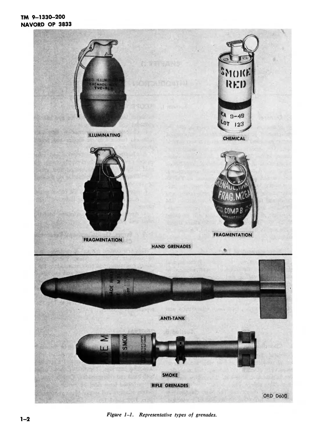
Certain grenades are designed to be thrown by hand
and others are designed to be projected from a rifle
by means of grenade launcher and a special grenade
launching cartridge. Figure 1-1 shows examples of
both hand and rifle grenades. Certain hand grenades
are projected from rifles by means of grenade pro-
jection adapters and special blank grenade cartridges
(para 3-12 and 3-13).
1-1
TM 9-1330-200
NAVORD OP 3833
FRAGMENTATION
CHEMICAL
FRAGMENTATION
HAND GRENADES
SMOKE
RIFLE GRENADES
ORD D600
Figure 1-1. Representative types of grenades.
1-2
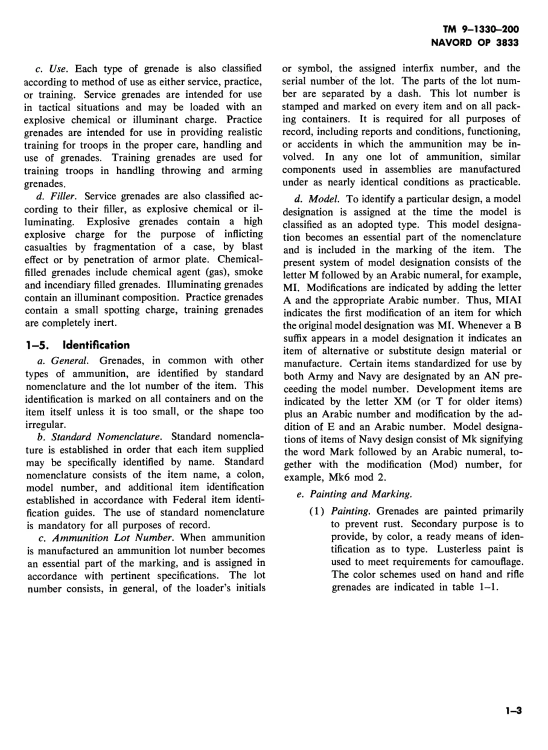
c. Use. Each type of grenade is also classified
according to method of use as either service, practice,
or training. Service grenades are intended for use
in tactical situations and may be loaded with an
explosive chemical or illuminant charge. Practice
grenades are intended for use in providing realistic
training for troops in the proper care, handling and
use of grenades. Training grenades are used for
training troops in handling throwing and arming
grenades.
d. Filler. Service grenades are also classified ac-
cording to their filler, as explosive chemical or il-
luminating. Explosive grenades contain a high
explosive charge for the purpose of inflicting
casualties by fragmentation of a case, by blast
effect or by penetration of armor plate. Chemical-
filled grenades include chemical agent (gas), smoke
and incendiary filled grenades. Illuminating grenades
contain an illuminant composition. Practice grenades
contain a small spotting charge, training grenades
are completely inert.
1 -5. Identification
a. General. Grenades, in common with other
types of ammunition, are identified by standard
nomenclature and the lot number of the item. This
identification is marked on all containers and on the
item itself unless it is too small, or the shape too
irregular.
b. Standard Nomenclature. Standard nomencla-
ture is established in order that each item supplied
may be specifically identified by name. Standard
nomenclature consists of the item name, a colon,
model number, and additional item identification
established in accordance with Federal item identi-
fication guides. The use of standard nomenclature
is mandatory for all purposes of record.
c. Ammunition Lot Number. When ammunition
is manufactured an ammunition lot number becomes
an essential part of the marking, and is assigned in
accordance with pertinent specifications. The lot
number consists, in general, of the loader’s initials
TM 9-1330-200
NAVORD OP 3833
or symbol, the assigned interfix number, and the
serial number of the lot. The parts of the lot num-
ber are separated by a dash. This lot number is
stamped and marked on every item and on all pack-
ing containers. It is required for all purposes of
record, including reports and conditions, functioning,
or accidents in which the ammunition may be in-
volved. In any one lot of ammunition, similar
components used in assemblies are manufactured
under as nearly identical conditions as practicable.
d. Model. To identify a particular design, a model
designation is assigned at the time the model is
classified as an adopted type. This model designa-
tion becomes an essential part of the nomenclature
and is included in the marking of the item. The
present system of model designation consists of the
letter M followed by an Arabic numeral, for example,
MI. Modifications are indicated by adding the letter
A and the appropriate Arabic number. Thus, MIAI
indicates the first modification of an item for which
the original model designation was MI. Whenever a В
suffix appears in a model designation it indicates an
item of alternative or substitute design material or
manufacture. Certain items standardized for use by
both Army and Navy are designated by an AN pre-
ceeding the model number. Development items are
indicated by the letter XM (or T for older items)
plus an Arabic number and modification by the ad-
dition of E and an Arabic number. Model designa-
tions of items of Navy design consist of Mk signifying
the word Mark followed by an Arabic numeral, to-
gether with the modification (Mod) number, for
example, Mk6 mod 2.
e. Painting and Marking.
(1) Painting. Grenades are painted primarily
to prevent rust. Secondary purpose is to
provide, by color, a ready means of iden-
tification as to type. Lusterless paint is
used to meet requirements for camouflage.
The color schemes used on hand and rifle
grenades are indicated in table 1-1.
1-3
ТМ 9-1330-200
NAVORD OP 3833
Table 1-1. Color Coding of Grenades
Grenades—color coded prior to implementation of MIL-STD 709 Grenades—color coded in accordance with MIL-STD 709
Type of grenade Color of body Color of marking Color of body Color of marking
HAND GRENADES
Fragmentation Olive drab Yellow Olive drab Yellow
Illuminating Unpainted Black All white or unpainted with white band Black
Practice Blue None or white Blue with brown band None or white
Training Blacki>2 None Blue2 None
RIFLE GRENADES
High explosive, antitank Olive drab Yellow Black Yellow
WP smoke Gray with yellow band and olive drab stabilizer assembly Yellow Light green with olive drab stabilizer assembly Light red and 1 yellow band
Colored smoke Gray with yellow band and olive drab stabilizer assembly Yellow Light green Black (Early production marked in white)3
Practice Black2 White Blue White
CHEMICAL HAND/RIFLE GRENADES
Nonpersistent casualty gas Gray Green and green band1 Gray Green and green band1
Persistent casualty gas Gray Green and green bands2 Gray Green and green bands2
Harassing (special purpose agents) Gray Red and red band1 Gray Red and red band1
WP (smoke) Gray Yellow and yellow band1 Light green Light red and 1 yellow band
Smoke (M18)4 Gray Yellow and yellow band1 Light green Black (Early production marked in white)
Incendiary Gray Purple and purple band1 Light red Black
Practice Blue White Blue White, yellow or brown band
Inert Black White (bronze or brass assemblies are unpainted) Blue White
Offensive Black Yellow Black Yellow
1 May have longitudinal white stripes painted 90 degrees apart around body.
2 This item is completely inert.
3 “CCC,” in the color of smoke produced, is marked on the ogive.
4 In addition to the standard color marking, the top of each M18 grenade is painted the color of the smoke produced by the grenade.
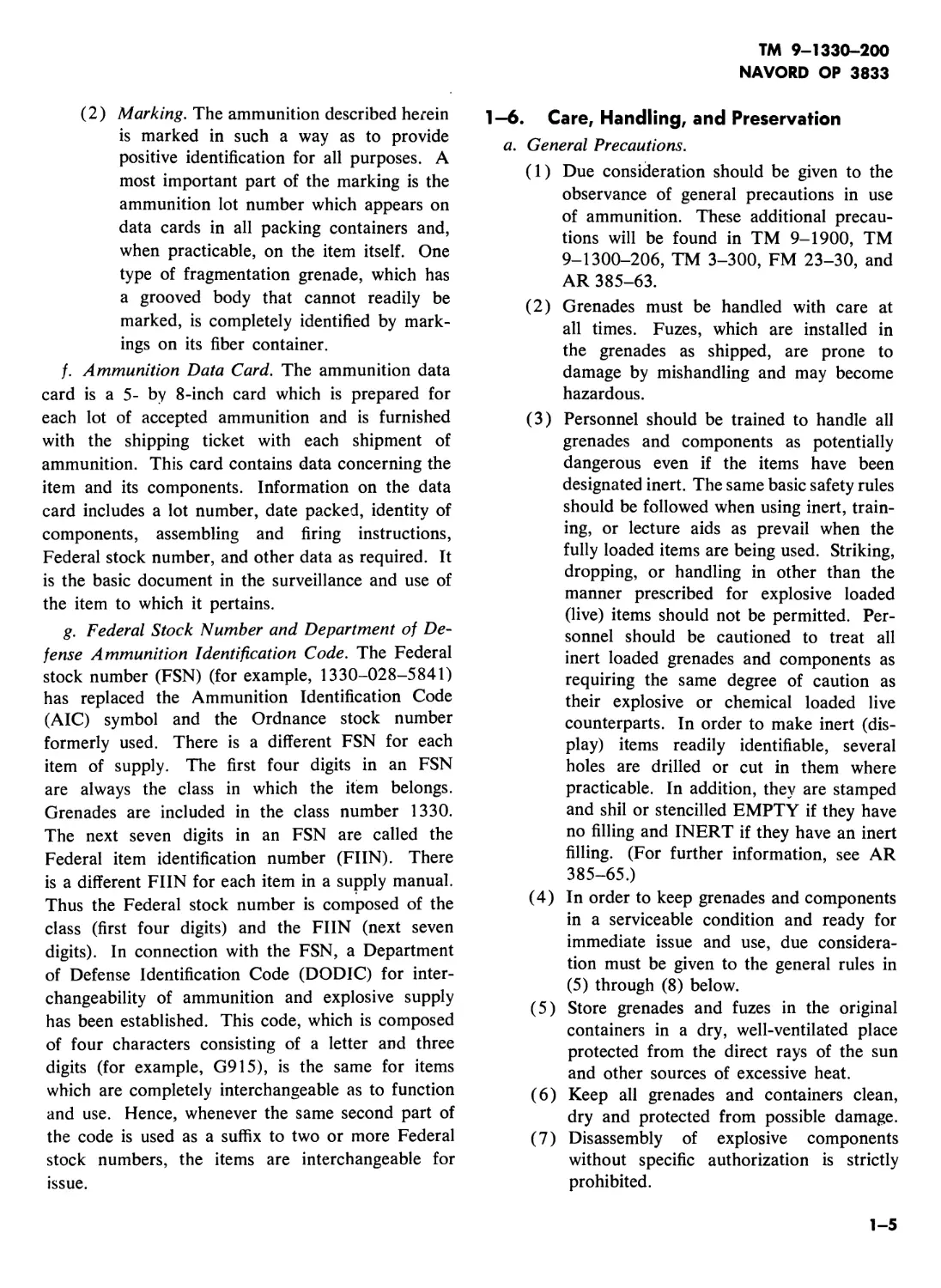
(2) Marking. The ammunition described herein
is marked in such a way as to provide
positive identification for all purposes. A
most important part of the marking is the
ammunition lot number which appears on
data cards in all packing containers and,
when practicable, on the item itself. One
type of fragmentation grenade, which has
a grooved body that cannot readily be
marked, is completely identified by mark-
ings on its fiber container.
f. Ammunition Data Card. The ammunition data
card is a 5- by 8-inch card which is prepared for
each lot of accepted ammunition and is furnished
with the shipping ticket with each shipment of
ammunition. This card contains data concerning the
item and its components. Information on the data
card includes a lot number, date packed, identity of
components, assembling and firing instructions,
Federal stock number, and other data as required. It
is the basic document in the surveillance and use of
the item to which it pertains.
g. Federal Stock Number and Department of De-
fense Ammunition Identification Code. The Federal
stock number (FSN) (for example, 1330-028-5841)
has replaced the Ammunition Identification Code
(AIC) symbol and the Ordnance stock number
formerly used. There is a different FSN for each
item of supply. The first four digits in an FSN
are always the class in which the item belongs.
Grenades are included in the class number 1330.
The next seven digits in an FSN are called the
Federal item identification number (FIIN). There
is a different FIIN for each item in a supply manual.
Thus the Federal stock number is composed of the
class (first four digits) and the FIIN (next seven
digits). In connection with the FSN, a Department
of Defense Identification Code (DODIC) for inter-
changeability of ammunition and explosive supply
has been established. This code, which is composed
of four characters consisting of a letter and three
digits (for example, G915), is the same for items
which are completely interchangeable as to function
and use. Hence, whenever the same second part of
the code is used as a suffix to two or more Federal
stock numbers, the items are interchangeable for
issue.
TM 9-1330-200
NAVORD OP 3833
1-6. Care, Handling, and Preservation
a. General Precautions.
(1) Due consideration should be given to the
observance of general precautions in use
of ammunition. These additional precau-
tions will be found in TM 9-1900, TM
9-1300-206, TM 3-300, FM 23-30, and
AR 385-63.
(2) Grenades must be handled with care at
all times. Fuzes, which are installed in
the grenades as shipped, are prone to
damage by mishandling and may become
hazardous.
(3) Personnel should be trained to handle all
grenades and components as potentially
dangerous even if the items have been
designated inert. The same basic safety rules
should be followed when using inert, train-
ing, or lecture aids as prevail when the
fully loaded items are being used. Striking,
dropping, or handling in other than the
manner prescribed for explosive loaded
(live) items should not be permitted. Per-
sonnel should be cautioned to treat all
inert loaded grenades and components as
requiring the same degree of caution as
their explosive or chemical loaded live
counterparts. In order to make inert (dis-
play) items readily identifiable, several
holes are drilled or cut in them where
practicable. In addition, they are stamped
and shil or stencilled EMPTY if they have
no filling and INERT if they have an inert
filling. (For further information, see AR
385-65.)
(4) In order to keep grenades and components
in a serviceable condition and ready for
immediate issue and use, due considera-
tion must be given to the general rules in
(5) through (8) below.
(5) Store grenades and fuzes in the original
containers in a dry, well-ventilated place
protected from the direct rays of the sun
and other sources of excessive heat.
(6) Keep all grenades and containers clean,
dry and protected from possible damage.
(7) Disassembly of explosive components
without specific authorization is strictly
prohibited.
1-5
ТМ 9-1330-200
NAVORD OP 3833
(8) Do not open fuze containers or remove
protective safety devices until just before
use.
(9) Return all grenades prepared for firing
but not fired to their original packing and
mark them appropriately.
(10) Observe all precautions listed throughout
this manual. For more detailed informa-
tion on care, handling and preservation,
and safety distance requirements for stor-
age and preparation of grenades, refer to
TM 9-1300-206.
b. Precautions in Handling. Grenades must not
be lifted or handled by the pull ring that is attached
to the safety pin of the fuze. The safety pin will be
removed just before throwing or just before launch-
ing and at no other time.
c. Precautions in Firing.
(1) The safety pin will not be pulled until just
before throwing or launching the grenade.
(2) During the safety pin removal, the safety
lever must be held firmly in place (as pre-
scribed in FM 23-30) until the grenade
is thrown, tossed or placed in position.
(3) Silent type fuzes (identified by a T-lug
which protrudes from the top of the fuze
to a slot in the safety lever) may be used
in some grenades. Under no conditions,
therefore, will the thrower consider the
grenade a dud because no noise, smoke, or
sparks are observed upon release of the
safety lever.
(4) Occasionally burning type grenades will
flash; hence, when used in maneuvers they
will be so thrown as to function not less
than 10 meters from personnel.
(5) Because white phosphorous (WP) par-
ticles cause burns and fires, WP grenades
used in training will be projected so that
they will burst at a distance of over 35
meters from all personnel, unless protec-
tion is afforded.
(6) Personnel should take cover after throwing
or projecting a WP grenade which contains
a bursting charge.
Caution: Particles of WP may not
burn when released into a moist area,
but will ignite when drier conditions
occur. WP can be expected to start
fires several days after a maneuver or
training exercise.
(7) If the safety lever on a WP grenade is
released accidentally, the grenade should
be thrown and personnel should take cover,
or if the grenade has been dropped with
the safety pin removed, personnel should
take cover immediately.
(8) Information concerning first aid measures
in the treatment of white phosphorous
burns will be found in TM 3-300 and
TM 8-285.
(9) Since fragments may be projected over 200
meters, fragmentation grenades will not be
used in training without adequate cover
(see FM 23-30).
(10) Rifle grenades with cracked or distorted
stabilizer assemblies will not be used.
(11) The appropriate rifle grenade and pre-
scribed combination of launcher and cart-
ridge must be used. Hand grenades must
be attached to an adapter and prescribed
combination of launcher and grenade
cartridge must be used to launch hand
grenades from a rifle.
(12) Rifle grenades or adapted hand grenades
must never be launched with any cartridge
other than the special grenade launching
cartridges provided for that purpose. Do
not use a bulleted cartridge to project a
grenade or a ground signal from a launcher
under any circumstances. Injury to per-
sonnel and damage of the rifle are pos-
sible.
(13) Detailed information concerning safety
precautions to be observed in firing gre-
nades will be found in AR 385-63, TM
3-300 and FM 23-30. Do not recover or
tamper with live grenades that have failed
to explode (duds). Duds will be disposed
of in accordance with the provision of TM
9-1300-206.
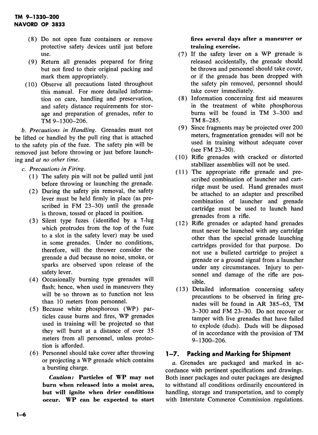
1-7. Packing and Marking for Shipment
a. Grenades are packaged and marked in ac-
cordance with pertinent specifications and drawings.
Both inner packages and outer packages are designed
to withstand all conditions ordinarily encountered in
handling, storage and transportation, and to comply
with Interstate Commerce Commission regulations.
1-6
TM 9-1330-200
NAVORD OP 3833
Figure 1-2. Typical packing boxes for grenades.
1-7
TM 9-1330-200
NAVORD OP 3833
Due consideration is given to packaging to prevent
the entrance of moisture. Packing and marking data
are given in Department of the Army SC 1305/30-
IL and SC 1340/98-IL. Typical packing and mark-
ings are illustrated in figure 1-2.
b. Marking includes all information required:
(1) For complete identification of contents.
(2) By the Interstate Commerce Commission
for shipping, including addresses of con-
signer and consignee and shipping desig-
nation of the contract.
(3) For intelligent handling, storage, and use.
c. For general information on packing and mark-
ing, refer to TM 9-1900.
d. For shipment, grenades are marked in ac-
cordance with Interstate Commerce Commission
regulations as required for specific items. See De-
partment of the Army SC 1305/30-IL and SC 1340/
98-IL.
1-8. T ransportation
Transportation of explosives by rail or truck in the
United States is regulated by “Interstate Commerce
Commission Regulations for Transportation of Ex-
plosives and Other Dangerous Articles by Freight”
published by the Bureau of Explosives, 30 Vesey
Street, New York, New York 10007. For additional
information on transportation, see TM 9-1300-206.
1-9. Field Storage
In oversea commands and combat areas the pro-
visions of TM 9-1300-206 and FM 9-5 should be
observed.
1-10. Reports and Forms
a. Accidents. Responsibilities and procedures for
preparation of reports of accidents and recording
Section III.
1-11. General
a. Description. Grenades are projectiles of a size
and shape convenient for throwing by hand or pro-
jecting from a rifle. The hand grenade is thrown by
hand in a prescribed manner and the rifle grenade is
projected by a special grenade launching cartridge
from a rifle equipped with a grenade launcher. The
and reporting requirements for Army accidents are
contained in AR 385-40.
b. Field Report of Accidents. If an accident or
malfunction involving the use of ammunition occurs
in training or combat, the occurrence will be re-
ported immediately to the technical service repre-
sentative under whose supervision the ammunition
for the unit involved is maintained or issued. A
report will be made by the officer in charge, or by
the senior noncommissioned officer or enlisted man
of the unit involved. All available pertinent facts
will be included in the report. It is the duty of a
qualified individual to investigate and report all such
incidents in accordance with AR 700-1300-8.
c. Fires. A fire report will be reported in all cases
of fire or explosion followed by fire that result in
loss of life, or damage (if estimated at $100.00 or
more) to Army equipment, materials, structures,
plants, systems, timber or grasslands or other pro-
perty (except motor vehicles or aircraft damaged
while in use) at all Department of the Army installa-
tions. For further information see AR 385-12.
Reports of fires or explosions followed by fire involv-
ing ammunition or other explosives are in addition
to reports specified in AR 385-40.
d. Report of Hazardous Conditions Involving
Military Explosives or Ammunition. Reports will
be submitted on all investigations concerning hazards,
accidents (b above), and safety of military explosives
and ammunition, in accordance with AR 385-60.
e. Forms. The forms generally applicable to the
information contained in this manual are listed in
appendix I. For information on use of certain
forms pertaining to ammunition records and pro-
cedures, refer to TM 38-750. The forms prescribed
for use throughout Department of the Army are
listed in DA Pam 310-2. Requisitions for these
forms will be submitted in accordance with AR
310-1.
DESCRIPTION
various types of hand grenades are used to supple-
ment small arms for effect against an enemy in close
combat for producing a harrasing agent, for smoke
screening and signaling, and for incendiary pur-
poses. The various types of rifle grenades are for
use against armored targets and for screening and
signaling smokes.
1-8
b. Explosive Train. The term explosive train re-
fers to the initiating and explosive elements of a
complete round. The components of an explosive
train are arranged according to their sensitivity from
the very sensitive initiating charge to the relatively
insensitive main charge. A typical high-explosive
grenade explosive train is illustrated in figure 2-5
(cross section), and consists of the following essential
components: the primer, the delay element, the
detonator (and booster), and the filler. The com-
plete round functions as described in (1) through
(5) below.
(1) The primer fires emitting an intense spit
of flame.
(2) The flame from the primer ignites the
delay element.
(3) The delay element burns for the pre-
scribed time delay.
(4) The delay element sets off the detonator.
In a low explosive grenade explosive train,
an igniter is used instead of the detonator.
(5) The detonator detonates the booster (when
present) and the explosive charge. In a
low explosive grenade (or irritant agent
grenade) the igniter functions the spotting
charge or agent filler.
1 -12. Hand Grenade
a. General. Hand grenade, as the name implies,
is intended primarily to be thrown by the individual
soldier. All standard Army hand grenades have a
delay-type fuze. The grenade will not function by
impact action but only after the burning of the delay
element in the fuze assembly has occurred. All HE
practice, and WP (smoke) grenades have a 4- to 5-
second delay. Irritant agent type, riot control gre-
nades and incendiary grenades have a 1.2 to 2-second
delay time.
b. Type. There are only four general types of
hand grenades described in detail in this manual:
Fragmentation, illuminating, chemical, and practice
and training hand grenades. A fifth type, an offensive
hand grenade, is now obsolete and no longer au-
thorized for use. The offensive hand grenade was
simply a cylindrical container filled with approxi-
mately 8 ounces of TNT. It was shipped without a
fuze and was used principally for blast effect. Al-
though offensive hand grenades are now obsolete,
fuzes for these hand grenades are still available for
issue and use when authorized. When a blast effect
TM 9-1330-200
NAVORD OP 3833
hand grenade is desired, a 14 pound or Уг pound
demolition charge fitted with an offensive hand
grenade fuze or a delay detonator may be used (para.
4-2).
(1) Fragmentation hand grenades. Fragmenta-
tion hand grenades are used to produce
casualties by the high velocity projection
of fragments of the grenade case. Frag-
mentation hand grenades have an effective
casualty radius up to 15 meters.
(2) Illuminating hand grenades. Illuminating
hand grenades are used to illuminate ter-
rain in night operations. They provide
55,000 candlepower for a period of 25
seconds.
(3) Chemical hand grenades. Chemical hand
grenades are used for incendiary, screen-
ing, signaling, training, or riot control
purposes.
(4) Practice and training hand grenades. Prac-
tice and training hand grenades are de-
signed for training personnel in care, hand-
ling and use of service rifle grenades.
1-13. Rifle Grenades
a. General. Rifle grenades are especially de-
signed for projection from a grenade launcher at-
tached to the muzzle of the rifle. Hand grenades
may also be adapted for projection from a rifle
by means of a projection adapter (paras. 3-12 and
3-13 and figs. 3-7 and 3-8). A special grenade
cartridge is used in the rifle to project the grenade.
Grenade sights help obtain first round hits on the
target. Rifle grenades may be used against armored
targets, against personnel, for screening or signaling,
or for incendiary effect against flammable targets.
Rifle grenades may be fired at low angles (direct fire)
(used against tanks) or high angles (indirect fire),
depending on the type of grenade being fired and
effect desired.
b. Types. Three general types of rifle grenades
are described in this manual: high-explosive anti-
tank, practice, and chemical.
(1) High-explosive antitank rifle grenades.
Antitank rifle grenades, as the name im-
plies, are intended for use against armored
targets. An antitank rifle grenade is es-
sentially a small shaped charge capable of
penetrating 10 inches of armor plate or 20
1-9
TM 9-1330-200
NAVORD OP 3833
inches of reinforced concrete at an effective
range of 115 meters.
(2) Practice rifle grenades. Practice rifle gre-
nades are designed for training personnel
in care, handling and use of service rifle
grenades.
(3) Chemical rifle grenades. Chemical rifle
grenades are used primarily for the pro-
duction of smoke, either for screening or
signaling purposes. In addition, the white
phosphorous grenade can also be used for
incendiary effect against flammable targets.
Chemical grenades function either on im-
pact with the targets to produce clouds of
smoke or upon projection to produce a
long trail of smoke through the air.
1—14. Related Items
The grenades and components described in
chapters 2 and 3 all belong to Federal supply class
1330. Other items used in conjunction with, or in
lieu, of grenades are covered in other publications.
These items include demolition charges, firecrackers,
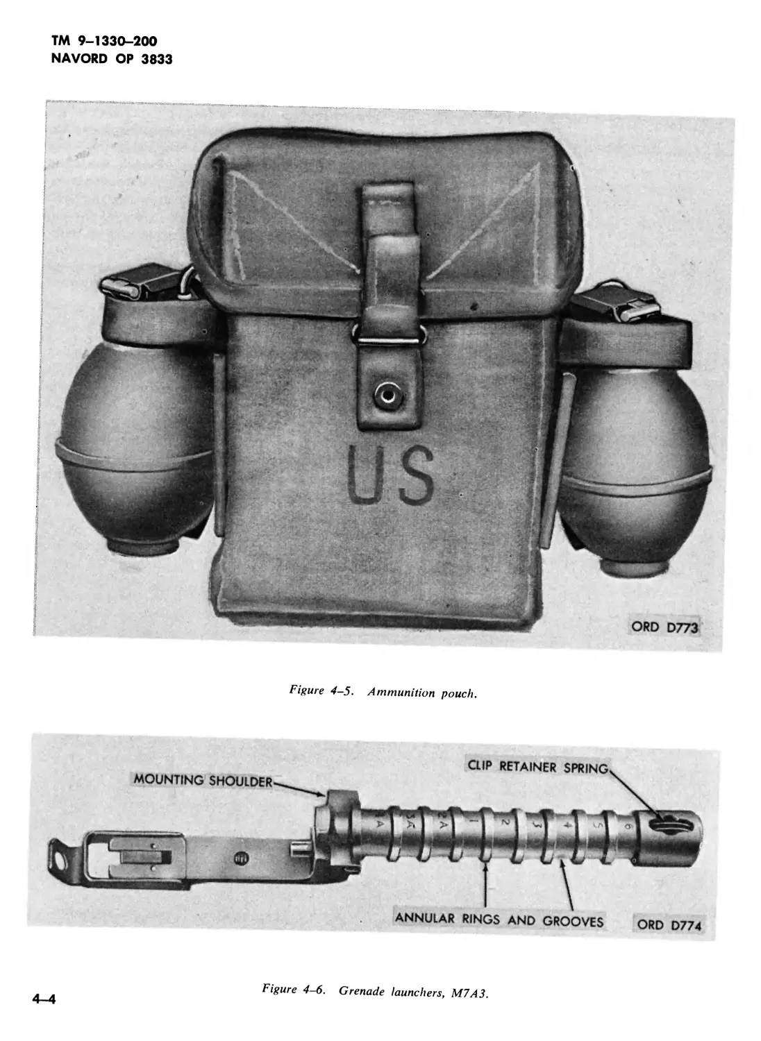
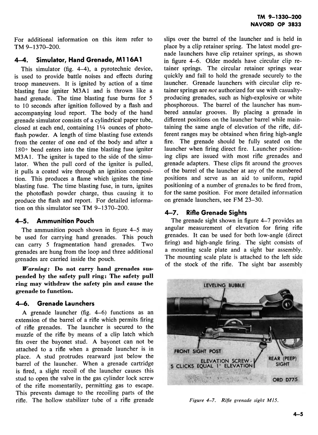
hand grenades, simulators, ammunition pouches, rifle
grenade launchers and rifle grenade sights. These
items are described briefly in chapter 4.
1-10
TM 9-1330-200
NAVORD OP 3833
CHAPTER 2
HAND GRENADES
Section I. INTRODUCTION
2—1. General
Hand grenades (fig. 1-1) are small high-explosive
(HE) or chemical filled missiles designed to be hand
thrown by the individual soldier. The maximum
range that the average trained soldier can throw a
grenade is 40 meters. The range of a hand grenade
may be increased to approximately 160 meters by
projecting it from a rifle by means of a projection
adapter (paras. 3-11, 3-12, and 3-13). There are
five basic types of hand grenades—fragmentation,
offensive, illuminating, chemical, and practice and
training. Hand grenades may be used against a
variety of targets at close range for producing
casualty or for blast effect. They may also be used
for signaling, illuminating and screening (smoke).
For detailed information on tactical use of hand
grenades, see FM 23-30,
Figure 2-1. Typical outer packing for hand grenades.
2-2. Data
A complete list of currently available hand gre-
nades and components is given in Department of
the Army SC 1305/30-IL and SC 1340/98-IL.
Figures 2-1 and 2-2 show typical outer and inner
packings, respectively, for hand grenades. Detailed
technical information on the various hand grenades
and components available is given in paragraphs 2-3
through 2-22.
Figure 2-2. Typical inner fiber container for
hand grenades.
2-1
TM 9-1330-200
NAVORD OP 3833
Section II. FRAGMENTATION HAND GRENADES
2-3. General
a. High explosive hand grenades may be em-
ployed for two different types of effect: fragmenta-
tion effect and blast effect. Fragmentation hand
grenades are used primarily for fragmentation effect,
however, the blast effect of fragmentation hand
grenades may be used effectively in small enclosed
places. The fragmentation effect of a grenade is
most effective against a scattered deployment of
personnel because the effective range of high speed
missiles (fragments of the grenade body projected
by the explosion) is much greater than the effective
radius of the blast effect. For example, the effective
casualty radius (because of fragmentation effect) of
the fragmentation hand grenade M26A2 is 15 meters
whereas the effective casualty radius (because of blast
effect) of a Vi pound TNT demolition charge (para.
4-2) is only 2 meters. Blast effect is most effective
in inclosed spaces. When the primary effect desired
is blast effect, a TNT demolition charge (para. 4-2)
is preferable because none of the explosive force is
expended in expanding and rupturing a fragmentation
case. The average soldier can throw a fragmentation
hand grenade from 30 to 40 meters. By means of a
grenade projection adapter, a fragmentation hand
grenade may be projected from a rifle (paras 3-11
and 3-12) thus increasing its maximum range to
approximately 160 meters. There are two basic
types of fragmentation hand grenades: the older
fragmentation hand grenade Mk2 (fig. 2-3) (para.
2-4) and the newer improved fragmentation hand
grenade M26 series (fig. 2-4) (para. 2-5). These
two types are functionally the same but the M26
has much greater casualty-producing power in the
area of burst and is less hazardous from the stand-
point of stray fragments at extended distances.
b. Precautions.
(1) If a grenade is dropped after the safety pin
has been removed, pick it up and throw it.
A hand grenade can be picked up and
thrown much faster than a soldier can run
in 4 to 5 seconds.
(2) Do not attempt to disassemble a frag-
mentation hand grenade.
(3) Follow all precautions listed in paragraph
1-6 as well as those listed in paragraphs
2-4 and 2-5. For additional precautions
in tactical use of fragmentation hand gre-
Figure 2-3. Grenade, hand: fragmentation, Mk2, w/fuze M204A1
2-2
TM 9-1330-200
NAVORD OP 3833
nades refer to FM 23-30, TM 9-1300-
206, and AR 385-63.
2—4. Grenade, Hand: Fragmentation, Mk2
a. General. Fragmentation hand grenade Mk2
(fig. 2-3) is an older type grenade. It is the grenade
from which the term “pineapple” was derived be-
cause of its deeply serrated body. These deep
serrations delineate the fragmentation of the body
when the grenade explodes. The grenade Mk2 is no
longer being manufactured. As present stocks are
depleted, the Mk2 is being replaced by the improved
design of the grenades M26-series (para. 2-5).
b. Description.
(1) General. The grenade Mk2 consists es-
sentially of three basic parts: an explosive
charge, a body, and a fuze. This grenade
is issued with fuze M6A4C, M204A1, or
M204A2. The three fuzes function the
same. They differ in such physical details
as shape of body, shape of lever, and
loading. The M6A4C is a noisy, spark-
and-smoke-producing fuze. The fuzes
M204A1 and M204A2 (improved versions
of the earlier fuze M2043 are noiseless,
sparkless, smokeless types.
(2) Data.
Model number .........................Mk2
Type .........................fragmentation
Weight ..........................21 ounces
Explosive charge.....2 ounces of flaked TNT
Dimensions......Length, 4.5-inches; diameter,
2.25-inches
Body..............................Cast iron
Fuze: model number.....M6A4C, M204A1, or
M204A2
Type....................delay detonating
Delay time................4 to 5-seconds
Color......................See table 1-5-1
c. Functioning. As issued, the hand grenade fuze
is cocked and ready to fire. After the safety pin is
withdrawn and the grenade thrown (e below), it
functions as follows:
(1) The striker, driven by its spring, forces the
safety lever out of its path; the safety lever
flies free of the grenade and releases the
striker.
(2) The striker strikes the percussion primer.
(3) The primer emits a small intense spit of
flame igniting the delay element.
(4) The delay element burns for 4 to 5 seconds
and sets off detonator.
(5) The detonator explodes and detonates the
explosive charge.
(6) The explosive charge explodes rupturing
the body and projecting fragments, some
of which may be dangerous as far as 185
meters.
d. Preparation for Use.
(1) Remove fiber container from packing case.
(2) Carefully remove cover of fiber container
and inspect grenade before removing. The
grenade, as issued, is packed in the fiber
container with its fuze up.
(3) Inspect to see that safety pin is in place
and undamaged and that the legs of the
safety pin are spread apart (approximately
30°).
Warning: If the grenade is packed
upside down or the safety pin is not
properly in place, do not attempt to
remove the grenade from its fiber con-
tainer. Replace the cover and return
the container to the responsible am-
munition supply personnel.
(4) Remove grenade from fiber container and
inspect for obvious defects which would
affect functioning. Inspect for cracked
grenade, broken safety lever, broken lugs,
and damaged safety pins and pull rings.
Dispose of defective grenades as in (3)
above.
e. To Fire.
(1) Grasp grenade in hand, holding safety lever
against the grenade body with thumb.
(2) With other hand pull safety pin pull-ring
with a twisting-pulling motion holding
safety lever tightly against the grenade
body.
Note. A pull of 10 to 30 pounds should re-
move safety pin.
(3) Throw grenade and take cover immedi-
ately.
(4) Observe precautions listed in paragraphs
1-6 and 2-3.
f. Disarming. Once the safety pin has been re-
moved the grenade is armed and must be thrown.
Do not attempt to replace the pin in order to return
it to a safe condition.
g. Capabilities. The average soldier can throw
the fragmentation grenade Mk2 approximately 30
2-3
TM 9-1330-200
NAVORD OP 3833
meters. The effective casualty radius is 10 meters.
Fragments may be projected as far as 185 meters.
2-5. Grenade, Hand: Fragmentation,
M26—Series
a. M26-Series Grenades (Except M26A2 w/Fuze
M217).
(1) General. Hand grenades, M26-series (fig.
2-4), were developed as replacements for
fragmentation hand grenade Mk2 (para.
z 2-4). Hand grenades, M26-series, have a
larger explosive charge and a more effec-
tive casualty radius, are lighter than the
older grenades Mk2 and produce more
fragments than Mk2 grenades. Fragments,
though smaller than those produced by
Mk2 grenades, have a higher initial veloc-
ity.
(2) Description.
(a) General. The grenade, M26-series, con-
sists of three basic parts: an explosive
charge, a body, and a fuze. The body
consists of a smooth thin sheet steel
shell. The inside of the shell is lined
with a notched fragmentation wire coil.
Three models of the grenades Mi-
series are available: M26, M26A1, and
the M26A2. The M26 is issued with
fuze M204A1 or M204A2; the M26A1
with fuze M204A2; and the M26A2 is
issued with fuze М215 (fig. 2-5). These
fuzes, functionally similar, differ only in
such physical details as shape of body,
shape of safety lever, loading, and diame-
ter of fuze threads.
Note. The fuzes M204-series and М215-
series can not be used interchangably.
(b) Data.
Model number........M26, M26A1 or M26A2
Type ........................Fragmentation
Weight ...........................16 ounces
Explosive charge....5.5-ounces of Comp. В
Dimensions.....Length, 3.9-inches; diameter,
2.25-inches
Body. .....Thin sheet steel lined with notched
fragmentation coil
Fuze: model number......M204A1 or M204A2
with grenade M26; M204A? with grenade
M26A1; M215 with grenade М26A2
Type ...................delay detonating
Delay time..............4 to 5 seconds
Color..........................See table 1-1
(3) Functioning. Similar to Mk2 functioning
(para. 2-4c).
Figure 2-4. Grenade, hand: fragmentation, M26, w/fuze M204A.
2-4
TM 9-1330-200
NAVORD OP 3833
SPRING
PRIMER M42
PRIMER HOLDER
BODY
DELAY COLUMN
IGNITER CHARGE
UPPER CHARGE
LOWER CHARGE
DETONATOR ASSEMBLY
Figure 2-5. Fuze, hand grenade, M215.
PULL RING ASSEMBLY
ORD D602
(4) Preparation for use. Similar to Mk2 prep-
aration for use (para. 2-4d).
(5) To fire. See paragraph 2-4e.
(6) Disarming. See paragraph 2-4/.
(7) Capabilities. The average soldier can throw
the fragmentation grenade M26-series ap-
proximately 40 meters. The effective
casualty radius is 15 meters, fragments are
projected much further.
b. Grenade, Hand: Fragmentation, M26A2 w/
Fuze, Hand Grenade: М217.
(1) General. The fragmentation hand grenade
M26A2 with fuze М217 was developed
as a replacement for fragmentation hand
grenades Mk2, M26, and M26A1 with
fuzes M204A1 and M204A2 and grenade
M26A2 with fuze М215. Fuze М217,
developed in order to provide an impact
capability for the hand grenade, normally
functions on impact. However, if impact
occurs prior to arming or impact is in-
sufficient to function fuze, the fuze will
function within 3 to 7 seconds after the
lever is released. Grenade M26A2 as-
sembled with fuze М217 (impact and de-
lay functioning) can be distinguished from
the grenade M26 Series assembled with
the delay-functioning-type fuze (e.g.,
M204-series and М215) in that the lever
2-5
TM 9-1330-200
NAVORD OP 3833
for fuze М217 is marked IMPACT in
raised (embossed) lettering while the levers
for the delay-functioning-only types are
unmarked.
(2) Description.
(a) General. The fragmentation hand gre-
nade M26A2 with fuze М217 (fig. 2-6)
consists of three basic: an explosive
charge, a grenade body, and an electric
impact-functioning fuze with an over-
riding delay-function feature. The body
consists of a smooth, thin-sheet, steel
shell. The inside of the shell is lined
with a notched fragmentation wire coil.
(ft) Fuze, M217. Fuze M217 (fig. 2-7) is
equipped with a safety pin and pull
ring. The split end of the safety (cotter)
pin is spread to prevent accidental re-
moval and arming during shipping
and handling. The pull ring is provided
to facilitate removal of the safety pin
for arming.
Note. A pull of 10 to 30 pounds is re-
quired to withdraw the safety pin.
Warning: Accidental removal of
the safety pin and release of the
lever will result in arming of the
fuze followed by detonation of the
grenate within 3 to 7 seconds.
The major components of fuze М217
are as follows: a bouchon assembly, a
fuze body assembly (which contains
a thermal power supply, a thermal-arm-
ing disk, a delay-function switch, an
impact switch and an electric detonator),
and an RDX booster pellet. The fuze
body components are assembled in a
steel case 2.7 inches in length and ap-
proximately Уг inch in diameter. The
fuze weighs 2.68 ounces. The bouchon
assembly consists of a pull ring, a safety
(cotter) pin, a striker, a hinge pin, a
striker spring, a bouchon body and a
lever. The fuze body assembly is hermet-
ically sealed.
Figure 2-6. Grenade, hand: Fragmentation, M26A2 w/fuze,
hand grenade: М217—cross section and external view.
2-6
TM 9-1330-200
NAVORD OP 3833
Figure 2-7. Fuze, hand grenade: М217—cross section and external view.
(c) Data.
1. Grenade.
Model ..................................M26A2
Type ........................Fragmentation
Weight (w/o fuze)............12.52 ounces
(w/fuze) ............15.20 ounces
Explosive charge . 6.3 ounces Composition В
Dimensions:
Length (w/fuze) ............. 3.81 inches
(w/o fuze) ............3.33 inches
Diameter......................2.25 inches
Material......Thin sheet steel, lined with
notched fragmentation coil
2. Fuze.
Model .................................М217
Type .............Electric-impact functioning
with an overriding delay-function feature
Weight ...........................2.68 ounces
Dimensions:
Length ......... 2.7 inches (visible 0.5-in.)
Diameter ....................0.57-inch
Primer:
Model ........................... M42G
Type........................Percussion
Detonator:
Model .............................T77
Type .........................Electric
Arming:
Method............Remove safety pin and
release lever
Time of Arming Delay.......1 to 2 seconds
(3) Functioning. Upon releasing the lever, the
striker assembly, through the action of the
spring, throws off the lever and impacts
the percussion primer. The primer initiates
the thermal power supply which causes the
fuze to arm within 1 to 2 seconds. After
arming, the grenade will function:
(a) Upon proper impact—on impact
2-7
TM 9-1330—200
NAVORD OP 3833
(b) If proper impact does not occur—on
delay
(c) If no impact occurs—on delay.
Note. Release of the lever always com-
mits the grenade to detonation.
If the fuze fails to function, after release of
the lever, it will become a dud within 30
seconds. Throwing the grenade to a height
of at least 16 feet above ground assures
adequate time for the fuze to arm prior to
impact. This will provide maximum ef-
fective use of the impact functioning fea-
ture.
Note. At high temperatures ( + 125°F.), the
arming time may be as short as 1.0 second while
at low temperatures (—40°F.), the arming time
may be as long as 2.0 seconds. The delay func-
tion device functions within 3 to 7 seconds
throughout the temperature range of —40°F. to
+ 125°F.
(4) Preparation for use.
Note. Hand grenade M26A2 with fuze М217
is not intended for use as a rifle grenade.
(a) Remove fiber container from packing
case.
(b) Carefully remove cover of fiber con-
tainer and support from top of grenade.
Note. Inspect grenade prior to removing
from container. The grenade, as issued, is
packed in the fiber container with the fuze
upwards.
(c) Inspect for lever position and condition,
and that the legs of the safety (cotter)
pin are spread apart.
Warning: If the grenade is found
to be packed upside down or the
safety pin is not properly in place,
do not attempt to remove the gre-
nade from the fiber container. Re-
place the support and cover and
return the container to qualified am-
munition personnel for disposition.
(d) Remove the grenade from fiber con-
tainer and inspect for defects which may
affect functioning, such as, cracked gre-
nade body, broken lever, broken lugs,
and damaged safety pins and pull rings.
Dispose of defective grenades as indi-
cated in (c) above.
(5) Use.
(a) Grasp grenade in hand, holding lever
firmly against the grenade body.
(b) With the other hand, pull safety pin
pull ring with a twisting pulling motion
holding lever tightly against the grenade
body.
(c) If a grenade is accidentally dropped after
the pull ring assembly has been removed
from the fuze, or the striker allowed to
function, it is safe to recover and throw
the grenade within three seconds follow-
ing release of the lever, provided care
is taken to prevent additional impact
or sudden shock.
(d) Throw grenade so that it attains a height
of at least 16 feet above the ground
(fig. 2-8) and thus allows adequate time
for fuze to arm prior to impact. Take
cover immediately. Do not attempt to
observe functioning.
Note. Rolling or bouncing grenade towards
the target will detonate the grenade.
(6) Precautions in use. In addition to the pre-
cautions contained in TM 9-1900, FM
23-30, and AR 385-63, the following
precautions should be observed.
Note. Hand grenade M26A2 with fuze М217
is not intended for use as a rifle grenade.
(a) Hand grenades with fuzes must never
be lifted or handled by the pull ring
assembly.
(b) Do not pull the safety pin of the pull
ring assembly or release the lever until
the grenade is to be thrown.
(c) Avoid additional impact or sudden shock
to grenades in which strikers have been
allowed to function.
(d) Fuzes will not be removed from hand
grenades.
(7) Disarming. Once the safety pin has been
removed, the grenade should be thrown.
Do not attempt to replace the pin in order
to safe the grenade.
(8) Capabilities. The average soldier can throw
the grenade M26A2 approximately 40
meters. The effective casualty radius is 15
meters; fragments are projected much
further.
(9) Care, handling, and preservation. The gen-
eral provisions for care, handling, and
preservation of hand grenades contained
2-8
TM 9-1330-200
NAVORD OP 3833
Figure 2-8. Impact functioning use of hand grenade M26A2 w/fuze М217.
in TM 9-1300-206 are applicable to hand
grenades with fuze М217.
(10) Painting and marking. The grenade is
painted olive drab and marked in yellow.
A yellow band approximately 14 inch in
diameter is stenciled at the top of the
grenade. The lever of the fuze М217 is
marked IMPACT in raised (embossed)
lettering.
(11) Packing and marking.
(a) Packing. Thirty packing containers are
packed two layers deep in a wooden
box. The box dimensions (in inches)
are 19% by 11-9/16 by 12-1/32. The
box with packing containers weighs ap-
proximately 51.0 pounds.
(fe) Marking. All boxes and containers are
marked in accordance with the pro-
visions of TM 9-1900 and TM 9-1300-
206.
Section III. ILLUMINATING HAND GRENADES
2—6. General
a. Description. Illuminating hand grenades are
used principally for signaling and for battlefield il-
lumination. They are used in a manner similar to
that of ground signals (TM 9-1370-200). The
principal difference between illuminating hand gre-
nades and ground signals is that illuminating gre-
nades are designed to burn on the ground and ground
signals are designed to burn while suspended from a
parachute. Illuminating hand grenades may be
thrown by hand or projected from a rifle by using a
projection adapter (para. 3-12) and a grenade
launcher. Illuminating hand grenades should not be
used on soggy or swampy ground; they may become
embedded, with the result that little or no illumina-
tion is produced. The illuminating compound burns
with a very hot flame and may be used for incendiary
purposes against flammable targets. Because of its
incendiary nature, caution should be exercised in the
use of illuminating hand grenades to prevent fires
which would be detrimental to tactical operations.
For detailed information on battlefield illumination,
see FM 20-60.
b. Precautions. Although illuminating hand gre-
nades are not considered casualty-producing agents,
death or serious injury may result if they are not
handled properly Illuminating hand grenades must
be protected from moisture and excessive heat. The
2-9
TM 9-1330-200
NAVORD OP 3833
following precautions will be observed when handling
or throwing illuminating hand grenades. Additional
precautions may be found in paragraph 1-6, TM
9-1300-206, and FM 23-30.
(1) Do not remove illuminating hand grenade
from sealed container until just before use.
(2) Do not pick up an illuminating hand gre-
nade by the safety pin pull ring.
(3) If an illuminating grenade is dropped after
the safety pin has been removed, pick it up
quickly and throw it. An illuminating
hand grenade can be thrown much further
than a soldier can run in the remaining delay
time (7 seconds total delay) of the fuze.
(4) Do not recover or tamper with illuminating
grenades that have failed to function.
These duds are to be recovered and de-
stroyed only by qualified personnel.
(5) Grenades that are cracked, dented or de-
formed, should not be used.
(6) Do not tamper with, or attempt to dis-
assemble illuminating grenades.
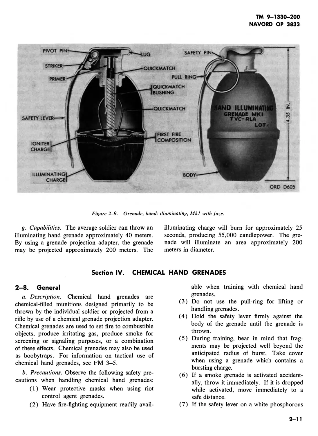
2—7. Grenade, Hand: Illuminating, Mkl
a. General. This grenade (fig. 2-9) resembles, in
outward appearance, the fragmentation hand gre-
nade M26 series. The Mkl is the only type of il-
luminating hand grenade currently available and was
developed by the Navy. It is used for illuminating
and signaling purposes. The grenade may also be
used as an incendiary grenade to start fires in dry
grass, leaves, or brush.
b. Description.
(1) General. The illuminating hand grenade
Mkl consists of three basic parts: an
illuminating charge, a body, and a fuze.
The illuminating charge consists of a pyro-
technic composition ignited by a first fire
composition which, in turn, is ignited by an
igniter charge. The body is fabricated
from thin sheet steel. The fuze is a special
igniter-type fuze. The igniter consists of a
quickmatch contained in a quickmatch
bushing.
(2) Data.
Model number ...............................Mkl
Type ..........................Illuminating
Weight..............................10 ounces
Illuminating charge . 3.5 ounces of pyrotechnic
composition
Candlepower ...................... 55,000
Dimensions:
Length ......................4.35 inches
Diameter.....................2.19 inches
Body ........................Thin sheet steel
Fuze:
Type .................... Delay igniting
Delay time....................7 seconds
Color .......................See table 1-1
c. Functioning. As issued, the igniter fuze is
cocked and ready to fire. When the safety pin is
withdrawn and the grenade thrown, it functions as
follows:
(1) The striker, driven by its spring, forces the
safety lever out of its path; the safety lever
flies free from the grenade, releasing the
striker.
(2) The striker strikes the percussion primer.
(3) The primer emits a small intense flame,
igniting the quickmatch.
(4) The quickmatch burns for 7 seconds and
ignites igniter charge.
(5) The igniter charge ignites first fire com-
position.
(6) The first fire composition ignites illumi-
nating charge.
(7) The gas pressure produced by burning of
illuminating charge causes upper half of
body with fuze to be separated from the
lower half containing the burning illumi-
nating composition.
d. Preparation for Use. This grenade is prepared
for use in the same manner as the fragmentation
hand grenade Mk 2, as explained in paragraph 2-4J.
e. To Fire. This grenade is fired in the same man-
ner as the fragmentation hand grenade Mk 2, as ex-
plained in paragraph 2-4e.
Warning 1; When the two halves of the body
are separated by the burning of the illuminating
charge, they may be projectetl with considerable
velocity. Friendly troops in the area should take
cover until the illumination can be seen.
Warning 2: The illuminating composition
burns with intense heat. Care must be taken to
avoid throwing the grenade where it may start
a dangerous fire.
f. Disarming. Once the safety pin has been re-
moved, the grenade is armed and must be thrown.
Do not attempt to replace the pin in order to return
it to a safe condition.
2-10
TM 9-1330-200
NAVORD OP 3833
Figure 2-9. Grenade, hand: illuminating, Mkl with fuze.
g. Capabilities. The average soldier can throw an
illuminating hand grenade approximately 40 meters.
By using a grenade projection adapter, the grenade
may be projected approximately 200 meters. The
illuminating charge will burn for approximately 25
seconds, producing 55,000 candlepower. The gre-
nade will illuminate an area approximately 200
meters in diameter.
Section IV. CHEMICAL HAND GRENADES
2-8. General
a. Description. Chemical hand grenades are
chemical-filled munitions designed primarily to be
thrown by the individual soldier or projected from a
rifle by use of a chemical grenade projection adapter.
Chemical grenades are used to set fire to combustible
objects, produce irritating gas, produce smoke for
screening or signaling purposes, or a combination
of these effects. Chemical grenades may also be used
as boobytraps. For information on tactical use of
chemical hand grenades, see FM 3-5.
b. Precautions. Observe the following safety pre-
cautions when handling chemical hand grenades:
(1) Wear protective masks when using riot
control agent grenades.
(2) Have fire-fighting equipment readily avail-
able when training with chemical hand
grenades.
(3) Do not use the pull-ring for lifting or
handling grenades.
(4) Hold the safety lever firmly against the
body of the grenade until the grenade is
thrown.
(5) During training, bear in mind that frag-
ments may be projected well beyond the
anticipated radius of burst. Take cover
when using a grenade which contains a
bursting charge.
(6) If a smoke grenade is activated accident-
ally, throw it immediately. If it is dropped
while activated, move immediately to a
safe distance.
(7) If the safety lever on a white phosphorous
2-11
TM 9-1330—200
NAVORD OP 3833
(WP) grenade is released accidentally,
throw the grenade and take cover; or if
the grenade has been dropped with the
safety pin removed, pick up the grenade,
throw it, and take cover. The 4 to 5-
second fuze delay of the WP grenade al-
lows time for this procedure.
(8) See TM 9-1900 for additional safety pre-
cautions.
c. Misfires. Burning-type grenades which have
misfired may be approached and retrieved after 5
minutes. Misfired bursting-type grenades should be
destroyed in place by authorized disposal personnel.
Do not remove a burning-type grenade from the
sealed container in which it is packaged until shortly
before the grenade is to be used. Exposure of an
unpackaged grenade to rain or high atmospheric
humidity will cause the grenade to misfire.
d. Operation in Extreme Cold. Extreme cold does
not affect the functioning of chemical hand grenades
unless ice has formed where it will interfere with
functioning of the fuze. Chemical hand grenades tend
to bury themselves in deep snow, drastically reducing
their effectiveness. When the ground is covered by
deep snow, place signaling or screening grenades on
a board or other insulating material, if possible.
Throw or launch bursting grenades so that they burst
before they strike the surface of the snow. In snow,
red smoke has the best visibility, then green, violet
and yellow, with white having the least visibility.
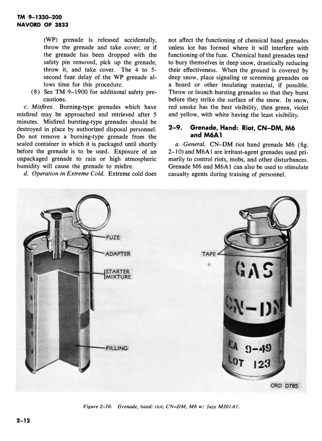
2-9. Grenade, Hand: Riot, CN-DM, M6
and M6A1
a. General. CN-DM riot hand grenade M6 (fig.
2-10) and M6A1 are irritant-agent grenades used pri-
marily to control riots, mobs, and other disturbances.
Grenade M6 and M6A1 can also be used to stimulate
casualty agents during training of personnel.
ORD D785
Figure 2-10. Grenade, hand: riot, CN-DM, M6 w/ fuze M201A1.
2-12
TM 9—1330—200
NAVORD OP 3833
b. Description.
(1) General. The bodies of grenade M6 and
M6A1 are made of thin sheet-metal cylin-
drical containers 2.5 inches in diameter
and 4.5 inches high. Grenade M6 has 6
emission holes in the top and 18 emission
holes in the sides. The M6A1 has five
emission holes: one in the bottom and
four in the top. The emission holes are
covered with pressure-sensitive tape to pro-
tect the filling from moisture. The filling is
coated with a starter mixture which aids
ignition. Grenade M6A1 differs from the
M6 in that the CN and DM filling is not
intimately mixed but is pressed into in-
dividual cups, packed in the grenade body
in such manner that there is no contact be-
tween the two types of filling before igni-
tion of the grenade. The bottom of the
grenade body is covered with an asbestos
gasket. An asbestos disk, pierced with five
holes which correspond to the holes in the
top of the grenade, is crimped to the under-
side of the top of the grenade.
(2) Data.
Model number .................. M6 or M6A1
Type ................. ........Irritant agent
Weight..............(M6) 1.06 pounds; (M6A1)
1.25 pounds
Charge.....(M6) 0.64 pound CN-DM; (M6A1)
4.6 ounces DM, 4.9 ounces CN
Dimensions:
Diameter.................................2.5 inches
Height ..........................4.5 inches
(without adapter)
Body.......................................Sheet metal
Fuze ....................................M201A1
Type.......................Delay igniting
Delay time.................1.2 to 2 seconds
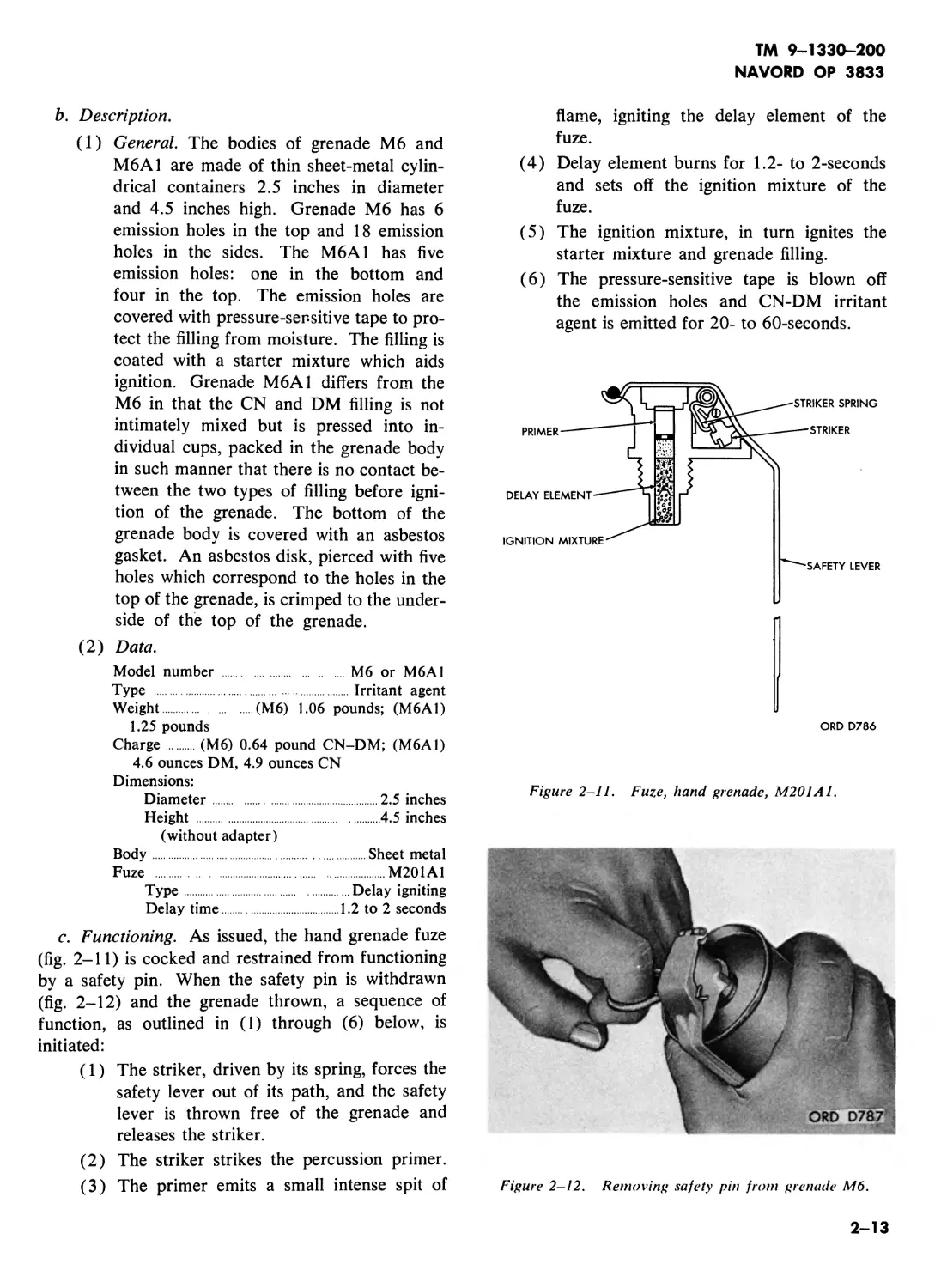
c. Functioning. As issued, the hand grenade fuze
(fig. 2-11) is cocked and restrained from functioning
by a safety pin. When the safety pin is withdrawn
(fig. 2-12) and the grenade thrown, a sequence of
function, as outlined in (1) through (6) below, is
initiated:
(1) The striker, driven by its spring, forces the
safety lever out of its path, and the safety
lever is thrown free of the grenade and
releases the striker.
(2) The striker strikes the percussion primer.
(3) The primer emits a small intense spit of
flame, igniting the delay element of the
fuze.
(4) Delay element burns for 1.2- to 2-seconds
and sets off the ignition mixture of the
fuze.
(5) The ignition mixture, in turn ignites the
starter mixture and grenade filling.
(6) The pressure-sensitive tape is blown off
the emission holes and CN-DM irritant
agent is emitted for 20- to 60-seconds.
ORD D786
Figure 2-11. Fuze, hand grenade, M201A1.
Figure 2-12. Removing safety pin from grenade M6.
2-13
TM 9-1330-200
NAVORD OP 3833
d. Disarming. Do not disarm the CN-DM gre-
nade, (para. 2-4f). Misfired grenades may be re-
trieved after 5 minutes as explained in paragraph 2-
8e.
e. Capabilities. The irritant given off by this gre-
nade causes extreme nausea and vomiting, in ad-
dition to producing effects of tear gas. The burning
time of this grenade is from 20 to 60 seconds. This
grenade may be launched from a rifle by using the
grenade projection adapter M2A1. Use of the rifle
extends the range of the grenade 120 meters.
2—10. Grenade, Hand: Riot, CN, M7
and M7A1
a. General. Grenade M7 and M7A1 (fig. 2-13)
are irritant-agent grenades used primarily to control
riots, mobs, and other disturbances. Grenade M7
and M7A1 can also be used to simulate casualty
agents during training of personnel.
b. Description.
(1) General. Grenade M7 and M7A1 are cy-
lindrical containers filled with CN ( chlor-
acetophenone) and fitted with igniting fuzes
M201A1 (figs. 2-11 and 2-13). The
body of the grenades is of thin sheet-metal
2.5 inches in diameter and 4.75 inches
high. Grenade M7 has 18 emission holes
in the sides and none in the bottom,
whereas, the M7A1 has 4 emission holes
in the top and one in the bottom. The
emission holes are covered with pressure-
sensitive tape to protect the filling from
moisture. Fuze M201A1 is screwed into
an adapter in the top of the grenade. The
filling is a mixture of CN, sugar, potassium
chlorate, potassium bicarbonate, and a
finely divided inert substance (diatomace-
ous earth). The filling is compressed into
ORD D788
Figure 2-13. Grenade, hand: riot, CN, M7A1, w/fuze M201A1.
2-14
TM 9-1330-200
NAVORD OP 3833
the grenade body, a tapered hole is formed
through the body of the filling. The top
surface of the filling and the tapered walls
of the hole are coated with starter mixture
to aid ignition of the fuel by the fuze.
(2) Data.
Model number................ M7 or M7A1
Type ...........................Irritant agent
Weight...........(M7) 17 ounces; (M7A1) 1814
ounces
Charge........(M7) 1014 ounces CN; (M7A1)
1214 ounces CN
Dimensions:
Diameter.......................2.5 inches
Height ...............Approximately 4.75
inches without fuze
Body............................ Sheet metal
Fuze ................................M201A1
Type........................ Delay igniting
Delay time..............1.2- to 2-seconds
c. Functioning. These grenades function in the
same manner as grenade M6 (para. 2-9).
d. Disarming. These grenades must not be dis-
armed, see paragraph 2-4f. Misfired grenades may
be retrieved after 5 minutes as explained in para-
graph 2-8 c.
e. Capabilities. The irritant given off by these
grenades causes a burning sensation to the eyes and
causes them to water profusely. Excessive amounts
of this irritant can cause temporary blindness. Gre-
nades M7 and M7A1 may be launched from the
grenade projection adapter M2A1. The burning
time of these grenades is from 20 to 60 seconds.
Use of the rifle for launching extends the range of
the grenade to 120 meters.
2—11. Grenade, Hand CS, ABC-M7A2
and M7A3
a. General. Grenades M7A2 and M7A3 are irri-
tant agent, special-purpose munitions used to control
riots, mobs, and other disturbances. These grenades
may also be used to simulate casualty agents during
training of personnel. These grenades are similar
in external appearance to CN, CN-DM, or HC
grenades.
b. Description.
(1) General. The body of the grenade, ABC
M7A2 and M7A3, is of a thin-sheet-metal
cylindrical container 2.5 inches in diameter
and 4.75 inches high. A grenade igniting
fuze M201A1 is screwed into the adapter
in the top of the grenade body. Four
emission holes in the top of the grenade
and one in the bottom are covered with
pressure-sensitive tape to protect the filling
from moisture. The filling is compressed
into the grenade body, a tapered hole being
formed through the body of the filling. The
top surface of the filling and the tapered
walls of the hole are coated with starter
mixture to aid ignition of the fuel by the
fuze.
(2) Data.
Model number................ABC M7A2 or M7A3
Type ............................Irritant agent
Weight...................1514 ounces (approx.)
Charge:
ABC M7A2......... 5.5 ounces burning mix-
ture and 3.5 ounces of powdered CS
agent in gelatine capsules
M7A3..............7.45 ounces burning mix-
ture and 4.5 ounces of pelletized CS agent
Dimensions:
Diameter............................2.5 inches
Height........4.15 inches (without adapter)
Body .............................. Sheet metal
Fuze .................. M201A1, 1.2- to 2-seconds
Type...........................Delay igniting
Delay time ................1.2- to 2-seconds
c. Functioning. The grenades function in the same
manner as grenade M6 (para. 2-9).
d. Disarming. These grenades are not disarmed,
see paragraph 2-4f. Misfired grenades may be re-
trieved after five minutes as explained in paragraph
2-8c.
e. Capabilities. The grenades are filled with CS,
which is an irritant which effects the eyes, nose, and
throat. This agent may also irritate the skin. The
irritant is emitted from this grenade for 15- to 35-
seconds. This grenade may be hand thrown or
launched from a rifle by use of the grenade pro-
jection adapter M2A1. Use of the rifle for launch-
ing extends the range of the grenade to 120 meters.
2-12. Grenade, Hand: Smoke, HC, AN-M8
a. General. The smoke grenade AN-M8 (fig.
2-14) is used to generate white smoke for signaling
and screening. The grenade is used for ground-to-
air and ground-to-ground signaling, and for screen-
ing the activities of small units for short periods of
time.
2-15
TM 9-1330-200
NAVORD OP 3833
ORD D789
Figure 2-14. Grenade, hand: smoke, HC, AN-M8, w/juze, M201A /.
b. Description.
(1) General. Smoke grenade AN-M8 is a cy-
lindrical metal container 2.5 inches in
diameter and 4.5 inches high. The gre-
nade AN-M8 is filled with 19 ounces of
type С HC smoke mixture and is fitted
with a grenade igniting fuze M201A1 (fig.
2-11). Four emission holes in the top of
the grenade are covered with pressure-
sensitive tape to protect the filler from
moisture. A plastice cut set in the top of the
filling contains starter mixture which is
centered under the fuze. Fuze M201A1
is screwed into an adapter in the top of the
grenade.
(2) Data.
Model number ...................... AN-M8
Type ..............................Smoke
Weight .........................1 Уг pounds
Dimensions:
Diameter ........... ..........2.5 inches
Height .........................4.5 inches
(without adapter)
Body.......................................Sheet metal
Fuze ............................... M201A1
Type........................Delay igniting
Delay time..............1.2- to 2-seconds
c. Functioning. This grenade functions in the
same manner as grenade M6 (para. 2-9).
d. Disarming. This grenade is not disarmed
(para. 2-4/). Misfired grenades may be retrieved
after five minutes, as explained in paragraph 2-8c.
e. Capabilities. Grenade AN-M8 is filled with HC
smoke mixture which produces a dense white smoke
for 105- to 150-seconds. This grenade may be hand
thrown or launched from a rifle by use of the grenade
projection adapter M2A1. Use of the rifle for
launching extends the range of the grenade to 120
meters.
2-16
TM 9-1330-200
NAVORD OP 3833
2-13. Grenade, Hand: Incendiary, TH3,
AN-M14
a. General. Grenade AN-M14 (fig. 2-15) is an
incendiary grenade designed primarily to provide a
source of intense heat for destroying equipment. If
desired, this grenade may be converted to a bursting-
type munition for producing casualties. Grenade
AN-M14 may be modified for electrical ignition by
replacing the fuze assembly with an electric squib.
These features make this grenade easily adaptable to
boobytrapping techniques.
b. Description.
(1) Grenade AN-M14 is a cylindrical con-
tainer filled with 26Vi ounces of incendiary
mixture and fitted with a grenade igniting
fuze M201A1 (fig. 2-13). The body of
the grenade is a thin-sheet-metal cylinder
2.5 inches in diameter and 4.5 inches high,
(without adapter) with four holes for the
relief of pressure during ignition. Fuze
M201A1 is screwed into an adapter in the
top of the grenade. The standard filling is
thermate TH3 and flare composition M8.
The top of the filling has a central indenta-
tion and is covered with starter mixture.
The holes in the top of the grenade are
covered with pressure-sensitive tape to pro-
tect the filling from moisture.
(2) Data.
Model number AN-M14
Type................................Incendiary
Weight .............................32 ounces
Dimensions:
Diameter ................... . 2.5 inches
Height .........................4.5 inches
Charge.............26^ ounces TH3 (thermate)
(and flare composition M8)
Body.............................Sheet-metal
ADAPTER
TARTER
IXTURE
FILLING
Figure 2-15. Grenade, hand: TH3, AN-M14, incendiary, w/fuze, M201A1.
2-17
TM 9-1330-200
NAVORD OP 3833
Fuze M201A1
Type .....................Delay ignition
Delay time..............1.2- to 2-seconds
c. Functioning.
(1) This grenade functions in the same man-
ner as grenade M6 (para. 2-9) except that
this grenade has an incendiary grenade
filler.
(2) Placing the grenade in desired location.
(a) Place the grenade in the desired location,
preferably on a flat surface.
(b) If it is necessary to fasten the grenade
in place, use a metal fastening, as the
heat from the burning grenade will
quickly burn through flammable ma-
terial.
(c) Hold down the safety lever with one
hand and withdraw the safety pin witn
the other.
(d) When ready to ignite the grenade, re-
lease the safety lever and immediately
move to a safe distance. The grenade
then functions as in (1) above.
(3) Functioning grenade by use of lanyard.
(a) When destroying dangerous flammable
material, such as gasoline or explosives,
grenade AN-M14 may be ignited by
using a lanyard to remove the safety pin.
(b) To ignite the grenade with a lanyard,
fasten the grenade securely in the de-
sired location and tie a lanyard to the
ring of the safety pin.
(c) Hold down the safety lever with one
hand and straighten the end of the
safety pin with a pair of pliers so that
the pin can be withdrawn easily.
Caution: Make sure lever has
room to swing free.
(d) The lanyard may then be extended to a
protected firing position. Make sure that
the lanyard is free to move and that it is
not under tension. A pull on the lanyard
will withdraw the safety pin, causing the
grenade to function. The grenade then
functions as in (1) above.
d. Modification for Electric Ignition. Grenade
AN-M14 may be modified for electric ignition (fig. 2-
16) by replacing the fuze assembly with an electric
squib.
Figure 2-16. Grenade, AN-M14, modified for electric
ignition.
(1) Materials required. See TM 9-1375-200
for information on the required demolition
materials.
(a) Grenade AN-M14.
(b) Cork, rubber stopper, or other plug to
fit the fuze adapter.
(c) Flash-vented electric squib Ml (TM 3-
300).
(2) Procedure.
Warning: Field modification by un-
trained personnel is not authorized.
(я) Bore a 5/16-inch diameter hole through
the center of the cork.
(b) Insert squib Ml in the hole in the cork
so that the vented end of the squib
protrudes a quarter of an inch out of the
small end of the cork.
(c) Remove the fuze from the grenade by
holding the fuze adapter with a pair of
pliers while unscrewing the fuze by hand.
It may be necessary to bend the safety
lever at right angles to the grenade
body in order to obtain sufficient
leverage to unscrew the fuze.
(d) Loosen the starter mixture under the
fuze opening with a sharpened piece of
wood.
2-18
TM 9-1330-200
NAVORD OP 3833
Warning: Do not loosen the
starter mixture with a metal tool or
device that might cause sparking.
(e) With squib in place, screw the cork into
the fuze adapter, small end first, until a
tight seal is formed. The cork should
be long enough to protect the exposed
end of the squib when the flash end of
the squib is level with the top of the
starter mixture.
(f) Waterproof the squib and cork with
melted wax or other sealing compound.
(g) The modified grenade can be returned
to the packaging container for protec-
tion from moisture.
(h) To ignite the grenade, connect the squib
wires to a source of electricity.
e. Conversion To a Bursting Munition. AN-M14
grenade may be converted to a bursting munition
(fig. 2-17) by placing it in its container with an
explosive charge and a suitable safety (time) fuse.
When converted, the explosive charge will burst and
throw molten iron over a 35-yard radius.
(1) Materials required.
(a) Grenade AN-M14.
(b) Grenade packaging container.
(c) Detonating cord—4 feet.
(d) Safety fuse (time blasting fuse)—8
inches.
(e) Nonelectric blasting cap.
Warning: Do not subject the
blasting cap to shock or heat.
(2) Procedure.
(a) Remove the grenade from its packaging
container and remove the sleeve from
the interior of the container.
(b) Coil the detonating cord and place it in
the bottom half of the container (fig. 2-
15). Replace the sleeve in the bottom
of the container, thus wedging the deto-
nating cord in place.
(c) Crimp the blasting cap to the safety fuse
and form a right-angle bend in the fuse
adjacent to the cap. Insert the end of
the fuse with the blasting cap attached
into the container. Place the blasting
with sleeve re- MOVED, PLACE Lrf COILED DETONATING CORD IN BOTTOM OF уГ GRENADE CONTAINER.
© PLACE BLASTING CAP WITH TIME FUSE ATTACHED INTO X, BOTTOM OF CONTAINER.
- - WITH TAPE FROM CARTON HELD AS SHOWN, INSERT SLEEVE INTO BOTTOM \ OF CONTAINER UNTIL SLEEVE RESTS \ SNUGLY OVER DETONATING CORD. \
(d \ INSERT GRENADE INTO ' ASSEMBLED CONTAINER, г/ WITH SAFETY LEVER g zx OUTSIDE. 4/M
ORD D793
Figure 2-17. Procedure for concerting grenade AN-M14 to a bursting munition.
2-19
TM 9-1330-200
NAVORD OP 3833
cap in contact with the detonating cord
and allow the free end of the fuse to
extend beyond the container.
Note. Make certain that the blasting cap
remains in contact with the detonating cord.
(d) Insert the grenade into the sleeve, bot-
tom end first, and slide it gently into the
sleeve until it rests on the detonating
cord. Keep the end of the safety lever
outside the container. Wedge the gre-
nade firmly in the container with tape
from the container.
(e) Cut off the end of the safety fuse level
with the top of the container sleeve.
(/) The converted grenade AN-M14 func-
tions as in c(l) above, except that the
heat from the burning thermate filling
ignites the safety fuze, which explodes
the blasting cap after approximately 30
seconds. The blasting cap sets off the
detonating cord, which scatters molten
iron over a 35-meter radius. The con-
verted grenade can also be fired by a
lanyard, as described in paragraph c(3)
above, or used as a booytrap by sub-
stituting a trip wire for the lanyard.
/. Disarming. This grenade is not disarmed (para.
2-4/). Misfired grenades may be retrieved after 5
minutes, as explained in paragraph 2-8c.
g. Capabilities. Grenade AN-M14 may be used
for destroying equipment, and by conversion to a
bursting-type munition, for casualty effect in booby-
trapping. This grenade may also be modified for
electric ignition by replacing the fuze assembly with
an electric squib. To extend the range of grenade
AN-M14, grenade projection adapter М2 Al may
•be used. When this grenade is converted for casualty
effect, molten iron is scattered over a 35-yard radius.
Figure 2-18. Grenade, hand: smoke, WP, M!5 w/fuze M206A1.
ORD D794
2-20
2—14. Grenade, Hand: Smoke, WP, Ml 5
a. General. Hand grenade Ml5 (fig. 2-18) is a
white phosphorous (WP) smoke grenade. This gre-
nade is a multi-purpose grenade. It is an effective
antipersonnel weapon, incendiary agent, and signal-
ing or screening smoke producer. The screening
effect of the smoke is limited, however, as WP burns
with intense heat and the smoke tends to rise
rapidly. For information on hand and rifle grenade
WP M34, see paragraph 2-18.
b. Description.
(1) General. Grenade Ml5 is a cylindrical con-
tainer filled with 15 ounces of WP and
fitted with detonating fuze M206A1 or
M206A2. The body of the grenade is an
18-gage (.05-inch) sheet steel cylinder 23/s
inches in diameter and 4.5 inches high.
The body of grenade M15 is made thicker
than the bodies of the other smoke
grenades. The grenade body has no
smoke-emission holes, since grenade Ml5
functions by bursting, detonating fuzes
M206A1 and M206A2 are also used in
high explosive grenades and are similar to
igniting fuze M201A1 (fig. 2-9). The
M206A1 and M206A2 have a high-ex-
plosive burster instead of an igniter as does
the M201A1. The fuze is screwed into
an adapter in the top of the grenade. A
threaded fuze well in the center of the
grenade receives the fuze.
(2) Data.
Model number ...........................M15
Type ...................... Smoke (bursting)
Weight............................31 ounces
Dimensions:
Diameter .....................2% inches
Height ......... .............4.5 inches
Charge .......................15 ounces WP
Body........................... Sheet-steel
Fuze .............................M206A1
Type .................. Delay detonating
Delay time..................4-5 seconds
c. Functioning. Grenade Ml 5 functions as out-
lined in paragraph 2-4c.
Warning 1: Observe the precautions given in
paragraph 2—8b(7).
Warning 2: The WP hand grenade Ml 5 is a
dangerous, bursting-type munition. The white
TM 9-1330-200
NAVORD OP 3833
phosphorous filling not only causes a dense
white smoke but also causes burns and fires.
When the grenade bursts, particles of WP are
scattered over the area and ignite spontaneously
on contact with the air. For safety reasons, the
WP hand grenade Ml 5 must be thrown at a
distance of over 35 meters from all personnel
during training.
d. Disarming. This grenade is not disarmed (para.
2-4/). Misfired grenades should not be approached
or retrieved; they should be destroyed by authorized
disposal personnel (para 2-8c).
e. Capabilities. The average soldier can throw
grenade Ml5 approximately 25 meters. The effective
casualty radius is 15 meters, but pieces of phosphor-
ous may be thrown as far as 30 meters. The phos-
phorous will burn for about 60 seconds, igniting any
flammable substance with which it comes into con-
tact. See also paragraph l-6c(5).
2-15. Grenade, Hand: Colored Smoke
(Red, Green, Yellow or Violet) Ml 8
a. General. Grenade Ml8 (fig. 2-19) is a colored
smoke grenade used for ground-to-air or ground-to-
ground signaling. This grenade is issued in four
colors of smoke: red, green, yellow, or violet. The
violet smoke is used only for training.
b. Description.
(1) General. The colored smoke grenade Ml8
is a cylindrical container filled with 11У2
ounces of either red, green, yellow, or
violet smoke mixture and fitted with an
igniting fuze M201A1. The body of the
grenade is a thin-sheet-metal cylinder 2.5
inches in diameter and 4.5 inches high,
with 6 smoke emission holea in the top and
1 in the bottom. Fuze M201A1 is
screwed into an adapter in the top of the
grenade. A tapered hole in the filling is
lined with starter mixture. The top of the
filling is also covered with starter mixture.
The smoke-emission holes are covered
with pressure-sensitive tape to protect the
filling from moisture.
(2) Data.
Model number........................ M18
Type............. Colored smoke (red, green,
yellow, or violet)
2-21
TM 9-1330-200
NAVORD OP 3833
Figure 2-19. Grenade, hand: red smoke M18, w/fuze, M201A1.
Weight .............................19-ounces
Charge............. 11 ^-ounces smoke mixture
Dimensions:
Diameter ...........................2.5 inches
Height .........................4.5 inches
(without adapter)
Body .............................Sheet-metal
Fuze.............M201A1, 1.2- to 2-second delay
Type ........................Delay igniting
Delay time................1.2 to 2 seconds
c. Functioning. Grenade Ml 8 functions in the
same manner as grenade M6 (para. 2-9).
d. Disarming. Grenade Ml8 is not disarmed
(para. 2-4/).
e. Capabilities. Grenade Ml8 may be launched
from a rifle by use of grenade projection adapter
M2A1. Grenade Ml8 emits smoke for 50- to 90-
seconds.
2—16. Grenade, Hand: CN1, ABC-M25A1
and ABC-M25A2
a. General. CN1 grenade M25A1 and M25A2
(fig. 2-20) are special-purpose, bursting-type muni-
tions used for the control of riots and for training
purposes. The grenades are filled with CN-1 (chlor-
acetophenone) which causes irritation and watering
of the eyes, resulting in temporary, partial, or total
blindness.
b. Description.
(1) General. These grenades are spherical, with
a diameter slightly less than 3 inches. The
body is made of two plastic hemispheres
cemented together. An upper half-sleeve
and a lower half-sleeve are molded parts
of the two plastic hemispheres. The half-
sleeves together form a burster well and
2-22
TM 9-1330-200
NAVORD OP 3833
Figure 2-20. Grenade, hand: riot, CN1, ABC-M25A1, w/integral fuze.
slider housing. A closure plug with integral
firing pin is screwed into the bottom of the
burster well; a filling plug is screwed into
the filling hole at the bottom of the gre-
nade. A detonator type fuze with a delay
of 2 seconds (approx.) is installed in the
fuze well.
(2) Data.
Model number.....ABC M25A1 or ABC M25A2
Type................ Irritant agent (bursting)
Charge...........90 grams (3.2 ounces approx.)
(mixture of CN1 and silica aerogel)
Weight.............................7.5 ounces
Dimensions................Diameter, 2.96 inches
Body ..................Plastic hemispheres (2)
Fuse ...............................Integral
Type ....................Delay detonating
Delay time...............1.4 to 3 seconds
c. Functioning. A detonator, with a delay of ap-
proximately 2 seconds, is integrally contained in a
slider. The slider travels from top to bottom of the
burster well to impact the firing pin. The slider is
driven against the firing pin by action of a firing
spring. A ball-shaped end of a retainer pin is seated
in a recess in the top of the slider. The retainer pin
remains perpendicular to the slider as long as the
slider is held in place by the safety pin, which
passes through the upper end of the slider and
through the arming sleeve. In this position, the re-
tainer pin prevents movement of the slider through
the firing spring. When the safety pin is withdrawn
and the grenade is thrown, pressure is removed from
the top of the arming sleeve, and the sleeve is
forced from the end of the slider. With the arming
sleeve removed, pressure of the firing spring causes
the retainer pin to pivot in its recess through a 90°
angle so that the pin lies against the body of the
slider in a channel. In this position, the slider and
retainer pin are free to pass through the middle of
the firing spring as the spring forces the slider down-
ward to impact against the firing pin. Upon firing,
the grenade functions as outlined in (1) through (5)
below:
(1) When the grenade is thrown, the arming
sleeve is forced from the end of the slider.
(2) Under pressure of the firing spring, the
slider moves toward the bottom of the
burster well.
(3) The primer in the end of the slider strikes
the firing pin and ignites a delay element in
the slider.
2-23
TM 9-1330—200
NAVORD OP 3833
(4) The delay element burns for 1.4 to 3
seconds and then sets off the detonator.
(5) The detonator explodes, shattering the
grenade and dispersing the agent.
d. Preparation For Use. The arming sleeve on
grenade M25A1 is equivalent to the safety lever on
other grenades: Fire the grenade as outlined in (1)
through (3) below:
(1) Hold the grenade in the throwing hand
and apply downward pressure, with the
thumb, on the arming sleeve.
(2) With the free hand remove the safety pin.
Caution: If grenade is dropped after
removing safety pin, warn all person-
nel to seek cover. Delay provides 1.4
to 3 seconds only.
Warning: The arming sleeve must
be held down until the grenade is
thrown. Release of the arming sleeve
activates the grenade.
(3) Throw the grenade towards the area in
which the agent is to be dispersed.
Warning: Personnel using CN1 gre-
nades ABC M25A1 and ABC M25A2
should wear protective masks.
e. Disarming. Once the safety pin has been re-
moved, the grenade must be thrown. Do not attempt
to disarm the grenade; see paragraph 2-4f. Misfired
grenades may be returned after 5 minutes as ex-
plained in paragraph 2-8c.
f. Capabilities. The irritant agent given off by
these grenades causes watering of the eyes. The
radius of burst (visible cloud agent) is approximately
5 meters, but fragments of the plastic grenade oc-
casionally fly as far as 25 meters. Effective quantities
of agent may be carried as far as 70 to 95 meters
downwind. The average soldier can throw the gre-
nade approximately 50 meters.
2-17. Grenade, Hand: Riot, CS1 or DM1,
ABC-M25A2
a. General. These grenades are bursting-type
munitions used to control riots. Grenades M25A2
identical in construction and functioning, differ only
in their fillings. CS1 is an irritant which effects the
eyes, nose, and throat; DM1 is a vomiting agent
which also produces a secondary effect on the eyes.
b. Description.
(1) General. Grenades ABC M25A2 and those
described in paragraph 2—16 are identical,
except for agent filling.
(2) Data.
Model number......................ABC M25A2
Type ...............Irritant agent (bursting)
Charge:
CS1........55 grams (2 ounces approx.)—
(mixture CS1 and silica aerogel)
DM1........65 grams (2.3 ounces approx.)—
(mixture of DM1 and silica aerogel)
Weight.............................8 ounces
Dimension ............ Diameter, 2.96 inches
Body ................Plastic hemispheres (2)
Fuze .............................Integral
Type ...................Delay detonating
Delay time..............1.4 to 3 seconds
c. Functioning. The M25A2 functions in the
same manner as the grenades described in paragraph
2-16.
d. Preparation For Use. The M25A2 and the
grenades described in paragraph 2-16 are prepared
for use in the same manner,
e. Disarming. Grenade M25A2 is not disarmed;
see paragraph 2-16e.
f. Capabilities. The same as for the grenades de-
scribed in paragraph 2-16e.
2-18. Grenade, Hand and Rifle: Smoke,
WP, M34
a. General. Grenade M34 (fig. 2-21) is a burst-
ing-type, multi-purpose munition used as an anti-
personnel, incendiary, or smoke-producing device.
b. Description.
(1) General. The WP smoke grenade M34 is
a cylindrical steel container filled with WP
(white phosphorous) and fitted with deto-
nating fuze M206A2. Fuze M206A2 is
also used in WP grenade M15 (para. 2-
14). An asbestos gasket provides a seal
for the joint between the fuze well and the
fuze. A safety pin, with a pull ring at-
tached, holds the safety lever in the safe
position. The fuzed grenade weighs ap-
proximately Wi pounds, is 23/s inches in
diameter and 5Уг inches long. The body
of the grenade is made of 18-gage (.05-
inch) steel and is scored with grooves to
assure uniform breakup of the case. A
fuze well in the center of the grenade is
threaded to receive the fuze, which incor-
porates a bursting charge. The body is
tapered at the bottom so that the grenade
2-24
TM 9-1330—200
NAVORD OP 3833
ORD D798
Figure 2-21. Grenade, hand and rifle: smoke, WP, M34,
w/fuze, M206A2.
can be mounted on a grenade projection
adapter M1A2. The claws of the adapter
engage in a deep circumferential groove
around the grenade body.
(2) Data.
Model number ............................M34
Type ........................Smoke (bursting)
Charge.......................(WP) 15 ounces
Dimensions:
Diameter ............... .....2% inches
Height .......................5У1 inches
(including fuze)
Weight (fuzed).............Wi pounds (approx.)
Body ..................................Steel
Fuze ................................M206A2
Type ...................Delay detonating
Delay time................4 to 5 seconds
c. Functioning. Grenade M34 functions in the
same manner as grenade Ml5 (para. 2-14).
d. Disarming. Grenade M34 is not disarmed
(para. 2-4/). Misfired grenades should not be ap-
proached or retrieved; they should be destroyed by
authorized disposal personnel (para. 2-8c).
e. Capabilities. The average soldier can throw
grenade M34 approximately 35 meters. This gre-
nade, upon bursting, scatters WP particles over a
35-meter radius. The body breaks up into uniform
fragments which may be projected up to 35 meters
from the point of burst. The white phosphorous will
burn for approximately 60 seconds, igniting any
flammable substance with which it comes into contact.
See also paragraph l-6c(5). Use of a rifle and gre-
nade projection adapter M1A2 for launching extends
the range of the grenade to approximately 120
meters.
Section V. PRACTICE AND
2-19. General
a. Description. Practice and training hand gre-
nades are used for training personnel in care, hand-
ling, and use of hand grenades, prior to use of service
hand grenades. Practice hand grenades simulate
functioning of service hand grenade to provide re-
alism in training. Training hand grenades are com-
pletely inert and do not function in any way. They
are used only for training personnel in handling and
throwing of hand grenades. Two live types of prac-
tice and one inert training type of hand grenades are
available: the M21, which simulates functioning of
TRAINING HAND GRENADES
fragmentation hand grenade Mk2 (para 2-4); the
M30, which simulates functioning of fragmentation
hand grenade M26 series (para. 2-5); and training
hand grenade MklAl, which simulates fragmentation
hand grenade Mk2 (para. 2-4). In handling and us-
ing practice and training hand grenades all precau-
tions and procedures outlined in paragraphs 2-3,
2-4, and 2-5 must be followed.
b. Precautions. Precautions listed for service
hand grenades apply to handling and throwing prac-
tice and training hand grenades.
2-25
TM 9-1330-200
NAVORD OP 3833
2-20. Grenade, Hand: Practice, M21
a. General. Practice hand grenade M21 simu-
lates, in appearance, weight and functioning, frag-
mentation hand grenade Mk2 (para. 2-4). It is used
for training in care, handling, and throwing of frag-
mentation hand grenade Mk2.
b. Description.
(1) General- Practice hand grenade M21, simi-
lar in external appearance to fragmentation
hand grenades, consists of a body, a low
explosive charge, and a delay igniting
fuze. The body, which has the same ap-
pearance as fragmentation hand grenade
Mk2, is open at both ends. A small black
powder charge in a cloth bag is inserted
in the opening in the base of the body. A
stopper, issued with the charge, closes the
opening. Opposite this opening is a smaller
threaded opening into which the fuze is
installed. Practice hand grenade M21 is
available completely assembled and ready
for use. It is also available as a separately
issued body, practice charge, and practice
fuze, which are assembled in the field prior
to use. After use, the body of the hand
grenade may be recovered and reused by
installing a new fuze, charge, and stopper.
Four practice hand grenade fuzes are
available: M10A2, M10A3, M205A1, and
M205A2. Functionally the same, these
four practice hand grenade fuzes differ
only in such physical details as shape of
body, shape of handle, and loading. These
practice hand grenade fuzes are identical
to the detonating fuzes used in service hand
grenade except for the loading of the tube
crimped to the body of the fuze. In prac-
tice hand grenade fuzes, the tube contains
a low explosive, instead of a high explosive.
(2) Data.
Model number ...........................M21
Type ..............................Practice
Weight (assembled)................21 ounces
Explosive charge..21 grains of black powder
Dimensions:
Length .......................4.5 inches
Diameter...................... 2.25 inches
Body..............................Cast iron
Fuze: model number.........M10A2, M10A3,
M205A1, or M205A2
Type ...................Delay igniting
Delay time .............4 to 5 seconds
Color.......................See table 1-1
c. Functioning. Practice hand grenade M21 func-
tions in the same manner as fragmentation hand
grenade Mk2 (para. 2-4), except that, instead of
detonating, the fuze igniter ignites the low explosive
black powder charge. Upon exploding, the black
powder charge forces the stopper from the base of
the body, and emits a loud report, like a firecracker,
and a puff of white smoke. After use, the expended
grenade may be recovered and reloaded with a new
fuze, black powder charge, and stopper.
Warning: Do not attempt to recover fired
hand grenades immediately. Allow them to cool
for 30 minutes.
d. Preparation For Use. For practice hand gre-
nades issued assembled and ready for use, follow
instructions contained in paragraph 2-4. Instruc-
tions for assembling practice hand grenades M21
from components are given in (1) through (6) below:
(1) Inspect for foreign matter in the body
cavity or in the openings. Also inspect for
any signs of metal failure.
Warning: Under no circumstances
attempt to use a grenade body which
has any signs of cracks, or weakness.
Never attempt to reinforce the stand-
ard practice charge by adding or sub-
stituting other explosives.
(2) Inspect igniting fuze for deformation,
cracks, and corrosion.
Warning: Never attempt to use a
detonating fuze with a practice hand
grenade.
(3) Holding the fuze in one hand with the
igniter up, screw the body into the fuze.
(4) Carefully insert one practice hand grenade
charge in body through opening in bottom.
Warning: Do not insert more than
one practice charge into the grenade.
Do not substitute any other explosive
for the authorized practice charge.
Unauthorized substitutions and impro-
visions are strictly prohibited by the
U.S. Army Materiel Command.
2-26
TM 9-1330-200
NAVORD OP 3833
(5) Insert stopper in hole in base of body.
(6) The practice grenade is now ready for use.
Follow instructions for use given in para-
graph 2-4.
e. Disarming. Do not attempt to disarm a prac-
tice hand grenade once the safety pin has been re-
moved (para. 2-4/).
/. Capabilities. The average soldier can throw
practice hand grenade M21 approximately 30 meters.
Upon functioning, the grenade emits a report re-
sembling that of a firecracker, and a puff of white
smoke. This grenade may be launched from a rifle
in the same manner as its service counterpart.
2-21. Grenade, Hand: Practice, M30 (T39)
a. General. Practice hand grenade M30 simulates
appearance, weight, and functioning of fragmenta-
tion hand grenades M26-series (para. 2-5). It is
used for training in care, handling, and throwing of
fragmentation hand grenades M26-series.
b. Description.
(1) General. Practice hand grenade M30 (fig.
2-22) is similar in external appearance to
fragmentation hand grenades M26-series.
Practice grenade M30 consists of three
basic parts: a body, a low explosive
charge, and a delay igniting fuze. The
body is made of cast iron and has the same
external appearance as that of fragmenta-
tion grenades M26-series. Internal con-
struction of this grenade is similar to
practice hand grenade M21 (para. 2-20).
This grenade is prepared for use and reuse
in the same manner as practice hand gre-
nade М21.
(2) Data.
Model number M30
Type ....................... .. .....Practice
Weight (assembled).................16 ounces
Explosive charge...21 grains of black powder
Dimensions:
Length .......................3.9 inches
Diameter .........................2.25 inches
Body...............................Cast iron
Fuze: model number M10A2, M10A3,
M205A1, or M205A2
Type .....................Delay igniting
Delay time................4 to 5 seconds
Color.........................See table 1-1
c. Functioning. Practice hand grenade M30 func-
tions in the same manner as fragmentation hand
grenades M26-series (para. 2-5), except that, in-
stead of detonating, the fuze igniter ignites the low
explosive black powder charge. Upon exploding,
the black powder charge forces the stopper from the
base of the body, emits a loud report, (like a fire-
cracker) and a puff of white smoke. After use, the
expended grenade may be recovered and reloaded
with a new fuze, black powder, and stopper.
Warning: Do not attempt to recover fired
practice hand grenade immediately. Allow them
to cool for 30 minutes.
Figure 2-22. Grenade, hand: practice, M30, with fuze, M205A1.
2-27
TM 9-1330-200
NAVORD OP 3833
d. Preparation For Use. For practice hand gre-
nades issued assembled and ready for use, follow
instructions contained in paragraph 2-5. Instruc-
tions for assembling practice hand grenades M30
from components are given in paragraph 2-20d.
The grenade is now ready for use; follow instructions
in paragraph 2-5.
e. Disarming. Do not attempt to disarm a prac-
tice hand grenade once the safety pin has been re-
moved, except as a training exercise.
f. Capabilities. The average soldier can throw
practice hand grenade M30 approximately 40 meters.
Upon functioning, the grenade emits a report re-
sembling that of a firecracker, and a puff of white
smoke. This grenade may be launched from a rifle
in the same manner as its service counterpart.
2-22. Grenade, Hand: Training, MkAI
a. General. Training hand grenade MklAl (fig.
2-23) simulates in weight and form, fragmentation
hand grenade Mk2 (para. 2-4). The grenade is a
nonfunctioning type and is used for training in
handling and throwing of fragmentation hand grenade
Mk2.
b. Description.
(1) General. Training hand grenade MklAl
consists of only two parts: a casting which
simulates body and fuze of fragmentation
hand grenade Mk2, and a pull ring with
cotter pin attached.
(2) Data.
Model number ........................MklAl
Type .............................Training
Weight ...........................21 ounces
Explosive charge .....................None
Dimensions:
Length .......................4.5 inches
Diameter......................2.25 inches
Color..........................See table 1-1
c. Functioning. None.
d. Preparation For Use. In using the training
hand grenade MklAl follow all instructions and pre-
cautions in paragraph 2-4. Because it is completely
inert, grenade MklAl may be used for practice in
throwing hand grenades in small confined areas. The
grenade is used principally to improve techniques in
throwing and accuracy.
e. Capabilities. The average soldier can throw the
training hand grenade MklAl approximately 30
meters.
Figure 2-23. Grenade, hand: training, MklAl.
2-23. Grenade, Hand: Riot, Simulant T1,
M25A2
a. General. The M25A2 simulant T1 riot hand
grenade, classified as a Standard-А type for train-
ing, is the same as ABC-M25A2 hand grenade,
except that the filling consists of 95 grams of stimu-
lant talc, technical, Tl.
b. Purpose. The purpose is to provide a realistic
nonirritant practice round for riot control training
exercises. It is an essential, expendable, РЕМА,
Class V item of current supply.
c. Data.
FSN ............................... Assignment
FSC .......................................1330
LIN/EAM ..................... 112505/11250510
Shipped ............................... 50/bx.
Weight 50 lb.
Cubage............................... 1.8 cu. ft.
Marking Blue body with black letters
2-28
TM 9—1330—200
NAVORD OP 3833
Section VI. OFFENSIVE HAND GRENADE
2-24. General
Service hand grenades are classified according to
use as fragmentation, chemical (burning or bursting),
and offensive. Offensive hand grenades are used as
blasting or demolition agents. Since fragments may
be projected over 200 yards, offensive hand grenades
will not be used in training without adequate cover.
Offensive hand grenades are shipped (24 or 50 per
wooden box) and issued unfuzed. Since fuzed of-
fensive hand grenades accidentally detonated en
masse could detonate nearby ammunition, quantities
fuzed by the user are determined by immediate
needs.
2-25. Offensive Hand Grenade Mk3A2
a. Description. The Mk3A2 (fig. 2-24) is the
standard offensive hand grenade. It is about the same
size as the fragmentation hand grenade, but has a
cylindrical body made of pressed fiber. The complete
grenade weighs approximately 15.6 ounces and con-
tains about 8 ounces of flaked TNT as its filler. It
is used with the “silent” type fuze M206A2. The
shape of the safety lever of the fuze, slightly dif-
ferent from that of a fragmentation grenade, con-
forms with the different shape of the body of the
grenade. Although the grenade is black, it has yellow
markings on the outside to show that it has a high
explosive filler.
b. Data.
Grenade.............Grenade, hand, offensive Mk3A2
Body......................Asphalt impregnated fiber
Filler......................Flaked TNT (8 ounces)
Fuze ..........................Detonating M206A2
Delay (seconds).....................4 to 5 (Avg. 4.5)
Color & markings.................Black, yellow band
Size of complete grenade (centimeters)
Length ...................................13.4
Diameter ..................................5.4
Weight of complete grenade (ounces)............15.6
Range (avg. throwing distance) (meters)..........40
Use......Concussion (blast, demolition, and casualty)
Effective casualty radius (meters)................2
c. Functioning. When the detonator causes the
TNT filler to explode, the force of the explosion is
dissipated mainly in the form of shock waves, rather
than in fragments, although metal portions of the
fuze assembly can cause casualties.
Figure 2-24. Mk3A2 offensive hand grenade.
2-29
TM 9-1330-200
NAVORD OP 3833
d. Uses. Offensive grenades are used to produce
casualties on enemy personnel, with a minimum of
casualties among friendly troops. Attacking troops
can use these grenades effectively in final assaults
Offensive grenades, which can also be used as half-
pound demolition charges to destroy equipment, cut
trees, etc., are especially useful in developed areas
and against such fortified positions as caves and
bunkers.
e. Capabilities. The average soldier can throw this
grenade approximately 40 meters. The effective
casualty radius in open terrain is approximately 2
meters, but inside a closed room, cave, or bunker, it
is much greater.
2-30
TM 9-1330-200
NAVORD OP 3833
CHAPTER 3
RIFLE GRENADES
Section I. INTRODUCTION
3-1. General
a. Description. Rifle grenades (fig. 1-1) are fin
stablized projectiles designed to be projected from a
launcher attached to the end of a rifle (fig. 4-6).
The propelling force for the grenade is provided by
a special gas-producing grenade cartridge (fig. 3-9)
which is loaded into the rifle chamber. Rifle gre-
nades are used as antiarmor weapons, as antiper-
sonnel weapons, for screening or signaling, or for
incendiary effect against flammable targets. The
types of rifle grenades currently available are high-
explosive antitank (HEAT), smoke, and practice.
For detailed information on tactical employment of
rifle grenades, see FM 23-30.
b. Precautions In Use. In addition to precautions
in paragraph 1-6 and in TM 9-1300-206 and FM
23-30, the following precautions will be observed in
handling and firing rifle grenades:
(1) Always check the rifle to see that it con-
tains no service ammunition. Only caliber
.30 rifle grenade cartridge М3 and 7.62-
mm rifle grenade cartridge M64 are au-
thorized for projecting rifle grenades.
(2) Keep the rifle grenade clean and dry, par-
ticularly the inside of the stabilizer tube.
(3) Check to see that the grenade launcher is
free from burrs on the rings and that the
rings are free from grit.
(4) Check the grenade launcher before and
after firing to detemine that it is securely
fastened to the weapon.
(5) Never place a rifle grenade on the launcher
unless it will be fired immediately.
(6) Do not fire high-explosive grenades from
launcher equipped with a circular-type gre-
nade retainer spring.
(7) Normally, grenades are prevented from fal-
ing off the launcher by the grenade retainer
spring; however, when firing at a minus
angle of elevation, lower rifle gently to
prevent the weight of the grenade from
causing it to slip from the launcher.
(8) Do not handle duds, since they are ex-
tremely dangerous. Report location of
duds for disposal by specially trained am-
munition personnel.
3-2. Data
Grenade cartridges and launcher positioning clips
are packed with most rifle grenades and grenade pro-
jection adapters. Grenade cartridges are descibed
in paragraphs 3-14 and 3-15. Launcher positioning
clips are 5/16-inch steel strips which have been
formed to fit around the grenade launcher (para. 4-
6). They may be moved to various numbered posi-
tions on the launcher to aid in uniform and rapid
positioning of a number of grenades to be fired from
the same position on the launcher. Figure 3-1 shows
typical fiber containers for rifle grenades. Detailed
technical information on the various rifle grenades
available is given in paragraphs 3-3 through 3-10.
Section II. ANTITANK RIFLE GRENADE
3-3. General
Antitank (AT) rifle grenades are designed for use
against armored targets. The high-explosive anti-
tank rifle grenade consists of a body assembly, a
stabilizer and a fin assembly. The body contains
about 12 ounces of high explosive in the form of a
shaped charge, and a base detonator. Antitank rifle
grenades produce a penetrating effect against targets
3-1
TM 9-1330-200
NAVORD OP 3833
ORD D776
Figure 3-1. Typical fiber containers for rifle grenades.
by means of a shaped charge. The shaped charge
in an antitank grenade is an explosive charge molded
around a conical metal cavity liner (see cross sec-
tional view in fig. 3-2). Detonation of the charge
travels from the detonator to the cavity where the
detonation wave is “focused” to produce a very high
velocity jet of hot gases and metal which will blast
deep holes into or through steel, concrete and similar
material. In addition, a slug of metal acting as a
projectile will be projected into or through the hole.
This penetrating effect of shaped charges is called
“Munroe effect.” For detailed information on the
“Munroe effect” see TM 9-1910. Antitank rifle
grenades are fired from a rifle fitted with a grenade
launcher (para. 4-6) using a grenade cartridge (paras.
3-14 and 3-15).
3-4. Grenade, Rifle: HE, AT, M31, with
Fuze, Grenade, Rifle, M211
a. General. This rifle grenade (fig. 3-4) is a fin-
stabilized, point-initiated, base-fuzed, high-explosive,
antitank grenade. The grenade employs a shaped
charge of high explosive for the defeat of armor plate
or concrete, and is effective against targets at all
angles of obliquity up to 65°. The grenade uses a
piezoelectric assembly (Lucky) which generates an
electric current by being squeezed on impact with
the target. This action initiates the explosive train.
Note. Some rifle grenades are assembled with modified
nose assemblies. The modified nose assembly has a positive
ground between the piezoelectric crystal and the metal nose
protector cap.
b. Description.
(1) General. Rifle grenade M31 consists of
three basic parts: the body, the fuze, and
the stabilizer.
(a) Body. Grenade M31 has a cylindrical
steel body with conical ogive and conical
rear section. The ogive contains a piezo-
electric (LUCKY) assembly in the nose.
A lead wire (in conduit) connects this
assembly to the fuze, in the base of the
body. The body contains COMP В
molded against a steel shaped charge
liner. A booster is contained in the
base of the body.
(fe) Fuze. Fuze М211 is an electric deto-
nating fuze which consists of a base,
spring-driven contact, and a detonator
rotor. The detonator rotor contains an
TM 9-1330-200
NAVORD OP 3833
electric detonator, a setback leaf as-
sembly, and a booster pellet.
(c) Stabilizer. The aluminum stabilizer con-
sists of a stabilizer tube, with an adapter
at its forward end for connection to the
body, and a- fin assembly at the other
end. When assembled, the fuze is held
within the adapter.
(2) Data.
Model number ...........................M31
Type......High explosive antitank rifle grenade
Weight (as issued)...............1.56 pounds
Explosive charge.....9.92 ounces of COMP В
Dimensions:
Length.......................16.96 inches
Diameter.....................2.61 inches
Body .................................Steel
Fuze: Model number....................М211
Type.........Point (electric) initiating base
detonating
Color..........................See table 1-1
c. Functioning. When the rifle grenade is fired, an
inertia-actuated setback leaf assembly delays aline-
ment of the detonator with the booster in the grenade
until a safe distance is reached. When the grenade
strikes its target, a piezoelectric (LUCKY) crystal
in the nose is stressed, thereby generating an elec-
trical impulse. The electrical impulse is conducted
to the detonator and initiates the explosive train of
the grenade. Fuze M211 is held in the adapter of the
stabilizer tube. Prior to arming, the detonating cir-
cuit within the fuze is grounded, thus, induced cur-
rents cannot pass through the detonating circuit and
current from an accidentally stressed LUCKY crystal
is short circuited to the body of the grenade. The
detonating switch is contained within a small rotor
which is locked into the short-circuit position by a
setback leaf assembly. When the grenade is fired,
the setback leaf assembly releases the rotor which
turns 90°, opening the shorting switch and closing
the firing switch. Upon firing ((1) through (4) be-
low), the grenade functions as outlined in (5) through
(9) below.
(1) Inertia setback causes the first of the three
setback leaves in the setback leaf assembly
to overcome the tension of its spring, re-
leasing setback leaf number 2.
(2) Setback leaf number 2 rotates, releasing
setback leaf number 3.
(3) Setback leaf number 3 rotates, releasing a
rotor assembly containing the ring circuit.
3-3
TM 9-1330—200
NAVORD OP 3833
Figure 3-2. Grenade, rifle: HE, AT, M31 w/fuze M211.
3-4
TM 9-1330-200
NAVORD OP 3833
(4) The rotor assembly turns 90° to close the
firing circuit, thus arming the grenade.
(5) Upon impact with the target, the LUCKY
is stressed and generates an electrical im-
pulse.
(6) The electrical impulse is conducted through
a lead wire in the conduit to the electric
fuze.
(7) The electrical impulse passes through a
resistance wire in the detonator, initiating
the explosive train.
(8) The detonator detonates the booster and,
in turn, the shaped charge.
(9) The principal explosive force of the
shaped charge is directed forward to pene-
trate the target.
d. Preparation for Use- In preparing rifle grenade
M31 for use, proceed as outlined below and refer
to paragraph 3-1 b.
(1) Check the rifle grenade launcher to make
sure the rings are free of burrs and grit.
(2) Make sure that the launcher is secure to
the rifle. See FM 23-30 for instructions
on installing and using grenade launcher.
(3) Inspect grenade carefully. Check nose
protector cap to see that it is not de-
formed,. and the fin assembly and stabilizer
tube to see that they are not bent or out of
line.
Caution: Do not use a rifle grenade
with a crushed protector cap or a bent
stabilizer assembly.
e. To Fire. Proceed as follows:
(1) Open bolt and clear rifle.
(2) Move rifle safety to SAFE position.
(3) Chamber grenade cartridge М3 in caliber
.30 rifle, or M64 in the 7.62-mm rifle
and close bolt.
Note. Caliber .30 carbine grenade cartridge
M6 and auxiliary grenade cartridge M7 are no
longer authorized for use by Army personnel.
(4) Place grenade stabilizer tube on launcher
and push it fully “home.” Grenade should
slip on launcher snugly, but without bind-
ing.
(5) Move rifle safely to FIRE position.
(6) Aline the weapon on the target and fire.
Warning: Fire rifle grenade M31
only from grenade launcher M7A3.
f. Disarming. If the rifle grenade is not fired,
proceed as outlined in paragraph 3-12e.
g. Capabilities. Rifle grenade M31 may be used
as a low-angle, direct-firing weapon (antitank) or as
a high-angle firing weapon (antipersonnel). Because
of its penetrating capabilities, it is used primarily as
a low-angle, direct-firing weapon. Rifle grenade
M31 is capable of penetrating in excess of 10 inches
of armor plate or 20 inches of reinforced concrete.
Maximum range is approximately 185 meters at 45°
angle of elevation. Other range data are contained in
FM 23-30.
Section III. SMOKE RIFLE GRENADES
3-5. General
a. Use. Smoke rifle grenades are designed pri-
marily for producing smoke: either for signaling or
screening purposes. One type of smoke grenade, the
white phosphorous (WP) grenade (para. 3-6), also
has incendiary capabilities and may be used to ignite
flammable targets or inflict injury on personnel. In
all, there are three basic types of smoke rifle gre-
nades: the WP smoke grenade, the colored smoke
grenade, and the colored smoke streamer grenade.
The WP smoke grenade functions on impact, burst-
ing the body and scattering particles of burning white
phosphorous over a large area. The colored smoke
grenade functions on impact, emitting a cloud of
colored smoke for approximately one minute. The
colored smoke streamer grenade functions on firing,
emitting a stream of colored smoke over its entire
trajectory.
b. Precautions in Use. Refer to paragraph 3-1 ft
for precautions to be observed when handling and
firing smoke rifle grenades. Additional precautions
may be found in paragraph 1-6, and in TM 9-1300-
206 and FM 23-30.
3—6. Grenade, Rifle: Smoke, WP, Ml 9A1
a. General. White phosphorous (WP) smoke rifle
grenade M19A1 (fig. 3-3) is designed for projection
from a rifle fitted with a grenade launcher using a
grenade cartridge. The body of the smoke grenade
is filled with white phosphorous; this chemical agent
3-5
TM 9-1330-200
NAVORD OP 3833
3-6
Figure 3—3. Grenade, rifle: smoke, WP, M19A1.
TM 9-1330—200
NAVORD OP 3833
ignites spontaneously when exposed to air producing
a yellow-white flame and giving off a dense cloud of
white smoke.
b. Description.
(1) General. WP smoke rifle grenade M19A1
consists of three basic parts: a stabilizer
tube assembly, a fuze, and a body. The
stabilizer tube assembly is made of steel
and functions to stabilize the grenade dur-
ing its flight. The fuze is a mechanical
impact detonating type. The body, made
of sheet steel and filled with white phos-
phorous, is completely sealed to prevent
entrance of air.
Warning: Never puncture or dis-
assemble a white phosphorous grenade,
since spontaneous ignition and detona-
tion of the detonator will thus occur.
(2) Data.
Model number...............................M19A1
Type ...White phosphorous smoke rifle grenade
Color of smoke.........................White
Weight............................1.5 pounds
Charge..........8.5 ounces of white phosphorus
Dimensions:
Length .......................11.31 inches
Body diameter.................... 2 inches
Body ..................................Steel
Fuze.............Mechanical impact detonating
Color...........................See table 1-1
c. Functioning. After being fired from a rifle
equipped with a grenade launcher, white phosphorous
smoke grenade M19A1 functions as follows:
(1) Grenade ogive strikes ground or other
resistant object.
(2) Inertia of the firing pin overcomes spring
tension and firing pin strikes primer.
(3) Primer emits small intense spit of flame.
(4) Flame from primer explodes detonator.
(5) Explosion of detonator ruptures body,
scattering fragments of the body and par-
ticles of white phosphorous over an area
of approximately 20 meters.
(6) Particles of white phosphorous ignite upon
coming into contact with air and produce
a dense cloud of white smoke.
d. Preparation for Use. In preparing WP smoke
grenade M19A1 for use, observe precautions listed
in paragraphs 1-6 and 3-1 b and proceed as outlined
in paragraph 3-4d.
e. To fire. Follow the procedure outlined in para-
graph 3-4e.
Note. This rifle grenade has a safety wire which is re-
moved just prior to firing.
f. Disarming. If the rifle grenade is not fired, pro-
ceed as outlined in paragraph 3-12e.
g. Capabilities. WP smoke rifle grenade M19A1
may be used for signaling and screening. When used
as an antipersonnel weapon, it has an effective cas-
ualty radius of 10 meters.
Warning: White phosphorous will cause
severe burns on contact with skin or clothing.
Treat burns caused by ’white phosphorous in
the same way as ordinary burns (FM 21-40).
If particles of white phosphorous are imbedded
in the flesh, thoroughly wet the wound with
water or pack with wet cloth to halt combustion
and pick or squeeze out the particles of white
phosphorous. The particles will reignite spon-
taneously if allowed to dry. Apply copper sul-
phate solution to halt combustion of white phos-
phorous particles being removed.
Grenade M19A1 which, may also be used for
incendiary effect against flammable targets, has a
maximum range of approximately 195 meters. Other
range data are contained in FM 23-30.
3—7. Grenade, Rifle: Green, Red, or
Yellow, Smoke, M22—Series
a. General. Colored smoke rifle grenades M22-
series (fig. 3-4) are designed to be projected from a
rifle fitted with a grenade launcher, using a grenade
cartridge. Smoke grenades M22-series are similar
in appearance to smoke grenades M19A1 (para. 3-
6) but are somewhat smaller. These colored smoke
grenades, used for signaling and for laying smoke
screens, produce green, red, and yellow smoke. Two
models of colored smoke grenades M22-series are
available: the M22 and the M22A2. Identical in
functioning and use, these models differ only in
minor features of construction.
b. Description.
(1) General. Colored smoke rifle grenade M22-
series consist of three basic parts: a stabi-
lizer assembly, a fuze, and a body. The
stabilizer assembly is made of steel and
functions to stabilize the grenade during
flight. The fuze is a mechanical impact
igniting type fuze which ignites the colored
smoke charge upon impact. The body is
3-7
TM 9-1330-200
NAVORD OP 3833
ORD D608
3-8
Figure 3-4. Grenade, rifle: colored smoke, M22A2.
TM 9-1330-200
NAVORD OP 3833
made of sheet steel and is filled with a
burning type smoke charge which contains
a dye to color the smoke. The surfaces
of the smoke charge within the body are
coated with a starter mixture charge to
facilitate ignition (fig. 3-4). A small open-
ing or air hole in the nose of the ogive is
covered by a nose closing plug, which is
not removed when the grenade is fired.
(2) Data.
Model number.................M22 or M22A2
Type............. Colored smoke rifle grenade
Color of smoke........Green, red, and yellow
Charge...........0.4 pounds of smoke charge
consisting of a mixture of baking soda, potas-
sium perchlorate, sugar, and a dye to color the
smoke
Weight ..........................1.26 pounds
Dimensions:
Length.......................10.72 inches
Diameter......................1.8 inches
Body ................................Steel
Fuze...............Mechanical impact igniter
Color ........................See table 1-1
c. Functioning. After being fired from a rifle
equipped with a grenade launcher, rifle grenades
M22-series function as outlined in (1) through (6)
below:
(1) Grenade ogive strikes ground or other re-
sistant object.
(2) Inertia of the firing pin overcomes spring
tension and firing pin strikes primer.
(3) Primer emits small intense spit of flame.
(4) Flame from primer ignites starter mixture
charge.
(5) Burning starter mixture charge ignites
smoke charge.
(6) Smoke charge burns for approximately 1
minute, emitting a dense cloud of colored
smoke through holes in the base of the
body.
d. Preparation For Use. In preparing smoke gre-
nades M22-series for use, observe the precautions
listed in paragraphs 1-6 and 3-1 b and proceed as
outlined in paragraph 3-4d.
e. To Fire. Follow the procedures outlined in
paragraph 3-4c.
Note. This rifle grenade has a safety clip which is re-
moved just prior to firing.
f. Disarming. If the rifle grenade is not fired,
preceed as outlined in paragraph 3-12e.
g. Capabilities. Smoke grenades M22-series are
used only for signaling and laying down smoke
screens, not as casualty producing. Grenades M22-
series have a range of over 200 meters.
3-8. Grenade, Rifle: Smoke, Green, Red,
or Yellow, Streamer, M23—Series
a. General. Colored smoke streamer rifle grenades
M23-series (fig. 3-5) are designed to be projected
from a rifle fitted with a grenade launcher, using a
grenade cartridge. Smoke grenades M23-series are
fabricated from the same metal parts (except for the
fuze) as smoke grenades M22-series (para. 3-7).
Grenades M23-series are shorter than grenades M22-
series because of differences in length of fuzes used.
These colored smoke streamer grenades, used only
for signaling purposes, produce three different colors
of smoke streamers: green, red, and yellow. Two
models of grenades M23-series are available; the
M23 and M23A1. These two models are identical
in functioning and use, and differ only in minor
features of construction.
b. Description.
(1) General. Colored smoke streamer rifle gre-
nades M23-series consist of three basic
parts: a stabilizer tube assembly, a fuze,
and a body. The stabilizer tube assembly
is made from sheet steel and functions to
stabilize the grenade during flight. The
fuze is an igniting fuze which ignites the
colored smoke charge upon firing the gre-
nade cartridge in the rifle. The body is
made of sheet steel and is filled with a
burning-type smoke charge which contains
a dye to color the smoke. The surfaces of
the smoke charge within the body are
coated with a starter mixture charge to
facilitate ignition (fig. 3-5). A small open-
ing or air hole in the nose of the ogive is
covered by a piece of tape, which must be
removed before the grenade is fired.
(2) Data.
Model number.................M23 or M23A1
Type......Colored smoke streamer rifle grenade
Color of smoke...........Green, red or yellow
Charge...........0.4 pounds of smoke charge
consisting of a mixture of baking soda, potas-
sium, perchlorate, sugar, and a dye to color the
smoke
Weight...........................1.16 pounds
3-9
TM 9-1330-200
NAVORD OP 3833
♦TAPE
OGIVE
STARTER
MIXTURE
CHARGE
^BAFFLE
ORD D767
WOE
,E М2
treau
LOT
SMOKE CHARGE
IGNITING CHARGE
STABILIZER TUBE
FUZE BODY
IGNITING
FUZE
FIN ASSEMBLY
3-10
Figure 3-5. Grenade, rifle: colored smoke, streamer, M23A1.
TM 9-1330-200
NAVORD OP 3833
Dimensions:
Length........................ 9.89 inches
Diameter.......................1.8 inches
Body ................................... Steel
Fuze .................................Igniting
Color............................See table 1-1
c. Functioning. Firing the grenade cartridge in
the rifle launches the grenade and ignites the fuze
which, in turn, ignites the smoke charge. As the
grenade travels along its trajectory, air entering the
nose forces the smoke out of the holes in the base
of the body, producing a streamer of colored smoke
along the entire trajectory of the grenade. Upon
firing the grenade cartridge in the rifle, grenades
M23-series function as outlined in (1) through (6)
below:
(1) Flash from the grenade cartridge passes
from the rifle through orifices in the fuze
to ignite the igniting charge in the fuze.
(2) Igniting charge ignites starter mixture
charge.
(3) Starter mixture charge ignites smoke
charge.
(4) Smoke charge begins to burn, generating
colored smoke.
(5) Air entering air hole in nose of grenade
forces smoke out holes in base of body,
producing streamers of smoke.
(6) Smoke charge continues to burn, producing
smoke over the entire trajectory of the
grenade, and for a few seconds after strik-
ing the ground (total burning time: ap-
proximately 12 seconds).
d. Preparation For Use. In preparing grenades
M23-series for use, observe precautions listed in
paragraphs 1-6 and 3-1 b and proceed as outlined
in paragraph 3-4d.
Note. Remove tape from vent in nose of grenade just
before firing.
e. To Fire. Follow the procedures outlined in
paragraph 3-4e.
f. Disarming. If the rifle grenade is not fired,
proceed as outlined in paragraph 3-12e.
g. Capabilities. Smoke streamer grenades M23-
series are used only for signaling, not as casualty
producing. Grenades M23-series have a range of
over 200 meters.
Section IV. PRACTICE RIFLE GRENADE
3-9. General
a. Use. Practice rifle grenades are designed for
training personnel in care, handling, and use of rifle
grenades prior to training with live or service gre-
nades. One type of practice rifle grenade is issued
ready for use (para. 3-10). Other types are as-
sembled from practice and training hand grenades
(paras. 2-20,2-21, and 2-22) and grenade projection
adapters Ml-series. Information (assembly, use, and
precautions in use) on these field assembled rifle
grenades with grenade projection adapters may be
found in paragraphs 3-11 and 3-12.
b. Precautions. The same precautions listed for
service grenades will be followed in handling and fir-
ing practice rifle grenades.
3-10. Grenade, Rifle: AT, Practice, M29
(T42)
a. General. Practice antitank rifle grenade is com-
pletely inert (no filler or fuze) and is designed to
simulate the high explosive antitank grenades. This
grenade is used for training in the handling and use
of rifle grenades. Practice rifle grenade M29 (fig.
3-6) may be fired at a target without danger to the
target other than from impact. Grenade M29 may
be used repeatedly if the stabilizer tube fin assembly
is replaced when it becomes damaged. The same
procedure and precautions used for HEAT rifle
grenade M31 should be followed when using practice
rifle grenade M29.
b. Description.
(1) General. Practice rifle grenade M29 con-
sists of two parts: a body of cast iron and a stabilizer
tube-fin assembly of steel. A separately issued stabi-
lizer tube-fin assembly is available for replacement
purposes.
(2) Data.
Model number ...........................M29
Type.............Practice antitank rifle grenade
Weight of grenade.................1.5 pounds
Filler.................................None
Fuze ..................................None
3-11
TM 9-1330-200
NAVORD OP 3833
Figure 3-6. Grenade, rifle: antitank practice, M29 (T42).
Dimensions:
Length......................14.5 inches
Body diameter ...............3.0 inches
Body ...........................Cast iron
Color........................See table 1-1
c. Capabilities. Practice rifle grenade M29 has a
maximum range of approximately 150 meters.
Section V. GRENADE PROJECTION
ADAPTERS
3-11. General
a. Description. Grenade projection adapters are
devices designed to adapt hand grenades for launch-
ing from rifles fitted with grenade launchers. With a
grenade projection adapter, a hand grenade can be
converted into a rifle grenade, thus extending its
range. Grenade projection adapters consist of a
stabilizer tube with a fin assembly on one end and
gripping claws on the other end. The claws, of spring
steel, grip the hand grenade and hold it in place
on the adapter. Grenade projection adapters may be
used with high-explosive and chemical hand grenades.
One type of projection adapter is designed for use
with lemon-shaped grenades, such as fragmentation
and illuminating hand grenades. Another type is
designed for use with cylindrical grenades, such as
chemical irritant agent grenades. Grenade projection
adapters fitted with hand grenades may be fired high
angle or direct fire, depending on the effect desired.
For example, a grenade projection adapter fitted
with a fragmentation hand grenade may be fired high
angle for an above-ground burst (15 meters maxi-
mum) to produce a free scattering of fragments. It
may be projected to produce a more effective frag-
ment dispersion against a concentration of personnel.
b. Precautions. In addition to the precautions
listed in paragraph 1-6 and the precautions listed for
the particular grenade used with the grenade pro-
jection adapter, the following precautions will be
observed in firing grenade projection adapters fitted
with hand grenades:
(1) Never remove the safety pin from the hand
grenade until just before firing.
(2) Because smoke rifle grenades contain sensi-
tive elements and easily triggered firing de-
vices, they must never be disassembled or
tampered with by unauthorized personnel.
(3) Keep adapters clean and dry, particularly
the inside of the stabilizer tube. Do not
use adapters with cracked and distorted
3-12
assemblies. Test each grenade to see that
it fits snugly but moves freely on the
launcher.
(4) Fire grenades only with grenade cartridges
М3 for caliber .30 rifle or M64 for 7.62-
mm rifle (para. 3-15). Do not fire with
service ammunition or blank ammunition,
under any circumstances.
(5) Never fire or attempt to fire rifle-projected
grenades from the carbine.
(6) See that there are no burrs on the rings of
the grenade launcher and that the rings
are free from grit. Make certain that the
grenade launcher is securely attached to
the rifle.
(7) Do not apply any force to the arming clip
or setback band Ml-series or M2-series,
respectively, of the adapter after the gre-
nade has been attached.
(8) Never place a grenade on the launcher
unless it is to be fired immediately. Do
not attach grenades to the launcher as a
means of carrying grenades.
(9) Normally, grenades are prevented from
falling off the launcher by the grenade re-
tainer spring; however, when firing at a
minus (depressed) angle of elevation, lower
rifle gently to prevent weight of the gre-
nade from causing it to slip from the
launcher.
(10) Do not handle duds. Report their location
to authorized disposal personnel.
3-12. Grenade Projection Adapter,
Ml-Series
a. General. Grenade projection adapters, Mi-
series, are designed for adapting fragmentation, prac-
tice, illuminating, and WP smoke hand grenades for
projection from a rifle equipped with a grenade
launcher. Three different models of the projection
adapter Ml-series are available: the Ml, the Ml Al,
and the M1A2 (fig. 3-7). The M1A1 and the
M1A2, identical in function and use, differ only in
construction of the fin assembly. The adapter Ml
is similar to the Ml Al except that it has four
claws instead of three and does not have a cup at the
base of the claws. The adapter can only be used with
fragmentation hand grenade Mk2 and practice hand
grenade M21.
TM 9-1330-200
NAVORD OP 3833
Note. Adapter Ml is not to be used with fragmentation
hand grenades M26-series, practice hand grenade M30, or
with WP hand grenade М34.
b. Description.
(1) General. Adapters Ml Al and Ml A2 con-
sist of four parts: a fin assembly, a stabi-
lizer tube, a cup, and three claws. The
adapter is fabricated from sheet steel with
three spring-steel claws adjusted to grip
the grenade body. The fin assembly is
attached to one end of the stabilizer tube
to stabilize the grenade during flight. The
cup and claws, attached to the other end of
the stabilizer tube, serve to hold the gre-
nade in place during projection. An arm-
ing clip is attached to the longest of the
three claws.
(2) Data.
Model number.........Ml, Ml Al, and M1A2
Type.....Fragmentation, practice, illuminating,
and WP smoke (M34) hand grenade projection
adapter
Length ............................7 inches
Metal parts ........................Steel
Color.........Olive drab with black marking
c. Functioning. When the hand grenade with
adapter placed on the grenade launcher is fired, it
functions as follows:
(1) The arming clip moves rearward, striking
a small extension of the arming clip re-
tainer.
(2) Force of the arming clip’s striking the
small extension (made of brittle metal)
breaks it, allowing the arming clip to fall
free, thus releasing the safety lever.
(3) The fuze begins to function (see para,
describing particular hand grenade for in-
formation on subsequent functioning.
d. Preparation For Use. In preparing the grenade
projection adapter Ml-series for use, observe pre-
cautions in paragraph 3-1 lb and proceed as follows:
(1) Inspect the grenade to make sure the safety
pin is securely in place and the safety
lever is not damaged or bent
Warning: If the safety lever is bent
or damaged, the grenade must not be
used with a grenade projection adapter.
(2) Inspect the grenade projection adapter for
bent, cracked, or damaged stabilizer tube
or fin assembly.
3-13
TM 9-1330-200
NAVORD OP 3833
FRAGMENTATION
HAND GRENADE,
M26A2
Figure 3-7. Adapter, grenade projection, M1A2 with fragmentation hand grenade.
3-14
TM 9-1330-200
NAVORD OP 3833
Caution: Do not use adapters which
are bent or out of line.
(3) Insert safety lever of grenade into arming
clip of adapter.
(4) Make sure the safety pin is securely in
place in the grenade. Then, force the
grenade into the claws until the base of
the grenade is resting in the cup (or against
the end of the stabilizer tube, in the case
of the adapter Ml).
Warning 1: Be sure the base of the
grenade is fully seated against the base
of the cup and that each of the claws
holds the grenade tightly above the
seam of grenade M26 or M30, or in
the body serrations of grenades Mk2,
M21, or M34.
Warning 2: Do not apply force to
the arming clip of the adapter after
the grenade has been attached.
(5) Inspect the safety lever to see that its end
is securely hooked under the T-lug of the
fuze body.
(6) Check the rifle grenade launcher to make
sure the rings are free of burrs and grit.
(7) Make sure the launcher is secure to the
rifle. See FM 23-30 for instructions on
installing and using grenade launcher.
(8) Open bolt and clear rifle.
(9) Move rifle safety to the SAFE position.
(10) Load grenade cartridge М3 into chamber
of caliber .30 rifle Ml, or M64 into
chamber of 7.62-mm rifle and close bolt.
(11) Place hand grenade with grenade projec-
tion adapter on launcher and push it fully
home. Stabilizer tube should slip on
launcher snugly, but without binding.
Warning: Do not remove safety pin
until ready to fire.
(12) Move rifle safety to FIRE position.
(13) Holding the safety lever in the arming
clip with the thumb of one hand and being
careful not to put any strain on the arming
clip, carefully remove the safety pin with
the other hand.
(14) Slowly ease pressure on the safety lever;
see that it is held in place by the arming
clip and that it does not become displaced
so as to permit the fuze striker to be re-
leased.
Warning: If the arming clip fails to
hold the safety lever securely in place
and/or the striker has been released,
fire the grenade immediately into a
safe area and take cover.
(15) Aline the weapon on the target and fire.
e. Disarming. Once the safety pin has been re-
moved, the grenade is armed and should be pro-
jected. If it becomes necessary to disarm a grenade
after the safety pin has been removed, proceed as
outlined in (1) through (6) below.
(1) Move rifle safety to SAFE position.
(2) Holding the safety lever securely in place
with thumb, line up safety pin holes in the
safety lever with safety pin holes in the fuze
body.
Warning: Be certain the end of the
safety lever is securely in place under
the T-lug on the fuze body. If the
safety lever slips from under the T-lug,
do not attempt to disarm the grenade;
unlock the rifle and fire the grenade
immediately into a safe area and take
cover.
(3) Insert the safety pin into the safety pin
holes and spread the cotter pin to assure
retention.
(4) Slowly and carefully ease pressure on the
safety lever so that it remains securely in
place.
(5) Remove adapter and grenade from
launcher.
(6) Remove grenade from projection adapter
and return both to their original packing.
Note. Previously opened containers should
be used first in subsequent firing.
f. Capabilities. Fragmentation hand grenades can
be projected a maximum of 160 meters when fired
from a rifle using Ml-series projection adapters.
Other range data are contained in FM 23-30.
3-13. Grenade Projection Adapters,
M2-Series
a. General. Grenade projection adapters M2-
series are designed for adapting cylindrical chemical
hand grenades for projection from rifles equipped
with grenade launchers. These chemical hand gre-
nades are described in section IV. Two different
models of the projection adapter M2-series are
available: the М2, and the M2A1 (fig. 3-8). The
3-15
TM 9-1330-200
NAVORD OP 3833
Figure 3-8. Adapter, grenade projection, М2 Al with chemical hand grenade.
3-16
М2 and the М2 Al are identical in function and use
and differ only in the method of attaching the claws
and claw base plate to the stabilizer tube.
b. Description.
(1) General. Adapters М2 and M2A1 consist
of five parts: a fin assembly., a stabilizer
tube, a claw base plate, three claws, and a
setback band. The adapter is fabricated
from sheet steel, with three spring-steel
claws adjusted to grip the lip at the base of
the grenade body. The fin assembly is
attached to one end of the stabilizer tube
to stabilize the grenade during flight. The
claw base plate and claws, attached to the
other end of the stabilizer tube, serve to
hold the grenade in place during projec-
tion. The setback band is placed around
the body of the grenade over the safety
lever. This holds the lever in place after
the safety pin has been removed. Upon fir-
ing, inertia moves the setback band to the
rear, releasing the safety lever and thereby
initiating the grenade fuze.
(2) Data.
Model number..................М2 and M2A1
Type... Chemical hand grenade projection adapter
Length .............................5 inches
Metal parts ..........................Steel
Color................Gray with black marking
c. Functioning. When the hand grenade with
adapter placed on the grenade launcher is fired, it
functions as follows:
(1) Setback band moves rearward, releasing
safety lever.
(2) Fuze begins to function (see para, describ-
ing particular hand grenade for informa-
tion on subsequent functioning).
d. Preparation For Use. In preparing the grenade
projection adapter M2-series for use, observe pre-
cautions in paragraph 3-1 Ife and proceed as outlined
below:
(1) Assure the safety pin is securely in place
and the safety lever is not damaged or
bent.
Warning: If the safety lever is bent
or damaged, the grenade must not be
used with a grenade projection adapter.
(2) Expand the spring of the setback band.
TM 9-1330-200
NAVORD OP 3833
Place the band around the grenade with the
coil spring centered on the safety lever Уг
inch from the end of the safety lever, as
shown in figure 3-8.
(3) Make sure the setback band is securely in
place on the grenade. Then, force the
grenade into the claws until the base of the
grenade is resting on the base plate.
Warning: Be sure the base of the
grenade is fully seated against the base
plate and that each of the claws holds
the grenade tightly above the base
seam.
(4) Inspect the safety lever to see that its end is
securely hooked under the lug of the fuze
body.
(5) Make sure the launcher is secure to the
rifle (see FM 23-30 for instructions in in-
stalling and using grenade launcher).
(6) Open bolt and clear rifle.
(7) Move rifle safety to the SAFE position.
(8) Load grenade cartridge М3 for cal. .30
rifle, or M64 for 7.62-mm rifle in chamber
and close bolt.
(9) Place hand grenade with grenade projec-
tion adapter on launcher and push it fully
home. Stabilizer tube should slip on
launcher snugly, but without binding.
Warning: Do not remove the safety
pin until ready to fire.
(10) Move rifle safety to FIRE position.
(11) Holding the safety lever in the setback
band with the thumb of one hand, carefully
remove the safety pin with the other.
(12) Slowly remove the thumb pressure on the
safety lever so that it is held in place by
the setback band and does not become
cocked in a position which would permit
the fuze striker to be released.
Warning: If the setback band fails
to hold the safety lever securely in
place, fire the grenade immediately
and take cover.
(13) Aline the weapon on the target and fire.
e. Disarming. Once the safety pin has been re-
moved, the grenade is armed and should be pro-
jected, unless there are compelling reasons not to
3-17
TM 9-1330-200
NAVORD OP 3833
fire. If it becomes necessary to disarm a grenade
after the safety pin has been removed, proceed as
outlined in paragraph 3-12e.
f. Capabilities. Chemical hand grenades can be
projected a maximum of 120 to 145 meters when
fired from a rifle using grenade projection adapters
M2-series. Other range data are contained in FM
23-30.
Section VI. RIFLE GRENADE CARTRIDGE
3-14. General
a. Uses. Rifle grenade cartridges (fig. 3-9) are
specially designed cartridges used for projecting
rifle grenades from rifles equipped with grenade
launchers. When the grenade cartridge is fired, it
generates a large volume of high-pressure gas which
propels the grenade from the launcher. Rifle grenade
cartridges may be identified by a 5-point, rose-petal
crimp on the wad end. This crimp is a ready means
of distinguishing rifle grenade cartridges from blank
cartridges, which must never be used in place of
rifle grenade cartridges.
b. Precautions.
(1) Only grenade cartridges prescribed in para-
graph 3-15 will be used in firing rifle
grenades.
(2) No bulleted cartridge will ever be used for
firing rifle grenades.
(3) Never attempt to fire a grenade from a
carbine. (Carbine rifle grenade cartridges
and launchers are no longer authorized
for use.)
(4) Never fire a rifle grenade cartridge from a
rifle not equipped with a grenade launcher.
(5) If a grenade cartridge fails to fire, replace
the cartridge with another one and attempt
to fire again. If cartridge still fails to fire,
inspect the rifle for broken firing pin.
3-15. Description
a. General. Grenade cartridges (fig. 3-9) are
non-bulleted cartridges containing a special charge,
which produces the large volume of gas needed to
produce the pressure required to propel a rifle gre-
nade. Only two grenade cartridges are authorized
for use by the U.S. Army in projecting rifle gre-
nades: the caliber .30 rifle grenade cartridge М3
used with rifle Ml, and the7.62-mm rifle grenade
cartridge used with rifle Ml4. Grenade cartridges
are issued packed with rifle grenades and grenade
adapters. They are also available for issue packed
separately. Two other types of grenade cartridges
will be found in older packings: the caliber .30
carbine grenade cartridge M6 and the auxiliary
grenade cartridge M7. These grenade cartridges are
no longer authorized for use and will not be used.
7.62 ММ M64
CAL .30 М3
ORD D771
Figure 3-9. Rifle grenade cartridges.
b. Grenade, Cartridge, Rifle, Cal. 30, М3. This
grenade cartridge is designed for use in projecting
grenades from a rifle Ml equipped with a grenade
launcher.
Warning: Never use any other type of am-
munition in a rifle Ml when firing rifle gre-
nades.
Grenade cartridge М3 is loaded with 51 grains of
IMR 4895 propellant. The case weighs approxi-
mately 200 grains and is 2.0 inches long.
c. Grenade, Cartridge, Rifle, 7.62-MM, M64. This
grenade cartridge is designed for use in projecting
grenades from a rifle equipped with a grenade
launcher.
Warning: Never use any other type of am-
munition in a rifle M14 when firing rifle gre-
nades.
Grenade cartridge M64 is loaded with 41 grains of
A4 black powder and IMR 4895 propellant. The
case weighs 185 grains and is 2.49 inches long.
3-18
TM 9-1330-200
NAVORD OP 3833
CHAPTER 4
RELATED ITEMS
4-1. General
Other items used in conjunction with, or in lieu
of grenades, fuzes and accessories include demoli-
tion materials, firecracker M80, hand grenade simu-
lator M116A1, ammunition pouch, rifle grenade
launchers, and rifle grenade sight Ml5. These items
are described briefly in paragraphs 4-2 through 4-7.
4—2. Demolition Materials
a. General. The term, “demolition materials,” re-
fers to a variety of explosive charges of different
sizes and shapes, explosive initiating devices designed
for use with such charges, explosive and nonexplosive
mechanical devices, and other nonexplosive appa-
ratus, such as instruments, tools and equipment used
Figure 4-1. TNT demolition charges.
TM 9-1330-200
NAVORD OP 3833
with charges for performing various military demo-
lition functions. Since demolition materials in-
clude a wide variety of explosive charges and initiating
devices, a number of field expedients could be as-
sembled which would provide satisfactory substitutes
for hand grenades under certain conditions. In this
paragraph only those demolition materials which
would most closely resemble hand grenades func-
tionally are discussed. More detailed information on
demolition materials and their use may be found in
TM 9-1375-200 and FM 5-25.
b. Charge, Demolition, /[-Pound, /2-Pound, and
1-Pound, TNT- TNT demolition charges (fig. 4-1)
consist of 14-pound, У1 -pound, or 1-pound blocks
of cast TNT with cap wells (fuze wells) in each
end. Any one of these sizes may be used in place
of a hand grenade for blast effect. To use demolition
charges in place of hand grenades, the charges may
be fitted with one of the detonating hand grenade
fuzes described in paragraphs 2-4 and 2-5. Once
fitted with a detonating hand grenade fuze, TNT
demolition charges become hand grenades and must
be handled as such in accordance with all appropriate
instructions and precautions contained in chapter 2.
А Уг -pound TNT demolition charge fitted with a
detonating hand grenade fuze can be thrown by the
average soldier approximately 40 meters. It would
have an effective casualty radius of 2 meters. How-
ever, used in an enclosed space, such as a cave or a
building, its casualty radius would be substantially
extended. If detonating hand grenade fuzes are not
available, a delay detonator may be substituted (c
below).
c. Delay Detonators. Delay detonators are func-
tionally similar to detonating hand grenade fuzes
except for different time delays. Delay detonators
are available with either 8-second (М2 (fig. 4-2)),
or 15-second (Ml) delays. These differences in de-
lay times must be taken into account when delay
detonators are used in lieu of detonating hand gre-
nade fuzes. When the safety pin and release pin are
withdrawn, the spring firing pin strikes a percussion
INSTRUCTIONS
NOTE
k T-HANDLE PULL RING IDENTIFIES
\ EIGHT SECOND DELAY
I - REMOVE CAP PROTECTOR
2 SCREW INTO EXPLOSIVES
3-REMOVE SMALL COTTER PIN
4-PULL PULL RING
PROTECTOR CAP
FIRING PIN
COUPLING BASE
PERCUSSION
PRIMER
RELEASE
PIN
BLASTING CAP
SAFETY PIN
(SMALL COTTER PIN)
ORD D323
Figure 4-2. Eight-second delay detonator М2.
4-2
TM 9—1330—200
NAVORD OP 3833
Figure 4-3. Firecracker, M80.
primer in the body of the detonator. The percussion
primer emits a small intense spit of flame which
ignites the delay charge. After either an 8- or 15-
second delay (М2 or Ml, respectively), the delay
charge sets off the blasting cap (detonator) crimped
to the coupling base at the end of the detonator body.
Detonation of the blasting cap detonates the TNT
demolition charge. See TM 9-1375-200 for de-
tailed description and instructions on use of delay
detonators.
Note. The delay detonator М2 (8-sec.) has a T-handle
pullring; the delay detonator Ml (15-sec.) has a circular
pullring.
4-3. Firecracker M80
Firecracker M80 (fig. 4-3) is used to simulate
the sound of high-explosive hand grenades in training
operations. Firecracker M80 consists of a com-
pressed paper cylinder containing a 2-inch fuze
(3- to 7-sec. delay) and a charge of 3 grams of
pyrotechnic composition. The fuze may be ignited
with an ordinary match or a glowing cigarette.
Warning: Use of fuse igniters to ignite this
firecracker is prohibited.
♦—GRAY (MARKING IN BLACK ON WHITE BACKGROUND)-----
4.27 IN.
ORD D5
Figure 4-4. Simulator, hand grenade, M116A1.
4-3
TM 9-1330-200
NAVORD OP 3833
Figure 4-5. Ammunition pouch.
CLIP RETAINER
ORD D774
ANNULAR RINGS AND GROOVES
Figure 4-6. Grenade launchers, M7A3.
4-4
For additional information on this item refer to
TM 9-1370-200.
4-4. Simulator, Hand Grenade, Ml 16A1
This simulator (fig. 4-4), a pyrotechnic device,
is used to provide battle noises and effects during
troop maneuvers. It is ignited by action of a time
blasting fuse igniter М3 Al and is thrown like a
hand grenade. The time blasting fuse burns for 5
to 10 seconds after ignition followed by a flash and
accompanying loud report. The body of the hand
grenade simulator consists of a cylindrical paper tube,
closed at each end, containing РЛ ounces of photo-
flash powder. A length of time blasting fuse extends
from the center of one end of the body and after a
180° bend enters into the time blasting fuse igniter
M3A1. The igniter is taped to the side of the simu-
lator. When the pull cord of the igniter is pulled,
it pulls a coated wire through an ignition composi-
tion. This produces a flame which ignites the time
blasting fuse. The time blasting fuse, in turn, ignites
the photoflash powder charge, thus causing it to
produce the flash and report. For detailed informa-
tion on this simulator see TM 9-1370-200.
4—5. Ammunition Pouch
The ammunition pouch shown in figure 4-5 may
be used for carrying hand grenades. This pouch
can carry 5 fragmentation hand grenades. Two
grenades are hung from the loop and three additional
grenades are carried inside the pouch.
Warning: Do not carry hand grenades sus-
pended by the safety pull ring: The safety pull
ring may withdraw the safety pin and cause the
grenade to function.
4—6. Grenade Launchers
A grenade launcher (fig. 4-6) functions as an
extension of the barrel of a rifle which permits firing
of rifle grenades. The launcher is secured to the
muzzle of the rifle by means of a clip latch which
fits over the bayonet stud. A bayonet can not be
attached to a rifle when a grenade launcher is in
place. A stud protrudes rearward just below the
barrel of the launcher. When a grenade cartridge
is fired, a slight recoil of the launcher causes this
stud to open the valve in the gas cylinder lock screw
of the rifle momentarily, permitting gas to escape.
This prevents damage to the recoiling parts of the
rifle. The hollow stabilizer tube of a rifle grenade
TM 9-1330-200
NAVORD OP 3833
slips over the barrel of the launcher and is held in
place by a clip retainer spring. The latest model gre-
nade launchers have clip retainer springs, as shown
in figure 4-6. Older models have circular clip re-
tainer springs. The circular retainer springs wear
quickly and fail to hold the grenade securely to the
launcher. Grenade launchers with circular clip re-
tainer springs are not authorized for use with casualty-
producing grenades, such as high-explosive or white
phosphorous. The barrel of the launcher has num-
bered annular grooves. By placing a grenade in
different positions on the launcher barrel while main-
taining the same angle of elevation of the rifle, dif-
ferent ranges may be obtained when firing high-angle
fire. The grenade should be fully seated on the
launcher when firing direct fire. Launcher position-
ing clips are issued with most rifle grenades and
grenade adapters. These clips fit around the grooves
of the barrel of the launcher at any of the numbered
positions and serve as an aid to uniform, rapid
positioning of a number of grenades to be fired from,
for the same position. For more detailed information
on grenade launchers, see FM 23-30.
4—7. Rifle Grenade Sights
The grenade sight shown in figure 4-7 provides an
angular measurement of elevation for firing rifle
grenades. It can be used for both low-angle (direct
firing) and high-angle firing. The sight consists of
a mounting scale plate and a sight bar assembly.
The mounting scale plate is attached to the left side
of the stock of the rifle. The sight bar assembly
ORD D775
Figure 4-7. Rifle grenade sight M15.
4-5
TM 9-1330-200
NAVORD OP 3833
consists of a sight bar with a front sight post, a rear
peep sight mounted on a sight leaf, a leveling
bubble, and an elevating screw. For information on
the use of this sight, refer to FM 23-30.
4-6
TM 9-1330-200
NAVORD OP 3833
CHAPTER 5
DESTRUCTION OF GRENADES TO PREVENT ENEMY USE
5-1. General
a. Destruction of grenades subject to capture or
abandonment will be undertaken by the using arm
only when, in the judgment of the unit commander
concerned, such action is necessary in accordance
with orders of, or policy established by, the Army
commander.
b. The information which follows is for guidance
only. The conditions under which destruction will
be effected are command decisions and may vary
in each case, depending upon a number of factors,
such as the tactical situation, security classification,
the quantity and location of grenades? facilities for
accomplishing destruction, and time. In general, de-
struction of grenades can be accomplished most ef-
fectively by burning or detonation, or a combination
of these methods. However, selection of the par-
ticular method of destruction requires imagination
and resourcefulness in the utilization of the facilities
at hand under the existing conditions. Time is
usually critical.
c. If destruction to prevent enemy use is resorted
to, grenades and their components must be so badly
damaged that they cannot be restored to a useable
condition in the combat zone. Equally important, the
same essential components of all grenades must be
destroyed so that the enemy cannot assemble com-
plete rounds from undamaged components of several
damaged complete rounds.
d. If destruction of grenades is directed, due con-
sideration should be given to the following:
(1) Selection of a site (for the destruction
operation) that will cause greatest obstruc-
tion to enemy movement and also prevent
hazard to friendly troops from fragments
incidental to the destruction.
(2) Observance of appropriate safety precau-
tions.
5-2. Methods
Grenades can be most quickly destroyed by burn-
ing or detonation. The following methods, in order
of preference, are considered the most satisfactory for
destruction of grenades to prevent enemy use:
a. Method No. 1—by Detonation.
(1) General. Packed and unpacked HE gre-
nades, fuzes, and accessories may be de-
stroyed by placing them in piles and
detonating them with demolition charges,
using 1-pound TNT blocks or equivalent,
together with the necessary detonating cord
to make up each charge.
(2) Method of destruction.
Note. One hundred pounds of packed HE
grenades require a 2-pound demolition charge to
assure complete detonation of the pile. For un-
packed HE grenades, a 1-pound demolition
charge is sufficient.
(a) Prepare the demolition charge (using the
required TNT blocks together with the
necessary detonating cord per charge)
and place the charges, as necessary, on
the pile to be detonated.
(b) Provide for dual priming to minimize
the possibility of a misfire. For prim-
ing, either a nonelectric blasting cap
crimped to at least 5 feet of time blasting
fuse or an electric blasting cap and firing
wire may be used. Time blasting fuse,
which contains black powder, and blast-
ing cap must be protected from moisture
at all times.
Warning: Each roll of fuse must
be tested shortly before use. The
burning rate of safety fuses varies
under different atmospheric and/or
climatic conditions; from a burning
time of 30 seconds or less per foot
to 45 seconds or more per foot.
5-1
TM 9-1330-200
NAVORD OP 3833
Time blasting fuse may be ignited by a
blasting fuse igniter or an ordinary
match; the electric blasting cap requires
a blasting machine or equivalent source
of electricity.
Warning: Blasting caps, deto-
nating cord, and time blasting fuse
must be kept separated from the
charges until required for use.
Note. For the successful execution of
methods of destruction involving the use of
demolition materials, all personnel concerned
will be thoroughly familiar with the provision
of FM 5-25. Training and careful planning
are essential.
(c) Detonate the charges. If primed with
nonelectric blasting cap and time blast-
ing fuse, ignite and take cover; if primed
with electric blasting cap, take cover
before firing the charges. The danger
area for piles detonated in the open is a
circular area which varies according to
the quantity of explosive items to be
destroyed. Quantity-distance data (in-
habited building distance) as given in
TM 9-1300-206 may be used as an
appropriate guide for such operations as
are contemplated in this chapter.
b. Method No. 2—by Burning.
(1) General. Packed and unpacked high-ex-
plosive grenades, smoke grenades, and
illuminating grenades may be destroyed
quickly and effectively by burning.
(2) Method of destruction.
(a) The ammunition should be stacked up
in a pile.
(b) Place flammable materials, such as rags,
scrap wood, or brush, on and about the
pile.
(c) Pour gasoline and oil over the entire
pile.
(d) Ignite by means of an incendiary gre-
nade fired from a safe distance, a com-
bustible train of suitable length, or other
appropriate means. Take cover im-
mediately. The danger area for piles
being burned in the open is 600 meters.
Warning: Cover must be taken
without delay, since an early explo-
sion of explosive ammunition may
be caused by the fire. Consideration
should be given to the highly flam-
mable nature of gasoline and its
vapor. Carelessness in its use may
result in painful burns.
5-2
TM 9-1330-200
NAVORD OP 3833
APPENDIX I
REFERENCES
1. Publications Indexes
The following indexes should be consulted frequently for latest changes or revision of references given
in this appendix and for new publication relating to material covered in this technical manual.
Indexes of Army Motion Pictures, Film Strips, Slides, and Phono-Recordings....... DA Pam 108-1
Military Publications:
Index of Administrative Publications........................................ DA Pam 310-1
Index of Blank Forms........................................................ DA Pam 310-2
Index of Doctrinal, Training and Organizational Publications................ DA Pam 310-3
Index of Graphic Training Aids and Devices.................................. DA Pam 310-5
Index of Supply Catalogs and Supply Manuals................................. DA Pam 310-6
Index of Technical Manuals, Technical Bulletins, Supply Manuals (types 7,
8, and 9) Supply Bulletins, Lubrication Orders, and Modification Work
Orders.................................................................... DA Pam 310-4
Index of Ordnance Publications (Navy)....................................... OPO
2. Supply Manuals
FSC Group 13 Ammunition and explosives Class 1305 ammunition, through
30mm 1310 ammunition, over 30mm up to 75mm 1315 ammunition. 75mm
through 125mm 1320 ammunition, over 125mm 1325 bombs 1330 grenades.......... SC 1305/30-IL
FSC Group 13 Ammunition and explosives Class 1340 Rockets and rocket am-
munition 1345 land mines 1350 underwater mine inert components 1351 under-
water mine explosive components 1355 torpedo inert components 1356 torpedo
explosive components 1360 depth charge inert components 1361 depth charge
explosive components 1365 military chemical agents 1370 pyrotechnics 1375
explosives solid propellants, and explosive devices 1380 military biological
agents 1385 explosive ordance disposal tools surface 1386 tools underwater
1390 fuzes and primers 1395 miscellaneous ammunition 1398 specialized am-
munition handling and servicing equipment............................... SC 1340/98-IL
FSC Group 13 Ammunition and explosives Class 1305 ammunition, through 30mm
1310 ammunition, over 30mm up to 75mm 1315 ammunition, 75mm through
125mm 1320 ammunition, over 125mm 1325 bombs 1330 grenades............. SC 1305/30-ML
FSC Group 13 Ammunition and explosives Class 1340 Rockets and rocket am-
munition 1345 land mines 1350 underwater mine inert components 1351
underwater mine explosive components 1355 torpedo inert components 1356
torpedo explosive components 1360 depth charge inert components 1361 depth
charge explosive components 1365 military chemical agents 1370 pyrotechnics
1375 explosives solid propellants, and explosive devices 1380 military biological
agents 1385 explosive ordance disposal tools surface 1386 tools underwater
1390 fuzes and primers 1395 miscellaneous ammunition 1398 specialized am-
munition handling and servicing equipment.......................................... SC 1340/98-ML
Al—1
TM 9-1330-200
NAVORD OP 3833
3. Forms
*The following forms pertain to the material covered in this manual:
DA Form 2415, Ammunition Condition Report
DD Form 6, Report of Damaged or Improper Shipment
4. Other Publications
a. Ammunition, All Types.
Ammunition, General........................................................... TM 9-1900
Ammunition: Federal Stock Numbers and Department of Defense Codes............. ТВ 9-AMM-5
Ammunition: Restricted or Suspended........................................... ТВ 9-AMM-2
Care, Handling, Preservation, and Destruction of Ammunition................... TM 9-1300-206
Disposal of Supplies and Equipment: Ammunition................................ SR 755-140-1
Distribution of Ammunition for Training....................................... AR 710-1300-1
Responsibilities and Procedures for Explosive Ordnance Disposal............... AR 75-15
Grenades and Pyrotechnics..................................................... FM 23-30
Military Pyrotechnics ........................................................ TM 9-1370-200
Military Explosives........................................................... TM 9-1910
Identification of Inert Ammunition and Ammunition Components.................. AR 385-65
Regulations for Firing Ammunition for Training, Target Practice, and Combat... AR 385-63
Small Arms Ammunition......................................................... TM 9-1305-200
Small Arms Ammunition Lots and Grades......................................... ТВ 9-AMM-4
Ammunition Rockets, and Missiles for Training................................. TA-23-100
Treatment of Chemical Warfare Casualties...................................... TM 8-285
b. Camouflage.
Camouflage, Basic Principles and Field Camouflage............................. FM 5-20
Battlefield Illumination ..................................................... FM 20-60
c. Decontamination.
Chemical, Biological, and Radiological (CBR)—Decontamination.................. TM 3-220
Small Unit Procedures in Nuclear, Biological, and Chemical Warfare............ FM 21-40
d. Destruction to Prevent Enemy Use.
Explosives and Demolitions.................................................... FM 5-25
Care, Handling, Preservation and Destruction of Ammunition.................... TM 9-1300-206
Demolition Materials ......................................................... TM 9-1375-200
e. General.
Army Safety Program .......................................................... SR 385-10
Chemical, Biological, and Radiological Operations............................. FM 3-5
Chemical Corps Reference Handbook............................................. FM 3-8
Department of Defense Ammunition Code......................................... SB 708-100
Federal Supply Classification: Part I, Groups and Classes .................... SB 708-21
Ground Chemical Munitions..................................................... TM 3-300
Malfunctions Involving Ammunition and Explosives ............................. AR 700-1300-8
Military Chemistry and Chemical Agents........................................ TM 3-215
Safeguarding Defense Information.............................................. AR 380-5
Military Symbols ............................................................. FM 21-30/AFR 55-3
Military Terms, Abbreviations, and Symbols:
Authorized Abbreviations and Brevity Codes.................................... AR 320-50
Dictionary of United States Army Terms...................................... AR 320-5
* For instructions on the use of DA Forms, refer to TM 38-750.
Al-2
TM 9-1330-200
NAVORD OP 3833
Military Training Management................................................... FM21-5
Ordnance Ammunition Service.................................................. FM 9-5
Data Sheets for Ordnance Type Materiel....................................... TM 9-500
Ordnance Direct Support Service ............................................. FM 9-3
Ordnance Service in the Field................................................ FM 9-1
Accident Reporting and Records............................................... AR 385-40
Techniques of Military Instruction........................................... FM21-6
Fire Report ................................................................. AR 385-12
Supply and Service Installations and Activities:
Organization and Command Relationship................................... AR 780-10
General Principles and Policies and Basic Procedures AR 735-5
Requisitioning, Receipt, and Issue System.................................... AR 725-50
Protection of Ordnance General Supplies in Open Storage............ ТВ ORD 379
Demolition Equipment Set, Explosive Initiating, Electric and Nonelectric..... SM 9-4-1375-RO3
Demolition Equipment Set, Explosive Initiating, Nonelectric.................. SM 9-4-1375-RO4
Bureau of Explosives Pamphlets No. 6 and No. 6A, Bureau of Explosives, 63 Vesey
St., New York 7, N.Y.
Consolidation Freight Classification No. 22
Freight Classification Guide................................................. CTB 42
f. Shipment and Limited Storage.
Logistics (General): Report of Damaged or Improper Shipment.................. AR 700-58
Military Traffic Management Regulation....................................... AR 55-355
Requisitioning, Receipt, and Issue System.................................... AR 725-50
Transportation by Water of Explosives and Hazardous Cargo.................... AR 55-228
Administration .............................................................. AR 210-10
g. Training Aids.
Index of Doctrinal, Training, and Organizational Publications................ DA Pam 310-3
Index of Graphic Training Aids and Devices................................... DA Pam 310-5
Targets, Target Material, and Training Course Layouts........................ TM 9-6920-210-14
h. Maintenance and Repair.
Ordnance General and Depot Support Service................................ FM 9-4
Ordnance Maintenance: Materials Used for Cleaning, Preserving, Abrading, and
Cementing Ordnance Materiel; and Related Materials Including Chemicals TM 9-247
A1-3
TM 9-1330-200
NAVORD OP 3833
APPENDIX II
INDEX OF FORMER ITEM NAMES
Former item name
Federal Item name
ADAPTER, grenade-projection.......................... ADAPTER, GRENADE PROJECTION
BODY, for grenade.................................... BODY, PRACTICE HAND GRENADE
CARTRIDGE, grenade:
Assortments.......................................... CARTRIDGE ASSORTMENT, GRENADE
CARTRIDGE, grenade, carbine.............. CARTRIDGE, GRENADE
CARTRIDGE, rifle grenade
CHARGE ASSEMBLY.......................... CHARGE, PRACTICE HAND GRENADE
FIN ASSEMBLY, for grenade.................... FIN ASSEMBLY, RIFLE GRENADE
FUZE, grenade, hand.......................... FUZE, HAND GRENADE
GRENADE, hand................................ GRENADE, HAND
GRENADE, hand, dummy
GRENADE, rifle.......................... GRENADE, RIFLE
OGIVE ASSEMBLY, for grenade............. OGIVE, RIFLE GRENADE
A2-1
TM 9-1330-200
NAVORD OP 3833
APPENDIX III
COMPLETE ROUND TABLE
A complete round consists of all the components
necessary for the item to function as intended. Rifle
grenades, as issued in present packs, may contain
grenade cartridges for both rifle and carbine and
auxiliary grenade cartridges. New packs of the rifle
grenades will contain grenade cartridges for rifles
only. Complete rounds of hand and rifle grenades
and hand grenades when adapted for launching from
rifles are as follows:
Hand grenades
Chemical Filled body and fuze issued in one assembly.
Fragmentation Filled body and fuze issued in one assembly.
Illuminating Filled body and fuze issued in one assembly.
Practice Body (w/charge assembly), stopper,
and fuze issued in one assembly.
Replacement parts to provide for
reuse of the grenade body are is-
sued separately (fuzes, charge as-
semblies, and stoppers). Also empty
grenade bodies are issued for re-
placement of expended ones.
Rifle grenades
Antitank................Filled body, fuze, and stabilizer is-
sued in one assembly. Launching
cartridges for the grenades are at-
tached to the stabilizer.
Fragmentation or
Illuminating...........Fragmentation or illuminating hand
grenade, projection adapter, and
launching cartridge issued sepa-
rately. Hand grenade and adapter
assembled in field.
Practice................Empty body, simulated fuze, and
stabilizer assembly issued in one
assembly with launching cartridges.
Smoke...................Filled body, fuze, and stabilizer are
issued in one assembly. Launching
cartridges, and launcher positioning
clips are packed in the boxes with
the grenades.
A3-1
TM 9-1330-200
NAVORD OP 3833
INDEX
Paragraphs Pages
Ammunition pouch.........................4-5 4-5
Care, handling and preservation..........1-6 1-5
Cartridge, rifle grenade, (See Rifle 3-14 3-18
grenade cartridge)....................
Cartridge, rifle, .30 cal., М3, Grenade..3-156 3-18
Cartridge, rifle, 7.62-mm, M64, grenade ... 3-15c 3-18
Chemical hand grenades:
Description.............................2-8a 2-11
Misfires............................2-8c 2-12
Operation in extreme cold...........2-8J 2-12
Precautions.........................2-86 2-11
Classification:
Use.....................................l-4c 1-1
Filler..............................1-4 J 1-1
Method of projection................1-46 1-1
Color coding of grenades...........Table 1-1 1-2
Data.....................................2-2 2-1
Demolition materials:
Charge, Demolition, Vi -pound,
Vi -pound, and 1-pound............4-26 4-2
Delay detonators....................4-2c 4-2
Department of Defense (DOD) ammuni-
tion code, Federal stock number. (See
Federal stock number and Depart-
ment of Defense (DOD) ammunition
code.)..................................1-5# 1-5
Destruction of grenades to prevent
enemy use:
Methods.............................5-2 5-1
Detonators, delay. (See Delay
detonators.)............................4-2c 4-2
Explosive train..........................1-116 1-9
Federal stock number and Department
of Defense (DOD) ammunition code 1-5# 1-5
Field storage............................1-9 1-8
Firecracker, M80.........................4-3 4-3
Firing, precautions. (See Precautions in
firing.)................................1—6c 1-6
Forms and reports:
Accidents...............................1 -10a 1-8
Field report of accidents............1-106 1-8
Fires...............................l-10c 1-8
Report of hazardous conditions in-
volving military explosives or
ammunition..........................1 -1 Od 1-8
Fragmentation hand grenades:
Description.............................2-4a 2-3
Precautions.........................2-36 2-2
Grenade launchers........................4-6 4-5
Paragraphs Pages
Grenade projection adapters:
Description 3-1 la 3-12
Ml series: Capabilities 3-12/ 3-15
Description 3-126 3-13
Disarming 3-12e 3-15
Functioning 3-12c 3-13
Preparation for use 3-12tZ 3-13
М2 series: Capabilities 3-13/ 3-18
Description 3-136 3-17
Disarming . . 3-13e 3-17
Functioning 3-13c 3-17
Preparation for use 3-13d 3-17
Precautions 3-1 lb 3-12
Hand and rifle grenade: Smoke, WP, M34: Capabilities ... 2—18e 2-25
Description 2-18h 2-24
Disarming 2-18J 2-25
Functioning 2-18c 2-25
Hand grenade: Colored smoke, Ml8: Capabilities 2-15e 2-22
Description 2-156 2-21
Disarming 2-15tZ 2-22
Functioning 2-15c 2-22
Fragmentation, Mk2: Capabilities 2-4g 2-3
Description 2-46 2-3
Disarming 2-4/ 2-3
Functioning 2-4c 2-3
Preparation for use . ... 2-4tZ 2-3
To fire ... . 2-4e 2-3
Illuminating, Mkl: Capabilities ... 2-lg 2-11
Description . ...2-76 2-10
Disarming 2-7/ 2-10
Functioning 2-7 c 2-10
Preparation for use ... 2-7 d 2-10
To fire 2-le 2-10
Incendiary, TH3, AN-M14: Capabilities • .2-13# 2-20
Conversion to a bursting munition 2-13e 2-19
Description 2-136 2-17
Disarming 2-13/ 2-20
Functioning 2-13c 2-18
Modification for electric ignition . 2-13<Z 2-18
Practice, M21: Capabilities 2-20/ 2-27
Index-1
TM 9-1330-200
NAVORD OP 3833
Paragraphs Pages
Hand grenade—Continued
Description 2-206 2-26
Disarming 2-20e 2-27
Functioning 2-20c 2-26
Preparation for use . 2-20tZ 2-26
Practice, M30 (T39):
Capabilities 2-21/ 2-28
Description .... 2-216 2-27
Disarming 2-2le 2-28
Functioning 2-21c 2-27
Preparation for use 2-21rf 2-28
Riot, CN, M7 and M7A1:
Capabilities 2-10e 2-15
Description 2-106 2-14
Disarming ..2-10J 2-15
Functioning .2-10c 2-15
Riot, CN-DM, M6 and M6A1:
Capabilities 2-9e 2-14
Description 2-96 2-13
Disarming .... 2-9d 2-14
Functioning 2-9c 2-13
Riot, CN1, ABC-M25A1 and
ABC-M25A2:
Capabilities 2-16/ 2-24
Description 2-166 2-22
Disarming 2-16e 2-24
Functioning 2-16c 2-23
Preparation for use 2-16d 2-24
Riot, CS and M7A2 and M7A3:
Capabilities 2-1le 2-15
Description 2-116 2-15
Disarming 2-1 Id 2-15
Functioning 2-11c 2-15
Riot CS1 or MD1, ABC-M25A2:
Capabilities 2-17/ 2-24
Description 2-176 2-24
Disarming 2-17e 2-24
Functioning 2-17c 2-24
Preparation for use . ...2-V7d 2-24
Smoke, HC, AN-M8:
Capabilities 2-12e 2-16
Description 2-126 2-16
Disarming ... 2—12с/ 2-16
Functioning 2-12c 2-16
Smoke, WP, M15:
Capabilities 2-14e 2-21
Description 2-146 2-21
Disarming 2-14rf 2-21
Functioning 2-14c 2-21
Training, MklAT.
Capabilities 2-22e 2-28
Description 2-226 2-28
Functioning 2-22c 2-28
Preparation for use 2-22d 2-28
Type:
Chemical .. .. 1-126(3) 1-9
Fragmentation ...1-126(1) 1-9
Illuminating 1-126(2) 1-9
Paragraphs Pages
Hand grenade—Continued
Handling and preservation, care. (See
Care, handling and preservation.)........1-6 1-5
Handling, precautions. (See Precautions
in handling.)............................1-66 1-6
Identification. (See also Classification.):
Ammunition data card............1-5/ 1-5
Ammunition lot number............l-5c 1-3
Federal stock number and Depart-
ment of Defense (DOD) ammuni-
tion code...........................1-5# 1-5
Model...............................1-5 J 1-3
Painting and marking................l-5e 1-3
Standard nomenclature............... 1-56 1-3
Illuminating hand grenades:
Description.............................2-6a 2-9
Precautions.........................2-66 2-9
Launchers, grenade. (See Grenade
launchers.)..............................4-6 4-5
Marking. (See Painting and marking.).....l-5e 1-3
Materials, demolition. (See Demolition
materials.)..............................4-2 4-1
Painting. (See Painting and marking.).... l-5e 1-3
Pouch, ammunition. (See Ammunition
pouch.)................................4-5 4-5
Practice rifle grenades:
Precautions.............................3-96 3-11
Use.................................3-9a 3-11
Precautions, general. (See General
precautions.)............................l-6a 1-5
Precautions in firing....................l-6c 1-6
Precautions in handling..................1-66 1-6
Preservation, handling, care. (See Care,
handling and preservation.)..............1-6 1-5
Projection adapters, grenade. (See Gre-
nade projection adapters.)...............3-11 3-12
Related items............................1-14 1-10
Rifle grenades:
Antitank, practice, M29 (T42):
Capabilities.......................3-10c 3-12
Description....................3-106 3-1
Data................................3-2 3-1
Description.........................3-1 a 3-1
HE, AT, M31 with fuze, grenade,
rifle, M211:
Capabilities...................3-4g 3-5
Description....................3-46 3-3
Disarming......................3-4/ 3-5
Functioning....................3-4c 3-3
Preparation for use............3-4tZ 3-5
To fire........................3-4e 3-5
Precaution in use...................3-16 3-1
Smoke, WP, M19A1:
Capabilities...................3-6g 3-7
Index-2
TM 9-1330-200
NAVORD OP 3833
Paragraphs Pages
Rifle grenades—Continued
Description .3-66 3-7
Disarming .3-6/ 3-7
Functioning ,.3-6c 3-7
Preparation for use ..3-6d 3-7
To fire ..3-6e 3-7
Smoke, green, red, or yellow, M22
series:
Capabilities 3-7S 3-9
Description ..3-76 3-7
Disarming 3-7 f 3-9
Functioning .3-7 c 3-9
Preparation for use ...3-7 d 3-9
To fire . 3-7e 3-9
Rifle grenade:
Smoke, green, red, or yellow,
streamer, M23 series:
Capabilities 3-8g 3-11
Description .3-86 3-9
Disarming ...3-8/ 3-11
Functioning ...3-8c 3-11
Paragraphs Pages
Rifle grenades—Continued
Preparation for use.....................3-8d 3-11
To fire........................3-8e 3-11
Types..............................1-136 1-9
Rifle grenade cartridge:
Precautions............................3-146 3-18
Uses...............................3-14a 3-18
Rifle grenade sights....................4-7 4-5
Shipment, packing and marking...........1-7 1-7
Sights, rifle grenade. (See Rifle grenade
sights.)...............................4-7 4-5
Simulator, hand grenade, M116A1.........4-4 4-5
Smoke rifle grenades:
Precautions in use.....................3-56 3-5
Use................................3-5a 3-5
Storage, field. (See Field storage.)....1-9 1-8
Tables:
Color coding of grenades
(table 1-1)
Transportation..........................1-8 1-8
Index-3
TM 9-1330-200
NAVORD OP 3833
By Order of the Secretaries of the Army and the Navy:
Official:
J. C. LAMBERT,
Major General, United States Army,
The Adjutant General.
HAROLD K. JOHNSON,
General, United States Army,
Chief of Staff.
A. R. GRALLA
Rear Admiral, United States Navy
Commander, Naval Ordnance Systems
Command
Distribution:
Active Army:
USASA (2)
DCSLOG (1)
CNGB (1)
CofEngrs (2)
Dir of Trans (1)
USCONARC (3)
USACDC (2)
USACDCADA (2)
USACDCARMA (2)
USACDCARTYA (2)
USACDCAVNA (1)
USACDCCBRA (2)
USACDCCAG (2)
USACDCCEA (1)
USACDCEA (2)
USACDCIA (2)
USACDCINTA (1)
USACDCMPA (1)
USACDCOA (2)
USACDCQMA (1)
USACDCSWA (2)
ARADCOM (2)
ARADCOM Rgn (2)
OS Maj Comd (2) except
USAREUR (5)
MDW (1)
Armies (3) except
First US Army (5)
Corps (2)
USAC (2)
Div (2)
Instl (2)
LOGCOMD (2)
Army Dep (2) except
LEAD (4)
NG: State AG (3);
Units Same as Active Army except allowance is one
USAR: None:
GENDEP (OS) (2)
Ord Sec, GENDEP (OS) (5)
Ord Dep (OS) (5)
PG (2) except
Ord PG (10)
Ord Arsenals (2) except
Edgewood (75)
Picatinny (35)
Proc Dist (1) except
Chicago (None)
Svc Colleges (2)
Br Svc Sch (2)
SMC Ammo & Sur Sch (30)
USAAPSA (3)
USAWECOM (2)
USAMUCOM (5)
USAMOCOM (2)
USAMICOM (5)
USASMC (5)
USAECOM (2)
Fid Comd, DASA (1)
USA Tml Comd (2)
PMS Sr Div Ord Units (1)
POE (3)
Mil Msn (1)
MAAG (2)
JBUSMC (2)
JUSMAGG (2)
Units org under fol TOE:
3-500 KA (2)
5-5 (2)
5-500 (2)
9-500, BB, KA, KB, КС, IA, FA (2)
for each unit.
For explanation of abbreviations used see AR 320-50.