/

Теги: weapons military affairs submachine gun
Год: 1941


Текст
ТМ 9-1215
dfa—I ........
I
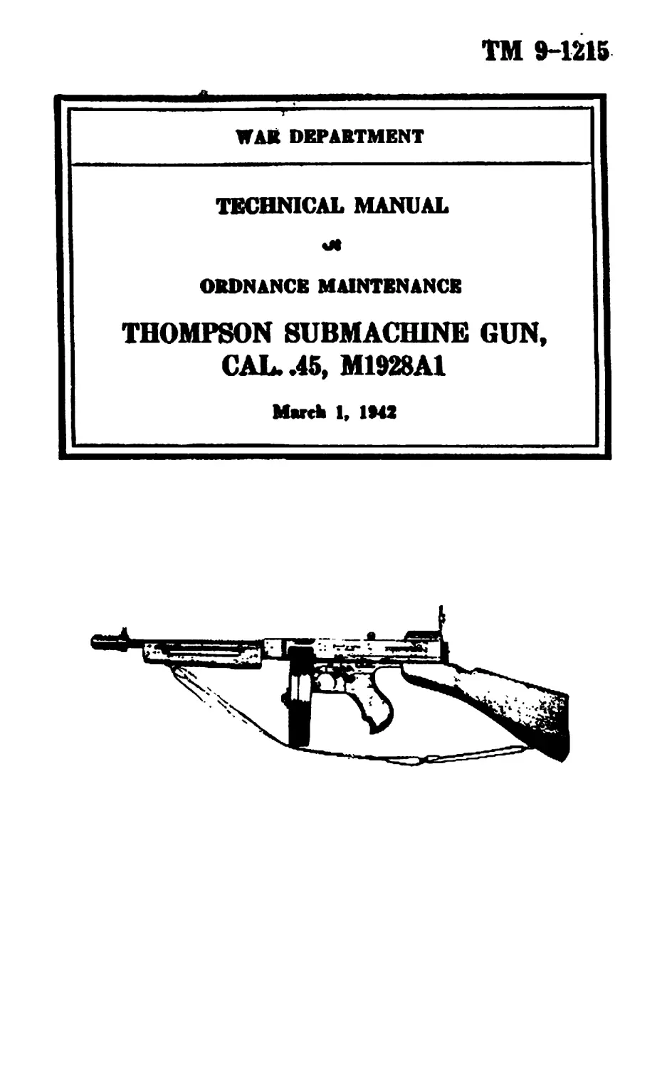
WAR DEPARTMENT
TECHNICAL MANUAL
ORDNANCE MAINTENANCE
THOMPSON SUBMACHINE GUN,
CAL. .45, M1928A1
Marek 1, IMS
TECHNICAL MANUAL
No. 9-1215
TM 9-1215
1-2
WAR DEPARTMENT,
Waahirgton, March 1, UM2.
ORDNANCE MAINTENANCE, THOMPSON SUBMACHINE
GUN, CAL. .45, M1928A1' “
Рге»аг«4 under directlMl •< *•
Clikf rtf ОгДпажсе
ГапчспфЬя
Section I. Introduction________________________ ________ 1
II. General description ________________________ 2 4
HI. Inspection---------- -------------------------- 5 12
IV. Maintenance and repair---------------------- . 13 18
V. References____________ ____________ - ------ 19-20
Pur*
Index to Text----------------------------------------------23-25
Section I
INTRODUCTION
ГягяЕгпрЬ
Scope------------------------------------------------ --- 1
1. Scope.—This manual is published for tbe information and
guidance of ordnance maintenance personnel. It contains detailed
instructions for ins)>ection, disassembly, assembly, maintenance, and
repair of the Thompson submachine gun, cat .45. M1928A1, sup-
plementary to those in the Field and Technical Manuals prepared for
the using arm. Additional descriptive matter and illustrations are
included to aid in providing a complete working knowledge of the
materiel.
Section II
GENERAL DESCRIPTION
РПГПГГЯ|*||
Description----------.----------------------------- __ --------------- 2
Mpchftniam--------------- -------—_____________________ . . ----- 3
Operation------------------------------------------- . ------ ----------- 4
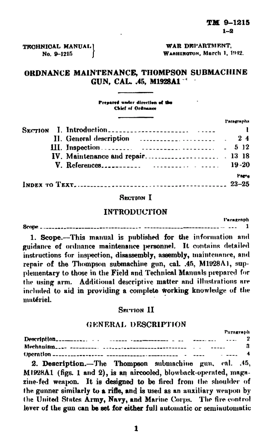
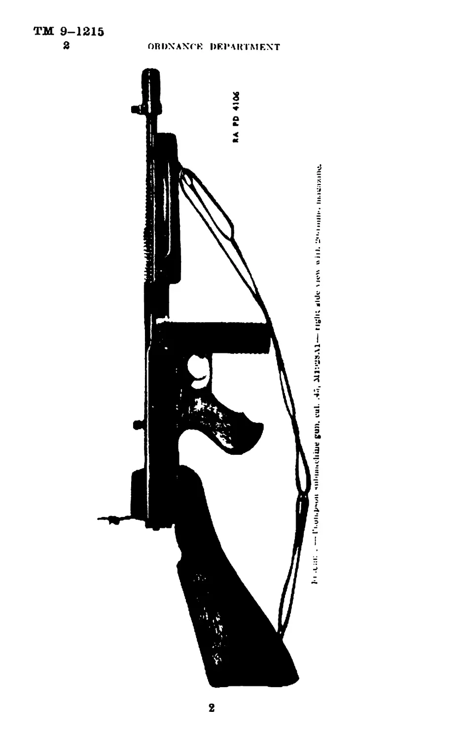
2. Description.—The Thompson submachine gun, cal. .45,
Ml928Al (figs. 1 and 2), is an aircooled, blowback-operated, maga-
zine-fed weapon. It is designed to be fired from the shoulder of
the gunner similarly to a rifle, and is used as an auxiliary weapon by
the Uniteci States Army, Navy, and Marine Corps. The fire control
lever of the gun can be set for either full automatic or semiautomatic
1
ТМ 9-1215
2
ОПЬХАХГЕ DEPAKTMEXT
2
ТМ 9-1
THOMPSON SURMACIHNR GUN 2
-ThotniMi
3
ТМ 9-1215
fc-4
ORDNANCE DEPARTMENT
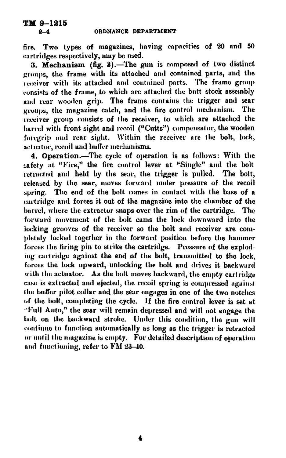
fire. Two types of magazines, having capacities of 20 and 50
cartridges respectively, may be used.
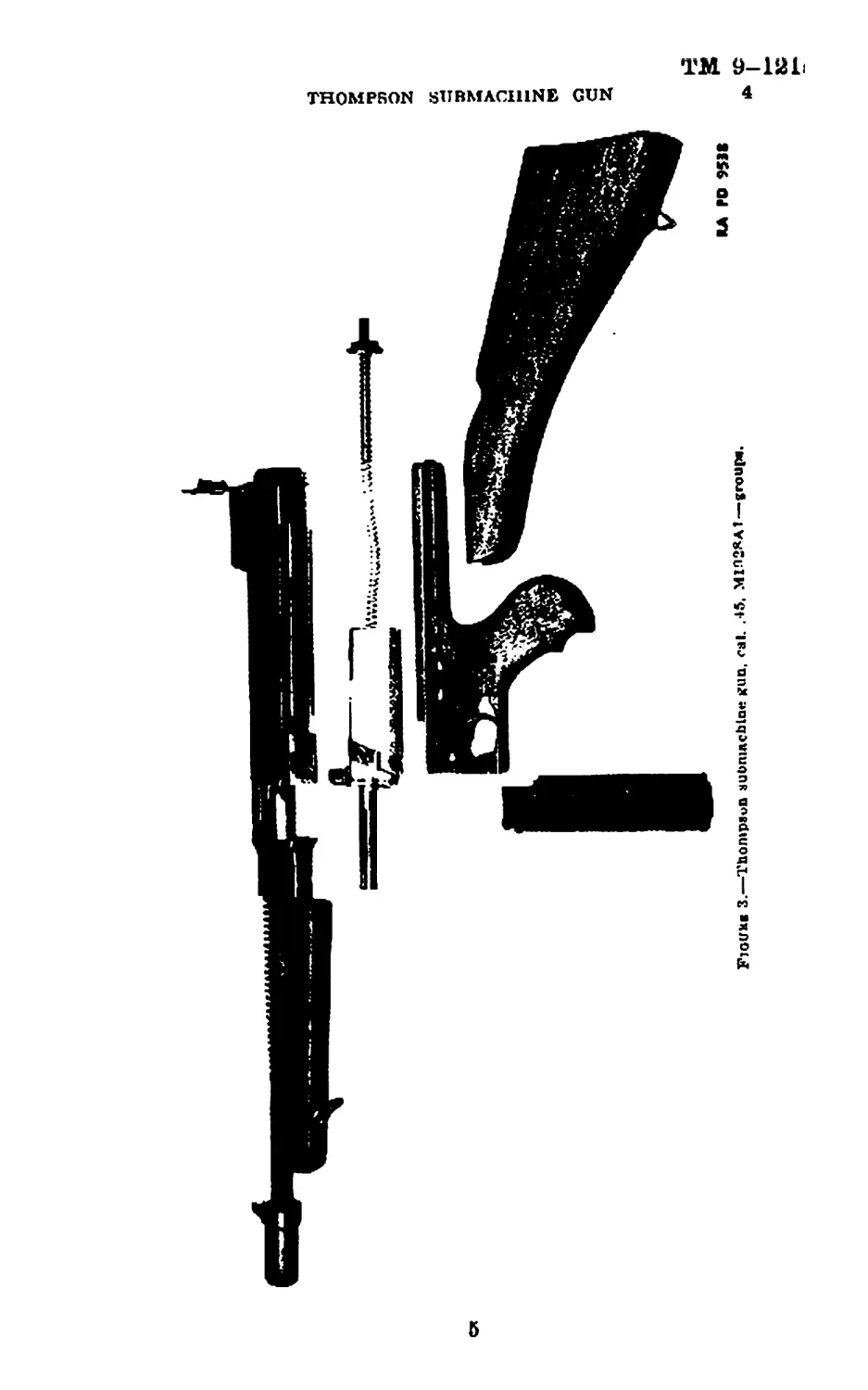
3. Mechanism (fig. 3).—The gun is composed of two distinct
groups, the frame with its attached and contained parts, and the
receiver with its attached and contained parts. The frame group
consists of the frame, to which arc attached the bntt stock assembly
and rear wooden grip. The frame contains the trigger and sear
groups, the magazine catch, and the firo control mechanism. The
receiver group consists of the receiver, to which are attached the
barrel with front sight and recoil (“Cutts”) compensator, the wooden
foregrip and rear sight. Within the receiver are the bolt, lock,
actuator, recoil and buffer mechanisms.
4. Operation.—The cycle of oi»eration is as follows: With the
safety at “Eire/’ the fire control lever at “Single” and the bolt
retracted and held by the sear, the trigger is pulled. The bolt,
released by the sear, moves forward under pressure of the recoil
spring. The end of the bolt comes in contact with the base of a
cartridge and forces it out of the magazine into the chamber of the
barrel, where the extractor snaps over the rim of the cartridge. The
forward movement of the Imlt cams the lock downward into the
locking grooves of the receiver so the bolt and receiver are com-
pletely locked together in the forward position l>eforc the hammer
forces the firing pin to strike the cartridge. Pressure of the explod-
ing cartridge against the end of the bolt, transmitted to the lock,
forces the luck upward, unlocking the bolt and drives it backward
with the actuator. As the bolt moves backward, the empty cartridge
case is extracted and ejected, the recoil spring is compressed against
the buffer pilot. collar and the sear engages in one of the two notches
of the l»olt, completing the cycle. If the fire control lever is set at
“Full Auto,” the scar will remain depressed and will not engage the
bolt on the backward stroke. Under this condition, the gun will
continue to function automatically as long as the trigger is retracted
or until the magazine is empty. For detailed description of operation
and functioning, refer to FM 23-40.
4
TM 9-12L
4
THOMPSON SUBMACHINE GUN
FjgUHb 3.—Thompson subniAcblQ** jfUQ, cal. .15. М1Л2ЯАТ—group*.
6
TM 9-1215
6-8 ORDNANCE DEPARTMENT
Section III
INSPECTION
Paragraph
General------------------------------------------------------------- 5
luspcd-lon report .... --- ..... ------------------- ----------------- 6
'ГпоЬ for jiibpectlon —.................... - - ---------------------- 7
(Jun as a unit----------------- ----------- ------------ ----------------- 8
Fruiuo group-------------------------------------------- --- . ----------- 9
Receiver and barrel groui»»— - ------------ ------------------------------ 10
Dox magazine______________________________________________________________ 11
Drum magazine - ... -- ... --- ------ 12
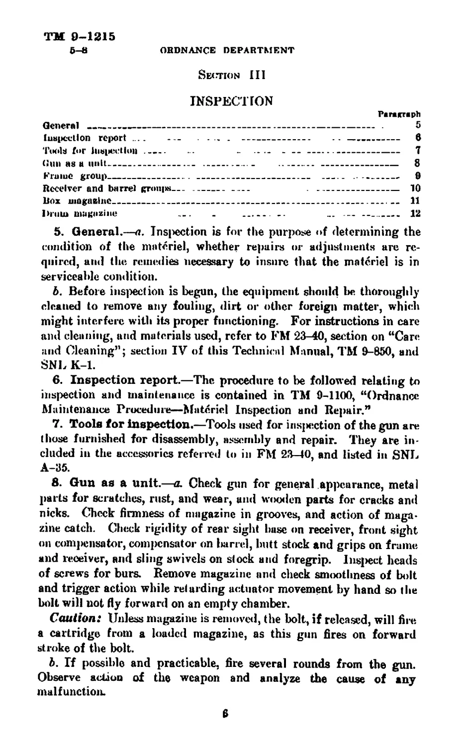
5. General.—л. Inspection is for the purpose <»f determining the
condition of the materiel, whether repairs or adjustments are re-
quired, and (he remedies necessary to insure that the materiel is in
serviceable condition.
b. Before inspection is begun, the equipment should be thoroughly
cleaned to remove any fouling, dirt or other foreign matter, which
might interfere with its proper functioning. For instructions in care
and cleaning, and materials used, refer to FM 23-40, setlion on “Care
and Cleaning”; section IV of this Technical Manual, TM 9-850, and
SNL K-l.
6. Inspection report.—The procedure to be followed relating to
inspection and maintenance is contained in TM 9-1100, “Ordnance
Maintenance Procedure—Materiel Inspection and Repair,”
7. Toole for inspection.—Tools used for bisection of the gun are
(hose furnished for disassembly, assembly and repair. They are in-
cluded in the accessories referred to in FM 23-40, and listed in SNL
A-35.
8. Gun as a unit.—a. Check gun for general appearance, metal
parts for scratches, rust, and wear, and wooden parts for cracks and
nicks. Check firmness of magazine in grooves, and action of maga»
zine catch. Check rigidity of rear sight base on receiver, front sight
on comjiensator, compensator on lairrel, butt stock and grips on frame
and receiver, and sling swivels on stock and foregrip. Insect heads
of screws for burs. Remove magazine and check smoothness of bolt
and trigger action while retarding actuator movement by hand so the
bolt will not fly forward on an empty chamber.
Caution: Unless magazine is removed, the bolt, if released, will fire
a cartridge from a loaded magazine, as this gun fires on forward
stroke of the bolt.
b. If possible and practicable, fire several rounds from the gun.
Observe action of the weapon and analyze the cause of any
malfunction.
9
THOMPSON SUBMACHINE GUN
ТМ 9-1215
0 ORDNANCE DEPARTMENT
9. Frame group.—a. To inspect the frame group, first remove the
butt stock assembly. Full the actuator to rear until the bolt is caught
ami held by the sear. With the bolt in rearward position, set the fire
control lever (rocker pivot) at “Full Auto” and the safety at “Fire”
and allow bolt to go forward slowly by pulling the trigger and retard-
ing the actuator by hand.
Caution: It is necessary that the fire control Icvcr and the safety
l>c set as described before withdrawing the frame from the receiver.
Otherwise the sear and rocker will not be depressed and serious damage
can result to the mechanism if the frame is moved under these
conditions.
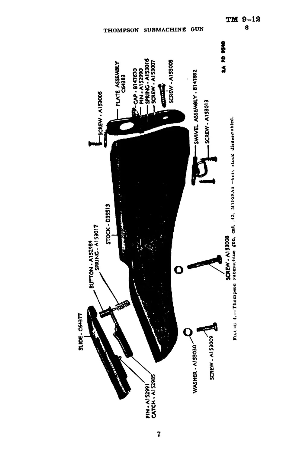
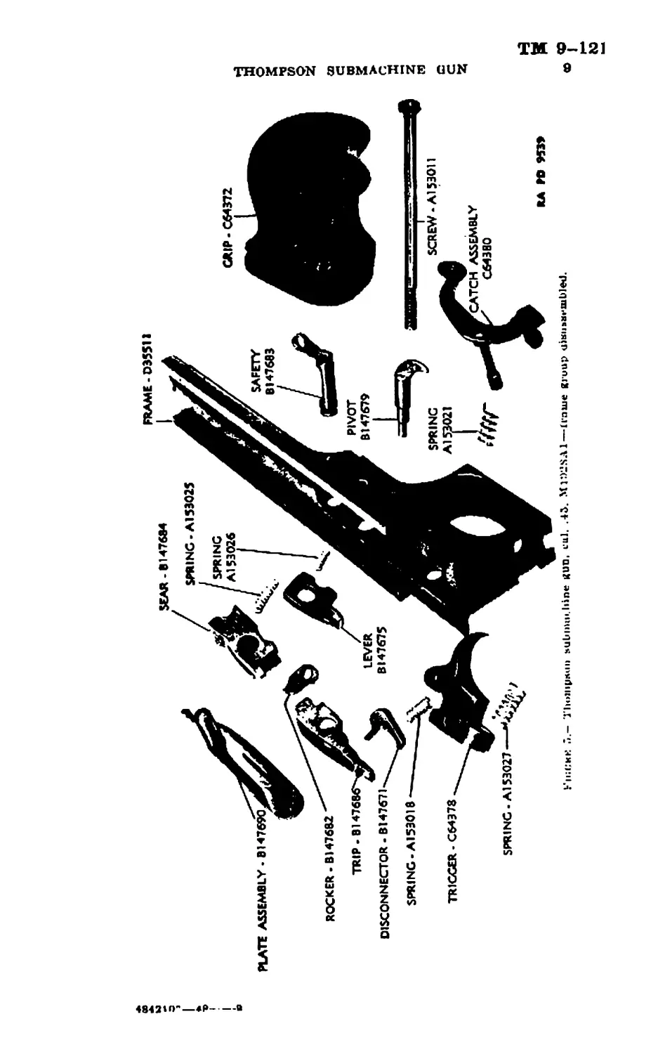
b. Butt stock assembly (fig. 4).—Check action of the butt stock
catch, and nose of catch for wear and burs. Remove the screws and
lift out the assembly. 1 nspect butt stock catch spring for functioning,
fracture and set. Free length of spring (A153017) is .75+.02 in.
Drive out the butt stock catchpin and remove catch. (To remove the
catch button, file pin to round and drive out.) Inspect the butt stock
slide for burs and dents. Remove the butt stock plate to inspect
action of trap spring. Tf necessary, remove the spring and drive out
trap pin. (The bracket is riveted to the butt plate.) Remove the
sling swivel screws and lift out the swivel plate. If necessary, spring
the swivel from the plate.
c. Brume (fig. 5).—Inspect the frame for cracks in the metal and
dents and burs on corners, grooves and surfaces of stock slideways and
magazine grip. Inspect the butt stock catch notch for wear and
burs. Inspect the safety and the pivot holes in the frame for wear.
If the rear grip is loose, inspect screw threads in frame and on screw
for wear, and the screw for straightness. Inspect the frame latch
notch in rear of frame for wear and burs.
d. Magazine catch, assembly.—Unless necessary, do not remove the
magazine catch from the frame as the spring is apt to be damaged.
If removed, check spring for functioning, fracture and set. Free
length of spring (A153021) is .85+.02 in. Look for foreign matter
in spring alwrture. Check movement of the magazine patch in the
frame without spring. Check the catch nose for wear and burs.
Check pin for wear and firmness in the latch. (Head of pin is riveted
into latch.)
e. Safety.—Check movement of the safety in the frame without
pivot plate. Inspect bearing surfaces for wear and burs.
/. Hocker.—Check movement of the rocker on rocker pivot Inspect
for wear and burs on contacting surfaces.
8
THOMPSON SUBMACHINE GUN
ТМ 9-1215
9-10
ORDNANCE DEPARTMENT
g. Rocker pvvot.—Check movement of the rocker pivot in the frame
without pivot plate. Inspect liearing surfaces for wear and burs.
Л. Pivot plate assembly.—Check the pivot pl ale short and long
springs for functioning, fracture, and set. Inspect pivot pins for
wear and firmness in the plate. (Pin heads are riveted into plate.)
i. Sear group (fig. 5).—Check sear for retention of the bolt. Ins[>ect
the sear fur wear and bill's on nose and contracting surfaces, and for
foreign mailer in spring aperture. Check movement of the scar with
sear lever on the pivot. Check sear spring for functioning, fracture,
and set. Free length of spring (A153025) is .765 I .02 in. Inspect
scar lever for wear and burs on contacting surfaces and for foreign
matter in spring aperture. Check sear lever spring for functioning,
fracture, and set. Free length of spring (A 153026) is .43^-.01 in.
j. Trigger group (fig. 5).—Inspect the trigger for wear in pivot
hole and disconnector pivot hole, and for deformation of tip. Check
action of trigger with disconnector and trip on trigger pivot. Check
trigger spring for functioning, fracture, and set. Free length of
spring (A153027) is .65^.01 in. Inspect disconnector for wear on
pin and wear and burs on contacting surface. Check disconnector
spring for functioning, fracture, and set Free length of spring
(A153018) is .50^:.01 in. Inspect trip for wear and burs on contacting
surfaces.
k. Assemble the sear and trigger mechanisms in the frame and try
action of the trigger with the rocker in each position.
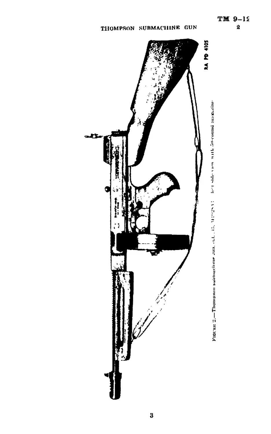
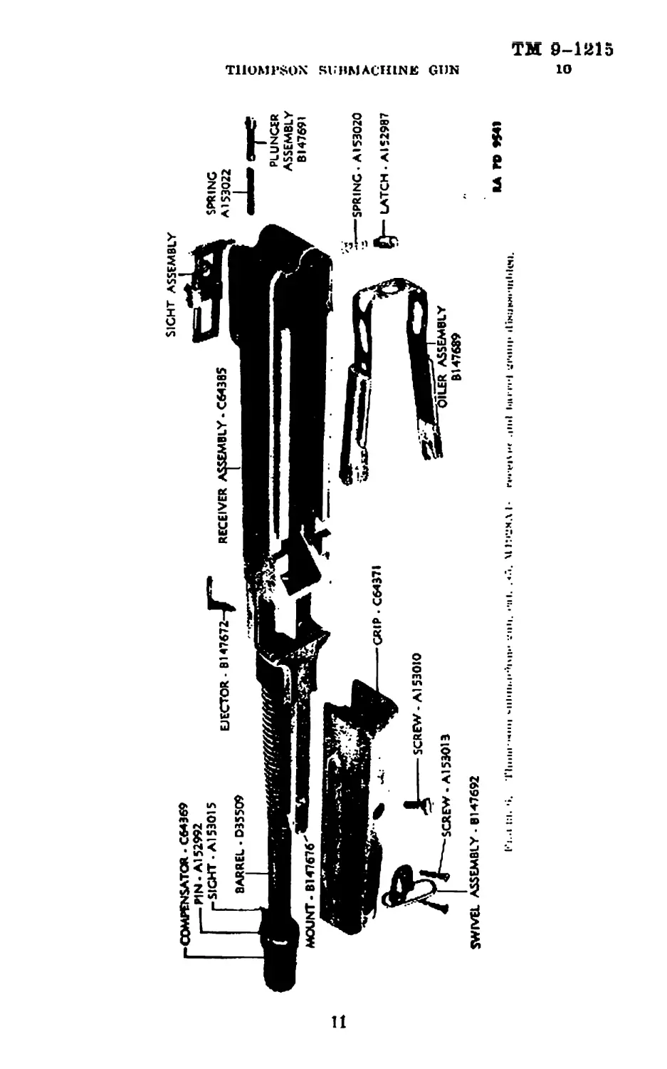
10. Receiver and barrel groups (fig. 6).—a. To inspect the
rweiver group, remove the buffer pilot and pad together with the
recoil spring from the receiver. With the receiver inverted, move the
nd uator back and forth to insfiect movement of the lock in the
grooves of receiver and bolt. Take out the bolt group, actuator and
luck, and remove oiler assembly.
b. Receiver group.—lns|>ect the receiver for wear and burs on
frame slideways and lock camming surfaces, and the bullet ramp for
wear and fouling. Inspect corners and edges for dents and burs and
the. magazine retaining grooves and actuator groove for wear. Inspect
the buffer pilot aperture for wear. Inspect the frame latch for wear
and aperture for wear and foreign matter. Cheek latch spring
for functioning, fracture, and set. Free length of spring (A153020)
is .45.L.01 in. Check the ejector for firmness in receiver, and inspect
the point for wear and alinement. Never try to remove the ejector
from receiver with the Imlt in the forward position.
c. Barrel group.—Inspect the barrel as a unit from the standpoint
of serviceability.
Ю
rC0MFENSATC3R - С64369
.------PIN* Al52992
pSIGHT- Al53015
BARREL > 035509
EJECTOR - Bl 47672-
IBLY-C6438S
SIGHT ASSEMBLY
SPRING
A153022
i t:i. 'к Tliiiui• ".ini <-и111и.H’»|»ij.' •••UH. ••ill. . «й. \11:»2МД I- !•»•••
PLUNGER
ASSEMBLY
BI47691
THOMPSON SUBMACHINE GUN
ТМ 9-121Б
10 ORDNANCE DEPARTMENT
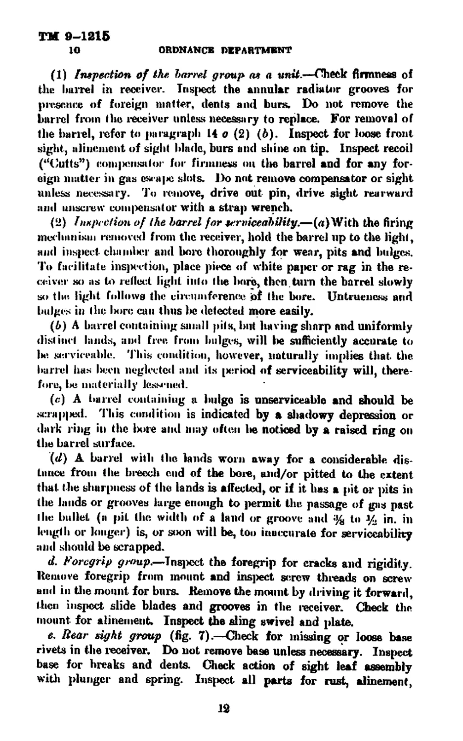
(1) inspection of the barrel group as a unit.—Check firmness of
tlie barrel in receiver. Inspect the annular radiator grooves for
presence of foreign matter, dents and burs. Do not remove the
barrel from the receiver unless necessary to replace. For removal of
the barrel, refer to paragraph 14 о (2) (b). Inspect for loose front
sight, alincnicnt of sight blade, burs and shine on tip. Inspect recoil
(“Cults”) com] юная I or for firmness on Hie barrel and for any for-
eign matter in gas с* а|м> slots. Do not remove compensator or sight
unless necessary. To remove, drive out pin, drive sight rearward
and unscrew coni|Mjnsator with a strap wrench.
(2) Inspection of the barrel for serviceability.—(л)With the firing
median ism reniovid from the receiver, hold the barrel up to the light,
and inspect din inlier and bore thoroughly for wear, pits and bulges.
To fac ilitate insertion, place piece of white pajicr or rag in the re-
ceiver so as to reflect light into I lie boro, then, turn the barrel slowly
so the light follows the circumference of the bore. Un true n ess and
bulges in the 1югс can thus lie detected more easily.
(6) A barrel containing small pits, but having sharp and uniformly
distinc t lands, and free from bulges, will lie sufficiently accurate to
lie serviceable. This condition, however, naturally implies that the
barrel has lieen neglected and its [icriod of serviceability will, there-
fore, Ixi materially lessened.
(<;) A barrel containing a bulge is unserviceable and should be
scrap|MMl. This condition is indicated by a shadowy depression or
dark ring in the bore and may often lie noticed by a raised ring on
the barrel surface.
(d) A band with the lands worn away for a considerable dis-
tance from the bi-eech end of the bore, and/or pitted to the extent
that the sharpness of the lands is affected, or if it has a pit or pits in
the lands or grooves large enough to permit the passage of gas past
the bullet (a pit the width of a land or gnx>vc and % to % in. in
length or longer) is, or soon will be, too inaccurate for serviceability
and should be scrapped.
d. Foregrip group.—Inspect the foregrip for cracks and rigidity.
Remove foregrip from mount and inspect screw threads on screw
and in the mount for burs. Remove the mount by driving it forward,
then inspect slide blades and grooves in the receiver. Check the
mount for alinemeut» Inspect the sling swivel and plate.
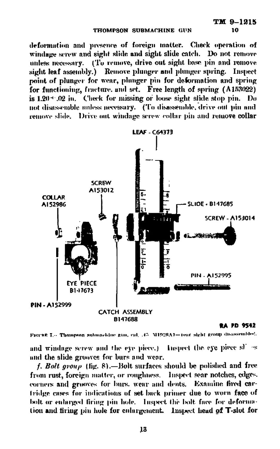
e. Rear sight group (fig. 7).—Check for missing or loose base
rivets in the receiver. Do not remove base unless necessary. Inspect
base for breaks and dents. Check action of sight leaf assembly
with plunger and spring. Insjwct all parts for rust, alinement,
12
TM 9-1215
10
THOMPSON SUBMACHINE GUN
deformation and presence of foreign matter. Check operation of
windage screw and sight slide and sight slide catch. Do not remove
unless necessary. (Tu remove, drive out sight l>ase pin and remove
sight leaf assembly.) Remove plunger and plunger spring. Inspect
point of plunger for wear, plunger pin for deformation and Spring
for functioning, fracture. and set. Free length of spring (Л153022)
is 1.20 4 .02 in. Chirk for missing or loose sight slide stop pin. Do
not disassemble unless necessary. (To disassemble, drive old pin nnd
remove slide. Drive out windage screw collar pin and remove collar
LEAF - C64373
PIN-Al 52999
CATCH ASSEMBLY
BM7688
*A RD 9542
FicrftR 7... Thompson я«|Ь1нл«‘Ь|п<* £1111, 1-al. .<"• М1ГК2ЯЛ1—IvsiC RHHip ilikiixsirinlih*!.
and windage screw and the eye piece.) Inspect (he eye piece si *s
and die slide greaves for burs and wear.
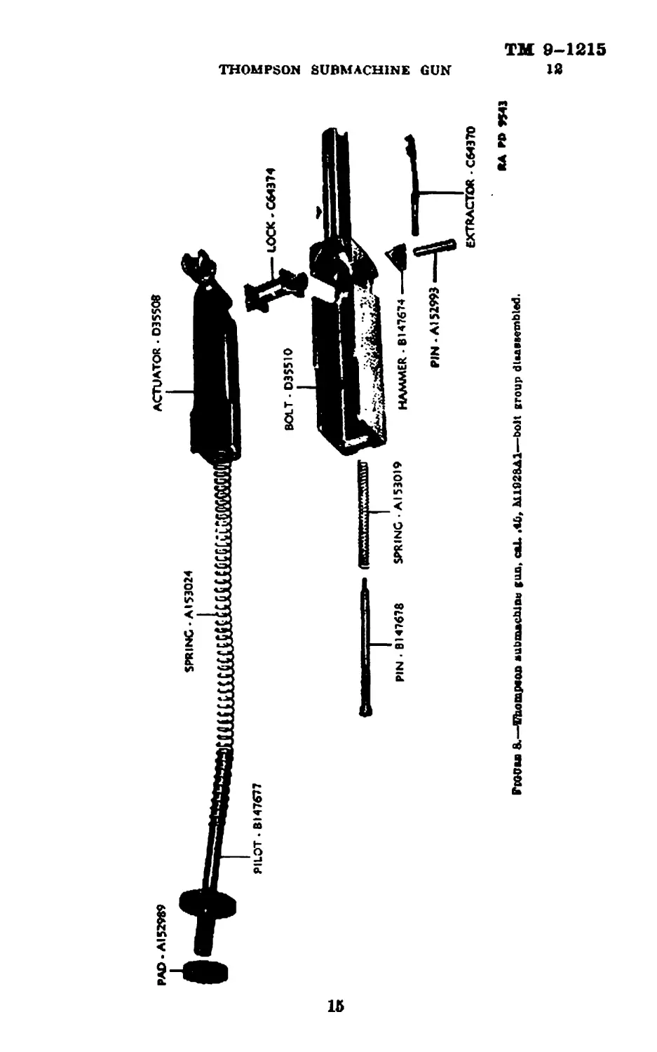
/. Bolt group (lig. 8).—Dolt surfaces should be polished and free
from rust, foreign matter, or nmgbness. Insert sear notches, edges,
corners and grooves for Imrs. wear and dents. Examine tired car-
hidge cases for indications of set back primer due to worn face of
bdt or enlarged tiring pin hole. InsjMft Ihi' Irnlt fnre for deforma-
tion and tiring pin hole for enlargement Inspect head of T-slut for
13
ТМ 9-1215
10-12 ORDNANCE DEPARTMENT
burs and wear caused by the rocker. Remove the extractor, taking
care not to spring moi-e than necessary to dear the lug. Inspect
the extractor for set and deformation, anil daw for wear. Remove
the hammer pin, hammer, firing pin and firing pin spring. Check
hammer pin for looseness and wear. Check hammer for wear and
burs in pin hole and on contacting surfaces. Inspect firing pin
head and nose for wear and burs. Check firing pin spring for
functioning, fracture, and set. Free length of spring (A 153019) is
2.50 4-.05 in.
g. Lock.—Inspect lock for wear and burs on sliding surfaces.
Check movement of lock in nchialor and reeeiver locking grooves.
Л. Actuator- Insjiei't actuator for wear and bin’s on sliding sur-
faces, recoil spring aperture for foreign matter and actuator head
for fracture or deformation.
i. Buffer group.—Inspect buffer pilot for alinement, deformation,
and wear. Tiis|mh4 buffer pad for deformation and wear.
j. Oiler group - Check oiler fur lit and spring retention in receiver.
Sides of oiler should lie flush to sides of receiver. Check oiler pads
for fraying and absorption.
k. liecoil apriug.—Inspect recoil spring for functioning, deforma-
tion, fracture, and set. Free length of spring (A 1.53024) is 10.004-.25
in. ('are must lie taken in removing and replacing this spring, as it
is apt to fly loose and become twisted lietwi’cn actuator and pilot,
resulting in deformation which may cause binding on compression
stroke, of lx)lt.
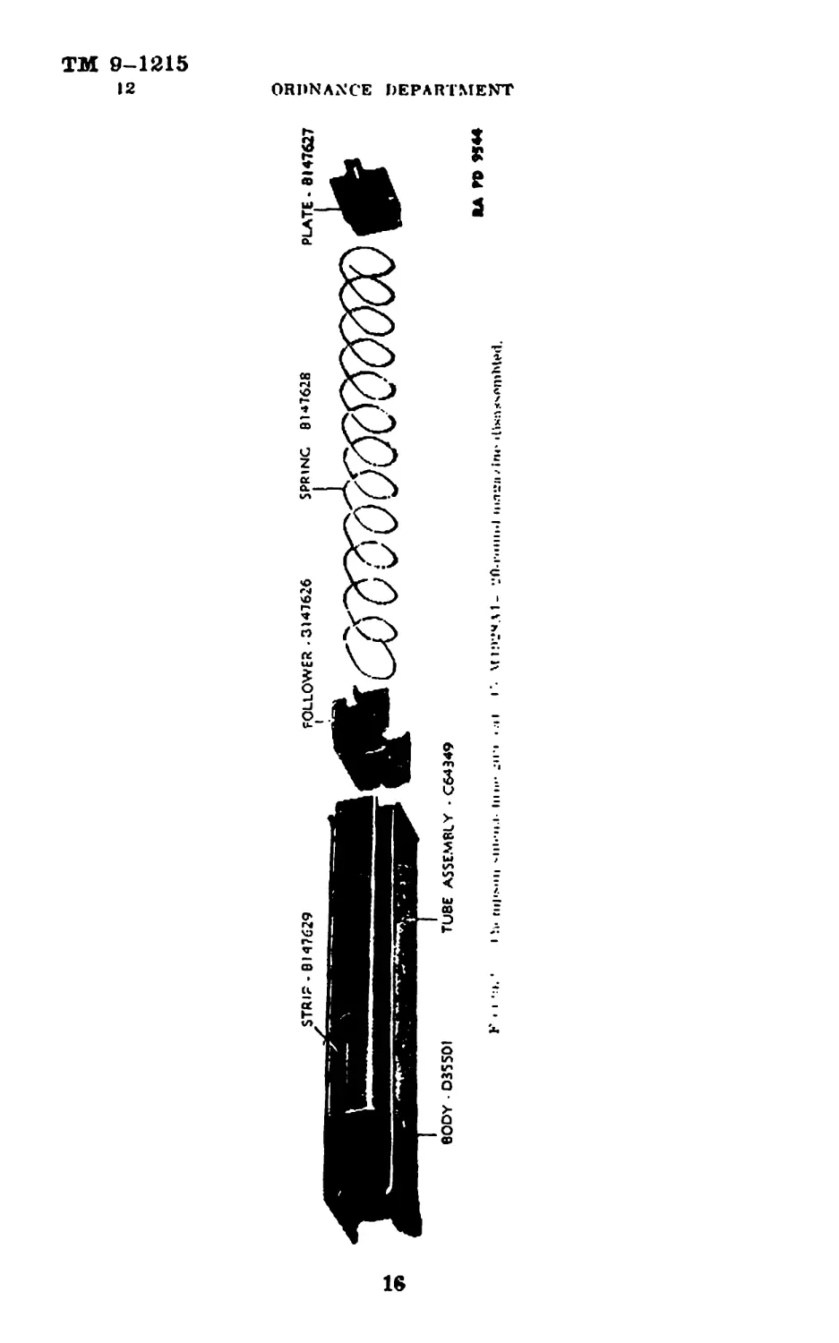
11. Box magazine (20 rounds) (tig.!»i.—ч. (’hock box magazine,
for fit and retention in receiver.
b. Depress follower and note smoothness of oblation and tension
of spring. Insert two or th ire dummy cartridges in magazine nnd
attach magazine to gun. Operate the piece by hand and observe
loading, extraction, and ejection. Note also whether the magazine
follower (when the magazine is empty) lifts the trip sufficiently to
force the disconnector from under the scar lever and allow the sear
to catch the bolt and hold it in the open position.
c. Inspect magazine tube for dents, cracks, deformed lips, and for-
eign matter. Check follower pin for deformation, wear and burs, ami
magazine spring for functioning, fracture, and set. Free length
of spring is 8.004- .20 in.
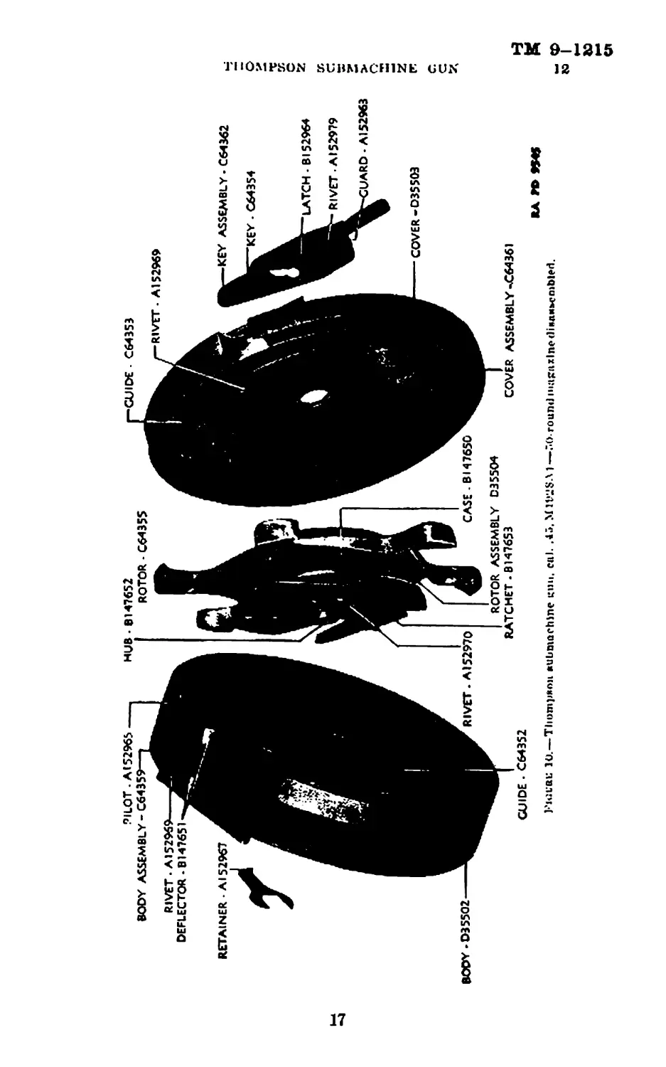
12. Drum magazine (50 rounds) (fig. 10).—a. Check drum
magazine for fit and retention in receiver.
b. Remove winding key and note its condition. Remove cover and
check cover guide, slide and rivets. Rotate the rotor, noting the
14
TM 9-1215
THOMPSON SUBMACHINE GUN 18
ACTUATOR • 035508
15
TM 9-1215
12
ORDNANCE DEPARTMENT
16
THOMPSON SUBMACHINE GUN
ТМ 9-1215
12—14 ORDNANCE DEPARTMENT
action of the rotor spring. Further test the magazine by forcing the
finger of the rotor standing nearest the feedway in the opposite di-
rection to its normal rotation, and insert five dummy cartridges (one
resting in the feedway). Replace cover and winding key and increase
tension of rotor spring by turning the winding key one click. Insert
the magazine and operate the piece rapidly by hand and observe
loading, extraction, and ejection.
<?• Inspect magazine body and cover for deformation and dents.
Check guides in cover and Ixxly for deformation, and deflector for
looseness and wear. Check key and retainer for deformation, and
magazine catch grip in body for deformation and bin's. Do not
disassemble rotor and spring case unless necessaiy, as they are riveted
together.
Section IV
MAINTENANCE AND REPAIR
Pur* graph
General-------------- ------------------------------------------------- —- 13
Inalructiona for mnlutrnunce and repair------------------------- ----- ---- J4
Care and cleaning---- ------ ------- -------- .. .........................- 15
Care and denning In Arctic climates------- ----- -------------- -------- 16
Lubrication---------------------------------------------- ------ ------— 17
Мя(6г1е1 affpclrd hy gas----------------------------. ------------- ------- 18
13. General.—o. The maintenance and repair of the Thomson
submachine gun, cal. .45, M1928A1, as covered in this manual is
primarily a replacement of worn or broken |>arts. General disassem-
bly and assembly of the gun is covered in FM 23-40.
b. Where parts, assemblies, or parts of assemblies are broken or
worn so as to render them unserviceable, they must be replaced from
stock. Often only parts of assemblies will lie broken or worn; where
it will take more time to remove the serviceable parts from the assent
bly than the parts are worth, the assembly should be scrapped. Parts
do not always interchange and should be assembled by selection.
c. In general, maintenance operations are of n first aid nature, per
formed by qualified ordnance personnel with only the limited to<»|
facilities afforded by repair trucks, or by semipermanent shops at
posts or camps, or by an inspector wlrile making a regular inspection.
14. Instructions for maintenance and repair.—a. Burs on
fcrews and smooth surfaces.—Remove burs from screw heads, threads
and like surfaces with я fine file, and chase out damaged threads with
a die if available. Remove the burs from smooth contacting surfaces
with a fine grained shaqxming stone or emery cloth, and finish with
crocus cloth. Polish rounded contacting surfaces with crocus cloth.
Care should be observed to file and stone evenly and lightly, removing
18
TM 9-1215
14
THOMPSON SUBMACHINE GUN
no more metal than is necessary. For materials employed in remov-
ing rust, cleaning and preserving, and the limits of their proper use,
refer to TM 9-850.
b. Frame group.—(1) Butt stock, assembly,—If the butt stock is
not held rigidly to the frame by the slido or catch, the faulty parts
should be replaced.
(2) Frame.—When the frame is damaged to tl>e extent that inr
proper functioning of the gun results, it should be replaced.
(3) Magazine, catch, assembly.—If the magazine catch does not
hold in magazine firmly, it should lie replaced. Check to see if the
fault liee in the magazine.
(4) Rocker and rocker pivot.—The nicker or rocker pivot should
lie replaced if worn to the extent, that automatic firing occurs with the
rocker pivot set at “Single.”
(5) Scar, trigger and pivot plate groups,—{a) When the bearing
surfaces on the scar, trigger and the pivot plate pins become worn
to the extent that malfunctioning of the gun results, the worn part or
parts should be replaced.
(b) If either spring finger on the pivot plate becomes set or broken,
replace the pivot plate.
c. Receiver and barrel, groups.—(1) Receiver group.—(a) A re-
ceiver damaged to the extent that malfunctioning of the gun results
should be replaced.
(b) A worn ejector should be replaced.
(a) If the frame latch or aperture liecomes worn so that the frame
is not securely locked to the receiver, the latch or receiver should be
replaced.
(2) Barrel group,—(a) If it is determined that the barrel is un-
serviceable by ins]M*ction as prescrilied in paragraph 10 c (2), the
barrel should l>c replaced.
(6) To remove band, disassemble the gun, wedge a block of hard
wood in receiver to prevent springing of the side, clamp receiver in a
vise with leather jaws and unscrew' barrel from receiver, using a strap
wrench. If barrel is to be scrapped, a pipe wrench may be used.
(c) When it is determined to replace the barrel, the recoil com-
pensator and front sight, if in good condition, should be removed
from the defective barrel for assembly to the new barrel.
(8) Rear sight group.—If the rear sight has been broken or bent
out of line, tlia damaged parts or the entire leaf assembly should be
^placed.
(4) Bolt group.—(a) If the face of the bolt shows signs of wear,
or firing pin hole has become enlarged, the bolt should be replaced.
19
TM 9-1215
14—17
ORDNANCE DEPARTMENT
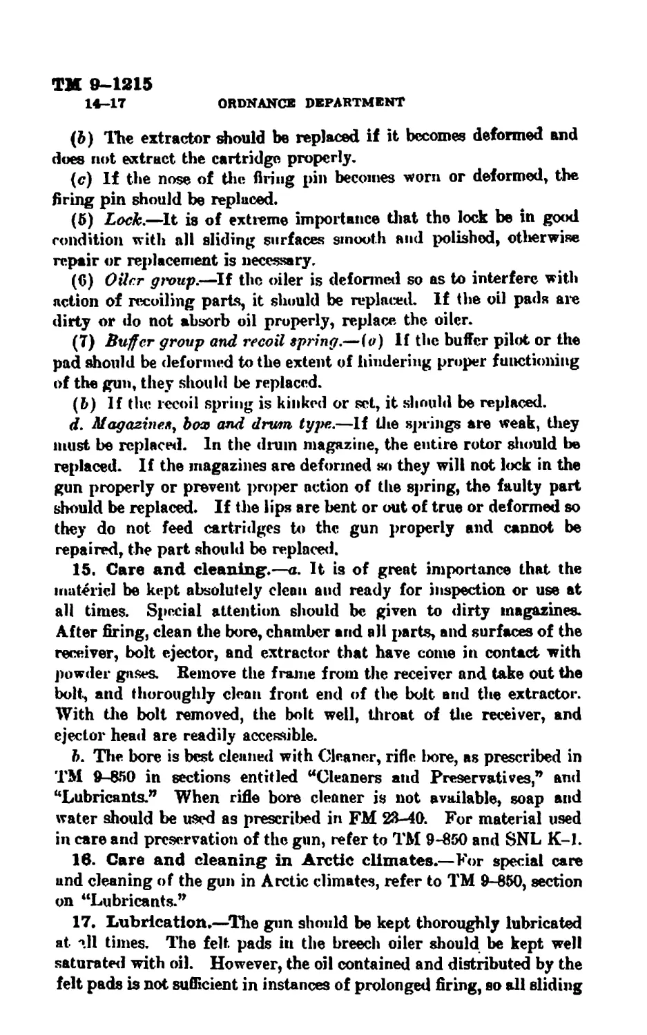
(&) The extractor should be replaced if it becomes deformed and
does not extract the cartridge properly.
(c) If the nose of the firing pin becomes worn or deformed, the
firing pin should be replaced.
(5) Lock.—It is of extreme importance that the lock be in good
condition with all sliding surfaces smooth and polished, otherwise
repair or replacement is necessary.
(6) Oiler group.—If the oiler is deformed so as to interfere with
action of recoiling parts, it should be replaced. If the oil pads are
dirty or do not absorb oil properly, replace the oiler.
(7) Buffer group and recoil spring.—(o) If the buffer pilot or the
pad should be deformed to the extent of hindering proper functioning
of the gun, they should be replaced.
(l>) If the recoil spring is kinked or set, it should be replaced.
rf. Magazines, box and drum type.—If the springs are weak, they
must be replaced. In the drum magazine, the entire rotor should be
replaced. If the magazines are deformed so they will not lock in the
gun properly or prevent proper action of the spring, the faulty part
should be replaced. If the lips are bent or out of true or deformed so
they do not feed cartridges to the gun properly and cannot be
repaired, the part should be replaced.
15. Care and cleaning.—a. It is of great importance that the
materiel be kept absolutely dean and ready for inspection or use at
all times. Special attention should be given to dirty magazines.
After firing, clean the bore, chamber and all parts, and surfaces of the
receiver, bolt ejector, and extractor that have come in contact with
powder gases. Remove the frame from the receiver and take out the
bolt-, and thoroughly dean front end of the bolt and the extractor.
With the bolt removed, the bolt well, throat of the receiver, and
ejector head are readily accessible.
6. The bore is best cleaned with Cleaner, rifle 1юге, as prescribed in
TM 9-850 in sections entitled “Cleaners and Preservatives,” and
“Lubricants.” When rifle bore cleaner is not available, soap and
water should be used as prescribed in FM 23-40. For material used
in care and preservation of the gun, refer to TM 9-850 and SNL K-L
16. Care and cleaning in Arctic climates.—For special care
and cleaning of the gun in Arctic climates, refer to TM 9-850, section
on “Lubricants.”
17. Lubrication.—The gun should be kept thoroughly lubricated
at Ml times. The felt, pads in the breech oiler should be kept well
saturated with oil. However, the oil contained and distributed by the
felt pads is not sufficient in instances of prolonged firing, so all sliding
TM 9-1215
THOMPSON SUBMACHINE OWN 17-20
surfaces should be oiled frequently and freely to insure perfect func-
tioning of the gun. For pro])er instruction in the lubricating of the
gun, refer to FM 23-40, and for material used, TM 9-850 and
SNLK-1.
18. Matfiriel affected by gas.—For defense against chemical
attack, and for procedure to be followed in the care of materiel
affected by gas, refer to FM 21-40 and TM 9-850.
Section V
REFERENCES
Paragraph
Standard Nnmend.iturp Lists------------------------------------- 1»
Explanatory puhilcalhniK________________________________________ 20
19. Standard Nomenclature Lists.
a. Ammunition, revolver я nd automatic pistol_____SNL T-2
b. Cleaning and yrt'Kcrring.
Cleaning, preserving and lubricating material,
recoil fluids, special oils, and similar items
of issue______________________________________ SNL K-l
Soldering, brazing, and welding materials, and
related items__________________________ _ ---- SNL K-2
c. Gun materiel.
Gun, submarine, cal. .45, Thompson, M1928AL SNL A-32
Tools, special repair, automatic guns, automatic
gun materiel, automatic and semiautomatic
cannon and mortars________________________ SNL A-35
Truck, small arms, repair, Ml_______________ SNL G-72
Current Standard Nomenclature Lists are as
tabulated here. An up-to-date list of SNL’s
is maintained as the “Ordnance Publications
for Supply Index'1________________________ OPSI
20. Explanatory publications.
a. Ammunition, generaL__________________________TM 9 1900
6. Cleaning, preserving, lubricating, and welding
materials, and similar items issued by the
Ordnance Department_________________________ TM 9-850
c. Gun materiel.
Defense against chemical attack________________FM 21-40
Ordnance maintenance procedure—Materiel
inspection and repair_______________________ TM 9-1100
Thompson submachine gun, cal. .45, M1928A1.. FM 23-40
21
INPEX TO TEXT
A
Pace
Actuator, inspection of........... 14
Arctic climates, care of gun in. _. 20
В
Barrel, how to remove—........... 19
Barrel group:
illustrated disassembled_______ 11
inspection of . 12
maintenance and repair of._ 19
Bolt group:
illustrated disassembled ... 15
inspection of.... 13
maintenance and repair of.. 19
Bore, cleaning of........ .... 20
Box magazine (20 rounds):
illustrated:
attached to gun............ 2
disassembled.... .. 16
inspection of............-- 14
maintenance and re|>air of . 20
tube, inspection of. . ._ 14
Buffer group:
inspection of................. 14
maintenance and repair of... 20
Bulge in barrel................... 12
Burs, removing from smooth
surfaces...................... 18
Butt stock assembly:
illustrated disassembled___ 7
inspection of..... 8
maintenance and repair of.. 19
C
Care of gun . 20
Cleaner, rifle Imre............... 20
Cleaning of gun....... 20
Compensator, "Cutts":
assembly of to new barrel__ 19
removing..................... 12
D
Drum magasine (50 rounds):
illustrated:
attached to gun---------------- 3
disassembled__________ 17
Drum magasine—Continued. Рдг>
inspection of................ 14
maintenance and repair of. _ 20
rotor.... , ................. 14
spring case...............— 18
F.
50-round magasine (see Drum
magazine).
Fi re control lever, setting__ 1
Foregrip group, inspection of. . _ 12
Frame:
inspection of................... 8
maintenance and repair of.. 19
Frame group:
caution in disassembling--- 8
iUust rated disassembled.__ 9
inspection of.................. 8
maintenance and repair of... 19
parts composed of-.........- 19
Front sight, assembly of to new
barrel__________________________ 19
G
Gas, materiel affected by------ 21
Groni», gun assembly divided:
into.......... 4
illustrated .................. 5
I
Inspection of gun.............— 6
actuator....................... 14
barrel group................... 12
bolt group. ................... 13
box magazine .... ... 14
buffer group................... 14
buttstock assembly............. 8
drum magazine.................. 14
foregrip group. ............... 12
frame_________________________ 8
frame group.. ---------------- 8
gun as unit................... 6
lock___________________________ 14
magazines...................... 14
magazine catch assembly — 8
oiler group-------------------- 14
pivot plate assembly------ Ю
23
INDEX TO TEXT
Inspection of gun—Cont Inned.
purpose of..................... 6
rear sight group........... 12
receiver group....----------- 10
recoil spring................ 14
report on....................... 6
rocker........._.............. 8
rocker pivot................ 10
safety........................ 8
eear group..................... 10
tools for.................... 6
trigger group_________________ 10
L
Lands, worn....................... 12
Lock:
inspection <»f ........ ... 14
maintenance and repair of.. 20
Imbrication of gun............... 20
M
Magazine, types of ............... 4
box (are Box magazine),
drum (zee Drum magazine).
Magazine body, inspection of___ 18
Magazine catch assembly:
inspection of__________________ 8
maintenance and repair of._ 19
Magazine tulx? (box magazine),
inspection of_........... .... 14
Maintenance and repair of gun.. 18
barrel group...... 19
bolt group.................. 19
buffergroup................. 20
butt stock assembly-------- 19
drum magazine.-............ 20
frame________________________ 19
frame group_________________ 19
lock... ................... 20
magazine..................... 20
oiler group.................. 20
pivot plate assembly------- 19
rear sight group............. 19
receiver group............... 19
recoil spring.... ........... 20
rocker.... 19
rocker pivot ................ 19
sear group... .... 19
trigger group... 19
Mechanism of gun, described___ 4
Раде
О
Oiler group:
inspection of----------------- 14
maintenance and repair of_. 20
Operation of gun, described----- 4
P
Farts, gun, when to replace----- 18
Pits in barrel. . ................ 12
Pivot plate assembly:
inRjx?ction of................ 10
maintenance and repair of.. 19
Primer, set back, causes of----- 13
R
Rear sight group:
illustrated disassembled_______ 13
ins)»crtioii of.............. 12
maintenance and repair of.. 19
Receiver group:
illustrated disassembled______ II
inspection of.. ____________ 10
maintenance and rv|>air of__ 19
parts e<tiu|H>.-«(<d of..... 4
Recoil spring:
inspection of................ 14
maintenance and rejmir of__ 20
removing and replacing.____ 14
Repair of gun (see Maintenance
and repair of gun).
Rocker:
inspection of................. 8
maintenance and repair of_. 19
Rocker pivot:
inspection of.. ......... 10
maintenance and rejiair of— 19
Rotor, and spring case, disas-
sembling......................... 14
S
Safety, inspection of.. ____________ 8
Screws, removing burs from______ 18
Sear group:
illustrated........_.......... 9
inspection of______________ 10
maintenance and repair of-. 19
Serviceability, inspection of bar-
rel for..............—...........- 12
24
INDEX TO TEXT
Pate
Sight leaf assembly, removing
and disassembling_______________ 13
Sight slide and catch, removing. 13
Soap and water, use of in clean-
ing........................... 20
Spring case, and rotor, disassem-
bling.......................... IS
T
Thompson submachine gun, cal.
.45, M1928A1:
care and cleaning of......... 20
description of--------------- I
gas, affected by____________ 21
Thompson submachine gun—Oon. Pate
illustrated......................... 2, 3
inspection of.................. 6
lubrication of...........— 20
maintenance pnd repair of.. 18
mechanism of _ _ _............. 4
operation of.................. 4
Trigger group:
illustrated_____________________ 9
inspection of............-- 10
maintenance and repair of.. 19
20-round magasine (see Box
magasine).
W
Windage screw, removing________ 13
[A. G 042 11 (12-23-411.)
By order of the Secretary of Wab ;
G. c. MARSHALL,
Chief of Staff»
Official :
E. S. ADAMS,
Major General,
The Adjutant General.
Diotribution; Bn 9 (1); IC 9 (3).
(For explanation of symbols see FM 21-6.)
.«.«mi'MtvT иижли» emce.ilet
25