/


Теги: weapons military affairs machine gun
Год: 1943


Текст
ТМ 9-224
WAR DEPARTMENT
TECHNICAL MANUAL
MACHINE GUN MOUNTS
FOR TRUCKS
APRIL 22, 1943
ТМ 9-224
TECHNICAL MANUAL WAR DEPARTMENT
No. 9-224 Washington, April 22, 1943
MACHINE GUN MOUNTS FOR TRUCKS
Prepared under the direction of the
Chief of Ordnance
CONTENTS
Paragraphs Pages
Section I. Introduction 1-3 2-11
II. Operation 4 12
III. Mounting and dismounting weapons 5- 8 13-28
IV. Disassembly and assembly........ 9-11 29-30
V. Care and preservation ............ 12—19 31-33
VI. Inspection 20-21 34-35
VII. Maintenance and repair............ 22—24 36—41
VIII. Painting 25-29 42-44
IX. References 30-31 45
Index 46- 48
1
ТМ 9-224
1-2
MACHINE GUN MOUNTS FOR TRUCKS
Section I
INTRODUCTION
Paragroph
Scope............................... . 1
Description and characteristics 2
Differences among models . 3
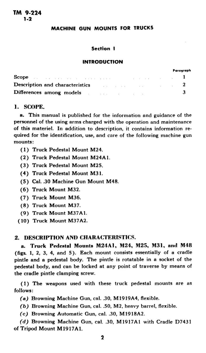
1. SCOPE.
a. This manual is published for the information and guidance of the
personnel of the using arms charged with the operation and maintenance
of this materiel. In addition to description, it contains information re-
quired for the identification, use, and care of the following machine gun
mounts:
(1) Truck Pedestal Mount M24.
(2) Truck Pedestal Mount M24A1.
(3) Truck Pedestal Mount M25.
(4) Truck Pedestal Mount M31.
(5) Cal. .30 Machine Gun Mount M48.
(6) Truck Mount M32.
(7) Truck Mount M36.
(8) Truck Mount M37.
(9) Truck Mount M37A1.
(10) Truck Mount M37A2.
2. DESCRIPTION AND CHARACTERISTICS.
a. Truck Pedestal Mounts M24A1, M24, M25, M31, and M48
(figs. 1, 2, 3, 4, and 5). Each mount consists essentially of a cradle
pintle and a pedestal body. The pintle is rotatable in a socket of the
pedestal body, and can be locked at any point of traverse by means of
the cradle pintle clamping screw.
(1) The weapons used with these truck pedestal mounts are as
follows:
(a) Browning Machine Gun, cal. .30, M1919A4, flexible.
(b) Browning Machine Gun, cal. .50, М2, heavy barrel, flexible.
(c) Browning Automatic Gun, cal. .30, M1918A2.
(d) Browning Machine Gun, cal. .30, M1917A1 with Cradle D7431
of Tripod Mount M1917A1.
2
ТМ 9-224
2
INTRODUCTION
SOCKET - C74683--
PINTLE - D38579
PLATE - A263002
PIN AI9I255
— SCREW - BCXX3CB
SCREW - BCBXIED]
NUT - BBBXIE L-
W ASHER BEAX2BJ
BA PD 57901
Figure 1—Truck Pedestal Mount M24AI
(2) The truck with which the mounts are used are as follows:
(a) The M24 is used on ‘Л-ton, 4x4 trucks.
(b) The M24A1 is used with 3/4-ton, 4x4 trucks.
(c) The M25 is used with Half-Track Personnel Carriers М3 and M5.
(d) The M31 is used with l/4-ton, 4x4 trucks.
(e) The M48 is used with ‘Zi-ton, 4x4 trucks.
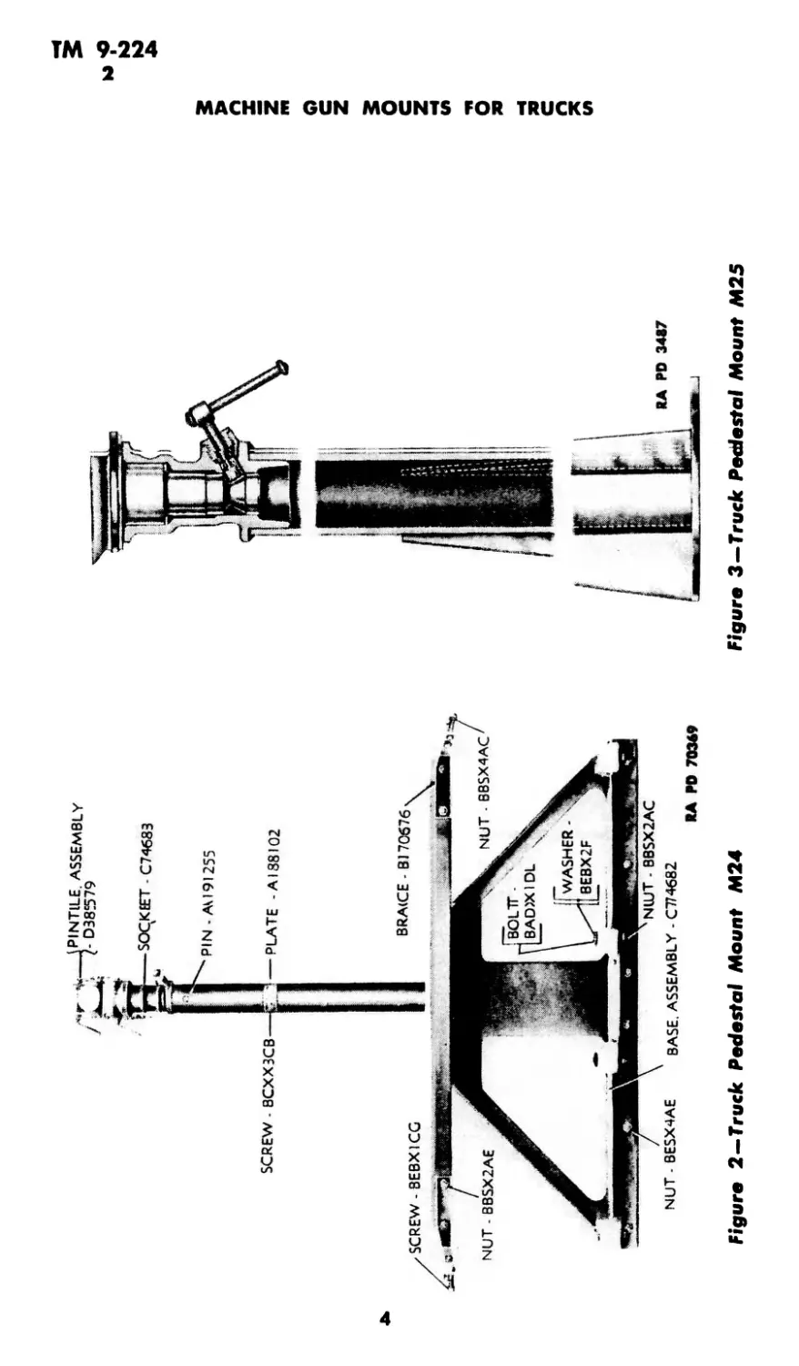
PINTILE. ASSEMBLY
- D38579
SCREW - 8CXX3CB
SOCKEET - C74683
PIN • AM 91255
PLATE -AI38I02
NUT - BESX4AE BASE. ASSEMBLY - C774682
RA ГО 703*9
Figure 2—Truck Pedestal Mount M24
3
ю
ю
Figure 3—Truck Pedestal Mount M25
ТМ 9-224
2
INTRODUCTION
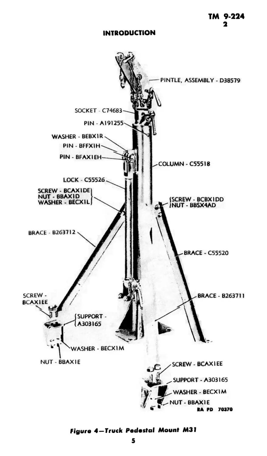
PINTLE, ASSEMBLY - D38579
SOCKET C74683
PIN - BFAX1EH
COLUMN - C55518
LOCK C55526
BRACE B2637I2
BRACE - C55520
(SCREW - BCBXIDD
I NUT - BBSX4AD
SCREW - BCAXIDE
NUT - BBAXID
WASHER - BECXIL
WASHER - BEBX1R
PIN - BFFX1H
WASHER - BECX1M
NUT -BBAX1E
SCREW - BCAXIEE
SUPPORT-A303165
WASHER - BECX1M
SUPPORT -
A303I65
NUT - BBAXIE
IA PD 70370
Figure 4—Truck Pedestal Mount M31
5
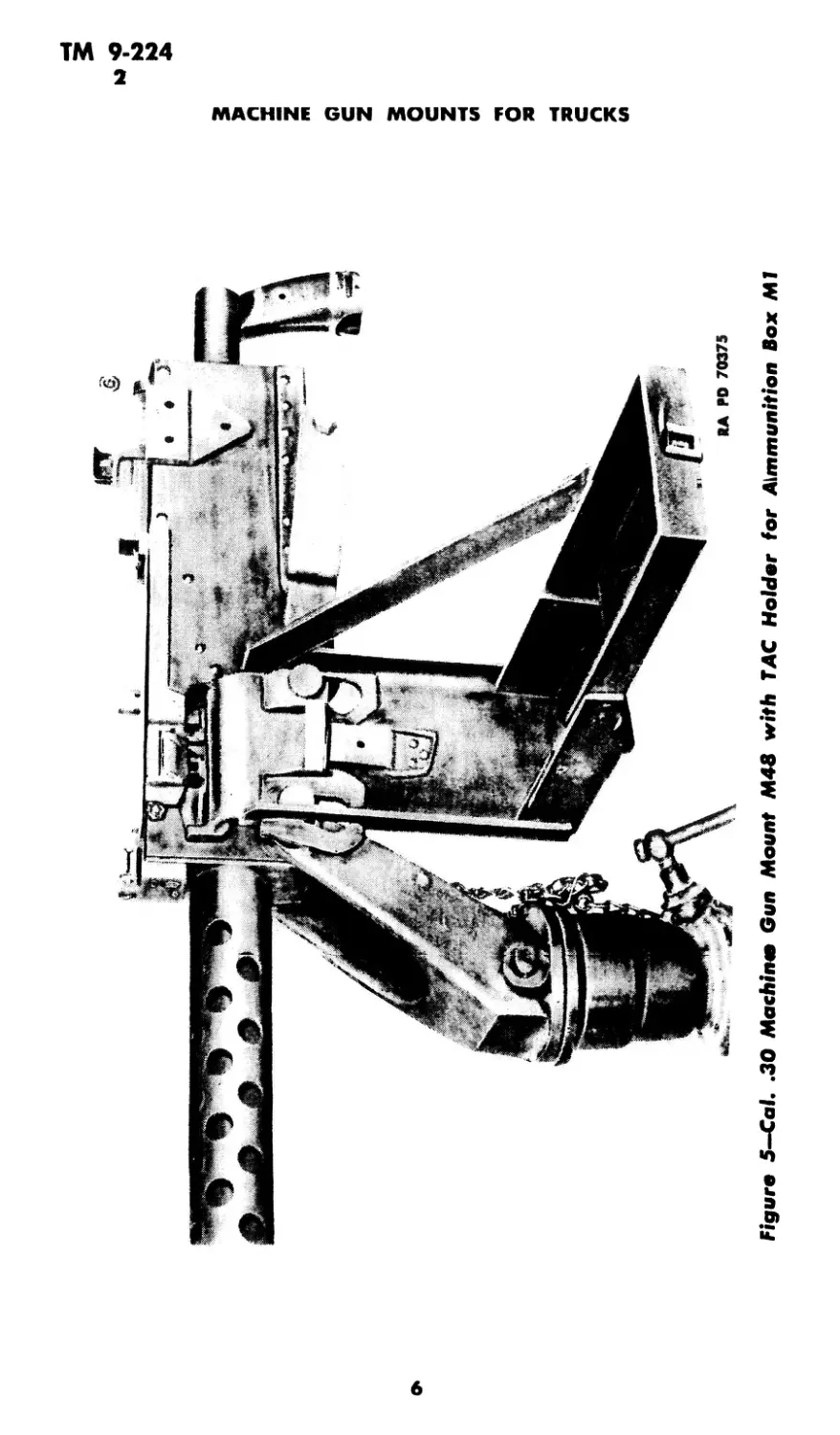
PIN - A191255
SCREW -
BCAXIEE
BRACE - B263711
Figure 5—Cal. .30 Machin* Gun Mount M48 with TAC Holder for Aimmunition Box Ml
w
MACHINE GUN MOUNTS FOR TRUCKS
CRADLE. ASSEMBLY - D40733
CARRIAGE, ASSEMBLY - D40721
SUPPORT - C90773
TRACK. ASSEMBLY - C90771
CLAMP. ASSEMBLY-Cl 06435
RA ГО 70371
ASSEMBLY - C90778
Figutre 6—Truck Mount M32—Luft Side View
ТМ 9-224
2
MACHINE GUN MOUNTS FOR TRUCKS
Figure 7—Truck Mount M36—Top View
b. Truck Mounts M32, M36, M37, М37Л1, and M37A2 (figs. 6,
7; and 8}. Each mount consists essentially of a cradle with а Г911?Г car-
riage on a circular track. The cradle is rotatable in the pintle sleeve of
the carriage, and is adjustable for elevation. The carriage is guided on
the track by means of rollers. The track is secured to the vehicle by
supports.
(1) Each mount can be used with either the Browning Machine Gun,
cal. .30, M1919A4, flexible, or Browning Machine Gun, cal. .50, М2,
heavy barrel, flexible.
(2) The trucks with which the mounts are used are as follows:
(a) The M32 Truck can be installed only on the 21/2-ton, 6x6, long
wheel base closed trucks with conventional steel bodies.
(b) The M36 Truck Mount is used on the following trucks:
1. 2*/a-ton, 6x6 (GMC), L.W.B., open cab truck.
2. 2*/2-ton, бхб (GMC), S.W.B., open cab truck.
3. 2l/2-ton, 6x6 (GMC), C.O.E., open cab truck.
8
ТМ 9-224
2
INTRODUCTION
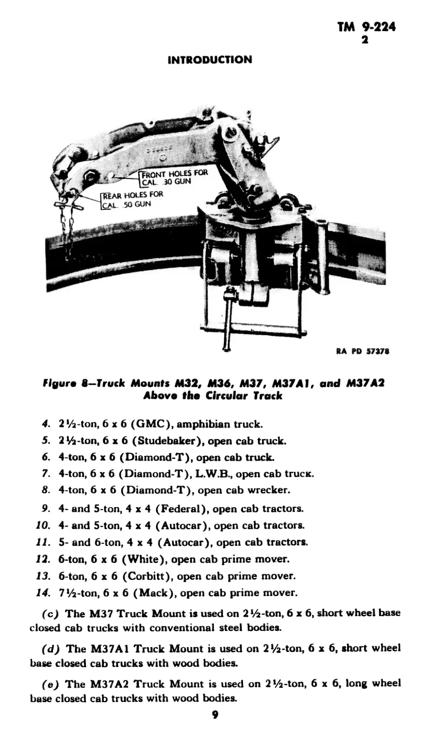
Figure 8—Truck Mounts M32, M36, M37, M37AI, and M37A2
Above the Circular Track
4. 2Vi-ton, 6x6 (GMC), amphibian truck.
5. 2 Vi-ton, 6x6 (Studebaker), open cab truck.
6. 4-ton, 6x6 (Diamond-T), open cab truck.
7. 4-ton, 6x6 (Diamond-T), L.W.B., open cab truex.
8. 4-ton, 6x6 (Diamond-T), open cab wrecker.
9. 4- and 5-ton, 4x4 (Federal), open cab tractors.
10. 4- and 5-ton, 4x4 (Autocar), open cab tractors.
11. 5- and 6-ton, 4x4 (Autocar), open cab tractors.
12. 6-ton, 6x6 (White), open cab prime mover.
13. 6-ton, 6x6 (Corbitt), open cab prime mover.
14. 7‘/a-ton, 6x6 (Mack), open cab prime mover.
(c) The M37 Truck Mount is used on 2 ‘Л-ton, 6x6, short wheel base
closed cab trucks with conventional steel bodies.
(d) The M37A1 Truck Mount is used on 2‘/2-ton, 6x6, short wheel
base closed cab trucks with wood bodies.
(e) The M37A2 Truck Mount is used on 2 ‘/2-ton, 6x6, long wheel
base closed cab trucks with wood bodies.
9
ТМ 9-224
3
MACHINE GUN MOUNTS FOR TRUCKS
RA RD 70371
Figure 9—Truck Pedestal Mount M24—Rear View with Pintle in
Auxiliary Socket
3. DIFFERENCES AMONG MODELS.
a. Truck Pedestal Mount M24 is similar to Truck Pedestal Mount
M24A1. However, the M24 Mount has an auxiliary socket to carry the
pintle in traveling position (fig. 9); whereas M24A1 Mount has none,
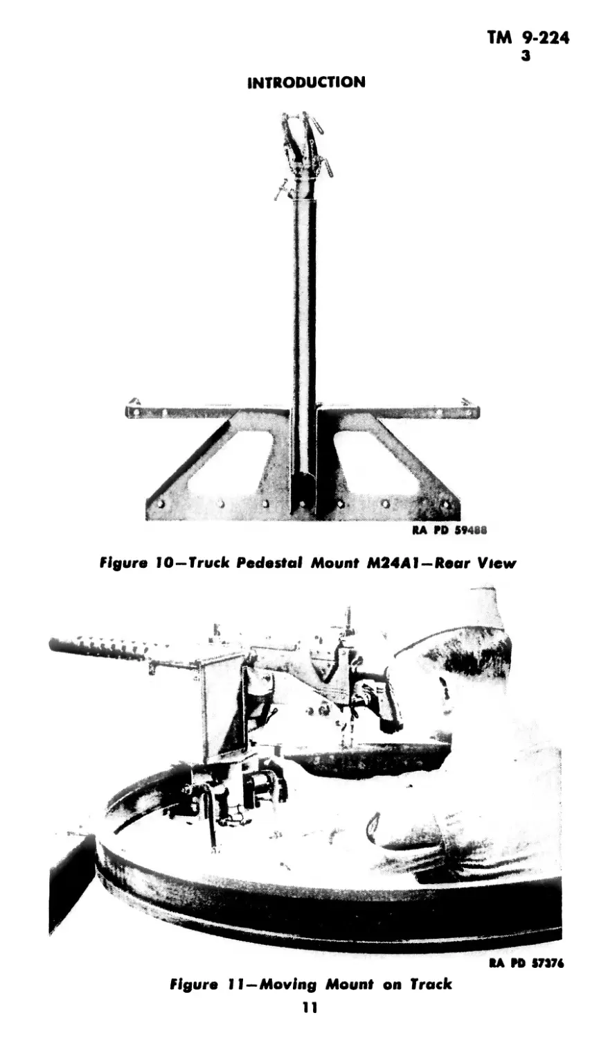
and the M24A1 Mount has the bottom of the tube cut off to facilitate
attachment to truck (fig. 10); whereas the M24 Mount does not have
the tube cut off at the bottom.
b. The portions of the Truck Mounts M32, М3 б, M37A1, and
M37A2 above, and including the circular rails, are identical, the only
differences being in the posts, braces, and other parts used to attach the
rail portion of the mount to the particular truck (fig. 8). These three are
ring type mounts; whereas the M24, M24A1, M25, and M48 are pedestal
type mounts.
10
ТМ 9-224
3
INTRODUCTION
Figure 10—Truck Pedestal Mount M24A1—Rear View
КД ГО 17374
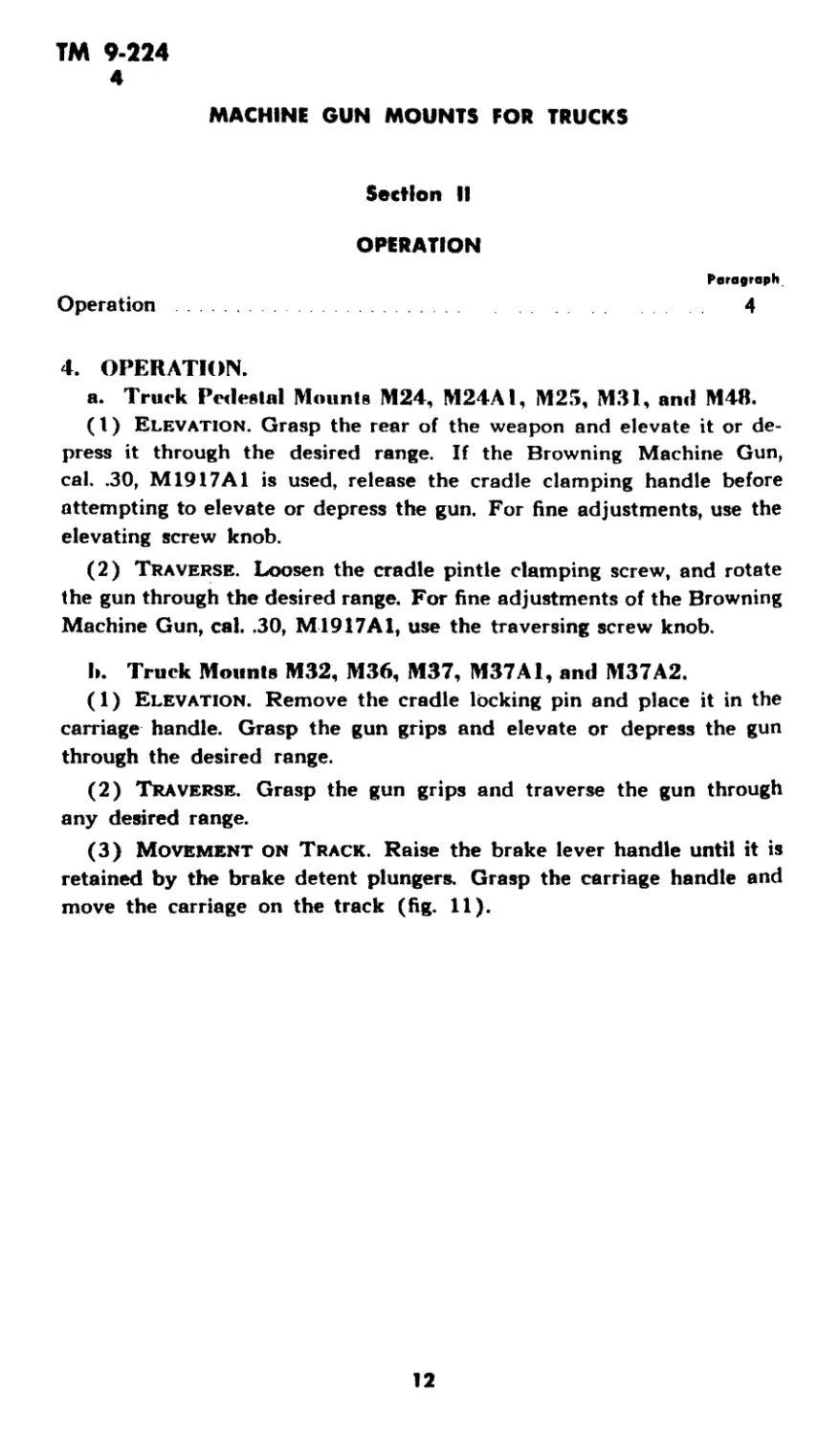
Figure 11—Moving Mount on Track
11
ТМ 9-224
4
MACHINE GUN MOUNTS FOR TRUCKS
Section II
OPERATION
Operation
Paragraph
4
4. OPERATION.
a. Truck Pedestal Mounts M24, M24A1, M25, M31, and M48.
(1) Elevation. Grasp the rear of the weapon and elevate it or de-
press it through the desired range. If the Browning Machine Gun,
cal. .30, M1917A1 is used, release the cradle clamping handle before
attempting to elevate or depress the gun. For fine adjustments, use the
elevating screw knob.
(2) Traverse. Loosen the cradle pintle clamping screw, and rotate
the gun through the desired range. For fine adjustments of the Browning
Machine Gun, cal. .30, M1917Al, use the traversing screw knob.
I». Truck Mounts M32, M36, M37, M37A1, and M37A2.
(1) Elevation. Remove the cradle locking pin and place it in the
carriage handle. Grasp the gun grips and elevate or depress the gun
through the desired range.
(2) Traverse. Grasp the gun grips and traverse the gun through
any desired range.
(3) Movement on Track. Raise the brake lever handle until it is
retained by the brake detent plungers. Grasp the carriage handle and
move the carriage on the track (fig. 11).
12
ТМ 9-224
5
Section III
MOUNTING AND DISMOUNTING WEAPONS
Paragraph
Mounting weapons on truck pedestal mounts M24, M24A1,
M25, and M48 5
Mounting weapons on truck pedestal mount М31............ 6
Mounting weapons on truck mounts M32, M36, M37, M37A1,
and M37A2............................................. 7
Dismounting weapons from mounts......................... 8
5. MOUNTING WEAPONS ON TRUCK PEDESTAL MOUNTS
M24, M24A1, M25, and M48.
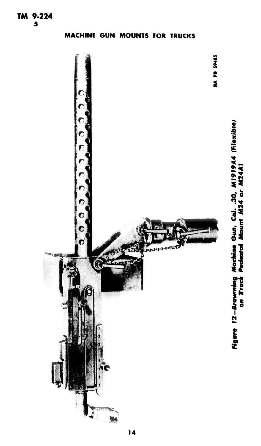
a. Browning Machine (am, Cal. .30, M1919A4, Flexible. Hold
the machine gun over the cradle pintle so that the front mounting holes
of the gun aline with the upper holes in the pintle. Secure the machine
gun to the pintle by inserting the thicker of the two locking pins
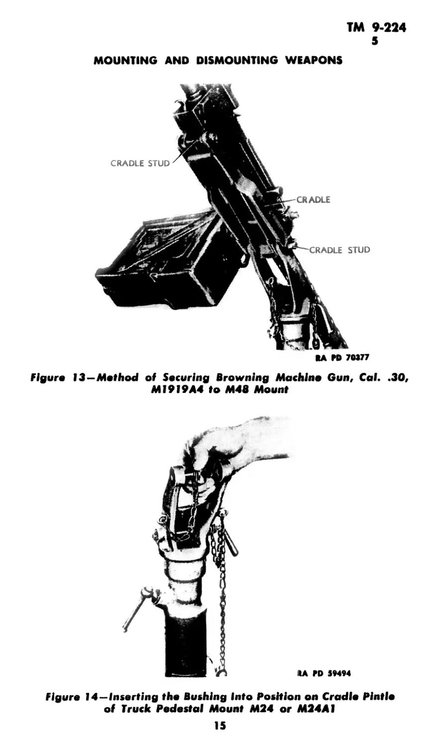
(fig. 12). In the case of the M48 Mount, the machine gun is secured at
the front and rear by means of the cradle and studs; the locking pins
are not used (fig. 13).
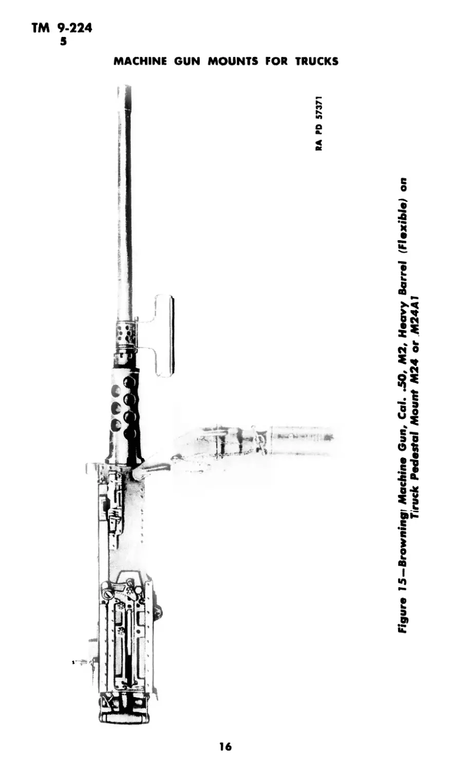
b. Browning Machine Gun, Cal. .50, М2, Heavy Barrel (Flex-
ible). Proceed as in paragraph 4 a (fig. 15).
c. Browning Automatic Rifle, Cal. .30, M1918A2.
(1) Insert the bushing into its place in the upper hole of the cradle
pintle (fig. 14).
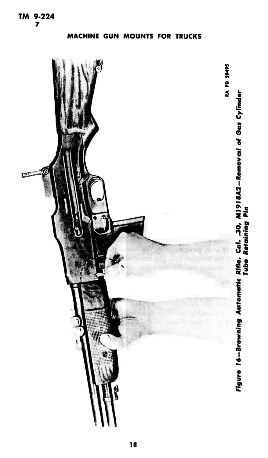
(2) With one hand, firmly grasp the barrel and forearm of the rifle;
and with the other hand, rotate the gas cylinder tube retaining pin
clockwise, and remove it (fig. 16). Do not release the hold on the rifle.
CAUTION: Take care not to lose the gas cylinder tube retaining pin.
(3) Hold the rifle over the cradle pintle so that the upper holes in
the pintle aline with the hole for the gas cylinder tube retaining pin.
Attach the rifle by inserting the thinner of the two locking pins (fig. 17).
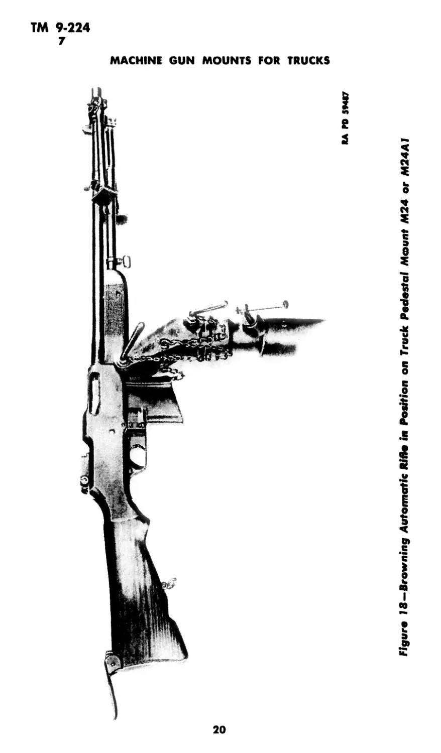
(4) The rifle is shown in position on the mount in figure 18.
13
Figure 12—Browning Machine Gun, Cal. .30, MI9J9A4 (Filexibiej
on Truck Pedestal Mount M24 or M24A1
ТМ 9-224
5
MOUNTING AND DISMOUNTING WEAPONS
КА ГО 70377
Figure 13—Method of Securing Browning Machine Gun, Cal. .30,
MI9I9A4 to M48 Mount
KA PD 59494
Figure 14—Inserting the Bushing Into Position on Cradle Pintle
of Truck Pedestal Mount M24 or M24AI
15
RA RD 57371
Figure 15—Browning) Machine Gun, Cal. .50, М2, Heavy Barrel (Flexible) on
Ttruck Pedestal Mount M24 or M24A1
ТМ 9>224
5-7
MOUNTING AND DISMOUNTING WEAPONS
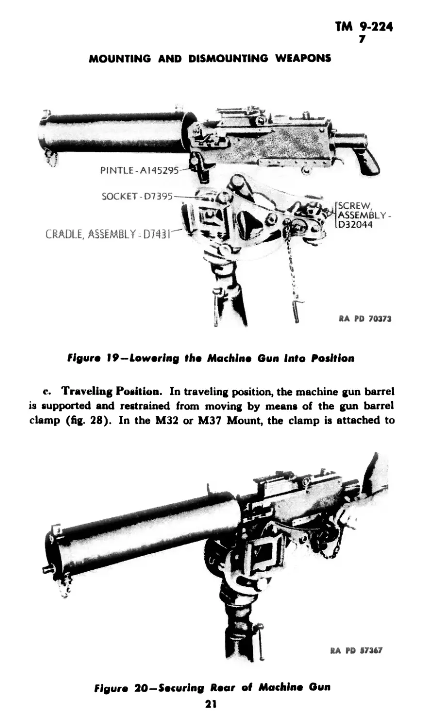
<1. Browning Machine Gun, Cal. .30, M19I7A1 with Cradle 1)7431
of Tripod Mount 1917A1.
(1) Loosen the cradle pintle clamping screw and remove the cradle
pintle from the pedestal socket (fig. 1). Insert Cradle D7431 of Tripod
Mount M1917A1 into the pedestal socket (fig. 19). Hold the machine
gun (with gun pintle attached) over the cradle, so that the gun pintle
alines with its socket in the cradle (fig. 19) and lower it into position.
(2 ) Lock the gun pintle by means of the gun pintle lock. Then adjust
the elevating knob until the rear mounting holes of the machine gun
aline with the hole in the elevating screw. Secure the rear of the
machine gun by inserting the elevating screw joint pin (fig. 20).
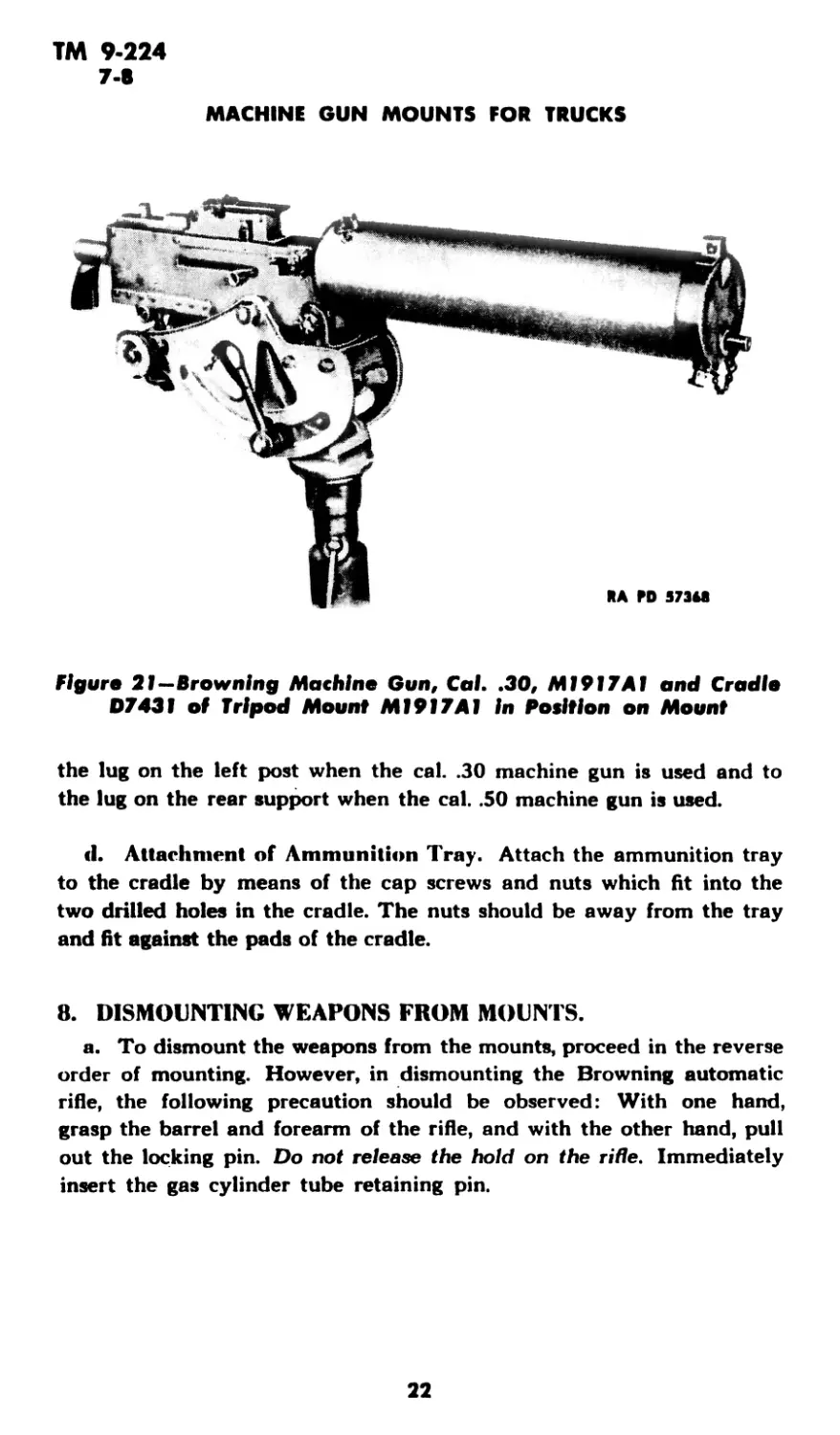
(3) The machine gun is shown in position on the mount in figure 21.
6. MOUNTING WEAPONS ON TRUCK PEDESTAL MOUNT M31.
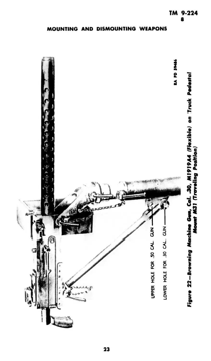
a. Browning Machine Gun, Cal. .30, M1919A4, Flexible. Proceed
as in paragraph 4 a. For traveling position, secure the traveling lock to
the machine gun. The lower end of the traveling lock is attached to the
pedestal through the lower hole on the bracket (fig. 22).
b. Browning Machine Gun, Cai. .50, М2, Heavy Barrel, Flexible.
Proceed as in paragraph 4 a. For traveling position, secure the traveling
lock to the machine gun. The lower end of the traveling lock is attached
to the pedestal through the upper hole on the bracket (fig. 23).
c. Browning Automatic Rifle, Cal. .30, M1918A2. Proceed as in
paragraph 5 c. The rifle is shown in position on the mount in figure 24.
d. Browning Machine Gun, Cal. .30, M1917A1 with Cradle
1)7431 of Tripod Mount MI917A1. Proceed as in paragraph 5 d.
7. MOUNTING WEAPONS ON TRUCK MOUNTS M32, M36, M37,
M37A1, and M37A2.
a. Browning Machine Gun, Cal. .30, M1919A4, Flexible.
(1) Turn up the pintle clamping screw, but do not tighten. Raise the
brake lever handle to lock carriage to the track. Adjust the cradle so
that the locking holes of the cradle pintle and cradle aline. Insert the
cradle locking pin and lock the cradle in the horizontal position (fig. 25).
17
ГЛ1 9-224
1В
ТМ 9-224
7
MOUNTING AND DISMOUNTING WEAPONS
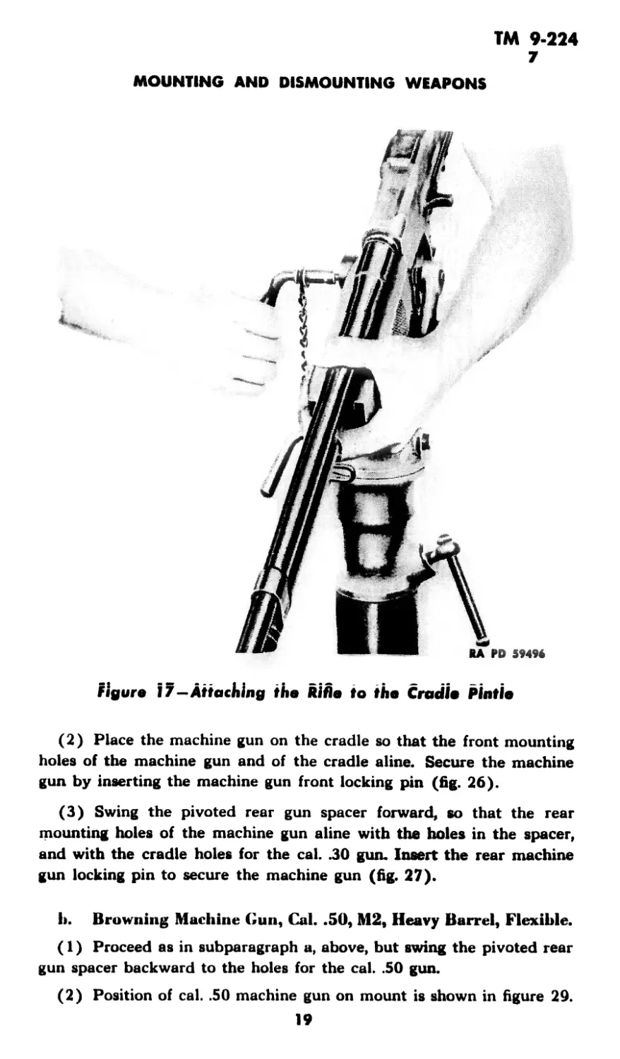
figure 17—Attaching the Rifle to the Cradle Pintle
(2) Place the machine gun on the cradle so that the front mounting
holes of the machine gun and of the cradle aline. Secure the machine
gun by inserting the machine gun front locking pin (fig. 26).
(3) Swing the pivoted rear gun spacer forward, so that the rear
mounting holes of the machine gun aline with the boles in the spacer,
and with the cradle holes for the cal. .30 gun. Insert the rear machine
gun locking pin to secure the machine gun (fig. 27).
h. Browning Machine Gun, Cal. .SO, М2, Heavy Barrel, Flexible.
(1) Proceed as in subparagraph a, above, but swing the pivoted rear
gun spacer backward to the holes for the cal. .50 gun.
(2) Position of cal. .50 machine gun on mount is shown in figure 29.
19
RA Ю S94S7
Figure J 8—Browning Automatic Rifle in Position on Truck Pedestal Mount M24 or M24A1
ТМ 9-224
7
MOUNTING AND DISMOUNTING WEAPONS
figure 19—Lowering the Machine Gun Into Position
c. Traveling Position. In traveling position, the machine gun barrel
is supported and restrained from moving by means of the gun barrel
clamp (fig. 28). In the M32 or M37 Mount, the clamp is attached to
figure 20—Securing Roar of Machine Gun
21
ТМ 9-224
7-8
MACHINE GUN MOUNTS FOR TRUCKS
Figure 21—Browning Machine Gun, Cal. .30, MI9I7AI and Cradle
D743I of Tripod Mount MI9I7AI In Position on Mount
the lug on the left post when the cal. .30 machine gun is used and to
the lug on the rear support when the cal. .50 machine gun is used.
<1. Attachment of Ammunition Tray. Attach the ammunition tray
to the cradle by means of the cap screws and nuts which fit into the
two drilled holes in the cradle. The nuts should be away from the tray
and fit against the pads of the cradle.
8. DISMOUNTING WEAPONS FROM MOUNTS.
a. To dismount the weapons from the mounts, proceed in the reverse
order of mounting. However, in dismounting the Browning automatic
rifle, the following precaution should be observed: With one hand,
grasp the barrel and forearm of the rifle, and with the other hand, pull
out the locking pin. Do not release the hold on the ride. Immediately
insert the gas cylinder tube retaining pin.
22
тот лм । (iravtiing гоигюп/
ТМ 9-224
8
MACHINE GUN MOUNTS FOR TRUCKS
figure 23—Browning Machine Gun, Cal. Л0, М2, Heavy Barral (flexible») on Truck
Pedestal Mount М31 (Traveling Position)
24
ТМ 9-224
8
MOUNTING AND DISMOUNTING WEAPONS
Figure 24—Browning Automatic BiBo, Cal. .30, MI918A2 on Track Potdestal Mount M31
25
ТМ 9-224
8
MACHINE GUN MOUNTS FOR TRUCKS
_A PD 5737J
figure 25—Truck Mounts M32, M36, M37, M37A1, and M37A2-
Locking the Cradle in the Horizontal Position
M PU 5/J/l
figure 26—Securing front of Cal. .30 Machine Gun to Truck Mounts
M32, M36, M37, M37AI, and M37A2
26
ТМ 9-224
8
MOUNTING AND
DISMOUNTING WEAPONS
RA M> 57374
Figure 27—Suturing Rear of Cal. .30 Machine Gun to Truck Mounts
МЗв, M37, M37AI, and M37A2
Figure 28—Mathine Gun Barrel Secured by Clamp
27
5
KA ГО 7KS74
BODY, ASSEMBLY -
LEVER -
SCREW, ASSEMBLY - A23O37 3^&-
-A230349
---LEVER -B195170
HANDLE -A23O483
CRADLE, ASSEMBLY-D4O733
MACHINE GUN MOUNTS FOR TRUCKS
Figure 29-Browning Machine Gun, Cal. JO, М2, Heavy Barrel ((Flexible) on Truck
Mounts M32, M36, M37, M37A1, or M37A2
ТМ 9-224
9-11
Section IV
DISASSEMBLY AND ASSEMBLY
Paragraph
General ................................................ 9
Disassembly and assembly of truck pedestal mounts...... 10
Disassembly and assembly of truck mounts .............. 11
9. GENERAL.
a. The following instructions for disassembly and assembly are de-
signed to enable the using arms to operate, clean, and inspect the
materiel.
b. Before proceeding with the disassembly of the mounts, remove
the weapons (par. 7).
10. DISASSEMBLY AND ASSEMBLY OF TRUCK PEDESTAL
MOUNTS.
a. Disassembly. Loosen the cradle pintle clamping screw and with-
draw the cradle pintle (and cradle, if attached).
b. Assembly. Make certain the bore of the pedestal socket is clear
(the clamping screw block is not in the way) and replace the cradle
pintle.
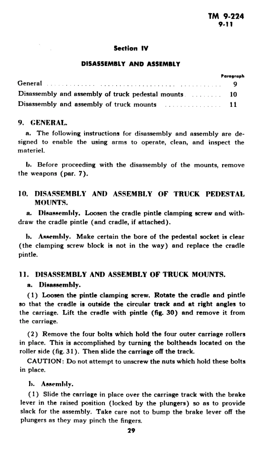
11. DISASSEMBLY AND ASSEMBLY OF TRUCK MOUNTS.
a. Disassembly.
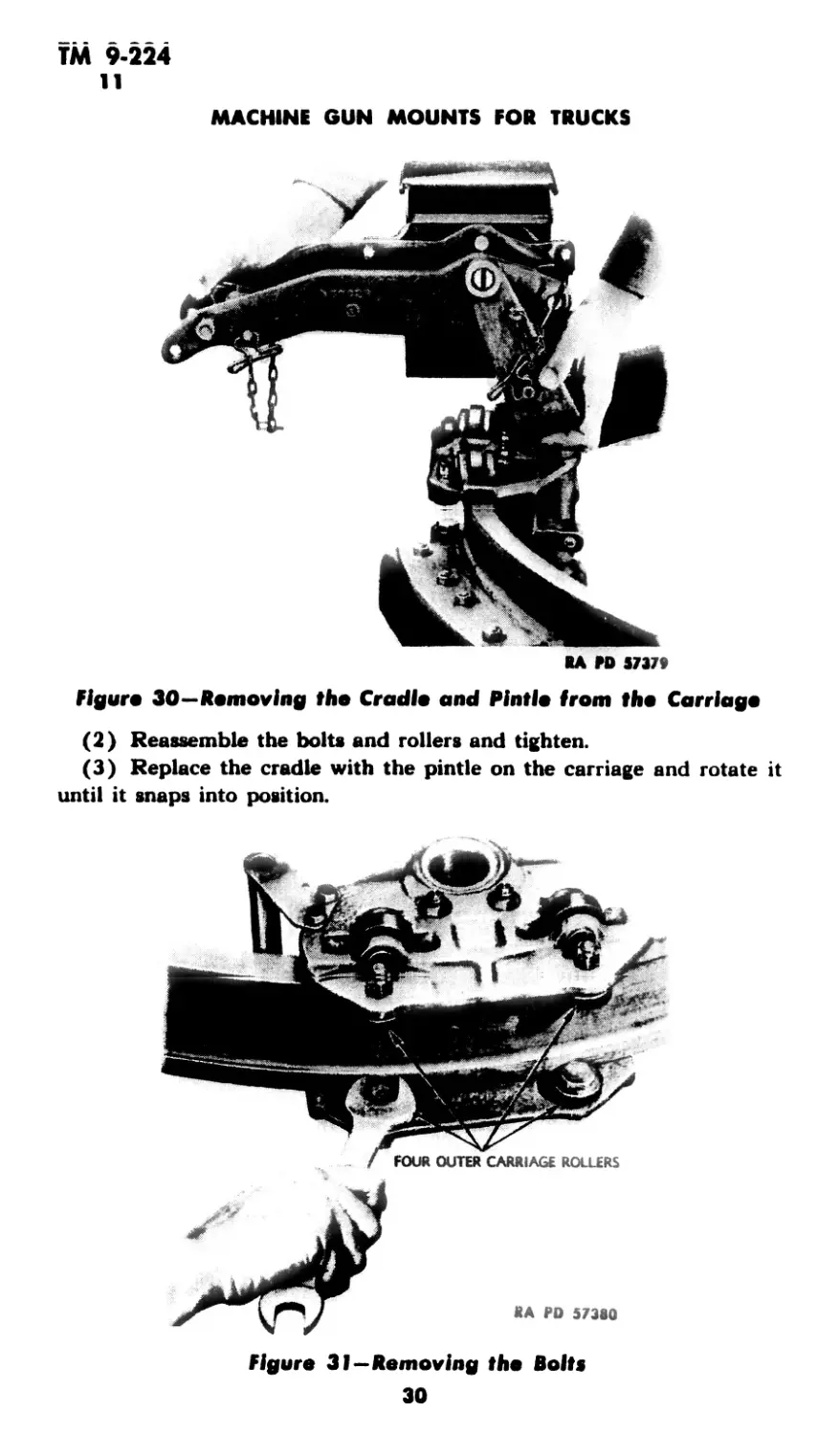
(1) Loosen the pintle clamping screw. Rotate the cradle and pintle
so that the cradle is outside the circular track and at right angles to
the carriage. Lift the cradle with pintle (fig. 30) and remove it from
the carriage.
(2) Remove the four bolts which hold the four outer carriage rollers
in place. This is accomplished by turning the boltheads located on the
roller side (fig. 31). Then slide the carriage off the track.
CAUTION: Do not attempt to unscrew the nuts which hold these bolts
in place.
I». Assembly.
(1) Slide the carriage in place over the carriage track with the brake
lever in the raised position (locked by the plungers) so as to provide
slack for the assembly. Take care not to bump the brake lever off the
plungers as they may pinch the fingers.
29
ТМ 9-224
11
MACHINE GUN MOUNTS FOR TRUCKS
KA FD S737»
flgun 30—Removing the Cradle and Pintle from the Carriage
(2) Reassemble the bolts and rollers and tighten.
(3) Replace the cradle with the pintle on the carriage and rotate it
until it snaps into position.
Figure 31—Removing the Bolts
30
ТМ 9-224
12-14
Section V
CARE AND PRESERVATION
Paragraph
General............................................................ 12
Cleaning of components received from storage....................... 13
Care in garrison and camp.......................................... 14
Care in the field and on the range .............................. 15
Care after firing.................................................. 16
Care in arctic climates ........................................... 17
Care in tropical climates.......................................... 18
Materiel affected by chemicals..................................... 19
12. GENERAL.
a. Proper functioning and accuracy of firing depend to a large extent
on care, cleaning, and oiling of the mount. All the operating parts of the
mount should be checked daily for cleanliness and lubrication in garri-
son and camp, in the field, and on the range. The following instructions
should be carefully observed.
13. CLEANING OF COMPONENTS RECEIVED FROM STORAGE.
a. Components which have been received from storage and are cov-
ered with COMPOUND, rust-preventive, should be cleaned with SOL-
VENT, dry-cleaning. Apply the solvent with rag swabs to large parts
and as a bath for small parts. Take care to remove all traces of the com-
pound, particularly from all recesses in which springs or plungers oper-
ate. After removing all traces of the compound, allow the parts to dry,
and then wipe with a clean, dry rag.
14. CARE IN GARRISON AND CAMP.
a. Care and cleaning in garrison and camp include care of the mount
necessary to preserve its condition and appearance during periods when
no firing is being done. Mounts should be inspected daily for proper
condition and cleanliness.
b. Remove the cradle pintle and with an oiled cloth wipe the con-
tacting surfaces of the pintle and the inside surface of the pintle socket.
Use OIL, lubricating, preservative, light.
c. Remove all dirt and rust from the track and wipe it with a cloth
oiled with OIL, lubricating, preservative, light Clean all unpainted metal
parts thoroughly and wipe with an oiled cloth. In case of rain, snow, or
dust storm, keep the machine gun on Truck Mounts M32, M36, and
М37 covered with the gun cover (fig. 32).
31
ТМ 9-524
15-17
MACHINE GUN MOUNTS FOR TRUCKS
Figure 32—Machine Gun Protected with Cover
15. CARE IN THE FIELD AND ON THE RANGE.
a. In general, it should not be necessary to disassemble the mount in
the field for cleaning. However, if the mechanism becomes very dirty and
operates sluggishly, remove the weapon and then remove and clean the
cradle pintle, gun pintle, and carriage. Then wipe with a cloth oiled with
OIL, lubricating, preservative, light, and assemble the mount.
16. CARE AFTER FIRING.
a. After firing, remove the weapon. Disassemble the mount and clean
the components with a dry, clean rag. Then wipe with a cloth oiled with
OIL, lubricating, preservative, light, and reassemble.
17. CARE IN ARCTIC CLIMATES.
a. In arctic climates it is essential that all moving parts be kept abso-
lutely free of moisture. Clean and lubricate all parts, but do not use ex-
cess lubricant because it may solidify to such an extent as to cause slug-
gish movement or even complete failure. When the materiel is in the
open, all unprotected parts should be covered with tarpaulin or other
suitable material. The covering selected should be firm, so that no loose
material will get into the working parts. When the materiel is transferred
32
ТМ 9-224
17-19
CARE AND PRESERVATION
from the outside into a heated building, it should be immediately cleaned
and oiled thoroughly to prevent the condensation of moisture. After the
materiel has reached room temperature, wipe it dry with a clean rag, and
oil again with OIL, lubricating, preservative, light.
18. CARE IN TROPICAL CLIMATES.
a. In hot and tropical climates where salt air is present, the materiel
should be inspected and cleaned frequently, when and as required, rather
than at fixed intervals. Clean and oil the materiel as soon as possible after
firing, when wet or dirty, or if there is any reason to expect corrosion to
start. In hot, but dry climates where sand or dust are prevalent, the un-
protected parts of the materiel should be covered with tarpaulin or other
suitable material. Oiling should be kept at a minimum because oil has a
tendency to collect dust which acts as an abrasive.
19. MATERIEL AFFECTED BY CHEMICALS.
a. For instructions on decontamination of materiel and treatment of
casualties, see FM 21-40 and TM 3-220.
33
TM 9=224
20-21
MACHINE GUN MOUNTS FOR TRUCKS
Section VI
INSPECTION
Paragraph
Purpose .................................................... 20
Procedure .................................................. 21
20. PURPOSE.
a. Inspection of your materiel is vital. Thorough systematic inspec-
tion at regular intervals is the best insurance against an unexpected
break-down at the critical moment when maximum performance is abso-
lutely necessary. Never let your materiel run down; keep it in first class
fighting condition by vigilant inspection and prompt maintenance.
b. Inspection is for the purpose of determining the condition of the
materiel and the repairs or adjustments necessary to insure serviceability
and proper functioning. Its immediate aim is preventive maintenance
which includes inspection for any damage caused by improper handling
before delivery into your hands and inspection for ordinary wear or de-
fects of parts that may require replacement.
21. PROCEDURE.
a. General. The instructions for inspection are given as a unit for
all the mounts listed in paragraph 1. Instructions which do not apply to
the particular mount in question should, therefore, be disregarded.
b. Mount as a Unit.
(1) Inspect the mount as a unit for condition, rigidity, or looseness of
component assemblies. Check for welding defects.
(2) Elevate and depress the weapon on the mount through the full
range and note any binding or sluggish movement.
(3) Rotate the mount through its full range and note any binding or
sluggish movement.
(4) Test the functioning of the cradle pintle clamping screw.
(5) Test functioning of gun pintle lock.
(6) Test functioning of cradle pintle clamping handle.
(7) Move the carriage on the track and note freedom of movement.
(8) Test functioning of brake lever assembly.
c. Cradle Group.
(1) Check for looseness of pintle support and pintle lock assembly.
Check for wear on plunger locking surface of gun pintle lock body.
(2) Check for wear on locking grooves of gun pintle.
(3) Test tension of gun pintle lock springs.
34
TM 9-224
21
INSPECTION
d. Socket Group.
(1) Test functioning of cradle pintle locking screw.
(2) Check whether the pintle socket block pin extends into the groove
on the underside of the block.
(3) Check whether the twist link machine chains are firmly riveted
to the pintle and properly secured to the locking pin bodies. Test func-
tioning of locking pin balls and springs.
e. Elevating and Traversing Mechanism.
(1) Operate the elevating and traversing knobs and note any binding,
sluggish movement, or lost motion. The clicks should be perceptible, and
each click should correspond to a change of one mil in elevation or
traverse.
(2) Note if elevating and traversing scales are loose. Markings on
scale should be clear and not chipped.
35
ТМ 9-224
22-23
MACHINE GUN MOUNTS FOR TRUCKS
Section VII
MAINTENANCE AND REFAIR
Paragraph
General.................................................... 22
Preventive maintenance .................................... 23
Replacement of worn of broken parts.................... 24
22. GENERAL.
a. The instructions for maintenance and repair are given as a unit for
all mounts listed in paragraph 1. Instructions which do not apply to the
particular mount in question should, therefore, be disregarded. The im-
mediate aim of these instructions is trouble prevention, which includes
preventive maintenance and replacement of worn or broken parts.
23. PREVENTIVE MAINTENANCE.
a. Tighten all bolts, nuts, and screws to prevent their becoming loose
in service. This should be done periodically when the vehicle is in use.
b. Remove all dirt and rust from the track and rollers.
c. Clean all oil fittings and passages, making certain that all dirt and
metal chips have been cleaned out. Clean the contacting surfaces on the
pintle and in the pintle socket.
<1 . The brake detent springs are properly adjusted before shipment.
If necessary, the brake detent plungers may be pulled in or out by grasp-
ing the screws directly behind the safety nuts on the plungers and turn-
ing the nuts (fig. 33).
e. As wear takes place on the spring-actuated brake lever assembly,
the handle will automatically move downward until the levers hit the
stops on the carriage. If this happens, adjust the brake levers as follows:
(1) Remove the two nuts on each end of the handle grip.
(2) Then remove the nuts and washers at the ends of the screws on
the upper portion of the levers. These levers fit the screw ends on 36
serrations.
(3) Mark the relative location of the lever and screw on each side as
assembled; then remove the levers and assemble them, one serration
higher on the screws, so as to raise the handle assembly.
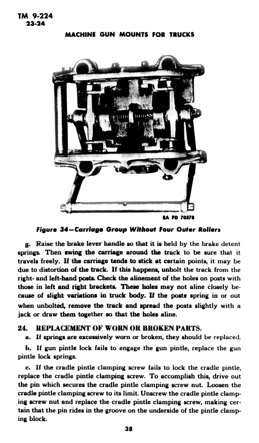
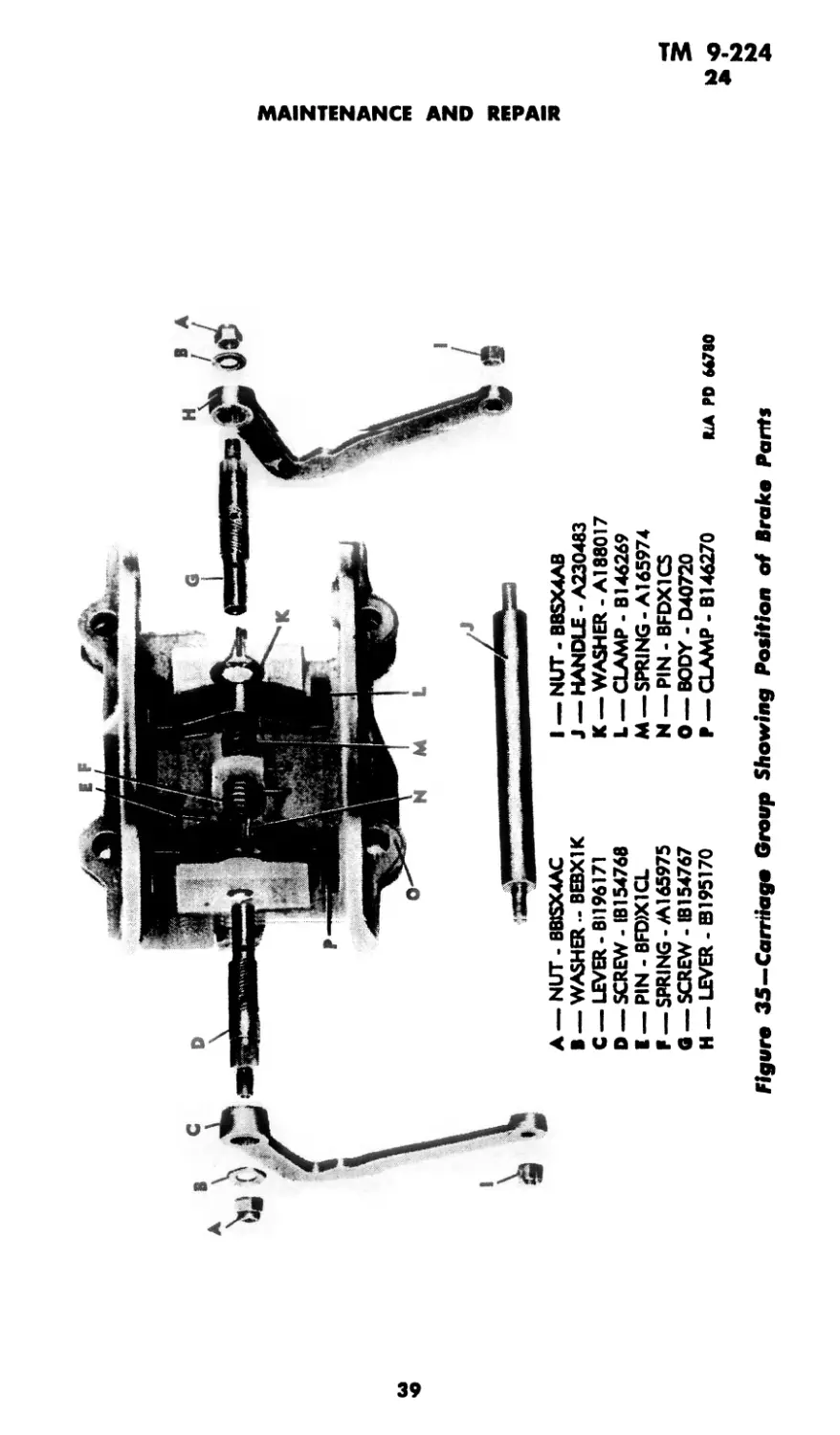
f. If there is not sufficient spring tension on the levers, remove the
carriage assembly from the track and wind the coil springs a quarter of
a turn. The screws on which these springs are anchored are cross-drilled
for this purpose (figs. 34, 35, and 36).
36
3& 1 2 ! *1
RA PO M782
Figure 33—Carriage Group Showing Brake Detent Springs and Plungers
A — PLUINGER - A230476
• — SPRUNG -A230394
C — NUT-BBSX4AA
0 —SCREW-BCBX1BA
К — PIN, ASSEMBLY - B195179
F — WASIHER - BEAX1K
Q _ HANDLE - A230349
H — BOD'Y - D40720
I — SCREW, ASSEMBLY - A230373
-ц
3
ТМ 9-224
23-24
MACHINE GUN MOUNTS FOR TRUCKS
RA M> 7037S
Figure 34—Carriage Group Without four Outer Rollers
g. Raise the brake lever handle so that it is held by the brake detent
springs. Then swing the carriage around the track to be sure that it
travels freely. If the carriage tends to stick at certain points, it may be
due to distortion of the track. If this happens, unbolt the track from the
right- and left-hand posts. Check the alinement of the holes on posts with
those in left and right brackets. These holes may not aline closely be-
cause of slight variations in truck body. If the posts spring in or out
when unbolted, remove the track and spread the posts slightly with a
jack or draw them together so that the holes aline.
24. REPLACEMENT OF WORN OR BROKEN PARTS.
a. If springs are excessively worn or broken, they should be replaced.
b. If gun pintle lock fails to engage the gun pintle, replace the gun
pintle lock springs.
c. If the cradle pintle clamping screw fails to lock the cradle pintle,
replace the cradle pintle clamping screw. To accomplish this, drive out
the pin which secures the cradle pintle clamping screw nut. Loosen the
cradle pintle clamping screw to its limit. Unscrew the cradle pintle clamp-
ing screw nut and replace the cradle pintle clamping screw, making cer-
tain that the pin rides in the groove on the underside of the pintle clamp-
ing block.
38
ы
ч>
А — NUT - BBSX4AC I — NUT - B8SX4AB
В —WASHER -ВЕВХ1К J — HANDLE - A230483
C —LEVER-Bl 196171
D —SCREW-IB154768
I — PIN - BFD)X1CL
F —SPRING-Al 65975
fl— SCREW - IB154767
H —LEVER - B195170
K —WASHER - Al 88017
L — CLAMP - В146269
M —SPRING-Al 65974
N — PIN - BFDX1CS
O —BODY - D40720
P — CLAMP B146270
ILA PD 66780
Figure 35—-Carrtfago Group Showing Position of Brake Pants
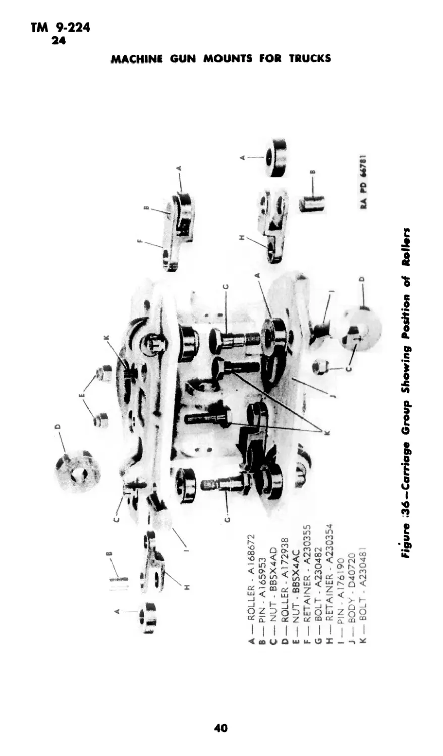
• ROLLER - A168672
PIN A165953
NUT - BBSX4AD
ROLLER - A172938
NUT - BBSX4AC
RETAINER - A230355
BOLT - A230482
RETAINER - A230354
PIN - A176190
BODY - D40720
BOLT - A23048I
Figure 136—Carriage Group Shewing Position of Rollers
О
C
z
KJ
KJ
TM 9-224
24
MAINTENANCE AND REPAIR
Figure 37—Socket Group
d. Replacing the cradle pintle clamping screw usually necessitates
replacing the pintle clamping block. Failure to lock the cradle pintle
indicates that the pintle clamping block has been sheared off the cradle
pintle clamping screw by forceful unscrewing of the latter from the
cradle pintle clamping screw nut. However, if the cradle pintle clamping
screw is bent or burred to an extent that it cannot be screwed all the way
into the cradle pintle clamping screw nut, preventing thg pintig с1йП1р=
ing block from firmly engaging the cradle pintle, replacement of the
cradle pintle clamping screw only is required (fig. 37).
e. If the small pin in the seat for the pintle clamping block does not
protrude the proper amount, locate its seat by scratching off paint about
3/4 inch below the center of the cradle pintle clamping screw nut. This
pin is Ух e inch in diameter. Drive it in with proper-sized steel punch, so
that it will keep the pintle clamping block properly positioned by means
of the groove on the underside of the pintle clamping block. If this pin
is missing, the pintle clamping block usually rotates with the cradle
pintle clamping screw; this does not allow the pintle clamping block fully
to engage the cradle pintle. This prevents locking the cradle pintle
(fig. 37).
41
ТМ 9-224
25-27
MACHINE GUN MOUNTS FOR TRUCKS
Section VIII
PAINTING
Paragraph
General.................................................... 25
Preparation of surfaces for painting....................... 26
Painting metal surfaces.................................... 27
Paint as camouflage........................................ 28
Removal of paint........................................... 29
25. GENERAL.
a. Ordnance materiel is painted before issue to the using arms and one
maintenance coat per year will ordinarily be ample for protection. With
but few exceptions, this materiel will be painted with ENAMEL,
synthetic, olive-drab, lusterless. The enamel may be applied over old
coats of long oil enamel and oil paint previously issued by the Ordnance
Department if the old coat is in satisfactory condition for repainting.
b. Paints and enamels are usually issued ready for use and are applied
by brush or spray. They may be brushed on satisfactorily when used
unthinned in the original package consistency, or when thinned no more
than five percent by volume with THINNER. The enamel will spray
satisfactorily when thinned with 15 percent by volume THINNER.
(Linseed oil must not be used as a thinner since it will impart a luster
not desired in this enamel.) If sprayed, it dries hard enough for repaint-
ing within У2 hour and dries hard in 16 hours.
c. Complete information on painting is contained in TM 9-850.
26. PREPARATION OF SURFACES FOR PAINTING.
a. If the base coat on the materiel is in poor condition, it is more de-
sirable to strip the old paint from the surface than to use sanding and
touch-up methods. After stripping, it will be necessary to apply a primer
coat.
b. PRIMER, synthetic, rust-inhibiting, for bare metal, should be used
on metal as a base coat.
c. The effectiveness of a painting job depends partly on the selection
of a suitable paint, but largely upon the care used in preparing the sur-
face prior to painting. All parts to be painted should be free of all extra-
neous matter such as rust, dirt, and grease, and must be dry.
27. PAINTING METAL SURFACES.
a. Metal parts in need of cleaning should be washed with a liquid
solution consisting of V2 pound of SODA ASH in 8 quarts of warm water,
42
ТМ 9-224
27-28
PAINTING
or an equivalent solution, then rinsed with clear water and wiped thor-
oughly dry. If the materiel is in fair condition and marred only in spots,
these places should be touched up with ENAMEL, synthetic, olive-drab,
lusterless, and permitted to dry. The whole surface should then be sand-
papered with PAPER, flint, class B, No. 1, and a finish coat of ENAMEL,
synthetic, olive-drab, lusterless, applied and allowed to dry thoroughly
before the materiel is used. If the equipment is in bad condition, all parts
should be thoroughly sanded with PAPER, flint, class B, No. 2, or equiva-
lent, given a coat of PRIMER, synthetic, refinishing, and permitted to
dry for at least 16 hours. They should then be sandpapered with PAPER,
flint, class B, No. 00, wiped free from dust and dirt, and given a final coat
of ENAMEL, synthetic, olive-drab, lusterless, and allowed to dry thor-
oughly before the materiel is used.
28. PAINT AS CAMOUFLAGE.
a. Camouflage is now a major consideration in painting ordnance
materiel with rust prevention secondary. The camouflage plan employed
at present utilizes three factors: color, gloss, and stenciling.
(1) Color. Vehicles are painted with ENAMEL, synthetic, olive-
drab, lusterless, which was chosen to blend reasonably well with the
average landscape.
(2) Gloss. The new lusterless enamel makes it difficult to see a
vehicle from the air or from relatively great distances over land. A
vehicle painted with ordinary glossy paint can be detected more easily
and at greater distances.
(3) Stenciling. White stencil numbers on materiel have been elim-
inated because they can be photographed from the air. A blue-drab stencil
enamel is now used which cannot be so photographed. It is illegible to
the eye at distances exceeding 75 feet.
b. Preservation of Camouflage.
(1) Continued friction or rubbing must be avoided, as it will smooth
the surface and produce a gloss. The materiel should not be washed more
than once a week. Care should be taken to see that the washing is done
entirely with a sponge or a soft rag. The surface should never be rubbed
or wiped, except while wet, or a gloss will develop.
(2) It is not desirable that materiel painted with lusterless enamel
be kept as clean as that covered with glossy paint. A small amount of dust
increases the camouflage value. Grease spots should be removed with
SOLVENT, dry-cleaning. Whatever portion of the spot that cannot be
so removed should be allowed to remain.
(3) Continued friction of wax-treated tarpaulins on the materiel will
also produce a gloss, which should be removed with SOLVENT, dry-
cleaning.
43
ТМ 9-224
28-29
MACHINE GUN MOUNTS FOR TRUCKS
(4) Tests indicate that repainting with olive-drab paint is necessary
once a year and with blue-drab paint twice a year.
29. REMOVAL OF PAINT.
a. After repeated paintings, the paint may crack and scale off in
places, presenting an unsightly appearance. If such is the case, remove
the old paint with a lime-and-lye solution (see TM 9-850 for details)
or with REMOVER, paint and varnish. It is important that every trace
of lye or other paint remover be completely rinsed off, and that the
equipment be perfectly dry before repainting is attempted. It is prefer-
able that the use of lye solutions be limited to iron or steel parts. If used
on wood, the lye solution must not be allowed to remain on the surface for
more than a minute before it is thoroughly rinsed off and the surface
wiped dry with rags. Crevices or cracks in wood should be filled with
putty and the wood sandpapered before refinishing. The surfaces thus
prepared should be painted according to directions in paragraph 26.
44
TM 9-224
30-31
Section IX
REFERENCES
Paragraph
Standard nomenclature lists................................ 30
Explanatory publications .................................. 31
30. STANDARD NOMENCLATURE LISTS.
a. Maintenance.
Cleaning, preserving and lubricating materials; recoil
fluids, special oils, and miscellaneous related items. SNL K-l
Soldering, brazing and welding material, gases and re-
lated items .................................... SNL K-2
Truck, small arms repair, Ml.................... SNL G-72
b. Mount Materiel.
Mounts, small-arms, for motor vehicles.......... SNL A-55
Current Standard Nomenclature Lists are as tabulated
here. An up-to-date list of SNL’s is maintained as the
“Ordnance Publications for Supply Index”........... OPSI
31. EXPLANATORY PUBLICATIONS,
a. Maintenance.
Chemical decontamination materials and equipment. . TM 3-220
Cleaning, preserving, lubricating, and welding ma-
terials and similar items issued by the Ordnance
Department ..................................... TM 9-850
Defense against chemical attack................. FM 21-40
Field inspection of ordnance materiel by service com-
mand inspectors in continental United States.... ТВ 1100-1
Military chemistry and chemical agents.......... TM 3-215
45
ТМ 9-224
MACHINE GUN MOUNTS FOR TRUCKS
INDEX
Д Pags No.
Adjustment, spring-actuated brake
lever assembly .................... 36
Alinement of holes in brake lever
handle............................ 38
Ammunition tray, attachment of 22
Arctic climates, care of weapon in 33
Assembly:
truck mounts.................... 29 30
truck pedestal mounts........... 29
Automatic rifle, Browning, cal. .30,
M1918A2, mounting on truck
pedestal mount ................... 13
В
Brake detent springs, maintenance
and repair ........................ 36
Brake levers, maintenance, adjust-
ment, and repair................... 36
Browning automatic rifle (See Auto-
matic rifle, Browning, cal. .30,
M1918A2)
Browning machine guns (See specific
names under machine guns)
c
Cal. .30 machine gun mount M48
Page No.
Cautions:
disassembly of truck mounts 29
mounting Browning automatic
rifle, cal. .30, on truck pedes-
tal mount....................13
Characteristics:
carriage........................... 8
cradle............................. 8
truck mounts............. 8 9
truck pedestal mounts........... 2 3
Cleaning:
components received from storage 31
oil fittings ..................... 36
Cradle
description and characteristics 8
replacement
pintle clamping block 41
pintle clamping screw 38 41
Cradle group, inspection 34
Cradle pintle (clamping screw)
care and preservation 31
replacement 38 41
(See Truck pedestal mounts)
Camouflage
paint as............................. 43
preservation 43-44
Camp and garrison, care of weapon
in 31
Care and preservation
after firing ...................... 32
arctic climates ................... 33
camouflage ..................... 43-44
cleaning of components received
from storage.................. 31
cradle pintle................. ... 31
decontamination.....................33
field and range.................... 32
garrison and camp 31
track .31
tropical climates 33
Carriage
description and characteristics 8
inspection........................ 34
movement on track.................. 12
sticking, cause and remedy ........ 38
D
Decontamination of materiel ex-
posed to gas 33
Description:
carriage 8
cradle 8
truck mounts 8 9
truck pedestal mounts 2 3
Differences among models of mounts 10
Disassembly:
truck mounts 29 30
truck pedestal mounts 29
t
Elevating and traversing mechanism,
inspection 35
Elevation of truck mounts and truck
pedestal mounts. ... 12
G
Gun pintle lock (See Pintle lock
(assembly) )
I
Inspection:
cradle group ....................... 34
elevating and traversing mechan-
ism ............................35
mounts 34
socket group 35
46
ТМ 9-224
INDEX
L Page No.
Lubricating oil 31, 32, 33
M
Machine gun, Browning, cal. .30,
M1917A1 with cradle D7431 of
tripod mount M1917A1, mounting
on truck pedestal mount 17
Machine gun, Browning, cal. .30,
M1919A4, flexible
mounting on truck mounts 17
mounting on truck pedestal
mounts 13
Machine gun, Browning, cal. .50, М2,
heavy barrel, flexible
mounting on truck mounts 17-19
mounting on truck pedestal
mounts .17
Maintenance and repair
preventive maintenance 36-38
replacement of worn or broken
parts 38-41
Metal parts, unpainted» care and
preservation . 31
Metal surfaces, painting 42-43
Models of mounts, differences among 10
Mounts (See Truck mounts and
Truck pedestal mounts)
Movement of truck mounts on track 12
Роде No.
Preservation (See Care and preser-
vation )
Preventative maintenance (See
Maintenance and repair)
R
Repair (See Maintenance and re-
pair)
Replacement of worn or broken parts
cradle pintle clamping screw . . 38-41
gun pintle lock................... 38
pin tn pintle clamping block 41
Rifle, automatic, Browning (See
Automatic rifle, Browning, cal. .30,
M1918A2)
s
Socket group, inspection........... 35
Spring-actuated . brake lever as-
sembly, maintenance and repair. . 36
Spring tension, maintenance...... 36
Springs, brake detent, maintenance
and repair........................ 36
Sticking of carriage, cause and
remedy............................ 38
Storage, cleaning components re-
ceived from....................... 31
Surfaces, preparation for painting 42
О
Oil, lubricating 31, 32, 33
Oil fittings, cleaning 36
Operation
truck mounts ... 12
truck pedestal mounts . 12
P
Paint(-ing)
as camouflage . 43-44
metal surfaces 42-43
preparation for 42
removal 44
Pin, pintle clamping block, replace-
ment 41
Pintle, description and character-
istics . 2
Pintle clamping block (pin), re-
placement 41
Pintle clamping screw (cradle), re-
placement 38-41
Pintle lock (assembly)
inspection ........................ 34
replacement ....................... 38
Pintle support, inspection .......... 34
T
Track
care and preservation . 31
movement of truck mounts on 12
securing to the vehicle 8
Traveling position of machine gun
barrel on truck mounts 21-22
Traverse of truck and truck pedes-
tal mounts ....................... 12
Traversing and elevating mecha-
nism, inspection of............... 35
Tray, ammunition, attachment of 22
Tripod mount 1917 Al, mounting
machine gun, cal. .30, M1917A1
with cradle .17
Tropical climates, care of weapon
in 33
Truck mounts
assembly 29 30
care and preservation 31-33
description and characteristics 8-9
differences among models............... 10
disassembly......................29-30
cautions ....................... 29
Д7
TM 9-224
MACHINE GUN MOUNTS FOR TRUCKS
T—Cont'd ₽a9« No.
Truck mounts—Cont’d
dismounting ....................... 22
inspection ................... 34-35
maintenance and repair....... 36-41
mounting weapons
attachment of ammunition tray 22
machine gun, Browning, cat .30,
M1919A4, flexible 17
machine gun, Browning, cal. .50,
М2, heavy barrel, flexible 17-19
movement on track................ 12
operation ....................... 12
traveling position .......... 21-22
traverse ........................ 12
use of ..........................8-9
Truck pedestal mounts
adjustment ........................ 12
assembly and disassembly ........ 29
care and preservation.........31-33
description and characteristics . 2-3
differences among models ........ 10
dismounting . . ................. 22
inspection ................... 34-35
maintenance and repair ...... 36-41
Fags No.
mounting weapons
automatic rifle, Browning, cal.
.30, M1918A2 13, 17
machine gun, Browning, cal. .30,
M1917A1 with cradle D7431
of tripod mount 1917A1 17
machine gun, Browning, cal. .30,
M1919A4, flexible 13, 17 19
machine gun, Browning, cal. .50,
М2, heavy barrel, flexible 13
operation ..................... 12
traverse ...................... 12
weapons used................... 2 3
Trucks, mounts used with 2 3, 8 9
w
Weapons
dismounting from mounts 22
inspection..................... 34
mounting on truck mounts 17-22
mounting on truck pedestal
mounts 17
used with truck pedestal mounts 2 3
Copyright 2008 Mil-Media Baxley
GA
A.G. 062.11 (3-26-43)
O.O. 461/36580 O.O. (4-20-43)
By order of the Secretary of War:
G. C. MARSHALL,
Chief of Staff.
Official:
J. A. ULIO,
Major General,
The Adjutant General.
Distribution: R 9(4); Bn & H(2); C 9(8), 5, 6, 17, 18 & 44(5);
1C 2 & 7(5)
(For explanation of symbols, see FM 2L6)
48
PUBLICATIONS DEPARTMENT, RARITAN ARSENAL.