/


Теги: mechanics repair manual repair


Текст
Service News AT20461 Page 1 of 4
Subject:
1. Introduction
The No. 1 pump metal tube may crack and oil may leak.
If this failure occurs, modify it according to this Service News.
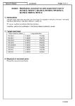
2. Target machine serial Nos.
3. Improvement details
Replace the metal tube and eyebolts with the improved ones.
No.1油圧ピストンポンプ
708-25-19140 706-46-53180
708-2L-29540 708-2L-29560
Modification procedure for cracks in No. 1 pump metal tube in
PC750-6/-7, PC800-6/-7, PC1250-7/-8/-11
Current
New
Tube Eyebolt
No. 1 Pump
No. 3 Pump
No. 2 Pump
Control Pump
TUBE
EYE BOLT
D=Φ8mm
D=Φ10mm
T=14mm
T=16mm
L=30mm
L=32mm
From To From To
1 PC750-6 708-2L-00751 708-2L-00752 DZ5 0001 DZ5 50282 10001 11081
2 PC750-7 708-2L-00762 708-2L-00763 DZX 0001 DZX 51486 20001 20404
3 PC800-6 708-2L-00751 708-2L-00752 DZ5 0001 DZ5 50282 30001 31111
4 PC800-7 708-2L-00762 708-2L-00763 DZX 0001 DZX 51486 40001 40644
5 PC1250-7 708-2L-00612 708-2L-00613 DZT 0001 DZT 51516 20001 20849
6 PC1250-8 708-2L-00681 708-2L-00682 DNF 0001 DNF 52612 30001 30677
7 PC1250-8R 708-2L-00681 708-2L-00682 DNF 0001 DNF 52612 35001 36133
8 PC1250-11 708-2L-02110 708-2L-02111 DGX 0001 DGX 50089 50001 50082
Previous Target serial Nos.
pump S/N
Target machine Target pump serial Nos.
models
Countermeasure
pump S/N
#
T D
L
AT20461
Service News AT20461 Page 2 of 4
4. Modification procedure
4-1. Modification parts list
(1) Tube: 1 pc. (2) Eyebolt: 2 pcs.
(3) O-ring: 4 pcs.
4-2. General precautions
When performing this modification, confirm the following descriptions and secure the safety.
1)
2)
3) Be very careful not to damage small parts while carrying, assembling, or disassembling them.
4) Check that the parts are correct in quantity and free from damage before starting work.
5)
6)
7) When assembling the parts, prevent entry of dirt and other foreign material into the piping.
8)
Prepare an indoor work space (or outdoor work space on sunny days) where wind, rain, or dust
does not affect the work and you can work easily.
Pay much attention to safety during work. Particularly, secure a level surface of sufficient size for
the work.
For disassembly, assembly, or handling procedures not shown in this Service News, see Shop
Manual or "Operation and Maintenance Manual".
If any part gets in the way of work and no instruction is given for it in this Service News, remove
it, and install it again after finishing the work.
Tighten the bolts according to Shop Manual, "Table of standard tightening torque", unless
otherwise specified.
No. Part name Part No. Q'ty Use
(1) Tube 708-2L-29540 1 Improved part
(2) Eyebolt 708-2L-29560 2 Improved part
(3) O-ring 07000-B2012 4 Consumable part
AT20461
Service News AT20461 Page 3 of 4
(I) For PC750-6/-7 or PC800-6/-7
4-3. Remove cracked tube
View Z
No. 1 Pump
View z
Eyebolts <2> Tube <1>
Actual tube location
4-4. Install new tube
1)
2)
3)
Eyebolt <2>, Width across flats: 22
Tightening torque: 15.7 to 19.6 Nm (1.6 to 2.0 kgm)
O-rings <3> Apply oil to seats and tighten to torque specified above.
Current New
ID mark
Top view Top view
4-5. Check after modification
1)
2) Start the engine, and check for oil leakage from each section.
Install O-rings <3> to the upper and lower joints of the tube 2 pieces each (4 pieces in total), while
taking care not to drop or catch them.
Check that the identification mark is on each replacement eyebolt (center mark of φ3 on the
eyebolt top).
Evenly apply hydraulic oil 1 or 2 drops each to the seats of eyebolts <2>, and gradually tighten
eyebolts <2> alternately.
Bleed air from hydraulic pump
Bleed air from each section. For details, see Shop Manual, “Testing and adjusting”, "Bleed air from
each secion".
Loosen eyebolts <2> at 2 places, and remove tube <1>.
Discard the cracked tube.
AT20461
Service News AT20461 Page 4 of 4
(II) For PC1250-7/-8/-11
4-3. Remove cracked tube
View Z
Eyebolts <2> Tube <1> View Z No. 1 Pump
Actual tube location
4-4. Install new tube
1)
2)
3)
Eyebolt <2>, Width across flats: 22
Tightening torque: 15.7 to 19.6 Nm (1.6 to 2.0 kgm)
O-rings <3> Apply oil to seats and tighten to torque specified above.
Current New
ID mark
Top view Top view
4-5. Check after modification
1)
2) Start the engine, and check for oil leakage from each section.
Install O-rings <3> to the upper and lower joints of the tube 2 pieces each (4 pieces in total), while
taking care not to drop or catch them.
Check that the identification mark is on each replacement eyebolt (center mark of φ3 on the
eyebolt top).
Evenly apply hydraulic oil 1 or 2 drops each to the seats of eyebolts <2>, and gradually tighten
eyebolts <2> alternately.
Bleed air from hydraulic pump
Bleed air from each section. For details, see Shop Manual, “Testing and adjusting”, "Bleed air from
each secion".
Loosen eyebolts <2> at 2 places, and remove tube <1>.
Discard the cracked tube.
AT20461