/


Теги: weapons military affairs machine gun
Год: 1940

Текст
ТМ 9-226
WAR DEPARTMENT
TECHNICAL MANUAL
BROWNING MACHINE GUN,
CALIBER .50, М2, WATER-COOLED,
AND MOUNTS
TM 9-226
*С 1
Changes 1 Off АВ DEPARTMENT,
No. 1 J ^^▲shingtoh, May 16, 1942.
TECHNICAL MANUAL
BROWNING MACHINE GUN, CALIBER .60, М2, WATER-COOLED,
AND MOUNTS
TM 9-226, December 10, 1940, is changed as follows:
25. Care and cleaning of gun.—a. Cleaning bore.—(1) Disas-
semble groups from gun. The bore should be cleaned thoroughly
with rifle bore cleaner. This cleaner is a combination solvent
and preservative which is issued for use by troops in the field
for cleaning small arms. For specifications of cleaners, oils,
and rust-preventive compounds, see TM 9—850 and SNL К—1.
(a) To use rifle bore cleaner, saturate a clean patch with
rifle bore cleaner and push it back and forth through the bore
of the barrel by means of a cleaning rod. Repeat the opera-
tion with dean patches two or three times, and then use a
clean dry patch to remove all the cleaner before applying the
prescribed lubricating oil, preservative, light.
(6) Lubricating oil, preservative, light (if unavailable,
lubricating oil for aircraft instruments and machine guns),
should be used to protect the bore if the weapon is to remain
out of service for several days. For long-time storage, rust-
preventive compound, light, should be used in place of oil.
See d below. However, before use, the gun should be deaned
thoroughly and reoiled with lubricating oil, preservative,
light.
(2) When rifle bore deaner is not available, proceed as
follows: Place barrel, muzzle down, in a vessel containing hot water
and issue soap or a soda ash and water solution (1% tablespoons
per pint of water), or, lacking these, hot or cold water alone.
*******
o. Cleaning tripod.
*******
(2) For the antiaircraft machine-gun mount, caliber Л0, М2, use
lubricating oil, preservative, light. If not available, use
lubricating oil for aircraft instruments and machine guns.
Lubricate the slide of the recoil mechanism through the oil hole
located in the top of the slide. The slide should be lubricated every
•Tbwe change* rapened* «ection Ш, Training Circular No. 71» War Department, 1*41.
' M558143
ТМ 9-226
О 1 TECHNICAL MANUAL
2 hours during continuous firing. The elevating and traversing screw
should be oiled with a few drops of oil every day.
Preparation far storage,
♦ * ♦ ♦ ♦ ♦ *
(2) Apply rust-preventive compound, light, to all metal parts
of the gun. Rust-preventive compound, light, is to he used on
guns for both temporary and permanent storage. It may be
applied with a brush or by dipping. In applying, heating is not
necessary except in very cold temperatures. Application of the rust-
preventive compound • • • whenever the weapon is not in use.
g, Lubricating oil,—(1) (a) Proper oiling is second in importance
only to intelligent cleaning. It is a vital necessity ♦ * * and the
ways of the belt feed slide.
(d) Lubricating oil, preservative, light, has preservative
as well as lubricating properties, and care should he taken to
use it where permissible. If lubricating oil, preservative,
light, is not available, lubricating oil for aircraft instruments
and machine guns may be used. However, the latter oil must
not be considered as a preservative. In a warm, humid at-
mosphere, metal surfaces covered with lubricating oil for air-
craft instruments and machine guns will not be suitably
protected against rusting. Lubricating oil, preservative,
light, should always be used for preserving the bore between
firings, after the barrel has been cleaned.
Note.—All guns which axe not protected with ruet-preventive compound
must be inspected periodically for signs of rust, the interval between in-
spections depending upon local climatic conditions.
(2) If the gun is to be fired in areas where the temperature is 45°
F. or above, oil, sperm, should be used when available. When not
available, engine oil, SAE 10, or any light grade machine oil may
be used in an emergency.
(3) On all types of machine guns, when operated in areas where
the temperature is below 45° F., oil, lubricating, for aircraft in-
struments and machine guns, should be used.
(4) For lubricating the М2 mount, sperm oil (U. S. Army Spec.
No. 2-45A) or aircraft instrument and machine-gun lubricating oil
should be used under the same conditions as in the case of the gun.
If either of these is not available, any suitable motor oil or machine
oil may be used.
[A. G. 062.11 (11-26-41) (8-20—42).] (C1. May 16,1942.)
2
ТМ 9-226
BROWNING MACHINE GUN, CALIBER .50, М2 Cl
26. Method of filling oil buffer.—Remove the oil buffer tube
filling screws from the base of the buffer tube. Use the oil buffer
filling oiler filled with aircraft instrument and machine-gun
lubricating oil. Start the flow of oil by pressing on the base of
the oiler. While the oil continues to pour * * * when the buffer
tube is completely full.
(A. G. 062.12 (11-26-41).] (C 1. May 16.1942.)
By order of the Secretary of War :
Official:
J. А. ЦЫ0,
Major General)
The Adjutant General.
G. C. MARSHALL,
Chief of Staff.
a. ». 4OVKRRRENT PRIRTIR4 OFFICE 11041
8
ТМ 9-226
О 9
TECHNICAL MANUAL
BROWNING MACHINE GUN, CALIBER Л0, М2,
WATER-COOLED, AND MOUNTS
Charges 1 WAR DEPARTMENT,
No. 2 j Washington, July 30, 1942.
TM 9-226, December 10,1940, is changed as follows:
7. Description of antiaircraft machine-gun mount, caliber
.50, М2.
♦ ♦♦♦♦♦♦
h. (5) Adjustment of recoil mechanism (fig. 7).—(a) With the
upper buffer recoil spring at its assembled length (2.09 inches)
screw in the counter-recoil spring adjusting plug until its
front face is 7%2 inches from the front faces of the trunnion
slide assemblies. It will be found convenient to block the
trunnion slide assembly to this height before assembling
spring and plug to assure proper alinement of parts and ease
of assembly. Screwing in the plug checks the gun * * * for-
ward rear face of bracket (81) and the front of slide (25).
I A. G. 0H2.ll (7-17-42).] (C 2, July 30,1942.)
By order of the Secretary of War :
G. C. MARSHALL,
Chief of Staff,
Official:
J. A. ШЛО,
Major General,
The Adjutant General,
•. •. KniRURT РЯ1НТ1М •FFKCl IM*
470114*—42
ТМ 9-226
TECHNICAL MANUAL 1 WAR DEPARTMENT,
No. 9-226 J Washington, December 10, 19#).
BROWNING MACHINE GUN, CALIBER Л0, М2, WATER.
COOLED, AND MOUNTS
Prepared sader direction of the
Chief of Ordnance
Section L General. Paragraph
Purpose_________________________________________ 1
Scope------------------------------------------- 2
References-------------------------------------- 3
Data____________________________________________ 4
Description of machine gun_____________________ 5
Operation of machine gun------------------------ 6
Description of antiaircraft machine-gun mount,
Description of antiaircraft machine-gun tripod
mount, Ml___________________________________ 8
П. Disassembly, assembly, and head space.
General_________________________________________________ 9
Removal of groups from gun_____________________ 10
Replacing groups in gun________________________ 11
Head space____________________________________ 12
Disassembling__________________________________ 13
Assembling_____________________________________ 14
Packing barrel_________________________________ 16
Changing barrels_______________________________ 16
Ш. Dismounting and mounting.
Dismounting antiaircraft machine-gun mount,
caliber .50, М2________________________________________ 17
Mounting antiaircraft machine-gun mount, cali-
ber .50, М2________________________________ 18
Dismounting antiaircraft machine-gun tripod
mount, Ml__________________________________ 19
Mounting antiaircraft machine-gun tripod
mount, Ml_____________________________________ 20
IV. Stoppages and immediate action.
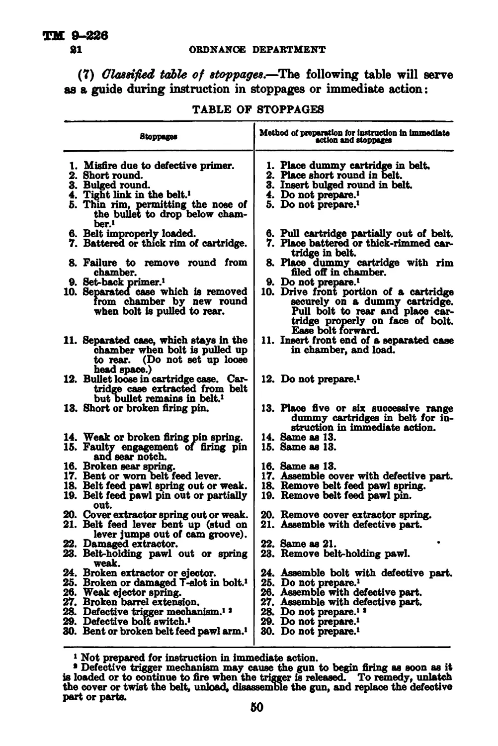
Stoppages______________________________________________ 21
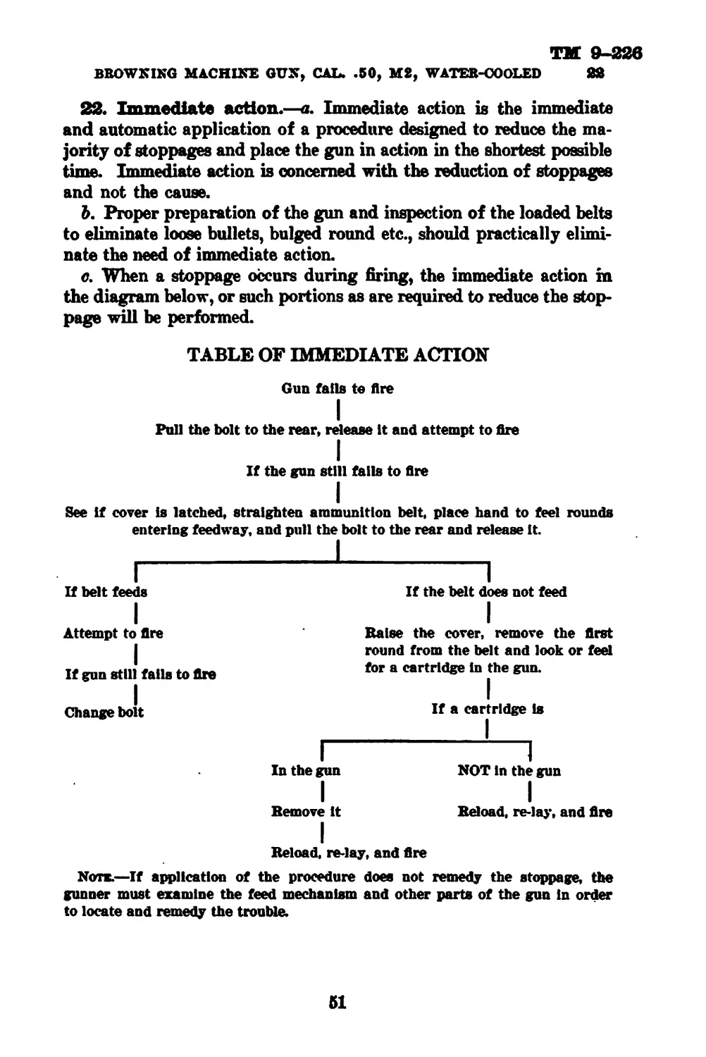
Immediate action______________________________ 22
278864°—41---1
1
TM 9-226
ORDNANCE DEPARTMENT
Section V. Care and preservation.
General______________________________________________________ 23
Points to be observed before, during, and after
firing------------------------------------- 24
Care and cleaning of gun________________________ 25
Method of filling oil buffer___________________ 2fi
Precautions to be observed during cold weather. 27
Precautions to be observed during gas attack____ 28
VL Sighting and fire control equipment.
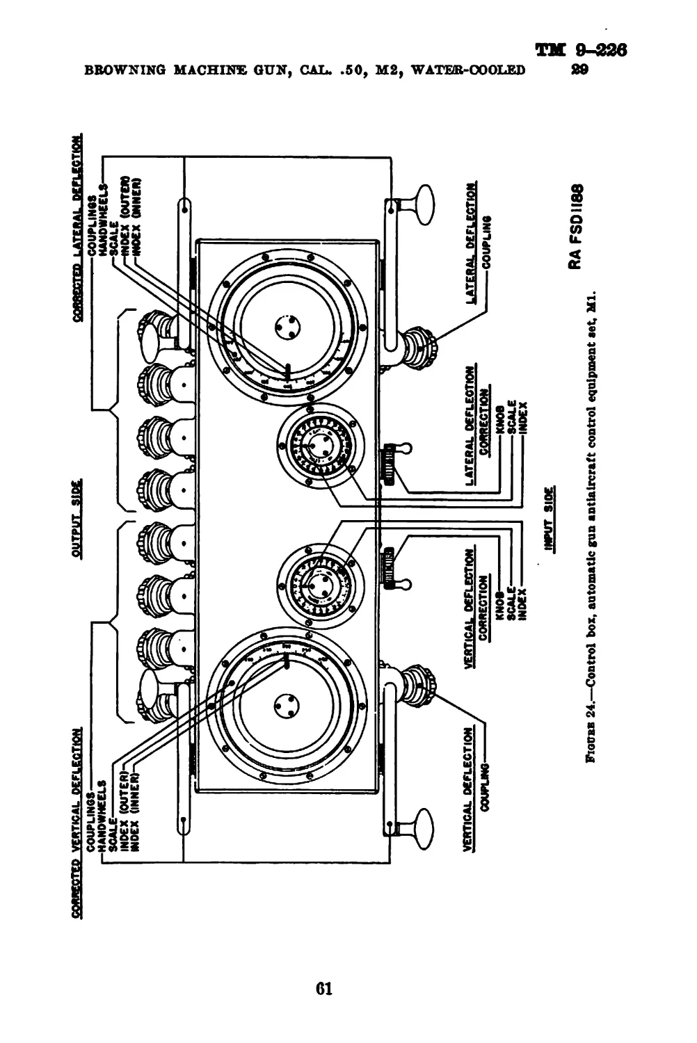
Control equipment set, automatic gun, antiair-
craft, Ml__________________________________ 29
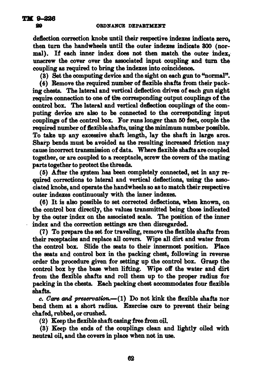
Finder, range, 1-meter base, M1916-------------- 30
VUL Ammunition.
General________________________________________ 31
Nomenclature____________________________________ 32
Classification__________________________________ 33
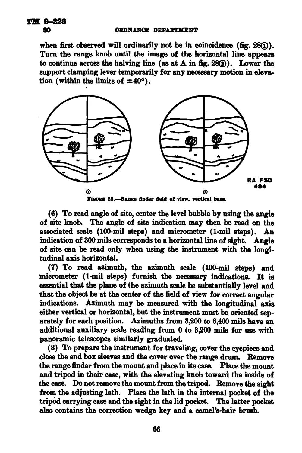
Identification__________________________________ 84
Model___________________________________________ 35
Ammunition lot number--------------------------- 36
Identification card_____________________________ 37
Grade___________________________________________ 38
Marking_________________________________________ 39
Care, preservation, and handling---------------- 40
Storage----------------------------------------- 41
Authorized rounds_______________________________ 42
Data____________________________________________ 43
Precautions in firing blank ammunition--------- 44
Defects found after firing______________________ 45
Field reports of accidents______________________ 46
VIII. Spare parts and accessories.
Spare parts------------------------------------- 47
Accessories_____________________________________ 48
Page
Appendix. List of references__________________________________ 87
8
тм э-22в
BROWNING MACHINE GVN, САЬ. .50, М2, WATER-COOLED 1-4
Section I
GENERAL
Paragraph
Purpoee 1
Scope------------------------------------------------------------------ 2
References_____________________________________________________________ 3
Data------------------------------------------------------------------- 4
Description of machine gun_________________________________________________ 5
Operation of machine gun_____________________________________________________ 6
Description of antiaircraft machine-gun mount, caliber 50, М2________________ 7
Description of antiaircraft machine-gun tripod mount, Ml_____________________ 8
1. Purpose.—This manual is published for the information and
guidance of the using arms and services.
2. Scope.—a, This manual contains all the essential information
of a technical character required by the using arms for the identifica-
tion, use, and care of the particular materiel described. In addition to
describing the weapon and its mounts, it contains all the essential
information required by the using arms to identify, use, and care for
the ammunition, spare parts, and accessories, sighting and fire control
equipment, and cleaning and preserving material
b, The disassembling outlined in this manual is the only disassem-
bling which the using troops are authorized to perform.
3. References.—All manuals to be used in conjunction with this
manual are shown in the Appendix.
4. Data.—a. Machine gun.
Weight of gun with water, 36-inch barrel----------pounds— 110.00
Weight of gun with water, 45-inch barrel------------do----121.50
Weight of gun without water, 36-inch barrel---------do---- 94.00
Weight of gun without water, 45-inch barrel_________do----100.50
Weight of barrel assembly, 36-inch barrel-----------do---- 14.50
Weight of barrel assembly, 45-inch barrel-----------do---- 17.08
Over-all length of gun, 36-inch barrel------------inches— 57.00
Over-all length of gun, 45-inch barrel------------do_— 65.98
Number of grooves in barrel------------------------------- 8
Rate of automatic fire____________________shots/minute— 500-650
8
TH 9-226
4-6
ORDNANCE DEPARTMENT
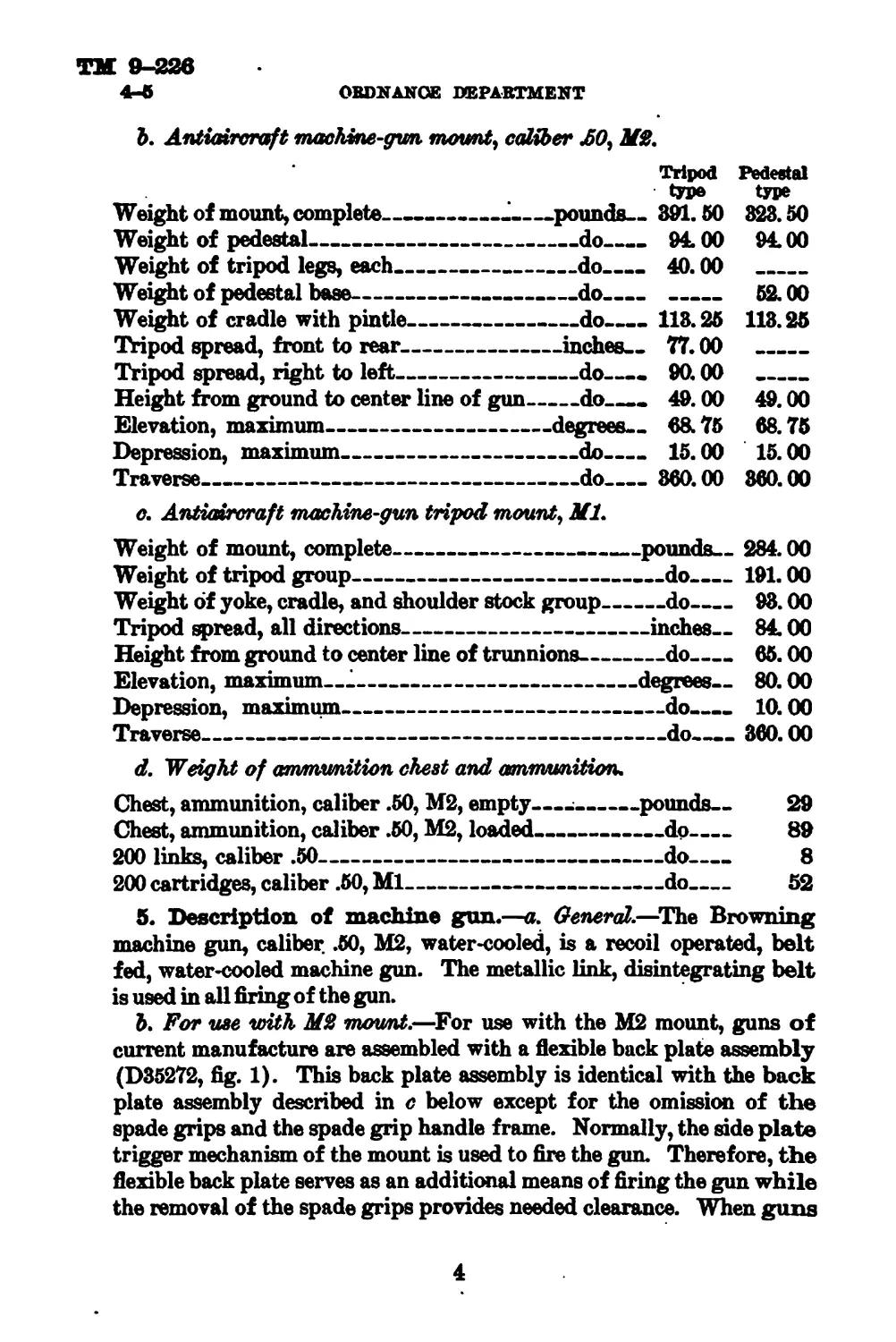
b. Antiaircraft machine-gun mount, caliber AO, MS.
Tripod Pedestal
type type
Weight of mount, complete_______..___’_____pounds— 391.50 323.50
Weight of pedestal--------------------------do---- 94.00 94.00
Weight of tripod legs, each________________do____- 40.00 _
Weight of pedestal base--------------------do.____ _______ 52.00
Weight of cradle with pintle______________do______ 113.25 118.25
Tripod spread, front to rear---------------inches.. 77.00 _______
Tripod spread, right to left---------------do—. 90.00 ___________
Height from ground to center line of gun---do—. 49.00 49.00
Elevation, maximum-----------------------degrees.. 68.75 68.75
Depression, maximum------------------------do.— 15.00 15.00
Traverse___________________________________do_____ 360.00 360.00
c. Antiaircraft machine-gun tripod mount, Ml.
Weight of mount, complete-------------------------pounds.. 284.00
Weight of tripod group----------------------------do______191.00
Weight of yoke, cradle, and shoulder stock group______do.— 93.00
Tripod spread, all directions---------------------inches.. 84.00
Height from ground to center line of trunnions--------do.— 65.00
Elevation, maximum—------------------------------degrees.. 80.00
Depression, maximum---------------------------------do.... 10.00
Traverse______________________________________________do—— 360.00
d. Weight of ammunition chest and ammunition.
Chest, ammunition, caliber .50, М2, empty.—;------pounds— 29
Chest, ammunition, caliber .50, М2, loaded----------do---- 89
200 links, caliber .50------------------------------do---- 8
200 cartridges, caliber .50, Ml---------------------do---- 52
5. Description of machine gun.—a. General.—The Browning
machine gun, caliber .50, М2, water-cooled, is a recoil operated, belt
fed, water-cooled machine gun. The metallic link, disintegrating belt
is used in all firing of the gun.
b. For иле with MS mount.—For use with the М2 mount, guns of
current manufacture are assembled with a flexible back plate assembly
(D35272, fig. 1). This back plate assembly is identical with the back
plate assembly described in c below except for the omission of the
spade grips and the spade grip handle frame. Normally, the side plate
trigger mechanism of the mount is used to fire the gun. Therefore, the
flexible back plate serves as an additional means of firing the gun while
the removal of the spade grips provides needed clearance. When guns
4
Figuu 1.—Browning machine gun, caliber J5O. М2, water-cooled (modified), right aide view,
о
ORD. I074G
Ifiauu 2.—Browning machine gun. caliber Л0. М2, water-cooled, right aide view.
TM 9-226
5
ORDNANCE DEPARTMENT
having spade grips are required for use on the М2 mount, the spade
grips and handle frames should be removed and replaced with upper
and lower filler pieces. If these filler pieces are not available, or time
and/or facilities will not permit of the removal of the handle frame and
the installation of the filler pieces, the handle frame should be cut off
thereby removing these spade grips.
c. For we with Ml mounl.—Guns manufactured prior to current
orders were intended for use on Ml mount, and when so mounted are
fired through the back plate trigger. The spade grips are desirable
but are not essential.
d. Cooling cooling system for the water-cooled ma-
chine gun consists of a water jacket surrounding the barrel and a
water chest with pump. The water jacket of guns with 36-inch bar-
rels contains 8 quarts of water and the 45-inch barrel 10 quarts of
water. The water chest contains approximately 8 gallons of water.
Both the water jacket and the water chest should be kept full at all
times. In an emergency the full water jacket of the gun will permit
cooling for short duration. However, for prolonged fire the water
chest should always be coupled to the gun, and the entire circulating
system kept full of water. The water absorbs the heat generated in
firing the gun and thus prevents the barrel from becoming over-
heated. The steam tube is located in the top of the water jacket and is
free to slide on the front and rear steam tube supports. Each of these
supports is provided with a hole, the rear one being covered by the
steam tube when the gun is elevated and the front one when the gun
is depressed, thus preventing the escape of water from the jacket. The
opposite hole, which is uncovered by this movement, allows the water
and any steam generated through prolonged firing to escape through
the steam tube and the outlet leading to the water supply or the cir-
culating unit where any steam is condensed.
e. Feeding,—By properly repositioning some of the component
parts, the gun may be fed from either the right or left hand feed.
However, this gun when mounted on the tripod mounts must be assem-
bled for left hand feed. A retracting slide is provided which is con-
nected with the bolt by means of the retracting slide bolt stud. The
retracting slide handle remains stationary and in a forward position
while the gun is firing, thus eliminating all moving parts outside of
the receiver.
/. Mounting.—For antiaircraft purposes two mounts may be used:
the antiaircraft machine-gun mount, caliber .50, М2 and the antiair-
craft machine-gun tripod mount, caliber .50, Ml. For detailed de-
scription of these mounts, see paragraphs 7 and 8.
6
ТМ 9-226
BROWNING MACHINS GUN, CAL. .60, М2, WATER-COOLED 5-6
g. Sights.—The gun is equipped with the conventional machine-gun
front and rear sights. (However, the М2 mount is equipped with
sights which permit off-carriage control. For detailed description of
this sight, see paragraph 7.)
(1) Front sight.—The front sight is the conventional blade type
and is protected by the front sight cover.
(2) Combination rear sight.—The combination rear sight is the
conventional leaf type sight. The sight is adjustable for windage.
The drift is offset automatically by the construction of the rear sight
leaf. The wind gage arc on the base is graduated in mils. The leaf
is graduated in yards up to 3,200 yards for caliber .50, Ml ammunition
with a muzzle velocity of 2,400 f/s. New leaf, now under manufacture,
will be graduated for ammunition of 2,660 f/s muzzle velocity. Cali-
bration of the sight leaf for ammunition of different muzzle velocities
'may be obtained by the use of the elevating screw which raises or
lowers the slide 1 mil. By pressing in the half nut, instantaneous
adjustment of the slide can be accomplished.
h. Recoil mechwism.—knoil buffer mechanism in the gun cushions
the force of the recoiling part. The М2 mount includes a recoil mech-
anism of the spring type which absorbs the recoil of the gun and also a
counterrecoil mechanism which absorbs the force of the recoil spring
when the gun is returned to firing position. For further description
of this recoil mechanism, see paragraph 7.
6. Operation of machine gun.—Operation as discussed herein
is divided into two sections:
a. Manual operation.—Manual operation is that operation performed
by the gunner.
(1) To load—Loading may be considered to include two distinct
operations; entering the loaded belt properly into the belt opening,
and thereafter operating the mechanism of the gun until it is closed
with the cartridge in the chamber and a cartridge in the feedway
gripped by the extractor for extraction on the next recoil stroke. The
double loop end of metallic link belt should always be inserted regard-
less of whether right or left hand feed is employed.
(a) The first of these operations may be performed with the cover
either open or closed. In either case, enter the double loop end of the
belt through the feed opening until the first cartridge is beyond the
belt holding pawl. Close the cover, if open. Pull the bolt com-
pletely to the rear by means of the retracting slide and release it.
(5) The second operation consists of pulling the bolt once com-
pletely to the rear and then allowing it to spring forward. This opera-
7
так 9-226
О ORDNANCE DEPARTMENT
tion must start with the action fully closed and the extractor gripping
the cartridge in the feedway.
(2) To unload.—(a) Lift cover, remove belt, retract bolt, and make
visual inspection of feed way, T-slot, and chamber to make certain that
gun is unloaded.
(b) Release bolt and lower cover.
(c) Press trigger or sear mechanism to relieve tension on firing pin
spring.
b. Mechanical operation,—Mechanical operation is that operation
which is automatically performed by the gun itself when fired. The
following explanation of mechanical operation begins with the gun
assumed to be loaded and ready to fire. This explanation covers the
mechanical operation of the gun itself. When fired from the anti-
aircraft machine gun mount, caliber Л0, М2, the recoil mecha-
nism of the mount affects to a slight degree the mechanical operation
described herein (see par. 7).
(1) Side plate trigger action on first shot.—When the side plate
trigger slide is pulled to the rear the action of the side plate trigger
cam forces the sear slide inward. This in turn forces the sear down-
ward, releasing the sear notch from the shoulder of the firing pin.
The firing pin spring forces the firing pin forward to fire the cartridge.
(2) Back plate trigger action on first shot.—W^&n the rear end of
the trigger, which is pivoted in the center, is pressed down, its forward
end pushes up the rear end of the trigger bar; the trigger bar being
pivoted in the center acts as a lever and causes the front end to press
down upon the top of the sear, forcing the sear down and releasing
the sear notch from the shoulder of the firing pin. The firing pin
spring forces the firing pin forward to fire the cartridge.
(8) Backward movement of recoiling parts.—The explosion of the
cartridge forces the barrel to the rear, carrying with it the barrel
extension and the bolt which is locked to the barrel extension by the
breech lock. When the barrel has recoiled about % inch, the breech
lock pin strikes the cam surfaces of the breech lock depressors. This
unlocks the bolt from the barrel extension and permits the bolt to
continue to the rear. As the barrel extension moves to the rear it
strikes the accelerator and turns it backward.
(4) Backward action of accelerator.—As the accelerator turns back-
ward it strikes the bottom projection on the bolt and accelerates it to
the rear. The shoulders on the barrel extension shank engage behind
the claws of the accelerator, locking the barrel and barrel extension
in a rearmost position to the oil buffer body.
8
TM 9-226
BROWNING MACHINE GUN, CAL. .50, М2, WATER-COOLED 6
(5) Backward movement of bolt.—As the bolt moves backward the
driving spring is compressed. The bolt brings with it a cartridge
from the belt gripped by the extractor and an empty case from the
chamber gripped in the T-slot The cam lug on the extractor rides
along on top of the switch until near the end of the backward move-
ment of the bolt Then the extractor by action of the cover extractor
cam is forced downward until its cam lug is below the switch.
(6) Action of oil buffer.—As the barrel and barrel extension move
backward together, the oil buffer spring is compressed, since the oil
buffer piston rod is linked directly with the barrel extension by means
of the hook on the shank projecting from the rear of the barrel exten-
sion and the hook on the forward end of the oil buffer piston rod; the
oil buffer piston rod head and the oil buffer piston valve are driven
rearward in the oil buffer tube forcing the oil through the restricted
openings in both the piston rod head and valve. This supplements
the action of the oil buffer spring in bringing the heavy recoiling parts
to rest without damaging shock or strain on the gun. On the counter-
recoil or forward movement of the barrel and barrel extension, the oil
in front of the piston rod head will force back the piston valve, uncover-
ing the openings and permitting the oil to pass readily from the for-
ward to the rear side of the piston rod head and valve, thus permitting
the rapid return of the parts to the firing position.
(7) First action of feeding.—As the bolt moves backward, the stud
on the belt feed lever riding in its cam groove in the top of the bolt
moves the belt feed pawl laterally into position behind the next cart-
ridge. The ammunition belt is prevented from falling out of the gun
by the belt holding pawl.
(8) Cocking action.—As the bolt moves backward, the upper end
of the cocking lever is forced forward by the top plate bracket attached
to the top plate, which brings the lower end of the cocking lever to the
rear. When the lower end of the cocking lever moves to the rear it
brings with it the firing pin, withdrawing the firing pin from the face
of the bolt and compressing the firing pin spring against the sear stop
pin. The shoulder of the firing pin engages in the notch in the sear
under pressure of the sear spring.
(9) Action of driving spring.—When the rear end of the bolt strikes
the buffer plate, its remaining force is absorbed in the fiber buffer disks.
The driving spring which has been compressed by the backward action
of the bolt then forces the bolt forward. On guns manufactured after
June 1940, two driving springs, one inside the other and wound in
opposite directions, are used. By the use of two springs, greater initial
spring load is provided which is an advantage in feeding ammunition
278864°—41---2
9
ТМ 9-226
О OBDNANOE DEPARTMENT
during high angles of fire. The new assembly will be available for
replacement of old type assemblies now in service.
(10) Forward movement of bolt.—When the bolt starts forward the
cam lug on the extractor riding under the switch rotates the extractor
downward. This causes the extractor to force the cartridge down the
T-slot in line with the chamber. The ejector knocks the empty cape
from the T-slot and holds the cartridge in line with the chamber.
(The empty case may have already fallen out without the action of
the ejector.) The upper end of the cocking lever is forced backward
and the lower end moves forward away from the rear of the firing pin.
(11) Release of recoiling parte.—The lug on the lower rear end of
the bolt strikes the accelerator and rotates it forward. This unlocks
the barrel extension from the oil buffer body. The barrel extension
remains linked with the oil buffer piston rod. (See (6) above.) When
the accelerator has been tripped the barrel extension and the barrel
move forward, assisted by the oil buffer spring. Part of the for-
ward force of the bolt acts through the accelerator to push the barrel
extension forward.
(12) Loading and locking action,—The extractor rises as its cam
lug moves along the top of the extractor cam and the ejector moves
outward, leaving the cartridge in the chamber engaged by the T-slot.
The extractor grips the first round in the belt and is held down firmly,
ready to extract it, by the cover extractor spring. The breech lock is
forced upward by the breech lock cam and locks the breech just before
the recoiling parts reach the firing position. (The breech lock engages
in a recess cut in the bottom of the bolt and thus locks it firmly to the
barrel extension and against the rear end of the barrel.)
(18) Second action of feeding.—As the bolt goes forward, the stud
on the end of the belt feed lever riding in its cam groove in the top
of the bolt moves the belt feed slide and belt feed pawl in a lateral
direction. The belt feed pawl carries the first cartridge against the
cartridge stops, ready to be gripped by the extractor. The next car-
tridge is carried over the belt holding pawl, which rises behind it and
holds it in position to be engaged by the belt feed pawl on its return
movement.
(14) Trigger action in automatic fire.—If the hand trigger is held
down, the sear is disengaged just before the bolt has reached its for-
ward position, thereby releasing the firing pin. The gun thus fires
automatically, repeating the operation of functioning already de-
scribed. (The release of the firing pin actually takes place when
the recoiling parts are still about % inch from the forward position
but after the breech is locked.) When the firing lever of the М2
10
ТМ 9-226
BROWNING MACHINE GUN, CAL. .60, М2, WATER-COOLED 6-7
mount is depressed, the trigger control mechanism acts through the
side plate trigger and the sear slide in the bolt to disengage the sear
from the firing pin, thereby igniting the cartridge. The reaction
from firing causes the gun to recoil in the cradle. During counterre-
coil the lug on the side plate trigger engages the mating lug of the
trigger control, the sear is disengaged, and another cartridge is
ignited. During this cycle the gun is fired semiautomatically.
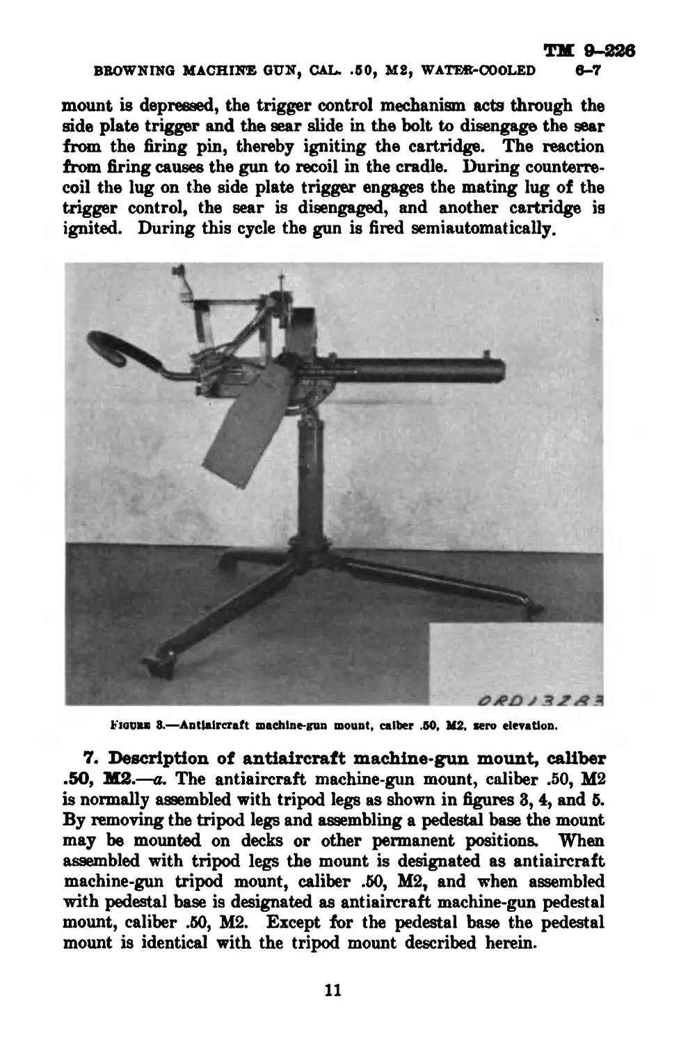
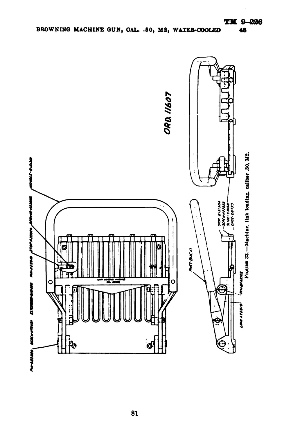
Fiotnuo 8.—Antiaircraft machine-gun mount, calber .50, М2, aero elevation.
7. Description of antiaircraft machine-gun mount, caliber
•50, М2.—a. The antiaircraft machine-gun mount, caliber .50, М2
is normally assembled with tripod legs as shown in figures 3, 4, and 5.
By removing the tripod legs and assembling a pedestal base the mount
may be mounted on decks or other permanent positions. When
assembled with tripod legs the mount is designated as antiaircraft
machine-gun tripod mount, caliber .50, М2, and when assembled
with pedestal base is designated as antiaircraft machine-gun pedestal
mount, caliber .50, М2. Except for the pedestal base the pedestal
mount is identical with the tripod mount described herein.
11
TM 9-226
7
ORDNANCE DEPARTMENT
b. The antiaircraft machine-gun tripod mount, caliber .50, М2
(fig. 5) consists principally of the pedestal (4), tripod legs (5),
cradle (2), pintle (8), back rest (6), sight support (7), and the rear
sight (8), and front right (2fi) assemblies. The lever of the trigger
control mechanism is indicated at (27) and a safety lock at (29).
(1) Tripod (fig. 5).—The tripod is composed of the pedestal and
the tripod legs.
Figure 4.—Antiaircraft machine-gun mount, caliber .50, М2, maximum elevation.
(a) Pedestal.
1. The pedestal is a seamless steel tubing body lined with
bronze bushing (9) (forced in place) which forms the
seat for the cradle pintle. The lower portion of the
pedestal is assembled with the pedestal base support
ring (10) welded in place. The ring (10) is threaded
to fit the removable hook (11) provided to hold down
and stabilize the tripod on a hard base or in a truck.
The pedestal is designed to be mounted on a pedestal
12
ТМ 9-226
BROWNING MACHINS GUN, CAL. .50, М2, WATER-COOLED 7
base assembly in certain applications in which the tripod
legs are not used, such as deck mounts for Army mine
planters.
2. The base ring (12) welded to the pedestal body forms the
connection of the pedestal with the tripod legs. The leg
clamping ring (13) is threaded to fit the base ring and is
used to lock the tripod legs in firing position. Tapered
ring (14) of the clamping ring assembly engages a mat-
ing lug (21) on head (17) of each tripod leg, drawing the
latter into place when the clamping ring is screwed down.
3. The pedestal lock assembly is composed of a spring actuated
plunger (15) which engages a mating groove in the pintle
and retains the latter in firing position. Cam lever (16)
withdraws the plunger when the lever is placed in hori-
zontal position, thereby permitting removal of the pintle
from the pedestal.
13
ТМ 9-226
7
ORDNANCE DEPARTMENT
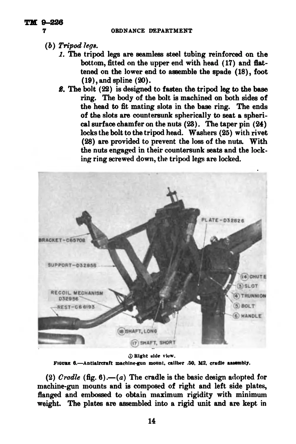
(&) Tripod legs.
1. The tripod legs are seamless steel tubing reinforced on the
bottom, fitted on the upper end with head (17) and flat-
tened on the lower end to assemble the spade (18), foot
(19), and spline (20).
£ The bolt (22) is designed to fasten the tripod leg to the base
ring. The body of the bolt is machined on both sides of
the head to fit mating slots in the base ring. The ends
of the slots are countersunk spherically to seat a spheri-
cal surface chamfer on the nuts (23). The taper pin (24)
locks the bolt to the tripod head. Washers (25) with rivet
(28) are provided to prevent the loss of the nuts. With
the nuts engaged in their countersunk seats and the lock-
ing ring screwed down, the tripod legs are locked.
Q Bight bide view.
Fiqubk 6.—Antiaircraft
machine-gun mount, caliber .50, М2, cradle assembly.
(2) Cradle (fig. 6).—(a) The cradle is the basic design adopted for
machine-gun mounts and is composed of right and left side plates,
flanged and embossed to obtain maximum rigidity with minimum
weight. The plates are assembled into a rigid unit and are kept in
14
TM 9-22в
BROWNING MACHINE GUN, CAL. .60, М2, WATEIR-OOOLED 7
©Top view.
© Left side view.
15
ТМ 9-226
7 ORDNANCE DEPARTMENT
alinement by the construction of the cradle pintle (1), the box type con-
struction of the frame which houses the recoil mechanism, and by
shouldered spacer bolts. The ammunition box support (2) is as-
sembled to the left cradle plate.
(&) The cradle pivots for movement of the gun in elevation and
depression are controlled by the length of the cradle slots (3) on
trunnion studs (4) mounted on the pintle, and are clamped to the
pintle by bolt (5) with cradle clamping handle (6).
(c) The machine gun is assembled to the cradle by the gun trunnions
seated in the trunnion slide indicated at (7) and is locked in this posi-
tion by the hinged caps (8) clamped by thumb nuts (9). The breech
end of the gun is secured to the cradle by the rear gun joint pin (10)
through the gun bracket and the slide of the recoil mechanism. If
difficulty is experienced in lining up the gun bracket and the slide of
the recoil mechanism to insert the joint pin, the joint pin should be
inserted before the gun trunnions are seated in the trunnion slide.
After the joint pin is inserted, the gun may be pulled forward against
the action of the recoil spring and the trunnions pushed down into the
recesses in the trunnion slide.
(<f) The back rest (11) is adjustable and clamped in position by
cap screws (12). The sight support is bolted to the cradle by cap
screws (18). The rear sight assembly is indicated at (16). The flex-
ible cable connection for adjustment of the front sight in elevation is
attached at (17) and for adjustment in azimuth at (18). The caps
shown are provided for protection of the terminals when the cables
are not in use.
(e) The side plate trigger container is composed of body (19), cap
(20), and chain (21), fastened to left side of the cradle. The cap has
two pins 180° apart which mate with two slots in the open end of
body (19). To remove the cap, press cap (20), turn counterclockwise,
and pull apart. To assemble, reverse the above order.
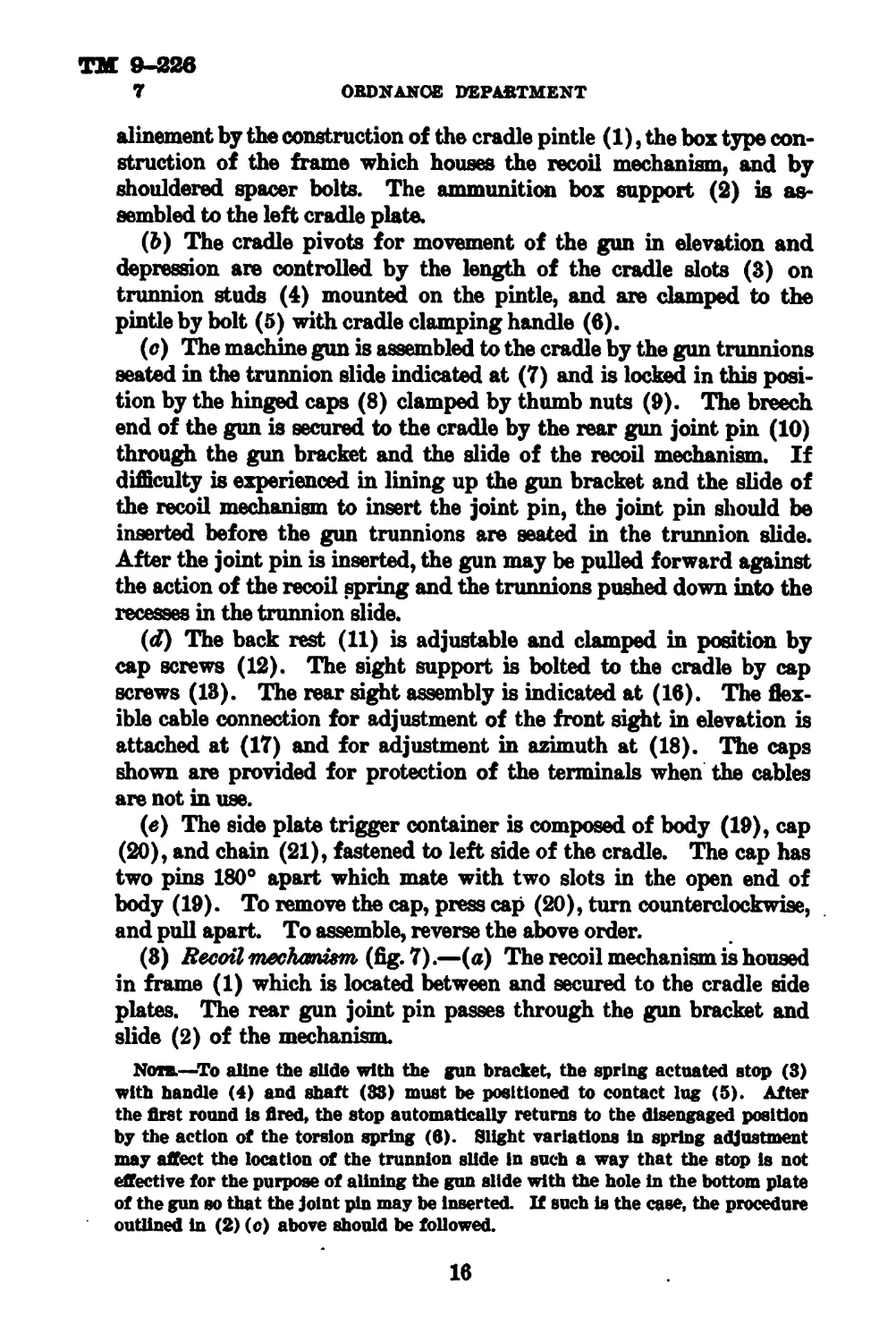
(8) Recoil tnwhaniem, (fig. 7).—(a) The recoil mechanism is housed
in frame (1) which is located between and secured to the cradle side
plates. The rear gun joint pin passes through the gun bracket and
slide (2) of the mechanism.
Non.—-To aline the slide with the gun bracket, the spring actuated stop (3)
with handle (4) and shaft (33) must be positioned to contact lug (5). After
the first round is fired, the stop automatically returns to the disengaged position
by the action of the torsion spring (6). Slight variations in spring adjustment
may affect the location of the trunnion slide in such a way that the stop is not
effective for the purpose of alining the gun slide with the hole in the bottom plate
of the gun so that the joint pin may be inserted. If such is the case, the procedure
outlined in (2) (o) above should be followed.
16
*08812
Fromm 7.—Antiaircraft machine-gun mount, caliber .50, М2, recoil mechanism.
QftD. /3277
ТМ 9-22в
7
OBDNANOE DEPARTMENT
(b) The lower recoil mechanism assembly is composed of bearing
(7) secured to the frame by nuts (12) and machined to allow a slide
fit for slide (2). The bearing houses the recoil spring (8) in addi-
tion to head (9), which mounts rod (10) provided to guide the com-
ponent spring (11). The spring (11) compensates for the com-
ponent weight of the machine gun between zero and maximum
elevation.
(c) The recoil spring (8) is retained between the slide (2) and nut
(13). The component spring (11) is seated between head (9) and
threaded plug (16). The plug is provided for adjusting the tension
of the spring and is locked by nut (16).
(d) The two upper recoil springs (32) are assembled on shaft
(14) to the rear of the slide (25) which carries the trunnion bearing.
Front guide (26) is placed in front of spring (32) and the rear guide
(27) at the rear of the spring (32).
Note.—These springs do not require any adjustment. The guides must be
lubricated.
(4) Operation of recoil meckaniem (fig. 7).—As the machine gun
recoils, slide (2) moves with the gun to the rear, compressing springs
(8), (11), and (32). The built-up spring pressure brings the gun
to rest at the end of recoil and returns it to battery during counter-
recoil. The counterrecoil of the gun is retarded by the counterrecoil
springs (17). The firing mechanism is so arranged that the gun
cannot be fired until it reaches a predetermined point in the path
of counterrecoil, which is determined by the location of the lug which
contacts the side plate trigger. Whether the gun is fired when it
reaches this point or later depends on the relation of the moving
parts of the gun mechanism, that is, the sear slide must be in position
to be disengaged by the side plate trigger. The counterrecoil force
of the gun is finally checked by the impulse of this shot When firing
a single shot and on the last shot, the counterrecoil spring absorbs the
final energy of counterrecoil
(5) Adfatrnent of recoil mechanism (fig. 7)^—(a) The plug (28)
should be 6Д inches from the forward rear face of bracket (31) and
lock nut . (30) locked against it Screwing in the plug checks the gun
earlier in counterrecoil and will disturb the smoothness of firing if
screwed in more than a few turns (clockwise). Unscrewing the plug
(counterclockwise) reduces the counterrecoil spring load and aids
smoothness of action. However, caution is necessary due to unavoid-
able variation in energy of cartridge, friction in links, pull, etc. The
gun must not be allowed to come in battery, metal to metal with the
forward rear face of bracket (31) and the front of slide (25).
18
ТМ 9-&6в
BROWNING MACHINE GUN, CAL. .60, М2, WATER-COOLED 7
(b) The constant recoil is obtained by the compensating spring
which is acting on three planetary gears and racks. Gear (18) is se-
cured to the cradle pintle and meshes into gear (20) which pivots on
the cradle and meshes into rack (22).
(<?) The mechanism is adjusted for normal recoil of the machine gun
at zero elevation. As the gun is elevated, gears (20) rotate on gears (18)
and pull racks (22) attached to head (9) forward. This movement
compresses the compensating spring and maintains normal recoiL
(d) During depression of the machine gun from zero elevation, no
change takes place in the spring adjustment, and the movement of the
gears and racks is compensated by the extended turned surface (9)
in the space between the nut and shoulder of the rack.
(e) To adjust lower recoil spring (8).—Remove nuts on racks (22),
plate (24), head (9), rod (10), and spring (11). The normal adjust-
ment of recoil spring (8) is made by setting the rear of nut (13) 4%
inches from the rear end of bearing (7). Make sure the measurement
is taken from the rear of the nut (18) and not from the bottom of the
wrench slot which is Д inch deep. Each complete clockwise turn of
nut (18) increases the compression of the spring approximately 8%
pounds. Assemble spring (11), head (9), rod (10), plate (24), and the
nuts on the racks (22).
Caution.—Do not place nut (13) closer to the end of the recoil
spring housing than 4% inches (normal setting). This prevents a
metal to metal contact at maximum elevation. This setting gives
full adjustment forward for the spring reserve. This spring has
a stress below 80/XX) pounds per square inch and should require little
if any adjustment. The spring must be cleaned occasionally and,
unless plated, must be covered with a light grease to prevent
corrosion.
(/) To adjust component spring (11).—The plug (15) should be
flush with lock nut (16). The latter must be tightened and be
secured by the lockwasher bent slightly into the wrench slot. No
further adjustment is required normally.
(^) Lubricate slides (2) and (25) frequently through the oil
hole provided in the top of the slide with a light lubricating oil,
Navy contract No. 2110 (equivalent to SAE 10, 90-120 viscosity at
130° F.).
(Л) Match marks are provided for correct assembly of gears (18)
and (20) and proper caution must be exercised when removing the
springs in order to avoid possible injury to personnel.
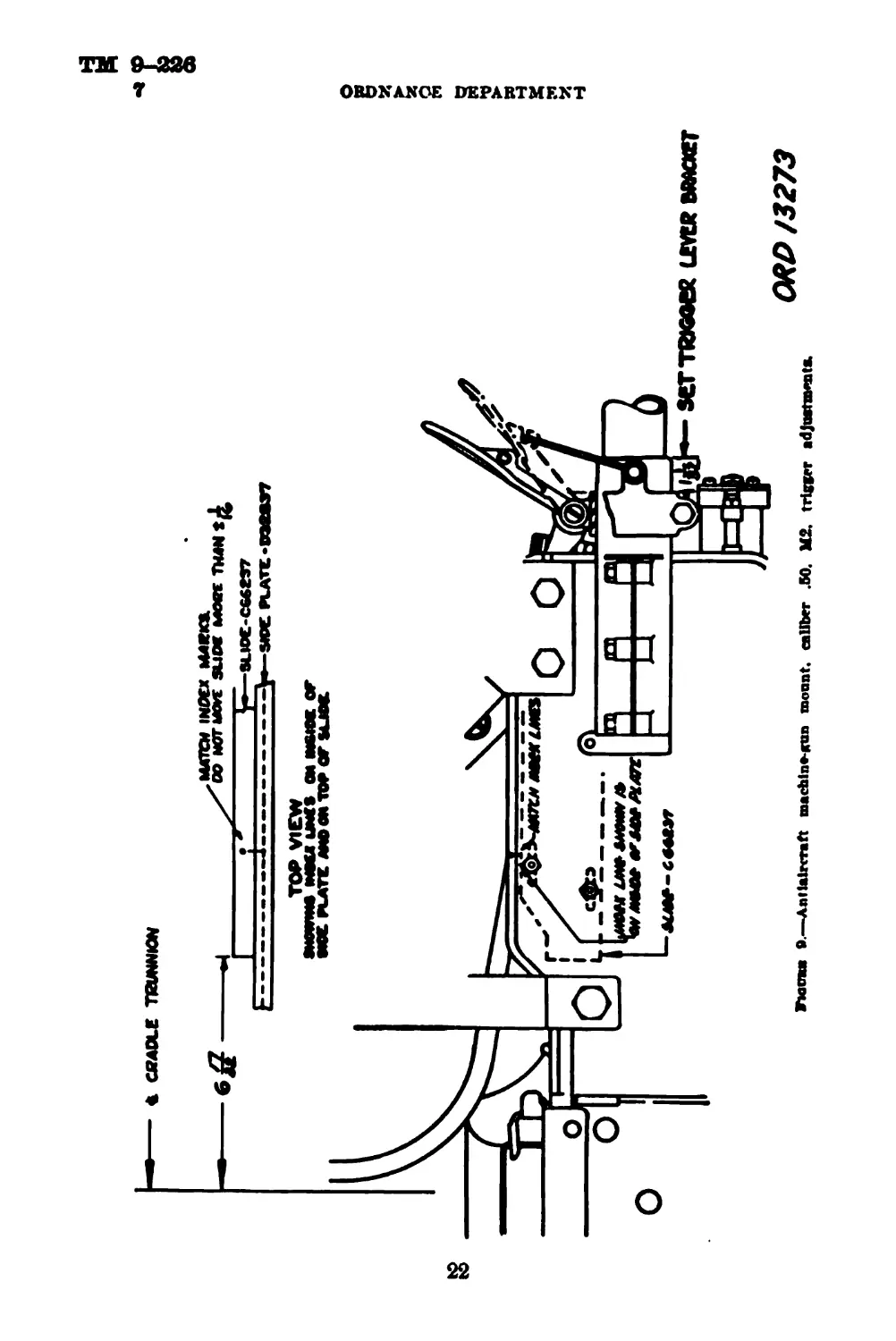
(6) Trigger control mechanism (fig. 8).—This mechanism is shown
in the disengaged position.
19
ТМ 9-226
7
ORDNANCE DEPARTMENT
(a) Lever (1) is mounted on the bracket (2) which clamps to the
back rest bracket indicated at (3). When firing, lever (1) is pushed
down to rest on the back rest. In this position, slide (4) is pulled
to the rear and with it, by contact with lug (5), the side plate
trigger slide on the machine gun which operates the firing mechanism
of the weapon. Coil spring (6) is provided to absorb the trigger
firing load during automatic firing, which would otherwise be trans*
mitted to the lever. It also provides a yieldable connection to fire
the first shot and then timed automatic firing. Coil spring (7) in
addition to the torsion spring (8) will return the mechanism to dis*
engaged position when the lever is released, and return the side
plate trigger slide to the neutral position.
Fioubi 8.—Antiaircraft machine-gun mount, caliber .50, М2, trigger control mechanism.
(b) The rear of the hand trigger bracket (2) should be set inches
from the rear of the back rest bracket (3) also shown on figure 9.
This setting should not be changed more than 7? inch to front or rear.
The trigger side plate is located by matching the index lines on the
slide, C66237, and side plate, D32837. This setting also should be
within 7r inch. Incorrect setting of either the bracket (2) or slide,
C66237, places unnecessary load on spring (6) and side plate trigger
lever spring (8), as well as on the linkage (fig. 8). To move bracket
(2) forward loses some of the preferable throw. Move the bracket
the same amount as slide, C06237, (fig. 9) if the adjustment is changed.
20
TM 9-226
BROWNING MACHINS GUN, GAL. .60, М2, WATER-COOLED 7
(<?) Safety lock (18) (fig. 8) is provided to lock the firing mech-
anism and is shown with the firing mechanism in the “safe” posi-
tion. To fire, pull down the safety lock.
(7) Sight assemblies (fig. 10).—(a) Rear sight.
1. The rear sight is mounted on bracket (4) which is secured
in clamp (20) of the sight support. The bracket is pro-
vided with hinged cap (3), secured by the spring actu-
ated pin (5) engaging a mating detent. To open the cap,
pull down on knob (6). Pin (7) is provided for locating
the rear sight assembly on the bracket
8. The body (15) of the rear sight mounts on the rotatable disk
(16), provided with -ft, %, A, and % inch peepholes,
which can each be brought in line with the front sight.
Each adjustment is secured in position by the spring
actuated pin (17) engaging a slot cut in the periphery
of the disk. A slight vertical and horizontal adjustment
is provided by means of an adapter. Adjustment of the
adapter is obtained by removing three screws (18) which
fasten the adapter (with shield) to the body, and reposi-
tioning the adapter in relation to the body (15) and insert-
ing the screws. The front sight (19) is mounted on the
elevating screw of the front sight assembly.
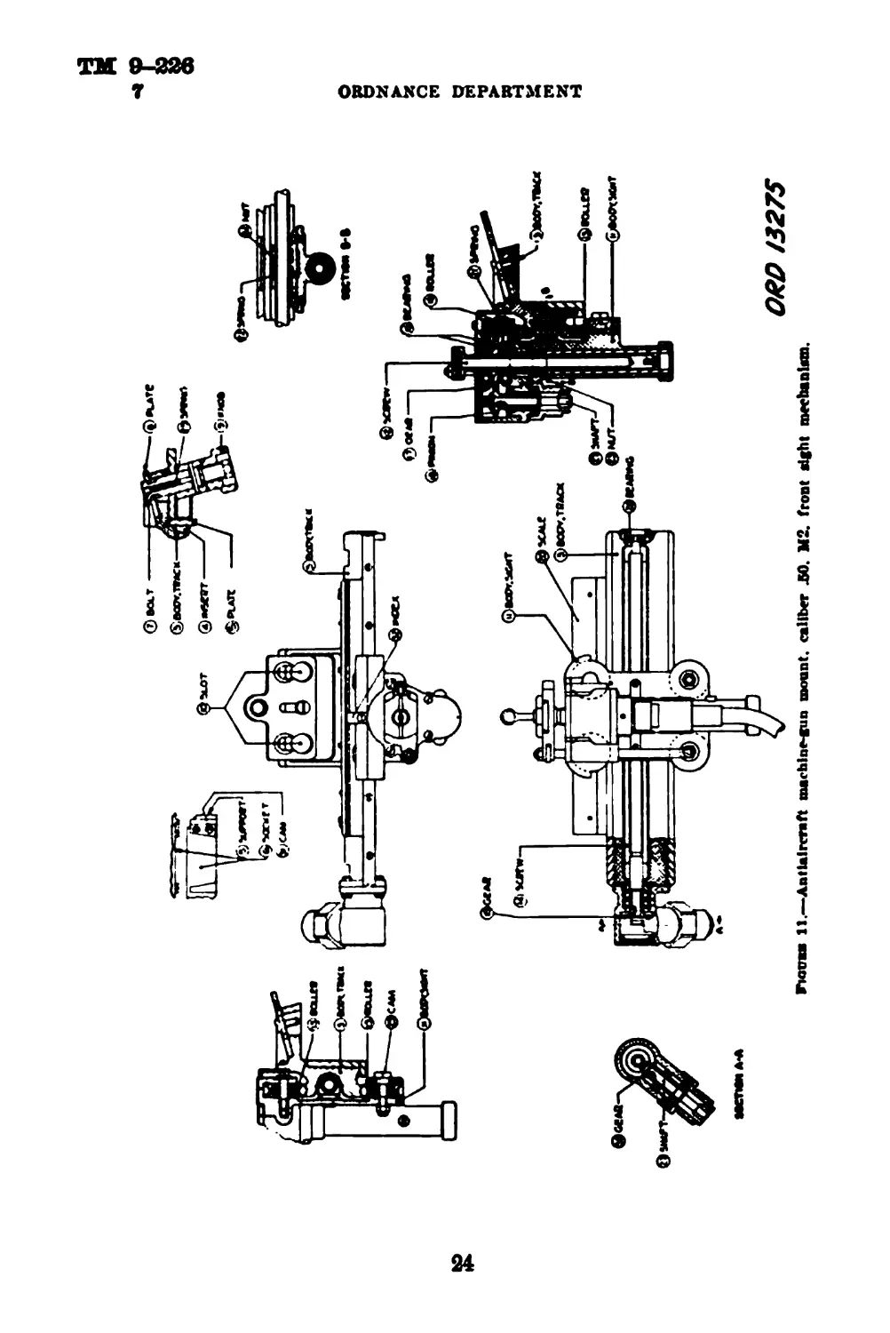
(b) Front sight (fig. 11).
1. The front sight is automatically adjusted from an off-carriage
control station by means of flexible shaft cables con-
nected with the front sight mechanism for elevation and
for traverse. The flexible shaft cables are equipped with
male couplings on the drive shaft, engaging female
couplings on the casings. For further description of the
off-carriage control, see section VI.
Note.—The metallic casing has a tendency to shrink tinder ordinary usage due
to flexing in handling, causing the shaft to become longer than the casing and, if
forced back into the casing by the coupling, tends to buckle and increase friction.
Caution should be taken against unnecessary handling. Sliding connections are
provided for the drive shaft couplings.
£ The aluminum front sight track body (3) with steel insert
(4) is mounted on the sight support (5) with the steel
insert on the body engaging the dovetailed front sight
socket (6). The body is located by locking bolts (7)
engaging mating holes in the body and is secured by
plate (8) drawn down by threaded knobs (9).
21
Fuitraa ®.—Antiaircraft machina-Run mount, caliber .50. М2, trigger adjustments.
ORDNANCE DEPARTMENT
ORD/3273
Fkjuu 10.—Antiaircraft machine-gun mount, caliber .50, М2, eight ааметЬПем.
ТМ 9-22в
7
ORDNANCE DEPARTMENT
11.—Antiaircraft machine-gun mount, caliber Л0. 112. front sight mechanhm.
24
ТМ 9-226
BROWNING MACHINE GUN, CAL. .50, М2, WATER-COOLED 7
3, Plate (8) is provided with elongated slots (10) on one end,
with a countersunk seat on the other end to seat the heads
of bolts (7).
4- When removing the front sight mechanism, release knobs
(9). This causes the spring actuated bolts to rise and
release the plate. Push the plate in position so the body
holes will permit raising the body off the bolts and out
of the dovetail
6. The front sight body (11) houses the front sight elevating
screw (12) and moves in traverse on the front sight track
body (3) on steel insert rollers (18). Traverse is by
means of the ball bearing mounted traversing screw (14)
driven by the flexible cable through a bevel gear drive
(15). Index (82) travels along horizontal scale (20).
6. The front sight elevating screw (12) is mounted on ball bear-
ings (16) and is raised and lowered by the internally
threaded gear (17) driven by pinion (18) which in turn
is driven by the flexible cable from the off-carriage sta-
tion. The head of the elevating screw is flattened on
both sides and machined with an undercut to seat the
front sight. Attached to the elevating screw is an ad-
justable scale.
7. To assemble the sight to the elevating screw, place the sight
with the flat at right angles to the flat on the screw head
and turn the sight 90° in the undercut until the spring
actuated plunger in the elevating screw head engages a
mating detent in the sight.
Note.—Each graduation on the elevating scale and the traversing scale indi-
cates a 1-mil change in elevation or traverse respectively of the machine gun.
c. When converting the tripod mount into a pedestal mount, the
tripod legs are removed and the pedestal is mounted on the pedestal
base. The pedestal base is located by the projection on the base fitting
the mating recess on the pedestal base support ring and is secured to
the pedestal by three eyebolts. The pedestal base is threaded left hand
in three places. These three places contain sleeve nuts in which the
eyebolts are assembled. These eyebolts fit into the lugs from which
the tripod legs were removed. Bolts inserted through the lugs and
eyes of the eyebolts complete the assembly. The pedestal is firmly
secured to the pedestal base by turning the sleeve nut to tighten the
eyebolts. The eyebolts should be tightened uniformly to assure ac-
curate seating of the pedestal in the pedestal base.
273864*—41----4
25
ТМ 9-226
8
ORDNANCE DEPARTMENT
8. Description of antiaircraft machine-gun tripod mount,
Ml (fig. 12).—The mount is of the tripod type in which the cradle
and yoke are supported on a center support so that the gun can be
freely moved by hand in azimuth through 860°. All positions of ele-
vation are allowed from approximately 10° depression to 80° elevation.
Figurk 12.—Antiaircraft machine-gun tripod mount, Ml.
A shoulder stock known as the shoulder stock, М2, is considered a part
of the tripod mount and is provided for the purpose of assisting the
gunner in steadying the gun in antiaircraft fire. When the locking
handle is unscrewed a part turn, the adjusting bracket is free to slide
on the center support, permitting the tripod legs and lower braces to
be folded.
26
TM 9-226
BROWNING MACHINE GUN, (ML. .50, М2, WATER-COOLED 0-11
Section П
DISASSEMBLY, ASSEMBLY, AND HEAD SPACE
Paragraph
General______—.____________________________________________________ 9
Removal of groups from gun----------------------------------------- 10
Replacing groups in gun-------------------------------------------- 11
Head apace------------------------------------------------------- 12
Disassembling------------------------------------------------------ 18
Assembling__________________________________________________________14
Packing barrel----------------------------------------------------- 15
Changing barrels--------------------------------------------------- 10
9. General.—a. The following disassembling is the only disassem-
bling authorized for using troops for the care, cleaning, and replacing
of parts.
b. In removing springs caution should be exercised to avoid injury
to personnel and damage to parts. When loosening parts which hold
springs under tension keep personnel not directly engaged in the
operation dear of the path the suddenly released spring might take.
10. Removal of groups from gun.—a. Cover—Release cover
latch and open cover. The cover need not be removed as the other
parts of the gun may be taken out without removing it
Non.—Removal of the cover group is not recommended unless necessary for
repair as it is difficult to reassemble due to the force required to compress the
detent pawl spring.
b. Back plate.—Release back plate latch lock and back plate latch
and lift out back plate.
o. Balt group.-^xxss forward and away from the side plate on end
of driving spring rod to release the retaining pin in head of rod from
the hole in the side plate. Remove driving spring rod. Draw bolt to
the rear until the bolt stud is in line with the hole in center of slot
in the side plate. Remove bolt stud from bolt Remove the bolt,
complete, out of the rear end of the gun casing.
Ой buffer.—Compress oil buffer body spring lock, using a car-
tridge point or a drift through the hole in the right hand side plate.
Remove oil buffer, barrel extension, and barrel assembly by pulling
out to the rear. Detach oil buffer assembly from barrel extension by
pressing the accelerator forward.
11. Replacing groups in gun.—a. Hold barrel and barrel ex-
tension in the left hand and oil buffer assembly in the right hand.
With the index finger holding the accelerator up under the barrel
extension shank, start the breech block depressors into the guideways
in the barrel extension and press forward, allowing the shank of barrel
2T
ТМ 9-226
11-12 . ORDNANCE DEPARTMENT
extension to engage in the cross groove of the piston rod. Push for-
ward as far as the oil buffer will go, having the accelerator back as
far as possible. This will lock these components together so that the
barrel, barrel extension, and oil buffer assembly may be placed in the
casing of the gun as a unit. Push this unit forward in the casing
until the lock of the oil buffer seats in the recess in the side plate.
b. Press cocking lever forward in bolt and insert bolt into the casing.
Push bolt forward until the hole for the bolt stud is in line with the
enlarged opening in center of slot in the side plate. Insert bolt stud in
bolt, being sure that the collar on the bolt stud is inside the side plate.
Push bolt completely forward guiding the extractor from the front
with the fingers to prevent it from catching.
<?. Insert driving spring rod assembly into the hole m bolt Engage
driving spring rod retaining pin in its seat in the right hand side plate.
d, Replace back plate. When replacing the back plate make sure
the latch lock is in the unlocked position until the back plate is latched.
e. Close and latch cover.
12. Head space.—The head space of a military weapon with a
cartridge fully seated in the chamber is the distance between the base
of the cartridge and the face of the bolt. In Browning machine guns,
the head space is adjusted by obtaining the proper distance between
the forward part of the bolt and the rear end of the barret The head
space adjustment must be checked before firing.
a. Head space adjustment.—(1) In the past the head space has been
adjusted with the barrel, barrel extension, and bolt out of the gun.
However, the best adjustment is obtained with the gun fully assem-
bled. This method has the additional advantage of avoiding the loss
of the cooling liquid.
(2) To adjust the head space with the gun assembled, screw barrel
into barrel extension, using the point of a cartridge until the action
will just close without being forced. Then unscrew the barrel йао
notches.
Caution.—Care must be exercised to avoid roughening the barrel
surface during adjustment. Care must also be exercised to eliminate
binding of the barrel by the packing, or a false adjustment may other-
wise be obtained.
&. Effect of head space adfastmeini.—Probably the most important
adjustment of the machine gun is the head space adjustment Tests
show that shot patterns are not adversely affected by the head space
when the guns are adjusted as outlined above. In fact, better uni-
formity of shot patterns will be obtained when the guns are operated
28
ТМ 9-226
BROWNING MACHINE GUN, CAL. .60, М2, WATER-COOLED 12-13
with the above adjustment which is based on the fundamental design
of the weapon. Tests have also proved that guns may be damaged and
in some cases put out of action by using unapproved methods of
adjusting the head space. Many reports show that difficulties with
improperly guided belts and with firing mechanisms have been attrib-
uted to undue concern over head space adjustment
(1) Insufficient head space.—When the head space adjustment is too
tight, poor functioning will result as the breech lock will not fully
enter its recess in the bolt This condition may damage the barrel ex-
tension, bolt, or breech lock. Extraction trouble may also occur due
to improper timing of locking and unlocking. Furthermore, with a
tight head space adjustment the gun operates sluggishly because of
the binding of the moving parts.
(2) Excessive head space.—If the head space is too great, a sepa-
ration of the cartridge case may occur. Should there be any weakness
in the base of the cartridge case, such as a split case, the possibility of a
rupture is increased by excessive head space.
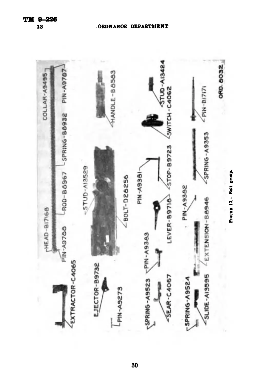
13. Disassembling.—a. Bolt group (fig. 18).—(1) Remove bolt
group from gun.
(2) Remove extractor by rotating upward and pulling out from
bolt The ejector and ejector spring can be removed after driving out
the ejector pin.
(8) Lift bolt switch off bolt switch stud.
(4) Rotate cocking lever fully backward and release firing pin by
pushing down the sear. Remove cocking lever pin and cocking lever.
(5) With thin end of cocking lever swing the sear stop out of its
groove in the bolt into the center of slot in the bolt; then turn bolt
over and push sear stop out of engagement with firing pin spring.
Reverse bolt and remove sear stop from slot.
(6) Depress sear and remove sear slide. Pull out sear and sear
spring.
(7) By holding the bolt with front end slightly elevated the firing
pin extension and firing pin will drop out. The firing pin spring can be
removed from the firing pin extension by driving out the firing pin
spring stop pin. Take precautions to prevent firing pin spring from
flying out during the operation. This should not be done unless it is
necessary to replace the firing pin spring.
(8) The driving spring and driving spring rod collar can be removed
from the driving spring rod assembly by driving out the driving
spring rod collar stop pin from the driving spring rod. This should
not be done unless it is necessary to replace the driving spring.
29
BOLT-026256
PIN A9362
ORDNANCE DEPARTMENT
5PRING-A9S24
5UDE-AI3595 EXTENSION - ВA946
- SPRING-A93S3
PIN-BI7I7I
ORO. 0032
Fiovil 13,—Belt froup.
ТМ 9-226
BROWNING MACHINE GUN, CAL. .50, М2, WATER-COOLED 13
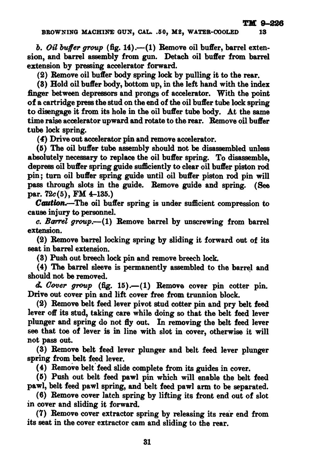
Ъ. Ой buffer group (fig. 14).—(1) Remove oil buffer, barrel exten-
sion, and barrel assembly from gun. Detach oil buffer from barrel
extension by pressing accelerator forward.
(2) Remove oil buffer body spring lock by pulling it to the rear.
(8) Hold oil buffer body, bottom up, in the left hand with the index
finger between depressors and prongs of accelerator. With the point
of a cartridge press the stud on the end of the oil buffer tube lock spring
to disengage it from its hole in the oil buffer tube body. At the same
time raise accelerator upward and rotate to the rear. Remove oil buffer
tube lock spring.
(4) Drive out accelerator pin and remove accelerator.
(5) The oil buffer tube assembly should not be disassembled unless
absolutely necessary to replace the oil buffer spring. To disassemble,
depress oil buffer spring guide sufficiently to clear oil buffer piston rod
pin; turn oil buffer spring guide until oil buffer piston rod pin will
pass through slots in the guide. Remove guide and spring. (See
par. 72c(5), FM 4-135.)
Caution.—The oil buffer spring is under sufficient compression to
cause injury to personnel.
c. Barrel group.—(1) Remove barrel by unscrewing from barrel
extension.
(2) Remove barrel locking spring by sliding it forward out of its
seat in barrel extension.
(8) Push out breech lock pin and remove breech lock.
(4) The barrel sleeve is permanently assembled to the barrel and
should not be removed.
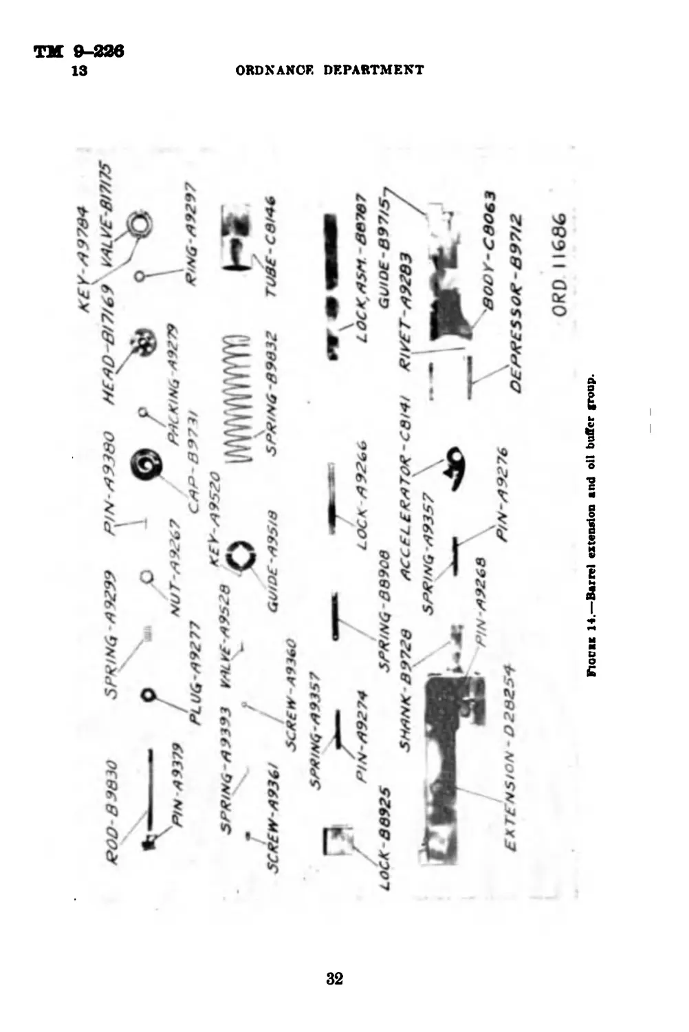
dl Cover group (fig. 15).—(1) Remove cover pin cotter pin.
Drive out cover pin and lift cover free from trunnion block.
(2) Remove belt feed lever pivot stud cotter pin and pry belt feed
lever off its stud, taking care while doing so that the belt feed lever
plunger and spring do not fly out. In removing the belt feed lever
see that toe of lever is in line with slot in cover, otherwise it will
not pass out.
(8) Remove belt feed lever plunger and belt feed lever plunger
spring from belt feed lever.
(4) Remove belt feed slide complete from its guides in cover.
(5) Push out belt feed pawl pin which will enable the belt feed
pawl, belt feed pawl spring, and belt feed pawl arm to be separated.
(6) Remove cover latch spring by lifting its front end out of slot
in cover and sliding it forward.
(7) Remove cover extractor spring by releasing its rear end from
its seat in the cover extractor cam and sliding to the rear.
81
ТМ 9-226
13
ORDNANCE DEPARTMENT
FioviK 14.—Barrel extension and oil buffer group.
32
TM 9-026
BROWNING MACHINE GUN, CAL. .60, М2, WATER-COOLED 13
LEVCP-C4057 / t-SPPING -0974/
^PINBFAXICE
273864 •—41----S
88
TM 9-226
13
ORDNANCE DEPARTMENT
(8) Withdraw cotter pin from end of cover latch shaft and remove
cover latch shaft assembly.
e. Back plate group (figs. 16 and 17).—(1) Drive out back plate
latch pin being careful that the back plate latch spring does not fly out
upon removal of back plate latch.
(2) Remove cotter pin, drive out latch lock pin, and remove latch
lock and latch lock spring.
(8) Drive out trigger pin being careful that the trigger spring
does not fly out upon removal of trigger and trigger spacer.
(4) Unscrew adjusting screw, remove adjusting screw plunger and
adjusting screw plunger spring.
(5) Remove buffer disks and buffer plate through the rear end
of the buffer tube.
/. Casing group (figs. 18 and 19).—(1) To prevent injury to rear
sight leaf, the rear sight movable base and rear sight leaf assembly
should be removed from the rear sight fixed base. Turn rear sight
windage screw knob until rack on movable base is entirely free from
windage screw, then lift assembly from movable base pivot. Lift off
movable base tension spring.
(2) To remove side plate trigger assembly from casing, withdraw
cotter pin from side plate trigger bolt and unscrew side plate trigger
nut To disassemble—
(a) Pull side plate trigger slide out of its guides in the side plate
trigger housing.
(&) Drive out side plate trigger pin and remove side plate trigger
cam and spring.
(8) To remove retracting slide* assembly from casing, pull out
locking wires and unscrew retracting slide bracket screws. The com-
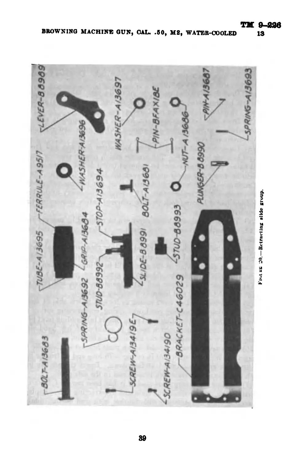
ponents of the retracting slide assembly are shown in figure 20. To
disassemble—
(a) Withdraw cotter pin from retracting slide bracket bolt.
Unscrew retracting slide nut and remove bolt from retracting slide
bracket
(&) Withdraw cotter pin from retracting slide lever stud. Un-
screw retracting slide nut and remove retracting slide lever stud
washer. Remove retracting slide lever and retracting slide grip
assembly from retracting slide lever stud. Remove retracting slide
lever spring.
(c) Remove retracting slide from retracting slide bracket
(rf) The retracting slide stud can be removed from the retracting
slide but this should not be done unless necessary for replacement
as the stud is staked in place.
84
TM 9-228
BROWNING MACHINE GUN, CAL. .60, М2, WATER-COOLED 13
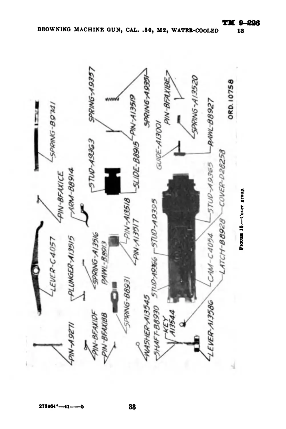
Fiooia 1в.—Back plate for nee on
В*Р-88944 \TQlGGEf?-B39ia vP/Ny49275 r-5R4CEf?-/4 L3533
85
ТМ 9-226
13
ORDNANCE DEPARTMENT
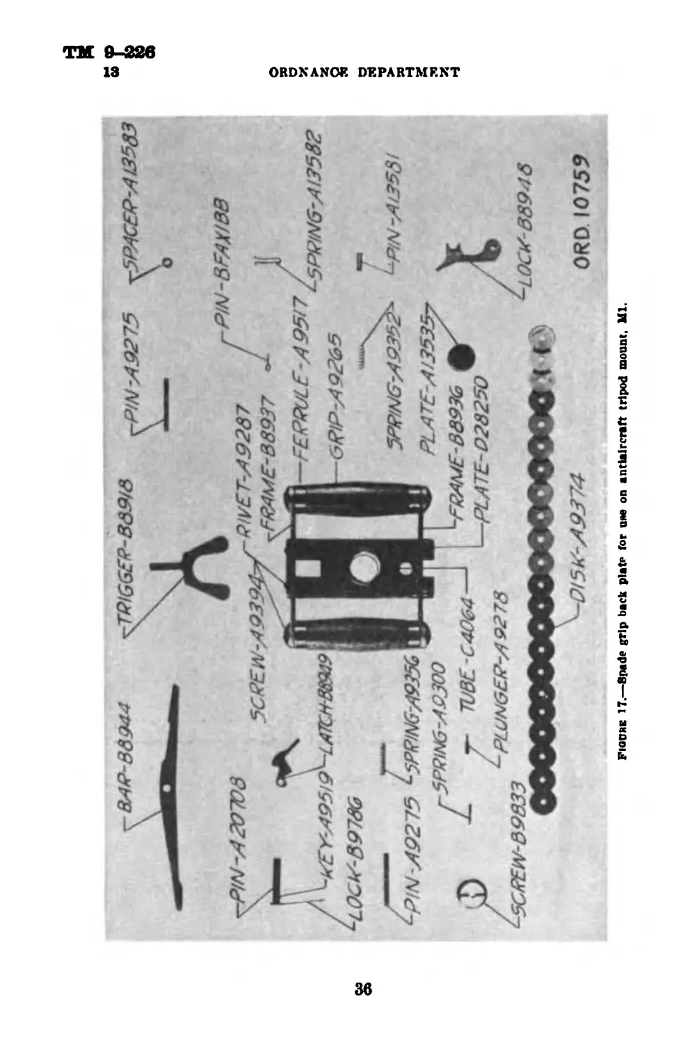
Figure 17.—Spade grip back plat? for use on antiaircraft tripod mount. Ш.
36
9-226
13
BROWNING MACHINS GUN, (ML. .60, MS, WATER-COOLED
ar
TM 9-826
18
ORDNANCE DEPARTMENT
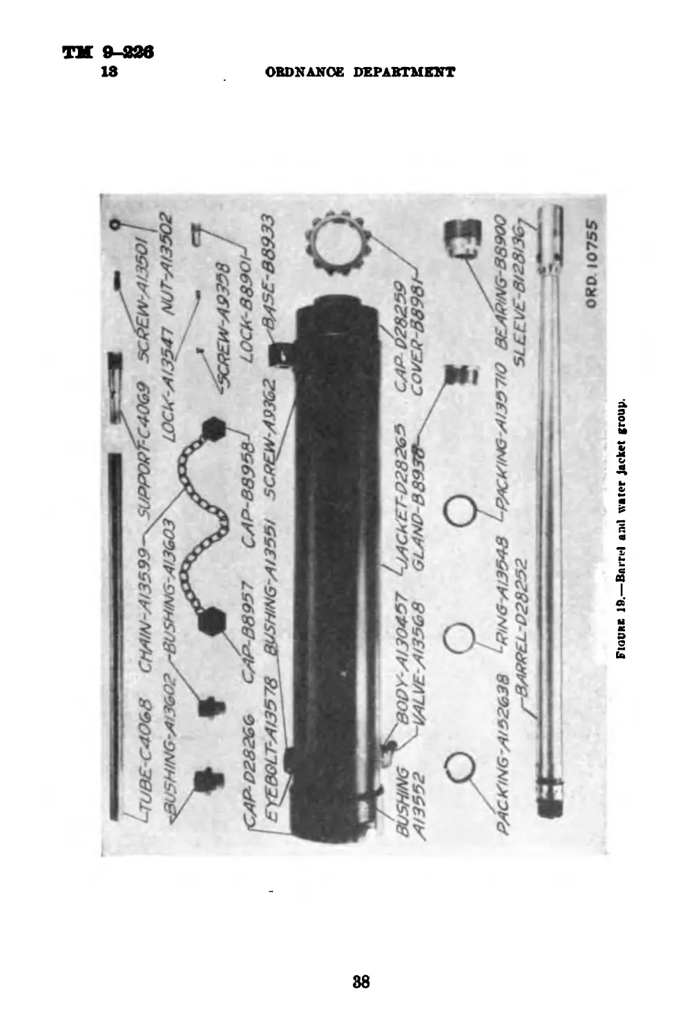
Figure 10.—Barrel ami water jacket group.
88
ТМ 9-236
BROWNING MACHINS GUN, OAL. .60, М2, WATER-COOLED 13
89
ТМ 9-226
13-14
ORDNANCE DEPARTMENT
(4) Lift end of trigger bar pin lock from its seat in the side
plate, rotate downward about 90° and pull out trigger bar pin*
Remove trigger bar.
(5) Remove cotter pin from switch pivot nut Unscrew nut and
remove switch and switch spring.
(6) Draw belt holding pawl pin out to the rear, taking care that
the belt holding pawl spring does not fly out upon removal of the
pawl. Remove belt holding pawl and spring.
(7) Draw belt holding pawl pin, located on the opposite side of
the feedway, out to the rear and remove link stripper and cartridge
stops, front and rear.
(8) Unscrew front barrel bearing lock screw jam nut and front
barrel bearing lock screw. The muzzle gland, muzzle packing ring,
and barrel packing may now be removed but it is not recommended
unless necessary for repair or to repack the barrel. (See par. IM.)
Caution.—The front barrel bearing must not be removed except
when necessary for replacement. If it becomes necessary to do this,
the front barrel bearing lock must be removed before unscrewing the
front barrel bearing.
(9) The front end cap thread cover can be removed by unscrewing.
14. Assembling.—a. Gating group.—(1) Replace front end cap
thread cover.
(2) If muzzle gland, muzzle gland packing ring, and barrel pack-
ing have been removed replace them and screw muzzle gland lightly
against ring and packing as the gland will be adjusted and locked in
place after the barrel is assembled to the gun. (See par. IM.)
(8) Position link stripper and cartridge stops, front and rear, on
right side of feedway and insert belt holding pawl pin.
(4) Place belt holding pawl spring in its seat in left side of feed-
way. Position belt holding pawl over spring, compressing spring to
allow insertion of belt holding pawl pin. Insert belt holding pawl pin.
(6) Place switch and switch spring in position on left hand side
plate. Screw on switch pivot nut and insert cotter pin.
(6) Place trigger bar in its slot in top plate bracket so that hole in
trigger bar is in line with hole in casing with long end of trigger bar
to the front and the cammed surface down. Insert trigger bar pin
with lock down and rotate lock into its seat in the side plate.
(7) Replace retracting slide stud if it has been removed from re-
tracting slide. Stake retracting slide stud to retracting slide. Replace
retracting slide in retracting slide bracket with stud on the slide to
the front Position retracting slide lever spring in its seat in re-
tracting slide lever with large loop of spring over the hole for the
40
ТМ 0-226
BROWNING MACHINE GUN, CAL. .50, М2, WATER-COOLED 14
retracting slide lever stud. Place retracting slide lever and spring on
retracting slide stud with small loop of spring over retracting slide
stop. Rotate retracting slide lever until it clears the stop. Depress
lever making certain the large loop of retracting slide lever spring
clears the collar of retracting slide lever stud. Replace retracting slide
lever stud washer and nut. Replace cotter pin in retracting slide lever
stud nut. Place retracting slide bracket bolt in its hole in retracting
slide bracket Screw on retracting slide bracket nut loosely.
(8) Place retracting slide assembly on right side of casing with holes
in the slide in line with holes in the side plate. Screw in retracting
slide bracket screws and replace locking wires. Tighten retracting
slide bracket nut and replace cotter pin.
(9) Seat side plate trigger spring in the side plate trigger housing.
Position side plate trigger cam over the spring and insert side plate
trigger pin. Insert side plate trigger slide in its guides in side plate
trigger housing and push the slide forward into position.
(10) Place side plate trigger assembly on left side of casing, inserting
the dovetailed end of housing into the forward slot in side plate. Ad-
just bolt to secure assembly to casing and tighten nut Insert cotter
pin in side plate trigger bolt.
(11) Place movable base tension spring over stud on rear sight
base. Place rear sight movable base and rear sight base assembly
over stud in rear sight base. Engage windage screw with rack of
movable base. Center sight by turning windage screw until sight
index mark on movable base is in line with zero mark on windage
scale.
b. Back plate group.—(1) Insert buffer plate and buffer disks in
buffer tube. Disks should be clean and free of rough edges and sur-
faces and should be assembled in the tube one at a time, being sure
that each disk is firmly seated.
(2) Replace adjusting screw plunger and spring in adjusting screw.
Insert adjusting screw in buffer tube and tighten.
(3) Replace trigger, trigger spacer, and trigger spring and insert
trigger pin.
(4) Replace latch lock spring and latch lock. Insert latch lock
pin and cotter pin.
(5) Replace back plate latch spring and back plate latch and
insert back plate latch pin.
<?. Caver group.—(1) Insert cover latch shaft assembly in hole
in cover and replace cotter pin.
(2) Place forked end of cover extractor spring over stud in cover
and engage the other end of spring in slot in cover extractor cam.
273864*—41---6
41
ТМ 9-226
14
OBDNANOE DEPARTMENT
(8) Place cover latch spring over stud in cover and slide forward,
making certain that the rear end rests on the cover latch.
(4) Hold belt feed pawl with recess for belt feed pawl spring up
and studs to the right Place belt feed arm over studs on belt feed pawl
with belt feed arm pointing to the right and holes in belt feed pawl
and arm in alinement Place belt feed pawl spring in its seat in
pawl and position belt feed pawl in* belt feed slide. Insert belt feed
pawl pin. Insert belt feed slide, complete, in its guides in the cover
making certain that belt feed pawl arm is to the rear.
(5) Place belt feed lever plunger and spring in rear hole of belt feed
lever. Insert toe of belt feed lever through slot in cover and engaging
belt feed slide» Position belt feed lever so that it goes over stud in
cover, and at the same time compress belt feed lever plunger and spring
so that they clear the side of the cover. Insert cotter pin in stud.
(6) Place cover assembly on trunnion block and insert cover pin.
Insert cotter pin in cover pin.
d. Barrel group.—(1) Insert breech lock in its guides in barrel ex-
tension making certain that bevel faces of breech lock are to the front
with the double bevel on the top. Insert breech lock pin, taking care
that both ends of pin are flush with sides of barrel extension.
(2) Replace barrel locking spring by sliding it into its seat in barrel
extension.
(8) Screw barrel into barrel extension.
e. Ой buffer group.—(1) Assembling.—(a) If the oil buffer tube
has been disassembled, place oil buffer spring over oil buffer piston rod.
Position oil buffer spring guide so that slot in guide is in line with pin
on oil buffer piston rod. Press down on oil buffer piston guide so that
oil buffer piston rod pin passes through slot in guide and rotate guide
until recesses in the guide are alined with the pin in the rod. Allow
pin to seat itself in recesses.
(&) Insert oil buffer body spring lock in its groove in the body and
push forward.
(<?) Position oil buffer tube lock spring over slot in oil buffer body
with flanges of the spring over the enlarged cut in the slot. Depress
spring into the cut and slide forward, raising stud end of spring up
and over the end of oil buffer to seat stud in hole in oil buffer body.
(d) Insert oil buffer tube assembly in oil buffer body and push
forward as far as it will go. Place accelerator, with tips up and the
rounded surface to the front, between depressors on oil buffer body
and insert accelerator pin, taking care that both ends of pin are
flush with the sides of oil buffer body.
42
TM 0-226
BROWNING MACHINE GUN, OAL. .50, М2, WATBR-OOOLED 14
(2) Adjustment of oil buffer.—(a) The oil buffer is so arranged
that it is possible to adjust the speed of the firing of the machine
gun. This is accomplished by turning the oil buffer tube the required
number of clicks, depending on whether a high rate of fire is desired
or a slower rate.
(b) Turning the buffer tube to the right tends to cut off or close
the oil buffer which allows it to absorb more recoil and to reduce the
rate of fire.
(c) Turning the buffer tube to the left allows the oil buffer to open
and allows the oil to pass through larger throttling ports which results
in an increased rate of fire.
(d) The oil buffer tube is turned by inserting a screw driver
blade into the slot in the rear of the buffer tube through the hole
in the back plate.
f. Bolt group.—(1) Assemble firing pin and firing pin extension
and insert this assembly into firing pin hole in bolt with the notch
of firing pin extension down. Push forward until striker projects
through small hole in front of bolt.
(2) Seat sear spring in its recess in bolt. Insert sear in its guides
in bolt. Press down on sear enough to allow sear slide to be inserted
from left side of bolt In inserting sear slide the bevel end should
be inserted first and the V-cut in the sear slide should be on the
bottom. When the cut on the sear slide is over the corresponding
cam on the sear, release pressure on sear and the slide will be engaged.
(3) Insert pin of sear stop through firing pin extension and depress
sear stop as far as it will go. With thin end of cocking lever, swing
the spring end of sear stop into its recess in bolt
(4) Insert cocking lever in bolt, the rounded nose on lower end of
cocking lever to rear of the bolt so that it will properly engage the rear
of slot in firing pin extension. Line up the hole in cocking lever with
the holes in bolt and insert cocking lever pin from the left side.
(5) Cock by pressing forward on cocking lever. Turn cocking lever
to the rear and press in on sear slide to release firing pin and test
correctness of the assembly.
(6) Place bolt switch over bolt switch stud with enlarged portion of
bolt switch to the front of bolt.
(7) If the ejector and ejector, spring have been removed, replace
them on the extractor and insert ejector pin. Holding extractor in an
upright position insert stud of extractor into the hole in the bolt and
rotate downward being sure that the flange on the extractor is under
the collar on the bolt.
48
ТМ 9-226
14-10 ORDNANCE DEPARTMENT
(8) If driving spring rod has been disassembled, place driving
spring over driving spring rod and compress the spring enough to
allow the driving spring rod collar to fall below the hole for the driving
spring rod collar stop pin. Insert pin and peen the end of pin to
prevent loss.
15. Packing barrel.—Remove barrel assembly from gun.
л To pack breechend.—Unscrew packing adjusting ring and remove
old rear barrel packing. Clean recess in barrel and insert new rear
barrel packing. Smooth barrel packing until ends meet Screw pack-
ing adjusting ring against barrel packing to hold it in place.
b. To pack muzzle end.—Unscrew front barrel bearing lock screw
jam nut and front barrel bearing lock screw. Unscrew and remove
muzzle gland. Remove muzzle packing ring and old front barrel pack-
ing. Clean out inside of front barrel bearing. Insert new front bar-
rel packing and replace muzzle packing ring and muzzle gland. Screw
muzzle gland lightly against ring and packing as the gland will be
adjusted and locked in place after the barrel is reassembled in the gun.'
c. Reassemble barrel assembly into gun being careful not to injure
barrel packing.
d. Adjust front barrel packing (muzzle packing) by tightening or
loosening muzzle gland, then lock in place with front barrel bearing
lock screw and jam nut
e. Adjust rear barrel packing (breach packing) by tightening or
loosening packing adjusting ring. A packing ring adjusting wrench
and a barrel holding wrench are provided for this purpose.
16. Changing barrels.—a. Open drain valve and drain water
from water jacket into water chest or other suitable receptacle. Re-
move back plate, bolt, and driving spring assemblies. Remove barrel,
barrel extension, and oil buffer assembly by pulling out to the rear.
Separate old barrel from barrel extension and replace with new one.
Reassemble barrel, barrel extension, oil buffer, bolt, driving spring,
and back plate assemblies to the gun. Care must be exercised in re-
moving and assembling the barrel in order not to disarrange the barrel
packing. Make head space adjustment as outlined in paragraph 12.
Close drain valve and refill water jacket with water. Adjust breech
and muzzle barrel packing if necessary.
b. If it is necessary to keep water in water jacket when changing
barrels the following method can be employed: Remove back plate,
bolt, and driving spring assemblies. Screw union caps to inlet and
outlet openings of water jacket and lower muzzle of gun to prevent
loss of water at the breech end. Hold a plug at muzzle of barrel.
Withdraw oil buffer, barrel extension, and barrel assemblies to the
44
ТМ 9-006
BROWNING MACHINS GUN, (ML. .60, М2, WATER-COOLED 16-17
rear. As the barrel is withdrawn, follow it with the plug and insert
plug in hole in muzzle gland through which the barrel has been with-
drawn. Place a plug or twisted patch in muzzle of new barrel. Sep-
arate old barrel from barrel extension and replace with new one. Re-
assemble barrel, barrel extension, and oil buffer assemblies into gun.
When the muzzle of the new barrel passes through hole in muzzle gland
remove plug in the hole. Remove plug in muzzle of barrel and run a
cleaning patch through barrel. Reassemble bolt, driving spring, and
back plate assemblies into gun. Make head space adjustment as out-
lined in paragraph 12. Adjust breech and muzzle barrel packing if
necessary.
Section 1П
DISMOUNTING AND MOUNTING
Paragraph
Dismounting antiaircraft machine-gun mount, caliber .50, М2____________________ 17
Mounting antiaircraft machine-gun mount, caliber Л0, М2,_______________________IS
Dismounting antiaircraft machine-gun tripod mount, Ml-------------------------- 19
Mounting antiaircraft machine-gun tripod mount, Ml_____________________________ 20
17. Dismounting antiaircraft machine-gun mount, caliber
.50, M0 (fig. 21).—a. Disconnect flexible cables at front sight mecha-
nism. Remove ammunition chest and disconnect eyebolt (if in use)
by unscrewing the hook.
Ъ. Dismounting sights.—Rotate front sight 90° to clear the under-
cut, and remove front sight Unlatch clamp of sight support and
remove rear sight from rear sight bracket. Loosen lock nut on rear
sight clamp, unscrew knob and slide rear sight bracket out of dovetail
clamp. Unscrew the two knobs on sight support, pull back on front
sight locking plate so that the large openings in the plate can dear
the clamping bolts of the sight support. Remove front sight locking
plate by unscrewing retaining screw. Raise front sight mechanism
out of its dovetail in sight support.
c. Dismounting gun.—Before removing the caliber .50 machine gun
from the cradle of the М2 mount, force gun slightly to rear and push
down lower recoil slide stop which is located on the right of lower
recoil slide. This will prevent the recoil slide from going too far
forward when the gun is removed. If this is not done, difficulty will
be encountered in properly alining the slide and the gun bracket to
insert the rear gun joint pin when mounting the gun. This stop will
return automatically to the disengaged position after the first round
is fired. Release trunnion cap wing nuts and raise trunnion caps.
Pull out rear gun joint pin and lift gun out of cradle. In removing
the gun, do not allow side plate trigger to come in contact with cradle
as such contact may injure the trigger mechanism.
45
ORDNANCE DEPARTMENT
ORD. 13284
Fiouac 21.—Antiaircraft machine-gun
mount. caliber ЛО. М2, component* and machine gun.
ТМ 9-226
BROWNING MACHINE GUN, CAL. .50, М2, WATER-COOLED 17-19
d. Diemounting cradle and pintle.—Release pintle lock on pedestal
by placing lever of lock in a horizontal position. Lift cradle and pintle
from pedestal.
e. Diemounting tripod lege.—Unscrew leg clamping ring. Release
nuts on the bolts which fasten the tripod legs to the base ring by screw-
ing the nuts out against the stops. Remove tripod legs by sliding them
downward out of slots in base ring. In removing the legs, the pedestal
is tilted so that the leg being removed is clear of the ground.
18. Mounting antiaircraft machine-gun mount, caliber .50,
М2.—a. Slide legs into slots in base ring and tighten nuts. Tighten
leg clamping ring.
b. Raise latch lock lever to horizontal position and place cradle and
pintle on pedestal. Latch pintle latch lock.
c. Raise trunnion caps. Place machine gun on cradle with gun trun-
nions seated in trunnion slides. Lower the rear end of gun over the
bracket of the lower recoil slide until holes in gun bracket are alined
with holes in slide of recoil mechanism. Insert rear gun joint pin
through gun bracket and slide of recoil mechanism.
d. Slide rear sight bracket into dovetail of rear sight clamp.
Tighten clamp with the knob and lock in place with the locking nut.
Place rear sight in groove in rear sight bracket making sure that the
cut on the flange of the rear sight engages the pin in rear sight bracket.
Latch rear sight bracket.
e. Place front sight mechanism in its dovetail in sight support. Place
front side locking plate over heads of clamping bolts with chamfered
side of slots upward. Slide plate forward so that heads of clamping
bolts enter narrow portion of slots. Insert and tighten plate retaining
screw. Clamp sight mechanism to sight support by tightening clamp-
ing knobs. Place front sight with the flat at right angles to the flat
on elevating screw head and rotate sight 90° in undercut until the
spring actuated plunger in the elevating screw head engages the mat-
ing detent in the sight.
/. Connect flexible cables to elevating and traversing mechanisms on
front sight assembly.
19. Dismounting antiaircraft machine-gun tripod mount,
Ml.—a. Withdraw trunnion pin and elevating bracket pin and re-
move gun.
b. Pull out on locking plunger and remove cradle and yoke.
o. Unscrew shoulder stock assembly from front bracket of cradle.
d. Unscrew locking collar from end of shoulder stock assembly, then
pull shoulder stock assembly out of rear bracket of cradle.
47
ТМ 9-226
90-21
ORDNANCE DEPARTMENT
20. Mounting antiaircraft machine-gun tripod mount»
Ml—a. Insert shoulder stock assembly into rear bracket of cradle
and screw locking collar on end of shoulder stock assembly.
b. Screw shoulder stock assembly on front bracket of cradle.
c. Replace cradle and yoke and engage locking plunger.
d. Place gun over cradle so that trunnion pin hole is directly over
the caliber .30 trunnion pin hole in rear of cradle, and lower gun and
move forward until trunnion pin and elevating bracket pin holes are
in line with corresponding holes in cradle. This is necessary as the
projecting trunnion block rivets of the caliber .50 gun interfere
with the bosses for the caliber .30 trunnion pin holes. Insert ele-
vating bracket pin and trunnion pin.
Section IV
STOPPAGES AND IMMEDIATE ACTION
Paragraph
Stoppages___________________________________________________________ 21
Immediate action____________________________________________________ 22
21. Stoppages.—General.—a. A malfunction is an improper ac-
tion of some part of the gun, resulting in a stoppage; for example,
failure to extract the empty cartridge case.
b. Any accidental cessation of fire is a stoppage. It may be a
faulty cartridge or a malfunction of some part of the gun.
a Immediate action is the term applied to that operation required
to clear a temporary stoppage.
d. Proper care of the gun and attention to the points before, dur-
ing, and after firing will greatly reduce the liability to stoppages,
particularly if the gunner has an intelligent understanding of the
reason why stoppages generally occur. Prevention is the beet rem-
edy for dtl stoppages.
Caution.—After any stoppage which appears to be caused by in-
sufficient recoil, make sure that the bore is clear before continuing
firing. It is possible that such a stoppage, for instance, one caused
by incomplete ignition of the powder charge, may result in the bullet
lodging in the bore, and in case this happens and another round is
fired before the bore is cleared, the gun certainly will be seriously
damaged.
e. Classes.—Stoppages may be classed under two main headings:
(1) Temporary.—Temporary stoppages are caused by—
(a) Failure of some part, duplicate of which is carried with the
gun.
(b) Faulty ammunition.
(a) Neglect of points before or during firing.
48
TM 9-22в
BROWNING MACHINE GUN, OAL. .50, М2, WATER-COOLED 21
(2) Prolonged.—Prolonged stoppages are caused by a failure of
some part that, as a rule, cannot be remedied by the gun squad under
fire or without skilled assistance. These necessarily put the gun out
of action for a more or less prolonged period.
/. Unusual malfunctions.—(1) Recurring short rounds.—Excessive
wear of the parts of the feed mechanism may cause recurring short
rounds. Inspection of the base of the first cartridge removed from
the belt will show a dent in the rear end of the case made by the
comer of the extractor. This stoppage is remedied by inspecting
feed mechanism and replacing defective parts. Inspection of am-
munition belts before firing will disclose short rounds inherent in
the ammunition.
(2) Loose bullets.—In some lots of ammunition which have de-
teriorated from storage or exposure, the front end of the case is not
securely crimped on the bullet. When the extractor withdraws the
cartridge from the belt the case only is withdrawn, leaving the bullet
in the belt. Loose powder scattered in the mechanism may cause
a stoppage. This stoppage is remedied by removing the obstruction.
The best prevention of this type of stoppage is a rigid inspection of
ammunition prior to firing.
(3) Broken У •slot.—A broken T-slot will fail to extract the empty
case from the chamber and will usually scar the rim of the case. This
stoppage is remedied by replacing the bolt
(4) Broken barrel extension.—The bolt will not go home and the
gun will generally stop firing. In rare cases the gun will fire a few
rounds with a broken barrel extension. This stoppage is remedied
by disassembling the gun and replacing the broken part.
(5) Uncontrolled automatic fire.—Uncontrolled automatic fire is
the continuation of fire when the trigger or sear mechanism is re-
leased. If the cause is present before the gun is fired it will com-
mence the moment the bolt is home the second time during loading;
or if the defect occurs during firing, the gun will not stop firing when
the trigger or sear mechanism is released.
(a) Cause.—The forward end of the trigger bar sprung downward,
or the beveled surfaces of the trigger bar and sear burred.
(b) To remedy.
1. Keep gun directed on target
8. Unlatch cover.
3. Unload and disassemble gun. Replace broken, worn, or
burred parts.
(6) Tight packing.—Too tight packing will, result in sluggish
operation and stoppages. Muzzle packing is more likely to cause
trouble than breech packing.
49
IM 9-226
21
ORDNANCE DEPARTMENT
(7) Cla8wfie& table of stoppages.—The following table will serve
as a guide during instruction in stoppages or immediate action:
TABLE OF STOPPAGES
Stoppages
Method of preparation for instruction in immediate
action and stoppages
1. Misfire due to defective primer.
2. Short round.
3. Bulged round.
4. Tight link in the belt.1
5. Thin rim, permitting the nose of
the bullet to drop below cham-
ber.1
6. Belt improperly loaded.
7. Battered or thick rim of cartridge.
8. Failure to remove round from
chamber.
9. Set-back primer.1
10. Separated case which is removed
from chamber by new round
when bolt is pulled to rear.
11. Separated case, which stays in the
chamber when bolt is pulled up
to rear. (Do not set up loose
head space.)
12. Bullet loose in cartridge case. Car-
tridge case extracted from belt
but bullet remains in belt.1
13. Short or broken firing pin.
14. Weak or broken firing pin spring.
15. Faulty engagement of firing pin
ana sear notch.
16. Broken sear spring.
17. Bent or worn belt feed lever.
18. Belt feed pawl spring out or weak.
19. Belt feed pawl pin out or partially
out.
20. Cover extractor spring out or weak.
21. Belt feed lever bent up (stud on
lever jumps out of cam groove).
Damaged extractor.
Belt-holding pawl out or spring
weak.
Broken extractor or ejector.
Broken or damaged T-slot in bolt.1
Weak ejector spring.
Broken barrel extension.
Defective trigger mechanism.19
Defective bolt switch.1
Bent or broken belt feed pawl arm.1
1. Place dummy cartridge in belt.
2. Place short round in belt.
8. Insert bulged round in belt.
4. Do not prepare.1
5. Do not prepare.1
6. Pull cartridge partially out of belt.
7. Place battered or thick-rimmed car-
tridge in belt.
8. Place dummy cartridge with rim
filed off in chamber.
9. Do not prepare.1
10. Drive front portion of a cartridge
securely on a dummy cartridge.
Pull bolt to rear and place car-
tridge properly on face of bolt.
Ease bolt forward.
11. Insert front end of a separated case
in chamber, and load.
12. Do not prepare.1
13. Place five or six successive range
dummy cartridges in belt for in-
struction in immediate action.
14. Same as 13.
15. Same as 13.
16. Same as 18.
17. Assemble cover with defective part.
18. Remove belt feed pawl spring.
19. Remove belt feed pawl pm.
20. Remove cover extractor spring.
21. Assemble with defective part.
22. Same as 21.
23. Remove belt-holding pawl.
24. Assemble bolt with defective part.
25. Do not prepare.1
26. Assemble with defective part.
27. Assemble with defective part.
28. Do not prepare.1 ’
29. Do not prepare.1
30. Do not prepare.1
1 Not prepared for instruction in immediate action.
’ Defective trigger mechanism may cause the gun to begin firing as soon as it
is loaded or to continue to fire when the trigger is released. To remedy, unlatch
the cover or twist the belt, unload, disassemble the gun, and replace the defective
part or parts.
50
ТМ 9-226
BROWNING MACHINE GUN, CAL. .50, М2, WATER-COOLED 88
22. Immediate action.—a. Immediate action is the immediate
and automatic application of a procedure designed to reduce the ma-
jority of stoppages and place the gun in action in the shortest possible
time. Immediate action is concerned with the reduction of stoppages
and not the cause.
b. Proper preparation of the gun and inspection of the loaded belts
to eliminate loose bullets, bulged round etc., should practically elimi-
nate the need of immediate action.
<?. When a stoppage occurs during firing, the immediate action in
the diagram below, or such portions as are required to reduce the stop-
page will be performed.
TABLE OF IMMEDIATE ACTION
Gun falls to fire
I
Pull the bolt to the rear, release it and attempt to fire
I
If the gun still falls to fire
I
See If cover is latched, straighten ammunition belt, place hand to feel rounds
entering feedway, and pull the bolt to the rear and release It.
If belt feeds If the belt does not feed
I I
Attempt to fire Raise the corer, remove the first
I round from the belt and look or feel
И gun still fall, to Are for a cartridge In the gun.
Change bolt If a cartridge is
I ! 1
In the gun NOT In the gun
I I
Remove It Reload, re-lay, and fire
Reload, re-lay, and fire
Note.—If application of the procedure does not remedy the stoppage, the
gunner must examine the feed mechanism and other parts of the gun in order
to locate and remedy the trouble.
51
TM 9-226
83-85 ORDNANCE DEPARTMENT
Section V
CARE AND PRESERVATION
Paragraph
Genera]---------------------------------------------------------------- 23
Points to be observed before, during; and after firing----------------- 24
Care and cleaning of gun_______________________________________________ 25
Method of fining oil buffer-------------------------------------------- 26
Precautions to be observed during cold weather------------------------- 27
Precautions to be observed during gas attack--------------------------- 28
23. General.—The importance of a thorough knowledge of how
to care for and clean the machine gun cannot be overemphasized. The
kind of attention given to a weapon of this type determines largely
whether or not it will shoot accurately and function properly when
needed. The bore and chamber must be kept in* perfect condition
for accurate shooting. Also it is just as important that the receiver
and moving parts be kept clean, lubricated, and in perfect condition
for efficient functioning.
24. Points to be observed before, during, and after firing.—
The following table of points to be observed before, during, and after
firing will be found convenient as a guide for the proper care of the
gun at all times. It will also serve as a guide for the inspection of
the gun.
25. Care and cleaning of gun.—a. (Hearting bore.—(1) Disas-
semble groups from gun.
(2) Place barrel, muzzle down, in a vessel containing hot water and
issue soap, a sal soda solution, or, lacking these, hot water alone.
(3) Insert cleaning rod with a flannel patch assembled in the breech.
Move rod forward and back for about 1 minute, pumping water in
and out of bore.
(4) Use a brass or bronze wire brush while the bore is wet, run-
ning it forward and back through the barrel three or four times.
(5) Pump water through bore again to clean.
(6) Dry the cleaning rod and remove barrel from water. Using
dry, clean flannel patches, thoroughly swab bore until it is perfectly
dry and dean. Thoroughly dry and dean the chamber using a flannel
patch on a stick if necessary.
(7) Saturate a patch with sperm oil and swab bore and chamber
with the patch. Allow a thin coat of the oil to remain in the bore.
(8) Guns diould be cleaned not later than the evening of the day
on which the gun is fired, preferably immediately after cessation of
firing.
(9) Inspect and dean the guns for 8 days following cessation of
firing.
52
ТМ 2-226
BROWNING MACHINE GUN, CAL. .50, М2, WATEE-OOOLED 25
b. Cleaawng part» other than bore,—(1) Wipe receiver clean, care
being taken to remove dirt from belt holding pawh Thoroughly clean
cover, bolt, barrel extension, oil buffer, and back plate, using a small
stick covered with a flannel patch to remove dirt from all recesses.
(2) Wipe all parts with an oily rag.
(8) The gun should be examined to see if the barrel packing is in
good condition.
a (Jlewwng tripod.—(1) The tripod should be given care equal to
that given the gun. All parts which are painted when issued will be
kept at all times properly protected by olive-drab paint Whenever
the tripod is used, all dirt, sand, and mud will be removed by wiping
or if necessary by washing and drying. Keep all threads lightly oiled.
(2) For the antiaircraft machine gun mount, caliber .50, М2, use
Navy contract #2110 lubricating oil. Lubricate the slide of the recoil
mechanism through the oil hole located in the top of the slide. The
slide should be lubricated every 2 hours during continuous firing. The
elevating and traversing screw should be oiled with a few drops of
oil every day.
d. Preparation for storage.—(1) Clean and prepare the guns with
particular care. All parts of the gun should be cleaned and wiped
thoroughly dry with rags. In damp climates particular care must be
taken to see that the rags are dry. After drying, the bare hands should
not touch the parts; handle with an oily rag.
(2) Apply rust-preventive compound to all metal parts of the gun.
Rust-preventive compound, medium (U. S. A. Spec. 2-84A), is a slug-
gish liquid which pours at a temperature of 81° F. It is used for short
time protection and should not be used on guns put in permanent
storage. It may be applied with a brush or by dipping. In applying,
heating is not necessary except in very cold temperatures. Applica-
tion of the rust-preventive compound to the bore of the machine gun
barrel is done best by dipping the cleaning brush in rust-preventive
compound and running it through the bore two or three times. Prior
to placing the weapon in storage the bolt should be in the forward
position with the firing pin released. In fact it is good practice to re-
lieve the firing pin tension whenever the weapon is not in use.
(3) The wooden supports in the packing box must be painted with
rust-preventive compound before storing the gun. Place the gun in
the wooden packing box, handling the gun with oiled rags.
e. &uns received from storage.—Machine guns received from storage
are completely coated with rust-preventive compound. Use dry-clean-
ing solvent to remove all traces of this grease, particular care being
taken that all recesses in which springs or plungers operate are cleaned
58
Pointe to be observed before, during, and after firing
Before Duriof Durtn< temporary сммПоп After
Bore Look through and dean Clean bore Clean and oil.
Muxzle gland. Pack and tighten. (See par. 15d.) Oil and test for worn or Examine and tighten Examine and repack if re- quired. Remove bolt, oQ buffer, barrel extension, and bar- rel; clean, oil, replace, and release firing pin. Adjust correctly and test. Examine band locking spring. Examine and replace if
Moving parts Keep oiled if required. Inspect and oil; dean dirt from bdt hold- ing pawL
Head space broken parts. See that parts function without ex- cessive friction. Make correct adjustment and test. (Sec par. 12.) Ex- amine barrel locking spring. Examine for leakage or ex- cessive friction. Clean and free from grease, See that sight is In good mechanical condition. Set sight at 700, wind gage at Tighten if several sepa- rated cases occur. Watch for leakage
Packing Examine for leakage Keep properly set
Rear sight and wind саке. X Keep properly set necessary. Clean and oil. Set sight at 700 and wind gage at 0.
Tripod Set tripod firmly, with no lost motion; legs, clamps, and clamping handle tight and with dial and traversing stops in proper condition. Fill water jacket, see that water plugs ana hose con- nections are tight and that there is a sufficient supply of water.1 See that belts are clean and se- cure sufficient supply of ammunition. Inspect am- munition. See that the oilcan is full. Keep firmly set with all damps properly ad- justed. Keep water jacket full and plugs and hose connections tight. Keep belt in line with feed opening. Examine. ....... Clean and oil.
Water - Keep water jacket full and plugs and hose connections tight. Replace belt with full one if necessary. Refill oilcan Empty all water into box. Wash out or flush water jacket if muddy or dirty water has been used. Clean and refill all belts. Separate live rounds from empty cases. Inspect am- munition. Refill oilcan.
Belta and ammunition.. OU
Spare parte and tools... Gun record Keep clean and oiled. See that kite are complete. Check from last firing to see that repairs have been made. For overhead fire see that 5,000 rounds per barrel have not been exceeded. Keep within reach Make repairs. Replace broken or worn parts. Note performance on gun report. Check, replace broken or missing parts, dean, and oil. Complete gun record.
1 If the gun is fired without circulating unit the outlet hole in the water jacket must be left uncovered.
8
TM 9-226
26 ORDNANCE DEPARTMENT
thoroughly. After using the dry-cleaning solvent make sure it is com-
pletely removed from all parts by wiping thoroughly. The bore and
chamber of tjie barrel must be thoroughly cleaned. All surfaces having
been thoroughly cleaned they should then be protected with a thin
film of lubricating oil applied with a rag.
Nobsl—Failure to dean the firing pin and driving spring and the recesses in the
bolt in which they operate may result in gun failure at normal temperatures, and
win most certainly result in serious malfunctions if the guns are operated in low
temperature areas as rust-preventive compound and other foreign matter will
cause the lubricating oil to congeal or frost on the mechanism.
f. Dry-cleaning solvent (Fed. Spec. P-S-661a).—This is a noncor-
rosive petroleum distillate of low inflammability, used for removing
grease. It is generally applied with rag swabs to large parts and as a
bath for small parts. The surfaces must be thoroughly dried imme-
diately after removal of the solvent To avoid leaving finger marks,
which are ordinarily acid and induce corrosion, gloves should be worn
by persons handling parts after such cleaning. Dry-cleaning solvent
will attack and discolor rubber.
g. Lubricating ail.—(1) Proper oiling is second in importance only
to intelligent cleaning. It is a vital necessity for the working parts
but should be used sparingly. Oil all bearing surfaces of the gun
before firing, taking particular care to see that the exterior of the
barrel is oiled at the breech end, also that the cover extractor spring,
the cover extractor cam, and the cover detent pawl are oiled. Oil the
cocking lever, the groove in the bolt for the belt feed lever, the grooves
in the barrel extension to take the bolt ribs, the breech lock cam, the
switch, the extractor cam, the sear mechanism, and the ways of the
belt feed slide.
(2) If the gun is to be fired in areas where the temperature is 45° F.
or above, sperm oil should be used when available. When not available,
motor oil, weight 20, or any light grade machine oil may be used in an
emergency.
(8) On all types of machine guns when operated in areas where the
temperature is below 45° F., aircraft instrument and machine-gun
lubricating oil (U. S. A. Spec. 2-27D) should be used.
(4) For lubricating the М2 mount, sperm oil (U. S. A. Spec. 2-45A)
or aircraft instrument and machine-gun lubricating oil (U. S. A. Spec.
2-27D) should be used under the same conditions as in the case of the
gun. If either of these is not available, any suitable motor oil or
machine oil may be used.
66
ТМ 9-226
BROWNING MACHINE GUN, GAL. .50, М2, WATER-COOLED 26-88
26. Method of filling oil buffer.—Remove the oil buffer tube
filling screws from the base of the buffer tube. Use the oil buffer filling
oiler filled with machine gun recoil oil (U. S. A. Spec. 2-77). In an
emergency any light recoil oil may be used, adding glycerin in freezing
temperatures if necessary. Start the flow of oil by pressing on the base
of the oiler. While the oil. continues to pour from the oiler, insert
nozzle into either filling hole and with a continued pressure on the
base of the oiler allow oil to flow into the buffer tube. Do not release
pressure on oiler until nozzle has been removed from fitting hole, thus
avoiding getting air bubbles into the buffer tube. Repeat the opera-
tion until the buffer is overflowing. Replace the filling screws. Any
excess oil in the buffer will be relieved by the relief valve in the forward
end of the buffer body. The reason that two filling holes are provided
is to show visually by overflow when the buffer tube is completely full.
27. Precautions to be observed during cold weather.—a. See
that the water in the cooling system does not freeze. In locations where
the atmospheric temperature is frequently below 82° F., it is necessary
to have an antifreeze mixture of some kind available that can be used
in the water jacket that will not freeze nor gum and yet will cool the
barrel. Engine crank case oil drainings are excellent for this purpose
and their use is authorized. It must be remembered that this mixture
cannot be used satisfactorily where the atmospheric temperature is in
excess of 82° F. No circulating unit or steam condensing device is
necessary when oil drainings are used in the water jacket but the outlet
hole must be uncovered before the gun is fired.
b. Test the gun frequently to see that it functions properly.
c. During cold weather when the gun is silent, the movable parts in
the receiver of the gun must be kept absolutely dry and free from oil
but before firing the gun the moving parts should be oiled.
28. Precautions to be observed during gas attack.—a. Cover
guns with waterproof sheet if available.
b. Work recoiling parts if the gun is not being fired.
o. Guns should be cleaned as soon as possible after a gas attack.
d. Oiling will prevent corrosion for about 12 hours.
e. Clean all metal parts in boiling water containing a little soda.
/. All traces of gas must be removed from ammunition with a
slightly oiled rag, then thoroughly dry the ammunition.
g. Rust-preventive compound resists gas corrosion more than
lighter oil.
67
TM 9-228
29 ORDNANCE DEPARTMENT
Section VI
SIGHTING AND FIRE CONTROL EQUIPMENT
Paragraph
Control equipment set, automatic gun, antiaircraft, Ml______ 29
Finder, range, 1-meter base, М191в------------------------- 80
29. Control equipment set, automatic gun, antiaircraft,
Ml.—One automatic gun antiaircraft control equipment set, Ml (figs.
22 and 23) is furnished for each firing unit of four Browning machine
guns, caliber .60, М2, water-cooled. The set complete consists of the
control box, twenty 50-foot flexible shafts including two spares, and
the necessary packing chests for control box and flexible shafts.
a. Description.—The control equipment set is a manually operated
mechanical data transmission system, used to transmit corrected de-
flection data to the sighting systems of the guns. Vertical and lateral
deflections, determined by a computing device if available, not a part
of the set, are transmitted by flexible input shafts to the control box
of the set. If the computing device is not available, the deflections
are set in manually by the. officers directing the fire. This control
box (fig. 24), which is not a computing device, contains differential
drives whereby corrections may be added to the values received, and
follow-the-pointer mechanisms, driven by handwheels, whence the
corrected data are transmitted by the flexible output shafts to the
sights of the guns.
ft. Operation.—(1) Set up the control box. Carry the control box
in its packing chest to the desired location which should be on firm,
level ground. Release the four trunk bolts and remove the lid of the
packing chest. Grasp the control box by the base and lift it from the
chest Remove the operator seat locking pins holding the folding seat
supports to the bottom of the chest Unfold the seats upward and
outward until the seats are substantially level and the holes in the
projecting legs of the horizontal seat supporting bars are alined with
the holes in the blocks at the ends of the packing chest Insert the
operator seat locking pins in the holes. Slide the seats outward to
the desired location, the removable support arm locking pins being
provided under each seat to permit this adjustment Place the con-
trol box on the blocks ahead of the seats and screw the wing screws
upward securely into the threaded holes in the base of the box. The
appearance of the control box and packing chest when ready to operate
is as shown in figures 22 and 23.
(2) Set the control box indexes to “normal”, the positions shown in
figure 24, if they are not already in that position. First turn the
68
FLEXIBLE SHAFTS FROM COMPUTING DEVICE
Figubk 22.—Automatic gun antiaircraft cont
в
g
Si
я
fl
О
a
p
I
'LATERAL DEFLECTION
trot equipment set. Ml, input side.
I
Я
8
I
3
si
g
8
ORDNANCE DEPARTMENT
CORRECTED CORRECTED
lateral vertical
DEFLECTION DEFLECTION J
FLEXIRLE SHAFTS TO $IQHTS
RAF50 HB9
Flunk! 23.—Automatic gun antiaircraft control equipment act, All. output «Йе.
9УТГУТ. «И
WRMfiTEP LATERAL ИГНЕТЮМ.
COWteCTtD VERTICAL DEFLECTION
ДЦТ SIPE
RA FSDII88
Fiovbb 24.—Control box, automatic gun antiaircraft control equipment set. Ml.
ТМ 9-4326
29
ORDNANCE DEPARTMENT
deflection correction knobs until their respective indexes indicate zero,
then turn the handwheels until the outer indexes indicate 300 (nor-
mal). If each inner index does not then match the outer index,
unscrew the cover over the associated input coupling and turn the
coupling as required to bring the indexes into coincidence.
(8) Set the computing device and the sight on each gun to “normal”.
(4) Remove the required number of flexible shafts from their pack-
ing chests. The lateral and vertical deflection drives of each gun sight
require connection to one of the corresponding output couplings of the
control box. The lateral and vertical deflection couplings of the com-
puting device are also to be connected to the corresponding input
couplings of the control box. For runs longer than 50 feet, couple the
required number of flexible shafts, using the minimum number possible.
To take up any excessive shaft length, lay the shaft in large arcs.
Sharp bends must be avoided as the resulting increased friction may
cause incorrect transmission of data. Where flexible shafts are coupled
together, or are coupled to a receptacle, screw the covers of the mating
parts together to protect the threads.
(5) After the system has been completely connected, set in any re-
quired corrections to lateral and vertical deflections, using the asso-
ciated knobs, and operate the handwheels so as to match their respective
outer indexes continuously with the inner indexes.
(6) It is also possible to set corrected deflections, when known, on
the control box directly, the values transmitted being those indicated
by the outer index on the associated scale. The position of the inner
index and the correction settings are then disregarded.
(7) To prepare the set for traveling, remove the flexible shafts from
their receptacles and replace all covers. Wipe all dirt and water from
the control box. Slide the seats to their innermost position. Place
the seats and control box in the packing chest, following in reverse
order the procedure given for setting up the control box. Grasp the
control box by the base when lifting. Wipe off the water and dirt
from the flexible shafts and roll them up to the proper radius for
packing in the chests. Each packing chest accommodates four flexible
shafts.
c. Care and preservation.—(1) Do not kink the flexible shafts nor
bend them at a short radius. Exercise care to prevent their being
chafed, rubbed, or crushed.
(2) Keep the flexible shaft casing free from oil
(3) Keep the ends of the couplings clean and lightly oiled with
neutral oil, and the covers in place when not in use.
62
ТМ 9-226
BROWNING MACHINE GUN, GAL. .50, М2, WATER-COOLED 29-30
(4) Ball bearings and gears are lubricated at assembly. Lubrica-
tion of these parts is required only at long intervals and is to be per-
formed by ordnance personnel.
(5) Access by the using arm to the internal parts of the control
box or flexible shafts for lubrication or other purposes is not per-
mitted. Adjustment of stops by the using arm is not permitted.
(6) When placing a new control box in service be certain that the
box is arranged for use with caliber .50 machine guns. Note the grad-
uations on the corrected deflection scales which should range from 75
to 525 for lateral deflection and from 200 to 425 for vertical deflection.
Note also the location of the stops. They should function close to the
maximum and minimum scale graduations.
(7) Do not connect up a flexible shaft until the elements connected
have been set to “normal.” Also do not interconnect couplings not
carrying the same element of data.
(8) The control box should not be lifted by the handwheels.
30. Finder, range, 1-meter base, M1916.—This instrument
(figs. 25 and 26) is used primarily for measuring distance by triangu-
lation. Indications of azimuth and angle of site are also provided.
a. Description,—The instrument includes an internal 1-meter base
line, a 15-power optical system with two objectives, a common eyepiece
of the coincidence type, and a scale on which the distance is indicated.
It is furnished complete with mount and tripod. The necessary carry-
ing cases and adjusting equipment are provided. The mount positions
the line of sight of the range finder in elevation and azimuth and pro-
vides a hinge joint for placing the base line axis of the instrument in
either a vertical or a horizontal position. Angle of site and azimuth
scales and micrometers are provided on the mount.
b. Operation.—(1) To set up the instrument, clamp the tripod legs
securely at the desired length, embed them firmly in the ground, and
tighten the leg clamping levers. It is necessary that the azimuth scale
be in a substantially horizontal plane. Place the range finder on the
mount and latch it in position. Position the longitudinal axis horizon-
tally and clamp with the hinge clamping handle. Procedure for a
vertical base line is described in (5) below.
(2) To prepare the optical system for use, rotate the end box sleeves,
uncovering both windows. Set the ray filter lever to the proper posi-
tion. No filter at all may be used, or the amber filter (for exceptionally
bright daylight or reflection of sun over water) or the smoked filter (for
observation near the sun or into direct rays of a searchlight) may be
employed as required. Focus the eyepiece by rotating the diopter
63
TM 9-226
30
ORDNANCE DEPARTMENT
FigC’qb 25.—Range finder, 1-meter base. M1916, rear view.
Figure 20.—Range finder, l>meter base, MIO 16, front view.
64
ТМ 9-226
BROWNING MACHINE GUN, CAL. .50, М2, WATER-COOLED 30
scale to produce a clear image. If the operator knows the value for
his own eye, the setting may be made directly on the scale.
(3) To orient the instrument, select a datum point of known
azimuth. Set this value of azimuth on the azimuth scale and microme-
ter. Loosen the tripod head clamping lever and swing the instru-
ment until the datum point appears near the vertical center line of
the field of view, indicated by a short line in the lower field of view.
Clamp the lever and refine the setting with the azimuth adjusting
(orienting) knob so that the point appears exactly on the vertical
center line.
Figurb 27.—Range finder field of view, horizontal base.
(4) To measure the range of an object, select a clearly defined point
perpendicular if possible to the halving line. Move the instrument
in azimuth and elevation as required to bring the point at the center
of the field of view when in coincidence. On moving targets it is
advisable to start with the target at the edge of the field of view so
that it may be brought into coincidence as it crosses the field. An
open sight is provided for picking up the target For large angular
displacements in azimuth; depress the throw-out lever and turn the
instrument as required. When first observed, the images will ordi-
narily not be in coincidence (fig. 27ф). Turn the range knob until
the images of the point selected appear in coincidence (fig. 27®).
Read the range in yards on the range drum opposite the sliding range
pointer.
(5) To measure the range of horizontal objects such as roads,
trenches, crests of ridges, etc., which have no prominent vertical parts,
turn the instrument with the longitudinal axis vertical, loosening the
hinge clamping handle temporarily for the purpose. The images
65
ТМ &-22в
30
ORDNANCE DEPARTMENT
when first observed will ordinarily not be in coincidence (fig. 28®).
Turn the range knob until the image of the horizontal line appears
to continue across the halving line (as at A in fig. 28®). Lower the
support clamping lever temporarily for any necessary motion in eleva-
tion (within the limits of ±40°).
Pigou 28.—Range finder field of view, vertical base.
(6) To read angle of site, center the level bubble by using the angle
of site knob. The angle of site indication may then be read on the
associated scale (100-mil steps) and micrometer (1-mil steps). An
indication of 300 mils corresponds to a horizontal line of sight. Angle
of site can be read only when using the instrument with the longi-
tudinal axis horizontal.
(7) To read azimuth, the azimuth scale (100-mil steps) and
micrometer (1-mil steps) furnish the necessary indications. It is
essential that the plane of the azimuth scale be substantially level and
that the object be at the center of the field of view for correct angular
indications. Azimuth may be measured with the longitudinal axis
either vertical or horizontal, but the instrument must be oriented sep-
arately for each position. Azimuths from 3,200 to 6,400 mils have an
additional auxiliary scale reading from 0 to 3,200 mils for use with
panoramic telescopes similarly graduated.
(8) To prepare the instrument for traveling, cover the eyepiece and
close the end box sleeves and the cover over the range drum. Remove
the range finder from the mount and place in its case. Place the mount
and tripod in their case, with the elevating knob toward the inside of
the case. Do not remove the mount from the tripod. Remove the sight
from the adjusting lath. Place the lath in the internal pocket of the
tripod carrying case and the sight in the lid pocket The latter pocket
also contains the correction wedge key and a camel’s-hair brush.
66
TM 9-226
BROWNING MACHINS GUN, CAL. .60, М2, WATEOEkOOOLED 80
o. Tests and adjustments.—(1) Halving line.—Incorrect adjust-
ment of the halving line is indicated by the failure of the correspond*
ing points on the inverted and erect images to fall on the halving line
(fig. 29). To correct the halving, slide back the cover exposing the
halving adjustment knob and rotate the knob until the corresponding
point of each image touches the halving line (as in fig. 27® and ®).
A sharply defined point at least 400 yards away must be used for this
adjustment. Return the cover to its original position when the adjust*
ment is completed.
485
Figubb 29.—Bange finder field of view. Incorrect halving.
(2) Range indications.—(a) To test the instrument using a finite
range, select a sharply defined object at a distance of 400 yards or more,
the range of which is accurately known, and bring the object into
coincidence in the center of the field of view (fig. 27®). If the range
adjustment is correct, the known range should be indicated.
(6) To test using the moon or other celestial body (not the sun),
proceed as for an object at finite range. Infinite range (co ) should be
indicated.
(c) To test the instrument by the infinity method, prepare the ad-
justing lath by inserting the sight. Place the adjusting lath in a
horizontal position 125 yards or more from the instrument. Use the
sight on the lath to insure perpendicularity to the line of sight. Set the
range drum to indicate infinite range (co). If the images appear
alined as in figure 30®, the adjustment is correct. Misalinement, such
as is shown in figure 80®, indicates the necessity for adjustment.
(d) To adjust the instrument in range, set the range at the known
range, or at infinity, depending on the method of test employed, and
bring the images into correct relation using the correction wedge key
to turn the correction wedge shaft. Note the indication on the correc-
tion wedge scale. Repeat several times and set the scale to the average
of the readings.
67
ТМ 9-226
ЭО
ORDNANCE DEPARTMENT
(е) It is essential that the adjusting lath, when used, he the one
belonging with the instrument The same serial number is provided
on both.
(3) Afdmuih indications.—Should the azimuth scale and microm-
eter fail to indicate zero simultaneously, the latter may be slipped
around as required, temporarily loosening the clamping screw in the
end.
(4) Angle of site indications.—Sight on a point at least 125 yards
distant, at the same level as the range finder. The angle of site indica-
tion should be “normal” (800 mils). Corrections for small errors may
be applied by slipping the angle of site micrometer through the re-
quired angle after temporarily loosening the clamping screw in the
d. Care and preservation.—(1) General precautions.—(a) The
range finder is rugged and suited for the purposes for which designed.
It will not, however, stand rough handling or abuse. Inaccuracy or
malfunctioning will result from such mistreatment.
(Ъ) Disassembly and assembly by the using arm are permitted only
to the extent authorized for proper operation and adjustment. Un-
necessary turning of screws or other parts not incident to the use of
the instrument is expressly forbidden.
(a) Any range finder which indicates incorrectly or fails to func-
tion properly after the authorized tests and adjustments have been
made is to be turned in for repair by ordnance personnel. Adjust-
ments other than those expressly authorized herein are not to be per-
formed by the using arm.
(d) The gimbal joint cover is not to be removed by the using arm.
(e) Keep the cover over the halving adjustment knob closed except
when making an adjustment.
68
ТМ 9-226
BROWNING MACHINE GUN, CAL. .50, М2, WATER-OOOLED 80
(/) Do not point the range finder directly at the sun. This instru-
ment contains a cemented prism which will be injured by such practice.
(g) Avoid striking or bumping the instrument at the ends when
mounted as the parts at the center will thereby be subjected to excessive
stress.
(h) When not in use, keep the instrument and tripod in the carrying
case.
(i) Keep the range finder as dry as possible. Do not put it in its
case when wet.
(;) Painting of fire control equipment by the using arm is forbidden.
(k) The azimuth drive has a throw-out mechanism to permit rapid
motion through large angles. When using this mechanism, it is essen-
tial that the throw-out lever be fully depressed to prevent injury to
the worm and gear teeth.
(Z) When mounting the instrument on the tripod be certain that
the tripod legs are clamped tightly.
(m) When setting up tripods on sloping terrain, place two legs on
the downhill side to provide maximum stability.
(2) Leather articles.—Care and preservation of leather articles are
covered in AR 30-3040.
(3) Optical parts.—(a) To obtain satisfactory vision, it is necessary
that the exposed surfaces of the lenses and other parts be kept clean
and dry.
(&) Under no conditions will polishing liquids, pastes, or abrasives
be used for polishing lenses and windows.
(c) For wiping optical parts use only paper specially authorized
for cleaning optical glass. Use of cleaning cloths is not permitted.
To remove dust, brush the glass lightly with a clean camel’s-hair brush.
If necessary rap the brush against a hard body in order to remove
small particles of dust that cling to the hairs. With some instruments
an additional brush with coarse bristles is provided for cleaning me-
chanical parts. It is essential that each brush be used only for the
purpose intended.
(<7) Particular care should be exercised to keep optical parts free
from oil and grease. Do not wipe the lenses or windows with the
fingers. Те remove oil or grease from optical surfaces, apply ethyl
alcohol with a clean camel’s hair brush and rub gently with clean lens
paper. If alcohol is not available, breathe heavily on the glass and
wipe off with clean lens paper. Repeat this operation until clean.
(e) Moisture due to condensation may collect on the optical parts of
the instrument when the temperature of the parts is lower than that
of the surrounding air. This moisture, if not excessive, can be re-
69
ТМ 9-226
30-33
ORDNANCE DEPARTMENT
moved by placing the instrument in a warm place. Heat from strongly
concentrated sources should not be applied directly, as it may cause
unequal expansion of parts which may result in breakage of optical
parts or inaccuracies in observation.
(4) Lubricants.—Exposed moving parts of the mount should be oiled
occasionally using neutral oil. Interior parts of the mount and range
finder are not to be lubricated by the using arm. Keep excess lubricant
that seeps from the mechanisms wiped off to prevent accumulation of
dust and grit
Section VII
AMMUNITION
Paragraph
General---------------------------------------------------------------- 81
Nomenclature_____________________________________________________________ 82
Classification___________________________________________________________ 83
Identification----------------------------------------------------------- 84
Model____________________________________________________________________ 85
Ammunition lot number 86
Identification card______________________________________________________ 87
Grade-------------------------------------------------------------------- 38
Marking------------------------------------------------------------------ 3»
Care, preservation, and handling_________________________________________ 40
Storage__________________________________________________________________ 41
Authorized rounds-------------------------------------------------------- 42
Data_____________________________________________________________________ 43
Precautions in firing blank ammunition__________________________________ *14
Defects found after firing______________________________________________ 45
Field reports of accidents----------------------------------------------- 46
31. General.—The information in this section pertaining to the
several types of cartridges authorized for use in the Browning ma-
chine gun, caliber .50, М2, water-cooled, includes a description of the
cartridges, means of identification, care, use, and ballistic data.
32. Nomenclature.—The cartridges described herein are listed in
SNL T-l. Standard nomenclature of ammunition items is used in
this manual whenever reference is made to specific items. It should
be noted that this nomenclature completely describes the cartridge
as to type, caliber, and model. Its use for all purposes is mandatory.
33. Classification.—a. Based upon use, the principal classifica-
tion of the small arms ammunition used in this machine gun is—
(1) Ball, for use against personnel and light materiel targets.
(2) Armor piercing, for use against armored vehicles, concrete
shelters, and similar bullet resisting targets.
(8) Tracer, for observation of fire and incendiary purposes.
70
ТМ 0-226
BROWNING MACHINE GUN, OAL. .50, М2, WATER-COOLED 33-34
b. Other types provided for special purposes are—
(1) Blank, for simulated fire, signaling, and salutes.
(2) Dummy, for training (cartridges are inert).
34. Identification.—a. General.—Even though the caliber .50
cartridges are not marked or stamped to indicate the type or model,
each may be identified as described below. In general, the only
stamping on the cartridge is that of the manufacturer’s initials and
year of loading which appear on the base of the cartridge case.
However, the marking on all original packing containers, both boxes
and cartons, clearly and fully identifies the ammunition except as
to grade. (See par. 38.) In addition to the marking, colored bands
painted on the ammunition boxes and on carton labels provide a
ready means of identification as to type. (See par. 39a and b.)
Figure 31.—Caliber .50 cartridges.
b. When removed from their original packing containers, the cart-
ridges may be identified, except as to ammunition lot number and
grade, by physical characteristics as described below and shown in
figure 31. Care should be taken not to confuse these original mark-
ings with any subsequent markings made with lithographic marking
ink, which is used for an entirely different purpose. (See par. 39.)
(1) Ball.—Cartridge, ball, caliber .50, Ml, is the standard ball am-
munition for this weapon. Cartridge, ball, caliber .50, M1923, is
limited standard and when the present stock is exhausted no more will
be manufactured. All caliber .50 ammunition have bullets with cop-
per colored, gilding metal jackets.
71
так 9-226
84-88 ORDNANCE DEPARTMENT
(2) Armor piercing.—All models of caliber .50 armor-piercing am-
munition may be distinguished by the nose of the bullet which is
painted black for a distance of approximately Д-inch from the tip.
(8) Tracer.—Caliber .50 tracer ammunition may be identified by the
nose of the bullet which is painted red for a distance of approximately
Д-inch from the tip.
(4) Blank.—Blank ammunition may be identified by the absence of
a bullet in the cartridge case.
(5) Dwruny.—The caliber .50 dummy cartridge may be identified
by a hole in the body of the cartridge case.
35. Model.—To identify a particular design a model designation
is assigned at the time it is classified as the adopted type. The model
designation becomes an essential part of the standard nomenclature of
the item and one of the means of identification, for example, Cartridge,
ball, caliber .50, Ml. Prior to July 1, 1925, when the present system
of model designation was adopted, it was the practice to use the year
in which the design was adopted as the model designation for example,
Cartridge, ball, caliber .50, M1923.
36. Ammunition lot number.—When ammunition is manufac-
tured, an ammunition lot number, which becomes an essential part of
the marking, is assigned in accordance with pertinent specifications.
This lot number is marked on all packing containers and on the
identification card inclosed in each packing box. It is required for
all purposes of record including grading and use, reports on condi-
tion, functioning, and accidents in which the ammunition might be
involved. Those lots only of grades appropriate for the weapon
involved will be fired. (See par. 38.) Since it is impractical to
mark the ammunition lot number on each individual cartridge, every
effort should be made to maintain the ammunition lot number of
the cartridges once they are removed from their original packing.
Cartridges which have been removed from original packing and
for which the ammunition lot number has been lost are placed in
grade 8. Therefore when cartridges are removed from their original
packings they should be marked so that the ammunition lot number
may be preserved.
37. Identification card.—An identification card, approximately
7 by 15 inches, showing the quantity, type, caliber, model, ammuni-
tion lot number, and manufacturer, is sealed inside the metal liner
on top of the ammunition in each box.
38. Grade.—AR 775-10 explains the meaning of grading of cali-
ber .50 ball ammunition. Ordnance Field Service Bulletin 3-5 lists
numerically each lot of ammunition with its correct grade as estab-
72
TM 9-226
BROWNING MACHINE GUN, CAL. .50, М2, WATER-COOLED 38-40
lished by the Chief of Ordnance. Lots of proper grade only will
be fired. Grade 3 indicates unserviceable ammunition and will not be
fired.
39. Marking.—a. Color bands painted on the sides and ends of
the packing boxes further identify the various types of ammunition.
The following color bands are used:
Cartridge, armor piercing_________Blue on yellow.
Cartridge, ball___________________Bed.
Cartridge, ball, and Cartridge, tracer,
in metallic link belts---------Composite band of yellow,
red, and green stripes
(yellow on left, red in
center, green on right).
Cartridge, blank__________________Blue.
Cartridge, dummy_________________Green.
Cartridge, tracer------------------Green on yellow.
b. Carton labels are similarly marked to show the quantity, type,
caliber, model, ammunition lot number, and manufacturer. Color
stripes similar to those on the packing boxes are also printed on the
labels, except that for blank ammunition the label itself is blue and
for dummy ammunition it is green.
o. Lithographic marking ink.—The number of hits made upon a
target by a certain machine gun or group of machine guns when others
are firing upon the same target is sometimes determined by coating the
tips of the bullets with lithographic ink. The bullets from each
weapon or group of weapons are coated with a distinctive color of ink
which upon striking the target leaves a smear indicating the source
of fire. Cartridges which have been so coated must have the ink
removed before return to storage.
40. Care, preservation, and handling.—a. Ammunition boxes
should not be opened until the ammunition is required for use. Am-
munition removed from the airtight container, particularly in damp
climates, is apt to corrode, thereby causing the ammunition to become
unserviceable.
b. The ammunition should be protected from mud, sand, dirt, and
water. If it gets wet or dirty, wipe it off at once. Verdigris or light
corrosion should be wiped off. Cartridges should not be polished, how-
ever, to make them look better or brighter.
c. The use of oil or grease on cartridges is prohibited.
d. Do not fire cartridges with loose bullets or other defects.
e. Ammunition should not be exposed to the direct rays of the sun
for any length of time. This is likely to affect seriously its firing
qualities.
78
ТМ 9-226
40—48 OBDNANCE DEPARTMENT
/. Whenever cartridges are taken from cartons and loaded into
belts the latter will be tagged so that the ammunition may be identi-
fied as to lot number. Tagging is necessary in order to preserve the
grade of the ammunition.
g. No caliber .50 ammunition will be fired until it has been posi-
tively identified by lot number as published in Ordnance Field Serv-
ice Bulletin 8-5.
41. Storage.—a. Whenever practicable, small arms ammunition
should be stored under cover. This applies particularly to tracer
ammunition which is subject to rapid deterioration if it becomes
damp, and may even ignite spontaneously. When necessary to leave
small arms ammunition in the open, raise it on dunnage at least
6 inches from the ground, and cover it with a double thickness of
paulin. Suitable trenches should be dug to prevent water flowing
under the pile.
b. If practicable, tracer ammunition should be stored separately
from other ammunition.
c. Fire hazard.—If tossed into, or placed in a fire, small arms am-
munition does not explode violently. There are small individual
explosions of each cartridge, the case flying in one direction and the
bullet in another. In case of fire, keep the personnel not engaged
in fighting the fire at least 200 yards from the fire and have them
lie on the ground. It is unlikely that the bullets and cases will fly
over 200 yards.
42. Authorized rounds.—The following ammunition of suitable
grade (par. 88) is authorized for use in the machine gun previously
mentioned:
Cartridge, armor piercing, caliber. 50, Ml1.. Standard.
Cartridge, armor piercing, caliber .50,
M192312----------------------------------Limited standard.
Cartridge, ball, caliber .50, Ml___________Standard.
Cartridge, ball, caliber .50, M19231 2 * 4_Limited standard.
Cartridge, blank, caliber .50, Ml • *______Standard.
1 Authorized for use in training In accordance with AB 775-10.
1 Issued until supply is exhausted.
’Only ammunition in which the closure is a thin paper cup or wad. .Bibers
from thick paper or felt wads tend to dog the gas port.
4 Chamber pressure insufficient to operate self-loading mechanism. Single shots
may be fired by pulling back the retracting slide handle to extract the fired
cartridge case. A feedway filler piece permits the shots to be fired from a link
belt
74
ТМ 9-226
BROWNING MACHINE GUN, CAL. .50, М2, WATER-COOLED 42-45
Cartridge, dummy, caliber .50, Ml__________Standard.
Cartridge, tracer, caliber .50, Ml_________Standard.
43. Data.—The maximum ranges and average velocities of the
several types of models of caliber .50 ammunition authorized for use
in the previously mentioned weapon are shown below:
Type and model of caliber .60 cartridges
Average velocity
78 feet from
nuurie (feet
per second)
Approximate
maximum range
(yards)
Cartridge, armor piercing, caliber .50, Ml___________
Cartridge, armor piercing, caliber .50, M1923........
Cartridge, ball, caliber .50, Ml---------------------
Cartridge, ball, caliber .50, M1923__________________
Cartridge, blank, caliber .50, Ml--------------------
Cartridge, dummy, caliber .50, Ml..................—
Cartridge, tracer, caliber .50. Ml...................
2,660 7, 500
2,550 ____________
2, 660 7, 500
2,550 ____________
(♦) 7,500
"Caliber .50, Ml, tracer ammunition, now loaded to group at 1,000 yards with
ball and armor piercing.
44. Precautions in firing blank ammunition.—a. (1) It is
dangerous to fire machine guns loaded with blank cartridges at per-
sonnel representing an enemy at distances of less than 20 yards as the
wad or paper cup may fail to break up.
(2) Only blank ammunition closed with a thin paper cup or wad
will be used in the machine gun.
Ъ. Misfires in which the primer explodes but fails to ignite the pow-
der charge may prove dangerous when blank ammunition is being
fired. In misfire of this kind some of the powder may be blown into
the bore of the weapon. A series of such rounds in which the powder
fails to ignite due to moisture or other causes will result in an accumu-
lation of powder sufficient to cause serious damage when ignited by a
normal cartridge. When misfires are encountered in blank ammuni-
tion in excess of 5 percent, the firing of the lot will be suspended and
the matter reported to the Chief of Ordnance.
45. Defects found after firing.—a. Misfire.—(1) Primer shows
normal impression of firing pin. Such a misfire indicates that the
primer is defective.
(2) Primer shows light impression of firing pin. Such a misfire
indicates that the force of the blow struck by the firing pin was not
sufficient to ignite the primer. This is generally caused by some me-
chanical defect in the weapon such as short or broken firing pin, a
weak firing pin spring, the bolt of the weapon not being completely
locked, or by grease in the firing pin hole in the bolt which cushion
75
так 9-226
46
ORDNANCE DEPARTMENT
the blow of the firing pin. It may also be caused by a defective
cartridge or primer.
(3) Primer shows normal impression of firing pin but off center.
This is caused by a defect in the weapon.
b. Hangfire.—Delayed ignition of the powder in the cartridge.
This may be caused by a small or decomposed primer pellet, damp
powder, or a light blow of the firing pin caused by dirt or a defect
in the weapon. While a hangfire is a serious defect if the delay is
long enough to permit the bolt to be opened before the powder burns
completely, such delay is rarely found in practice. Should a hangfire
of several seconds delay occur and the bolt be opened before the
powder bums, injury to the firer or damage to the weapon, or both,
may result.
o. Pierced primer.—Perforation of the primer cup by the firing
pin. This may be caused by an imperfect firing pin, or very thin
metal in the base of the primer cup. There are various degrees of
this perforation. A very small perforation will show the escape of
gas in or around the indent made by the firing pin. The disk from
a large perforation may be blown into the action of the gun with
such an escape of gas as to lower the velocity of the bullet.
d. Primer leak.—Gas generated by the explosion of the powder
charge escapes between the walls of the primer cup and the primer
pocket, causing discoloration around the primer and the head of the
cartridge case. The discoloration may be slight indicating a small
primer leak, or heavy indicating a large primer leak.
e. Blown primer.—On firing the cartridge the primer is blown
completely from the pocket of the cartridge case. Although this is a
serious defect, it is seldom encountered.
f. Primer eet-back.—^wei^ox^ developed by the explosion of the pro-
pellent charge forces the primer back against the face of the bolt,
and upon examination it will be seen that the* primer protrudes
slightly above the head of the cartridge case. The set-back of the
primer may be slight or heavy, and is due to a defective bolt or
cartridge.
g. Селе leaked back.—The escape of gas into the action of the
weapon, the discoloration due to this escape of gas being along the
body of the cartridge case.
h. Сале failed to extract.—This may be due to poorly formed or weak
extractor, or a defective cartridge.
i. Blowback.—An escape of gas under pressure to the rear is com-
monly referred to as a blowback Pierced primer, primer leak, blown
76
ТМ 9-226
BROWNING MACHINE GUN, ОАЬ. .50, М2, WATE8EKXK>LED 45-47
primer, primer set-back, and ruptured cartridge are known as blow-
backs.
/. Split neck.—The neck of the cartridge case splits in firing and
is accompanied by an escape of gas. Seasonal cracks are of two kinds;
those which can be observed before firing and those which are evident
after firing.
k. Split body.—A more or less regular longitudinal split in the body
of the case which allows gas to escape.
I. Stretch.—A continuous ring around the body of a fired cartridge
case which shows that the metal stretched when the cartridge was fired
and that with slightly more stretching a complete or partial rupture
would probably result This is almost always due to improper head
space.
m. Complete rupture.—A circumferential separation of the metal
completely around the body of the fired cartridge case causing it to
separate into two parts. If such a casualty occurs, upon extraction,
the forward portion of the fired cartridge case remains in the chamber
of the weapon. This is a serious defect, causing the next round of
ammunition to jam. It is usually due to excessive head space or a
defective cartridge case.
n. Partial rupture.—A partial circumferential separation around the
body of the fired cartridge case. Like a complete rupture, this is a
serious defect, as upon extraction the portion of the metal holding the
two parts of the cartridge case may give way, thereby leaving the
forward portion of the fired cartridge case in the chamber of the
weapon. This defect is also usually due to excessive head space or a
defective cartridge case.
46. Held reports.of accidents.—Any serious malfunctions of
ammunition must be promptly reported to the ordnance officer under
whose supervision the material is maintained and issued (see par. 7,
AR 45-30).
Section VIII
SPARE PARTS AND ACCESSORIES
Paragraph
Spare parte------------------------------------------------- 47
Accessories------------------------------------------------- 48
47. Spare parts. — a. General. — Parts become unserviceable
through breakage or through wear resulting from continuous usage.
For this reason certain parts are provided for replacement purposes.
These parts are divided into two groups; spare parts and basic spare
parts. The using arm has no concern with basic spare parts except
77
ТМ 9-22в
47-48
ORDNANCE DEPARTMENT
possibly in an emergency to draw a part from the ordnance main-
tenance company.
b. Spare parte.—These are extra parts provided with the materiel
for replacement of those most likely to fail, and are for use by the
using arms in making minor repairs. They should be kept dean
and oiled to prevent rust. Sets of spare parts insofar as possible
should be complete at all times. The allowances of spare parts for
the subject materiel are prescribed in SNL A-87.
48. Accessories.—a. General.—Gun and mount accessories are
those required for disassembling and assembling, and for cleaning,
care, and preservation. They also include covers, tool roll, etc.,
necessary for storage, protection when the equipment is not in use,
or when traveling. Battery accessories consist mainly of tools pro-
vided for general use. Accessories should not be used for purposes
other than as prescribed. There are a number of accessories, the
names or general characteristics of which indicate their use or appli-
cation. Therefore, detailed description or methods of use are not
outlined herein. Accessories embodying special features, however,
or having special uses are described in the following subparagraphs.
ft. Accessories for gun.—(1) Brush, cleaning, caliber .60, Mt.—The
brush consists of the core, bristles, and tip. The brass wire core is
twisted in a spiral and holds the bronze bristles in place. The core is
secured in the brass tip which is threaded for attaching the brush to
the cleaning rod.
(2) Case, clearing rod, Ml.—The case is a fabric container with five
pockets, four of which hold the sections of the jointed cleaning rod,
Ml, while the fifth holds the cleaning brush, caliber .50, M4. The con-
tents are secured in their pockets by a web billet and chape with buckle.
(8) Chest, water, caliber £0, M%.—(a) General description.—
This unit consists of a hand operated, rotary gear pump mounted
in a steel chest with the necessary hose and connections. The pump
is operated while firing, causing circulation of water, thereby keeping
the gun barrel cool.
(b) Method of connecting to machine gun.—The water chest and the
machine-gun water jacket should first be filled with water. In filling
the water chest, unscrew the filler cap but do not remove the filler cap
strainer. Then proceed as follows:
1. Eemove the handhole cover from the pump compartment by
taking out the eight screws.
2. Remove the union caps from the outlet and inlet ports.
3. Connect one hose from the outlet in the chest to the small
hose connection bushing in the machine-gun water jacket
78
ТМ 9-026
BROWNING MACHINE GUN, CAL. .60, М2, WATER-OOOLED 48
4. Connect the other hose from the inlet in the chest to the large
hose connection bushing in the machine-gun water jacket
5. Replace the handhole cover, attach the crank, and place the
chest so that the filler cap is at the top, as this is the
only position in which the chest will function.
(c) Method of operation.—Turn the crank in a clockwise direction
with a steady motion at the rate of approximately 35 revolutions per
minute. This causes a steady stream of water to circulate through the
water system. In order to make the most effective use of the water
chest, the pump should be operated whenever bursts of 25 or more
rounds are being fired, and continued without stop throughout the
firing and thereafter until the temperature of the water in the machine
gun is lowered to the temperature of water in the chest
(d) Method of remolding and replacing pwm/p.
1. Remove the handhole cover from the pump compartment by
taking out the eight screws.
2. Remove the union cap from pump outlet port.
3. Loosen the hose clamp on the short rubber hose inside the
compartment and slide the hose off the connection.
4. Unscrew the three pump body screws which hold the pump
in chest. In order to loosen one of the upper screws, the
screw driver must be inserted through the hole in the
large spur gear.
6. Remove pump from chest If pump is to be disassembled, it
must be done by ordnance personnel.
6. The pump is replaced in the chest in the reverse order to that
in which removed.
Caution.—In replacing pump in chest, the three pump body screws
should be screwed down gradually and evenly to avoid distortion of
pump body and consequential misalinement of pump gear.
(e) Care and cleaning.
1. The block strainer which is attached to the check valve should
be cleaned occasionally. This is done by removing the
filler cap and filler cap strainer, inserting the arm through
the hole and rubbing the finger or a brush across the face
of the strainer.
£ When the water chest is not in service remove the filler
cap and filler cap strainer, drain out the water, and
thoroughly dry the interior by inserting the arm
through the hole and wiping with waste or rags. Re-
place the filler cap strainer, filler cap, and the union
caps of the inlet and outlet ports. Put the crank in the
79
ТМ 9-226
48
ORDNANCE DEPARTMENT
pump compartment and screw the handhole cover in
place.
Figuu 82.—Chest, water, caliber Л0, M8.
Note.—Chest, water, caliber Л0, M8, recently adopted aa standard, with a
capacity of 8 gallons, will be issued when it becomes available.
(4) Cup, fitting.—The filling cup is used for filling the machine-gun
water jacket. It consists of a conical shaped leather body having
a small brass nozzle riveted to the bottom surface.
(5) Machine, link loading, caliber .50, M£.—The link loading
machine (fig. 33) is used for rapid loading of ammunition into
metallic links. It may be screwed to a bench, ammunition box, or
other suitable support when in use, screw holes being provided in
its base for this purpose. Links, properly assembled, are placed on
the loading bed adjacent to the U-shaped stops, and cartridges are
placed in the grooves provided. The loading is performed by the
operation of the loading handle which, when pushed forward to the
stop, will load the cartridges to the correct depth in the links. Care
should be taken to handle properly that portion of the loaded belt
that is adjacent to the section being loaded.
(6) Oiler, fitting, oil buffer.—This oiler consists of %-pint capacity
oilcan with a nozzle 5 inches long. It is used only for filling the
oil buffer.
(7) Rod, cleaning, jointed.—This is a steel rod of five sections,
the first two of which are permanently fastened together. The rear
section is provided with a tubular steel handle which swivels on the
rod. The first section has a slot formed for holding a cleaning patch
and a threaded hole for attaching the cleaning brush.
80
ОНО. //607
Fiouan 33.—Machine, link loading, caliber .50, М2.
TM 9-026
48
ORDNANCE DEPARTMENT
(8) Rod, cleaning,—This rod consists of two sections permanently
fastened together. The rear section is provided with a tubular steel
handle which swivels on the rod. The front section has a threaded
hole for attaching the cleaning brush and a slot for holding a cleaning
patch.
(9) Wrench, adjusting packing ring.—This wrench which is used to
turn the packing adjusting ring when adjusting the packing on the
rear of the barrel is a single and spanner having its handle bent at
an angle. At the end of the arc of the spanner a cylindrical lug is
formed. When in use, this lug engages in one of tile several holes
formed in the packing adjusting ring.
(10) Wrench, combination, М2 (fig. 84).—This is a special tool for
disassembling, assembling, and making adjustments of the gun. Each
opening and projection is marked to show its purpose.
(11) Wrench, barrel holding.—This wrench is used to hold the
barrel when using the packing ring adjusting wrench. It is made of
flat steel, % inch thick, Vie inch wide, and 8 inches long. One end
is shaped to adapt it to the serrations and general contour of the barrel.
c. Accessories for antiaircraft machine-gun mount, caliber, AO,
М2.—(1) Bag, metallic belt link.—This canvas bag is secured to the
chute of the mount to catch the ejected metallic cartridge links.
(2) Chest, amanunition, caliber .50, М2 (fig. 6(5)).—The ammuni-
tion chest provides a convenient means of handling and feeding belted
ammunition. The chest is attached to the mount by means of slots on
the sides of the chest. A removable crank is provided for use in load-
ing the chest.
(a) General description.
1. The chest is made of steel and provided with a hinge so
that the upper half may be swung back for purposes of
filling and cleaning. Latches are provided for locking
the upper half in place.
2. The upper half is provided with a spindle (reel) which is
rotated by the removable crank, and a cartridge filler
piece located around the spindle.
3. The lower half is provided with rollers to facilitate feed-
ing, and a stop to prevent the ammunition from drop-
ping back when the tension is released.
(b) Method of filling chest.
1. Lock the cartridge filler piece in place over the projecting
fins on the spindle by means of the set screw in the
filler piece. The position of the filler piece is dependent
upon whether left- or right-hand feed is contemplated.
82
Frauan 84.—Wrench, combination, М2.
ТГ
ТМ 9-226
48
ORDNANCE DEPARTMENT
£ Paes the end of the ammunition belt around the spindle in
direction of arrow stenciled on side of chest so that the
end of the belt is uppermost Place ammunition belt
over cartridge filler piece so that the fins on filler piece
and spindle are between the first and second cartridges.
3. Potato the spindle in direction indicated by means of the
crank. It may be necessary to hold the first layer of
cartridges in place as the spindle is rotated.
4. Fill the spindle to approximately the height of upper half
of chest Pass the belt over hinge and down along
back of lower half and along bottom of chest to the
front Then fill the lower half of chest in layers until
the chest is filled to capacity (200 cartridges), and pass
the first cartridge through the rollers.
(0) Method of adpjLetmj&rd of spindle tension.—The preferable ten-
sion on new chests is between 6 and 7 pounds when applied at the
crank handle. A tension of 7 pounds is specified as chests will work
at a somewhat reduced load after they have been worked in. To
obtain the proper tension of 7 pounds proceed as follows:
1. Insert crank in spindle axle and attach a spring scale or a 7-
pound weight to the crank handle.
£ Insert a screw driver through the hole in side of chest and
adjust the click tube adjusting screw until the desired
tension is obtained when the crank is in a horizontal
position.
(d) Care of chest.—The chest must be kept closed and the inside
clean to prevent grit from being carried into the action of the machine
gun. The rollers and spindle bearings must be oiled occasionally.
(3) Chest) sight.—The sight chest (fig. 85) is for protection and
storage of the sighting equipment, including the two front sight
wrenches.
(4) Wrench) adjusting, recoil spring.—This wrench (fig. 85) con-
sists of a tubular body with a handle at one end and two lugs at the
other end. It is inserted in the bearing (7) of the recoil mechanism
and fitted into the slots of the adjusting plug (nut) (18), shown in
figure 7. Thereby the adjusting plug (nut) (18) may be turned in
either direction until the proper adjustment of the spring (8) is
obtained.
(5) Wrenches, spanner (fig. 85).—(a) The flat key type spanner
wrench has a circular end and is used to turn the adjusting plug (15)
shown in figure 7 until the proper adjustment of spring (11) is ob-
tained.
84
00
СП
Figuki 85.—Acceeeoriea for antiaircraft machine-gun mount, caliber .60, М2.
BROWNING MACHINE GUN, OAL. .50, М2, WATER-OOOLED
3
ei
TM 9-226
48
ORDNANCE DEPARTMENT
(b) The pin type spanner wrench is used in connection with adjust-
ing various components of the front sight mechanism.
(c) The hook spanner wrench is used to adjust the locking nuts
(12) of the recoil mechanism shown in figure 7.
(d) The combination spanner wrench is used to tighten or loosen
the adapters of the front sight mechanism, and to adjust the locking
nut (16) and the adjusting plugs (28) of the recoil mechanism shown
in figure 7.
Appxndix
LIST OF REFERENCES
1. Standard nomenclature lists.
Gun, machine, cal. AO, Browning, М2, water-
cooled—fixed and flexible, and mount___SNL A-37.
Set, control equipment, automatic gun, AA,
Ml (for cal. .50 AA machine gun and 37
mm automatic gun)______________________SNLF-182.
Ammunition, rifle and automatic gun-------SNL T-L
Current Standard Nomenclature Lists are as
tabulated here. An up-to-date list of SNL’s
is maintained as the “Ordnance Publications
for Supply Index”----------------------(OPSI).
2. Firing tables.
Gun, machine, cal. .30, Browning, M1921,
M1921A1, М2, water-cooled and heavy
barrel:
Cartridge, cat .50, Ml, ball, A. P. and
tracer:
Antiaircraft fire----------------FT 0.50-AA-E-4.
Ground fire----------------------FTOAO-F-2.
Current firing tables are as tabulated here.
An up-to-date list of firing tables is main-
tained in______________________________SNLF-69.
3. Technical manuals.
Cleaning and preserving materials, oils,
greases, and cutting compounds issued by
Ordnance Department_______________________TM 2-850 (now pub-
lished as
TR 1895-A).
Ammunition, general_______________________TM 9-900 (now pub-
lished as
TR 1870-A).
87
TM 9-226
APF ORDNANCE DEPARTMENT
4. Field manual.
Marksmanship and service of the piece, anti-
aircraft machine gun_________________FM 4-185.
[A. G. 062.11 (8-17-40).]
Вт order of the Secretary of War:
G. C. MARSHALL,
Chief of Staff.
Omci&LA
E. S. ADAMS,
Major General,
The Adjutant General.
V.S. MVIRNMINT PRIRTIM 0FFICIx1»4«
88