/

Теги: weapons
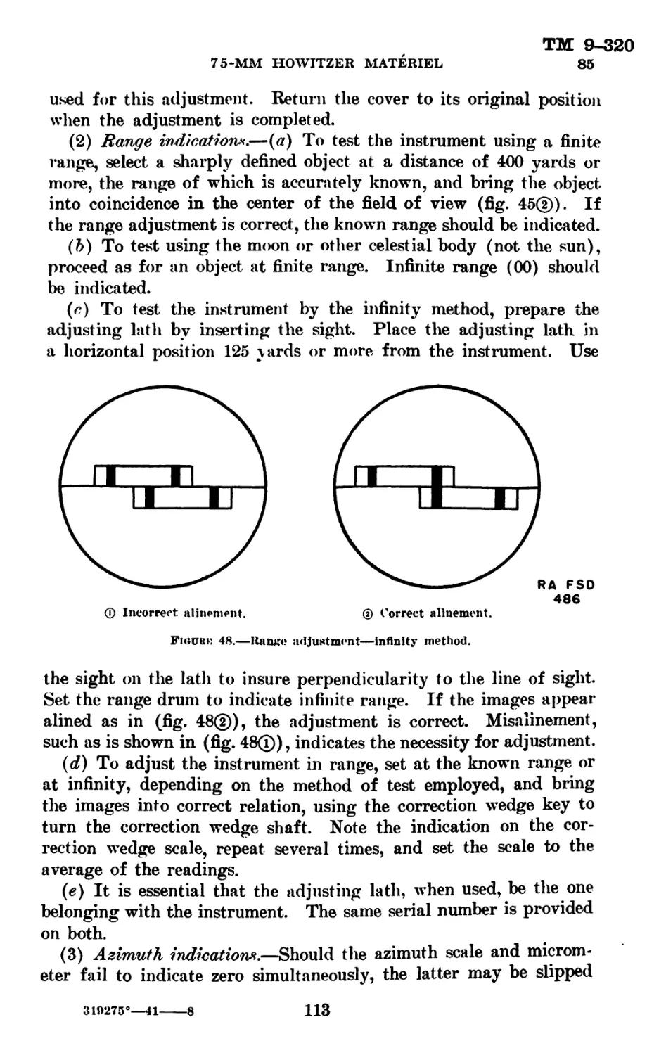
Год: 1941


Текст
*ТМ 9—320
TECHNICAL MANUAL
No. 9-320
WAR DEPARTMENT,
Washington, June 21, 1941.
75-MM HOWITZER MATERIEL
Prepared under direction of the
Chief of Ordnance
Paraffrnphs
Chapter 1. General________________________________________ 1-3
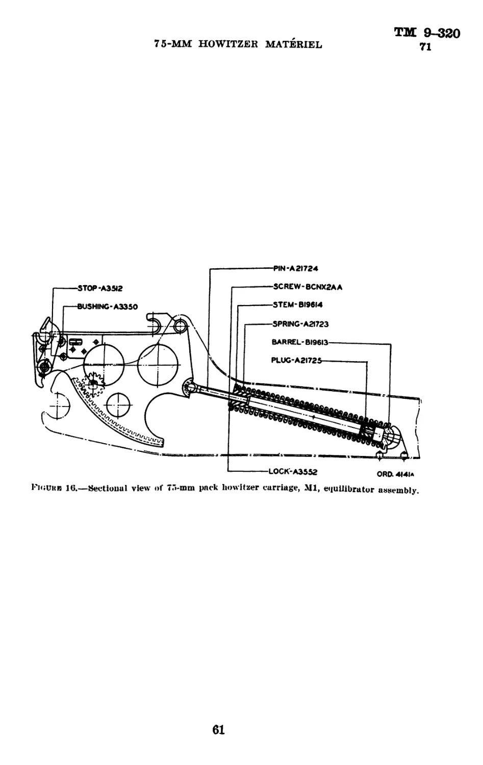
Chapter 2. Howitzers and carriages.
Section I. General information and data---------------- 4—5
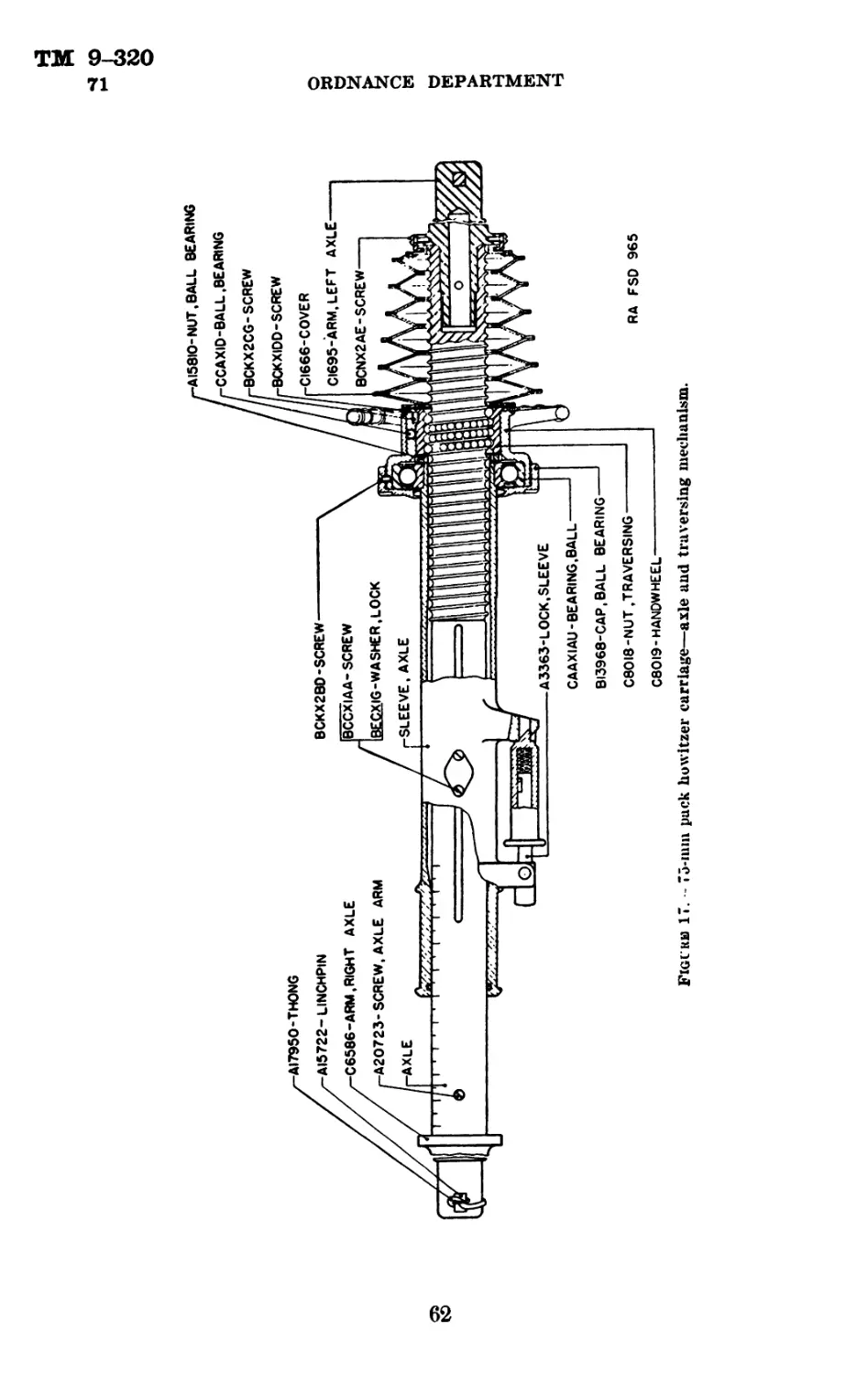
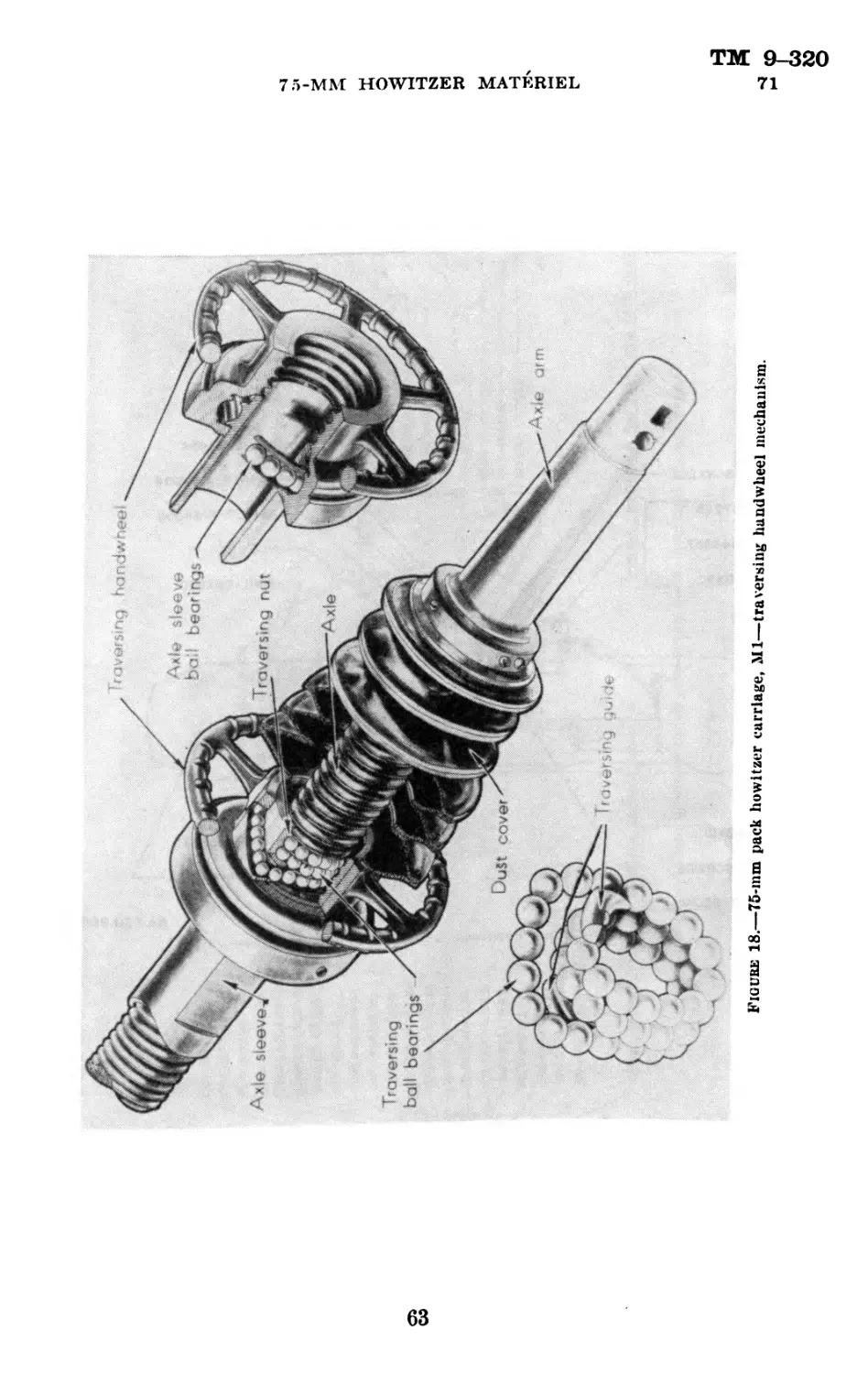
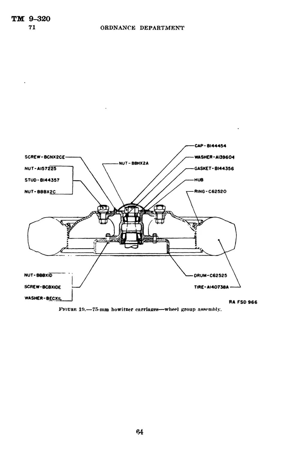
IT. Description and operation of 75-mm pack
howitzers, M1A1 and Ml-------------------- 6-10
ITT. Description and operation of 75-mm pack
howitzer carriage, Ml_____________________ 11-20
IV. Description and operation of 75-mm howitzer
carriage, M3A1__________________________________21-36
V. Description and operation of 75-mm howitzer
carriages, М3 and М2 Al------------------------37—13
VI. Disassembly and assembly____________________44-49
VII. Procedure to place materiel in firing and trav-
eling positions___________________________________50-55
VIII. Inspection and adjustment____________________ 56
IX. Malfunction and correction_________________57-59
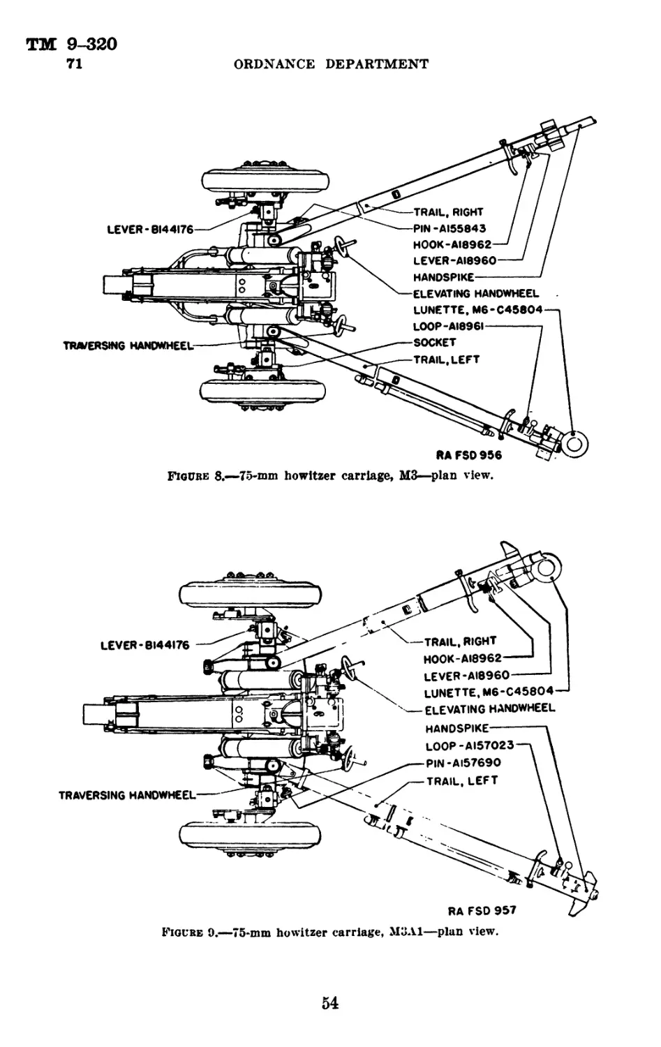
X. Care and preservation----------------------60-71
Chapter 3. Sighting and fire control equipment.
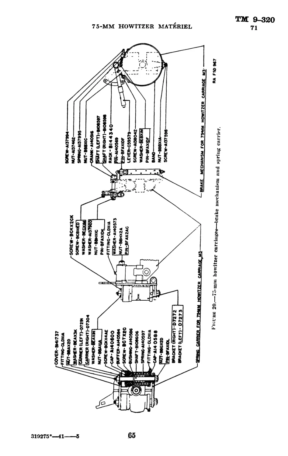
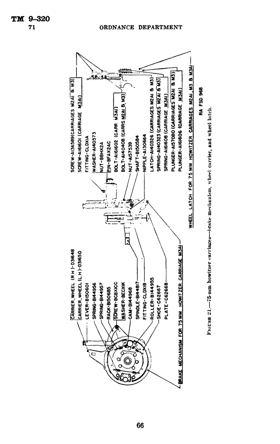
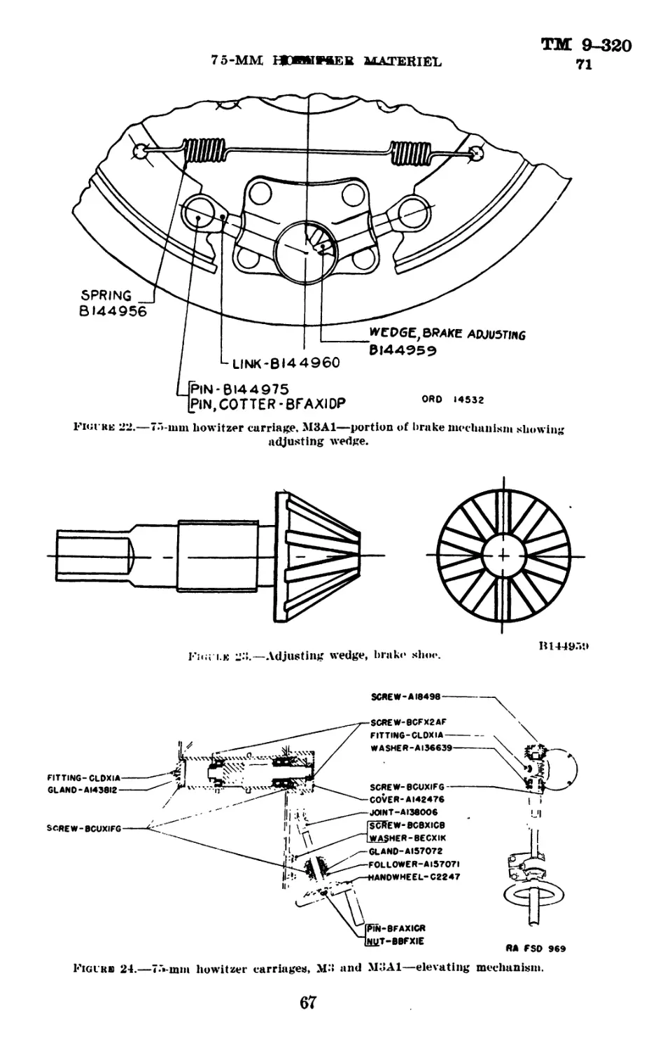
Sectton I. Sighting equipment___________________________72-82
II. Fire control equipment______________________83-91
Chapter 4. Ammunition------------------------------------92-108
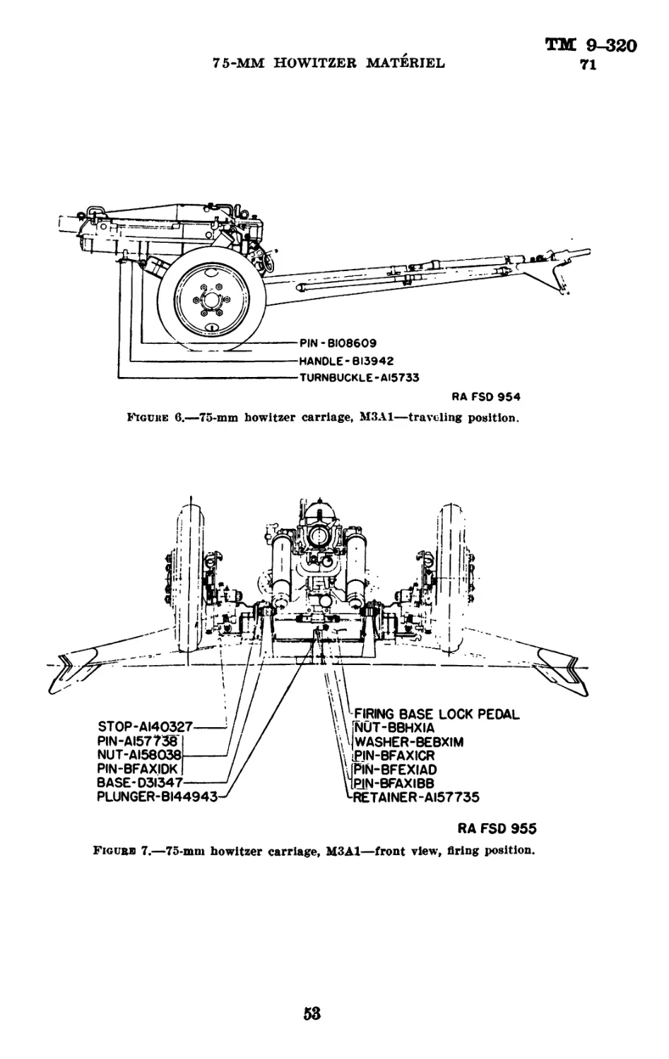
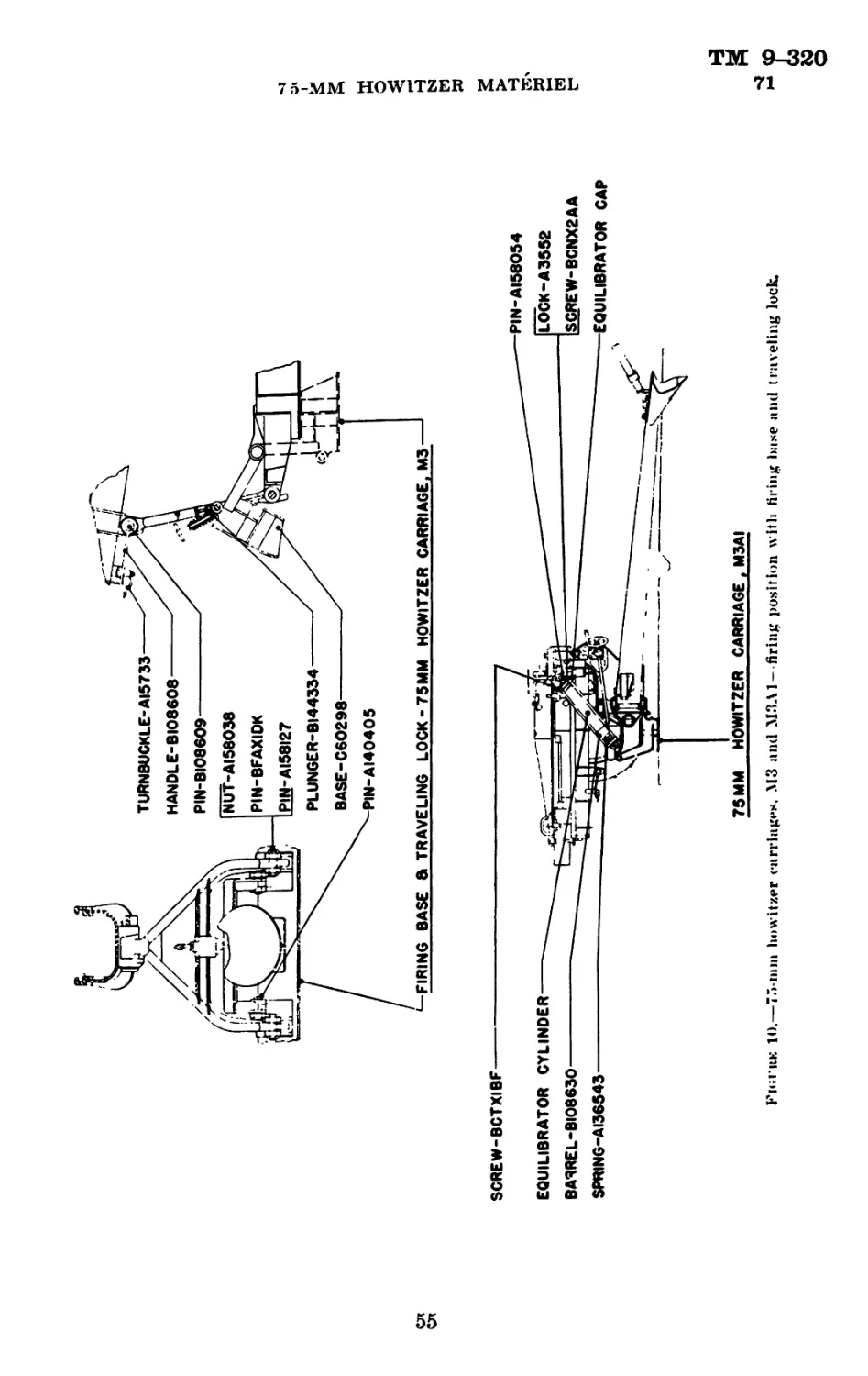
Chapter 5. Limber and caisson__________________________ 109-114
Chapter 6. Spare parts and accessories----------------- 115-116
Chapter 7. Subcaliber equipment-------------------------117-122
Chapter 8. Material affected by gas------------------------ 123
Pape
Appendix. List of references_________________________________ 153
Index________________________________________________________ 155
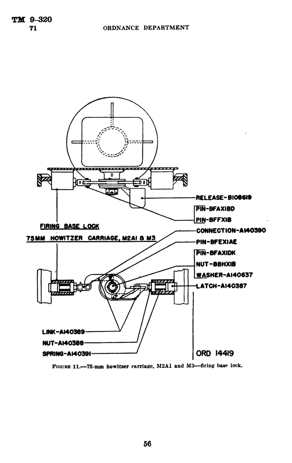
*This pamphlet supersedes TR 1305-75E, May 23. 1935.
.419271°—41-----1
ТМ 9-320
1-3
ORDNANCE DEPARTMENT
Chapter 1
GENERAL
Paragraph
Purpose__________ _________________ ________________________ 1
Scope____________ ________ _ - _______________ _______________ 2
References________________:_______________________ _________ 3
1. Purpose.—This manual is published for the information and
guidance of the using arms and services.
2. Scope.—</. This manual contains all the essential information
of a technical character required by the using arms and services for
the identification, use and care of the particular equipment described,
as well as use and care of ammunition, spare parts and accessories,
and sighting and fire control equipment.
&. Dissassembly and assembly, and repairs by battery personnel
will be undertaken only under the supervision of an officer or the
chief mechanic.
e. In cases where the nature of repair, modification, or adjustment
is beyond the scope and/or facilities of the battery personnel, the
local or otherwise designated ordnance service should be informed
in order that trained personnel with suitable tools and equipment may
be provided.
3. References.—The appendix lists all Technical Manuals, Field
Manuals, Firing Tables, Standard Nomenclature Lists, and other
publications for the materiel described herein.
2
TM 9-320
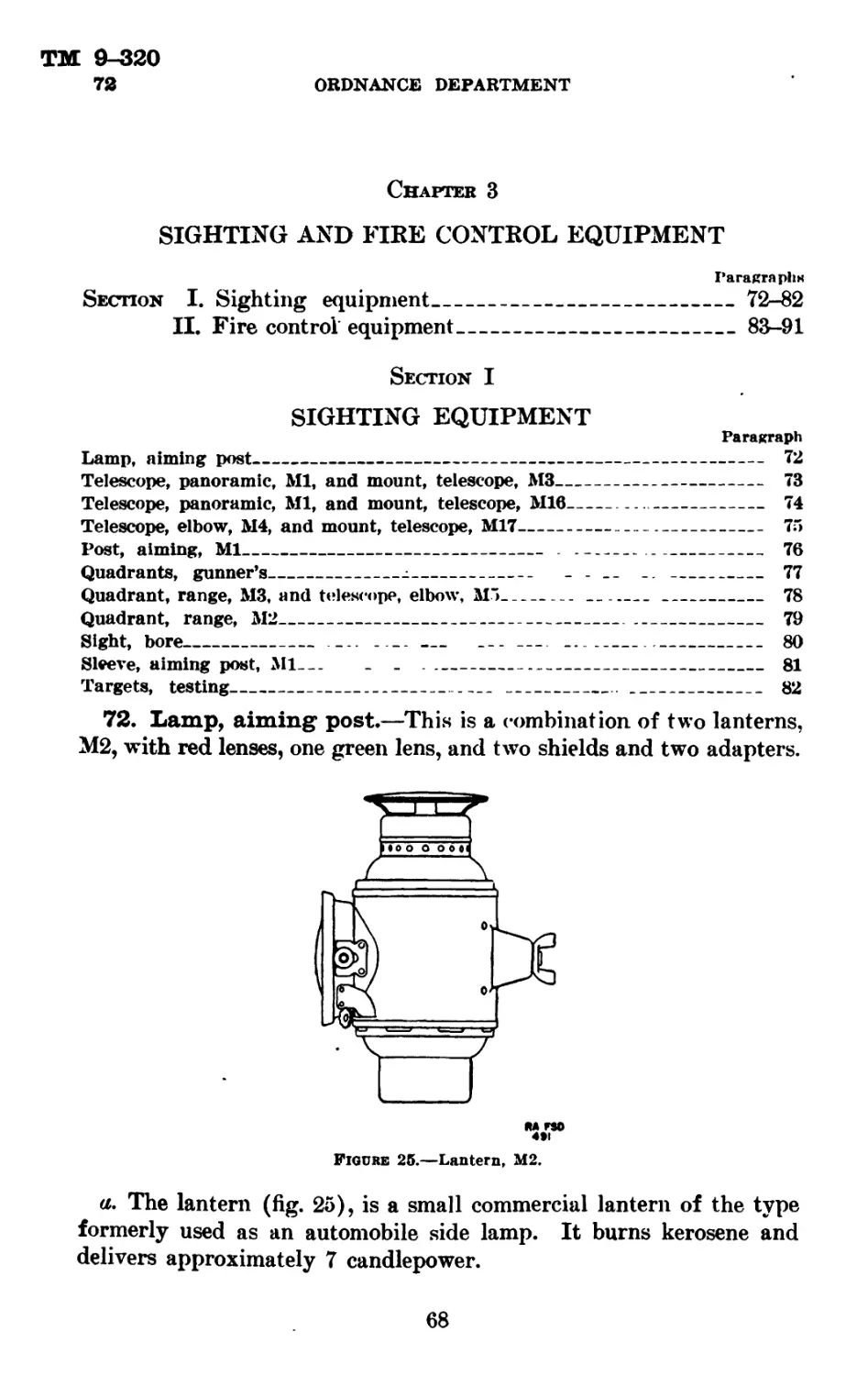
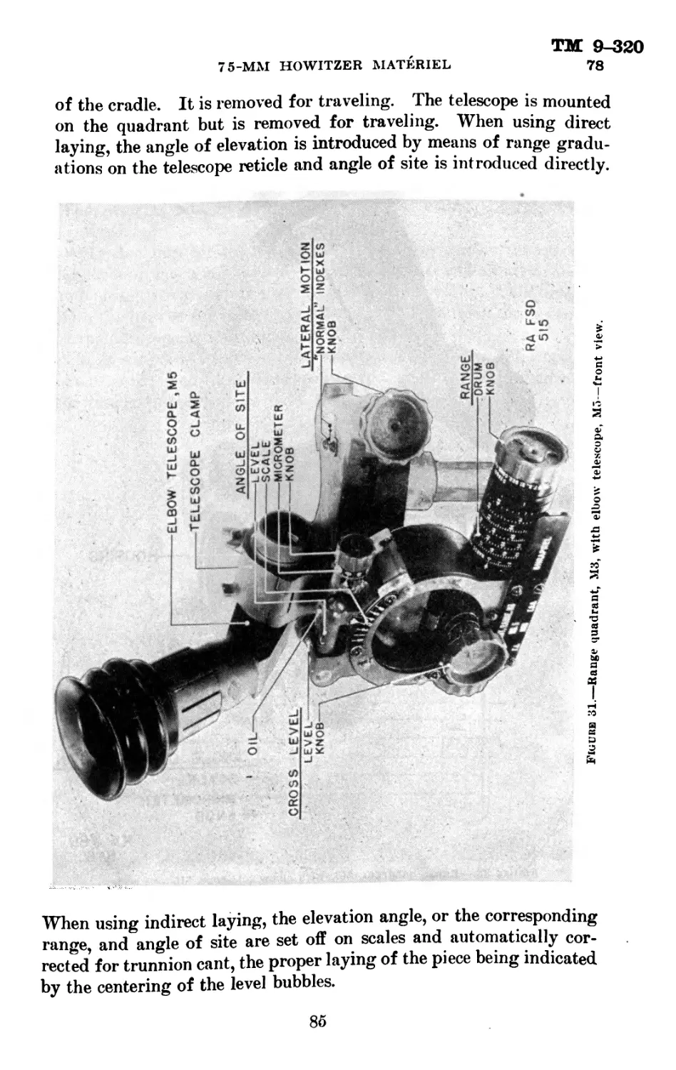
4-5
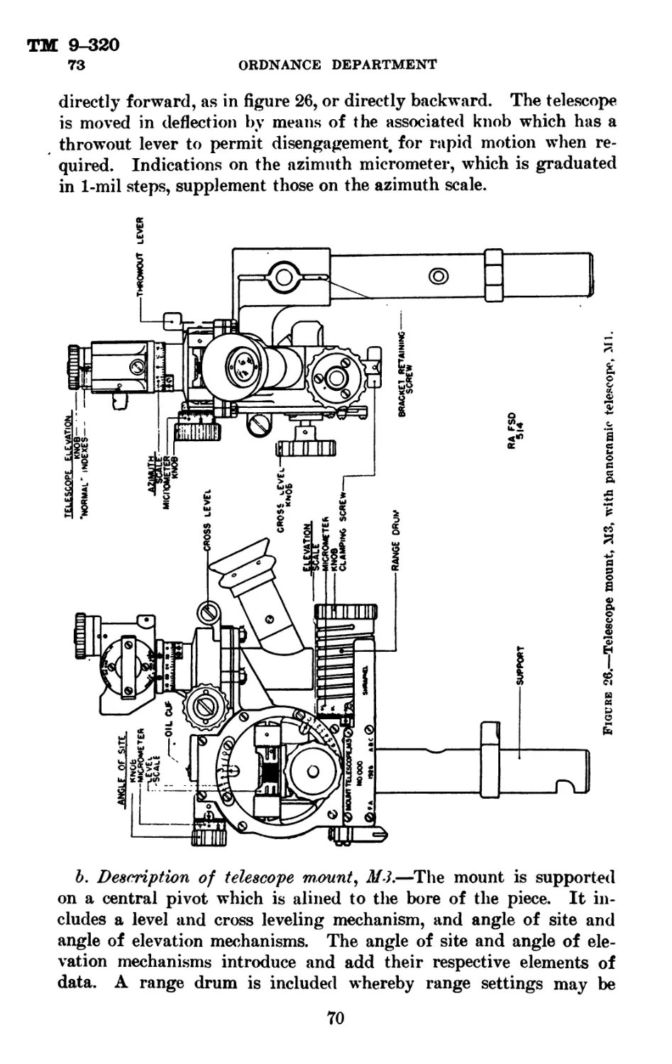
75-MM HOWITZER MATERIEL
Chapter 2
HOWITZERS AND CARRIAGES
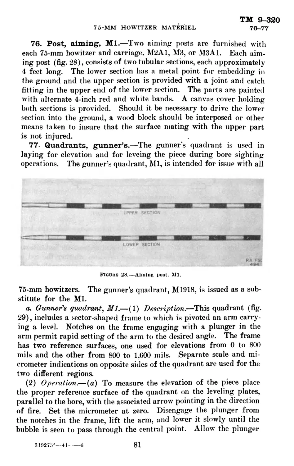
Paragraphs
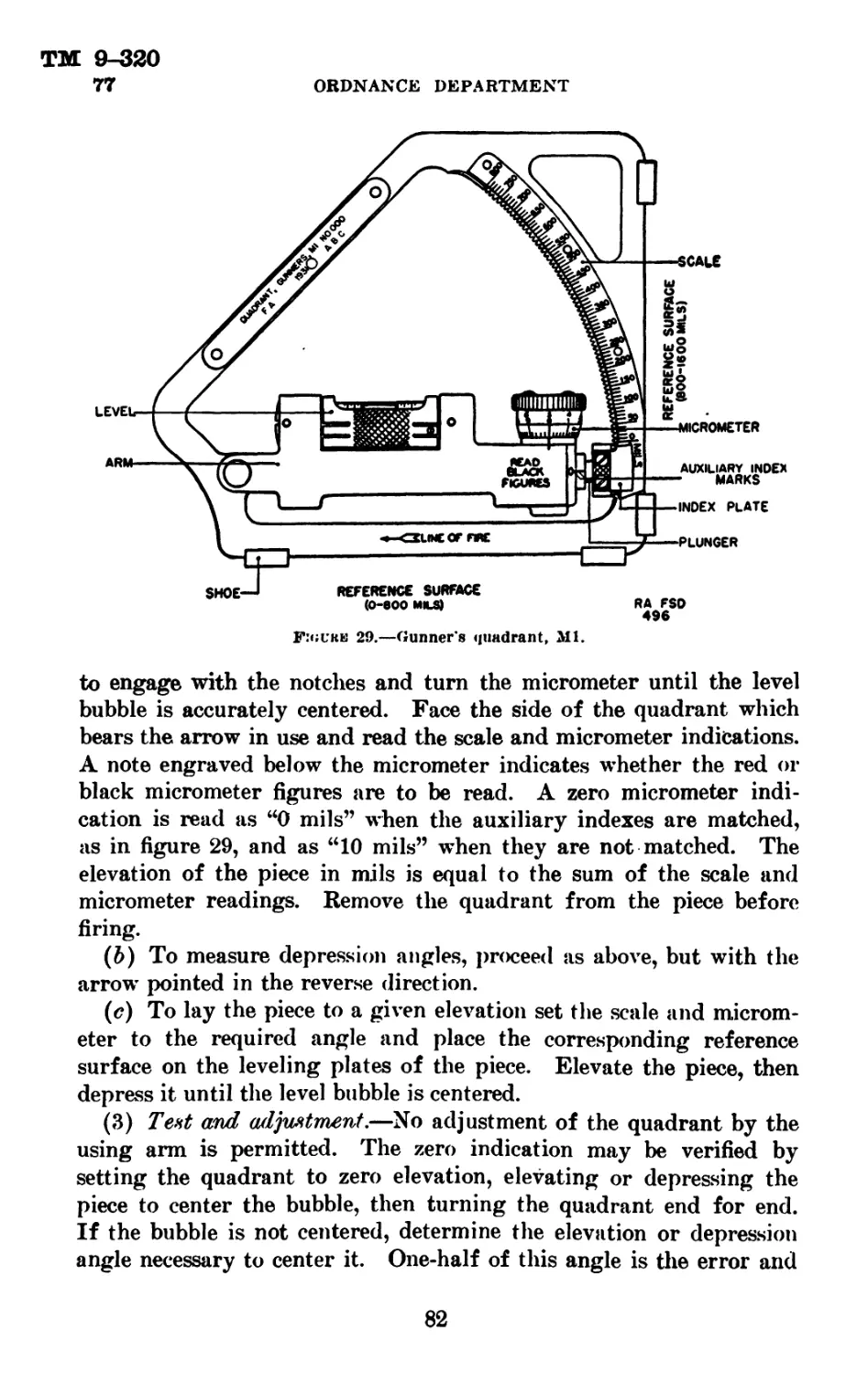
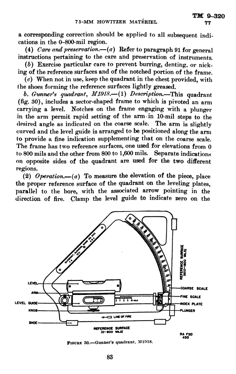
Section I. General information and data_____________________ 4-5
II. Description and operation of 75-mm pack how-
itzers, Ml Al and Ml_________________________________ 6-10
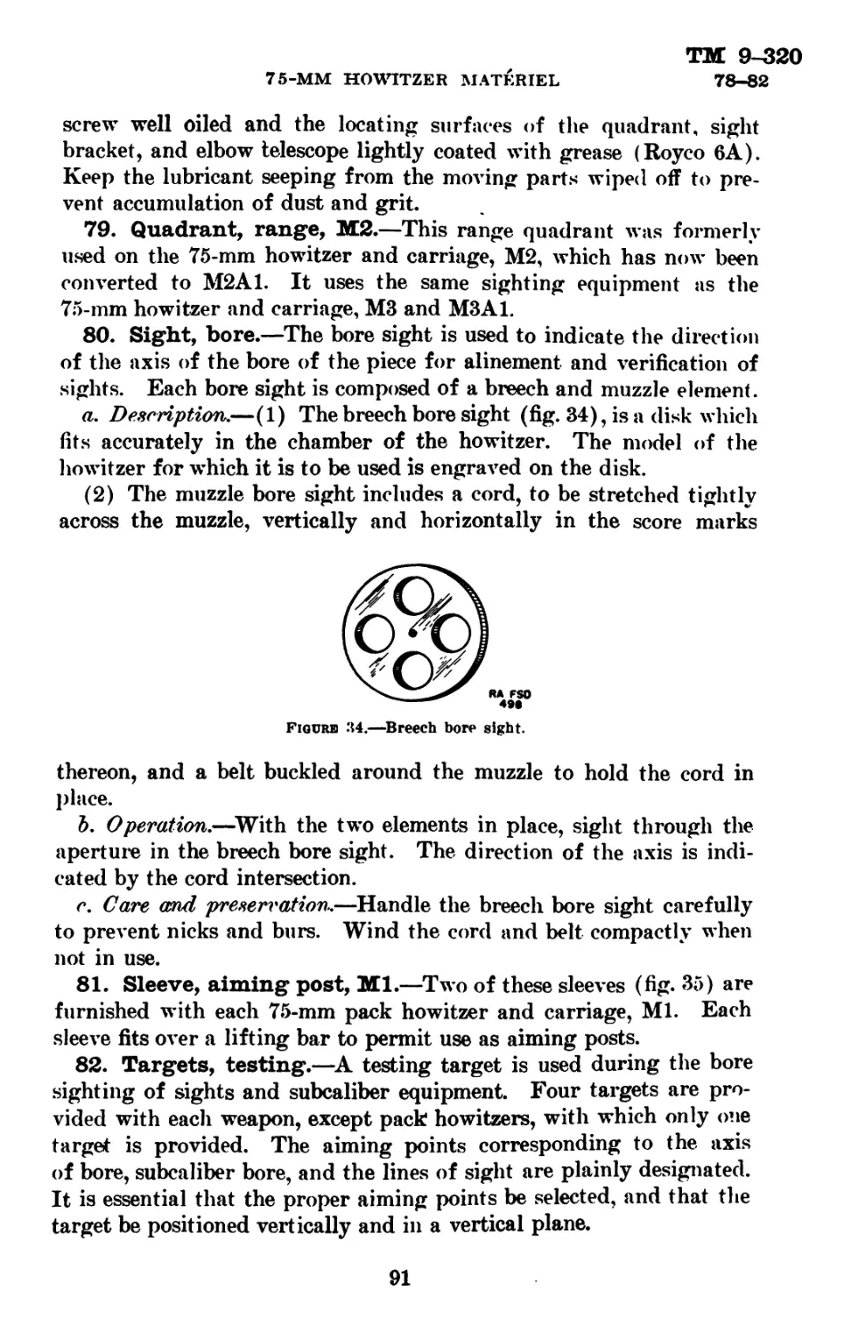
III. Description and operation of 75-mm pack howitzer
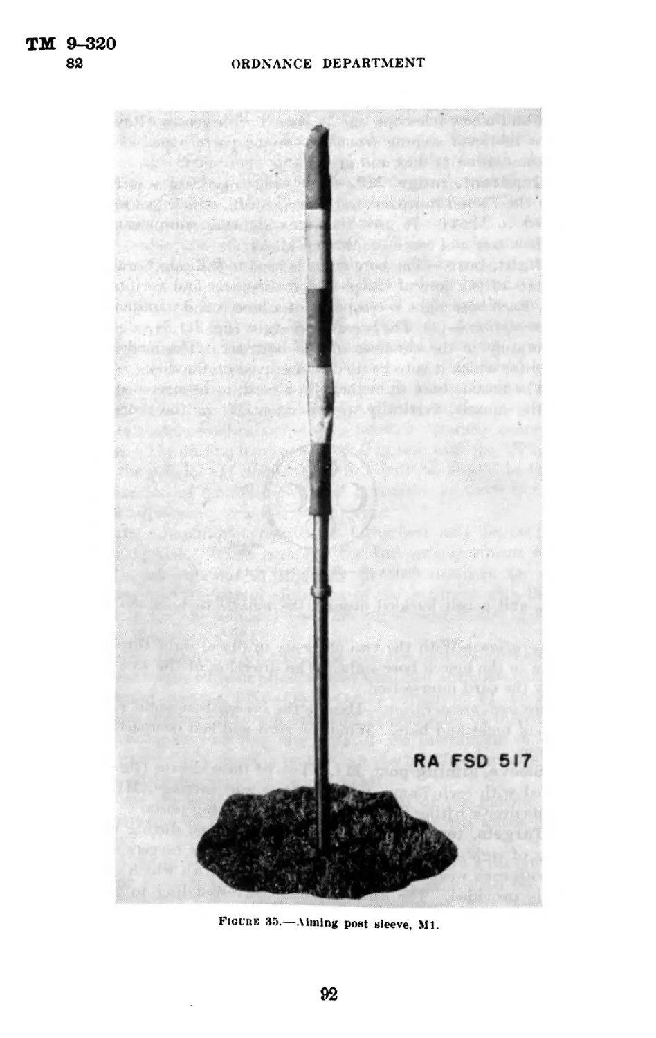
carriage, Ml__________________________________________11-20
IV. Description and operation of 75-mm howitzer car-
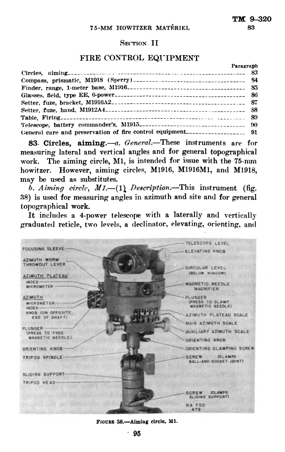
riage. M3A1__________________________________________21-36
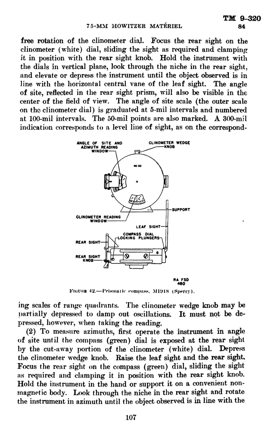
V. Description and operation of 75-mm howitzer car-
riages. М3 and М2 Al---------------------------------37-43
VI. Disassembly and assembly------------------------44-49
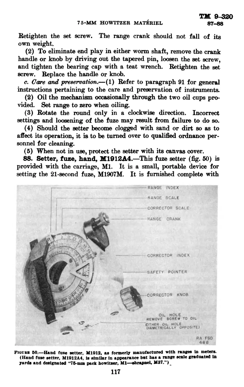
VII. Procedure to place materiel in firing and travel-
ing positions_________________________________________50-55
VIII. Inspection and adjustment------------------------- 56
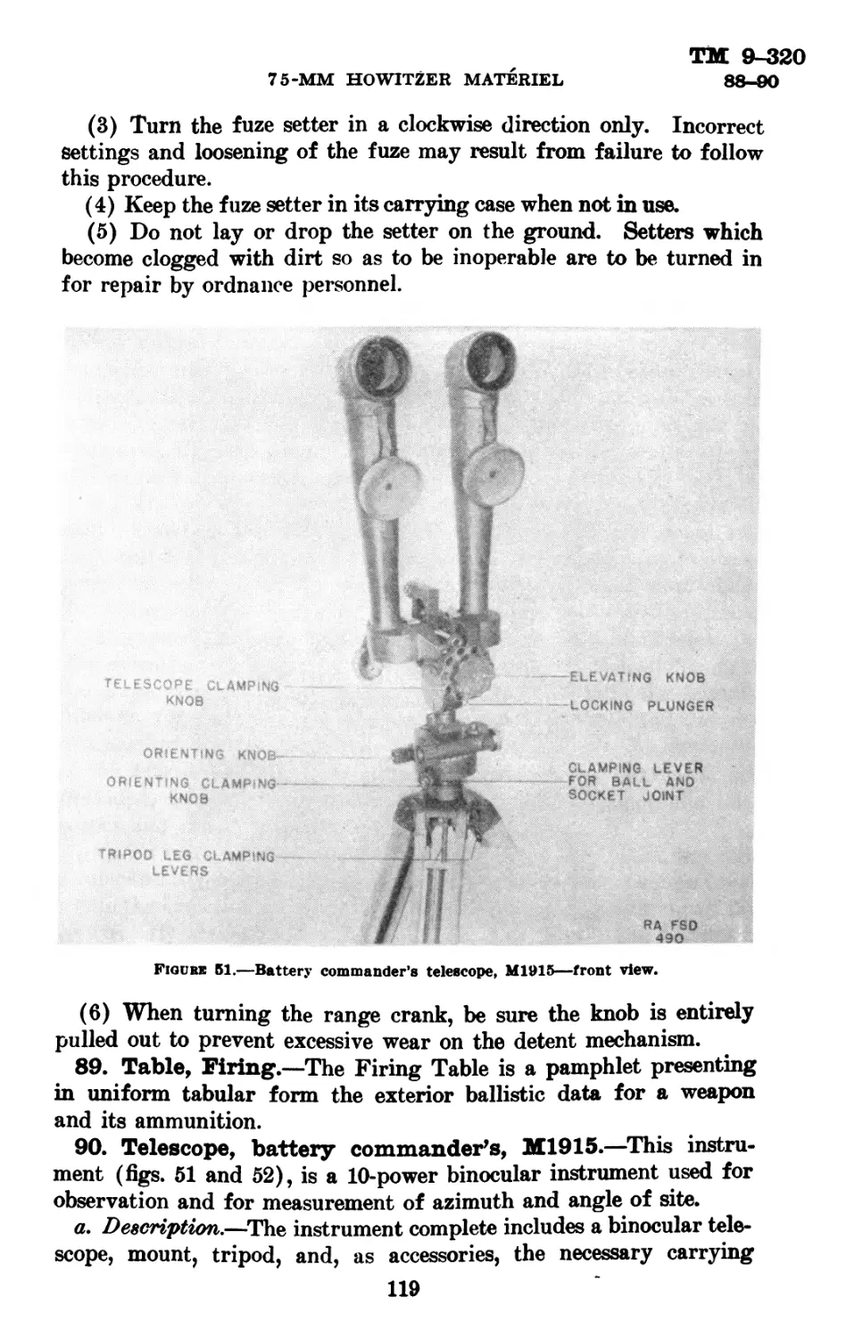
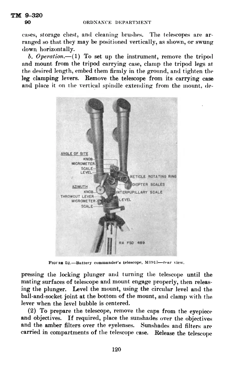
IX. Malfunction and correction----------------------57-59
X. Care and preservation---------------------------60-71
Section I
GENERAL INFORMATION AND DATA
Paragraph
General information ___________________________________ 4
Data___________________________________________________ о
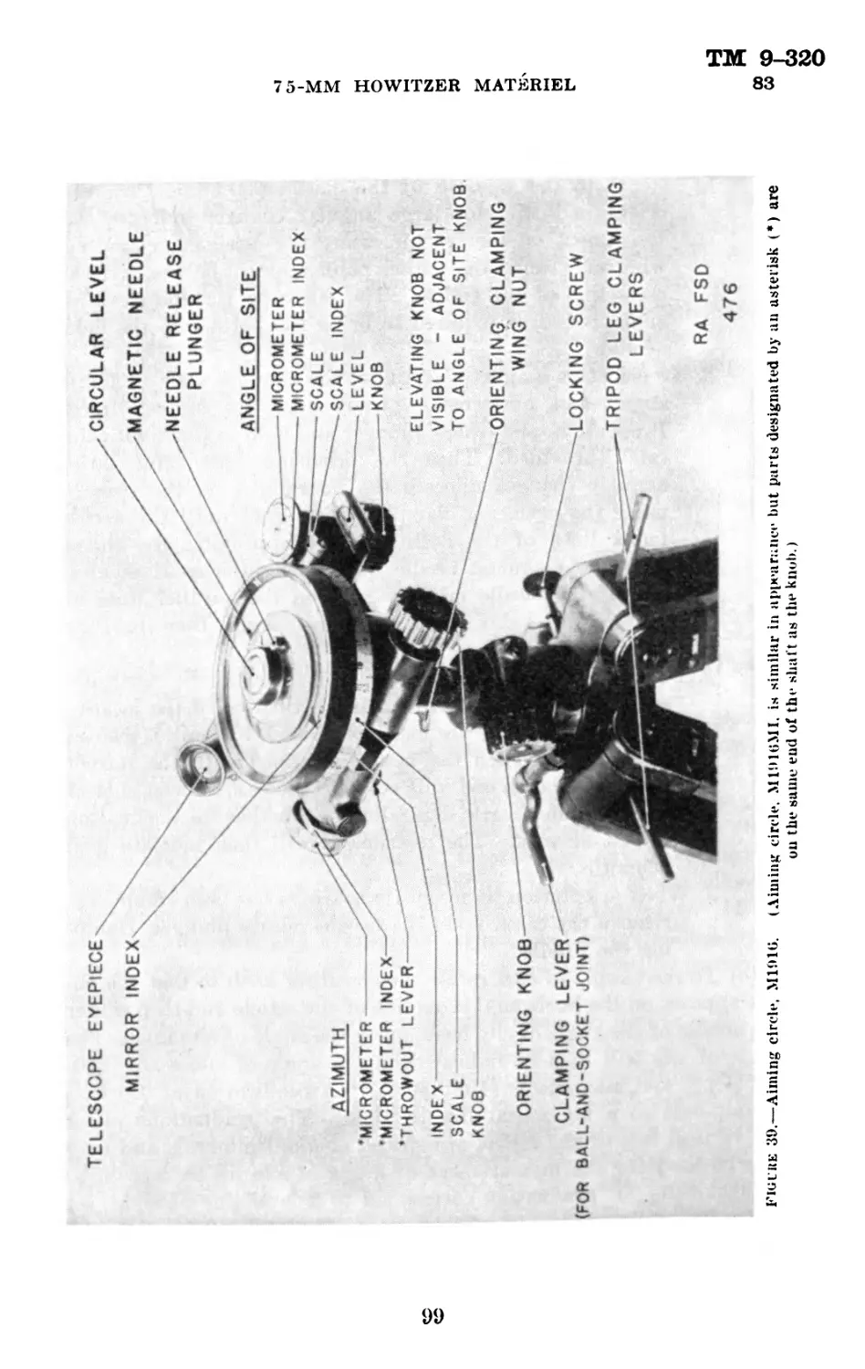
4- General Information.—The 75-mm pack howitzer is mounted
on either of two types of carriages. The 75-mm pack howitzer con-
sists of a 75-mm pack howitzer. Ml or Ml Al, mounted on a 75-mm
pack howitzer carriage, Ml; and the 75-mm field howitzer consists
of a 75-mm pack howitzer Ml or Ml Al, mounted on a 75-mm field
howitzer carriage M2A1, М3 or M3A1. The pack howitzer carriage
is arranged for dismounting into six mule-packs. This type has
wooden wheels, steel tires, and axle traversing mechanism. (See fig.
17.) The field howitzer carriage may be distinguished by its rubber
tires and firing base (fig. 10). The howitzer tube, top and bottom
sleighs, cradle and recoil mechanism are essentially the same on
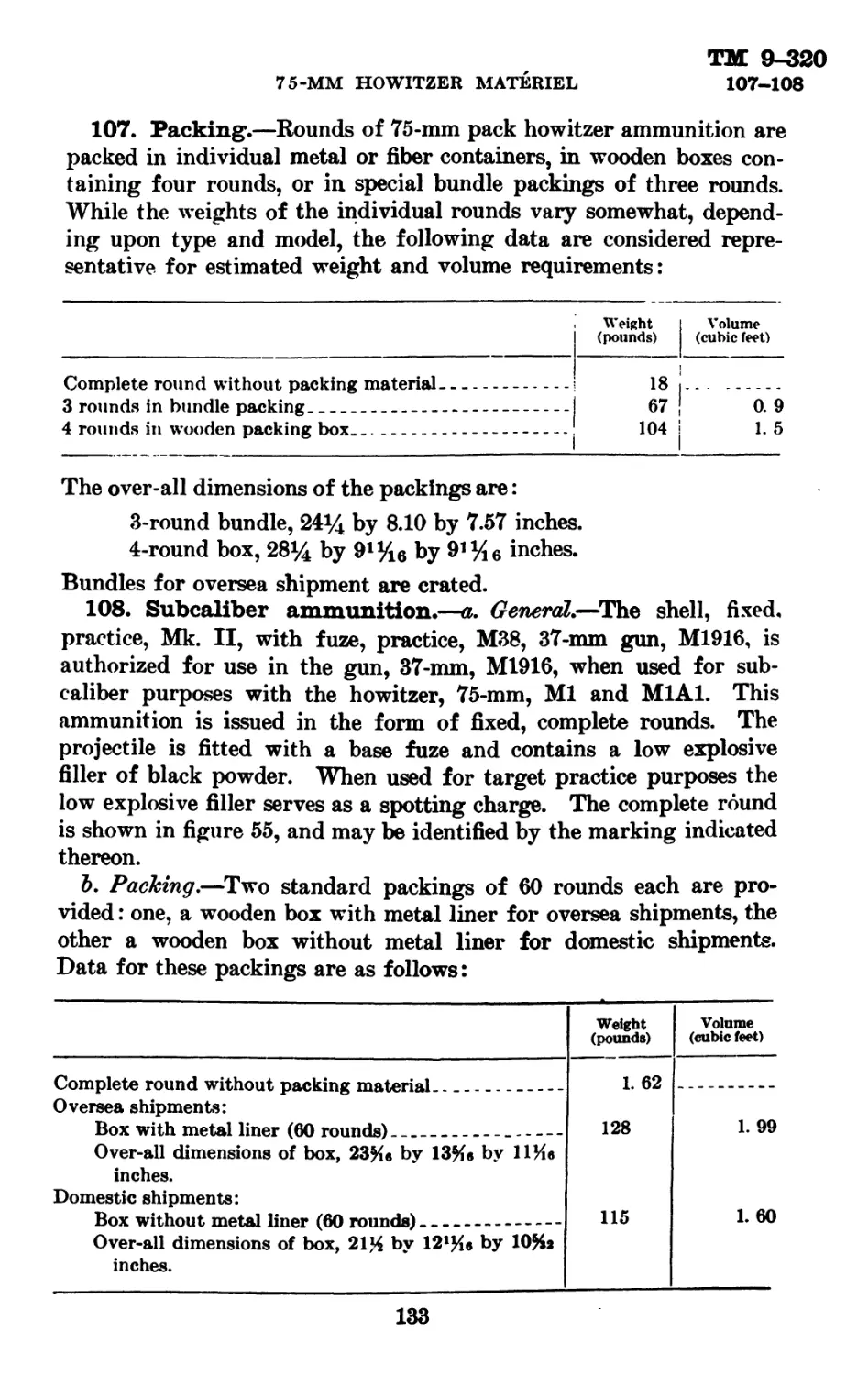
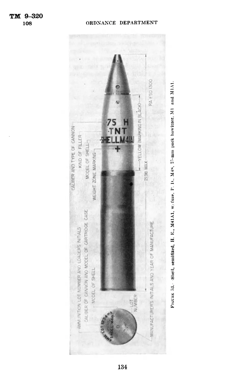
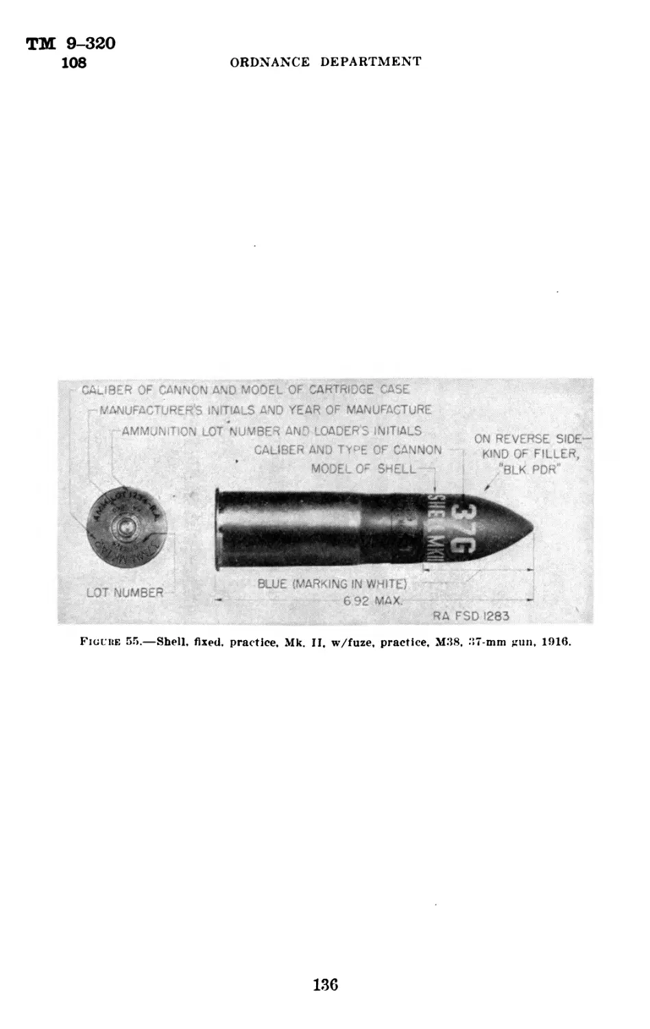
both types of carriages.
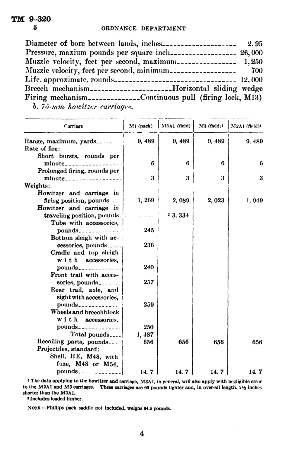
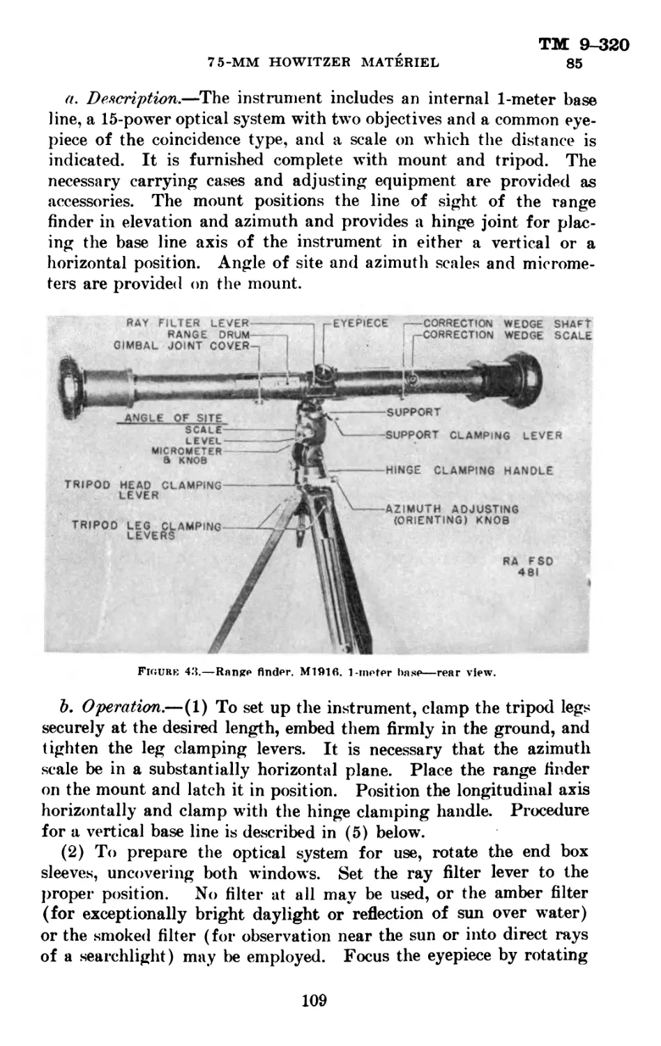
5. Data.—a, pack howitzer, M1 and MIA /.
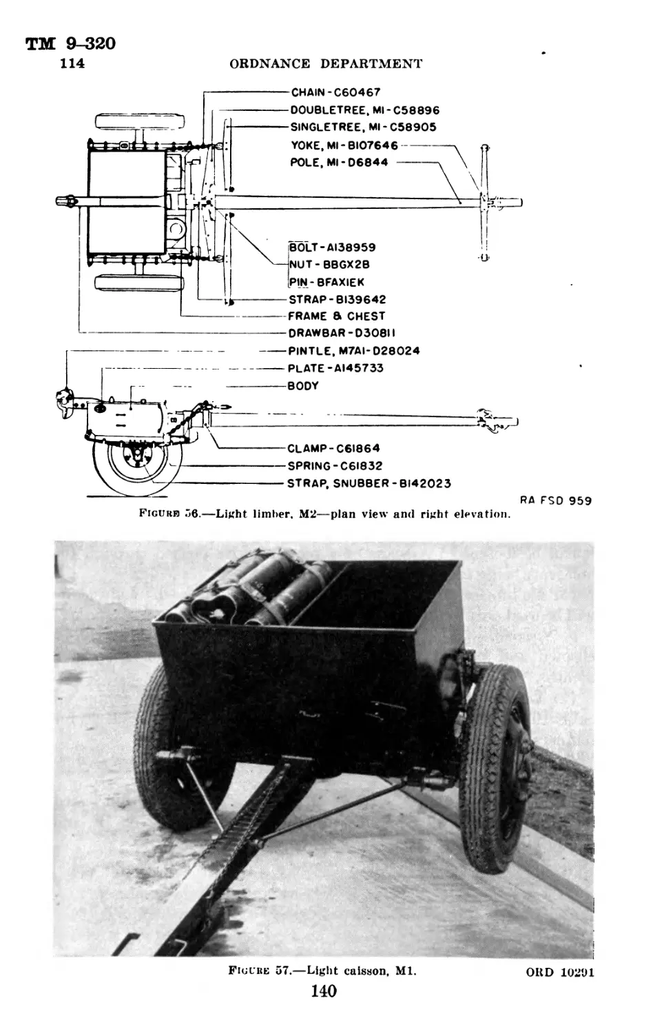
Weight with recoil mechanism, pounds_______________________ 543.56
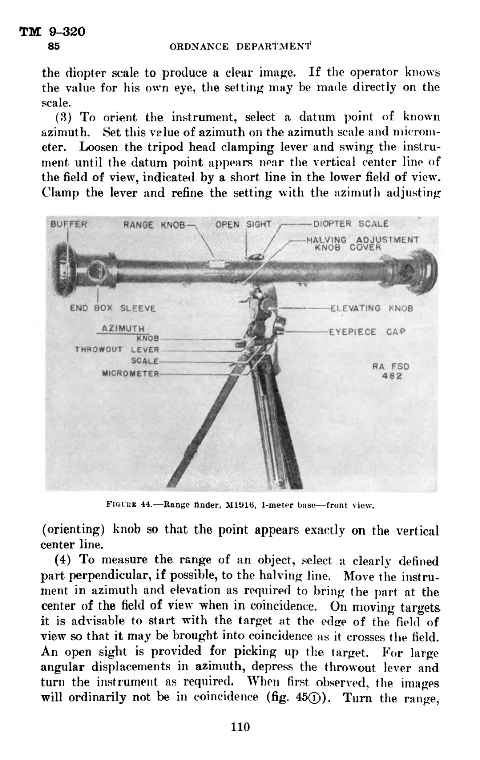
Length, calibers___________________________________________ 15.9
Rifling: Uniform, right; one turn in 20 calibers; 28 grooves,
0.03 inches deep.
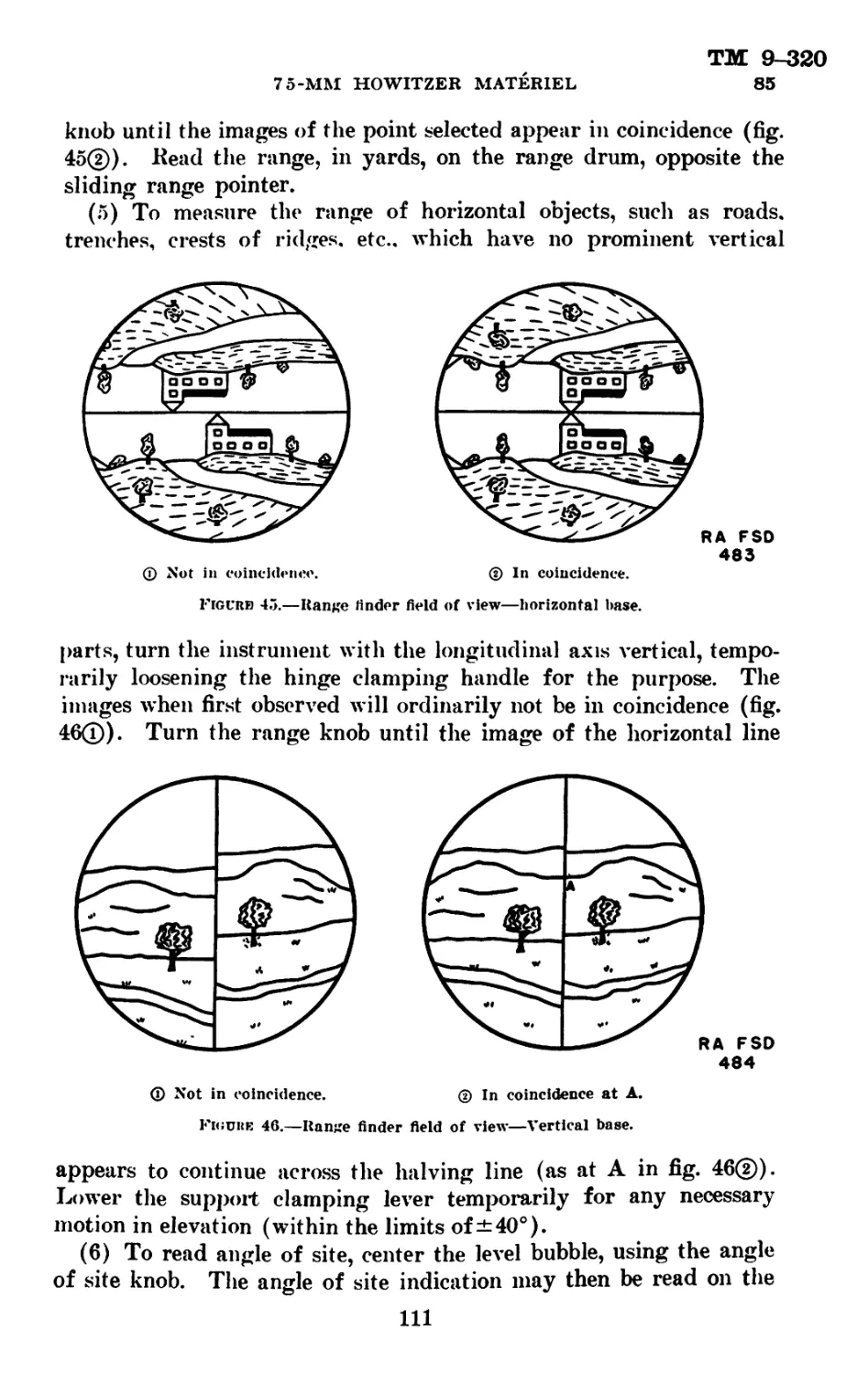
3
ТМ 9-320
5
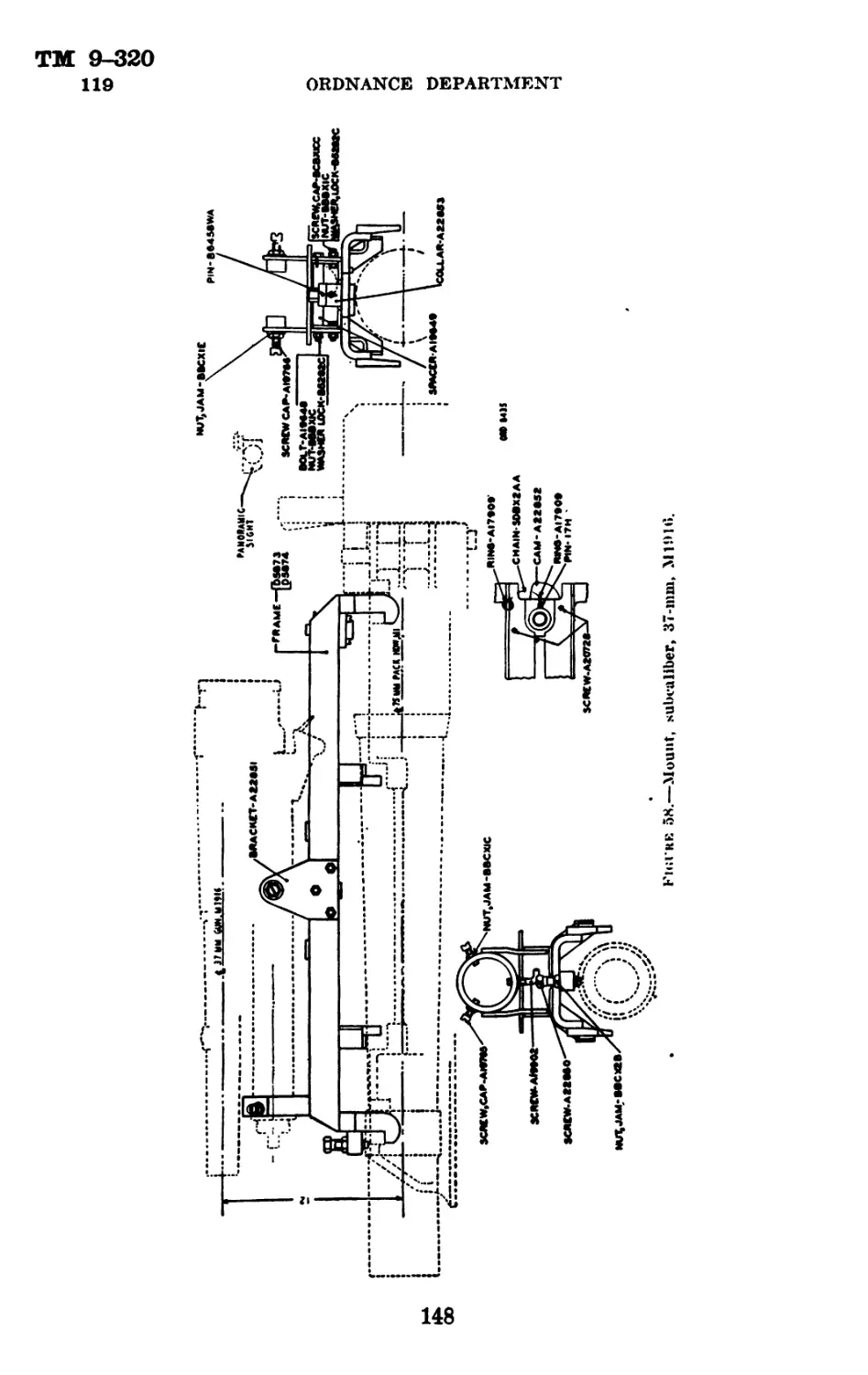
ORDNANCE DEPARTMENT
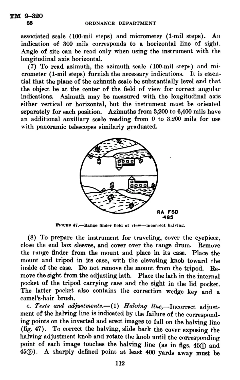
Diameter of bore between lands, inches_______________________ 2. 95
Pressure, maxium pounds per square inch----------------------26,000
Muzzle velocity, feet per second, maximum____________________ 1,250
Muzzle velocity, feet per second, minimum-------------------- 700
Life, approximate, rounds------------------------------------ 12,000
Breech mechanism_________________________Horizontal sliding wedge
Firing mechanism________________Continuous pull (firing lock, M13)
Ъ. Ч^-ттгъ howitzer carriage*.
Carriage Ml (pack) I М3 Al (field) | М3 (field)1 | M2A1 (field)»
Range, maximum, yards._ Rate of fire: Short bursts, rounds per 9, 489 9, 489 1 9, 489 9, 489
minute Prolonged firing, rounds per 6 6 6 6
minute Weights: Howitzer and carriage in 3 3 ! I 3 3
firing position, pounds Howitzer and carriage in traveling position, pounds. Tube with accessories, pounds Bottom sleigh with ac- cessories, pounds Cradle and top sleigh with accessories, pounds Front trail with acces- sories, pounds Rear trail, axle, and sight with accessories, I pounds Wheels and breechblock with accessories, pounds Total pounds 1, 269 ' 245 236 240 257 259 250 1, 487 | 2,089 ‘ 2 3, 334 2, 023 1, 949
Recoiling parts, pounds Projectiles, standard: Shell, HE, M48, with fuze, M48 or M54, 656 656 656 656
pounds 14. 7 14. 7 14. 7 14. 7
i The data applying to the howitzer and carriage, M3A1, in general, will also apply with negligible error
to the M2A1 and М3 carriages. These carriages are 66 pounds lighter and, in over-all length. 2 И inches
shorter than the M3A1.
3 Includes loaded limber.
Not®.—Phillips pack saddle not Included, weighs 94.5 pounds.
4
TM 9-320
5
75-MM HOWITZER MATERIEL
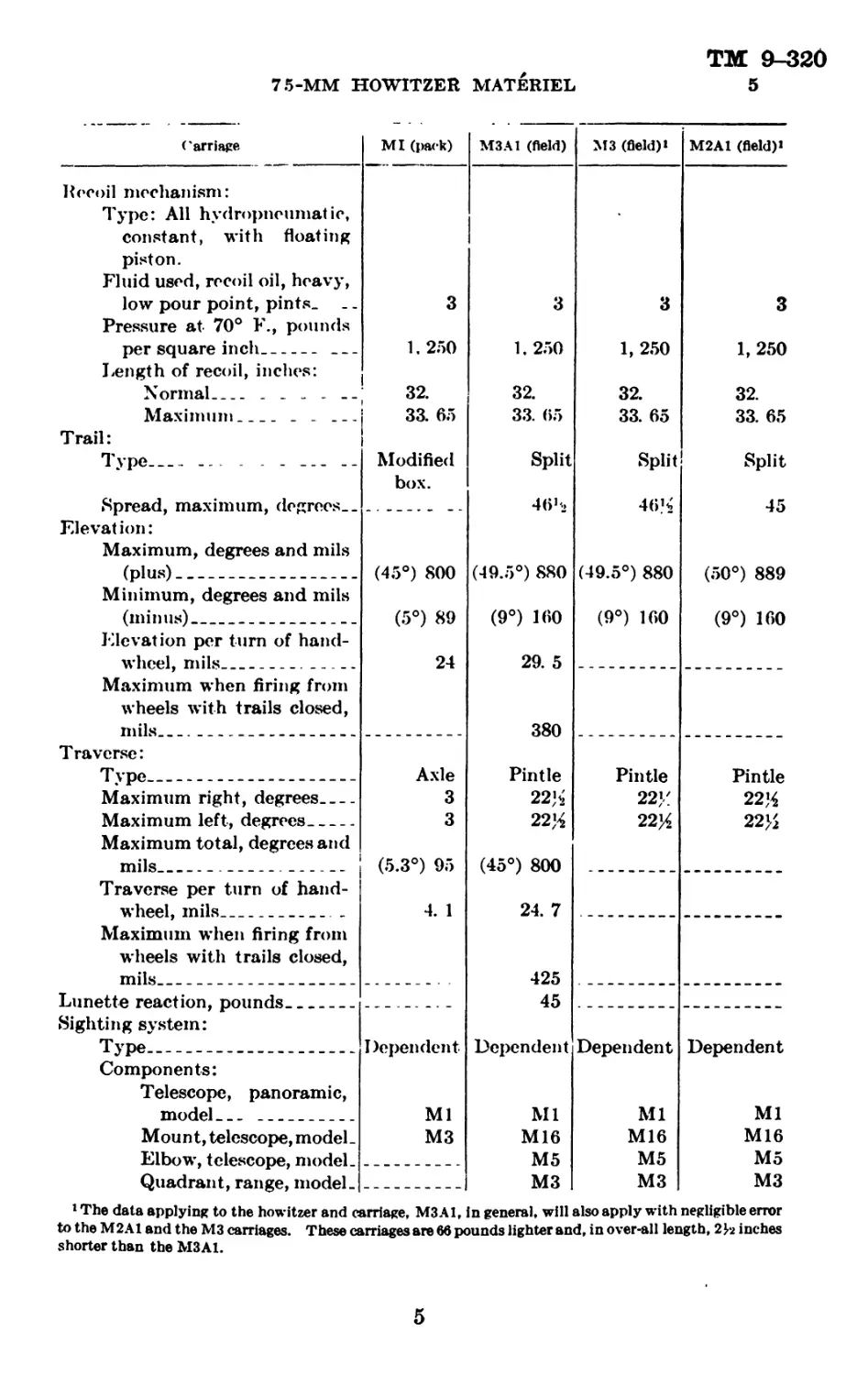
Carriage MI (pack) М3 Al (field) М3 (field)» M2A1 (field)»
Recoil mechanism: Type: All hydropneumatic, constant, with floating piston. Fluid used, recoil oil, heavy, low pour point, pints. Pressure at 70° F., pounds per square inch. _ _ 3 1, 250 3 1, 250 3 1, 250 3 1, 250 32. 33. 65 Split 45
Length of recoil, inches: Normal Maximum _ T rail: Type _,. - - - Spread, maximum, degrees. _ 32. 33. 65 Modified box. 32. 33. 05 Split 46b2 32. 33. 65 Split 46% (49.5°) 880 (9°) 100
Elevation: Maximum, degrees and mils (plus) (45°) 800 (5°) 89 24 (49.5°) 880 (9°) 100 29. 5 (50°) 889 (9°) 160
Minimum, degrees and mils (minus)
Elevation per turn of hand- wheel, mils
Maximum when firing from wheels with trails closed, mils 380
Traverse: Type Axle Pintle Pintle Pintle 22% 22%
Maximum right, degrees Maximum left, degrees Maximum total, degreesand mils 3 3 (5.3°) 95 22>; 22% (45°) 800 24. 7 22}/ 22%
Traverse per turn of hand- wheel, mils Maximum when firing from wheels with trails closed, mils 4. 1
425
Lunette reaction, pounds Sighting system: Type 45
Dependent Ml Dependent Ml Dependent Ml Dependent Ml
Components: Telescope, panoramic, model
Mount, telescope, model. Elbow, telescope, model- М3 M16 M5 M16 M5 M16 M5
Quadrant, range, model- М3 М3 М3
1 The data applying to the howitzer and carriage, M3A1, in general, will also apply with negligible error
to the М2 Al and the М3 carriages. These carriages are 66 pounds lighter and, in over-all length, 2 J-2 inches
shorter than the M3A1.
5
ТМ 9-320
5
ORDNANCE DEPARTMENT
Carriage Ml (pack) М3 Al (field) | М3 (field)* М2Л1 (field)*
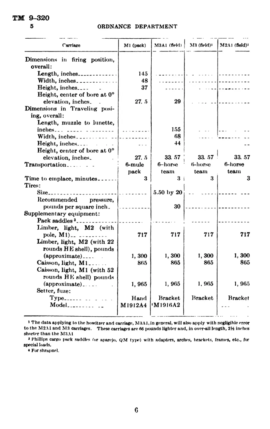
Dimensions in firing position, overall: Length, inches 145 48 37 27. 5
Width, inches
Height, inches Height, center of bore at 0° elevation, inches. Dimensions in Traveling posi- ing, overall: Length, muzzle to lunette, inches 29 155 68 44 33. 57 6-horse team 3 i 5.50 by 20 30 717 1,300 865 1, 965 Bracket ‘M1916A2
; 33.57 6-horse team i 3 1 33.57 6-horse team 3
Width, inches — -- Height, inches Height, center of bore at 0° elevation, inches. Transportation Time to emplace, minutes 27. 5 6-mule pack 3
Tires: Size
Recommended pressure, pounds per square inch. Supplementary equipment: Pack saddles3
717 1,300 865 1, 965 Bracket 717 1,300 865 1, 965 Bracket
Limber, light, М2 (with pole, Ml)_. Limber, light, М2 (with 22 rounds HE shell), pounds (approximate) Caisson, light, Ml . Caisson, light, M1 (with 52 rounds HE shell) pounds (approximate).. ... Setter, fuze: Type . ... Model __ 717 1, 300 865 1,965 Hand M1912A4
1 The data applying to the howitzer and carriage, MЗА 1, in genera], will also apply with negligible error
to the М2Л1 and М3 carriages. These carriages are 66 pounds lighter and, in over-ail length, 2Ц inches
shorter than the МЗЛ1
8 Phillips cargo pack saddles /or aparejo. QM tyf>e) with adapters, arches, brackets, frames, etc., for
special loads.
< For shrapnel.
TM 9-320
6-8
75-MM HOWITZER MATERIEL
Section II
DESCRIPTION AND OPERATION OF 75-MM PACK
HOWITZERS, M1A1 AND Ml
Pa fit graph
75-mm pack howitzer. M1A1_ --------------- -------- — - 6
Tube assembly_________________ __________________ _______ ______ 7
Breech mechanism..------ .. -------- ----------... ------- 8
Firing Jock, M13------------------------------------- ---------- 9
75-mm pack howitzer. Ml---- - ------ ... ---------- ------------ 10
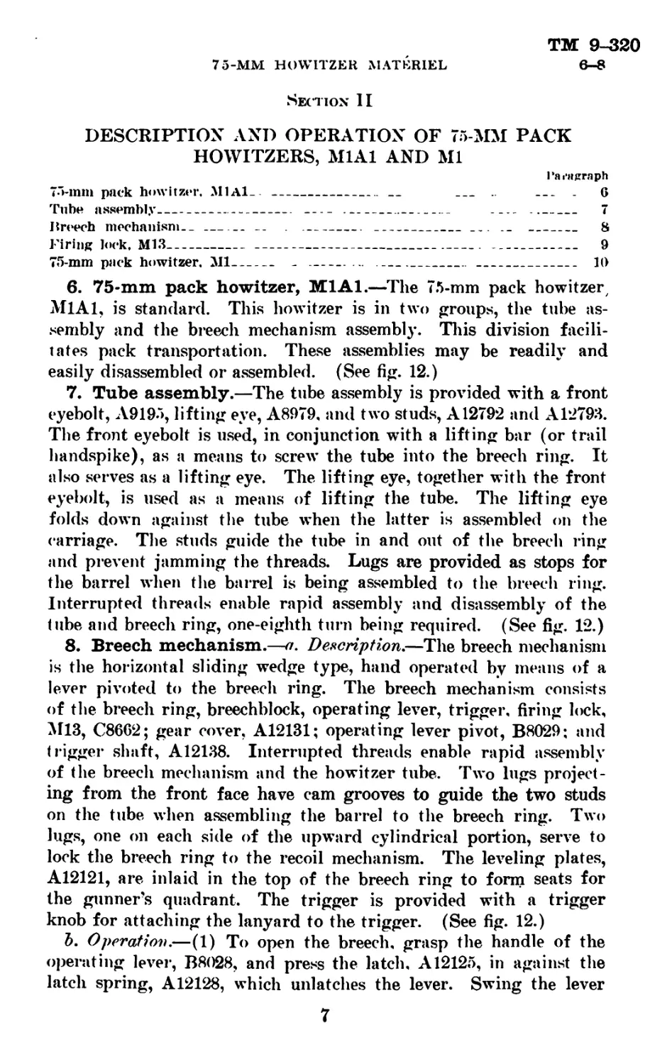
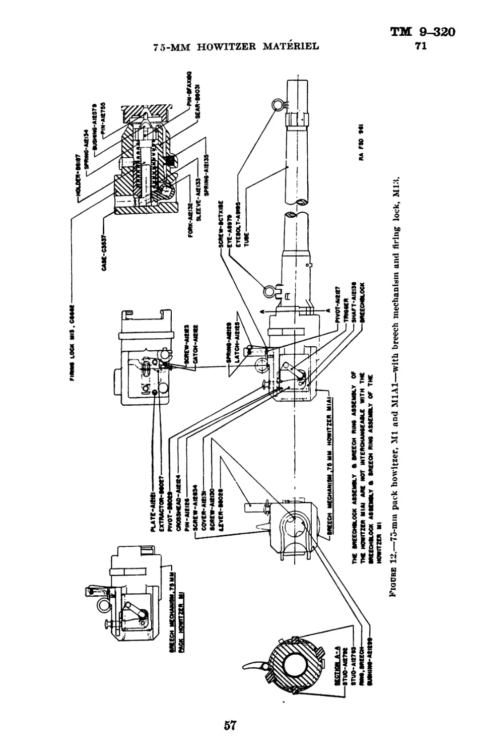
6. 75-mm pack howitzer, Ml Al.—The 75-mm pack howitzer
M1A1, is standard. This howitzer is in two groups, the tube as-
sembly and the breech mechanism assembly. This division facili-
tates pack transportation. These assemblies may be readily and
easily disassembled or assembled. (See fig. 12.)
7. Tube assembly.—The tube assembly is provided with a front
eyebolt, A9195, lifting eye, A8979. and two studs, A12792 and A12793.
The front eyebolt is used, in conjunction writh a lifting bar (or trail
handspike), as a means to screw the tube into the breech ring. It
also serves as a lifting eye. The lifting eye, together with the front
eyebolt, is used as a means of lifting the tube. The lifting eye
folds down against the tube when the latter is assembled on the
carriage. The studs guide the tube in and out of the breech ring
and prevent jamming the threads. Lugs are provided as stops for
the barrel when the barrel is being assembled to the breech ring.
Interrupted threads enable rapid assembly and disassembly of the
tube and breech ring, one-eighth turn being required. (See fig. 12.)
8. Breech mechanism.—a. Description.—The breech mechanism
is the horizontal sliding wedge type, hand operated by means of a
lever pivoted to the breech ring. The breech mechanism consists
of the breech ring, breechblock, operating lever, trigger, firing lock,
M13, C86G2; gear cover, A12131; operating lever pivot, B8029; and
trigger shaft, A12138. Interrupted threads enable rapid assembly
of the breech mechanism and the howitzer tube. Two lugs project-
ing from the front face have cam grooves to guide the two studs
on the tube when assembling the barrel to the breech ring. Two
lugs, one on each side of the upward cylindrical portion, serve to
lock the breech ring to the recoil mechanism. The leveling plates,
A12121, are inlaid in the top of the breech ring to form seats for
the gunner’s quadrant. The trigger is provided with a trigger
knob for attaching the lanyard to the trigger. (See fig. 12.)
b. Operation.—(1) To open the breech, grasp the handle of the
operating lever, B8028, and press the latch. A12125, in against the
latch spring, A12128, which unlatches the lever. Swing the lever
7
ТМ 9-320
8-9
ORDNANCE DEPARTMENT
to the right and around to the rear until it strikes the breech ring.
As the breechblock moves to the open position it actuates the extrac-
tor, B8027, which ejects the cartridge case. In opening the breech
rapidly the operator should retain his hold on the lever to prevent
Rebound of the breechblock.
(2) To close the breech, reverse the manipulation of the operating
lever.
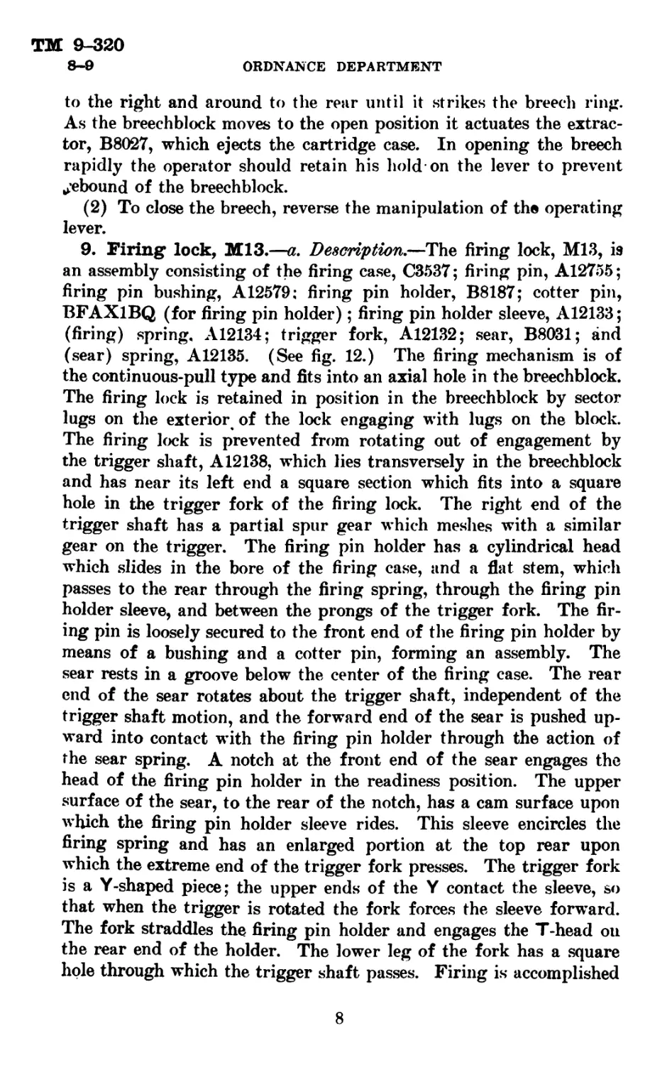
9. Firing lock, M13.—a. Description.—The firing lock, M13, is
an assembly consisting of the firing case, C3537; firing pin, A12755;
firing pin bushing, A12579; firing pin holder, B8187; cotter pin,
BFAX1BQ (for firing pin holder); firing pin holder sleeve, A12133;
(firing) spring. A12134; trigger fork, A12132; sear, B8031; and
(sear) spring, A12135. (See fig. 12.) The firing mechanism is of
the continuous-pull type and fits into an axial hole in the breechblock.
The firing lock is retained in position in the breechblock by sector
lugs on the exterior of the lock engaging with lugs on the block.
The firing lock is prevented from rotating out of engagement by
the trigger shaft, A12138, which lies transversely in the breechblock
and has near its left end a square section which fits into a square
hole in the trigger fork of the firing lock. The right end of the
trigger shaft has a partial spur gear which meshes with a similar
gear on the trigger. The firing pin holder has a cylindrical head
which slides in the bore of the firing case, and a flat stem, which
passes to the rear through the firing spring, through the firing pin
holder sleeve, and between the prongs of the trigger fork. The fir-
ing pin is loosely secured to the front end of the firing pin holder by
means of a bushing and a cotter pin, forming an assembly. The
sear rests in a groove below the center of the firing case. The rear
end of the sear rotates about the trigger shaft, independent of the
trigger shaft motion, and the forward end of the sear is pushed up-
ward into contact with the firing pin holder through the action of
the sear spring. A notch at the front end of the sear engages the
head of the firing pin holder in the readiness position. The upper
surface of the sear, to the rear of the notch, has a cam surface upon
which the firing pin holder sleeve rides. This sleeve encircles the
firing spring and has an enlarged portion at the top rear upon
which the extreme end of the trigger fork presses. The trigger fork
is a Y-shaped piece; the upper ends of the Y contact the sleeve, so
that when the trigger is rotated the fork forces the sleeve forward.
The fork straddles the firing pin holder and engages the T-head on
the rear end of the holder. The lower leg of the fork has a square
hole through which the trigger shaft passes. Firing is accomplished
8
TM &-320
9-10
75-MM HOWITZER MATERIEL
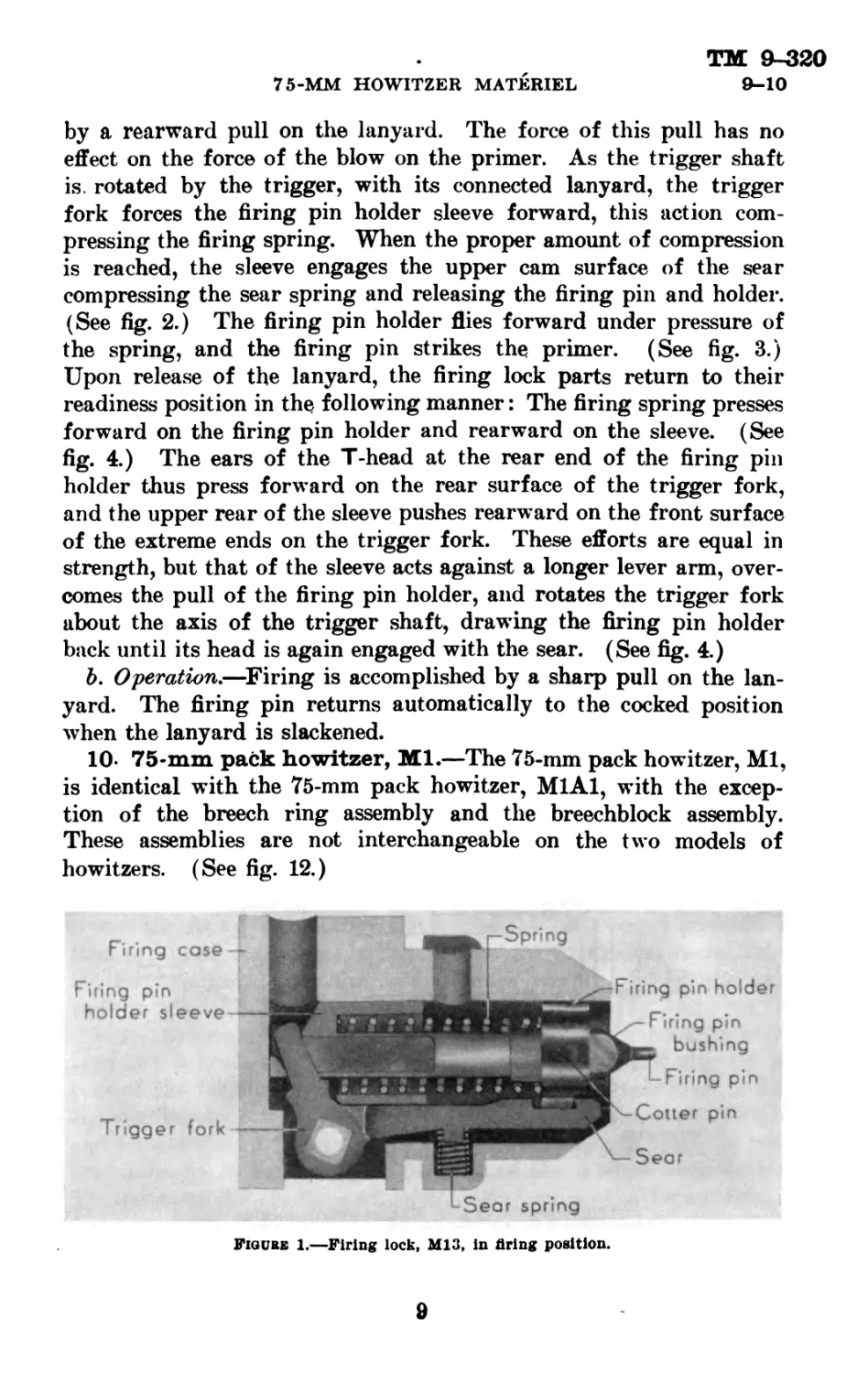
by a rearward pull on the lanyard. The force of this pull has no
effect on the force of the blow on the primer. As the trigger shaft
is. rotated by the trigger, with its connected lanyard, the trigger
fork forces the firing pin holder sleeve forward, this action com-
pressing the firing spring. When the proper amount of compression
is reached, the sleeve engages the upper cam surface of the sear
compressing the sear spring and releasing the firing pin and holder.
(See fig. 2.) The firing pin holder flies forward under pressure of
the spring, and the firing pin strikes the primer. (See fig. 3.)
Upon release of the lanyard, the firing lock parts return to their
readiness position in the following manner: The firing spring presses
forward on the firing pin holder and rearward on the sleeve. (See
fig. 4.) The ears of the T-head at the rear end of the firing pin
holder thus press forward on the rear surface of the trigger fork,
and the upper rear of the sleeve pushes rearward on the front surface
of the extreme ends on the trigger fork. These efforts are equal in
strength, but that of the sleeve acts against a longer lever arm, over-
comes the pull of the firing pin holder, and rotates the trigger fork
about the axis of the trigger shaft, drawing the firing pin holder
back until its head is again engaged with the sear. (See fig. 4.)
ft. Operation.—Firing is accomplished by a sharp pull on the lan-
yard. The firing pin returns automatically to the cocked position
when the lanyard is slackened.
10- 75-mm pack howitzer, Ml.—The 75-mm pack howitzer, Ml,
is identical with the 75-mm pack howitzer, M1A1, with the excep-
tion of the breech ring assembly and the breechblock assembly.
These assemblies are not interchangeable on the two models of
howitzers. (See fig. 12.)
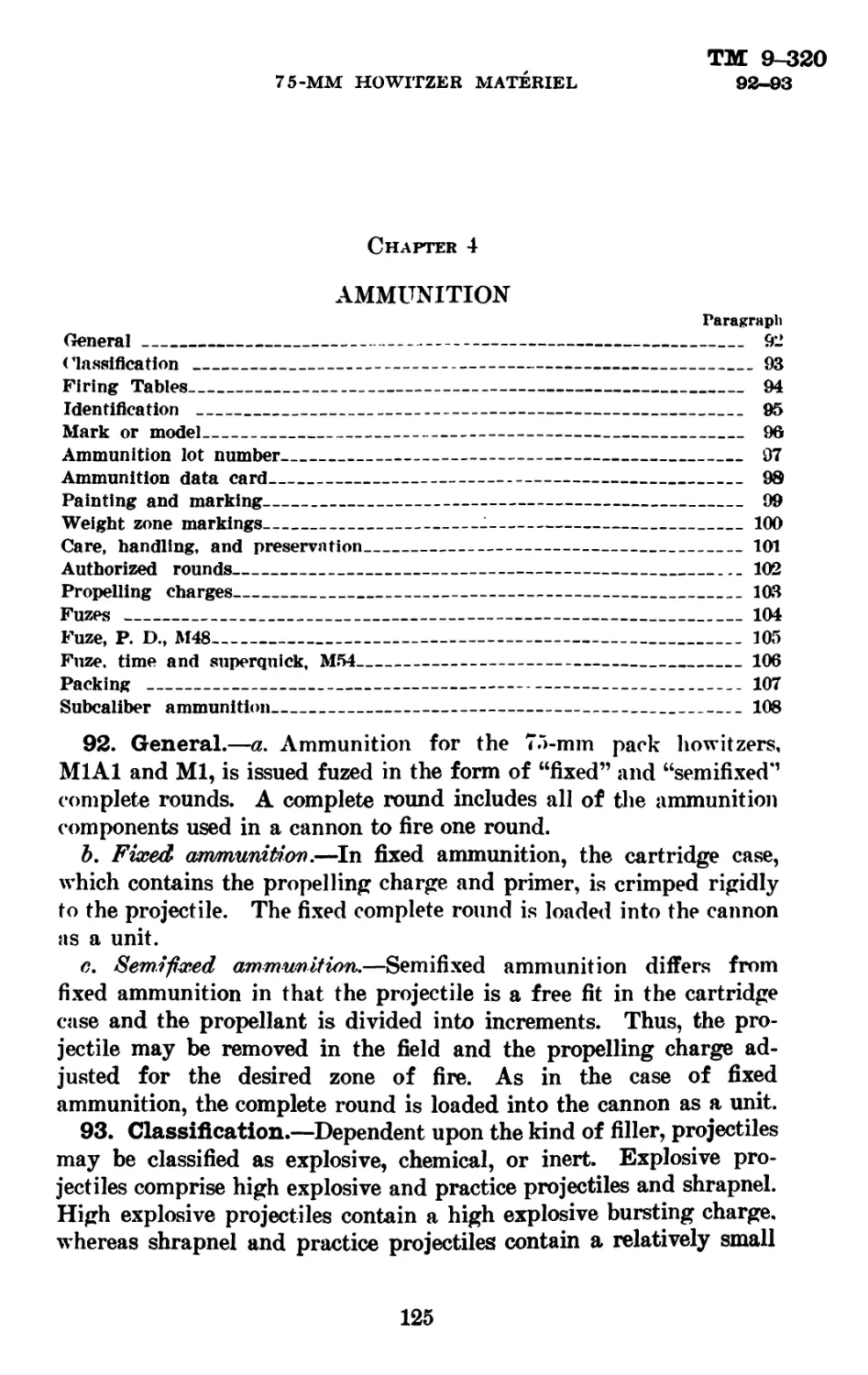
Figure 1.—Firing lock, M13, in firing position.
8
ORDNANCE DEPARTMENT
ТМ 9-320
ю
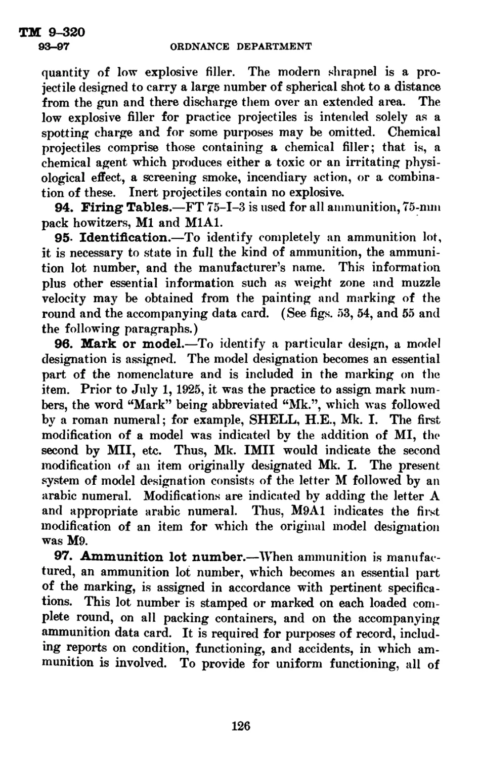
Figure 2.—Firing lock, M13, at moment of tripping the sear.
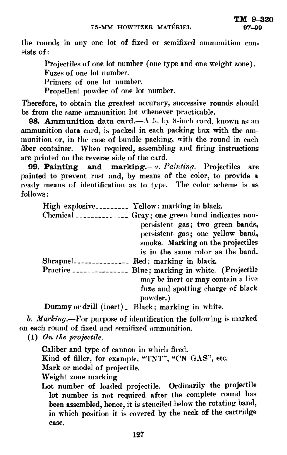
Figure 3.—Firing lock, M13, at moment of striking the primer.
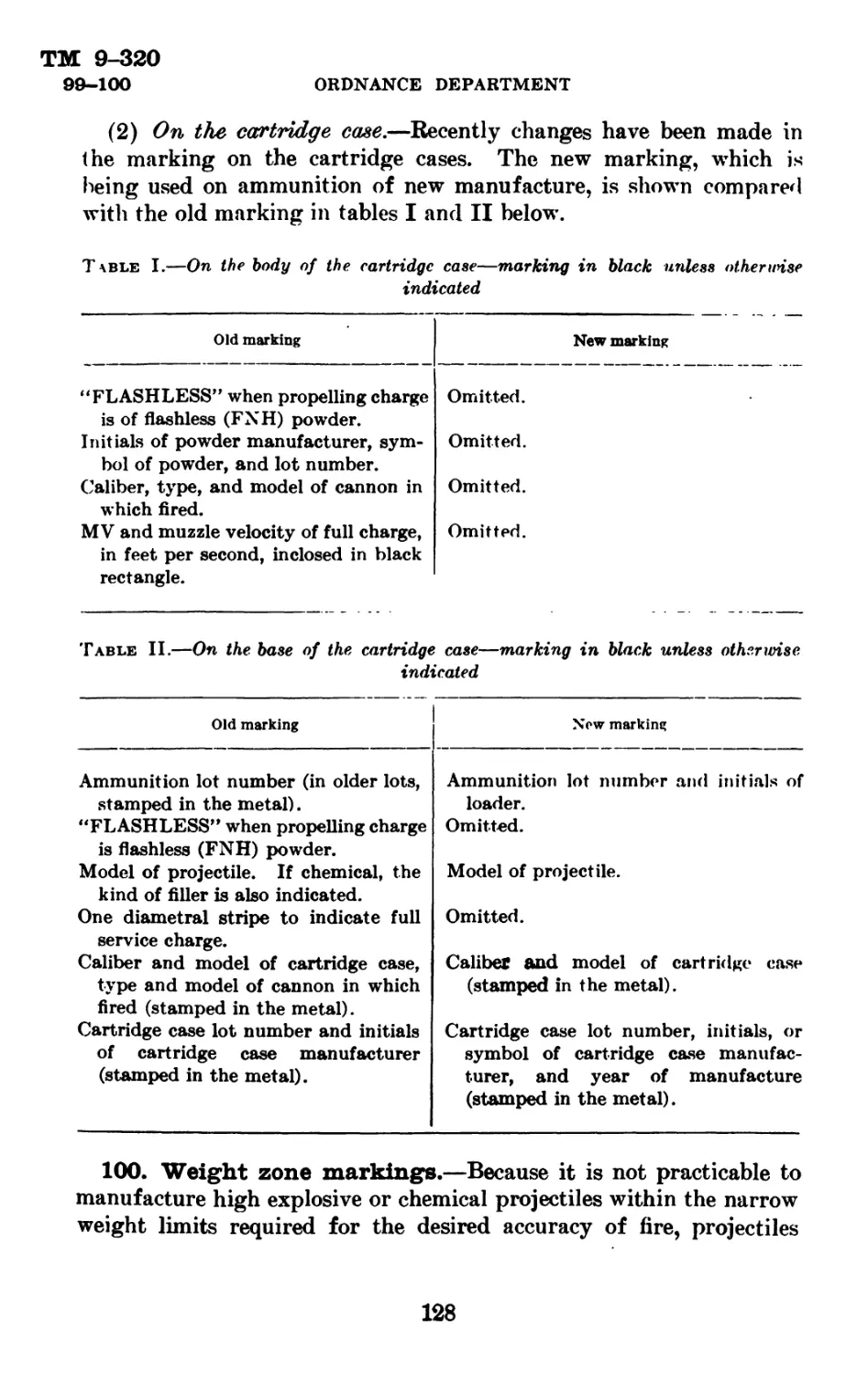
P. Trigger fork pivot.
L. Lever arm.
S. Force exerted by firing pin holder sleeve.
H. Force exerted by firing pin holder.
Figure 4.—Firing lock, M13, automatic cocking.
10
TM 9-320
11
75-MM HOWITZER MATERIEL
Section III
DESCRIPTION AND OPERATION OF 75-MM PACK
HOWITZER CARRIAGE, Ml
Paragraph
75-mm pack howitzer carriage. Ml_________________________________________ 11
Recoil mechanism--------------------------------------------------------- 12
Cradle___________________________________________________________________ 13
Equilibrators------------------------------------------------------------ 14
Rockers__________________________________________________________________ 15
Axle, traversing mechanism, and wheels----------------------------------- 16
Front trail______________________________________________________________ 17
Rear trail_______________________________________________________________ 18
Top sleigh--------------------------------------------------------------- 19
Bottom sleigh---------------------------------------------------------- 20
11. 75-mm pack howitzer carriage, Ml.—The 75-mm pack
howitzer carriage, Ml, is the standard for pack artillery. The de-
sign is for traverse on the axle. To compensate for the unbalanced
weight about the trunnions, spring equilibrators are set within
the front trails. Like the 75-mm pack howitzer this carriage may
be separated, readily and easily, into groups suitable for pack trans-
portation. The primary groups are the recoil mechanism, including
the bottom sleigh, cradle and top sleigh, front trail, rear trail, and
the wheels which are carried on the same pack load as the breech
mechanism. (See fig. 5.)
a. The elevating mechanism, rockers, and equilibrators are assem-
bled to the front trail and are carried in pack as a unit. The axle
brackets, into which the detachable axle and traversing mechanism
are assembled, are built into the front trail for two positions of the
axle. In the first or firing position the axle is well forward where
the weight of the axle and wheels is advantageously placed to in-
crease the firing stability of the carriage. The second position is
that arranged for towing when the weight of the entire materiel
is nearly balanced over the axle. In the second position the axle
rests in rear axle bearings.
Ъ. In the arrangement for towing, the axle is moved from its bear-
ings in the front of the trail to others underneath and slightly in
rear of the trunnion bearings of the rockers. The rear trail is dis-
connected and a towing pole attached in its place. The cradle, sleigh,
and howitzer are lifted from the rockers and set back until the rear
trunnions lie in brackets just forward of the trail locking device.
The front of the cradle rests on the reinforce to the forward trail
transoms. The rear trail is placed above the top sleigh, spade end
toward the towing pole and a cincha passed about the whole com-
bination to hold it together.
11
ТМ 9-320
11—12 ORDNANCE DEPARTMENT
c. During movements by rail, water, or truck, the materiel should
be arranged as prescribed in Ъ above and lashed together. This ar-
rangement takes the weight off the elevating mechanism and reduces
the possibility of damage.
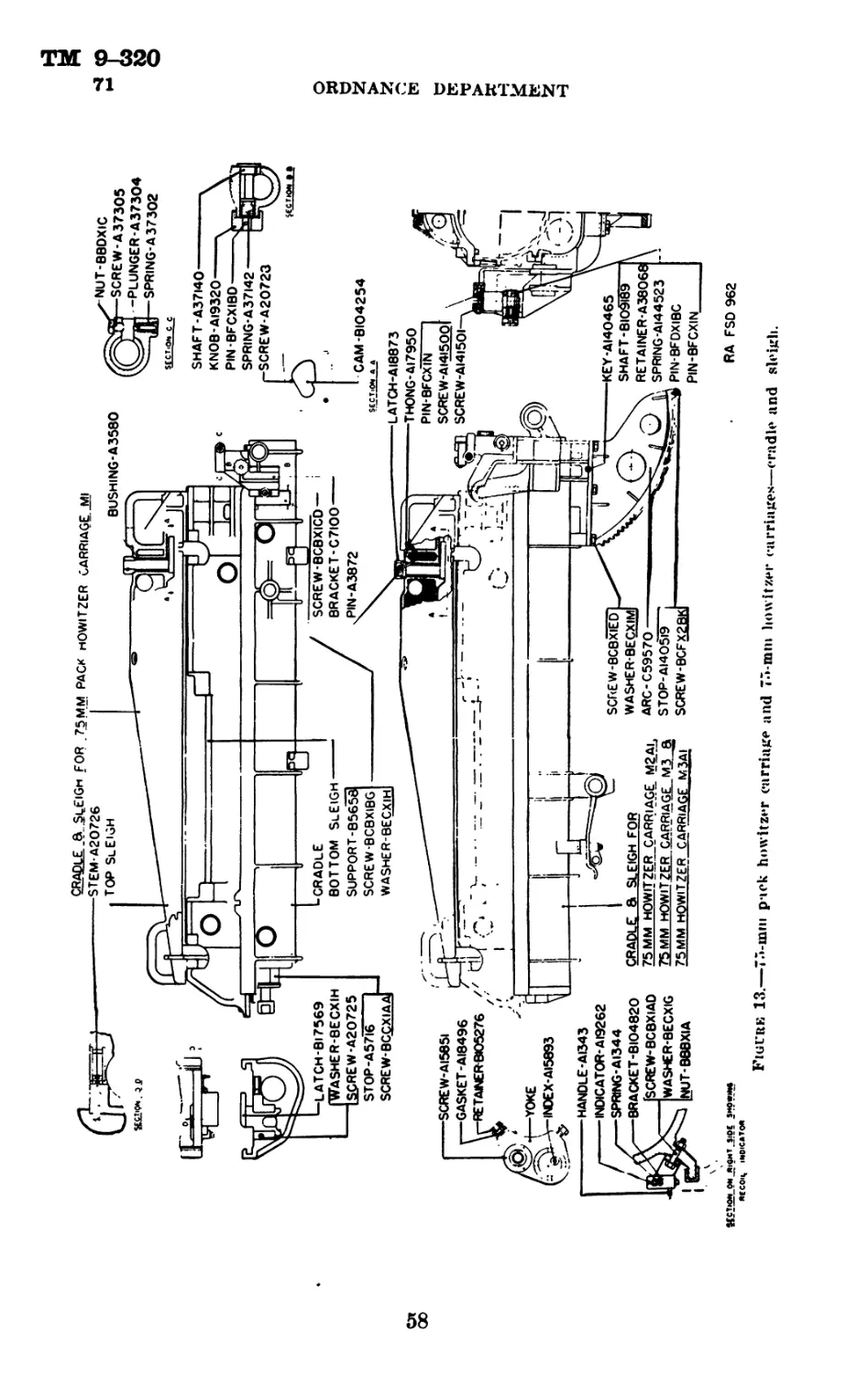
12. Recoil mechanism.—a. When the howitzer is fired, the force
which propels the projectile forward reacts upon the howitzer and
drives it to the rear. It is necessary to check this force in a gradual
manner so as not to cause displacement of the carriage. Also, the
howitzer must be brought back into battery position before it can be
fired again. These objects are accomplished by the recoil mechanism
which is of the hydropneumatic type. It combines the recoil and
counterrecoil systems housed within separate cylinders. The two
cylinders, known respectively as the recoil cylinder and the recupera-
tor cylinder, are fixed underneath the bottom sleigh and are screwed
into the yoke. The piston rod is secured to the cradle by means of
the piston rod latch. The yoke and cylinders move with the bottom
sleigh and howitzer while the piston rod remains stationary. On
each side of the bottom sleigh there are strips or slides which engage
the slideways of the cradle which guide the sleigh in recoil and
counterrecoil.
Ъ. Oil index.—The recuperator cylinder front head is fitted with an
oil index. The function of the oil index is to show the amount of
reserve oil in the mechanism. Should the howitzer he fired with the
oil index, A15893 (fig. 13), indicating a loss of oil in the system,
considerable additional stress may occur in the recoil mechanism and
cause damage. It is therefore necessary to force in enough reserve oil
to move the oil index until it is flush with the extension on the oil index
follower assembled in the recuperator cylinder front head, C5803.
c. (1) The recoil cylinder filling valve, Al9763. is contained in the
recoil cylinder filling valve housing, B105275. This valve is opened
by means of the oil extractor when it is necessary to remove reserve
oil, or by the oil screw filler when it is necessary to replenish recoil
oil which may have leaked through the recoil piston stuffing box or
through the oil index packing. It may also be necessary to replace the
oil withdrawn from the system due to expansion of the oil caused by
firing.
(2) The recoil cylinder is closed at the rear by the recoil cylinder
rear head. As this head is on the low pressure side of the piston,
elaborate packing is not required. In order to relieve the accumu-
lation of oil that may pass the piston, a relief opening is provided
in the cylinder head through which the oil may be ejected. Closing
the relief opening is a ^-inch hexagon head cap screw which pre-
12
ТМ 9-320
75-MM HOWITZER MATERIEL 12-16
vents the recoil cylinder (rear head) lock from becoming loosened,
and prevents dirt from being sucked into the cylinder. The leaking
oil may be released by removing the cap screw on the rear head.
13. Cradle.—The slides on the bottom sleigh are fitted to the ways
on the cradle. The piston rod latch, B17569, slides vertically in ways
in the front end of the cradle. When dropped behind the piston
rod nut it secures the piston rod to the cradle, and, with the bottom
sleigh and the howitzer in the cradle, it cannot be disengaged, as
interference with the howitzer tube prevents the latch from rising.
An automatic piston rod latch stem, A20726, is provided for holding
the piston rod latch in either the open or locked position. The sight
brackets are fitted with a sight retaining shaft, A37140, which is
automatically returned to the locked position. A spring-controlled
plunger, A37304, is provided to hold a lug of the telescope mount
against headless screw, A37305, which may be adjusted by means of
nut, BBDX1C. Accuracy of alinement of the sight in azimuth is
thereby maintained and quick removal of the telescope mount is pro-
vided for. (See fig. 13.)
14. Equilibrators (fig. 16).—Two equilibrators are provided to
overcome the preponderance of weight resulting from the position of
the rocker trunnions so far to the rear of the center of gravity of the
tipping parts. The equilibrator is composed of the barrel, В19613;
stem, B19614; equilibrator helical spring, A21723; equilibrator stem
plug, A21725; equilibrator pin lock, A3552; and screw, BCNX2AA,
for fastening the lock in place. The equilibrator pressure is ad-
justable within limits to secure the lightest and most uniform resist-
ance to elevation and depression. The rear end of the barrel and the
plug are adapted to receive the equilibrator locking tool to hold the
equilibrator compressed while it is being inserted or dismounted. The
load on the spring when the locking tool is inserted is approximately
1,400 pounds.
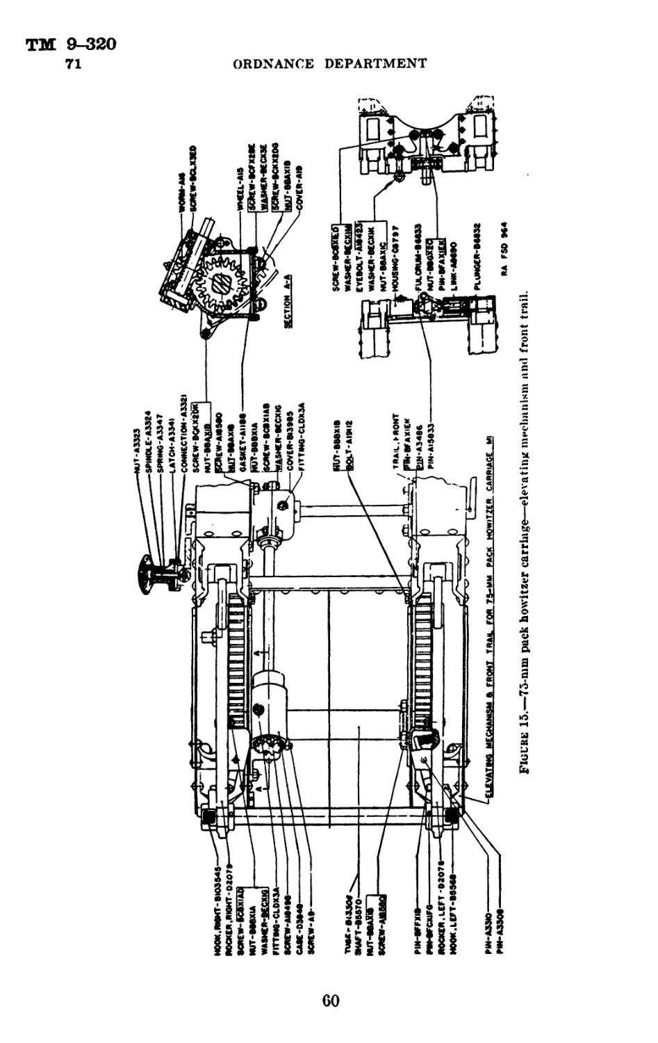
15. Rockers.—The rockers are segments of internal gears, located
on either side of the cradle in the space between inner and outer
flasks of the front trail side elements. The rockers pivot on trunnion
pins, A3486. (See fig. 15.)
16. Axle, traversing mechanism, and wheels.—a. The axle
is fitted with left and right axle arms. The left arm, C1695, is pinned,
whereas the right arm, C6586, is attached with a screw, A20723, for
disassembling purposes. The axle is grooved to form an inner race
for the traversing mechanism bearing balls. (See figs. 17 and 18.)
&. The axle is retained in its bearings in the trail by means of a
sleeve. The sleeve may be inserted by matching the proper surfaces.
13
TM 9-320
16-17 ORDNANCE DEPARTMENT
After assembling it may be locked by turning 90°, by means of the
hinged handle lock, A3363, which, when released, becomes a lever
oy which the sleeve may be turned. The body of the axle is grad-
uated in mils for traverse, the right end of the sleeve forming the
index of the graduations.
c. The traversing mechanism is composed of the traversing nut,
C8018; handwheel, C8019; machine screw, BCKX2CG; ball bearing,
CAAX1AU; ball bearing cap, B13968: ball bearing nut, A15810; and
seventy-one %e-inch steel balls. CCAX1D. The dust cover, C1666,
is provided to prevent the entry of dirt or foreign matter into the
mechanism. When the materiel is transported on its wheels the
handwheel is locked to the trail to prevent it from turning and
running the axle off center.
d. The wheels (fig. 5) are 29 inches in diameter, steel-tired, and
are secured to the axle arm by the linchpin, A15722 (fig. 17). A
drag link, B17678 (fig. 5), is provided on the outer end of the hub
ring.
17. Front trail.—Openings are provided at the front of each side
member of the front trail to house the rockers. (See fig. 15.) At the
front end, between the side members of the trail, the upper elevating
gear case, D3848, the rocker pinion shaft tube, B13506, and rocker
pinion shaft tube bearing are assembled. The elevating worm, A16,
and the elevating worm wheel, A15, are inclosed within the gear case.
The rocker pinion shaft, B5570, is inclosed within the rocker pinion
shaft tube. Axle bearings are provided at the front end of the trail
which retain the axle when the piece is in firing position. At the
bottom and to the rear of the trunnion bearings, two additional axle
bearings are fitted for retaining the axle when the materiel is trans-
ported by towing. Two bearings are assembled toward the rear
of the front trail in which the rear ends of the equilibrator rest, the
front ends being supported in bearing surfaces in the rockers.
Brackets on the top, toward the rear, support the cradle when ar-
ranged for towing. Trail hinges are attached to the rear end of the
trail. These hinges engage with other hinges on the rear trail
for assembling the materiel in firing position. The trail fulcrum
plungers, B6832, housed within the trail connecting mechanism hous-
ing, pass through the eyes of the hinges. The trail fulcrum plungers
are moved in and out by means of the trail fulcrum, B6833, and two
trail fulcrum links, A8690. By the use of a lifting bar, through the eye
of the fulcrum, it may be turned 90°, which engages or disengages
the plungers with the hinges. The trail connecting mechanism is
also utilized when attaching the towing pole. (See fig. 15.)
14
ТМ 9-320
75-MM HOWITZER MATERIEL 18-20
18. Rear trail.—The rear trail is similar to the front trail in con-
struction. It is fitted with a spade in order to prevent backward
movement of the carriage when the howitzer is fired. It is also pro-
vided with a socket for the purpose of maneuvering the carriage by
use of the handspike. The sponge staves are transported on the
inside of the rear trail. The axle and traversing mechanism assembly
is carried inside the trail with the right end of the axle in the bore
of the handspike socket and the left end over the rear trail front
transom. (See fig. 5.)
19. Top sleigh.—The top sleigh is composed of the top sleigh
body, top sleigh clamping cam, B104254; top sleigh clamping latch,
A18873; top sleigh clamping latch pin, A3872; cam bushing, A3580;
and a thong, A17950, for retaining the latch pin. The top sleigh
retains the howitzer in the bottom sleigh and also forms a covering
for it. The cam, hand operated by means of the socket of the hand-
spike, when turned to the locked position forces the top sleigh for-
ward. By inserting the top sleigh clamping latch pin the two
sleighs are locket together and retained in position. (See fig. 13.)
20. Bottom sleigh.—a. The bottom sleigh forms a seat for the
howitzer and maintains alinement of the tube and breech ring when
assembled.
Ъ. The recoil indicator bracket, B104820, which carries the recoil
indicator, A19262, with its spring, A1344, and handle, A1343, for
recording the length of recoil, is bolted to the right side of the bottom
sleigh near the front. The recoil indicator is a spring plunger ar-
rangement and may be set so that its point will trace a path in grease
or similar substance smeared on top of the cradle. The length of
recoil may be read on a scale cut in the cradle. When not in use
the recoil indicator is raised and retained out of contact with the
cradle by its handle resting in a notch in the wall of the bracket.
(See fig. 13.)
Section IV
DESCRIPTION AND OPERATION OF 75-MM HOWITZER
CARRIAGE, M3A1
Paragraph
75-mm howitzer carriage. M3A1____________________________________________ 21
Recoil mechanism--------------------------------------------------------- 22
Cradle___________________________________________________________________ 23
Top carriage------------------------------------------------------------- 24
Bottom carriage__________________________________________________________ 25
Elevating mechanism______________________________________________________ 26
Traversing mechanism------------------------------------------------------ 27
Equilibrators____________________________________________________________ 28
15
ТМ 9-320
21-26 ORDNANCE DEPARTMENT
Paragraph
Trails___________________________________________________________ 29
Wheels___________________________________________________________ 30
Brake mechanism-------------------------------------------------- 31
Wheel carriers--------------------------------------------------- 32
Wheel latch______________________________________________________ 33
Firing base----------------------------------------------------- 34
Firing base lock------------------------------------------------- 35
Cradle lock----------------------------------------------------- 36
21. 75-mm howitzer carriage, M3A1.—The 75-mm howitzer
carriage, M3A1, is the present standard designed especially for high
speed travel. This carriage is a split trail type vehicle having pneu-
matic tired disk and rim wheels mounted on antifriction bearings and
equipped with standard commercial automobile brakes. Spring
equilibrators support the unbalanced weight of the tipping parts
(See fig. 6.)
22. Recoil mechanism.—See paragraph 12.
23. Cradle.—The slides on the bottom sleigh are fitted to the ways
on the cradle. The piston rod latch, B17569, slides vertically in ways
in the front end of the cradle. When dropped behind the piston
rod nut it secures the piston rod to the cradle, and with the bottom
sleigh and the howitzer in the cradle it cannot be disengaged, as
interference with the howitzer tube prevents the latch from rising.
An automatic piston rod latch stem, A20726, is provided for holding
the piston rod latch in either open or locked position. (See section
D-D, fig. 13.) The sight brackets are fitted with a sight retaining
shaft, B109189, which is automatically returned to the locked posi-
tion. A sight clamping screw, A141500, is provided to hold a lug
of the telescope mount, or of the range quadrant, against a head-
less screw, A141501, which may be adjusted by loosening the nut,
BBDX1C. (See section C-C, fig. 13.) Accuracy of alinement of
the sight in azimuth is thereby maintained and quick removal of
the telescope mount is provided for.
24. Top carriage.—The top carriage has trunnion bearings at the
top which support the cradle and cup-shaped bearings at the bottom
to support the lower ends of the equilibrators. The elevating gear
case and pads, for attaching the traversing and elevating handwheel
shaft brackets, are fitted to the top carriage. (See fig. 10.)
25. Bottom carriage.—The bottom carriage is fitted with a pintle
bearing, trail brackets, trail lock pin bracket, firing base hinge
brackets, stops to locate the traveling lock in traveling position and
a traversing rack. (See fig. 10.)
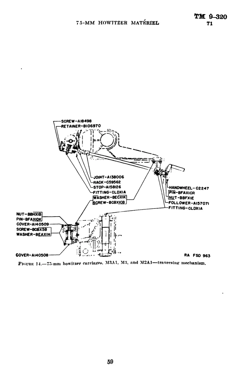
26. Elevating mechanism.—The tipping parts may be elevated
or depressed by means of the elevating handwheel, C2247, located
16
TM 9-320
75-MM HOWITZER MATERIEL 26-31
on the right side of the carriage. Stops are provided at each end
of the elevating arc, C59570, which regulate maximum elevation and
depression. The rotating parts are mounted on oil-sealed antifric-
tion bearings. (See figs. 9, 13, and 24.)
27. Traversing mechanism.—The carriage may be traversed in
the desired direction by means of the traversing handwheel, C2247,
located on the left side of the carriage. Stops are provided at each
end of the traversing rack, C59562, to regulate maximum traverse.
The rotating parts are mounted on oil-sealed antifriction bearings.
(See figs. 9 and 14.)
28. Equilibrators.—Two equilibrators are provided to overcome
the preponderance of weight resulting from the position of the rocker
trunnions so far to the rear of the center of gravity of the tipping
parts. The high speed howitzer equilibrator is composed of the
equilibrator spring, A136543; equilibrator barrel, B108630; equili-
brator cylinder assembly, and equilibrator trunnion pin lock, A3552.
Adjustment of the spring trunnion is obtained by adjusting the equil-
ibrator trunnion pins. The equilibrators for carriage, M3A1, are
equipped with the bent pin, A158054. (See fig. 10.)
29. Trails.—When spread to their full open position the trails are
locked by means of the trail lock pins, A157690. The pins are in-
serted in the trail lock pin brackets of the trail and through mating
holes in the trail lock pin brackets on the bottom carriage. When
the trails are closed to their traveling position they are locked
together by means of a toggle type mechanism. In the operation
of locking the trails together the trail lock hook, A18962, which
is connected to the trail lock lever, A18960, on the right trail, is
inserted into the trail lock loop, A157023, assembled to the left
trail. When the trail lock lever is pressed down it draws the two
trails together tightly, and by inserting a cotter pin through the trail
lock lever and the trail connection bracket they are locked in travel-
ing position. (See fig. 9.)
30. Wheels.—Each wheel consists of disk and rim, pneumatic
truck-bus balloon tire, puncture-sealing or bullet-sealing inner tube,
and a tire locking ring. (See fig. 19.)
31. Brake mechanism.—The brake mechanism for the 75-mm
howitzer carriage, M3A1, is the internal expanding type. The brake
shoes, C62667, actuated by the hand brake lever, B150601, are attached
to the brake cam shaft, B150584. Movement of the brake lever forces
the brake cam, В144968, against the brake cam rollers, В144955, of
the brake shoes causing them to expand against the brake drums
which are rigidly attached to the wheels. When the brake lever is
319275°—11----2
17
ТМ 9-320
31-35 ORDNANCE DEPARTMENT
placed in the “off” position the brake shoes are forced toward the
center of the wheel by means of the brake shoe retracting spring,
B144956 and B144957. (See fig. 21.)
a. Movement of the hand brake lever, B150601, is controlled by the
brake ratchet pawl engaging teeth of the brake ratchet rack, B150685.
Ъ. The brake shoes may be adjusted for wear by means of the brake
adjusting wedge.
32. Wheel carriers.—The wheel carriers for the carriage, M3A1,
are designed to facilitate changing the carriage from the firing to
traveling, or from traveling to firing positions. They are assembled
to the bottom carriage by wheel carrier pins. Bronze washers,
A140573, and slotted nuts are assembled on the wheel carrier pins to
retain the wheel carrier to the bottom carriage with just enough
tension to allow a revolving movement of the wheel carrier without
undue end play. The wheel spindle. B144817, assembled to the wheel
carrier, is retained in a rigid position by means of tapered surfaces
on the shank and secured by a washer and slotted nut assembled to
the wheel spindle. (See fig. 21.)
33. Wheel latch.—The wheel latch mechanism secures the wheel
carriers in traveling and firing positions. To release the wheel car-
rier press down on the wheel latch plunger, A161606 (A157080 for
carriages M2A1 and М3). The wheel latch lever actuates the wheel
latch bolt, A161602 (A140408 for carriages M2A1 and М3), which
engages mating holes in the spring carriers and wheel carriers when
in either traveling or firing position. The movement of the wheel
latch bolt is controlled by slots cut on the side of the wheel carrier
brackets. (See fig. 21.)
34. Firing base.—The firing base, pertaining to the 75-mm how-
itzer carriage, M3A1, is designed to combine the functions of the
firing base and traveling lock. When traveling the firing base is
swung up until the slotted bearing of the base engages the cradle
lock pin, B108609, and is secured by turning the cradle lock pin
handle, B13942. parallel with the cradle. (See fig. 6.)
35. Firing base lock.—The firing base lock of the 75-mm how-
itzer carriage, M3A1, consists of a firing base lock plunger, B144943,
actuated downward by a compression spring and withdrawn by de-
pressing the firing base lock pedal. The plunger is retained in a
housing on the bottom carriage. The firing base lock spring retainer,
A157735, which is screwed into the upper end of the housing, controls
the motion of the upper end of the plunger. The lower end of the
plunger is enlarged to fit the inside of the opening in the firing base
and to retain the compression spring at its lower end. When the
18
ТМ 9-320
75-MM HOWITZER MATERIEL 35-37
firing base is dropped into firing position the compression spring au-
tomatically actuates the plunger locking the firing base. (See fig. 7.)
36. Cradle lock.—The cradle lock consists of a cylindrical pin,
B108609, flattened on two sides and rotated by the cradle lock pin
handle which in turn is secured to the cradle by means of a turn-
buckle. When the cradle lock pin handle, B13942, is in a vertical
position it allows the traveling lock to be seated. Turning the cradle
lock pin handle to a horizontal position locks the traveling lock to
the cradle. (See fig. 6.)
Section V
DESCRIPTION AND OPERATION OF 75-MM HOWITZER
CARRIAGES, М3 AND M2A1
Paragraph
General__________________________________________________________________ 37
Brakes_________________________________________________________________ 38
Spring carriers-------------------------------------------------------- 39
Firing base---------------------------------- _ ------------------------- 40
Firing base lock_______________________________________________________ 41
Traveling lock------------------------------------------------------- 42
Equilibrators------------------------------------------------------------ 43
37. General.—The 75-mm howitzer carriages, М3 and M2A1, have
the same general appearance as the M3A1 carriage. The major dif-
ferences in construction are as follows:
a. The М3 carriages have spring carriers at the present time,
whereas the M2A1 and M3A1 models have springless carriers. How-
ever, changes are to be made on all of the М3 carriages which will
embody replacement of the spring carriers by the M3A1 type
springless wheel carriers.
b. The М3 and M2A1 carriages have a traveling lock, whereas on
the M3A1 carriage this function is performed by the firing base when
in traveling position.
c. The М3 carriages have external brake mechanisms while the
M3A1 and M2A1 carriages have the internal type. However, it is
contemplated that the present external brakes on the М3 carriages
are to be replaced by the internal type.
d. The position of the cradle lock pin hole of the М3 Al carriage
is changed.
e. The shape of the trails is changed, and the lunette of the М3
carriage is placed on the left trail while that of the M3A1 carriage
is attached to the right trail.
/. The equilibrator trunnion pins are changed according to
paragraph 43.
19
TM 9-320
38-42 ORDNANCE DEPARTMENT
38. Brakes.—The brake band is actuated by means of a brake
lever, C59579, hinged to the carriers, D7291 and D7304, by the brake
shafts, B108597 and B108598. Movement of the brake lever causes
the brake band to hug the brake drum, creating enough friction to
bring the vehicle to a stop. The brake band may be adjusted by
means of the brake band adjusting nut, A137462, and equalized by
means of the fillister head screw, A137598, in the guide. (See
fig. 20.)
39. Spring carriers.—a. The spring carriers of the 75-mm how-
itzer carriage, М3, are designed to absorb the road shocks in con-
junction with the pneumatic tired wheels and thereby improve the
riding qualities of the carriage. (See fig. 20.)
6. The spring carrier bracket is a steel casting containing two
bored cylinders. Each cylinder contains a helical spring, A140597;
spring carrier shaft upper bushing, A140586; and spring buffer,
A140584. The top of each cylinder is closed by means of a bracket
buffer cap screwed to it and retained in position by means of a set
screw, BCTX1BF. Spring carrier shafts, B108606, are assembled
through the cylinder and attached to the wheel carrier by nuts at
each end of the shaft.
40. Firing base.—The firing base pertaining to the 75-mm how-
itzer carriages, М3 and M2A1, is designed to support the weight of
the carriage when in firing position. The base swings on pins which
connect the firing base to the bottom carriage. When traveling, the
base is swung upward and is locked to the traveling lock by the
spring actuated lock plunger, B144334. (See fig. 10.)
41. Firing base lock.—The firing base lock pertaining to the
75-mm howitzer carriages, М3 and M2A1, is assembled near the bot-
tom of the front of the bottom carriage. The mechanism is com-
posed of the two spring actuated latches actuated by a toggle action
which is operated by the firing base lock release. The release,
B108619, is operated by the foot and when pressed down will disen-
gage the latches and permit the firing base to be swung into traveling
position. The latches return to their engaged position by the tension
of the springs and will automatically latch the firing base when
dropped into firing position. (See fig. 11.)
42. Traveling lock.—The traveling lock of the 75-mm howitzer
carriages, М3 and M2A1, supports the cradle and firing base when
in traveling position. The traveling lock is hinged to the bottom
carriage and when in traveling position it is locked to the cradle
by means of the cradle lock pin, B108609. In firing position the
traveling lock is disengaged from the cradle and lowered until the
20
ТМ 9-320
75-MM HOWITZER MATERIEL 42-45
stop at the bottom of each leg comes in contact with the bottom
carriage. (See fig. 10.)
43. Equilibrators.—The equilibrators for the М3 and M2A1 car-
riages are identical with those on the M3A1 carriage except that
the equilibrator on the left side of the carriage is equipped with a
straight equilibrator trunnion pin, A21724, (fig. 16), whereas the
equilibrator on the right side has a bent pin.
Section VI
DISASSEMBLY AND ASSEMBLY
Paragraph
General------------------------------------------------------- 44
Disassembly of breech mechanism--------------------------------45
Assembly of breech mechanism---------------------------------- 46
Recoil mechanism---------------------------------------------- 47
Disassembly and assembly of 75-mm pack howitzer carriage, Ml__ 48
Disassembly and assembly of 75-mm howitzer carnages, M3A1, М3,
and M2A1____________________________________________________ 49
44. General.—a. Incidents of wear, breakage, cleaning, and in-
specting make necessary the occasional disassembly of various parts
of the howitzer and carriage. This work comes under two head-
ings—that which can be performed by the battery personnel, and
that which must be performed by ordnance personnel.
6. The battery personnel may, in general, do such dismounting as
is required for the assembly of parts indicated in Standard Nomen-
clature Lists Nos. C-20, C-26, and C-29. Such work should be done
in the manner prescribed. Any difficulty which cannot be overcome
must be brought to the attention of ordnance personnel.
c. The battery personnel will not attempt to disassemble any part
of the recoil mechanism not authorized nor do any filing on the
sights or howitzer parts other than outlined and only by order of
the battery commander.
d. The use of wrenches which do not fit snugly on any parts
should be avoided. They will only fail and will damage the corners
of nuts and bolt heads.
e. When assembling, the assembly of subassemblies should be com-
pleted before attempting to assemble the larger assemblies in which
the subassemblies are placed. In all assemblies the bearings, slide
surfaces, threads, etc., should be cleaned and lubricated.
45. Disassembly of breech mechanism.—a. (1) Open the
breech to the point where the assembling line on the top of the operat-
ing lever is parallel with the side of the breech ring and lift out the
operating lever pivot, B8029. (See fig. 12.)
21
ТМ 9-320
45-46
ORDNANCE DEPARTMENT
(2) Slide the breechblock out to the right far enough to clear the
crosshead, A12124, and lift off the operating lever.
(3) Take the breechblock out to the right. This will leave the ex-
tractor, B8027, free, and it may be removed. Prior to removing the
breechblock of the field howitzer, the breech ring must be removed
from the bottom sleigh.
(4) The breechblock bushing, A21299, will not be removed.
(5) Lay the breechblock on its rear face.
(6) Slide out the gear cover, A12131, pull out the trigger, start
the trigger shaft, A12138, by engaging a screw driver or the knob
of the trigger shaft in the partial annular slot in the trigger shaft
gear, and pull out the trigger shaft.
(7) Turn the breechblock up. Rotate the firing case 60° in either
direction and pull it out of the breechblock.
Ъ. Firing lock.—(1) Pry the trigger fork, A12132, out of the firing
case, C3537, with a screw driver, first through the trigger shaft hole,
then from the outside of the case. (See fig. 12.)
(2) Insert the trigger shaft to engage one of the yoke ends of the
sear. Press the front end of the sear out of engagement with the
firing pin holder, B8187, insert a screw driver in rear of the firing pin
holder sleeve, A12133, and pry the sleeve and holder forward until
they can be grasped by the fingers and pulled from the case.
(3) Remove the trigger shaft and draw out the sear, B8031, and
sear spring, A12135.
(4) Hold the front end of the firing pin holder, B8187, in one hand
and place the rear end of the sleeve against the edge of a bench or
some convenient part of the carriage. Push against the front end of
the firing pin holder to compress the spring and press the rear end
of the holder down to unhook it from the rear end of the sleeve.
Allow the holder to recede out of the sleeve, freeing the spring.
(5) Remove the cotter pin, unscrew the firing pin bushing, A12579,
and push the firing pin, A12755, out of the bushing.
c. Operating lever.—Press the operating lever latch, A12125, into
the operating lever until they are parallel. This alines the keyways
in the two pieces. Push the operating lever latch pivot, A12127, out
and remove the latch and spring, A12128. Drive out the crosshead
pin, A12126, and remove the crosshead, A12124. (See fig. 12.)
46. Assembly of breech mechanism.—a. Operating lever.—
Assemble the crosshead, A12124, on the stud of the operating lever
and drive in the crosshead pin. Place the latch spring in the handle of
the lever. Put the latch in position with the stud on the latch into
the spring and press in on the latch to the point where the pivot holes
and keyways are in alinement and insert the pivot. (See fig. 12.)
22
TM 9-320
46
75-MM HOWITZER MATERIEL
b. Firing lock.—(1) Insert the firing pin, A12755, into the firing
pin bushing and screw the bushing into the firing pin holder. Put
in the cotter pin and spread the ends so that they will not rub the
firing case.
(2) Assemble the firing spring over the firing pin holder and the
firing pin holder sleeve over the spring and holder. Force the
sleeve against the spring, compressing the spring to allow the bev-
eled surfaces on the sleeve and holder to hook together. This can
be accomplished by grasping the holder with one hand and guiding
the sleeve with the other while pushing the rear end of the sleeve
against the edge of a bench or convenient part of the carriage to
compress the spring.
(3) Insert the sear spring into its seat in the bottom of the firing
case, using a screw driver between two coils of the spring for the
purpose. Assemble the sear into the case, locating the stud into the
sear spring. Press the sear down against the spring with the fingers
and insert the trigger shaft temporarily into the firing case and
through the sear.
(4) Using a small screw driver press the sear down and insert the
assembled firing pin holder and sleeve into the case. Withdraw the
screw driver and push the holder fully home.
(5) Remove the trigger shaft and insert the trigger fork into the
opening in the bottom of the case with the part marked Umuzzle
face” toward the front, in which position the rounded ends of the
fork bear against the rear face of the firing pin holder sleeve. Push
the trigger fork in until it snaps into position.
c. Breech mechanism.—The breech mechanism of the pack how-
itzer may be assembled with the breech ring mounted or dismounted;
however, in the case of the field howitzer, the breech ring must be
dismounted (see fig. 7).
(1) Place the extractor, B8027, in the breech recess with its lower
trunnion resting at the forward end of the curved groove in the
breech ring.
(2) Slide the breechblock part way into the breech recess from the
right side. Leave the groove across the top of the block exposed
for entry of the crosshead attached to the operating lever.
(3) Hold the operating lever about parallel with the side of the
breech ring and place the crosshead in the groove in the breech-
block. Push the breechblock into the breech recess far enough to
aline the operating lever pivot holes in the breech ring and lever.
Move the lever to aline the keyways and insert the pivot.
(4) Close the breech. Assemble the firing lock into the breech-
block by pushing it in until the sectors on the firing case strike those
23
ТМ 9-320
46-49 ORDNANCE DEPARTMENT
in the breechblock. Push gently on the firing case, and at the same
time rotate it in either direction to match up the sectors on the case
with the spaces between the sectors in the breechblock, so that the
case slides forward until the head strikes the block. Rotate the case
until the lines on the case and the breechblock marked “TOP”
coincide.
(5) Insert the trigger shaft into the breechblock and through the
firing case. The assembly line on the gear of the trigger shaft must
match the line on the breechblock to enter the square on the trigger
shaft through the hole in the trigger fork.
(6) Assemble the trigger into the breechblock, matching the assem-
bly line with a similar line on the trigger shaft.
(7) Open the breech and push the gear cover down in the breech-
block to retain the trigger shaft and trigger.
47. Recoil mechanism.—The recoil mechanism is a complicated
mechanism and not suited for successful disassembling except at an
arsenal or shop equipped for the work. The high pressure present
in the system at all times makes it extremely dangerous to attempt
unauthorized disassembly. It is, therefore, forbidden to perform any
disassembling of the inside parts of the recoil mechanism. In order
to relieve the accumulation of oil that may pass the recoil piston,
the cap screw and spring lock in the recoil cylinder rear head may
be removed and the piece elevated until the oil drains off.
48. Disassembly and assembly of 75-mm pack howitzer
carriage, Ml.—In general, no disassembling of the carriage will be
undertaken by the battery personnel other than into the various
pack loads. Certain complete assemblies and minor individual parts
may be removed and replaced if necessary. These are all indicated
in Standard Nomenclature List No. C-20. (See appendix.)
49. Disassembly and assembly of 75-mm howitzer car-
riages, M3A1, М3, and M2A1.—a. Dismounting top and bottom
sleighs, howitzer tube, and breech ring.—(1) To disengage the top
sleigh, pull the top sleigh clamping latch pin, A3872, from the top
sleigh clamping latch, A18873, and turn the latch one-quarter of a
turn. Move the top sleigh to the rear, disengaging it from the
lugs on the bottom sleigh, and lift it off. (See fig. 13.)
(2) To disengage the howitzer from the bottom sleigh, insert a
trail handspike in the forward lifting eye of the howitzer tube, turn
the tube until the eye is vertical, and force the tube forward until
it is free of the breech ring. Two men, one at either end of the tube,
may then lift the tube clear of the bottom sleigh by grasping a lifting
eye with one hand and inserting the other hand in the bore.
24
ТМ 9-320
75-MM HOWITZER MATERIEL 49-50
(3) Two men may then lift the breech ring straight upward until
it is free of the bottom sleigh.
(4) To remove the bottom sleigh, disengage the piston rod latch,
B17569, and push the sleigh to the rear and free of the cradle by
using two pairs of men at opposite ends of the bottom sleigh.
&. Assembling the top and bottom sleighs, howitzer tube, and
breech ring.—To mount the bottom sleigh, breech ring, tube, and top
sleigh, reverse the order of procedure as outlined in a above.
c. Disassembly of equilibrator group from carriage.—To remove
equilibrator group assembly from the carriage the procedure is as
follows (see fig. 10) :
(1) Elevate the howitzer to zero elevation.
(2) Insert the equilibrator assembling bolt, A140673 (an acces-
sory), through the opening in the cup-shaped bearing of the bottom
carriage and through the barrel, B108630. Advance the bolt until
it comes in contact with the equilibrator spring guide tube plug,
A140626; screw it into the plug as far as it will go.
(3) Elevate the howitzer to its maximum elevation and remove
the equilibrator group assembly.
d. Assembly of equilibrator group.—The mounting the equili-
brator group assembly is the reverse order of dismounting.
e. General.—Except for necessary disassembly operations in the
care and preservation of the materiel as given in section X and the
replacement of parts as authorized in Standard Nomenclature List
No. C-26, the battery personnel will not undertake further disassembly
of the carriage.
Section VII
PROCEDURE TO PLACE MATERIEL IN FIRING AND
TRAVELING POSITIONS
Paragraph
Operation in dismounting materiel for pack_________________________________ 50
Operation in mounting materiel for firing__________________________________ 51
To change M3A1 carriage from traveling position to firing position--------- 52
To change M3A1 carriage from firing position to traveling position--------- 53
To change М3 and M2A1 carriages from traveling position to firing
position------------------------------------------------------------------ 54
To change М3 and M2A1 carriages from firing position to traveling
position__________________________________________________________________ 55
50. Operation in dismounting materiel for pack.—a. Gen-
eral,.—Four men, equipped with two lifting bars, are required.
The carriage must be in firing position with the cradle level and
with telescope mount removed.
25
TM 9-320
50-51
ORDNANCE DEPARTMENT
Ъ. To disengage top sleigh.—Pull the top sleigh clamping latch
pin, A3872, from the top sleigh clamping latch, A18873, and apply
the socket of the handspike to the top sleigh clamping latch and
turn it one quarter of a turn. Move the top sleigh to the rear, dis-
engaging it from the hooks or lugs on the bottom sleigh. Thrust
a lifting bar through the 1^-inch hole in the top sleigh and lift
it off. Lay the top sleigh to one side until the cradle is dismounted.
(See fig. 13.)
c. Insert a lifting bar in the forward lifting eye of the howitzer
tube, turn the howitzer until the eye is vertical and pass the lifting
bar through the lifting eye. Two men grasping the bar, force the
tube forward free of the breech. When free, pass a second lifting
bar through the eyebolt on the rear and place the tube on the pack.
Put on and adjust the tube and muzzle covers.
d. Insert a lifting bar through the eyebolt on the breech ring.
The breech ring is lifted off. The breech ring cover is put on and
the breech ring placed on the pack.
e. Disengage the piston rod latch, B17569, and start the bottom
sleigh to the rear, passing a lifting bar through the rear bar holes.
When the forward lifting bar opening passes the wheels, insert a
lifting bar. Slide the bottom sleigh out, turn it upside down, and
place it on the pack. (See fig. 13.)
/. Place the top sleigh upside down in the cradle. Disengage the
trunnion hooks, right and left, B103545 and B5568. Insert the front
lifting bar. Lift the front end of the cradle until the rear lifting
bar can be inserted. Remove the cradle and top sleigh and assemble
the combination to the pack. (See fig. 15.)
g. Ta dismount the trail.—(1) Insert a lifting bar through the
eye of the fulcrum and turn it in a horizontal arc to the right and
withdraw the bar. Supporting the trail on both sides, raise the
center until the joint is broken and then allow the trails to rest on
the ground. The rear trail is turned upside down and placed on
the pack.
(2) The axle sleeve lock, A3363, is disengaged and the axle sleeve
revolved to the position of disengagement. The front end of the
front trail is supported while the wheels and axle are run out. The
front trail is mounted on the pack. (See fig. 17.)
h. The axle is supported and the wheels removed. The wheels are
mounted on the pack carrying the breech ring; the axle is mounted
on the rear trail pack.
51. Operation in mounting mat£riel for firing.—To mount
the materiel for firing, reverse the order of procedure as outlined
for the operation in dismounting the materiel for pack.
26
TM 9-320
52-54
75-MM HOWITZER MATERIEL
52. To change M3A1 carriage from traveling position to
firing position.—Proceed as follows:
a. Dismount the sighting equipment chest from the trails. Release
the trail lock lever, A18960 (fig. 9). Spread the trails to approxi-
mately a parallel position.
b. Release the cradle lock pin, B108609, and lower the firing base
until it is latched by the firing base lock plunger, В144943. (See
figs. 6 and 7.)
e. Place the handspikes in the socket of the wheel carriers and
relieve the weight on the wheel latch bolt, A161602. Push down
on the wheel latch plunger, A161606. then withdraw the wheel latch
bolt. Lower the carriage by revolving the wheel carriers until the
firing base rests on the ground. (See fig. 21.) Spread the trails
to their open position and insert the trail lock pins, A157690. (See
fig. 9.)
53. To change M3A1 carriage from firing position to travel-
ing position.—Proceed as follows:
a. Withdraw the trail lock pins, A157690. Close the trails to
approximately a parallel position by means of the handspikes in-
serted in the trail handspike sockets. Release the hand brake levers.
b. Push down on the wheel latch plungers, A161606 (fig. 21),
rotate the wheel carriers and wheels by means of the handspikes
placed in the wheel carrier handspike socket toward the rear until
the wheel carriers come in contact with wheel latch stops, A140327
(fig. 7), then engage the wheel latch bolts.
c. Release the firing base lock by stepping on the pedal. Swing
the firing base up and secure it to the cradle by means of the cradle
lock pin, B108609. (See fig. 6.)
d. Close the trails and lock them together by the trail locking
mechanism. Mount the sighting equipment chest on the trails.
54. To change М3 and M2A1 carriages from traveling posi-
tion to firing position.—Proceed as follows:
a. Dismount the sighting equipment chest from the trails. Re-
lease the trail lock lever, A18960 (fig. 8). Spread the trails to ap-
proximately a parallel position.
b. Release the spring actuated latch plunger, B144334, and lower
the firing base into position. Disconnect the traveling lock from
the cradle. (See fig. 10.)
c. Place the handspike in the socket of the wheel carrier and
release the weight on the wheel latch bolt, A140408. Release the
wheel latch, A140326, and withdraw the wheel latch bolt, A140408.
Lower the carriage by revolving the wheel carriers until the firing
base rests on the ground. (See figs. 20 and 21.) Spread the trails
27
TM 9-320
54-56 ORDNANCE DEPARTMENT
to their open position and insert the trail lock pins, A155843. (See
fig. 8.)
55. To change М3 and M2A1 carriages from firing position
to traveling position.—Proceed as follows:
a. Withdraw the trail lock pins, A155843. Close the trails to
approximately a parallel position by means of the trail handspikes.
Release the hand brake levers.
b. Release the wheel latches, A140326 (fig. 21), rotate the wheel
carriers and wheels by means of the handspike toward the rear
until the wheel carriers come in contact with wheel latch stops,
A140327 (fig. 7), and then engage the wheel latch bolts, A140408
(fig. 21).
c. Connect the traveling lock and secure it to the cradle by means
of the cradle lock pin, B108609. Release the firing base lock by
stepping on the pedal of the firing base lock release, B108619, then
swing the firing base, C60298, up until it is locked to the traveling
lock by the spring actuated latch plunger, B144334. (See figs. 10
and 11.)
d. Close the trails and lock them together by the trail locking
mechanism. Mount the sighting equipment chest on the trails.
Section VIII
INSPECTION AND ADJUSTMENT
Paragraph
Inspection and adjustment_________________________________ 56
56. Inspection and adjustment.—The following instructions
should be scrupulously observed.
Parts to be inspected Points to observe
a. Thehowitzerasa a. General appearance; smoothness of
unit. operation of the breech mechanism in
opening and closing; the bore for copper
deposits on the lands and grooves; erosion
at the origin of rifling; condition of
threads on the exterior of the tube and
interior of the breech ring.
i. Breech ring. b. Condition of the eyebolt; burs or
roughness on the leveling plates.
c. Breechblock. c. Indication of burs, roughness, or
scoring.
28
TM 9-320
56
75-MM HOWITZER MATERIEL
Parts to be inspected Points to observe
d. Firing lock, M13. d. Condition of all parts; weak or broken springs; cracked or broken sear.
e. Adjustment. e. The howitzer is so designed that it requires no adjustment. If any of the parts show excessive wear they are to be replaced.
/. The carriages as units. /. General appearance. Whether the lubricating fittings are painted red and a red ring has been painted around all oil holes, and the carriages are painted in accordance with regulations.
g. Recoil mechanism. g. That the proper amount of oil is in the system. (See par. 126.) Whether the oil index functions correctly.
h. Elevating mechan- ism. Л. Whether operation is smooth and mechanism is properly lubricated. Ele- vate and depress, and note whether the equilibrators and all rockers are per- forming their functions properly. Turn the handwheel back and forth, and note the amount of backlash. If it exceeds one-quarter turn of the handwheel notify the ordnance personnel.
i. Traversing mechan- ism. i. Whether operation is smooth and the parts properly lubricated. Turn the handwheel back and forth, and note the amount of backlash. If it exceeds one-quarter turn of the handwheel notify the ordnance personnel. On the pack howitzer carriage note condition of the dust cover and axle sleeve lock.
J. Brake mechanism (M3A1, М3, and M2A1). j. Test the brakes by placing the car- riage in firing position. Set the brake levers. Note position of brake ratchet pawl on brake rack. If in last tooth the brake should be adjusted. Release the brake levers to the “off” position. Note whether wheel revolves freely without drag.
29
ТМ 9-320
56
ORDNANCE DEPARTMENT
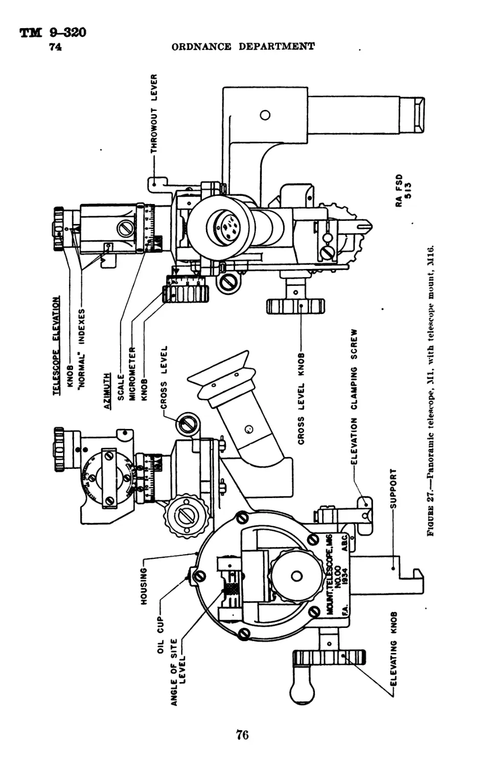
Parts to be inspected
k. Trails (М3Al, М3,
and M2A1).
Z. Trails, front, rear
(Ml).
m. Wheels (M3A1, М3,
and M2A1).
n. Tra veli ng lock
(M3A1, М3, and M2A1).
o. Traversing rack
(M3A1, М3, and M2A1).
p. Firing base (M3A1,
М3, and M2A1).
Sighting system.
Points to observe
k. Note that the trails swing freely
and that the trail hinge pins are properly
lubricated. Examine the trail connect-
ing lock. Note that it performs its func-
tion without undue force. Note that the
lunette turns freely. Examine all sup-
ports and fastenings welded to the trail
. for defects.
Z. Condition of axle bearings. Smooth-
ness of operation and lubrication of trail
connecting mechanism. Condition of
hinges, spades and spade points, and
straps and fastenings.
m. Examine the disk and rim wheel
nuts. Note condition and that they are
set up tight. Note whether the rim of
the disk is deformed. Examine the tires.
Note whether the crown of the tire is
taking the wear. If worn to the left or
the right test alinement of wheels with a
string or tape, measuring the horizontal
distance between the centers of the tin's
on a wheel diameter. The maximum al-
lowable variation is % inch.
n. Examine the traveling lock. Note
that it swings into position without force.
o. Examine the traversing rack for
broken or deformed teeth. Note that
the traversing stops are in place and in
good condition.
p. Examine the firing base for defects.
Swing it to and fro and note action of
latches.
q. Inspect for general appearance and
lubrication. Note undue lost motion in
the operation of the various gears.
Check the level vials to insure that they
are tightly secured in their holders.
Inspect the alinement and, if necessary,
adjust.
30
TM 9-320
57—58
75-MM HOWITZER MATERIEL
Section IX
MALFUNCTION AND CORRECTION Рям .
rarajrrapn
General_______________________________________________________ 57
Malfunction of howitzer-------------------------------------- 58
Malfunction of carriage--------------------------------------- 59
57. General.—The functioning of the materiel as a whole is so
closely allied with description and operation that it has been included
in sections II, III, IV, V, and VII, and is not repeated hereunder.
58. Malfunction of howitzer.
Malfunction
a. Fails to fire;
no percussion on
primer.
b. Fails to fire
until after several
percussions on
primt'r.
Cause
a. Broken firing
spring. Broken or
deformed firing pin.
b. (1) Firing mech-
anism parts not
working freely.
c. Fails to fire
when proper per-
cussion on primer
is obtained.
d. Fails to ex-
tract empty case'.
(2) Weak firing
spring.
с. I) e f e c t i v e'
primer.
Correction
a. Disassemble' firing
lock and replace broken
or deformed part.
b. (1) Disassemble fir- •
ing lock and examine'
carefully for burs anel
roughened surfaces. Re-
move burs and smooth
roughene'd surfaces with
crocus cloth or an oil-
stone. Wash parts with
dry cleaning solvent to
remove gummy oil; dry
thoroughly and lubricate'
with oil SAE 10W or SAE
20, depending on temper-
ature', before reassembly.
(2) Replace.
c. Replace.
d. В г о к e' n e x -
t ractor.
</. Carefully remove
the case by operating
from the muzzle end.
Examine the edge of the
chamber for deformation
or burs which might
cause difficult extraction.
Disassemble mechanism.
Replace extractor if
necessary.
31
ТМ 9-320
59
ORDNANCE DEPARTMENT
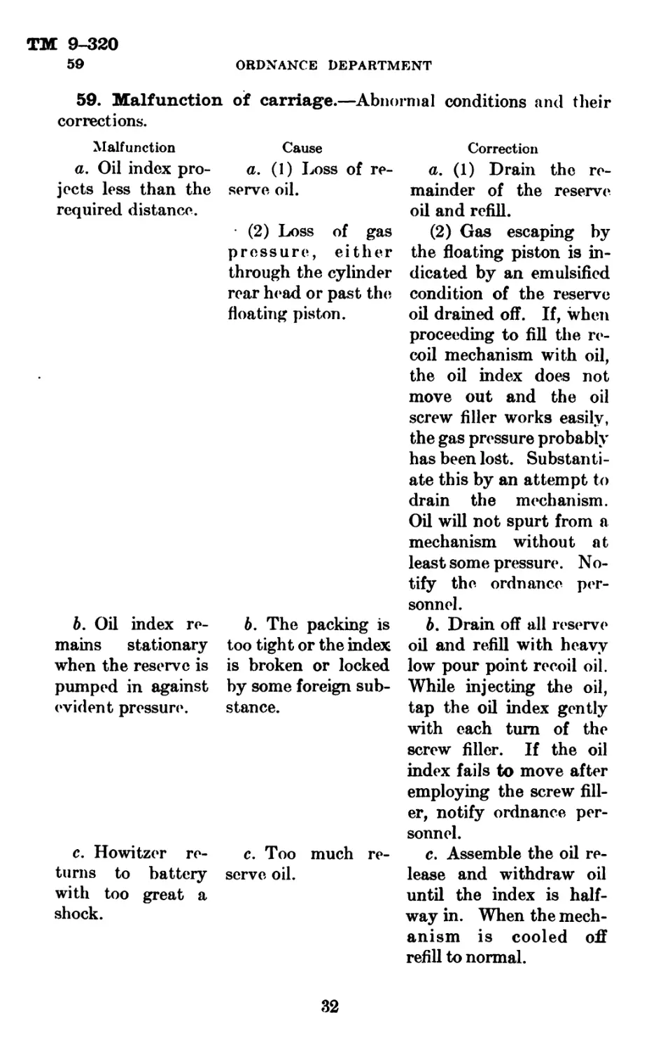
59. Malfunction
corrections.
of carriage.—Abnormal conditions and their
Malfunction Cause
a. Oil index pro- a. (1) Loss of re-
jects less than the serve oil.
required distance.
(2) Loss of gas
pressure, either
through the cylinder
rear head or past the
floating piston.
b. Oil index re-
mains stationary
when the reserve is
pumped in against
evident pressure'.
6. The packing is
too tight or the index
is broken or locked
by some foreign sub-
stance.
c. Howitzer re-
turns to battery
with too great a
shock.
c. Too much re-
serve oil.
Correction
a. (1) Drain the re-
mainder of the reserve
oil and refill.
(2) Gas escaping by
the floating piston is in-
dicated by an emulsified
condition of the reserve
oil drained off. If, when
proceeding to fill the re-
coil mechanism with oil,
the oil index does not
move out and the oil
screw filler works easily,
the gas pressure probably
has been lost. Substanti-
ate this by an attempt to
drain the mechanism.
Oil will not spurt from a
mechanism without at
least some pressure. No-
tify the ordnance per-
sonnel.
b. Drain off all reserve
oil and refill with heavy
low pour point recoil oil.
While injecting the oil,
tap the oil index gently
with each turn of the
screw filler. If the oil
index fails to move after
employing the screw fill-
er, notify ordnance per-
sonnel.
c. Assemble the oil re-
lease and withdraw oil
until the index is half-
way in. When the mech-
anism is cooled off
refill to normal.
32
TM 9-320
59-60
75-MM HOWITZER MATERIEL
Malfunction Cause
d. Howitzer fails d. (1) Insufficient
to return to battery, oil reserve.
(2) Low nitrogen
gas pressure.
(3) Excessive fric-
tion.
(4) Damaged slides,
piston rod, or piston.
(5) Leakage of oil
past recoil piston.
Correction
d. (1) Withdraw the
reserve oil. Establish a
new full reserve.
(2) Notify ordnance
personnel.
(3) Notify ordnance
personnel.
(4) Notify ordnance
personnel.
(5) Remove cap screw
in rear head of recoil
cylinder, elevate piece,
and allow oil to escape
through screw opening.
Section X
CARE AND PRESERVATION
Paragraph
Howitzer_________________________________________________________ 60
Carriage___________________________________________________________ 61
Recoil mechanism_______________________________________________ 62
Recoil oil_______________________________________________________ 63
Brake mechanism and wheel hearings______________________________ 64
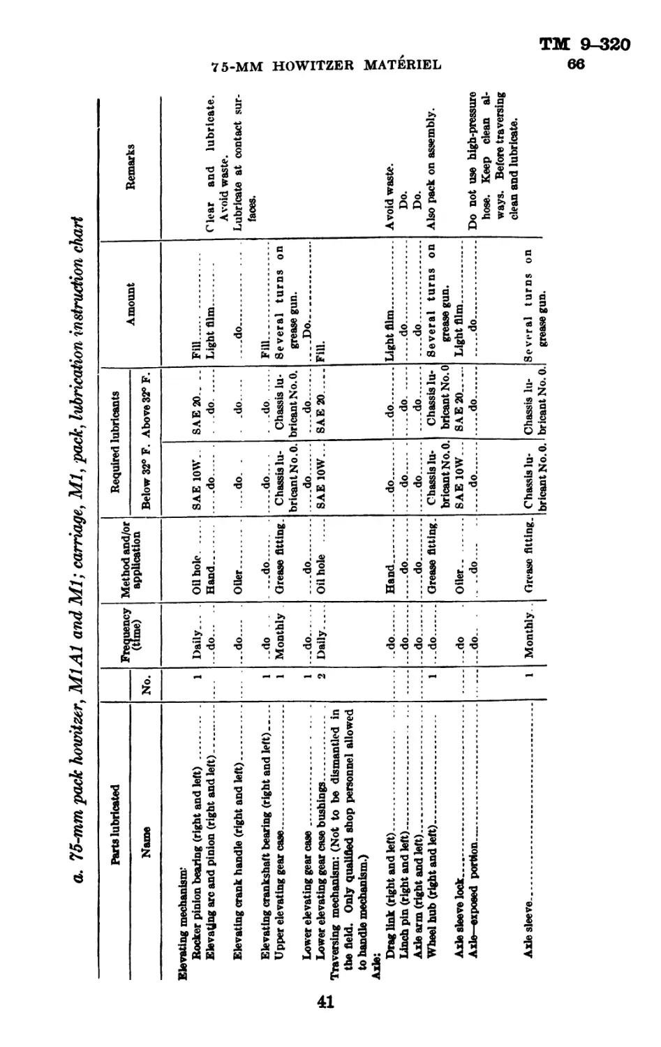
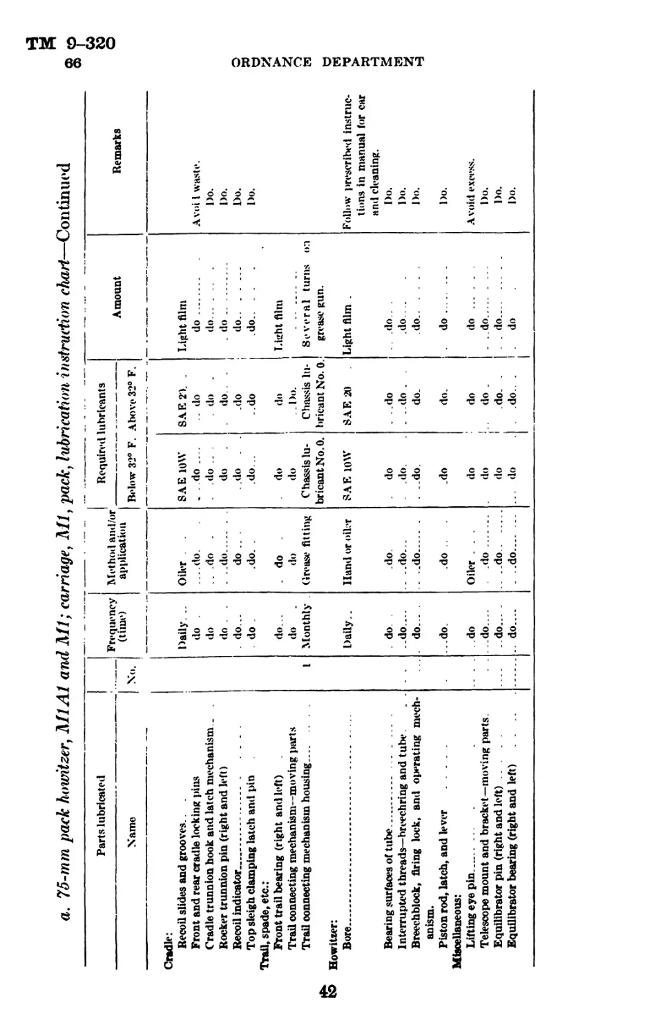
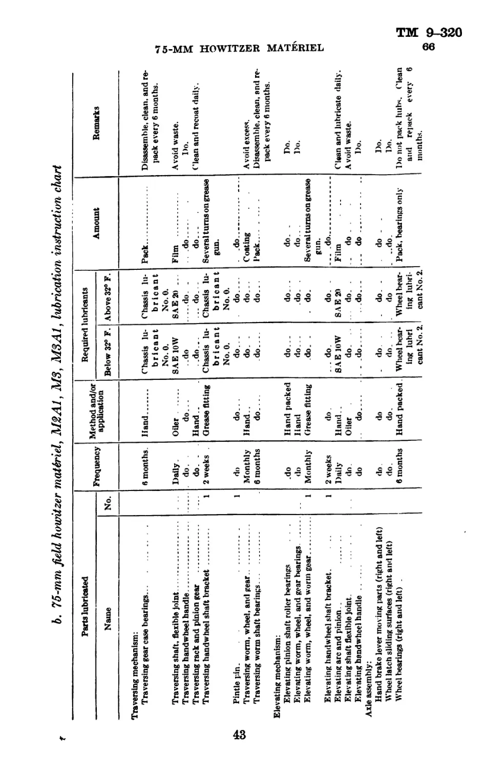
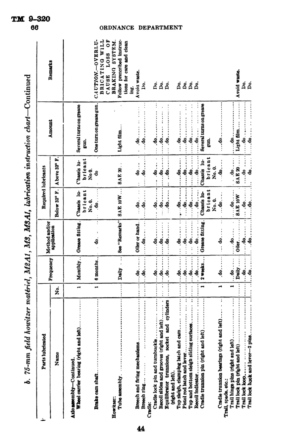
Lubrication instructions_____________________________________ 65
Lubrication charts____________________________________________ 66
Cleaners and abrasives_________________ _ _________ _________ ______ 67
Preservatives_________________________________________________ 68
Paint and related materials__________ _ ... ----------- --------- 69
Lubricants___________________________ _____ _______ . __ 70
Miscellaneous materials and tools______________ ____________________ 71
60. Howitzer.—a. (1) It is important that whenever the rate of
fire permits, the cannoneer examine the bore before each loading to
ascertain whether or not particles of cartridge case, wadding, or
unburned powder remain in the bore. The presence of such particles
may cause damage to the piece. During night firing the sponge
should be used between rounds.
(2) Should enemy shell burst near the weapon, be sure before
firing that the weapon has not been damaged to a dangerous degree.
Damage of a serious nature should be reported to the ordnance
officer.
(3) In cleaning after firing, wash the bore with a solution of
half a pound of soda ash or a pound of sal soda in a gallon of water.
Use the bore brush or a piece of burlap or cleaning cloth around the
319275°—41---3
33
ТМ 9-320
60 ORDNANCE DEPARTMENT
metal end of the rammer staff for swabbing. When all powder foul-
ing has been removed, swab the bore with clear water and dry with
a piece of clean burlap or cleaning cloth. Finally coat the bore with
lubricating oil, SAE 10W for temperatures less than 32° F., and
SAE 20 for temperatures greater than 32° F.
(4) The leveling plates should be protected. Tools or other articles
will not be placed upon them. In case of injury repair must be
made by ordnance personnel.
(5) Lubricating instructions are given in paragraph 65.
(6) When the materiel is not in use covers must be used.
(7) When the weapon is to be unused for a considerable time the
bore, breech mechanism, and bright and unpainted surfaces should
be cleaned with dry cleaning solvent and the surfaces coated with
medium rust preventive compound.
b. Breech mechanism.—(1) Should be kept clean and the parts
well lubricated. When not in use disassemble periodically, especially
for detection of rust. When in use disassemble frequently and clean
and oil. It should be so cared for immediately after firing.
(2) In removing rust preventive compound the greater part should
be scraped off. That remaining should be removed with dry cleaning
solvent used on a rag or waste.
(3) A steel hammer must not be used directly on any part of
the mechanism. A buffer such as a hardwood block should be inter-
posed, or a copper hammer used.
(4) If the breechblock does not slide smoothly it should be examined
for burs or scoring. Burs should be removed and the breechblock
should be coated with Engine Oil SAE 10W for temperatures below
32° F. and Engine Oil SAE 20 for temperatures above 32° F. If
the breechblock is scored, the condition should be reported to the
ordnance maintenance company.
c. Firing mechanism.—(1) The parts require the same attention
as the breech mechanism. Therefore, frequent disassembly for the
purpose of cleaning and oiling is required.
(2) Fouling of the firing pin, or the use of a thicker oil than
authorized will cause absorption of the energy of the spring and
firing pin holder and may result in misfire. This is especially true
in cold weather.
(3) Wear in this mechanism is negligible. Deformation of the
front end of the firing pin may cause sticking in the breechblock
bushing. If the firing pin is examined after each firing, replacement
can be anticipated.
34
ТМ 9-320
75-MM HOWITZER MATERIEL 61-62
61. Carriage.—o. Attention should be given to cleaning, lubrica-
tion and loose or broken parts. Lubrication, with the method and fre-
quency of application, is covered in detail in paragraphs 65 and 66.
b. Bearing surfaces, revolving parts, springs, gear teeth, breech
mechanisms, screw threads, and exterior parts must be clean and
free from dirt. Special attention should be given to exposed gear
teeth and bearing surfaces. In disassembling and assembling op-
erations, precautions must be taken to prevent the entrance of foreign
matter.
c. The carriage should be given a general inspection periodically.
d. The care and maintenance of the carriage require the use of
the cleaning and preserving materials issued by the Ordnance
Department.
e. When the carriage is stored, or is to remain unused for a con-
siderable length of time, all bright and unpainted surfaces should
be protected with a coat of medium rust preventive compound.
Before applying the compound the surfaces should be cleaned with
dry cleaning solvent.
62. Recoil mechanism.—a. Before firing, the recoil mechanism
should be examined for leakage of oil and to assure that the proper
amount of reserve oil is in the system, and that the howitzer sleigh
slides are well lubricated.
&. During firing, the action of the mechanism should be noted, and
the following operations checked:
(1) Howitzer recoils its prescribed distance.
(2) Howitzer returns into battery without shock.
(3) Leakage of oil from the filling and drain hole, oil index recess,
and the front of the recoil cylinder is not excessive.
c. Oil reserve.—Firing should not be undertaken with an excess
or lack of reserve oil. The amount of oil reserve in the system is
shown by the position of the oil index with reference to the extension
on the oil index follower assembled in the recuperator cylinder front
head, as follows:
(1) No reserve.—The indicator is well into the recess.
(2) Full reserve.—The end of the indicator is flush with the ex-
tension on the oil index follower.
(3) Excess reserve.—The oil index does not of itself show when
there is an excess of oil reserve, as the addition of excess oil does
not move the index out beyond the follower.
d. To reduce or exhaust oil reserve.—In draining the reserve oil
from the recoil mechanism, provide a clean receptacle of at least
35
TM 9-320
62 ORDNANCE DEPARTMENT
1-pint capacity. Unscrew the filling plug, using the ratchet wrench
and the ^-inch socket. Assemble the oil release into the filling hole.
The reserve oil will spurt out in a stream and suddenly drop at right
angle to the flow. At this point the flow of oil should be stopped by
unscrewing the filling and drain valve release. It will be noted that
the oil index has moved out of sight. If the oil index has not moved
tap it gently with a small piece of wood, as it may be bound by
the index packing.
e. To establish a new oil reserve.—(1) Fill the body of the oil screw
filler with low pour point heavy recoil oil. Hold the filler nozzle up
and give the screw a turn or two until a small amount of oil . runs
out, in order to expel all air from the filler. Screw the nozzle of
the oil screw filler into the filling hole; give the handle of the filler
another turn to force out any air in the filling hole; then tighten
the oil screw filler. Operate the oil screw filler, using both hands
to avoid forcing it to one side and breaking off the threaded nozzle.
(2) When the oil index has reached its extreme outward position,
that is, flush with the extension on the oil index follower, a full oil
reserve is present in the mechanism.
(3) In the event of the oil index’s not moving into position after
filling the system with reserve oil the ordnance maintenance company
should be notified.
(4) In emergency if the oil index fails to register, the reserve oil
in the system should be drained. The flow and sudden stoppage of
the oil will prove that the mechanism is serviceable. Refill the
mechanism with one-half screw filler of oil and proceed to fire the
piece.
(5) Remove the oil screw filler and replace the filling plug.
/. Nonfunctioning of oil index.—(1) Sometimes the oil index does
not register when oil is being injected. On this account, an excessive
amount of oil may be injected.
(2) An excessive amount of oil is dangerous as during recoil the
control rod will jam. This will damage or may cause destruction of
the recoil mechanism.
(3) If the oil index does not move in when the oil is being ex-
tracted, or if it does not move out when oil is being injected, it is
probable that the packing around the oil index is too tight. On the
other hand the index may be broken or frozen.
(4) In order to test the oil index, drain, by means of the filling and
drain valve release, all the oil that will run out. After removing the
filling and drain valve release, inject the oil by means of the oil screw
filler. While injecting the oil tap the index lightly on each turn of
36
ТМ 9-320
75-MM HOWITZER MATERIEL 62-63
the oil screw filler. If the index does not move out after about half
the capacity of the oil screw filler has been injected, it is an indication
that there is something wrong with the mechanism and the ordnance
officer should be notified. Should the index work properly after the
operation described the reserve oil supply should be injected and
drained off about three times to insure that the index is in working
condition.
g. Use of recoil mechanism in emergency.—In an emergency it may
become necessary or desirable to fire the howitzer without reference
to the action of the oil index. The procedure is to assemble the filling
and drain valve release and extract all the reserve oil. Refill the
mechanism with one-half fill of the oil screw filler. Remove the oil
screw filler and assemble filling and drain plug. Firing may then
proceed until the howitzer returns into battery with shock. Shock
indicates that heat has expanded the reserve oil and that some of it
should be released. If the mechanism is losing oil through leakage
around packing, firing may continue until the howitzer does not return
into battery position.
A. General care.—All nonbearing surfaces should be kept painted.
Bearing surfaces must be clean and lubricated.
63. Recoil oil.—a. General.—(1) The recoil mechanisms use
heavy recoil oil with low pour point. Care must be taken not to use
other than that prescribed.
(2) Water must not be introduced into recoil mechanisms that use
oil.
(3) Exposure of recoil oil in an open can may result in accumula-
tion of moisture. Condensation in a container partly filled with oil,
or pouring from one container to another which has moisture on its
inner walls, results in moisture being carried along with the oil into
recoil mechanisms.
(4) It is advisable that recoil oil be tested for water. Use a clean
glass bottle of 1-pint capacity filled with recoil oil. The oil should
be allowed to settle. If water is present, the water being heavier
than the oil, will sink to the bottom. With the bottle slightly tilted,
drops or bubbles will form in the lower portion. Invert the bottle
and hold to the light. Drops or bubbles of water, if present, may be
seen slowly sinking in the oil. If the oil has a cloudy appearance
the cloudiness may be ascribed to particles of water. Another test
is to heat a shallow pan of oil to boiling. Water in the oil will
appear on the surface as minute bubbles. This test will disclose
water not determinable by the settling test.
(5) Should either of these tests show water, the oil on hand should
be turned in.
37
ТМ 9-320
63—64 ORDNANCE DEPARTMENT
6. Care of recoil oik—The transfer of recoil oil to a container
not marked with the name of the oil may result in the wrong oils
getting into recoil mechanisms, or in the use of recoil oil for lubri-
cating purposes. Recoil oil must not be put into any container not
marked with the name of the oil. The following should also be ob-
served. Recoil oils should not be left in open containers or subjected
to excessive heat. The greatest care must be taken with recoil oils
to exclude moisture and dirt. Strain through clean cloth before
inserting in recoil mechanism. Do not mix recoil oils with any
other type of oil.
64. Brake mechanism and wheel bearings.—a. Brake ad-
justment of the 75-mm howitzer carriage, M3A1, is accomplished by
rotating the brake shoe adjusting wedge, B144959, which extends to
the outside of the brake housing plate, C62668, in the desired direc-
tion. The outside end of the adjusting wedge is machined with a
square for turning with a wrench. The correct procedure for ad-
justing the brakes is as follows: (See figs. 21 and 22.)
(1) Set brake lever at full released position.
(2) Jack up the wheel.
(3) Adjust the brake adjusting wedge until a drag is felt on
the wheel. Then back off just enough so that the brake does not
drag. Brake must be cold when making adjustment.
Ъ. (1) To adjust the external brake of the 75-mm howitzer car-
riages, М2 Al and М3, clean and lubricate the exposed parts of the
brake mechanism.
(2) Set the brake lever to full released position.
(3) Jack up the wheel.
(4) Advance the brake band adjusting nut, A137462, on the brake
band adjusting screw, A137994, until the brake lining just touches
the brake drum. Equalize the brake band about the brake drum by
means of screw, A137598. (See fig. 20.)
(5) Revolve the wheel and see that it turns freely and without,
drag.
(6) Set up on the brake lever and note position of the brake ratchet
pawl on the ratchet rack. If the pawl is beyond the center of the
rack release the brake lever and advance the adjusting nut, A137462,
one or two turns. Continue these operations until the pawl is in
about the center of the rack. Then release the brake lever to its full
“off” position and revolve the wheel to see that it turns freely and
without drag.
c. Wheel bearings should be adjusted to prevent brake drag due to
loose bearings.
38
TM 9-320
64-65
75-MM HOWITZER MATERIEL
d. The brake cam, B144968, and rollers, B144955, are lubricated
through a button head fitting. Lubrication must be held to the cor-
rect amount to keep the brake lining from becoming saturated with
oil or grease. This condition will demand heavy brake lever pres-
sure and the replacement of brake linings prematurely. Molded
lining may be cleaned with dry cleaning solvent to remove oil or
grease. (See fig. 21.)
e. Roller bearings in the wheel hubs should be examined every 6
months when in service, washed in dry cleaning solvent, and hand
packed with wheel bearing grease. The hub should also be cleaned
but not packed. All lost motion should be eliminated (without bind-
ing the bearings) by means of the slotted nuts, BBHX2A, on the
wheel carrier (fig. 21) and on the spindle (fig. 19). After the spindle
bearings are adjusted, the adjustment should be checked by placing
a bar between the raised tire and the ground, at the same time holding
one finger on the cage of the outer bearing. When, in working the
bar up and down, a barely perceptible shake is felt, and the wheel
will rotate when given a slight spin, the adjustment is correct. This
adjustment is obtained normally by tightening the wheel spindle nut
with a wrench having an 8-inch handle and then backing off the nut to
the nearest castellation.
/. Tires should be kept inflated at a pressure of 30 pounds per
square inch.
Note.—The pressure stamped on the tires should be disregarded.
65- Lubrication instructions.—a. Excessive wear can be pre-
vented by keeping the materiel clean and well lubricated. The life of
the materiel depends on proper lubrication. Particular attention
should be given to sliding and bearing surfaces of the cradle and
breech mechanism.
Ъ. Lubricating oils and greases as shown in the lubrication chart
must be used as prescribed.
d. Gear cases and other parts packed with grease should be cleaned
and repaced every 6 months. Other moving parts, not specifically
mentioned, should be cleaned and a film of oil, SAE 10W below 32°
F. and SAE 20 above 32° F., applied.
d. Lubricating fittings will be painted red for ease in locating. Oil
holes are encircled by a red ring.
e. The oil gun should be worked slowly and the parts oiled should
be maneuvered to insure proper distribution of the lubricant.
/. Should an oiler valve stick and prevent the passage of the oil. it
may be loosened with a piece of wire pushed through the hole.
Care should be taken not to damage the valve.
39
ТМ 9-320
65—66
ORDNANCE DEPARTMENT
g. Care must be taken when cleaning oil and grease compartments
to insure the complete removal of all residue or sediment. Dirt or
other foreign matter should not be allowed to drop into any of the
lubricating compartments.
Л. When cleaning the gun, operating personnel are cautioned to
refrain from playing water from the high-pressure hose directly
against the trunnion bearings or trail pin housings, since this will
result in water entering into the bearings and cause nonfunctioning
of the operating parts.
i. Lubrication frequencies are based on continuous use of the mate-
riel with frequent firing.
j. No lubricants will be used other than those prescribed, without
the authority of the Ordnance Department.
66. Lubrication charts.—The following lubrication charts are
provided:
40
a. 75-mm pack howitzer, Ml Al and Ml; carriage, Ml, pack, lubrication instruction chart
Parts lubricated Frequency (time) Method and/or Required lubricants Amount Remarks
Name No. application Below 32° F. Above 32° F.
Elevating mechanism: Rocker pinion bearing (right and left) . Elevating arc and pinion (right and left) _ Elevating crank handle (right and left) Elevating crankshaft bearing (right and left) Upper elevating gear case 1 1 Daily... . ...do ...do do Oil hole Hand Oiler . ...do SAE 10W. do . ...do. . do... . SAE 20. . ..do . .do . ..do Fill Light film do Fill Clear and lubricate. Avoid waste. Lubricate at contact sur- faces.
1 Monthly . do. Orease fitting. do.... Chassis lu- Chassis lu- Several turns on
Lower elevating gear case Lower elevating gear case bushings. . Traversing mechanism: (Not to be dismantled in the field. Only qualified shop personnel allowed to handle mechanism.) Axle: Drag link (right and left).... ... Linch pin (right and left). .. ... Axle arm (right and left) Wheel hub (right and left) Axle sleeve lock.... 1 bricant No.0. do bricant No. 0. ....do.. grease gun. Do
2 Daily ..do Oil hole Hand do do Orease fitting. Oiler.. SAE 10W... . do SAE 20 do Fill. Liffht film Avoid waste.
1 ...do ...do ...do do . do.. Chassis lu- do ....do Chassis lu- do ....do Several turns on Do. Do. Also pack on assembly.
...do bricant No. 0. SAE 10W... bricant No.0 SAE 20 grease gun. Light film
Axle—exposed portion ...do.. . .. ..do.... do do do Do not use high-pressure
Axle sleeve. 1 Monthly.. Grease fitting. Chassis lu- Chassis lu- Several turns on hose. Keep clean al- ways. Before traversing clean and lubricate.
bricant No.0. bricant No. 0. grease gun.
75-MM HOWITZER MATERIEL
a. 75-mm pack howitzer, Ml Al and Ml; ca rriagc, Ml, pack, lubrication instruction chart—Continued s p GO to О
Parts lubricated Frequency (time) Method and/or application | Required lubricants Amount Remarks
Name
Below 32° F. Above 32° F.
Cradle:
Recoil slides and grooves.. . Daily. .. Oiler SAE 10W SAE 2). . Light film
Front and rear cradle locking pins do . ....do. . . do .... .. do do Avoi I waste.
Cradle trunnion hook and latch mechanism . . do .. do . do .. . . do . do Do.
Rocker trunnion pin (right and left) do . . . ..do do do . do .. Do.
Recoil indicator . .... . do... do .. . . do . . .do । do Do. о
Top sleigh clamping latch and pin . do . .do. . .do... ..do do Do. о
Trail, spade, etc.:
Front trail bearing (right and left) do... do do do 1 Light film >
Trail connecting mechanism—moving parts Trail connecting mechanism housing.. do do do .Do.
I Monthly . Urease fitting Chassis lu- Chassis lu- Several turns on и
fe Howitzer: bricant No. 0. bricant No. 0. grease gun.
Bore... Daily.. Hand or oiler SAE 10W SAE 20 Light film . Follow prescribed instruc-
tions in manual for car > я
and cleaning. ч
Bearing surfaces of tube . do. . .do. do . . .do .. .do.. . Do. £
Interrupted threads—breechring and tube». . . ..do... .. ..do... .do. . ..do . . .do Do. и
Breechblock, firing lock, and operating mech- do... . .. ..do . . ..do. do- do Do. ч
anism. Piston rod, latch, and lever ... do. .do .. .do do. do Do.
Miscellaneous:
Lifting eye pin . do Oiler . . . do do do Avoid excess.
Telescope mount and bracket—moving parts. . ..do.... . .do do ; .. do . . ..do .... Do.
Equilibrator pin (right and left) ..do... . .. ..do do ' do. . . . do Do.
Equilibrator bearing (right and left) .. do.... . ..do ... do | . .do.. . do 1 Do.
b, 75-mm field howitzer materiel, М2 Al, MS, MS Al, lubrication instruction chart
Parts lubricated Frequency Method and/or application Required lubricants Amount Remarks
Name No. Below 32° F. Above 32° F.
Traversing mechanism: Traversing gear case bearings . . 6 months. Hand Chassis lu- bricant No. 0. Chassis lu- bricant No. 0. Pack Disassemble, clean, and re- pack every 6 months.
Traversing shaft, flexible joint Traversing handwheel handle Traversing rack and pinion gear Traversing handwheel shaft bracket Pintle pin. . Traversing worm, wheel, and gear 1 1 Daily. . do. do. . . 2 weeks . do Monthly Oiler do... Hand.. Grease fitting do.. . Hand.. SAE 10W . .do ..do... Chassis lu- bricant No. 0. do.. . do. SAE 20 ... do. _ ... do.. . Chassis lu- brlean t No. 0. do do... Film .. .do do... Several turns on grease gun. . .do.... Coating Avoid waste. g Do. g ('lean and recoat daily. § H . .. N Avoid excess. д
Traversing worm shaft bearings Elevating mechanism: Elevating pinion shaft roller bearings . . . 6 months .do do.... Hand packed do.... do.. _ do... do... Pack. do. . Disassemble, clean, end re- $6 pack every 6 months. g > Do. 4
Elevating worm, wheel, and gear bearings Elevating worm, wheel, and worm gear Elevating hand wheel shaft bracket. .. Elevating arc and pinion.. Elevating shaft flexible joint. Elevating handwheel handle Axle assembly: Hand brake lever moving parts (right and left) Wheel latch sliding surfaces (right and left) Wheel bearings (right and left) . 1 1 do Monthly 2 weeks Daily do. do do. do. 6 months Hand Grease fitting do. Hand.. Oiler do do do. Hand packed. do.. . do. . ... do. SAE 10W do. . . .do do. . do. .. Wheel bear- ing lubri 1 cant No. 2. .do. . . do. do. . SAE 20 ... do. . .. .do do. . do Wheel bear- ing lubri- cant No. 2. do . . Several turns on grease gun. ... .do Film do . . ... do do . . . ..do. Pack, bearings only Do. S' h-( M Clean and lubricate daily. Avoid waste. Do. Do. Do. Do not pack huhK. Clean and repack every 6 Ы months. M 4 g
b. 75-mm field howitzer materiel, М2 Al, M3f MS Al, lubrication instruction chart—Continued a a в p GO §
I' Parts lubricated Frequency Method and/or application Required lubricants Amount Remarks
Name No. Below 32° F. Above 32° F.
Axle assembly—Continued.
Wheel carrier bearing (right and left) 1 Monthly.. Grease fitting. Chassis lu- Chassis lu- Several turns on grease
bricant bricant gun.
No. 0. No 0.
Brake cam shaft 1 6 months.. . do. . . .do. .... do One turn on grease gun. C.l UTZCW.—OVERT,U- BR1CAT1NG WILL o
CAUSE LOSS OF 56 ©
Howitzer: BRAKING SYSTEM. *
Tube assembly Daily . .. See “Remarks” SAE 10W... SAE 20. . Light film... Follow prescribed instruc- tions for care and clean £ Q
ing. W
£ Breech and flring mechanisms Breech ring Cradle: ...do . .do Oiler or hand.. do ... ...do.. .. do do... . do. .do... ...do Avoiu waste. Do. О M и
Cradle lock pin and turnbuckle ...do do .—do ... .do... . ... .do Do. > 56
Recoil slides and grooves (right and left) ...do do ... do do do Do.
Equilibrator trunnions, socket and cylinders . .do do .do .. ..do do Do. £
(right and left). M
Top sleigh, clamping latch and cam ...do ... .do .do do ...do . Do.
Pistol rod latch and lever Top and bottom sleigh sliding surfaces — ...do ...do do do. . ...do do do do do do.._ Do. Do.
Recoil indicator Cradle trunnion pin (right and left).. 1 . .do 2 weeks... .... do Grease fitting. .—do Chassis lu- do Chassis lu- do.._. ... Several turns on grease Do.
brleant bricant gun.
No. 0. No. 0.
Cradle trunnion bearings (right and left).... Trail, spade, etc.: 1 .do ... do . ...do.... do ....do
Trail hinge pins (right and left) .... Trail lock pin (right and left) Trail lock loop - 1 ...do Daily ...do do . Oiler do do SAE 10W . ... .do . . .do SAE 20 ....do __... do. Light film do. Avoid waste. Do.
Trail lock hook and lever—2 pins ... .. L.-do .. -do 1 do do do Do.
Miscellaneous:
Firing base lock plunger and pedal pin . .do do._
Firing base (traveling lock) hinge pin (right and ...do do..
left).
Liftingeye pin . . .. .do do..
Telescope mount and bracket moving parts . . do . ...do..
Sighting chest hinge strap .. do . do _
Staff support—2 pins . ..do. . ..do..
Bange quadrant and bracket—moving parts do .. .do..
..do ..do do do ... .do ... .do Do. Do.
..do.... . .do.... . .. ..do Do.
. .do .. .do .do . Do.
. .do... . do. . . .do Do.
..do.. . . do .do Do.
do. . . do.... 1 .. .do Do.
z
g
ТМ 9-320
67
ORDNANCE DEPARTMENT
67. Cleaners and abrasives.—See TM 9-850 (now published as
TR 1395-A) for those prescribed and their application and use.
The following are prescribed:
Burlap, jute, 8-ounce (40 inches wide).
Cloth, crocus.
Cloth, emery.
Compound, cleaning.
Compound, rust preventive, medium.
Lime, hydrated.
Paper, for cleaning optical glass.
Paper, flint (sandpaper).
Polish, metal, paste.
Remover, paint and varnish.
Soap, castile.
Soda ash.
Soda, caustic (lye). for cleaning purposes.
Solvent, dry cleaning.
Sponge.
Waste, cotton, white.
a. Soap, castile.—(1) Used for cleaning leather equipment and as
a component of saddle soap.
(2) The action of soap depends upon a chemical combination of
alkalies in the soap and the grease which is to be softened and re-
moved. The resulting soapy compound is readily washed off, leaving
nothing to hold the dirt. The soap will thus remove some of the
oil in the leather and repeated washings will probably require re-
placement of oil to prevent the leather from becoming harsh and
brittle.
(3) Nearly all ordnance leather equipment is russet leather. When
it becomes soiled it should be cleaned by carefully removing all
hardened grease with a sliver of wood (not glass or knife) and wash-
ing with a sponge saturated with a heavy lather of castile soap and
clean tepid water. Rinse thoroughly and rub vigorously with a dry
cloth until the leather is dry. Straps and other articles of unvar-
nished harness leather which become dry and brittle should be cleaned
as described and while the leather is still slightly moist, be given
an exceedingly light coat of neat’s-foot oil by rubbing with a
soft cloth moistened (not saturated) with the oil. Wipe off any oil
that the leather does not absorb. In cold weather the oil may be
heated luke warm (never hot) and the article, after being oiled,
hung in a warm place. Shellacked sole leather cases do not require
oiling.
46
TM 9-320
67-68
75-MM HOWITZER MATERIEL
(4) Russet leather, as manufactured, is stuffed with a dubbing of
cod liver oil and tallow, which is absorbed to the extent that the
quality of the leather is improved and its life prolonged, but not
enough oil remains on the surface to soil the clothing if the equip-
ment is properly cared for. It should be noted that in the washing
and oiling described above, if more than a light coat of oil be given,
the leather will be greatly darkened and will quickly soil the clothing.
No method of cleaning will then restore the original light color of the
leather or remove stains from it.
(5) Articles of black leather may be cleaned with castile soap,
rinsed, and, when nearly dry, lightly sponged with a mixture of 1
teaspoonful of lampblack in 1 pint of neat’s-foot oil, the mixture
having been first stirred until it has a glossy black appearance. The
mixture should then be well rubbed into the leather. Leather equip-
ment which has become wet should be dried in the shade. Wet
leather exposed to the sun or to too high a heat from a stove or
radiator becomes hard and brittle.
b. Sponges,—Used for washing and cleaning material. Natural
sponges may be substituted by cellulose sponges in sizes Nos. 4. 6. 8,
and 10 (approximate dimensions I1/! by 3% by 4%; 1% by 3y2 by
5*4; 2 by 3% by 6%; 2^ by 4% by 6y2). These latter sponges must
not be wrung. Squeezing only is the proper method.
c. 'Waste, cotton.—There are two grades, colored and white.
(1) The colored cotton waste is used for general cleaning purposes
on the exteriors of ordnance materiel such as gun carriages and auto-
motive vehicles. It is also used as calking for cracks from which
it is desired to exclude dust and dirt.
(2) White waste is used for general cleaning purposes on finished
surfaces of ordnance materiel. In lieu of white cotton waste an
equivalent amount of clean wiping cloths may be used.
68. Preservatives.—See TM 9-850 (now published as TR
1395-A) for information on rust, corrosion, inspection for corrosion,
rust preventives, preparation of metal surfaces for slushing, method
of slushing, inspection of grease films, and storage conditions.
a. Naphthalene, -flake,—(1) A flaked form of moth ball.
(2) Used as a moth repellant to preserve the linings of helmets,
felt wads, felt packings of instrument chests, carpet, gun sponges,
and paint and varnish brushes. It is sprinkled thickly on the arti-
cles, which should, if possible, be then wrapped in paper covers and
tightly boxed. The materiel should be thoroughly brushed and aired
before packing and should be periodically inspected. If there are
any signs of devastation by the moth larvae the articles must be
unpacked, cleaned, and recharged with naphthalene.
47
ТМ 9-320
68-69
ORDNANCE DEPARTMENT
&. Naphthalene should be used in airtight receptacles in order to
obtain a concentrated naphthalene vapor.
69. Paint and related materials.
Enamel, red, water-resisting.
Enamel, synthetic, olive drab, lusterless (QM specification ES
No. 474b).
Enamel, white.
Lacquer.
Lead.
Mixture, liquid, for red lead paint.
Oil, linseed, raw.
Paint, ready mixed, red, commercial.
Paint, stencil, black.
Paint, stencil, white.
Thinner (for enamel, synthetic, olive drab, lusterless) (QM
specification ES No. 370a).
Turpentine.
Varnish, shellac, orange.
a. Oil paints and their application.—(1) Paint is used for preser-
vation against rust, deterioration, and decay of metals and woods.
Some paints adhere to metal surfaces better than others, the liquids
of the first or base coat seeming to penetrate very minute depressions
or pits in the metal or to etch themselves into the surface and thus
form a good bond for following coats. The paints are issued mixed
and ready to apply, except in a few instances. Paint stored in large
containers should be well stirred before transfer to smaller containers.
Ordnance materiel is well painted before issue and one maintenance
coat per year should be ample for protection. The final coat must in
all events be olive drab lusterless enamel ES No. 474b.
(2) Red lead paint is a good base coat on iron or steel. Red lead
possesses no particular advantages as a base coat on nonferrous
metals. Red lead paint does not keep well and must be mixed as
needed. The formula for 1 gallon of it is 20 pounds of dry red lead
with 3 quarts of liquid mixture. The usual process of mixture is
to place a small amount of dry red lead in a suitable container, work
a little of the mixture into it to form a paste, and then stir the rest
of the liquid mixture into it.
(3) All ordnance material shall be painted with lusterless flat
enamel.
(4) Olive drab flat lusterless enamel may be applied over the pres-
ent long oil enamel and oil paint issued by the Ordnance Department.
Method of application may be by brush or spray. It may be brushed
on satisfactorily when used unthinned in the original package con-
48
ТМ 9-320
75-MM HOWITZER MATERIEL 69
sistency; or when thinned no more than 5 percent of volume with
thinner, QM specification ES No. 370a. The enamel will spray
satisfactorily when thinned with 15 percent by volume of thinner.
If sprayed it dries hard enough for repainting within one-half hour.
It dries hard in 16 hours. A few exceptions have been made to the
requirements for painting all ordnance materiel with paint that will
produce a dull, lusterless finish; fire control instruments which re-
quire the crystalline finish and materiel which has already been fin-
ished with a lusterless finish are examples.
(5) Care must be used in preparing the surface for painting. It
should be made thoroughly clean, dry, and smooth.
(6) All paint should be well stirred before using. If too thick,
turpentine should be used as a thinner, but not to such an extent that
the paint does not cover. The exact and proper thickness of each
coat can be learned only by experience. If too thin, it often cracks
in drying, and if too thick it becomes blistered, wrinkled, and unequal.
The first coat may, however, be much thinner than any of the succeed-
ing coats.
(7) Parts to be painted may be washed in a liquid solution of
pound of soda ash in 8 quarts of warm water, then rinsed in clean
water and wiped thoroughly dry.
(8) When artillery is in fair condition and only marred in spots,
the marred places should be touched with lusterless enamel and per-
mitted to dry. The whole surface should then be sandpapered with
No. 1 flint paper and repainted with a finish coat and allowed to
dry thoroughly before use.
(9) When material is in bad condition, all parts should be thor-
oughly sandpapered with No. 2 flint paper, given a coat of enamel
or olive drab second-coat paint, and permitted to dry. It should
then be sandpapered with No. 00 flint paper. Finally apply a fin-
ishing coat of enamel, synthetic olive drab, lusterless, ES No. 474b,
and permit the parts to dry thoroughly before using.
(10) After repeated paintings the paint may become so thick as
to scale off in places or present an unsightly appearance. It may
then be removed by the use of a lime-and-lye solution, the paint and
varnish remover, or cleaning compound. It is important that every
trace of lye, remover, or cleaning compound be rinsed off. In pre-
paring wooden parts, because of the porosity of the wood, lye must
never be used, as it will result in blistering soon after painting. In
addition to the cleaning, woodwork should be properly putty-stopped
after the priming coat and before the second coat is applied.
(11) Oil cups, grease-gun fittings, spring oil-hole covers, and sim-
ilar lubricating devices, as well as a spot three-quarters inch in
319275°—41----4
49
TM 9-320
69 ORDNANCE DEPARTMENT
diameter around each oil hole, are painted red so that they may be
readily located.
(12) At the conclusion of a job of painting, the brushes must be
carefully washed clean with dry cleaning solvent and kept in water,
except that camel’s-hair brushes, after thorough cleaning, should be
laid flat on a shelf or other convenient, clean surface, in order that
the hair may not be distorted. Worn paint brushes should be re-
tained for use in spreading rust preventive compounds. Any usable
paint remaining in the paint pot should be kept tightly covered.
b. Enamel, red, water-resisting.—Used around oil holes and fittings
for lubricants to attract attention and furnish ready identification.
Also for target-marking disks and aiming posts.
c. Enamel, white.—Used on aiming posts.
d. Lacquer.—A rapidly drying and very transparent liquid. Sets
to touch in 3 minutes. Used on sandblasted metal surfaces of fire
control and sighting equipment because of its transparency and to
prevent tarnishing and deterioration. The lacquer, which must be
thin enough to flow easily, is applied with a camel’s-hair brush.
Alcohol may be used as a thinner but only when absolutely necessary.
e. Lead.—(1) White, basic sulfate or carbonate, paste.—Used as
an extra heavy rust preventive coating on exposed metallic sur-
faces. Various materials have been used to reduce the stiff lead
paste to a more plastic and workable material. Since freedom from
corrosive elements is desired, rust preventive compound is preferable
to lubricating oil for this purpose. Melted tallow is sometimes used.
The white lead coating may be used for the preservation of material
in stand-by condition, the idea being that it is more adhesive under
extremes of temperature than rust preventive compound. It should
not be used on intricate working surfaces where it cannot be readily
removed without damaging those surfaces.
(2) Red, dry.—(a) Separate requisition is required for the neces-
sary liquid mixture for making red lead paint.
(&) Red lead paint is used as a base coat on iron and steel non-
bearing parts of ordnance materiel. It has the effect of slightly
etching the surface and so secures a good bond for succeeding coats.
f. Mixture, liquid, for red lead paint.—Used for mixing red lead
paint.
g. OH, linseed, raw.—Used as an auxiliary thinner for ready mixed
paint. As a thinner add small quantities of the raw oil at a time,
stirring constantly until the paint flows freely under the brush.
Linseed oil must not be used as thinner for the enamel, synthetic,
olive drab, lusterless. ES No. 474b.
h. Enamel, synthetic, olive drab, lusterless, No. IfJJfb.—Used for
50
ТМ 9-4J20
7 5-ММ HOWITZER MATERIEL 69-71
painting all types of ordnance materiel unless otherwise specifically
excepted.
i. Stencil, black.—Used for stenciling equipment, material, and
emplacements, on white or light colored background.
j. Stencil, white.—Used for stenciling equipment and material,
on black or dark colored background.
k. Varnish, pheUac, orange.—Used for finishing the inside of
wooden chests.
70. Lubricants.
Chassis lubricant No. 0.
Oil, engine, SAE 10W.
Oil, engine, SAE 20.
Oil, lubricating, for aircraft instruments and machine guns,
U. S. A. Spec. 2-27 of latest issue.
Wheel bearing lubricant No. 2.
a. OU, lubricating, for aircraft instruments and machine guns.—
Used to lubricate delicate bearings of fire control and sighting in-
struments, unless otherwise prescribed. To be applied by dropping
from a dropper or from the end of a piece of clean wire.
b. In the oiling of fire control instruments, only a few drops are
needed. If more than necessary is used, it may run into the optical
elements of the instrument and so affect the serviceability of the
instrument as to require complete disassembly to remove the oil.
71. Miscellaneous materials and tools.—For the purpose for
which used, see TM 9-850 (now published as TR 1395-A). They
are—
Brushes:
Artist, camel’s-hair, round, No. 1.
Flowing, skunk’s-hair, No. 3 (2-inch).
Sash-tool, oval. No. 1 (2%2 by 1% inches).
Sash-tool, oval. No. 3 (1%2 by 2% inches).
Scratch, painters, handled (14 by % inches).
Varnish, oval, (1% inches).
Needle, sacking.
Palm, sailmakers’.
Tw’ine, jute.
a. Care of brushes.—The bristles of brushes are subject to attack
by moths. Brushes in storage should be protected by naphthalene.
b. CarneTs-hair brushes.—After being thoroughly cleaned with tur-
pentine, camel’s-hair brushes should be laid flat on a horizontal sur-
face (not in water). Other paint brushes should be cleaned after
using and kept with bristles submerged in fresh water.
51
SECTION-A-A
SCREW-BCNX2CK
NUT-BBAXIA___
STRAP-QAOXIBA-
to
)CK~A3552
JREW-BCNX2AA
N-A 21724
AMP-A1822O
UT-BBNXIB
>75MM PACK HOWITZER CARRIAGE. Ml
BOLT-BADX3AH1
NUT-BBAXIE__Г
SCREW-BCKX2AD
RING-AI5724-
NUT-A20809
LINK-BI7678
EQUILIBRATOR
TRAIL .FRONT
TRAIL, RE AR
ORDNANCE DEPARTMENT
29-INCH WHEEL, M4AJ
RA FSD953
Figure 5.—75-шт pack howitzer carriage, Ml, and wheel, 29-inch, M4A1.
TM 9-320
71
75-MM HOWITZER MATERIEL
Figure 6.—75-mm howitzer carriage, M3A1—traveling position.
ST0P-AI40327
PIN-AI57738
NUT-AI58O38
PIN-BFAXIDK
BASE-D3I347
PLUNGER-8144943
FIRING BASE LOCK PEDAL
iNUT-BBHXIA
I WASHER-BEBXIM
PIN-BFAXICR
JPIN-BFEXIAD
JRIN-BFAXIBB
'-RETAINER -AI57735
RA FSO 955
Figure 7.—75-mm howitzer carriage, M3A1—front view, firing position.
53
ТМ 9-320
71
ORDNANCE DEPARTMENT
Figure 8.—75-mm howitzer carriage, М3—plan view.
Figure 0.—75-mm howitzer carriage, МЗЛ1—plan view.
54
HANDLE-В108608
PIN-8108609
NUT-AI58038
PIN-BFAXIDK
PIN-AI58I27
PLUNGER-8144334
BASE-060298
PIN-AI40405
TURNBUCKLE-A15733
FIRING BASE ft TRAVELING LOCK-75MM HOWITZER CARRIAGE, М3 —
SCREW-BCTXIBF---------
EQUILIBRATOR CYLINDER
BARREL-BI08630--------
SPRING-AI36543--------
75 MM HOWITZER CARRIAGE , M3AI
Figi'iik 10.—7 .Tin in howitzer carriages, М3 and МЗЛ1 -firing position with firing base and traveling lock.
ТМ 9-320
71
ORDNANCE DEPARTMENT
IQ£K
NUT-BBHXIB
UNK-AH0S89
NUT-AM03B8
SPR1NG-AI4039I
WASHER-AI40637
-LATCH-A140387
-RELEASE- 0106619
^IN-BFAXIBD
-PIN-BFEXIAE
flN-BFAXIDK
PIN-BFFXIB
-C0NNECTI0N-AI40390
Figure 11.—75-mm howitzer carriage, M2A1 and М3—firing base lock.
75MM HOWITZER CARRIAGE, M2AI S М3
ORD 14419
56
FIRMS LOCK MIS , смог
Figure 12.—75-mm pack howitzer, Ml and Ml Al—with breech mechanism and firing lock, M13.
Ot
00
BUSHING-A3580
^NUT-BBDXIC
-SCREW-A37305
-PLUNGER-A37304
—SPRING-A 37302
CBADLE _a_SLtiGH FOR .75MM PACK HOWITZER CARRIAGE Ml
STEMA20726
TOP SlEiGH
iS
A~IN0EX-AI5893
CRADLE a SLEIGH FOR
75 MM HOWITZER CARRIAGE М2 Al,
75MM HOWITZER CARRIAGE М3 8
75MM HOWITZER CARRIAGE M3AI
ft!
LATCH-BI7569
[WASHER-BECXIH
[SCREW-A20725
STOP-A 5716 I
SCREW-BCCXIAAl
-----SCREW-AI585I
GASKET-AI8496
RETAINER ВЮ5276
SfenOS-O* J»ieHT_Sipt SHOWHje
ЯЕС01Ц INOICATOR
HANDLE-AI343
INDICATOR-A19262
SPRING-AI344
BRACKET-6104820
SCREW-BCBXIAD
WASHER-BECXIG
NUT-B88XIA
Figure 13.-
SHAFT-A37I40
KN0B-AI9320
PIN-BFCXIBO-
SPRING-A37I42
SCREW-A20723
CRADLE
BOTTOM SuElGH
SUPPORT-В565Э
SCREW BCBXIBG'
WASHER-BECXIH
SCREW-BCBXICD
BRACKET-C7I00-----
PIN-A3872
САМ-ВЮ4254
SECT.Q* А Д
LATCH-AI8873
THONG-AI795O
PlN-BFCXfN
SCREW-AI4I50C.
SCREW-AI4I50I—< \
50
О
*
mm p ick howitzer carriage
SCREW-BCBXIED
WASHER-BEC
ARC-C59570-
ST0P-AI405I9
-KEY-AI40465
SHAFT-BlO$i§
RETAINER-A38068
> SPRING-AI44523
i PIN-BFDXIBC
PIN-BFCXIN
RA FSD 962
and 75-mm howitzer carriages—cradle and sleigh.
►
st
Mffi 0-320
71
75-MM HOWITZER MATERIEL
Figure 14._75*mm howitzer carriages. M3A1, М3, and M2A1—traversing mechanism.
59
TM 9-320
71
ORDNANCE DEPARTMENT
Figure 15.—75-mm pack howitzer carriage—elevating mechanism and front trail.
60
TM 9-320
71
75-MM HOWITZER MATERIEL
Figurb 16.—Sectional view of 75-mm pack howitzer carriage, Ml, equilibrator assembly.
61
Ci
to
A15810-NUT,BALL BEARING
CCAXID-BALL .BEARING
BCKX2CG-SCREW
BCKXIDD-SCREW
AI7950-THONG
BCKX2B0-SCREW
AI5722- LINCHPIN
C6586-ARM,RIGHT AXLE
BCNX2AE-SCREW
A2O723-SCREW, AXLE ARM
pCI66G-C0VER
CI695-ARM.LEFT AXLE
AXLE
A3363-L0CK,SLEEVE
CAAXIAU-BEARING,BALL
BI3968-CAP.BALL BEARING----
BCCXIA A- SCREW
XIG-WASHER, LOCK
r-SLEEVE. AXLE
ORDNANCE DEPARTMENT
C80I8-NUT .TRAVERSING
RA FSD 965
C80I9-HANDWHEEL-
Figckb 17. - 75-mm puck howitzer carriage—axle and traversing mechanism.
Figure 18.—75-mm pack howitzer carriage, Ml—traversing handwheel mechanism.
к
о
N
w
>
2
я
ТМ 9-320
71
ORDNANCE DEPARTMENT
CAP-BI44454
SCREW-BCNX2CE
NUT-BBHX2A
NUT-AI57225
HUB
STUD -8144357
NUT-BB8X2C
WASHER-AI39604
GASKET-8144356
RING-C62520
NUT-888X10
DRUM-C62525
SCREW-BCBXIDE
TIRE-AI40738A
WASHER-BECXlL
Figure If).—75-mm howitzer carriage»—wheel group assembly.
RA FSO 966
64
319275
£
SCRE W-Al37994-
NUT-AI37462---
SPRING-AI37995
NUT-BBBXIC----
AI405I6
FT (LEFT)r8»08597
T(RIGHT)-8IO8596
RACK-Bl 44340-------
Al40569
-BFAXIOF
LEVER-C59579--------
SCREW-AI38042-------
WASHER-BEBXIM1
MECHANISM FOR 79MM HOWITZER CARRIAGE М3»
SCREW-BCKX2CK
SCREW-BCBX
WASHER-
WASKR-AI3
NUT-BBHXIC
PIN-BFAXI
ITTING-CLDXIA
SHER-AI4O573
T-BBHX2A
AX2AC
COVER-8141737
ITTING-CLDXIA
T-B8AX20
SHER-BEAX3K
R (LEFT)-D729I
(RIGHT >-07304
WASHER-
NUT
SCREW-BCKX4AE
AI40B00
ER-AI40584
SCREW-BCTX2C
A140586
SHAFT-ВЮВбОб
SPRING-AI40597
ITTING-CLDXIA
AI4 0S88
-BBGX2D
BFAXIDL
BRACKET (RIGHT)- 87272
BRACKET (LEFT) - D7273
SERM16 ...CARRIER FOR 79MM HOWITZER CARRIAGEJM3
BRAKE
BAND
NUT-BB8XIA----
SC REW-A137598-
g
g
и
о
$
И-1
ч
КЗ
и
!• k;ubh 20.—75-mm howitzer carriages—brake mechanism and spring carrier.
RA FSD 967
ERRIER.WHEEL (R H )-D3l648
RRIER.WHEEL (L.H )-D3l65O
LEVER-BI5060I
SPRING-8144956
SPRING-8144957
RACK-8150685
EW-BCBXICC
SHER-BECXIK
CAM-8144968
SPINDLE-8144817
FIT TING-CLDXIB-
ROLLER-8144955
SH0E-C62667
PLATE -C62668—
BRAKE MECHANISM FOR 75MM HOWITZER CARRIAGE M3AI
SCREW-Al36589(CARRlAGES М2аГ&“М31
SCREW-AI6I60I (CARRIAGE M3AI)
FITTING-CLDXIA
WASHER-AI40573
NUT-BBHX2A
E1N-BFAX2AC
BOLT-AI6I6O2 (CARR МЗаГ)
B0LT-AI40408 (CARRS M2AI В М3)
NUT-AI57539
SHAFT-8150584
NIPPLE-AI30664
LATCH-AI40326 (CARRIAGES M2AI В М3)
SPRING-AI4O323 (CARRIAGES М2 Al & M3
SPRING-AI6I608 (CARRIAGE M3AI)___
PLUNGER-AI57OBO (CARRIAGES М2 Al ft
PLUNGER -AI6I606 (CARRIAGE М3 Al)
ORDNANCE DEPARTMENT
WHEEL LATCH FOR 75 MM HOWITZER CARRIAGES M2AI.M3 ft M3AI
RA FSD 968
Figukh 21.—75-mm howitzer carriages—brake mechanism, wheel carrier, and wheel latch.
TM 9-320
71
75-ММ ЭДИНМЕВ MATERIEL
Figi-re 22.—75-mm howitzer carriage. M3A1—portion of brake mechanism showing
adjusting -wedge.
1’iGi i.k 23.—Adjusting wedge, brake shoe.
В14495V
Figure 24.—75-mm howitzer carriages, М3 and M3A1—elevating mechanism.
67
TM 9-320
72
ORDNANCE DEPARTMENT
Chapter 3
SIGHTING AND FIRE CONTROL EQUIPMENT
Paragraphs
Section I. Sighting equipment_________________________________72-82
II. Fire control equipment_____________________________83-91
Section I
SIGHTING EQUIPMENT
Paragraph
Lamp, aiming post________________________________________________ 72
Telescope, panoramic, Ml, and mount, telescope, М3-------------- 73
Telescope, panoramic, Ml, and mount, telescope, M16------------- 74
Telescope, elbow, M4, and mount, telescope, M17----------------- 75
Post, aiming, Ml___________________________ . ___________________ 76
Quadrants, gunner’s________________________ - - __ --------- 77
Quadrant, range, М3, and telescope, elbow, M5____________________ 78
Quadrant, range, М2______________________________________________ 79
Sight, bore----------- ---- ------ -------- --------------------- 80
Sleeve, aiming post, Ml___ _ _ ---------------------------------- 81
Targets, testing_______________________ _________________________ 82
72. Lamp, aiming post.—This is a combination, of two lanterns,
М2, with red lenses, one green lens, and two shields and two adapters.
Figure 25.—Lantern, М2.
«• The lantern (fig. 25), is a small commercial lantern of the type
formerly used as an automobile side lamp. It burns kerosene and
delivers approximately 7 candlepower.
68
ТМ 9-320
75-MM HOWITZER MATERIEL 72-73
&. An adapter is provided which fits the mounting device on the
rear of the lantern and clamps onto the aiming post.
<?. The shield snaps around the rim of the lens and serves to
eliminate unnecessary rays of light which may otherwise be observed
by the enemy.
d. The lantern is operated in vertical position. The wick must be
kept trimmed and the lens clean. The lantern will smoke if the
wick is turned too high.
e. The various components of the lighting equipment should be
kept in the chest when not in use.
73. Telescope, panoramic, Ml, and mount, telescope, М3.—
The standard components of the sighting system on the 75-mm
howitzer, Ml (pack), are the Ml panoramic telescope and the М3
telescope mount. The telescope and mount (fig. 26) are used for
aiming and laying for elevation. The mount automatically applies
the corrections in azimuth and elevation for cant of the carriage. It
is mounted in a socket on the left side of the cradle. It must be
removed before traveling.
a. Description of telescope.—The panoramic telescope, Ml, is a
3-power telescope with a rotating head and azimuth mechanism by
which the line of sighting may be directed to any desired deflection.
A knob at the top of the telescope (fig. 26) operates a movable prism
permitting the line of sighting to be elevated or depressed through a
limited angle as required to keep the aiming point within the field
of view. The image viewed by the observer is erect. Both objective
and eyepiece are of the fixed-focus type, designed for normal eye-
sight and for ranges ordinarily encountered. The eyepiece is rotat-
able about the vertical axis of the telescope to eliminate interference
of the observer’s head when backsighting, without effect on deflection
indications or the line of sighting. The reticle contains a vertical
and a horizontal cross line.
(1) Telescope elevation.—The telescope is bolted to the mount and
positioned in the correct relation by machined locating surfaces. To
set the telescope elevation to zero (prism to normal) the knob at the
top is rotated until the coarse and fine index graduations on the
uppermost part of the telescope coincide with zero position. This
is the only setting that may be made on the telescope; there is no
provision for reading other angles. At zero position the line of
sighting of the telescope is perpendicular to the axis of the telescope.
(2) Telescope azimuth scale.—The azimuth scale is graduated in
100-mil steps, numbered progressively 0 to 32 in two consecutive
semicircles. Zero readings indicate the line of sighting to be
69
TM 9-320
73
ORDNANCE DEPARTMENT
directly forward, as in figure 26, or directly backward. The telescope
is moved in deflection by means of the associated knob which has a
throwout lever to permit disengagement for rapid motion when re-
quired. Indications on the azimuth micrometer, which is graduated
in 1-mil steps, supplement those on the azimuth scale.
b. Description of telescope mount, М3.—The mount is supported
on a central pivot which is alined to the bore of the piece. It in-
cludes a level and cross leveling mechanism, and angle of site and
angle of elevation mechanisms. The angle of site and angle of ele-
vation mechanisms introduce and add their respective elements of
data. A range drum is included whereby range settings may be
70
TM 9-320
75-MM HOWITZER MATERIEL 73
made in lieu of angle of elevation settings. Range drums for different
projectiles may be interchanged by removing the three flathead
screws in the end of the elevating worm knob and withdrawing the
knob and drum. Care is taken to disengage the pin of the pointer
from the spiral slot in the drum. To replace the drum insert the
pin of the pointer in the spiral slot and slide the drum into place.
Bring the elevation scale and micrometer to zero and rotate the drum
until the pointer indicates zero range simultaneously, then tighten
the screws.
(1) Cross level.—The cross level mechanism consists of a cross
level bubble and a worm and gear mechanism operated by the cross
level knob for cross-leveling the mount. The centering of the cross
level bubble indicates that angles of sight and angles of elevation
set on the mount lie in a truly vertical plane.
(2) Angle of site and angle of elevatwn.—The leveling of the angle
of site level while angle of site and angle of elevation are set on the
respective scales and micrometers of the mount constitutes setting
up a horizontal line from which the sum of the angle of site and
angle of elevation is set in a plane. If the cross level bubble is also
centered at the same time, a horizontal base plane is set up from which
elevation and angle of site are set in a perpendicular vertical plane
and in which deflection set on the telescope azimuth scale with the
telescope elevation to normal is measured. The angle of site and
cross level bubbles when centered also indicate the vertical axis of
the telescope to be vertical. When the bubbles are leveled, angular
indications are independent of carriage cant.
c. Operation.__(1) To place the telescope and mount in operation,
insert the support of the mount in the sight bracket on the left side
of the cradle. Turn the sight retaining shaft knob of the sight
bracket counterclockwise to permit engagement with the hook on the
lower end of the support. This knob returns by spring action to the
locked position. Be certain that the projecting lug at the rear
properly engages the mating parts and is held to the extreme right
by the spring and plunger in the sight bracket. Clamp the mount
in its upper position with the bracket retaining screw in the upper
indentation of the support. Uncover the levels and release the
elevation clamping screw.
(2) Initial eettings.—(a) Setting for direction.
1. For direct laying set the deflection to the desired value,
using the combined indications on the azimuth scale, 100-
mil steps, and micrometer, 1-mil steps. Deflections to the
left, trajectory displaced to left of line of sighting, are
71
ТМ 9-320
73 ORDNANCE DEPARTMENT
indicated directly. For deflections to the right, values
are subtracted from 3,200 and read directly or counted
backward from the zero point. The battery commander
normally performs all subtractions before giving the de-
flection setting. The azimuth worm may be disengaged
by depressing the throwout lever for making large changes
in deflection rapidly.
2. For indirect laying set the deflection on the azimuth scale
and micrometer. Firing angle is the horizontal clock-
wise angle measured from the target to the aiming point,
whose apex is at the piece. For values of firing angle
greater than 3,200 mils, subtract 3,200 and make the set-
ting with the rotating head directed to the left of the line
of fire.
(&) Setting for elevation.
1. For laying the piece in elevation, set the desired angle of
elevation in mils on the associated scale and micrometer,
or set the desired range in yards on the range drum. In
the latter case make sure that the ammunition in use is
that specified on the range drum. Clamp the elevating
mechanism of the telescope mount when the setting is
complete. Set the angle of site and the telescope elevation
to “normal.”
2. For laying the piece in elevation any one of the following
three combinations of data is applicable:
(a) Angle of site in mils; angle of elevation in mils.
(b) Angle of site in mils; range in yards, using only
the ammunition specified on the range drum.
(c) Quadrant elevation in mils, set as angle of eleva-
tion, with angle of site set at “normal” (300 mils)
since quadrant elevation includes necessary angle
of site. Clamp the elevating mechanism of the
telescope mount when the setting is completed.
The telescope may be set to any convenient eleva-
tion to bring the aiming point into the field of
view.
(3) Operating procedure during ’firing.—(a) Regardless of the
laying method in use, operate the cross leveling mechanism so that
the cross level bubble remains centered with respect to the graduation
on its vial.
(6) For direct laying in direction, operate the traversing mecha-
72
TM 9-320
75-MM HOWITZER MATERIEL 73
nism of the piece so that the vertical cross line of the reticle falls
on the target.
(c) For indirect laying in direction, operate the traversing mech-
anism of the piece so that the vertical cross line of the reticle falls
on the aiming point. The eyepiece of the telescope may be swung
around as required to avoid interference from the observer’s head
when backsighting.
(d) For direct laying elevation, elevate the piece, then depress it
so that the horizontal cross line of the reticle falls on the target.
Angle of site and telescope elevation must be set at “normal” and
the position of the bubble of the angle of site level disregarded.
(e) For indirect laying in elevation, elevate the piece, then depress
it so that the bubble of the angle of site level is centered with respect
to the graduations on its vial. The telescope elevation may be set
as desired to bring the aiming point into the field of view, the position
of the horizontal cross line of the reticle to be disregarded.
(4) To prepare the instrument for traveling, cover the levels and
clamp the mount at zero elevation as shown. Clamp the mount in
its lower position, with the bracket retaining screw in the lower
indentation of the support. Turn the sight retaining shaft knob
of the sight bracket counterclockwise to release, then withdraw the
mount and telescope as a unit and place it in the socket provided
in the accessory chest, which has a retaining mechanism similar to
that on the carriage.
(5) For operation in darkness, a window located a short distance
ahead of the eyepiece permits illumination of the cross lines of the
reticle, using an external source of light.
d. Tests and adjustments.—(1) Angle of site and elevation scales.—
Micrometers and the range drum are clamped in place by a nut or
screws in their respective knobs. The scales have slotted mounting
holes to permit their alinement in the correct position.
(a) Set angle of elevation to zero. The associated scale and the
micrometer should indicate zero simultaneously. If they do not, shift
the micrometer or scale to give the required indication.
(&) With the above setting, zero range should also be indicated.
If it is not, shift the range drum to give the required indication.
(c) Set angle of site to “normal” (300 mils). The associated scale
and micrometer should indicate, respectively, “3” and “0” simul- •
taneously. If they do not, shift the micrometer or scale to give the
required indication.
(2) Angle of site level.—Level the piece transversely and longi-
tudinally, jacking up a wheel if necessary. Cross level the telescope
73
TM 9-320
73
ORDNANCE DEPARTMENT
mount. With elevation set at zero and angle of site set at “normal’*,
the angle of site level bubble should be centered with respect to the
graduations bn its vial. If it is not, shift the angle of site or eleva-
tion micrometer and scale if necessary to indicate properly at the
level position. Adjustment of the level vial is not permitted.
(3) Bore sighting,—With the piece level and the settings and ad-
justments made as outlined above, place the bore sights in position.
Suspend the testing target vertically at a distance of about 50 yards
so that axis of bore passes through the point on the target so marked.
With telescope deflection and elevation set at zero and the mount
in its upper position on the support, the aiming point should fall
exactly at the intersection of the cross lines on the reticle. If not.
the telescope and mount are not in correct adjustment.
(a) Failure to coincide laterally indicates that either the deflection
indication of the telescope is incorrect or that alinement of the mount
with respect to the bore of the piece, controlled by the round-point
screw in the sight bracket, is incorrect. If a correction is required,
the azimuth micrometer may be unclamped and slipped around to
indicate properly. It is essential that the alinement of the pivot then
be checked (see (4) below). If the azimuth scale and micrometer
do not both indicate zero simultaneously the matter should be brought
to the attention of qualified ordnance personnel.
(5) Failure to coincide vertically indicates either that the “normal”
elevation indication of the telescope is incorrect or that the angle of
site level is out of adjustment. If a correction is required, the tele-
scope elevation micrometer may be unclamped and slipped around to
indicate properly. Do not pull the knob out when making this ad-
justment, as the stop rings may become disarranged. If the “fine”
and “coarse” indexes do not then both indicate zero simultaneously,
the matter should be brought to the attention of qualified ordnance
personnel.
(4) \A.linement of pivot and cross level.—Make a setting of ele-
vation near the maximum value and elevate the piece, complying
otherwise with the conditions given for bore sighting. Failure of
the vertical cross line to remain on the aiming mark indicates that
cither the cross level is out of adjustment or that the pivot of the
mount is incorrectly alined with the bore of the piece. This should
be brought to the attention of qualified ordnance personnel.
(a) Unauthorised adjustment.—Only the adjustment specifically
authorized may be performed by the using arm. When necessity
for further adjustment is indicated it is not sufficient to turn only
the instrument in for repair, as adjustment of the lateral alinement
74
TM 9-320
73—74
75-MM HOWITZER MATERIEL
of the mount with the bore of the piece may be required. This
adjustment is not to be performed by the using arm.
(6) Telescope mounts of this type are not interchangeable on dif-
ferent carriages. Alinement should be performed by qualified
ordnance personnel.
c. Care and preservation.—^) Refer to paragraph 91 for general
instructions pertaining to the care and preservation of instruments.
(2) Avoid striking or bumping any part of the instrument, par-
ticularly denting or burring the locating surfaces of the mount or
sight bracket.
(3) Stops are provided on the elevation, angle of site, and cross
level mechanisms of the mount and the telescope elevating mecha-
nism. Do not attempt to force the rotation of any of the knobs
beyond these limits.
(4) Oil the principal bearing surfaces occasionally, using oil,
lubricating, for aircraft instruments and machine guns, U. S. A. Spec.
2-27. Ah oil fitting is located on the top of the housing. The cross
level worm gear segment also requires occasional oiling. Keep the
sight retaining shaft, and the spring and plunger which position the
sight laterally, well oiled, and the locating surfaces of the support,
and sight bracket lightly coated with grease, special, low tempera-
ture (Royco 6A). Keep the lubricant seeping from the moving parts
wiped off to prevent the accumulation of dust and grit.
74. Telescope, panoramic, Ml, and mount, telescope, M16.
This telescope and mount (fig. 27), furnished with each 75-mm
howitzer and carriage, M2A1, М3, and M3A1, form sighting
element for aiming the howitzer in direction. This mount is of the
azimuth-compensating type, automatically applying the necessary
azimuth correction for trunnion cant. It mounts in a socket in the
sight bracket on the left-half side of the cradle of the howitzer. It
is removed for traveling. .
a. Description, of telescope.—The panoramic telescope, Ml, is de-
scribed in paragraph 73a. .
b. Description of mount, Mid.—The housing of the mount, on
which the telescope is mounted, is supported on a central pivot which
is alined with the bore of the piece. The housing is also positioned
longitudinally and transversely by knobs operating worm drives.
Two levels are provided on the body. The cross level, when centered,
indicates the “normal” or zero-deflection line of sighting of the tele-
scope to lie in a vertical plane parallel to the bore of the piece.
The angle of site level, when centered, indicates the shank of the
telescot» to be vertical. Hence, deflection indicated on the scale
thereof is then measured in a truly horizontal plane.
75
TELESCOPE ELEVATION.
Figure 27.—Panoramic telescope, Ml, with telescope mount, M16.
ORDNANCE DEPARTMENT
TM 9-320
74
75-MM HOWITZER MATERIEL
c. Operation.-—(1) To place the telescope and mount in operation,
remove them from the sighting equipment chest and insert the sup-
port of the mount in the left-hand sight bracket of the howitzer
cradle. Turn the sight retaining shaft (lower) knob on the cradle
clockwise to permit engagement with the hook at the lower, end of
the support. This knob returns by spring action to the locked posi-
tion. By means of the sight clamping (upper) knob on the cradle,
clamp the projecting lug firmly against the headless screw, properly
locating the mount in azimuth. Uncover both levels and loosen the
elevation clamping screw.
(2) Operating procedure during firing depends upon whether di-
rect or indirect laying is to be employed, instructions for which are
given separately. ...
(a) Direct laying.—Tn direct laying this telescope and mount are
used to track the target in direction and introduce trajectory displace-
ment. , „ ,
1. Set the telescope in elevation to “normal” and leave in
this position as long as direct laying is used.
& Set the deflection to the desired value, using the combined
indications on the azimuth scale (100-mil steps) and on
the azimuth micrometer (1-mil steps). Deflection to the
left (trajectory displaced to left of line of sighting) are
indicated directly. For deflections to the right, values are
subtracted from 3,200 and read directly, or counted back-
wards from the zero point. The battery commander
normally performs all subtractions before giving the de-
flection setting. The azimuth worm may be disengaged
for making large changes in deflection rapidly by depress-
ing the throwout lever.
3 Operate the cross leveling knob of the telescope mount so
that the bubble of the cross level is continuously centered
with respect to the graduations on the vial as long as
firing is continued. Operate the elevating knob of the tele-
scope mount to keep the target within the field of new.
Disregard the position of the angle of site level.
4 . To complete the operation of laying for direction, traverse
the piece so that the vertical cross line of the telescope
reticle remains continuously on the target.
(6) Indirect laying. , ......
1 Set the deflection or firing angle, using the combmed indi-
cations on the azimuth scale (100-mil steps) and on the
azimuth micrometer (1-mil steps). Firing angle is the
77
ТМ 9-320
74 ORDNANCE DEPARTMENT
horizontal clockwise angle measured from the target to
the aiming point whose apex is at the piece. In map firing
a correction is usually applied to the firing angle for
wind, drift, jump, etc., to obtain deflection. For values
up to 3,200 mils it is numerically equal to the value indi-
cated on the azimuth scale of the telescope, the rotating
head being directed to the right of the line of fire. For
values of firing angle greater than 3,200 mils, values are
subtracted from 3,200 (usually by the battery commander)
and settings made with the rotating head directed to the
left of the line of fire. The azimuth worm may be dis-
engaged for making large changes in azimuth by depress-
ing the throwout lever.
2 . Operate the longitudinal and cross leveling knobs of the
telescope mount so that the bubbles of both levels are
continuously centered with respect to the graduations on
the vials as long as firing is continued.
Л. Operate the traversing handwheel on the howitzer carriage
so that the vertical cross line of the telescope reticle re-
mains continuously on the aiming point. The telescope
is elevated or depressed by the knob at the top to bring
the aiming point within the field of view. It is not neces-
sary to bring the aiming point exactly on the horizontal
cross line. The piece is then properly pointed in direction
for indirect laying.
(c) Corrections.—From time to time apply such corrections as may
be required either by setting a new value of deflection or firing angle
equal to the original value to which the desired correction has been
algebraically added, or by turning the micrometer through the re-
quired number of mils in the desired direction. Applying positive
corrections, or turning the micrometer toward the breech (increasing
readings), displaces the trajectory toward the left.
(3) To prepare the instrument for traveling, cover the levels and
clamp the mount in elevation in the position shown. Back off the
sight clamping (upper) knob on the cradle and turn the sight retain-
ing (lower) knob clockwise to release, then withdraw the mount and
telescope as a unit and place it in the proper socket of the sighting
equipment chest. This chest has studs of varying lengths extending
from the lid to hold the various elements in place and care must be
taken to place the equipment in proper position.
(4) For operation in darkness, a window located a short distance
78
TM 9-320
75-MM HOWITZER MATERIEL 74
ahead of the eyepiece permits illumination of the cross lines of the
reticle, using an external light source.
d. Tests and adjustments.—(1) Bore sighting.—Level the piece
transversely and longtiudinally, by jacking up one wheel if necessary.
Place the bore sights in position and suspend the testing target ver-
tically at a distance of about 50 yards so that the axis of the bore
passes through the point on the target so marked. Place the tele-
scope mount in operation, setting the telescope elevation at “normal'’
and the azimuth scale to zero. Level the bubbles. The line of sight-
ing and the axis of the bore should then be parallel, and the aiming
point on the target should appear exactly at the intersection of the
cross lines on the reticle. If this is not the case, the telescope and
mount are not in correct adjustment.
(a) Failure to coincide laterally indicates that either the azimuth
indication of the telescope is incorrect, or that the alinement of the
mount with respect to the bore of the piece, controlled by the headless
screw in the sight bracket, is incorrect. If a correction is required
the azimuth micrometer may be unclamped and slipped around to
indicate properly. It is essential that the alinement of the pivot then
be checked (see (2) below). If the azimuth scale and micrometer
do not both indicate zero simultaneously the matter should be
brought to the attention of qualified ordnance personnel.
(b) Failure to coincide vertically indicates that either the angle of
site level is out of adjustment or that the “normal” indication of the
telescope is incorrect. If a correction is required, the elevation mi-
crometer (“fine” index) of the telescope may be unclamped and slipped
around to indicate properly. Do not pull the knob out when making
this adjustment as the stop rings may then become disarranged. If
the “fine” and “coarse” indexes do not then both indicate zero simul-
taneously, the matter should be brought to the attention of qualified
ordnance personnel.
(2) Alinement of pivot and levels.—(a) Cross level.—Elevate the
piece to its maximum and center the bubble of the angle of site level.
Failure of the vertical cross line to remain on the aiming mark or of
the cross level bubble to remain centered indicates that either the
cross level is out of adjustment or the pivot of the mount is incorrectly
alined with the bore of the piece. If the vertical hair has moved
either to the right or to the left, determine the error by turning the
cross leveling knob by small trial movements until the vertical hair
remains on its target while the piece is elevated and depressed. Note
the position of the bubble. If it is not centered within one division,
it should be repaired by the ordnance maintenance company. How-
79
TM 9-320
74—75 ORDNANCE DEPARTMENT
ever, it may be used by setting the bubble in a position determined in
the above test instead of in its true center.
(b) Angle of site level.—With 1,600 mils’ deflection, lay the vertical
cross hair on a plumb bob line and center the angle of site bubble.
Rotate the elevating knob of the telescope so that the vertical cross
hair moves along the plumb bob line. The vertical hair should not
move either to the right or to the left. If the vertical hair moves,
determine the error by moving the angle of site knob by trial adjust-
ment until the vertical hair remains on the plumb bob line. Note the
position of the bubble. If it is not centered within three divisions it
should be repaired by the ordnance maintenance company. However,
it may be used by setting the bubble in the same relative position de-
termined in the above test instead of in its true center.
(3) Only the adjustments specifically authorized may be performed
by the using arm. When necessity for further adjustment is indicated
it is not sufficient to turn only the instrument in for repair, as adjust-
ment of the lateral alinement of the mount with the bore of the piece
may be required. This adjustment is not to be performed by the
using arm.
(4) Telescope mounts of this type are not interchangeable on dif-
ferent carriages. Alinement should be performed by qualified ord-
nance personnel.
e. Care and preservation.—(1) Refer to paragraph 91 for general
instructions pertaining to the care and preservation of instruments.
(2) Avoid striking or bumping any part of the instrument, particu-
larly denting or burring the locating surfaces of the mount or sight
bracket.
(3) Stops are provided on the elevating and cross leveling mecha-
nisms of the mount and on the elevating mechanism of the telescope.
Do not attempt to force the rotation of any of the knobs beyond
these limits.
(4) The principal bearing surfaces should be oiled occasionally,
neutral oil being used. An oil fitting is located on the top of the
housing. The cross level worm gear segment also requires occasional
oiling. Keep the sight retaining shaft and sight clamping screw well
oiled and the locating surfaces of the support and sight bracket
lightly coated with grease. Keep the lubricant seeping from the
moving parts wiped off to prevent the accumulation of dust and grit.
75. Telescope, elbow, M4, and mount, telescope, M17.—This
telescope and mount were formerly used on the 75-mm howitzer and
carriage, М2, which has been converted to M2A1. The M2A1 uses
the same sighting equipment as the 75-mm howitzer and carriage,
М3 or M3A1.
80
TM 9-320
76-77
7 5-MM HOWITZER MATERIEL
76. Post, aiming, Ml.—Two aiming posts are furnished with
each 75-mm howitzer and carriage, M2A1, М3, or M3A1. Each aim-
ing post (fig. 28), consists of two tubular sections, each approximately
4 feet long. The lower section has a metal point for embedding in
the ground and the upper section is provided with a joint and catch
fitting in the upper end of the lower section. The parts are painted
with alternate 4-inch red and white bands. A canvas cover holding
both sections is provided. Should it be necessary to drive the lower
section into the ground, a wood block should be interposed or other
means taken to insure that the surface mating with the upper part
is not injured.
77- Quadrants, gunner’s.—The gunner's quadrant is used in
laying for elevation and for leveing the piece during bore sighting
operations. The gunner’s quadrant, Ml, is intended for issue with all
RA FSC
494
Figure 28.—Aiming post, Ml.
75-mm howitzers. The gunner’s quadrant, M1918, is issued as a sub-
stitute for the Ml.
a. Gunner's quadrant. Ml.—(1) Description.—This quadrant (fig.
29), includes a sector-shaped frame to which is pivoted an arm carry-
ing a level. Notches on the frame engaging with a plunger in the
arm permit rapid setting of the arm to the desired angle. The frame
has two reference surfaces, one used for elevations from 0 to 800
mils and the other from 800 to 1,600 mils. Separate scale and mi-
crometer indications on opposite sides of the quadrant are used for the
two different regions.
(2) Operation.—(a) To measure the elevation of the piece place
the proper reference surface of the quadrant on the leveling plates,
parallel to the bore, with the associated arrow pointing in the direction
of fire. Set the micrometer at zero. Disengage the plunger from
the notches in the frame, lift the arm, and lower it slowly until the
bubble is seen to pass through the central point. Allow the plunger
319275°—-41----(5
81
TM 9-320
77
ORDNANCE DEPARTMENT
to engage with the notches and turn the micrometer until the level
bubble is accurately centered. Face the side of the quadrant which
bears the arrow in use and read the scale and micrometer indications.
A note engraved below the micrometer indicates whether the red or
black micrometer figures are to be read. A zero micrometer indi-
cation is read as “0 mils” when the auxiliary indexes are matched,
as in figure 29, and as “10 mils” when they are not matched. The
elevation of the piece in mils is equal to the sum of the scale and
micrometer readings. Remove the quadrant from the piece before
firing.
(&) To measure depression angles, proceed as above, but with the
arrow pointed in the reverse direction.
(c) To lay the piece to a given elevation set the scale and microm-
eter to the required angle and place the corresponding reference
surface on the leveling plates of the piece. Elevate the piece, then
depress it until the level bubble is centered.
(3) Test and adjustment.—No adjustment of the quadrant by the
using arm is permitted. The zero indication may be verified by
setting the quadrant to zero elevation, elevating or depressing the
piece to center the bubble, then turning the quadrant end for end.
If the bubble is not centered, determine the elevation or depression
angle necessary to center it. One-half of this angle is the error and
82
TM 9-320
77
75-MM HOWITZER MATERIEL
a corresponding correction should be applied to all subsequent indi-
cations in the 0-800-mil region.
(4) Care and preservation.—(a) Refer to paragraph 91 for general
instructions pertaining to the care and preservation of instruments.
(J) Exercise particular care to prevent burring, denting, or nick-
ing of the reference surfaces and of the notched portion of the frame.
(c) When not in use, keep the quadrant in the chest provided, with
the shoes forming the reference surfaces lightly greased.
6. Gunner's quadrant, M1918.—(1) Descrzptwn.—This quadrant
(fig. 30), includes a sector-shaped frame to which is pivoted an arm
carrying a level. Notches on the frame engaging with a plunger
in the arm permit rapid setting of the arm in 10-mil steps to the
desired angle as indicated on the coarse scale. The arm is slightly
curved and the level guide is arranged to be positioned along the arm
to provide a fine indication supplementing that on the coarse scale.
The frame has two reference surfaces, one used for elevations from 0
to 800 mils and the other from 800 to 1,600 mils. Separate indications
on opposite sides of the quadrant are used for the two different
regions.
(2) Operation.—(a) To measure the elevation of the piece, place
the proper reference surface of the quadrant on the leveling plates,
parallel to the bore, with the associated arrow pointing in the
direction of fire. Clamp the level guide to indicate zero on the
83
TM 3-320 _
77_78 ORDNANCE DEPARTMENT
final scale. Disengage the plunger from the notches in the frame,
lift the arm, and lower it slowly until the bubble is seen to pass
through the central point. Allow the plunger to engage with the
notches and slide the level guide along the arm until the level
bubble is accurately centered. Face the side of the quadrant which
bears the arrow in use and read the coarse and fine scales. The
elevation of the piece in mils is equal to the sum of the coarse
and fine scale readings.
(Ъ) To measure depression angles, proceed as above, but with the
arrow pointed in the reverse direction.
(c) To lay the piece to a given elevation, set the scale and microm-
eter to the required angle and place the corresponding reference
surface on the leveling plates of the piece. Elevate the piece, then
depress it until the level bubble is centered.
(3) Test and. adjustment.—(a) No adjustment of the quadrant
by the using arm is permitted.
(b) -The zero indication may be verified by setting the quadrant
to zero elevation, elevating or depressing the piece to center the bub-
ble then turning the quadrant end for end. If the bubble is not
centered, determine the elevation or depression angle necessary to
center it. One-half of this angle is the error and a corresponding
correction should be applied to all subsequent indications in the
0-800-mil region.
(<?) To test the accuracy of the index arm, set a reading of any
multiple of 10 on the quadrant and place the sliding level at zero.
Center the bubble by means of the elevating handwheel of the
niece. Move the index arm one notch down, and slide the level
to the opposite end of the scale. The bubble should remain centered.
This makes the test of the quadrant complete, insofar as the battery
may test the instrument.
(4) Care and preservation.—(a) Refer to paragraph 91 for gen-
eral instructions pertaining to the care and preservation of
instruments.
(6) Premise particular care to prevent burring, denting, or nick-
ing of the reference surfaces and of the notched portion of the frame.
(c) When not in use, keep the quadrant in the chest provided,
with the shoes forming the reference surfaces lightly greased with
Royco 6A.
78. Quadrant, range, М3, and telescope, elbow, M5.—This
quadrant and telescope (figs. 31 and 32), are used for laying the
howitzer, on carriages M2A1, М3, and M3A1, in elevation. The
quadrant mounts in a socket in the sight bracket on the right side
84
TM 9-320
78
75-MM HOWITZER MATERIEL
of the cradle. It is removed for traveling. The telescope is mounted
on the quadrant but is removed for traveling. When using direct
laying, the angle of elevation is introduced by means of range gradu-
ations on the telescope reticle and angle of site is introduced directly.
When using indirect laying, the elevation angle, or the corresponding
range, and angle of site are set off on scales and automatically cor-
rected for trunnion cant, the proper laying of the piece being indicated
by the centering of the level bubbles.
86
ТМ 9-320
78
ORDNANCE DEPARTMENT
ANGLE OF ELEVATION
I—SCALE
--MICROMETER.
--KNOB
RA FSD
516
Figure 32.—Range quadrant, М3, with elbow telescope, M 5—rear view.
a. Description of quadrant.— (1) The principal moving parts of
the quadrant are supported on a central pivot which is alined with the
bore of the piece. A cross leveling mechanism and level are provided
so that angular indications are measured in a vertical plane, thus
eliminating error due to cant of the trunnions.
86
TM 9-320
78
75-MM HOWITZER MATERIEL
(2) The angle of site and angle of elevation mechanisms introduce
and add together their respective elements of data, and a range drum
is included whereby range settings may be made in lieu of angle of
elevation settings.
(3) The angle of site level provides a horizontal datum plane.
The piece is laid in elevation so that the bubble of this level is
centered.
(4) A clamp for the elbow telescope is provided on the quadrant.
This clamp has a mechanism for lateral motion and a pair of indexes
indicating alinement of the “normal” line of sight of the telescope
with the bore of the piece. No correction for trunnion cant is applied
to the telescope or its support.
b. Description of elbow telescope.—(1) The elbow telescope, M5,
is a 3-power fixed-focus telescope provided with range graduations on
87
TM 9-320
78 ORDNANCE DEPARTMENT
(2) This reticle is graduated at 100-yard intervals up to 3,000
yards.
(3) The “normal” line of sighting, designated by “N” on the reticle
is designed to be alined parallel to the bore of the piece. The geo-
metrical axis of the telescope is depressed 65.8 mils, corresponding
to 1,900 yards range, below the “normal” line of sight.
<?. Operation.—(1) To place quadrant and telescope in operation.—
Insert the mount support fully into the socket in the right sight
bracket of the cradle. Turn the sight retaining shaft knob (the
lower knob) clockwise to permit engagement with the projection on
the support. This knob is returned by spring action to the locked
position. By means of the sight clamping knob (the upper knob),
clamp the projecting lug firmly against the headless screw, thus
properly locating the quadrant in azimuth. Uncover both levels.
Remove the elbow telescope from the chest and clamp it in its support.
.Be certain that the telescope is fully inserted, that the projecting
lug fits the mating projection of the support, and that the wing
nut is securely tightened. If it is known that direct laying will
not be used, the elbow telescope need not be mounted.
(2) Operating procedure for direct laying.—(a) The elbow tele-
scope, M5, is calibrated for ranges up to 3,000 yards, using only
base charge plus 3 increments (zone 4).
(6) Using, if necessary, the open sight and the lateral motion of
the telescope mounting, pick up the target and center it laterally
within the field of view.
(c) Operate the elevating handwheel on the howitzer carriage,
first elevating the piece, then depressing it until the target appears
on the reticle graduation corresponding to its range, obtained from
an external source. Numbers on the reticle correspond to hundreds
of yards.
(<Z) Set the lateral motion of the elbow telescope mounting to its
zero (indexes matched) position. Range graduations on the tele-
scope are accurate only when indexes are matched and the target is
centered laterally on the reticle. However, serious errors will not
occur unless the offset is considerable. Failure of the target to be
centered laterally within the field of view will ordinarily be found due
to improper traversing of the howitzer carriage or to rapid travel of
the target across the field of fire. A deflection lead will cause the
target to be viewed off center in the field of view of the elbow tele-
scope when the latter is set at normal deflection.
(e) Operation of leveling or cross leveling motions of the quadrant
are not necessary when aiming the piece and no correction for trun-
nion cant is applied.
88
TM 9-320
78
75-MM HOWITZER MATERIEL
(3) Operating procedure for indirect laying.—(a) Any one of the
following three combinations of data is applicable in making the
initial settings.
1. Angle of site in mils; angle of elevation in mils.
<?. Angle of site in mils; range in yards (using only the am-
munition specified on the range drum).
3. Quadrant elevation in mils, set as angle of elevation with
angle of site set at “normal” (300 mils), since quadrant
elevation already includes any necessary angle of site.
(Z>) Having made the settings in accordance with the combination
cross level the quadrant and maintain it in that condition
as long’ as firing is continued. Elevate the piece, then depress it
until the angle of site level bubble remains centered with respect
to the graduations on the vial. The piece is then properly laid in
elevation.
(4) To place in traveling position* (a) Cover the levels.
(&) Remove the elbow telescope and place it in the place provided
in the sighting equipment chest
(c) Back off the sight adjusting knob (upper knob), turn the
sight retaining knob (lower knob) clockwise to unlock, and withdraw
the quadrant. .
(J) Place the quadrant in the proper socket of the sighting equip-
ment chest. This chest has studs of varying lengths extending from
the lid to hold the various elements in place. Care must be taken
to place the equipment in its proper position.
d. Tests and adjustments.—(1) Micrometers and the range drum
are clamped in place by a nut or screws m their respective knobs.
The scales have slotted mounting holes to permit their alinement m
correct position.
(a) Set angle of elevation to zero. The associated scale and the
micrometer should indicate zero simultaneously. If they do not, shift
the micrometer or scale to give the required indication.
(ft) With the above setting, zero range should also be indicated.
If not, shift the range drum to give the required indication.
(c) Set angle of site to “normal” (300 mils) . The a^ociated scale
and micrometer should indicate, respectively, “3” and “0” simultane-
ously. If they do not, shift the micrometer or scale to give the
required indication. ,
(2) Level the piece transversely and longitudinally. Cross level
the range quadrant. With elevation set at zero and angle of site
at “normal”, the angle of site level bubble should be centered with
respect to the graduations on its vial. If not, shift the angle of site
89
ТМ 9-320
78 ORDNANCE DEPARTMENT
or elevation micrometer and, if necessary, scale to indicate properly
at the new position. Adjustment of the level vial is not permitted.
(3) To verify the alinement of the pivot with the bore, and the
position of the cross level, cross-level the quadrant with the bore
and trunnion axes horizontal as in the preceding adjustments. With-
out disturbing the cross level setting, or the level condition of the
cradle trunnions, set the angle of elevation, or range, to close to its
maximum value and elevate, the piece until the angle of site level
bubble is central. The cross level bubble should remain central. If
it does not, lack of lateral parallelism between the bore and the pivot
axis, controlled by the headless screw in the sight bracket or incor-
rect adjustment of the cross level is indicated. Any discrepancy
should be brought to the attention of qualified ordnance personnel.
(4) The elbow telescope is alined by bore sighting with the bore
and trunnion axes leveled and the target in place, as described in
paragraph 74dL Set the index on the lateral motion so that the
arrows are matched when the aiming mark is laterally centered on
the reticle. The aiming mark should fall in line with the “N” gradu-
ation on the reticle. If it does not, the condition should be brought
to the attention of qualified ordnance personnel, as there is no pro-
vision for adjustment in a vertical direction.
(5) Only adjustments specifically authorized may be performed
by the using arm. When necessity for further adjustment is indi-
cated, it is not sufficient to turn only the instrument in for repair,
as adjustment of the lateral alinement of the quadrant with the bore
of the piece may be required and this adjustment is not to be per-
formed by the using arm.
(6) Range quadrants of this type are not interchangeable with
different carriages without alinement by qualified ordnance personnel.
e. Care and preservation.—(1) Refer to paragraph 91 for general
instructions pertaining to the care and preservation of instruments.
(2) Striking or bumping any part of the instrument should be
avoided, particularly denting or burring the locating surfaces of the
quadrant, elbow telescope, or sight bracket.
(3) Stops are provided to limit the travel of the moving parts.
Do not attempt to force the rotation of any of the knobs beyond
these limits.
(4) Oil the principal bearing surfaces occasionally with oil, lubri-
cating, for aircraft instruments and machine guns. An oil fitting
is located on the top of the housing. The cross level worm gear
segment and the worm gear segment of the lateral motion also require
oil occasionally. Keep the sight retaining shaft and sight clamping
90
TM 9-520
75-MM HOWITZER MATERIEL 78-82
screw well oiled and the locating surfaces of the quadrant, sight
bracket, and elbow telescope lightly coated with grease (Royco 6A).
Keep the lubricant seeping from the moving parts wiped off to pre-
vent accumulation of dust and grit.
79. Quadrant, range, М2.—This range quadrant was formerly
used on the 75-mm howitzer and carriage, М2, which has now been
converted to M2A1. It uses the same sighting equipment as the
75-mm howitzer and carriage, М3 and M3A1.
80. Sight, bore.—The bore sight is used to indicate the direction
of the axis of the bore of the piece for alinement and verification of
sights. Each bore sight is composed of a breech and muzzle element.
a. Description.—(1) The breech bore sight (fig. 34), is a disk which
fits accurately in the chamber of the howitzer. The model of the
howitzer for which it is to be used is engraved on the disk.
(2) The muzzle bore sight includes a cord, to be stretched tightly
across the muzzle, vertically and horizontally in the score marks
Figure) 34.—Breech bore sight.
thereon, and a belt buckled around the muzzle to hold the cord in
place.
Ъ. Operation.—With the two elements in place, sight through the
aperture in the breech bore sight. The direction of the axis is indi-
cated by the cord intersection.
c. Care and preservation.—Handle the breech bore sight carefully
to prevent nicks and burs. Wind the cord and belt compactly when
not in use.
81. Sleeve, aiming post, Ml.—Two of these sleeves (fig. 35) are
furnished with each 75-mm pack howitzer and carriage, Ml. Each
sleeve fits over a lifting bar to permit use as aiming posts.
82. Targets, testing.—A testing target is used during the bore
sighting of sights and subcaliber equipment. Four targets are pro-
vided with each weapon, except pack howitzers, with which only one
target is provided. The aiming points corresponding to the axis
of bore, subcaliber bore, and the lines of sight are plainly designated.
It is essential that the proper aiming points be selected, and that the
target be positioned vertically and in a vertical plane.
91
ТМ 9-320
82
ORDNANCE DEPARTMENT
Fiot.it>: 35.—Aiming post sleeve, Ml.
92
TM 9-320
82
75-MM HOWITZER MATERIEL
Figure 36.—Testing target, carriage, Ml.
93
Figure 37.—Testing target, carriages, М2Л1, М3, and M3A1.
TM 9-320
83
75-MM HOWITZER MATERIEL
Section II
FIRE CONTROL EQUIPMENT
Paragraph
Circles, aiming------------------------------------------------------- 83
Compass, prismatic, M1918 (Sperry)------------------------------------- 84
Finder, range, 1-meter base, M1916------------------------------------- 85
Glasses, field, type EE, 6-power--------------------------------------- 86
Setter, fuze, bracket, M1916‘A2---------------------------------------- 87
Setter, fuze, hand, M1912A4-------------------------------------------- S3
Table, Firing-------------------------------------------------------- 89
Telescope, battery commander’s, M1915---------------------------------- 90
General care and preservation of fire control equipment---------------- 91
83- Circles, aiming.—a. General.—These instruments are for
measuring lateral and vertical angles and for general topographical
work. The aiming circle, Ml, is intended for issue with the 75-mm
howitzer. However, aiming circles, M1916, M1916M1, and M1918,
may be used as substitutes.
b. Aiming circle, Ml.—(1^ Description.—This instrument (fig.
38) is used for measuring angles in azimuth and site and for general
topographical work.
It includes a 4-power telescope with a laterally and vertically
graduated reticle, two levels, a declinator, elevating, orienting, and
focusing sleeve—
AZIMUTH WORM _____
THROWOUT LEVER
AZIMUTH РЦ
INDEX-----
MICROMETER
AZIMUTH
MICROMETER
INDEX
KNOB (ON OPPOSITE
ENO OF SHAFT)
PLUNGER------- —
(PRESS TO FREE
MAGNETIC NEEDLE)
ORIENTING KNOB
TRIPOO SPINDLE
SLIDING SUPPORT
TRIPOD HEAD------
Figure 38.—Aiming circle, Ml.
95
TELESCOPE level
elevating knob
CIRCULAR LEVEL
(BELOW WINDOW)
MAGNETIC NEEDLE
magnifier
plunger
(PRESS TO CLAMP
MAGNETIC NEEDLE)
AZIMUTH PLATEAU SCALE
MAIN AZIMUTH SCALE
AUXILIARY AZIMUTH SCALE
orienting KNOB
ORIENTING CLAMPING SCREW
SCREW (CLAMPS
BALL ANO SOCKET JOINT)
SCREW (CLAMPS
SLIDING SUPPORT)
RA FSD
479
TM 9-320
83 ORDNANCE DEPARTMENT
azimuth mechanisms, and azimuth scales and micrometers. Azimuth
indications are in mils, numbered to correspond to the scale indica-
tions of other instruments commonly used with the aiming circle.
For this purpose two separate azimuth scales with micrometers are
provided—namely, the azimuth plateau scale and micrometer and
the azimuth scale and micrometer. Azimuth plateau scale indica-
tions are read on the upper of the two lower horizontal-drum scales
(fig. 38) and the inside micrometer and index. The outer azimuth
micrometer is used when reading the lower main azimuth scale. No
scale other than that on the reticle is provided for vertical angles.
The instrument is furnished complete with tripod and carrying case.
(2) Description, of instrument light.—All aiming circles, Ml, are
being equipped with the instrument light, М2, which includes a bat-
tery case connected by flexible cords to a reticle unit and a hand
light. The battery case, containing one flashlight cell, is arranged
to be clamped to a tripod leg and has a switch controlling both lamps.
The reticle unit snaps in place in a dovetailed slot over the reticle
illuminating window. The hand light is held in a spring clip on
the battery case when not in use. The aiming circle carrying case
is being modified to permit storage of the flashlight cell separately
from the battery case.
(3) Operation.—(a) To set up the instrument, clamp the tripod
legs at the desired length and embed them firmly in the ground.
Clamp the sliding support of the tripod at the desired height. Level
the instrument, using the circular level and the ball-and-socket joint.
Focus the telescope as required, using the sleeve on the eyepiece.
(&) To orient the instrument, either a datum point of known
azimuth or magnetic bearings may be used.
A To orient on a datum point of known azimuth, set the main
azimuth scale (100-mil steps) and micrometer (1-mil
steps) to the azimuth of the datum point and turn one of
the orienting knobs (the instrument may also be relocated
on the tripod spindle using the orienting clamping screw
for large angular changes) until the datum point appears
on the vertical cross line of the reticle. The telescope may
be elevated or depressed as required to bring the point
into the field of view.
To orient on magnetic north, set the main azimuth scale
and micrometer to indicate zero. Press the plunger, re-
leasing the magnetic needle, and turn one of the orienting
knobs (the instrument may also be relocated on the tripod
spindle using the orienting clamping screw for large an-
96
ТМ 9-320
7 5-MM HOWITZER MATERIEL 83
gular changes) until the north-seeking (knife-edge) end
of the magnetic needle appears approximately opposite an
index behind the latter “N”, at the front of the instru-
ment. Then refine the setting so that the south-seeking
(rectangular) end of the needle is centered in the reticle,
viewed through the magnifier. The instrument will then
indicate magnetic azimuths.
3. To orient on grid north, proceed as for magnetic north but
set the azimuth to the magnetic declination of the locality
(subtracting west declinations from 6.400 mils) instead
of to zero. The instrument will then indicate grid
azimuths.
4. When orientation by magnetic bearings has been completed,
press the red plunger to clamp the magnetic needle.
(<?) To read angle of site, rotate the elevating knob so that the
bubble of the telescope level is centered. The angle of site of the
object is then indicated by its position on the graduations at 5-mil
intervals along the vertical cross line of the reticle. Angles of site
thus measured are limited to ±86 mils. No other indicating means
are provided.
(d) To read azimuth, bring the object on the vertical cross line of
the reticle, using the azimuth knob. The throwout lever may be de-
pressed for making large rapid azimuth changes. The azimuth in-
dications of this instrument may be read either directly in mils or in
terms of the indications of the “on” carriage sighting instruments
commonly used in connection therewith.
1. Azimuths from 0 to 6,400 mils are read directly on the
azimuth scales, using the main (upper) graduations for
values above 3,200 mils. Indications on this scale are at
100-mil intervals and are supplemented by those on the
azimuth micrometer, which is graduated at 1-mil intervals.
2. Angular indications corresponding to those of the pano-
ramic telescope (0-3,200-mil scales) are similarly read,
using the auxiliary (lower) graduations for azimuths over
3,200 mils.
3. The azimuth plateau scale and micrometer are for use with
the French sight, M1901.
4. Small angles may also be measured along the horizontal
cross line of the reticle which is graduated at 5-mil
intervals.
(r) To prepare the instrument for traveling, loosen the ball and
socket joint and place the instrument in its carrying case. Do not
remove the instrument from the tripod.
319275°—41--7 97
TM 9-320
83 ORDNANCE DEPARTMENT
(4) Tests and adjustments.— (a) The azimuth and plateau microm-
eters should read “0” and “100’’, respectively, when the azimuth
scale indicates zero. Three screws in the end of the azimuth microm-
eter may be temporarily loosened for this adjustment.
(b) The telescope level should indicate the line of sight determined
by the center of the reticle to be horizontal. This may be verified
by sighting on a distant point at the same level as the telescope, the
error, if any, being read on the reticle. No corrective adjustment
by the using arm is permitted. A celluloid strip is provided on the
front of the instrument, on which any correction should be recorded.
(c) To check the accuracy of the declinator (to declinate the instru-
ment) set up the instrument at some point which is subject to a mini-
mum of local magnetic attraction and from which several points can
be seen and the grid (Y) azimuth of which can be determined from
the map. Measure the magnetic azimuth to each of the points. Sub-
tract the magnetic azimuths as measured by the instrument from the
Y-azimuths (increased by 6,400, if necessary) as taken from the map
for each object. The average of these differences will be the declina-
tion constant for that particular instrument. Record the value on
the celluloid strip on the instrument. If the instrument is to be
used in another locality, the declination constant again is determined
for the new locality. No adjustment of the declinator by the using
arm is permitted.
c. Aiming circles, M1916 and M1916MI.—These two types of aim-
ing circles (fig. 39), are similar in construction except for minor
design features.
(1) Description.—These instruments include a 4.2-power fixed -
focus telescope with a laterally and vertically graduated reticle, a
circular level, a declinator, elevating, orienting, angle of site, and
azimuth mechanisms, and azimuth and elevation scales and microm-
eters. The instruments are furnished complete with tripods, stands,
and two carrying cases.
(2) Operation.—(a) To set up the instruments, clamp the tripod
legs at the desired length, embed them firmly in the ground, and
tighten the leg clamping levers. Place the aiming circle on the
mount, level by means of the ball-and-socket joint and circular level,
and clamp the joint when the level bubble is centered. Swing the
shutter over the telescope objective up so that the opening therein
is in the direction of the line of sight.
(b) To orient the instrument, either a datum point of known
azimuth or magnetic bearings may be used.
98
TELESCOPE EYEPIECE
MIRROR INDEX
AZIMUTH
INDEX
SCALE
KNOB
ORIENTING KNOB
MICROMETER -
MICROMETER INDEX—x
THROWOUT LEVER
CLAMPING LEVERS
(FOR BALL-AND-SOCKET JOINT)
CIRCULAR LEVEL
MAGNETIC NEEDLE
NEEDLE RELEASE
PLUNGER
ANGLE OF SITE
— MICROMETER
MICROMETER INDEX
SCALE
SCALE INDEX
— LEVEL
--KNOB
ELEVATING
VISIBLE -
TO ANGLE
KNOB NOT
ADJACENT
OF SITE KNOB
ORIENTING CLAMPING
WING NUT
LOCKING SCREW
TRIPOD LEG CLAMPING
LEVERS
RA FSD
476
Figure 39.—Aiming circle, M191G. (Aiming circle. M191GMI. is similar in appearance but parts designated by an asterisk (♦) are
on the same end of the shaft as the knob.)
с*
g
g
о
3
N
И
g
is?
2
M
TM 9-320
83 ORDNANCE DEPARTMENT
Z To orient on a datum point of known azimuth, set the
azimuth scale (100-mil steps) and micrometer (1-mil
steps) to the azimuth of the datum point and turn the
orienting knob (for large angular changes, relocate the
instrument on the spindle, using the orienting clamping
wing nut) until the datum point appears on the vertical
cross line of the reticle. The telescope may be elevated
or depressed as required to bring the point into the field
of view.
2. To orient on magnetic north, set the azimuth scale (100-mil
steps) and micrometer (1-mil steps) to indicate zero.
Press the needle release plunger and hold in place with the
catch provided. Turn the orienting knob (for large
angular changes relocate the instrument on the spindle
using the orienting clamping wing nut) until the arrow
index lines of the declinator are approximately alined
with the magnetic needle, then bring the south-seeking
end of the needle midway between the parallel lines of
the mirror index. The instrument will then indicate
magnetic azimuth.
J. To orient on grid north, proceed as for magnetic north but
set the azimuth to the magnetic declination of the locality
(subtracting west declinations from 6,400 mils) instead
of to zero. When the needle is alined with the mirror
index, the north end will point to the east or west side of
the index mark, depending on whether the declination
is east or west. The instrument will then indicate grid
azimuths.
4- When orientation by magnetic bearings has been completed,
remove the catch from the needle release plunger, clamp-
ing the needle.
(c) To read angle of site, rotate the elevating knob so that the ob-
ject appears on the horizontal cross line of the reticle and then center
the bubble of the angle of site level, using the angle of site knob. The
angle of site will then be indicated on the angle of site scale (100-
mil steps) and micrometer (1-mil steps). An indication of 300 mils
corresponds to a horizontal line of sight. The graduations along
the vertical line of the reticle are spaced at 5-mil intervals and may
also be used for the measurement of angle of site up to ±85 mils.
To make the “0” graduation correspond to a level line of sight, set
the angle of site scale and micrometer to “normal” (300 mils) and
elevate or depress the telescope to center the level bubble.
100
TM 9-320
75-MM HOWITZER MATERIEL 83
(<7) To read azimuth, bring the object on the vertical cross line
of the reticle, using the azimuth knob. The throwout lever may be
depressed to permit making large rapid angular changes. The azi-
muth is then indicated on the azimuth scale (100-mil steps) and mi-
crometer (1-mil steps). For azimuths in the 3,200-6,400-mil region
an auxiliary (upper) set of graduations on the scale is provided, the
indications thereon corresponding to those on panoramic telescopes
with 0-3200, 0-3200 azimuth scales. Small angles may also be mea-
sured along the horizontal cross line of the reticle, which is graduated
at 5-mil intervals.
(e) For use in darkness, a window is provided near the eyepiece
of the telescope, to be illuminated by external means.
(/) To prepare the instrument for traveling, swing the shutter
down over the telescope objective. Be sure the magnetic needle is
clamped. Release the orienting clamping wing nut. Remove the
aiming circle from the mount and place it in its carrying case. Do
not remove the mount from the tripod.
(ff) To use the instrument in connection with a plotting board,
place it on the stand provided instead of on the tripod. The stand
has a reference edge permitting use of the aiming circle as an alidade.
(3) Tests and adjustments.—(a) The azimuth scale and micrometer
should indicate zero simultaneously. To make this adjustment, loosen
the retaining screw in the end of the shaft, slip the micrometer around
as required, then tighten the screw.
(&) The angle of sight indication may be verified by sighting on
a distant point at the same level as the telescope or at some other
known angle. If the error is small, a correction may be applied by
loosening the retaining screw and slipping the angle of site microm-
eter through the required angle, then tightening the screw. If the
angle of site scale and micrometer do not read zero simultaneously
the instrument should be turned in for adjustment by ordnance
personnel.
(<?) To check the accuracy of the declinator (to declinate the in-
strument) set up the instrument at some point which is subject to
a minimum of local magnetic attraction and from which several
points can be seen and the grid (Y) azimuth of which can be deter-
mined from the map. Measure the magnetic azimuth to each of
the points. Subtract the magnetic azimuths as measured by the in-
strument from the Y-azimuths (increased by 6,400, if necessary)
as taken from the map for each object. The average of these differ-
ences will be the declimition constant for that particular instrument.
Record the value. If the instrument is to be used in another locality,
101
TM 9-320
83 ORDNANCE DEPARTMENT
the declination constant again is determined for the new locality.
No adjustment of the declinator by the using arm is permitted.
(<7) The ball-and-socket joint of the mount should have a snug
friction fit when the associated clamping lever is released. Excessive
tightness or lost motion may be adjusted by means of the plug in
the center of the bottom of the mount. This plug is locked by the
retaining ring concentric therewith, which must be loosened for ad-
justing. Tighten the retaining ring securely when adjustment is
completed.
d. Aiming circle, M1918 (French).—(1) Description.—This in-
strument (figs. 40 and 41), includes a 4-power telescope with a later-
ally and vertically graduated reticle, two levels, a declinator,
elevating, orienting, and azimuth mechanisms, and azimuth scales
and micrometers indicating both in mils and in “drum” and “pla-
teau” settings of the French sight, M1901. No scale other than that
on the reticle is provided for vertical angles. The instrument is
furnished complete with tripod and carrying case.
(2) Operation.— (a) To set up the instrument, clamp the tripod
legs at the desired length and embed them firmly in the ground.
Clamp the sliding support of the tripod at the desired height by
means of the clamping screw in the tripod head. Level the instru-
ment, using the circular level and the ball-and-socket joint. Focus
the telescope as required, using the focusing ring on the eyepiece.
(b) To orient the instrument, either a datum point of known
azimuth or magnetic bearings may be used.
1. To orient on a datum point of known azimuth, set the
azimuth scale (100-mil steps) and micrometer (1-mil
steps) to the azimuth of the datum point and turn one
of the orienting knobs (the instrument may also be re-
located on the tripod spindle using the orienting clamping
screw for large angular changes) until the datum point
appears on the vertical cross line of the reticle. The
telescope may be elevated or depressed as required to
bring the point into the field of view.
2. To orient on magnetic north, set the azimuth scale and
micrometer to indicate zero. Rotate the declinator lock-
ing lever to permit the magnetic needle to swing free.
Turn one of the orienting knobs (the instrument may also
be relocated on the tripod spindle using the orienting
clamping screw for large angular changes) so that the
south-seeking end of the magnetic needle is in exact aline-
ment with the rear index of the declinator as viewed
102
AZIMUTH KNOB
THROWOUT LEVER
ORIENTING CLAMPING
SCREW
SCREW
(CLAMPS BALL AND —
SOCKET JOINT)
AZIMUTH PLATEAU
MICROMETER
AZIMUTH MICROMETER
SLIDING SUPPORT OF
-NOTATION STRIP
g
g
TRIPOD
RA FSD
4 78
Figure 40.—Aiming circle, M1918 (French)—front view.
£
Figvke 41.—Aiming circle, ’
TELESCOPE
ELEVATING
MAGNETIC
AZIMUTH SCALE
-ORIENTING KNOB
AZIMUTH PLATEAU
SCALE
LEVEL
KNOB
NEEDLE
RA FSD
477
Minis (French) — rear view.
8 ?
о
и
n
M
о
и
S3
£
я
ТМ 9-320
75-MM HOWITZER MATERIEL 83
through the magnifying prism. The instrument will then
indicate magnetic azimuths.
3. To orient on grid north, proceed as for magnetic north
but set the azimuth to the magnetic declination of the
locality (subtracting west declinations from 6,400 mils)
instead of to zero. The instrument will then indicate
grid azimuth.
4. When orientation by magnetic bearings has been completed
clamp the needle by means of the declinator locking lever.
(c) To read angle of site, rotate the elevating knob so that the
bubble of the telescope level is centered. The angle of site of an
object is then indicated by its position on the graduations at 5-mil
intervals along the vertical cross line of the reticle. Angles of site
Ihus measured are limited to ±100 mils. No other indicating means
are provided.
(d) To read azimuth, bring the object on the vertical cross line
of the reticle, using the azimuth knob. The throwout lever may be
depressed for making large rapid azimuth changes.
/. The azimuth indication of this instrument may be read
either directly in mils or in terms of the indications on the
French sight, M1901. Azimuth in mils is read directly
on the azimuth scale (100-mil steps) and micrometer
(1-mil steps).
Я. Indications corresponding to those on the French sight
(four 0-1,600-mil quadrants graduated in 200-mil steps)
are read on the azimuth plateau scale, read opposite
one of the’ four index marks (at the 0, 16, 32, and 48
graduations of the azimuth scale). The even-numbered
graduations only on the azimuth plateau scale are read.
Supplementary indications are as read on the deflection
scale (“drum”) of the sight. When the index points into
a clear space on the azimuth plateau scale, the supple-
mentary indication is read on the azimuth micrometer
(0-100 mils). When the index points into a cross-hatched
space on that scale, the supplementary indication is read
on the azimuth plateau micrometer. The two microme-
ters are read opposite different indexes. The azimuth
plateau micrometer (upper) index bears cross hatching for
ready identification.
3. Small angles may also be measured along the horizontal
cross line of the reticle which is graduated at 5-mil
intervals.
105
ТМ 9-320
83-84 ORDNANCE DEPARTMENT
(e) To prepare the instrument for traveling, loosen the ball-and-
socket joint and place the instrument in its carrying case. Do not
remove the instrument from the tripod.
(3) Tests and adjustments.—(a) The azimuth and plateau mi-
crometers should read “0” and “100”, respectively, when the azimuth
scale indicates zero. The screw in the end of the micrometer shaft
may be loosened for this adjustment.
(b) The telescope level should indicate the line of sight deter-
mined by the center of the reticle to be horizontal. This may be
verified by sighting on a distant point at the same level as the tele-
scope, the error, if any, being read on the reticle. No corrective
adjustment by the using arm is permitted. A celluloid notation strip
is provided on the telescope, on which any correction should be
recorded.
(c) To check the accuracy of the declinator (to declinate the in-
strument) set up the instrument at some point from which several
points can be seen and the grid (Y) azimuths of which can be deter-
mined from the map. Measure the magnetic azimuth to each of the
points. Subtract the magnetic azimuths (increased by 6400 if neces-
sary) as taken from the map for each object. The average of these
differences will be the declination constant for that particular instru-
ment. Record the value on the celluloid strip on the instrument.
If the instrument is to be used in another locality, the declination
constant again is determined for the new locality. No adjustment
of the declinator by the using arm is permitted.
e. Care and preservation of aiming circles.—(1) Refer to para-
graph 91 for general instructions pertaining to the care and
preservation of instruments.
(2) Exposed moving parts should be oiled occasionally with a
small quantity of lubricating oil. Interior parts are not to be lubri-
cated by the using arm. Keep access lubricant that seeps from the
mechanism wiped off to prevent accumulation of dust and grit.
84. Compass, prismatic, M1918 (Sperry).—This instrument
(fig. 42) is used for measuring angles of site, clinometer angles,
and magnetic azimuths.
a. Description.—This instrument is furnished complete with a
leather carrying case but without tripod. The instrument included
a compass dial (green) carrying a magnetic needle and azimuth
scales, a weighted clinometer dial (white), and a sighting system
whereby angular indications may be read while observing the object.
b. Operation.—(1) To measure angles of site, raise the leaf sight
and the rear sight. Pull out the clinometer wedge knob to permit
106
TM 9-320
75-MM HOWITZER MATERIEL 84
free rotation of the clinometer dial. Focus the rear sight on the
clinometer (white) dial, sliding the sight as required and clamping
it in position with the rear sight knob. Hold the instrument with
the dials in vertical plane, look through the niche in the rear sight,
and elevate or depress the instrument until the object observed is in
line with the horizontal central vane of the leaf sight. The angle
of site, reflected in the rear sight prism, will also be visible in the
center of the field of view. The angle of site scale (the outer scale
on the clinometer dial) is graduated at 5-mil intervals and numbered
at 100-mil intervals. The 50-mil points are also marked. A 300-mil
indication corresponds to a level line of sight, as on the correspond-
ANGLE OF SITE AND
AZIMUTH READING
WINDOW
SUPPORT
CLINOMETER WEDGE
KNOB
CLINOMETER READING
WINDOW------------
LEAF SIGHT—
Figurb 42.—Prisma tic compnss, M10LS (Sperry).
RA FSD
480
ing scales of range quadrants. The clinometer wedge knob may be
partially depressed to damp out oscillations. It must not be de-
pressed, however, when taking the reading.
(2) To measure azimuths, first operate the instrument in angle
of site until the compass (green) dial is exposed at the rear sight
by the cut-away portion of the clinometer (white) dial. Depress
the clinometer wedge knob. Raise the leaf sight and the rear sight.
Focus the rear sight on the compass (green) dial, sliding the sight
as required and clamping it in position with the rear sight knob.
Hold the instrument in the hand or support it on a convenient non-
magnetic body. Look through the niche in the rear sight and rotate
the instrument in azimuth until the object observed is in line with the
107
ТМ 9-320
84-85 ORDNANCE DEPARTMENT
vertical central vane of the leaf sight. The magnetic azimuth, reflected
in the rear sight prism, will also be visible in the center of the field of
view. The compass dial is graduated at 10-mil intervals and num-
bered at 100-mil intervals. Additional numbering is provided in
the 3,200-6,400-mil half of the scale to correspond to the numbering
on the azimuth scales of panoramic telescopes which are graduated
0-3,200 mils in this range. To damp out oscillations of the compass
dial, depress gently one of. the locking plungers. Plungers must not
be in the depressed position when taking the azimuth reading.
(3) To use the instrument as a clinometer, pull out the clinometer
wedge knob and stand the instrument, prism to the rear, on its sup-
port, on a straight portion of the piece which is parallel to the bore.
The reading of the clinometer scale, read opposite an etched line on
the clinometer reading window, is the elevation of the piece. The
clinometer scale is graduated at 10-mil intervals and numbered at
100-mil intervals. A 300-mil reading indicates the bore of the piece
to be level. The sights should not be raised when using the instru-
ment only as a clinometer. The clinometer wedge knob may be par-
tially depressed to damp out oscillations. It must not be depressed,
however, when taking the reading.
(4) To prepare the instrument for traveling, push in the clinome-
ter wedge knob (clamping the clinometer dial) and turn the leaf
sight down (clamping the compass dial). Lower and fold back the
rear sight, securing it in place with the catch. Place the instrument
in its leather case.
c. Tests and adjustments.—Accuracy of the azimuth and angle of
site indications may be checked by sighting on datum points of known
azimuth and elevation. When placed on a flat level surface the cli-
nometer should indicate 300. No adjustment by the using arm is
permitted.
d. Care and preservation.—(1) Refer to paragraph 91 for general
instructions pertaining to the care and preservation of instruments.
(2) When not in use keep the leaf sight down, clamping the com-
pass dial, and keep the clinometer wedge knob depressed, clamping
the clinometer dial, thus preventing injury to, and excessive wear of
their respective pivots.
(3) Observe particular care to prevent bending of the leaf sight
parts.
(4) No lubrication of the instrument is required.
85. Finder, range, 1-meter base, M1916—This instrument
(figs. 43 and 44) is used primarily for measuring distance by tri-
angulation. Indications of azimuth and angle of site are also
provided.
108
TM 9-320
85
75-MM HOWITZER MATERIEL
a. Description.—The instrument includes an internal 1-meter base
line, a 15-power optical system with two objectives and a common eye-
piece of the coincidence type, and a scale on which the distance is
indicated. It is furnished complete with mount and tripod. The
necessary carrying cases and adjusting equipment are provided as
accessories. The mount positions the line of sight of the range
finder in elevation and azimuth and provides a hinge joint for plac-
ing the base line axis of the instrument in either a vertical or a
horizontal position. Angle of site and azimuth scales and microme-
ters are provided on the mount.
Figure 43.—Range finder. M1916. 1-meter base—rear view.
Ъ. Operation.—(1) To set up the instrument, clamp the tripod legs
securely at the desired length, embed them firmly in the ground, and
tighten the leg clamping levers. It is necessary that the azimuth
scale be in a substantially horizontal plane. Place the range finder
on the mount and latch it in position. Position the longitudinal axis
horizontally and clamp with the hinge clamping handle. Procedure
for a vertical base line is described in (5) below.
(2) To prepare the optical system for use, rotate the end box
sleeves, uncovering both windows. Set the ray filter lever to the
proper position. No filter at all may be used, or the amber filter
(for exceptionally bright daylight or reflection of sun over water)
or the smoked filter (for observation near the sun or into direct rays
of a searchlight) may be employed. Focus the eyepiece by rotating
109
ТМ 9-320
85
ORDNANCE DEPARTMENT
the diopter scale to produce a clear image. If the operator knows
the value for his own eye, the setting may be made directly on the
scale.
(3) To orient the instrument, select a datum point of known
azimuth. Set this value of azimuth on the azimuth scale and microm-
eter. Loosen the tripod head clamping lever and swing the instru-
ment until the datum point appears near the vertical center line of
the field of view, indicated by a short line in the lower field of view.
Clamp the lever and refine the setting with the azimuth adjusting
Figure 44.—Range finder, M1U16, 1-meter base—front view.
(orienting) knob so that the point appears exactly on the vertical
center line.
(4) To measure the range of an object, select a clearly defined
part perpendicular, if possible, to the halving line. Move the instru-
ment in azimuth and elevation as required to bring the part at the
center of the field of view when in coincidence. On moving targets
it is advisable to start with the target at the edge of the field of
view so that it may be brought into coincidence as it crosses the field.
An open sight is provided for picking up the target. For large
angular displacements in azimuth, depress the throwout lever and
turn the instrument as required. When first observed, the images
will ordinarily not be in coincidence (fig. 45Q). Turn the range,
110
TM 9-320
85
7 5-MM HOWITZER MATERIEL
knob until the images of the point selected appear in coincidence (fig.
45(5)). Bead the range, in yards, on the range drum, opposite the
sliding range pointer.
(5) To measure the range of horizontal objects, such as roads,
trenches, crests of ridges, etc., which have no prominent vertical
Figure 45.—Range tinder field of view—horizontal base.
parts, turn the instrument with the longitudinal axis vertical, tempo-
rarily loosening the hinge clamping handle for the purpose. The
images when first observed will ordinarily not be in coincidence (fig.
46ф). Turn the range knob until the image of the horizontal line
ф Not in coincidence.
(5) In coincidence at A.
Figure 46.—Range finder field of view—Vertical base.
appears to continue across the halving line (as at A in fig. 46(5)).
Lower the support clamping lever temporarily for any necessary
motion in elevation (within the limits of ±40°).
(6) To read angle of site, center the level bubble, using the angle
of site knob. The angle of site indication may then be read on the
111
TM 9-320
85
ORDNANCE DEPARTMENT
associated scale (100-mil steps) and micrometer (1-mil steps). An
indication of 300 mils corresponds to a horizontal line of sight.
Angle of site can be read only when using the instrument with the
longitudinal axis horizontal.
(7) To read azimuth, the azimuth scale (100-mil steps) and mi-
crometer (1-mil steps) furnish the necessary indications. It is essen-
tial that the plane of the azimuth scale be substantially level and that
the object be at the center of the field of view for correct angular
indications. Azimuth may be measured with the longitudinal axis
either vertical or horizontal, but the instrument must be oriented
separately for each position. Azimuths from 3,200 to 6,400 mils have
an additional auxiliary scale reading from 0 to 3.200 mils for use
with panoramic telescopes similarly graduated.
485
Figure 47.—Range finder field of view—incorrect halving.
(8) To prepare the instrument for traveling, cover the eyepiece,
close the end box sleeves, and cover over the range drum. Remove
the range finder from the mount and place in its case. Place the
mount and tripod in its case, with the elevating knob toward the
inside of the case. Do not remove the mount from the tripod. Re-
move the sight from the adjusting lath. Place the lath in the internal
pocket of the tripod carrying case and the sight in the lid pocket.
The latter pocket also contains the correction wedge key and a
camel’s-hair brush.
c. Tests and adjustments.—(1) Halving line.—Incorrect adjust-
ment of the halving line is indicated by the failure of the correspond-
ing points on the inverted and erect images to fall on the halving line
(fig. 47). To correct the halving, slide back the cover exposing the
halving adjustment knob and rotate the knob until the corresponding
point of each image touches the halving line (as in figs. 45ф and
45(f)). A sharply defined point at least 400 yards away must be
112
TM 9-320
75-MM HOWITZER MATERIEL 85
used for this adjustment. Return the cover to its original position
when the adjustment is completed.
(2) Range indications.—(a) To test the instrument using a finite
range, select a sharply defined object at a distance of 400 yards or
more, the range of which is accurately known, and bring the object
into coincidence in the center of the field of view (fig. 45(g)). If
the range adjustment is correct, the known range should be indicated.
(b) To test using the moon or other celestial body (not the sun),
proceed as for an object at finite range. Infinite range (00) should
be indicated.
(<?) To test the instrument by the infinity method, prepare the
adjusting lath by inserting the sight. Place the adjusting lath in
a horizontal position 125 yards or more from the instrument. Use
Figure 48.—Range adjustment—infinity method.
the sight on the lath to insure perpendicularity to the line of sight.
Set the range drum to indicate infinite range. If the images appear
alined as in (fig. 48®), the adjustment is correct. Misalinement,
such as is shown in (fig. 48®), indicates the necessity for adjustment.
(d) To adjust the instrument in range, set at the known range or
at infinity, depending on the method of test employed, and bring
the images into correct relation, using the correction wedge key to
turn the correction wedge shaft. Note the indication on the cor-
rection wedge scale, repeat several times, and set the scale to the
average of the readings.
(e) It is essential that the adjusting lath, when used, be the one
belonging with the instrument. The same serial number is provided
on both.
(3) Azimuth indications.—Should the azimuth scale and microm-
eter fail to indicate zero simultaneously, the latter may be slipped
319275°—41
113
TM 9-320
85—86 ORDNANCE DEPARTMENT
around as required, the clamping screw in the end l>eing temporarily
loosened.
(4) Angle of site indications.—Sight on a point, at least 400 yards
distant, at the same level as the range finder. The angle of site
indication should ba “normal” (300 mils). Corrections for small
errors may be applied by slipping the angle of site micrometer
through the required angle, the clamping screw in the end being
temporarily loosened.
d. Care and preservation.—(1) Refer to paragraph 91 for general
instructions pertaining to the care and preservation of instruments.
(2) The gimbal joint cover is not to be removed by the using arm.
(3) Keep the cover over the halving adjustment knob closed except
when making an adjustment.
(4) Do not point the range finder directly at the sun. This instru-
ment contains a cemented prism which will be injured by such
practice.
(5) Avoid striking or bumping the instrument at the ends when
mounted, as the parts at the center will thereby be subjected to ex-
cessive stress.
(6) Exposed moving parts of the mount should be oiled occasion-
ally, using oil, lubricating, for aircraft instruments and machine guns.
Interior parts of the mount and range finder are not to be lubricated
by the using arm. Keep excess lubricant that seeps from the mecha-
nisms wiped off to prevent accumulation of dust and grit.
86. Glasses, field, type EE, 6-power.—The field glass, type EE,
complete, consists of the field glass, neck strap, and carrying case.
a. Glasses. field.—(1) The field glass consists of two compact pris-
matic telescopes pivoted about a common hinge which permits ad-
justment for interpupillary distances. A scale, graduated every 2
millimeters from 56 to 74 permits the observer rapidly to set the tele-
scopes to suit his eyes when spacing of his eyes is known. The eye-
piece can be focused independently for each eye by screwing in or
out. Each is provided with a diopter scale for rapid setting when the
observer knows the correction for his eye.
(2) The left telescope is fitted with a glass reticle upon which are
etched a vertical mil scale, a horizontal mil scale, and stadia graduated
similarly to the sight leaf graduation on the service rifle.
6. Use.—The field glass is used for observations and the measure-
ment of small horizontal and vertical angles in mils. The vertical
stadia scale (inverted sight leaf) is used to pick up auxilary aiming
marks in direct laying and to determine troop safety for overhead
fire. Note that this reticle is graduated for caliber .30, M1906, ammu-
114
ТМ 9-320
75-MM HOWITZER MATERIEL 86-87
nit ion only. A newer type reticle does not have the leaf graduations
and therefore does not pertain to any particular type of ammunition.
r. Preliminary adjust inent s; interpupillary distance.—To adjust
the glass so that the eyepieces are the same distance apart as the pupils
of the observer’s eyes, point the glass at the sky and open or close the
hinged joint until the field of view ceases to be two overlapping
circles and appears to be one sharply defined circle. Note the reading
on the scale, which indicates the spacing of the observer’s eyes. The
similar setting of any other field glass will then accommodate his
eyes.
d. Focus of the eyepiece.—Look through the glasses, both eyes open,
at an object several hundred yards away. Place the hand over the
front of one telescope and screw the eyepiece of the other in or out
until the object is sharply defined. Repeat this operation for the
other eye, then note the reading on the diopter scales. The similar set-
ting of any other field glass will accommodate the eyes.
e. Operation.—(1) In using the glass it should be held in both
hands and pressed lightly to the eyes so as to keep the relation with
the eyes constant without transmitting tremors from the body. The
bent thumbs should fit into the outer edges of the eyes sockets in such
a manner as to prevent light from entering in rear of the eyepieces.
When possible, it is best to use a rest for the glass or elbows.
(2) The mil scales are seen when looking through the glass, and by
superimposing them upon the required objects the horizontal and
vertical angles may be read between these objects.
/. ('are.—The field glass is a rugged, serviceable instrument, but
should not be abused or roughly handled.
87. Setter, fuze, bracket, M1918A2.—This fuze setter (fig. 49)
mounts on the 75-mm. howitzer carriages, M2A1, М3, and M3A1. It is
used for setting the 21-second powder train fuze, M1907M. It is
furnished completed with a canvas cover and metal anchor.
a. Operation.—(1) Check to see that the range ring corresponds to
the materiel and ammunition in use. This information is engraved
on the range ring.
(2) Using the crank, set the desired value of range opposite the
range index. By means of the corrector knob set the desired value
of correction opposite the correction index. A setting of “30” corres-
ponds to zero corrector.
(3) Insert the round, fuze foremost, into the setter without regard
to the relative position of fuze pins and setter parts. With the round
pressed firmly into the setter, rotate the round manually in a clock-
wise direction until a stop is encountered.
115
TM 9-320
87
ORDNANCE DEPARTMENT
----CORRECTION RING
----CORRECTION INDEX
-RANGE INDEX
RA FSD
487
Figure 49.—Bracket fuze setter, M1916A2 (without anchor).
(4) Leave the round in the setter until ready for use. Range or
corrector may be changed with the round in place, the round then
being again turned clockwise as in the original setting operation.
Remove the round when ready for use, being careful not to change
the fuze setting.
(5) To set a fuze to “safe”, set the range at “S”, the correction
at “30”, and proceed as for other settings.
Ъ. Tests and adjustments t—The accuracy of a particular fuze set-
ter may be verified by comparing the values of range indicated on
the range scale with those actually set on the fuze. The procedure
is as follows: Set corrector 30 and an arbitrary range on the fuze
setter, and set a fuze. The time set on the fuze should agree with
the firing-table time of flight for the particular range. Using several
ranges, determine the average error. A false corrector may be ap-
plied to reduce the error. The only adjustments permitted the using
arm are as follows:
(1) To eliminate looseness in either worm gear, loosen the set
screw’ and, with a teat wrench, turn the adjusting plug clockwise.
116
TM 9-320
87-88
75-MM HOWITZER MATERIEL
Retighten the set screw. The range crank should not fall of its
own weight.
(2) To eliminate end play in either worm shaft, remove the crank
handle or knob by driving out the tapered pin, loosen the set screw,
and tighten the bearing cap with a teat wrench. Retighten the set
screw. Replace the handle or knob.
c. Care and preservation,—(1) Refer to paragraph 91 for general
instructions pertaining to the care and preservation of instruments.
(2) Oil the mechanism occasionally through the two oil cups pro-
vided. Set range to zero when oiling.
(3) Rotate the round only in a clockwise direction. Incorrect
settings and loosening of the fuze may result from failure to do so.
(4) Should the setter become clogged with sand or dirt so as to
affect its operation, it is to be turned over to qualified ordnance per-
sonnel for cleaning.
(5) When not in use, protect the setter with its canvas cover.
88. Setter, fuze, hand, M1912A4.—This fuze setter (fig. 50) is
provided with the carriage, Ml. It is a small, portable device for
setting the 21-second fuze, M1907M. It is furnished complete with
— RANGE INDEX
RANGE SCALE
CORRECTOR SCALE
CORRECTOR INDEX
SAFETY POINTER
-CORRECTOR KNOB
RANGE CRANK
OIL HOLE
REMOVE SCREW TO OIL
"(OTHER OIL HOLE
DIAMETRICALLY OPPOSITE)
Figure 50.—Hand fuze setter, M1912, as formerly manufactured with ranges in meters.
(Hand fuze setter, M1912A4, is similar in appearance but has a range scale graduated in
yards and designated “75-mm pack howitzer, Ml—shrapnel, M37.”)_
117
RA FSD
480
ТМ 9-320
88
ORDNANCE DEPARTMENT
a leather carrying case. The range scale is graduated for shrapnel,
although this ammunition is no longer used with the 75-mm howitzer.
Although the fuze setter is not used for service ammunition it serves
to simulate actual procedure with the M54 fuze and appropriate
fuze setter, etc.
a. Operation.—(1) Check to see that the range scale corresponds
to the materiel and ammunition in use. This information is en-
graved on the range scale.
(2) Push the range index to its outermost position, as shown in
figure 50. Other positions of the index, originally intended for
zone fire, are no longer used.
(3) Pull out the knob of the range crank and turn the crank until
the desired range is indicated. By means of the corrector knob,
set any desired corrector on the correction scale. Zero correction
corresponds to “30” on the scale.
(4) Place the fuze setter over the point of the fuze and rotate
the setter in a clockwise direction (as indicated by the arrow) until
a stop is encountered, indicating completion of the setting operation.
Verify the completion by noting that the safety pointer falls oppo-
site the line on the cap on the fuze.
(5) Lift off the fuze setter without further rotation.
6. Tests and adjustments.—The accuracy of a particular fuze setter
may be verified by comparing the values of range indicated on the range
scale with those actually set on the fuze. The procedure is as follows:
Set corrector 30 and an arbitrary range on the fuze setter, and set
a fuze. The time set on the fuze should agree w’ith the firing-table
time of flight for the particular range. Using several ranges, deter-
mine the average error. A false corrector may be applied to reduce
the error. The only adjustments permitted the using arm are as
follows:
(1) To eliminate lost motion in either worm, loosen the worm clamp
plug screw, thus releasing pressure on the clamp plug. By means of
a screw driver turn the worm case clockwise in its eccentric bushing.
Retighten the worm clamp plug screw.
(2) To eliminate end play in either worm shaft, remove knob,
loosen clamp plug screw, and screw in the bronze plug with a teat
wrench. Retighten clamp screw; replace knob.
c. Care and preservation.—(1) Refer to paragraph 91 for general
instructions pertaining to the care and preservation of instruments.
(2) Oil the mechanism occasionally with oil, lubricating, for air-
craft instruments and machine guns, through the two oil holes in
the side of the case. The using arm may remove the screws for
oiling. They are to be replaced immediately thereafter.
118
TM 9-320
88-90
75-MM HOWITZER MATERIEL
(3) Turn the fuze setter in a clockwise direction only. Incorrect
settings and loosening of the fuze may result from failure to follow
this procedure.
(4) Keep the fuze setter in its carrying case when not in use.
(5) Do not lay or drop the setter on the ground. Setters which
become clogged with dirt so as to be inoperable are to be turned in
for repair by ordnance personnel.
Figure 51.—Battery commander’s telescope, M1915—front view.
(6) When turning the range crank, be sure the knob is entirely
pulled out to prevent excessive wear on the detent mechanism.
89. Table, Firing.—The Firing Table is a pamphlet presenting
in uniform tabular form the exterior ballistic data for a weapon
and its ammunition.
90. Telescope, battery commander’s, M1915.—This instru-
ment (figs. 51 and 52), is a 10-power binocular instrument used for
observation and for measurement of azimuth and angle of site.
a. Description.—The instrument complete includes a binocular tele-
scope, mount, tripod, and, as accessories, the necessary carrying
119
TM 9-320
90
ORDNANCE DEPARTMENT
cases, storage chest, and cleaning brushes. The telescopes are ar-
ranged so that they may be positioned vertically, as shown, or swung
down, horizontally.
Ъ. Operation.—(1) To set up the instrument, remove the tripod
and mount from the tripod carrying case, clamp the tripod legs at
the desired length, embed them firmly in the ground, and tighten the
leg clamping levers. Remove the telescope from its carrying case
and place it on the vertical spindle extending from the mount, de-
Figi rb 52.—Battery commander’s telescope, M1913—rear view.
pressing the locking plunger and turning the telescope until the
mating surfaces of telescope and mount engage properly, then releas-
ing the plunger. Level the mount, using the circular level and the
ball-and-socket joint at the bottom of the mount, and clamp with the
lever when the level bubble is centered.
(2) To prepare the telescope, remove the caps from the eyepiece
and objectives. If required, place the sunshades over the objectives
and the amber filters over the eyelenses. Sunshades and filters are
carried in compartments of the telescope case. Release the telescope
120
TM 9-320
75-MM HOWITZER MATERIEL 90
damping knob and turn the telescopes to the vertical or horizontal
position as required, at the same time setting the proper interpupil-
lary distance in millimeters on the associated scale, and clamp in
place. If the interpupillary distance for the observer is not known
it may be found by observing the sky and moving the eyepieces
apart or together until the field of view changes from two overlap-
ping circles to one sharply defined circle. Focus each eyepiece inde-
pendently, looking through the telescope with both eyes open at an
object several hundred yards away, covering the front of one tele-
scope and turning the diopter scale until the object appears sharply
defined, then repeating for the other eye. A diopter scale is pro-
vided for each eye and if the observer remembers the values for his
own eyes, the settings may be made directly on the scales. Turn
the reticle rotating ring until the reticle appears erect.
(3) To orient the instrument, select a datum point of known
azimuth and set this value on the azimuth scale (100-mil steps) and
micrometer (1-mil steps). The throwout lever may be used to disen-
gage the worm drive for making large rapid changes in azimuth.
Turn the telescope by means of the orienting knob until the datum
point appears at the center of the reticle of the right-hand telescope.
The orienting clamping knob may be temporarily released for mak-
ing large rapid angular changes. Thereafter, use only the azimuth
knob or, for large changes, the azimuth throwout lever and the cor-
rect azimuth of the point observed will be indicated. For azimuths
in the 3,200-6,400 mil region additional numbers (0-3,200 mils) are
provided, corresponding to the azimuth scales on panoramic tele-
scopes and other instruments.
(4) To read angle of site, swing the angle of site mechanism into
a substantially vertical plane. Direct the telescope on the object and
rotate the elevating knob until the object appears at the center of the
reticle. By means of the angle of site knob, center the bubble of
the angle of site leveF in its vial. The angle of site is then read on
the angle of site scale (100-mil steps) and micrometer (1-mil steps).
An indication of 300 mils corresponds to a horizontal line of sight.
(5) Angular indications on the reticle. The horizontal axis of
the reticle is graduated at 5-mil intervals for 30 mils on each side
of the center. The two short lines above the horizontal line are
spaced 3 mils apart.
(6) To prepare the instrument for traveling, remove the sunshades
and filters, if used, and place them in the pockets of the telescope
carrying case. Cover the objectives and eyepieces. With the tele-
scope shanks in a vertical position, press the locking plunger and
121
TM 9-320
90-91 ORDNANCE DEPARTMENT
lift the telescope from the mount. Loosen the telescope clamping
knob and swing the elevating mechanism against the right- or left-
hand telescope. The instrument will then fit snugly into the block-
ing of the case. Do not remove the mount from the tripod. Tripod
leg clamping levers should not protrude.
c. Tests and adjustments.—(1) The azimuth micrometer and azi-
muth scale should read zero simultaneously. The screw in the end
of the micrometer may be temporarily loosened to permit slipping
the micrometer to the desired position.
(2) The angle of site mechanism may be checked by observing a
datum point of known angle of site. Small errors may be corrected
by temporarily loosening the screw in the end of the knob and slip-
ping the micrometer and knob to the correct position. Should the
angle of site scale and micrometer then fail to indicate “3” and “0”,
respectively, simultaneously, the instrument should be turned in
for adjustment by authorized ordnance personnel.
(3) The ball-and-socket joint of the mount should have a snug
friction fit when the associated clamping lever is released. Exces-
sive tightness or lost motion may be adjusted by means of the plug
in the center of the bottom of the mount. This plug is locked by
the retaining ring concentric therewith, which must be loosened for
adjusting. Tighten the retaining ring securely when adjustment is
completed.
d. Care and preservation.—(1) Refer to paragraph 91 for general
instructions pertaining to the care and preservation of instruments.
(2) Exposed moving parts should be oiled occasionally with a
small quantity of oil, lubricating, for aircraft instruments and ma-
chine guns (U. S. A. Spec. No. 2-27). Interior parts are not to be
lubricated by the using arm. Keep excess lubricant that seeps from
the mechanism wiped off to prevent accumulation of dust and grit.
91. General care and preservation of fire control equip-
ment.—a. General.—(1) The instructions given hereunder supple-
ment instructions pertaining to individual instruments included in
preceding paragraphs.
(2) Fire control and sighting instruments are, in general, rugged
and suited for the purposes for which designed. They will not,
however, stand rough handling or abuse, and inaccuracy or mal-
functioning will result from such mistreatment.
(3) Disassembly and assembly by the using arm is permitted only
to the extent authorized in the paragraphs dealing with the individ-
ual instruments. Unnecessary turning of screws or other parts not
incident to the use of the instrument is expressly forbidden.
122
ТМ 9-320
75-MM HOWITZER MATERIEL 91
(4) Keep the instruments as dry as possible. Do not put an
instrument in its carrying case when wet.
(5) When not in use, keep the instruments in the carrying cases
provided, or in the condition indicated for traveling.
(6) Any instruments which indicate incorrectly or fail to func-
tion properly after the authorized tests and adjustments have been
made are to be turned in for repair by ordnance personnel. Ad-
justments other than those expressly authorized in the paragraphs
dealing with the individual instruments are not to be performed
by the using arm.
(7) No painting of fire control equipment by the using arm is
permitted.
(8) Many worm drives have throwout mechanisms to permit rapid
motion through large angles. When using these mechanisms, it is
essential that the throwout lever be fully depressed to prevent injury
to the worm and gear teeth.
(9) When using a tripod with adjustable legs, be certain that the
legs are clamped tightly to prevent possibility of collapse.
(10) When setting up tripods on sloping terrain, place two legs
on the downhill side to provide maximum stability.
J. Leather articles.—Care and preservation of leather articles are
covered in AR 30-3040.
c. Optical parts.—(1) To obtain satisfactory vision, it is neces-
sary that the exposed surfaces of the lenses and other parts be kept
clean and dry. Corrosion and etching of the surface of the glass,
which greatly interfere with the good optical qualities of the instru-
ment, can be prevented or greatly retarded by keeping the glass clean
and dry.
(2) Under no conditions will polishing liquids, pastes, or abrasives
be used for polishing lenses and windows.
(3) For wiping optical parts use only paper specially intended
for cleaning optical glass (U. S. A. Spec. No. 19-40). Use of
cleaning cloths in the field is not permitted. To remove dust,
brush the glass lightly wvith a clean camel’s-hair brush and rap the
brush against a hard body in order to knock out the small particles
of dust that cling to the hairs. Repeat this operation until all dust
is removed. With some instruments an additional brush with coarse
bristles is provided for cleaning mechanical parts. It is essential
that each brush be used only for the purpose intended.
(4) Exercise particular care to keep optical parts free from oil and
grease. Do not wipe the lenses of windows with the fingers. To
remove oil or grease from optical surfaces, apply ethyl alcohol
123
TM 9-320
91
ORDNANCE DEPARTMENT
(U. S. A. Spec. No. 4-1018) with a clean cameFs-hair brush and rub
gently with clean lens paper. If alcohol is not available, breathe
heavily on the glass and wipe off with clean lens paper. Repeat
this operation several times until clean.
(5) Moisture due to condensation may collect on the optical parts
of the instrument when the temperature of the parts is lower than
that of the surrounding air. This moisture, if not excessive, can be
removed by placing the instrument in a warm place. Heat from
strongly concentrated sources should not be applied directly, as it
may cause unequal expansion of parts resulting in breakage of op-
tical parts or inaccuracies in observation.
d. Lubricants authorized for use in the paragraphs dealing with
the individual instruments are covered by the following specifications:
Oil, lubricating, for aircraft instru- IT. S. Army Specifi-
ments and machine guns. cation No. 2-27.
Grease, special, low temperature Commercial.
(Koyco 6A).
124
TM 9-320
92-93
75-MM HOWITZER MATERIEL
Chapter 4
AMMUNITION
Paragraph
General__________________________________________________________________ 92
Classification ___________________________________________________________93
Firing Tables------------------------------------------------------------ 94
Identification __________________________________________________________ 95
Mark or model____________________________________________________________ 96
Ammunition lot number____________________________________________________ 97
Ammunition data card_____________________________________________________ 98
Painting and marking----------------------------------------------------- 99
Weight zone markings-----------------------------------------------------100
Care, handling, and preservation_________________________________________101
Authorized rounds--------------------------------------------------------102
Propelling charges_______________________________________________________103
Fuzes ___________________________________________________________________104
Fuze, P. D., M48_________________________________________________________105
Fuze, time and superquick, M54-------------------------------------------106
Packing _________________________________________________________________107
Subcaliber ammunition____________________________________________________108
92. General.—a. Ammunition for the 75-mm pack howitzers,
M1A1 and Ml, is issued fuzed in the form of “fixed” and “semifixed”
complete rounds. A complete round includes all of the ammunition
components used in a cannon to fire one round.
b. Fixed ammunition.—In fixed ammunition, the cartridge case,
which contains the propelling charge and primer, is crimped rigidly
to the projectile. The fixed complete round is loaded into the cannon
as a unit.
e. Semifixed ammunition.—Semifixed ammunition differs from
fixed ammunition in that the projectile is a free fit in the cartridge
case and the propellant is divided into increments. Thus, the pro-
jectile may be removed in the field and the propelling charge ad-
justed for the desired zone of fire. As in the case of fixed
ammunition, the complete round is loaded into the cannon as a unit.
93. Classification.—Dependent upon the kind of filler, projectiles
may be classified as explosive, chemical, or inert. Explosive pro-
jectiles comprise high explosive and practice projectiles and shrapnel.
High explosive projectiles contain a high explosive bursting charge,
whereas shrapnel and practice projectiles contain a relatively small
125
ТМ 9-320
93-97 ORDNANCE DEPARTMENT
quantity of low explosive filler. The modern shrapnel is a pro-
jectile designed to carry a large number of spherical shot to a distance
from the gun and there discharge them over an extended area. The
low explosive filler for practice projectiles is intended solely as a
spotting charge and for some purposes may be omitted. Chemical
projectiles comprise those containing a chemical filler; that is, a
chemical agent which produces either a toxic or an irritating physi-
ological effect, a screening smoke, incendiary action, or a combina-
tion of these. Inert projectiles contain no explosive.
94. Firing Tables.—FT 75-1-3 is used for all ammunition, 75-mm
pack howitzers, Ml and M1A1.
95- Identification.—To identify completely an ammunition lot,
it is necessary to state in full the kind of ammunition, the ammuni-
tion lot number, and the manufacturer’s name. This information
plus other essential information such as weight zone and muzzle
velocity may be obtained from the painting and marking of the
round and the accompanying data card. (See figs. 53, 54, and 55 and
the following paragraphs.)
96. Mark or model.—To identify a particular design, a model
designation is assigned. The model designation becomes an essential
part of the nomenclature and is included in the marking on the
item. Prior to July 1, 1925, it was the practice to assign mark num-
bers, the word “Mark” being abbreviated “Mk.”, which was followed
by a roman numeral; for example, SHELL, H.E., Mk. I. The first
modification of a model was indicated by the addition of MI, the
second by MH, etc. Thus, Mk. IMII would indicate the second
modification of an item originally designated Mk. I. The present
system of model designation consists of the letter M followed by an
arabic numeral. Modifications are indicated by adding the letter A
and appropriate arabic numeral. Thus, M9A1 indicates the first
modification of an item for which the original model designation
was M9.
97. Ammunition lot number.—When ammunition is manufac-
tured, an ammunition lot number, which becomes an essential part
of the marking, is assigned in accordance with pertinent specifica-
tions. This lot number is stamped or marked on each loaded com
plete round, on all packing containers, and on the accompanying
ammunition data card. It is required for purposes of record, includ-
ing reports on condition, functioning, and accidents, in which am-
munition is involved. To provide for uniform functioning, all of
126
TM 9-320
75-MM HOWITZER MATERIEL 97-99
the rounds in any one lot of fixed or semifixed ammunition con-
sists of :
Projectiles of one lot number (one type and one weight zone).
Fuzes of one lot number.
Primers of one lot number.
Propellent powder of one lot number.
Therefore, to obtain the greatest accuracy, successive rounds should
be from the same ammunition lot whenever practicable.
98. Ammunition data card.—A 5- by 8-inch card, known as an
ammunition data card, is packed in each packing box with the am-
munition or, in the case of bundle packing, with the round in each
fiber container. When required, assembling and firing instructions
are printed on the reverse side of the card.
99. Fainting and marking.—a. Painting.—Projectiles are
painted to prevent rust and, by means of the color, to provide a
ready means of identification as to type. The color scheme is as
follows:
High explosive____________Yellow; marking in black.
Chemical-----------------Gray; one green band indicates non-
persistent gas; two green bands,
persistent gas; one yellow band,
smoke. Marking on the projectiles
is in the same color as the band.
Shrapnel-----------------Bed; marking in black.
Practice-----------------Blue; marking in white. (Projectile
may be inert or may contain a live
fuze and spotting charge of black
powder.)
Dummy or drill (inert). Black; marking in white.
Ъ. Marking.—For purpose of identification the following is marked
on each round of fixed and semifixed ammunition.
(1) On the projectile.
Caliber and type of cannon in which fired.
Kind of filler, for example, “TNT", “CN GAS*’, etc.
Mark or model of projectile.
Weight zone marking.
Lot number of loaded projectile. Ordinarily the projectile
lot number is not required after the complete round has
been assembled, hence, it is stenciled below the rotating band,
in which position it is covered by the neck of the cartridge
case.
127
ТМ 9-320
99-100
ORDNANCE DEPARTMENT
(2) On the cartridge case.—Recently changes have been made in
the marking on the cartridge cases. The new marking, which is
being used on ammunition of new manufacture, is shown compared
with the old marking in tables I and II below.
T able I.—On the body of the cartridge case—marking in black unless other wise
indicated
Old marking New marking
— —
“FLASHLESS” when propelling charge is of flashless (FXH) powder. Initials of powder manufacturer, sym- bol of powder, and lot number. Caliber, type, and model of cannon in which fired. MV and muzzle velocity of full charge, in feet per second, inclosed in black rectangle. Omitted. Omitted. Omitted. Omitted.
Table II.—On the base of the cartridge case—marking in black unless other wise
indicated
Old marking Now marking
Ammunition lot number (in older lots, stamped in the metal). “FLASHLESS” when propelling charge is flashless (FNH) powder. Model of projectile. If chemical, the kind of filler is also indicated. One diametral stripe to indicate full service charge. Caliber and model of cartridge case, type and model of cannon in which fired (stamped in the metal). Cartridge case lot number and initials of cartridge case manufacturer (stamped in the metal). Ammunition lot number and initials of loader. Omitted. Model of projectile. Omitted. Calibet and model of cartridge case (stamped in the metal). Cartridge case lot number, initials, or symbol of cartridge case manufac- turer, and year of manufacture (stamped in the metal).
100. Weight zone markings.—Because it is not practicable to
manufacture high explosive or chemical projectiles within the narrow
weight limits required for the desired accuracy of fire, projectiles
128
TM 9-320
75-MM HOWITZER MATERIEL 100-102
are grouped into weight zones in order that the appropriate ballistic
corrections indicated by firing tables may be applied. The weight
zone of the projectile is marked thereon by means of black crosses,
one, two, or three, dependent upon the weight of the ‘projectile. A
weight zone lighter than one cross is indicated by L. Two crosses
indicate “normal” weight.
101. Care, handling, and preservation.—a. Ammunition is
packed to withstand conditions ordinarily encountered in the field*
Complete rounds are packed in individual, moisture-resistant, metal
or fiber containers and then in a wooden packing box, or bundle.
Nevertheless, since explosives are adversely affected by moisture and
high temperature, due consideration should be given to the following:
(1) Do not break moisture-resistant seal until ammunition is to
be used.
(2) Protect the ammunition, particularly fuzes, from high tem-
peratures, including the direct rays of the sun. More uniform firing
is obtained if the rounds are at the same temperature.
6. Do not attempt to disassemble any fuze.
c. Explosive ammunition, including components containing ex-
plosives, must be handled with appropriate care at all times. The
explosive elements in primers and fuzes are particularly sensitive to
undue shock and high temperature.
d. Before loading, the complete round should be free of foreign
matter—sand, mud, grease, etc. If it gets wet or dirty, wipe it off
at once.
e. Do not remove protection or safety devices from fuzes until
just before use.
/. Components of rounds prepared for firing but not fired will be
returned to their original packings and appropriately marked. Such
components will be used first in subsequent firings, in order that
stocks of opened packings may be kept at a minimum.
102. Authorized rounds.—The 75-mm pack howitzers, M1A1
and Ml, being chambered alike, fire the same ammunition. The
ammunition authorized for use therein is listed below; see also figures
53, 54, and 55. It will be noted that the designation completely identi-
fies the ammunition as to type and model of the projectile and the
fuze, and caliber of cannon in which the round is fired. To the
nomenclature of ammunition which is issued fuzed, shrapnel ex-
cepted, a suffixed statement such as “w/PDF M48” indicates the type
and model of fuze assembled thereto.
319275*—41----9
129
TM 9-320
102
ORDNANCE DEPARTMENT
AMMUNITION FOR 75-MM PACK HOWITZERS, M1A1 AND Ml
Nomenclature Prescribed fuzes | Approximate weight of pro- ! jectile as fired | (pounds)
Model | Action
Service ammunition I
Shell, semifixed, H. E., M48, w/PDF 1 M48, 75-mm pack howitzer, Ml Al and Ml. M48 SQ 2-Del3__. 14. 60
Shell, semifixed, H. E., M48, w/PDF M54, 75-mm pack howitzer, Ml Al and Ml. M54 SQ-Time .14. 60
Shell, semifixed, H. E., M41, w/PDF M48, 75-mm pack howitzer, Ml Al and Ml. M48 SQ-Del—. 1 13. 82
Shell, semifixed, H. E., M41, w/PDF M54, 75-mm pack howitzer, Ml Al and Ml. M54 . SQ-Time 13. 82
Shell, semifixed, H. E., M41A1, w/PDF M48, 75-mm pack howitzer, Ml Al and Ml. | M48 1 SQ-Del___- 13. 76
Shell,-semifixed, H. E., M41A1, w/PDF M54, 75-mm pack howitzer, Ml Al and Ml. Drill ammunition M54 SQ-Time 13. 76
Cartridge, drill, M2A1, 75-mm pack howitzer, Ml Al and Ml. M1907 j Inert
Cartridge, drill, M2A2, 75-mm pack howitzer, Ml Al and Ml. Blank ammunition Ammunition, blank (1-lb. charge) 75- mm guns, Ml897-16-17 and 75-mm pack howitzer, Ml Al and Ml. Ammunition, blank (double pellet charge), 75-mm guns, Ml897-16-17 and 75-mm pack howitzer, Ml Al 4 and Ml. Subcaliber ammunition M1907M__ None. None. Inert 1 i I
Shell, fixed, practice, Mk. II 37-mm gun, M1916. M38A1E1-. BP5 1. 23
Shell, fixed, L. E., Mk. I, 37-mm gun, M1916. Shell, fixed, sand loaded, Mk. I, 100 percent service charge, 37-mm gun, M1916. Mk. I&II._ None. BP 1. 097
1 Point detonating fuze.
2 Superquick.
3 Delay.
4 Double pellet (13.8 oz.) for use in lieu of 1-pound charge.
1 Base percussion fuze.
130
TM 9-320
103-105
75-MM HOWITZER MATERIEL
103. Propelling charges.—The charges for the 75-mm pack how-
itzers are of the base and increment type. They consist of a base
section and three increments, permitting four zones of fire. When
it is desired to use other than the full charge, the projectile is re-
moved from the cartridge case, the required number of increments
removed, and the connecting twine broken. The projectile is then
replaced in the cartridge case. Unused increments are destroyed un-
der the direct supervision of the battery executive. The arrangement
of the charges in the complete round is shown in figure 54.
104. Fuzes.—a. General.—A fuze is a mechanical device used with
a projectile to explode it at the time and under the circumstances
desired.
Note.—No attempt will be made to disassemble any fuze.
S. Types.—(1) Fuzes may be classified into two principal types—
namely, those which function by time action a certain number of
seconds after firing, and those which function as a result of impact of
the projectile with a resistant object such as earth, water, or struc-
tural material.
(2) Further subdivision of the impact types is dependent upon
quickness of action, classifications being superquick, nondelay, short
delay, and long delay.
(3) Dependent upon the manner of arming, certain fuzes are con-
sidered to be “boresafe” as distinct from those which are not bore-
safe. A boresafe fuze (detonator-safe) fuze is one in which the ex-
plosive train is so interrupted that prior to firing and while the
projectile is still in the bore of the cannon, premature action of the
bursting charge is prevented should any of the more sensitive ele-
ments, primer and/or detonator, malfunction.
c. Boresafe and nonboresafe fuzes.—Those classified as boresafe
and nonboresafe are as follows:
Nonboresafe Boresafe
Fuze, combination, 21-second, M1907M 1 (Fuze, P. D., М48.» ^Fuze, P. D., M54.1
1 Assembled to fixed or semifixed round. Not issued separately for use in the field.
105. Fuze, P. D., M48.—a. Description.—This fuze, shown in
figure 53, is a combination superquick and short delay type and is
issued assembled to the shell. The fuze contains two actions, super-
quick and delay. On the side of the fuze, near the base, is a slot-
ted “setting sleeve” and two registration lines, one parallel to the
131
ТМ 9-320
105-106 ORDNANCE DEPARTMENT
axis of the fuze, the other at right angles thereto. The line parallel
to the axis is marked “S. Q.” and the other “DELAY.” To set
the fuze, the setting sleeve is turned so that the slot is alined with
“S. Q.” or “DELAY”, whichever is required. The setting may be
made or changed with a screw driver or other similar instrument
any time before firing, even in the dark, by noting the position
of the slot: parallel to the fuze axis for “S. Q.” at right angles
thereto for “DELAY.” It should be noted that with this fuze, even
though set superquick the delay action will operate should the super-
quick action fail to function.
J. Preparation for firing.—Prior to firing, it is only necessary to
set the fuze, and this only when delay action is required—when
shipped, the fuze is set superquick. In order to obtain the desired
type of fuze action in any one ammunition lot or zone of projectile
weights, the M48 and M54 fuzes may be interchanged. The stake
(a punch mark which prevents unscrewing of the fuze in transporta-
tion) is safely broken by inserting the fuze wrench in the slots of
the fuze, holding the projectile firmly, and striking the end of the
wrench with a hammer. The fuze then may be unscrewed by hand.
The fuze wrench should be used to insure a tight fit when installing
the fuze; staking is unnecessary.
106. Fuze, time and superquick, M54.—a. Description.—This
standard fuze, shown in figure 54, is a combination superquick-time
type and is issued assembled to the shell. A safety pin extends
through the fuze to secure the time plunger during shipment. The
fuze contains two actions, superquick and time. The superquick
action is always operative and will function on impact unless prior
functioning has been caused by time action. Therefore, to set the
fuze for superquick action, it is required that the time action is set
either at safe (S) or for a time longer than expected time of flight
The time train ring, graduated for 25 seconds, is similar to that of
other powder time train fuzes. The fuze is set for time by means of
a fuze setter. When the fuze is set at less than 0.4 second, the safety
disk, a safety feature of the fuze, covers the body pellet and prevents
its ignition by the graduated ring time train.
Ъ. Preparation for firing.—Prior to firing, the safety pin must be
withdrawn from the fuze. If superquick action is required, the
graduated time ring is set safe (S) or for a time greater than the
expected time of flight.
Note.—The fuze, as shipped, is set safe. If time action is required, the
graduated time train ring is set for the required time of burning by means
of a fuze setter.
132
TM 9-320
75-MM HOWITZER MATERIEL 107-108
107. Packing.—Rounds of 75-mm pack howitzer ammunition are
packed in individual metal or fiber containers, in wooden boxes con-
taining four rounds, or in special bundle packings of three rounds.
While the weights of the individual rounds vary somewhat, depend-
ing upon type and model, the following data are considered repre-
sentative for estimated weight and volume requirements:
Weight I Volume
(pounds) (cubic feet)
Complete round without packing material-----------
3 rounds in bundle packing________________________
4 rounds in wooden packing box.___________________
18 .... -------
67 * 0. 9
104 i 1. 5
The over-all dimensions of the packings are:
3-round bundle, 24y± by 8.10 by 7.57 inches.
4-round box, 28% by 9X%6 by 9X%6 inches.
Bundles for oversea shipment are crated.
108. Subcaliber ammunition.—a. General.—The shell, fixed,
practice, Mk. II, with fuze, practice, M38, 37-mm gun, M1916, is
authorized for use in the gun, 37-mm, M1916, when used for sub-
caliber purposes with the howitzer, 75-mm, Ml and M1A1. This
ammunition is issued in the form of fixed, complete rounds. The
projectile is fitted with a base fuze and contains a low explosive
filler of black powder. When used for target practice purposes the
low explosive filler serves as a spotting charge. The complete round
is shown in figure 55, and may be identified by the marking indicated
thereon.
Ъ. Packing.—Two standard packings of 60 rounds each are pro-
vided : one, a wooden box with metal liner for oversea shipments, the
other a wooden box without metal liner for domestic shipments.
Data for these packings are as follows:
Weight (pounds) Volume (cubic feet)
Complete round without packing material 1. 62
Oversea shipments: Box with metal liner (60 rounds) 128 1. 99
Over-all dimensions of box, 23Me by 13?fe by 11 Ив inches. Domestic shipments: Box without metal liner (60 топпНя) 115 1. 60
Over-all dimensions of box, 21И by 12^6 by 10%2 inches.
133
CALIBER AND TYPE Of- CANNON
:r ano loader^ initials kind of filler
AND MODEL OF CARTRIDGE CASE MODEL OF SHELL—i
^ELL WEIGHT ZONE MARKING i
Figure 53. Shell, semifixed, H. E., M41A1, w/fuze, P. I)., M4S, 75-mm pack howitzer, Ml and М1Л1.
TM 9-320
108 ORDNANCE DEPARTMENT
TM 9-320
108
75-MM HOWITZER MATERIEL
WEIGHT ZONE MARK NG
•o
a
□
135
TM 9-320
108
ORDNANCE DEPARTMENT
CAUSER OF CANNON AND MODEL OF CARTRIDGE CASE
MANUFACTURER’S INITIALS AND YEAR OF MANUFACTURE
AMMUNITION LOT NUMBER AND LOADERS INITIALS
CALIBER AND TY°E OF CANNON
MODEL OF SHELL
ON REVERSE SIDE-
KIND OF FILLER,
"BLK PDR”
LOT NUMBER
BLUE (MARKING IN WHITE)
6 92 MAX.
RA FSD 1283
Figure 55.—Shell, fixed, practice, Mk. II, w/fuze, practice, M38, 37-mm gun, 1916.
136
TM 9-320
109-111
75-MM HOWITZER MATERIEL
Chapter 5
LIMBER AND CAISSON
Paragraph
General______________________________________________________________109
Description--------------------------------------------------------- 110
Inspection___________________________________________________________111
Disassembly and assembly_____________________________________________112
Care, maintenance, and adjustment-----------------------------------113
Lubrication__________________________________________________________114
109. General.—a. Light limber, М2.—The light limber, М2, is a
two-wheeled vehicle to which the trail of the carriage is connected to
form a four-wheeled vehicle when traveling. Attachments are pro-
vided on the outside of the chest for carrying certain small imple-
ments. This vehicle is designed especially for high speed travel and
is equipped with pneumatic-tired automobile disk and rim type
wheels, mounted on anti-friction bearings. (See fig. 56.)
b. Light caisson, Ml.—The light caisson, Ml, is a two-wheeled
vehicle built primarily to carry ammunition. Attachments are pro-
vided on the outside of the chest for carrying various tools and
accessories. This vehicle is designed especially for high speed travel
and is equipped with pneumatic-tired automobile disk and rim type
wheels, mounted on anti-friction bearings, and standard automobile
brakes similar to those on the howitzer carriages. (See figs. 22
and 23.)
110. Description.—a. Light limber, М2.—The principal parts of
the light limber are the limber chest; limber frame; limber body;
and axle and high speed hubs and wheels. In addition the limber
is fitted with a drawbar; doubletree, Ml; singletree, Ml; pintle,
M7A1, with pintle latch; pole, Ml; limber body springs; neck yoke,
Ml, and snubbers. The limber weighs 770 pounds and, when loaded
with its capacity of 22 rounds of ammunition, 1,245 pounds.
b. Light caisson, Ml.—The principal parts of the light caisson are
the caisson chest and the caisson frame. The caisson is also equipped
with pintle, M7A1, prop for supporting the middle rail, lunette, M6,
axle, high speed hubs and wheels, and standard automobile brakes
operated by means of the hand lever. The caisson weighs 860 pounds,
and, with its load of 52 rounds of ammunition, 1,965 pounds.
111. Inspection.—Battery commanders should make frequent de-
tailed inspections of all vehicles. The vehicles cannot be kept in
serviceable condition unless proper attention is given to cleaning, to
137
ТМ 9-320
111-113 ORDNANCE DEPARTMENT
lubrication, and to loose or broken parts. Special attention should
be given to sliding and bearing surfaces. These, together with screw
threads and exterior parts, must be kept free from dirt and other
foreign matter. Extra precautions should be observed regarding
the foregoing, particularly when proceeding with disassembling and
assembling operations.
112. Disassembly and assembly.—a. Incidents of wear,
breakage, and inspecting make necessary the occasional disassembly
of various parts of the limber and caisson. This work comes under
two headings, that which may be performed by the battery .per-
sonnel and that which is performed by ordnance personnel. The
battery personnel may, in general, do such dismounting as is required
for the assembling of parts indicated in Standard Nomenclature
List No. C-29. Such work should be done in the manner prescribed.
Any difficulty which cannot be overcome should be brought to the
attention of ordnance personnel.
b. These vehicles are so designed that any disassembling or assem-
bling operations that may be performed by the battery personnel
involve the use of standard or miscellaneous hardware and common
hand tools and, therefore, may be performed readily without detailed
instructions.
113. Care, maintenance, and adjustment.—a. General.—Care
and maintenance of these vehicles and attachments consist mainly
in cleaning and oiling where necessary, and tightening or properly
adjusting bolts, nuts, and such parts as may be assembled by hand
or with use of common hand tools.
Ъ. Brake mechanism.—Brake levers must not be released by a kick
or blow. When brake bands slip and fail to lock the wheels, they may
be worn or merely greasy. Wash the lining surfaces thoroughly with
dry cleaning solvent and adjust. No dressing of any kind is to
be put on the linings. When linings are worn beyond further serv-
ice, which will be when no further adjustment is practicable or when
the copper rivets attaching them to the bands become loose, the band
must be relined. Beport to ordnance officer.
c. To adjust brakes.—The braking effect should be the same for
both wheels. It should be possible to skid the wheels and to secure
proper release of the brake bands when the brake lever is operated.
The correct procedure for adjusting the brakes is as follows:
(1) Jack up one or both wheels.
(2) Set hand brake lever at the full released position.
(3) Tighten one of the brake-shoe adjusting wedges until a drag
is felt on the wheel. Then back off just enough so that the brake does
138
TM 9-320
113-114
75-MM HOWITZER MATERIEL
not drag. Follow the same procedure with the other wheel. Brakes
must be cold when making this adjustment.
(4) Apply the brakes. The hand brake lever should not go beyond
the center of the ratchet If it does, adjust the linkage leading to
both brake cams by loosening the jam nuts and tightening the rod
ends equally.
(5) Remove the jack (or jacks).
(6) Road test the brakes to determine that the brake effect is the
same on both wheels.
114. Lubrication.—a. General.—(1) The life of the vehicle de-
pends to a great extent on proper lubrication. Particular attention
should be given to the sliding and bearing surfaces, oil cups, oil
holes, openings, or exposed surfaces providing means for lubricating
the various bearing parts.
(2) Care should be taken when cleaning oil and grease compart-
ments to insure the complete removal of all residue and sediment.
Be certain that no dirt or other foreign matter drops into any of
the lubricating passages or on the bearing surfaces.
(3) Oil passages which become clogged should be cleaned with a
piece of wire. Wood should not be used for this purpose, as splinters
are apt to break off and clog the passages.
(4) Should an oiler stick in its seat and prevent the passage of oil,
it can be loosened by means of a piece of wire pushed through the
hole, care being taken not to damage the valve.
(5) No lubricants other than those issued will be used. Lubricants
will be used only in the prescribed manner.
Ъ. Specific.—(1) The limber and caisson wheel bearings will be
cleaned and packed with wheel bearing lubricant No. 2 every 6
months.
(2) Lubricate daily all hand brake moving parts with engine oil
SAE 10W for temperatures below 32° F. and engine oil SAE 20 for
temperatures above 32° F.
(3) Lubricate spring shackle bearings monthly with chassis lubri-
cant No. 0.
(4) All other sliding surfaces should be cleaned and lubricated
daily with engine oil SAE 10W for temperatures below 82° F. and
engine oil SAE 20 for temperatures above 32° F.
139
TM 9-320
114
ORDNANCE DEPARTMENT
CHAIN -C60467
DOUBLETREE, MI-C58896
SINGLETREE, Ml - C58905
YOKE, Ml - BI07646
POLE, Ml - D6844
CLAMP-C6I864
SPRING-C6I832
STRAP. SNUBBER - BI42023
RA FSO 959
Figure 56.—Light limber, М2—plan view and right elevation.
B0LT-AI38959
NUT-BBGX2B
PIN-BFAXIEK
STRAP-BI39642
----FRAME ft CHEST
----DRAWBAR - D308II
----PINTLE, M7AI-D28024
PLATE-AI45733
BODY
Figure 57.—Light caisson, Ml. ORD 10291
140
ТМ 9-320
75-MM HOWITZER MATERIEL 115-116
Chapter 6
SPARE PARTS AND ACCESSORIES
Paragraph
Spare parts---------------------------------------------------------------115
Accessories_______________________________________________________________116
115. Spare parts.—я. General.—Parts become unserviceable
through breakage or through wear resulting from continuous usage.
For this reason certain parts are provided for replacement purposes.
These parts are divided into two groups—namely, spare parts and
basic spare parts. The using arm has no concern with basic spare
parts. Except in an emergency basic spare parts are issued only to
ordnance maintenance companies. The assembly of basic spare parts
usually requires special tools or special knowledge of assembly.
Parts should be kept clean and lightly oiled to prevent rust.
b. Spare parts.—These are extra parts provided with the materiel
for replacement of those most likely to fail, and are for use by the
using arm in making minor repairs. Sets of spare parts should be
complete at all times as far as possible. The allowances of spare
parts are prescribed in pertinent standard nomenclature lists.
116. Accessories.—a. General.—Accessories include the tools and
equipment required for such disassembling and assembling as the
using arm may do, and for the cleaning and preservation of the equip-
ment. They also include covers, containers, tool rolls, etc., necessary
for storage and protection when the equipment is not in use, or when
traveling. Accessories should not be used for purposes other than as
prescribed, and when not in use should be stored in the places or re-
ceptacles provided. There are a number of accessories, the names
or general characteristics of which indicate their uses or application.
Therefore, detailed descriptions or methods of use are not outlined
herein. However, accessories embodying special features or having
special uses are described and their uses outlined.
b. Accessories for 75-mm pack howitzer and pack howitzer carriage,
Ml.—Only the most important accessories are given here. For a com-
plete list, see SNL C-20.
(1) Bar, lifting, М2.—The lifting bar, М2, is composed of a pipe
body with two collars spaced equidistant from the center. The bar
is for lifting the materiel when disassembling for loading on pack and
when unloading and assembling for action.
(2) Book, artillery gun.—The gun book (О. O. Form 5825) is used
for the purpose of keeping an accurate record of the materiel. It
must always remain with the materiel regardless of where it may be
141
TM 9-320
116 ORDNANCE DEPARTMENT
sent. The book is divided as follows: Record of assignments, com-
pany commander’s daily gun record, inspector’s record of examination,
as well as forms to be filled out in case of premature explosions. This
book should be in the possession of the organization at all times, and it
is the responsibility of the organization commander as to the com-
pleteness of the record and as to the book’s whereabouts. It must also
contain date of issuance of the materiel, to and by whom issued, and
place where issued. If a new howitzer is installed on the carriage, all
data in the old book with reference to sights, carriage, etc., must be
copied into the new gun book before the old book is relinquished..
Note.—Data pertaining to record of assignments must be removed and destroyed
prior to entering combat.
(3) Brush. bore, M9.—The bore brush. M9. is used for cleaning
the bore.
(4) Carrier, oU can, Ml.—The oil can carrier, Ml, is composed of
two leather tubes with straps interposed between to hold them
together. The purpose of the carrier is to hold the oil cans, M4, for
pack transport.
(5) Cheete.—Chests vary in size acording to use. They are usu-
ally made of steel and are provided for the storage and protection of
equipment, cleaning material and small stores, and miscellaneous
spare parts.
(6) Cover, muzzle, Ml.—The muzzle cover is made of leather and
used when the materiel is not in use. It is held in place by a billet
with buckle and a thong.
(7) Filler, oil ecrew, М3.—The oil screw filler is a high pressure
hand pump used to replenish the recoil mechanism with oil. The oil
screw filler is fitted with an adapter by the means of which the nozzle
is screwed into the filling hole. The oil is forced into the recoil
mechanism by means of a screw plunger. Extreme care must be used
in order that the threaded nozzle of the filler does not break or the
threads become distorted. The handle should be centered and both
hands used to assure an even stroke.
(8) Handspike, М3.—The handspike is a steel tube with a socket
welded 7 inches from the tapered end. The purpose of the hand-
spike is to traverse the howitzer by moving the trail. The handspike
socket is also used to turn the cam latch in engaging or disengaging
the top sleigh to or from the bottom sleigh.
(9) Lanyard, M8 and M9.—The lanyards are made of sash cord
with a handle at one end and a means of attachment to the firing
mechanism at the other. The lanyard, M9, is longer than the M8
and has a pulley with a hook assembled between the ends. Lanyard,
142
TM 9-320
75-MM HOWITZER MATERIEL 116
M9, is issued in time of peace only while the M8 lanyard is the
standard for normal fire. The pulley of the M9 lanyard is hooked
to the trail and forms a support for the lanyard to prevent sagging
or becoming entangled.
(10) Release, oil.—The oil release is a 5-inch plug-shaped device
with a hollow center. It is threaded on one end and screwed into the
filling and drain plug hole and releases the valve for draining the
reserve oil from the recoil mechanism.
(11) Sleeve, aiming post. J/7.—This sleeve is made of heavy canvas
and painted with alternate red and white stripes. It is fitted over the
lifting bars which together are used as aiming posts.
(12) Sponge and staff.—The sponge and staff is for the purpose of
swabbing the breech chamber of the howitzer during firing. The
sponge consists of a piece of carpet sewed to a wooden cylinder
which slips over a bronze head. The head is bored for use in ram-
ming out a shell when it is desired to remove the shell without firing
it. The two-sectioned wooden staff is attached to the head by means
of a male coupling.
(13) Tool, locking.—The locking tool is made of Ц-inch round
stock threaded at one end and knurled at the other. The purpose
of the tool is to retain the equilibrator in its assembled unit when
making adjustments to the equilibrator trunnion pins or when re-
moving or replacing the equilibrator in its bearing on the carriage.
(14) Wrench, fuze, M7.—This is a standard wrench used to tighten
the fuze in the projectile before firing, and for interchanging fuzes.
It may also be used for setting the time element of some fuzes. The
screw driver portion of this wrench is also used to set the setting
sleeve of the fuze as described in paragraph 105a.
c. Accessories for pack transport.—(1) General.—(a) Pack load
accessories are provided to transport the materiel either on the Phil-
lips cargo type pack saddle, or the aparejo in the following compo-
nent loads: ammunition; howitzer tube; bottom sleigh and recoil
mechanism; cradle and top sleigh; front trail; rear trail and axle;
wheels and breechblock; fire control instruments; and pioneer anti-
aircraft. Information as to the distribution of these component loads
and accessories, as well as the equipment of other supply services,
and data pertaining to the pay loads will be found in Standard
Nomenclature List No. C-20.
(6) The details of the use, method of loading, balancing, etc., of
pack loads, as well as the securing of the loads, are covered in per-
tinent field manuals. Therefore, only a short, concise description of
the accessories and their care and preservation will be given herein.
143
ТМ 9-320
116 ORDNANCE DEPARTMENT
(2) Arch, front trail, rear.—This is composed of the pack arch, М2,
and an adapter having a flat top. The adapter has lugs which fit
into cut-outs of the pack arch, and is held in position by headless
pins secured by cotter pins. The arch is used for pack transport
of the front trail.
(3) Arch, howitzer tube, front or rear.—This arch is composed of
the pack arch, М2, and an adapter having a curved surface into which
either the muzzle or breech end of the howitzer tube may be placed.
Each adapter has a wire rope which holds the tube in place. These
adapters are held securely to the pack arch, М2, by headless pins
secured by cotter pins.
(4) Arch, pack, М2.—The pack arch, М2, is malleable iron casting
with a flat top. Two of these pack arches may be bolted directly
to the framework of the Phillips cargo type pack saddle. They may
also be used with the aparejo. In the latter case they are stapled to
the aparejo and have two pack frame sides, Ml, hinged thereto.
(5) Bar, ammunition.—The ammunition bar is made of flat steel
bent to form a wide U and having inclined lugs welded in the corners.
It is attached to the aparejo for transporting the ammunition box
hanger, M4.
(6) Cincha.—The cinchas provided are made of olive-drab cotton
duck and have a leather strap attached to either or both ends to secure
the cincha and prevent the pack load from slipping. Cincha, MT,
however, has, in place of the leather straps, a 6-foot length of rope
spliced as a loop on one end and a 14-foot length spliced into the
adjustable loop at the other end.
(7) Cover, breech, Ml.—The breech cover is made of leather with
a sheepskin lining and two leather thongs for holding it in place
over the breech ring. It is used for protection of the howitzer
breech when the howitzer is disassembled for pack transport.
(8) Cover, tube, Ml.—The tube cover is fitted over the muzzle
end of the tube for pack transport. It is made of leather with
a sheepskin lining, and two chapes and billets which are buckled
together to hold the cover in place.
(9) Fitter.—Thick and thin steel fillers having hooks to fit into
the cut-outs of the pack arch are provided for use when the con-
formation of a particular animal brings the load too low. The
fillers are placed between the pack arch, М2, and the load.
(10) Frame, ammunition, MJ..—The frame, composed of rear,
center, and front braces held together by longitudinal bars, is se-
cured to the pack saddle. The three extension bars are adjustable
to suit the bundled ammunition.
144
TM 9-320
lie
75-MM HOWITZER MATERIEL
(11) Frame, breech mechanism, Ml.-~rY\\& frame is a malleable
iron casting with a wire rope hooking assembly attached which holds
the breech mechanism in position when transported.
(12) Frame, instrument, MS.—This frame is composed of the frame
body, various braces and supports, and adjustable stops. It is used
to carry items of fire control equipment.
(13) Frame, pack, M1912.—This pack frame is used for aparejo
transport of the forge, supply, and command post pack loads. It
consists of two pack frame sides, Ml, assembled to arches, X10A,
to which four strap loop clevises and straps are attached.
(14) Harger, ammunition MJ^.—The hanger, M4, is a U-bolt which
fits around the ammunition box. A hook is slipped over the two
ends and secured by lock washers and wing nuts. Two hangers are
required for each box. When assembled, the outside of the hooks
should measure 13% inches apart for the Phillips cargo type pack
saddle and 16^2 inches for the aparejo.
(15) Hanger, automatic rifle, Ml.—The hanger is constructed to
carry the automatic rifle and a chest of ammunition. The ammuni-
tion chest is carried above the rifle and is held in the hanger by straps
equipped with quick-release devices. The hanger is mounted on the
off-side.
(16) Hangers, instrument, MS and J/4*—The two instrument
hangers hang from the instrument frame, М3, the М3 hanger on the
off-side and the M4 hanger on the near side. The hanger, М3, carries
the two aiming circles and the range finder in their respective cases.
The hanger, M4, carries the various tripods in their respective cases.
The straps holding the equipmet of both hangers are equipped with
quick release devices.
(17) Hangers, wheel, MS Al and MJ^Al.—These hangers transport
the wheels of the pack howitzer carriage. Hanger, M3A1, is used
with the Phillips cargo type pack saddle and hanger, M4A1, with
the aparejo.
(18) Pad, hay, Ml.—The hay pad is a canvas pad stuffed with hay
and used with animals having prominent hip bones. They are placed
under the ammunition boxes when transported on the aparejo.
(19) Side, pack frame, Ml.—When the aparejo is used, two pack
frame sides, Ml, are necessary on certain of the loads—namely, am-
munition, howitzer tube, cradle and top sleigh, bottom sleigh and
recoil mechanism, front trail, rear trail and axle, wheels and breech-
block, fire control, pioneer antiaircraft, and wire. It consists of two
upright braces and two crossbars with riveted wooden blocks. Hinged
hooks are attached to the tops of the braces by which the pack frame
sides may be assembled to the front and rear arches.
319275*—41--io 145
TM 9-320
116 ORDNANCE DEPARTMENT
d. Accessories for 75-mm pack howitzer and howitzer carriage,
М2 Al, М3, and М3 Al.—The major accessories only are listed. For a
complete list of accessories, see SKL C-26.
(1) Bolt, assembling, equilibrator.—The bolt is 22 inches long,
threaded at one end and knurled at the other. The purpose of the bolt
is to retain the equilibrator in its assembled unit when making ad-
justments to the equilibrator trunnion pins or when removing or
replacing the equilibrator in its bearing on the carriage.
(2) Book, artillery gun.—This book is described in 6(2) above.
(3) Brush, bore. Ml).—The bore brush, M9, is used for cleaning
the bore.
(4) Chests.—See 6(5) above.
(5) Filler, oil screw, М3.—The oil screw filler is described in
6(7) above.
(6) Handspike.—The handspike is a steel tube with a socket welded
7 inches from the tapered end. The purposes of this handspike are
to traverse the howitzer by moving the trail and to turn the cam
latch in engaging or disengaging the top sleigh to or from the
bottom sleigh.
(7) Lanyard, M8.—The lanyard, M8, is described in 6(9) above.
(8) Puller, gear.—The gear puller is for the purpose of removing
the elevating and traversing worm wheels which have been assembled
on the shafts.
(9) Release, oil.—The oil release is described in 6(10) above.
(10) Sponge and staff.—The sponge and staff is described in
6(12) above.
(11) ^Wrench, fuze, M7.—The fuze wrench, Ml, is described in
6(14) above.
e. Accessories for light caisson. Ml, and light limber, М2.—The uses
and purposes of these accessories are apparent from their designa-
tions. They consist of the ax, hatchet, pick mattock, shovel, canvas
watering bucket, paulin, kerosene lantern, and straps of various
lengths.
146
TM 9-320
117-119
75-MM HOWITZER MATERIEL
Chapter 7
SUBCALIBER EQUIPMENT
Paragraph
General____________________________________________________________________117
Description and operation of mount---------------------------------------- 118
Assembly and disassembly___________________________________________________119
Bore sighting------------------------------------------------------------ 120
(’are and preservation_____________________________________________________121
Spare parts and accessories------------------------------------------------122
117. General.—a. Subcaliber equipment is issued to provide a
means for a greater amount of training with small caliber ammunition
than would be obtained by the use of regular 75-mm. ammunition.
Although the handling and loading, as well as the range obtained,
differ from those of the regular pieces, the results obtained in elevat-
ing, traversing, sighting, etc., are adequate for instructional purposes.
b. The 37-mm gun, M1916, with its recoil mechanism is used for
subcaliber firing. The subcaliber gun with recoil mechanism is
firmly affixed to the materiel by means of a specially constructed
mount.
118. Description and operation of mount.—The 37-mm sub-
caliber mount, M5, is composed of a number of steel angles and plates,
welded into a frame. The frame is retained upon the howitzer by
four hooks formed to slide under the lugs of the bottom sleigh.
a. The rear end of the frame is equipped with a cam, the purpose
of which is to force the frame forward to the full engagement of
the hooks and lock it in this position.
b. At the front an adjusting screw is provided for the purpose of
raising the front end of the frame until the hooks are in full contact
with the lugs of the bottom sleigh.
<?. Trunnion brackets are bolted to each side of the frame which i
support the trunnions of the 37-mm gun cradle.
d. The collar welded on the upright pieces at the front of the frame
encircles the recoil cylinder of the 37-mm gun cradle. Three ad-
justing screws are provided in the collar to hold the cradle in position
and to facilitate adjustment for parallelism of the bore of the 37-mm
gun with that of the pack howitzer.
119. Assembly and disassembly.—a. To assemble the 37-mm
subcaliber mount to the howitzer, it is necessary to remove the top
sleigh from the howitzer.
147
TM 9-320
119
ORDNANCE DEPARTMENT
Eigthk 58.—Mount, subvaliber, 37-mm, МГЛ1Г».
148
ТМ 9-320
75-MM HOWITZER MATERIEL 119-122
b. Place the 37-mm subcaliber mount on top of the howitzer, guid-
ing the hooks of the frame under the lugs of the bottom sleigh.
(1) Turn the locking cam clockwise 90°, forcing the frame into the
full locked position and with the adjusting screw raise the frame at
the front until the hooks of the frame come to a bearing on the lugs
of the bottom sleigh.
(2) Remove the trunnion brackets from the frame and place them
on the trunnions of the 37-mm gun cradle.
(3) Lift the 37-mm gun and cradle on the mount, guiding the recoil
cylinder through the collar at the front of the frame. Bolt the trun-
nion brackets in place.
(4) Center the recoil cylinder in the collar by the three adjusting
screws. In making this adjustment no strain should be exerted on
the screws. Tighten the adjusting screws in the trunnion, centering
the cradle in the frame.
120. Bore sighting.—a. As the 37-mm gun is to be laid with the
regular sighting and maneuvering mechanism of the howitzer, the
bore of the guns should be parallel. To secure proper alinement
when the 75-mm howitzer carriage is in firing position, bore sights
are set in the subcaliber gun as well as in the pack howitzer.
b. Verification of the sights having been accomplished, the follow-
ing procedure should be observed in bore sighting the 37-mm gun:
(1) Place the bore sights in the 37-mm gun and bore sight on the
testing target.
(2) All adjustments of the 37-mm gun upon the testing target
are made by the three adjusting screws in the collar that encircles
the recoil cylinder and those in the trunnion brackets.
(3) When the proper adjustments have been made set the jam nuts
up tight. Ordnance Field Service Modification Work Order No.
A7-W5 provides for modification of the cylinder of the recoil mech-
anism when used for subcaliber purposes. A steel band is to be
applied. Without this the pressure of the screws is liable to distort
the cylinder, in which case the gun fails to return to the full battery
position. When mounted, the axis of the subcaliber gun is 12 inches
directly above the axis of the howitzer tube.
121. Care and preservation.—Repairs to the 37-mm subcaliber
mount, M5, will be minor in nature and will involve only the removal
of burs when necessary and the replacement of parts. When the
subcaliber mounts are disassembled all screws, nuts, and lock wash-
ers should be assembled in their proper places.
122. Spare parts and accessories.—a. Spare parts.—The spare
parts issued with the subcaliber equipment are those which are liable
149
TM 9-320
122
ORDNANCE DEPARTMENT
to fail and which may readily be replaced by the using arms. These
parts are specified in Standard Nomenclature Lists Nos. C-20 and
C-26. (See appendix.)
6. Accessories.—The accessories provided for the subcaliber weapon
are those required for the cleaning and preserving as well as for
keeping a complete record of the equipment. They include a gun
book, cartridge extractor, cleaning brush, oil gun, rammer, tool
roll, etc.
150
TM 9-320
75-MM HOWITZER MATERIEL 123
Chapter 8
MATERIAL AFFECTED BY GAS
Paragraph
Protection and cleaning of material affected by gas-------123
123. Protection and cleaning of material affected by gas.—
a. Protection against phosgene, chlorine, etc.—(1) For material
which is in constant danger of gas attacks, whether from gas clouds
or gas shells, care should be taken to keep all bright parts of the
guns, carriages, mountings, and accessories well coated with oil.
(2) It must not be forgotten that practically all fabrics and ma-
terials such as wool, cotton, rubber, and oilcloth can be penetrated
by mustard gas if sufficient time is given. The mustard gas is ab-
sorbed by these materials and penetrates them by a slow process of
diffusion. In general, it may be said that the greater the length
of time allowed for penetration the greater the danger in wearing
these articles. For instance, rubber boots which have been worn in
an area shelled heavily with mustard gas may be a grave danger to
men who wear them several days after the bombardment. Fabrics
thoroughly impregnated with linseed oil will resist penetration by
mustard gas for over an hour, but after this time these articles are
dangerous because the mustard gas dissolves in the linseed oil and
they must be destroyed.
(3) Sights and all instruments should also be covered with oil
and protected with covers when not in actual use, care being taken
that the oil does not come in contact with any glass or find its way
into the interior of the instruments.
(4) All uncapped fuzes or fuzes which have been removed from
their containers should be wiped over with oil as soon as possible and
protected with a cover.
6. Cleaning.—All bright parts of weapons, carriages, and other
vehicles, together with all accessories and spare parts exposed to the
gas, must be cleaned and wiped dry as soon as possible after the
attack, and in any case within 24 hours, after which they should be
thoroughly coated afresh with oil. The same applies to the whole
of the ammunition still in the battery position. Ammunition which
for any reason has not been oiled must be cleaned and oiled. It is
desirable to expend it as soon as possible.
c. Disinfection of material.—The following measures should be
taken for the removal of mustard gas from various materials and
151
ТМ 9-320
123 ORDNANCE DEPARTMENT
equipment (guns, projectiles, cases, wood, metals, rope, etc.) which
have come in contact with mustard gas. For all of the operations
indicated below the gas mask and protective clothing, including pro-
tective shoes and gloves, must be worn.
(1) Commence by freeing the objects of dirt, lumps of earth, and
liquid with wooden spatulas, rags, etc., which will be buried imme-
diately after this operation. They must not be burned.
(2) Sprinkle a continuous layer of calcium hypochlorite, which is
preferred if available, or else dry chloride of lime over the parts
that lend themselves to this treatment. In the statements hereafter
calcium hypochlorite is specified but dry chloride of lime may be sub-
stituted in the event that calcium hypochlorite is not available.
After 2 hours, or better after 6 hours if practicable, wash off the layer
of calcium hypochlorite and rinse thoroughly. It is imperative that
all the calcium hypochlorite be removed in order to prevent the
deterioration resulting from the prolonged action of the calcium
hypochlorite. In the case of ammunition it is imperative to prevent
particles of calcium hypochlorite from being introduced into the
bore of the piece.
(3) Whitewash soiled parts which do not lend themselves to
sprinkling with dry powder with a thick paste of calcium hypochlo-
rite made from three volumes of calcium hypochlorite and one volume
of water. After 2 hours, or preferably 6 hours, wrash off the calcium
hypochlorite.
(4) The delicate parts of the apparatus, such as breech mechanism,
sighting apparatus, glasses, etc., which would be injured by calcium
hypochlorite, should be cleaned by dry polishing with rags. After
this operation the rags should be buried.
(5) If there are large quantities of water at hand, in place of
calcium hypochlorite use water. The water should be warm, but
not boiling and large quantities should be used. This cannot be done
in the case of greasy articles, where only calcium hypochlorite should
be used.
(6) When it is not necessary immediately to use contaminated ma-
terial, or when one has not the above means at his disposal, it may be
considered that the handling of the material or apparatus is not
dangerous after 6 or 8 days.
d. Transportation of material affected Ъу gas.—The removal will
be effected by automotive units whenever possible. If horse trans-
port must be used, the route will be carefully reconnoitered in order
to avoid contaminated ground. The material will be decontaminated
as thoroughly as possible before its removal.
152
TM 9-320
75-MM HOWITZER MATERIEL 1
Appendix
LIST OF REFERENCES
Standard Nomenclature Lists.
Ammunition, fixed, all types, for pack, light, and
medium field artillery----------------------- SNL R-l.
Ammunition instructional material for pack,
light, and medium field artillery------------ SNL R-6.
Blank ammunition for pack, light, and medium
field artillery______________________________ SNL Rr-5.
Caisson, light, Ml; limber, light, М2-------- SNL C-29.
Howitzer and carriage, pack, 75-mm, Ml------- SNL C-20.
Howitzer and carriage, 75-mm. М2. М3, and
M3A1_______________________________________ SNLC-26.
Major items of small arms, automatic gun, trench
mortar, and field artillery sighting equipment
and fire-control instruments_________________ SNL F-l.
Material, cleaning and preserving, and tools and
equipment used therewith_____________________ SNL K-l.
Mount, telescope, М3; telescope, panoramic, Ml__ SNL F-106.
Mount, telescope, M17; Quadrant, range, М2,
Telescope, elbow, M4; Mount, telescope, M16;
Quadrant, range, М3__________________________ SNL F-169.
Service fuzes and primers for pack, light, and
medium field artillery_______________________ SNL R-3.
Setter, fuze, bracket, M1916A2. with anchor__ SNL F-ll.
Setter, fuze, hand, M1912A4__________________SNL F-126.
Telescope, elbow , M5________________________SNL F-169.
Current Standard Nomenclature Lists are as tabulated here.
An up-to-date list of SNL’s is maintained as the “Ordnance
Publications for Supply Index” (OPSI).
153
ORDNANCE DEPARTMENT
TM 9-320
2-6
2. Firing Tables.
Gun, subcaliber, M1916, 37-mm:
Shell, fixed, L. E., Mk. I, 37-mm gun, FT 37-H-2.
M1916.
Howitzer, pack, 75-nun, Ml and M1A1:
Shell, semifixed, H. E., M48, w/PDF
M48, 75-mm pack howitzer, Ml Al
and Ml.
Shell, semifixed, H. E., M48, w/PDF
M54, 75-mm pack howitzer, Ml Al
and Ml.
Shell, semifixed, H. E., M41, w/PDF
M48, 75-mm pack howitzer, M1A1
and Ml. __ -кт л
Shell, semifixed, H. E., M41, w/PDF p 1
M54, 75-mm pack howitzer, M1A1
and Ml.
Shell, semifixed, H. E., M41A1,
w/PDF M48, 75-mm pack how-
itzer, M1A1 and Ml.
Shell, semifixed, H. E., M41A1,
w/PDF M54, 75-mm pack how-
itzer, M1A1 and Ml.
Current firing tables are as tabulated here.
A.n up-to-date list of firing tables is
maintained in SNL F-69.
3. Technical Manuals.
Ammunition, general____________________ TM 9-900 (now
published as TR
1370-A).
Cleaning and preserving materials______ TM 9-850 (now
published as TR
1395-A).
Ordnance maintenance, 75-mm howitzer TM 9-1320.
and carriages.
4. Field Manuals.
Service of the piece, 75-mm howitzer, FM 6-70.
horse and truck-drawn.
Pack Artillery------------------------- FM 6-110.
5- Artillery Gun Book.
Artillery Gun Book---------------------- O.O. Form 5825.
154
ТМ 9-320
INDEX
INDEX
Paragtaphs Pages
Abrasives------------------------------------------------------ 67 46
Accessories:
Howitzer and carriage____________________________________ 116 141
Subcaliber equipment _ _ --------------------------------- 122 149
Adjustment:
Howitzer and carriage______________________________________ 56 28
Limber and caisson. _ _________ - - - ----------------- 113 138
Ammunition:
Authorized rounds_________________________________________ 102 129
Care, handling, and preservation-------------------------- 101 129
Classification_____________________________________________ 93 125
Data card____________________________________- - • ---- 98 127
Firing tables______________________________________________ 94 126
Fixed___________________________________________________ 92 125
Fuze, P. D., M48_________________________________________ 105 131
Fuze, time and superquick, M54____________________________ 106 132
Fuzes________ . ___ ___________________________________ 104 131
Identification_____________________________________________ 95 126
Lot number_________________________________________________ 97 126
Mark or model______________________________________________ 96 126
Packing__________________________________________________ 107 133
Painting and marking_______________________________________ 99 127
Propelling charges______________________________________ 103 131
Semifixed__________________________________________________ 92 125
Subcaliber________________________________________________ 108 133
Weight zone markings______________________________________ 100 128
Assembly:
Breech mechanism_______________________________________________ 46 22
Limber and caisson_______________________________________ 112 138
75-mm howitzer carnages, M3A1, М3, and М2 Al----------- 49 24
75-mm pack howitzer carriage, Ml___________________________ 48 24
37-mm subcaliber mount____________________________________ 119 147
Authorized rounds, ammunition__________________________________ 102 129
Axle, 75-mm pack howitzer carriage, Ml__________________________ 16 13
Bore sighting__________________________________________________ 120 149
Bottom carriage, 75-mm howitzer carriage, М3 Al_________________ 25 16
Bottom sleigh, 75-mm pack howitzer carriage--------------------- 20 15
Brake mechanism, 75-mm howitzer carriage, M3A1------------------ 31 17
Care and preservation____________________________________ 64 38
Brakes, 75-mm howitzer carriages, М3 and M2A1------------------- 38 20
Breech mechanism____________________________________________ ?
Assembly___________________________________________________ 46 22
Disassembly________________________________________________ 45 21
Brushes___________ _ _______________________ _______________ ?! 51
Caisson. (See Limber and caisson.)
Carriages. (See 75-mm howitzer carriages.)
155
TM 9-320
INDEX
Care and preservation: Paragraphs Pages
Ammunition_____________________________________________ 101 129
Brake mechanism and wheel bearings____. _ ____________ 64 38
Carriage.............. ........ - . — . - --------— 61 35
Fire control instruments__________ _ __. ______________ 91 122
Howitzer__________________ . . _ . _. _ ---------- - 60 33
Limber and caisson-------------_. .... _. _ ------— _ 113 138
Lubrication charts------------------------------------- 66 40
Lubrication instructions__ ..... _ _ ______________ 65 39
Materials and tools:
Brushes_____________________ 71 51
Cleaners and abrasives. _ .... ___________________ _ 67 .46
Lubricants____________... ................. ______ 70 51
Paint______________________________________________ 69 48
Preservatives_________ . . . ---------- ------ - - 68 47
Recoil oil_________________ - ................. 63 37
Recoil mechanism______________________- ---------- - 62 35
37-mm subcaliber mount____ _ . _ . -------- . _ 121 149
Charts, lubrication____________ . _ _ . ---------------66 40
Circles aiming_____________— - ......... — ... 83 95
Classification, ammunition_____ _. _ ----------- ---- 93 125
Cleaners and abrasives_________ ____ . 67 46
Cleaning, material affected by gas-- . -------- . _ -------- 123 151
Compass, prismatic, M1918 (Sperry)------------------------------ 84 106
Cradle:
75-mm howitzer carriage, M3A1______________________________ 23 16
75-mm pack howitzer carriage, Ml-------------------------- 13 13
Cradle lock, 75-mm howitzer carriage, М3 Al--------- ----------- 36 19
Data and general information, howitzers and carriage-------- 4, 5 3
Datacard__________________________________________ _________ 98 127
Disassembly and assembly:
Howitzer and carriage______________________________________ 44-49 21
Limber and caisson________________________________________ 112 138
37-mm subcaliber mount______________________ _ _________ 119 147
Disassembly of breech mechanism________. _ ____ - - -------- 45 21
Dismounting materiel for pack__________________ _. _. __________ 50 25
Elevating mechanism, 75-mm howitzer carriage, M3A1__________ 26 16
Equilibrators:
75-mm howitzer carriages:
M3A1___________________________________________________ 28 17
M3andM2Al______________________________________________ 43 21
75-mm pack howitzer carriage, Ml___________________________ 14 13
Finder, range, 1-meter base, Ml916______________________________ 85 108
Fire control equipment:
Care and preservation__________________________________________ 91 122
Circles, aiming____________________________________________ 83 95
Compass, prismatic, M1918 (Sperry)------------------------- 84 106
Finder, range, 1-meter base, M1916----------------------- 85 108
Glasses, field, type EE, 6-power-- . __________________ 86 114
Setter, fuze, bracket, M1916A2---- . ------------- 87 115
156
ТМ 9-320
INDEX
Fire control equipment—Continued. Paragraphs Pages
Setter, fuze, hand, M1912A4____________________________ 88 117
Table, firing__________________ , _____________________ 89 119
Telescope, battery commander’s M1915-.............._ _. _. 90 119
Firing and traveling positions, procedure to place materiel in_. 50-55 25
Firing base:
М3 and M2A1 carriages----------- 40 20
М3 Al carriage____________________________________________ 34 18
Firing base lock:
М3 and M2A1 carriages______ _ ----------- ------------- 41 20
М3 Al carriage_____________ _ ________________________ 35 18
Firing lock, M13___________________________ _______________ 9 8
Firing tables________________ _____ . ___ _________________ 94 126
Fixed ammunition__________ __________________________________ 92 125
Front trail, 75-mm pack howitzer carriage, Ml_________________ 17 14
Fuzes--------------------------------------------------------- 104 131
P. D., M48_______________ _____________ _ _ _ _________ 105 131
Time and superquick, M54________________________________ 106 132
Glasses, field, type EE 6-power________________________________ 86 114
Handling, ammunition______ _ ______________________________ 101 129
Howitzers. (See 75-mm pack howitzers.)
Identification, ammunition_____________________________________ 95 126
Inspection:
Howitzer and carriage______________________________________ 56 28
Limber and caisson_____________________________________ Ш 137
Instructions, lubrication______________________________________ 65 39
Limber and caisson:
Adjustment------------------------------------------------ 113 138
Care------------------------------------------------- ПЗ 138
Description and purpose. __________________________ 109,110 137
Disassembly and assembly___________ ____________________ 112 138
Lubrication________________________________________ 114 139
Maintenance___________________ __________ _ ___________ 113 138
Lot number, ammunition_________ ... ________________ 97 126
Lubricants___________________ _ _ _ _______________________ 70 51
Lubrication:
Charts------------- _ _ _ _____________ _______________ 66 40
Howitzer and carriage______________ ___________________ 60, 61 33, 35
Instructions_____________________________________________ 65 39
Limber and caisson_______________________________________ 114 139
Maintenance, limber and caisson_______________________________ 113 138
Malfunction:
Carriage---------------------------------------------------- 59 32
Howitzer___________________________________________________ 58 31
Mark or model, ammunition__________ . __________________ 96 126
Marking ammunition_____ .. _ ________________ 99 127
Material affected by gas, protection and cleaning_____________ 123 151
Materiel for firing, operation in mounting_____________________ 51 26
Mat£riel for pack, operation in dismounting____________________ 50 25
157
TM 9-320
INDEX
Mount, telescope: Paragraphs Pages
М3_______________________________________________________ 73 69
M16________________________________________________________ 74 75
M17______________________________________________________ 75 80
Pack howitzers. (See 75-mm pack howitzers.)
Packing, ammunition_______ _ _ ___________________________ 107 133
Paint and related materials. _________________________________ 69 48
Painting and marking, ammunition_______________________________ 99 127
Post, aiming, Ml_____ 76 • 81
Preservatives------------------------------------------------- 68 47
Propelling charges, ammunition________________________________ 103 131
Protection and cleaning of material affected by gas___________ 123 -151
Quadrant, range:
М2________________________________________________________ 79 91
М3________________________________________________________ 78 84
Quadrants, gunner’s____________________________________________ 77 81
Rear trail, 75-mm pack howitzer carriage, Ml___________________ 18 15
Recoil mechanism_____________________________________________ 12 12
Care and preservation_________ . _____________________ 62 35
Disassembly_______________ _ _________________________ 47 24
Recoil oil_________________________________________________ 63 37
References_______ . _ - , __________________ App. 153
Rockers, 75-mm pack howitzer carriage, Ml__________________ 15 13
Semifixed ammunition______ . _ ____________________ 92 125
Setter, fuze, bracket, M1916A2_________________________________ 87 115
Setter, fuze, hand, M1912A4____________________________________ 88 117
75-mm. howitzer carriage, М3 Al_____________________________ 21-36 16
Assembly and disassembly__________________________________ 49 24
Bottom carriage_________ _____________________________ 25 16
Brake mechanism___________________________________________ 31 17
Care and preservation__________________________________ 60-71 33
Cradle____________________________________________________ 23 16
Cradle lock----------------------------------------------- 36 19
Elevating mechanism______________________________________ 26 16
Equilibrators__________ _ ____________________________ 28 17
Firing base____________________________________________ 34 18
Firing base lock-------...---------------------------- 35 18
Malfunction---------------------------------------------- 59 32
Recoil mechanism------------------------------------------ 12 12
To change from—
Firing position to traveling position________________ 53 27
Traveling position to firing position_________________ 52 27
Top carriage---------------------------------------------- 24 16
Trails____________________________________________________ 29 17
Traversing mechanism-------------------------------------- 27 17
Wheel carriers------------------------------------------- 32 18
Wheel latch_______________________________________________ 33 18
Wheels____________________________________________________ 30 17
75-mm howitzer carriages, М3 and М2 Al---------------------- 37-43 19
Assembly and disassembly, 49 24
Brakes------------------------------------------------ 38 20
158
TM 9-320
INDEX
75-mm howitzer carriages, М3 and M2A1—Continued. Paragraphs Pages
Care and preservation-----------------------------------60-71 33
Differences between, and M3A1 carriage---------------- 37 19
Equilibrators_____________________________________________ 43 21
Firing base_______________________________________________ 40 20
Firing base lock__________________________________________ 41 20
Malfunction_______________________________________________ 59 32
Spring carriers___________________________________________ 39 20
To change from—
Firing position to traveling position------------------- 55 28
Traveling position to firing position---------------- 54 27
Traveling lock____________________________________________ 42 20
75-mm pack howitzer:
Care and preservation__________________________________ 60-71 33
Data and general information___________________________ 4, 5 3
Firing lock, M13___________________________________________ 9 8
Ml________________________________________________________ 10 9
M1A1_______________________________________________________ 6 7
Breech mechanism______________________________________ 8 7
Tube assembly_________________________________________ 7 7
Malfunction_______________________________________________ 58 31
75-mm pack howitzer carriage, Ml___________________________ 11-20 11
Assembly and disassembly__________________________________ 48 24
Axle, traversing mechanism and wheels_____________________ 16 13
Bottom sleigh_____________________________________________ 20 15
Care and preservation__________________________________ 60-71 33
Cradle____________________________________________________ 13 13
Equilibrators_____________________________________________ 14 13
Front trail_______________________________________________ 17 14
Malfunction_______________________________________________ 59 32
Rear trail________________________________________________ 18 15
Recoil mechanism__________________________________________ 12 12
Rockers___________________________________________________ 15 13
Top sleigh________________________________________________ 19 15
Sight bore____________________________________________________ 80 91
Sighting equipment:
Lamp, aiming post_________________________________________ 72 68
Mount, telescope:
М3_______________________________________________________ 73 69
M16___________________________________________________ 74 75
M17___________________________________________________ 75 80
Post, aiming, Ml__________________________________________ 76 81
Quadrant, range, М2_______________________________________ 79 91
Quadrant, range, М3_______________________________________ 78 84
Quadrants, gunner’s_______________________________________ 77 81
Sight, bore_______________________________________________ 80 91
Sleeve, aiming post, Ml__________________________________ 81 91
Targets, testing__________________________________________ 82 91
Telescope, elbow, M4______________________________________ 75 80
Telescope, elbow, M5_____________________________________ 78 84
Telescope, panoramic, Ml_______________________________ 73, 74 69, 75
169
TM 9-320
INDEX
Paragraphs Pages
Spare parte------ _ . - -------------------------. -------- 115 141
Subcaliber equipment------------------------------------- 122 149
Spring carriers, 75-mm howitzer carriages, М3 and M2A1.________ 39 20
Subcaliber ammunition___________ ____________________________ .108 133
Subcaliber equipment:
Accessories---------- . . _. __________________ 122 149
Assembly and disassembly_________________________________ 119 147
Bore sighting------------------------------------------ 120 149
Care and preservation___: ------------------------------- 121 149
Description and operation________________________________ 118 147
Purpose. _ _ 117 .147
Spare parts______________________________________________ 122 149
Table firing--------------------------------------------------- 89 119
Targets, testing________ ______________________________________ 82 91
Telescope, battery commander’s, M1915--------------------------- 90 119
Telescope, elbow:
M4________________________________________________________ 75 80
M5________________________________________________________ 78 84
Telescope, panoramic, Ml_______________________________________ 73 69
37-mm subcaliber gun and mount. (See Subcaliber equipment.)
Top carriage, 75-mm howitzer carriage, M3A1____________________ 24 16
Top sleigh, 75-mm pack howitzer carriage, Ml__._______________ 19 15
Trails, 75-mm howitzer carriage, М3 Al_________________________ 29 17
Traveling lock, 75-mm howitzer carriages, М3 and M2A1______ 42 20
Traversing mechanism:
75-mm pack howitzer carriage, M3A1________________________ 27 17
75-mm pack howitzer carriage, Ml__________________________ 16 13
Tube assembly, 75-mm pack howitzer, Ml Al_______________________ 7 7
Weight zone markings, ammunition______________________________ 100 128
Wheel bearings, care------------------------------------------- 64 38
Wheel carriers_________________________________________________ 32 18
Wheel latch-------------------------------------------------- 33 18
Wheels:
75-mm howitzer carriage, M3A1_____t_______________________ 30 17
75-mm pack howitzer carriage, Ml__________________________ 16 13
[A. G. 062.11 (11—7—40).]
By order of the Secretary of War :
G. C. MARSHALL,
Official: Chief of Staff.
E. S. ADAMS,
Major General,
The Adjutant General.
Distribution :
D 2,7,17 (2) ; IBn and H6(6) ; IC 6(20); В 9(3) ; IC 9(4).
(For explanation of symbols, see FM 21-6.)
160
0. S. GOVERNMENT PRINTINC OFFICE: 1941
For sale by the Superintendent of Documents, Washington, D. C
Price 30 cents