/


Текст
DEPARTMENT OF THE ARMY TECHNICAL MANUAL
FLAME THROWER
MECHANIZED
M 3-4-E6R3
[DOCUMENTS DEPAR! л.
UI4WFBSnY_C£_<«bL^---
DEPARTMENT OF THE ARMY •
6 JUNE 1945 XVT
DEPARTMENT OF THE ARMY TECHNICAL MANUAL
TM 3-364
FLAME THROWER
MECHANIZED
M 3-4-E6R3
DEPARTMENT OF THE ARMY
6 JUNE 1945
United States Government Printing Office
Washington : 1951
WAR DEPARTMENT
Washington 25, D. C., 4 June 1945
TM 3-364, Flame Thrower, Mechanized, M3-4-E6R3, is published
for the information and guidance of all concerned.
[A.G. 300.7 (23 May 45)]
By order of the Secretary of War:
G. C. MARSHALL
Chief of Staff.
OFFICIAL:
J. A. ULIO,
Major General,
The Adjutant General.
Distribution:
AAF (5); AGF (15); ASF (2); T of Opns (CG)(10), (Cml O)(15), (Ord O)
(10); Def Comd(l); Arm & Sv Bd(l); S Div ASF (1); Tech Sv (2) except
CWS; SvC (2); PE (1); Sub PE (1); ASF Dep (1); Dep 3 (1); Pro Dist 3
(1); Tech Sv C (1); Gen & Sp Sv Sch (2); USMA (2); Tng C (1); A (4);
CHQ (4); T/O & E 3-47 (4); 3-117 (4); 3-137S (4); 3-500, CW Sv Orgn
(1); 9-37 (4); 9-65 (4); 9-67 (4); 9-312 (4); 9-316 (4); 9-317 (4); 17-25
(4); 17-45S (4).
Refer to FM 21-6 for explanation of distribution formula.
CONTENTS
Paragraphs Page
PART ONE. INTRODUCTION
Section I. General................................... 1-2 1
II. Description and data................. 3-5 2
Ш. Tools, parts, and accessories .... 6-7 7
PART TWO. OPERATING INSTRUCTIONS
Section IV. General.................................... 8 9
V. Service upon receipt of equipment . 9-23 9
VI. Controls and instruments....... 24-25 43
VII. Operation under usual conditions . 26-30 47
VIII. Operation of auxiliary equipment . . 31 49
IX. Operation under unusual con-
ditions ............................... 32-36 49
X. Demolition to prevent enemy use . . 37-38 50
PART THREE. MAINTENANCE INSTRUCTIONS
Section XI. General................................... 39 51
XU. Special organizational tools and
equipment.................................. 40 51
XHI. Lubrication........................... 41 53
XIV. Preventive maintenance services . . 42-47 55
XV. Trouble shooting................... 48-55 58
XVI. Fuel groups........................... 56 64
XVII. High pressure system............... 57-64 65
XVUI. Pressure regulator assembly .... 65-72 68
XIX. Low pressure system ............... 73-79 75
XX. Fuel system........................ 80-82 76
XXL Mountings.......................... 83-84 78
ХХП. Gun barrel assembly................ 85-90 78
ХХШ. Gun control assembly .............. 91-98 93
XXIV. External wiring................... 99-103 117
XXV. Gun fuel hose and air hose as-
semblies ............................... 104-105 118
PART FOUR. AUXILIARY EQUIPMENT
Section XXVI. General............................ 106 119
XXVII. Fuel............................. 107-114 119
XXVIII. Pressure......................... 115-121 132
APPENDIX
Section I. Shipment and storage...................... 1-8 139
П. References ............................. 9 141
Fig. 1. Medium tank with flame thrower M3-4-E6R3 installed.
E6R3 gun is being fired.
SAFETY PRECAUTIONS
1. Do not attempt to fire unignited bursts.
2. Do not use oxygen to charge pressure container. Test
all cylinders before use to see that they do not contain
oxygen.
3. Be sure to release pressure before attempting to re-
move or disassemble any parts or assemblies which
might possibly be under pressure.
4. Do not allow oil, grease, or gasoline (or other combus-
tible solvent) to enter or come in contact with the high
pressure system. If it is suspected that any combus-
tible solvent has come in contact with high pressure
system, do not attempt to use the flame thrower. Report
condition to responsible authority.
5. Be sure that coil end terminal of spark plug cable is
firmly seated in the coil receptacle.
6. Make sure that safety knob on gun control assembly is
in “safe” position at all times when gun is not being
fired.
7. Be sure to depress manual blow-out lever after every
burst to release fuel under pressure in gun.
PART ONE
INTRODUCTION
Section I. GENERAL.
1. SCOPE.
a. This Technical Manual is published for the information of the
using arms and services.
b. In addition to a description of the flame thrower, mechanized,
M3-4-E6R3, this manual contains information required for the identi-
fication, use, and maintenance of the weapon, ammunition, and acces-
sory equipment.
c. In all cases where the nature of the repair, modification, or ad-
justment is beyond the scope or facilities of the unit, the responsible
Chemical Warfare Service officer should be informed in order that
trained personnel with suitable tools and equipment may be provided,
or proper instructions issued.
2. RECORDS.
Forms and records applicable for use in performing prescribed oper-
ations, and brief explanations of each, are listed below:
a. Record of firing. This form should be improvised by the using
arm, and space should be provided for the serial number and number
of times the weapon has been fired.
b. War Department lubrication order. LO No. 3-U3 prescribes
lubrication maintenance for this flame thrower. A lubrication order
is issued with each flame thrower and is to be carried with it at all
times.
c. WD AGO Form No. 478, MWO and Major Unit Assembly Replace-
ment Record. This form, carried with the flame thrower, will be used
by all personnel completing a modification or major unit assembly re-
placement. A description of work completed, the date, the number of
times the weapon has been fired, and the MWO number or nomenclature
of the unit assembly should be clearly recorded. Personnel performing
the operation will place their initials in the column provided. Minor
repairs, parts, and accessory replacements will not be recorded.
d. WD AGO Form No. 9-81, Exchange Part or Unit Identification
Tag. This tag, properly executed, may be used when exchanging un-
serviceable assemblies, subassemblies, parts, and tools for like ser-
viceable equipment.
e. WD AGO Form No. 468, Unsatisfactory Equipment Report. This
form will be used for reporting defects in manufacture, design, or
performance, with a view toward improving and correcting such defects.
1
PARS 2-3
INTRODUCTION
The form is used also in recommending modifications of materiel.
It will not be used for reporting failures, isolated materiel defects,
or malfunctions of materiel resulting from fair wear and tear or acci-
dental damage; nor for the replacement, repair, or issue of parts and
equipment. It does not replace currently authorized operational or
performance records.
X. WD AGO Form No. 6, Duty Roster. This form, slightly modified,
is used for scheduling and maintaining a record of flamethrower main-
tenance operations. It may be used for lubrication records.
Section II. DESCRIPTION AND DATA.
3. GENERAL.
a. Flame thrower. The M3-4-E6R3 mechanized flame thrower (fig.
1) consists of three main groups: the sponson fuel group (tank unit,
fuel, mechanized flame thrower, М3, assembly) (fig. 2), the transmis-
Fig. 2. Sponson fuel group (tank unit, fuel, mechanized flame
thrower, М3, assembly).
2
DESCRIPTION AND DATA
PAR. 3
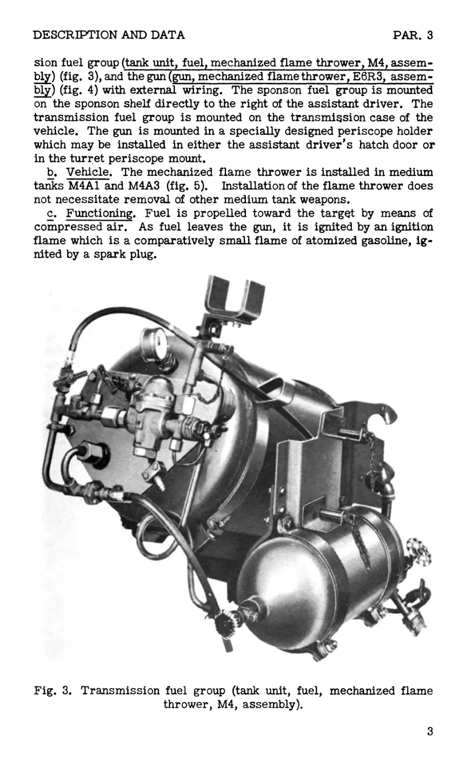
sion fuel group (tank unit, fuel, mechanized flame thrower, M4, assem-
bly) (fig. 3), and the gun (gun, mechanized flamethrower, E6R3, assem-
bly) (fig. 4) with external wiring. The sponson fuel group is mounted
on the sponson shelf directly to the right of the assistant driver. The
transmission fuel group is mounted on the transmission case of the
vehicle. The gun is mounted in a specially designed periscope holder
which may be installed in either the assistant driver’s hatch door or
in the turret periscope mount.
b. Vehicle. The mechanized flame thrower is installed in medium
tanks M4A1 and M4A3 (fig. 5). Installation of the flame thrower does
not necessitate removal of other medium tank weapons.
c. Functioning. Fuel is propelled toward the target by means of
compressed air. As fuel leaves the gun, it is ignited by an ignition
flame which is a comparatively small flame of atomized gasoline, ig-
nited by a spark plug.
Fig. 3. Transmission fuel group (tank unit, fuel, mechanized flame
thrower, M4, assembly).
3
PAR. 3
INTRODUCTION
d. Ranges. (1) Most effective range. When flame thrower is fired
point blank, accuracy is assured, and almost all the fuel is effective as
little or none is burned while passing through the air to the target.
(2) Other effective ranges. Use of thickened fuel gives a maxi-
mum effective range of 40 to 60yards. Use of liquid fuel gives a maxi-
mum effective range of 20 to 30 yards. These distances vary according
to thickness of fuel, direction and velocity of wind, and presence of trees
or underbrush.
(3) Ineffective range. Burning fuel may travel much farther than
ranges given in (2) above, but the fuel is generally ineffective to per-
Fig. 4. Gun (gun, mechanized flame thrower, E6R3, assembly).
4
DESCRIPTION AND DATA
PARS. 3-4
sonnel within pillboxes and nonflammable fortifications, because it
lacks force and volume, falls at too steep an angle of descent, and can
seldom be aimed accurately.
e. Bursts. Flame throwers are generally fired in short bursts of
2 or'more seconds each against one or more specific targets or por-
tions of a target. Keep in mind the limited firing time of the flame
thrower. Several short bursts are usually more effective than one
continuous longer burst.
4. IDENTIFICATION INFORMATION.
Three serial, model, and lot numbers are required for records con-
cerning the components of M3-4-E6R3 mechanized f 1 a m e thrower
Fig. 5. Placement
of mechanized
flame thrower M3-
4-E6R3 in medium
tank. (Insert
shows flame gun
installed in assist-
ant driver’s door.)
5
PARS. 4-5
INTRODUCTION
materiel. They are the numbers of the sponson fuel group (М3), the
transmission fuel group (M4), and the gun (E6R3).
a. Sponson fuel group. A name plate, showing identification infor-
mation, is fastened to the pressure line plate.
b. Transmission fuel group. A name plate, showing identification
information, is fastened to the pressure line plate.
c. Gun. Identification information appears on a name plate fastened
to the front of the gun housing.
5. TABULATED DATA.
All data are approximate.
a. Weights.
Pounds
Flame gun (without external wiring)................... 28
Flame gun (with external wiring)...................... 33
Sponson fuel group (empty)........................... 295
Sponson fuel group (filled with fuel)................ 455
Transmission fuel group (empty)...................... 365
Transmission fuel group (filled with fuel)........... 525
M3-4-E6R3 mechanized flame thrower (empty) . . . 693
M3-4-E6R3 mechanized flame thrower (filled with
fuel)............................................. 1,013
b. Dimensions.
Inches
Baseplate of sponson fuel group.................16 by 33
Maximum height of sponson fuel group.............. 22-1/2
Length of fuel container.......................... 31-1/2
Outside diameter of fuel container................ 16-3/4
Length of pressure container.......................... 23
Outside diameter of pressure container............. 9-5/8
Flame gun length (less gun hose)...................... 23
Gun hose length....................................... 66
Flame shield length............................... 11-1/2
c. Capacity.
(1) Fuel.
Fuel containers (transmission and sponson
groups)...................................25 gallons each
(2) Gasoline.
Gasoline reservoir .............................1-1/4 pint
(3) Electricity (low tension).
Ignition system................................. 12 volts
(4) Pressure.
Pounds per square inch
Pressure container........................ 1,800 to 2,100
Fuel container .............................. 370 to 380
Ignition gasoline reservoir..................... 15 to 30
d. Performance.
Range (maximum) using liquid fuel......... 20 to 30 yards
6
DESCRIPTION AND DATA
PARS. 5-6
Range (maximum) using thickened fuel.... 40 to 60 yards
Elevation (maximum)........................... 24 degrees
Depression (maximum).......................... 20 degrees
Right traverse (from assistant driver’s door)
(maximum)...................................... 90 degrees
Left traverse (from assistant driver’s door)
(maximum)...................................... 45 degrees
Bursts (continuous stream from each fuel container)
5/16-inch nozzle............................... 35 seconds
3/8-inch nozzle............................. 25 seconds
7/16-inch nozzle............................ 20 seconds
Rate of fire (per second)
5/16-inch nozzle.............................. 7/10 gallon
3/8-inch nozzle................................ 1 gallon
7/16-inch nozzle......................... 1-1/5 gallons
Section III. TOOLS, PARTS,
AND ACCESSORIES.
6. ORGANIZATIONAL SPARE PARTS.
A set of organizational spare parts is supplied to the using arm for
field replacement of those parts most likely to become broken, worn,
or otherwise unserviceable. The sets should be kept complete by re-
quisitioning new parts for those used. The parts comprising the set
are listed below. Spare parts provided with each flame thrower are
listed only; this list will not be used in requisitioning. The authority
upon which requisitions are based is Army Service Forces Catalog CW
7-440321 (to be printed).
Quantity
1
1
12
2
1
5
3
6
3
1
3
3
Nomenclature
ATOMIZER, assembly
BARREL, gun, assembly
DIAPHRAGM, safety head, 1/2”
ELECTRODE, ground
FILTER, gasoline reservoir
FUSE, glass tube, 6 amp.
GASKET, barrel coupling
GASKET, flame shield
GASKET, gasoline, distributor plate
GASKET, filter, gasoline reservoir
GASKET, discharge valve, lower
GASKET, discharge valve, upper
7
PARS. 6-7
INTRODUCTION
3 1 1 8 GASKET, valve block NOZZLE, fuel, 5/16” NOZZLE, fuel, 7/16” NUT, lock, S., stainless 1/4” - 20NC (for gasoline housing studs)
12 NUT, mach. screw, hex.,S., (cadmiumplated) No. 8-32NC (for coil cap studs)
4 PACKING, O-ring, 3/8” I. D. x 9/16” 0. D. x 3/32” thick (for discharge valve plunger, atomizer, and clean-out valves)
1 PACKING, O-ring, 1-1/8” 0. D. x 7/8” I. D. x 1/8” thick (for plunger piston)
1 6 6 PERISCOPE PIN, eyebolt release SCREW, cap, socket head, S., (cadmium plated) No. 10-32NC x 3/4” (for flame shield)
4 SCREW, set, socket head, cup pt., S., (phos- phate coating) No. 8-32NC x 1/4” (for at- omizer attachment)
2 SPARK PLUG, ignition, assembly (with front and rear gaskets and terminal stud)
6 1 2 STUD, coil cap (slotted) SWITCH, ignition, assembly SPRING, valve (for atomizer and clean-out valve)
2 VALVE, atomizer and c le an - out, gun, assembly
5 6 6 WASHER, union, 1/4" (synthetic rubber) WASHER, union, 3/8" (synthetic rubber) WASHER, union, 1/4" 0. D. tubing (synthetic rubber)
2 12 WASHER, coupling WASHER, lock, reg., S., (cadmium plated) No. 8 (for coil cap studs)
8 WASHER, plain, SAE std., S., (cadmium plated), 1/4" (for gasoline housing studs)
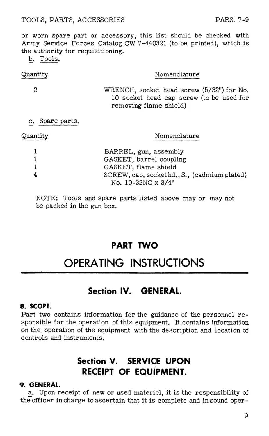
7. TOOLS AND SPARE PARTS.
a. General. Tools include equipment required for cleaning and
preservation of the flame thrower and for such assembling and disas-
sembling as the using arm is authorized to perform. Spare parts fur-
nished are those required for first echelon maintenance. Tools and
spare parts should not be used for purposes other than those prescribed
and should be properly stored when not in use. Those tools and acces-
sories issued for organizational maintenance are listed in section ХП.
The tools and spare parts listed in b and c below are to be kept in the
vehicle at all times for first echelon maintenance of the M3-4-E6R3
flame thrower. If it becomes necessary to replace a broken, missing,
8
TOOLS, PARTS, ACCESSORIES PARS. 7-9
or worn spare part or accessory, this list should be checked with
Army Service Forces Catalog CW 7-440321 (to be printed), which is
the authority for requisitioning.
b. Tools.
Quantity Nomenclature
2 WRENCH, socket head screw (5/32”) for No.
10 socket head cap screw (to be used for
removing flame shield)
c. Spare parts.
Quantity Nomenclature
1 BARREL, gun, assembly
1 GASKET, barrel coupling
1 GASKET, flame shield
4 SCREW, cap, socket hd., S., (cadmium plated)
No. 10-32NC x 3/4”
NOTE: Tools and spare parts listed above may or may not
be packed in the gun box.
PART TWO
OPERATING INSTRUCTIONS
Section IV. GENERAL.
8. SCOPE.
Part two contains information for the guidance of the personnel re-
sponsible for the operation of this equipment. It contains information
on the operation of the equipment with the description and location of
controls and instruments.
Section V. SERVICE UPON
RECEIPT OF EQUIPMENT.
9. GENERAL.
a. Upon receipt of new or used materiel, it is the responsibility of
the officer in charge to ascertain that it is complete and in sound oper-
9
PARS. 9-12
OPERATING INSTRUCTIONS
ating condition. A record should be made of missing parts or of mal-
functions. Such conditions should be corrected as quickly as possible.
b. Attention should be given to small and minor parts, as these are
likely to become lost and may seriously affect the proper functioning
of the materiel.
c. The materiel should be cleaned and prepared for service in ac-
cordance with instructions given in paragraphs 11 through 23. The ma-
teriel should be lubricated in accordance with section XIII.
10. TOOLS AND EQUIPMENT NEEDED FOR INSTALLATION.
The following tools and equipment are required to prepare the weapon
for installation and to install it in medium tanks M4A1 and M4A3:
Portable welding and cutting apparatus
14-inch pipe wrench
15-inch adjustable end wrench
8-inch adjustable end wrench
4-inch adjustable end wrench
Large screw driver (10-inch blade)
Medium screw driver (6-inch blade)
Small screw driver (4-inch blade)
Offset screw driver
Center punch
Ball peen hammer
Cold chisel
Pair of pliers
1/2-inch rope, 15 feet in length (chain or cable may
be used instead)
11. PREPARATION OF VEHICLE FOR INSTALLATION.
a. To install the sponson fuel group, remove ammunition racks, am-
munition, and spare parts box from sponson shelf on right of assistant
driver by unbolting orusing cutting torch. Sponson shelf should be flat
and smooth to receive baseplate of sponson fuel group (fig. 6).
b. For installation of transmission fuel group, remove ventilator fan,
chart table, compass, and other accessories located over transmission
case of vehicle. Place these items in another appropriate space. On
some vehicles, it may be necessary to remove racks containing spare
periscopes and carrier which holds cal. .30 ammunition box. After in-
stallation of baseplate of transmission fuel group, relocate carrier on
hull to left of ball mount.
c. On medium tank M4A3, a portable 4-pound fire extinguisher is
located in front of assistant driver’s seat. Remove the extinguisher
and the bracket; relocate in a convenient place.
12. PREPARATION OF SPONSON FUEL GROUP FOR INSTALLATION.
Perform the following steps to prepare the sponson fuel group for in-
stallation in the vehicle:
10
SERVICE, RECEIPT OF EQUIPMENT
PAR. 12
Fig. 6. Right sponson shelf after clearing and prior to installation
of fuel group.
a. Dismantle packing box. (1) Remove packing box lid and lift out
the boxes containing gun, tools, organizational spare parts, and pres-
sure container relocating equipment.
(2) Knock out sides and ends of packing box. Do not remove fuel
group from bottom of box (fig. 7).
(3) Place box lid (inner side up) on the ground near bottom of box.
(4) Lay all parts and assemblies on the box lid as they are re-
moved from the sponson fuel group.
(5) Remove rust-preventive materials from sponson fuel group.
b. Disassemble parts and assemblies from sponson fuel group. On
vehicles with a single turret hatch without the vision cupola, it is neces-
sary to remove only the pressure container, pressure container straps,
discharge hose, and bleed hose before installation in the vehicle. On
all other models, follow complete procedure below:
(1) Loosen nut which connects pressure container to loop (fig. 7).
(2) Loosen nut connecting loop to pressure cut-off valve.
11
PAR. 12
OPERATING INSTRUCTIONS
pressure
CONTAINER
LOOP
PRESSURE
CUT-OFF
VALVE
FUEL
CONTAINER
PRESSURE
CONTAINER VALVE
PRESSURE
CONTAINER STRAPS
BLEED VALVE
BLEED
BOTTOM OF
LOW PRESSURE
BLOWOFF VALVE
FUEL OUTLET
SAFETY HEAD
PIPING
PACKING BOX
Fig. 7. Sponson fuel group ready for disassembly prior to installation.
BASEPLATE
(3) Remove the jam nut and the nut from each pressure container
strap. Do not push bolts entirely out of holes.
(4) Attach thread protector cap (fig. 8) to pressure container valve
outlet.
(5) Remove pressure container (fig. 9) from pressure container
straps by sliding toward pressure line plate.
(6) Loosen hex nut which connects pressure line to fuel container.
(7) Disconnect bleed hose union at bleed valve, using a wrench on
hex nut of union.
THREAD PROTECTOR CAP
FOR FUEL OUTLET PIPING
THREAD PROTECTOR CAP
FOR PRESSURE INLET
OF FUEL CONTAINER
THREAD PROTECTOR CAP HALF UNION PROTECTOR
FOR PRESSURE CONTAINER VALVE FOR FUEL CONTAINER OUTLET
Fig. 8. Thread protector caps and half union protector.
12
SERVICE, RECEIPT OF EQUIPMENT
PAR. 12
FUEL CONTAINER
Fig. 9. Pressure container removed from fuel container.
(8) Disconnect discharge hose from safety head by applying wrench
to hex nut of union.
(9) A synthetic rubber washer separates the two metal surfaces in
seat of union between fuel container and pressure line. Make certain
this washer is present. Using wrench, remove the three studbolts and
the lock washers which hold pressure line plate to fuel container. Re-
move pressure line plate (fig. 10). With synthetic rubber washer in
position, screw thread protector cap (fig. 8) on pressure inlet threads
of fuel container.
(10) Remove fuel line clamp from fuel outlet piping by unscrewing
two screws with screw driver.
(11) Using two wrenches, hold the back wrench steady and pull front
wrench clockwise to loosen hex nut on union between fuel container and
fuel outlet piping. Attach thread protector to outlet pipe (fig. 8). At-
Fig. 10. Pressure container, loop, pressure line plate, bleed hose,
and discharge hose removed from sponson fuel group.
13
PAR. 12
OPERATING INSTRUCTIONS
tach halfunion protector to fuel outlet (fig. 8). Tighten unionnut to pro-
tect seat of union.
(12) Remove the jam nut and the nut from the two front fuel con-
tainer straps.
(13) Remove the four nuts and the two bolts which connect link to
the two back fuel container straps. Do not disconnect other bolts on
link.
(14) Lift off front fuel container straps and pressure container
straps as units (fig. 11). Do not disassemble them.
(15) Remove the low pressure gage from fuel container.
Fig. 11. Front fuel container straps and pressure container straps
removed from sponson fuel group.
Fig. 12. Fuel container removed, showing back fuel container straps
on baseplate of sponson fuel group.
Fig. 13. Sponson fuel group disassembled and ready for installation.
14
SERVICE, RECEIPT OF EQUIPMENT
PARS. 12-13
(16) Lift out fuel container (fig. 12).
(17) Remove the four nuts, bolts, and lock washers which connect
back fuel container straps to baseplate and lift off back fuel container
straps (fig. 13).
(18) Remove the two bolts at each end of base bracket. Lift base-
plate from bottom of packing box.
13. MOUNTING OF SPONSON FUEL GROUP.
Four men are required to mount and install the sponson fuel group.
One man sits in assistant driver’s seat, one stays in turret until fuel
container is passed through turret, and two men workoutside the vehi-
cle. To provide unobstructed views of the operations, figures in this
section show mounting on a mock-up sponson shelf. Four men work to-
gether to perform the following installations:
a. Baseplate (fig. 14). (1) On some models of medium tanks, lift
Fig. 14. Baseplate in position on mock-up sponson shelf.
Fig. 15. Back fuel container straps bolted on baseplate
of sponson fuel group.
15
PAR. 13
OPERATING INSTRUCTIONS
baseplate, with base brackets attached, through assistant driver’s
hatch. On other models of medium tanks, lift baseplate and brackets
through turret hatch. On all models, rotate turret so opening in turret
basket is directly behind assistant driver’s seat.
(2) Slide baseplate and brackets onto right sponson shelf, at right
of assistant driver’s position. Remove the two stud bolts from front
of baseplate. The baseplate must be alined with vertical side wall of
vehicle. Do not weld or bolt baseplate to sponson shelf at this time.
b. Back fuel container straps. (1) Place the two back fuel container
straps in position.
(2) Secure straps by two bolts, two lock washers, and two nuts
(fig. 15).
c. Fuel container. (1) Attach rope to handle of fuel container and
hoist the container to top of turret. Use care to protect fuel container
outlet and pressure inlet to fuel container.
(2) With one man in turret to receive fuel container, place fuel
container on floor of turret. Remove rope.
(3) Slide fuel container to opening in turret basket, in back of as-
sistantdriver’s seat. Pass containerto man in assistant driver’s com-
partment, who, in turn, slides container onto baseplate (fig. 16).
(4) Drop the two circular metal pads on bottom of fuel container
into two locating holes in baseplate. The fuel container is now located
so that pressure line plate is forward and fuel container outlet is at
rear and right of assistant driver’s seat. Move fuel group as necessary
on sponson shelf to facilitate installation.
(5) Install the two stud bolts in front of the baseplate.
d. Front fuel container straps and pressure container straps (fig. 17).
pad stud BOLTS PAD
Fig. 16. Fuel container of sponson fuel group on baseplate, prior to
positioning fuel container and stud bolts.
16
SERVICE, RECEIPT OF EQUIPMENT
PAR. 13
Fig. 17. Straps tightened on fuel container of sponson fuel
group. Pressure container straps are not yet tightened. Fuel
outlet piping is installed.
(1) Pass assembled front fuel container straps, pressure container
straps, links, two link bolts, nuts, and washers through assistant driver’s
door.
(2) Place front fuel container straps over fuel container and en-
gage holes in straps over two stud bolts.
(3) Secure links to back fuel container straps by inserting bolts
through each link and each back strap. Tighten in place by means of
two nuts on each bolt.
(4) Secure two front fuel container straps and the fuel container to
baseplate by means of two nuts. Tighten each nut with wrench until
straps are in firm contact with fuel container throughout their lengths.
Use second nuts as lock nuts.
(5) Install low pressure gage on fuel container. '
e. Fuel outlet piping. (1) Pass fuel outlet piping, fuel line clamp,
clamp fillers (shims), and fuel line clamp screws through assistant
driver’s door. Then remove thread protector cap from fuel outlet piping.
(2) Remove half union protector from fuel container outlet.
(3) Aline fuel Outlet piping with fuel line clamp and with fuel out-
let from fuel container. Loosely connect coupling nut of piping to male
threaded connection at rear of fuel container.
17
PAR. 13
OPERATING INSTRUCTIONS
Fig. 18. Clamp fillers being moved into position under fuel line. Clamp
is in position on fuel outlet piping of sponson fuel group.
Fig. 19. Pressure container held‘in place by pressure container straps.
18
SERVICE, RECEIPT OF EQUIPMENT
PAR. 13
(4) Place fuel line clamp over piping. Place clamp fillers (shims)
under piping, alining holes in fillers with those in base bracket. Secure
clamp to base bracket bypassing two screws through clamp and fillers
to the base bracket. By placing front screw through clamp and fillers
first (fig. 18), fillers may be readily moved into position for back screw.
Tighten with screw driver.
(5) Tighten union nut at fuel container outlet with two wrenches.
Figure 17 shows fuel outlet piping installed.
f. Pressure container. (1) Pass pressure container through assis-
tant driver’s door. Slide pressure container through the two pressure
container straps. To ease this operation, fuel group may be shifted on
sponson shelf to obtain clearance. Do not secure pressure container
at this time; allow it to rest in straps (fig. 19). Remove thread pro-
tector cap.
(2) Turnfuel group so that its front end extends slightly over edge
of sponson shelf.
g. Pressure line plate. (1) Pass pressure line plate, three stud
bolts, three washers, loop, and synthetic rubber washer through assis-
tant driver’s door.
(2) Remove thread protector cap from pressure inlet of fuel con-
tainer, making sure synthetic rubber washer is in recessed portion of
pressure inlet union of fuel container (fig. 20).
(3) Insert three stud bolts and three washers in pressure line
plate. Aline bolts with three tapped (internal threaded) bosses of fuel
container. At the same time, aline pressure inlet union and its washer
with coupling on fuel container. Screw all three stud bolts and pressure
inlet union nut handtight. Uniformly tighten the three stud bolts, so
Fig. 20. Placing synthetic rubber washer in recess of fuel container
pressure inlet union.
19
PAR. 13
OPERATING INSTRUCTIONS
that mounting plate is firmly in contact with the three bosses of the
fuel container (fig. 21). Tighten union nut on pressure inlet connection
between pressure line plate and fuel container.
h. Loop. (1) Attach loop to union on top of pressure cut-off valve.
Be sure synthetic rubber washer is in the recess. Make union nut hand-
tight only.
(2) Remove thread protector cap from pressure container valve.
(3) Slide pressure container forward orbackward and rotate it un-
til male connection on loop centers with recess of pressure container
valve.
(4) Carefully screw loop nut on valve thread (fig. 22). Because
threads are fine and easily damaged, care must be taken so that the nut
screws on freely and does not require forcing. Do not tighten with
wrench until next step is completed.
(5) Tighten the two pressure container straps by screwing the four
nuts tightly on the two studs on the straps. Tighten nuts until pressure
container straps are firm and flat against pressure container.
(6) Using wrench, tighten coupling nut which connects loop to pres-
sure container valve.
(7) Tighten, with a wrench, the large hex nut which connects loop
to pressure cut-off valve.
Fig. 21. Pressure line plate bolted on three bosses of fuel container
of sponson fuel group.
20
SERVICE, RECEIPT OF EQUIPMENT
PAR. 13
Fig. 22. Screwing loop to pressure container valve. Exercise special
care not to force and damage the fine threads.
i_. Discharge hose. (1) Pass discharge hose through assistant
driver’s hatch. Screw coupling end of hose to male connection on
safety head.
(2) Pass discharge hose around back of sponson fuel group and al-
low free end of hose to extend beyond rear of fuel container. It is de-
sirable to secure discharge hose to back straps of fuel container, us-
ing heavy cord or covered wire. Be sure a loop at least 6 inches in
diameter is allowed for slack at safety head.
PRESSURE CONTAINER BLEED VALVE
Fig. 23. Sponson fuel group completely assembled.
21
PARS. 13-16
OPERATING INSTRUCTIONS
j_. Bleed hose. Attach bleed hose coupling to male connection on top
of bleed valve. Other end of bleed hose should be connected to blow-
off valve. Tighten with wrench. Fuel and pressure group is now com-
pletely assembled (fig. 23).
14. SECURING SPONSON FUEL GROUP TO SPONSON SHELF.
After mounting as described in paragraph 13 has been completed, the
fuel group may be secured to sponson shelf by either of the following
methods:
a. Using bolts. (1) Slide fuel group against side wall of vehicle, so
that rear of base is flush with side wall of vehicle.
(2) Slide fuel group backward on sponson shelf until pressure con-
tainer touches padding over and in back of assistant driver’s position.
(3) Locate position where the four holes are to be drilled through
sponson shelf to hold baseplate to sponson shelf. Use center punch to
mark location of holes.
(4) Slide fuel group forward and drill two back holes for 1/2-inch
bolts. Slide fuel group backward and sidewise. Drill two front holes.
(5) Slide fuel group so that the four holes in sponson shelf and base
bracket are alined.
(6) Insert in these holes the four 1/2-inch bolts which come in a
cloth bag tied to a brace in sponson fuel group packing box. A man on
outside of vehicle applies a nut and lock washer to each of the four bolts.
He tightens the nuts while the man inside the vehicle holds them with
a wrench.
b. Tack welding. Secure fuel group to sponson shelf by tack welding
the base bracket to sponson shelf. Tack welds may be made around
large holes in the bracket.
15. SECURING FREE END OF DISCHARGE HOSE OF SPONSON FUEL GROUP
TO SPONSON SHELF OF VEHICLE.
a. Drill or burn a hole in sponson shelf 6 inches to rear of base
bracket and as near as practicable to side wall of vehicle.
b. Pass discharge hose through this hole in sponson shelf. Allow
hose to protrude 2 inches outside of vehicle.
c. Make an improvised clamp to hold inside portion of hose in place
on the shelf. Bolt or tack weld clamp to shelf approximately 2 inches
from the hole. Wire the hose to the clamp (fig. 23).
d. Coil excess discharge hose to form a loop. Secure this loop to
one of the back fuel container straps with cord, tape, or covered wire.
Be sure hose is not kinked.
16. RELOCATING PRESSURE CONTAINER.
On someM4 series medium tanks the pressure container of the sponson
fuel group interferes with the traverse of the flame gun. In this case,
the pressure container may be removed together with the two pressure
container straps and relocated on the sponson shelf, in front of the fuel
container (fig. 24). A high pressure line (loop) and two saddle brackets
22
SERVICE, RECEIPT OF EQUIPMENT
PAR. 16
Fig. 24. Pressure container relocated on sponson shelf.
are provided for the relocation of the pressure container. To relocate
pressure container proceed as follows:
a. Remove loop from pressure container valve and pressure cut-off
valve.
b. Remove pressure container and pressure container straps from
fuel container straps.
c. Lay saddle brackets on sponson shelf in front of fuel container.
d. Lay pressure container in saddle brackets.
BLEED VALVE
FUEL CONTAINER STRAPS
BLEED
PRESSURE
CUT-OFF
VALVE
LOOP
DISCHARGE
HEAD
FUEL CONTAINER
CONTAINER STRAPS
CONTAINER VALVE
PRESSURE
CONTAINER
UN RACK
BASEPLATE
BLOW-OFF
VALVE
„ FUEL
OUTLET
PIPING
Fig. 25. Transmission fuel group ready for disassembly.
DISCHARGE
HOSE
23
PARS. 16-17
OPERATING INSTRUCTIONS
Fig. 26. U-bracket, discharge hose, bleed hose, and angle bracket
removed from transmission fuel group.
e. Attach loop provided for relocation of pressure container to pres-
sure cut-off valve and pressure container valve.
f_. Mark location of saddle brackets on sponson shelf.
g. Remove the loop and the pressure container.
h. Weld saddle brackets to sponson shelf.
i_. Reinstall pressure container, loop, and pressure container straps.
Tighten connections with wrench.
17. PREPARATION OF TRANSMISSION FUEL GROUP FOR INSTALLATION.
a. Dismantling packing box. (1) Remove box lid and place on ground
(inner side up) near box.
(2) Remove sides and ends of box, leaving fuel group on bottom of
box (fig. 25).
(3) Lay all parts and assemblies on box lid as they are removed
from the transmission fuel group.
(4) Remove rust-preventive materials from transmission fuel
group.
b. Disassembly of parts and assemblies from transmission fuel
group" (1) Remove U-bracket and angle bracket, both of which are
bolted to a board.
(2) Disconnect bleed hose by unscrewing hex nuts of hose from
blow-off valve and bleed valve. Disconnect discharge hose by unscrewing
hex nut of hose from low pressure safety head (fig. 26).
(3) Remove gun rack by unscrewing the four nuts, removing bolts,
and lifting out rack.
(4) Remove loop, using adjustable wrench on union nut at pressure
container valve and on pressure cut-off valve. Make sure synthetic rub-
ber washer of coupling is kept with loop.
(5) Remove the front left pressure container strap by unscrewing
24
SERVICE, RECEIPT OF EQUIPMENT
PARS. 17-18
Fig. 27. Transmission fuel group with gun rack, loop, left front pres-
sure container strap, and pressure container removed.
the two nuts at the bottom and the two nuts at the top.
(6) Remove two nuts from bottom of right front pressure container
strap. Loosen two nuts at top of right front pressure container strap.
Remove pressure container by sliding toward pressure line plate (fig.
27).
(7) Unscrew the two screws onfuel line clamp with screw driver.
(8) Disconnect union at fuel container outlet with one wrench on the
nut and other wrench on hex of union, turning clockwise when facing the
equipment. Attach half union protector to fuel outlet of fuel container.
Screw thread protector cap on fuel outlet piping. Lift off fuel outlet
piping and the clamp.
(9) Disconnect union between fuel container and pressure line.
(10) Unscrew the three stud bolts which hold pressure line plate
to fuel container. Remove plate, bolts, and lock washers (fig. 28). A
synthetic rubber washer is located at this connection. With synthetic
rubber washer in place on inlet, screw thread protector cap on union
of fuel container pressure inlet.
(11) Remove back pressure container strap assembly by removidg
the four bolts (fig. 29).
(12) Remove low pressure gage from fuel container.
(13) Remove the two fuel container straps by looseningthe two nuts
at each end of the straps, but do not remove stud bolts.
(14) Lift fuel container from baseplate (fig. 30).
(15) Remove baseplate by unbolting the two bolts holding base to
wooden skid of packing box.
18. MOUNTING OF TRANSMISSION FUEL GROUP.
Five men are required to mount and install the transmission fuel group.
One man is located in the driver’s seat, another in assistant driver’s
position, and a third in the turret. Two men remain outside the vehicle.
To provide unobstructed views of the operations, figures in this sec-
25
PAR. 18
OPERATING INSTRUCTIONS
Fig. 28. Transmission fuel group with fuel outlet piping, pressure line
plate, and right front fuel container strap removed.
Fig. 29. Back pressure container strap assembly removed.
Fig. 30. Fuel container and straps removed from baseplate.
26
SERVICE, RECEIPT OF EQUIPMENT
PAR. 18
Fig. 31. Transmission case, showing bolt holes where transmission
fuel group baseplate is to be mounted.
tion show installation on a mock-up transmission case. The five men
work together to perform the following installations:
a. Baseplate. (1) Pass baseplate through driver’s door to man in
driver’s seat.
(2) Place baseplate on transmission case so that slotted holes in
baseplate are over the two holes in the transmission case (fig. 31). In-
clined part of baseplate should face turret.
(3) Place bolts through slotted holes in baseplate (fig. 32). Make
bolts handtight only. (Do not tighten with wrenches at this time.)
b. Fuel container. (1) Pass fuel container through turret hatch by
means of rope attached to handle of fuel container.
(2) Slide container across floor of turret, making sure container
does not strike any hard objects.
(3) Disconnect rope.
(4) Pass fuel container through opening in back of assistant driver’s
position and slide it onto baseplate. Handle must be to the front, and
pressure inlet to the rear.
(5) Rotate container until the two circular pads on sides of con-
tainer engage corresponding holes in baseplate.
c. Fuel container straps. (1) Slide both fuel container straps over
fuel container. Front strap is the plain strap; rear strap has a bracket
and projection with a threaded hole through it.
(2) Line up one end of front strap so hole in strap fits over bolt
on baseplate. Place nut on bolt and turn two or three times until it is
engaged.
(3) Using 8-inch adjustable end wrench as a lever, pulldown other
end of front strap until bolt from baseplate is through hole in end of
strap. Place nut on bolt and engage threads.
(4) With one man on each side of fuel group, tighten nuts on both
27
PAR. 18
OPERATING INSTRUCTIONS
Fig. 32. Baseplate viewed from assistant driver’s seat (above) and
driver’s seat (below).
ends of straps simultaneously until strap is flat against fuel container.
(5) Place a second nut over each of first two nuts and tighten them.
(6) Repeat procedures (2) through (5) above with rear fuel con-
tainer strap.
(7) Install low pressure gage on fuel container.
d. Pressure line plate. (1) Replace synthetic rubber washer in re-
cess of male fitting of fuel container pressure inlet union.
(2) Hold pressure line plate at end of fuel container. Insert three
stud bolts through holes in plate and engage them in threaded bosses
in order to hold pressure line plate to fuel container (fig. 33). Check
alinement of pressure line union with half union on fuel container. Nut
must engage threads on half union fully without necessity of forcing.
(3) Tighten all three stud bolts uniformly.
(4) Tighten nut on pressure line union.
28
SERVICE, RECEIPT OF EQUIPMENT
PAR. 18
Fig. 33. Fuel container, fuel container straps, and pressure line plate
installed on transmission fuel group baseplate.
(5) Place synthetic rubber washer in recess of half union on top
of pressure cut-off valve.
(6) Attach high pressure line assembly (loop) to pressure cut-off
valve by engaging nut of half union on assembly with male connection of
half union of pressure cut-off valve. Make handtight.
e. Back pressure container straps and right front pressure container
strap. Connect back pressure container strap and right front pressure
container strap by inserting four stud bolts through the four holes in
back pressure container strap assembly and engaging bolts to tapped
holes in the side of the baseplate (fig. 34). Tighten all four stud bolts
uniformly.
f_. Pressure container. (1) Place pressure container on back pres-
sure container straps and hold container in place by inserting bolt
through right front pressure container strap. Remove thread protector
cap from pressure container valve. Aline outlet of pressure container
valve with connection on end of loop. Connect loop to pressure con-
tainer valve (fig. 35). Install left front pressure container strap.
Tighten both ends of each strap evenly so gaps between “ears” at ends
of each front and each back strap are equal; otherwise, there will be
insufficient space on the top strap to insert gun rack.
(2) Tighten nut on end of loop adjacent to pressure container.
Tighten union nut at pressure cut-off valve.
29
PAR. 18
OPERATING INSTRUCTIONS
Fig. 34. Back pressure container straps and right front pressure
container strap ready to receive pressure container.
g. Fuel outlet piping. (1) Remove half union protector from fuel
container outlet and remove thread protector cap from fuel outlet pip-
ing. Attach fuel outlet piping to fuel container (fig. 36) by engaging nut
on half union at fuel container with male half angle union at fuel outlet
piping.
(2) Attachfuel line clamp and clamp fillers (shims) to angle bracket
(bolted to baseplate) by inserting screws through holes in clamp, fillers,
and tapped holes in block on bracket. Tighten screws with screw driver.
(3) Tighten union between fuel outlet piping and fuel container,
using wrench on nut and on half union at fuel container.
h. Gun rack. Place gun rack on top of pressure container. Insert
four bolts (with flat washers) through the four holes in gun rack and
ends of back pressure container straps. Insert flat washer, lock wash-
er, and nut over exposed end of each bolt and tighten uniformly.
i_. Angle bracket. Attach angle bracket to back fuel strap on top of
fuel container by sliding slot of bracket over bolt in “ear” at end of
fuel container strap. Bolt should be as high as possible in slot.
j_ . Bleed hose. (1) Screw nut on end of bleed hose to the fitting at
top of bleed valve.
(2 ) Screw nut on other end of bleed hose to fitting on blow-off valve .
Tighten with wrench.
30
SERVICE, RECEIPT OF EQUIPMENT PARS. 18-20
Fig. 35. Pressure container, right front pressure container strap,
and loop installed on transmission fuel group.
k. Discharge hose. Screw one end of safety head discharge hose on
low pressure safety head. Tighten with wrench. Transmission fuel
group is now completely assembled (fig. 37).
19. ADJUSTING POSITION OF TRANSMISSION FUEL GROUP IN VEHICLE.
Slotted holes in the baseplate are provided so that the transmission fuel
group can be slid forward or backward on transmission case in order
for piping and controls on pressure line plate to clear projections on
turret. After fuel group has been mounted on transmission case:
a. Rotate turret slowly to check clearances between projections on
turret and pressure lines. Slide fuel group as required to establish
necessary clearances.
b. After clearances have been established, tighten the two stud bolts
(between transmission case and baseplate), using wrench.
20. INSTALLING U-BRACKET.
In some vehicles it may be necessary to remove blower system from
roof in order to install transmission group. In these instances, the
angle bracket may be directly under the hole from which blower sys-
tem was removed. In this instance, weld a flat piece of sturdy metal
across this hole and spot weld U-bracket to this piece.
31
PARS. 20-21
OPERATING INSTRUCTIONS
Fig. 36. Pressure system and fuel outlet piping installed on trans-
mission fuel group.
a. Measure distances between roof of vehicle and top of the angle
bracket at highest and lowest points.
b. Cut U-bracket with cutting torch so that U-bracket can be spot
welded to roof of vehicle and can be attached to the angle bracket. In
this way, fuel group is secured both to transmission case and roof of
vehicle, eliminating swaying or pitching motion of fuel group.
c. Check to see that fit of U-bracket is correct.
d. Connect U-bracket to angle bracket, using two stud bolts and flat
washers. Do not tighten.
e. Shift U-bracket backward and forward. Raise angle bracket until
contact is made with roof of vehicle. Tighten the two bolts on U-bracket
and the bolt on the angle bracket.
f_. Tack weld U-bracket to roof of vehicle at four or more points on
each side of U-bracket (fig. 38).
21. SECURING FREE END OF DISCHARGE HOSE OF TRANSMISSION FUEL
GROUP TO SPONSON SHELF OF VEHICLE.
a. Drill or burn hole through right sponson shelf adjacent to hole
32
SERVICE, RECEIPT OF EQUIPMENT
PAR. 21
Fig. 37. Transmission fuel group completely assembled.
Fig. 38. Transmission fuel group installed,and U-bracket welded to
roof of vehicle.
33
PARS. 21-23
OPERATING INSTRUCTIONS
made for discharge hose of sponson fuel group.
b. Pass discharge hose around rear of assistant driver’s seat and
through hole in sponson shelf.
c. Secure to sponson shelf as described in paragraph 15.
22. ADJUSTING PRESSURE REGULATORS.
Pressure regulators of both the fuel groups are shipped without pres-
sure on the dome. Adjust pressure regulators as described in section
xvm.
23. INSTALLING GUN GROUP.
Remove gun group and external wiring from gun chest. Remove rust-
preventive materials, clean, and lubricate (sec. XIII).
a. External wiring. Connect external wiring of flame gun to vehicle
as follows:
(1) Remove two of the stud bolts which are in front of the assis-
tant driver’s side of the vehicle, located just below and to the right of
the ball mount socket. The two bolts to be removed are approximately
12 inches above the tank floor. These bolts have the same centers as
the fuse box bracket.
Fig. 39. Switch fuse box installed on hull.
34
SERVICE, RECEIPT OF EQUIPMENT
PAR. 23
(2) Mount switch fuse box over the two holes. Replace and tighten
the two bolts with a wrench (fig. 39).
NOTE: If desired, the box can be mounted on the front slope
of the vehicle in front of the assistant driver. It is secured to
the slope by spot welding. The location, however, must be
such that the box does not interfere with the traverse, eleva-
tion, and depression of the gun.
(3) Lay shielded wire lead around front of interior of vehicle, past
the driver’s position and the radio, to the battery or master switch box
of the vehicle. Secure lead in this position by attaching clips to the
hull and to master switch box if terminal of lead is to be attached to
12-volt switch.
(4) Connect battery lead to 12-volt terminal of battery or to 12-
volt switch in master switch box.
(5) Gun lead wire is not connected to gun until the gun is installed.
(6) Check to see if fuse is properly installed in switch fuse box.
b. Barrel assembly. (1) Preparatory procedure for installation of
barrel assembly.
Fig. 40. Traverse limit stop plate and pin installed.
35
PAR. 23
OPERATING INSTRUCTIONS
(a) Remove standard periscope holder by unscrewing the screws
from the two split-plates on the underside of the mount. (Some peri-
scope mounts may have a ring which secures the periscope holder to
the assistant driver’s door. This ring must be removed.)
(b) Install specially designed periscope holder (included with
each flame thrower), without the periscope, into assistant driver’s
door, by reversing the procedure for removal of the standard holder.
(c) Attach the traverse limit stop plate to the split-plate with
the two cap screws supplied. Mount the traverse limit stop pin to the
periscope mounting ring (fig. 40). If mount has no bolt ring, weld pin
to underside of hatch door. The pin should be located to give a traverse
of 45 degrees left of the vehicle front (fig. 41).
(d) Attach depression limit stop plate to the left side of peri-
scope holder (side opposite vertical lock screw) by inserting the two
cap screws in the existing holes.
(e) Separate barrel assembly from gun control assembly in the
following manner (fig. 42):
--Loosen barrel coupling tightening knob and raise it so that
eyebolt is clear of locking grip on coupling bracket assembly.
—With the eyebolt clear of the locking grip, pull back and
downward on mounting bracket so that hooks on both sides
Fig. 41. Traverse limit diagram.
36
SERVICE, RECEIPT OF EQUIPMENT
PAR. 23
of the bracket assembly disengage the barrel coupling pins.
--Lift barrel assembly from gun control assembly.
(2) Installation pf barrel assembly. Figure 43 shows the series of
operations used to install the barrel assembly.
c. Periscope. To install periscope, turn knurled knob counterclock-
wise as far as it will go. (Do not attempt to remove knob.) Follow op-
erations shown in figure 44 for installation sequence.
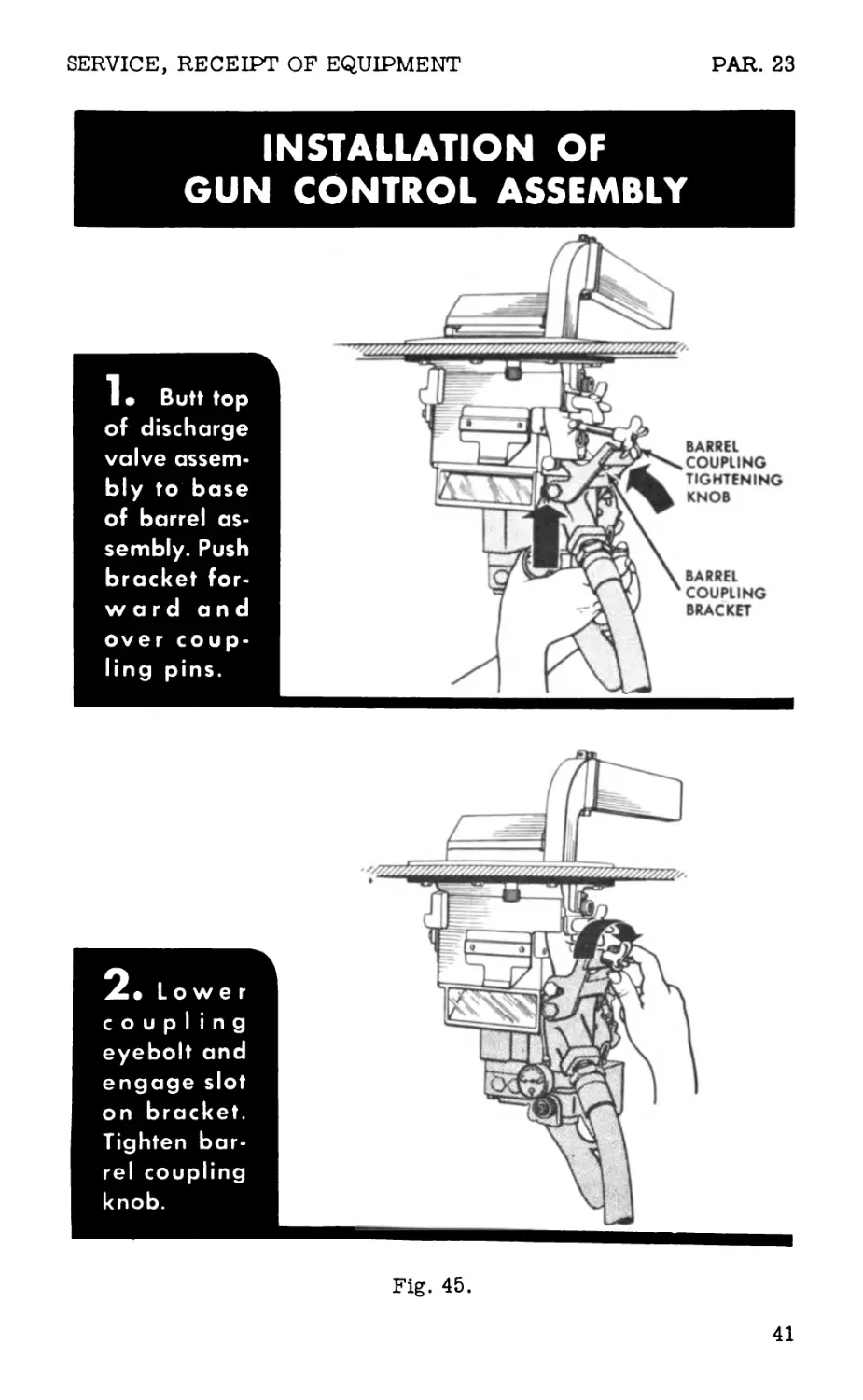
d. Gun control group. Connect gun control group to barrel assembly
by procedure given in figure 45.
e. Gun hose. (1) To install hose in gun, screw hose into discharge
Fig. 42. Gun showing components for disconnecting and connecting
barrel assembly to gun control assembly.
37
PAR. 23
OPERATING INSTRUCTIONS
barrel assembly
MO“nSpecio»Y Oe^ned
PenscoP® Holder
!• Rotate
periscope
holder so
that vertical
locking screw
is to right
and peri*
scope holder
is at a 45*de*
gree angle
to front of
vehicle.
2« Insert
flame shield
through peri-
scope holder
as far as
possible.
Fig. 43.
38
SERVICE, RECEIPT OF EQUIPMENT
PAR. 23
Manipu-
late assem-
bly so that
barrel elbow
is vertical
and flame
shield is
horizontal.
4» Rotate
barrel as-
sembly to
left so that
barrel lock-
ing stud is
alined with
hole in bush-
ing on peri-
scope holder.
Manipu-
late assem-
bly so that
stud passes
through
bushing.
Screw on
barrel lock-
i n g knob.
Fig. 43.
39
PAR. 23
OPERATING INSTRUCTIONS
INSTALLATION OF PERISCOPE
1. Slide
periscope in-
to periscope
holder as far
as possible.
IITI
2» Rotate
periscope to
left; see that
knurled knob
slot. Tighten
knob hand-
tight.
SLOT
KNURLED
KNOB
Fig. 44.
40
SERVICE, RECEIPT OF EQUIPMENT
PAR. 23
INSTALLATION OF
GUN CONTROL ASSEMBLY
• Butt top
of discharge
valve assem-
bly to base
of barrel as-
sembly. Push
bracket for-
w a r d and
over coup-
ling pins.
2» Lower
coupling
eyebolt and
engage slot
on bracket.
Tighten bar-
rel coupling
knob.
BARREL
COUPLING
TIGHTENING
KNOB
BARREL
COUPLING
BRACKET
Fig. 45.
41
PAR. 23
OPERATING INSTRUCTIONS
Fig. 46. Inserting gun hose nipple in coupling. (Synthetic washer
must be in coupling.)
Fig. 47. Closing two cams so they lie flat against coupling body.
Fig. 48. Closing coupling lock until it covers ends of cams.
42
SERVICE, RECEIPT OF EQUIPMENT PARS. 23-24
valve body by hand. Using two wrenches, one on squared end of valve
and one on hex end of hose, tighten connection.
NOTE: Remove hose from gun only when necessary for main-
tenance.
(2) To attach hose to fuel outlet piping of either fuel group:
- -Check to make sure coupling washer is in place in coupling
body. Be sure washer is not damaged or swollen.
- -Open coupling lock and pull out the two cams from the coupling.
- -Insert unthreaded hose nipple in coupling as far as possible
(fig. 46).
- -Close cams so that they lie flat against coupling body (fig. 47).
- -Close coupling lock (fig. 48), being sure to push it all the way
up, so that it covers ends of both cams.
— Test tightness of coupling by attempting to pull hose from
coupling.
1. Air hose. (1) To install hose on gun, snap hose socket onto the
hose plug, which is located on the rear of the valve block.
(2) To attach hose to the plug on the air line valve of fuel group,
snap hose socket onto plug of air line valve.
Section VI. CONTROLS AND INSTRUMENTS.
24. FUEL GROUPS.
Controls and instruments of sponson and transmission fuel groups are
identical in operation. They are within reach of assistant driver when
he is seated. Controls and instruments of sponson fuel group (fig. 49)
are at his right; those of the transmission fuel group (fig. 50) are at
his left.
a. Pressure container valve. This valve is mounted at the front end
of the pressure container. When closed, the valve retains high pres-
sure in the pressure container. When opened, it permits charging of
container and allows release of compressed air to the high pressure
line. To open valve, turn handle counterclockwise by hand; to close
valve, turn handle clockwise by hand. Do not use wrench.
b. High pressure line gage. This 0- to 3,000-pound high pressure
gage is located on the pressure line plate. It indicates pounds per
square inch of pressure in the pressure container. Pressure container
valve must be opened before gage indicates pressure in pressure con-
tainer.
43
PAR. 24
OPERATING INSTRUCTIONS
Fig. 49. Controls and instruments of sponson fuel group.
c. Pressure cut-off valve. This valve is connected to the pressure
regulator. When opened, it allows passage of compressed air through
the regulator. When closed, it permits charging of pressure container
without allowing entry of pressure to pressure regulator and fuel con-
tainer. To open valve, turn handle counterclockwise by hand. To close
valve, turn handle clockwise. Do not use wrench.
d. Bleed valve. This valve is located on the pressure line plate be-
tween a tee and bleed hose. During fuel filling operation, with bleed
hose disconnected at blow-off valve, opening of bleed valve permits air
in fuel container to escape, allowing container to fill with fuel. When
fuel runs out of bleed hose, container is filled with fuel.
e. Air line valve. This valve is located on the pressure line plate.
The valve controls the flow of compressed air necessary to operate
the valves of the flame gun and controls the air which blows ignition
gasoline around the stream of flame thrower fuel as the fuel leaves
the nozzle. To open valve, turn handle counterclockwise. To close
valve, turn handle clockwise. Do not use wrench.
£. Blow-off valve. This Valve is located on fuel outlet piping, be-
tween fuel container valve and nipple leading to coupling. Valve is open-
ed to permit remaining fuel under pressure (in gun hose and in fuel out-
let piping beyond fuel container valve) topass through the gun hose and
to be discharged from the gun. To open valve, turn handle counterclock-
wise. To close valve, turn handle clockwise. Do not use wrench.
g. Fuel container valve. This valve is located on the fuel outlet
44
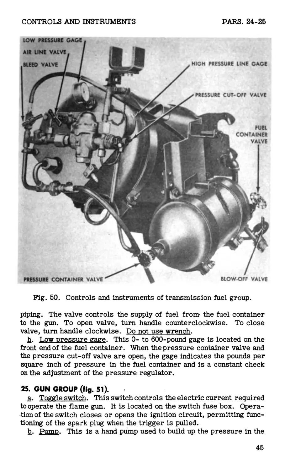
CONTROLS AND INSTRUMENTS
PARS. 24-25
Fig. 50. Controls and instruments of transmission fuel group.
piping. The valve controls the supply of fuel from* the fuel container
to the gun. To open valve, turn handle counterclockwise. To close
valve, turn handle clockwise. Do not use wrench.
h. Low pressure gage. This 0- to 600-pound gage is located on the
front end of the fuel container. When the pressure container valve and
the pressure cut-off valve are open, the gage indicates the pounds per
square inch of pressure in the fuel container and is a constant check
on the adjustment of the pressure regulator.
25. GUN GROUP (fig. 51).
a. Toggle switch. This switch controls the electric current required
to operate the flame gun. It is located on the switch fuse box. Opera-
tion of the switch closes or opens the ignition circuit, permitting func-
tioning of the spark plug when the trigger is pulled.
b. Pump. This is a hand pump used to build up the pressure in the
45
PAR. 25
OPERATING INSTRUCTIONS
Fig. 51. Controls and instrument on the gun.
gasoline container to the operating pressure of 30 pounds per square
inch. It is located on the side of the gasoline reservoir above the coil
cap. To operate, turn pump handle two or three complete turns counter-
clockwise to unlock. Build up pressure by pulling and pushing on the
handle until the gasoline pressure gage indicates 30 pounds per square
inch. When operating pressure is reached, lock pump by pushing handle
forward as far as it can go and then turn handle clockwise two or three
turns. If it is desired to release the pressure in the gasoline reservoir
without firing the gun, unscrew gasoline filler plug just enough to per-
mit the air to escape.
c. Gasoline pressure gage. This gage, screwed into the discharge
valve housing, indicates the air pressure in the gasoline container.
The gage records pressures up to 30 pounds per square inch. To aid
the reading of the gage, the quadrant from 0 to 15 pounds per square
inch is painted red to indicate inadequate operating pressure.
d. Trigger. The trigger, which is located above the trigger guard
controls the operation of the flame gun. Pulling on the trigger operates
the spark plug and simultaneously regulates flow of air, gasoline, and
fuel through the system. The atomized gasoline is ignited by the spark
from the spark plug, thereby producing the ignition flame which in turn
46
OPERATION, USUAL CONDITIONS PARS. 25-26
ignites the flame thrower fuel.
e. Blow-out lever. This manually operated lever is used to blow out
the remaining fuel from the gun upon completion of firing. The lever
projects below the valve housing cover and operates when depressed.
f_. Trigger safety knob. The knob, located above the trigger on the
right side of the valve block, locks the trigger in the “safe” position.
To lock the trigger, turn the knob clockwise as far as it will go. To
unlock the trigger, turn the 'knob in the counterclockwise direction un-
til a click is heard.
g. Air cylinder needle valve. The valve is located on the right side
of the air cylinder above the gun grip and controls the flow of fuel from
the gun hose to the flame gun. To open the valve, turn the valve knob
in a counterclockwise direction. To close, turn knob in clockwise di-
rection.
Section VII. OPERATION
UNDER USUAL CONDITIONS.
26. GENERAL.
Before starting on a mission which may involve use of the flame throw-
er, proceed as follows:
a. Install flame gun. Mountflame gun in periscope holder (par» 23).
b. Perform before-operation service. Perform services described
in paragraph 43.
c. Connect flame gun to fuel group. Connect unthreaded nipple of
gun hose to coupling on fuel outlet piping of the fuel group to be used
first (par. 23).
d. Test fire. Test fire weapon in the following sequence:
(1) Pump 30 pounds pressure into gasoline reservoir.
(2) Open pressure container valve all the way and observe reading
on high pressure line gage. Reading should show pressure of at least
1,800 pounds per square inch.
(3) Open pressure cut-off valve slowly and fully.
(4) Open air line valve fully.
(5) Open fuel container valve fully.
(6) Turn on toggle switch.
(7) Close needle valve on air cylinder of gun.
(8) Be sure trigger is unlocked.
(9) Depress trigger and check ignition flame. Release trigger.
(10) Open needle valve fully.
(11) Depress trigger, which fires the flame thrower. Release
trigger.
47
PARS. 26-30 OPERATING INSTRUCTIONS
(12) Depress manual blow-out lever.
e. Set gun in safe position. After test firing:
(1) Lock trigger in “safe” position by turning trigger safety knob
clockwise as far as it will go.
(2) Turn off toggle switch.
27. OPERATIONS PERFORMED WHEN APPROACHING TARGET.
During approach of vehicle to target, perform following operations:
a. Turn on toggle switch.
b. Check blow-off valve to see that it is fully closed.
c. Grasp gun grip. Do not unlock trigger at this time.
28. SIGHTING AND AIMING.
a. Sighting. There are no sights on the weapon, as all sighting is
done through the periscope.
b. Aiming. In aiming, make allowances for wind deflection. Burning
fuel in flight toward target (because of its low velocity) deflects with
crosswinds.
29. FIRING.
After vehicle has approached as near as possible to the target, and
weapon has been carefully aimed:
a. Unlock trigger by turning trigger safety knob.
b. Pull trigger all the way to the rear; this fires the flame thrower.
c. Using short bursts, adjust fire by traversing, elevating, or de-
pressing until flame is on the target.
d. To cease fire, release trigger.
e. After each burst, depress blow-out lever to clear gun of fuel and
to extinguish flame in flame shield.
CAUTION: Do not attempt to fire unignited bursts as this may
cause fouling of the ignition system.
30. OPERATIONS PERFORMED AFTER FIRING.
a. If almost all fuel has been expended in one of the fuel groups, and
the gun is connected to that unit, carry out following procedure:
(1) Close pressure container valve.
(2) Depress trigger and fire remaining fuel from the fuel container.
(3) Close all remaining valves and locktrigger in “safe” position.
(4) Turn off the toggle switch.
b. If most of the fuel has not been expended, and if gun is not to be
disconnected from fuel group, depress blow-out lever to clear gun,
and lock trigger in “safe” position.
c. After vehicle has completed a mission, close all valves and per-
form all after-operation services prescribed in paragraph 46.
48
OPERATION, AUXILIARY EQUIPMENT
PARS. 31-35
Section VIII. OPERATION
OF AUXILIARY EQUIPMENT.
31. GENERAL.
No auxiliary equipment is used with the M3-4-E6R3 mechanized flame
thrower other than fuel filling equipment and pressure charging equip-
ment as explained in part four of this Technical Manual.
Section IX. OPERATION
UNDER UNUSUAL CONDITIONS.
32. WIND.
Wind is an important factor in effective use of the flame thrower, be-
cause of the low velocity of flaming fuel. Head winds tend to shorten
range and cause poor ignition, because ignition flame is blown away
from fuel as fuel leaves nozzle of gun. Crosswinds tend to deflect and
disperse flame and reduce range. Following winds tend to lengthen the
range and increase the accuracy of the weapon.
WARNING: Do not fire liquid fuels into head winds of more
than 5 miles per hour. Do not fire thickened fuels into head
winds of more than 10 miles per hour. (Head wind speed
limits are based on firing from a stationary vehicle.)
33. EXCESSIVE DUST.
As far as practicable, keep flame thrower free of dust. Do not install
flame gun in periscope holder until just before flame thrower mission.
Clean weapon more frequently under dusty conditions.
34. HEAT.
Hot climate or exposure to sun thins fuel. Thin fuel has shorter range
than thickened fuel; it has a tendency to be largely consumed in air be-
fore reaching the target. If fuel is ineffective, vary the viscosity until
a satisfactory mixture is obtained.
35. COLD.
The weapon may be used at temperatures as low as minus 20° F., and
lubrication requirements are the same as for other temperatures.
49
PARS. 36-38
OPERATING INSTRUCTIONS
36. WET CONDITIONS.
When operating weapon during extremely wet ordamp weather, observe
the following precautions:
a. Fuel. Do not allow water to enter fuel or fuel ingredients.
b. Flame thrower. If gun becomes soaked or submerged in water:
(1) Dry and clean gun thoroughly.
(2) Lubricate (sec. XIII).
(3) Before firing, test spark, ignition flame, and main flame.
Section X. DEMOLITION
TO PREVENT ENEMY USE.
37. GENERAL.
a. Destruction of materiel when subject to capture or abandonment
in the combat zone will be undertaken by the using arm only when, in
the judgment of the military commander concerned, such action is
deemed necessary to keep materiel from reaching enemy hands.
b. Adequate destruction of the flame thrower means damaging it to
such an extent that the enemy cannot restore it to usable condition in
the combat zone either by repair or by cannibalization, and damaging
it so thoroughly as to prevent its study and reproduction. Adequate
destruction requires that:
(1) Enough parts essential to the operation of the flame thrower
be damaged.
(2) Parts must be damaged beyond repair in the combat zone.
(3) The same parts must be destroyed on all materiel, so the
enemy cannot make up one operating unit by assembling parts from
several partly destroyed units.
38. SPECIFIC DEMOLITION PROCEDURES.
a. Flame gun. Strike with ax, sledge, or other heavy instrument to
smash the housing, crush the barrel, and destroy valves and gun grip.
b. Fuel groups. (1) Strike with ax, sledge, or other heavy instru-
ment to smash gages, valves, pressure lines, and pressure regulator.
(2) Fire several small arms bullets through pressure and fuel
containers to render them temporarily useless.
(3) Tie detonator and 1-pound block of TNT or equivalent to pres-
sure container, pressure line plate, and fuel container and detonate.
c. Service kit E9. Smash larger parts with ax, sledge, or other
heavy instrument. Scatter smaller parts.
d. Filling and charging apparatus. (1) Destroy hose, manifold block,
and valves by ax, sledge, or other heavy instrument.
(2) Render large pressure cylinders useless by releasing contents,
50
DEMOLITION
PARS. 38-40
and destroy valves by blows with an ax or sledge.
(3) Stack charged or empty cylinders like cordwood (in groups of
five to a stack) and demolish by detonating four 1/2-pound blocks of
TNT.
e. Fuel. Burn.
L Fuel thickener. Break open cans of thickener; throw their con-
tents into a fire or a body of water.
PART THREE
MAINTENANCE INSTRUCTIONS
Section XI. GENERAL.
39. SCOPE.
Part three contains information for the guidance of personnel of using
organizations responsible for first and second echelon maintenance of
this equipment. It contains information needed for the performance of
the scheduled lubrication and preventive maintenance services, as well
as a description of the major systems and units and their functions in
relation to other components of the equipment.
Section XII. SPECIAL ORGANIZATIONAL
TOOLS AND EQUIPMENT.
40. GENERAL.
The following special organizational tools and equipment are issued
to the using arm for performance of maintenance services, fuel fil-
ling, and pressure charging of the weapon. Authority and all infor-
mation for ordering spare parts are given in Army Service Forces
Catalogs, and these supply catalogs should always be used in requisi-
tioning. Chemical Warfare Service nomenclature given in this manual
is for information and guidance only.
a. The service kit, mechanized flame thrower, E9 is issued for use
with each three flame throwers. Contents of kit are listed below.
51
PAR. 40
MAINTENANCE INSTRUCTIONS
TOOLS
Quantity Nomenclature
1 1 FILE, American Std., mill, second-cut, 10” PLIERS, combination, slip-joint, wire- cutting, 6”
1 1 ROLL, tool (less contents) SCREWDRIVER, common, normal-duty, 6” blade
1 SCREWDRIVER, common, heavy-duty, inte- gral handle, 10” blade
1 SCREWDRIVER, off-set, double-end, 1/4" blade x 4" over-all
1 SCREWDRIVER, off-set, double-end, 3/8" blade x 6" over-all
1 12 TOOL, inserting, control valve WIRE, clean-out, atomizer (No. 2 music wire by 12” long)
2 WRENCH, adjustable, crescent-type, single- end, 4”
1 WRENCH, adjustable, crescent-type, single- end, 8”
1 1 WRENCH, box (5/8” hex.) WRENCH, engineer’s, 15°, single-head, thin, 5/8”
1 2 WRENCH, pipe, adjustable, normal-duty, 14" WRENCH, socket hd. screw, 1/16” hex. (for No. 5 and No. 6 set screws)
2 WRENCH, socket hd. screw, 5/64” hex. (for No. 8 set screw)
2 WRENCH, socket hd. screw, 3/32” hex. (for No. 10 set screw)
2 WRENCH, socket hd. screw, 1/8” hex. (for 1/4” set screw)
4 WRENCH, socket hd. screw, 5/32” hex. (for 5/16” set screw)
2 WRENCH, socket hd. screw, 3/16” hex. (for 3/8” set screw)
2 WRENCH, socket hd. screw, 7/32” hex. (for 7/16” set screw)
1 1 2 WRENCH, socket, spring retainer, 3/4” WRENCH, socket, spring retainer, 1” WRENCH, spanner (for discharge valve plun- ger spring retainer)
2 WRENCH, spanner (for spark plug nut and fuel nozzle)
2 WRENCH, spanner (for discharge valve plun- ger and gasoline housing filter)
52
SPECIAL TOOLS, EQUIPMENT
PARS. 40-41
ACCESSORIES
Quantity Nomenclature
4 3 ADAPTER, pressure regulator CHAMOIS COMPOUND, gasket
1 CONNECTOR, brass, 1/4” - 18 NPTx 9/16” - 18 RH thread
1 COUPLING, brass, 1/4” - 18 NPT x 9/16” - 18 RH thread
1 FUNNEL, tinned iron, 3-5/8” diam. x 5/16” maximum spout size
1 1 FUNNEL, (12” diam.) GAGE, pressure, 0-600 pound, 2-1/2** diam. dial, 1/4” male NPT connection
1 1 1 HOSE, charging line LINE, charging, pressure cylinder, assembly LINE, filling, pressure cylinder, assembly (portable manifold type)
b. The kit, fuel filling, flame thrower, E6 (MIO) is issued for use
in accordance with T/O & E. Contents of the kit and ’instructions for
its use are described in ТВ CW 18. (Technical Bulletins are to be
superseded by appropriate War Department Technical Manuals or
changes to manuals.)
Section XIII. LUBRICATION.
41. LUBRICATION ORDER.
a. War Department Lubrication Order No. 3-U3(fig. 52) prescribes
first and second echelon lubrication maintenance.
b. A lubrication order is issued with each flame thrower and is to
be kept with it at all times. If materiel is received without an order,
requisition an order immediately (FM 21-6).
c. Lubrication instructions on the order are binding on all echelons
of maintenance, and there will be no deviations from these instructions.
53
PAR. 41
MAINTENANCE INSTRUCTIONS
WAR DEPARTMENT LUBRICATION ORDER
1 JUNE 1945
GUN, MECHANIZED FLAME THROWER, E6R3
References: TM 3- 364
Intervals given are based on firing of 10 fuel
charges or less per week. Reduce intervals to
compensate for greater activity. Intervals may
be extended during inactive periods.
Clean parts with SOLVENT, dry cleaning, or
with OIL, fuel, Diesel. Dry before lubricating.
lubricant • Interval
Coupling Locking Pins
PS
Pump Plunger Rod
PS
Leather Cup Washer
(Remove pump plunger and apply 10
drops to cup washer)
PS
Control Levers
PS
Valve Stems
PS
Grip Pivot
PS
Camshaft Bearings
PS
fAIITION DO NOT LUBRICATE
VMUIIVH SAFETY LOCK
Trigger Pivot
PS
Air Cylinder
(S.e Note)
PS
Trigger Link
PS
NOTES
w
W
M
w
w
w
w
w
W
SIDE VIEW
FRONT VIEW
(Dust Cover removed)
AIR CYLINDER—Weekly, unlock grip and with
flame thrower in inverted position apply 10
drops PS to cylinder around the piston.
KEY
LUBRICANTS (All Temperatures) INTERVALS
PS—OIL, lubricating, pre- servative, special W—Weekly M—Monthly
Copy of this Lubrication Order will remain
with the equipment at all timet: instructions
contained therein are mandatory and super-
sede all conflicting lubrication instructions
dated prior to 1 June 1945.
[AG. 300.8 ( 1 June 1945))
By Order of the Secretary of War:
G. C. MARSHALL,
Official: Chief of Staff.
J. A. ULIO,
Major General,
The Adjutant General.
Requisition additional Lubrication Orders in conformance with instructions and lists in FM 21-6.
Fig. 52. Lubrication order (temporary).
54
PREVENTIVE MAINTENANCE
PARS. 42-43
Section XIV. PREVENTIVE
MAINTENANCE SERVICES.
42. GENERAL.
a. Responsibility. Preventive maintenance services as prescribed
by AR 850-15 are a function of using organization echelons of main-
tenance, and their performance is a responsibility of the commanders
of such organizations.
b. Intervals. Preventive maintenance services consist of before-
operation, during-operation, at-halt, after-operation, and weekly ser-
vices.
c. Care. Keep the flame thrower free from dust, dirt, or other for-
eign material; repaint scratched or marred surfaces and keep free of
rust. Use only hand pressure when operating controls of the weapon.
Take care that flame gun is not dropped or allowed to strike against
hard surfaces; such maltreatment may injure valves, ignition spark
plug, or other parts and assemblies. Take all possible precautions to
keep flame gun dry.
43. BEFORE-OPERATION SERVICE.
a. Purpose. Before-operation services are performed by first eche-
lon and are designed primarily as a check to see that the weapon is in
condition to carry out any mission to which it is assigned.
b. Procedures. Before-operation services include inspection (ac-
cording to the procedure described below) and correction, or report-
ing of any deficiencies.
(1) Tampering and damage. Examine entire flame thrower to
determine that no injury has been caused by tampering, sabotage, or
shell fire since after-operation services were performed.
(2) Leaks. Examine flame thrower and areas inside the vehicle
adjacent to flame thrower to determine that no leaks have developed in
fuel system or in gasoline ignition system.
(3) External wiring. Examine to see that external wiring is in
good condition and that wiring connections are secure.
(4) Controls. Inspect to see if controls are in good condition and
operate properly.
(5) Discharge hose. Check to see if both safety head discharge
hose extend out of vehicle.
(6) Fuel and ignition gasoline. Check to see if fuel containers are
filled; add fuel if necessary. Check gasoline level in reservoir and add
gasoline as required.
(7) Pressure. Open pressure container valves and observe read-
55
PARS. 43-45-
MAINTENANCE INSTRUCTIONS
ing on high pressure line gages. Gages should read approximately
1,800 pounds per square inch pressure. Weapon may be operated with
initial pressure of less than 1,800 pounds, but for maximum operating
efficiency, use 1,800 pounds. Close valves after making this test.
(8) Pressure regulators. Check pressure regulators to see if
they are secure and functioning properly.
(9) Ignition system, (a) Check to see if coil end terminal of spark
plug cable is securely seated in coil terminal assembly.
(b) Turnon toggle switch and test ignition flame (par. 26). Have
an observer stand outside the vehicle (at least 3 feet to one side of the
flame shield) to see if ignition flame is satisfactory. Flame should
project approximately 12 inches beyond front of flame shield.
(10) Tools. Be sure all tools furnished with each flame thrower are
present, serviceable, and placed within the vehicle.
(11) Leaks. After completing above inspections and tests, inspect
flame thrower and areas inside the vehicle adjacent to flame thrower
to determine whether any leaks have developed during before-operation
service.
44. DURING-OPERATION SERVICE.
a. Observation. During movement of vehicle to or from a target,
check to determine whether there are any signs of leaks, vibration of
the equipment, or unusual circumstances that may indicate trouble.
Watch gages constantly to see if there is any unusual behavior indicat-
ing trouble in systems to which the gages apply.
b. Procedures. During-ope ration services consist of observing
items listed below. Correct or report minor deficiencies at earliest
possible opportunity, usually at the next scheduled halt.
(1) Leaks. Observe weapon constantly to see if there are any
signs of leaks in fuel system, pressure system, or gasoline ignition
system. Do not tighten joints under pressure.
(2) Vibrations. Be sure there are no unusual vibrations at con-
nections of flame thrower to vehicle, or at connections of parts or as-
semblies of flame thrower.
(3) Instruments. Look at all instruments frequently to see if they
are indicating the correct operation of units to which they apply.
(4) Flaming fuel. During firing, observe stream of fuel to see if
it has full range and is properly ignited.
(5) Controls. Observe operation of controls to see if they react
properly.
45. AT-HALT SERVICE.
a. Performance. At-halt services are performed by the operator
(firer) of the flame thrower. These checks and inspections should be
performed immediately after the vehicle has come to a scheduled halt.
b. Procedures. At-halt services consist of investigating any defic-
iencies noted during operation, correcting them if possible, and per-
forming the services listed below. Deficiencies not corrected should
be reported promptly to the designated authority.
56
PREVENTIVE MAINTENANCE
PARS. 45-46
(1) Leaks. Check to see if leakshave developed in pressure sys-
tems, fuel systems, or gasoline ignition system. Do not tighten joints
under pressure.
(2) Gasoline pressure. Check to see if gage registers 30 pounds
per square inch in gasoline reservoir. Pump to required amount, if
necessary.
(3) Tightness. Check to see if all parts are secure and inservice-
able condition.
(4) Spillage. Remove any spillage, using cotton waste or rags.
Discard rags.
(5) Instruments. Observe readings of all gages to see if they are
indicating the correct operating pressures.
46. AFTER-OPERATION-SERVICE.
a. Performance. After-operation services should be performed by
first and second echelon immediately after the vehicle has returned
from a mission.
b. Procedures. When performing after-operation services, correct
any irregularities noticed during the mission. If irregularities cannot
be corrected, report them to the responsible individual in charge.
After-operation procedure is as follows:
(1) Leaks. Inspect all lines, connections, plugs, valves, and joints
in the fuel, pressure, and gasoline ignition systems for evidence of
leakage. Correct or report any leaks found. Do not tighten joints un-
der pressure.
(2) External wiring. Examine wiring to see if it is in good condi-
tion and all connections secure.
(3) Controls. Inspect to see if controls are in good condition and
operate properly.
(4) Discharge hose. Check discharge hose for serviceability and
to see if they extend out of vehicle and are secure.
(5) Fuel and ignition gasoline. If a new mission is planned, add
fuel and ignition gasoline as required.
(6) Pressure. If a new mission is contemplated, charge pressure
container to approximately 1,800 pounds per square inch.
(7) Pressure regulator. Check pressure regulator to see if it is
set for the correct amount of pressure needed for operation of the
flame thrower.
(8) Flame shield. Remove shield and clean atomizer and fuel
nozzle assemblies. Check adjustment of spark plug. Replace flame
shield.
(9) Ignition system. Turn on toggle switch and check ignition
flame (par. 26d).
(10) Tightness. Tighten unit mounting, assembly nuts, or cap
screws, if inspection indicates necessity.
(11) Cleaning. Clean entire flame thrower; wipe any fuel spillage
from weapon or interior of vehicle.
(12) Tools. Be sure all tools furnished with each flame thrower
57
PARS. 46-48
MAINTENANCE INSTRUCTIONS
are present, serviceable, and placed within the vehicle.
47. WEEKLY SERVICE.
a. Performance. Weekly services or services after 10 missions
(whichever interval occurs first) are performed by first and second
echelon. If second echelon actually performs the services, the firer
should be present (if the situation permits) to aid and assist in correct-
ing irregularities noted during operation.
b. Procedure. Perform weekly (or 10-mission) service as follows:
(1) Clean weapon. Clean entire flame thrower. Repaint worn or
badly damaged surfaces or apply rust-preventive to prevent corrosion.
(2) Lubricate weapon. Lubricate weapon as prescribed in section
XIII.
(3) Clean gasoline reservoir filter. Remove filter plug assembly
and clean. If filter is damaged or excessively dirty, replace.
(4) Inspect spark plug cable. Examine spark plug cable and ter-
minals. Replace if defective.
(5) Inspect hose. Inspect all hose for serviceability. If cracks
or breaks are visible, and leakage appears imminent, replace hose.
(6) Check and clean spark plug. Remove flame shield, clean igni-
tion spark plug, and check for correct adjustment.
(7) Bleed pressure containers. Remove any water that may be
present in pressure containers (par. 58).
(8) Tighten parts and assemblies. Check all parts and assemblies
for tightness. Apply wrench pressure where needed.
(9) Clean and check tools. Clean all tools furnished with each
flame thrower and check for serviceability.
(10) Test fire. Test fire the weapon. Station observers outside
vehicle to check ignition flame and to observe main flame for range
and type of flame.
(11) Fire all fuel. Continue to fire until all fuel and pressure are
expended.
Section XV. TROUBLE SHOOTING.
48. GENERAL.
a. Introduction. This section contains information for locating and
correcting troubles which may develop in the flame thrower.
b. Instruction in use of trouble shooting section. To correct trouble,
it is first necessary to locate and isolate it by its symptoms. Most
common troubles likely to be encountered in use of the weapon, pos-
sible causes, and possible remedies are described in paragraphs 50
through 55.
58
TROUBLE SHOOTING
PARS. 49-51
49. PRECAUTIONS.
Before disassembling, servicing, or repairing parts or assemblies
which may be under pressure, release the pressure. Remove fuel when
necessary.
50. FUEL LEAKS.
a. Fuel line leaks.
Cause
(1) Loose threaded connections
on fuel lines.
(2) Defective threaded connec-
tions on fuel lines.
(3) Dirt or foreign matter on
seats or threads.
b. Fuel nozzle leaks.
Cause
(1) Fuel in barrel elbow.
(2) Defective discharge valve
packing.
(3) Weak or broken discharge
valve spring.
c. Leaks in gun hose.
Cause
(1) Worn body of gun hose.
Remedy
Tighten loose connections.
Repair threads or replace thread-
ed part.
Clean affected parts.
Remedy
Depress blow-out lever.
Replace valve packing (par. 95).
Replace valve spring (par. 95).
Remedy
Replace gun hose.
d. Coupling between gun hose and fuel outlet piping leaks.
Cause
Remedy
(1) Defective or worn coupling
washer.
(2) Defective hose nipple.
Replace coupling washer
Replace gun hose.
51. LOW PRESSURE SAFETY HEAD DIAPHRAGM RUPTURE.
a. Safety diaphragm ruptures.
Cause
(1) Defective safety head dia-
phragm (disk).
(2) Pressure regulator adjust-
ed at too high a pressure.
(3) Defective pressure regulator.
(4) Defective pressure container
valve.
Remedy
Replace safety head diaphragm
(par. 77).
Adjust pressure regulator.
Replace pressure regulator as-
sembly.
Report to higher echelon.
59
PAR. 52
MAINTENANCE INSTRUCTIONS
52. IRREGULARITIES IN RANGE OF FLAMING FUEL
a. Stream of burning fuel issues at an angle or in a very broad
stream.
Remedy
Clean nozzle.
Range drops rapidly during a burst.
Cause
(1) Obstructed fuel nozzle.
b.
Cause
(1) Pressure container valve not
fully open.
(2) Pressure cut-off valve not
fully open.
(3) Incorrect adjustment of
pressure regulator.
(4) Defective pressure regulator.
(5) Defective discharge valve.
(6) Defective air cylinder as-
sembly.
(7) Defective air valve (in valve
block).
(8) Air line valve not fully open.
c.
Remedy
Open valve all the way.
Open valve all the way.
Adjust pressure regulator.
Replace pressure regulator as-
sembly.
Disassemble valve, clean, and
replace defective parts.
Replace.
Disassemble, clean, and replace
defective parts.
Open valve all the way.
Range of successive bursts is shortened.
Cause
(1) Pressure container not fully
charged.
(2) Leaks in pressure system.
(3) Pressure container valve not
fully opened.
(4) Pressure cut-off valve not
fully opened.
(5) Air line valve not fully
opened.
Remedy
Charge pressure container to ap-
proximately 1,800 pounds per
square inch.
Tighten connections and check
condition of washers.
Open pressure container valve
all the way.
Open pressure cut-off valve all
the way.
Open valve all the way.
d. Range shortens with discharges of more than 30 seconds.
Cause Remedy
(1) Dried fuel or other foreign Clean fuel lines, if possible, or
matter in fuel lines. report to higher echelon.
60
TROUBLE SHOOTING
PARS. 52-53
Cause
(2) Incorrect adjustment of pres-
sure regulator.
(3) Defective pressure regulator.
(4) Pressure container, pres-
sure cut-off, or fuel container
valves not fully opened.
(5) Rusted interiors of parts or
assemblies.
Remedy
Adjust pressure regulator.
Replace pressure regulator as-
sembly.
Open valves all the way.
Clean, where possible, or replace
affected parts.
e. Flaming fuel breaks up in flight.
Cause
(1) Weapon fired into too strong
head wind or crosswind.
(2) Fuel mixture unsuitable for
firing conditions.
(3) Incorrect adjustment of pres-
sure regulator.
(4) Defective pressure regulator.
f_. Flame thrower fails to expel
Cause
(1) Pressure container not fully
charged.
(2) Water in pressure container.
Remedy
Avoid firing into strong head wind
or crosswind.
Try a different fuel mixture.
Adjust pressure regulator.
Replace pressure regulator as-
sembly.
all fuel from fuel container.
Remedy
Charge pressure container to ap-
proximately 1,800 pounds per
square inch.
Remove water through pressure
container bleed valve (par. 58).
g. Flame thrower continues to expel fuel after trigger is released.
Cause
Remedy
(1) Binding of control shafts in
bearings.
53. GASOLINE LEAKS.
a. Barrel assembly.
Cause
(1) Loose couplings or connec-
tions.
Readjust safety plates and end
plates to remove the binding.
Remedy
Tight connections.
61
PARS. 53-54
MAINTENANCE INSTRUCTIONS
Cause
(2) Defective gasoline nozzle
assembly.
(3) Defective gasoline reservoir.
(4) Defective gasoline tube.
(5) Filter plug gasket worn or
missing.
b. Gun control assembly.
Cause
(1) Worn О-packing ring in gaso-
line valve.
(2) Defective gasoline valve
spring.
(3) Foreign matter in valve.
(4) Incorrect assembly or im-
proper adjustment of gaso-
line valve control lever.
54. DISCHARGE VALVE FAILURE.
a. Valve fails to close when tr
Cause
(1) Dirt or foreign matter in
plunger assembly.
(2) Defective or broken plunger
spring.
(3) Defective or broken piston.
(4) Defective or broken plunger
rod.
(5) Defective or dirty check
valve assembly in gun con-
trol group.
(6) Defective or dirty needle
valve on air cylinder.
Remedy
Replace.
Replace.
Replace.
Replace.
Remedy
Install new О-packing ring (par.
97).
Replace spring.
Remove valve, clean, and replace.
Assemble correctly or adjust
properly (par. 96f_).
T is released.
Remedy
Disassemble and clean plunger
assembly.
Replace spring.
Replace piston.
Replace rod.
Clean or replace.
Clean or replace.
b. Valve fails to open when trigger is pulled.
Cause
Remedy
(1) Air line valve on fuel group Open valve fully,
closed.
(2) Needle valve on air cylinder Open valve,
closed.
62
TROUBLE SHOOTING
PARS. 54-55
Cause
(3) Plunger assembly frozen.
55. FAILURE OF FUEL TO IGNITE.
a. At low temperatures.
Cause
(1) Dead or low vehicle battery.
(2) Fuel too heavy.
(3) Ignition gasoline with too high
flash point.
(4) Spark plug incorrectly adjust-
ed.
(5) Short circuit in electrical
system.
Remedy
Disassemble and clean.
Remedy
Recharge or replace vehicle
battery.
Use more gasoline in fuel mixing.
Use gasoline with lower flash
point.
Adjust spark plug (par. 90).
Replace wire.
b. Gasoline fails to reach atomizer.
Cause
Remedy
(1) Gasoline reservoir empty.
(2) Lack of sufficient pressure
in gasoline reservoir.
(3) Lack of void in gasoline
reservoir.
(4) Gasoline valve fails to open.
(5) Foreign matter in tubing from
reservoir to atomizer.
(6) Gasoline reservoir filter or
gasoline nozzle filter clogged
or defective.
(7) Defective pump.
c. Spark fails or is weak.
Cause
(1) Toggle switch not turned on.
(2) Spark plug dirty, wet, defec-
tive, or incorrectly adjusted.
(3) Electrode dirty or defective.
(4) Loose external wiring con-
nections.
(5) Break in the wires of gun or
to vehicle battery.
Fill gasoline reservoir.
Pump pressure in reservoir to
30 pounds per square inch.
Remove part of gasoline from
reservoir.
Replace valve (par. 97).
Clean interior of tubing or replace
tubing.
Clean or replace filters (par. 94).
Repair or replace pump.
Remedy
Turn on toggle switch.
Clean, dry, and adjust or replace
spark plug (par. 90).
Clean or replace.
Tighten external wiring connec-
tions.
Repair or replace defective wir-
ing.
63
PARS. 55-56
MAINTENANCE INSTRUCTIONS
Cause
(6) Dead vehicle battery.
(7) Wrong battery terminal used.
(8) Electrical circuit not
grounded.
(9) Fuse blown in switch fuse
box.
(10) Defective toggle switch.
(11) Defective ignition switch.
(12) Ignition switch control lever
not in adjustment.
(13) Defective or burned out igni-
tion coil.
(14) Short circuit in wiring.
Remedy
Recharge or replace vehicle bat-
tery.
Make connection to correct bat-
tery terminal.
Ground electrical circuit.
Replace fuse.
Replace switch.
Replace switch (par. 97).
Adjust control lever (par. 96).
Replace coil (par. 92).
Locate and correct cause of short
circuit.
d. Air fails to flow through barrel assembly.
Cause
Remedy
(1) Dirty or defective air nozzle
assembly.
(2) Dirty or defective air tubing.
Clean or replace.
Replace barrel assembly.
e. Atomizer fails to spray gasoline or does not spray correctly.
Cause
Remedy
(1) Atomizer clogged.
(2) Defective atomizer body.
(3) Atomizer gasoline filter
clogged.
Clean atomizer with wire (par.
89).
Replace atomizer body.
Clean or replace.
Section XVI. FUEL GROUPS.
56. GENERAL.
Transmission fuel group and sponson fuel group are identical, with the
exception of mount and fittings in pressure system and fuel outlet pip-
ing. Containers, controls, and instruments are interchangeable, but
are located indifferent positions because of lack of available space on
sponson shelf and transmission case. For convenience in describing
64
FUEL GROUPS
PARS. 56-58
PRESSURE PRESSURE PRESSURE
PRESSURE CONTAINER
CONTAINER
SAFETY
LOW PRESSURE
GAGE
BLEED
AIR LINE
VALVE
BLEED
VALVE
VALVE
PRESSURE
LINE PLATE
CHARGING
VALVE
CONTAINER
VALVE
PIPING
BASEPLATE
HIGH PRESSURE LINE GAGE
FUEL CONTAINER
CUT-OFF VALVE
HOSE SAFETY HEAD
the units, each unit is considered as consisting of five major compon-
ents: high pressure system, pressure regulator assembly, low pres-
sure system, fuel system, and mountings.
Section XVII. HIGH PRESSURE SYSTEM.
57. GENERAL.
This system consists of the pressure container, pressure container
valve, pressure container bleed valve, pressure container safety head,
high pressure line gage, pressure charging valve, pressure cut-off
valve, and lines and connections to connect these units.
58. PRESSURE CONTAINER.
a. General. The pressure container (figs. 53 and 54) is held in place
by the pressure container straps. Function of the pressure container
is to store and supply compressed air for operation of the flame thrower.
65
PARS. 58-59
MAINTENANCE INSTRUCTIONS
AIR LINE LOW PRESSURE
VALVE GAGE
PRESSURE CHARGING VALVE
HIGH PRESSURE LINE GAGE
PRESSURE CUT-OFF VALVE
FUEL CONTAINER
CHECK
VALVE
DISCHARGE
HOSE
BLEED HOSE
BLEED
RACK
LINE PLATE
PRESSURE
BASEPLATE
PRESSURE CONTAINER VALVE
PRESSURE CONTAINER SAFETY HEAD
LOW PRESSURE
SAFETY HEAD
FUEL
OUTLET
PIPING
LOOP
Fig. 54. Transmission fuel group.
Mounted on the pressure container are the pressure container valve,
the pressure container bleed valve, and the pressure container safety
head.
b. Removal. (1) Disconnect loop from pressure container valve.
(2) Loosen union nut connecting loop to pressure cut-off valve.
(3) Loosen nuts holding pressure container straps in place.
(4) Slide out pressure container.
c. Installation. To install, reverse procedure in b above.
d. Maintenance. Keep pressure container clean and free from rust
or corrosion. After every 10 chargings, remove water from pressure
container as follows:
(1) Charge pressure container to approximately 50 pounds per
square inch.
(2) Open pressure container bleed valve one full turn.
(3) Allow sufficient time for pressure to blow out water. Close
valve.
59. PRESSURE CONTAINER VALVE.
Description and use of the pressure container valve (figs. 53 and 54)
66
HIGH PRESSURE SYSTEM
PARS. 59-63
are covered in paragraph 24. Removal or disassembly should not be
attempted by first or second echelon.
60. PRESSURE CONTAINER BLEED VALVE.
a. General. This valve (figs. 23 and 37) is located at the rear of the
pressure container. It is used to remove any accumulation of water in
the pressure container. To open and close, use wrench on square-
headed end of valve needle. Open no more than one full turn. Any
water in the pressure container is emitted from the small hole on outside
of the valve body. This opening in the valve must be pointed downward
so that dip tube to which valve is connected can pick up water from
bottom of pressure container.
b. Removal. Do not attempt to remove pressure container bleed
valve from pressure container. Valve needle may be replaced by first
or second echelons.
61. PRESSURE CONTAINER SAFETY HEAD.
The pressure container safety head (figs. 53 and 54) is located on the
pressure container valve body. It contains a disk which ruptures auto-
matically if pressure in pressure container exceeds safe limit, thus
preventing bursting of pressure container. Do not attempt to repair
pressure container safety head. If disk ruptures, replace safety head
as a unit by unscrewing.
62. HIGH PRESSURE LINE GAGE.
The description and use of this gage (figs. 53 and 54) is covered in
paragraph 24. Do not attempt to repair gage; if gage becomes defec-
tive, replace as a unit.
63. PRESSURE CHARGING VALVE.
a. General. This valve (figs. 53 and 54) is located on the elbow
which is screwed to the top of a tee above the pressure cut-off valve.
A hexagonal cap is screwed on the end of the valve body and held to the
high pressure line by achain. During charging, charging line is screw-
ed to this valve to permit entrance of compressed air into pressure
container. This valve, similar to automobile tire tube valve, allows
compressed air to enter, but prevents it from leaving. Keep valve cap
tight on body of valve except during charging operation. Tighten cap
with wrench.
b. Removal. Unscrew valve from elbow on high pressure line and
lift off the valve.
c. Installation. Screw valve to elbow on high pressure line. Tighten
with wrench.
d. Disassembly. (1) Remove snap ring.
(2) Remove check valve pins.
(3) Separate parts of valve (fig. 55).
e. Assembly. (1) Replace parts in order shown in figure 55.
(2) Insert check valve.
67
PARS. 63-65
MAINTENANCE INSTRUCTIONS
Fig. 55. Exploded view of pressure charging valve.
(3) Replace snap ring.
WARNING: Do not allow grease, oil, gasoline or other com-
bustible liquids to collect on valve. Keep valve free from
dust and dirt.
64. PRESSURE CUT-OFF VALVE.
The pressure cut-off valve (figs. 53 and 54) controls the flow of pres-
sure from the pressure container to the pressure regulator. During
charging of pressure container, this valve prevents high pressure from
entering pressure regulator, and at the same time (through a bypass
in the valve) allows air to register on the high pressure line gage.
Use and a short description of the valve are given in paragraph 24.
Do not attempt to disassemble valve or remove from connection to
pressure regulator. This valve is a part of the pressure regulator
assembly and is replaced as a part of this assembly.
Section XVIII. PRESSURE
REGULATOR ASSEMBLY.
65. PRESSURE REGULATOR ASSEMBLY.
a. General. Pressure regulator assemblies of the two units are
identical. The assembly consists of the pressure cut-off valve, pres-
sure regulator, and fittings.
b. Removal. (1) Remove hex nut from union of high pressure line
and pressure cut-off valve (directly above pressure cut-off valve).
(2) Disconnect coupling between pressure cut-off valve and high
pressure line gage tube.
68
PRESSURE REGULATOR
PARS. 65-66
Fig. 56. Cutaway view of pressure regulator.
(3) Disconnect coupling between pressure regulator and low pres-
sure line.
(4) Lift off pressure regulator assembly.
c. Installation. To install, reverse procedure in b above. Make sure
all connections are pressure tight. Replace washers when necessary.
d. Maintenance. Do not attempt to disassemble pressure regulator
assembly. Connections between pressure regulator and pressure cut-
off valve are lead soldered and must not be broken by first or second
echelon.
66. PRESSURE REGULATOR.
When properly adjusted, the pressure regulator (fig. 56) automatically
reduces the pressure of approximately 1,800 pounds per square inch
(in pressure container) to pressure of 370 to 380 ppunds per square
inch, which is required to propel fuel from weapon and operate weapon.
The regulator is the dome type, with the diaphragm governing internal
opening and keeping outlet pressure constant. The diaphragm is air
loaded (rather than spring loaded or weight loaded). The pressure
regulator is installed between the high and low pressure system. Re-
moval of the pressure regulator from the pressure regulator assem-
bly should not be attempted by first or second echelon. If pressure
regulator becomes defective, replace pressure regulator assembly as
a unit.
69
PARS. 67-70 MAINTENANCE INSTRUCTIONS
67. WHEN TO ADJUST REGULATORS.
Correct adjustment of the pressure regulator is required for maximum
efficiency of the flame thrower. Frequent observation of the low pres-
sure gage is necessary to determine when the pressure regulator needs
adjustment. New flame throwers are received without pressure in the
dome of the pressure regulator. Adjustment of the regulator is neces-
sary before the weapon can be used. Adjust pressure regulator in each
of the foilawing circumstances:
a. Upon receipt of new flame thrower.
b. When low pressure gage shows a reading of less than 370 or more
than 380 pounds per square inch.
c. If safety head diaphragm breaks.
68. PRECAUTIONS WHEN ADJUSTING REGULATOR.
a. Do not apply excessive force to wrenches when tightening dome
needle valve and body needle valve.
b. Use only finger pressure on wrenches, as excessive force may
cause serious injury to needle valves and valve seats.
c. Use correct size socket head wrenches (supplied with flame throw-
er) to turn dome and body needle valves.
69. STEPS PREPARATORY TO ADJUSTMENT.
Before attempting adjustment of the pressure regulator, perform the
following procedure:
a. If the pressure tank is not fully charged, recharge to a pressure
of approximately 1,800 pounds per square inch.
b. Check to make sure fuel container is filled with fuel. Add fuel
as required.
c. Make sure pressure cut-off and pressure container valves are
closed.
d. Check to make sure fuel container valve is closed.
e. Check to make sure dome and body needle valves are closed.
70. ADJUSTMENT OF PRESSURE REGULATOR.
a. To decrease pressure to fuel container. If low pressure gage
shows a reading of more than 380 pounds per square inch or if safety
head diaphragm breaks, pressure regulator is adjusted to too high a
pressure or regulator is defective. To decrease pressure to fuel con-
tainer, perform preparatory steps given in paragraph 69 and proceed
as follows:
(1) If safety head diaphragm has blown, replace diaphragm.
(2) Close blow-off valve.
(3) Close bleed valve.
(4) Disconnect bleed hose at union with blow-off valve.
(5) Extend free end of bleed hose out of vehicle.
(6) Open bleed valve and allow pressure to escape from fuel con-
tainer until reading on low pressure gage shows approximately 300
pounds per square inch. Close bleed valve. Replace bleed hose.
70
PRESSURE REGULATOR
PAR. 70
C*®4 DOMI NffiXJ DOMI
BODY МШХ1 VALVt
В CLOSED
A BUBMNO DOMI Of fMSSUM ККМДАТО*
• MUASMO PMSSUM TO DOMf NKDU VALVf
C OVUKMNO DOMI Of HKSSUM RKMAATOI
Fig. 57. Diagrammatic sketch showing adjustment
of pressure regulator.
D SEALING fttSSUK M DOMf Of NKSSUtf
MGULATOI
(7) Bleed dome of regulator as follows (fig. 57):
- -Using hex wrench, open dome needle valve four complete turns.
— Wait 1 minute for pressure to bleed out of dome of regulator.
— Close dog^e needle valve (fig. 58).
(8) Before proceeding with adjustment of pressure regulator, test
regulator as follows:
—Open pressure container valve.
—Open pressure cut-off valve slowly and observe low pressure
gage. If pressure shown on low pressure gage rises, close
cut-off valve immediately.
(9) If low pressure gage has shown a rise in pressure during test-
ing [(8) above], proceed as follows:
—Clean main valve and valve seat of regulator (par. 72).
—Perform above test again, observing reading on gage. If pres-
sure continues to rise, replace pressure regulator assembly.
(10) If low pressure gage does not show a rise in pressure, per-
form the procedures in b below.
71
PARS. 70-71
MAINTENANCE INSTRUCTIONS
Fig. 58. Closing dome needle valve using finger pressure.
b. To increase pressure to fuel container. After preparatory steps
have been performed, proceed as follows:
(1) Open pressure container valve.
(2) Open pressure cut-off valve.
(3) Using hex wrench, open body needle valve one full turn (fig. 57).
(Hissing sound results from leakage of air around body needle valve
threads.)
(4) Open dome needle valve slowly, using hex wrench, and observe
rise of pressure indicated on low pressure gage. When indicator reads
between 370 and 380 pounds per square inch, close dome needle valve.
(5) Close body needle valve (fig. 59).
(6) A safety relief valve (fig. 56) is located below dome and body
needle valves to prevent excessive pressure from entering the dome
during adjustment of the regulator. This relief valve is preset at th e
factory; do not adjust.
71. TESTING ADJUSTMENT OF PRESSURE REGULATOR.
a. Before using the weapon on a mission (after adjustment of the
72
PRESSURE REGULATOR
PAR. 71
Fig. 59. Closing body needle valve.
pressure regulator), test fire with fuel (if tactical and supply conditions
permit) and observe reading of low pressure gage to see that pressure
of 370 to 380 pounds per square inch is maintained in the fuel container
before and after burst. Low pressure gage indicates drop in pressure
during actual burst. Pressure returns to normal immediately after
burst. If actual test firing is not practical, test adjustment of pressure
regulator as prescribed in b below.
b. To test adjustment of the pressure regulator without firing the
weapon, proceed as follows:
(1) See that bleed valve is closed.
(2) Disconnect bleed hose at union with blow-off valve.
(3) Extend free end of bleed hose out of vehicle.
CAUTION: Be sure pressure tank valve, pressure cut-off
valve, and fuel container valve are closed.
(4) Open bleed valve and allow pressure in fuel container to reduce
to approximately 300 pounds per square inch. Close bleed valve and re-
place bleed hose.
73
PARS. 71-72 MAINTENANCE INSTRUCTIONS
(5) Open pressure container valve.
(6) Open pressure cut-off valve and observe reading on low pres-
suregage. If gage shows a reading of between 370 and 380 pounds per
square inch, adjustment of pressure regulator is satisfactory, and
pressure regulator is functioning correctly.
NOTE: If gage shows a reading of less than 370 or more than
380 pounds per square inch, repeat adjustment procedures. If
pressure regulator cannot be adjusted to satisfactory pressure,
replace pressure regulator assembly.
72. MAINTENANCE OF PRESSURE REGULATOR.
The pressure regulator ordinarily requires a minimum of maintenance,
other than adjustment, by first and second echelon. The following main-
tenance is prescribed for first and second echelon:
a. Cleaning exterior. Keep exterior clean and free from rust or
corrosion.
b. Tightening dome. Using hex wrench, tighten the cap screws which
hold dome tight tobody of regulator (fig. 56). (If cap screws work loose,
compressed air usually leaks from the dome, causing a continual drop
in pressure delivered to the fuel container.) Do not tighten jack screw,
which is located between two of the cap screws holding dome to body
of regulator.
c. Cleaning main valve and valve seat. Dirt or foreign matter lodged
around main valve or main valve seat increases pressure delivered to
the fuel container. If this condition is suspected, clean valve as fol-
lows:
(1) Close pressure tank valve.
(2) Close pressure cut-off valve.
(3) Release all pressure from fuel container.
(4) Using wrench, remove body plug (fig.'56).
(5) Remove valve spring and main valve (fig. 56), being careful
not to drop or damage them.
(6) Clean main valve and valve spring with a clean dry cloth.
(7) Insert a small piece of wood or other blunt instrument, cov-
ered with a clean dry cloth, into valve seat bushing. Clean valve seat
by rotating instrument with the fingers. Be careful not to scratch or
damage valve seat or washer.
(8) Replace main valve, valve spring, and body plug.
(9) Adjust and test pressure regulator. If low pressure gage in-
dicates a rise in pressure after main valve and valve seat have been
cleaned, replace pressure regulator assembly.
74
LOW PRESSURE SYSTEM
PARS. 73-77
Section XIX. LOW PRESSURE SYSTEM.
73. GENERAL.
The low pressure system consists of the air line valve, low pressure
gage, check valve, low pressure safety head, discharge hose, bleed
valve, bleed hose, and lines and connections to these units. The system
is secured to the pressure line plate. The parts of the low pressure
system of the two units are identical.
74. AIR LINE VALVE.
Description and use of the air line valve (figs. 53 and 54) are given in
paragraph 24. Do not attempt to remove valve from air line assembly.
If valve becomes defective, replace air line assembly.
75. LOW PRESSURE GAGE.
Description and use of the low pressure gage (figs. 53 and 54) are
covered in paragraph 24. Repair of the gage should not be attempted by
first or second echelon. If the gage becomes defective, replace gage
as a unit by unscrewing from fuel container.
76. CHECK VALVE.
The check valve (figs. 53 and 54) is located in the low pressure line be-
yond the pressure regulator. This automatic valve permits passage of
air to fuel container, but prevents fuel from entering pressure regulator.
Repair or replacement by first or second echelon should not be at-
tempted. If valve becomes defective, report to higher echelon.
77. LOW PRESSURE SAFETY HEAD.
a. General. The low pressure safety head (figs. 53 and 54) is located
on a tee in the low pressure line. The safety head contains a safety dia-
phragm which bursts if pressure in low pressure line becomes exces-
sive. If excessive pressure causes diaphragm to burst, pressure and
a small amount of residual fuel in low pressure line are blown outside
vehicle through the discharge hose.
b. Removal of safety head diaphragm. Remove the three cap screws
in the safety head, separate safety head, and lift out diaphragm.
c. Installation of safety head diaphragm. Carefully insert diaphragm
in safety head so that no part of domed surface is crimped, dented, or
distorted. Use extreme care in handling diaphragm. Replace other
portion of safety head and the three cap screws. Screw cap screws
handtight as far as possible. Using wrench or screw driver, gradually
screw down all three cap screws until they are equally tight. Do not
tighten excessively.
75
PARS. 78-81
MAINTENANCE INSTRUCTIONS
78. DISCHARGE HOSE.
a. General. This rubber hose (figs. 53 and 54), which is fitted with
threaded female ends, diverts pressure and residual fuel in low pres-
sure line to the outside of the vehicle if the low pressure safety dia-
phragm ruptures. Discharge hose and bleed hose, which are identical
in construction, are interchangeable.
b. Removal. Disconnect discharge hose at union with low pressure
safety head.
c. Installation. Screw hex nut of discharge hose to male threaded
connection at low pressure safety head.
79. BLEED VALVE AND BLEED HOSE.
a. Bleed valve. Description and use of the bleed valve (figs. 53 and
54) are given in paragraph 24. Removal or installation of the valve
should not be attempted by first or second echelon. If valve fails to
function, report to higher echelon for repair or replacement.
b. Bleed hose. Made of rubber, with threaded metal ends, the bleed
hose (figs. 53 and 54)forms a pressure tight connection between bleed
valve and blow-off valve. Bleed hose and discharge hose are identical
in construction and are interchangeable.
(1) Removal. Remove hex nuts at union of bleed valve and blow-
off valve.
(2) Installation. Install in reverse order to (1) above.
Section XX. FUEL SYSTEM.
80. GENERAL.
Main assemblies of the fuel system are the fuel container and the fuel
outlet piping. Entrance of compressed air from the low pressure sys-
tem into the fuel container forces the fuel out of the container through
the fuel outlet piping to the gun hose.
81. FUEL CONTAINER.
a. General. Made of steel, the fuel container (figs. 53 and 54) is
mounted on the baseplate and held in place by the fuel container straps.
Fuel capacity of container is 25 gallons. Compressed air enters the
fuel container through an opening located near the top of the head. Con-
tainer is filled through the fuel outlet piping.
b. Removal. See paragraphs 12 and 17.
c. Installation. See paragraphs 13 and 18.
d. Maintenance. Fuel container ordinarily requires no additional
maintenance other than cleaning and painting.
76
FUEL SYSTEM
PARS. 81-82
CAUTION: Do not attempt to weldor solder fuel container. If
defective, report to higher echelon.
82. FUEL OUTLET PIPING.
a. General. The fuel outlet piping (figs. 53 and 54) directs the flow
of fuel from the fuel container to the gun hose. Fuel container is filled
with fuel through the fuel outlet piping. The fuel container valve (lo-
cated on piping) controls the flow of fuel through the piping. The re-
maining fuel under pressure (in gun hose and in fuel outlet piping beyond
fuel container valve) is released through the blow-off valve. A coupling
is provided to connect the gun hose to the fuel outlet piping.
Fig. 60. Fuel outlet piping. (Exploded view of fuel container valve
and blow-off valve.)
77
PARS. 82-85 MAINTENANCE INSTRUCTIONS
b. Removal. See paragraphs 12 and 17.
c. Installation. See paragraphs 13 and 18.
d. Maintenance. (1) If fuel outlet valve becomes defective, disas-
semble and replace parts as necessary (fig. 60). Do not attempt to
remove valve body from fuel outlet piping (connections of fuel outlet
piping and fuel container valve body are lead soldered).
(2) Do not attempt to disassemble coupling. If coupling is defec-
tive, replace coupling as a unit. Replace the synthetic rubber washer
as required.
(3) If leaks develop in blow-off valve, disassemble as shown in
figure 60. Replace parts as required.
Section XXI. MOUNTINGS.
83. BASEPLATE.
The baseplate forms a base for the component parts of the fuel group.
Baseplate of sponson group is tack welded or bolted to sponson shelf
of vehicle upon installation of the flame thrower. Baseplate in trans-
mission group is bolted to transmission case.
84. PRESSURE LINE PLATE AND GUN RACK.
a. The pressure line plate is mounted to the fuel container. This
plate forms afirm base on which valves, gages, and lines are mounted.
b. The gun rack is mounted on assistant driver’s side of transmission
fuel group. It is designed to hold thecal. .30 machine gun, and the E6R3
flame gun may also be stored on it.
Section XXII. GUN BARREL ASSEMBLY.
85. GUN BARREL ASSEMBLY.
a. General. The gun barrel assembly (figs. 61 and 64) consists of
the flame shield, barrel elbow assembly, fuel nozzle assembly, atom-
izer assembly, and the spark plug and connections.
b. Removal. To remove gun barrel assembly from gun control as-
sembly, see paragraph 23; to remove assembly from periscope holder,
see paragraph 23.
c. Installation. To install gun barrel assembly into periscope holder,
see paragraph 23; to connect this assembly to the gun control assembly,
see paragraph 23.
78
GUN BARREL ASSEMBLY
PAR. 86
GUN LOCKING
DISCHARGE
VALVE
AIR
FLAMS SHIELD
GUN GRIP
LOCKING
KNOB
TRIGGER
GASOLINE
GAGE
OUT LEVER
NEEDLE
VALVE
Fig. 61. Mechanized flame thrower gun E6R3.
BARREL COUPLING
TIGHTENING
KNOB
AIR LINE PLUG
GRIP
BARREL ELBOW ASSEMBLY
COUPLING BRACKET
GASOLINE
FILLER PLUG
PUMP
CAP
GUN RECEPTACLE
NAME PLATE
KNOB
DUST COVER
Z
э
О
86. FLAME SHIELD.
a. General. (1) This shield consists of a rectangular steel tube
with a flange at one end. The flange has a lug on the top and bottom
which is drilled to receive the cap screws. These screws engage the
threads in the holes in the flange of the barrel elbow, securing the
shield to the barrel elbow. A gasket is located between the two flanges.
At various points on the shield, holes are drilled which serve to supply
air to the ignition flame. The shield protects front of gun and also
prevents wind from extinguishing ignition flame.
b. Removal and installation. (1) To remove the shield from the
barrel assembly, remove the two cap screws in the flange, using a
socket head wrench (fig. 62), and slide off the shield and gasket.
(2) To install the shield, reverse procedure in (1) above.
79
PAR. 87
MAINTENANCE INSTRUCTIONS
87. BARREL ELBOW ASSEMBLY.
a. General. This assembly (fig. 61) consists of a fuel tube protected
by a steel housing. In addition to the fuel tube, the housing contains the
air and gasoline lines and the spark plug cable. At the nozzle end of
the barrel elbow is a flange with two lugs which is used in making the
connection to the flame shield. At the lower portion of the barrel el-
Fig. 62. Removing cap screws preparatory to removal of flame shield.
Fig. 63. Exploded view of barrel coupling tightening eyebolt assembly.
80
GUN BARREL ASSEMBLY
PARS. 87-88
bow is located the barrel mounting bolt, the barrel coupling eyebolt
assembly, and the barrel locking pins.
b. Removal of barrel coupling tightening eyebolt (fig. 63). (1) To
remove eyebolt, separate eyebolt from the retaining pin by grasping
pull-ring on the release pin (cotter pin). With a sharp pull, remove the
release pin. Push out the retaining pin and lift out the eyebolt.
(2) To install the eyebolt, reverse procedure for removal described
in (1) above.
88. FUEL NOZZLE ASSEMBLY.
a. General. The fuel nozzle assembly (fig. 64) consists of the fuel
nozzle body and the fuel nozzle. The fuel nozzle body is a stainless
Fig. 64. Barrel assembly with flame shield removed.
81
PAR. 88
MAINTENANCE INSTRUCTIONS
Fig. 65. Loosening atomizer mounting plate set screw.
steel tube which screws into the fuel tube outlet in the upper portion of
the barrel elbow. The fuel nozzle screws into the other end of the fuel
nozzle body.
b. Removal. Fuel nozzle assembly is removed from barrel assembly
in the following manner:
- -Remove flame shield.
— Loosen the set screw located on each side of the atomizer mount-
ing plate (fig. 65).
— Disconnect air and gasoline tube nuts from the air and gasoline
nozzle assemblies, using a wrench (fig. 66).
— Separate the spark plug lead terminal from the spark plug by
pulling the spark plug cable terminal away from the spark plug
(fig. 67).
— Slide off atomizer assembly (fig. 68).
— Unscrew fuel nozzle assembly, using spanner wrench (fig. 69).
c. Installation. (1) Screw fuel nozzle assembly into its mounting on
the barrel elbow. If the nozzle body and the fuel nozzle are separate,
screw nozzle body into the mounting, using the spanner wrench, and
screw the fuel nozzle into the body. Tighten sufficiently to prevent
leaks.
(2) Slide on the atomizer assembly so that spark plug is in line
with the spark plug lead, and the gasoline and air tube nuts can be con-
nected to the air and gasoline nozzle assemblies.
82
GUN BARREL ASSEMBLY
PAR. 88
Fig. 66. Disconnecting tube nuts on nozzle assembly.
(3) Connect gasoline and air tube nuts to air and gasoline nozzle
assemblies.
(4) Tighten set screws on side of mounting plate with socket head
wrench.
(5) Connect spark plug lead terminal to the spark plug by sliding
the connector in the terminal over the spark plug until a click is heard.
It is important that this click be heard because it signifies a proper
connection.
(6) Replace barrel shield.
d. Disassembly. Fuel nozzle can be separated from the nozzle body
without removing the atomizer assembly. To do this, unscrew fuel
nozzle from nozzle body by holding nozzle body with the spanner wrench
and unscrewing fuel nozzle with adjustable wrench.
e. Adjusting range, using fuel nozzle. The range of the flamethrower
can be varied, within limits, by varying the size of the fuel nozzle.
Three sizes of nozzles are supplied with the gun—3/8, 5/16, and 7/16
inch (inside diameter). The 3/8-inch nozzle gives best results with
83
PAR. 88
MAINTENANCE INSTRUCTIONS
Fig. 67. Pulling spark plug cable terminal away from spark plug.
Fig. 68. Removing atomizer assembly from fuel nozzle assembly.
84
GUN BARREL ASSEMBLY
PARS. 88-89
Fig. 69. Unscrewing fuel nozzle assembly using special
spanner wrench.
thickened fuel; the 7/16-inch nozzle gives greater volume than the
3/8-inch but less range.
f_. Maintenance. Clean nozzle after each mission by removing flame
shield and unscrewing nozzle from body. Wash in cleaning solvent,
dry, and replace.
89. ATOMIZER ASSEMBLY (figs. 70 and 71).
a. Components. The atomizer assembly, which consists of the at-
omizer mounting plate, atomizer body, and the air and gasoline nozzle
assemblies, is mounted on the fuel nozzle assembly (fig. 64).
(1) Atomizer mounting plate. The atomizer mounting plate is a
stainless steel unit which supports the atomizer, nozzle assemblies,
spark plug, and the electrode. In addition, it serves to provide support
for the flame shield.
(2) Atomizer body. The atomizer body is a bronze unit which
serves to spray air and gasoline from the air and gasoline nozzle as-
semblies. It is tapped to receive the air and gasoline nozzle assem-
85
PAR. 89
MAINTENANCE INSTRUCTIONS
Fig. 70. Atomizer, nozzle, spark plug, and ground electrode on
atomizer mounting plate.
Fig. 71. Exploded view of atomizer assembly.
blies, which also secure the atomizer to the atomizer mounting plate.
(3) Air and gasoline nozzle assemblies. The nozzle assemblies
are used to regulate the flow of gasoline and air to the atomizer. The
air nozzle assembly can be identified by the cadmium plating; the gas-
oline nozzle assembly is identified by the bronze coating. The gasoline
86
GUN BARREL ASSEMBLY
PAR. 89
Fig. 72. Filter removed from gasoline nozzle body.
nozzle assembly contains afilter for removing any foreign matter which
may pass through the gasoline system.
b. Removal and installation. (1) To remove atomizer assembly from
fuel nozzle assembly, use procedure described in paragraph 88b.
(2) To install atomizer assembly on fuel nozzle assembly, see
paragraph 88c.
c. Disassembly. (1) Air and gasoline nozzle assemblies. Separate
air and gasoline nozzle assemblies from mounting plate and atomizer
body by unscrewing them with a wrench. The nozzles are unscrewed
from the nozzle assemblies with a wrench. The gasoline filter is re-
moved by taking any No. 10-32 screw (one of the flame shield mounting
screws serves the purpose) and screwing it into the filter until suffi-
cient contact is made. Grasp head of screw and pull out the filter (fig.
72).
(2) Atomizer. When nozzle assemblies are removed from the
mounting plate,the atomizer also separates from the plate. The socket
head plugs in the atomizer can be removed by unscrewing them with
socket head wrenches.
d. Assembly. (1) Air and gasoline nozzle assemblies. Assemble
nozzle assemblies by reverse procedure of their disassembly (par. 89c)
and insert them into the holes in the mounting plate in following man-
ner:
--Hold mounting plate so that spark plug nut is down.
--Insert air nozzle assembly into the hole on the right of the plate
and the gasoline nozzle assembly into the left hole. Make cer-
tain the gasket is present on both tubes.
(2) Atomizer body. Hold atomizer so that slot in atomizer body
is down and aline the holes in the atomizer with the connector portions
87
PAR. 89
MAINTENANCE INSTRUCTIONS
Fig. 73. Using clean-out wire in nozzle body.
TERMINAL STUD
SPARK PLUG NUT
Fig. 74. Exploded view showing spark plug, spark plug nut, and
ground electrode.
of the nozzle assemblies. Screw nozzle assemblies into atomizer using
wrench to tighten.
e. Maintenance. (1) Clean gasoline filter after every 10 missions
by removing, washing in cleaning solvent, drying, cleaning with clean-
out wire, and replacing.
88
GUN BARREL ASSEMBLY
PARS. 89-90
Fig. 75. Unscrewing spark plug nut using spanner wrench.
(2) Clean air and gasoline nozzles by inserting clean-out wire
through externally threaded end (fig. 73). Wash in cleaning solvent and
replace.
90. SPARK PLUG AND CONNECTIONS.
a. Components. These consist of the spark plug, ground electrode,
and spark plug cable (fig. 64). The spark plug is secured to the atom-
izer mounting plate by the spark plug nut (fig. 74). The electrode is
made of tungsten steel and is mounted in a stainless steel socket which
in turn is screwed into the mounting plate (fig. 74).
b. Removal. (1) Spark plug. To remove the spark plug:
--Slide off atomizer assembly from fuel nozzle assembly (par. 88b).
--Remove spark plug nut with spanner wrench and slide out spark
plug (fig. 75). Remove the two gaskets on the spark plug.
(2) Ground electrode. Remove flame shield and remove electrode
assembly from mounting plate with adjustable wrench. Do not attempt
to separate electrode from its mounting.
c. Installation. (1) Spark plug.
- -Place the two gaskets on the spark plug and insert plug into
the hole of the mounting plate.
--S lide spark plug nut over the spark plug and up to the mounting
plate.
--S crew nut into the mounting plate and tighten with the spanner
wrench.
89
PAR. 90
MAINTENANCE INSTRUCTIONS
Fig. 76. Adjusting location of ground electrode.
Fig. 77. Spark plug cable.
--Connect spark plug cable to spark plug terminal.
--Reinstall atomizer assembly (par. 88c).
(2) Ground electrode. To install, reverse procedure of b(2) above.
(3) Adjustment of electrode. The tip of the electrode must be
directly under the end of the spark plug or an improper gap results.
If the electrode tip is not under the spark plug tip, rotate the electrode
with a pair of pliers (fig. 76), until it is in desired position. The gap
90
GUN BARREL ASSEMBLY
PAR. 90
Fig. 78. Section of spark plug cable terminal showing connection
to cable wire.
Fig. 79. Unscrewing terminal connector»
between the electrode and the spark plug may be adjusted by bending
the electrode with the pliers. The smallest gap that produces a blue
spark is used; this varies from 1/16 to 1/8 inch.
d. Replacing spark plug cable (figs. 77 and 78). Remove spark plug
end terminal by inserting screwdriver blade into terminal connection,
unscrewing connector (fig. 79), and removing terminal from cable.
91
PAR. 90
MAINTENANCE INSTRUCTIONS
Fig. 80. Pulling out old cable and drawing new cable into position.
After removingthe spark plug end terminal, use clean-out wire to fas-
ten the coil end of the cable to be installed to the spark plug end of the
cable to be removed. Grasp coil end of cable to be removed and draw
the old cable through the barrel assembly (fig. 80). This action also
draws the new cable into place. Detach clean-out wire from new cable
and replace coil end terminal.
e. Maintenance. (1) Clean spark plug and electrode after every 10
missions. Replace worn or defective parts of spark plug assembly.
If any part of ground electrode is defective, replace as a unit.
(2) If cable covering is broken, worn, or frayed, replace cable .
92
GUN CONTROL ASSEMBLY
PARS. 91-94
Section XXIII. GUN CONTROL ASSEMBLY.
91. COMPONENTS.
The gun control assembly (fig. 61) consists of the ignition spark coil,
barrel coupling bracket, gasoline housing, discharge valve, trigger
control, valve block, and distributor plate assemblies.
a. Removal. Gun control assembly can be removed from gun barrel
assembly by procedure described in paragraph 23.
b. Installation. To connect gun control assembly to gun barrel as-
sembly, see paragraph 23.
92. IGNITION COIL ASSEMBLY.
a. General. This coil converts the 12-volt battery current into high
voltage current (approximately 10,000 volts) required for proper spark
plug operation (fig. 81). The coil is retained in the coil tube by a cap
which is secured by screws.
b. Removal. (1) Disconnect coil end terminal of spark plug cable
from coil terminal.
(2) Unscrew the three nuts from studs securing coil cap to coil
tube.
(3) Lift off cap.
(4) Disconnect ground wire from coil cap support (fig. 82) and
disconnect lead from distributor plate to pole on coil.
(5) Lift coil assembly from coil tube (fig. 83).
c. Installation. To install coil assembly, reverse procedure for
removal.
93. BARREL COUPLING BRACKET ASSEMBLY.
a. General. This assembly is mounted on the discharge valve body
and is used to support and lock the barrel assembly to the gun control
assembly. For use of the barrel coupling bracket assembly, see par-
agraph 23.
b. Removal. Unscrew coupling locking pins with a thin open end
wrench (fig. 84) and lift off the assembly.
c. Installation. To install, reverse procedure for removal.
94. GASOLINE HOUSING ASSEMBLY (fig. 85).
a. Description. This assembly consists of an aluminum gasoline
reservoir, a pump, and a coil tube. The housing is an aluminum con-
tainer with a cup (coil tube) welded into the bottom section of the reser-
voir. The coil is located in this cup.
93
PAR. 94
MAINTENANCE INSTRUCTIONS
Fig. 81. Flame gun electrical system showing relation of coil assembly
to other parts of system.
94
GUN CONTROL ASSEMBLY
PAR. 94
Fig. 82. Disconnecting ground wire from coil cap supports.
Fig. 83. Lifting out coil.
95
PAR. 94
MAINTENANCE INSTRUCTIONS
Fig. 84. Unscrewing barrel mounting pin.
(1) Gasoline reservoir. The upper portion of the housing assem-
bly is the gasoline reservoir which holds approximately 1-1/4 pints of
gasoline. A filler opening, through which the reservoir is filled, is
located on the front of the reservoir and is closed by the gasoline filler
plug (fig. 86).
(2) Pump. The pump is screwed into the reservoir above the
coil tube. A gasket effects the seal with the reservoir.
96
GUN CONTROL ASSEMBLY
PAR. 94
Fig. 85. Gasoline housing assembly separated from remainder of
gun control assembly.
97
PAR. 94
MAINTENANCE INSTRUCTIONS
Fig. 86. Gasoline filler plug unscrewed from gasoline reservoir.
(3) Pressure gage tube. This tube exits above the pump and con-
nects to the pressure gage.
(4) Gasoline filter plug and filter (fig. 85). At the bottom of the
gasoline housing assembly is the gasoline outlet into which the filter
plug is screwed. The housing filter, which serves to remove foreign
matter as gasoline passes from the reservoir, projects into the reser-
voir and is joined to the filter plug. A gasket assists in making a seal
98
GUN CONTROL ASSEMBLY
PAR. 94
Fig. 87. Removing hinge pins.
between the filter plug and the gasoline outlet in the container and be-
tween the outside of the plug and the distributor plate.
b. Removal of housing assembly from control assembly. (1) Dis-
connect pressure gage tube from gasoline container by unscrewing
tube nut.
(2) Remove control dust cover by pulling out the two hinge pins
(figs. 87 and 88).
(3) Remove the four stud nuts and washers from studs on bottom
of valve block (fig. 89). The bottom hinge plate is also removed.
(4) Remove the screw holding discharge valve housing to gasoline
reservoir.
(5) Remove coil cap (par. 92b) and disconnect the three studs
which hold the cap in place.
(6) Lift off gasoline reservoir (fig. 85). If the reservoir does not
lift off easily, drive it off by means of a hammer, with a block of wood
interposed between it and the gasoline reservoir.
c. Installation of housing assembly. To install the gasoline housing
99
par, 94
Fis. 88.
“"°' removed.
100
GUN CONTROL ASSEMBLY
PAR. 94
Fig. 89. Unscrewing stud nuts from gasoline housing studs.
assembly, reverse removal procedure. Make certain that the pressure
gage tube will be in correct location after the container is installed
(fig. 90).
d. Removal and replacement of pump. (1) To remove pump, un-
screw it from the housing with a wrench. The entire pump assembly
can now be removed.
(2) To replace the pump, reverse procedure for removal.
e. Removal and replacement of filter plug and filter (fig. 85). (1) To
remove the filter plug and filter from the gasoline reservoir, remove
housing assembly from control assembly, and unscrew plug from reser-
voir with the special spanner wrench.
(2) To replace filter plug and filter, reverse procedure given for
removal. Make certain that the gasket is in place between the plug and
the gasoline reservoir (fig. 85). Also be sure that the rubber gasket is
in place between the plug and the seat on the distributor plate.
f. Maintenance. (1) Pump. Do not disassemble the pump. If it does
not function properly, replace defective parts or entire pump.
(2) Filter. After every 10 missions, remove filter, clean with
cleaning solvent, and reinstall. If filter fails to function properly, re-
place filter and filter plug as a unit.
101
PAR. 95
MAINTENANCE INSTRUCTIONS
Fig. 90. Correct location of pressure gage tube.
95. DISCHARGE VALVE ASSEMBLY.
a. General. This assembly consists of a discharge valve body, dis-
charge valve plunger assembly, blow-out check valve, and air cylinder
assembly. When the trigger is operated, the discharge valve func-
tions as shown in figure 91. When blow-out lever is depressed, the valve
functions as shown in figure 92. The discharge valve body is mounted
on top of the support projecting from the distributor plate, and the air
cylinder assembly is mounted on the bottom of the support. The valve
body and the air cylinder assembly are secured to the support by four
102
GUN CONTROL ASSEMBLY
PAR. 95
Fig. 91. Operation of discharge valve when trigger is pulled.
socket head screws. The plunger assembly and the blow-out check
valve are located in the valve body.
b. Removal. To remove discharge valve assembly:
(1) Remove gasoline housing assembly (par. 94bJ.
(2) Disconnect the tube nuts on the three tubes leading from the
distributor plate to the side of the valve body.
(3) Disconnect tube nut joining elbow on needle valve.
(4) Remove four socket head screws securing discharge valve as-
sembly to support (fig. 93). This support (a above) is part of the dis-
tributor plate.
(5) Pull off air cylinder assembly (fig. 94).
(6) Lift discharge valve from support (fig. 95).
c. Installation. Reverse removal procedure.
d. Removal of needle valve. The needle is removed without remov-
ing discharge valve assembly from gun control assembly by:
103
PAR. 95
MAINTENANCE INSTRUCTIONS
Fig. 92. Operation of discharge valve when blow-out
lever is depressed.
--Turning knurled knob counterclockwise as far as it can go.
--Unscrewing valve from cylinder body with flat, open end wrench.
e. Installation of needle valve. Reverse procedure for removal.
f, . Removing and replacing gun grip locking knob. (1) This knob can
be removed without removing discharge valve assembly by removing
knob from cylinder body with a socket head wrench.
(2) To replace, reverse procedure for removal.
g. Disassembly of discharge valve (fig. 96). After removing dis-
charge valve body (b above), disassemble as follows:
- -Unscrew lock nut on plunger piston.
— Slide off piston.
- -Unscrew spring retainer with a spanner wrench (fig. 97) and
remove retainer.
- -Remove plunger spring inside valve body.
104
GUN CONTROL ASSEMBLY
PARS. 95-96
Fig. 93. Removing screws from bottom of air cylinder.
— Unscrew valve body with spanner wrench (fig. 98).
--Grasp valve stem with fingers and pull out remainder of plunger
assembly. Slide valve spring off the valve stem.
h. Assembly of discharge valve. Reverse procedure for disassembly.
NOTE: During disassembly of valve, gasket on valve body
may be damaged. If this occurs, replace gasket.
1. Maintenance. Removal or disassembly of discharge valve as-
sembly should not be attempted except for replacement of parts or to
remedy faulty operations.
96. TRIGGER CONTROLS.
a. General. The trigger controls consist of the trigger mechanism
and the valve control mechanism. The trigger, when pulled, rotates
the camshaft which in turn depresses the control levers. Lugs on the
105
PAR. 96
MAINTENANCE INSTRUCTIONS
Fig. 94. Removing air cylinder assembly.
Fig. 95. Lifting discharge valve from support.
106
GUN CONTROL ASSEMBLY
PAR. 96
PISTON
LOCK NUT
О - RING PACKING
Fig. 96. Exploded view of valve plunger assembly.
к
Fig. 97. Using spanner wrench to remove spring retainer.
107
PAR. 96
MAINTENANCE INSTRUCTIONS
Fig. 98. Using spanner wrench to remove valve body.
Fig. 99. Removing the three screws which secure safety plate.
108
GUN CONTROL ASSEMBLY
PAR. 96
control levers operate the valves (except the blow-out valve) when the
control lever is depressed. When the operator releases the trigger,
a spring, attached to the trigger at one end and to a hook near the cam-
shaft at the other end, returns the valve control mechanism and trigger
to their normal, nonoperating positions. The trigger safety knob, which
is located on the housing above the trigger, locks the trigger in the safe
position.
Fig. 100. Trigger spring (view from bottom of gun).
Fig. 101. Connecting loop on end of trigger spring to hook.
109
PAR. 96
MAINTENANCE INSTRUCTIONS
b. Removal. (1) Remove gasoline housing assembly (par. 94b).
(2) Remove discharge valve assembly (par. 95b).
(3) Remove the three screws securing the safety plate (fig. 99).
(4) Remove trigger spring (fig. 100). To do this, insert blade of
screw driver between spring and safety plate and pry spring off the
two hooks which retain it.
(5) Pry off safety plate.
(6) Slide off camshaft and trigger mechanism from bearings on
safety plate.
(7) Remove control levers, spacers, and shaft.
£. Installation. To install, reverse procedure for removal.
d. Removal and replacement of trigger spring. It is not necessary
to remove trigger controls in order to remove and replace trigger
spring.
(1) To remove spring from trigger mechanism:
--Insert screw driver blade between spring and safety plate.
--Pry spring off the two hooks which retain it.
(2) To replace spring:
--Hook one end of spring onto hook nearest trigger.
--Grasp other end of spring with pliers and extend the spring
Fig. 102. Removing screws securing end plate.
110
GUN CONTROL ASSEMBLY PAR. 96
until the loop on the end of the spring can engage the hook near
the camshaft (fig. 101).
e. Removal and replacement of control levers. It is not necessary
to remove trigger controls from gun to remove control levers.
(1) To remove control levers:
— Remove the three screws securing the plate (end plate) closest
to the blow-out lever (fig. 102).
— Tie the control levers to one another with a piece of string or
wire (fig. 103).
- -Pry off the end plate (fig. 104).
- -Remove control levers, spacers, and shaft upon which they
are mounted (fig. 105).
f. Adjustment of control levers. Adjust control levers so that when
trigger is pulled the ignition switch functions before the valves (except
the blow-out valve). Air should reach the atomizer before it reaches
gasoline. To do this:
(1) Prepare gun for test firing, but do not open fuel container
valve or the air cylinder needle valve.
(2) Remove dust cover and flame shield.
Fig. 103. Control levers tied together for removal.
Ill
PARS. 96-97
MAINTENANCE INSTRUCTIONS
(3) Loosen lock nuts on each control lever screw.
(4) With hex wrench, screw down ignition control lever adjusting
screw until it touches the ignition switch.
(5) Screw down adjusting screws on valve control levers until
screws touch the valve stems. Back the screws four turns.
(6) Pull trigger slowly until ignition spark is seen. If spark forms
before operation of valves, continue pulling trigger until atomized gaso-
line flows from atomizer. Release trigger and secure adjusting screws
in position by tightening lock nuts.
(7) If spark cannot be obtained before atomized gasoline flows
from atomizer, release trigger and back the valve lever adjusting screws
one turn. Continue procedures (1) through (6) until spark is obtained
before flow of atomized gasoline.
97. VALVE BLOCK ASSEMBLY.
a. General. The valve block assembly (fig. 106 (A)) is secured under
the distributor plate. It is enclosed by a dust cover which is secured
by two hinge pins. The assembly consists of the valve block, ignition
switch, and theairvalve, gasoline valve, blow-out valve, and discharge
Fig. 104. Prying off end plate.
112
GUN CONTROL ASSEMBLY
PAR. 97
control valve (double valve) with their packings and retainers. One
valve, the blow-out valve, is a manually operated valve. It is operated
by depressing the blow-out lever. The other valves are operated simul-
taneously when the trigger is pulled.
b. Removal. To remove valve block assembly from gun control as-
sembly:
(1) Remove gasoline housing assembly (par. 94b) and discharge
valve assembly (par. 95b).
(2) Remove the three screws securing the safety plate.
(3) Remove trigger spring (par. 96d).
(4) Pry off safety plate.
(5) Slide camshaft and trigger mechanism from bearing.
(6) Tie string around control levers to hold them together.
(7) Remove control levers, spacers, and shaft.
(8) Separate valve block from distributor plate with a screw driver,
pulling ignition switch wires through hole in distributor plate.
c. Installation. To install valve block assembly:
Fig. 105.- Removing control levers, spacers, and shaft.
113
PAR. 97
MAINTENANCE INSTRUCTIONS
VALVE SPRING
RETAINERS
SET SCREW
IGNITION
SWITCH
VALVE BODY
"O" RING PACKING
MALE
VALVE
STEM
VALVE STEM
FEMALE VALVE STEM
VALVE BLOCK
DISTRIBUTOR PLATE
MALE
VALVE
STEM
RETAINER
Fig. 106.
@ Exploded view of valve block assembly.
(в) Inserting O-ring packing.
114
GUN CONTROL ASSEMBLY
PAR. 97
(1) Slide control levers, spacers, and shaft into bearing on end
plate (plate nearest blow-out lever).
(2) Slide control levers and trigger mechanism into position so
that lugs on shaft are over correct control levers.
(3) Draw ignition switch wires through distributor plate.
(4) Replace distributor plate.
(5) Replace safety plate. It may be necessary to pull on trigger
in order to clear the projection on safety plate.
(6) Replace screws securing safety plate to distributor plate.
(7) Replace trigger spring.
d. Removal and replacement of ignition switch. (1) To remove
switch from valve block assembly:
- -Remove control levers and shaft (par. 96e).
— Loosen socket head set screw on bottom of valve block which
secures switch to the block (fig. 106 (A)).
— Disconnect the two lead wires on the coil assembly.
— Pull out switch.
(2) To replace switch, reverse procedure for removal.
e. Removal and replacement of atomizer and blow-out valves.
(1) To remove valve assembly:
--Unscrew and remove valve spring retainer, washer, and valve
spring on back of valve block of appropriate valve. Use socket
head wrench (fig. 107).
--Remove control levers (par. 96e).
—Remove valve body and valve stem with box wrench.
(2) To replace valve, reverse procedure for removal.
f_. Removal and replacement of discharge control valve (double
valve). (1) To remove valve assembly:
—Remove discharge control valve spring retainer, spring, and
washer on back of valve block with socket head wrench (fig.
106 (A)).
- -Remove control levers (par. 96e).
- -Remove valve packing retainer with box wrench.
— Separate male and female valve stems by unscrewing them.
(2) To replace discharge control valve, reverse procedure for
removal.
g. Insertion of О-ring packing (fig. 106 (§)). The О-ring packing in
valve block around the single valves is replacedin the following manner:
(1) Remove the valve assembly, into which packing is to be inserted,
from the valve block.
(2) With screw driver or piece of wire, remove old О-ring packing
from block.
(3) Insert new packing into valve block, manipulating it into recess
inside the block.
(4) Lubricate О-packing tool with oil or soap and insert tool into
the valve block (fig. 106 (B)).
(5) Place valve body over О-packing tool and push tool through
the block.
115
PAR. 97
MAINTENANCE INSTRUCTIONS
(6) Screw valve body into valve housing, keeping О-packing tool
in block until valve body is secured. Tighten with wrench.
(7) Pull out О-packing tool.
(8) Insert valve stem from the retainer side of the block.
Fig. 107. Removing valve spring retainer.
116
GUN CONTROL ASSEMBLY
PARS. 97-102
(9) Replace valve spring, washer, and valve retainer. Tighten
with wrench.
98. DISTRIBUTOR PLATE ASSEMBLY.
a. General. This assembly, on the top of which the gasoline housing
assembly is mounted, is a manifold through which the valves in the
valve block transmit their action to the flame gun. The plate is com-
posed of three separate brass plates soldered together. Inside the plate
are tubes which direct the flow of air and gasoline from the valves.
The gasoline, passing through the plate, goes to the atomizer. The air
is used in the atomizer, the blow-out operation, and the operation of
the discharge valve.
b. Removal and installation. See procedure for removal and instal-
lation of valve block (par. 97b, c).
c. Disassembly. No disassembly of the distributor plate is author-
ized.
Section XXIV. EXTERNAL WIRING.
99. GENERAL
a. External wiring connects the flame gun to the 12-volt terminal of
the vehicle battery or to the 12-volt switch in the master switch box.
b. The external wiring includes the switch fuse box assembly and
the two lead wires. The box contains the toggle switch, one 6-ampere
fuse in place in the circuit, and one spare fuse in a holder.
100. REMOVAL.
a. Disconnect the battery lead cable from the vehicle battery.
b. Unfasten the clips.
c. Remove the bolts or break the weld securing the box to the vehicle.
d. Remove the two screws that secure the box cover.
e. Unplug lead cables from the gun and switch fuse box receptacles
by loosening the screws and pulling on the cables.
101. INSTALLATION.
See paragraph 23a.
102. ADJUSTMENT.
Check connections and make certain they are secure.
117
PARS. 103-105
MAINTENANCE INSTRUCTIONS
103. MAINTENANCE.
Replace blown fuse with spare fuse from holder in switch fuse box. At
first opportunity, insert new spare fuse in holder. Check battery and
wiring for possible short or improper connection to battery. Repair
or replace wiring if necessary
Section XXV. GUN FUEL HOSE
AND AIR HOSE ASSEMBLIES.
104. GUN FUEL HOSE.
a. General. The hose, air, gun, assembly provides a flexible con-
nection between the air line valve and gun control assembly.
(1) Hose. The hose is made of synthetic rubber and is reinforced
with a cover of metal wire and cotton braid. It withstands a pressure
of approximately 1,000 pounds per square inch. Its inside diameter is
3/4 inch; its outside diameter is approximately 1-1/4 inches.
(2) Nipples. The hose nipple (tank end) is a female type nipple
which connects hose to coupling on fuel outlet piping. The hose nipple
(gun end) is a male connection for attachment to the discharge valve
body.
b. Removal of gun fuel hose. Remove hose from gun only when neces -
sary for maintenance. To disconnect from fuel group, reverse instal-
lation procedure (par. 23e).
c. Installation. (1) To install in fuel outlet piping, see paragraph
23e.
(2) To install in gun, see paragraph 23.
d. Maintenance. If hose nipple (tank end) is badly scored and does
not provide tight connection with new coupling washer, replace hose
assembly.
105. AIR HOSE.
a. General. The hose, air, gun, assembly provides a flexible con-
nection between the air line valve and gun control assembly.
(1) Hose. The hose is made of rubber and is reinforced with braid
to withstand relatively high pressures.
(2) Socket. The socket, which connects hose to the plug on air line
valve and gun control assembly, is of the slip-on type.
b. Removal and installation. For removal and installation of air
hose, see paragraph 23L
c. Maintenance. Do not attempt to repair hose or its connections.
Replace air hose as a unit.
118
FUEL
PARS. 106-108
PART FOUR
AUXILIARY EQUIPMENT
Section XXVI. GENERAL.
106. SCOPE.
Part four contains information for personnel responsible for the prep-
aration, care, handling, and loading of the ammunition for the weapon.
Ammunition for the flame thrower consists of flame thrower fuel, com-
pressed air, and ignition gasoline. Fuel may be considered as the pro-
jectile, compressed air as the propelling charge, and the ignition gaso-
line and ignition spark as the igniter.
Section XXVII. FUEL.
107. CHARACTERISTICS OF FUELS.
Thickened fuel gives up to twice the range of liquid fuel. The stream
of thickened fuel is comparatively narrow. Most of the thickened fuel
clings to and burns in or on a target for as long as 6 minutes. Liquid
fuel, on the other hand, is largely consumed in flight to target. While
it does not billow around corners as does liquid fuel, thickened fuel
strikes target with force enough to ricochet inside. It clings to a
surface while burning. The initial flame and smoke are less from
thickened fuel than from liquid fuel, but the lower visibility, greater
range, and much longer burning period of thickened fuel compensate
for its smaller screening effect. Liquid fuels can be poured into fuel
containers, but thickened fuels require air pressure infilling operation.
108. PRECAUTIONS WITH FUELS.
a. Flammability. All fuels used in flamethrowers are highly flam-
mable. Handle, store, and use with extreme care. Take the same care
with diesel oil, fuel oil, and kerosene as with gasoline (motor fuel).
b. Indoor storage. When it becomes necessary to handle gasoline
(motor fuel) in a room or building, open windows and doors and take
care to see that no unprotected flame which might ignite fumes is in
the vicinity. Leave doors and windows open long enough to allow any
vaporized gasoline to escape.
c. Flames and sparks. Do not permit presence of open flames,
119
PARS. 108-109
AUXILIARY EQUIPMENT
heated stoves, electrical tools and apparatus, and other equipment
likely to cause sparks. Even nails and metal cleats in shoes are a
potential hazard in the presence of combustible fumes.
d. Smoking. Post NO SMOKING signs in prominent places about
premises and rigidly enforce the rule against smoking.
e. Ventilation and cleaning. Store fuel in buildings which are well-
ventilated and thoroughly cleaned every day. Do not permit rubbish or
other flammable material in or near such buildings.
_f. Spillage. Take care not to spill fuel. If any fuel is spilled, re-
move promptly.
g_. Safety cans. Use safety cans, if possible, for storing small quan-
tities of gasoline. They have self-closing coversthat must be forcibly
held open to remove or add gasoline.
h. Rags. Provide self-closing metal receptacles with metal lids for
discarded, oily, or gasoline soaked rags. Dispose of these rags daily.
_i. Electrical apparatus. Use vaporproof incandescent electric
lamps, switches, and other appliances of approved type. Do not use
open switches, relays, and similar apparatus, or motors with commu-
tators, where gasoline fumes may be encountered.
j. Hose. Inspect flexible metal, rubber, and rubber-metal hose regu-
larly (at least four times a year) and discard when noticeably deter-
iorated.
k. Toxic fumes. Gasoline fumes are toxic. Do not inhale them.
L Leaks. Make frequent inspections for leaks, particularly at pipe
and hose joints.
m. Fire extinguishers. Provide carbon tetrachloride, carbon diox-
ide, water fog, or foam type fire extinguishers and locate them where
they will be accessible in event of fire. Throw sand, not water, on
burning fuel if extinguishers are not available.
n. Leaded gasoline. Gasoline often contains a poisonous lead com-
pound. Do not allow such gasoline, or fuel containing leaded gasoline,
to touch the body--especially the lips or eyes, or open cuts or sores.
109. TYPES OF GASOLINE USED IN FLAME THROWER.
The term gasoline is used throughout this manual for simplicity. Speci-
fic types of gasoline, however, should be used in fuel mixing and in the
gasoline reservoir (for ignition purposes) for maximum efficiency of
the flame thrower. The following types of gasoline or their equiva-
lents are recommended:
a. Gasoline used in fuel mixing. Use any standard grade of gasoline,
motor fuel (all purpose), or aviation gasoline. Gasoline or motor fuel
must be free of alcohol, water, and compounds other than lead.
b. Gasoline used for ignition (in gasoline reservoir). Use motor fuel
(all purpose) or aviation gasoline with low flash point. Gasoline or
motor fuels of high flash point may be used in emergencies when the
recommended types are not available. Ignition gasoline must be free
of water. Filter gasoline through a chamois when pouring intogasoline
reservoir.
120
FUEL PAR. 110
110. PREPARATION AND CARE OF THICKENED FUEL.
a. Equipment needed. An open end, 55-gallon drum and an impro-
vised wooden mixing paddle are used. Five-gallon cans may be em-
ployed to transfer the ingredients. An improvised funnel may be help-
ful in filling drums with prepared fuel for aging or transporting. Mix-
ing paddle should be approximately 5 feet long, 2 inches wide, and 1
inch thick.
WARNING: Do not use a metal paddle because of danger of
spark from drum. Never use galvanized containers for mix-
ing and storing thickened fuels. Such containers may cause
fuel to break down and become excessively thin.
b. Ingredients. (1) Thickener. United States Army thickener is
supplied in airtight cans containing 5-1/4 pounds, 15-3/4 pounds, or
21 pounds of thickener.
(2) Gasoline and fuel oil. Gasoline is usually used with thickener,
but mixture of gasoline and light fuel oil may be used satisfactorily.
The light fuel oil can be either No. 1 fuel oil, No. 2 fuel oil, automotive
diesel oil, or kerosene. These mixtures give more heat and do not form
crusts in the gun. Except in hot climates, 75 percent or more of the
mixture by weight or volume should be gasoline. (If too much light fuel
oil is included, fuel tends to separate into two layers.) A mixture which
has been well-recommended in field reports is 15 gallons of gasoline
to 5 gallons of diesel fuel oil (75 percent gasoline and 25 percent fuel
oil). Issue gasoline may be used, but locally procured gasoline which
contains alcohol is not suitable.
c. Keeping moisture from damaging fuel. (1) Dryness of thickener.
Dry thickener is extremely hygroscopic; that is, it absorbs moisture
from the atmosphere very rapidly. For this reason, thickener is shipped
in hermetically sealed tin cans. Gasoline, or fuel oil and gasoline,
should be measured out before thickener container is opened. Powder
should be poured immediately into the liquid. Discard and destroy un-
used powder.
(2) Dryness of containers. Containers used in mixing and handling
fuel should be dry.
(3) Removing water from gasoline. The greatest factor contribu-
ting to poor fuel mixture is the presence of water in gasoline. The
smallest quantity of water in gasoline decreases the consistency of the
thickened fuel and causes a variance in fuels from batch to batch. Water
has a tendency to enter containers of gasoline even though they are
tightly sealed. Always assume that containers of gasoline also contain
water. Decant all containers before using the gasoline for fuel mixing
by allowing container to stand quietly for 10 minutes and then carefully
pouring off gasoline from top, or remove water by the aspirator method
illustrated in figure 108.
d. Effect of temperature on mixing. (1) Below 70° F. It is helpful
at this temperature to prepare thickened fuel indoors, in a heated room.
Temperature of ingredients should be 70° F. or higher. Gasoline may
be heated by a steam or hot water coil.
121
PAR. 110
AUXILIARY EQUIPMENT
2-INCH BUNGHOLE
Fig. 108. Aspirator method of removing water from
motor fuel or gasoline.
1. After tilting drum, allow to stand several minutes to settle water.
2. Carefully insert aspirator pipe in drum, as shown.
3. Slowly squeeze and release aspirator bulb to draw water in collec-
tion jar. Cease operation when gasoline begins to come through.
NOTE: To remove condensate water collected on inside of
empty drums, pour a gallon of gasoline in drum and swirl
around sides. Follow above operation in removal of water.
(2) Above 90° F. Thickener in this temperature reacts very rap-
idly. It is easier to prepare batches of 20 gallons each, but any num-
ber of batches may be prepared in succession.
e. Proportion of thickener to fuel. A low thickener content gives a
thickened fuel many of the characteristics of liquid fuel. One 5-
1/4-pound can of thickener to 20 United States gallons of gasoline, or
to a gasoline and fuel oil mixture, gives good results. This is equiva-
lent to a 4.2-percent mixture by weight. Except in hot weather, a fuel
mixture of less than 3 percent thickener requires such long stirring
that its preparation is impractical. Thickener from different lots or
manufacturers may cause variations in the consistency of thickened
fuel, and a variation of the percentage of thickener may be required to
obtain the desired consistency.
f_. Mixing of thickener and fuel. Pour 20 gallons of fuel into the
open end drum; use a pail or marked paddle as a measure (fig. 109).
One man stirs fuel vigorously. Another takes a 5-1/4-pound can of
thickener; splits it with a machete, bayonet, or ax; and pours thickener
as rapidly as possible into fuel, breaking up by hand any large lumps
of dry thickener which may be present. When mixing 40 gallons at a
122
FUEL
PAR. 110
Fig. 109. Measuring fuel ingredients into mixing drum. (Paddle for
measuring and stirring is improvised.)
time, open two 5-1/4-pound cans of thickener and add to fuel in rapid
succession. If contents of first can are permitted to gel before adding
second can, it is difficult to obtain a uniform mix. Continue stirring
until the larger particles of thickener no longer tend to settle to the
bottom. Determine this by taking a sample in a clear glass bottle and
checking to see if any particles of thickener settle to the bottom.
g. Loading shipping drums. When stirring is completed, immedi-
ately transfer fuel to a bucket and pour through a funnel into the ship-
ping drum (fig. 110). The second bung hole should be open, if possible,
to provide a vent to aid in pouring. Do not load more than 50 gallons
of thickened fuel into a 55-gallon drum. When filling is completed,
remove funnel and replace plug. Close the vent opening of the drum.
h. Disposing of unused thickener. Discard any thickener remaining
in opened cans. No attempt should be made to save it since moisture
in air quickly destroys its properties.
i_. Aging and storing. Newly mixed fuel has the appearance of tapi-
oca pudding (fig. 111). Store it overnight before use, if possible. It
may be fired, however, within 1 hour after mixing. Store and ship fuel
in drums which are clean, moistureproof, dry, strong, and unrusted,
but not galvanized. Keep them tightly closed and lay them on their
sides so that rain water does not collect around bungs.
i. Testing fuel. Before using on missions, test fuels by firing from
flame thrower. This is advisable because characteristics of fuel in-
gredients vary.
123
PAR. Ill
AUXILIARY EQUIPMENT
Fig. 110. Transferring newly mixed thickened fuel from mixing drum
to storage or shipping container for aging.
111. PREPARATION AND CARE OF LIQUID FUELS.
a. Selection of ingredients. Thin fuels are easily ignited, but lack
range and are largely burned in flight before reaching target. For this
reason, liquid fuels should contain the lowest proportion of gasoline
and the highest proportion of heavier fuel that permit easy ignition.
Fig. 111. Contrasting aged thickened fuel, left,
with newly mixed fuel, right.
124
FUEL
PARS. 111-112
In hot climates, less gasoline is needed than in cold climates. Exact-
ness of proportion, however, is not of great importance. Gasoline used
can be any United States grade of motor fuel or aviation gasoline. Suit-
able fuel blends are as follows:
(1) By volume, 20 to 25 percent gasoline and 75 to 80percent light
fuel oil. The light fuel oil can be either No. 1 fuel oil, No. 2 fuel oil,
automotive diesel oil, or kerosene.
(2) One part gasoline to four parts of cleaned crankcase drainings.
Unused motor lubricating oil can be employed in place of crankcase
drainings, but it is usually unavailable for flame thrower use.
b. Preparation of ingredients. Before preparing blends, take the
following steps:
(1) Gasoline, diesel oils, and fuel oils. Allow these fuel materials
to stand quietly for at least 10 minutes to permit any water present to
settle to the bottom. When transferring fuel to another container, re-
move the fuel carefully so that no water is remixed with it.
(2) Crankcase drainings. If possible, allow crankcase drainings
to stand quietly in a container for at least 1 day. Take care in pouring
to prevent transferring sludge which may have settled in the bottom of
the container.
c. Equipment needed. Use an open end55-gallon or 42-gallon drum
and an improvised wooden mixing paddle. The paddle should be approx-
imately 5 feet long, 2 inches wide, and 1 inch thick. Do not use a metal
paddle because of the danger of striking a spark from the drum. Five-
gallon cans may also be used for measuring and transferring ingredi-
ents. Have clean, unrusted, steel storage drums ready for use.
d. Stirring of ingredients. Stir all the ingredients in drum with
paddle until mixture appears uniform. This should require approxi-
mately 2 minutes.
e. Use of crankcase draining blends. If crankcase drainings are
used as an ingredient, allow the prepared mixture to settle for 24 hours
after stirring, if possible, because the gasoline in the mixture may
cause additional sludge to be deposited. Even after this settling period,
pour the mixture through cheesecloth or some similar fabric before
filling flamethrower. Allow crankcase draining blends to stay inflame
thrower only long enough to complete the mission; additional sludge
may settle and clog weapon.
f_. Transferring mixture. Transfer mixture directly into the flame
thrower fuel container or into storage drums.
g. Testing fuel. Before fuel is used on a mission, test it, if possible,
by firing from a flame thrower.
h. Storage of fuel. Keep storage drums tightly closed to prevent
loss of gasoline through evaporation and to prevent moisture from enter-
ing the fuel. If storing in the open, lay drums on their sides so that rain
water does not collect around the bungs.
112. FILLING FUEL CONTAINER BY BLOWING.
Thickened fuel may be readily forced into fuel containers of flame
125
PAR. 112
AUXILIARY EQUIPMENT
REGULATOR BODY
Fig. 112. Pressure regulator from E6 (MIO) kit used for fuel filling,
throwers by using extremely low pressure of compressed air. Con-
tainers may be filled with liquid fuel in the same manner, but it is us-
ually simpler to fill by pouring.
a. Equipment and personnel required. (1) Personnel. Three men
are required for filling by blowing.
(2) Kit. Use flame thrower fuel filling kit E6 (MIO) or equivalent.
(3) Cylinders. When pressure in cylinders of compressed air has
fallen too low to be of further use in charging pressure containers of
flame throwers, use remaining pressure to blow fuel into fuel con-
tainers.
126
FUEL
PAR. 112
Fig. 113. Pressure hose and pressure regulator connected to cylinder.
(4) Compressor or pump. Use an air compressor or a hand air
pump (tire pump) in place of a cylinder, if a cylinder is not available.
Not more than 15 to 20 pounds pressure per square inch is permissible
on fuel drums.
(5) Regulator. Only diaphragm type pressure regulator (fig. 112)
or regulator valve can be used safely. This regulator must be capable
of regulating any pressure that may be applied to it.
CAUTION: Do not attempt to apply pressure directly from
the cylinder to the storage drum. Any attempt to control the
pressure by opening the cylinder valve slightly (cracking the
valve) is almost certain to result in explosive pressure being
applied to the drum.
(6) Drums. Use clean, noncorroded, steel, 55-gallon drums (fig.
110). Drums of United States manufacture which meet requirements
are stamped ICC-5 or ICC-5A, followed by three numbers in sequence;
for example: 14-55-44. The number 14 indicates gage of metal, 55
indicates capacity in gallons, and 44 indicates year of manufacture. A
steel drum of 14-gageor heavier is preferable, but light drums (of 16-
or 18-gage) may be used. Drums made of gages lighter than 18-gage
127
PAR. 112
AUXILIARY EQUIPMENT
Fig. 114. Drum fitted with adapters connected to the pressure hose
and the fuel filling line.
(20- or 22-gage) must not be used. Nover move drums while under
pressure.
b. Procedure. (1) Connect source of pressure, drum of fuel, fuel
filling line, pressure hose, and other parts as shown in figures 113 and
114. Use threaded adapters, as necessary, to fit lines to the drum.
Make all threaded connections tight by use of wrenches on joints. Lay
drum on its side on ground or platform. Stand pressure cylinder up-
right. Place drum so that opening to which fuel filling hose is connected
is close to ground or platform.
(2) Place gate valve end of fuel filling hose in assistant driver's
door.
(3) Connect end of fuel filling hose to coupling at end of fuel outlet
piping (fig. 115).
(4) Close blow-off valve.
(5) Disconnect bleed hose from blow-off valve and lay end on top
of vehicle through assistant driver's door. Be sure other end of bleed
hose remains connected to the bleed valve.
(6) Station one man in assistant driver’s seat, one manat pressure
128
FUEL
PAR. 112
Fig. 115. Fuel filling line connected to transmission fuel group. This
set-up is the same for the sponson fuel group.
cylinder, and third man on vehicle holding end of bleed hose and point-
ing it away from vehicle and personnel (fig. 116).
(7) Open fuel container valve.
(8) Open bleed valve halfway to allow escape of air from fuel con-
tainer as container fills.
(9) Open gage valve at end of filling hose adjacent to flame thrower.
(10) Open pressure cylinder valve. If air compressor is used,
start compressor; if tire pump is used, start to pump.
(11) Open pressure regulator of filling line slowly by turning regu-
lator handle clockwise, watching gage on regulator to be sure pressure
to drum does not exceed 15 to 20 pounds.
(12) Closely watch end of bleed hose which is outside vehicle. As
soon as fuel spurts from hose, quickly close gate valve on end of fuel
filling hose.
(13) Close bleed valve.
(14) Close fuel container valve.
129
PAR. 112
AUXILIARY EQUIPMENT
Fig. 116. Filling fuel container by blowing.
(15) Close valve on cylinder of compressed air. Discontinue using
compressor or pump.
(16) Disconnect fuel filling hose from coupling on fuel outlet piping,
using cotton waste at coupling to catch spillage. Remove fuel overflow
from hull with cotton waste.
(17) Bring free end of the bleed hose into vehicle. Screw free end
to blow-off valve.
(18) If no additional flame throwers are to be filled, use wrench to
loosen air line at drum slightly, allowing pressure to bleed. Whenpres-
130
FUEL
PARS. 112-114
sure in drum has fallen to that of the atmosphere, close pressure reg-
ulator by turning handle counterclockwise.
113. FILLING FUEL CONTAINER BY GRAVITY.
a. General. The gravity method of filling may be used with liquid
fuels.
b. Procedure. Proceed as follows:
(1) Place drum of fuel (or 5-gallon cans of fuel) on top of vehicle
or on platform higher than vehicle.
(2) If drum cannot be connected directly to fuel filling hose, con-
nect 12-inch funnel to hose end to prevent spillage. Connect other end
of filling hose, or series of coupled hose, to fuel outlet coupling of flame
thrower fuel container in vehicle. A gate valve must be included in
hose line adjacent to a short hose coupled to fuel container. Some
drums have threads which require adapters. Adapters are included
in fuel filling kit and may be screwed into drum openings as needed.
(3) Open bleed valve halfway. This permits air in fuel container
to be displaced when fuel pours in.
(4) Unscrew bleed hose at blow-off valve. Close blow-off valve.
Place free end of bleed hose outside vehicle through door and point it
away from vehicle.
(5) Open fuel container valve.
(6) Open gate valve in filling line.
(7) If drum is used, turn it on its side with outlet at bottom so fuel
can flow through gate valve and through hose into fuel container. Un-
screw upper bung to provide air vent.
(8) When fuel starts to overflow from bleed hose, immediately
close fuel container valve.
(9) Close bleed valve.
(10) Close gate valve in fuel filling line.
(11) Carefully disconnect fuel filling hose, to minimize spillage of
fuel remaining in line. Use cotton waste under coupling to absorb any
fuel that may be spilled
(12) With cotton waste or similar absorbent material, remove any
spilled fuel remaining on hull.
(13) Screw free end of bleed hose into its normal position at blow-
off valve. Tighten with wrench.
(14) Remove fuel filling line, drum, and 5-galloncans from vehicle.
114. FILLING GASOLINE RESERVOIR.
Before each mission, refill gasoline reservoir in gun. To fill:
a. Unscrew plug with wrench.
b. Place small funnel in plug hole.
c. Insert piece of clean chamois in funnel to act as filter for gasoline.
d. Using bottle or other convenient small container, pour clean liquid
gasoline ontothe chamois and allow it to filter into gasoline reservoir.
Motor fuel or any other good grade of gasoline may be used.
131
PARS. 114-116
AUXILIARY EQUIPMENT
e. Close reservoir by screwing plug back into position and tighten-
ing with wrench.
CAUTION: Ground the funnel when filling reservoir. Always
keep same side of chamois up when pouring gasoline through
chamois.
Section XXVIII. PRESSURE.
115. GENERAL
Pressure container must be charged before the vehicle starts on a
mission involving use of the flame thrower. After charging pressure,
container, and before operating the flame thrower, high pressure line
gage on pressure line plate should register approximately 1,800 pounds
per square inch if full range of flame thrower is to be achieved. Do
not use nitrogen to charge pressure containers whenE6R3 gun is used.
116. PRECAUTIONS WHEN PRESSURE CHARGING.
Observe the following precautions when pressure charging:
a. Handling. Handle all cylinders and flame throwers carefully;
never drop them or subject them to shock or blows. Keep valve pro-
tection caps secure when cylinders are being handled, except when such
handling is incident to use of compressed air.
b. Storage. Keep all cylinders and charged flame throwers or tank
groups in either open or closed storage. Protect them from dampness
and excessive rise in temperature caused by direct rays of sun or other
source of heat. Avoid storing them near highly flammable substances,
or in places where they may be struck by moving objects. Segregate
empty cylinders to avoid confusion.
c. Compressed gases. Do not attempt to use compressed gases un-
less trained in this work. Use gases only for purposes for which they
are intended.
d. Safety devices. Do not tamper with safety devices in cylinder
valves. If available, use proper replacement parts for safety devices
in need of repairs. Do not attempt to use makeshift or nonstandard
parts.
e. Opening of valves. Open valves slowly each time compressed air
is transferred from a cylinder. When a wrench is used, be sure it fits
properly and is kept ready for instant use while the compressed air is
being released.
f_. Threads. See that threads match before making connections.
g_. Correct equipment. Use gages, regulators, hose, pipe, and tubing
of the type manufactured or specified for the particular apparatus or
for use with compressed air.
h. Repair. Never attempt to alter or repair a cylinder.
i_. Flames and sparks. Do not permit flames, sparks, or ignition
132
PRESSURE
PARS. 116-119
from the flame thrower or other source to touch the hose.
j_. Dust in valves. Immediately before coupling an attachment to the
pressure tank or cylinder valve, open valve for an instant to blow out
any dust or dirt. Never stand where air or dirt may be blown into the
eyes or face. If the valve is difficult to open, apply more force grad-
ually.
k. Special devices. Do not attempt to use any special connections
or equipment without the approval of a qualified expert.
1_. Keeping valves closed. Keep the valve of each cylinder closed
when its contents are not actually being released from or admitted to
the cylinder. This applies to all cylinders, whether they contain a com-
pressed gas or are empty.
117. CHARGING FROM AIR COMPRESSORS.
Compressors provide the quickest and most efficient method of charg-
ing pressure containers, but they may not always be available. The
7CFM gasoline engine driven air compressor Ml is a self-contained,
skid mounted compressor, manufactured specially for charging pres-
sure containers of flame throwers. It also may be used to recharge
200- or 220-cubic foot, commercial type cylinders, which in turn can
be transported to the flame thrower charging point. Use of this com-
pressor is explained in detail in TM 3-377. The service unit, mech-
anized flame thrower, E8R1 may be used also to charge the pressure
container. Use of this service unit is explained in detail in TM 3-361.
118. TESTING COMPRESSED AIR CYLINDERS.
If air compressor is not available, use commercial type cylinders
containing compressed air.
a. Authorized gases for use in M3-4-E6R3 flame thrower. Use only
compressed air to charge pressure containers of mechanized flame
thrower.
b. Warning against use of oxygen. Oxygen is sometimes shipped in
cylinders having same threads as other gas cylinders. Before using a
cylinder, test to be sure that it does not contain straight oxygen, as
the introduction of oxygen from a cylinder into a fuel container of the
mechanized flame thrower may cause a violent explosion.
c. Testing procedure. To test for oxygen, introduce flaming splint
into a jet of released gas. If cylinder contains oxygen, flame from
splint flares up. Test as follows:
(1) Fasten a splint of wood to a wire at least 1 foot long.
(2) Ignite splint.
(3) Stand aside and hold splint before cylinder outlet.
(4) Crack valve slightly to permit small stream of gas to escape.
If flame from splint flares up, gas MUST NOT be used.
119. CHARGING FROM CYLINDERS USING E9 SERVICE KIT.
a. Equipment required. (1) One manifold block and three or four
manifold leads (fig. 117). These parts must be clean and free from
oil or grease.
133
PAR. 119
AUXILIARY EQUIPMENT
Fig. 117. Pressure filling line assembly (manifold)
from E9 service kit.
(2) Pressure cylinder charging line assembly. Assembly must
be clean and free from oil or grease.
(3) One charging line hose.
(4) One manifold wrench (from service kit).
(5) Four or five commercial cylinders. One cylinder must have
a pressure of from 2,100 to 2,200 pounds per square inch. One cylin-
der may have as low a pressure as 600 pounds per square inch. Pres-
sure in the other cylinders may vary between pressures of the low and
high pressure cylinders. Best results are obtained in using six or
more fully charged cylinders. Each cylinder used should have a 220-
cubic foot capacity.
b. Assembling apparatus. (1) Test all pressure cylinders to be
sure they do not contain oxygen.
(2) Stand four or five pressure cylinders together on level ground
adjacent to assistant driver’s door. Remove dust caps from cylinders.
(3) Connect the inlet nut on the manifold block to one of the cylin-
ders and tighten the connection with a wrench. Keep the manifold
block horizontal.
(4) Couple manifold leads to threaded fittings of manifold block.
Tighten with wrench. (Use two leads if charging from three cylinders,
134
PRESSURE
PAR. 119
three leads if charging from four cylinders, or four leads if charging
from five cylinders.)
(5) Crack the valve of the cylinder connected directly to the inlet
nut to clear the manifold of dust or dirt. Close cylinder valve.
(6) Connect other end of the manifold leads to outlets of cylinders.
The leads may be bent to permit fittings to screw over cylinder
outlets. Be careful to aline threads so that they are not damaged.
Tighten with end wrench.
(7) Screw gland nut (located on end of the pressure charging hose)
to manifold block at one of the threaded outlets.
(8) Screw charging line hose to pressure charging line assembly.
(9) Screw dust cap (chained to manifold block) tight with a wrench
on any open manifold block connection which is not being used.
c. Charging procedure. (1) Unscrew cap of pressure charging valve
and screw spindle end of pressure charging line in position (fig. 118).
Use wrench to make line tight. Close spindle tightly by turning it
clockwise.
(2) Close pressure cut-off valve tightly by turning it clockwise.
(3) Open pressure container valve.
(4) Open valve on pressure cylinder marked as having lowest
pressure content.
(5) Man in assistant driver’s seat observes high pressure line
gage on fuel group being charged. When gage shows no further increase,
pressure in container and cylinder are equal.
(6) Close valve on pressure cylinder which now has pressure
equalized with pressure in pressure container.
(7) Check high pressure line gage and mark the reading on the
used pressure cylinder. Use chalk, crayon, or pencil.
(8) Open valve on pressure cylinder marked with next higher pres-
sure. Repeat steps (5) through (7) above.
(9) In the same manner, use third and fourth pressure cylinders,
discontinuing charging only when the high pressure line gage indicates
pressure of approximately 1,800 pounds per square inch.
(10) If third and fourth cylinders on manifold do not raise pressure
in container to approximately 1,800 pounds:
— Close pressure container valve.
- -Turn spindle of charging line slowly, to allow bleeding of
pressure from charging line and manifold. Keep face and eyes
away from spindle. Close spindle tight when all pressure is
bled from lines and manifold.
- -Remove from manifold lead the cylinder having lowest pres-
sure.
- -Replace removed cylinder with fully charged cylinder.
— Open pressure container valve.
- -Repeat steps (6) through (9) above until high pressure line
gage indicates approximately 1,800 pounds.
(11) Close pressure container valve.
(12) Turn spindle of charging line slowly to allow bleeding of pres-
135
PAR. 119
AUXILIARY EQUIPMENT
Fig. 118. Pressure charging line connected to transmission fuel
group. Same procedure is used for sponson fuel group.
sure from pressure charging line and manifold. Keep face and eyes
away from spindle.
(13) Unscrew charging line from pressure charging valve with a
wrench.
(14) Screw cap tightly on pressure charging valve with a wrench.
d. Disassembling apparatus. If it is desired to disassemble charg-
ing apparatus:
(1) Unscrew charging line from manifold block.
(2) Unscrew tubing extensions of manifold from pressure cylindera
(3) Place dust caps on all cylinders.
(4) Send cylinders now marked with pressure under 600 pounds
136
PRESSURE
PARS. 119-121
to rear echelon for recharging or replacement. One such cylinder may
be retained, however, for use in filling of fuel by blowing.
(5) If it is believed that flame thrower fuel, gasoline (or other
solvent), grease, or oil has collected in a pressure container, pressure
cylinder, pressure cylinder valve, charging line, or other high pres-
surepart, it should be so marked and returned at once to rear echelon
for cleaning as described in ТВ CW 20. (Technical Bulletins are to be
superseded by appropriate War Department Technical Manuals or
changes to manuals.)
120. CHARGING FROM CYLINDERS USING SERVICE KITS
FOR M2-2 PORTABLE FLAME THROWERS.
If М3 service kit is not available, pressure charging equipment from
service kits forM2-2 portable flame throwers may be used. Equipment
from one service kit may be used, but if equipment from two kits is
combined (fig. 119), compressed air is conserved. General procedure
for charging pressure containers of mechanized flame throwers is same
as that in paragraph 119. For additional information, see TM 3-376A
or Army Service Forces Catalog CW 6-445115 or CW 9-445115.
121. PRESSURE CHARGING USING ONE CYLINDER AT A TIME.
If all equipment described in paragraphs 119 and 120 is not available,
it is possible to charge pressure containers by connecting one cylinder
at a time to pressure container by means of pressure cylinder charg-
ing line assembly. Cylinders with lowest pressure content are used
Fig. 119. Using equipment from two service kits for portable flame
throwers M2-2 to charge pressure container.
137
PAR. 121
AUXILIARY EQUIPMENT
first, followed by those with successively higher pressure contents,
until approximately 1,800 pounds pressure is shown in pressure con-
tainer on high pressure line gage. Care must be taken to prevent en-
trance of dirt or other foreign matter into cylinder valves or other
parts. Before disconnecting each cylinder, be sure to close pressure
container and cylinder valves and to bleed pressure line at spindle.
138
APPENDIX
Section I. SHIPMENT AND STORAGE.
1. GENERAL
Preparation for domestic shipment of the mechanized flame thrower
is the same as preparation for limited storage.
2. PRECAUTIONS.
Prior to storing the flame thrower, check to be sure that:
a. Fuel containers are completely empty of fuel.
b. Gasoline reservoir is completely empty of gasoline.
c. Piessure containers and pressure lines are bled of compressed
air.
d. Dome of pressure regulators are bled of compressed air.
3. LUBRICATION.
Lubrication of the mechanized flamethrower will be performed in ac-
cordance with lubrication instructions prescribed in section ХШ.
4. CLEANING.
a. Clean materiel thoroughly, using dry cleaning solvent or a soda
ash or soap solution.
b. Apply dry cleaning solvent or diesel fuel oil by scrubbing with a
brush or wiping with a clean cloth.
c. Apply a warm soda ash solution by vigorously brushing or thor-
oughly scrubbing the surfaces until all traces of contamination are re-
moved. Rinse surfaces with clean, warm water and dry thoroughly.
Soda ash solution consists of 1/2 pound of soda ash dissolved in 2 gal-
lons of warm water.
d. Avoid touching cleaned surfaces with bare hands.
5. PAINTING.
Remove rust spots and repaint surfaces that have become checked,
pitted, or rusted.
a. Removing rust spots. The following methods may be used in re-
moving rust spots:
(1) Use aluminum oxide abrasive cloth for cleaning finished or
unfinished external surfaces where wear of the parts cleaned will not
affect the functioning of the mechanism.
(2) Use crocus cloth for removing rust or stain.
b. Application of rust inhibitive synthetic primer. Apply a liberal
139
APPENDIX
PARS. 5-8
coating of rust inhibitive synthetic primer over the entire area of the
cleaned surface to be repainted. Use the primer on bare metal as a
base coat for synthetic enamel. Apply either by brushing or spraying.
The primer brushes satisfactorily as received or after the addition of
not more than 5 percent by volume of volatile mineral spirits paint
thinner. For spraying, thin the primer with not more than 15 percent
by volume of volatile mineral spirits paint thinner. Allow to dry thor-
oughly.
c. Sandpapering surfaces. Sandpaper primed surfaces with No. 2/0-
100 flint paper and wipe all particles of dust from surfaces.
d. Application of enamel. Apply a coat of lusterless, olive drab,
synthetic enamel to the following parts and allow enamel to dry thor -
oughly before materiel is used.
(1) Fuel and pressure units, except bleed hose, discharge hose,
and faces of high and low pressure gages.
(2) Gun, except gun hose and external wiring of gun.
6. APPLICATION OF PRESERVATIVE.
Apply preservative immediately after cleaning and drying. Rust-
preventive compounds used will be brought to the proper consistency
by heating before application.
7. PACKING FLAME THROWER FOR STORAGE.
a. Sponson fuel group. The unit is shipped in a nailed wooden pack-
ing box. The lid is secured with nails and metal strapping. Four bolts
and four nuts hold the fuel group to the bottom of the box. Included in
the packing box are the gun box, organizational spare parts container,
and pressure container relocating equipment container.
b. Transmission fuel group. This unit is shipped in a nailed wooden
packing box. The lid is secured to the box by nails and metal strapping.
The transmission fuel group is bolted to the bottom and one end of the
packing box.
8. SHIPPING DATA.
All data are approximate.
a. Sponson fuel group packing box.
Length............................................. 46 inches
Width.............................................. 34 inches
Height............................................. 34 inches
Cubage .......................................30.8cubic feet
b. Transmission fuel group packing box.
Length............................................. 46 inches
Width.............................................. 34 inches
Height............................................. 34 inches
Cubage .......................................30.8 cubic feet
Shipping weight................................... 670 pounds
140
PAR. 9
APPENDIX
Section II. REFERENCES.
9. REFERENCES.
References pertaining to the use and care of flame throwers include:
a. Army Regulations.
AR 850-20 AR 850-60 Precautions in Handling Gasoline Compressed Gas Cylinders; Safe Handling, Stor- ing, Shipping, Using
b. Field Manuals.
FM 21-6 FM 100-5 List of Publications for Training Operations
c. Technical Manuals.
TM 3-220 *TM 3-361 TM 3-376A TM 3-377 Decontamination Service Unit, Mechanized Flame Thrower, E8R1 Portable Flame Thrower М2-2 Compressor, Air, Gasoline Engine-Driven, 7CFM, Ml
TM 9-850 Cleaning, Preserving, Sealing, Lubricating, and Related Materials Issued for Ordnance Materiel
d. Technical Bulletins.
tTB CW 18 tTB CW 20 Kit, Fuel Filling, Flame Thrower, E6 Cleaning Interiors of Compressed Gas Cylinders, Tanks and Accessories
tTB ENG 39 Safe Handling of Compressed Gases
e. Army Service Forces Catalogs.
CW 6-445115 Army Service Forces Catalog: Kit, Service, for Portable Flame Thrower, М2-2 (Sets of Tools, Equipment, and Similar Material)
CW 9-445115 Army Service Forces Catalog: Kit, Service, for Portable Flame Thrower, M2-2 (List of All Parts and Higher Echelon Spare Parts)
*CW 7-440321 Army Service Forces Catalog: Flame Thrower, Mechanized, M3-4-E6R3 (Organizational Spare Parts and Equipment: 1st and 2nd Echelons)
♦CW 6-445302 Army Service Forces Catalog: Kit, Service, Mechanized Flame Thrower, М3 (Sets of Tools,
• Equipment, and Similar Material)
♦Proposed publication.
^Technical Bulletins are to be superseded by appropriate War Depart-
ment Technical Manuals or changes to manuals.
141
Paragraph
INDEX
- A -
Accessories, organizational................................... 40
•Aiming..................................................... 28b
Air cylinder needle valve..................................... 25g
Air hose assembly........................................... 105
Air line valve.......................................... 24 e, 74
After-operation maintenance................................... 46
At-halt maintenance........................................... 45
Atomizer assembly............................................. 89
Auxiliary equipment..................................... 31, 106
- В -
Barrel coupling bracket assembly............................. 93
Barrel elbow assembly........................................ 87
Baseplate.................................................... 83
Before-operation maintenance................................. 43
Bleed hose................................................... 79
Bleed valve............................................. 24d, 79
Blow-out lever.............................................. 25e
Blow-off valve...........................'.............. 24J
Bursts.................................................. 3e
- C -
Check valve.................................................. 76
Cleaning
For shipment or storage.................................. *4
Cold......................................................... 35
Compressed air cylinders, testing......................... 118
- D -
Data
Capacity................................................... 5c
Dimensions................................................ 5b
Performance............................................... 5d
Shipping.................................................. *8
Storing................................................... *8
Weights................................................... 5a
* Appendix
142
Paragraph
- D Contd -
Demolition.................................................. 37,38
Description
M3-4-E6R3 mechanized flame thrower...................... 3
Discharge hose................................................. 78
Discharge valve assembly....................................... 95
Distributor plate assembly..................................... 94
During-operation maintenance................................... 44
Dust........................................................... 33
Duty Roster.................................................... 2f
- E -
Equipment, organizational...................................... 40
Exchange Part or Unit Identification Tag...................... 2d
External wiring
Adjustment................................................. 102
General..................................................... 99
Installation................................................ 101
Maintenance................................................. 103
Removal..................................................... 100
- F -
Filling fuel container
By blowing................................................. 112
By gravity................................................. 113
Filling gasoline reservoir.................................... 114
Flame Shield. . . ............................................. 86
Forms........................................................... 2
Fuel
Characteristics............................................ 107
Liquid..................................................... Ill
Precautions................................................ 108
Thickened.................................................. 110
Fuel container
Description................................................ 81a
Filling by blowing......................................... 112
Filling by gravity......................................... 113
Installation......................................... 13,18
Maintenance................................................ 81d
Removal.................................................. 12, 17
Fuel container valve........................................ 24g
Fuel nozzle assembly......................................... 88
143
Paragraph
• - F Contd -
Fuel outlet piping
Installation................................................ 13, 18
Maintenance................................................ 82d
Removal................................................... 12, 17
Use........................................................ 82a
Fuel system
Description..................................................... 80
Fuel container............................................... 81
Fuel outlet piping........................................... 82
- G -
Gasoline
Types used..................................................... 109
Gasoline pressure gage....................................... 25c
Gasoline reservoir
Filling........................................................ 114
Gun barrel assembly
Atomizer assembly............................................... 89
Barrel elbow assembly....................................... 87
Flame shield................................................ 86
Fuel nozzle assembly........................................ 88
General..................................................... 85
Spark plug connections...................................... 90
Gun control assembly
Barrel coupling bracket assembly................................ 93
Discharge valve assembly..................................... 95
Distributor plate assembly................................... 99
Gasoline housing assembly.................................... 94
General...................................................... 91
Ignition coil assembly....................................... 92
Trigger controls............................................. 96
Valve block assembly......................................... 97
Gun fuel hose assembly....................................... 104
Gun rack...................................................... 84
- H -
Heat........................................................... 34
High pressure line gage.................................... 24b, 62
High pressure system, maintenance
General......................................................... 57
High pressure line gage.................................... 62
Pressure container.......................................... 58
144
Paragraph
- H Contd -
High pressure system, maintenance (contd)
Pressure container valve...................................... 59
Pressure container bleed valve................................... 60
Pressure container Safety head................................. 61
Pressure charging valve.......................................... 63
Pressure cut-off valve........................................... 64
' - I -
Identification
Gun........................................................... 4c
Sponson fuel group............................................... 4a
Transmission fuel group.......................................... 4b
Ignition coil assembly............................................. 92
Installation of gun group
Air hose.......................................................... 23 f
Barrel assembly................................................. 23b
External wiring................................................. 23a
Gun control group............................................... 23d
Gun hose........................................................ 23e
Periscope....................................................... 23c
Installation of sponson fuel group
Back fuel container straps................................... 13b
Baseplate....................................................... 13a
Bleed hose...................................................... 131
Description................................................. 11, 12
Discharge hose............................................. 13_i, 15
Front fuel container straps..................................... 13d
Fuel container.................................................. 13c
Fuel outlet piping.............................................. 13e
Loop............................................................ 13h
Pressure container......................................... 13_f, 16
Pressure container straps....................................... 13d
Pressure line plate............................................. 13g
Installation of transmission fuel group
Adjusting position............................................ 19
Angle bracket.................................................. 181
Baseplate...................................................... 18a
Bleed hose..................................................... 18j
Description................................................ lib, 17
Discharge hose............................................. 18k, 21
Fuel container................................................. 18b
Fuel container straps.......................................... 18c
Fuel outlet piping............................................. 18g
145
Paragraph
- I Contd -
Installation of transmission fuel group (contd)
Gun rack..................................................... 18h
Pressure container........................................ 18_f
Pressure container straps................................. 18e.
Pressure line plate................................., 18d
U-bracket................................................... 20
- К -
Kit, fuel filling, flame thrower, E6 (MIO).................... 40b
- L -
Liquid fuel................................................... Ill
Low pressure gage.......................................... 24h, 75
Low pressure safety head...................................... 77
Low pressure system
Air line valve................................................ 74
Bleed hose.................................................. 79
Bleed valve................................................. 79
Check valve................................................. 76
Description................................................. 73
Discharge hose.............................................. 78
Low pressure gage........................................... 75
Low pressure safety head.................................... 77
Lubrication.............................................2b, 41, *3
- M -
Maintenance, preventive
After-operation............................................... 46
At-halt..................................................... 45
Before-operation............................................ 43
During-operation............................................ 44
General..................................................... 42
Sponson fuel group....................................... 56-84
Transmission fuel group.................................. 56-84
Weekly...................................................... 47
Mountings
Baseplate..................................................... 83
Gun rack.................................................... 84
Pressure line plate......................................... 84
* Appendix
146
Paragraph
- M Contd -
MWO and Major Unit Assembly Replacement Record .... 2c
- О -
Operation under unusual conditions
Cold.......................................................... 35
Dust....................................................... 33
Heat....................................................... 34
Wet........................................................ 36
Wind....................................................... 32
Operation under usual conditions
After firing.................................................. 30
Approaching target......................................... 27
Prior to start of mission.................................. 26
- P -
Packing...................................................... *7
Painting..................................................... *5
Precautions
Pressure charging............................................ 116
Shipment and storage....................................... *2
Preservative, shipment and storage........................... *6
Pressure charging
Air compressors.............................................. 117
Cylinders using E9 service kit............................ 119
Cylinders using service kits for M2-2 portable flame
throwers................................................... 120
General................................................... 115
Precautions............................................... 116
Testing compressed air cylinders.......................... 118
Using one cylinder at a time.............................. 121
Pressure charging valve...................................... 63
Pressure container........................................... 58
Pressure container bleed valve.............................. 60
Pressure container safety head.............................. 61
Pressure container valve.............................. 24a, 59
Pressure cut-off valve................................ 24c, 64
Pressure line plate.......................................... 84
Pressure regulator
Adjustment............................................. 22, 67-71
Maintenance................................................ 72
* Appendix
147
Paragraph
- P Contd -
Pressure regulator assembly................................... 65
Pump......................................................... 25b
- R -
Ranges........................................................ 3d
Records ....................................................... 2
References.................................................... *9
- S -
Service kit
Mechanized flame thrower, E9........................... 40a, 119
M2-2 portable flame thrower................................ 120
Servicing
New equipment............................................ 11-23
Shipment
Cleaning.................................................... *4
Data........................................................ *8
General..................................................... *1
Lubrication................................................. *3
Packing..................................................... *7
Precautions................................................. *2
Preservative................................................ *6
Shipping data................................................. *8
Sighting..................................................... 28a
Spare parts
First echelon................................................ 7
Organizational............................................... 6
Spark plug connections........................................ 90
Storage
Cleaning.................................................... *4
Data........................................................ *8
General..................................................... *1
Lubrication................................................. *3
Packing..................................................... *7
Precautions................................................. *2
Preservative................................................ *6
- T -
Tank installation............................................. 3b
* Appendix
148
Paragraph
- T Contd -
Test firing................................................... 26d
Thickened fuel................................................ 110
Toggle switch................................................. 25a
Tools
First echelon................................................. 7
Organizational............................................... 40
Used in installation......................................... 10
Trigger....................................................... 25d
Trigger controls............................................... 96
Trigger safety knob........................................... 25J
Trouble shooting
Discharge valve failure...................................... 54
Failure of fuel to ignite . . '.......................... 55
Fuel leaks................................................... 50
Gasoline leaks............................................... 53
General...................................................... 48
Irregularities in range of flaming fuel...................... 52
Low pressure safety head diaphragm rupture................... 51
Precautions..................................•............... 49
- U -
Unsatisfactory Equipment Report................................ 2e
- V -
Valve block assembly........................................... 97
- W -
Weekly maintenance . . . . .................................... 47
Wet conditions................................................. 36
Wind........................................................... 32
Wiring, external........................................... 99-103
☆ U. S. GOVERNMENT PRINTING OFFICE : 1951 О—934715
149