/


Текст
~
RESTRICTED
ORDNANCE PAMPHLET No. 1056
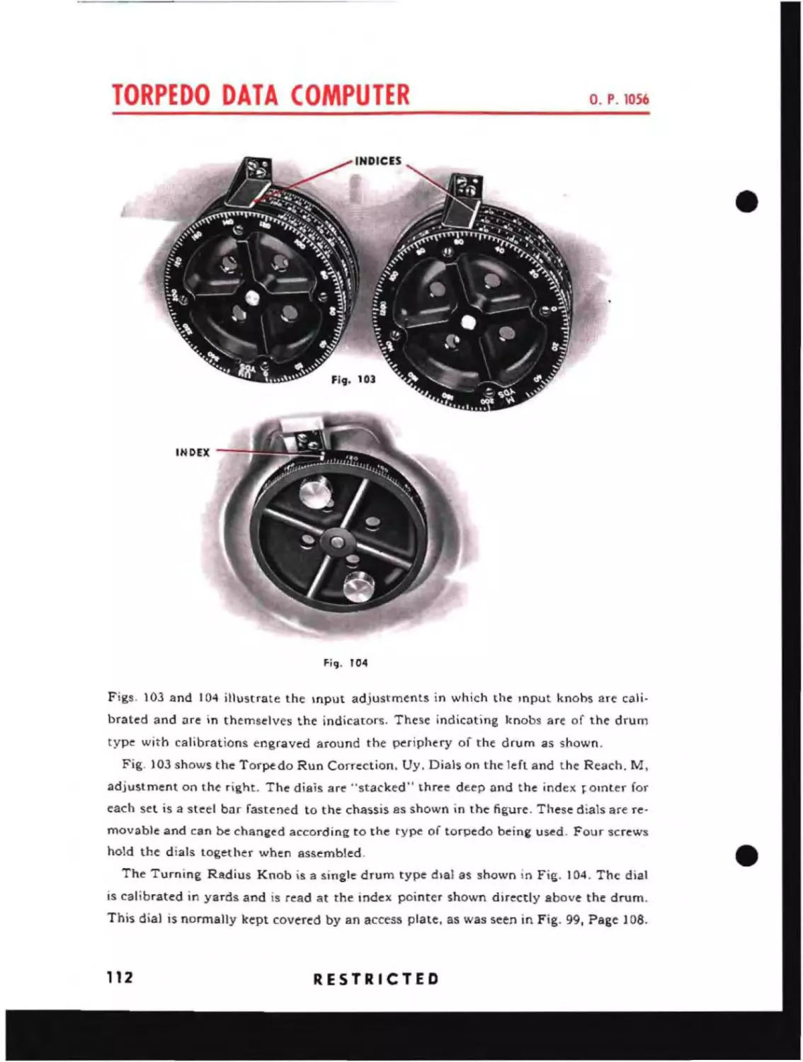
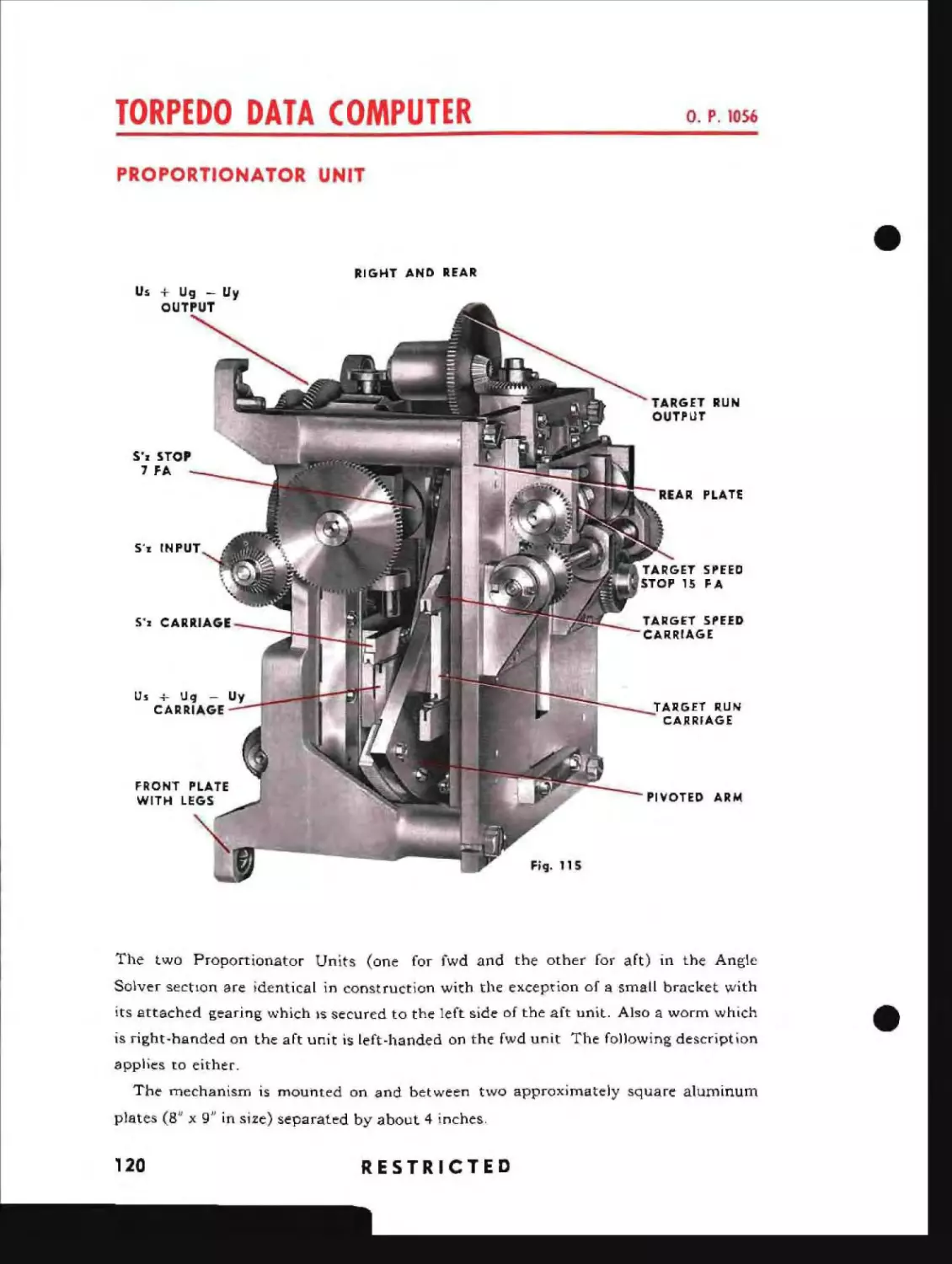
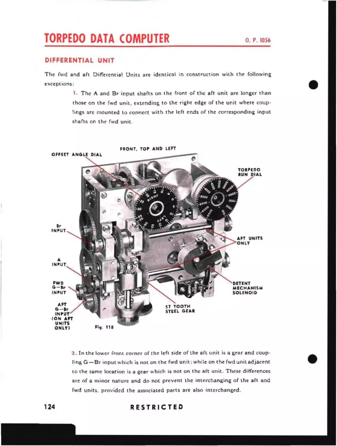
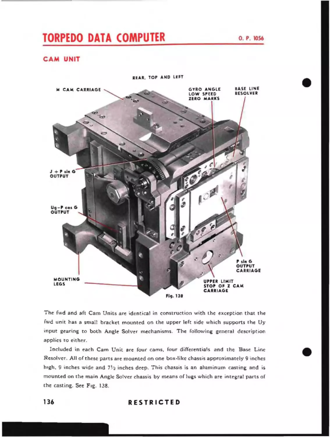
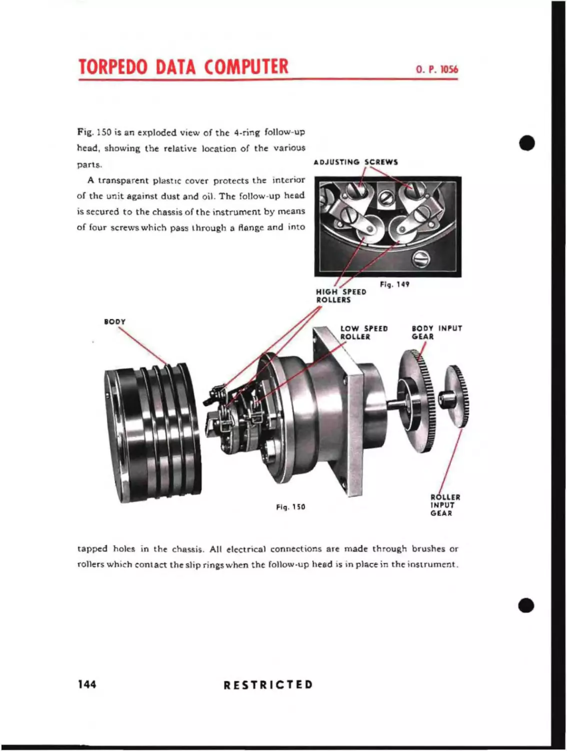
TORPEDO DATA COMPUTER
MARK 3, Mods. 5 to 12 Inclusive
JUNE, 1944
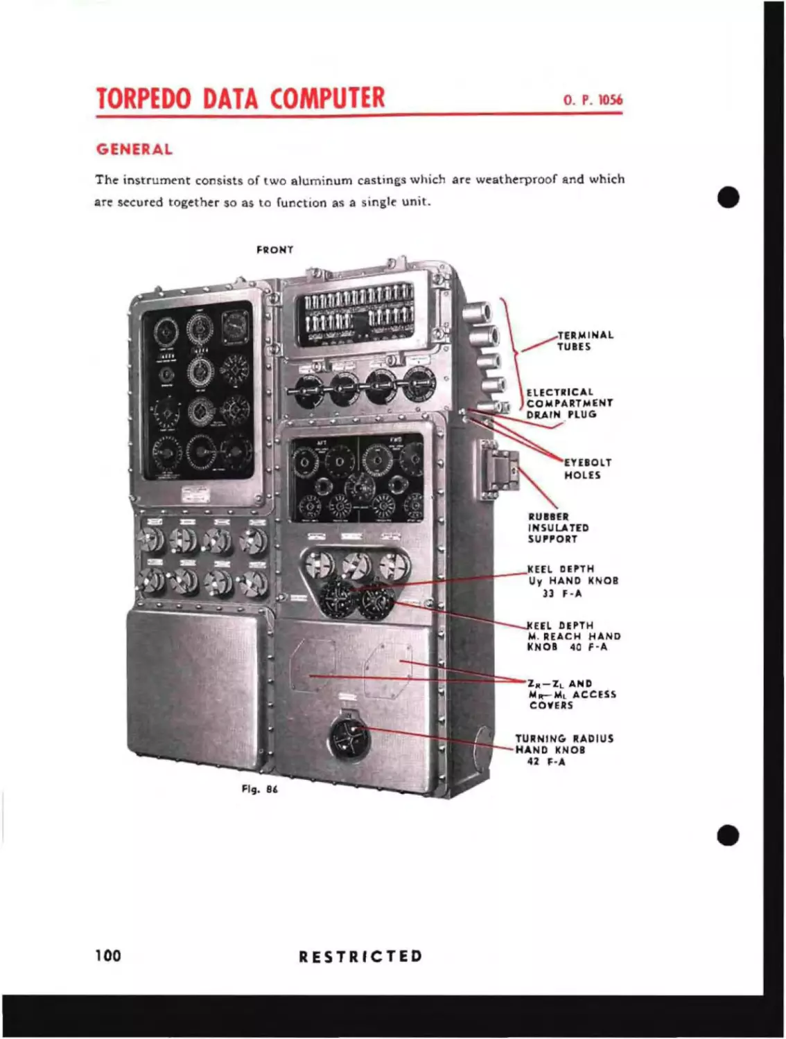
This Publication is RESTRICTED and will be handled in accordance with
Article 76, United States Naval Regulations, 1920
1
J
l~
Prep .. red for 'he Bur"au of Ordnan.e
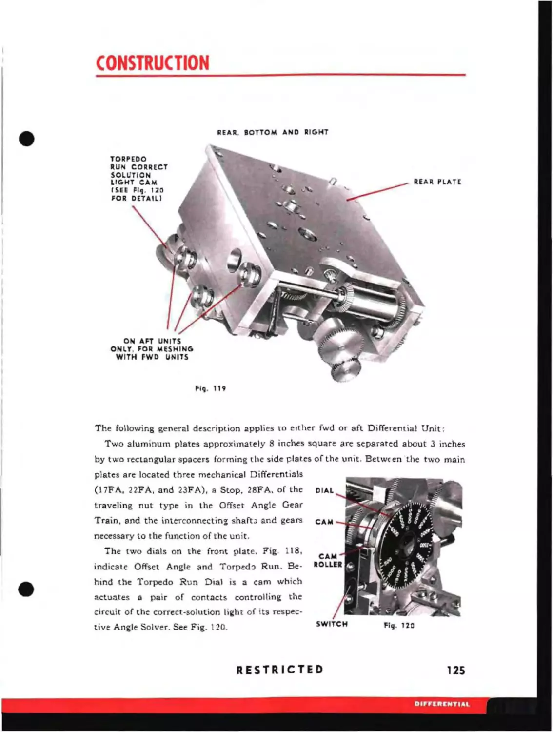
by the
ARMA CORPORATION
Brooklyn. New York
2
RESTRICTED
____
NAVY DEPARTMENT
BUREAU OF ORDNANCE
WASHINGTON, D. C.
•
JUNE, 1944
RESTRICTED
ORDNANCE PAMPHLET NO. 1051>TORPEDO DATA COMPUTER MARK 3 MODS. 5 TO 12.
1.
This Ordnance Pamphlet contains information on the descrip-
tion, operation, maintenance, and installation of the Torpedo Data Computer Mark 3
Mods. 5 to 12.
2.
The following publications pertain to the Torpedo Data Com-
puter Mark 3 Mods. 5 to l2 and accessories:
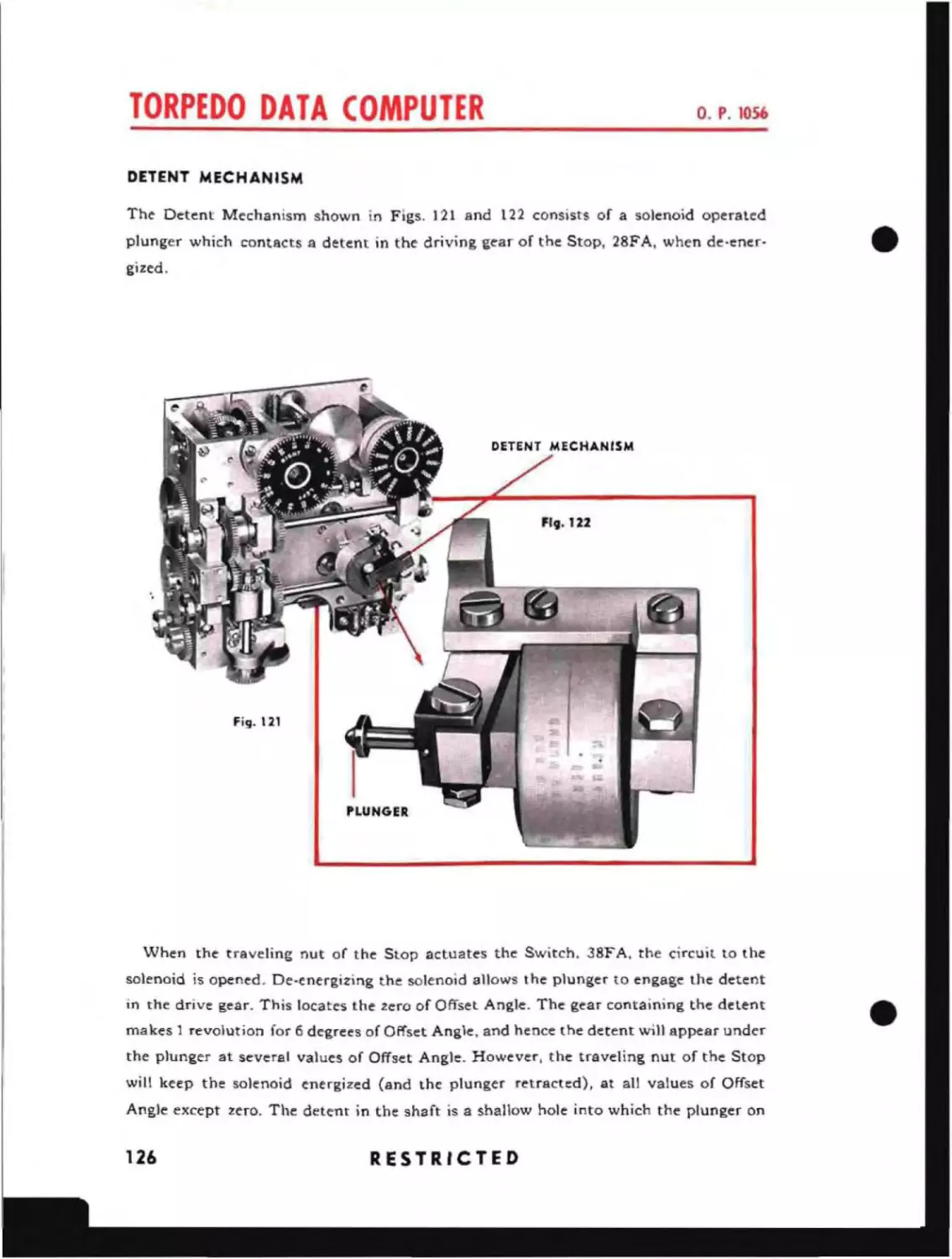
O.S. No. 2182
Specifications for Torpedo Control System for
Submarines
O.D. No. 2585
Gyro Setting Indicator ReguLator Mark 1 and
Mods. 1 and 2
0.0. No. 2561
Torpedo Data Computer Mark 3 Mods. 5 to 12,
inclusive
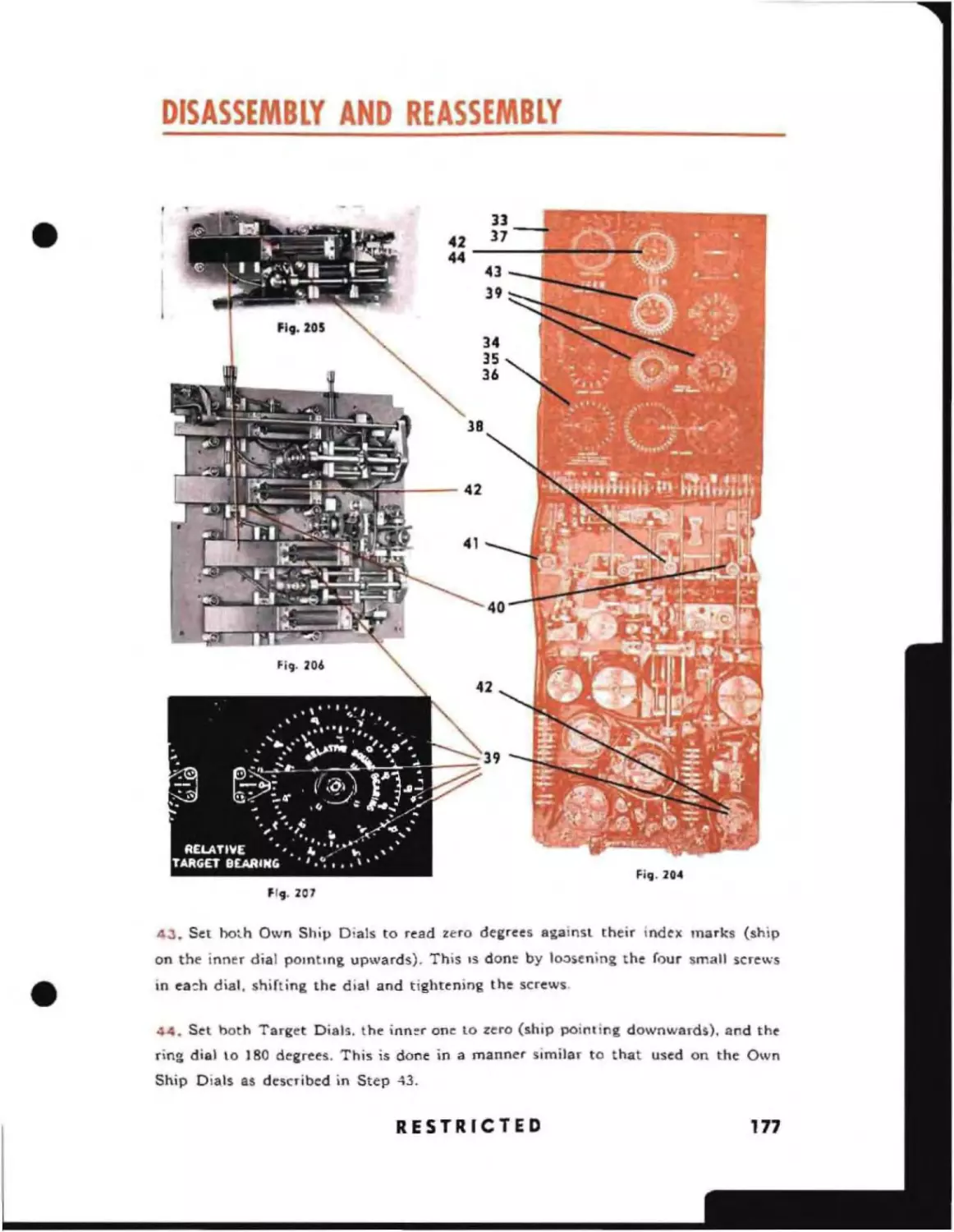
3.
Ordnance Data O.D. 2561 is now obsolete and should be
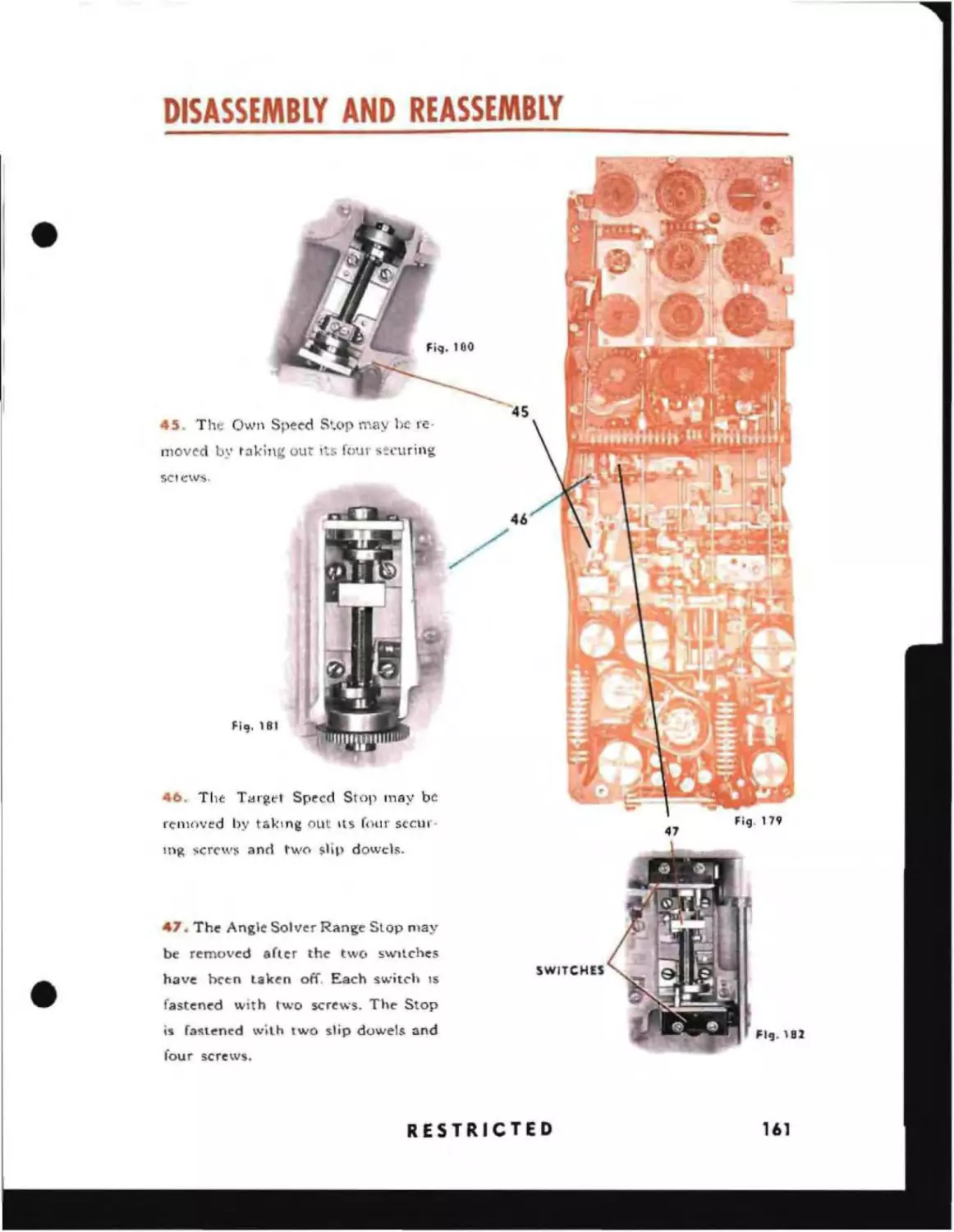
destroyed upon receipt of this publication.
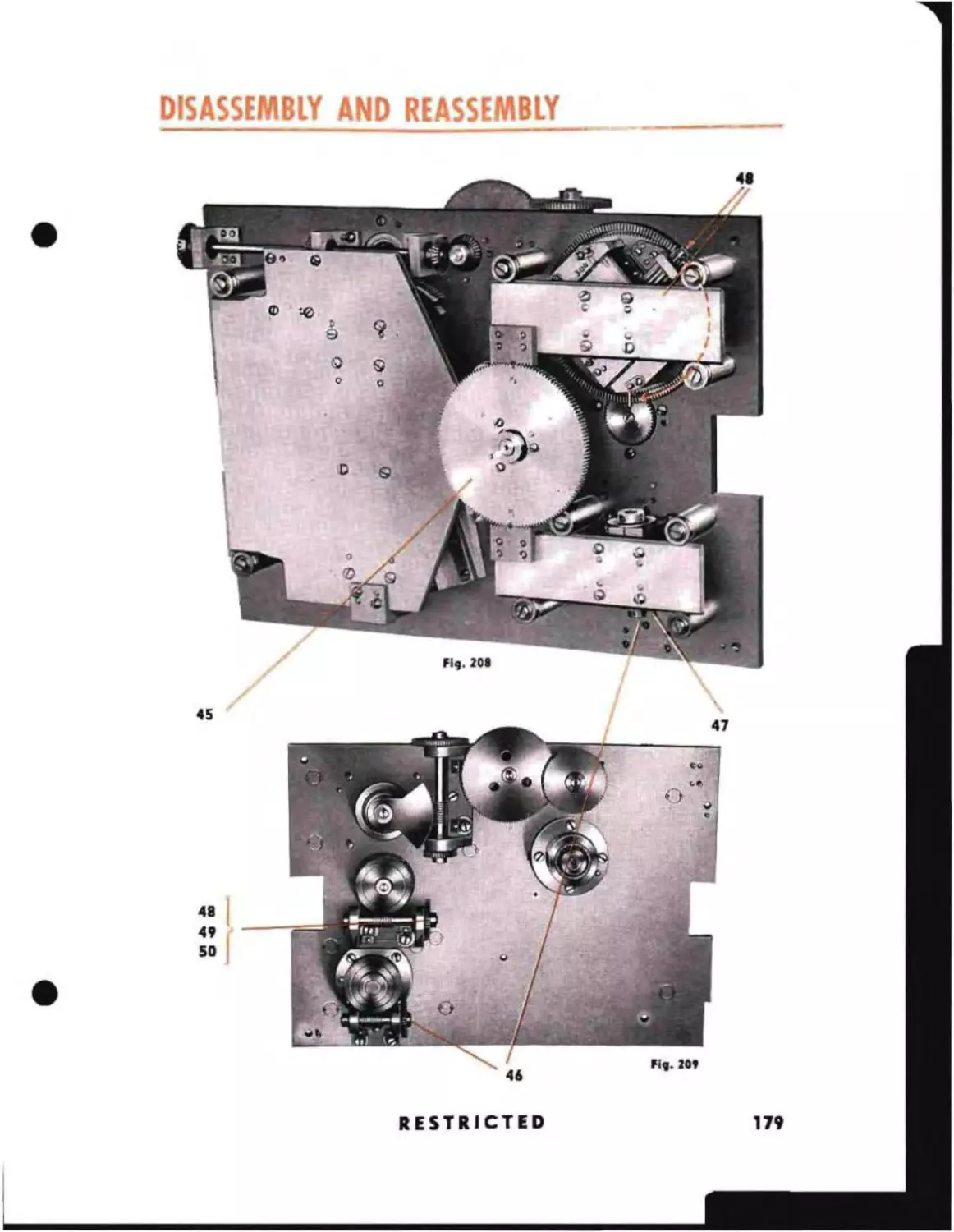
4.
Ordnance Pamphlet D.P. 1056 is classified as restricted and
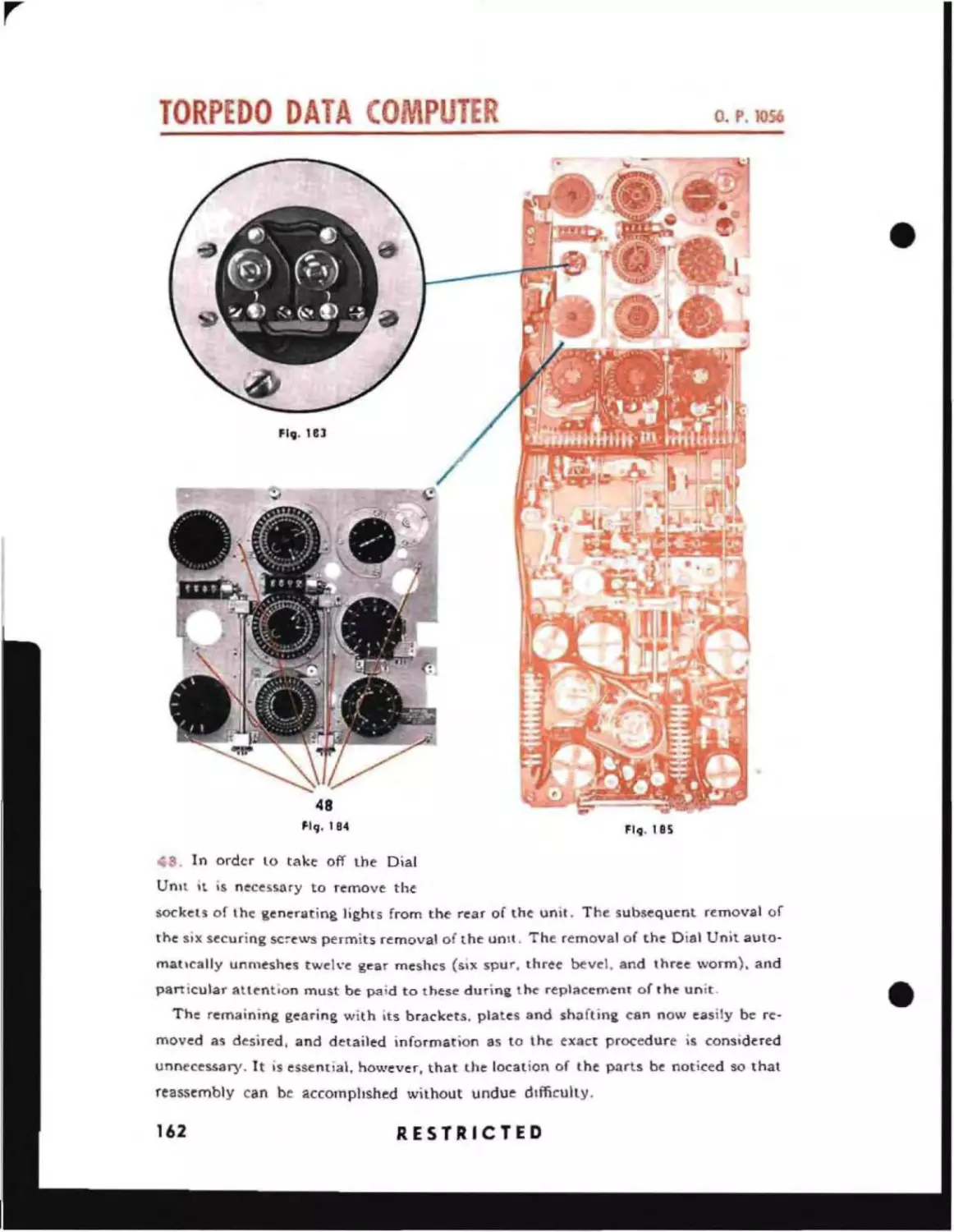
should be handled in accordance with the provisions of Article 76, Navy Regulations,
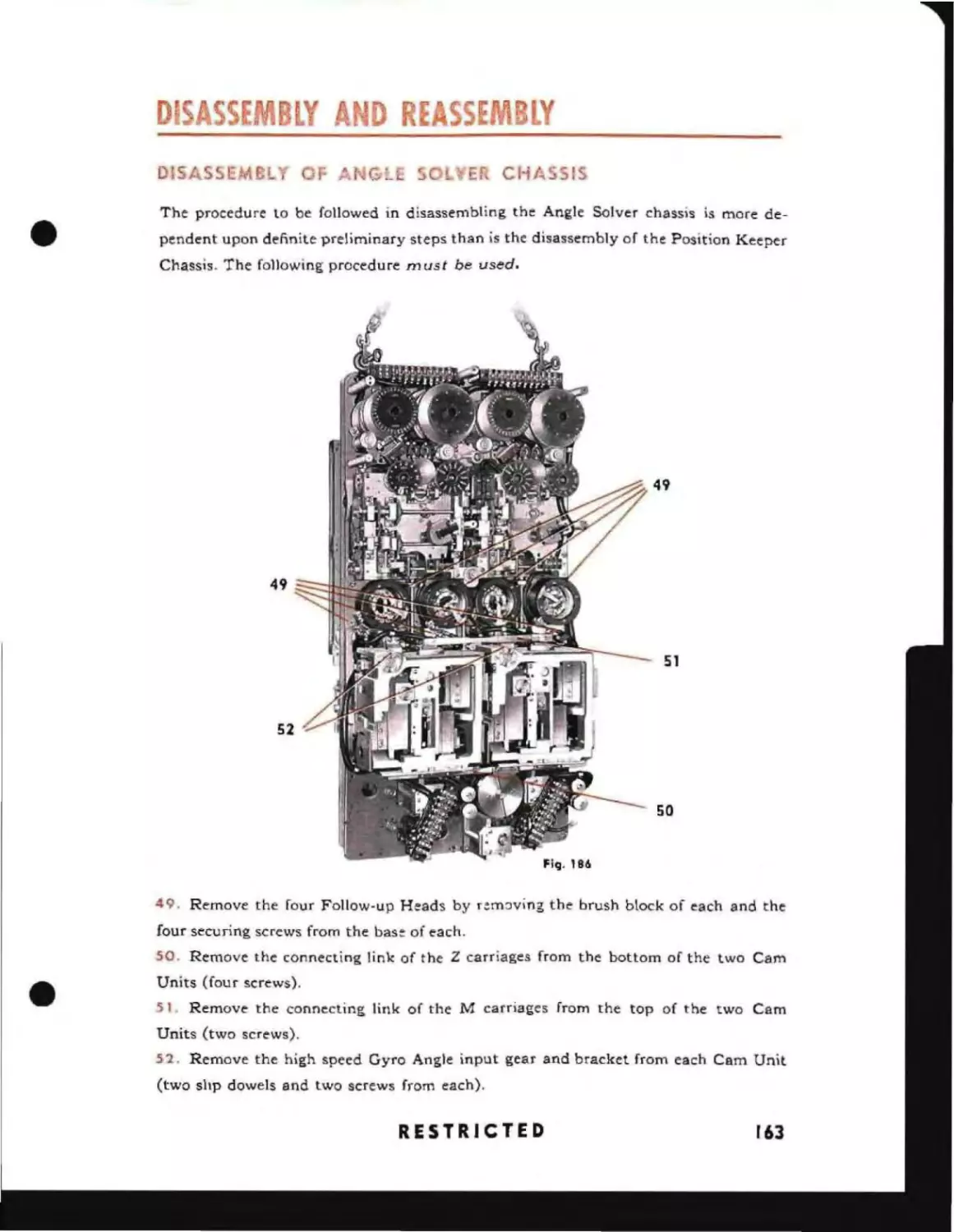
1920.
G. F. HUSSEY, ]R.
REAR ADMIRAL, U. S. NAVY
CHIEF OF BUREAU OF ORDNANCE
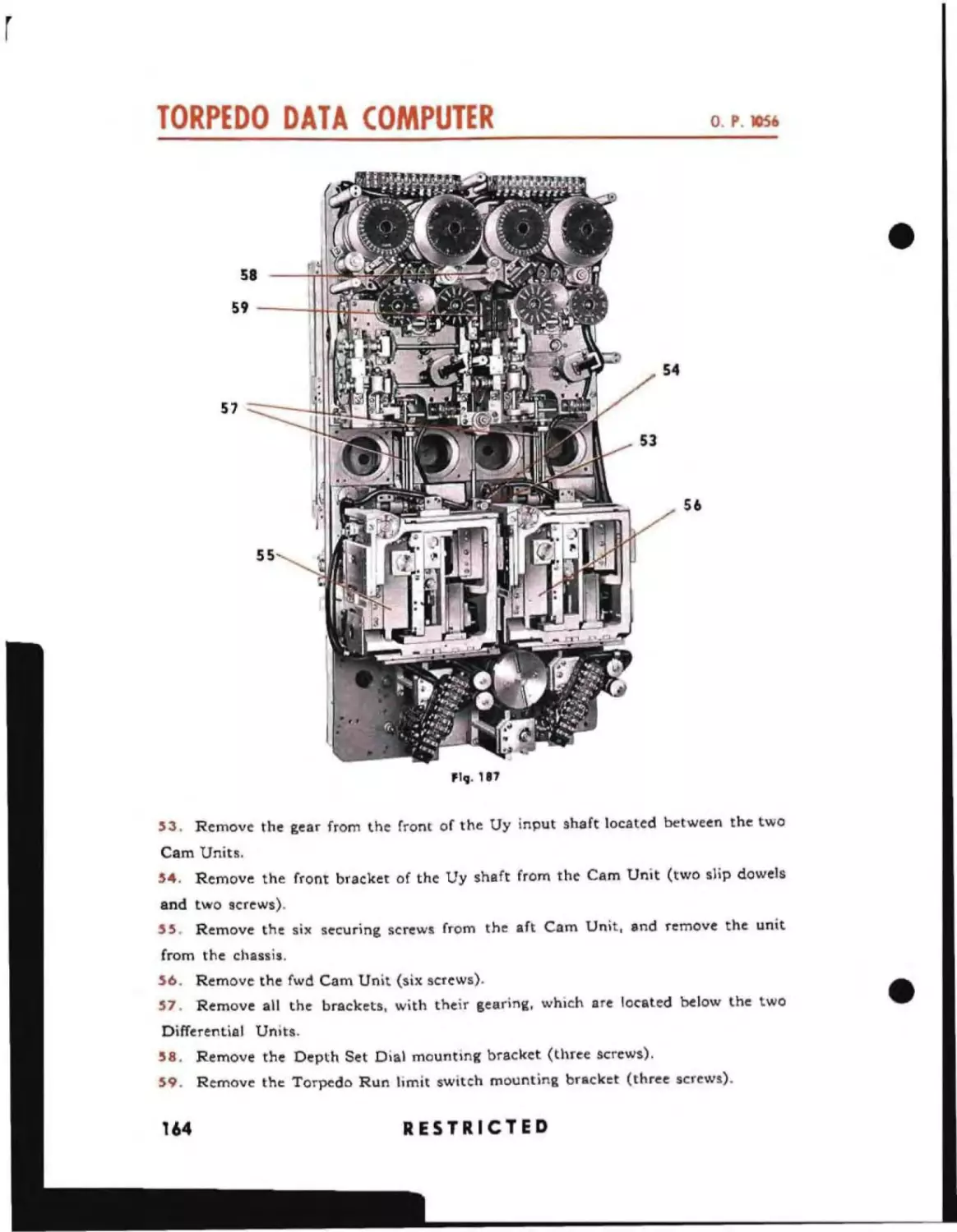
RESTRICTED
_ _ _......
3
,.4
TABLE OF CONTENTS
SECTION 1-"-"01)',,;\ of the Fin: Contrc>l P"-o+;'1
11
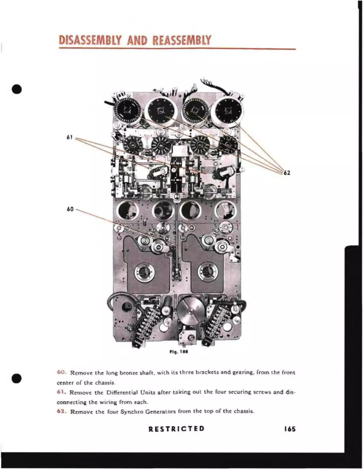
itf
Terminology and Symbols
13
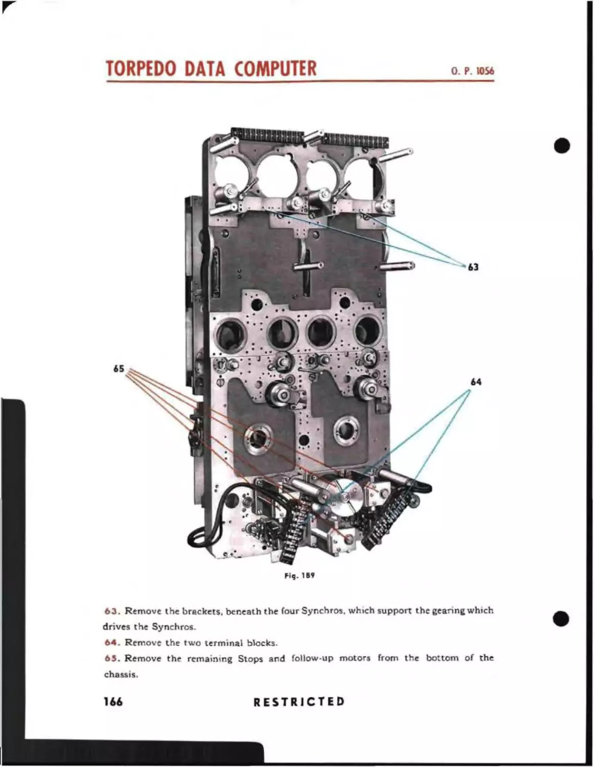
Distances
Speeds
Time
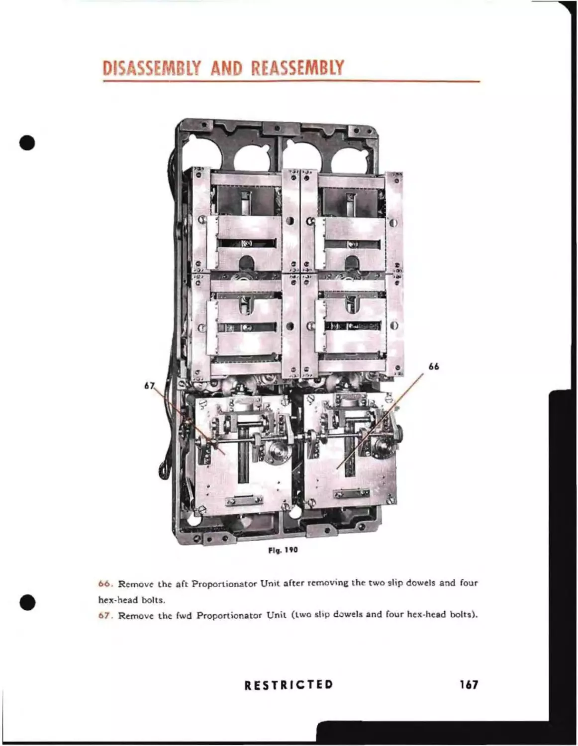
Angles
Review of Trigonometry
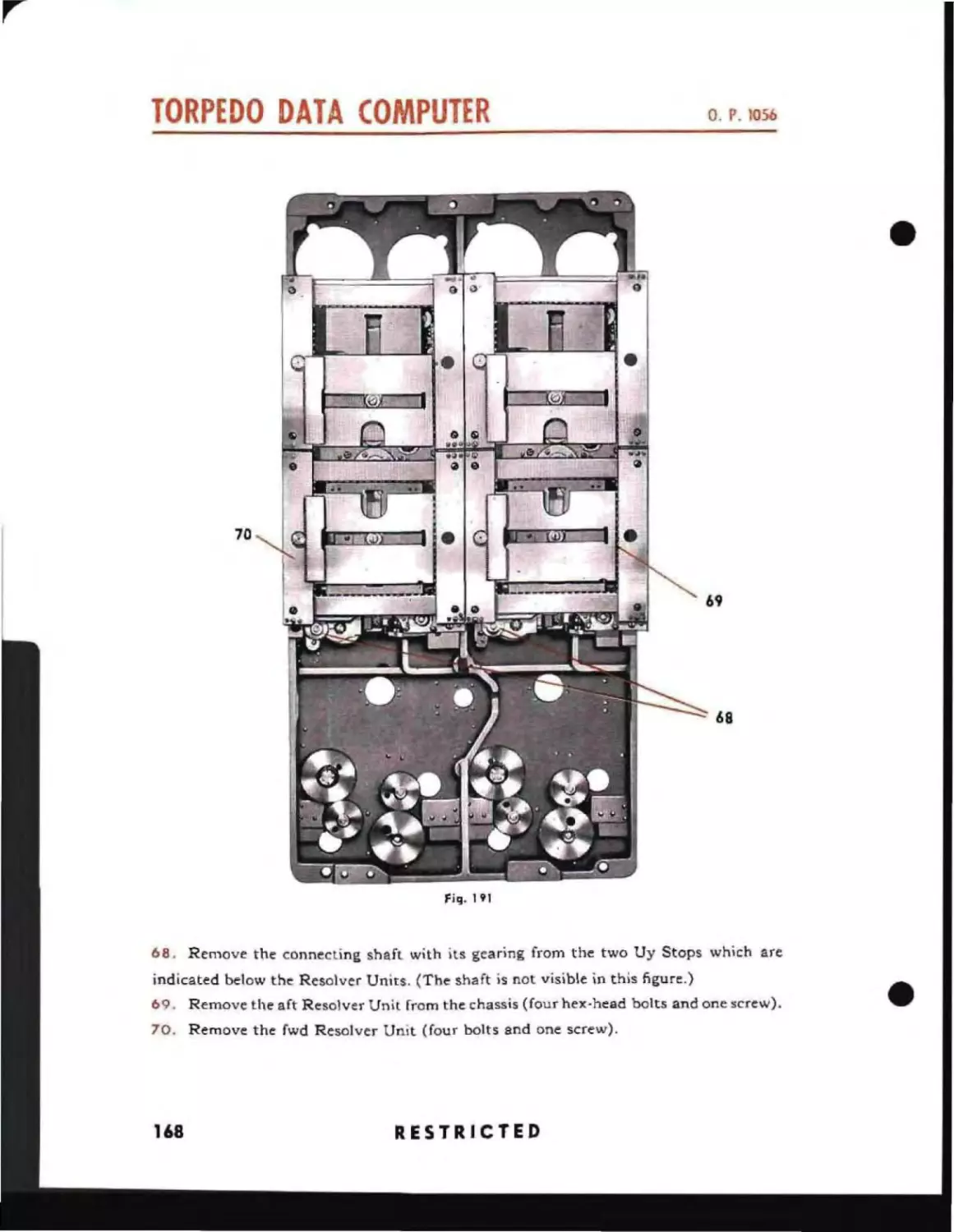
Derivation of Equations
General Problem
Derivation of Equations Solved by the Position Keeper
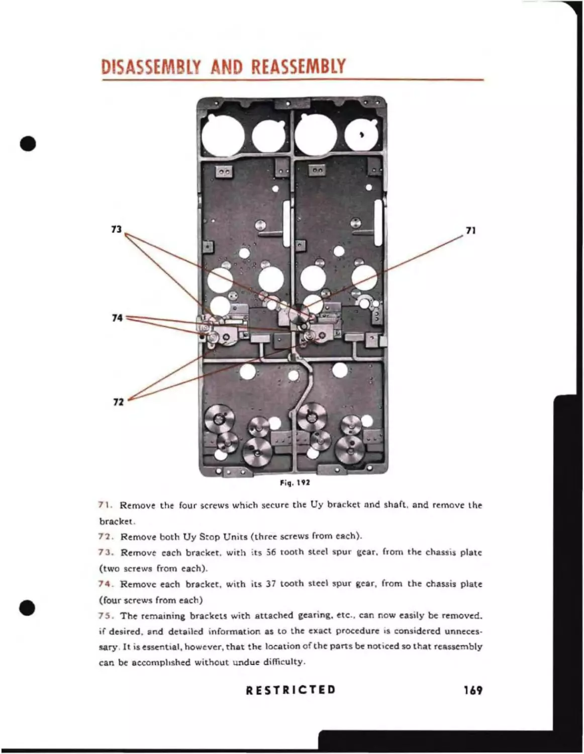
13
IS
15
15
18
21
21
22
Derivation of Equations Solved by the Sound Bearing
5fCTlON
Converter
Derivation of Equations Solved by the Angle Solver
27
29
~
33
34
F-u"!:l<:1melttaI5 of Cotnp-oncflh oct t:t"
DQt" Cot't\p~t ,
Differentials
Integrator
42
44
48
50
Resolvers
Proponi onator
Follow-up Head
General Function of the Computer
52
54
5S
56
Mechanical Follow-up Heads
58
Integrator Unit
Divider Unit
66
67
Position Keeper
68
Cams
Dials
Functional Diagram of Position Keeper and Sound Bearing
Converter
Functional Description of Position Keeper
68A
69
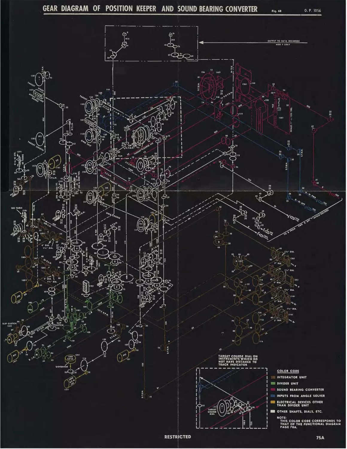
Gear DIagram of Position Keeper and Sound Bearing
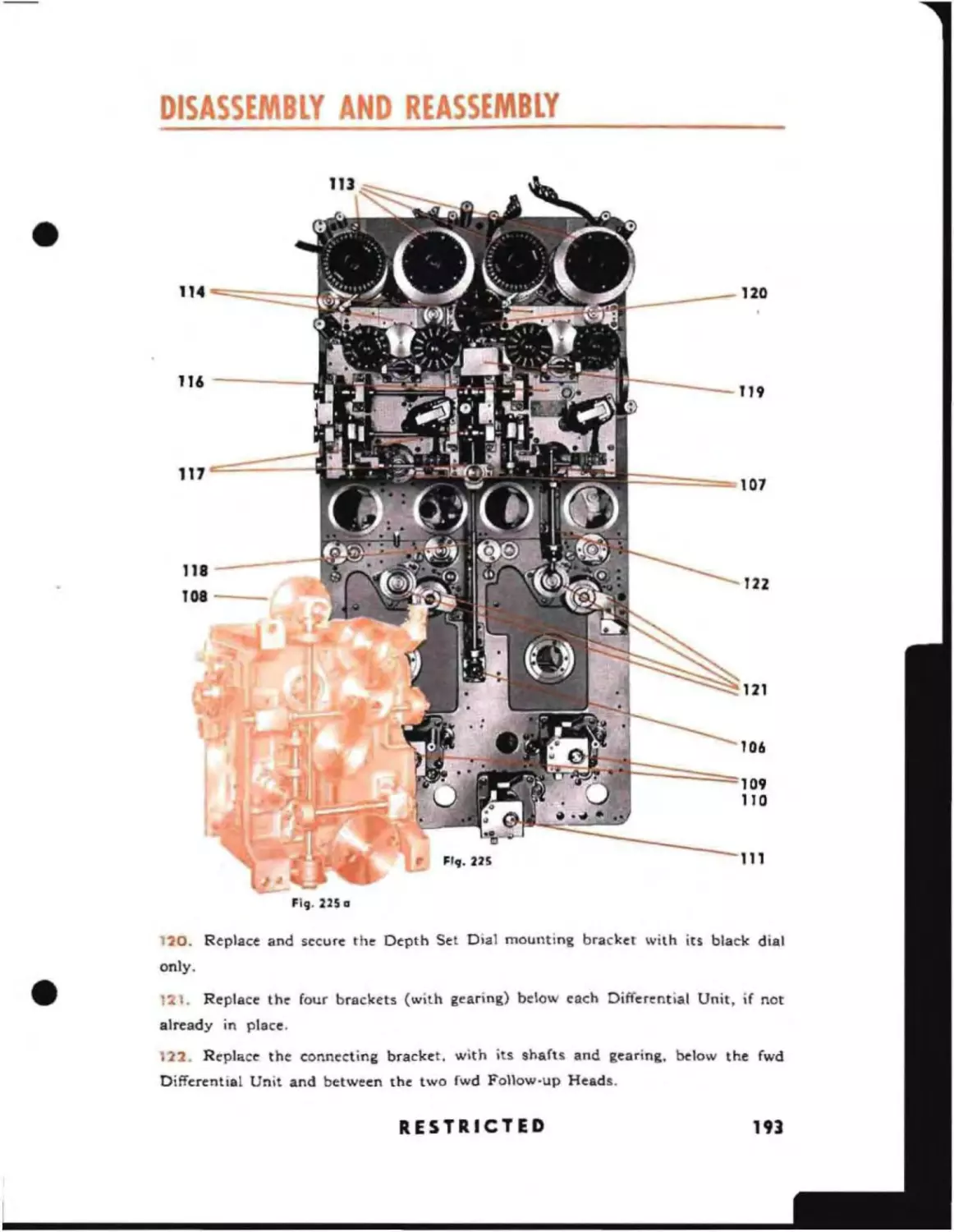
Converter
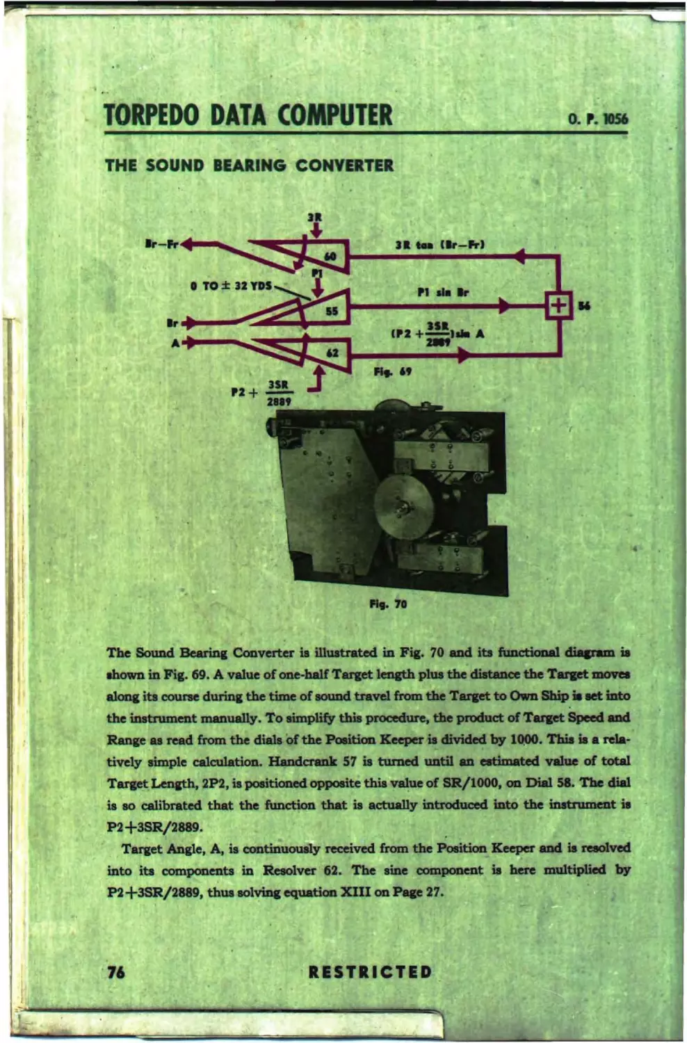
The Sound Bearing Converter
75A
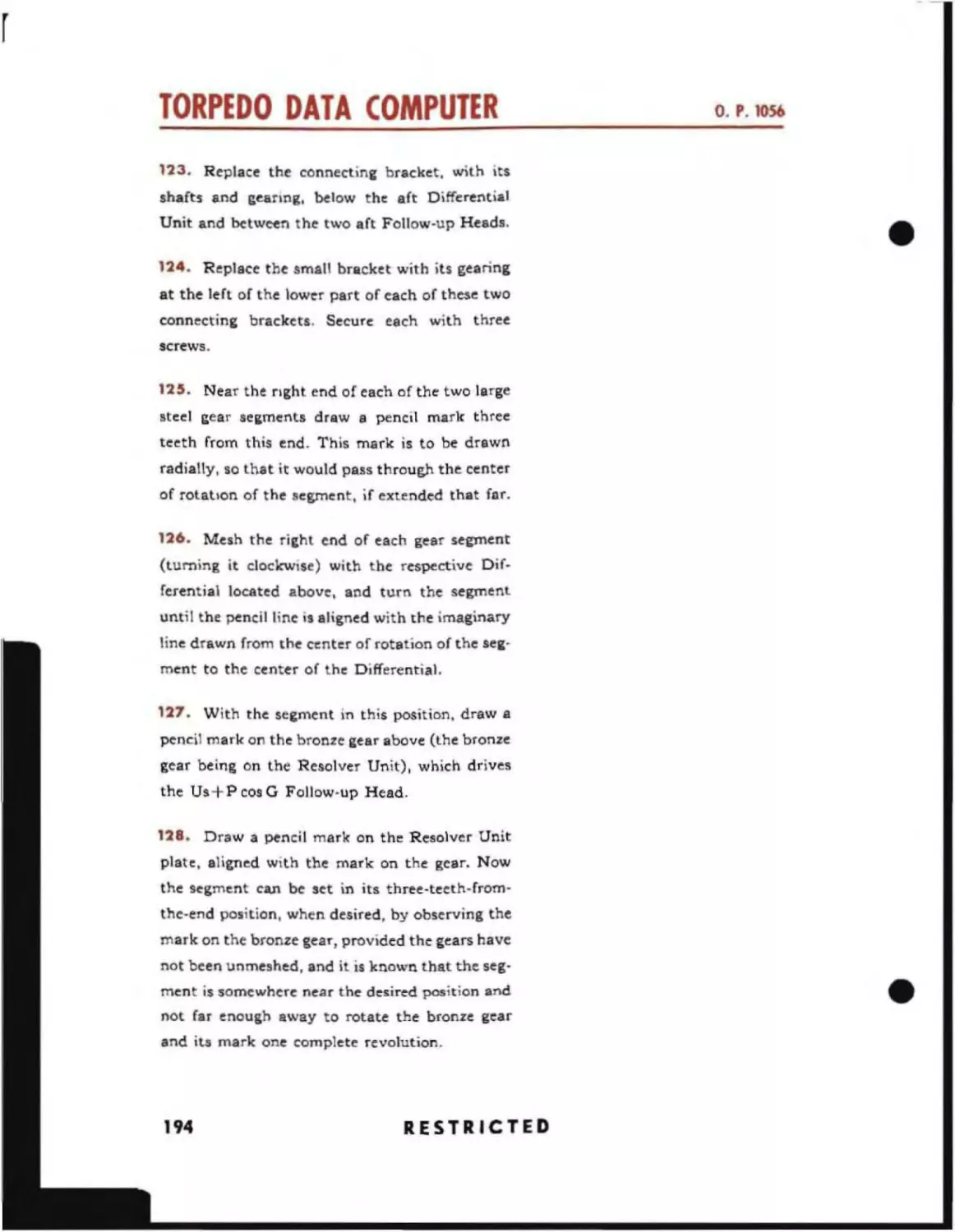
76
Unit Assembly Diagram of Position Keeper and Sound
78A
79
80
Bearing Converter
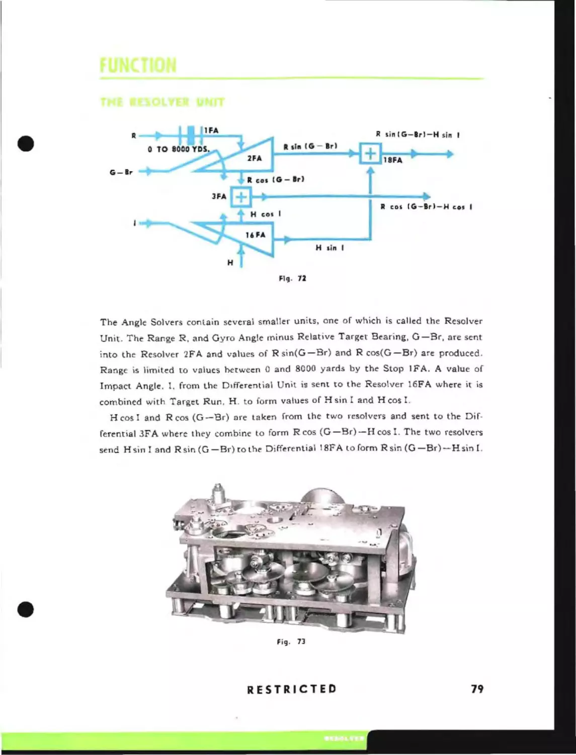
Resolver Unit
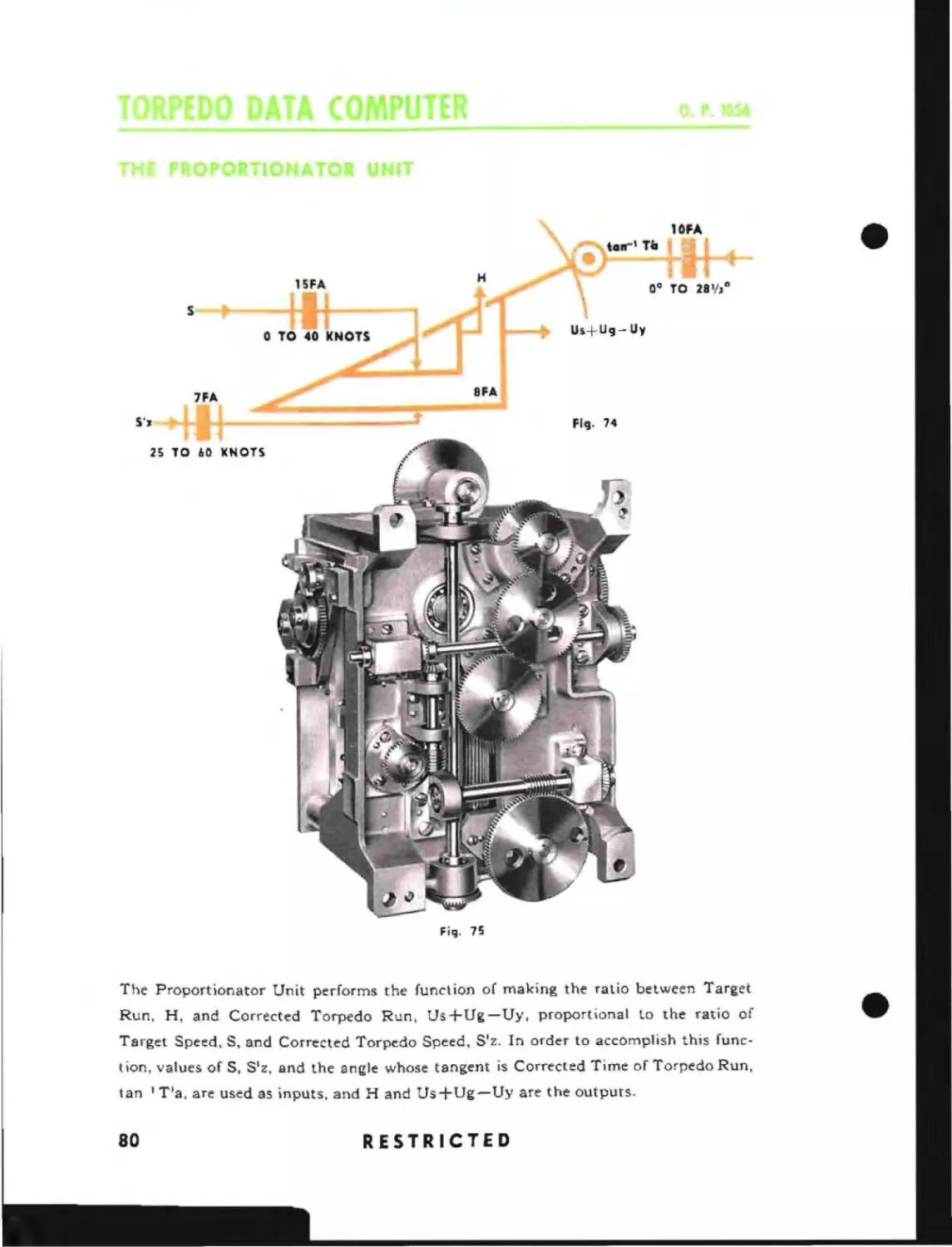
Proportionator Unit
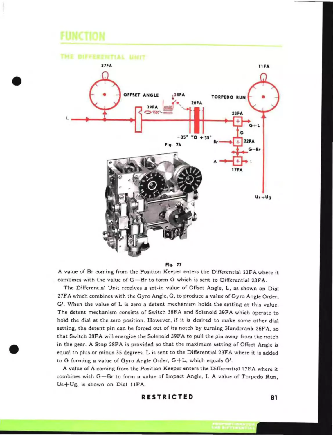
Differential Unit
81
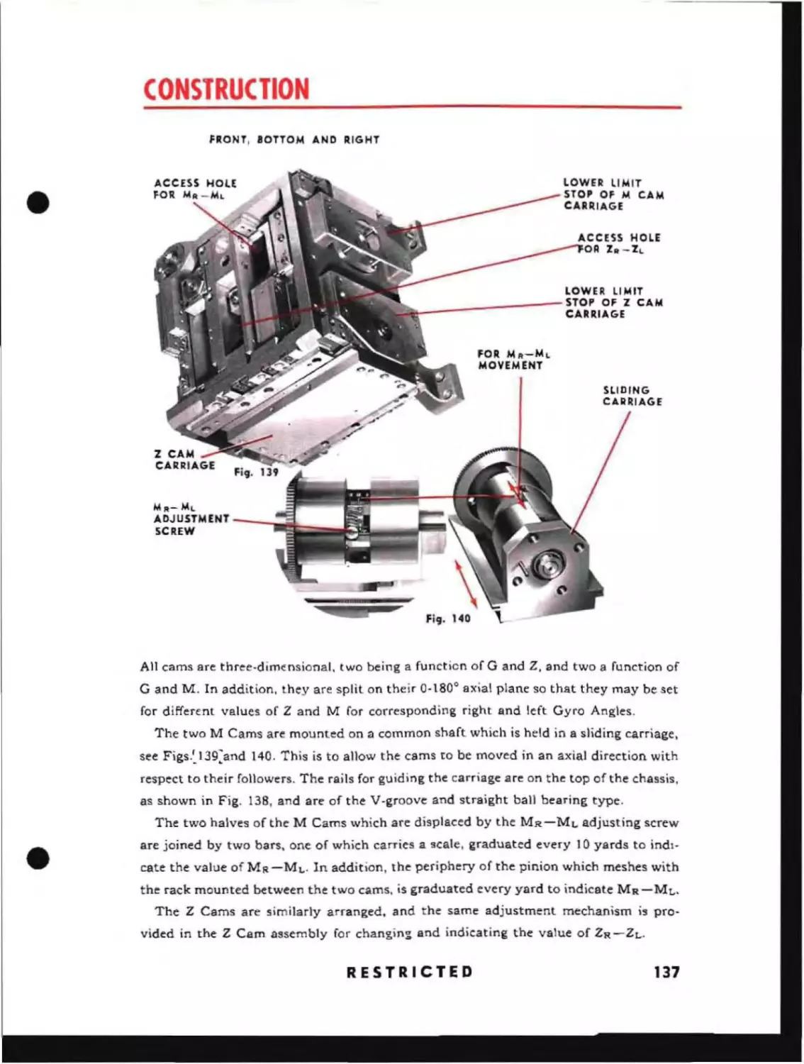
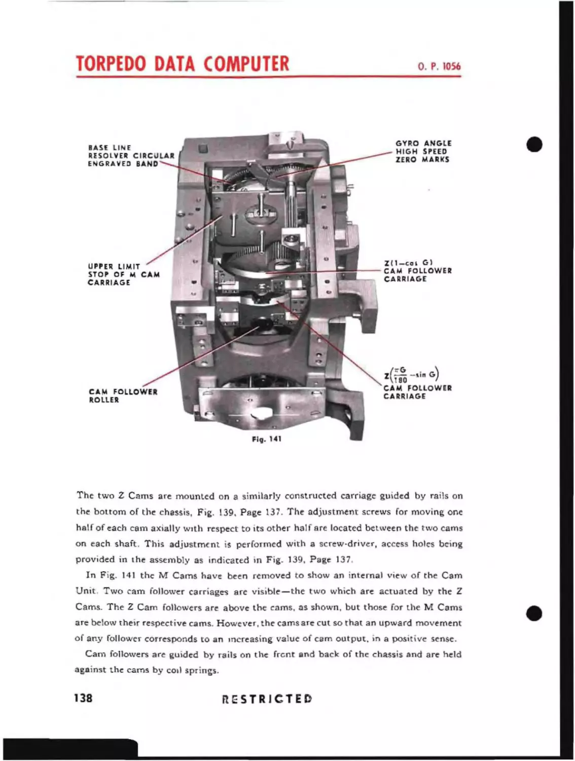
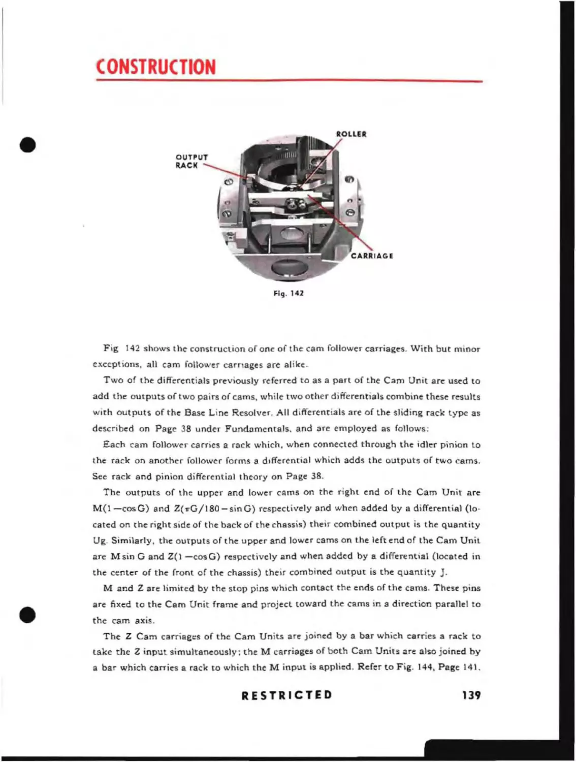
Cam Unit
82
84
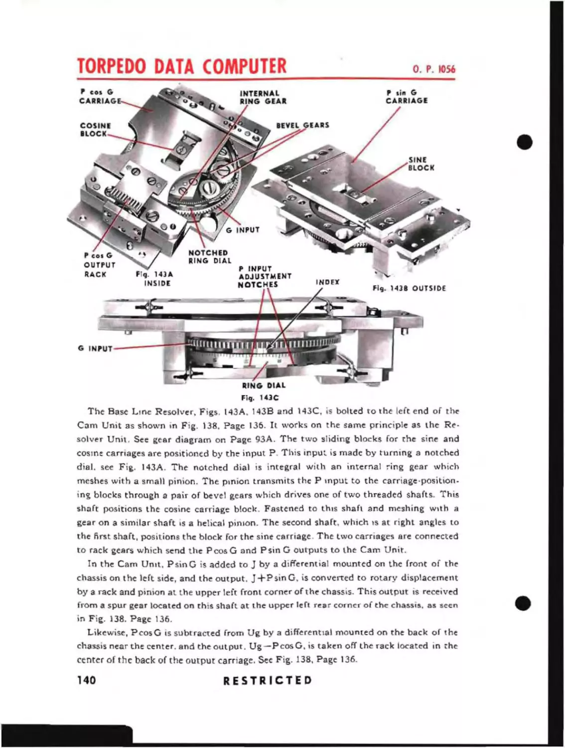
Base Line Resolver
RESTRICTED
~
5
J.
l
Angle Solvers
Functional Diagram of the fwd Angle Solver
Functional'Description of the Angle Solver
Gear Diagram of the fwd Angle Solver
93A
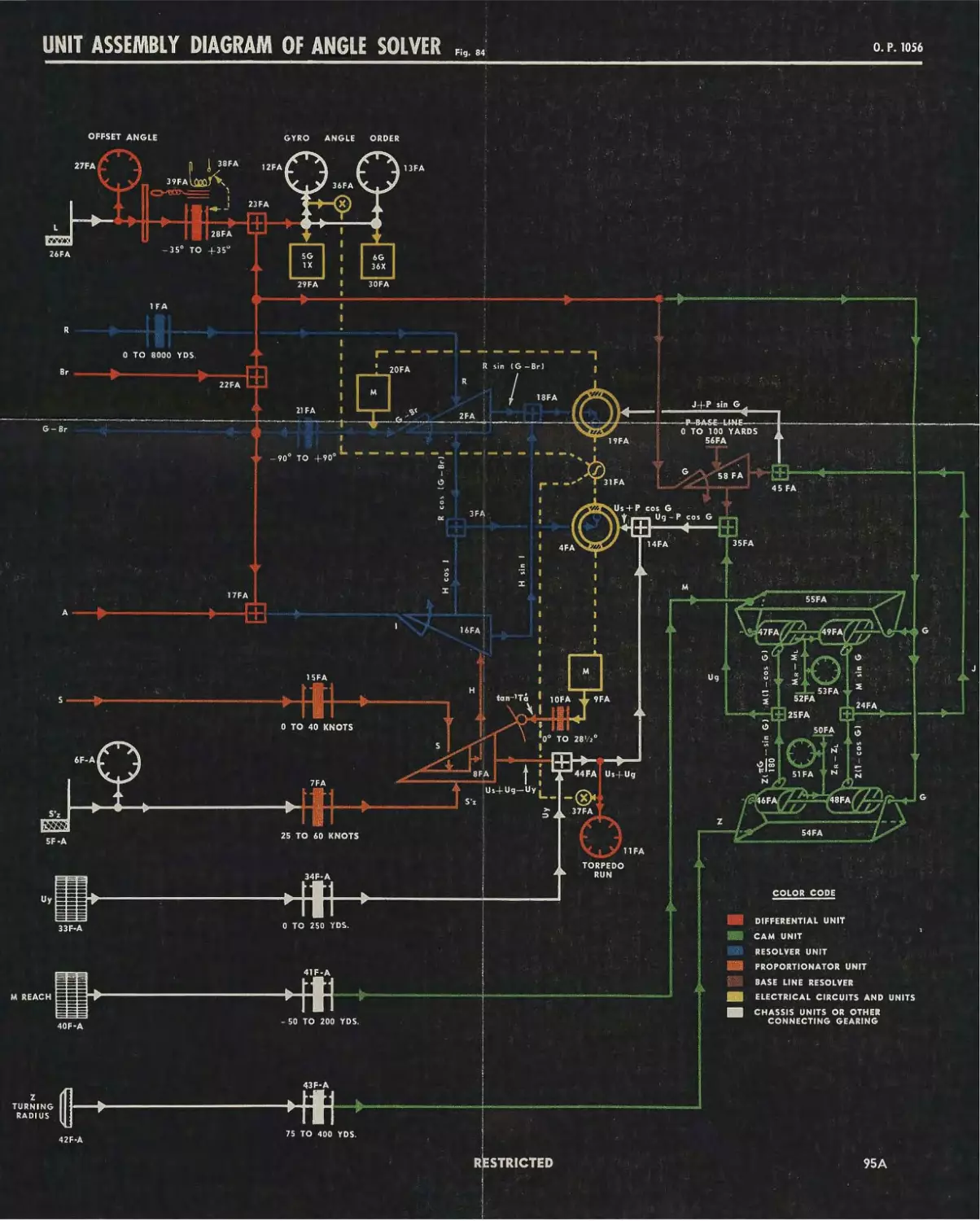
Unit Assembly Diagram of the fwd Angle Solver
95A
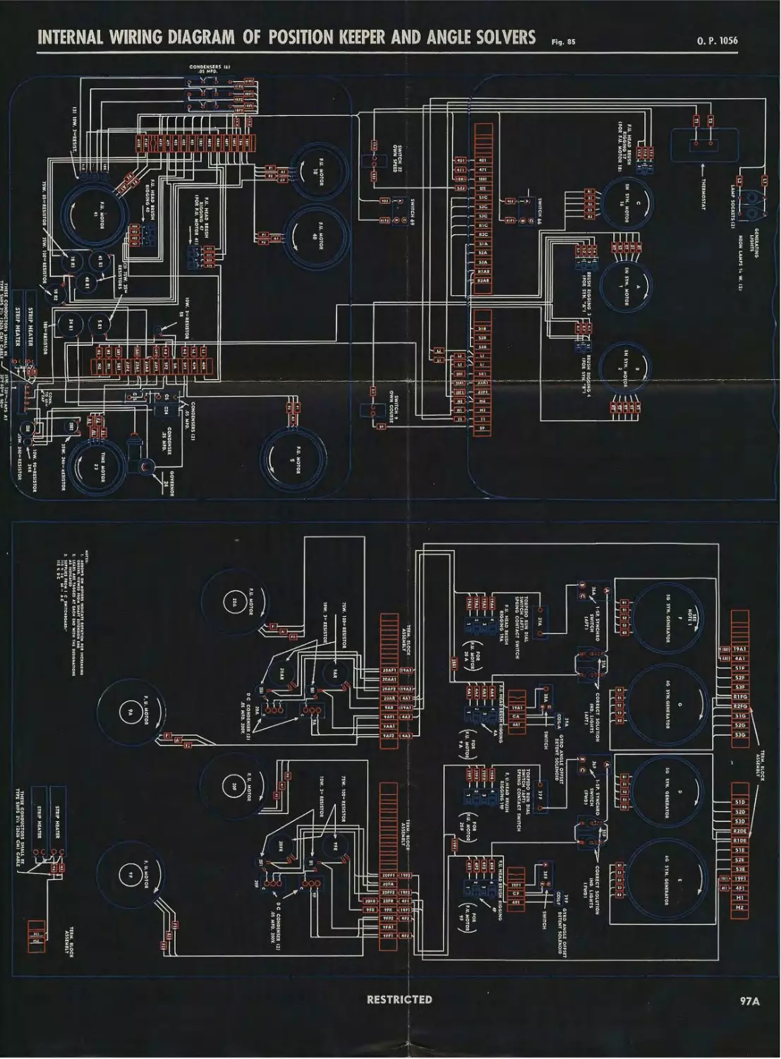
Inlernal Wiring Diagram of Angle Solver and Position Keeper
SECTION 4
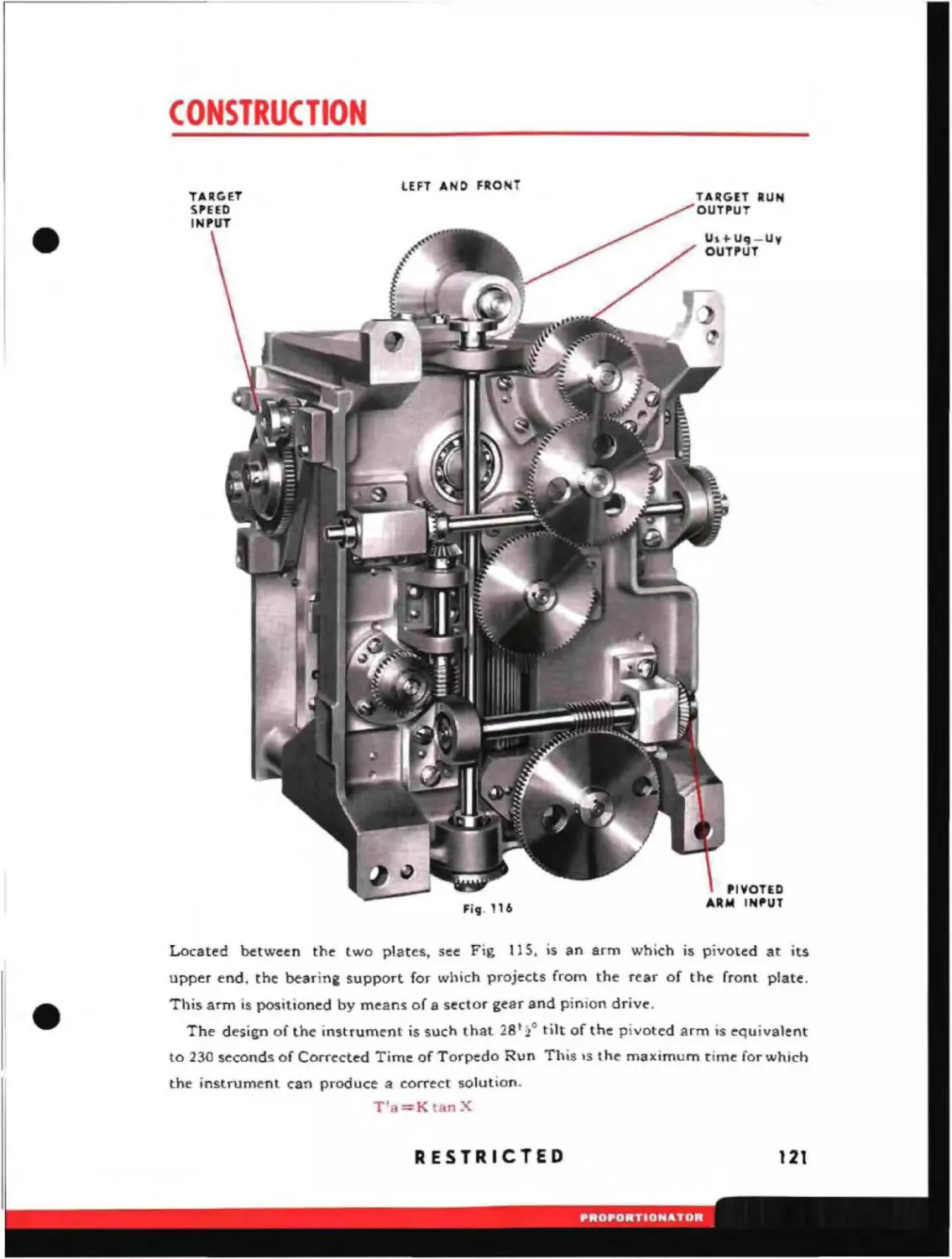
Co"~tfl\ct.on
99
General
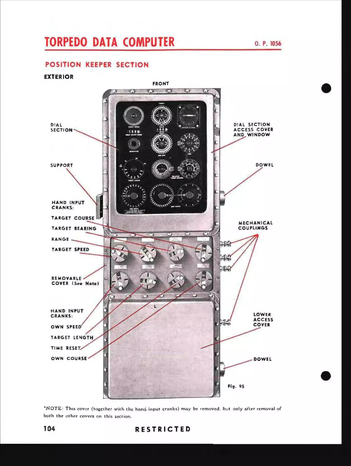
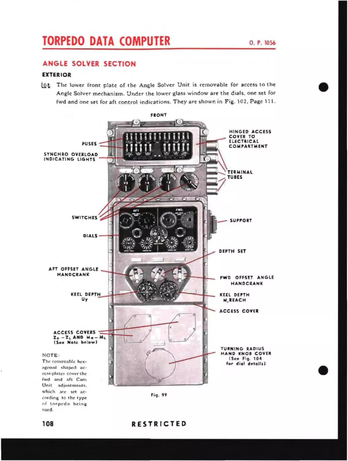
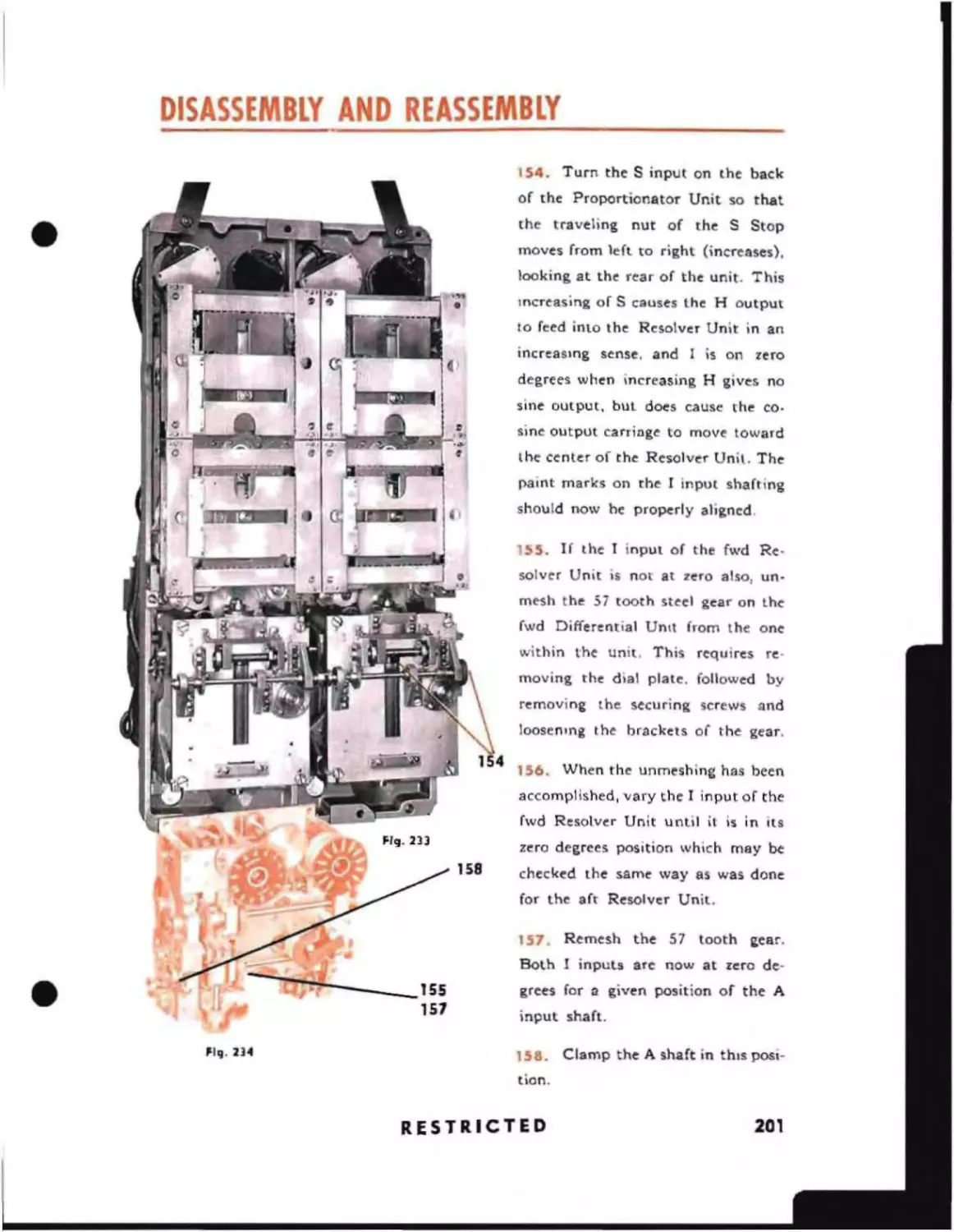
Extenor
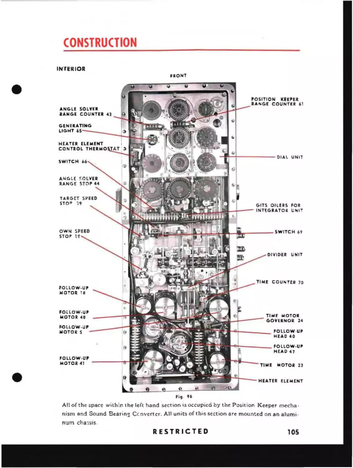
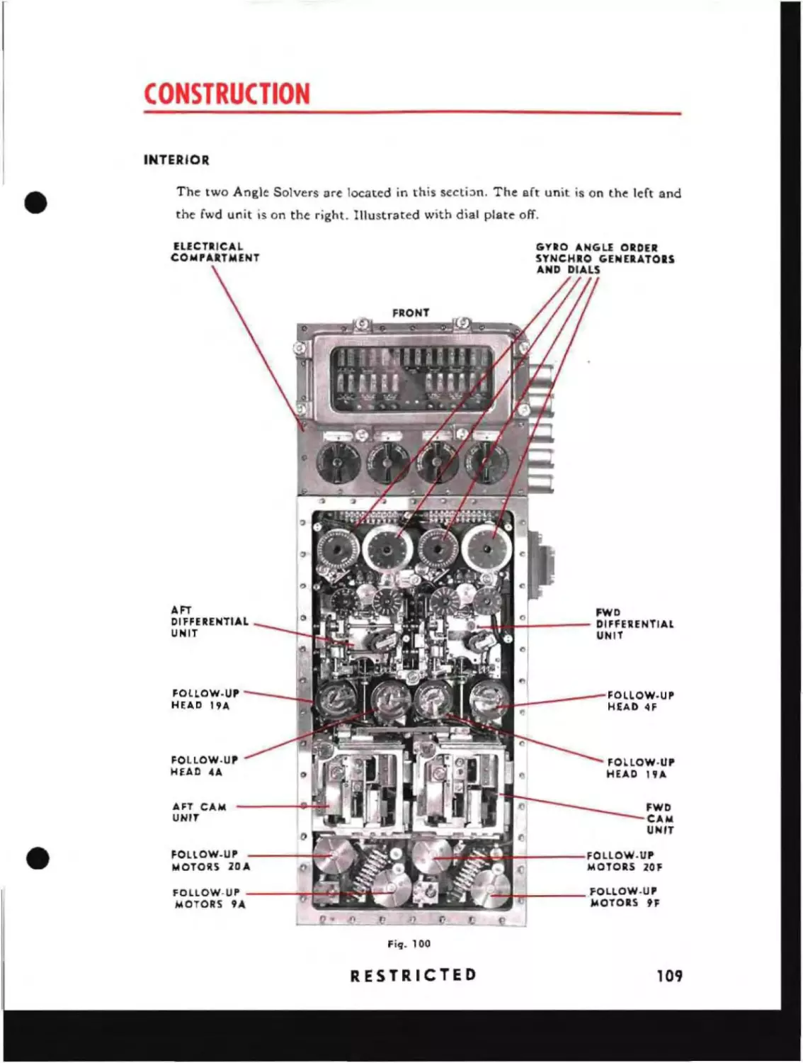
Interior
IDS
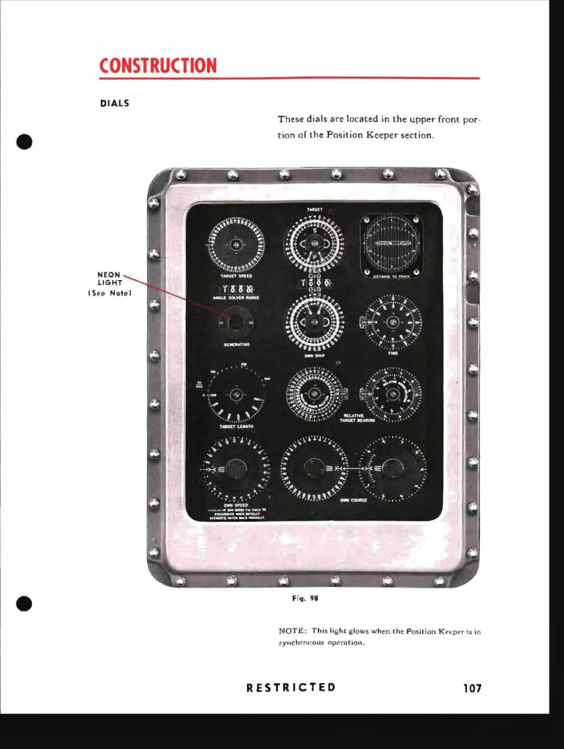
Dials
107
108
Angle Solver Section
Interior
108
109
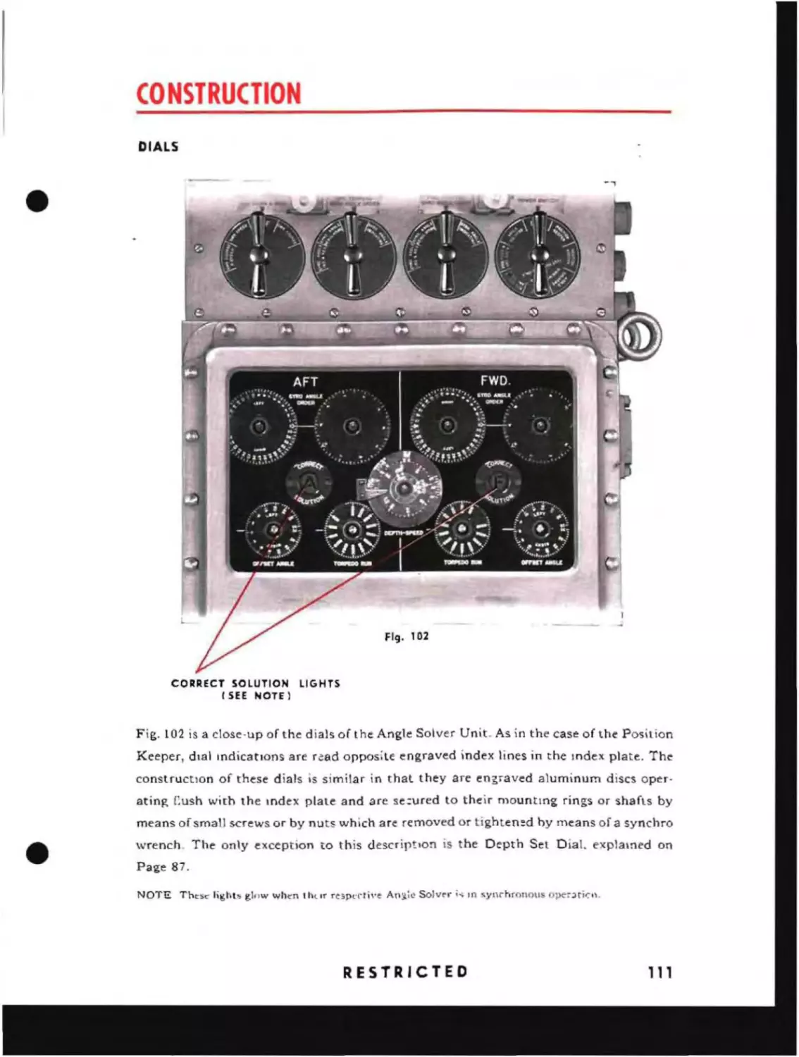
Dials
111
Exterior
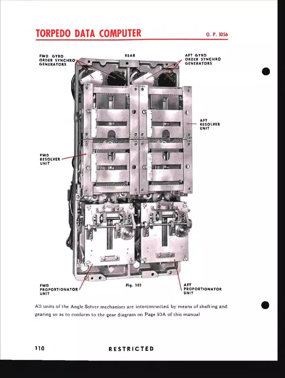
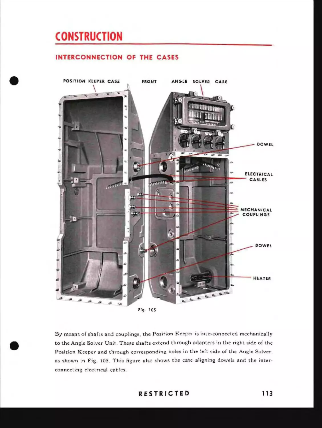
Interconnection of the Cases
113
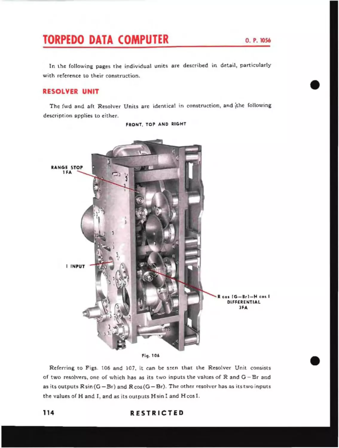
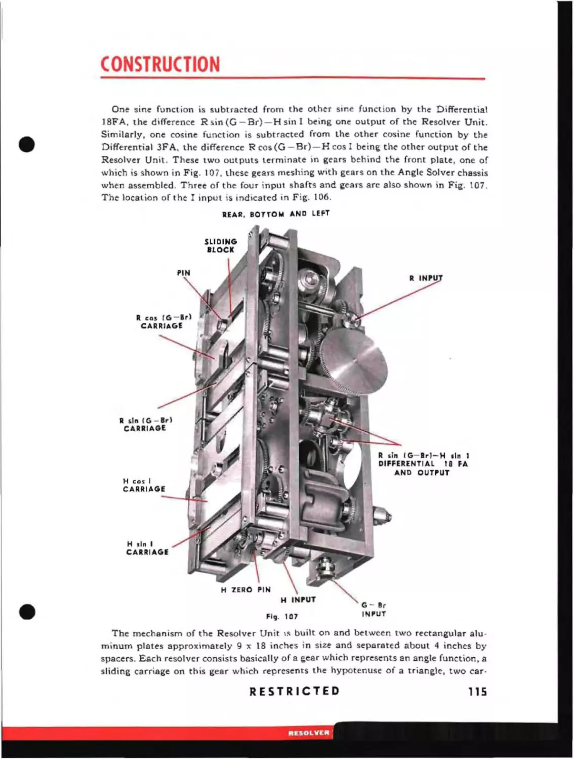
Resolver Unit
114
Proportionator Unit
Time Motor Governor
120
124
126
127
128
Integrator Unit
129
Sound Bearing Converter
Cam Unit
Stops
132
136
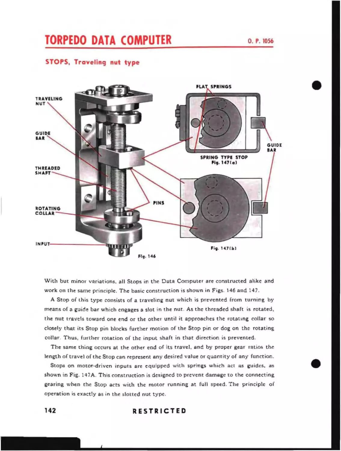
142
Follow-up Heads
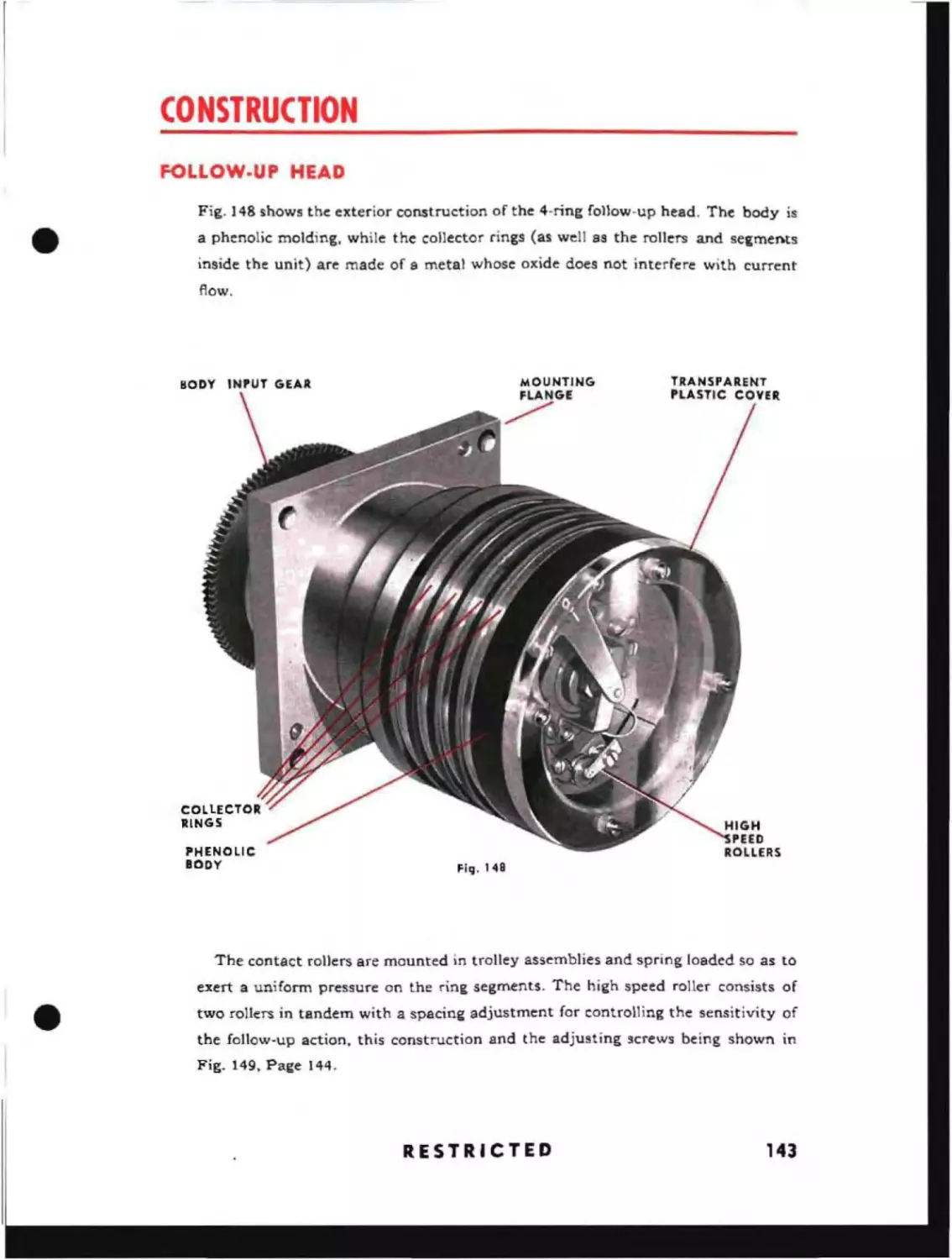
143
Differential Unit
Detent Mechanism
Divider Unit .
~ECTIC~'
5
D·'.{l~'c."l-ly
c~,:
RC'OSH;'
b,y
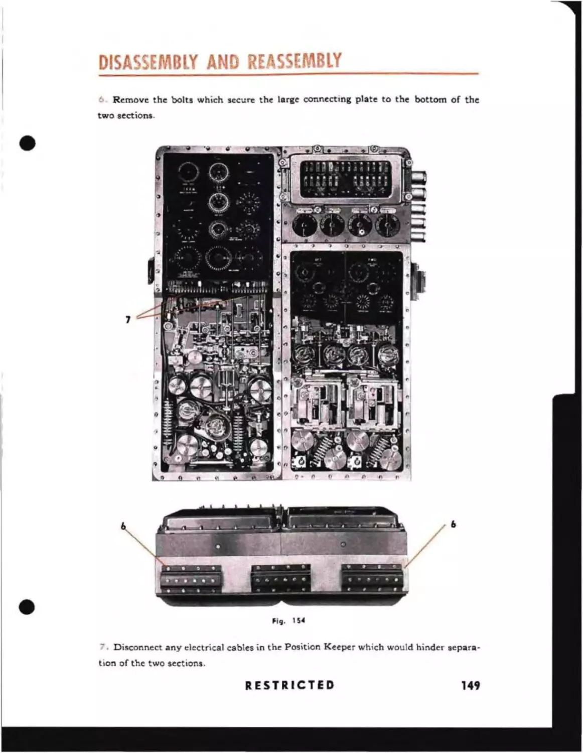
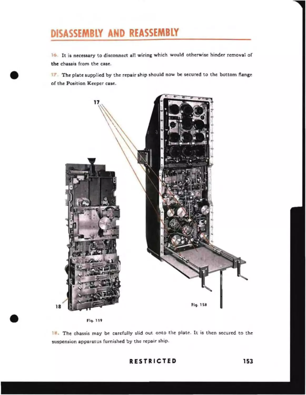
Separation and Removal of Chassis .
145
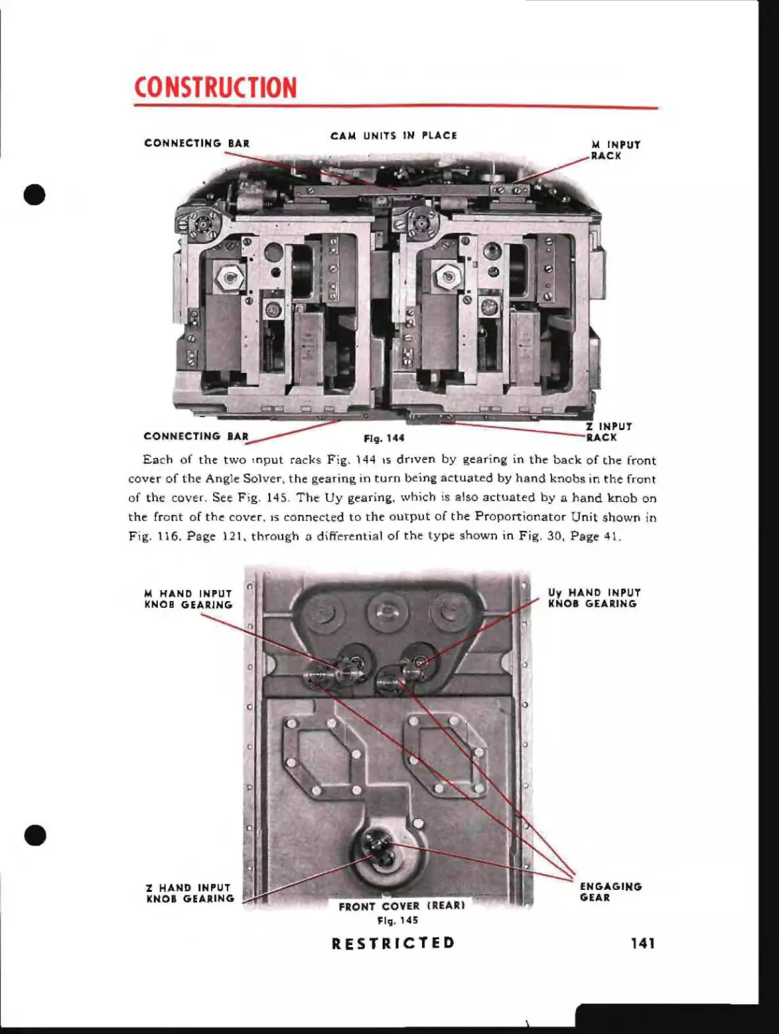
146
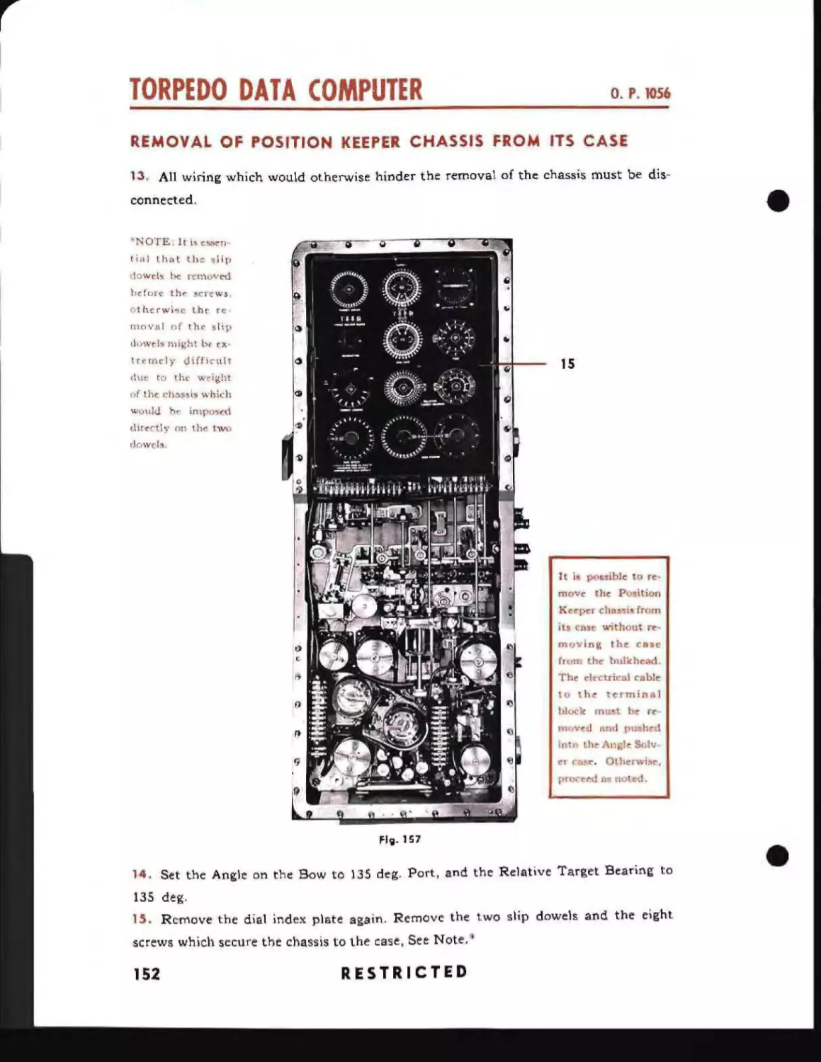
Removal of Position Keeper From Case
152
Removal of Angle Solver From Case
154
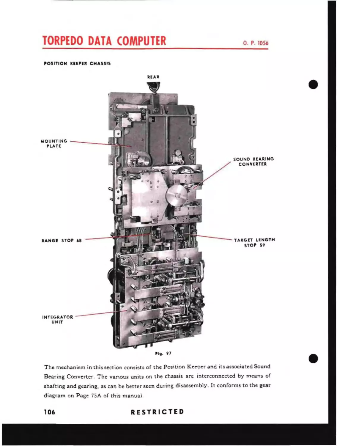
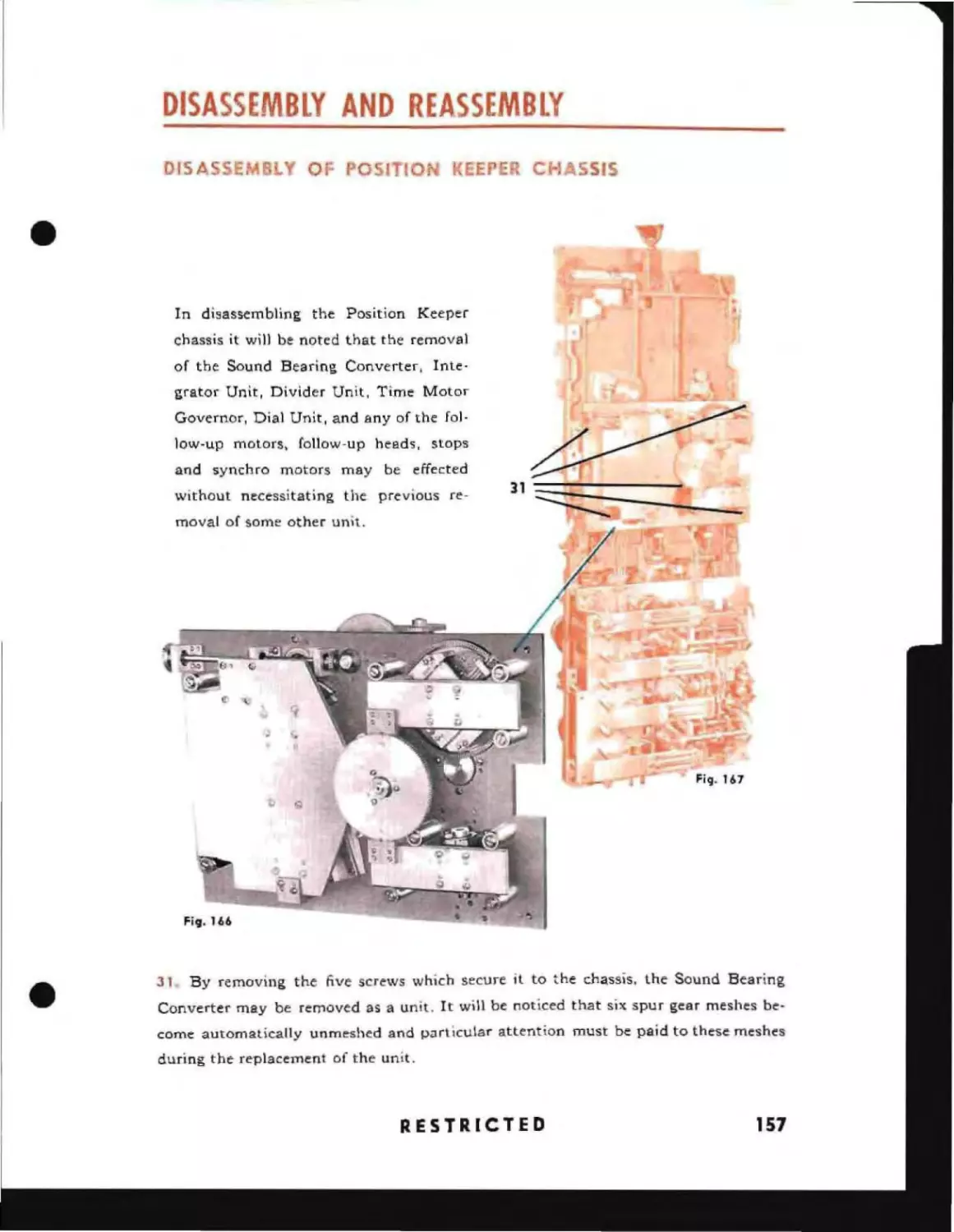
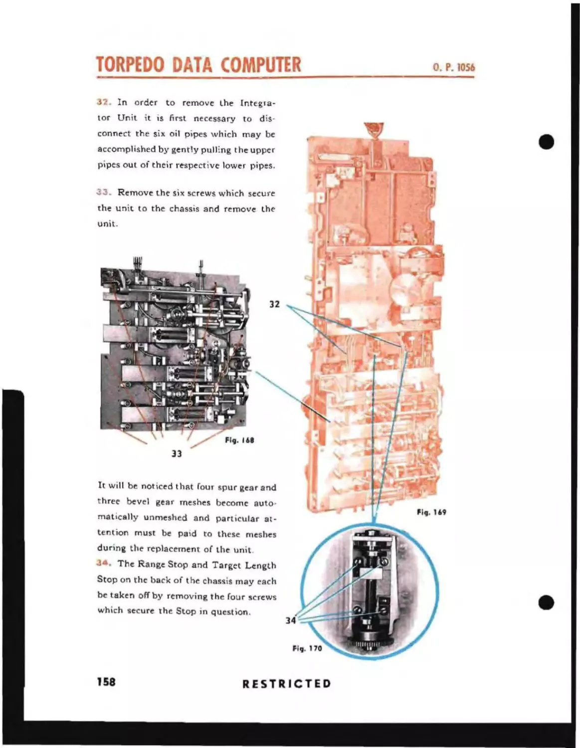
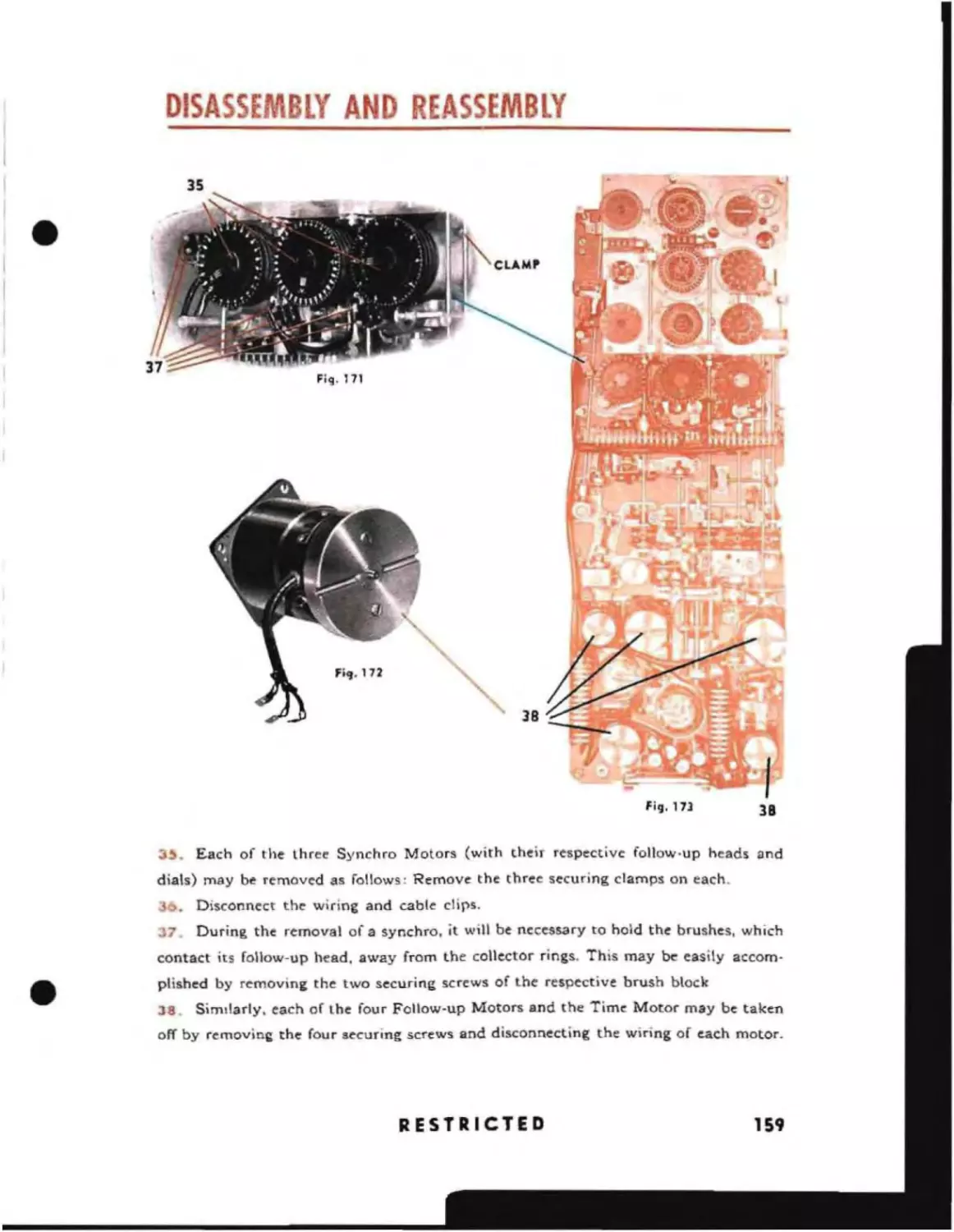
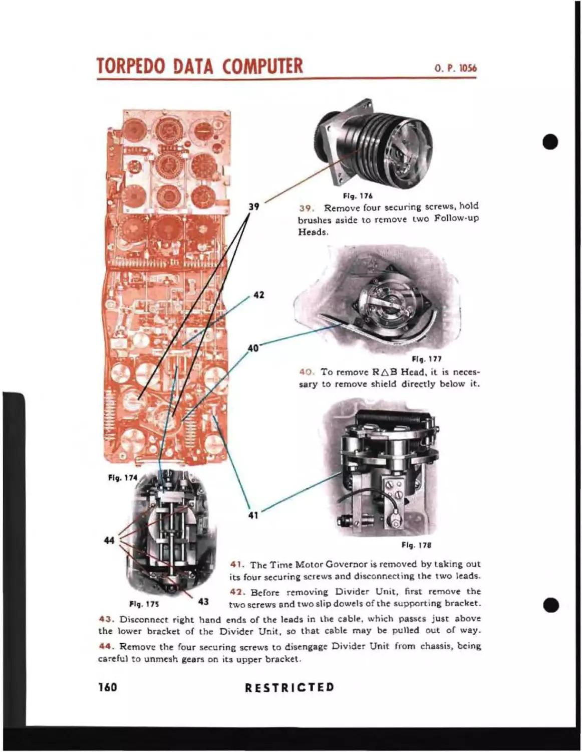
Disassembly of Position Keeper Chassis
Disassembly of Angle Solver Chassis
Reassembly of Position Keeper .
Reassembly of the Angle Solver
Securing the Sections in Place
O'
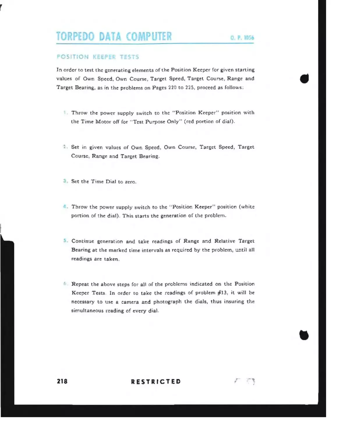
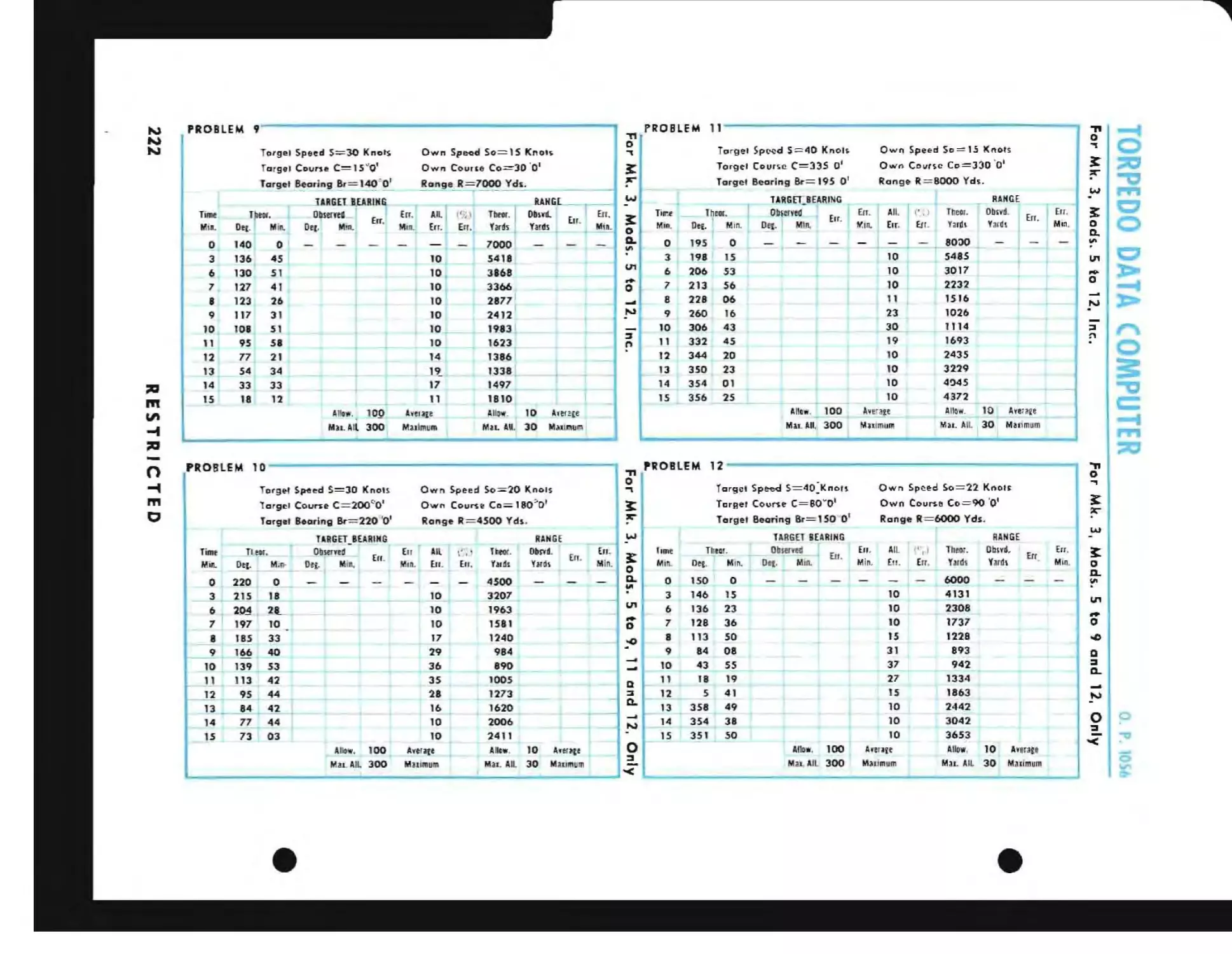
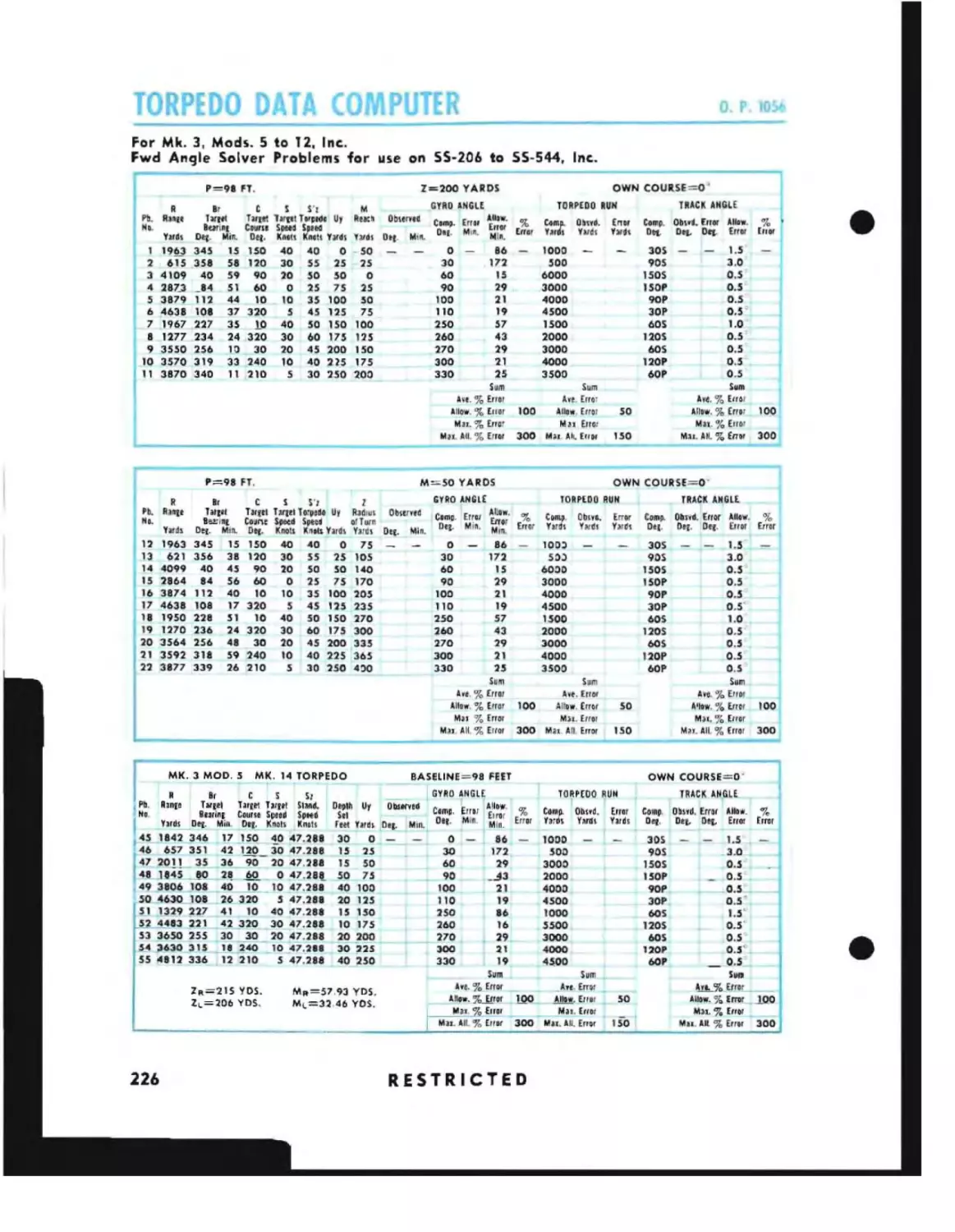
Position Keeper Tests
For Mk. 3, Mods. 5 to 12, Inc.
6
97A
100
104
104
Position Keeper Section
'-C
85
86A
87
157
163
170
186
204
217
218
220
RESTRICTED
_
;:cc
T 8lE Of (ONTENTS
SECTION b- T~,,.
Cl)ntinl,l"d
For Mk. 3, Mods. 5-9, 11 and 12, only
For Mk. 3, Mods. 5-9 and 12, only
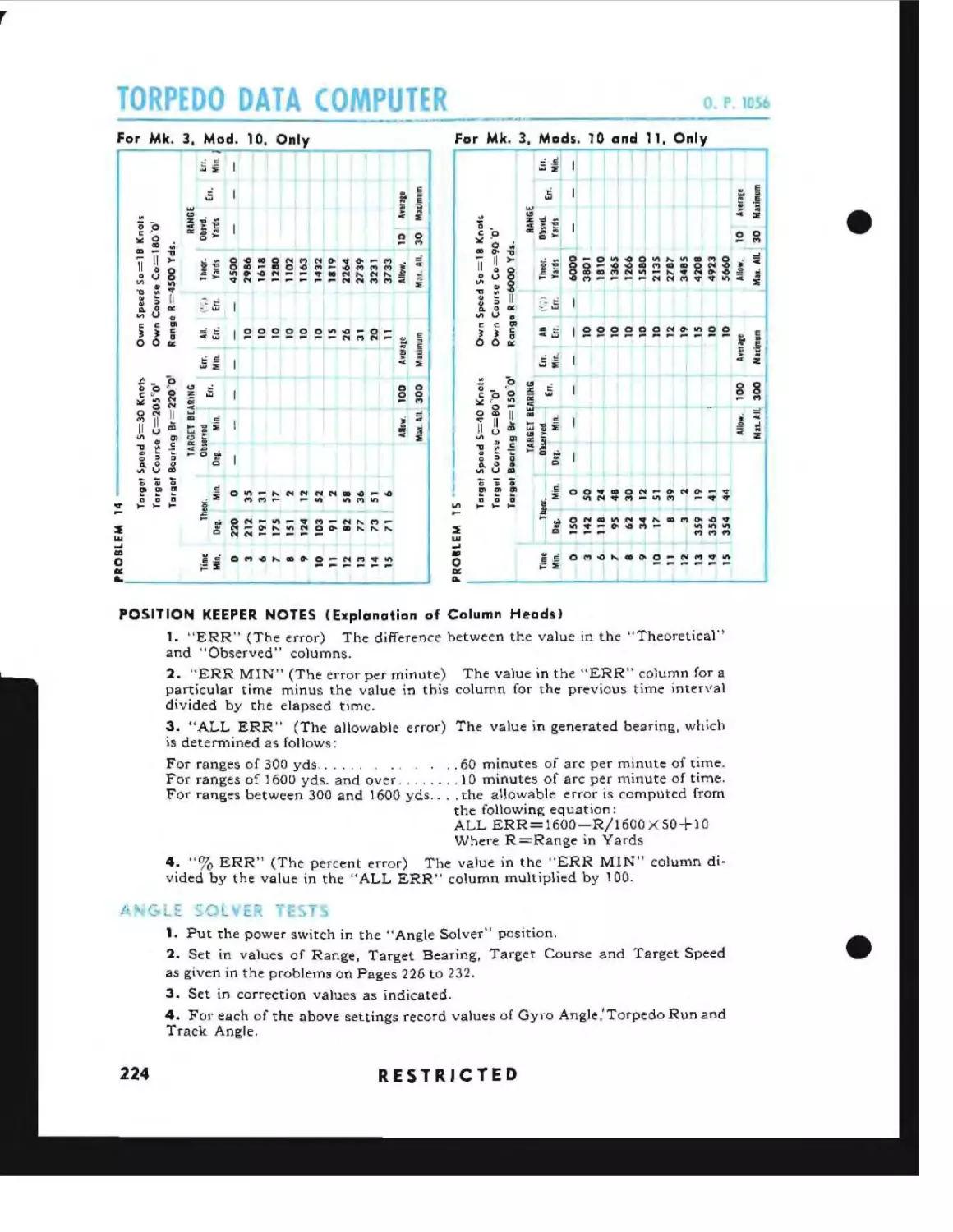
For Mk. 3, Mod. 10, only
For Mk. 3, Mods. 10 and 11, only
Position Keeper Notes
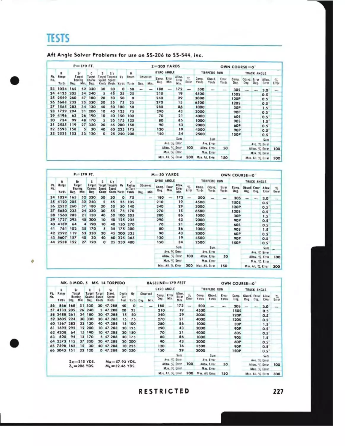
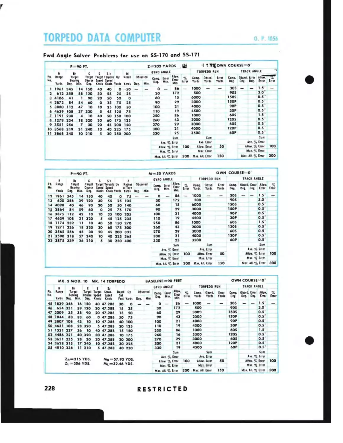
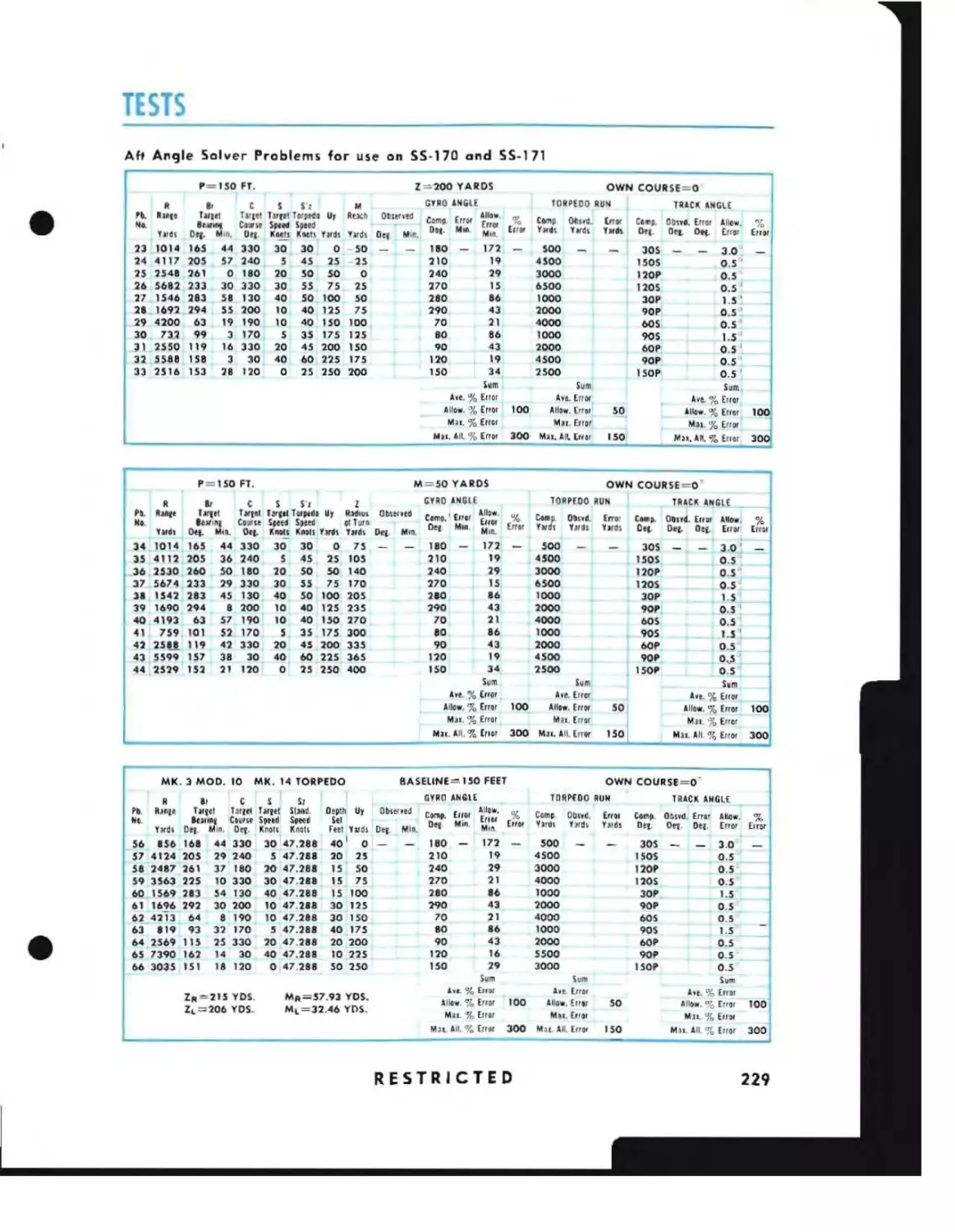
Angle Solver Tests
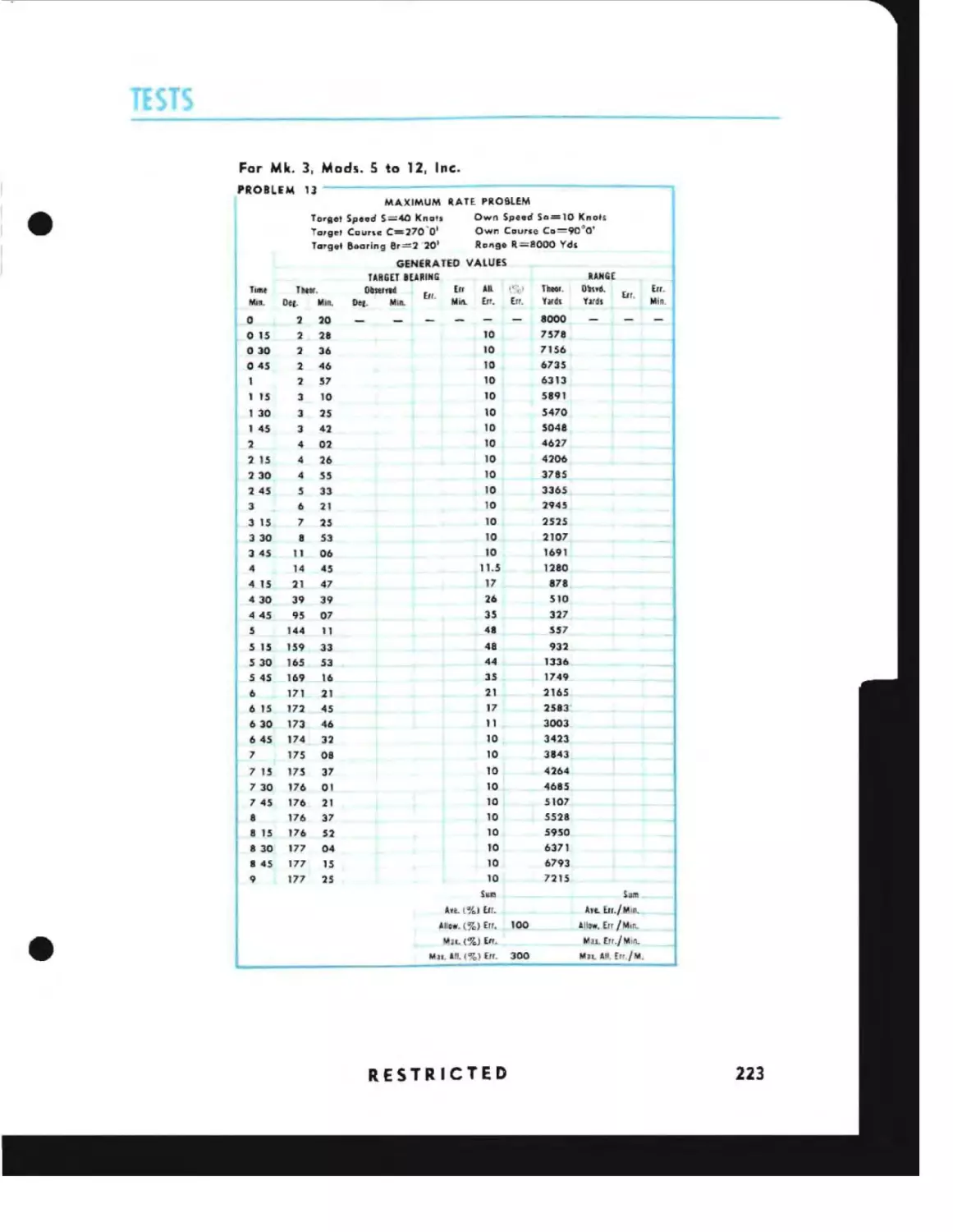
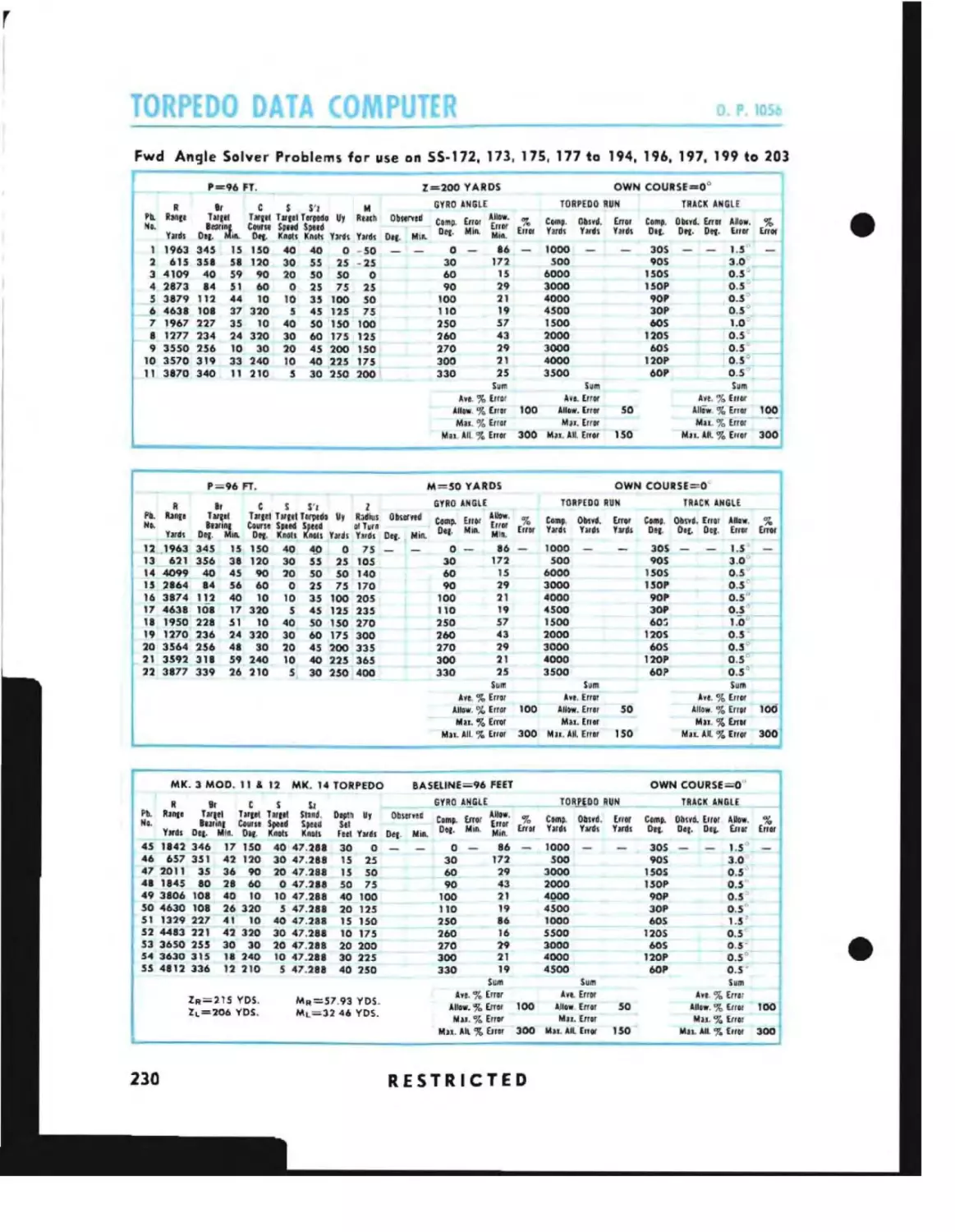
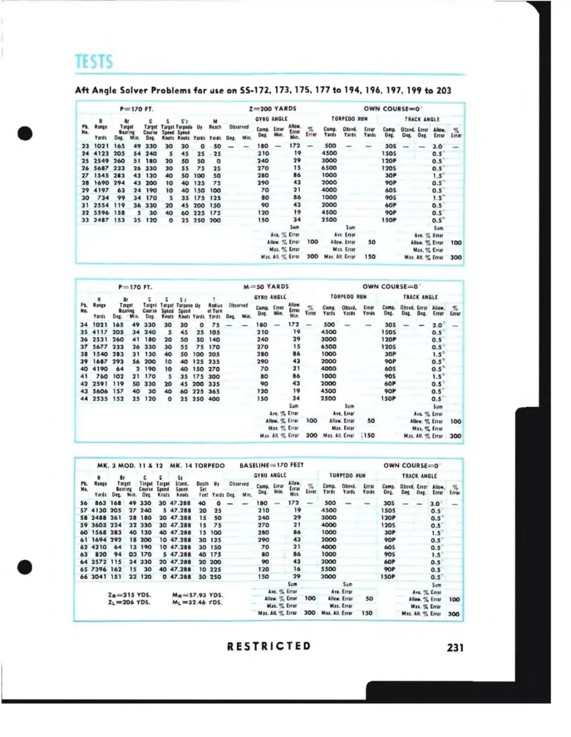
For Mk. 3, Mods. 5 to 12. Inc.
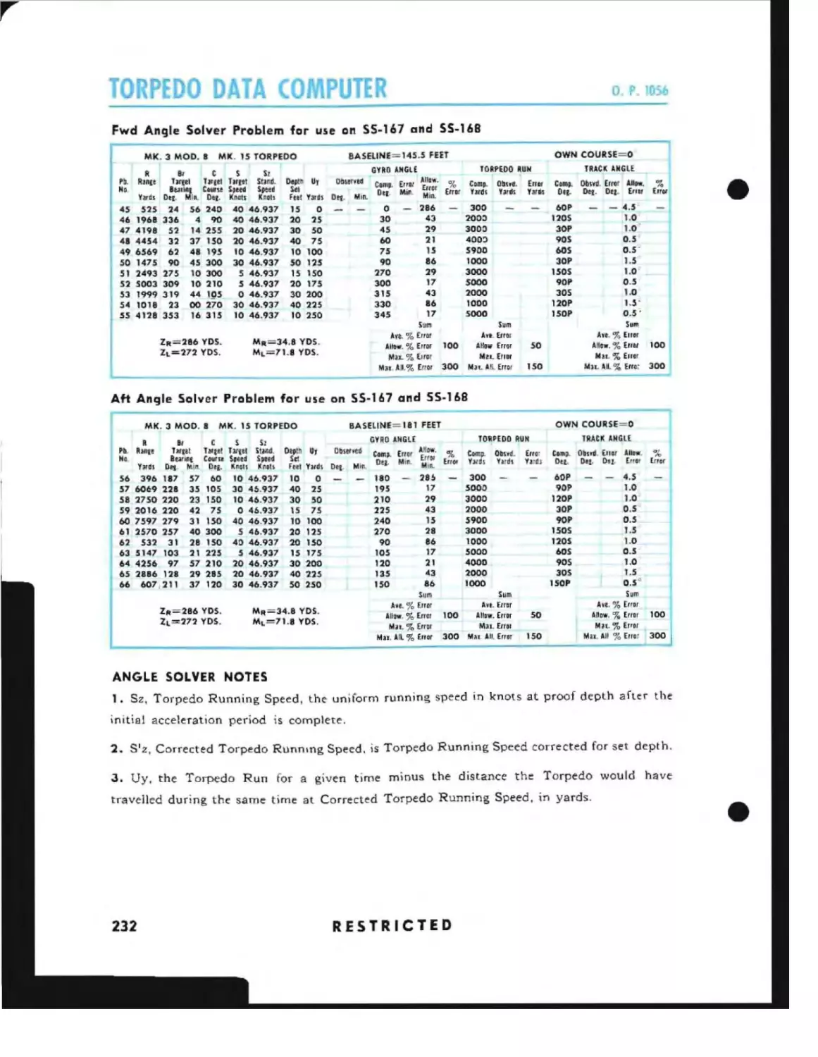
Angle Solver Notes
Sound Bearing Converter Tests.
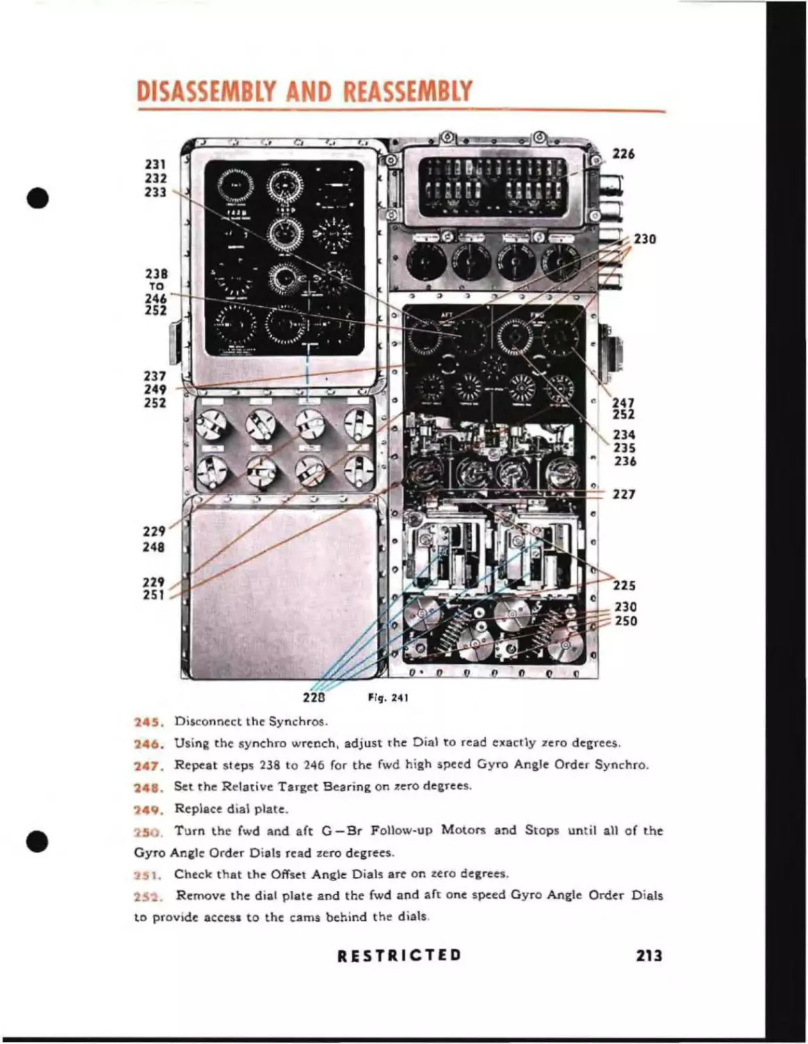
Sound Bearing Converter Note
HCTIO~~
7
IfutQll<ltion
SEC TlO N B-Adfu ,t"h'nL
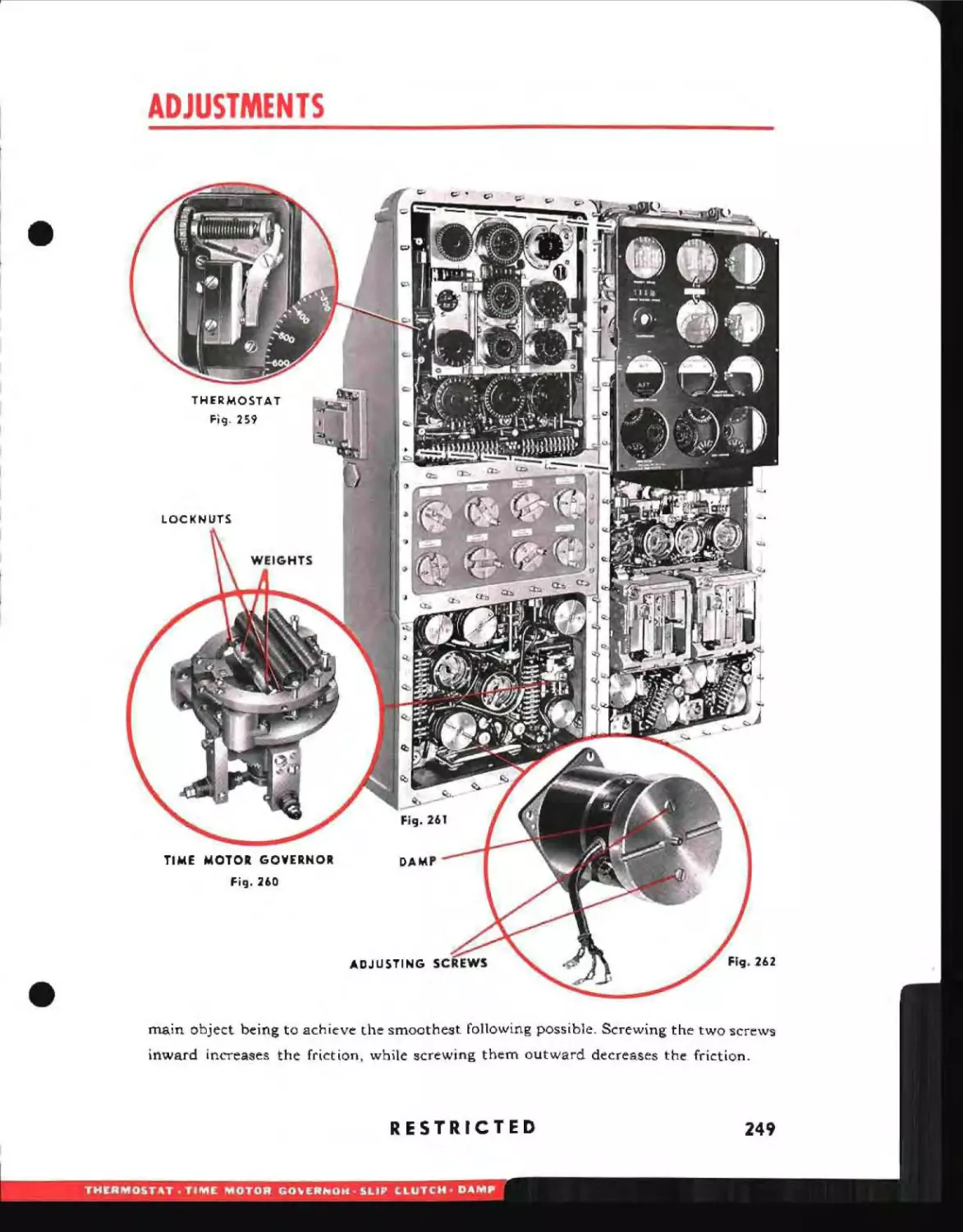
Thermostat
Time Motor Governor
Slip Clutches
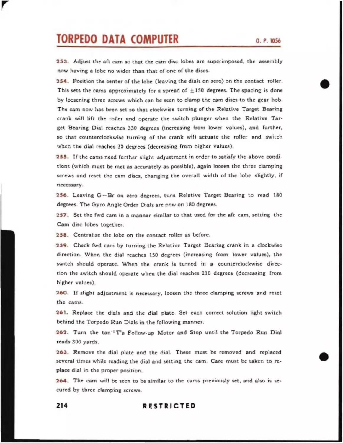
Follow-up Motor Damps
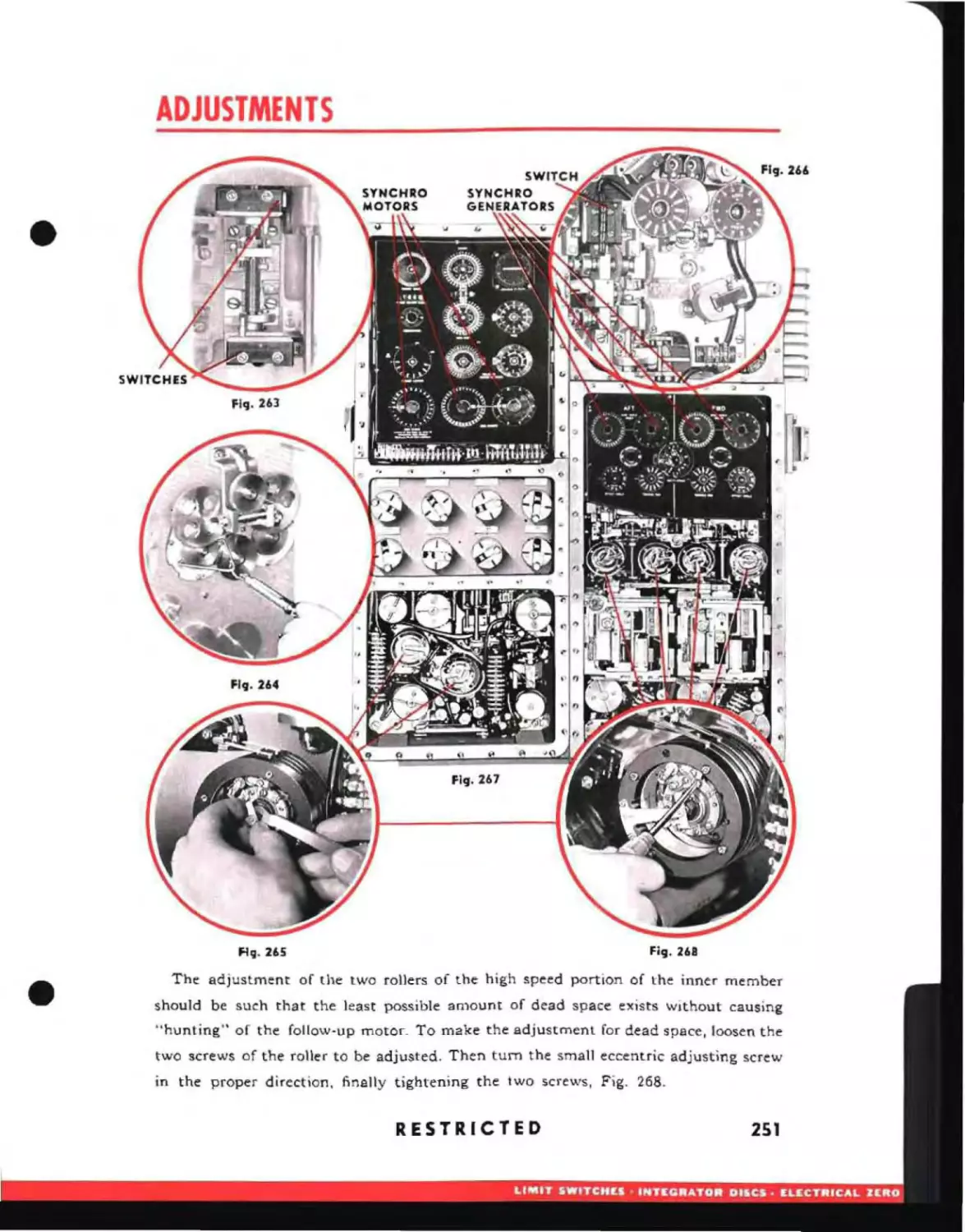
Angle Solver Range Stop Switches
Offset Angle Zero Detent Switches
Integrator Unit and Divider Unit Discs
Synchro Motor and Generator Electrical Zero
Mechanical Follow-up Heads
Correct Solution Light Switches
Dials
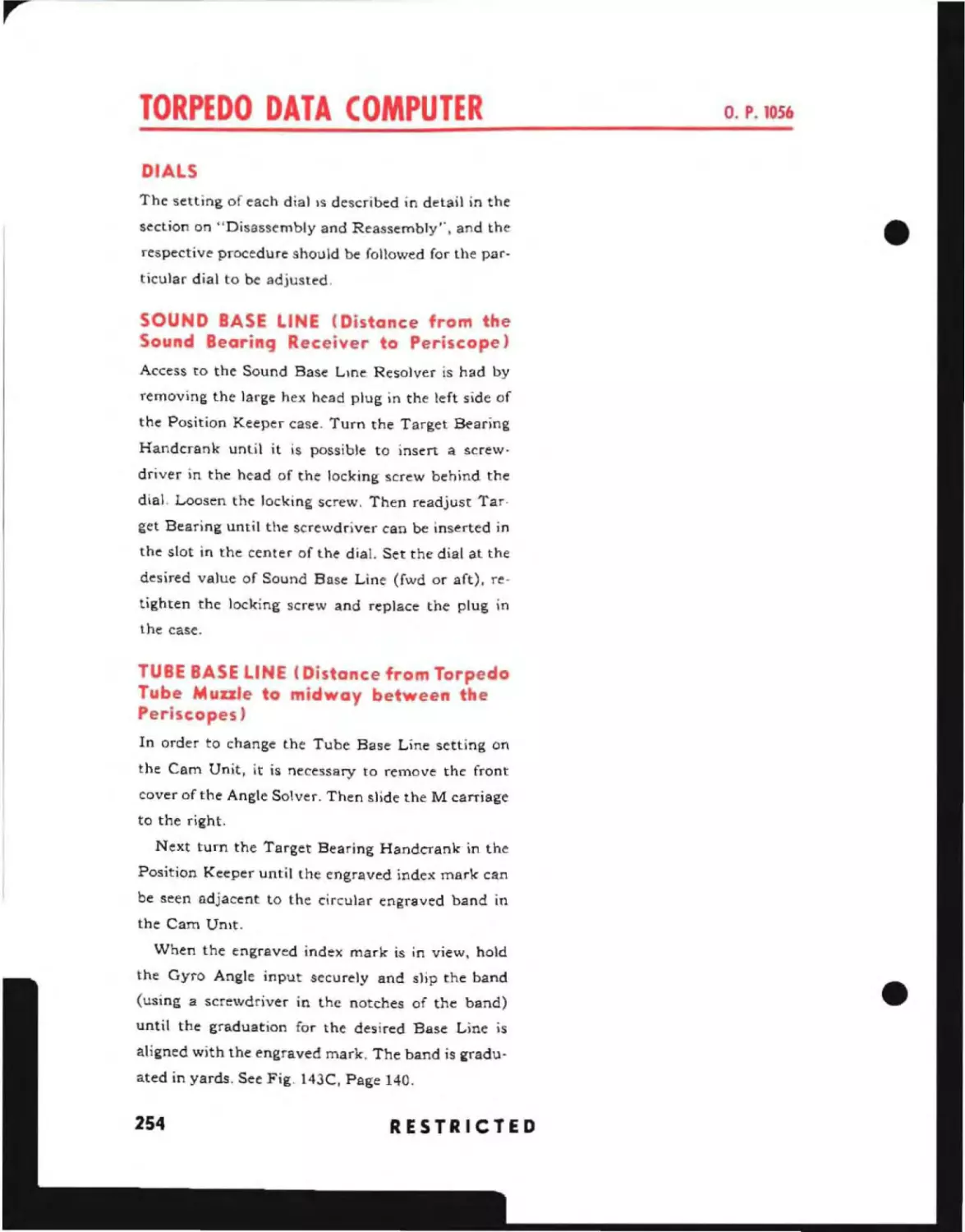
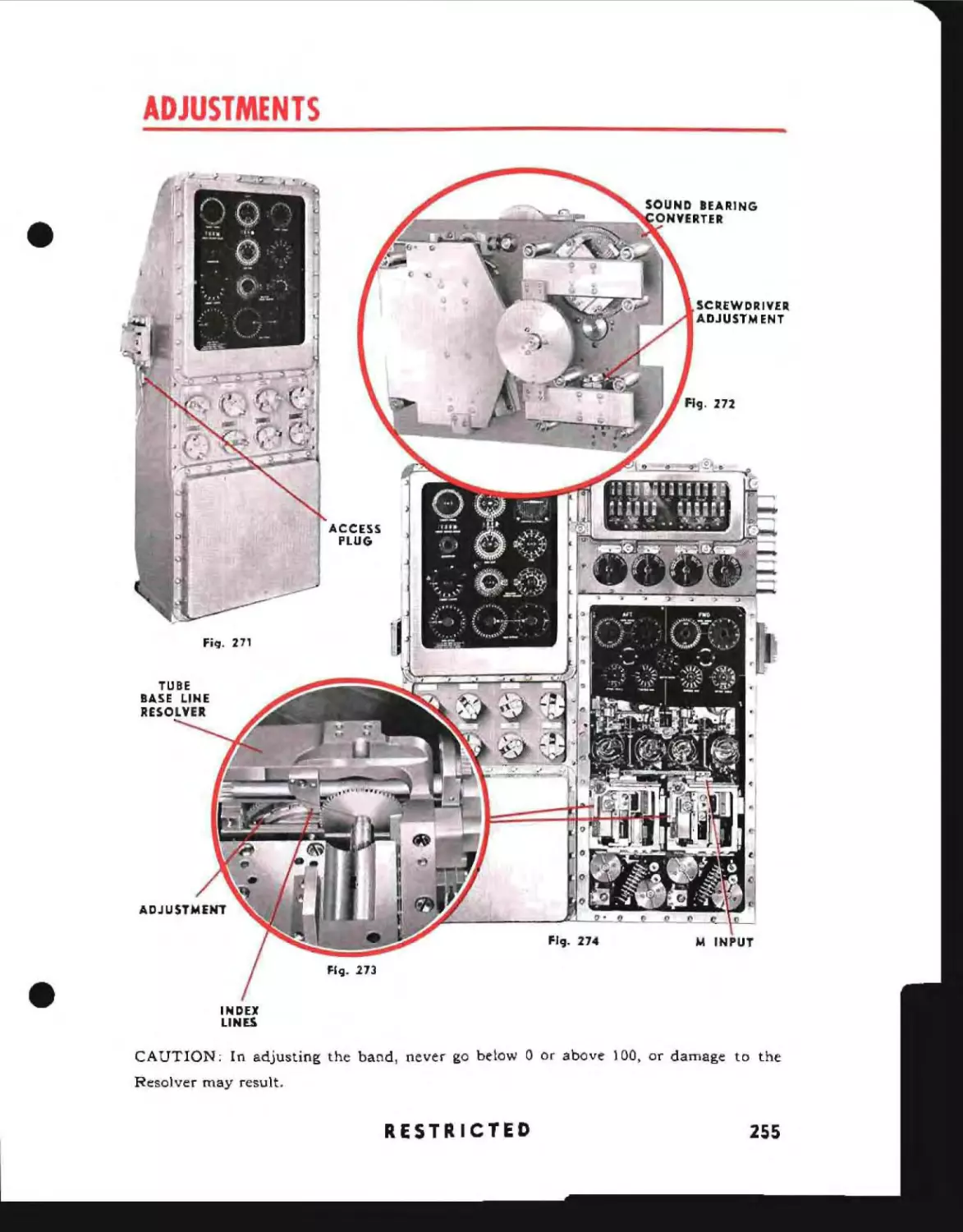
Sound Base Line .
Tube Base Line
Cam Unit Settings
Replacing Uy and M Knob Dials
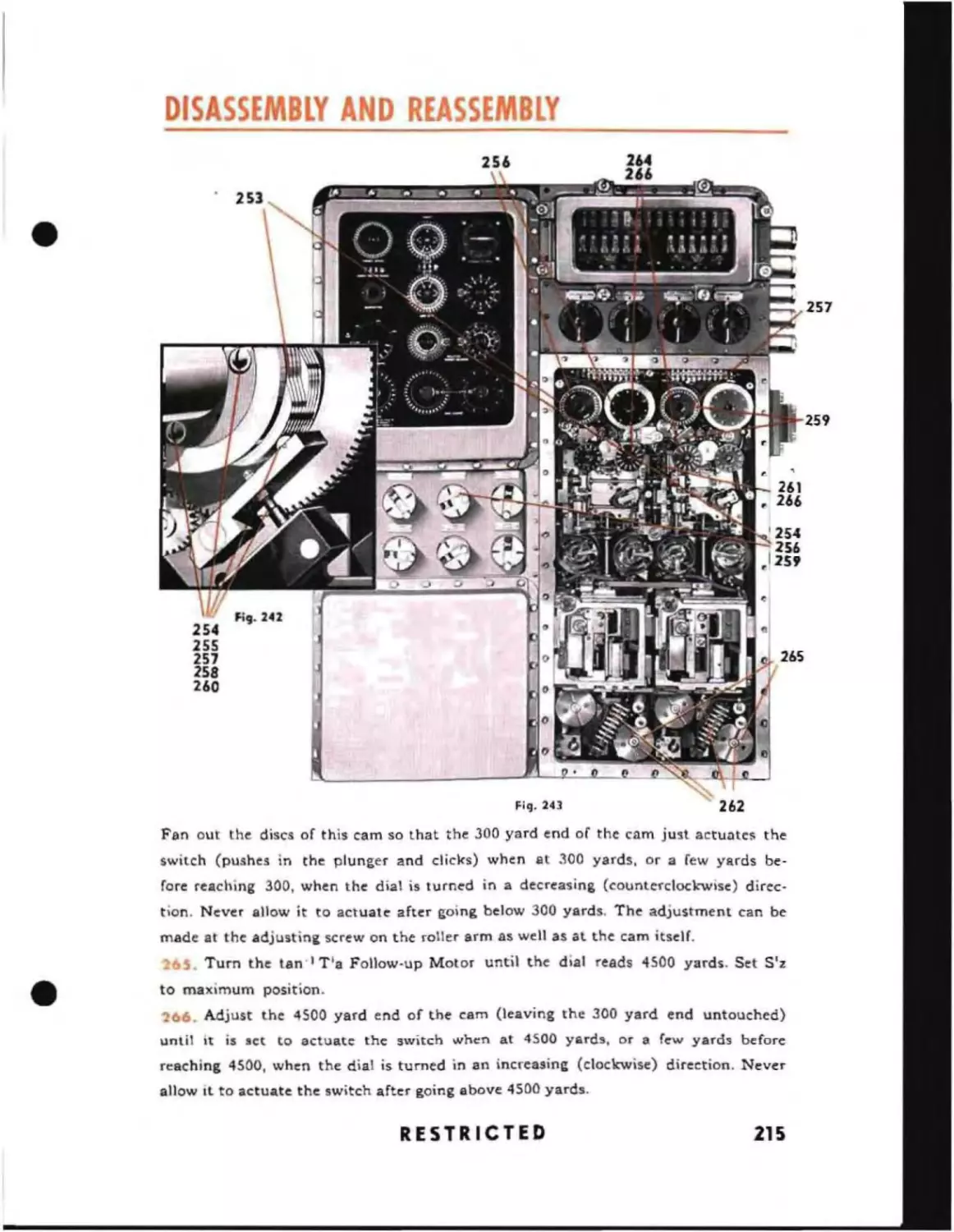
Replacing Angle Solver Front Cover
5!:'CT!O~1
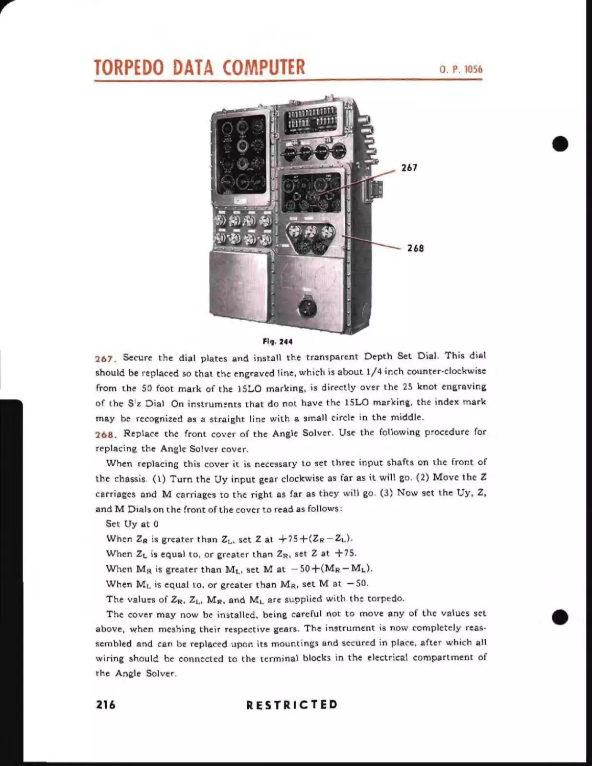
')
r!o':
10
/\'-.~
'nci,
233
235
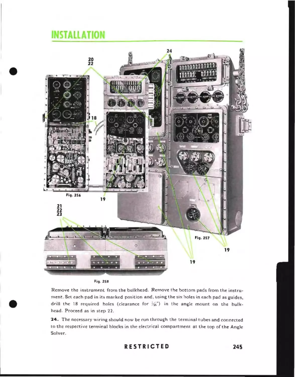
247
248
248
248
248
250
250
250
250
250
252
254
254
254
256
256
256
259
lub,·;cati"'ll
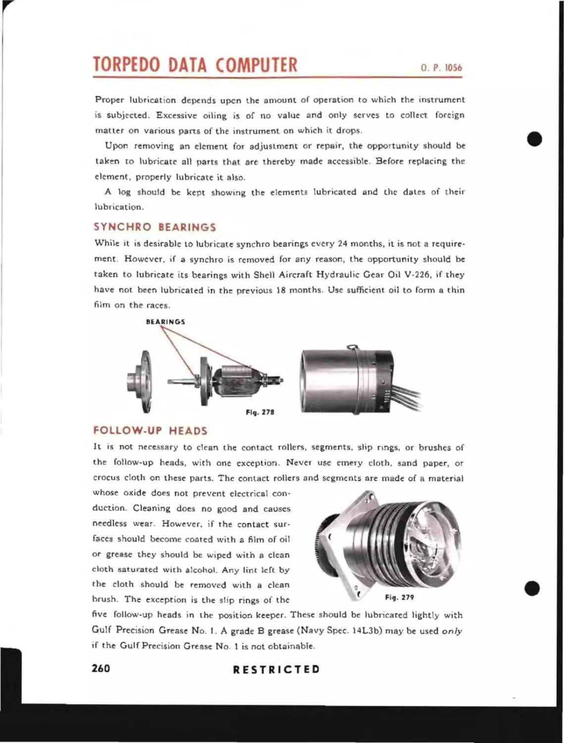
Synchro Bearings .
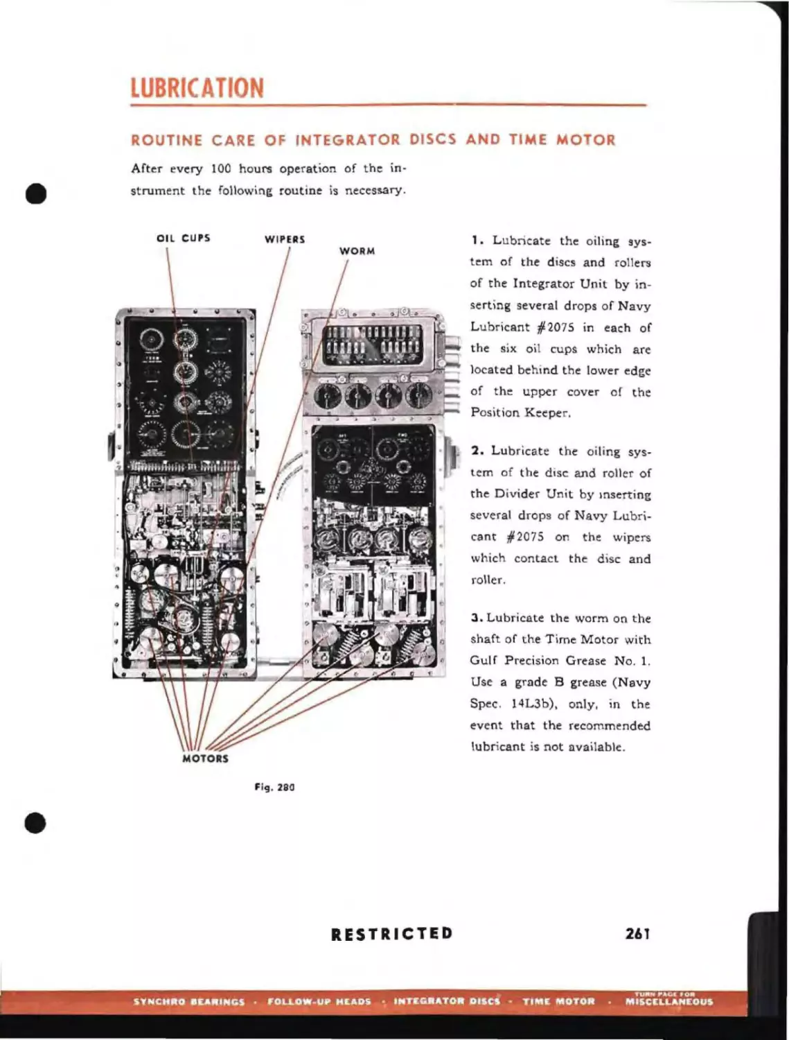
Follow-up Heads
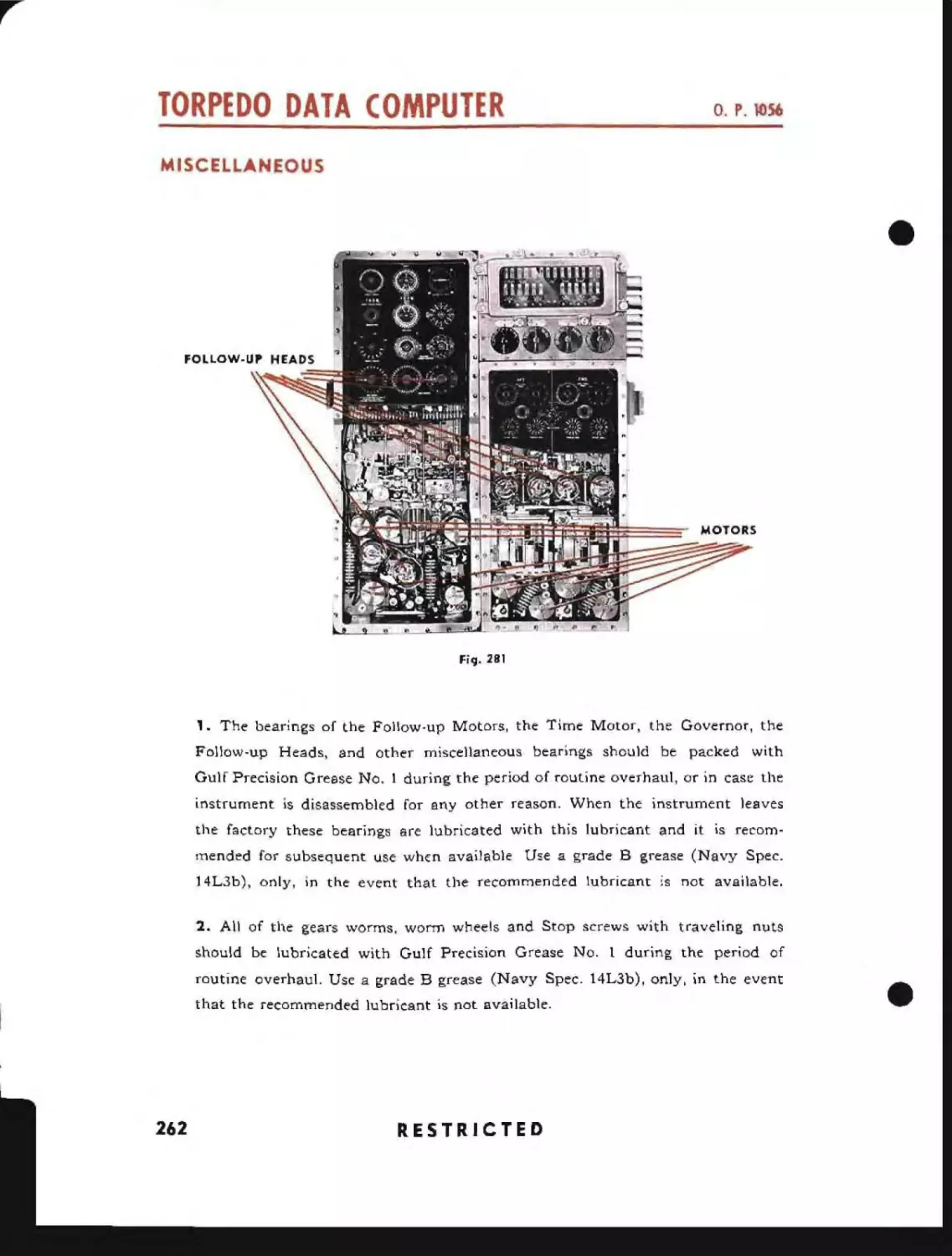
Integrator Discs and Time Motor
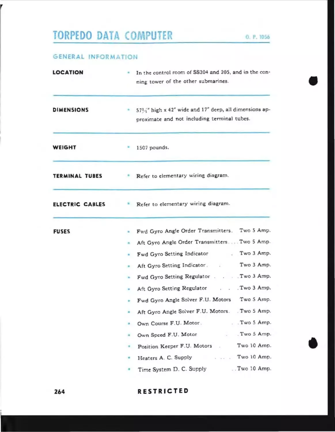
Miscellaneous
s~c
222
222
224
224
224
224
226
232
233
_
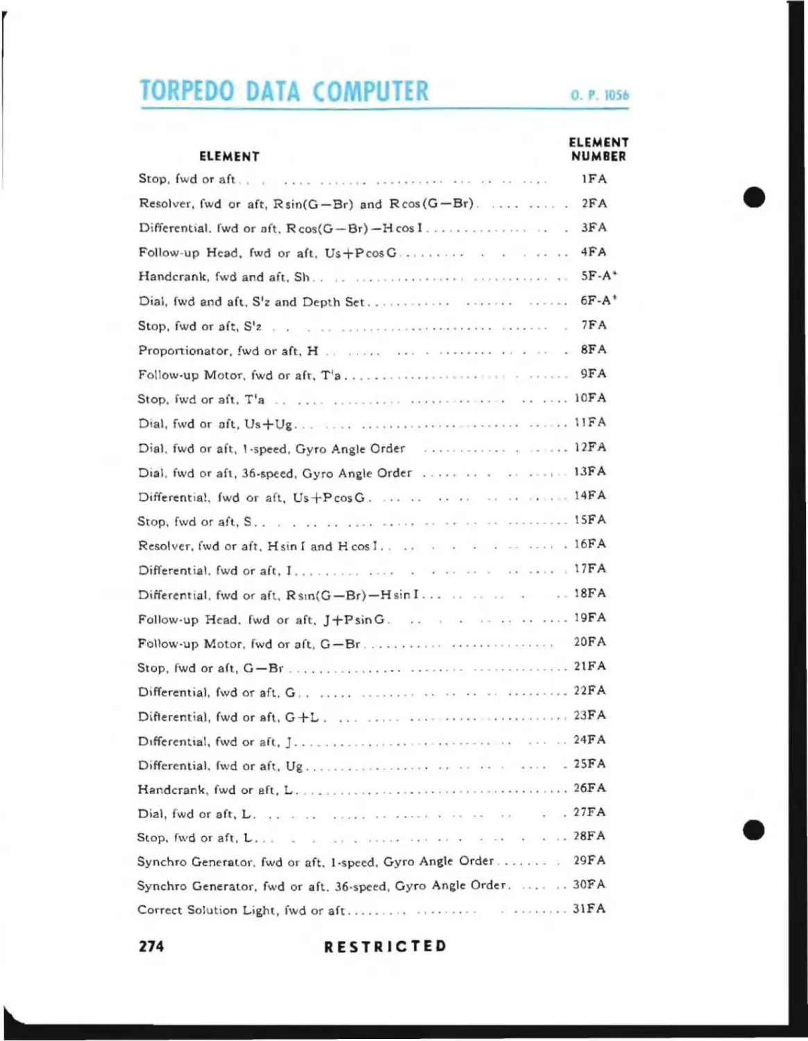
General Information
Inputs and Outputs
Dial and Counter Graduations
Relative Speeds
Principal Drawings
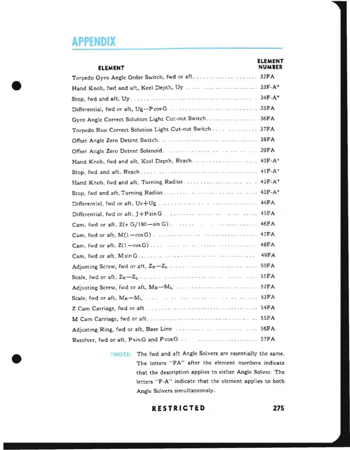
Element Numbers
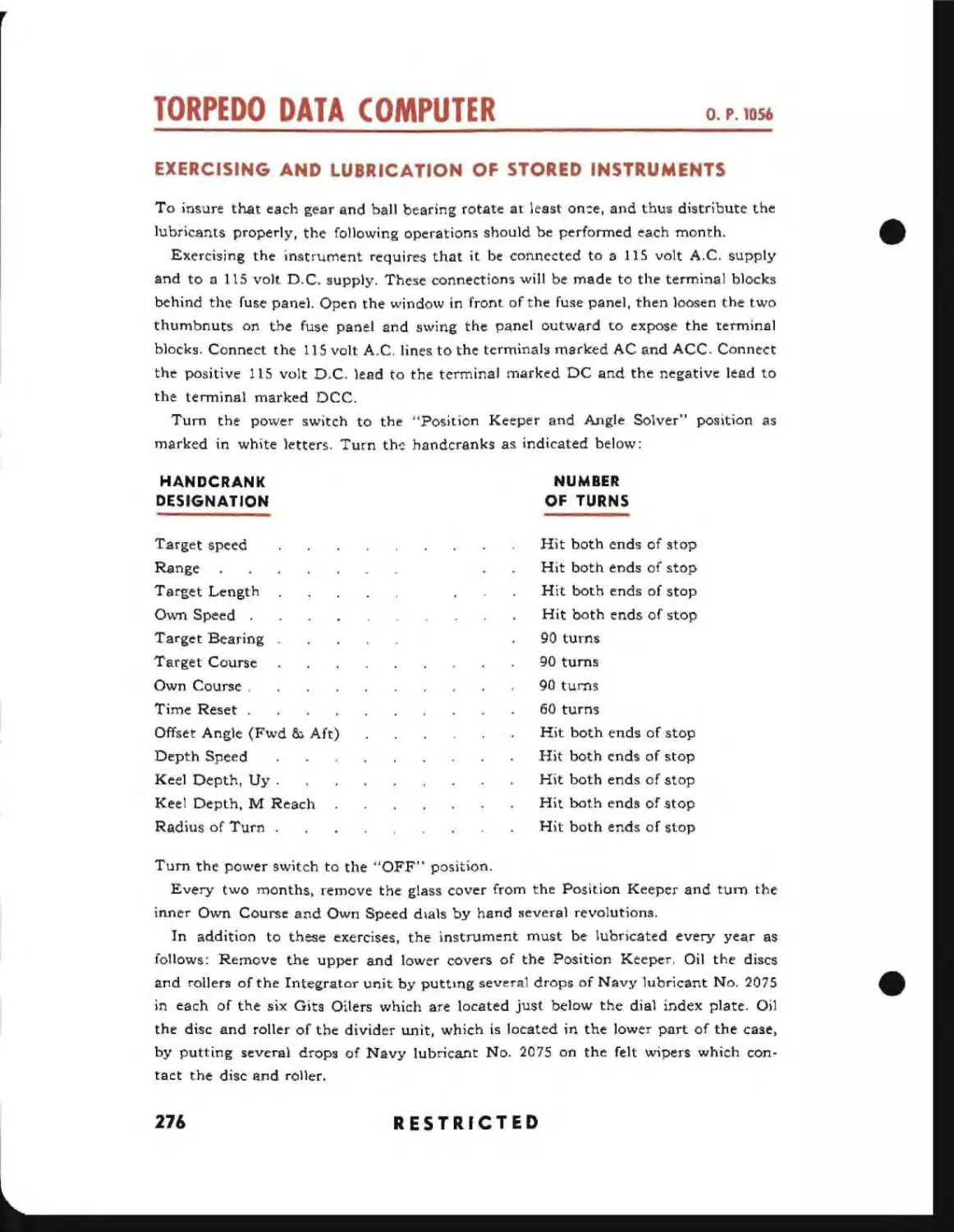
Exercising Stored Instruments
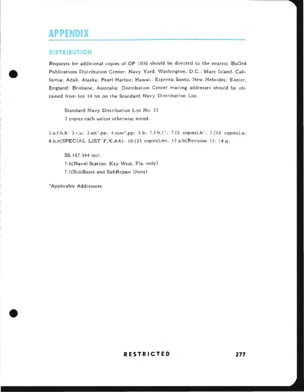
Distribution List .
RESTRICTED
260
260
261
262
263
264
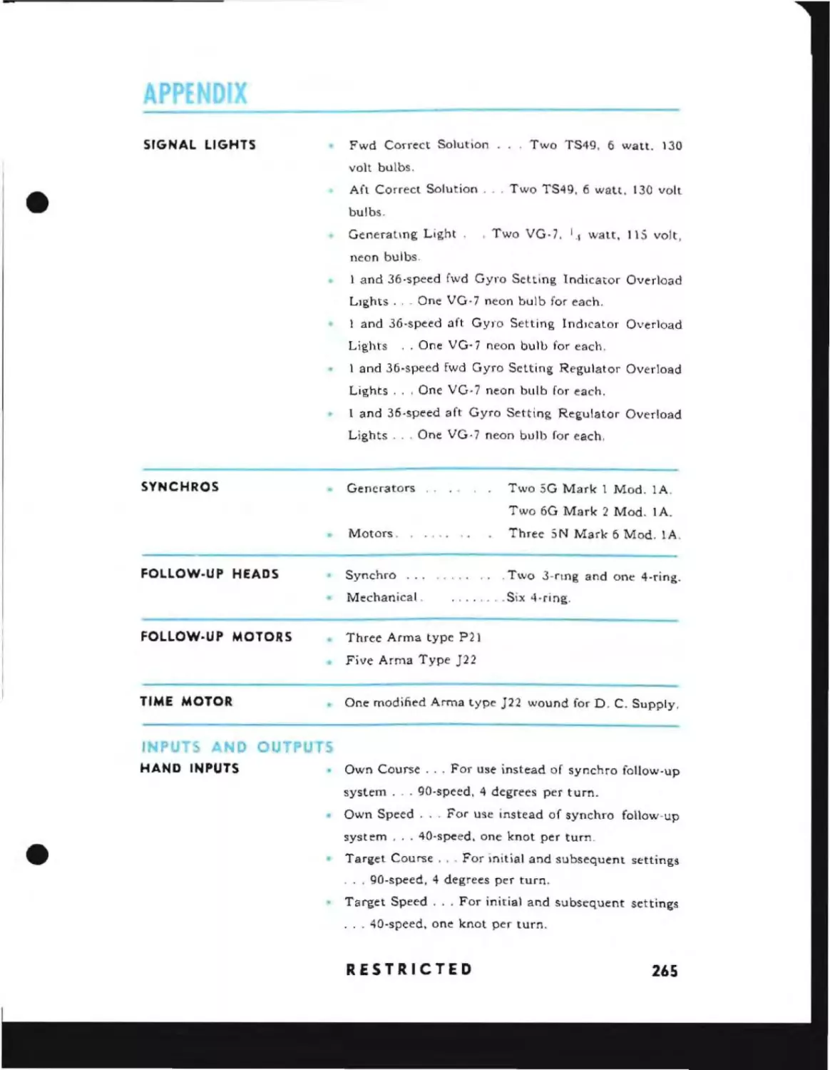
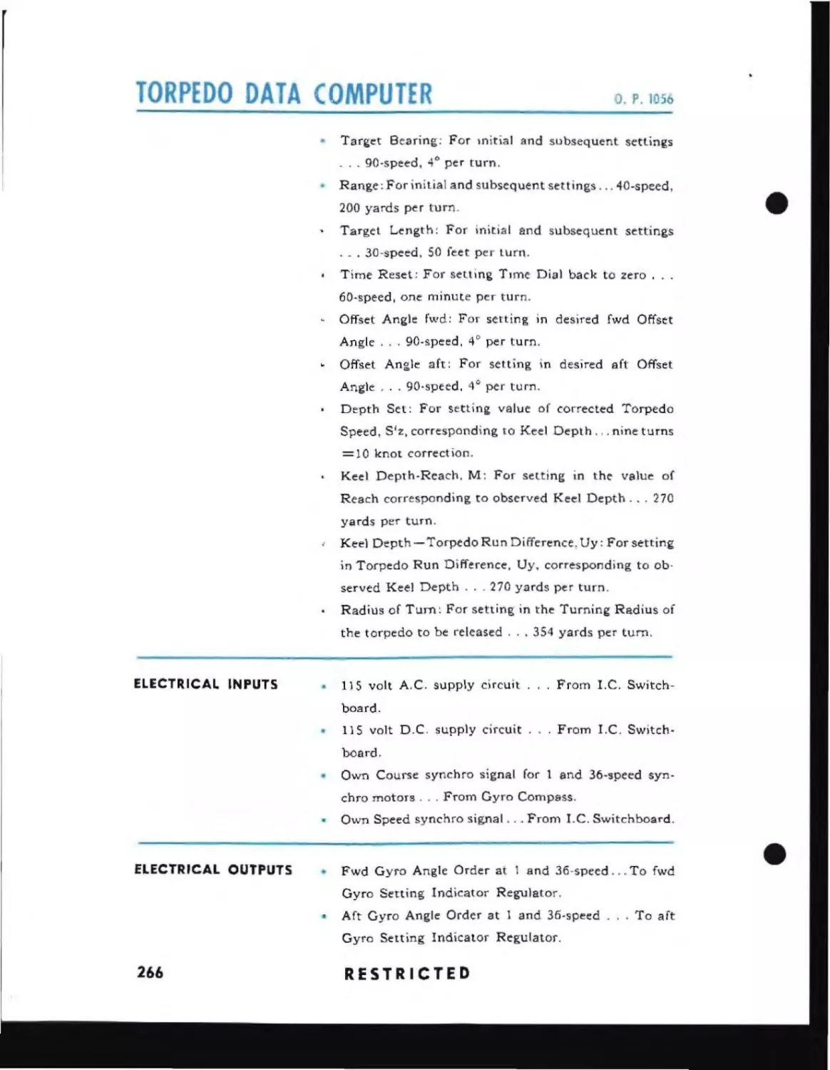
265
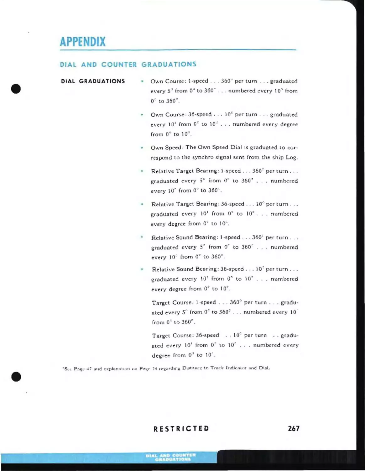
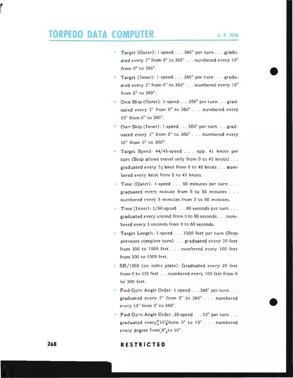
267
271
271
272
276
277
7
_ _ _ _ _ _ _ _ _ _ _ _ _ _ _ _ _ _.4
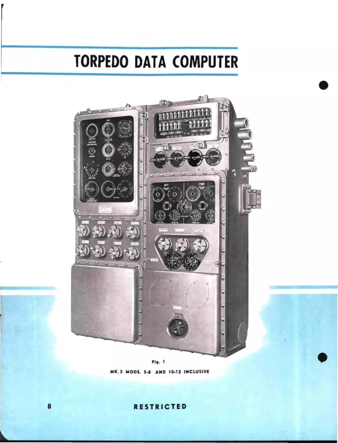
TORPEDO DATA COMPUTER
•
Fig. 1
MK.3 MODS. 5.8
8
AND 10.12 INCLUSIVE
RESTRICTED
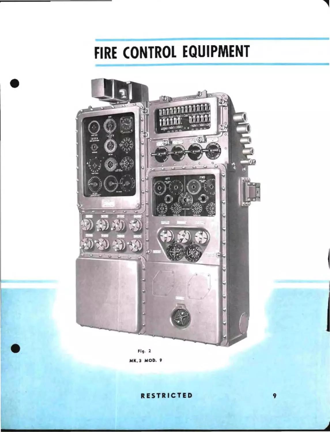
FIRE CONTROL EQUIPMENT
FIg. 2
MK.3 MOD. 9
RESTRICTED
iiIIIIIIIIIIIII........--....i
.....i..-
9
..
•
ANALYSIS
OF FIRE CONTROL PROBLEM
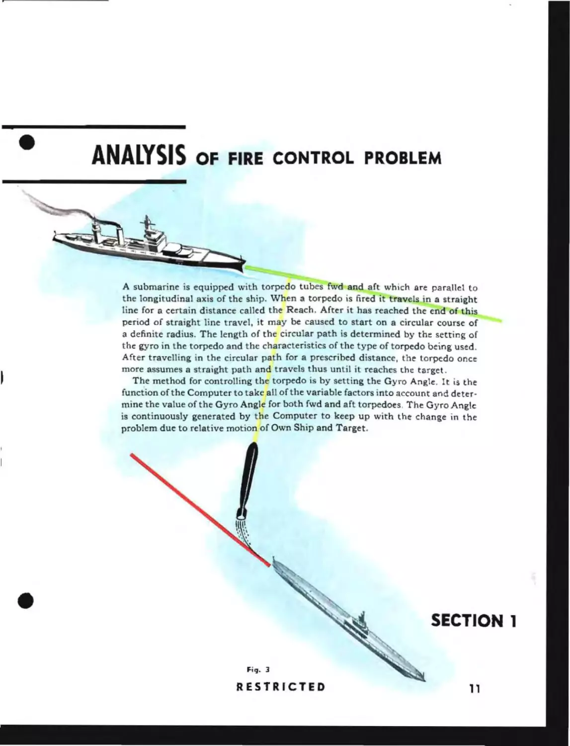
A submarine is equipped with torpedo tubes fwd and aft which are parallel to
the longitudinal axis of the ship. When a torpedo is fired it travels in a straight
line for a certain distance called the Reach. After it has reached the end of this
period of straight line travel, it may be caused to start on a circular course of
a definite radius. The length of the circular path is determined by the setting of
the gyro in the torpedo and the characteristics of the type of torpedo being used.
After travelling in the circular path for a prescribed distance, the torpedo once
more assumes a straight path and travels thus until it reaches the target.
The method for controlling the torpedo is by setting the Gyro Angle. It is the
function of the Computer to take all of the variable factors into account and determine the value of the Gyro Angle for both f~d and aft torpedoes. The Gyro Angle
is continuously generated by the Computer to keep up with the change in the
problem due to relative motion of Own Ship and Target.
SECTION 1
F;q. 3
RESTRICTED
11
TORPEDO DATA COMPUTER
o. P.l056
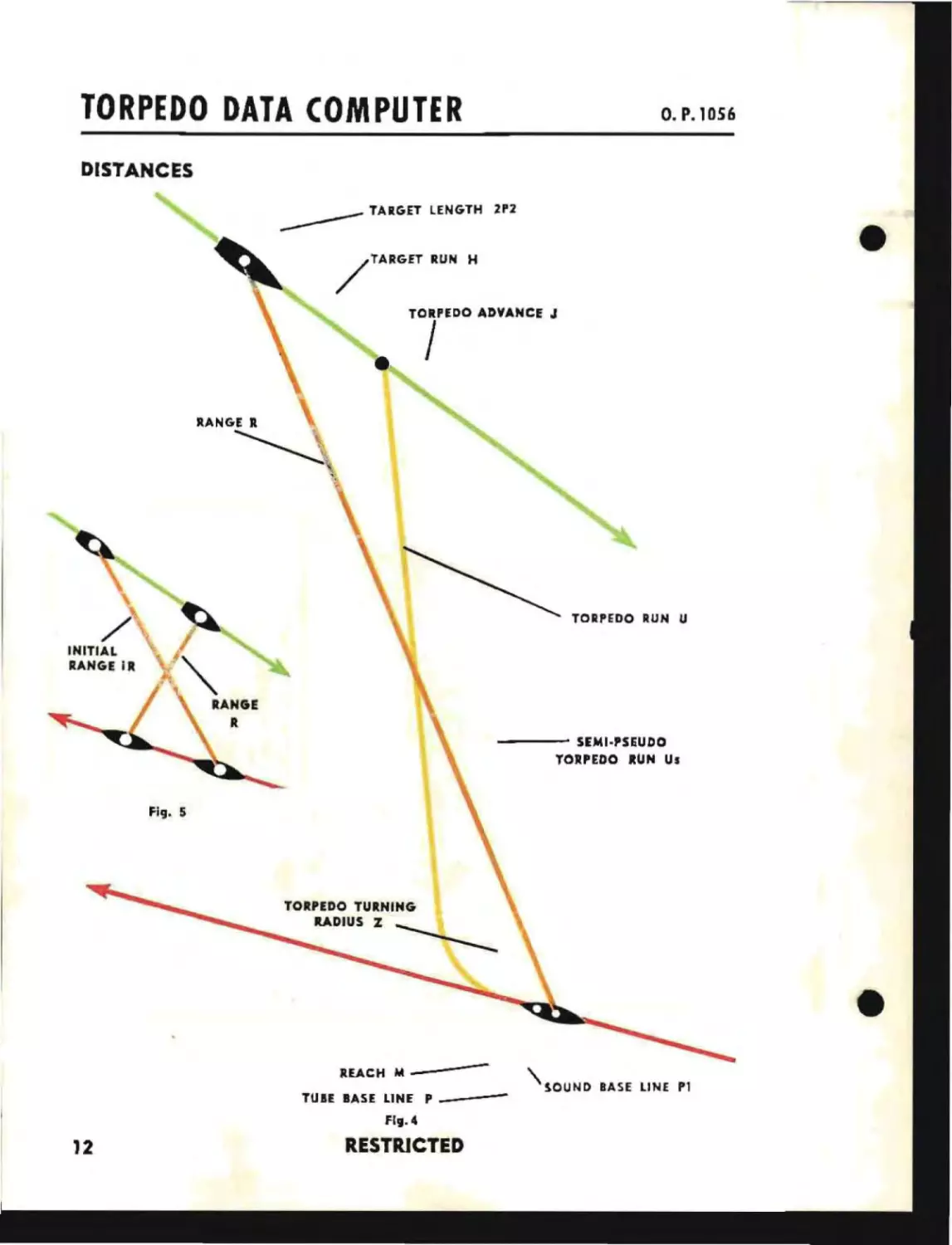
DISTANCES
_ _ _ _ _ TARGET LENGTH
/
2P2
TARGET RUN H
RANGE R
~ ...
,
TORPEDO RUN U
- - - - SEMI·PSEUDO
TORPEDO RUN Us
Fig. 5
REACH 1It\SOUND BASE LINE P1
TUIE BASE LINE P_
----
flg.4
12
RESTRICTED
•
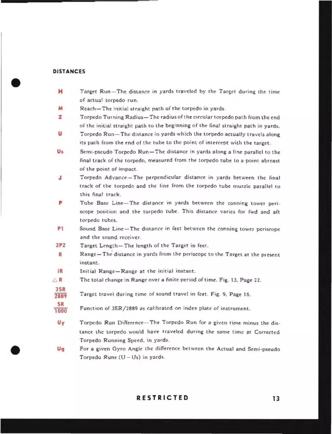
DISTANCES
H
Target Run-The distance in yards traveled by the Target during the time
of actual torpedo run.
M
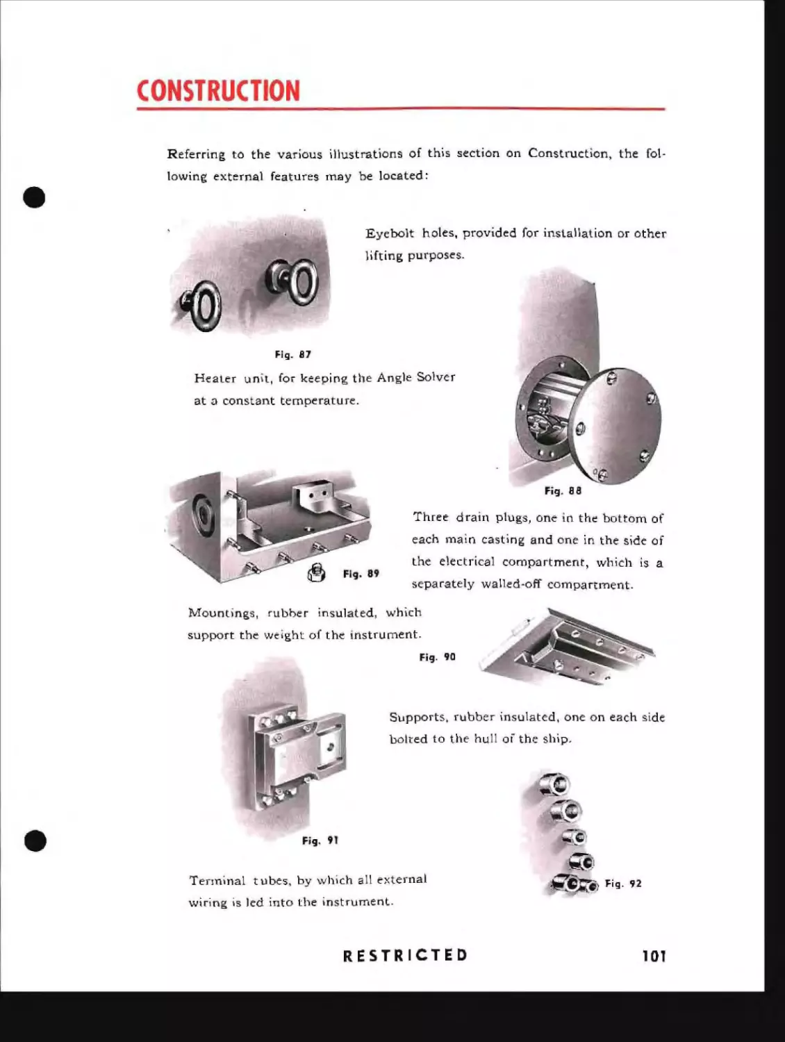
Reach-The initial straight path of the torpedo in yards.
Z
Torpedo Turning Radius- The radius of the CIrcular torpedo path from the end
of the initial stfaight path to the beginning of the final straight path in yards.
u
Torpedo Run-The distance in yards which the torpedo actually travels along
its path from the end of the tube to the point of intercept with the target.
Us
Semi-pseudo Torpedo Run-The distance in yards along a line parallel to the
final track of the torpedo, measured from the torpedo tube to a point abreast
of the point of impact,
J
Torpedo Advance-The perpendicular distance in yards between the final
track of the torpedo and the line from the torpedo tube muzzle parallel to
this nnal track.
p
Tube Base Line-The distance in yards between the conning tower periscope position and the torpedo tube. This distance varies for fwd and aft
torpedo tubes.
Pl
Sound Base Line-The distance in feet between the conning tower periscope
and the sound receiver.
2P2
R
Target Length-The length of the Target in feet.
Range-Th~distance in yards from the periscope to the Target at the present
instant.
jR
L,R
Initial Range-Range at the initial instant.
The total change in Range over a finite period of time. Fig. 13, Page 22.
3SR
2889
Target tfDvel during time of sound travel in feet. Fig. 9, Page 16.
SR
1000
Function of 3SRj2889 as calibrated On index plate of instrument.
Uy
Torpedo Run Difference-- The Torpedo Run for a given time minus the distance the torpedo would have traveled during the same time at Corrected
Torpedo Running Speed, in yards.
Ug
For a given Gyro Angle the difference between the Actual and Semi-pseudo
Torpedo Runs (U - Us) in yards,
RESTRICTED
13
TORPEDO DATA COMPUTER
O. P. lOS'
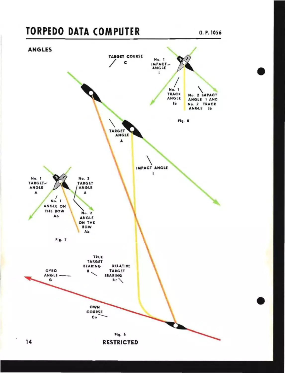
ANGLES
TARGET COURSE
/
'l~
-.-
"
No. t
IMPACT _
ANGLE
I
c
rt'
/
No.1
TUCK
ANGLE
Ib
~G~
ANZL~
F1':I' I
A
\
IMPACT ANGLE
I
No. t
TARGET....
ANGLE
A
No.2
TARGET
/
No. t
ANGLE ON
THE BOW
Ab
(:LE
No.2
ANGLE
ON THE
lOW
Ab
F-11.l. 7
TRUE
TARGET
BEARING
GYRO
ANGlE_
G
.,
RELATIVE
TARGET
IEARING
B r '\.
Fig. II
14
RESTRICTED
\
No.2 IMPACT
ANGLE I AND
No.2 TRACK
ANGLE
Ib
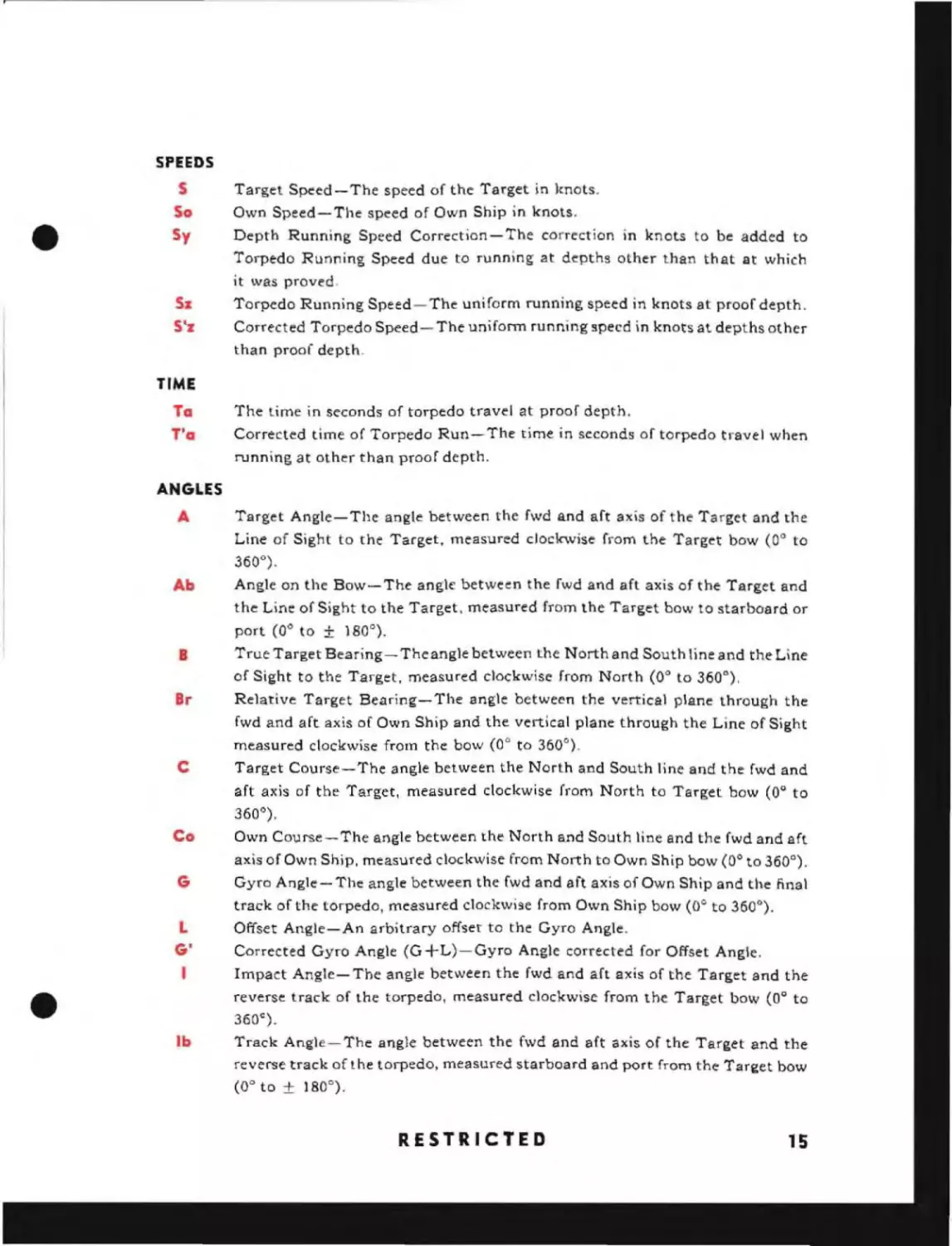
SPEEDS
S
So
Sy
Target Speed-The speed of the Target in knots.
Own Speed-The speed of Own Ship in knots.
Depth Running Speed Correction-The correction
10
knots to be added to
Torpedo Running Speed due to running at depths other than that at which
5z
S'z
it was proved.
Torpedo Running Speed- The uniform running speed in knots at proof depth.
Corrected Torpedo Speed- The unifonn running speed in knots at depths other
than proof depth.
TIME
To
T'a
The time in seconds of torpedo travel at proof depth.
Corrected time of Torpedo Run- The time in seconds of torpedo travel when
running at other than proof depth.
ANGLES
A
Target Angle- The angle between the fwd and aft axis of the Target and the
Line of Sight to the Target. measured clockwise from the Target bow (0 0 to
360 0 ) .
Ab
Angle on the Bow- The angle between the fwd and aft axis of the Target and
the Line of Sight to the Target. measured from the Target bow to starboard or
port (0 0 to
±
180 0 ).
B
True Target Bearing- Theang1e between the North and South line and the Line
of Sight to the Target, measured clockwise from North (0 0 to 360°),
Br
Relative Target Bearing- The angle between the vertical plane through the
fwd and aft axis of Own Ship and the vertical plane through the Line of Sight
measured clockwise from the bow (0 0 to 360°).
c
Target Course-The angle between the North and South line and the fwd and
aft axis of the Target, measured clockwise from North to Target bow (0° to
360°).
Co
Own Course-The angle between the North and South line and the fwd and aft
axis of Own Ship, measured clockwise from North to Own Ship bow (0° to 360 0 ) .
G
Gyro Angle - The angle between the fwd and aft axis of Own Ship and the final
track of the torpedo, measured clockwise from Own Ship bow (0° to 360 0 ) .
Offset Angle-An arbitrary offset to the Gyro Angle.
L
G'
I
Corrected Gyro Angle (G +L)-Gyro Angle corrected for Offset Angle.
Impact Angle-The angle between the fwd and aft axis of the Target and the
reverse track of the torpedo, measured clockwise from the Target bow (00 to
360°) .
Ib
Track Angle-The angle between the fwd and aft axis of the Target and the
reverse track of t he torpedo, measured starboard and port from the Tar~et bow
(00 to ± 180°).
RESTRICTED
15
TORPEDO DATA COMPUTER
o. P. 1056
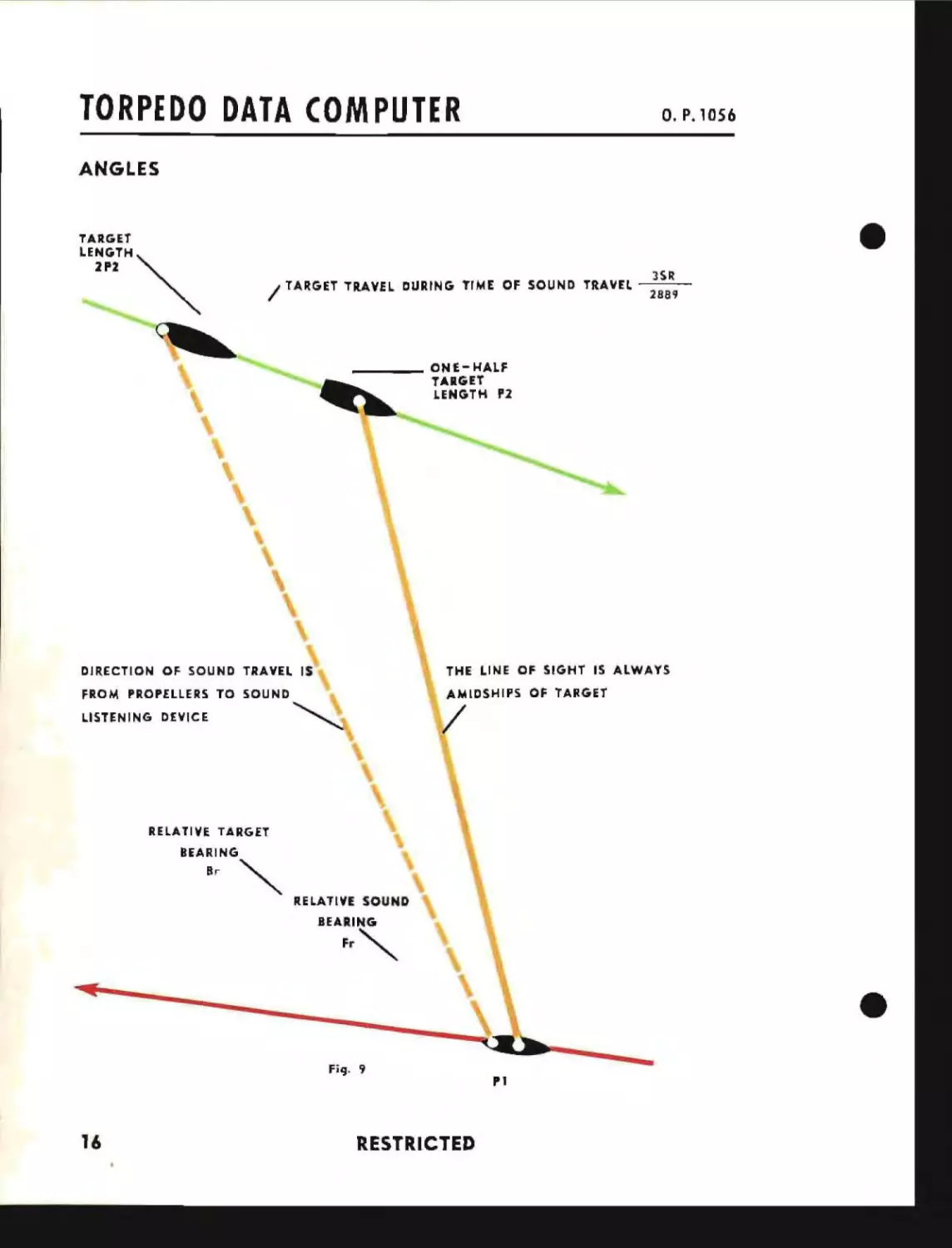
ANGLES
TARGET
LENGTH""
2P.
/
'"
TARGET TRAVEL DURING TIME OF SOUND TRAVEL
3SR
2889
_ _ _ _ ONE-HALF
TARGET
LENGTH P2
DIRECTION OF SOUND TRAVEL 1$
THE LINE OF SIGHT IS ALWAYS
FROM PROPELLERS TO SOUND
AMIDSHIPS OF TARGET
~
LISTENING DEVICE
/
RELA TI VE TARGET
BEARING
Br
~
RELATIVE SOUND
Fr"
BEARING
•
Fi9. 9
PI
16
RESTRICTED
•
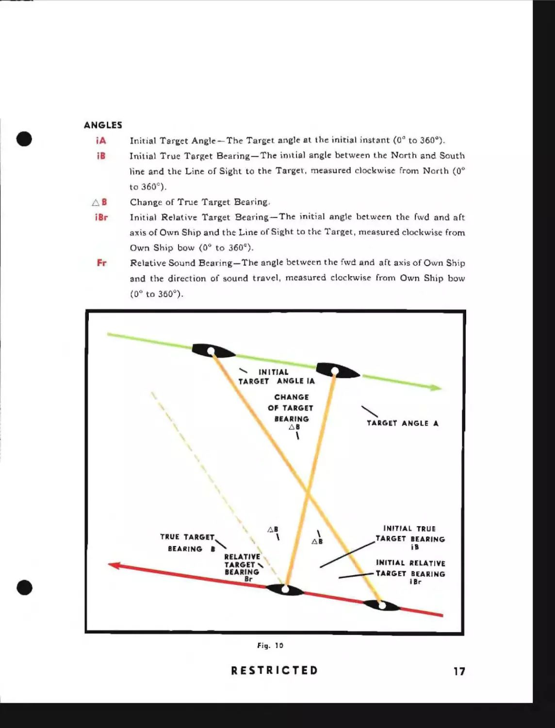
ANGLES
iA
Initial Target Angle- The Target angle at the initial instant (0° to 360 0 ).
is
Initial True Target Bearing-The inItial angle between the North and South
line and the Line of Sight to the Target, measured clockwise from North (0 0
to 360 C ) .
6 B
iBt
Change of True Target Bearing,
Initial Relative Target Bearing-The initial angle between the fwd and aft
axis of Own Ship and the Line of Sight to the Target, measured clockwise from
Own Ship bow (0 0 to 360 C ) .
Fr
Relative Sound Bearing-The angle between the fwd and aft axis of Own Ship
and the direction of sound travel, measured clockwise from Own Ship bow
(00 to 360°).
........ INITIAL
~
TARGET ANGLE IA
-
.....__-..
___
CHANGE
OF TARGET
""
BEARING
TARGET ANGLE A
1',8
\
TRUE TARGET
BEARING
\
a~ELATIYE'
;;,.8
\
INITIAL TRU E
~TARGET ~:ARING
6\
TARGET" •
BEARING
8r
~
_
~ELATIYE
INITIAL
_TARGET BEARING
Ilr
Fig. 10
RESTRICTED
17
TORPEDO DATA COMPUTER
O. P. 10S6
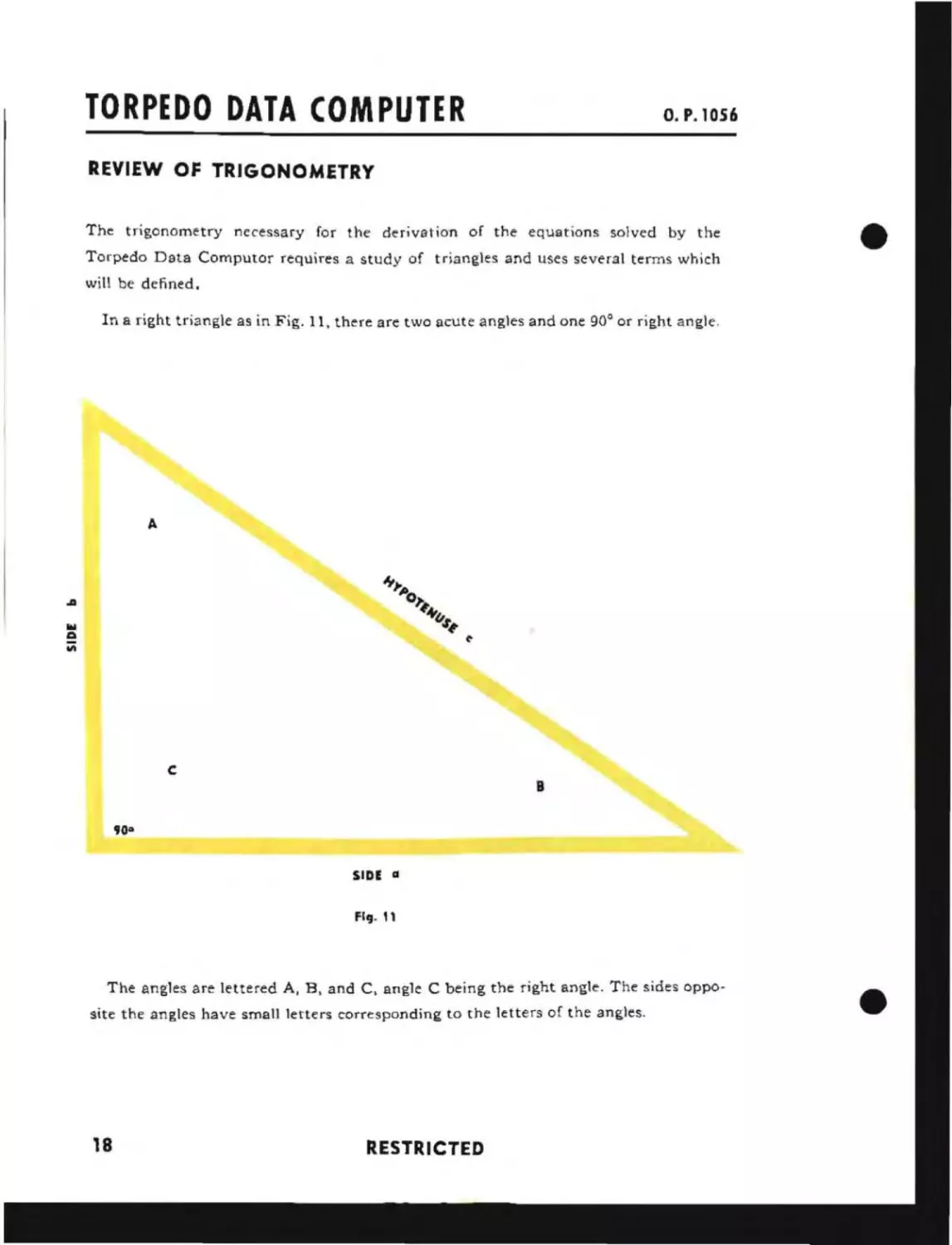
REVIEW OF TRIGONOMETRY
The trigonometry necessary for the derivation of the equations solved by the
Torpedo Data Computor requires a study of triangles and uses several terms which
will be defined.
In a right triangle as in Fig. 11, there are two acute angles and one 90° or right angle.
A
.a
c
B
900
SIDE a
Fig. "
The angles are lettered A, B, and C, angle C being the right angle. The sides opposite the angles have small letters corresponding to the letters of the angles.
18
RESTRICTED
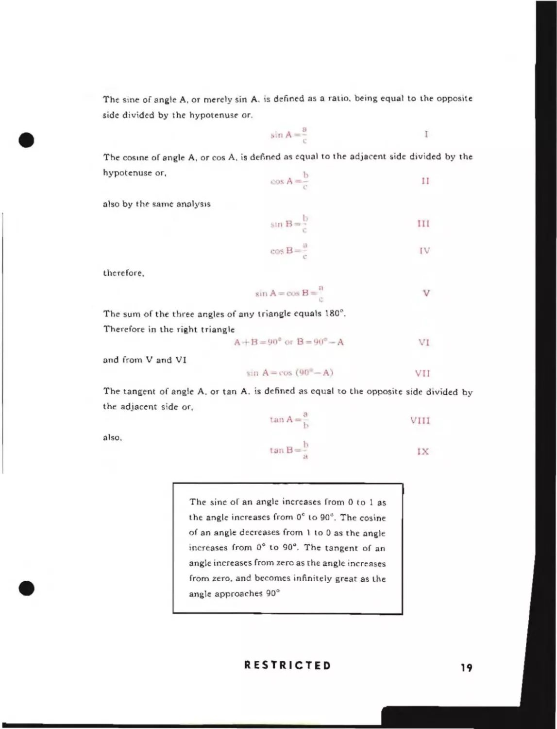
The sine of angle A, or merely sin A. is defined as a ratio. being equal to the opposite
side divided by the hypotenuse or.
~,in A=~
e
The cosme of angle A, or cos A. is defined as equal to the adjacent side divided by the
hypotenuse or,
1
<'()S
A - -('
II
also by the same analysIs
h
III
',In B=:
en", B~
.,
a
IV
c
therefore,
:IIIA=c(), B-
H
L
V
The sum of the three angles of any triangle equals 180".
Therefore in the right triangle
A
R = YOe or B = 9(1° - A
VI
and from V and VI
"Ill A-co
(9U -A
VII
The tangent of angle A. or tan A. is defined as equal to the opposite side divided by
the adjacent side or,
Ian
. A=3t
also.
l!.1I1
B=
b
<l
VIII
IX
The sine of an angle increases from 0 to 1 as
the angle increases from Dc to 90 0 . The cosine
of an angle decreases from 1 to 0 as the angle
0
increases from 0 to 90". The tangent of an
•
angle increases from zero as the angle increases
from zero, and becomes infinitely great as the
angle approaches 90 0
RESTRICTED
19
TORPEDO DATA COMPUTER
o. P. 1056
GENERAL PROBLEM
J
R~
5
~u.
Br
"
50
1
%
Co
Fig. 12
RESTRICTED
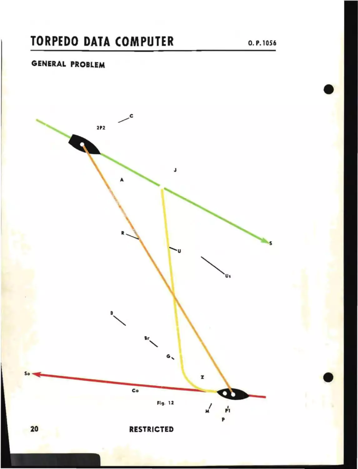
GENERAL PROBLEM
The general problem solved by the Torpedo Data Computer is
illustrated in Fig. 12. The principal parts of the Torpedo Data
Computer are: the Position Keeper, the Sound Bearing Converter, and the fwd and aft Angle Solvers.
The Position Keeper receives values of Own Speed, So, Own
Course, Co, Target Speed, S, Target Course. C, True Target
Bearing, B, and Range, R. In conjunction with a Time Motor, the
instrument will contInue to produce values indicating the position of the Target by generating values of Relative Target Bearing and Range as Own Ship and Target move. Target Angle is
also generated for use by the Angle Solver and the Sound Bearing Converter.
The Sound Bearing Converter is associated with the Position
Keeper and receives a value of Target travel during time of
sound travel, plus one-half Target length, as well as continuously
maintained values of Target Angle, Relative Target Bearing and
Range. A value of Br-Fr is continuously generated. This is
converted to Relative Sound Bearing and is continuously indicated on the dials of the Position Keeper.
The Angle Solver receives a value of Target Speed as well as
continuously maintained values of Relative Target Bearing,
Target Angle and Range from the Position Keeper. Values
pertaining to the characteristics of the particular torpedo being
used are introduced into the instrument manually. The Angle
Solver then produces a value of Gyro Angle and continues to
maintain the correct value of Gyro Angle so that a torpedo
fired from a submarine wi!! reach a point on the track of the
Target at the same time the Target reaches that point.
On the following pages are derived the equations solved by
the Position Keeper and the Angle Solver and also the equations
solved by the associated Sound Bearing Converter,
RESTRICTED
21
TORPEDO DATA COMPUTER
O. P. 1056
DERIVATION OF EQUATIONS SOLVED BY THE POSITION KEEPER
In considering the motion of a ship, the concept of infinitesimal time must be used.
An infinitesimal period of time is defined as an amount of time smaller than any assignable value. It is the duration of an instant.
If a ship accelerates while traveling on a straight course, that is, changes speed, at
each instant it will have a definite a:;signable speed. For instance, if a ship accelerated
uniformly from a speed of 10 knots to a speed of 20 knots in a period of 2 minutes, at
the end of the first minute its speed at that instant would be 15 knots.
The distance that the ship will travel during any given instant will be the product
22
RESTRICTED
•
of the speed of the ship at that instant multiplied by the duration of that instant and
IS
written So dT where dT denotes an infinitesimal period of lIme.
If all these in')tantaneous distances are added together, the result will be the total
distance traveled by the ship during the finite period of time under consideration. If the
ship were traveling at a constant speed the total distance traveled would be the speed
multiplied by the total time. However, if the speed of the ship varies during this time,
the total distance traveled during a finite period of time can only be written as the
summation of all the instantaneous products of the instantaneous speeds multiplied by
the duration of the instants that they existed, or fSo dT, where the elongated S-shaped
character indicates that the summation of the instantaneous products is to be performed.If a Target were stationary and Own Ship were traveling along the line of sight,
the instantaneous distances traveled would be the instantaneous changes in Range
dR = So d T and over a given period of time, the total change in Range would be
6 R = fSo dT where the symbol 6 denotes the total change.
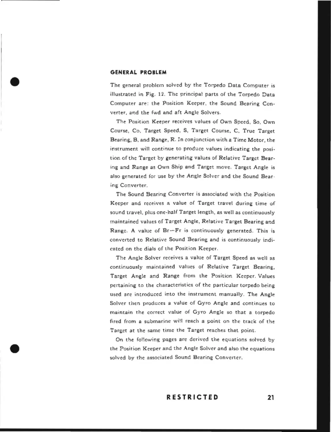
Fig. 13, illustrates a situation where the Target is stationary and at the center
of a circular course that is bemg traversed by Own Ship. The instantaneous
travel of Own Ship will again be SodT. Here, due to the instantaneous motion of Own
Ship, there will also be an instantaneous change in True Target Bearing denoted by
dB. From the
exagg~rated
figure it can be seen that R tan dB = So dT
The tangent of a very small angle is very nearly equal numerically to the angle itself
when the angle is measured in radians. For an infinitesimal angle, the tangent is exactly
equal numerically to the angle itself. Therefore, instantaneously R dB = So dT
As the ship moves in the circular path, It is constantly moving across the Line of
Sight and never along the Line of Sight. Hence there is no change in Range. The total
change in True Target Bearing is 6B = l/RfSo dT
This expression is only true when the ship is traveling in the circular path. If for
instance, Own Ship traveled along the straight path indicated by the dotted line, in
Fig. 13, the change in True Target Bearing would depend only upon the component of the motion of Own Ship across the Line of Sight, and further it must be
agreed that for each instantaneous change in True Target Bearing, the value of Range
shaH be used which corresponds to that IOstantaneous True Target Bearing.
•
The imtantaneous change in Range, dR, in this case would only be dependent upon
that component of the motion of Own Ship which is along the Line of Sight.
RESTRICTED
23
TORPEDO DATA COMPUTER
O. P. 1056
c
~ S dl
-IS
IA
I J:,Rlt
'IA
S
,
Air
,
Ll.8
So
ilril-
B-
J50 dt
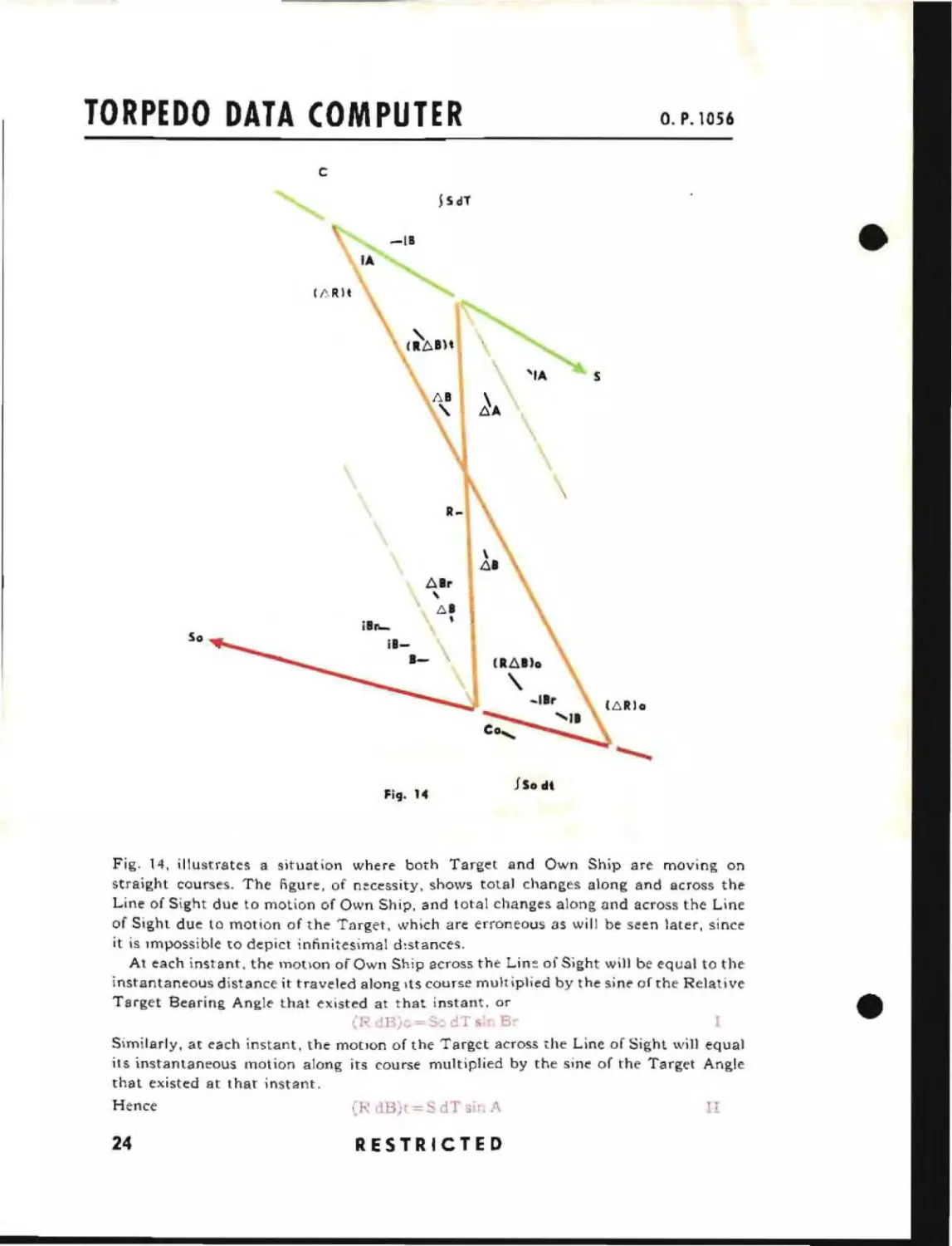
Fig. 14, illustrates a situation where both Target and Own Ship are moving on
straight courses. The figure, of n~cessity. shows total changes along and across the
Line of Sight due to motion of Own Ship, and total changes along and across the Line
of Sight due to motion of the Target, which are erroneous as will be seen later, since
it is Impossible to depict infinitesimal d~stances.
At each instant, the motlon of Own Ship across the Lin~ of Sight will be equal to the
instantaneous distance it traveled along Its course multiplied by the sine of the Relative
Target Bearing Angle that existed at that instant. or
(, dB)o=S:,dTs'r B,Similarly, at each instant, the motJOn of the Target across the Line of Sight will equal
its instantaneous motion along its course multiplied by the sine of the Target Angle
that existed at that instant.
Hence
iY dB);
24
RESTRICTED
=, dT
:;i1
/\
•
The total instantaneous change across the Line of Sight will be the sum of the change
due to Own Ship and the change due to Target motion.
Therefore.
RdB=(RdB)o-+(R
B)t=SodT ·nB -!-SdTsmA
III
Over a finite period of time
rs
R. \ B =
dT ';111 B _. IS dT sin A
IV
The instantaneous change along the Line of Sight due to the motion of Own Ship
will be the instantaneous motion of the ship along its course multiplied by the cosine
of the Relative Target Bearing Angle that existed at that instant.
dR)o=S< <.!TcosBr
V
Similarly the instantaneous change along the Line of Sight due to Target motion
will be the instantaneous motion of the Target along its course multiplied by the
cosine of the Target Angle that existed at that instant.
(dR)l-S dT co,; A
VI
Hence, the total instantaneous change along the Line of Sight, that
IS,
the total
instantaneous change in Range. is
dR = (dR)
or over a nnite period
,+ (dR)l -
So dT
cOs
Br
-j-
S dT
l'OS
A
VII
[.R = IS dT cos Br~ Is dT co~ A
VlIl
The instantaneous change in True Target Bearing may be obtained from equation III.
This equation may be rewritten
dB
=
/R(So dT
Sill
Br
S dT sin A)
IX
or over a finite period
,~B = I/R (ISo dT :in Br+ Is dT slT1 A)
X
The ratio indicated by the right hand side of this equation is actually the tangent of
the instantaneous chunge in True Target Bearing. Again, however, since dB is the instantaneous change in True Target Bearing, the tangent of the angle is numerically
equal to the angle itself if the angle is measured in radians. This is only true for the instantaneous values of dB, and the instantaneously existing value of R must be used.
From Fig. 14 the initial Range minus the sum of the changes in Range
indicated does not equal the final Range indicated. as may be found by scaling the
figure. This is due to the fact that the total change in Range. L':o.R, is the sum of instantaneous products wherein each successive product involved a trigonometric
value less than the preceding one, Hence the total change in Range is less than it
would have been if the trigonometric values of the initial angles had been used
in each instantaneous product as is erroneously depicted in the figure. The total change
across the Line of Sight is similarly erroneously indicated.
The other equations solved by the Position Keeper are illustrated in Fig. 14.
:Br=IB-Co and:A -IB-;- 80 -c
'These equ31l0n.' are tru(' only if it is :>greed that each value of R that is used with each instAntaneous
product corrt"sponds to th .. pari iculnr <.18 tit thaI il\~taflt.
RESTRICTED
25
TORPEDO DATA COMPUIER
O. P. 1056
SOUND BEARING PROBLEM
x
y
z
A
P2
/
NOTE: THIS FIGURE 15
EXAGGERATED. FOR NORMAL
RANGES 2!!..IS LESS THAN P2
US9
2P2/
R
fr
'-
PERISCOPE
SOUND LISTENING DEVICE
Flq. 1S
26
I
PI
RESTRICTED
or at any subsequent time
Sr=R
XI
Co
A = B r J 80 - C
and
X II
Equations I through IX are continuously solved by the Position Keeper, and the instantaneous products are continuously added together producing the total changes.
Further. the Position Keeper continuously adheres to the condition necessary for the
validity of Equation IX.
DERIVATION OF EQUATIONS SOLVED BY THE! SOUND
BEARING CONVERTER
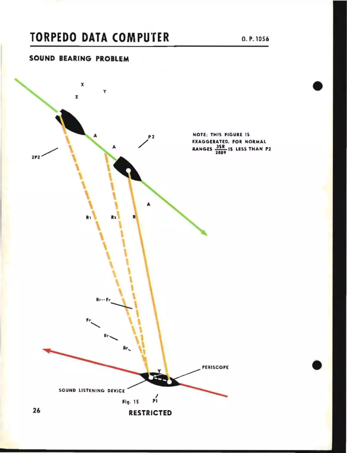
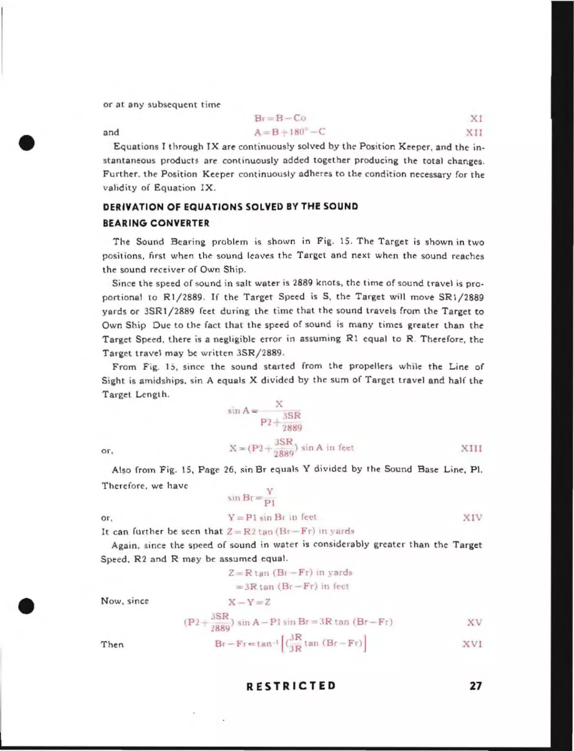
The Sound Bearing problem is shown in Fig. 15. The Target is shown in two
positions, first when the sound lenves the Target and next when the sound reaches
the sound receiver of Own Ship.
Since the speed of sound in salt water is 2889 knots. the time of sound travel is proportional to Rl/2889. If the Target Speed is S. the Target will move SR1/2889
yards or 3SRI/2889 feet during the time that the sound travels from the Target to
Own Ship Due to the fact that the speed of sound is many times greater than the
Target Speed, there is a negligible error in assuming R1 equal to R. Therefore, the
Target travel may be written 3SR/2889.
From Flg. 1 S. since the sound started from the propellers while the Line of
Sight is amidships. sin A equals X divided by the sum of Target travel and half the
Target Length.
X
sin A =
3SR
P2 ;- 21)89
JSR)
. A
X - (P 1-·- 28R9 ~\n
or,
.
In
XIII
ted
Also from Fig. 15. Page 26. sin Br equals Y divided by the Sound Base Line. PI.
Therefore. we have
y
.SIll 5r = PI
Y - PI sin Hr
or,
feet
III
XIV
It can further be seen that Z = R2 an (Br - Fr) in yards
Again. since the speed of sound in water is considerably greater than the Target
Speed. R2 and R may be assumed equal.
Z=R tan (Br-Fr) in yard-3R tan (Br-Fr) in feel
X-y-Z
Now. since
(P2
Then
JSR.
)slnA- P
'Ill
2889
8r- Fr=tsn
1
B
'R
r=:)
[(~:
an (Sr
RESTRICTED
Wl( B
Fr)]
-Fr )
xv
XVI
27
TORPEDO DATA COMPUTER
O. P. 1056
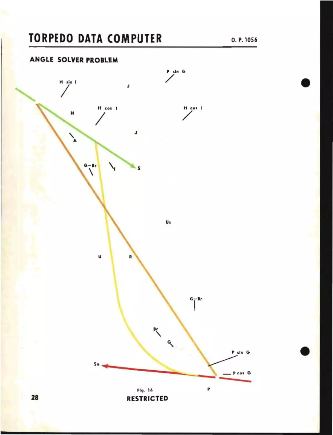
ANGLE SOLVER PROBLEM
P sin G
H sin I
/
H
H
/
J
COl
I
/
J
"
u
S
R
G-Br
I
II'
'\
P sIn G
~
50 ......
- --=-----_
FIg. 16
28
RESTRICTED
p
P
CDS
G
DERIVATION OF EQUATIONS SOLVED BY THE ANGLE SOLVER
Fig. 16 shows (he lorpedo fire. control problem b:l~t:d
of R. Sr. S, and A. From thIs ~igure
Upl)11
t
he given valu s
following equal iom Cl'lll bl': derived:
tlJ(;
XVII
Reo (G-Br)-Hc -I=U-+Pco G
Rsin (G-Br)-H -inl-J+P -inC
XVIII
XIX
I=A+(G-Br)
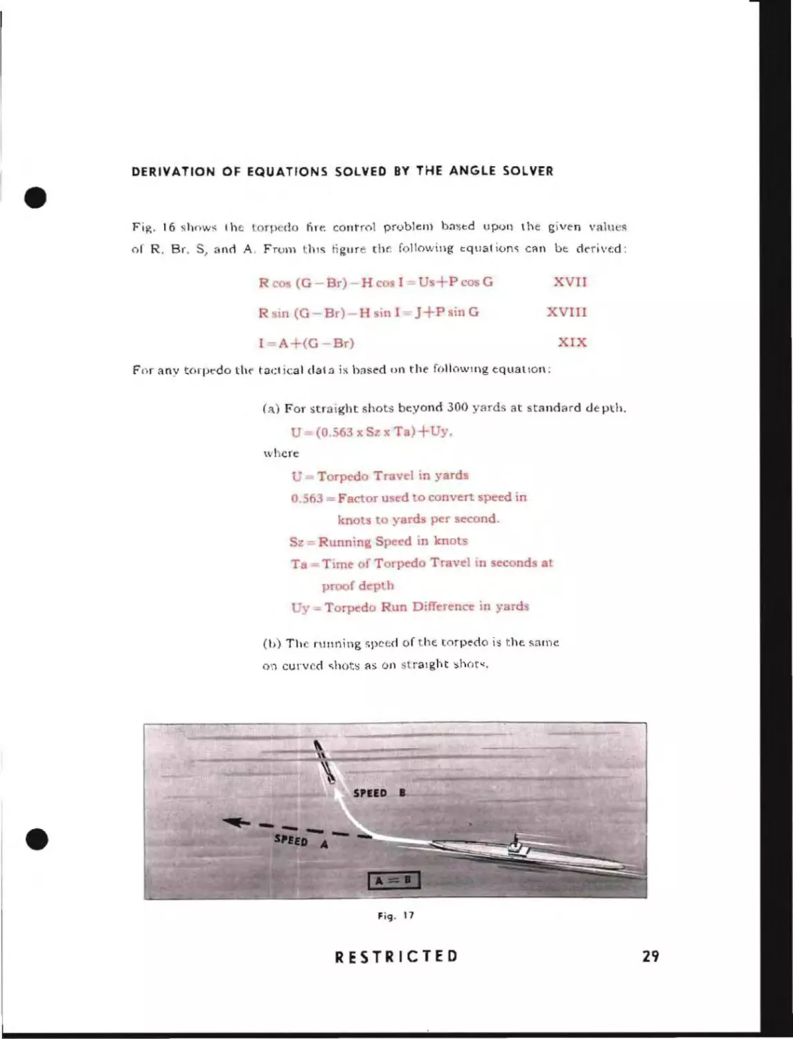
Foranv torpedo tlH' tactical dala is based on the following equatIon:
(a) For straight shob beyond 300 yards at standard depth.
- (0.563 x Sz x Ta) +Uy.
where
= Torpedo Travel
in yards
0.563:=; Factor used to convert speed in
kno
0
yards p r second.
Sz = Running Sp cd in knots
Ta = Time of Torp do Travel in second a
proof depth
'v=Torp do Run Differenc in yards
(Il) The running spc(;d of the torpedo is the. same
0',)
curved <;hots as on :;;tr3lght shor~.
F'9' 17
RESTRICTED
29
TORPEDO DATA COMPUTER
o. P. 1056
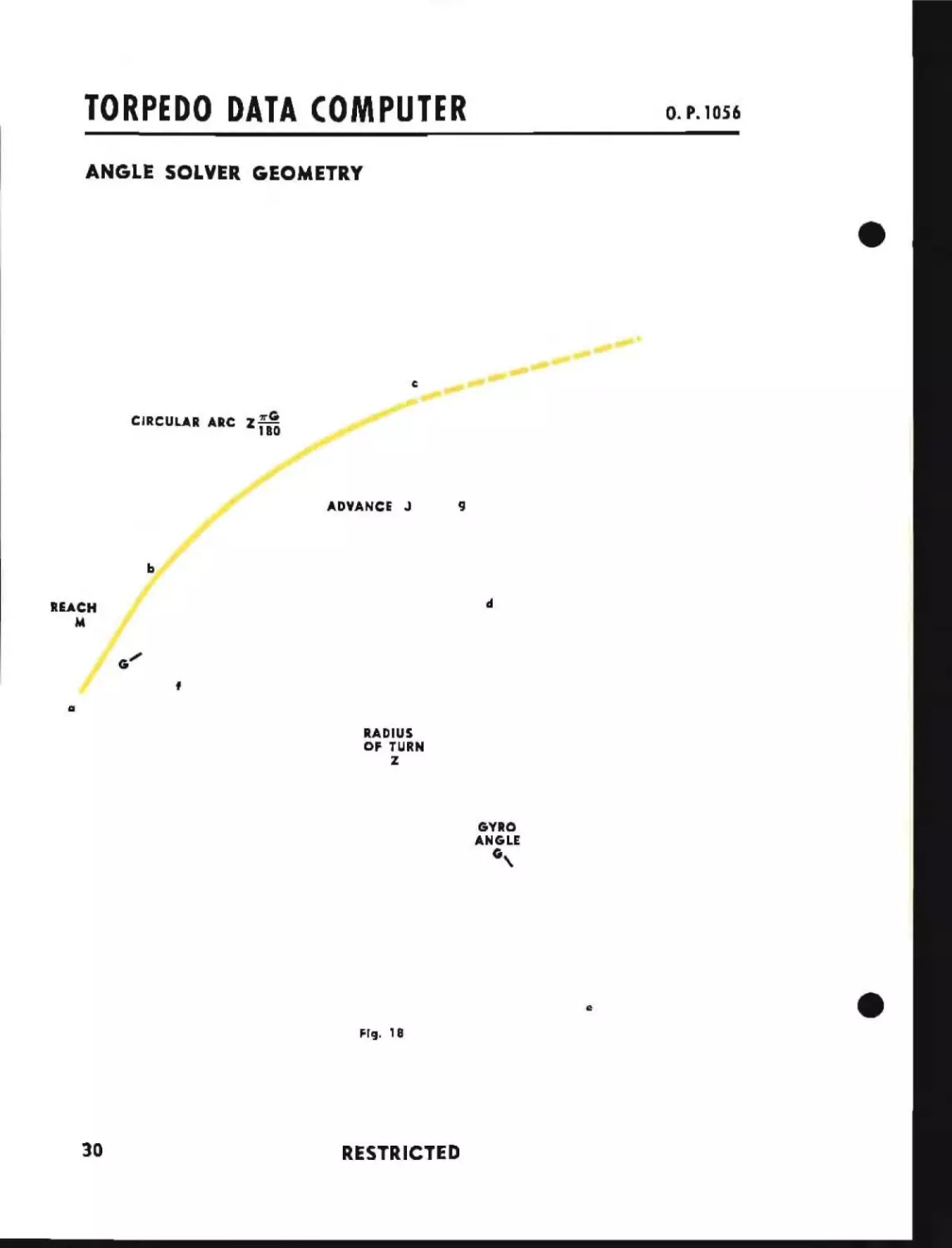
ANGLE SOLVER GEOMETRY
CIRCULAR ARC Z
~~
ADVANCi
J
9
d
REACH
M
f
a
RADIUS
OF TURN
Z
GYRO
ANGLE
G,
e
FIg. , 8
30
RESTRICTED
•
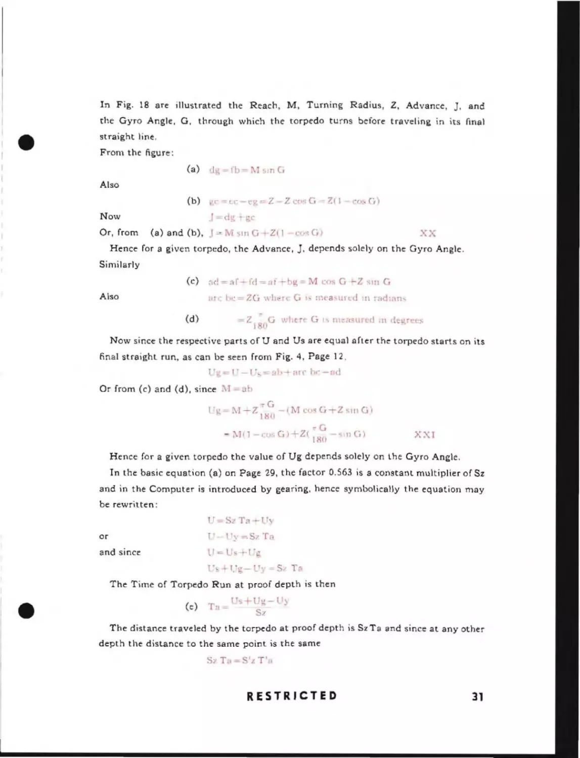
In Fig. 18 are illustrated the Reach, M, Turning Radius, Z, Advance,
J.
and
the Gyro Angle, G, through which the torpedo turns before traveling in its flnal
st raight line.
From the figure;
(a)
ug-(b- lsmG
(b)
',c-u;-('g--Z
Also
J-
Now
Or, from
(a) and (b),
d"
J -" M
ZC(l~;G-':"(l
("osCi)
gc
'<Ill
-c,~
G +Z( I
Hence for a given torpedo, the Advance,
J,
GJ
XX
depends solely on the Gyro Angle.
Similarly
(c)
Also
(d)
=
Z - G wllue G
IS m"ClSUrt d J11 (kgr
181
•
'rs
Now since the respective parts of U and Us are equal after the torpedo starts on its
final straight run, as can be seen from Fig. 4, Page 12,
Or from (c) and (d), since NT l."g-
0. )
r-r -2 "G I
l1;llJ
(1\".
1'1
0,
C'J - Z·
5111 G')
~G
-:\J(l-c()~;G)--LZ(lR()
~lIlCr)
XXI
Hence for a given torpedo the value of Ug depends solely on lhe Gyro Angle.
In the basic equation (a) on Page 29, the factor 0.563 is a constant multiplier of Sz
and in the Computer is introduced by gearing, hence symbolically the equation may
be rewritten;
"-SzTa+l..y
l~
or
=.Sz Ts
and since
t'"....
l"oT,-S/T,
,
.
"
The Time of Torpedo Run at proof depth is then
(e)
Ta _ .Ts +Uo-lI\
b".
Sl
The distance traveled by the torpedo at proof depth is SzTa and since at any other
depth the distance to the same point is the same
RESTRICTED
31
Substituting this in (e) the Corrected Time of Torpedo Run is then
t;g- ".:
-S'i'
If the Target and torpedo are to arrive at the same point at the same time, one
T
'
il -
Us
necessary condition is that the Time of Target Run must be the same as the Corrected
Time of Torpedo Run.
Therefore
T'a
,;+Ug-U.\·
8';
H
S
XXII
If the numerical values of Us+Ug-Uy and S'z are used graphically to represent the
sides opposite and adjacent respectively to an angle of a right triangle, that angle
must be an angle whose tangent is Tla. Similarly if the numerical values of Hand S are
also the sides opposite and adjacent to an angle of a right triangle, that angle must
also be an angle whose tangent is Tis if the Target and torpedo are to meet.
The foregoing equations solve the fire
control problem. Each mathematical
process in the solution of these equations may be performed mechanically
or electro-mechanically as will be shown
in the following discussion on the fundamentals of mechanisms. The function
of the Torpedo Data Computer is to
solve the problem and. provided that
the Target follows a straight course at
constant speed. maintain a continuous
solution.
•
32
RESTRICTED
FU DA E TALS
The Data Computer consiSlS of severa
d istinCl
types of COlnpul ing
devIces which operate together to
solve the equations of the fire control
problem. These devices are for the
most part const rueted as ind Ividua \
units. In this chapter are described
the underlying principles of their
operatIon .
•
SECTION 2
RESTRICTED
33
o..
D F
The most common calculating mechanism in the Computer
can
perfo~m
15
the differential, which
addition nnd subtraction.
The bevel gear differential occurs most often and will therefore be considered first.
•
34
RESTRICTED
The bevel gear differential is illustrated in Fig. 19. Its components are the large
bevel gears, A and C. which supply the input quantities, and the set of spider gears,
B, which generate the output quantity and transmit it to shaft D. The spider gears
and their shafts are shown in Fig. 2l. The two gears B1 and 82 are free to rotate
on the shafts bland b2. which in turn are rigidly fastened to shaft D.
A
I
F1V. 22
In Fig. 22, if both driving gears A and C are moving in the same direction at the
same speed. the point
spider gear B
Will
ClI
will remain opposite point c as the gears rotate. Therefore, the
not rotate on its shaft, but will be carried along with the driving
gears causing shaft 0 to move at the same speed as the gears A and C.
Since the differential is used to add the rotations of the two input gears, it is necessary
to double the speed of the output shaft with a set of 2 to 1 gears, which will give the
correct rotation to shaft E, that is, two revolutions for one of A plus one of C.
•
When only one input gear is turning, such as A in Fig. 23, Page 36, shaft E shOUld
turn only one revolution for each rotation of A. As gear A moves, the spider gear B
rolls on the gear C and its center moves only half as far as the gear A. The shaft E is
then rotating at the same speed as A.
RESTRICTED
35
o. P. l056
-A
I
E
I TO 2
"
RATIO-< "
'"
,
a
"
Fiq.23
I
E
-A
,
Fiq.24
A
I
c:
b
a
t:
--- ---0
C
Fig. 25
36
RESTRICTED
8
Fi9. 25 a
J
•
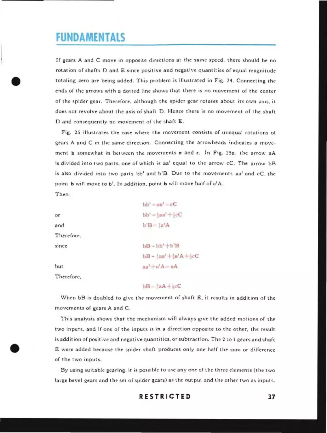
If gears A and C move in opposite directions at the same speed, there should be no
rotation of shafts D and E since posit lve and negative quantities of equal magnitude
totaling zero are being added, This problem is illustrated in Fig, 24, Connecting the
ends of the arrows with a dotted line shows that there is no movement of the center
of the spider gear. Therefore, although the spider gear rotates about its own aXIS, it
does not revolve about the axis of shaft D. Hence there is no movement of the shaft
D and consequently no movement of the shaft E.
Fig. 2S illustrates the case where the movement consists of unequal rotations of
gears A and ClOthe same direction. Connecting the arrowheads indicates a movement b somewhat in between the movements a and c. In Fig. 25a. the arrow aA
is divided into two parts, one of which is aa l equal to the arrow cC. The arrow bB
is also divided into two parts bb' and h'B. Due to the :,novements aa' and cC, the
point b will move to b'. In addition, point b will move half of a'A.
Then:
bh' = a
'=; cC
blJ' = _a3' +~·C
or
IB
and
'alA
Therefore.
1B -= 111 'Tb'B
since
bB - ,Iaa' +-\a'A+~cC
but
aa l
a'
bB-
'aA+.~cC
aA
Therefore,
When bB
i~
doubled to give t h .. movement of shaft E. it results in addition of the
movements of gears A and C.
This analysis shows that the mechanism will always give the added motions of tht'
two inputs, and if one of the inputs is in a direction opposite to the other, the result
is addition of posit~ve and negative quantities, or subtraction. The 2 to 1 gears and shaft
E were added because the spider shaft produces only one half the sum or difference
of the two inputs.
By using suitable gearing. it
,s possible to use any on.. of the three elements (the two
large bevel gears and t h(" sel of spider gears) as the output and the oth .. r two as inputs.
RESTRICTED
37
o
o
III
c
38
RESTRICTED
..
•
IN
•
IN
A
•
D
c
FilJ.
28A
A
.--~'
D
c
FIIJ.
2n
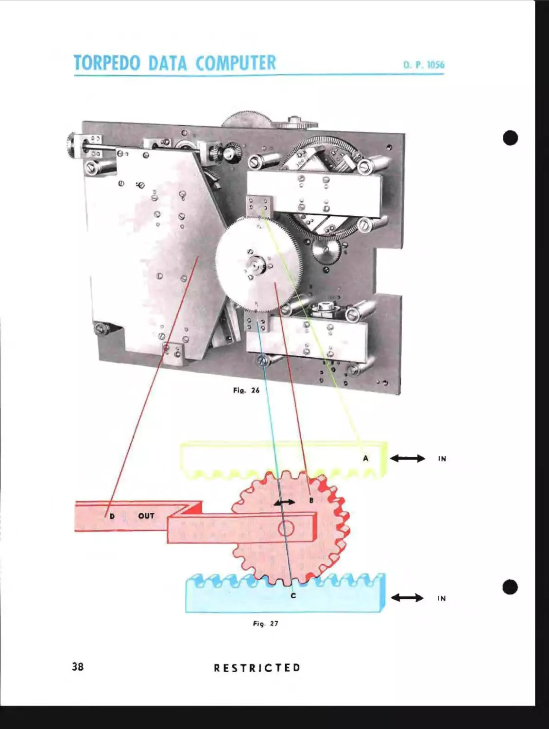
Another type of differential which is used is the rack and pinion combination shown
in Figs. 26 and 27. In this mechanism the two racks A and C deliver the
inputs and the pinion B transfers the output to the carriage D.
The same type of analysis can be made for this device as was made for the bevel
gear differential. When both racks move the same distance in the same direction, the
pinion will not roll but will be carried along with the two racks as shown in Fig. 28a.
In this case the movement of B is half of A plus half of C. The output may be doubled
•
as before.
If in Fig. 28b the rack A moves in the direction and amount shown by the arrow and
the rack C remains stationary, the pinion B will roll on the rack C and its cente.- will
move half as far as A moved. Therefore, the carriage 0 will also move half as
ra.- as
A
moved. Further analysis of the rack and pinion differential is identical with that of the
bevel gear differential.
RESTRICTED
39
6
A
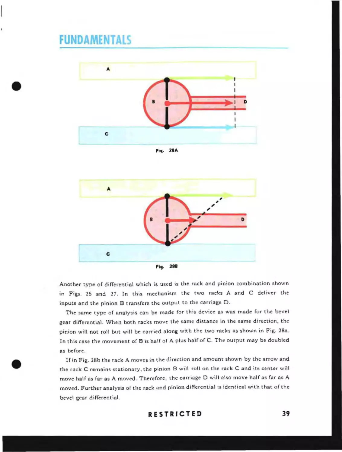
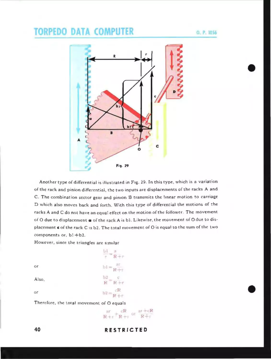
Another type of differential is illustrated in Fig. 29. In this type, which is a variation
of the rack and pinion d~fferential. the two inputs are displacements of the racks A and
C. The combination sector gear and pinIon B transmits the lmear motion to carriage
D which also moves back and forth. With this type of differential the motions of the
racks A and C do not have an equal effect on the motion of the follower. The movement
of 0 due to displacement a of the rack A is bl. Likewise, the movement of 0 due to displacelnent c of the rack C
IS
b2. The total movement of 0 is equal to the sum of the two
components or, bl +b2.
However, since the triangles are s:mllar
Lll
'"
<I
R-r
=
or
1>\
Also.
h2
R
or
1, . _ ,'R
8r
l~+r
("
R
r
R +r
Therefore, the total movement of 0 equals
cR
R
40
;.1r+cR
R
RESTRICTED
c
A
D
Fig. ]0
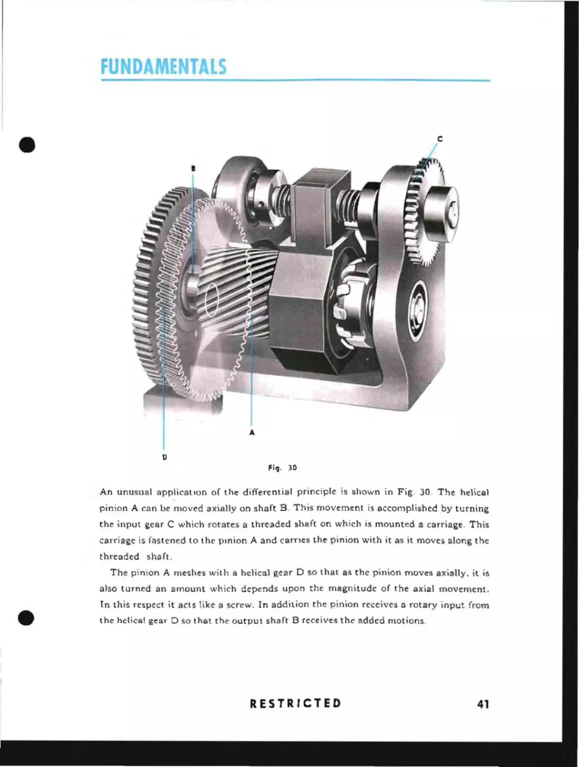
An unusual applicatIon of the differential principle is shown in Fig, 30, The helical
pinion A cnn be moved axially on shaft R This movement is accomplished by turning
the input gear C which rotates a threaded shaft on which is mounted a carriage. This
carriage is fastened to the pinion A and carnes the pinion with it as it moves along the
threaded shaft.
The pinion A meshes with a helical gear 0 so that as the pinion moves axially, it is
also turned an amount which depends upon the magnitude of the axial movement.
•
In this respect it acts like a screw. In addition the pinion receives a rotary input from
the helical gear D so that the output shaft B receives the added motions,
RESTRICTED
41
O. P. 1 b
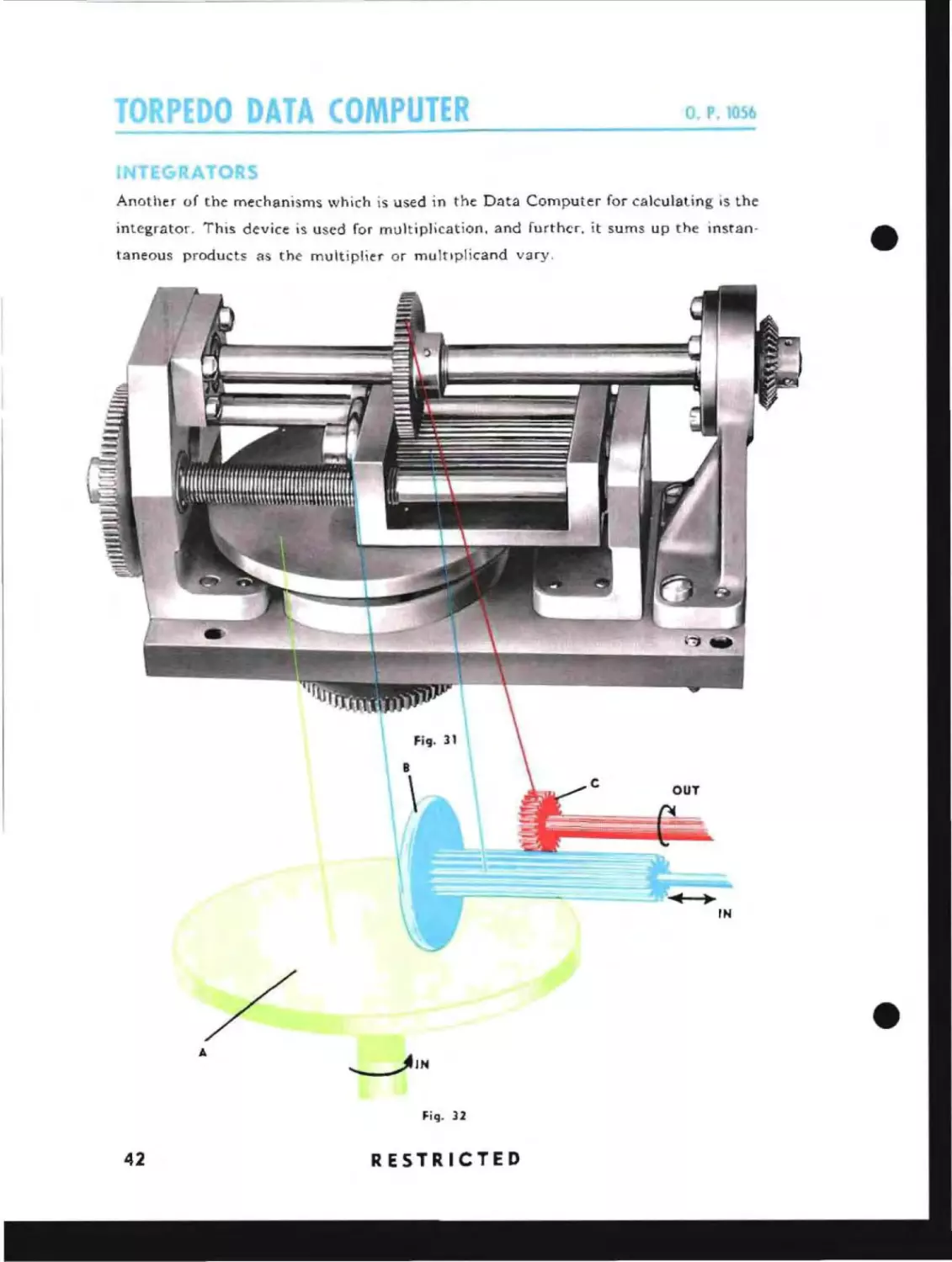
Another of the mechanisms which is used in the Data Computer for calculating is the
integrator. This device is used for multiplication, and further, it sums up the instantaneous products as the multiplier or multIplicand vary_
/
A
----JJN
Fig. 32
42
RESTRICTED
•
FU
When used in conjunction with a motor and a follow-up head, this unit may also be
used for division and will sum up the instantaneous quotients as the divisor or dividend
vary. This latter use of the integrator is explained on Page S 1.
The integrator is illustrated in Figs. 31 and 32. One of the inputs consists
of rotation of the large disc A, and the other input consists of locating the follower
roller B at various radii on the disc. As the disc revolves it causes the roller to rotate
and transmit the motion to the output pinion C. The amount of rotation of B depends
upon its distance from the center of A and upon the rotation of A. For a given disc
speed, zero rotation results when the point of contact is at the center of the disc and
maximum rotatlon results when the point of contact is at the outside edge of the disc.
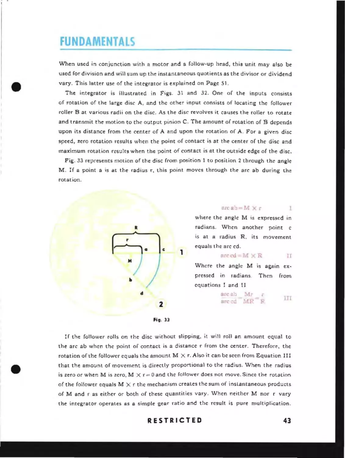
Fig. 33 represents motion of the disc from position 1 to position 2 through the angle
M. If a point a is at the radius r, this point moves through the arc ab during the
rotation.
arc a) =
1
J
1
where the angle M is expressed
radians.
R
When another
is at a radius R, its
r
a
c
c
movement
equals the arc cd.
1
~r,-
n.l
To'
Where the angle M
pressed
.b
point
In
in
radians.
equations I and II
d
2
nrc ,,::;,
arc _
Mr
'vIP
R
n
IS
again ex-
Then
.
"
I,'
from
T'I
fill- 33
If the follower rolls on the disc without slipping, it will roll an amount equal to
the arc ab when the point of contact is a distance r from the center. Therefore, the
•
rotation of the follower equals the amount M X r. Also it can be seen from Equation I II
that the amount of movement is directly proportional to the radius. When the radius
is zero or when M is zero, M X r = 0 and the follower does not move. Since the rotation
of the follower equals M X r the mechanism creates the sum of inslantaneous products
of M and r as either or both of these quantit ies vary. When neither M nor r vary
the integrator operates as a simple gear ratio and the result is pure multiplication.
RESTRICTED
43
o. P. 1056
RESOLVE
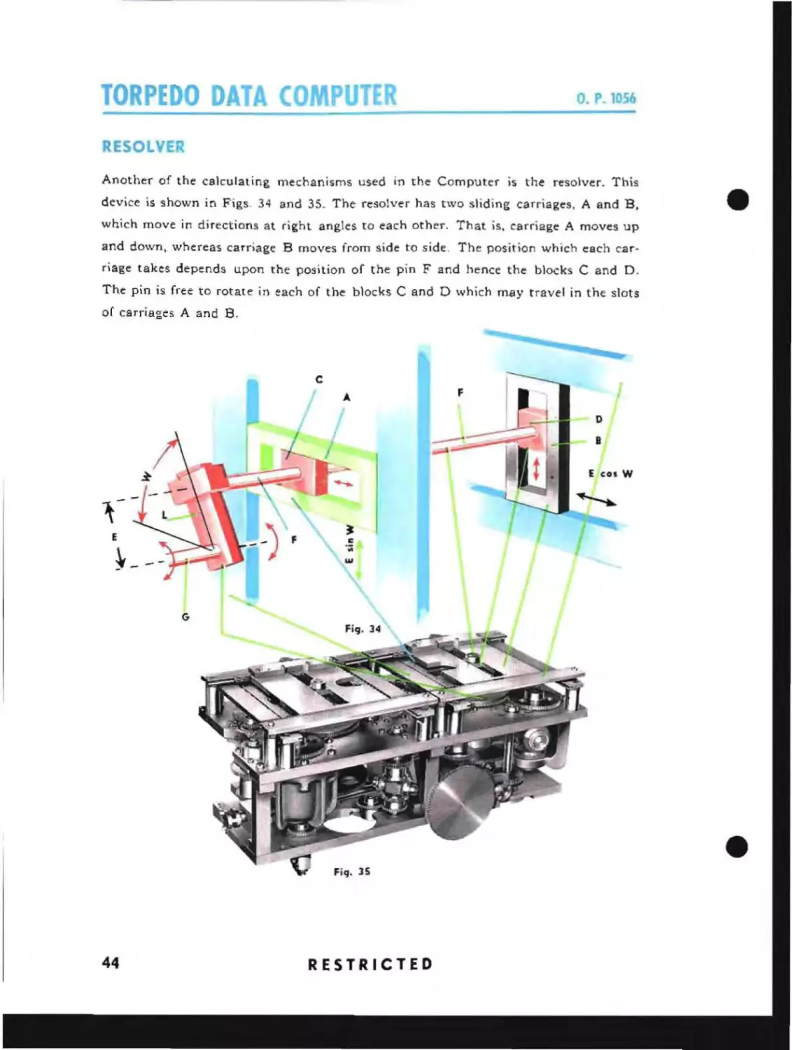
Another of the calculating mechanisms used in the Computer is the resolver. This
device is shown in Figs. 34 and 35. The resolver has two sliding carriages. A and B.
which move in directions at right angles to each other. That is. carriage A moves up
and down, whereas carriage B moves from side to side, The position which each carriage takes depends upon the position of the pin F and hence the blocks C and D.
The pin is free to rotate in each of the blocks C and D which may travel in the slots
of carriages A and B.
E
~G
44
RESTRICTED
•
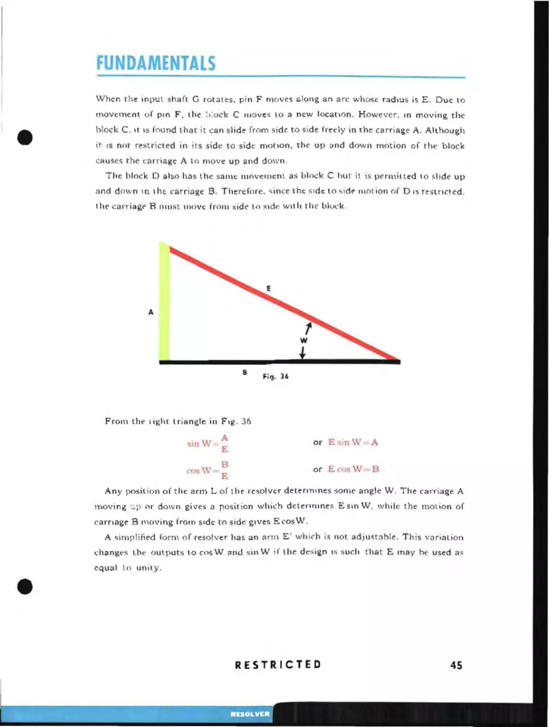
\lVhen the inPUl shaft G rotates. pin F moves along an arc whose radIUS is E. Due to
movement of pm F, the :>:uck C moves lO a new locatIon. However.
block C. It \s found that it can slide from
~ide
In
moving the
to side fretly in the carriage A. Although
it IS not restricted in its side to side motIon, the up and down motion of the block
causes the carriage A to move up and down.
The block 0 also has the s:ul1e movement as hlock C hut it is perll\illed lo slide up
and dov".. n In Iht carriage B. Therefore. ~ince the side: lo side llIotion of 0 IS reslncted.
I he
carriage R Illust move frolll side 10
slcl~ wll
II tile block.
A
B
Fig. 36
From the 1 ight I rjangle in FIg. 36
1,
sin \/
A
E
or
B
ESII1
os v.. =B
or E
rosW- E
W=A
Any position of the arm L of the resolver detenY"llnes some angle W _ The canlage A
moving '-':'P or down gives a rosition which dettnnmes E sm W, while the mOlion of
carnage B moving f rOIn Side to side gIves E cos W.
A simplified form of resolver has an
<.:hanges the" OUlputs to ,osW
<l1\(j
anll
E' whi,h
IS
sinW if the design
not adjust3ble. This vnriation
IS
such that E may he- used as
equal to unity.
RESTRICTED
45
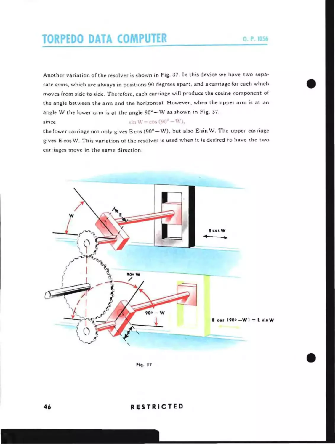
Another variation of the resolver is shown in Fig. 37. In this device we have two separate arms, which are always in positions 90 degrees apar~, and a carriage for each whIch
moves from side to side. Therefore, each carriage will produce the cosine component of
the angle between the arm and the horizontal. However, when the upper arm is at an
angle W the lower arm is at the angle 90 c -W as shown in Fig. 37.
since
-;in\-V-cO~«(O
-\\').
the lower carriage not only gives Ecos (90 -W), hut also Esin W. The upper carnage
0
gives E cos W. This variation of the resolver IS used when it is desired to have the two
carriages move in the same direction.
..
.
Ec:aiW
E cos 190"-Wl
Fi':l' 37
46
RESTRICTED
= E ,lnW
s
FUNDA
~
I
DISTANCE TO TRAC~
a
Fig. 38
I
I
D12345678
Fig. 39
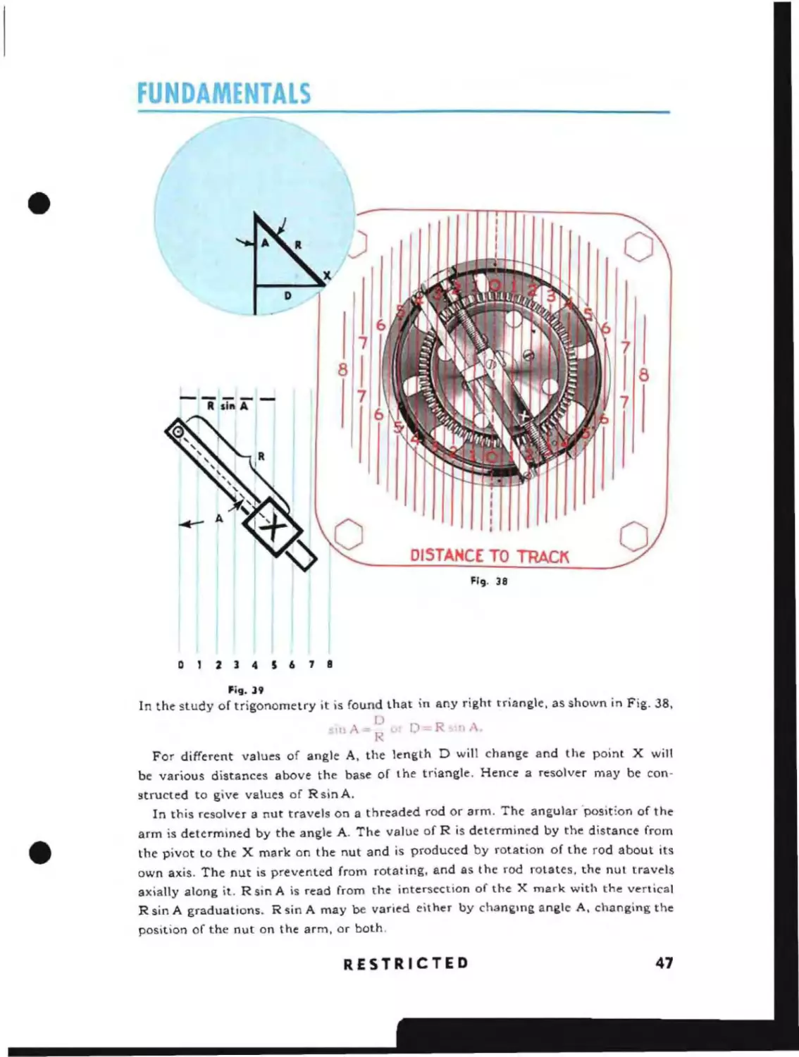
In the study of trigonometry it is found that in any right triangle, as shown in Fig. 38,
o
oIllA=R
PI
D=R~'nA
For different values of angle A, the length D will change and the point X will
be various distances above the base of the triangle. Hence a resolver may be constructed to give values of R sin A.
In this resolver a nut travels on a threaded rod or arm. The angular 'position of the
arm is determined by the angle A. The value of R is determined by the distance from
the pivot to the X mark on the nut and is produced by rotation of the rod about its
own axis. The nut is prevented from rotating, and as the rod rotates, the nut travels
axially along it. R sin A is read from the intersection of the X mark with the vertical
R sin A graduations. R sin A may be varied either by changing angle A, changing the
position of the nut on the arm, or both.
RESTRICTED
47
TORPEDO DATA COMPUTE
o.
P. 1056
PROPORTIONATOR
D
o-
-----...~~_.IJtr''t!
~-I--
B
C
.....- . . . ; - - - - - - A .
~-----G
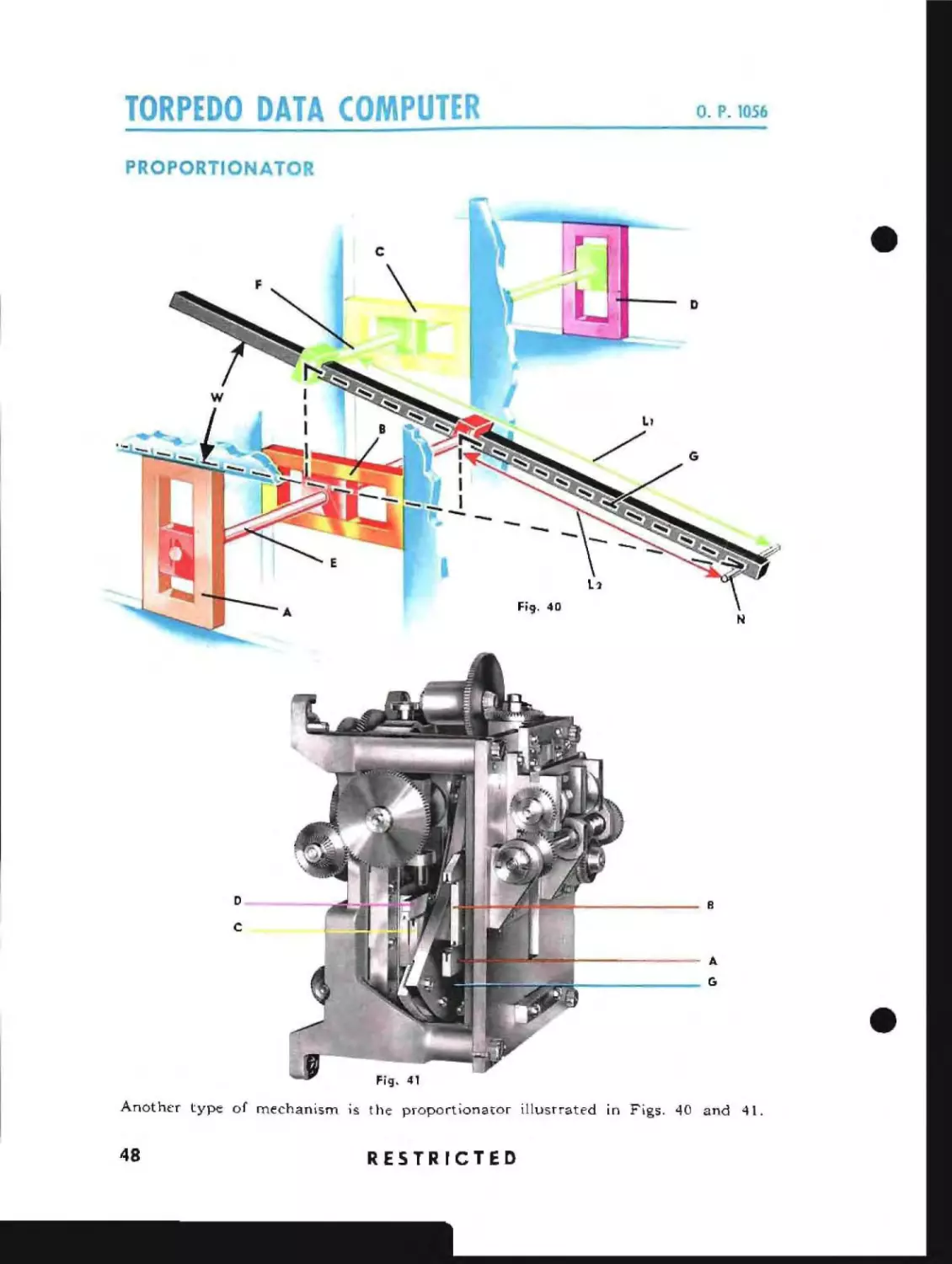
Another type of mechanism is the proport ionator illustrated in FlgS. 40 and 41.
48
RESTRICTED
•
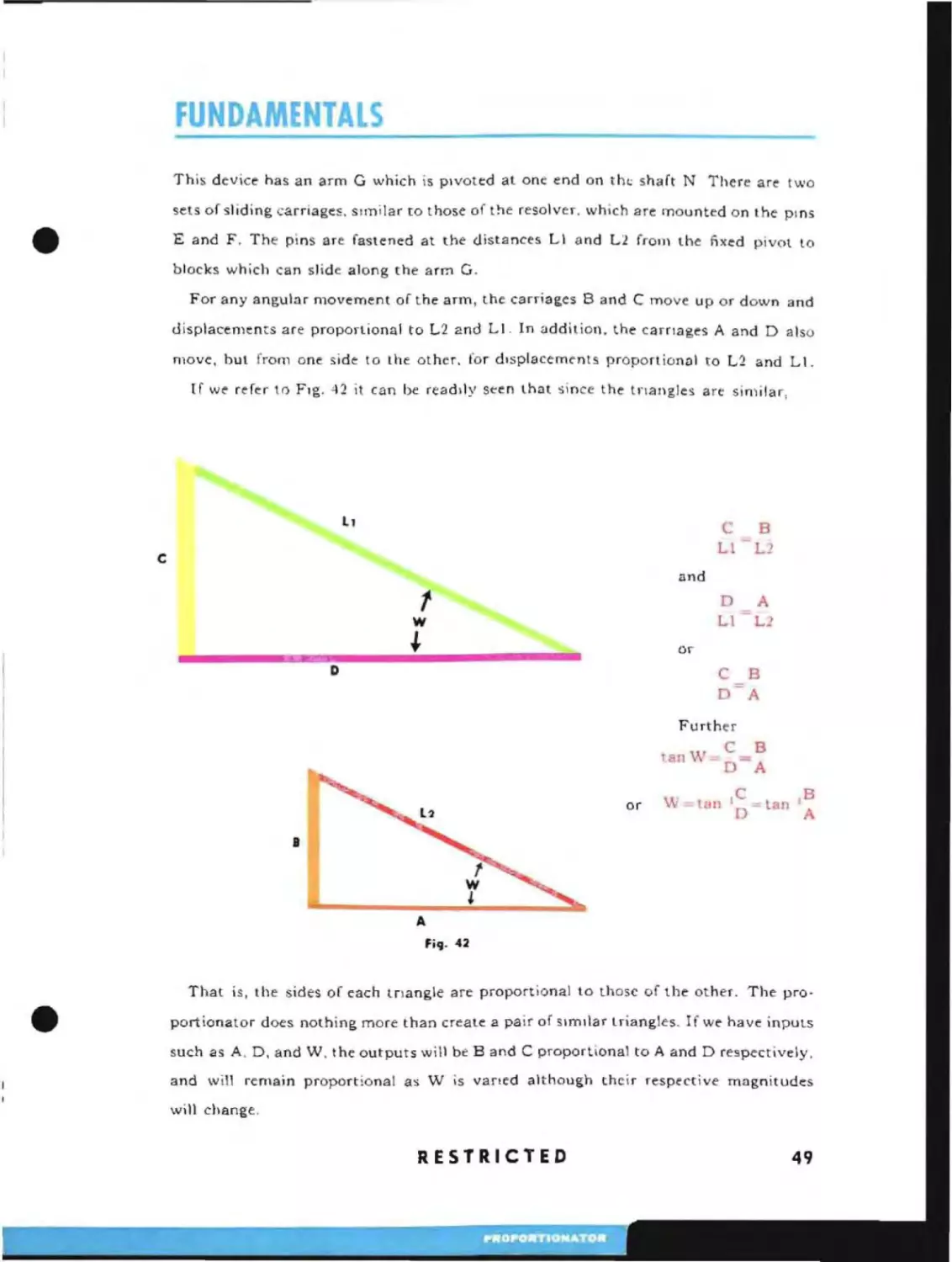
This device has an arm G which is pIvoted at one end on thl shaft N There are two
sets of sl iding carriages. sunilar to those of the resolver. which are ITIounted on t he pinS
E and F. The pins are fastened at the distances LI and L2 frOJ)) the fixed pivot to
blocks which can slide along the arm G.
For any angular movement of the arm, the carriages Band C move up or down and
displacements are proportional to L2 and LI. In addition. the carnages A and D also
move. bUl from one side to the other. for dIsplacements proportionnl to L2 and LI.
If we refer to FIg. 42 it can be rcaddy seen that since the tnangles are similar,
Ll
C
Ll
C
B
L2
and
t
W
~
D
A
LI
L_
or
D
C
D
B
A
Further
tan
or
W
WeB
-0- A
tan
I
C
D
=:
tan
I
B
A
I
A
Fiq. 42
That is, the sides of each tnangle are proportional to those of the other. The pro·
portionator does nothing more than create a pair of SImilar triangles. If we have inputs
such as A, D. and W. the outputs will be Band C proportional to A and D re9pectively,
and will remain proportional as W is vaned although their respective magnitudes
will change.
RESTRICTED
49
o.
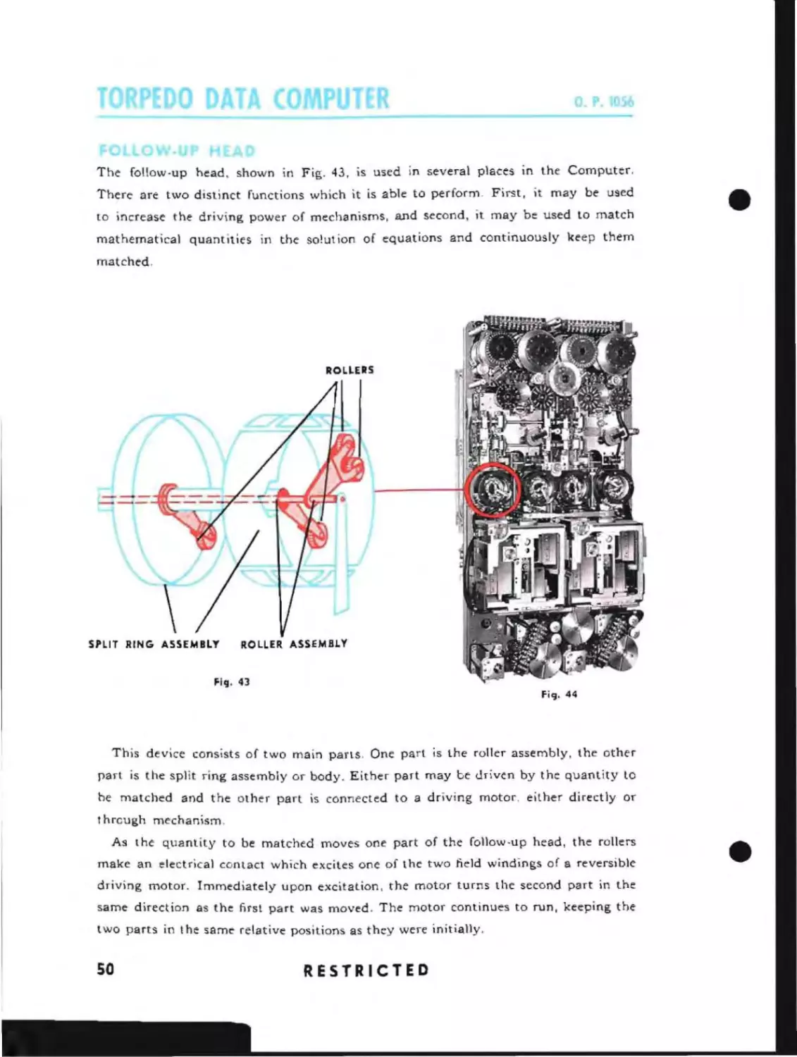
The follow-up head, shown in Fig. 43, is used in several places in the Computer.
There are two distinct functions which it is able to perform. First, it may be used
increase the driving power of mechanisms, and second. it may be used to match
to
mathematical quantities in the solution of equations and continuously keep them
•
matched.
ROLLERS
\
SPLIT RING ASSEMBLY
ROLLER ASSEMBLY
Fi':l. 43
fi9·44
This device consists of two main parts. One part is the ralter assembly, the other
part is the split ring assembly or body. Either part may be driven by the quantity to
he matched and the other part is connected to a driving motor. either directly or
I
hrcugh mechanism.
As the quantity to be matched moves one part of the follow.up head, the rolters
make an electrical contact which excites one of the two field windings of a reversible
driving motor. Immediately upon excitation, the motor turns the second part in the
same direction as the first part was moved. The motor continues to run, keeping the
two parts in the same relative positions as they were initially.
so
RESTRICTED
•
FUNDAMENTALS
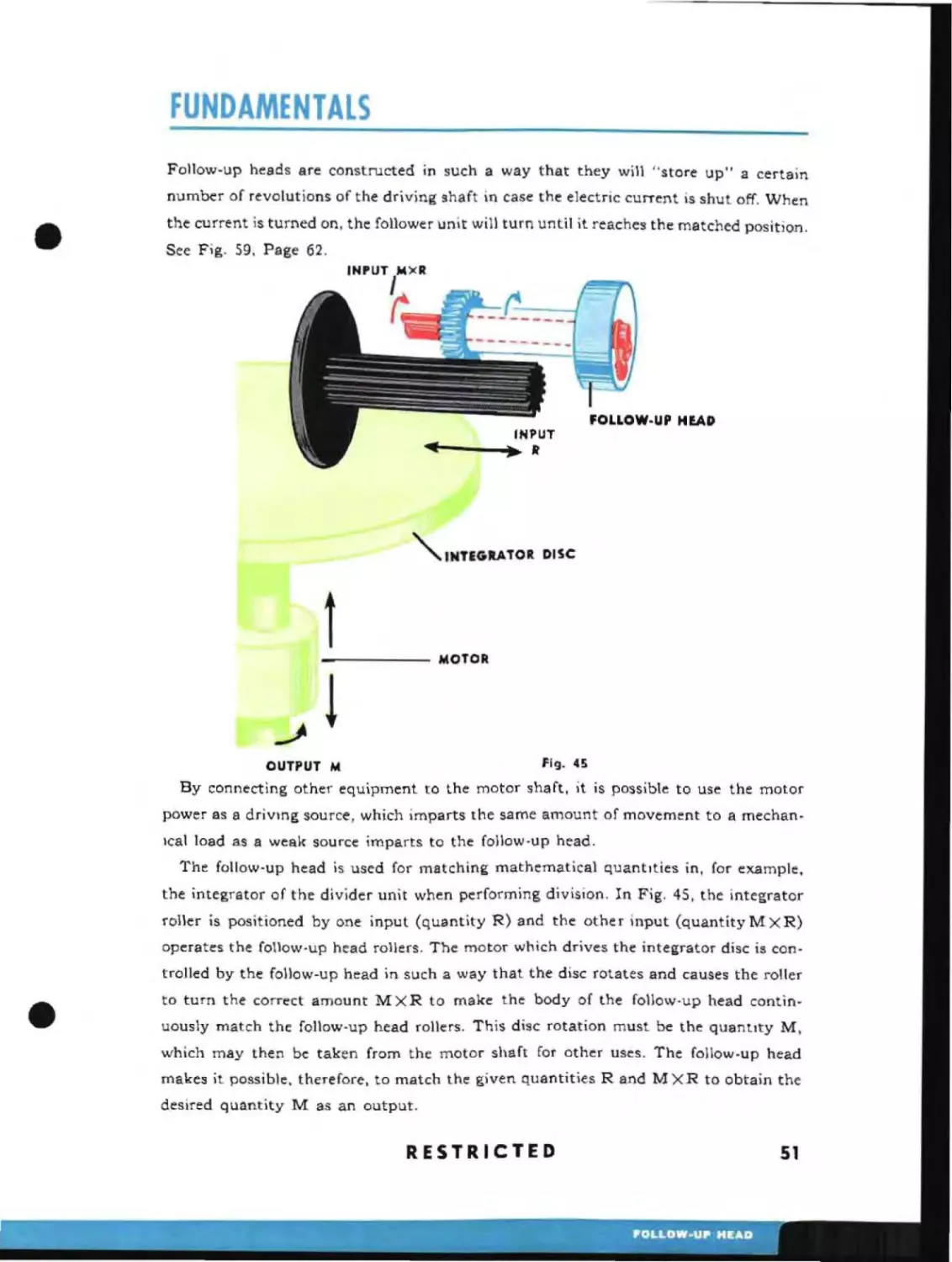
Follow-up heads are constructed in such a way that they will "store up" a certain
number of revolutions of the driving shaft in case the electric current is shut off. When
the current is turned on, the follower unit will turn until it reaches the matched position.
See Fig. 59, Page 62.
""...INTEGRATOR DISC
t
!
MOTOR
OUTPUT lit
fig_ 45
By connecting other equipment to the motor shaft, it is possible to use the motor
power as a driVing source, which imparts the same amount of movement to a mechanIcal load as a weak source imparts to the follow-up head.
The follow-up head is used for matching mathematical quantIties in, for example.
the integrator of the divider unit when performing division. In Fig. 45, the integrator
roller is positioned by one input (quantity R) and the other input (quantityMXR)
operates the follow-up head rollers. The motor which drives the integrator disc is controlled by the follow-up head in such a way that the disc rotates and causes the roller
to turn the correct amount M X R to make the body of the follow·up head continuously match the follow-up head rollers. This disc rotation must be the quantity M,
which may then be taken from the motor shaft for other uses. The follow-up head
makes it possible. therefore, to match the given quantities Rand MXR to obtain the
desired quantity M as an output.
RESTRICTED
51
O. . 1056
CAM
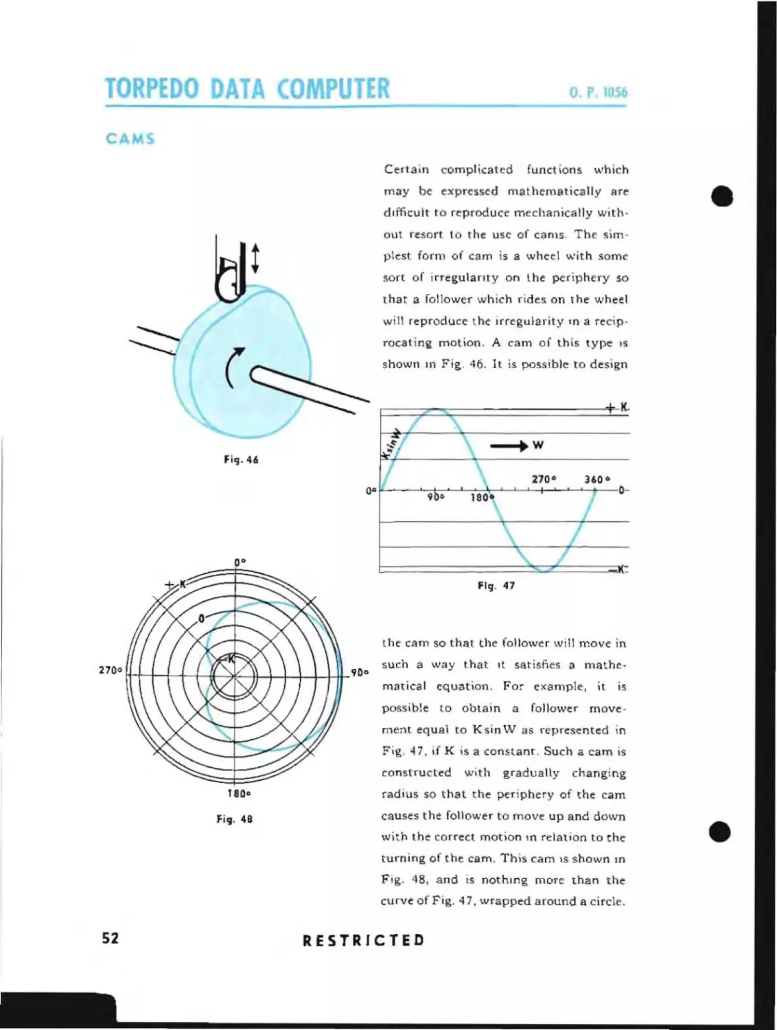
Certain complicated
functions
which
may be expressed mathematically are
difficult to reproduce mechanically without resort to the usc of cams. The sim-
•
piest form of cam is a wheel with some
sort of irregulanty on the periphery so
that a follower which rides on the wheel
will reproduce the irregularity
10
a recip-
rocating motion. A cam of this type
shown
10
IS
Fig. 46. It is possible to design
K-
\ -+W
fi'l- 46
I
\
/
/
Fig. 47
the cam so that the follower will move in
such a way that It satisfies a mathematical equation. For example, it is
possible to obtain a
follower
move-
ment equal to KsinW as represented in
Fig, 47, if K is a constant. Such a cam is
constructed
with
gradually
changing
1800
radius so that the periphery of the cam
fi'l. 48
causes the follower to move up and down
with the correct motion
10
relation to the
turning of the cam. This cam
IS
shown
In
Fig. 48, and is nothing more than the
curve of Fig, 47, wrapped around a circle.
52
RESTRICTED
•
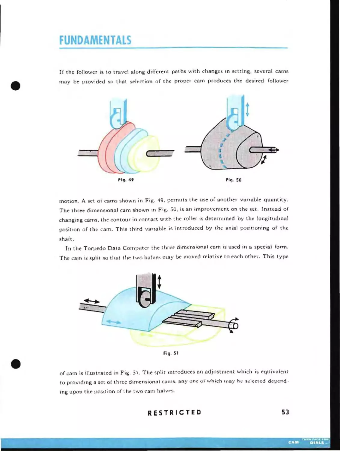
If the follower is to travel along different paths with changes m setting, several cams
may be provided so that ::;elt:'C'tion of the proper enOl produces the desired follower
...
'w
Fig. 50
Fill- 49
motion, A set of cams shown in Fig. 49. permIts the use of another vanable quantity.
The three dimenSIOnal cam shown ,n Fig. 50, is an improvement on the set. Instead of
changing cams, the contour in contact wIth the roller \s deternllned by the longitudmal
position of thc- cam. This third variable is introduced by the axial positioning of the
sha ft.
In the- Torpedo Dala Computer the three dimensional cam is used in a special form,
The cam is slJli\ so thaI the two halves may be moved relative to each other. This type
fig. 51
of cam is illustrated in Fig. 51. The split mtroduces an adjustment which is equivalent
\'0
providIng a set of three dimensional call1S. anyone of which lllay ht' selected depend·
ing upon the pOSll ion of Ihe' lwo cam halv.-s.
RESTRICTED
53
TORPEDO AlA CO
o. P. 1056
DIALS
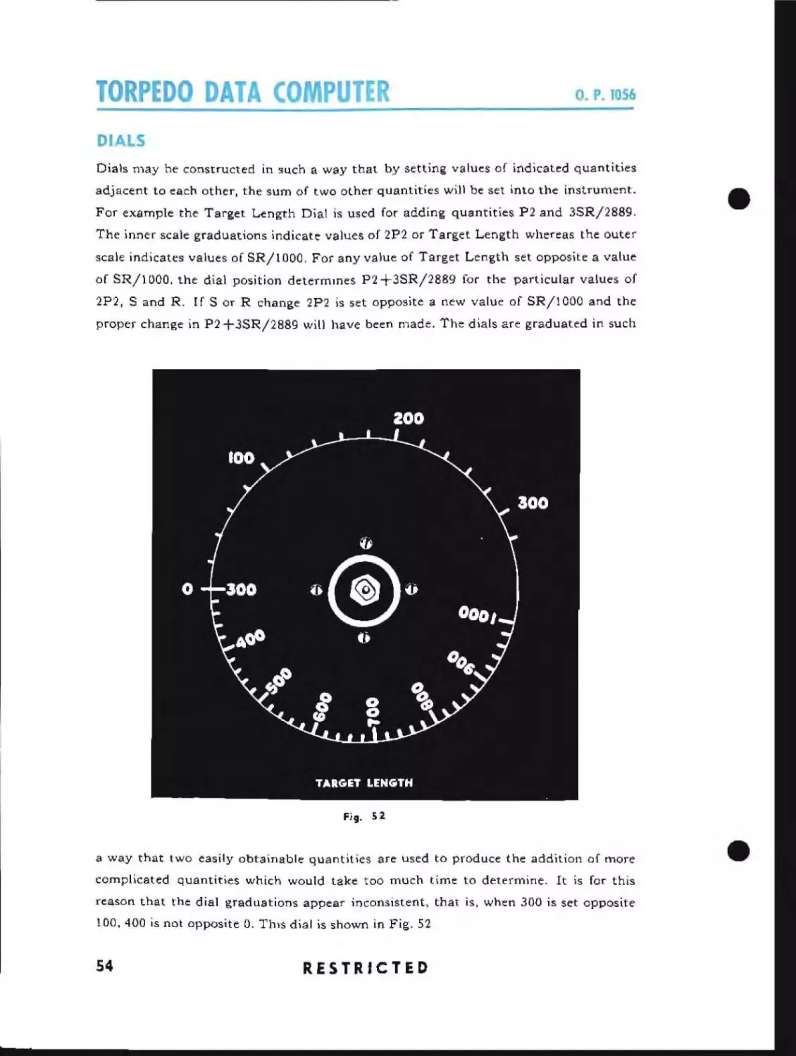
Dials may he constructed in such a way that by setting values of indicated quantities
adjacent to each other, the sum of two other quantities will be set into the instrument.
For example the Target Length Dial is used for adding quantities P2 and 3SR/28S9.
The inner scale graduations indicate values of 2P2 or Target Length whereas the outer
•
scale indicates values of SR/1000. For any value of Target Length set opposite a value
of SRll 000. the dial position determmes P2 +3SR/2889 for the particular values of
2P2, Sand R. If S or R change 2P2 is set opposite a new value of SR/lOOO and the
proper change in P2+3SR/28S9 will have been made. The dials are graduated in such
Fig. 51
a way that two easily obtainable quantities are used to produce the addition of more
complicated quantities which would take too much time to determine. It is for this
reason that the dial graduations appear inconsistent, that is. when 300 is set opposite
100,400 is not opposite O. ThIS dial is shown in Fig. 52
54
RESTRICTED
•
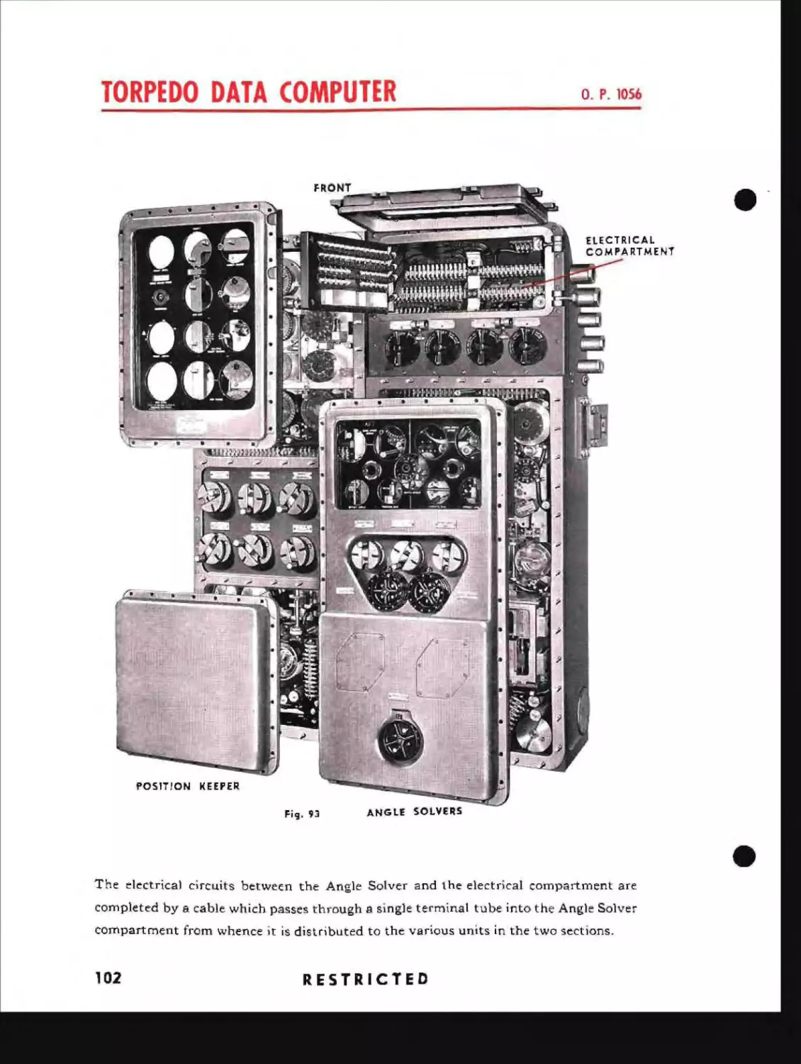
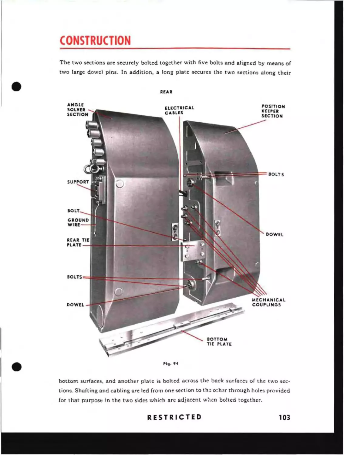
The Torpedo Data Computer is dIvIded into two sections, the first of
which contains the Position Keeper
and the Sound Bearing Converter.
The second sectIon consists of the
fwd and aft Angle Solvers. Each of
these units is made up of smaller
components which may be discussed
independently.
RESTRICTED
55
The Position Keeper receives settings to agree with the initial observations of Relative
Target Bearing and Range as well as estimates of Angle on the Bow and Target Speed.
All of these quantities are set into the instrument with hand cranks. These inputs are
supplemented by contin'uous electrical inputs of Own Course and Own Speed. Using
these quantities the Position Keeper performs the following functions:
a. Assists in correcting the initial estimates.
b. Generates the values of Relative Target Bearing, Range and Target Angle with
respect to Time.
c. Furnishes values of Relative Target Bearing, Range, Target Angle, and Target
Speed mechanically for the fwd and aft Angle Solvers.
d. Furnishes mechanical inputs of Range, Target Angle, and Relative Target
Bearing to the Sound Bearing Converter.
e. Pictorially shows the relative courses of Own Ship and Target and the Track
Angle and Gyro Angles fOT both fwd and aft torpedoes.
f.
Continuously indicates the distance to Target Track.
g. Indicates when the Position Keeper is producing a correct solution for the
particular inputs which have been set in.
The Sound Bearing Converter receives, in addition to the mechanical inputs which
come from the Position Keeper, a cranked-in value of P2 +3SR!2889. The inputs
combine in the instrument to form continuously a value of Sound Bearing which appears on the dials of the Position Keeper. A value of Sound Base Line is set into the
unit to take care of parallax due to the distance between the sound bearing device and
the periscope position for a given ship.
The fwd Angle Solver receives, in addition to the mechanical inputs from the Position Keeper, settings of fwd Offset Angle, Corrected Torpedo Speed as Depth Set,
Torpedo Run Difference and Reach as Keel Depth, and Torpedo Turning Radius. It
also receives adjustments for Tube Base Line and the difference between right and left
values of Reach and Turning Radius. With these inputs it performs the following
functions:
a. Solves the torpedo problem with respect to the torpedoes in the fwd tubes,
allowing for base line between the periscope position and the fwd torpedo tubes.
b. Generates values of fwd Gyro Angle Order and fwd Torpedo Run and transmits
the value of fwd GyTO Angle Order to the fwd Gyro Setting Indicator Regulator.
c.
Indicates when the mechanism is giving the correct solution based upon the
values which it has received.
d. Represents on the Own Ship and Target Dials of the Position Keeper, the fwd
Gyro Angles and fwd Track Angles.
56
RESTRICTED
•
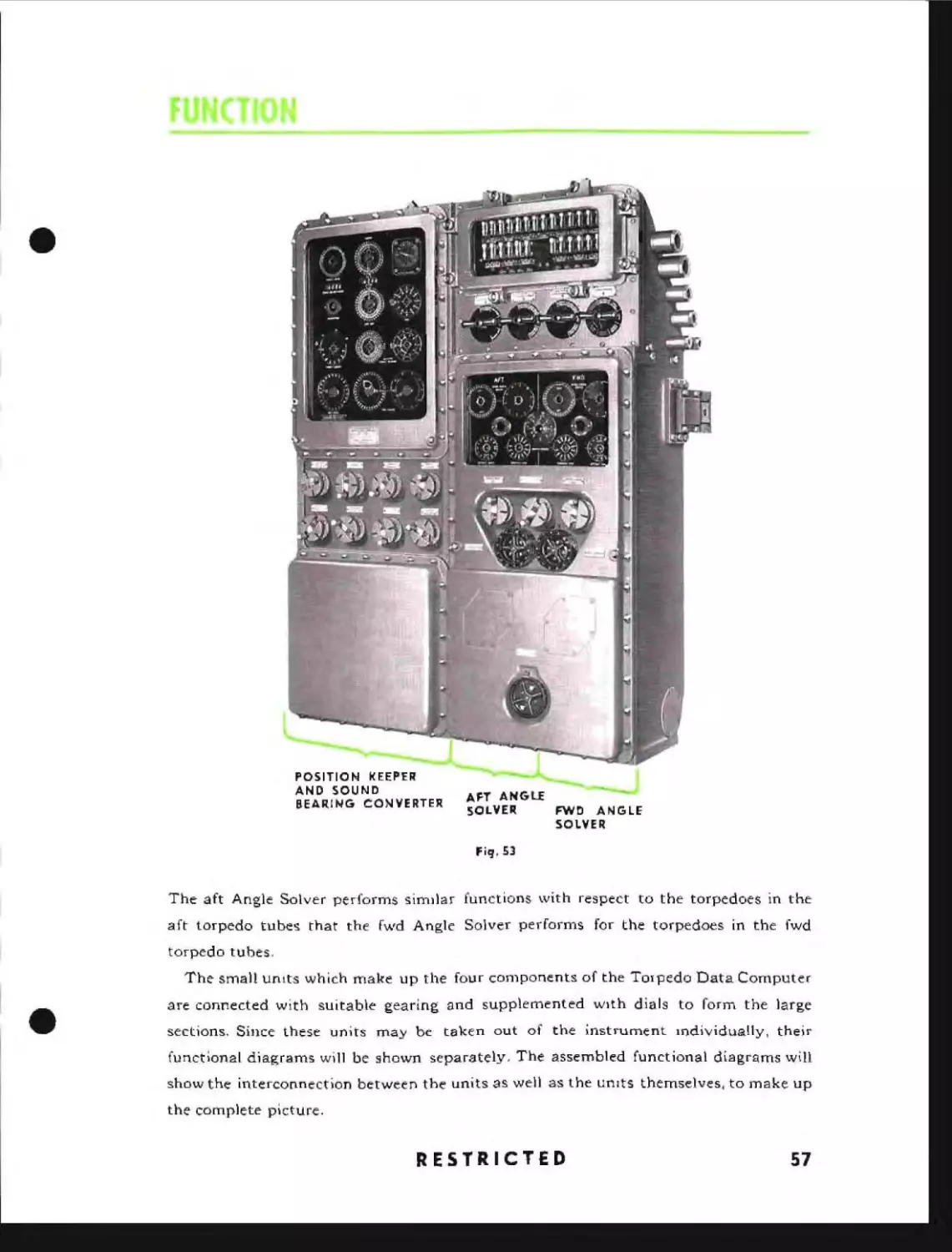
POSITIO N I< EEPER
AND SOUND
BEAR! NG CON VE RTER
AFT ANGU
SOLVER
FWD ANGLE
SOLVER
Fiq,53
The aft Angle Solver performs simIlar functions with respect to the torpedoes in the
aft torpedo tubes that the fwd Angle Solver performs for the torpedoes in the fwd
torpedo tubes.
•
The small units which make up the four components of the TOipedo Data Computer
are connected with suitable gearing and supplemented wIth dials to form the large
sections. Since these units may be taken out of the instrument mdividually, their
functional diagrams will be shown separately, The assembled functional diagrams will
show the interconnection between the units as well as the umts themselves, to make up
the complete picture,
RESTRICTED
57
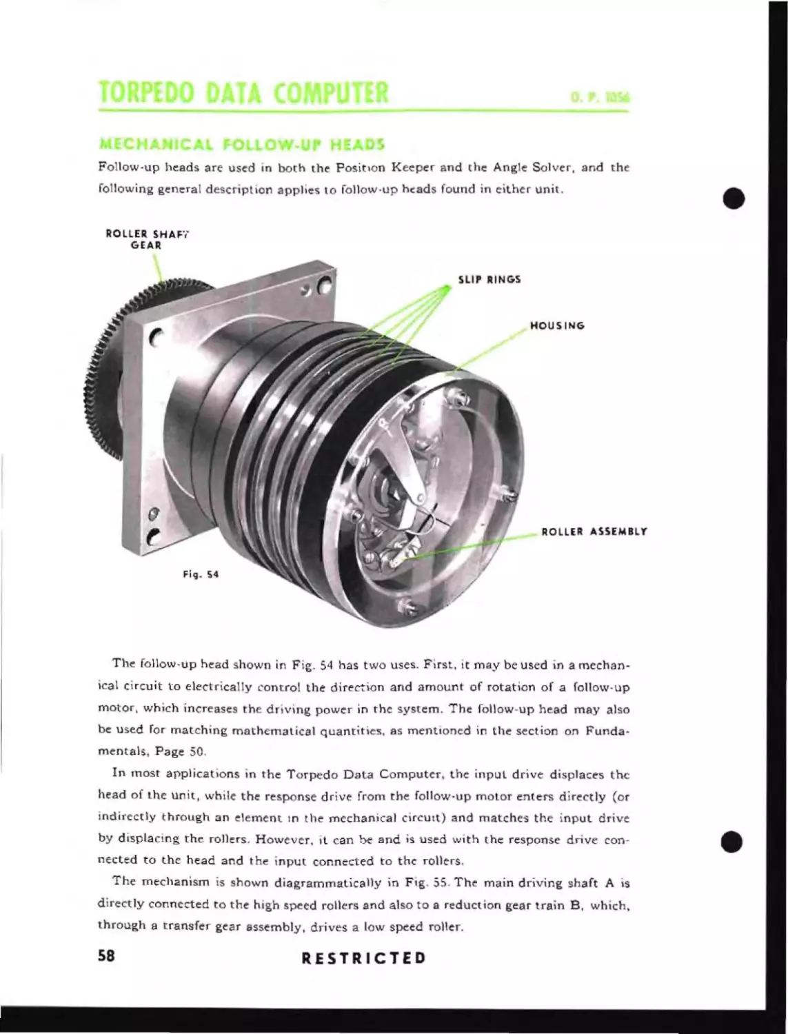
Follow-up heads are used in both the PositIon Keeper and the Angle Solver, and the
following general description applies to follow-up hc:ads found in either unit.
ROLLER SHAFt
GEAR
SLIP RINGS
HOUSING
RO LLER ASSEM BL Y"
Fig_ 54
The follow-up head shown in Fig. 54 has two uses. First, it may be used in a mechanical circuit to electrically control the direction and amount of rotation of a follow-up
motor, which increases the driving power in the system. The follow-up head may also
be used for matching mathematical quantities, as mentioned in the section on Fundamentals, Page 50.
In most applications in the Torpedo Data Computer, the input drive displaces the
head of lhe unit, while the response drive from the follow-up molar enters directly (or
indirectly through an element In the mechanical cirCUIt) and matches the input drive
by displacing the rollers. However, it can be and is used with the response drive coonected to the head and the input connected to the rollers.
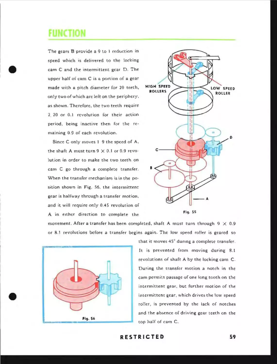
The mechanism is shown diagrammatically in Fig. 55. The main driving shaft A is
directly connected to the high speed rollers and also to a reduction gear train B, which,
through a transfer gear assembly drives a low speed roller.
I
58
RESTRICTED
The gears B provide a 9 to I reduction in
•
speed which is delivered to the locking
cam C and the intermittent gear D. The
upper half of cam C is a portion of a gear
HIGH SPErO
made with a pitch diameter for 20 teeth,
ROLLERS
only two of which are left on the periphery.
as shown. Therefore, the two teeth requ.ire
2. 20 or 0.1 revolution for their action
period, being inactive then for the remaining 0.9 of each revolution.
o
Since C only moves I 9 the speed of A,
the shaft A must turn 9 X 0.1 or 0.9 revo-
C----t.
lution in order to make the two teeth on
B
cam C go through a complete transfer.
When the transfer mechanism is in the position shown in Fig. 56. the intermittent
gear is halfway through a transfer motion.
--A
and it will require only 0.45 revolution of
Fig. 55
A in eIther direction to complete the
movement. After a transfer has been completed, shaft A must tum through 9 X 0.9
or 8.1 revolutions before a transfer begins again. The low speed roller is geared so
that it moves 4S c durmg a complete transfer.
It is prevented from moving during
8.1
revolutions of shaft A by the locking cam C.
During the transfer motion a notch in the
cam permits passage of one long tooth on the
•
intermittent gear, but further motion of the
intermittent gear, which drives the low speed
roller, is prevented by the lack of notches
and the absence of driving gear teeth on the
top half of cam C.
RESTRICTED
59
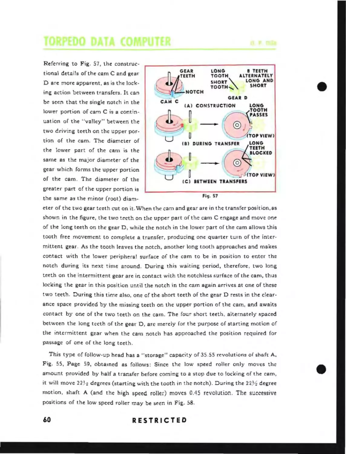
Referring to Fig. 57, the construcLONG
8 TEETH
TOOTH
ALTERNATELY
SHORT \..
LONG AND
TOOTH,\..
SHORT
tional details of the cam C and gear
D are more apparent, as is the locking action between transfers. It can
___~,.,_- NOTCH
GEARD
be seen that the single notch in the
IA) CONSTRUCTION
lower portion of cam C is a cantinuat ion of the "valley" between the
two driving teeth on the upper portion of the cam. The diameter of
~
(0.",:
~j
U
0,
lTOP VIEW)
DURING TRANSFER
gear which forms the upper portion
u
LONG
TEETH
BLOCKED
~
same as the major diameter of the
@~J~
0
(8)
the lower part of the cam is the
of the cam. The diameter of the
_
LONG
TOOTH
,PASSES
~
ICI BETWEEN
greater part of the upper portion is
the same as the minor (root) diam-
Fig. 57
eter of the two gear teeth cut on it. When the cam Bnd gear are in the transfer position, as
shown in the figure, the two teeth on the upper part of the cam C engage and move one
of the long teeth on the gear D, while the notch in the lower part of the cam allows this
tooth free movement to complete a transfer, producing one quarter turn of the intermittent gear. As the tooth leaves the notch, another long tooth approaches and makes
contact with the lower peripheral surface of the cam to be in position to enter the
notch during its next time around. During this waiting period, therefore, two long
teeth on the intermittent gear are in contact with the notchless surface of the cam, thus
locking the gear in this position until the notch in the cam again arrives nt one of these
two teeth. During this time also, one of the short teeth of the gear D rests in the clearance space provided by the missing teeth on the upper portion of the cam, and awaits
contact by one of the two teeth on the cam. The four short teeth. alternately spaced
between the long teeth of the gear D, are merely for the purpose of starting motion of
the intermittent gear when the cam notch has approached the position required for
passage of one of the long teeth.
This type of follow-up head has a "storage" capacity of 35.55 revolutions of shaft A.
Fig. 55, Page 59, obtamed as follows: Since the low speed roller only moves the
amount provided by half a transfer before coming to a stop due to locking of the cam,
it will move 2H2 degrees (starting with the tooth in the notch). During the 22Y.i degree
motion, shaft A (and the high speed roller) moves 0.45 revolution. The successive
positions of the low speed roller may be seen in Fig. 58.
60
RESTRICTED
•
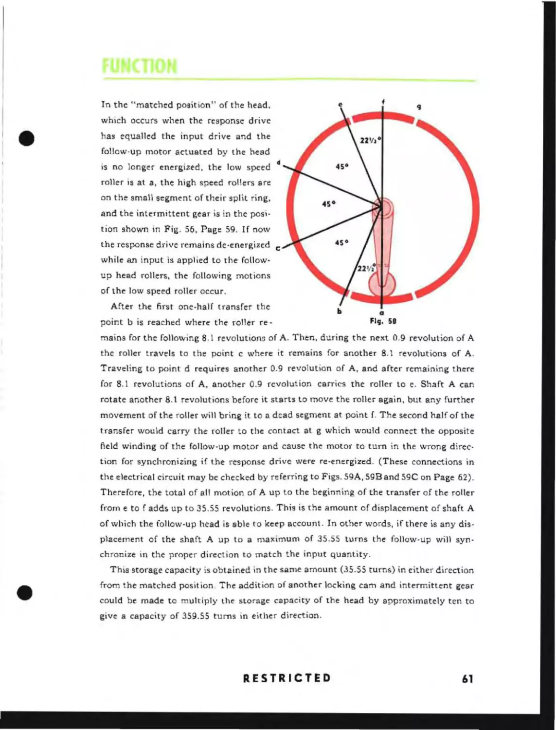
In the "matched position" of the head.
which occurs when the response drive
has equalled the input drive and the
follow-up motor actuated by the head
is no longer energized. the low speed
d
roller is at a, the high speed rollers are
on the small segment of their split ring,
snd the intermittent gear is in the position shown in Fig. 56, Page 59. If now
the response drive remains de-energized c
while an input is applied to the followup head rollers, the following motions
of the low speed roller occur.
After the first one-half transfer the
b
point b is reached where the roller re -
a
FICJ. 58
mains for the following 8.1 revolutions of A. Then, during the next 0.9 revolution of A
the roller travels to the point c where it remains for another 8.1 revolutions of A.
Traveling to point d requires another 0.9 revolution of A, and after remaining there
for 8.1 revolutions of A, another 0.9 revolution carries the roller to e. Shaft A can
rotate another 8.1 revolutions before it starts to move the roller again, but any further
movement of the roller will bring it to a dead segment at point f. The second half of the
transfer would carry the roller to the contact at g which would connect the opposite
field winding of the follow-up motor and cause the motor to tum in the wrong direction for synchronizing if the response drive were re-energized. (These connections in
the electrical circuit may be checked by referring to Figs. S9A, 5gB and 59C on Page 62).
Therefore, the total of all motion of A up to the beginning of the transfer of the roller
from e to f adds up to 35.55 revolutions. This is the amount of displacement of shaft A
of which the follow-up head is able to keep account. In other words, if there is any displacement of the shaft A up to a maximum of 35.55 turns the follow-up will synchronize in the proper direction to match the input quantity.
•
This storage capacity is obtained in the same amount (35.55 turns) in either direction
from the matched position. The addition of another locking cam and intermittent gear
could be made to multiply the storage capacity of the head by approximately ten to
give a capacity of 359.55 turns in either direction.
RESTRICTED
61
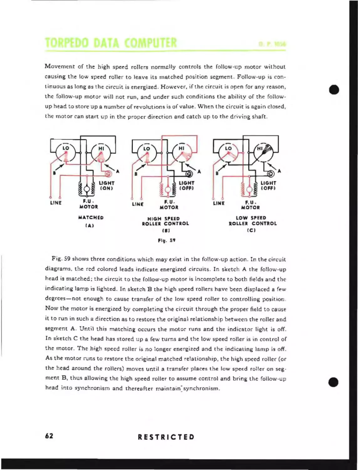
Movement of the high speed rollers normclly controls the follow-up motor without
causing the low speed roller to leave its matched position segment. Follow-up is continuous as long as the circuit is energized. However, if the circuit is open for any reason,
the follow-up motor will not run, and under such conditions the ability of the followup head to store up a number of revolutions is of value. When the circuit is again closed,
•
the motor can start up in the proper direction and catch up to the driving shaft.
LINE
F.U.
MOTOR
MATCHED
fA)
LINt
F.UMOTOR
LINt
HIGH SPEED
ROLLER COIliTROL
III
f.U.
MOTOR
LOW SPEED
ROLLER CONTROL
eCI
Fig- S'
Fig. S9 shows three conditions which may exist in the follow-up action. In the circuit
diagrams. the red colored leads indicate energized circuits. In sketch A the follow-up
head is matched; the circuit to the follow-up motor is incomplete to both fields and the
indicating lamp is lighted. In sketch B the high speed rollers have been displaced a few
degrees-not enough to cause transfer of the low speed roller to controlling position.
Now the motor is energized by completing the circuit through the proper field to cause
it to run in such a direction as to restore the original relationship between the roller and
segment A. Until this matching occurs the motor runs and the indicator light is off.
In sketch C the head has stored up a few turns and the low speed roller is in control of
the motor. The high speed roller is no longer energized and the indicating lamp is off.
As the motor runs to restore the original matched relationship, the high speed roller (or
the head around the rollers) moves until a transfer places the low spet:d roller on segment B, thus allowing the high speed roller to assume control and bring the follow-up
head into synchronism and thereafter maintain~synchronism.
62
RESTRICTED
•
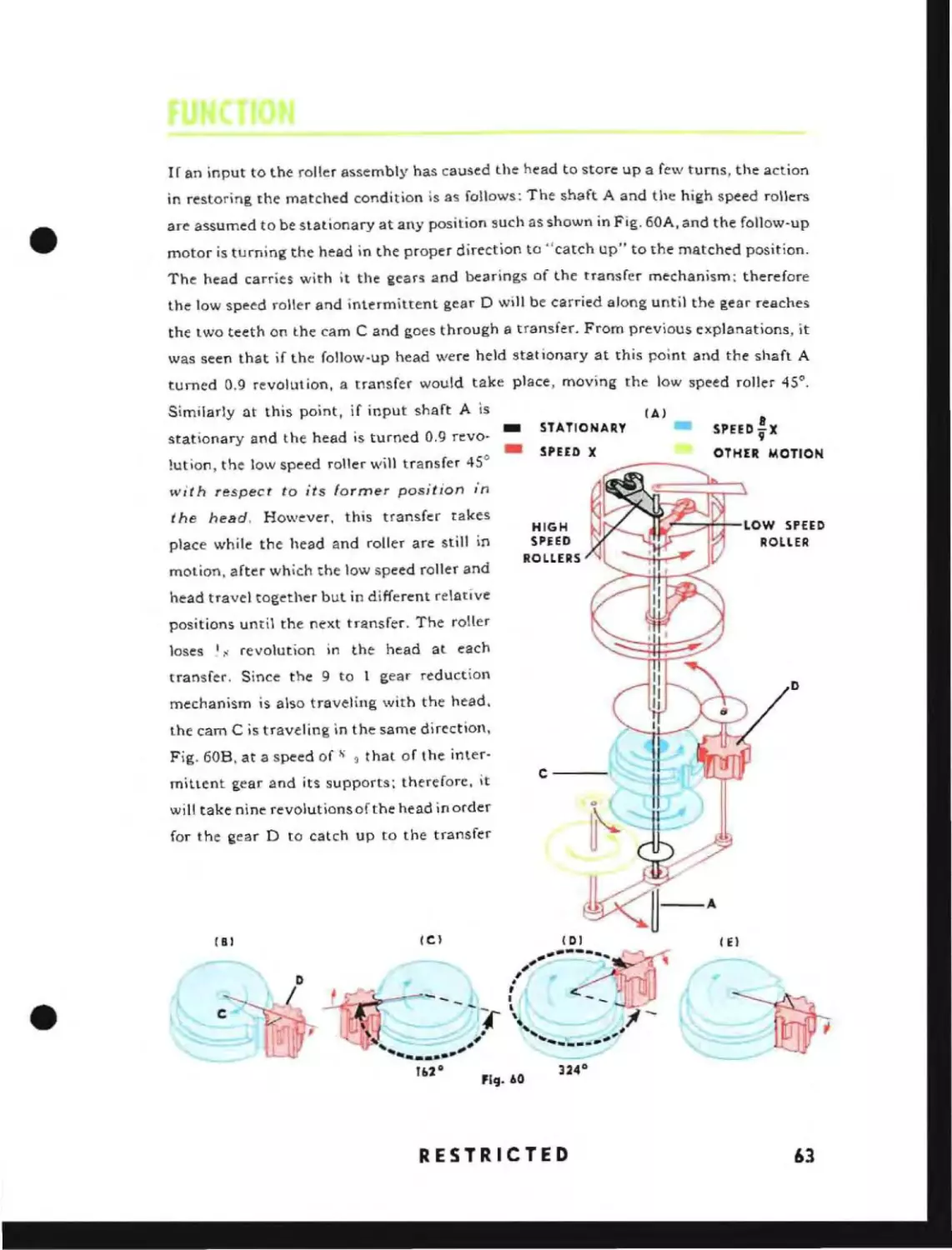
If an input to the roller assembly has caused the head to store up a few turns, the action
in restoring the matched condition is as follows: The shaft A and the high speed rollers
are assumed to be stationary at any position such as shown in Fig. 60A, and the follow-up
motor is turning the head in the proper direction to "catch up" to the matched position.
The head carries with it the gears and bearings of the transfer mechanism: therefore
the low speed roller and intermittent gear 0 will be carried along until the gear reaches
the two teeth on the cam C and goes through a transfer. From previous explanations, it
was seen that if the foHow-up head were held stationary at this point and the shaft A
turned 0.9 revolution, a transfer would take place, moving the low speed roller 45".
Similarly at this point, if input shaft A is
stationary and the head is turned 0.9 revo!ution, the low speed roller will transfer 45°
(Al
~X
_
STATIONARY
SPEED
-
SPEED X
OTHER MOTION
with respect to its former position in
the head, However, this transfer takes
place while the head and roller are still in
motion, after which the low speed roller and
HIGH
j[r=----:~I__LOW
SPHD
SPEED
ROLL ER
ROLLERS
head travel together but in different relative
positions until the next transfer. The roller
loses
,I.,
revolution in the head at each
transfer. Since the 9 to 1 gear reduction
o
mechanism is also traveling with the head.
the cam C is traveling in the same direction,
Fig. 60B, at a speed of
S ~
that of the inter-
mittent gear and its supports; therefore. it
C---'~
will take nine revolutions of the head inorder
for the gear D to catch up to the transfer
IE)
(Ill
•
RESTRICTED
63
teeth of cam C and complete another transfer. See Figs. 60B, 60C, 60D, and 60E, Page
63. This sequence of transfers continues until a final transfer brings the low speed roller
onto the segment which transfers control to the high speed rollers. The high speed rollers
then bring the follow-up head to its matched position and continue to keep it matched.
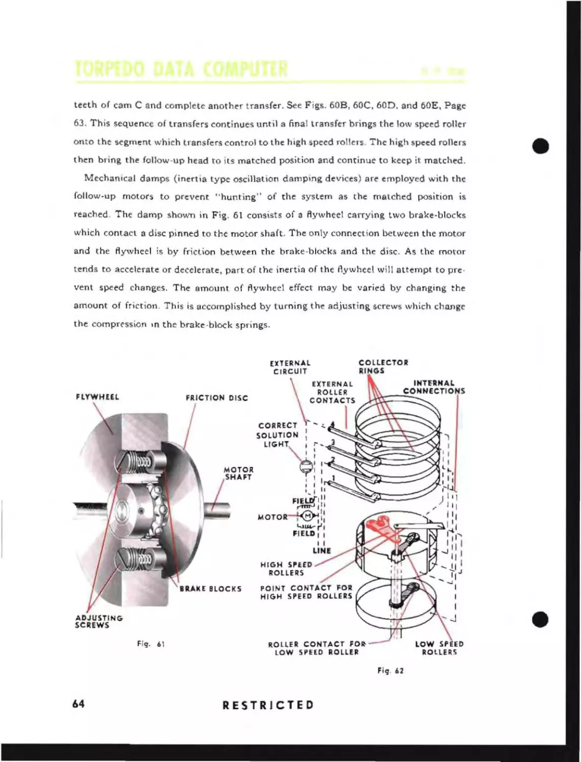
Mechanical damps (inertia type oscillation damping devices) are employed with the
follow-up motors to prevent "hunting" of the system as the matched position is
reached, The damp shown in Fig. 61 consists of a flywheel carrying two brake-blocks
which contact a disc pinned to the motor shaft. The only connection between the motor
and the flywheel is by friction between the brake-blocks and the disc. As the motor
tends to accelerate or decelerate, part of the inertia of the flywheel will attempt to pre·
vent speed changes. The amount of flywheel effect may be varied by changing the
amount of friction, This is accomplished by turning the adjusting screws which chunge
the compr<"ssion In the brake-block springs.
COLLECTOR
RINGS
EXTERNAL
CIRCUIT
FLYWHEEL
EXTERNAL
ROLtER
CONTACTS
DISC
CORRECT
SOLUTION
I
1
lIGHT"¢:: '
I I
I I
I
,
1 I
t
',I I,
FIEWI"
~III
~II
MOTOK~II
"->uvrl
FIELD I I
I I
LINE
HIGH SPErO
ROLLERS
ADJUSTING
SC~EWS
Fig. 61
ROLLER CONTACT FO~
LOW SPEED ROLLER
Fig. 62
64
RESTRICTED
•
The spacing of the high speed rollers, with respect to the width of their zero segment,
•
is adjustable. so as to obtain high sensitivIty of control at the matched position of the
follow-up head. See Page 250. The greater the space between rollers, the less they will
have to move in either direction to make contact with a field segment and energize the
follow-up motor; hence, the greater the sensitivity. The internal electrical connections
of the 4-ring follow-up head are shown in Fig. 62.
Another use of the follow-up head is in conjunction with synchro motors where a
quantity is transmitted at two speeds. In this case the high and low speed rollers are
driven directly by separate synchro motors and the "transfer" of control is done electrically by means of a 4-ring follow-up head on the low speed synchro.
OWN
SPEED
OWN
COURSE
HAND
HAND
CRANI(
CRANK
SWITCH
~ ~
: SWITCH
~
-:-=-~
...
nJ--;........,H-<~n.-....
Fig. 63 shows how the Own Course input is amplified by means of a motor controlled
by 1 and 36-speed synchros. In this case the follow-up heads are not equipped with
transfer gearing but together are capable of input "storage" by virtue of the electrical
"transfer" ratio between high and low speed rollers.
The Own Speed input is also shown in this figure to illustrate the principle of control
of a motor by means of a 3-ring non-storing type of follow-up head.
RESTRICTED
65
I So
20
•
dT
So
5 dT
S
SS
dT
2S
sin A.
5S
JS
A
cos A
fS
36
SS
sin A dT
cos A. dT
dT
S So
sin Br dT
~~~rT'+2e
Br_.~. ._~.....
~
f
I So
So cos Br d
dT
) S si n A d T
I'
fig.
66
64
RESTRICTED
S
COl
A dT
+
+
j So ,in Br dT
=
RL. B
j So
=
l::. R
Co,
fir dT
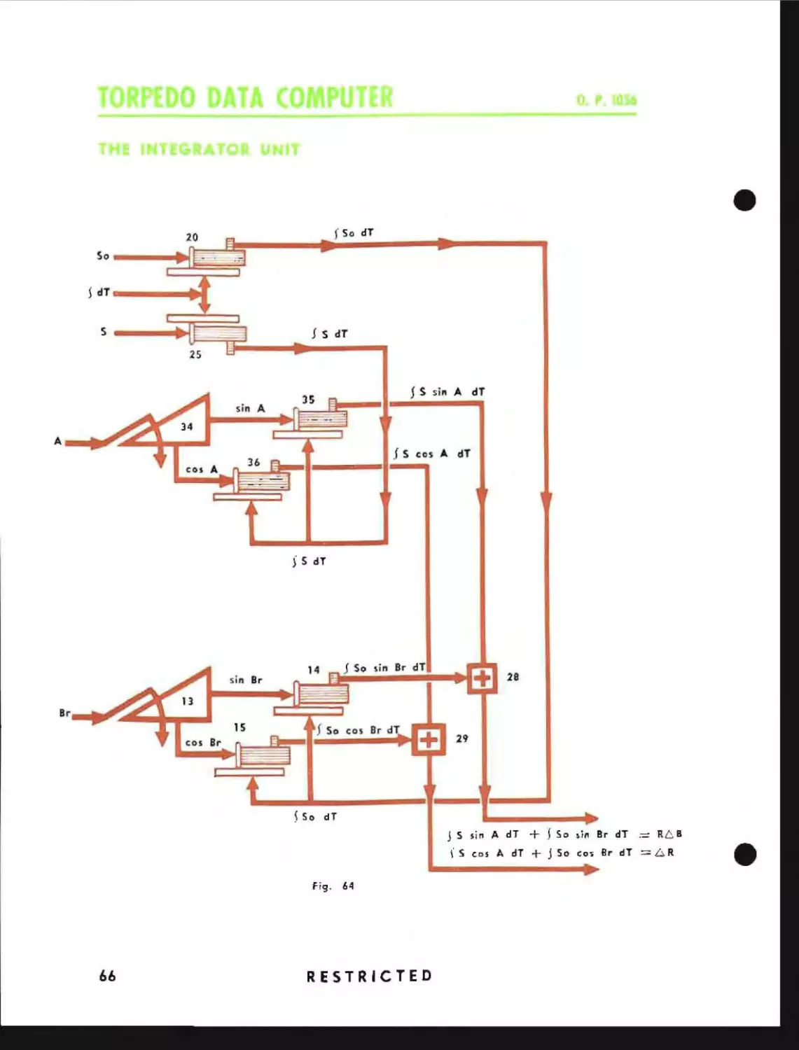
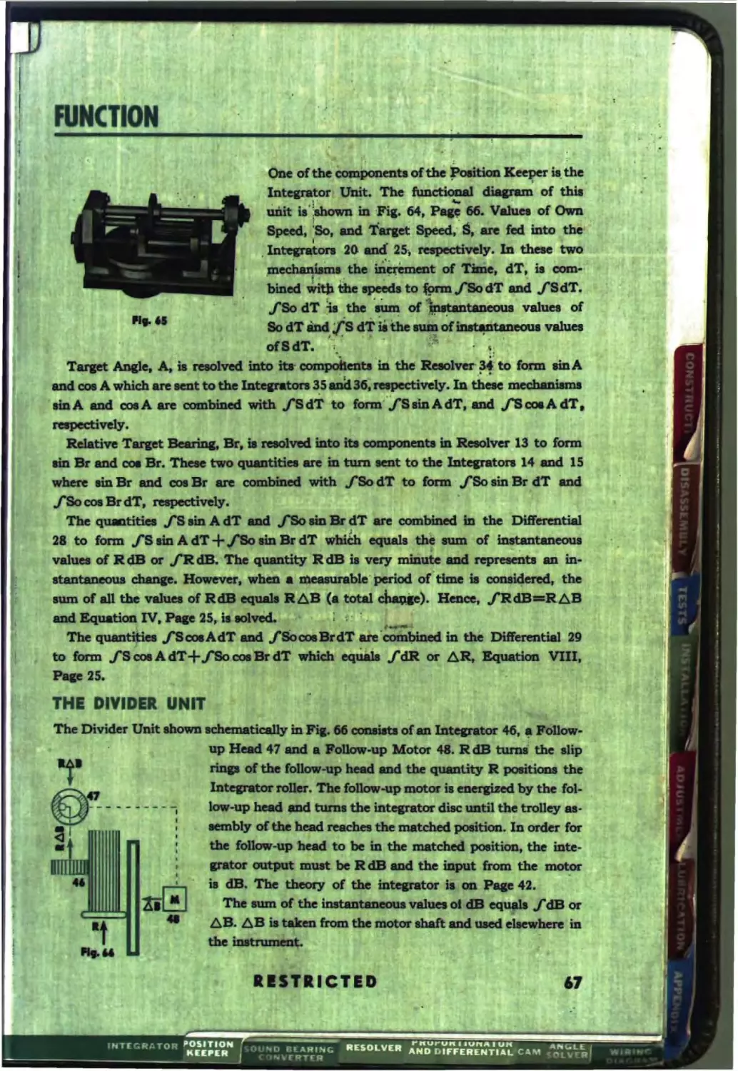
ODe oftbe ~ oftb8 ~ Keeper ia. the
•
•
•
J
lDtcpator!
mdt. The ftmctiane1
~ of thia
\'
4.,.UDit ia':.bown iD ·Pia. 64, p. . . Valuee of 0wD
pced~ ~So, ad
Speed,.are fed iDto the
T.aet
t
25, teiipik:tifely. 1D thae two
the ~t 01
• dT, ia
biDed WItIl the ape8d1 to fprm
ciT ad fSdT.
r
"flo dT it the IUID of,
taDc:ma va1uel of
.1DtepIItOn 20
,meciM.,..m.,
......
com-
cIT
,~ 'iithe ~'~~valuea
of clT.;.
,1. "
Tarpt ADele. A.' redved bItD ItaiD the . . . . .·301· to form aiDA
aDd cae A which are teDt to the lDtetPatol'I35 . I
ftly. In ~ lJ"'dwniam.
aiDA aDd caeA an ccmbbMd with .f8dT to fonD"'.rsaIDAdT. aDd .f8caaAdT•
O'
. . . . .tiftly.
Relative Tarpt s.riDI. . , ' nlIOIved iato
componeatt ill Reeolver 13 to fonn
aiD
aDd caa Br. Tbete two eau-tltiet are in tum Ialt to the lDtepaton 14 aDd 15
-'-- aiD Br aDd caa. are
with fSodT to fonD, fSo lin Br dT aDd
f&o cae Br dT, napectlwly.
The quatm.
aiD A clT . . flo.. dT are ccmbiDed III the Differential
21 to fann .f8 liD A cIT
ciT')
tbi aum of iDatantaneou8
va1UM of dB or jR dB. TIMi q\l8tity R dB ia very ~ ad lepraeDa aD in8taDtM"OUl c:benp. Ho.e~,
' • 1DeMm'abIe' period of-time. CODIidered, the
MUD or aD the nJua or RdB tlq1JM RAB ( total cbao.Ie). HeDce, jR@ RAB
.rs
+
Bquaticxa IV. PIlle 25,. is
."
.i
~:
:.
The quaD • fScoeAdT.cl ftIocaa ciT ate'c:aIDbiDed in the Dlft'ereotial 29
to fonD fS~AdT+.f80.cae.clT
'
fdR or AR, Bqllatioa VlD,
equw.
25.
TH
The Divider UDit tbotlrD
cx.1iIa or_
46, . MIkM
Nlow-up Motor .... R dB turU the a1ip
aDd the ~ podic:Im the
foDOw-up motOI' Ia eaerataect by the fol-up
.-I turDt the intepator dille uatil the trolley . .embly of the he.-d racha the matched poIitioD. In order for
to .be in the matched poeition, the iDtel1'li*01 OlL1tJllR IIR18t be dB aDd the iaput from the ~
it dB. The tbeoIy or the iDtcpator .. OIl Pap 42.
The IUID or the .
va1aeI
JdB 01'
AS. AB
from the motor abaft: aDd uted eltewbere ill
In operating the Position Keeper, estimates of Target Speed. Angle on the Bow and
Initial Range, and a measure of Initial Relative Target Bearing are made by observation and introduced into the instrument manually. Own Course and Own Speed are
received continuously in the Position Keeper by synchro transmission. A Time Motor
will then continuously generate values of Present Range, Relative Target Bearing and
Target Angle based upon the inputs. These values are continuously changing with
motion of Own Ship and Target, and are continuously indicated on dials on the
instrument.
If the initial estimates were correct, new values obtained from a second observation
will agree with the values shown on the instrument. If the initial estimates were
incorrect a more accurate setting of the Position Keeper may be made based upon
new estimates as well as the amount and direction of the error which was found. Subsequent observations will allow still more accurate setting of the instrument, until.
finally, further observations will agree with the generated values of the instrument,
and show that the Position Keeper is maintaining the position ofrhe Target. The Position Keeper will continue to maintain the position of the Target as long as Target
Course and Target Speed do not change. If either Target Course or Target Speed
changes. new estimates will have to be introduced and corrected by subsequent observations until the Position Keeper again maintains the position of the Target.
The inter-relation of the generating and associated circuits of the Position Keeper
is shown on the functional diagram Fig. 67, Page 68A.
Own Speed, So, is received at l-speed by synchro transmission on Synchro 16.
It is indicated on a dial attached to Follow-up Head 17, and, by means of Follow-up
Head 17 and Follow-up Motor 18, positions the roller in Integrator 20. Own Course,
Co, is likewise received
by synchro transmission at I and 36 -speed on Syn.
chros 1 and 2. It is indicated on dials attached to Follow-up Heads 3 and 4, and by
means of Follow-up Heads 3 and 4 and Follow-up Motor 5 is introduced into Differential 7. When power is turned on, these follow-up motors become energized, and also
Time Motor 23_ This Time Motor, controlled by Time Motor Governor 24, drives the
discs of Integrators 20 and 25 and indicates elapsed Time on Dial 26.
RESTRICTED
69
When it is decided to "track" a Target, an estimate of Target Speed, S, is made and
introduced into the instrument by turning Handcrank 37 until the value of estimated Target Speed appears on Dial 38. This value of Target Speed positions the rolter
on Integrator 25 and is also transmitted to the Angle Solver.
Integrator 2S multiplies Target Speed with instantaneous Time producing a value
of Target travel. This value rotates the discs of Integrators 3S and 36. Integrator 20
multiplies Own Speed, So, with instantaneous Time and continuously adds these
products producing a value of Own Ship's travel. This value rotates the discs of
Integrators 14 and 1S.
Relative Target Bearing, Br, is measured and the Target Bearing Handcrank, SO, is
turned until the measured value of Relative Target Bearing appears on Dials 10 and 11.
Initial True Target Bearing, iB. is actually introduced into the instrument and is added
to Own Course, Co, by Differential 7 to produce Relative Target Bearing, Br, Equation
XI, Page 25. Relative Target Bearing is transmitted to the Angle Solver, the Sound
Bearing Converter, and to Dial 12. This value is also resolved into its components by
Resolver 13 to produce values of sin Br and cas Br.
Sin Br positions the roller of Integrator 14. Integrator 14 multiplies the instantaneous sine of Relative Target Bearing and instantaneous Own Ship's travel and can·
tinuously sums up these instantaneous products, ISo sin Br dT, which are fed to
Differential 28.
Similarly cOs Br positions the roller of Integrator 15. This Integrator multiplies the
instantaneous cosme of Relative Target Bearing with instantaneous Own Ship's travel
and continuously adds up these instantaneous products, fSocosBrdT, which are fed
to Differential 29.
An estimate is made of the Angle on the Bow, Ab. Target Course Handcrank 31 is
turned until this estimated value appears on Dial 30. Although Target Course, C, is
actually introduced into the instrument it is added to True Target Bearing, B, by
Differential 33. The gear mesh of this differential is such that 180 0 is added to True
Target Bearing. This solves Equation XII on Page 25 and produces Target Angle, A.
Although Target Angle is produced it is read as Angle on the Bow since Dial 30 is
graduated from 00 to 180 0 port and starboard. Target Angle is transmitted to the
Angle Solver, the Sound Bearing Converter and to the Distance to Track Indicator 71.
70
RESTR'CTED
Target Angle is also resolved into its components by Resolver 34, to produce values of
sin A and cosA.
Sin A positions the roller of Integrator 35. This integrator multiplies the instantaneous sin A by instantaneous Target travel and continuously sums up the instantaneous products, j"S sinAdT, which are fed to Differential 28. After a finite period of
time Differential 28 will have received total values equal to the sum of the instantaneous products.
Similarly cos A positions the roller of Integrator 36. This Integrator mUltiplies the
instantaneous cos A with instantaneous Target travel, and continuously sums up these
instantaneous products, fS cos A dT, which are fed to Differential 29. After a finite
period of time Differential 29 will have received total values equal to the sum of the
instantaneous products.
Differential 29 adds its two inputs solving Equation VIII on Page 25 and producing
continuously Change of Range, 6R=fdR, which is fed to Differential 53. An initial
estimate of Range is made and introduced into tbe Position Keeper with Range Hand·
crank 45. Change of Range, 6R, is continuously added to the initial estimate of
Range by Differential 53. Thus, Present Range is continuously maintained and is indicated on Counter 61. This value of Range is transmitted to the Distance to Track
Indicator and also positions the roller of Divider Unit 46.
Change of Range also positions Follow-up Head 40 so that Follow-up Motor 41 will
produce a value of Change of Range but with amplified power. This value of Change of
Range is added to Initial Range by Differential 42. The resultant value Range is indicated on Counter 43, and is continuously transmitted to the Angle Solver and the
Sound Bearing Converter.
Differential 28 adds its inputs to solve Equation IV on Page 2S producing R 6B.
This value operates the Follow-up Head 47 and in conjunction with the Range input
into the Divider Unit solves Equation X, Page 2S and causes Follow-up Motor 48 to
produce a value of Change of True Target Bearing, 6.B=fdB. Since at each instant
dR and R dB are being produced from the instantaneous values of the same funda·
mentsl quantities, the only difference being the particular components of these Quan·
tities which are used, the R that is introduced into the Divider Unit will always correspond to the instantaneous R dB that is being divided_ This Change of True Target
RESTRICTED
71
Bearing IS added to the initial estimate of True Target Bearing by Differential 49.
Thus, the Position Keeper makes use of True Target Bearing which is continuously
corrected as it changes due to the motion of Own Ship and Target.
The continuously corrected value of True Target Bearing acts through Differentials
7 and 33 to produce continuously Relative Target Bearing and Target Angle respectively. These values continuously re-enter the generating circuits of the Position
Keeper, where they function so as to have incrementnl changes added to themselves.
and to produce the incremental changes in Range. In this manner the position of
the Target is continuously maintained.
Corrections made to the original estimates are added in by the various dIfferentials.
The respective integrator rollers are re-positioned thus relocating the respective
follow-up heads. The follow·up motors Quickly match the new values and generation
continues. This is equivalent to starting a new problem where the initial inputs differ
only slightly from the initial values existing in the instrument.
Aiter the values of S. C, is, and iR are introduced the Time Dial is turned back to
zero by uSing Handcrank 27 which turns the dial through Differential 6. This allows
a continuous log to be kept of the sequence of the steps in the solution. The values of
Range and Target Angle operate in the Distnnce to Track IndIcator to indicate continuously the distance from Own Ship to the track of the Target. This indicator operates as the resolver described on Page 47.
Values of Gyro Angle minus Relative Target Beanng, G -Br, from both fwd and aft
Angle Solvers are received by Target Dial 30 and Own Ship Dial 12. These values actuate parts of arrows that move relative to the inner parts of these dials.
The outer ring part of Dial 30 receives a value of True Target Bearing but is geared
w that when read against the index, it indIcates True Target Bearing minus) 80° and
has no significance as far as the operation of the instrument is concerned. The inner
part of Dial 30 receives a value of Target Angle but is graduated so that when read
against the Index it indicates Angle on the Bow. When the zero of the Inner member of
Dial 30 is read against the ring dial, Target Course
IS
mdicated. When the arrow tails
on this dial are read against the inner member, the Track Angles for both fwd and aft
torpedoes are indicated.
True Target Bearing
72
IS
also received by the ring part of Dial 12 and when read
RESTRICTED
•
against its index indicates True Target Bearing. The inner member of this' dial receives
a value of Relative Target Bearing and when read against the index indicates Relative
Target Bearing. When the zero of the inner member is read against the outer member
Own Course is indicated. Further, when the arrow-heads on this dial are read against
the inner member the Gyro Angles for both fwd and aft torpedoes are indicated.
Dial 32 is a high-speed dial indicating a vernier value of Target Course and is only
used in testing the instrument.
Handcranks 21 and 8 allow manual input of Own Speed and Own Course in case of
failure of their respective follow·up systems. Switches 22 and 9 prevent the possibility of
the follow-up motors being energized while the handcranks are engaged.
Own Speed, Target Speed and Range are limited by positive stops to prevent values
beyond the limits of the instrument from being introduced with the attendant possibilities of damage. Stop 44 has a lower limit of 300 yards as lesser values are beyond the
operational limits of the Sound Bearing Converter and the Angle Solver. Switches 66
and 59 act to de-energize the Change of Range Follow-up Motor 41 when the limits of
Stop 44 are encountered.
Signal light 55 is connected between Follow-up Heads 40 and 47 and indicates when
the follow-up heads are both synchronized. This is an indication that the Positicn
Keeper has solved the problem based upon the inputs it received and is maintaining
this solution. It should here be noted that the light will be extinguished if at short
ranges the change in Bearing exceeds the capabilities of the instrument. Further, if the
Range decreases below 300 yards as in a cotlision run by the Target, the light witl also
go out.
Time Counter 70 indicates the total time that the instrument has been in operation.
This time counter is located inside the instrument and is shown in Fig. 96 on Page 105.
The functional diagram, Fig. 67, Page 68A, shows the functions performed by the
individual units of which the Position Keeper is comprised. A unit assembly diagram
is shown in Fig. 71, Page 7BA.
The differences between the various Mods. of the Mk. 3 Data Computer are either
differences in terminal tubes. differences in the gearing to Own Speed Integrator or
both. The terminal tubes for the various Mods. are shown on the elementary wiring
diagram. The differences in gearing to Own Speed Integrator are due to different speeds
of transmission of Own Speed from the Ship's Log. That is, differences in the actual
number of degrees of rotation of Own Speed Synchro Receiver for a difference of one
knot in Own Speed. On the gear diagram, Fig. 58, Page 75A,
RESTRICTED
IS
a chart of the various
73
Mods. from Mod. 5 to Mod. 12, indicating the ship to which each
Mod. is assigned, the range of the log together with the range of
Own Speed Stop, and the number of teeth on the three gears which
become affected. The letter "S" after a number indicates that the
gear is spirally cut.
The Mk. 3 Mods. 10 and 11 Torpedo Data Computers are used
on submarines where the Ship Log transmits Own Speed nonlinearly. This means that in going from one speed to another at
one part of the Own Speed Dials, the Own Speed Follow-up Motor
must make more or less turns than in going from one speed to
another at another part of the dial. In order that the Own Speed
Follow-up Motor shall position Own Speed Follow-up Head cor·
rectly and hence position the roller of Integrator 20 correctly. it
IS
caused to run non-linearly with respect to the angUlar rotation of
the dial by the introduction of a cam. This cam and its attendant
gearing are shown on the gear diagram, Fig. 68.
The Mk. 3 Mod. 9 Torpedo Data Computer is used in conjunction
with other equipment for instruction purposes only. It operates in
an identical manner with the other Mods., but has additional
mechanical outputs of Range and Relative Target Bearing which
are transmitted to a data recorder. ThiS recorder may be seen on
the top of the instrument in Fig, 2, Page 9. The use of this instrument for instruction purposes is beyond the scope of this manual,
but will be found in O.D. 2110.
Torpedo Data Computers manufactured at this time are equipped with Distance to Track Indicators. However, instruments now
in serVlce will not be changed due to contemplated further modification. These older instruments have in place of the Distance to
Track Indicator, a high speed Target Course Dial with a concentric
low speed Target Course ring Dial.
74
RESTRICTED
•
----
-
-~---
-
~
-
-
-
BeariDa CoD~ ia mu.trated in Fig.
ahOI'IIl in Pic. 69. A value of cme-ba1f Taqet 1eqth
The SouDcl
aloac ita caune duriDI the time of
the iDatrumeDt manually. To .
Ranae • read from the diala-' the
-
~
-
-~------
70 ad ita fuactinneI
from
the
T
the 'I
to Own
T
•
1. • Tbia
tively limple calculation. HaudcnDk 57 is turDed UDtil aD
ia
•
of total
T~ Leqth, 2P2, is poBitioDecl oppoaite thia ~ of SR/1000, OIl DW 51. The
il 10
4ia1
calibrated that the function that ia actually mbo4uced IDtO the U:wtI ument •
P2 +3SR/2889.
.
.. Target Anale, A, is COIltinuoul1y received from the Poatbl Keeper . . ia r-.a..d
into ita compoDeDta in Re.otver 62. The
ame
P2+3SR/2889, ~U8 101~ equatiaD XIII em P8Ie 27.
ia here IIIIIltiPliId
-
.
.-". ,,-
::
,-
..... ' •.... ~.:: :-:.. :;.: ...:;._ '~"'"
,)1.
'",'''
.
.
u
•
~.~:~ i<.~~~::,.·:~:Y!L
u
....... _
.... 0
.1
.-_1..
:
i"· .
i ; .. ,
~: .. ':.'. :':':::'.:',:: l:..~~:;:..:..
y---
. . . . . . .
-_.~
~
J :
.*::-•.•.•. :, ."_. "-'•.
".;
.. _.
' .
~.
.
•
~.
•• .-,.•
.-.1
:-~ p ..
• B1',~
.-".COIltiD~.
,X~ ftmiI
.. . ::~'.
;.jt••.
. _ .. :....1Jeit:ioQ~~.
-, .....:.-'' ;' ...',.. -.. ......, '. . _..
aDd ia
Into ita ~pcaeDti in ReIolv:er 55. The .me ~t ia here multi- .,
. . ".
..
. .':'"
plied by a value of
LiDe. Pl. ~ Ia let into the ~ by a 8C!'eWclrinI' ~t at tbe time ~.
BciuatioD XIV OIl Pace 27 ia IOlved.
:.
PI Ia -=tua11y let into the IDItrumeDt in 1arda but the
Ia lUCh'that the inatruCOIl
it to feet.
. .., .... :: :
...
tift T araet
. . .,
..
'
...... -
• •~ . . .
0"'
~·~."'I
of
The ~t of
eDtial 56
lver 55
a4
The
~
~~
..-me
aubtnctecl from the output of ~~ 62 ~by Difl'erXV OIl
27 ·Ia. IQlved.
-I'r)
value S
...
.
"
~
to ReIolwr 60~ The otber input
COIltiaDOl-'Y recemMi value Of . . . . iI1troduced ~·feet. The out-
to
'1'1' '1rIW
... 1:b ".' ~~ of Bquatia&~OIl Pace
c:-.t:aM3KQ17 nceiv111d value of Br by Differmtial 54
27.
"';":~__~'1kIIiIDd ~
~.~MM~JlD o1bta:iDiIaa correct
.1itJ;I.
POIitioD Ket~ . . . . . . . .itIlIiI~l~"
"""''IId the
•
h~lI'. it ia
',
i~PoD
tbiIt T
the Tarpt, aDd hile
Speed. Tarpt eour.e
I.
be' ~ iBto the Pomticlll Keeper.
l
I
eatimatea for
beciD to deviate from the
~1!rVI1!llI Relative
.
COIl-
~"'1Ie 8cl1Ulld Beuinc. PI'. should
. . . .tililDedld'~=-·~1ouI1d
. :..J,.UteDiq Device. Apin,. if
caa1tUm~y c:beck
!.I
Jl'r. ia
PGI."
the Sow[Mf Liilteluae Dmce to obtain emmata of Taraet
T_rpt_", .......D.c:.D be cfet:emUDecl wbetber
T
.m
. bappeninc, tbu8 aiviDc
men- foI'
of
~ 80
to
'."!Ii'..
a
be
to arrive at value8
that the
poee...d: with the obeerYed ReJathe YII1ua iDtroduc:ed
Po.IdaD KellI*. by tbia method mq DOt be very KCUI'Ilte,
idea of the
PftllellltUJ. itIeIf· obtejned. AIm, the PoIitioD Iteeper
lMUutm-.1t
iDte:m~1oa of
1t1lUl~
tile 'l
becMme oWerrabIe.
Coaftrter
the PwidaD lit
ia abown .
i.
R sin I G-Ir l-H sin
R $In IG - Irl
18FA
G - Ir ~)oMo-"-
R
CIH
IG-IrJ-H cos
H sin
H
The Angle Solvers contain several smaller units, one of which is called the Resolver
Unit. The Range R. and Gyro Angle minus Relative Target Bearing, G -Br, are sent
into the Resolver 2FA and values of R sin(G-Br) and R cos(G-Br) are produced.
Range is limited to values hetween a and 8000 yards by the Stop IFA. A value of
Impact Angle. 1. from the Differential Unit is sent to the Resolver 16FA where it is
combined with Target Run, H. to form values of H sin I and H cos 1.
Hcos I and Rcos (G-Br) are taken from the two resolvers and sent to the Differential 3FA where they combine to form R cos (G -Br) -H cos 1. The two resolvers
send H sin I and R sin (G -Br) to the Differential I BFA to form R sin (G -Br) -Hsin I.
Fig.
73
RESTRICTED
79
10FA
tar'Th
H
15FA
s
o TO
'FA
40 KNOTS
BFA
FllJ. 74
25 TO 6D KNOTS
Fig. 75
The Proportionator Unit performs the function of making the ratio between Target
Run. H, and Corrected Torpedo Run, Us+Ug-Uy, proportional to the ratio of
Target Speed. S, and Corrected Torpedo Speed. S'z. In order to accomplish this funct ion.
tan
80
values of S, S'z. and the angle whose tangent is Corrected Time of Torpedo Run,
I
Tla . are used as inputs, and Hand Us+Ug-Uy are the outputs.
RESTRICTED
•
27FA
I1FA
138FA
39FA
L
<::YW'1'-
bJ'~"
==
TORPEDO RUN
28FA
-35' TO +35'
Flq. 76
2lFA
Ir
A
17FA
FIg. 77
A value of Sr coming from the Position Keeper enters the Differential 22FA where it
combines with the value of G-Br to form G which is sent to Differential 23FA.
The Differential Unit receives a set-in value of Offset Angle, L, as shown on Dial
27FA which combines with the Gyro Angle, G, to produce a value of Gyro Angle Order.
GI. When the value of L is zero a detent mechanism holds the setting at this value.
The detent mechanism consists of Switch 38FA and Solenoid 39FA which operate to
hold the dial at the zero position. However, if it is desired to make some other dial
setting, the detent pin can be forced out of its notch by turning Handcrank 26FA, so
that Switch 38FA will energize the Solenoid 39FA to pull the pin away from the notch
in the gear. A Stop 28FA is provided so that the maximum setting of Offset Angle is
equal to plus or minus 3S degrees. L is sent to the Differential 23FA where it is added
+
to G forming a value of Gyro Angle Order, G L, which equals GI.
A value of A coming from the Position Keeper enters the Differential 17FA where it
combines with G-Br to form a value of Impact Angle, I. A value of Torpedo Run,
Us+Ug, is shown on Dial llFA.
RESTRICTED
81
P tin G
P cas G
..
Uq- P ••• G
~
G
M
55FA
lSFA
45FA
J+P sin G
49FA
47FA
.,.
G
BFA
J
U,
M sill G
52FA
J
Ug
24FA
25FA
SOFA
".G
Zeffi-sln GI
S1FA
Ill-coo GI
G
z
Fig. 78
82
RESTRICTED
•
The Cam Unit produces values of Ug and
J from
the Torpedo Reach, M, the Torpedo
Turning Radius, Z, and the Gyro Angle. G. The value of Right Turning Radius minus
Left Turning Radius. ZR-Zt" is set into the Cams 46FA and 48FA with the Manual
Adjustment SOFA and indicated by the Dial SlFA. A value of Z is used to position
the Cam Carriage S4FA. The Gyro Angle, G, from the Differential Unit rotates the
cams to produce values of Z (l-cos G) and Z (7l"G/180-sin G).
Reach for Right Gyro Angles minus Reach for Left Gyro Angles, MR-M L , is set
into the Cams 4 7FA and 49FA with the Manual Adjustment 52FA and indicated by
the Dial 53FA. The cams are positioned by the carriage movement due to the input
M, The Gyro Angle,G, is used to rotate the cams to produce values of M sin G and
M (I-cos G). These latter two quantIties are sent to the Differentials 24FA and
2SFA respectively.
The Differential 24F A also receives the quantity Z( I -cos G) which It combines
•
with MsinG to form the quantity
J
ZCrrG/IBO-sinG) and M (I-cosG) are com-
bined in the Differential 2SFA to create a value Ug.
Ug is sent to the Differential 3SFA where it combines with a value of P cos G coming
from the Base Line Resolver to form a quantity Ug-P cos G. J
15
sent to the Dif-
ferential 4SFA where it meets the Quantity P sinG. coming from the Base Line Resolver
to form a value of
J +P
sin G.
RESTRICTED
83
p
l±l
ift G
1I••'. .'lII. ._ te
4SFA
G _ _..... ,
.:-.. . ~~+-- __ BAS E
LI NE
RESOLVER
The Base Line Resolver works in conjunctlcn with the Cam UOIt. It receives values of
Gyro Angle, G, and Base Line, P, and creates values of P sin G and P cos G. These two
values are sent to the Differentials 4SFA 2nd 3SFA respectively.
84
RESTRICTED
•
E
IT leT D
15
TIle fwd aDd aft:
Tho 1etten 'TA" aft:ertbe
tile .....
..
nmnben iDcBade
AaP 8oh'a'.
The 1ettera 'T-A" iwfL8Ite tbIIt tile element IIPPIto both AIIP So1ftn eiIIIaJt-""OUIIy.
that the cbcripioa
to *ba
The function of the Angle Solver is to produce continuously correct
Gyro Angle Orders from the infonnation received from the Position
Keeper together with manually set-in values pertaining to the characteristics of the particular torpedo being used. The interrelation of
the generating and associated circuits of the Angle Solver are shown
on the functional diagram, Fig. 82.
Corrected Torpedo Speed, SI Z , )s set into the instrument with
Depth Set Handcrank SF-A. Dial 6F-A is made in two parts. A
transparent dinl is mounted directly over a black opaque dial, and is
fastened to it. This transparent dial has a number of sets of graduations
for different types of torpedoes. In each set the graduations are from
10 to SO feet. Handcrank SF-A )s turned until the transparent dial
indicates the rl1nning depth for which the torpedo has been set, on
the set of graduations for the particular torpedo being used. The
under dial will then indicate Corrected Torpedo Speed, S'z.
Torpedo Run Difference, Uy, is set in by Handcrank 33F-A. This
is a knob dial with several sets of graduations on its periphery. Each
set of graduations is from 15 to 120 feet and each set applies to a
particular type of torpedo. The knob is turned until keel depth is registered by the graduations for the particular type of torpedo being
used. The graduations on the front of the knob will then indicate
Torpedo Run Difference, Uy, in yards.
Torpedo Reach, M, is introduced into the instrument with Handcrank 40F-A. This is also a knob dial with several sets of graduations
On its periphery for different types of torpedoes. It is turned until the
submarine Keel Depth is indicated by the graduations for the particular type of torpedo being used. Graduations on the front of the
knob will then indicate Reach, M, in yards.
Values of SI Z• Uy, and M, which are set into the instrument make
simultaneous corrections for both fwd and aft torpedoes.
Turning Radius, Z, is set in directly in yards with Handcrank 42F-A
RESTRICTED
87
and the graduations indicate yards. The differences between the right
and left Turning Radii, ZR-ZL, and the respective Reaches, Mn-ML,
for the torpedo being used are set into the Angle Solver at screwdriver
Adjustments 51FA and 52FA. In each case the halves of the cams
for left values are movable with respect to the :halves :foT right values.
If the differences between the right and left values are positive, the
cam halves for left values are moved in a decreasing direction. The
right cam halves are then set for larger values than the left cam halves.
If the differences between the right and left values are negative,
the cam halves for left values are moved in an increasing direction.
Graduations Indicate the values introduced in yards.
The Depth Set Handcrank positions one carriage of the Proporbonator. The Torpedo Run Correction is introduced into Differential
44FA. The Reach and Turning Radius Handcranks position their
respective carriages in the Cam Unit.
Range, R. is received continuously from the Position Keeper and is
introduced into Resolver 2FA. Relative Target Bearing, Br, is also
received continuously from the Position Keeper and adds to any
existing value of Gyro Angle minus Relative Target Bearing, G-Br,
that may exist in the Angle Solver in Differential 22FA. Thus, the
output of Differentia! 22FA is Gyro Angle, G. This value is added to
any desired Offset Angle, L, in Differential 23FA and drives Synchro
Generators 29FA and 30FA which transmit Gyro Angle Order at 1
and 36 speed to the Gyro Setting Indicator Regulator. These values
are indicatedlon Dials 12FA and 13FA. Gyro Angle, G, is also resolved
into its components in Resolver 58FA, and the components are here
multiplied by a value of Tube Base Line, P, set in by screwdriver
A,gjustment 56FA. The outputs of Resolver 58FA are P sin G which
is introduced Into Differential 4SFA, and P cos G which is introduced
into Differential 3SFA.
The value of Gyro Angle, G. also rotates the Reach, M, and Turning
Radius, Z, cams in the Cam Unit. The design of the cams is such
that the output of Cam 49FA is M si.n G and the output of Cam 48FA
is Z (I-cos G). These two values are added in Differential 24FA.
Thus, Equation XX on Page 31 is solved, and since M and Z are
constant for a particular torpedo, this equation will continuously
remain solved as the Gyro Angle changes.
88
RESTRICTED
The
of
J
ou~put
of Differential 24FA is Torpedo Advance,
is added to P sin G
In
J. The value
Differential 4SFA and operates Follow-up
Head 19FA. If the trolley of the follow-up head is not synchronized,
Follow·up Motor 20F A
IS
caused to run, The follow-up motor changes
the initial existing value of G-Br. This new value, of course. driving
through the circuit just described will re·position the Follow·up Head
19FA. At the same time this value is resolved into its components in
Resolver 2FA. The components are here multiplied by Range, R, whIch
IS
the other input to this resolver. The
o~tput
R cos (G -Br) is added
to values in the Tcrp::do Run gen::rating circuit by Differential 3FA.
The other output R sin (G -Br) has subtracted from it any existing
value oj H sin I coming from the Torpedo Run generating circuit by
Differential 18FA. The output of Differential 18FA positIOns the
trolley of the Foliow-up Head t9FA.
Th~
follow-up motor will can·
tinue to p;:>sition the trolley whIle at the same time the follow·up
head
11
bemg re-p;nitioned. although at a different rate. until
the value R sin (G -Br) -H Sin I matches the value J +P sin G and
Equation XVIII on Page 29
IS
solved. The follow-up motor will then
continue to keep this equation solved as the inputs to the Angle
Solver change.
Target Speed, S. is r::ceJ\fed from the Position Keeper and positions
one carriage of the Proportionator Unit, the other input carriage of
which has already b.:en positIOned by COlTected Torpedo Speed, S'z.
Thus, initial values of Target Run, H, and Corrected Torpedo Run,
Us+Ug - Uy. are produced and are of such value that the time of
Targ::t Run and the Corrected Time of Torpedo Run, Tla . will be
equal. The Proportionator Unit maintains the condition of Equation
XXII on
Pa~e
32. The Torpedo Run Difference. Uy,
IS
subtracted
from the C~rrected Torpedo Run. Us+Ug-Uy. by Differential 44FA
and a value of Torpedo Run, U=Us+Ug, is produced which is indicated on Dial 11 FA and also introduced into Differential 14F A.
Again due to the d~"ign of the Cam Unit. the output of Cam 47FA
is M (l-cos G) and the output of Cam 46FA is Z ("G/180-sin G).
These two values are added in Differential 25FA and thus Equation
XXl on Page 3 t is solved. Again since M and Z are constant for any
RESTRICTED
89
given torpedo, this equation will be kept continuously solved as the
Gyro Angle changes.
The output of Differential 2SFA is Ug. This value is introduced into
Differential 3SFA where the value PcosG coming from Resolver 58FA
is subtracted from it. The output of Differential 35FA, Ug-P cos G,
is subtracted from Torpedo Run, Us+Ug, by Differential 14FA. The
output of Differential 14FA is then Us+PcosG, and this value
positions Follow-up Head 4FA.
Target Angle, A, is continuously received from the Position Keeper
and is added to the existing value of G -Br in Differential 17FA
producing Impact Angle, 1. This solves Equation XIX, Page 29. This
angle is resolved into its components in Resolver 16FA and the components are here multiplied by the existing value of Target Run, H.
The output of Resolver 16FA, H sin I, is transmitted to the Gyro Angle
generating circuit The other output, H cos I, is added to the value
R cos (G-Br) coming from the Gyro Angle generating circuit in
Differential 3FA. The output of Differential 3FA, R cos (G-Br)H cos I, positions the trolley of Follow-up Head 4FA. If the trolley is
not in a synchronized position, Follow-up Motor 9FA is caused to run.
Follow-up Motor 9FA varies the Angle of the Proportionator Unit and
hence the output of the follow-up motor is the angle whose tangent is
Corrected Time of Torpedo Run, tan' 1 Tla.
If the Torpedo Run generating cirCUIt were not affected by the
Gyro Angle generating circuit, Follow-up Motor 9FA would quickly
find some value of Target Run and Corrected Torpedo Run which
would satisfy the existing values of Target Speed and Corrected Torpedo Speed, and existing values of cos I, R cos (G -B1'), Peas G, and
G. which it receives from the Gyro Angle generating circuit, all of
which depend on the existing value of G, and thus would solve
Equation XVII on Page 29. In doing so, however, it would have
transmitted a value of H sin 1 to the Gyro Angle generating circuit.
The Gyro Angle generating circuit would then transmit new values
to the Torpedo Run generating circuit. These values would cause
displacement of both the Follow-up Head 4FA and its trolley. Followup Motor 9FA would again adjust the Proportionator Unit to keep
its equation solved, satIsfy the condition for equal time of Target
90
RESTRICTED
•
Run and Corrected Torpedo Run, and at the same time produce a
value of H sin I which would allow the Gyro Angle generating circuit
to keep its equation satisfied. If with each incremental movement of
Follow-up Motor 9FA, the corresponding value of H sin I which is
transmitted to the Gyro Angle generating circuit becomes smaller
and smaller, Follow-Up Motor 9FA will eventually produce the proper
angle to satisfy all conditions.
However, the Gyro Angle is constantly changing due to the inputs
from the Position Keeper.
For any existing value of Gyro Angle, the Torpedo Run generating
circuit will attempt to solve the Equation XVII on Page 29 by producing values of Hand Us+Ug-Uy so that the time of Target Run
and the Corrected Time of Torpedo Run will be equal. As far as the
Gyro Angle generating circuit is concerned, it will attempt to keep
Equation XVIII on Page 29 solved producing a value of Gyro Angle
which will satisfy the values being received from the Position Keeper
as well as the value of H sin I received from the Torpedo Run generating circuit. As the Gyro Angle generating circuit produces different
values of Gyro Angle, it transmits new values to the Torpedo Run
generating circuit which in turn produces new values of Target Run
which will still conform to the condition of Equation XXII on Page 32.
It may be that the initial values in the instrument are such that one
generating circuit or the other cannot satisfy its own equation without
exceeding the limits of its operation. In this case one follow-up motor
will run IOto its Stop and wait for the other generating circuit to
change the values so that it can come out of the Stop, As long as all
the inputs to the Angle Solver are within the limits of its operation,
synchronism will eventually be reached and will continuously be
maintained Mathematically this means that Equations XVII and
XVIII on Page 29 and Equation XXII on Page 32 have been solved
simultaneously and are continuously kept solved as the factors change.
Physically this means that the Time of Target Run and the Corrected
Time of Torpedo Run are kept equal, which is a necessary condition
for the Target and Torpedo to meet, and that a Gyro Angle is being
produced so that the Target and Torpedo will meet on the track of
the Target.
When the follow-up heads are both synchronized, the Signal LIght,
RESTRICTED
91
31FA, which is connected between them, indicates that the correct
Gyro Angle is being produced in accordance with the values being
received by Angle Solver. Switches 36FA and 37FA open the circuit
to the correct solution light if the Gyro Angle or Torpedo Run values
exceed the llmits of the instrument.
If it is desired to add or subtract from the Gyro Angle in order that
several torpedoes fired in succession may spread, an Offset Angle may
be introduced with Handcrank 26FA and the amount of this offset
will be indicated on Dial 27FA. This value is added to the correct
Gyro Angle Order in Differential 23FA and the combmed quantity
turns the Gyro Angle Order Synchro Generators. The detent and switch
mechanism is explained on Page 126.
Numerous Stops are shown in the functional diagram which prevent
values beyond the capability of the Angle Solver from being introduced.
The value, G-Br, is transmitted to the Position Keeper.
The functional diagram, Page gSA, shows the functions performed
by the individual units of which the Angle Solvers are comprised.
92
RESTRICTED
OF
CONSTRUCTION
This section deals with the general
mechanical construction of the Torpedo Data Computer and its component parts, with only such functional description as is necessary to
support the description. For further
details as to function refer to the
section on Function. Likewise, further details of construction may be
found in the section on Disassembly .
•
SECTION 4
RESTRICTED
99
TORPEDO DATA COMPUTER
o.
P. 1056
GENERAL
The instrument consists of two aluminum castings which are weatherproof and which
are secured together so as to function as a single unit.
FRONT
EYEBOLT
HOLES
TUIININ("" RADIUS
HAND KNOB
42 f-A
•
100
RESTRICTED
CONSTRUCTION
Referring to the various illustrations of this section on Construction, the following external features may be located:
Eyebolt holes, provided for installation or other
lifting purposes.
Fig. 87
Heater unit, for keeping the Angle Solver
at
<I
constant temperature.
Fig_ 88
Three drain plugs, one in the bottom of
each main casting and one in the side of
the electrical compartment, which is a
separately walled-off compartment.
Mountings, rubber insulated, which
support the weight of the instrument.
Fig. 90
Supports, rubber insulated, one on each side
bolted to the hull oi the ship.
Fig. 91
Terminal tubes, by which all external
wiring is led into the instrument.
RESTRICTED
101
TORPEDO DATA COMPUTER
o.
P. 1056
e'
Fig. 9J
ANGLE SOLVERS
The electrical circuits between the Angle Solver and the electrical compartment are
completed by a cable which passes through a single terminal tube into the Angle Solver
compartment from whence it IS distributed to the various units in the two sections.
102
RESTRICTED
•
CONSTRUCTION
The two sections are securely bolted together with five bolts and aligned by means of
two large dowel pins. In addition, a long plate secures the two sections along their
REAR
"OSITION
ELECTIUCAL
CABLES
KEEI'ER
SECTION
BOLTS
BOTTOM
TIE PLATE
•
Fig. '14
bottom surface", and another plate is bolted across the back surfaces of the two sections. Shafting and cabling are led from one section to
th~ o~h~r through
holes provided
for that purpOSt in the two sides which are adjacent W:len bolted together.
RESTRICTED
103
TORPEDO DATA COMPUTER
o.
P. 10S6
POSITION KEEPER SECTION
EXTERIOR
FRONT
DIAL
SECTION
SUPPORT
HAND INPUT
CRANKS:
TARGET COURSE
TAR.G ET
RANGE
BEAR'NG:_,tJi~~=~!;;i::~;::;r:;;S~:;::~~~
TARGET SPEED
HAND INPUT
CRANKS:
LOWER
ACCESS
COVER
TIME
OWN
DOWEL
Fig. 9S
"NOTE, ThIs cover (together with the hand input cranks) may be removed, b"t only after removal of
both the other covers
104
On
this sect ion,
RESTRICTED
CONSTRUCTION
INTERIOR
FRONT
POSITION KEEPER
RANGE COUNTER 6\
ANGLE SOLVER
RANGE COUNTER 43
~!'t--+------OIA L
UNIT
GtTS OILERS FOR
INTEGRATOR UNIT
...
OW~
SWITCH 69
~
STOP
DIVIDER
UNIT
TIME COUNTER 70
FOLLOW·UP
MOTOR 18
FOLLOW·UP
MOTOR 48
1-""----
F<l LLOW -U P~_---:""Il;;"l
WOTOR 5
TIME MOTOR
GOVERNOR 24
FOLLOW·UP
HEAD 40
~.....".;-
--r::----FOLLOW-UP
MOTOR 41
- - - - - - = T 1. .
TIME
FOllOW·UP
HEAD 41
MOTOR 23
HEATER ElEMENT
Fig. 96
All of the space with:n the left hand section is occupied by the Position Keeper mecha·
nism and Sound Bearinz Ccnverter. All units of this section are mounted on an alumi-
num cha1sis.
RESTRICTED
105
TORPEDO DATA COMPUTER
O. P. 1056
POSITION UE'ER CHASSIS
REAR
MOUNTING PLATE
~!
SOUND BEARING
CONVERTER
TARGET LENGTH
STOP 59
RANGE STOP 68
INTEGRATOR
UNIT
Fig. 97
The mechanism in this section consists of the Position Keeper and its associated Sound
Bearing Converter. The vanous units on the chassis are interconnected by means of
shafting and gearing, as can be better seen during disassembly. It conforms to the gear
diagram on Page 7SA of this manual.
106
RESTRICTED
•
CONSTRUCTION
DIALS
These dials are located in the upper front portion of the Position Keeper section.
NEON
LIGHT
(Se~
•
Notel
Fig. 98
NOT E: This I'got glows when the Posit ion K e"p~r is in
s ync hrrH~OUS opern t i.on.
RESTRICTED
107
TORPEDO DATA COMPUTER
O. P. 1056
ANGLE SOLVER SECTION
EXTERIOR
uN,
The lower front plate of the Angle Solver Unit is removable for access to the
Angle Solver mechanism. Under the lower glass window are the dials. one set for
fwd and one set for aft control indications. They are shown in Fig. 102, Page 111.
•
FRONT
HINGED ACCESS
COVER TO
ELECTRICAL
COMPARTMENT
FUSES
SY'NCHRO OVERLOAD
INDICATING LIGHTS -~~..:;
\
\\
~~~~~;¢~~==;;i'~=~TERMINAL
/"J TU BES
SWITCHES
DIALS
--hl"-
AFT OFFSET ANGLE
HANDCRANK
FWD
KEEL DEPTH
OFFSET ANGLE
HANDCR.\NK
KEEL DEPTH
M.REACH
Uy
ACCESS COVER
ACCESS COVERS
ZR -Z~ AND MR- hh
(See Note below)
NOTE:
Th(' r('movable hex·
agonAl shaped .:lCeLsA pIli tt" Cover the
fwd <lnd "rt Cam
Unit "dj""lmenl".
which :lre set ;;c.:ording 10 Ihe type
of torp<'do bei"g
TURNING RADIUS
HAND KH08 COVER
(See Fig. 104
dial detail.)
fo~
Fiq. 99
tlsed.
108
RESTRICTED
•
CONSTRUCTION
INTERIOR
The two Angle Solvers are located in this secti:)O. The aft unit is on the left and
the fwd unit is on the right. Illustrated with dial plate off.
ELECTRICAL
COMPARTMENT
GYRO ANGLE ORDER
SYNCHRO GENERATORS
AND DIALS
AFT
FWD
Dl FFERENTIAL
UNIT
DI FFE RENTIAL
UNIT
FOll.OW-UP
.-!._----FOLLOW.U P
HEAD <IF
HEAD 19>\
FOLLOW.U,.
HEAD 4A
AFT CAM
UNIT
FWD
CAM
UNIT
FOLlOW.UP
MOTOllS 20A
~~"'T---FOLLOW-UP
-.:
MOTORS 20F
-:-'....r.r---- .fOLLOW -U,
FOLLOW-UP ----w.......
MOTORS 9A
MOTORS fl'
Fiq_ 100
RESTRICTED
109
TORPEDO DATA COMPUTER
':WD GYRO
ORDER SYNCHRO
GENERATORS
REAR
O. P. 1056
AFT GYRO
ORDER SYNCHRO
GENERATORS
•
~':T
RESOLVER
UNIT
FWD
RESOLVER
UNIT
':WD
PRO PORTI ONATOR
UNIT
Fig. 101
AFT
PROPORTIONATOR
UNIT
All units of the Angle Solver mechanism are interconnected by means of shafting and
gearing so as to conform to the gear diagram on Page 93A of this manual
110
RESTRICTED
•
CONSTRUCTION
DIALS
--,
Fig- 102
CORRECT SOLUTION LIGHTS
I SEE NOTE 1
Fig. 102 is a close-up of the dials of the Angle Solver Unit. As in the case of the Posit ion
Keeper, dIal IOdicatlOos are r.;ad opposite engraved index lines in the Index plate. The
constructlOn of these dials is similar in that they are eos.aved aluminum discs operating [ush with the Index plate and are se:ured to their mounting rings or shafts by
means of small screws or by nuts which are removed or tightened by means of a synchro
wrench. The only exception to this descriptIon is he Depth Set Dial. explained on
Page 87.
NOTE Th~sC" lights glow wh"n I ht ,r rt3perti\'~ An:,t:e Solv~r ;.;
RESTRICTED
In
synrhronOllS oper:lf;c'"
111
TORPEDO DATA COMPUTER
O. P. 1056
INDEX
Fi9. 104
Figs. 103 and 104 illustrate the Input adjustments in which the mput knohs are calibrated and are in themselves the indicators. These indicating knobs are of the drum
type with calibrations engraved around the periphery of the drum as shown.
Fig. 103 shows the Torpedo Run Correction. Uy. Dials on the left and the Reach. M,
adjustment on the right. The diais are "stacked" three deep and the index ~omter for
each set is a steel bar fastened to the chassis as shown in the figure. These dials are removable and can be changed according to the type of torpedo being used. Four screws
hold the dials together when assembled.
The Turning Radius Knob is a single drum type dIal as shown in Fig. 104. The dial
is calibrated in yards and is read at the index pointer shown directly above the drum.
This dial is normally kept covered by an access plate, as was seen in Fig. 99, Page 108.
112
RESTRICTED
•
CONSTRUCTION
INTERCONNECTION OF THE CASES
POSITION KEEPER CASE
FRONT
AN GLE
CASf
\
DOWEl
ElECTRICAL
CABLES
=---
DOWEL
HEATER
Fig. 105
By mean, of shaL-s an::! couplings, the Position Keet:er is interconnected mechanically
to the Angle Solver Unit. These shafts extend through adapters in the right side of the
Position Keeper and through corresponding holes in the
~eft
side of the Angle Solver.
as shown in Fig. 105. This figure also shows the ca5e aligning dowels and the interconnecting electflcal cables.
RESTRICTED
113
TORPEDO DATA COMPUTER
O. P. 1056
In the following pages the individual units are described in detail, particularly
with reference to their construction.
RESOLVER UNIT
The fwd and aft Resolver Units are identical
In
construction, and ithe following
description applies to either.
FRONT, TOP AND RIGHT
Rca. [G-BrI-H ca. I
DIFFERENTIAL
3FA
Fig. 10&
Referring to Figs. 106 and 107, it can be s::en that the Resolver Unit consists
of two resolvers, one of which has as its two inputs the values of Rand G - Br and
as its outputs R sin (G -Br) and R cos (G - Br). The other resolver has as its two inputs
the values of H and I, and as its outputs Hsin I and H cos 1.
114
RESTRICTED
CONSTRUCTION
One sIne function is subtracted from the other sine function by the Differential
18FA, the difference R sin (G - Br) -H sin 1 being one output of the Resolver Unit.
Similarly, one cosine function is subtracted from the other cosine function by the
Differential 3FA. the difference R cos (G - Br)-H cos 1 being the other output of the
Resolver Unit. These two outputs terminate in gears behind the front plate, one of
which is shown in Fig. 107, these gears meshing with gears on the Angle Solver chassis
when assembled, Three of the four input shafts and gears are also shown in Fig. 107.
The location of the I input is indicated in Fig. 106.
REAR, BOT fO hi AN D LEFT
SLIDING
BLOCK
R
~1"
(G -BrI
CARRIAGE
R sin (G-Bd-H lin I
DIFFERENTIAL 18 FA
AND OUTPUT
H cos I
CARRIAGE
H ,In I
CARRIAGE
"il). 107
G- Br
INPUT
The mechanism of the Resolver Unit IS built on and between two rectangular aluminum plates approximately 9 x: 18 inches in size and separated about 4 inches by
spacers. Each resolver consists basically of a gear which represents an angle function, a
sliding carriage on this gear which represents the hypotenuse of a triangle, two car·
RESTRICTED
115
TORPEDO DATA COMPUTER
O. P. 1056
HVPOTINUSI H
(2)
H sin I
Fig- 108
COSINE BLOCK
riages sliding at right angles to each other representing the product of the sine and
cosine functions of the angle with the hypotenuse, and the necessary gears and differentIals to interconnect these elements.
The angle gear is mounted on the face of the rear plate and carries in slides a small
carriage which is positioned by means of a rack and pinion drive through the center of
the angle gear. As seen in Fig. 108, the position of this carriage determines the length of
the hypotenuse of a triangle. one angle of which is set in by the angle gear. A pin on
this carriage acts as the pivot for two steel blocks, one behind the other. These two
blocks are centered in slots in two large plates, Fig. ) IDA, the inner one being the
116
RESTRICTED
•
CONSTRUCTION
sine function carriage and the outer one the cosine function carriage. These carriages are mounted in straight ball bearings, Fig. 110B, in parallel planes, but
CARRIAGE
GUIDES
SINE
CARRIAGf
STAAIGHT
BALL BEARING
move at right angles to each other. The slot in each carriage is at nght angles to the
direction of carriage travel. The amount each large carriage moves depends upon both
the angular motion introduced by the angle gear and upon the radius at which the pin
operates, this radius being the hypotenuse input.
The pO$ition of the angle gear is determined by a train of gears located between the
two mechanism plates. and the positIon of the small (hypotenuse) carriage is similarly
determined. In order to compensate for the error that would enter tbe value of the
hypotenuse input due to a change of angle, the angle gear train is connected to the
RESTRICTED
117
TORPEDO DATA COMPUTER
O. P. 1056
hypotenuse gear train by means of a mechanical differential, Q. Fig. 111 A. This automatically cancels the error that would otherwise enter into the problem by turning the
pinion of the rack-and-pinion drive through the same angle that is applied to the angle
gear, thus preventing motion of the rack due to "rolling" about a stationary pinion.
Fig. 111 B shows how the hypotenuse rack would be re·positioned if the correcting
POINT
REGISTER
PINION
PINION
\GUIDE57~
'ANGLE
WITHOUT
CORRECTION
G~AR"/
WITH
CORRECTION
ORIGINAL
REGISTER
MARKS
Fig. 111 B
REGISTER
MARKS
(POINT OF
CONTACT
SAME AS
ABOYE)
NEW POINT
OF CONTACT
Fig, 111 C
differentIal were not used. The upper sketch of diagram B shows the hypotenuse slide
centered with respect to the hypotenuse input pinion. The point of cOntact between
rack and pinion is indicated by black register marks I f the angle gear is now turned
a part of a revolution in the direction indicated by the arrow, the rack "rolls" around
the stationary pinion and assumes the position shown
10
the lower sketch of diagram B.
New register marks at the point of contact show that the rack has been displaced by an
amount indicated by the "error" dimension.
If the hypotenuse input pinion is caused to turn through the same angle as the angle
gear, and simultaneously with it, as indicated by the arrows in the upper sketch of diagram C. the relationships will be as shown in the lower sketch of diagram C. In this
case the register marks show that the pomt of contact between rack and pinion
remains the same.
By introducing the differential in the gear trains as shown
In
diagram A, the small
pinion is caused to rotate with the angle gear during an angle input, and no displace·
ment of the hypotenuse carriage is permitted.
118
RESTRICTED
•
CONSTRUCTION
FRONT. TOP AND RIGHT
•
RANGE STOP 1FA
The outputs of the Resolver
Unit are obtained as follows:
Each of the large carriages carries a rack mounted parallel to
its direction of travel, this rack
meshing with a smatl spur gear,
Fig. 112, which turns by an
amount proportional to the product of the sine (or cosine) funcFig. '13
tion and the hypotenuse. Thus,
the outputs of the Resolver are
taken off as rotary motions.
The front of the plate consists of a scraped surface equipped with two dowel
pins for locating the Resolver Unit in its proper position on the Angle Solver
chassis. It is secured by means of four hex; head bolts and one screw which pass
through the chassis and screw into the front plate of the unit.
The unit contains a Stop of the traveling nut type, see Fig. 114. for the R
input gear train, located as shown in Fig. 113. There is also a zero pin in one of the
spur gears
10
the H inlJut gear train, by means of ...v hich the zero pOSItion of the H
input may be readily determined. The location of this pin is shown in Fig. 107.
Page 115.
RESTRICTED
119
TORPEDO DATA COMPUTER
PROPORTIONATOR UNIT
•
RIGHT AND REAR
Us
S'. STOP
7 fA
SPEED
F-A
S'.
u. + Uq -
Uy
TARGET RUN
CARRIAGE
CARIUAGE
PIVOTED ARM
Fig. 11 5
The two Proponionator Units (one for fwd and the other for aft) in the Angle
Solver sectiOn are identical in construction with the exception of a small bracket with
its attached gearing which
IS
secured to the left side of the aft unit. Also a worm which
is right-handed on the aft unit is left-handed on the fwd unit The following description
applies
to
either.
The mechanism is mounted on and between two approximately square aluminum
plates (8'1 x g" in size) separated by about 4 inches.
120
RESTRICTED
CONSTRUCTION
LEFT ANO FRONT
TARGET RUN
OUTPUT
•
Fig- 116
Located between the two plates, see Fig
11 S, is an arm which is pivoted at its
upper end, the bearing support for which projects from the rear of the front plate.
This arm is positioned by means of a sector gear and pinion drive.
The design of the instrument is such that 28 1 2° tilt of the pivoted arm is equivalent
to 230 seconds of Corrected Time of Torpedo Run This
IS
the maximum time for which
the instrument can produce a correct solution.
T'a=KtanX
RESTRICTED
121
TORPEDO DATA COMPUTER
O. P. 10Sil
where K is the design constant
230=K an 28.
tan 28..: =.543
Hence K =424 approximately. Therefore the time represented by any other angle is
T'a=424 tall X
Secured to the front face of the rear plate are two vertical1y mounted parallel rails
upon which travels a carriage which is positioned by the Target Speed gearing. Its
travel is limited by a Stop, lSFA, of the traveling nut type, refer to Fig, 117.
Upon the Target Speed carriage is mounted another carriage, representing Target
Run, which moves in parallel rail guides at right angles to the Target Speed carriage
rails. This carriage carries a pin and pivoted block which fits within the parallel rails on
the pivoted arm,
As the Target Speed carriage is moved in a vertical direction. the Target Run car·
riage travels with it, its pin and block sliding within the parallel rails on the pivoted
arm. If the parallel rails on the pivoted arm are vertical (paralIe1 with the guide rails of
the Target Speed carriage), there will be no horizontal motion of the Target Run car·
riage. However, if the pivoted arm and its rails are positioned at an angle with respect
to the vertical, the Target Run carriage will move not only in a vertical direction. but
also at right angles to the vertical. This horizontal motion is proportional to the angu·
lar displacement of the pivoted arm positioned by tan- 1 Us+Ug-Uy/SI Z from Followup Motor 9FA and to the vertical displacement of the Target Speed carriage. It is "taken
off" the carriage by means of a rack and a long pinion, along the length of which the
rack slides as the carriages move vertically, This motion is Target Run.
Between the front plate and the front face of the pivoted arm is a set of rails and
carriages similar to that shown in this figure. and which operates in a manner similar to
that just described. The input to the vertically traveling carriage is the Corrected Torpedo Speed. S'z. for which there is a Stop, 7FA. of the traveling nut type located as
shown in Fig. 11 S, Page 120. The output motion of the Torpedo Run carriage rack and
pinion drive is Us+Ug-Uy and it has the same proportion with respect to S'z as H
has to S at the same instant and for any given angular displacement of the pivoted arm.
On the front face of the pivoted arm there are also two parallel rails. the inclination
of which will be the same as that of the pivoted arm which can vary from the vertical
to approximately
28~2°
to one side of vertical.
The Proportionator Unit is secured to the rear of the Angle Solver chassis by means
of four bolts and two locating dowels.
122
RESTRICTED
•
CONSTRUCTION
TARGET RUN
DRl VE
au TPUT
•
PIVOTED ARM
INPUT DRIVE
10'
T ARG ET SPE ED I N PUT
ANGULAR INPUT THE
TARGET RUN OUTPUT
PIIiOTED IILOCK AND
CA RR lAG E
TANGENT OF WHICH IS T'a
CARRIAGE
GUIDE RAILS
RESTRICTED
Fig. 117
123
TORPEDO DATA COMPUTER
O. P. 1056
DIFFERENTIAL UNIT
The fwd and aft Differential Units are identical In construction with the following
exceptions:
1. The A and Br input shafts on the front of the aft unit are longer than
those on the fwd unit, extending to the right edge of the unit where coup·
lings are mounted to connect with the left ends of the corresponding input
shafts on the' fwd unit.
FRONT, TOP AND LEFT
Br
INPUT
A
INPUT
FWD
G-Br
INPUT
2. In the lower fronl comer of the left side of the aft unit is a gear and coupling G -Br input which is not on the fwd unit; while on the fwd unit adjacent
to the same location is a gear which is not on the aft unit. These differences
are of a minor nature and do not prevent the interchanging of the aft and
rwd units, provided the associated parts are also interchanged.
124
RESTRICTED
(ONSIRUCliON
REAR.. BOTTOM AND RIGHT
TORPEDO
R.UN CORRECT
SOLUTION
LIGHT CAM
I SEE FiCJ. 120
fOR. DETAIL!
I)
~ REAR PLATE
ON AFT UNITS
ONLY, FOil MESHING
WITH fWD UNITS
fig. 119
The following general description applies to eIther fwd or aft Differential Unit:
Two aluminum plates approximately 8 inches square are separated about 3 inches
by two rectangular spacers forming the side plates of the unit. Between 'the two main
plates are located three mechanical Differentials
(l7FA, 22FA, and 23FA), a Stop, 28FA, of the
traveling nut type in the Offset Angle Gear
Train, and the interconnecting shaftJ and gears
necessary to the function of the unit.
The two dials on the front plate. Fig. 118,
indicate Offset Angle and Torped~ Run. Be·
hind the Torpedo Run Dial is a cam which
actuates a
pair of contacts cootrolling the
circuit of the correct·solution light of its respec'
tive Angle Solver. See Fig. 120.
SWITCH
RESTRICTED
Fig. 120
125
TORPEDO DATA COMPUTER
O. P. 1056
DETENT MECHANISM
The Detent Mechanism shown in Figs. 121 and 122 consists of a solenoid operated
plunger which contacts a detent in the driving gear of the Stop, 28FA, when de·energized.
When the traveling nut of the Stop actuates the Switch. 38FA, the circuit to the
solenoid is opened. De-energizing the solenoid allows the plunger to engage the detent
in the drive gear. This locates the zero of Offset Angle. The gear containing the detent
makes 1 revolution for 6 degrees of Offset Angle. and hence the detent will appear under
the plunger at several values of Offset Angle. However, the traveling nut of the Stop
will keep the solenoid energized (and the plunger retracted), at all values of Offset
Angle except zero. The detent in the shaft is a shallow hole into which the plunger on
126
RESTRICTED
•
CONSTRUCTION
the solenoid fits. The pressure on the plunger is such that the shaft will be held against
normal vibrations, but may be forced by turning the Offset Angle Handcrank. Fig 122
is a c1ose·t;p view of the solenoid and plunger.
DIVIDER UNIT
The Divider Unit is made up of three parts, an integrator. a follow-up head and a
follow-up motor. The integrator ccnsists of a rectangular aluminum plate about
4 x 8 inches in size upon which
FRONT AND LEfT
are mounted the elements shown
in Fig. 123.
RANGE R
INI'UT - - - - - -
Through the approximate center of the mounting plate projects a shaft, on one end of
which is mounted the f:l B input
gear (driven by the follow-up
motor) and on the other end a
hardened and ground steel disc
4 inches in diameter. In front of
this disc a bronze carriage, free
ta move vertically, is mounted
on round guides supported by
brackets, as shown in the figure.
One of these guides is threaded
DISC
for about half its length and enBRONZE
CARRIAGE
gages a threaded hole in one end
of the carriage: thus, by turning
the
FI9·123
HEAD
•
guide
rod
(by
means of the Range input) the
• .to.
OUTPUT TO
FOLLOW.UP
threaded
carriage is positioned at any
point within its limit of travel
The carriage supports a long
spur gear which is driven by a hardened and ground steel roller which in turn is driven
by the large disc. The disc is spring' loaded so as to bear against the roller with a force
of 10 to 16 pounds. As the disc rotates it turns the roller. The turning of the roller is
transmitted by the long spur gear to a spur gear which drives the output shaft ta the
follow-up head.
RESTRICTED
127
TORPEDO DATA COMPUTER
O. P. 1056
TIME MOTOR GOVERNOR
This unit is shown in Figs. 124 and 125. The cast aluminum mounting bracket
which supports the governor assembly is secured to the Position Keeper chassis so
that the bevel gear engages a similar bevel gear on the output mechanism of the
Time Motor. The bevel gear drives the rotating disc upon which are mounted two
ball-bearing pivoted arms, each of which carries a contact and an adjustable
weight as shown in the figure. Collector rings and brushes serve to connect the
contacts to the external circuit.
Four coil springs act to hold the contacts together against the centnfugal
TOP, ~RONT AND LE~T
BOTTOM AND RIGHT
COLLECTOR
RINGS
Fig. 124
Flq. 1'IS
force of the arms and weights, equilibrium being attained at 1200 R.P.M. At
this speed the contacts separate and cause the Time Motor to slow down. This
reduction in speed causes the centrifugal force to diminish and allows the springs
to close the contacts again. This action continues several times per second and
holds the motor to an average of 1200 R.P.M. The fundamental cirCUIt for this
type of control is shown in Fig 126.
:Re.<:stor is of such Value th2t with gover(lor con·
tacts closed, motor
WIll
run at Just slightly ov('r
12CO R.P.M. with (ull load.
"Resistor i, o( such value that With governor coo·
toets open, motor will ruo at Just slightly under
1200 R.P,M.
Fig. 126
1Condcnser to reduce arcing acros!' governoc contach.
128
RESTRICTED
CONSTRUCTION
INTEGRATOR UNIT
The Integrator Unit consists of a rectangular aluminum plate about 18 x 18
inches in size to which are secured six disc and roller assemblies.
Fig. 127 is a rear view of the unit showing at the right side two of the integrator
assemblies, the upper one being the Target Speed assembly, and the lower one
the Own Speed assembly.
REAR
5
S dT
OUTPUT
.6R
It---OUTPUT
sin
OWN SPEED
COl
INTEGRATOR
Br
......._ -
.~
CARRIAGE
DISC
FiC]. 127
The two discs for these assemblies are geared together and are both driven by
the Time Motor at a speed of
187~~
RP.M., the driving and connecting gearing
being located on the front of the mounting plate as shown in Fig. 128, Page 130.
The adjustable roller driven by the Target Speed integrator disc is positioned
by the Target Speed input gearing, shown in Fig. 128. The adjustable roller
driven by the Own Speed integrator disc is positioned by the Own Speed input
gearing, likewise shown in Fig. 128.
RESTRICTED
129
TORPEDO DATA COMPUTER
O. P. 1056
The Target Speed carriage roller, whose output is j"SdT, drives the two integr~
tor discs shown at the upper left of the unit in Fig. 127, Page 129. The interconnecting gearing for the discs is shown at the upper right of Fig. 128.
FRONT
.et::=:::::::::::-- TAR
G ET
ANGLE
I ....
'-
INPUT
'4-:.----J S &t
•
f So dt
Fig. 128
Likewise, the Own Speed carriage rolter, whose output is j"SodT. drives the
two integrator discs shown at the lower left of the unit in Fig. 127, Page 129. The
interconnecting gearing for these discs is shown at the lower right of Fig. 128.
The remaining gearing at the top right of Fig. 128. driven by the Target Angle
input, serves to position properly the sin A carriage and cos A carriage rollers on
·their respective discs. The remaining gearing at lthe bottom of Fig. 128, driven by
the Relative Target Bearing input, serves to position the cos Sr carriage and
sin Br carriage rollers on their respective
130
disc~.
RESTRICTED
CONSTRUCTION
This positioning is accomplished by means of pin and block mechanisms offset on
•
the input shafts. each block sildmg in vertically mounted guide rails secured to
the corresponding carriage. and resolving the angle into its sine or cosine function .
The design is such that the hypotenuses of these resolvers are ench equal to unIty.
Fig. 129 shows the sin A
c~rriage
with Its connecting mechanism,
Sin A
CARRIAGE
OUTPUT
\
I
GUIDES~
INTEGRATOR
DISC
SECURED TO CARRIAGE
Fiq.129
The motions of the IS sin A dT roller and the ISo sin Br dT roller are added
together by the Differential 28. Fig. 127. Page] 29, the combined output being
equivalent to fSsinAdT+ISosinBrdT. This sum equals R~B. and a shaft
for this output projects through to the front of the plate and is driven by bevel
gears from the output of the differential.
!.ikewise, the motions of the fS cos A dT roller and ISo cos Br dT roller are
combined
In
Differential 29. Fig. 127, Page 129, the combined output in this case
being equivalent to fScos AdT+ ISo cosBr dT. This sum equals 6R. and a
shaft for this oUlput projects through to the front of the plate, being likewise
driven by bevel gears from the differential output.
Each integrator disc is equipped with an oiled felt wiper. lubrication being supplied through wick-equipped copper tubes. The entire unit is secured to the rear of
the Position Keeper chassis by six screws.
RESTRICTED
131
TORPEDO DATA COMPUTER
O. P. '056
SOUND BEARING CONVERTER
The Sound Bearing Converter consists of three interconnecting units mounted on
a rectangular aluminum plate approximately 12 x 18 inches in size.
Referring to the rear view of the Converter, Fig. 130, the unit at the upper
right
IS
a small resolver, a cutaway view of which is shown in Fig. 13l.
P2
+
3SR
CARRIAGE
2889
.In A CARRIAGE
CROWN GEAR
(SECURED TO
CHASSIS)
GEAR
PINION
ANGLE GEAR
WORM GEAR
AND WORM
ANGLE INPUT
DRIVE GEA.R
Fh.l. 130
Fig- 111
The linear motion of the small carriage
IS
caused by an input which is
P2 +3SR/2B89, this input determining the radius arm for a smal1 pin and block.
This motion is accompl ished by a worm and worm gear acting as a rack and pinion,
the drive for which enters through the center of the angle input gear. The angular
displacement of the carriage is caused by the Target Angle input which rotates
the large spur gear upon which the entire carriage assembly is mounted. The horizontal component of the motion of the pin and block is P2 +3SR/2889 sin A. and
is applied to the larger carriage bearing this nomenclature by means of vertically
mounted rails actuated by the pin and block This output is transferred to the
large idler gear by means of a rack as seen in Fig. 130.
To prevent an angular input from changing the radius arm (hypotenuse) as set
in by the P2 +3SR/2889 input. a special type of differential gearing is used as can be
seen in Fig. 131. The rack by which the small carriage is positioned is in the form
of a worm which is geared through a sliding spur gear arrangement to a large
crown gear surrounding tbe angle input gear and which is fixed to the chassis.
When an angUlar input rotates the angle input gear, the smal1 pinion which
mates with the crown gear is driven by virtue of its engagement with the station-
132
RESTRICTED
•
CONSTRUCTION
ary crown gear, and transfers its rotation to the worm·type rack secured to the
•
small carriage. The rotation of the worm causes a relative displacement between
Itself and its engaging worm wheel (hypotenuse input), Actual linear motion of
the carriage withm its guide rails will not occur, as this carriage travel due to
worm rotation exactly offsets the travel m the opposite direction due to the
rolling action of the rack about the hypotenuse input worm wheel.
If this correcting gearing were not incorporated in the unit, an angle input would
change the radius arm just as was shown in the description of the Resolver Unit
on Page 118, the only difference being in the arrangement of the gears which
drive t he radius arm carriage·posit ioning screw,
PIN AND
BLocK
_
RELATIVE TARGET
BEARING INPUT
SOUND BASE LINE
CARRIAGE
PI sin Br OUTPUT
CAR.RIAGE
Flq. 132
Fil,l. III
RAILS
The unit on the lower right, Fig. 132, is another small r<'solver, a phantom view
of which is shown in Fig, 133.
The angular input to this resolver is Relative Target Bearing, Br, while the
linear input, or radius arm of a pin·and·block assembly, is the Sound Base Line,
PI. This input is set in by hand at the point indicated in Fig. 132, and need never
be changed as long as the Data Computer is left on the vessel for which the Sound
Base Line is set in originally.
The horizontal component of the motion of the pin and block on this resolver
is PI sin Br. which motion is applied to the P I sin Br carriage by means of vertical
rails on the carriage actuated by the pin and block. This motion is in turn transferred to the large idler gear by means of a rack as shown in Fig, 132.
The outputs of the two small resolvers just described are added mechanically
at the large idler gear, mentioned In the above paragraphs, which is mounted on
one
t~d
of a movable carriage, the differential actlon serving to position the car-
riage in accordance with the sum of the two functions.
R E'S T RIC TED
133
TORPEDO DATA COMPUTER
O. P. 1056
This becomes the R tan (Br- Fr) input of the carriage bearing this nomenclature,
and which is the third unit of the Sound Bearing Converter. as seen in Figs. 134
and 135. The other lOpUt to this unit
( '2
JSIl )
+-2889
IS
Range, R.
RANGE INPUT
sin A
II. tan lBr-Frl INPUT
.CONVERTER ANGLE OUTPUT
GUR
Fig. 135
Turning the Range Input gearing rotates a threaded shaft which positions a
block sliding between two parallel rails affixed vertically to the inner face of the
tangent carriage. A pin projecting from this sliding block carrie3 another sliding
block which is located between another parallel set of rails affixed to the inner
face of an arm which is pivoted at its upper end as shown in Fig. 135. This arm
carries a sector gear on its upper end which meshes with an output gear, the output being the Converter Angle, Br - Fr. The Range is limited to values between
134
RESTRICTED
•
CO STRUCTION
300 and 8000 yards
In
the Sound Bearing Converter by a Stop on the rear 01 the
Posit:oll Keept:r chassis, Range Stop, Fig. 97. Pnge lOfl.
(P2
35R ) ]i~ A
2889
CARRIAGE
+
I)
P2 + 35R INPUT
2889
TARGET
INPUT
RElATIVE
TARGET
BEARING
INPUT
FRONT
The Sound Bearing Convener is
~ecllred
Fig. 137
to the rear of the Position Ket'per chassIs by
live screws.
RESTRICTED
135
TORPEDO DATA COMPUTER
O. P. 1056
CAM UNIT
REAR. TOP AND LEFT
GYRO ANGLE
LOW SPEED
ZERO MARKS
M CAM CARRIAGE ~
+ P sin G
J
OUTPUT
Ulj-P eos G
OUTPUT
P sin G
OUTPUT
CARRIAGE
MOUNTING
LEGS
CAM
The fwd and aft Cam Units are identical in construction with the exception that the
fwd unit has a small bracket mounted on the upper left side which supports the Uy
input gearing to both Angle Solver mechanisms. The following general description
applies to either.
Included in each Cam Unit are four cams, four differentials and the Base Line
Resolver. All of these parts are mounted on one box-like chassis approximately 9 inches
hIgh. 9 inches wide and
7h
inches deep. This chassis is an aluminum casting and is
mounted on the main Angle Solver chassis by means of lugs which are integral parts of
the casting. See Fig. 138.
136
RESTRICTED
•
CONSTRUCTION
FRONT, BOTTOM AND RIGHT
LOWER LIMIT
STOP OF M CAM
CARRIAGE
lIt...-_--------
LOWER LIMIT
STOP OF Z CAM
CARRIAGE
FOR MIl-Ml
MOVEMENT
MR-Ml
ADJUSTMENT _ _--'
SCREW
All cams are three-dimensional. two being a functicn of G and Z, and two a function of
G and M. In addition. they are split on their 0-180° axial plane so that they may be set
for different values of Z and M for corresponding right and left Gyro Angles.
The two M Cams are mounted on a common shaft which is held in a sliding carriage,
see
Figs.~ 139:and
140. This is to allow the cams to be moved in an axial direction with
respect to their followers. The rails for guiding the carriage are on the top of the chassis,
as shown in Fig. 138, and are of the V-groove and straight ball bearing type.
The two halves of the M Cams which are displaced by the MR-M ... adjusting screw
are joined by two bars, one of which carries a scale, graduated every 10 yards to indlcate the value of MR -MI..' In addition, the periphery of the pinion which meshes with
the rack mounted between the two cams. is graduated every yard to indicate MR-M....
The Z Cams are similarly arranged, and the same adjustment mechanism is provided in the Z Cam assembly for
changin~
and indicating the value of ZR -Z ....
RESTRICTED
137
TORPEDO DATA COMPUTER
O. P. 1056
GYRO ANGLE
HIGH SPEED
ZERO MARKS
,,"c:,
Z(-
190
.
-sin
•
G)
CAM FOLLOWER
CARRIAGE
The two Z Cams are mounted on a similarly constructed carriage guided by rails on
the bottom of the chassis, Fig. 139. Page 137. The adjustment screws for moving one
half of each cam axially with respect to its other half are located between the two cams
on each shaft. This adjustment is performed with a screw-driver, access holes being
provided in the assem bly as indicated in Fig. 139. Page 137,
In Fig. 141 the M Cams have been removed to show an internal view of toe Cam
Unit. Two cam follower carriages are visible-the two which are actuated by the Z
Carns. The 2 Carn followers are above the cams, as shown, but those for the M Cams
are below their respective cams. However, the cams are cut so that an upward movement
of any follower corresponds to an mereasing value of cam output, in a positive sense.
Cam followers are guided by rails on the frcnt and back of the chassis and are held
against the cams by cOil springs.
138
n~STRJCTED
•
CONSTRUCTION
•
OUTPUT
RACK
Fig. 142
Fig 142 shows the construction of one of the cam follower carriages. With but minor
exceptions, all cam follower carnages are alike.
Two of the differentials previously referred to as a part of the Cam Unit are used to
add the outputs of two pairs of cams, while two other differentials combine these results
with outputs of the Base Line Resolver. All differentials are of the sliding rack type as
described on Page 38 under Fundamentals, and are employed as follows:
Each cam follower carries a nIck which, when connected through the idler pinion to
the rack on another follower forms a dIfferential which adds the outputs of two cams.
See rack and pinion differential theory on Page 38.
The outputs of the upper and lower cams on the right end of the Cam Unit are
M(l-cosG) and Z(vG/180-sinG) respectively and when added by a differential (located on the right side of the back of the chassis) their combined output is the quantity
Ug. Similarly, the outputs of the upper and lower cams on the left end of the Cam Unit
are Msin G and Z(1-cosG) respectively and when added by a differential (located in
the center of the front of the chassis) their combined outpUt is the quantity
J.
M and Z are limited by the stop pins which contact the ends of the cams. These pins
are fixed to the Cam Unit frame and project toward the cams in a direction parallel to
the cam axis.
The Z Cam carriages of the Cam Units are joined by a bar which carries a rack to
take the Z input simultaneously; the M carriages of both Cam Units are also joined by
a bar which carries a rack to which the M input is applied. Refer to Fig. 144, Page 141.
RESTRICTED
139
TORPEDO DATA COMPUTER
O. P. 1056
P sin G
CARRIAGE
/
FTC). 143 A
INSIDE:
INDEX
Fig. 1438 OUTSIDE
G INPUT----~-
lUNG DIAL
FiC), 143C
The Base LIne Resolver, Figs, 143A. 143B and 143C, is bolted to the left end of tbe
Cam Unit as shown in Fig. 138, Page 136. It works on the same principle as the Re·
solver Unit. See gear diagram on Page 93A. The two sliding blocks for the sine and
cosme carriages are positioned by the input P. This
inpu~
is made by turning a notched
dial. see Fig,. l43A. The notched dial is integral with an internal ring gear which
meshes with a small pinion. The pInion transmits the P lOput to the carriage·position.
ing blocks through a pair of bevel gears which drives one of two threaded shafts. This
shaft positions the cosine carriage block. Fastened to this shaft and meshing WIth a
gear on a similar shaft is a helical pinIOn. The second shaft, which
IS
at right angles to
the first shaft, positions the block for the sine carriage. The two carriages are connected
to rack gears which send the P cos G Dnd P sin G outputs to the Cam Unit.
I n the Cam UOlt, P sin G is added to ] by a different ia) mounted on the front of the
chassis on t he left side, and the output,
J +P sin G,
is converted to rotary displacement
by a rack and pinion at the upper left front corner of the chassis. This output is received
from a spur gear located on this shaft at the upper left rear corner of the chassis, as seen
in Fig. 138. Page 136.
Likewise, PcosG is subtracted from Ug by a differentIal mounted on the back of the
chassis near the center. and the output. Ug -Pees G, is taken off the rack located in the
center of the back of the output carriage, See Fig. 138, Page 136.
140
RESTRICTED
•
CONSTRUCTION
CAM UNITS IN PLACE
CONNECTING BAR
Each of the two Input racks Fig. 144
IS
dnven by gearing in the back of the front
cover of the Angle Solver, the gearing in turn being actuated by hand knobs in the front
of the cover. See Fig. 145, The Uy gearing, which is also actuated by a hand knob on
the front of the cover.
IS
connected to the output of the Proportionator Unit shown in
Fig. 116. Page 121. through a differential of the type shown in Fig. 30, Page 41.
Uy HAND INPUT
KNOB GEARING
•
ENGAGING
GEAR
'Z HAND INPUT
KNOB GEAR.ING
RESTRICTED
141
TORPEDO DATA COMPUTER
O. P. 1056
STOPS. Traveling nut type
•
With but minm variations, all Stops in the Data Computer are constructed alike and
work on the same principle. The basic construction is shown in Figs. \ 46 and 147.
A Stop of this type consists of a traveling nut which is prevented from turning by
means of a guide bar which engages a slot in the nut. As the threaded shaft is rotated,
the nut travels toward one end or the other until it approaches the rotating collar so
closely that its Stop pin blocks further motion of the Stop pin or dog on the rotating
collar. Thus, further rotation of the input shaft in that direction is prevented,
The same thing occurs at the other end of its travel, and by proper gear ratios the
length of travel of the Stop can represent any desired value or quantity of any function.
Stops on motor-driven inputs are equipped with springs which act as guides, as
shown in Fig. 147A. This construction is designed to prevent damage to the connecting
gearing when the Stop acts with the motor running at full speed. The principle of
operation is exactly as in the slotted nut type.
142
RESTRICTED
CONSTRUCTION
FOLLOW·UP HEAD
•
Fig. 148 shows the exterior construction of the 4-ring follow-up head. The body is
a phenolic molding, while the collector rings (as well as the rollers and segments
inside the unit) are made of a metal whose oxide does not interfere with current
flow.
BODY
TRANSPARENT
PLASTIC COVER
INPUT GEAR
PHENOLIC
BODY
Fig. 148
The contact rollers are mounted in trolley assemblies and spring loaded so as to
•
exert a uniform pressure on the ring segments. The high speed roller consists of
two rollers in tandem with a spacing adjustment for controlling the sensitivity of
the follow-up action. this construction and the adjusting screws being shown in
Fig. 149, Page 144.
RESTRICTED
143
TORPEDO DATA COMPUTER
O. P. 1056
Fig. 1SO is an exploded view of the 4·rlng follow-up
head, showing the relative location of the various
ADJUSTING SCREWS
parts.
A transparent plastIC cover protects the interior
of the unit against dust and oil. The follow-up head
is secured to the chassis of the instrument by means
of four screws which pass through a Range and into
HIGH SPEED
ROLLERS
tapped holes in the chassis. All electrical connections are made through brushes or
rollers which conlact the slip rings when the follow·up head is in place in the instrument.
•
144
RESTRICTED
A
Occasionally it is necessary to disassemble either or both of the two
sections of the Computer. When
this is to be done, along with sub·
sequent reassembly. the proced·
ures outlined in the following section should be used .
•
SECTI
RESTRICTED
145
TORPEDO DATA CO PUTER
o. P. 1056
REMOVAL OF INSTRU MENT FROM BULKHEAD
AND SEPARAnON OF CASES.
It is possible to remove either the Position Keeper or Angle Solver chassis (rom its case
without removing the instrument from the bulkhead and separating the cases. As this
would be done only in an emergency, the procedure for disassembling and reassembling
the instrument is written for the usual method of separating the cases and removing
them to the repair ship for disassembly. Steps 1 through 12 are instructions (or separating the two sections of the instrument.
\. Disconnect the wiring (rom the terminal blocks in the electrical compartment at
the top or the Angle SolveI'".
1
1, Remove the instrument from the bulkhead, (eighteen bolts at bottom, coe bolt
on each side).
146
RESTRICTED
DISASSEMBLY AND REASSEMBLY
3. Remove the two large securing bolts at the back of the two sections .
•
•
3
4
/
4. Remove the short plate at the back of the instrument.
RESTRICTED
147
TORPEDO DATA CO PUlER
O. P. 1056
5. Remove the (ront covers.
It
D
1\
chr !r. 'f11 rt.
148
RESTRICTED
•
{) Remove the bolts which secure the large connecting plate to the bottom of the
two sections.
•
7
fig.
15~
,. Disconnect any c:lectrical cables in the Position Keeper which would hinder separation of the two sections.
RESTRICTED
149
TORPEDO DATA COMPUTER
o.
P. 1056
8. Remove the dial index plate from the Position Keeper, (two slip dowels and eight
screws).
9. Remove the upper of the three large securing bolts.
•
Replace the dial plate temporarily.
I. Remove the lower two large securing bolts.
150
RESTRICTED
12. Carefully separate the two sections. This should be done with tbe instrument
standing vertically and r:sting on the large bottom connecting plate. This plate and
its associated key. which fits into the bottom of the two sections. will serve as a guide
during the separation.
•
Fig. 156
The sections may now be worked upon sepgrately as desired, and each chassis may
be removed from its respective case in the manner subsequently outlined.
RESTRICTED
151
r
I
TORPEDO DATA COMPUTER
O. P. 1056
REMOVAL OF POSITION KEEPER CHASSIS fROM ITS CASE
13. All wiring which would otherwise hinder the removal of the chassis must be dis-
connected.
"NOTE: It L c=n-
tinl lh"l the
t1D"'rl~
l><:
bdorc the
lip
re:t~l(lvN:l
~cr~w~.
or I'e: rwi~e tOI' r<:
O1ov,,1
c,(
the 5lip
dowds mighl br
eX'
r<n1cly difficult
r\\I
15
to tht weight
"r \he <:h.:ls>l~ which
""vl.lld h .. impo"<cd
directly
[)11
Ul~
two
dowel,.,
It I
niblc to rc-
move ch
Kceper
pUlJllion
ChB~'
from
itl Clue ·Nithout r -
cr
C"ll$C.
prOCe d
Otherwise.
~
no ed.
F19·157
14. Set the Angle on the Bow to 135 deg. Port, and the Relative Target Bearing to
135 deg.
lS. Remove the dial Index plate again. Remove the two slip dowels and the eight
screws which secure the chassis to the case, See Note."
152
RESTRICTED
•
LY
It is necessary to disconnect all wiring which would otherwise hinder removal of
1
the chassis from the case.
1
•
The plate supplied by the repair ship should now be secured to the bottom Range
of the Position Keeper case.
•
f19. 158
18
Fig. 159
The chassis may be careful1y slid out onto the plate. It is then secured to the
suspension apparatus furnished by the repair ship.
RESTRICTED
153
r
TORPEDO DATA COMPUTER
O. P. 1056
REMOVAL OF ANGLE SOLVER CHASSIS FROM ITS CASE
1Q. Set the fwd Stop lOF to its
zefO
end (driven end).
20. Remove the outer Depth Set Dial (four screws).
21. Remove the dial plate (six screws).
22. Remove the fwd Follow-up Motor 9F.
23. After the removal of this motor one of the two slip dowels will be seen, and a
10-24 screw must be inserted into the tapped hole visible in this dowel so that the dowel
may be removed from the chassis.
24. The other dowel in the upper left hand comer behind the dial plate, not visible
in Fig. 160, may be removed by grasping the cross bar inserted in its end, or by
the above method using a 10-24 screw, whichever appears better.
25. Remove the aft Follow-up Motors 9A snd 20A.
26. Remove the aft Stop 21A.
154
RESTRICTED
01
•
•
Fig. 16)
RESTRiCTED
155
r
I
UTER
O. P. 1056
'27. Remove the seven securing screws
that fasten the chassis to the case. These
screws are located around the outside
perimeter of the chassis and are not visible in Fig. 164.
'28.
Secure the plate to the
bottom
Aange of the Angle Solver case and to the
bottom of the chassis and insert sheet
metal shield to prOtect wiring.
'OTE ).
In,
I
lIh
,
,f
'29. The chassis may now
~
carefully
slid out onto the plate.
30
30. The chassis should then be secured to the
Fig. 165
156
suspension apparatus.
RESTRICTED
DISA SEMBLY AND REA SEMBLY
o
51
•
In disassembling the Position Keeper
chassis it will be noted that the removal
of the Sound Bearing Converter. Inte·
grator Unit, Divider Unit, Time Motor
Governor, Dial Unit, and any of the fol·
low-up motors, follow-up heads, stops
and synchro motors may be effected
without necessitating the previous removal of some other unit.
FiCJ. 167
FiC)o 166
J I. By removing the five screws which secure it to the chassis, the Sound Bearing
Converter may be removed as a unit. It will be noticed that six spur gear meshes become automatically unmeshed and particular attention must be paid to these meshes
during the replacement of the unit.
RESTRICTED
157
O. P. 1056
')
In order to remove the Integra-
tor Unit it is fi rst necessary to disconnect the six oil pipes which may be
accomplished by gently pulEng the upper
pipes out of their respective lower pipes.
33. Remove the six screws which secure
the unit to the chassis and remove the
unit.
33
It will be noticed t h~t four- spur gea rand
three bevel gear meshes become automatically unmeshed and particular attention must be paid to these meshes
during the replacement of the unit.
4. The Range Stop and Target Length
Stop on the back of the chassis may each
be taken offby removing the four screws
which secure the Stop in question.
158
RESTRICTED
•
Fig, 173
3B
:: . Each of the three Synchro Motors (with their respective follow·up heads and
dials) may be removed as follows: Remove the three securing clamps on each.
Disconnect the wiring and cable clips.
-...7. During the removal of a sync}u-o, it will be necessary to hold the brushes, which
•
contact its follow-up head, away from the collector rings. This may be easily accom·
plished by removing the two securing screws of the respective brush block
38. Similarly, each of the four Follow-up Motors and the Time Motor may be taken
off' by removing the four securing screws and disconnecting the wiring of each motor.
RESTRICTED
159
TORPEDO DATA CO PUTER
O. P. 1056
Flq. 176
39. Remove four securing screws, hold
brushes aside to remove twO Follow·up
Heads.
FiC).177
40 To remove R6B Head. it is necessary to remove shield directly below it.
Fig. 178
41. The Time Motor Governor is removed by taking out
its fOUf securing screws and disconnecting the two leads.
FIg. 115
43
42. Before removing Divider Unit, Iirst remove the
two screws and two slip dowels of the supporting bracket.
43. Disconnect right hand ends of the leads in the cable. which passes just above
the lower bracket of the Divider Unit, so that cable may be pulled out of way.
44. Remove the four securing screws to disengage Divider Unit from chassis, being
careful to unmesh gears on its upper bracket.
160
RESTRICTED
•
EASSEMBLY
DISASSE
45. The Own Speed S
(I
m.1Y h:: re'
moved U\' taking out It. fo r. !cllring
SCI
t:ws.
Fi~,
b
Tilt
181
T~l'g I
Speed Stop lI1ay be
rellloved by takIng
IIlg ~crewl' and
OU~ Its fOlll'
\'\\'(I
.lip
stcur,
dowel~.
47. The Angle Solver Range SlOP may
be removed after the two sWllches
have hecn taken off, Each
~wit("h IS
SWITCHES
fastened with two screws. The Stop
i~
fa!:tened with twO slip dowels and
FIg. '82
four screws.
RESTRiCTED
161
O. P. 10
flq.184
FIlii. t as
. In order to take off the Dial
Unat it is necessary to remove the
sockets of the generating lights from the rear of the unit. The subsequent removal of
the six securing sc:-ews permits removal of the unit. The removal of the Dial Unit automahcally un meshes twel ....e gear meshes (six spur, three bevel. and three worm). and
particular attention must be paid to these during the replacement of the unit.
The remaining gearing with its brackets. plates and shafting can now easily be removed as desired. and detailed information as to the exact procedure is considered
unnecessary. It is essential. however, that the location of the parts be noticed so that
reassembly can be accomplished without undue d1fnculty.
162
RESTRICTED
Dt
t· .>SEM. L
The procedure to be followed in disassembling the Angle Solver chassis is more dependent upon definite preliminary steps than is the disassembly of the Position Keeper
Chassis. The following procedure must be used.
49
51
50
49. Remove the four Follow-up Heads by
r~m~ving the
brush block of each and the
four securing screws from the base of each.
•
50. Remove the connecting link of the Z carriages from the bottom of the two Cam
Units (four screws) .
) I.
Remove the connecting link of the M carriages from the top of the two Cam
Units (two screws).
5.'2. Remove the high speed Gyro Angle input gear and bracket from each Cam Unil
(two sltp dowels and two screws from each).
RESTRICTED
163
r
R
O. P. lOS6
S6
,1Ci!.
"7
53. Remove the gear from the front of the Uy input shaft located between the two
Cam Units.
54. Remove the front bracket of the Uy shaft from the Cam Unit (two slip dowels
and two screws).
55. Remove the six securing screws from the aft Cam Unit, and remove the unit
from the chassis.
.56. Remove the fwd Cam Unit (six screws).
57. Remove all the brackets, with their gearing, which are located below the two
Differential Units.
58. Remove the Depth Set Dial mounting bracket (three screws).
S9.
164
Remove the Torpedo Run limit switch mounting bracket (three screws).
RESTRICTED
61
60
. Remove the long bronze shaft. with its three b'3ckets and gearing, from the front
center of the chassis.
6 \. Remove the Differential Units after taking out the four securing screws and dis·
connecting the wiring from each.
6'2. Remove the four Synchro Generators from the top of the chassis.
RESTRICTED
165
ORPEDO DATA CO PUlER
O. P. 1056
65
Fig. 189
63. Remove the brackets. beneath the four Synchros, which support the gearing which
drives the Synchros.
64. Remove the two terminal blocks.
65. Remove the remaining Stops and follow-up motors from the bottom of the
chassis.
166
RESTRICTED
•
66
Fig. 1.0
66. Remove the aft Proportionator Unil after removing the two slip dowels and
fOUf
hex-head bolts.
67. Remove the fwd Proportionator Unit (two slip d.:>wels and four hex-head bolts).
RESTRICTED
167
TORPEDO DATA COMPUTE
o.
P. lOS6
•
70
68. Remove the connecting shaft with its gearing from the two Uy Stops which are
indicated below the Resolver Units. (The shaft is not visible in this figure.)
69. Remove the aft Resolver Unit from the chassis (four hex-head bolts and one screw).
70. Remove the fwd Resolver Unit (four bolts and one screw).
168
RESTRICTED
•
E SSEMBLY
•
71
Fiq. 192
71. Remove the four screws which secure the Uy bracket nnd shaft. and remove the
bracket.
72. Remove both Uy Stop Units (three screws from each).
73. Remove each bracket. with
~ts
56 Tooth steel spur gear. fTOm the chassis plate
(two screws from each).
74. Remove each bracket, with its 37 tooth steel spur gear, from the chassis plate
(four screws from ea.ch)
75. The remaining brackets with attached gearing. etc.. can now easlly be removed.
if desired, and detailed information as to the exact procedure is considered unnecessary. It is essential, however, that the location of the parts be noticed so that reassembly
can be accomphshed without undue difficulty.
RESTRICTED
169
r
TORPEDO DATA (0 PUTER
REASSEMBL Y OF POSITIO
o.
P 1056
KEEPER CHASSIS
In reassembling the Position Keeper chassis, if it has been completely disassembled,
it is first necessary to replace completely all of the gearing with its shafting, brackets,
etc., which were referred to in the second paragraph of step No. 48 of the preceding sec-
•
tion. It is then considered most expedient that the remaining units be replaced in the
following order.
l.
Carefully replace the Dial Unit, securing it by means of its six screws. There are
twdve gear meshes which must be closely watched in order that none ;s incorrectly
meshed and consequently burred or otherwise harmed. None of the meshes is syn·
chronous, so that precaution in that direction is unnecessary. Final adjustment of the
dials, pointers and counters will be described in subsequent steps.
2. Set the Range input of the Divider Unit on zero yards. This condition exists when
turning of the 6B disc causes no motion of the Rb,B roller,
3. Set the Range Counter (the center one) at zero yards. If the counter has been reo
moved it will be necessary to readjust the positions of the gears on the drive shaft.
4. Replace the Divider Unit without disturbing the setting either on it or on the
counter.
5. Secure the Divider Unit by means of its four screws.
b. Fasten the bracket which supports the lower end of the shaft leading to the Range
Counter onto the upper bracket of the Divider Unit.
7. Set the Range Stop at its zero end (lower end) aod replace it on the back of the
chassis, thereby meshing it with the geanng of the Range Counter and the Divider
Unit, which are still set at uro yards.
170
RESTRICTED
•
DISASSEMBLY AND REASSEMBLY
•
F19. 195
RESTRICTED
171
r
TORPEDO DATA COMPUTER
O. P. 1056
8. Turn the 12 tooth steel spur gear which meshes wIth the Range input handle in
the back of the front cover until the Range Counter reads 300 yards. It may be necessary to hold the upper gear of the Differential which is m
tnts gear
train and whose
lower gear meshes with the Range input gear of the Divider Unit, in order to prevent
the rotation from backing out
throu~h
that Differential with the subsequent failure
of the Range Counter and Divider Unit to go to 300 yards. It will be nollced that when
the Range Counter is at 300 yards. the bronze Range input gear of the Divider Unit
will have turned exactly 1 ~~ turns.
9. Set the Angle Solver Range Counter to 300 yards. If the counter has been removed
it will be necessary to readjust the positions of the gears on the drive shaft.
10. Replace the Angle Solver Range Stop, 44, with that Stop set at its 300 yard end
(upper end) and secure it by means of the two slip dowels and four screws.
11. Replace the two switches on the Angle Solver Range Stop.
12. Set the Divider Unit, both Range Counters and both Range Stops to 300 yards.
13. Set the 6 R Follow-up Head to the synchronized position. 'fhis position occurs
when the two front
roll~rs
(high speed) are on the synchronized segment which is
marked with a. white "0", and at the same time the single roller (low speed). which
contacts the same rings as the high speed rollers, is also on the zero island. This condi·
tion may be obtained by turning the gear on the back of the head which rolates the
trolley assemblies.
14. Instal1 the L\R Follow-up Head while it is in the synchronized position.
IS. The R6B Follow-up Head. the four Follow-up Motors and the Time Motor
Governor and Time Motor may now be !Iecured in place. As none of these units is
synchronous, no special procedure need be employed.
172
RESTRICTED
•
F19·196
15
6. Replace the three Synchro Motors with their respective Follow-up Head' and
Dials.
17. Temporarily replace the lOdex plate.
e.
Turn the 12 tooth steel spur gear which meshes with the Own Course input handle
in the back of the front cover, until any numbered graduation on the I-speed Own
Course Dial is aligned with the Own Course index line.
RESTRICTED
173
TORPEDO DATA COMPUTER
O. P. 1056
19. Remove the index plate.
20. Unmesh the 36-speed Own Course Head from its gearing by removing the Synchro
Motor.
21. Tum the head on this motor until the zero graduation on the dial is aligned with
the numbered graduation on the I -speed Dial.
22. Replace the motor. This remeshes the gearing of the head.
'23. Replace the index plate. It will be noticed that both the zero graduation of the
36·speed Dial and the numbered graduation of the l-speed Dial are aligned with the
index line.
24. Crank the Own Course input gear until the two dials read zero degrees Own
Course.
25. Carefully replace the Integrator Unit, securing it by means of its six screws and
reconnect the six oil pipes. As stated previously. there are seven gear meshes which
must be closely watched in order that none
IS
incorrectly meshed and consequently
burred or otherwise hanned.
26. Turn the Target Speed input gearing of the Integrator Unit until the roller is so
positioned on its disc that turning of the disc (by turning the Time Motor) causes no
motion of the roller. This is the zero knot pooition of Target Speed.
27. Set the Target Speed Stop at its zero end (upper end).
'28. Secure the Target Speed Stop to the front of the chassis.
'29. Set the Target Speed Dial to read zero with the aid of a synchro dial wrench.
30. Tum the Own Speed input gearing of the Integrator Unit until the roller is so
positioned on its disc that turning of the disc (by turning the Time Motor) causes no
motion of the roller. This is the zero knot position of Own Speed.
31. Tum the bevel gear which meshe9 with the bevel gear on the threaded shaft and
positions the Own Speed roller. This steel bevel gear must be turned 80 revolutions in
a clockwise direction looking from the rear of the unit, and upon so doing, the Own
Speed input will be at the maximum setting. When the instrument has a 25 knot
integrator and a 22 knot dial, tum the integrator shaft 16 tums from the zero position where the lines on the gear line up. Then set he dial at the 5 knot position. In
order to set the dial to the correct graduation, it may be necessary to remove the
screws from the bracket and break the bevel gear mesh.
32. Set the Own Speed Stop at its maximum end (lower end) and secure it to the front
of the chassis.
174
RESTRICTED
•
BLY
20
21
22
29
3l
FiC).201
31
RESTRICTED
TORPEDO DATA CO PUTER
O. P. 1056
33. Remove the index plate.
34. Remove the Own Speed Synchro Motor until the follow-up gearing is unmeshed.
35. On the Mods. 6, 7. and 12 instruments, tum the head and dial until the 22 knot
graduation is positioned so that it will be aligned with the index line on the index plate
upon replacement of the plate. On the other Mods. turn the head and dial until the
25 knot (zero) graduation is similarly positioned.
36. Secure the Synchro with the dial in this position.
37. Replace the index plate and check the dial setting, removing and resetting if
necessary.
38. Tum the 1'2 tooth steel spur gear (which meshes with the Target Bearing input
handle in the back of the fronl cover) until the bronze arm on the back of the Integrator Unit which positions the sin Br carriage is pointed directly upwards.
39. With the Own Speed input still set in its maximum position. turn the Time Motor
which will turn the JSodT discs. When the roller on the sin Br carriage does not move
during turning of its disc, the Relative Target Bearing dials can be set on zero degrees
which is accomplished by loosening the four small screws in each ring dial, shifting
the dial and tightening the screws.
40. Turn the 12 tooth steel spur gear, which meshes with the Target Course input
handle in the back of the front cover until the bronze arm
00
the back of the Integrator
Unit, which positions the sin A carriage, is pointed directly downwards.
41. Set the Target Speed to 40 knots.
42. Turn the Time Motor which will turn the JSdT discs. When the roller on the
sin A carriage does not move during turning of its disc, and provided the Own Course
and Relative Target Bearing Dials are still set at zero degrees, the Target Course
Dials can be set at 180 degrees. The low speed ring dial is set by loosening the four
small screws, shifting tbe dial and tightening the screws; while the high speed inner
dial is set with the aid of a synchro wrench. On instruments cootaining a Distance
to Track Indicator the outer ring dial is a high speed dial and he low speed dial will
be eliminated. In this case, use Step 44 instead of Step 42.
176
RESTRICTED
•
LY
DISASSE
. Set
ho~h
Own ShiV Dials to read zero degrees against their index marks (ship
on the inner dial pomtmg upwards). This
IS
done by loosening the four small screws
in ea::h dial. shifting the dial and tightening the screws.
4. Set both Target Dials. the inner one to zero (ship pointing downwards). and the
ring dial to 180 degrees. This is done in a manner similar to that used on the Own
Ship Dials as described in Step 43.
RESTRICTED
177
r
I
TORPEDO DATA COMPUTER
o. P. JOSO
The following $tef» Clre f-or setting the SOUND BEARING CONVERTER. nil is
be~<;:
accompli,lle-d
o.
a
~dl.
",5. CAUTION: The large differential gear which connects the PI Resolver and the
P2 Resolver to the Range Resolver must be temporarily removed as a safety check.
An attempt to bring Range down to zero when Target Angle or Relative Target Bear·
ing are at values other than zero degrees would strain and possibly seriously damage
the followers and rails of the Resolvers. Similarly, if any output is created from either
the PI or the P2 Resolver when Range is at zero, damage will result.
46. Turn the Br input gearing until motion of the Pi traveling nut from one extreme
to the other causes
00
motion on the PI sin Sr carriage as measured by a dial indio
cator. and at the same time: the indicating dial on the PI shaft is at the bottom of
the Resolver. This is the zero position of the Sr input and the gears should be properly
marked in case the existing marks do not line up. This could be the case if the unit
had been completely disassembled and the gears were not remeshed as onginally.
47. Set the P1 Dial to the correct position to agree with the Sound Base Line of the
ship (refer to the section on Adjustments).
44. Turn the A input gearing until motion of the P2+3SR/2889 traveling nut from
one extreme to the other causes no motion on the P2 + 3SR/2889 sin A carriage as
measured by a dial indicator, and at the same time the small pinion gear which runs
around the edge of the crown gear is at the bottom of the Resolver. This is the zero
position of the A input and the gears should be properly marked in case the exist 109
marks do not line up.
49. Run the traveling nut back toward the center of the Resolver (toward the 150
foot position).
'0. Take a reading on the dial indicator. and then tum the worm shaft which drives
the A input. exactly 18 revolutions in either direction from zero.
178
RESTRICTED
41
45
48
49
50
I
I
RESTRICTED
r
TORPEDO DATA COMPUTER
O. P. 1056
5', Watching tbe dial indicator, vary the P2 +3SR/2889 input until the indicator
shows exactly 0.075" motion of the sine carriage. This is the 150 foot position of the
P2+3SR/2889 input and the gears should be properly marked in case the existing
marks do not line up.
52. Utilizing the zero marks on the A input gearing, set that gearing back to the
zero position. A and Br are now each set on zero degrees. P2+3SR/2889 is set at
150 feet, and PI is properly set for the Sound Base Line.
NOTE: It must be remembered thaI P20= I SO feet is equivlllent to 2P2 = 300 feet,
~:~ bdng ~ero.
53. Set the Range IOput on the Range Resolver until a dial indIcator on the R lan
(Bf - Fr) carriage shows no motion when the pivoted arm is moved from one extreme
to the other. This is the zero position of the Range input.
54. Turn the bronze bevel gear at the top exactly three turns in a counterclockwise
direction. which will accurately determine the 300 yard position of the Range input.
This position of the gearing should be marked.
55. Run the Range temporarily back to zero and with A and Br still set on zero as
stated in step 52. replace the large differential gear, aligning the marks on it with
the marks on the two racks with which it meshes.
56. Turn the Range up to 300 yards and prepare to install the Sound Bearing Converter on the chassis.
57. Check to see that Own Course and Relative Target Bearing arc stilt set on zero
degrees. Target Course is still set on 180 degrees, and Range is still set on 300 yards
on the Position Keeper.
58. Carefully replace the Sound Bearing Converter making sure that all of the gear
meshes go together properly and without any turning of any of the gears as otherwise
synchronism would be lost. Secure the unit by means of the five screws. It is necessary
that the screw which fits in the counter bored hole is properly seated below the surface.
59. Run the Target Length Stop to its minimum end (upper end), snd secure it to
the rear of the ChS3Sis.
180
RESTRiCTED
•
ND REASSEMBLY
•
57
58
F19. 210
.RESTRICTED
TORPEDO DATA COMPUTER
O. P. 1056
60. By menns of a synchro dial wrench set the Target Lengt.-h Dial so that it reads
300 feet against the "0" graduation on the index plate.
61. Run the Range input up to 8000 yards by means of the 12 tooth steel spur gear
which meshes with the Range input handle.
62. By means of a synchro dial wrench set the two Relative Sound Bearing Dials to
read zero degrees against their respective index marks.
63. Turn the 12 tooth steel gear, which meshes wIth the Time Reset Handle in the
back of the front cover, until any graduation on the Time ring Dial is aligned with
the index line on the index plate.
64. By means of a synchro wrench, adjust the inner Time Dial to read zero. The
two Time Dials are now synchronized with respect to each other. It is not necessary
to synchronize them with respect to the Time Motor or the Time Motor Governor.
65. In order to set the three Synchro Follow-up Heads, located at the bottom of the
index plate. it is first necessary to crank Own Speed and Own Course to zero.
66. Set each of the three units by the method descnbed in steps 67 to 71 inclusive.
67. Remove the ioner Dial by removing the three small retaiOlog screws.
68. Set the Synchro Motor on electrical zero by connecting it electrically to a standard
Synchro Generator which is set on electrical zero.
69. By means of a 9ynchro dial wrench set the trolley assembly so that the two front
rollers are on the synchronized segment which is marked with a white "0" and a
white tine.
70. Adjust the distance between thc two rollcrs properly, so that the minimum dead
space exists without completing the circuits of both fields of the motor at the same time.
182
RESTRICTED
•
BLY
71. Replace the inner dial, adjust it to
read zero against the
zero of the ring dial
on the Follow-up
Head (which is also
60
against the index line
on the index plate).
and secure it by means
of the three small
screws.
68
69
70
/
FiIJ. 215
FIIJ. 214
RESTRICTED
TORPEDO DATA COMPUTER
O. P. \056
The Position Keeper chassis is now
completely reassembled and properly adjusted, with the exception of
the Gyro Angle and Track Angle
arrows on the Own Ship and Target
Dials, these arrows being set only
after the Position Keeper is coupled
to the Angle Solver. The chassis
may now be replaced and secured
in its case by following the reversal
of the procedure for its removal, as
outlined on Page 152. Relative Target Bearing must temporarily be
set to 135 degrees by turning the
Rela ive Target Bearing hand input crank; and Angle on the Bow
must be set to 135 degrees Port
by turning the Target Course hand
input crank. This is necessary
In
order that the carriages on the
Integrator Unit clear the front edge
of the case while the chassis is belOg
replaced. After replacing the ehasltis, set Relative Target Bearing
beck to zero degrees, and set Target
Course back to 180 degrees which
will also set Angle on the Bow back
to zero degrees.
RESTRICTED
DIS
GUO
TIt AC K .-:.::=;;,---r-ANGLE
ARROWS
ANGLE
::jt:==== ARROWS
IrlHPUT
Fig.216
RESTRiCTED
TORPEDO DATA CO PUlER
o. P. 1056
REASSEMBLY OF ANGLE SOLVER CHASSIS
72. In reassembling the Angle Solver chassis, if it has been completely disassembled,
it is first necessary to replace all of the brackets and adapters with attached gearing
which were referred to in Step 75 of the disassembly procedure. It will then be neces·
sary to replace the remaining units in the order which will be outlined in the following
steps of this section. However, the three adapters just replaced (two I input and one
SI Z
input) which each support a shaft with a bevel gear on each end, should only be
replaced loosely, and not secured until later during the reassembly procedure.
73. Place each bracket, with its 37 tooth steel spur gear, in its location on the rear
of the chassis, and secure each with four screws.
74. Place each bracket, with its 56 tooth steel spur gear, adjacent to the brackets
just secured, and fasten each from the front of the chassis with two screws.
75. Secure both Uy Stop Units on the rear of the chassis (three screws each).
76. Install the bracket and shaft which connect the Uy Stop gearing with the Uy
gearing in the front cover (four screws).
77. Check the Resolver Units. Range (R) should be at 8000 yards when the Stop in
the unit is set at its maximum end (the end away from the edge of the unit). Range
is at 8000 yards when the Stop shaft has been turned exactly 60 tums in a counterclockwise direction from the zero Range position. Range is at zero when rotation
of the 0 - Br angle carriage causes no motion of either the R sin (G -Br) or the
R cos (0 - Br) carriage. If, with Range at 8000 Yards, it is found that the Stop in the
unit is not at 8000 yards, or if the Stop prevents Range from going to 8000 yards, it
must be remeshed until the Stop bits at exactly 8000 yards.
78. Check the Resolver Units. G - Sr is on zero when increasing Range from zero
causes the cosine carriage to move toward the center of the unit, and causes no motion
of the sine carriage. If the zero paint marks do not become realigned, they should be
replaced with new ones.
79. Check the Resolver Units. H is on zero when rotation of the Impact Angle, I,
carriage causes no motion of either the Hsin I or
ifcpsI
carriage. The zero pin should
now be able to be pU9hed home in the steel spur gear·of the H gcar train, and if not,
the various gears in the gear train should be remeshed until this condition is satisfied.
BO. Check the Resolver Units. I is on zero when increasing H from zero causes the
cosine cauiage to move toward the center of the unit, and causes no motion of the
sine carriage. If the zero point marks do not become realigned, they should be replaced with new ones.
186
RESTRICTED
•
BLY
73
G-Ir INPUT
77.78
74
H ZERO PIN
79
H IN'UT
75
79,80
F1'l. 217
S . Determine whether or not the two halves 01" th(' couplings which connect the
worm shahs of the Range gear trams of the
twO
units will
b~
ahgned WIth each other
when the two units art: an place on the chassis. and the S2me value ()f Range (8000
yards) is set in on each
U1ll1.
If no . this condition l"ust be corrected before replacmg
tht: units. whIch in turn will necessitat~ resetting of the Range Stop of the unit
being adju I'd.
82. Place the fwd Resolver Uni on the chassis and secure it WIth its four he. head
holts and one screw. The gear mesh made adjacent
10
the fwd Uy Stop Unit geanng
is not synchronous.
RESTRICTED
187
TORPEDO DATA COMPUTER
o.
P. lO50
83. Place the aft Resolver Uoit beside the fwd unit, and secure it with its four bolts
and one screw. The gear mesh made adjacent to the aft Uy Stop Unit also
IS
not
synchronous.
84. With both Range Stops set at 8000 yards as determined in step 77, connect the
two coupling halves mentioned in step 81, by inserting the small coil spring between
the two parts of the sliding half.
85. Set the traveling nuts of the fwd and aft Uy StoP9 at the same ends of their
respective Stops (either end will do as long as both Stops are at the same end).
86. Connect the two Stops by installing the connecting shaft with its gearing. The
two Stops are now synchronized with each other. The two Proportionator Units
should be replaced after checking the setting of the three inputs. This is especially
necessary if the units have been apart or if their Stops have been removed.
87. To determine the zero position of Target Speed S, adjust the gearing of the S
input until no motion is obtained on the H output when the pivoted arm is moved
from one extreme to the other.
88. If the S Stop is not set properly, remove it and set it to its zero end (left end,
looking from the rear) and then replace it, meshing it WIth the rest of the S gear train
while the train is in its zero position as determined in step 87.
89. Determine whether or not the two halves of the couplings, which connect the
worm shafts of the Target Speed gear trains of the two units, will be aligned with
each other when the two units are in place on the chassis, and the same value of Target Speed is set in on each unit. If oot. this condition must be corrected before replacing the units, by varying the mesh between the spur gear and the Target SpEed
carriage which in turn will necessitate resetting of the Target Speed Stop of the unit
being adjusted. This adjustment is not necessary if the units have not been disassembled. The zero position of S can now easily be determined, when desired, by
tucning the S Stop to its zero end.
90. Determine the zero position of the pivoted arm, by adjusting the arm until no
motion is obtained on the H output when the S gearing is run from one end of the
Stop to the other. Mark this position, if the existing marks are not properly aligned
with their indices, on the 100 tooth worm gear (low speed mark) and on the shaft of
188
RESTRICTED
•
88
•
87,
the worm which meshes with this worm gear (high speed mark). The ?ero positIOn of
the pivoted arm can now ea.,ily be determined when desired. by aligning the marks
iust described.
The 25 knot position of the SI Z input gearing can be determined in the following
manner.
91. Set the pivoted arm at its zero position by the method described in step 90.
RESTRiCTED
189
r
TO PEDO DATA COMPUTER
O. P. 1056
92. Mark the position of the 80 tooth steel spur iear in the Us +Ui- Uy output gear
train.
93. Turn the worm shaft, which positions the pivoted arm, 171 turns in a clockwise
direction, looking from the right of the unit.
94. Adjust the SI Z gearing until the 80 tooth gear has moved 27 teeth in a clockwise
•
direction. looking from the front of the unit. This is the 2S knot position of the SI Z
input and the SI Z Stop should now be at its 2S knot end (on the fwd unit the right
end, and on the aft unit the left end looking from the rear). This adjustment can be
made by removing the taper pin from the bronze spur gear on the Stop shaft and unmesh\ng the gear, after which the gear can be remeshed and secured with the Stop
properly set. It may be necessary to unmesh these gears beforehand. as the StoP. if
improperly set, might prevent the
SI Z
gearing from reaching the 2S knot position. The
2S knot position of SI Z can now be determined, when desired. by tuming the S'z Stop
to its 2S knot end.
95. Set the H output of the fwd Proportionator Unit to the zero position by setting
the S Stop at the zero end.
96.
Check to see that the H input of the fwd Resolver Unit is in it9 zero position, with
the zero pin in place as described in step 79.
97. The meshing of the H gears requires proper alignment of the gears. If it is seen
that the alignment will not be obtained, it will be necessary to shift the mesh of the
H gear on the top of the Proportionator Unit with the bevel gear that drives it, until
the alignment is obtained. This is done by removing the lwo screws which secure the
bracket mounting the gear, and loosening the bracket until the gear mesh is broken.
Then, by shifting the bevel mesh a tooth at a time correct alignment will finally be
obtained. By using this procedure, it will n::lt be n:!cessary to repin the bevel gear driving
the H output gear of the Proportionator Unit, which otherwise might be necessary.
98. After the H gear mesh has been satisfactorily made. secure the unit with four
bolts and two slip dowels.
99. Remove the zero pin.
100. Connect the G - Br coupling between the fwd Resolver Unit and the Proportionator Unit. The connection is not synchronous.
101. Set the aft Proportionator Unit in place and mesh the H gears by using the pro-
cedure outlined in steps 95 and 97.
102. Secure the unit with four bolts and two slip dowels.
10~.
190
Remoye the zero pin.
RESTRICTED
•
DISASSEMBLY AND REASSE SLY
9S
94
91
Fig- 22)
103
101 102
98
93
•
104. Coonec, I'.he- G - 8r coupling which
105. Set the S Stops
or borh
~"
not synchronous_
Proporuonator UnIts at l heir zeru knot positions, and
connect the two halves lif the coupling between the S gear trains of the fwd and aft units_
RESTRICTED
191
TORPEDO DATA COMPUTER
O. P. 1056
106. With each S'z Stop set at 2S knots, replace securely (from the front of the chassis)
the adapter the rear bevel gear of which meshes Wlth th~ bevel gears in the S'z input
gear trains of the Proportionator Units.
107. Replace the two adapters the rear bevc:l gears of which connect with their
respective I Input bevel gears on the two Resolver Units. and secure each with three
screws.
108. Adjust the pivoted arms of each Proportionator Unit until no motion is obtained
on the H output gears when the S Stops are run from one extreme to the other. The
arms are now in the zero positions.
109. Set the two tan -tT'a Stops to their zero positions, that is, when the traveling
nuts are at the driven ends_
110. Replace the two Stops and secure each with four screws. Set G - Br at zero
in the Resolver Units according to the method given in step No. 78.
111. Set the G - Br Stops On the front of the chassis at their zero positions, that is.
with the traveling nut
22~
turns from either end.
112. Secure each Stop in position with four screws.
113. Secure in place the four Synchro Generators at the top of the chassis.
114. Secure the brackets which support the gearing whIch drives the Synchro Gen-
erators.
115. The Offset Angle Stop in each Differential Unit must be set at its zero pOSition.
This can be determined by running the Stop to either end and then turning the 63 tooth
steel spur gear exactly 5-S 6 turns, upon which the switch actuating cam should
operate the switch, Because of the fact that the switch is n<.>t connected electricall,v
to the magnet at this time, the detent apparatus will work
ev~ry
t.lIle
~he
Stop sh.lIt
makes one revolution, and one of these times will be now, when the Stop is in its zero
position.
116. Replace each Differential Unit and secure it by means of four screws_
117. Connect the three couplings between the two units. At this stage of the procedure
the meshing of the three couplings, and the meshing of the three gear meshes of each
unit with their respective gears on the chassis is not synchronous.
118. Secure in place the long bronze shaft (with its three supporting brackets and
gearing).
119_ Replace the Torpedo Run limit switch mounting bracket, and secure it with
three screws.
192
RESTRICTED
•
LY
•
114
-====:--__
~~~~----120
116----~
"9
117 c=::::::=--iI-l
f======101
118
122
T08 - - -
121
106
109
110
111
FiC). 225 a
, O. Replace and secure the Depth Set Dial mounting bracket with its black dial
only.
2 . Replace the four brackets (with gearing) below each Differential Unit, if not
already in place.
22. Replace the connecting bracket, with its shafts and gearing, below the fwd
Differential Unit and between the two fwd Follow·up Heads.
RESTRiCTED
193
r
TORPEDO DATA CO PUlER
O. P. 1056
1'23. Replace the connecting bracket, with its
shafts and gearing, below the aft Differential
Unit and between the two aft Follow-up Heads.
124. Replace the small bracket with its gearing
at the left of the lower part of each of these two
connecting brackets. Secure each with three
screws.
125. Near the right end of each of the two large
steel gear seiments draw a pencil mark three
teeth from this end. This mark is to be drawn
radially, so that it would pass through the center
of rotatIon of the segment, if extended that far.
126. Mesh the right end of each gear segment
(turning it clockwise) with the respective Differential located above, and turn the segment
until the pencil line is aligned with the imaginary
line drawn from the center of rotation of the segment to the center of the Differential.
127. With the segment in this position, draw a
pencil mark on the bronze gear above (the bronze
gear being on the Resolver Unit), which drives
the Us+P cos G Follow-up Head.
128. Draw a pencil mark on the Resolver Unit
plate, aligned with the mark on the gear. Now
the segment can be set in its three-teeth-fromthe-end position, when desired, by observing the
mark on the bronze gear, provided the gears have
not been unmeshed, and it is known that the segment is somewhere near the desired position and
not far enough away to rotate the bronze gear
and its mark one complete revolution.
194
RESTRICTED
•
124
125
126
•
RESTRICTED
195
TORPEDO DATA CO PUlER
O. P. 1056
Set each cam unit as follows;
129. Slide the M carnage to the right.
130. Tum the Gyro Angle input gearing of the unit until the engraved index mark
can be seen adjacent to the circular engraved band.
131.
After the engraved mark comes into view, hold the Gyro Angle input securely
and slip the band (using a screwdriver in the notches of the band) until the 100 is
aligned With the engraved mark. CAUTION: In adjusting the band, never go below
o or above
100, or damage to the Resolver may result.
132. Set the Gyro Angle input gearing in the zero Gyro Angle position on the fwd
Cam Unit.
133.' Set the Gyro Angle input gearing in the 180 degree Gyro An~le position on the
aft Cam Unit, by aligning their marks. The low speed marks are scribed on the Base
Line Resolver on the left side of the unit. The mark on the rotating carriage of the
Resolver must be aligned with the index mark on the housing within which the carriage
rotates. The high speed marks are scribed on the bronze spur gear seen in the top of
the cam unit and on the small steel finger adjacent to this gear.
134. With the inputs set as above, set the fwd Cam Unit in place and secure it with
its six screw!!. The
U~ -
P cos G output rack on the back of the cam unit must mesh
properly with the small gear on the steel gear segment previously set. The setting can
be checked by the pencil mark made on the bronze gear in step No. 127. A slight varia-
tion of this gear from the aligned position is permissible in order to facilitate the meshing of the rack with the small gear on the segment. After meshing, do not attempt to
turn the bronze gear further, as this would feed back into and force the gearing within
the cam unit. The
J +P sin G output segment in the cam unit must mesh with the
gear on the chassis so that an equal number of teeth on the segment are on each side of
the meshing polnt. This depends on the internal mesh of the J + P sin G gearing within
the cam unit.
135.
Also with the inputs set as above, set the aft Cam Unit in place and secure it
with its six screws, following a similar procedure.
196
RESTRICTED
•
BLY AND REASSE BLY
Fig. 229
Flq.228
flC).230
RESTRICTED
197
TORPEDO DATA COMPUTER
O. P. 1056
136. Slip the front bracket on the Uy input shaft and secure the bracket to the fwd
Cam Unit with its two slip dowels and two screws.
137. Replace the gear on the front end of the shaft.
138. Replace the high speed Gyro Angle input gear and bracket, thus connecting the
fwd Cam Unit input gearing to the gearing on the chassis. Secure the bracket with its
two slip dowels and two screws.
139. Connect the two M carriages by means of the connecting link, and secure the
link with its two screws.
140. Connect the two Z carriages by means of the connecting link, snd secure the
link with its four screws.
141. Check that the G - Br Stops are still in their zero position. If they are not, reset
them until they are, with the traveling nut 22Y2 turns from either end.
14'2. Check that the Offset Angle Stops in the two Differential Units are still set in
their zero positions. If they are not, reset them until they are.
143. Check that the Gyro Angle input of the fwd Cam Unit is sti\l in its zero position
(zero Cam and zeJ"O Gyro Angle), and if it is not, reset it until it is. Relative Target
Bearing. Br, will now be at zero degrees.
144. Temporarily replace the dial index plate.
145. Set all four Gyro Angle dials on zero degrees, using a synchro wrench for their
adjustment.
146. Set the two Offset Angle dials on zero degrees.
147. Tum the Br shaft in the left of the aft Differential Unit until the Gyro Angle
dials read 1BO degrees.
148. Check to see that the G - Br Stops are still in their zero positions.
149. Check that the Gyro Angle input of the aft Cam Unit is still in its 180 degree
Gyro Angle position, and if it is not, reset it until it is.
150. Replace the high speed Gyro Angle input gear and bracket in the aft Cam Unit,
thus connecting the aft Cam Unit input gearing to the gearing on the chassis. Secure
the bracket with its two slip dowels and two screws.
151. Tum the Br shaft until the Gyro Angle dials read zero degrees, and clamp the
shaft.
198
RESTRICTED
•
01
145
146
_~:;;::142
147
151
149
l.L.:iioI-_ _
139
150
136
137
141 ~~;.::::U
148
FIll_ 231
RESTRICTED
199
TO PEDO DA A COMPUTER
O. P. 1056
152. Tum the A shaft in the left cf the aft Differential Unit until the I~input of the
aft Resolver Unit is at zero degrees. This may be checked as follows:
"3. Run the aCt tan -'T'a Stop up to its maximum position (traveling nut at front
end of Stop) which sets the pivoted arm within the aft Proportionator Unit in its
maximum position.
200
RESTRICTED
•
BLY
DI
154. Turn the S input on the back
of the ProportionatoT Unit so that
the traveling out of the S Stop
moves from left to right (increases),
looking at the rear of the unit. This
Increasing of S causes the H output
10
feed into the Resolver Unit in an
increasmg sense, and I is on lero
degrees when increasing H gives no
sine output, but does cause the co·
sine OUtput carringe to move toward
the center of the Resolver Unit. The
paint marks on the I input shafting
should now he properly aligned,
5. If the T input of the fwd Re·
solver Unit i
nOL at zero also, un-
mesh the 5i tooth steel gear on the
fwd Differential UnIt from the one
within the unit. This requires removing the dial plate. followed by
removing the securing screws and
loosenmg the brackets of the gear.
156. When the unmeshing has been
accomplished, vary the I input of the
fwd Resolver Unit until it is in its
zero degrees position which may be
checked the same way as was done
for the aft Resolver Unit.
t
57. Remesh the 57 tooth 'l:ear.
Both I inputs are now at zero de-~~-
'lq.214
155
grees for a given position of the A
157
input shaft.
158.
Clamp the A shaft in thIS posi-
tion.
RESTRICTED
201
TORPEDO DATA COMPUTER
O. P. 1056
159. Turn the SI Z gear on the front of the Angle Solver in a counterclockwise direction until it wilt go no further.
160. Replace the dial plate and set the SI Z black Dial to read 25.
161. Tum the Uy gear on the front of the Angle Solver in a clockwise direction until
it will go no further.
162. See that both tan 'ITla Stops are in their zero positions (traveling out at driven
or rear end). The fwd Stop must be so set in order to replace the chassis in the case.
163. Set both Torpedo Run Dials in their zero positions. This can be done first setting
the dial so that the 500 yard mark is aligned with the index mark, and by making a
pencil mark on the dial plate at the 1000 yard mark. Moving the dial so that the 500
yard mark is aligned with the pencil mark will set the dial in its zero position and it
can be secured while so set.
164. Replace the erminal blocks and any resistors, condensers or switches not yet in
place, and then connect all inter-connecting wiring.
165. Replace and secure the chassis in its case by following the reversal of the procedure for its removal, as outlined in steps 18 to 30 of Disassembly.
166. Replace and secure the fOUf Follow,up Motors.
'67. If necessary to use the screw jacks in order to replace the chassis, remove the
aft G - Sr Stop 21 A after checking that G - Sr is at zero. As soon as the cha.ssis is
secured in place, replace the G - Sr Stop while in its zero position, making certain
that the G - Br gearing was not moved.
168. Turn the Targel Speed coupling in the left side of the Angle Solver in a clockwise
direction until the Target Speed Stops in the two Proportionator Units hit their zero
knot ends.
169. Turn the Range coupling in the left side of the Angle Solver in a
counterclockwi~e
direction until the Range Stops in the two Resolver Units hit their 8000 yard ends.
170. Check: the reading of the Angle Solver Range Counter in the Position Keeper
which should react 8000 yards.
202
RESTRICTED
BLY
•
RESTRICTED
203
TORPEDO DATA COMPUTER
171. Check Target Speed in the Position Keeper
o. P. JOS6
0
see that it is at the zero knot
value as indicated by the Target Speed Dial and Stop.
172. Check that Own Course and Relative Target Bearing are still set on zero degrees
in the Position Keeper.
173. Check that Target Course is still set on 180 degrees.
174. Place the two sections on their large bottom connecting plate with its key and
slide the sections toward each other.
175. Sight the alignment of the respective coupling halves, disregarding the G - Sr
couplings as their connection is non-synchronous. Each of the other four couplin~
halves must be in perfect alignment however, and if not, then the adapter of
each misaligned coupling must be loosened in the Position Keeper case. Without
disturbing the setting of any of the shafts, tum the misaligned couplings. after loosening the adapters just enough to break the gear meshes in the Position Keeper, until
misalignment no longer exists. and secure the adapters. In case the S, Br, R, and A
couplings can not be aligned by this method, the gears on the shafts must be relocated
by removing the taper pins and using larger pins in the holes. This is done after the
holes have been reamed with the gear in the correct position.
176. Secure the two cases together, first feeding the wiring from the Angle Solver case
into the Position Keeper case. In order to replace the upper orthe three bolts connecting the two cases in the front. the Position Keeper dial plate must be temporarily
removed, after which it should be replaced.
177. Replace the remaining bolts in front, the two bolts and the plate in the back and
the bolts in the: bottom plate:.
178. Remove the clamps from the A and Br shafts in the Angle Solver.
179. Connect all remaining wiring in the Position Keeper case:.
180. With G - Sr in the Angle Solver still set on zero degrees, remove the fwd
Track Angle arrow and the fwd Gyro Angle: arrow from the Target and Own Ship
Dials with a synchro dial wrench.
181. Loosen the three screws which secure the aft Track Angle arrow and the aft
Gyro Angle arrow and adjust them until they extend toward each other and are
aligned with their respective indices.
182. After securinit the aft Track Angle arrow and the aft Gyro Angle arrow, replace
the fwd Track Angle arrow and the fwd Gyro Angle arrow and secure them while they
are extended toward each other, and afe aligned with their respective indices.
204
RESTRICTED
•
DISASSE BlY AND REASSEMBLY
173
171
RESTRICTED
205
TORPEDO DATA (0 PUlER
O. P. 1056
183. Replace the middle cover of the Position Keeper. Care should be exercised in
remeshing the gears in the back of this cover with the gears on the front of the Position
Keeper chassis. Also, just before the cover is on the case, the wiring of the two switches
on the back of the cover must be connected.
184. Replace the other two front covers of the Position Keeper.
185. Check that Relative Target Bearing and Own Course are on zero degrees and
that Target Course is on 180 degrees, as set in the Position Keeper.
, 86. Tum the fwd G - Br Follow-up Motor until the fwd Gyro Angle Order Dials read
zero degrees.
'87. The fwd G - Br Stop is now on zero degrees. Set the Range at 8000 yards.
188. Set H in its maximum position by setting the fwd tan- l Tl a Stop in its
maximum po5ition and setting Target Speed. S at 40 knots.
189. Install the fwd
J +P sin G
Follow-up Head while it is in its synchronized posi-
tion. This positIon occurs when both the two front rollers (high speed) and the
single roller (low speed) are on the synchronized segment which is marked with a
white "0. ,. As a check on the values of G - Br and I. vary Range and Tarlitet Speed,
whereupon no motion of the Follow-up Head should appear.
190. Set Relative Target Bearing to 180 degrees. Leave Own Course set on zero
degrees and Target Course set on 180 degrees191. Turn the aft G-Br Follow·up Motor until the aft Gyro Angle Order Dials
read 180
de~rees.
The aft G -Br Stop is now on zero degrees. while the aft Cam
Unit Gyro Angle input is in its 180 degrees position.
192. Check to see that Range is set at 8000 yards.
193. Set H in its maximum position by setting aft tan
I
T'a Stop at its maltimum
position.
194. Install the aft
J +P sin G
Follow-up Head while in its synchronized position.
As a check on the values of G - Br and I, vary Range and Target Speed. whereupon no motion of the Follow-up Head should appear.
195. Set Target Speed to zero knots and Relative Target Bearing to 180 d:grees on
the Position Keeper. Leave Own Course set on zero degrees and Target Course s:t on
180 degrees.
196. Turn the aft G-Br Follow.up Motor until the aft Gyro Angle Order Dials
read 180 degrees. The aft G - Br Stop is now on zero degrees.
197. Turn the Uy input gear on the front of the Angle Solver in a clockwise direction
until it will tum no further. Uy is now on zero.
206
RESTRiCTED
184
194
200
188
195
189
_~~
'86 188
198. Turn the aft tan ., T'a Follow-up Motor- until the aft Torpedo Run Dial reads
300 yards.
199. Set the Range input on the Position Keeper until the value of Range equals 300
plus the Base Line value as set in on the Base Line Resolver in the aft Cam Unit. As
this value is most probably still 100, as set at the installation of the Cam Unit. the
Range should be set to 400 yards. Otherwise set the Range accordingly.
'I. O.
Install the aft Us+PcosG Follow-up Head while in its synchronized position.
RESTRICTED
207
TORPEDO DATA COMPUTER
O. P. 1056
201. Set Relative Target B:aring to zero degrees on the Position Keeper. Leave
Own Course set on zero degrees and Target Course set on 180 degrees. Also, leave
Target Speed set at zero knots and Uy set at zero.
202. Tum the fwd G - Br Follow·up Motor until the fwd Gyro Angle Order Dials
read zero degrees. The fwd G - Br Stop is now on zero degrees.
103. Turn the fwd tan-I T'a Follow,up Motor until the fwd Torpedo Run Dial reads
300 yards.
204. Set the Range input on the Position Keeper until the value of Range equals 300
plus the Base Line value as set in on the Base Line Resolver on the fwd Cam Unit.
205. Install the fwd Us+P cos G Follow-up Head while it is synchronized.
106. Temporarily connect an A.C. supply to A.C. and A.C.C. on the tenninal
block in the electrical compartment of the Angle Solver. Check and adjust the fwd
J +P sin G Follow·up Head.
207. Set Tuminit Radius, Z, at 400 yards and Reach, M, at 200 yards by sliding the
Z and M carriages to the left until they hit their stops. ZR - ZL and MR - M L must
be zero when these settings are made. Clamp the carriages in this position.
108. Set Uy at zero by turning the Uy input gear clockwise until the zero stop is hit.
209. Set Base Line at 100 yards as in steps 130 to 132.
210. Make the following settings in the Position Keeper: Coc-O°
R-=3173 yards
C=O°
S'z=60 knots
S=10 knots
Br=88°12'
'2 t 1. Tum the power switch to the "Position Keeper and Angle Solver Test" position.
The fwd Gyro Angle Order should be 90°.
212. By gently attempting to turn the fwd G -Br Follow·up Motor (which is ener-
gized and settled) nrst in one direction and then in the other, and by reading the fwd
Gyro Angle Order Dials each lime, it can be determined whether or not the fwd
J +P
sin G Follow·up Head is properly centered. J f not, this condition can be cor-
rected by slightly adjusting the trolley in the proper direction, using a follow-up head
wrench to loosen and tighten the securing nut. Under no circumstances should any
strain be imposed upon this member as damage might result to the rails or gearing if
unduly strained. Hold the trolley by hand while adjusting the nut, otherwise the turning of the wrench will turn the trolley, which is definitely undesirable. The proper
amount of backlash, as read on the high speed Gyro Angle Order Dial, is from
± 7'.
208
Turn '-he power switch to "Off."
RESTRICTED
± 5'
to
DIS SSEMBLY A
214
•
212
214
202
- 212
201
213
213
Fill_ 239
204
203
'21G. To check the aft J +P sin G Follow-up Head, set values in the instrument as
in steps 206 through 209 with these exceptions: set
Br=268°12 1
C=180o
'1 14. Turn the power switch to the .. Pas ilion Keeper and Angle Solver Test" pos i-
tion. The aft Gym Angle Order should be 270
0
_
RESTRICTED
209
TORPEDO DATA CO PUlER
215. The method of checking and adjusting the aft
O. P. 056
J +P sin G
Follow-up Head,
and the allowable error are the same as for the fwd head.
216. Leaving the values of Z, M, Uy and P set as in steps 206 through 208, ma.ke the
following settings in the Position Keeper:
Co-=Oo
C
S=40 knots
150°
S'z=40
•
R=lS68 yards
Br=2°27'
217. Turn the power switch to the "Position Keeper and Angle Solver Test" position.
The fwd Gyro Angle Order should be 90°.
218. After the problem has been solved, the centering of the inner member of the
Us+P cos G Follow-up Head must be chtcked. and adjusted if necessary. By gently
turning the fwd G -Br and tan
I Tl a
Follow·up Motors first in one direction and
then in the other, and by reading the fwd Gyro Angle Order Dials each time, it can be
determined whether or not the trolley is properly set. These readings (minimum and
maximum) should be centered about the theoretical correct solution. If not, the trolley
must be reset.
219. Disconnect the armature leads of the fwd tan-' Tla Follow-up Motor at the
terminal block.
220. Move the fwd tan-) Tl a Follow-up Motor by hand until the readings (obtained
by turning the fwd G - Br Follow-up Motor first in one direction and then in the
other) are centered about the theoretical correct solution.
221. : When the spread has been properly set, loosen the trolley of the fwd Us + P cos
G Head (which is no longer on its zero island) and bring it back onto its zero island,
tightening it in this position.
2~2. Reconnect the armature leads of the fwd tan'· T'a Follow-up Motor and again
check the problem as was done at first, with both Follow-up Motors energized. The
spread should now be equally spaced about the theoretical correct solution.
223. To check the aft Us+PcosG Follow·up Head proceed as in steps 215 through
221.
210
RESTRICTED
•
223
with th:se exceptions: set C=330~ and Br=182 37 1. The aft Gyro Angle Order
Q
should be 270°.
224. Adjust the inner member of the head in the same manner that was used for
the fwd head.
RESTRICTED
211
TORPEDO DATA COMPUTER
O. P. 1056
225. After all adjustments are made, remove the clamps from the Z and M inputs
on the Cam Units.
226. Disconnect the A.C. supply from the terminal block.
227. Set the Tube Base Line in both the fwd and aft Cam Units to agree with the ship
on which the Computer is installed.
•
228. Set ZR-ZL and MR-M L to agree with the Torpedoes being used.
229. Turn the Relative Target Bearing crank in the Position Keeper until Relative
Target Bearing is on zero degrees. Set fwd and aft Offset Angles at zero.
230. Turn both G - Br Follow-up Motors and their Stops until all of the Gyro
Angle Order Dials read zero degrees.
231. Set the aft low speed Gyro Angle Order Syochro first. Connect the Synchro
electrically to a standard Synchro Motor whose dial has been set to read zero degrees when the motor is
00
electrical zero.
232. Usmg a synchro wrench, loosen the nut of the aft low speed Dial and tum the
rotor within the dial hub (the dial hub remaining at zero) until the standard motor
reads 180 degrees.
233. Tighten the nut and disconnect the Synchros.
234. Connect the fwd low speed Gyro Angle Order Synchro to the standard motor.
235. Loosen the nut of its dial and turn the rotor within the dial hub until the
standard motor reads zero degrees.
236. Tighten the nut and disconnect the Synchros.
237. Remove the dial plate,
238. Connect the aft high speed Gyro Angle Order Synchro electrically to the standard motor.
239. Loosen the clamps of the generator.
240. If the standard motor is no more than 30 degrees off in either direction from
zero, shift the Synchro Generator in the chassis (the gear, rotor and dial all remaining
stationary) until the motoT reads zero degrees.
241. Clamp the Synchro and disconnect it from the standard motor.
242. If the generator requires more tuming than is practical because of the limitations of its leads, it will be necessary to loosen the damps a sufficient amount to allow
the generator gear to be unmeshed from its diving gear.
243. Tum the rotor (with gear and dial) until the motor dial is very close to zero
degrees and remesh the gear.
244. Shift the generator until the motor dial reads exactly zero degrees. and tighten
the clamps.
212
RESTRICTED
•
231
232
233
•
230
238
TO
246
252
237
249
252
229
248
229
251
245. Disconnect the Synchro$.
2 6. Using the synchro wrench. adjust the Dial to read exactly ;zero degrees.
247. Repeat steps 238 to 246 for the fwd high speed Gyro Angle Order Synchro.
248. Set the Relative Target Bearing on zero degrees.
?4Q.
Replace dial plate.
. 5'.
Turn the fwd and aft G -Br Follow-up Motors and Stops until all of the
Gyro Angle Order Dials read :zero degrees.
.
1.
Check that the Offset Angle Dials are on zero degrees.
_ '. Remove the dial plate and the fwd and aft one speed Gyro Angle Order Dials
to provide access to the cams behind the dials.
RES T RIC TED
213
r
TORPEDO DATA COMPUTER
O. P. 1056
253. Adjust the aft cam so that the cam disc lobes are superimposed, the assembly
now having a lobe no wider than that of one of the discs.
'254. Position the center of the lobe (leaving the dials on zero) on the contact roller_
This sets the cams approximately for a spread of
± 150 degrees. The spacing is done
by loosening three screws which can be seen to clamp the cam discs to the gear hob.
The cam now has been set so that clockwise turning of the Relative Target Bearing
nank will lift the roller and operate the switch plunger when the Relative Target Bearing Dial reaches 330 de&rees (increasing from lower values), and further.
so that counterclockwise turning of the crank will actuate the roller and switch
when the dial reaches 30 degrees (decreasing from higher values).
2.5.5. If the cams need further slight adjustment in order to satisfy the above condi·
tions (which must be met as accurately as possible), again loosen the three clamping
screws and reset the cam discs. changing the overall width of the lobe slightly, jf
necessary.
256. Leaving C - Br on zero degrees, turn Relative Target Bearin& to read 180
degrees. The Gyro Angle Order Dials are now on 180 degrees_
'257. Set the fwd cam in a mann:r similar to that used for tbe aft cam, setting the
Cam disc lobes together.
'258. Centralize the lobe on the contact roller as before.
259. Check fwd cam by turning the Relative Tariet Bearing crank in a clockwise
directi::>n.
Wh~n
the dial reaches 150 degrees (increasing from lower values), the
sWItch should operate. When the crank is turned in a counterclockwise direcrion the switch should operate when the dial reaches 210 degrees (decreasing from
higher values).
160. If slight adjustment is necessary, loosen the three clamping screws and reset
the cams.
261. Replace the dials and the dial plate. Set each correct solution light switch
behind the Torpedo Run Dials in the following manner.
262. Turn the tan-ITla Follow-up Motor and Stop until the Torpedo Run Dial
reads 300 yards.
263. Remove the dial plate and the dial. These must be removed and replaced
several times while reading the dial and setting the cam. Care must be taken to reo
place dial in the proper position.
264. The cam will be seen to be similar to the cams previously set. and also IS se·
cured by three clamping screws.
214
RESTRICTED
•
DI .._.....E
•
257
259
Fan out the discs of this cam so that the 300 yard end of the cam just actuates the
switch (pushes in the plunger and clicks) when at 300 yards. or a few yards before reaching 300, when the dial is turned in a decreasing (counterclockwise) direction. Never allow it to actuate after going below 300 yards. The adjustment can be
made at the adjustini screw on the roller arm as well as at the cam itself.
Turn the lan" Tla Follow-up Motor until the dial reads 4500 yards. Set S'z
to maximum position.
66_ Adjust the 4500 yard end of the cam (leaving the 300 yard end untouched)
until it is set to actuate the switch when at 4500 yards, or a few yards before
reaching 4500, when the dial is tumed in an increasing (clockwise) direction. Never
allow it to actuate the switch after going above 4500 yards.
RESTRICTED
215
TORPEDO DATA COMPUTER
O. P. 1056
267
•
268
FIIJ·244
267. Secure the dial plates and install the transparent Depth Set Dial. This dial
should be replaced so that the engraved line, which is about 1/4 inch counter-clockwise
from the 50 foot mark of the 15LO marking, is directly over the 25 knot engraving
of the SI Z Dial On instrum:nts that do not have the ISLa marking, the index mark
may be recognized ag a straight line with a small circle in the middle.
268. Replace the front cover of the Angle Solver. Use the following procedure for
replacing the Angle Solver cover.
When replacing this cover it is necessary to set three input shafts on the front of
the chassis. (I) Turn the Uy input gear clockwise as far as it will go. (2) Move the Z
carriages and M carriages to the right as far as they will go. (3) Now set the Uy, Z,
and M Dials on the front of the cover to read as follows:
Set Uy at 0
When ZR is greater than ZL, set Z at +7 S +(ZR - ZL)'
When ZL is equal to, or greater than ZR, sel Z at +7 S.
When M R is greater than M L , set M at - 50 +(M R - M L ).
When M L is equal to. or greater than M R , set M at - SO.
The values of ZR, ZL, M R, and M L are supplied with the torpedo.
The cover may now be lnstalled. being careful not to move any of the values set
above, when meshing their respective gears. The instrument is now completely reassembled and can be replaced upon its mountings and secured in place. after which all
wiring should be connected to the terminal blocks in the electrical compartment of
the Angle Solver.
216
RESTRICTED
•
-w
Tests should he run on the Data
Computer periodically. both to exer·
CISlO
t he instrument and to inst ruct
lhe- pelsonnel in Its operation.
E
RESTRICTED
217
r
~
0 SiT: 0 !J
.: t .-
In order to test the generating elements of the Position Keeper for given starting
values of Own Speed. Own Course, Target Speed, Target Course, Range and
Target Bearing, as in the problems on Pages 220 to 225, proceed as follows:
Throw the power supply switch to the "Position Keeper" position with
the Time Motor off for "Test Purpose Only" (red portion of dial).
Set in given values of Own Speed, Own Course, Target Speed, Target
Course, Range and Target Bearing.
Set the Time Dial to zero.
Throw the power supply switch to the "Position Keeper" position (white
portion of the dial). This starts the generation of the problem.
5. Continue generation and take readings of Range and Relative Target
Bearing at the marked time intervals as required by the problem, until all
readings are taken.
t;.
Repeat the above steps for all of the problems indicated on the Position
Keeper Tests_ In order to take the readings of problem #13, it will be
necessary to use a camera and photograph the diats, thus insuring the
simultaneous reading of every dial.
218
RESTRICTED
RESTRICTED
219
"""'Ifl
IV
PROBLEM
.,.,
.,o
I
tv
o
To,ge' Speed S=5 Knots
To'gel Cov,se C=35 "0'
Own SpeOd 5.,=2 Knot<
TOl'ge' Beoting Br=20"O'
Rang" R=2.S00 Yd•.
,.. ~,. j' ("'1
Mm.·~]
limJ
Mlft.
Der,
o
20
3
6
0
26
17
39
47
22
07
Min.
t
-
_rr_. Min.
-
-
I.
-
I
I £". ro.or'l
V.a'd\
'""
10
1
~~~ :;li'~~'::'
~O
10'1
125
11
'213
:=:J
IT1
~
§t
i
27
18_
~
.
13~1
14
145 3 3
m l 54
'5.
..
I
I
-4
m
C
I
A'if~l.iItr
1100.
M",m 300
::a
-4
I
Maumum
o
3
6
OCl'~
I
I
345
341
331
_~T~22
8
304
-.!.-L 26~
10 I 223
11 I 203
1'13
12
~-l!!
JL-!!5
IS I 1113
0
27
31
53
41
14
17
12
51
43
-E22
-
-
Ell.
M1it
-
~
AIL
E".
TOcol.
Err.
Y"~I
-=-~
• I 13 I
i'
I
.!\
-
HUI.
MIn_
O'l. I Min.
0
3
6
7
8
9
10
!.I~
12
13
14
15
-
25
27
31
35
42
57
101
175
183
187
f----18'1
0
3
57
34
12
27
I
I
lhl.
Mill.
-
-
~
{fl.
-
~
-
. _
52
41
24
12
10
Avelilile
MuimLJm
~
-
4~
I
RANGE
Obs'd.
E
Y"dl
n.
- L-
2702
I
101
A'mt.
M;ulmUJJ'I
1433 _ _ _
1035
688 }
--
I
~
Min,
~
0
0-
=-
'-=-
't'
...
U1
509
654
'190
I
1385
fI799
2223
I 2651
Allow.
101 he'ili'
~ Moll. All. 301 "''''m,m
1
'_ ~
0
I
--
~.
N
Own
.
Min,
0
3
6
7
8
9
::::Jr~
'--!
!'
12
!3
14
15
~
Yll~<
5000
3534
2078
1600
1134
704
432
601
1009
1469
1'145
2427
Allow.
M~j. All.
r"dl
t D~.r
Obmnd
Min.
45 ,
0
49
28
13
59
65
26
74
55
89
58
112
37
139
01
15
160
04
174
182
48
188
35
-
-
,
-
~
~
Min.
<
~
-
•
~
,.
I
\.
~
..
t
~
~
-
.
~
~
0-
--
AlIo....
100
"'",AlI 300
[n.
-
-
M,n.
-
All.
Err.
-
noor.
Err,
Y"d,
-
Avefl'Re
8000
5804
3680
3025
2420
1921
'632
1664
2002
2526
3145
38\2
Allow,
Mt\~tmu",
Mal. A:t.
10
10
10
10
10
10
10
10
10
1O
10
...Q.
0
N
::::J
n
A,tra~f:
10
30
MUirrlLUU
S,,= 10 K"ol,
("n
~
0
In
"TI
...
0
~
;.;:
w
RANGE
En.
Elf.
Min.
Ot;.
-w
Err.
---
Sp~.d
TARGET BEARING
.
Ih.of'.
t
'h.or.
RANGE
Ob..~.
O",n C"""o (a =0 0'
Range II =8000 'I'd,.
Targo' Boaring B,=45' 0 '
',me
~
--To,g~1 Spa. Ii S= 15 "nol,
Targel Caur'$& C=235 '0'
~
t_
~
4'1
40
26
14
..l'L
100
300
.,0
-
SO
100
Allow.
1',1
(rr.
10
10
10
1'1
36
..
I
All.
lrr.
-
-•
I
--
Mi.
-
~
err.. ;-----.-
52
05
13
26
59
Erl.
M". AI, 300
_t3B~ ~
-
--
"hl.~l
e;,)l
'24
-
-
Min.
1
f--
I
Allow.
e
L
_
Range "=4000 Yd•.
URGtT 8(ARING
Ob"",d
Err,
O.~
-
-i~!'J
0""" Speed So=3 Knol.
0""" Cau .. e Co=lS0'0'
_,".-"~,,,<O'
Thu,.
~
U1
11m.
'TI
...0
~
R0I19" R=5000 Yd •.
'UGET BEARIMG
Obl<md
"TI PROBLEM 4
Ta'g,,' Spe"d $ = 10K nat<
lorgel Cou, .. C=320' 0'
T'",
~-:::...-~
-
PROBLEM Z
l ,-. '.
73S
831
~rr.
Mm.
a~
a..
977
1152
1347
Allow.
MH., AI,
37
31 I
123 I
~llow,
~
n
1
.
+
!
•
Eff.
-
757)
708
43
44
41
_.
Ob..d.
YJrd\
2500.
1831
1209
1026
871
-
17
29 [
.~ -
_
Err.
OWI\ Spud 50=5 Knot.
Own Courn (0=270°0'
TOl'gol CO",." (=120"0'
To,get fll,a,ing llr=2S '0'
w
RANGE
M
===
To,gol Speed S= 10K not!
~
,r::
Own Cov .." Co=210~0'
TARGET BEARING
PR08LEM 3
Ob"d,
Yald'
Elf.
-
-
Err_
Mi•.
-
~
0
n.
!"
...
U1
0
N
::::J
n
10
30
Awal'
Molilmurn
e
•
e
PROBLEM 5
lim~
MtJl.
0
3
6
7
8
9
10
11
12
13
;a
14
m
15
Own Speed 50=7 Knol'
..,0
1,,,gCI Co,,, •• (=340' 0'
Own Cou,,~ Co=240'0'
~
10'ge' 6eol'ing 8,=310"0'
Range R=8000 Yd •.
TARGEr BEARING
Ob'V.....
Err.
Dtt.
MilL
lh'or.
MlfI.
O'i·
310
314
324
331
340
355
18
43
b4
-
0
39
43
06
47
54
07
,
86
92
36
26
E"
Eft.
Yard~
Ya.r~,
-
-=
10
10
11.000
5808
3699
10
3~
•
,.
10
10
10
10
10
10
10
10
2~9
~
IV
-
;-
I
~
I,
t
•
r
,
I
100
300
Allow.
JM,.,
-4
Min,
I'
12
SO
RANGE
O',W.
+
3S
77
l~.o,.
.
..
AI~
m
C
1~63
7
IS
~
N
.....
I
MUL
-
,
T~.".
Mil...
M.a.Jimum
M~l. AI~
KnOll
OblemL
0'1.
Min.
PI!f-
MIn.
75
70
59
51
38
14
342
316
300
291
286
282
,0
-
-
34
43
49
20
45
22
08
49
59
28
47
e..
~~
U1
0
~
.....
f'l
11m,
-
Min.
o,~.
Mill.
0
3
6
7
8
210
208
202
198
188
154
80
56
48
44
42
40
0
-
-
9
10
Mm.
- It-
I
I
I.
•
I
l.
!
I
100
Allo".
M.1(.la' 300
l
,•
I
i
I
,
t
I
Min,
(U,
r",
TlreOl.
y"d.
-
-
-
6000
!,
,.
I
•
~
~
Allow. \00
Mal. All. 300
I{',,!
4093
2197
1576
976
485
576
illS
1723
2347
2977
3610
AliI•.
M'L All.
H>
10
10
22
43
51
39
19
10
10
10
~
~
A'terait
M.. ltmum
10
30
...,
-
To,get 8eoring 8.=135"0'
Range 11:=65.)1) Yd•.
lir.
Y"d.
-
-
10
10
10
13
22
29
25
IS
10
10
10
A,eIJIE
M..uimllm
bOOO
41.98
2457
192.0
1447
1\19
1081
1356
1807
.2334
.28'i'5
3475
Alilw.
M~J.
AIL
-
Min,
,
-
lim,
0
e..
M".
~
0
3
6
In
~
0
.....
.
~
IV
;"
.
r,
..
10 A.,~r~lt
30' "',ximum
~
-
-
Tbe".
Mi •.
0'1·
_8
9
10
135
131
120
111
94
59
19
II
3S8
12
13
14
15
347
341
338
335
7
~
0
I:..
Q.
0
I;.
-
n
A,eiare
M.uimum
8
Own Speed 50=5 Kno"
Own Cou,.e Co=300'··0'
En.
I
t
I
Torgel Coune (=270"0'
En.
-
J
Targel Speed 5=25 Knot>
ObS'l'rt.
Y"d,
Min.
I
~
Th....
W
Ell.
+
Own Cou .." Co=60"0'
(";,'
JII:'
-
..,
All.
E".
.J:
.
RANGE
Olls,d.
Eor.
hId'
Own Spaaa 50=10 Knot<
~
I~
Range 11=6000 Yd•.
E" I All.
I
A'(eU2t
RANGE.
Err.
08
59
34
32
04
44
27
06
18
07
41
Muimum
Range R =~ Yd •.
Ett.
I A-RGET SEARING
O'le"ed
Err.
Iiteor.
0'1.
12
13
14
15
10
30
Own Cour.. Co=120 0'
C=l45 0'
Min.
11
3.855
URGil BEAliING.
8
9
10
11
12
13
14
=
~
1688
1727
2061
2579
3192
Aver3Ee
Target Cou"o C=355 0'
Target Seoeing 8.=7S '0'
0
3
6
Err.
~
0
Own Speed 50=7 Knol'
(OUISO
-
." PROBLEM
0
T",ge' Speed 5=20
Min,
-
Eor.
6--
PROBLEM
-I
11m~
-
'(',I
To,ge' Speed S= 25 KnolO
To,gcl
Target eearlng 8r=210'0'
w
All,
-
I'
~
[H,
-
I
•
V\
-n::a
7
." PROB LE M
10,gel Speed 5 ='20 1(nol<
0
9
39
53
32
40
S9
15
40
48
08
40
TIlRGET BEARII(G
Oillemd
J EJr.
Dot
Mf•.
-
-
-
I,
I
•
•
t
I
•
Alii". 100
Max, All. 300
·•
·
E".
M;,.
All.
Err.
(';;,)
En.
Thoo,.
Yards
-
-
-
6500
4421
2396
1766
1222
922
1094
1591
2204
2859
3532
4215
1110••
M!L All.
10
10
10
17
30
33
20
10
10
10
10
A,me'
Malimum
I~
~
~
RANGE
Otlo'd.
£11.
Y.1rrt.
-
En.
Min.
-
-
!
i
~
~
.!"J
~
0
.c.n
Q.
III
..
l~
:::I
, f'
10
30
Ama(,
Mnlmum
--,
~
N
N
I
PROBLEM
"TI PROBLEM
9
To'g~1 Speed S=3O I< nol$
Targel CO""@ C= 15"0'
Time
Min.
Tfelli.
Oet.
0
3
6
7
8
9
10
De,.
Min.
0 I 451.
130
51~'
127
123
117
41.
26.
31,
...
-
-
95
12
13
14
77
S4
33
18
l.S
21
34
33
12
I
-
I
_~
Range R=7000 Yd•.
l'ii-JI
All.
Err.
Efl.
-,
Th.....
Vlfd,
7000
5418
3868
10
10
10
3366
28771
2412
ilANGE_
Db",!.
[
If.
M"lmum ,
t
t
I
0-
~
0
-...
3
'"
r t
a
!'
...
t-
..
.----
I
I
195
198
t
0
15
-
-
6
206
7
213
8
228
9
260
10
J06
11
332
12 I 344
_13
3S0
14
354
356
IS
53
56
06
16
43
45
20
23
01
2S
•
•.
,.
f Il
-
t
-
~
I
j
I
--
AII.... .J..QQ...
M", All, 300
""'lImllml
J. -
-
-
10
10
II
23
~
:or
RANGE.
Oh"d.
Err.
y"dl
-
8000
5485
3017
2232
1516
10
L
~
...
A,.. ".
r
Theer.
Y"dl
Ell.! All., (',',
1(". E". 8'.
I
U'1
;-
t-
OW" COl,lrsQ Co=330 '0'
Range R=8000 Yd •.
r
..,0
So = 15 Kno"
Torge' Boaring 8<= 195 0'
j
o
Spe~d
Torge' CO"f'Q C=335 0'
,
TARGErUARIIIG
Ti""-_ Theor.
Ob\elf.d~
Min,
Dei.
Min.O.t.
MIn.
If.
a.
N
I
1386l
1338
1497
1810
All.....
10
MOl. Al,. 30
11
....euie
Err.
Mi,.
t~-
1623
14
19_
17
r
w
_
=- -
Yards
.."I
10
I
--~
10
10
10
_
Allow. lOP
Mll. All 300 I
'"-I
- r-r-
t
~
I
Min,
}
' 05' '8'...
I
r
m
Min.
140
136
11
:::a
-=---.nRGE~ B.~~~,-l
Obsuvd I E
hr.
"TI
Own
To,ge' Sp""d 5:=40 I<no..
~
~
Own Co""e Co=30 '0'
Targel aearlng 8<= 140·0'
11
..,0
Own Spe<>d So= 1S Kno'.
~
19
10
10
10
10
Am'le_
M:Jllffium
0
'"
U'I
}
t
I
~
~
N
L
t
I
;>
1026
1114
1693
2435
3229
4!)4S
4372
Allow.
--.
-10
101". All 30
3:
D..
-
-
I
.w
1M'EH,m.
0
("I
A,,, "i'
MUlml.lm
:::a
n
ROOlE
-I
m
C
"TI PROBLEM
10
Min.
DOl.
0
3
6
220
~I
Own COI,I.. 8 Co= 180>0'
Target Bearing Br=220"0'
Range R=4500 Yd,.
,
Mi..
'US
0
18
20~
~L
197
10
33
40
53
42
44
42
44
03
185
~166
10.
11
12
----,
13
14
15
-
~
139
113
95
84
77
73
Own Speed So='20 Knol<
$=30 Knol<
1argQ' Co"n;~ C=2oo·'0'
n....
Tim!
5p"~d
To'ge'
•
I
TARGET.BEARING,
! EH I All
Ob.. rv.~
EH.
Min,
Mi,.
Err.
De&-
1,/-;,
neor.
E".
y"dl
-
-
_I
-
t
t
l.
tt-
...
~
-
-
- t 10
+-
LO
..
1O
:
t-
•
t-
+
t-
--t
--1-
~
t
Allow. 100
MaI. All. 300
e
-
...
1
i
17
29
36
35
'28
16
10
10
A,.role
Muimum
I
4500
3207
1963
1581
1'240
984
890
1005
1273
1620
2006
2411
Al" ..,
."d,
-
-
-
t·
+-
•
t
.-
t-
~
~
...
,
+
t-
.
,
10
"'". All 30
Err.
Min.
Err.
A''''e'
Miu,imum
I·
i
"11
0
Targe' Spee<l S=40:Kno"
~
~
Toreet Co"... e C=80"0'
Own COI,I(Se Co=90 '0'
Target Bearing B.=IS0 Y O'
Range 11=6000 Yd•.
w
RANGE
Ohsvd.
12
a"'\
~
a
...
r:L.
U'I
o
::0
...
.....
tl
;>
0..
.....
-N
0
;>
'<
'.me
Mio,
0
3
6
7
8
9
10
11
12
13
14
15
TA-'!§ET BE.ARINO
I
Th'Ol,
Obl""'~
EI
I.
'Min.
0'1· -Mm,j DOl·
-I
150
146
136
128
113
84
43
18
5
358
354
0
IS
23
36
50
08
SL
19
41
49
38
-
-
.
~
I
t-
.-
-
I
•
t
t-
r
~
i
!
.
i
t
~1.~
r
Err.
Min.
-
t
Own
Allow, 100
M.i.AIl 300
l
Sp~ed
AIL
I",)
1'I1e.o,.
(H.
Elf.
Y>rd'
-
-
10
10
10
IS
31
37
27
15
10
10
10
Alfen'ie
tIIarimum
..,
So='22 Knol<
._~
41~1
~
~
w
RANGE.
Obltd.
Ell
V"dl
--
2308
1737
1228
893
~4.2
__
1334
1863
2442
3042
3653
Allow.
10
M3', All, 30
Err.
M,n.
_.-
~
0
.a..
-
-
!"
U"I
t
a
,.
oD
t·
CI
I·
.,.
~
~
t
A,er·u
.Mi!IJ.fmIU1'l
e
J
;>
.a..
EI ~
1
Far Mk. 3, Mods. S to 12, Inc.
•
PROBLEM 1 3 - - MAXIMUM RATE PROlSLEM
Own Speed 5.. =10 Knots
Tors.., Spud S=4O Knot'
To,ge' Coune C=270 '0'
Targel eoaring 8,=2 '70'
Own Caunc Co=9a~ot
R""ge R=8000 Yd,
GENERATED VALUES
TARGET BEARING
Timt
Mi•.
0
o 15
030
045
1
I 15
130
145
2
2 15
730
245
3
3 15
330
345
4
415
430
445
5
5 15
530
545
6
6 15
630
645
7
7 15
730
745
8
8 15
830
845
9
ne«.
Dtl,
ObU',ld
Min.
7
7
2
2
2
3
3
3
4
4
4
5
6
7
8
II
14
21
39
95
144
159
165
169
171
172
173
174
175
175
176
176
176
176
177
177
177
Oer.
Min.
Err,
Err
Min.
20
28
36
46
57
10
75
42
02
76
55
33
71
25
53
06
45
47
39
07
...
All
,<'",
E".
Err.
11
'2S
Y~rdl
Obl.d.
Y"dl
Eu,
5048
4627
4206
3785
3365
2945
2575
2107
1691
1280
878
510
327
557
932
1336
1749
2165
2583'
3003
3423
3843
4264
4685
5107
5528
5950
6371
6793
7215
Sum
Sum
("!ol Ell.
Allo... (%l Err.
M~L <%J E<I.
''In, 111. (%J Err,
An. Err./MIO,
Ave,
RESTRiCTED
Err,
Min,
8000
7578
7156
6735
6313
5891
5470
10
10
10
10
10
10
10
10
10
10
10
10
10
10
10
11.5
17
26
35
48
48
44
35
21
17
11
10
10
10
10
10
10
10
10
10
10
33
53
16
21
45
46
32
08
37
01
71
37
52
04
15
RANGE
Th.."
100
Alln... Err / M,n.
300
M~\. All
Mar, Err./ Min.
Err./ M.
223
r
PU E
For Mk. 3, Mod. 10.
O. P. 1056
For Mk. 3. Mods. 10 and
.s
..'"z-= . .
....
§
~
oC
:E.
g
0
,~
~~
cz::;;~
>-1
c
~
0
0
0
~
;;;
~
'"
•
..,
::c :i
-...
LIl
.......
...o
~
1Il.
Illl:
:E
------
OC'2'oO ...... mCJrl.Q-NMV&t)
-'
.....o
<i
.~
.I-
i-
..
.::
...
""
.....1..
----1
POSIT ION KEEPER NOTES (Explanation of Column Heads)
1. "ERR" (The error) The difference between the value in the "Theoretical"
and "Observed" columns.
2. "ERR MIN" (The error per minute) The value in the "ERR" column for a
particular time minus the value in this column for the previous time interval
divided by the elapsed time.
3. "ALL ERR" (The allowable error) The value in generated bearing, which
is determined as follows:
For ranges of 300 yds_ ... ,
.,
, .60 minutes of arc per minute of time.
For ranges of 1600 yds. and over .. , ,
10 minutes of arc per minute of time.
For ranges between 300 and 1600 yds
the allowable error is computed from
the following equation:
ALL ERR=1600-R/1600XSO+ 10
Where R=Range in Yards
4. "% ERR" (The percent error) The value in the "ERR MIN" column divided by the value in the "ALL ERR" column mUltiplied by 100.
1. Put the power switch in the "Angle Solver" position.
2. Set in values of Range, Target Bearing, Target Course and Target Speed
as given in the problems on Pages 226 to 232.
3. Set in correction values as indicated.
4. For each of the above settings record values of Gyro Angle:Torpedo Run and
Track Angle.
224
RESTRICTED
•
4
•
RESTRiCTED
225
TO
o. P.
For Mk. 3, Mods. 5 to 12, Ine.
Fwd Angle Solver Problems 'for use on 55-206 to 55-544, Ine.
P=98 FT.
R
PlI. Rantr
H•.
Yards
1
2
3
4
5
6
7
8
9
10
11
Ir
Tarrrl
8uri't
Oet- "'in.
345 15
358 58
40 59
_8~
51
112 44
108 37
227 35
234 24
254 10
319 33
340 11
1963
615
4109
287_3
3879
4638
1967
1277
3550
3570
3870
C
S
S'I
h'rt! , arrrl To'Drdo Uy
C.unl Sp<fd SDleG
Del· K.ols Knott Yords
150 40 40
o
120 30 55 25
90 20 50 SO
60
0 25 75
10 10 35 100
320
5 45 125
10 40 SO 150
320 30 60 175
30 20 45 200
240 10 40 225
210
5 30 250
8,
hrl·1
Swint
Oer· Mlil,
345 15
356 38
40 45
84 56
112 40
108 17
228 51
236 24
256 48
318 59
339 26
MI<. 3 MOO. S
-
GYRO AHGLt
M
Rrnh
SO
75
100
125
150
175
200
0.,.
M-50 YAROS
C
S'1
h,tel Torpedo Ul
~d Speed
noll Kn.11 Yard'
40 40
0
30 55 25
20 50 SO
0 25 75
10 35 100
5 45 125
40 50 150
30 60 175
20 45 200
10 40 225
5 30 250
S
T"ttl
Courte
Ott.
150
120
90
60
10
320
10
320
30
240
210
Z
R'd'u, Ob"'''d
OrTUIO
Y.rd, Orl. Min.
75
105
140
170
205
235
270
300
335
365
4!l0
MK. 14 TORPEDO
i
-
M.. =57.93 YOS.
ML=32.46 YOS.
Compo E,rOl Allw.
lrro, %
Orr· Min. Min. Error
0
86
172
30
60
15
90
29
100
21
110
19
57
250
43
260
270
29
21
300
25
330
Sum
Aot. % Error
AII.w. % ErrOl 100
101.. % Error
MAl, All. % Error 300
l.J.'
"'... All. % [""
226
C.m~.
0.5~
0,5'
L
0.5
0.5
Sum
A,e, % [1101
All.... % E"or
"'al. % Eoror
101... AN. % Enor
SO
150
Ob"o,
YardS
100
300
Yards
TRACK AHGll
Error
YardS
100;)
50,)
6000
3000
4000
4500
1500
2000
3000
4000
3500
Com•. Ob..d. Error Allow. %
Ort. Ott. Orr. Etror Err.r
30S
90S
1505
150P
90P
30P
60S
1205
605
120P
60P
Su
Av~.
£rrM
AII.w, Enor
hi... Ellor
101.1. All E"or
50
ISO
1.5
3.0
0.5
0.5
0.5'
e
0.5
1.0
0.5
0.5
0.5
0.5
Sum
A'e. % Er ..,
Allow. % ErJ.or 100
Mal. % ["or
Mal. AIL % £"01 300
OWN COUR5E=0"
1
A'e.%~
"'01.
1.5
3,0
0.5
0.5'
0.5
0
0.5
1.0
30S
90S
150S
ISOP
90P
30P
605
120S
605
120P
60P
BASELINE=98 FEET
An.... % E,ror
Compo Ob"d. Ell" Allow. %
Ott. Ott. Ott. ErrOl ["or
TORP[DO RUN
R
R.oie
210=215 YOS.
Zc=206 YOS.
ErrOl
Y",d,
OWN COUR5E=0'
GYRO ANGLE
GYRO ANGLE
8,
C
S
Sl
PlI.
TarlOl hlr.l $1..lI. O••lh Oy
Tall"
Obsoned ComD. Err!); Allow.
Ho.
8..'iol Course Speed SPteO
SrI
Elmr %
..!'~Dti. Min. Del. Kn.t, Knotl
Fe" Yards 10el. Min. Oil. Min. Min. E"or
l q 1842346 17 ~~O 47.288 30 0
0
86
30
172
r6- 657 351 41... I~ 3047.288 IS 25
47 2011 35 36 90 20 47.288 IS 50
60
29
48 184~ 28 ~
047.28l!. 50 75
_,.g3
90
49 3806 108 40 -l.Q.. 10 47.288 40 100
100
21
50 4630_108 26320
5 47.288 20 125
110
19
41 10 40 47.288 15 ISO
~I ll.29 227
2S0
86
52 M83 221 42320 30 47.288 10 175
260
16
53 3650 25S 30 30 20 47.288 20200
270
29
~... 3630 315
1 ~ 1047.211 30 225
21
300
55 4812 336 12 210
5 47.288 40 250
330
19
Sum
I
TRACK AHGLE
TORPEDO RUN
Allow.
Ob,~d.
Co..~. EfIlar Ell.. %
Min. Mlo. Er,.r ~~t. YAld,
Mi..
0
86
1000
30
172
500
15
60
6000
29
90
3000
100
21
4000
19
110
4500
250
57
1500
260
43
2000
270
29
3000
300
21
4000
25
330
3500
Sum
Sum
A~t. [HOi
he. % E".r
AIIO... % [oror 100
All.... [rIot
"'n.% [".r
101" Erro:
"'01, All. % Error 300 Mar All. [UOI
Ob,mad
YOids Oet·
-50
·25
0
25
P=98 FT.
R
Pb. Rante
H•.
Yard'
12 1963
13 621
14 4099
15 2864
16 3874
17 4638
18 1950
19 1270
20 3564
21 3592
22 3877
OWN COURSE=O"
2=200 YAROS
~
TORPEDO RUH
Comp.
hrO'
Obl,d.
Y,rd,
Compo Ob'd. ErrOl Allow.
D·r. Del- DtI-
%
E"., [".,
1000
SOD
3000
2000
4000
4S00
1000
30S
90S
150S
150P
90P
30P
60S
SSOO
1205
3000
4000
45_00
60S
120P
60P
Sum
~lrror
AIIo... lllll
M... [llor
300 hi". All. E"or
RESTRICTED
TRACK AHGLE
E".r
Yards
-
1.5'
_3.0
0.5
0.5
~O.S_
O.So
1.5'
O.$'
0.5
0.5<
__O.5~_
Sum
~Ellol
SO
ISO
Allow. % Error
1oI... %[rrO/
M". All % E"or
J,QO
300
•
Aft Angle Solver Problems for use on SS·206 to 55-544, Inc.
P=179 fT.
•
C
S
n
M
TJrtet Tarl'! Tarle! Torpdo II, Ruth
BC i11lR 2 Count Spte~ SPttd
0'1· Min. Det. KIlO" Knoh Yards Y,,~,
8r
R
Pb.
hnt.
No.
y"d,
23
24
25
26
27
28
19
30
31
32
33
Z=200 YARDS
-
I
1024 165
_4125_ 205
2549 260
5688 233
1565 783
1729 294
4196 63
734 99
2555 119
55911 158
1525 153
52
S4
47
25
34
31
21>
48
27
5
33
330
240
180
330
130
200
190
170
330
30
120
JO
5
10
30
40
10
10
5
20
40
0
JO
45
SO
55
2Q.
40
40
35
45
60
25
OWN COURSE=O
GYRO ANGLE
Ob",,,~
D.z.
MIl\.
0
SO
25 -25
SO
0
75
25
100 50
125 75
150 100
11'5 125
100 ISO
225 175
250 200
TORP(OO RIIN
Comp. Erlo; Allo'•.
Elf 01
0'1 Min. Min.
%
[HOl
180
210
240
170
280
290
70
80
90
120
172
19
79
15
8!>
4J
11
86
43
19
34
150
Svm
Ave. % EnGi
Allow. % Error
Mao1. % EnOl
P= 179 FT.
~
5
S'l
I
Tart.1 Tarle! T",.~o III Ratll., Ob~er,ed
C..,it
Of(. ~~: ~"o~~ YI/d, O:,~~~" 0'1. Jolin.
330 30 30
75
0
240
5 45 25 105
180 20 50 50 140
330
JO 55
75 170
130 40 50 100 70S
200
10 40 125 135
190
10 40 150 270
170
5 35 175 JOO
330 20 ~ 200 335
JO 40 60 225 365
120
25 250 400
0
I
r
Pb,
N•.
Y,/1l,
56_866
57 41J3
58 2488
59 3605
60 1567
61 1692
Ir
hrl.1
MI<. 14 TORPEDO
C
2000
4500
2500
__Sum _ _ _
100
300
TUle.
Co....
Min. 0'1,
51 330
26 240
24 180
30 3JO
33 130
12 200
8eflring:
0'1·
168
205
261
224
283
292
62 4208 64
63 820 94
64 2573 115
65 7398 162
66 3043 151
15 190
13 170
37 330
15 30
13 110
Z~=215
'1'05.
ZL=206 YOS.
A"e._£rror
All" •. Error
MaL EHot
Mal. i\IL (I'OJ
M~=S7.93
YOS.
ML =32.46 'r'OS.
I
Comp.
y"d,
180
210
140
170
280
290
70
80
90
120
500
4500
3000
6500
1000
2000
4000
1000
2000
172
19
79
15
86
43
21
86
4J
19
34
150
S.1lI
h •. % Error
Allow. % E"or
M't. % Ellor
OtlYd.
Yard'
0'1,
Error All,.... 0'
ED
0'1, t:lnr Error
3A O
0.5
0,5
0.5
1.5
0.5
0.5
1.5"T
0.5"
0.5-\
0.5
Sum
Afe ~t t.Hor
Allo.... % (rrOl
50
100
MH. ~<> EUOf
150
Mal. All
~o
Error
JOO
TRACK ANGLE
ErrOl
Yard'
4500
2500
100
Comp. Ob"d! Error Allow. %
0'1· Of(. O.t- EI/O/ Error
JOS
1505
120P
120S
30P
90P
60S
90S
60P
90P
150P
1.5
0.5
0.5
1.5
0.5
0.5·
Sum.
Allo.... Erro,
50
Mn.AIl. Euor
ISO
-
M"':'
I.e. % Euor
AIIo....
% Error
100
MAJ.
% ErrOf
'% [UOi
300
Mill, All.
OWN COURSE=O'
TORPEDO nUN
AlkI.... "/
,0
Error [nor
Min.
172
19
C.mp.
Y;ird~
TRACK ANGLE
Ob'vd.
[rror
Tatll~
Vilrds
500
4500
3000
4000
1000
2000
4000
1000
2000
29
21
86
43
21
86
43
16
29
S,m
C,mp. OO"d. Error All,.... O'
;0
0'1. 0'1· 0,., ErlOI Error
30S
1505
120P
120S
30P
90P
60S
90S
60P
90P
IS0P
5500
3000
3.0
0.5
0.5'::
0.5
1.5
0.5
0.5
1.5
0.5
O.S
0.5·
Sum
% Error
Eoo!
4now. EHOI
'um
he:
Allow. % EmIr
JoIn. % Er/Of
100
%
300
[nor
0.,5~
0.5
Sum
M.al. [HOof
300
3.0
0.5
J\ye... Eliot
8ASELlNE=179 feET
MaL AIL
o s..,.d.
JOS
1505
120P
120S
30P
90P
60S
90S
60P
90P
IS0P
TORPEDO RUN
Comp, ElTor All..... '%
E,:01
Det· Min. E,~or
Mm.
Ave.
C,mp.
DtI-
OWN COURSE=O
GYRO ANGLE
GYRO ANGLE
5,
S
Tarie. SUnd. D.p," U,
Ob",,,d Compo ErrOl
Speed Sp,.~
Sel
t¥1in.
Knol' KooIS
ree' Yard, O'IJ Min. O·i·
30 47.288 40
0
180
5 47.288 20 25
110
20 47.288 15 SO
240
30 47.288
15 75
270
40 47.288
15 100
280
10 47.288 30 125
190
10 47.288 JO 150
70
5 47.288 40 175
80
20 47.288 20 200
90
40 47.288
10225
120
o 47.288 50 250
ISO
TRACK ANGLE
EIiOl
Y,,~,
10Q0
""... AII. % E"or
R
R,ol'
y, d,
M=SO YARDS
C
MIL 3 MOD. 5
Oos.~.
500
r
4500
3000
6500
10PO
2000
4000
M:n. All ~I) ErrOl
R
81
Pb. R,nl'
T"ll'
No.
I"'ill(
Y"d, O~. Min.
34 1024 165 52
35 ~120 205 32
36 2SJ2 260 37
J7 5680 233
24
38 1560 283
21
45
39 1727 293
418'9
40
64
4
761 102 35
41
119
42 2592
53
43 5607 1S7 40
44 2538 152 27
Como.
'Y:lrds
Ave.
SO
Max. ErrOl
RESTRICTED
M~l.
AIL ErrOl
150
%
Error
Allow. 'Yo (rrar
Mn.% [/for
MiU.. AU. % £f1or
100
300
227
r
Fwd AnC]le Solver Problems ~o,. use on 55·170 ond 55·171
R
Pb. Rn.o
No.
Y"d,
'4 '! 'lr(OWN
Z==200 YARDS
P=90 FT.
BT
C
5
S"z
...
GYRO ANGLE
T",el
hlle' hllet TorOt'lo UJ Reatll Obstmd C.mg. Error AEI,'O,.W,' %
It",nl
Couno Sit" Sg..d
Error
0'1. Min. Dee. Knoll Kn.ll Y"d, Yarh 0'1. Min. 0'1· Mi.. Min.
1 1961 345
2 612 358
3 4106 41
4 2872
84
5 3880 112
6 4639 108
7 1191 230
8 1279 234
9 3551 256
10 3568 319
I 11 3868 340
150
120
90
60
10
320
10
320
7 30
31 240
10 210
14
58
1
54
47
37
4
18
40
30
20
0
10
5
40
30
20
10
5
40
55
SO
25
35
45
50
60
45
40
30
0
25
SO
75
100
125
150
175
200
225
250
.. SO
25
0
30
60
25
50
75
100
125
150
175
200
90
a
100
110
250
260
270
300
330
C0'"9.
Y"d,
Obs'd.
Y"dl
6000
3000
4000
4500
1000
2000
3000
4000
3500
fb.
No,
R
Rani"
1"d,
12
13
I.
15
16
17
18
19
20
21
22
8,
h'let
lu,lnl
Ott. Min.
1961 345
620 356
4098 40
2864 84
3875 112
4639 108
1174 232
1271 236
3565 256
3590 318
3875 339
14
39
46
59
42
21
11
18
45
57
26
C
S
5',
TIr.et hIlt! TCWll'olo UJ
Coune Speed Sp."
Dq, Kn.lI K.ol1 Yordl
150 40 40
0
120 30 55 25
90 20
50 50
60
o 25 75
10 10 35 100
320
5 45 125
10 40 SO 150
320
30 60 175
30 20 45 200
240 10 40 225
210
5 30 250
Co.,p- Error
D.&. Min.
30
60
90
100
110
250
260
270
300
330
Min.
%
Err"
Comp.
Y"dl
Obl.(
Y.d,
f
Pb.
No,
R
A'll(e
Y>rd.
451839
~
654
~ 47 2009
48 1844
49 3807
I SO 4631
51 1331
52 4486
53 3651
54 3628
f 55 4Rl0
8r
h'.el
BUlinl
0et. Min.
346 16
351 39
35 38
80 33
108 43
108 28
227 36
221 ~
255 28
315 17
336 11
228
MIl=57.93 YDS.
Ml=32.46 YDS.
EflO<
hnh
4500
1000
2000
3000
4000
3500
43
29
21
25
60
90
100
110
250
260
270
300
330
300
60S
1205
60S
120P
60P
Sum
Sum
A,.. % Error
lilow.
Erro,
SO
Etto,
300 Mn. All. Eltor
1 SO
100
Allow. % Error
Mn. % (rrD~
Mn. All. 'li. E"o,
Mat.
43
21
19
86
16
29
100
300
OWN COURSE=O'
TRACK lKGtE
TORPEDO RUN
86
172
29
%
Erra'
1.5'
3.0·
7
0.5
0.5<
0.5'
0.5·
1.5
0.5'
0.5'
0.5·
0.5'
Erro'
Comp, Error I~~:. %
Erro,
Dq. Min. Min.
o
D...
AYe.
GYRO ANGlE
30
100
TRACk ANGLE
C.m,. Obl.d. Err" AlI.w.
Ott.
Oq. Erro'
30S
90S
1505
150P
90P
30P
6ASElINE=9O FEET
C
S
S,
T¥I.l Tarl.t Sbnol.
Oblm.d
Cou,se Speed Speed D~~:h U1
reel hrdl De&. M;n.
Dee. K,ol, Knoll
150 40 47.288 30
0
120 30 47.288 15 25
90 20 47.288 15 50
60
0 47.288 50 75
10 10 47.288 40100
320
5 47.288 20 125
10 40 47.288 15 150
3~
30 47.288 10 175
30 20 47.288 20200
240 10 47.288 30 225
;210
5 47.288 40250
ZIl=215 YDS.
Zl=206 YDS.
L--
MK. 14 TORPEDO
ISO
3000
4000
Su..
MK. 3 MOO. 10
so
1000
500
6000
86
172
15
29
21
19
86
l ... % E,m
lll.w.% Errlll
"'... %E''''
-:M... All % Error
I..
Su ..
% [fl'(Ir
Allow. % Eno'
M"'% Enor
M... All. % E'ror
A'e.
OWN COURSE=O"
~:..
o
75
105
140
170
205
235
270
300
335
365
400
1.5
0
3.0
0.5"
0.5
0.5
0.51.50.5
0.5
0.5
0.5-
TORPEDO RUN
GYRO lNGLE
RadIus Obnmd
01 T...
Y¥lII DOl, Min.
DOi.
Obs'd. Ettor lll~
Ott. DO(. [rror. Err.,
Sum
M=50 YARDS
P=9O FT.
Co.,~
305
90S
1505
150P
90P
30P
60S
1205
60S
120P
60P
.... EflOf
100
Anow. Err.,
...... % Erro'
M... Error
.:.M~'L A~ .3_0_0_104_'_'_."_'L_E'_rOl_
L-
Y,nI,
sao
50m
A.e. % Error
AU.w. % [rro,
I
TRACK lNGl[
Error
1000
86
172
15
29
21
19
86
43
29
21
25
COURSE=O-
TORP(OO RUN
T
Camg.
Yard'
Ol"d.
Yar6,
2000
4000
4500
1000
5500
3000
4000
19
4500
h,dl
Co",,,, 0 bl'd. Ell" All.". %
0'1. Det· Oct. [((0' Error
30S
90S
1505
150P
90P
30P
60S
1205
60S
120P
60P
1000
500
3001)
2'
£rro,
Sum
Su..
.... % Error
Allow. % Error
M... % Erro'
Error
U
Error
Mil. Etter
1.5
1jt'
0.50.5"
0.5~
OS
1.5
0.5':
0.5"
0.5'
0.5
Sm
.... % Err"
100
SO
Allow. % [rro, 100
Mat. % Error
-:M~'L:.A::I::.L.::%~Et::::.:":...'~3:::0:::0:....:M:;'::.'.:..:A.I:::':..:.Err=o:...,_1:.:5~0:_ _ _....M~. ~I: % Err~_~
RESTRiCTED
TESTS
Aft An91e Solver Problems for use on SS-170 and SS-l 71
P=ISO FT.
R
Rani'
Pb,
H••
23
24
25
26
27
28
_29
30
_31
32
33
1
YiUti$
1014
4117
2548
5682
1546
1692
4200
73.2
2550
55aa
2516
8,
T"let
BI!:~JlJ'lj.
0'1·
165
205
261
233
283
294
63
99
119
15a
IS3
Min.
44
57
0
30
58
5S
19
3
16
3
28
Z=200 YARDS
P=150 Fl.
Pb.
R
R,nl'
H••
Tlrd,
34J014
35 4112
_36 2530
37 5674
38 1542
39 1690
40 4193
41
759
42 2588
_43 5599
44 2529
OWN COURSE=O'
GYRO AHGLE
S',
C
S
M
T"l.t hrlet oroeil. Uj RE.1ch Ob.erved Comg..1 £r~or AIl,w.
[rrOf 0/0
C..... I Soeed Sp.ed
ErrOl
0'1. K~ Kn'i' Yard' Yilrd~ 0'1· Min. 0'1· M,n. Min.
330 30 30
o -SO
180
172
19
240
210
5 45 25 -25
180 20 50 50
29
240
0
15
330 30 55 75 25
270
130 40 SO 100 50
86
280
200
10 40 125 75
43
290
190
10 40 ISO 100
21
70
170
5 35 175 125
80
86
45 200 150
43
330 20
90
30
40 60 225 175
120
19
120
34
150
0
25 250 200
Sum I
ar
he. 7"0 Error
All,,,. % E,ro..
100
M... % Err.,
M... All % E,ro'
300
TO_RPEDO RUH
C.mp.
Y..-d,
Mn. AIL [ltor
No.
Y"d,
100
% e"or
8S6
S7 4124
56
58
59
60
61
_62
63
64
65
66
1487
3563
1569
T696
4211
819
2569
7390
3035
300
Comp.
Yard'
ZR=215 YOS.
Zl=:206 YOS.
MR=57.93 YOS.
Ml=32.46 YOS.
~~:~~'I
hr.% EHOC
<7~
E(for
Mal. % Ellor
M:II.. AIL % (nor
150
M... An. % Err.,
1~
M.,.%~rr.,
300
I
["Of
Y"4,
TRACK AltGLE
Cam~
0...
I
OblYd. Err., AII.w.
De.. 0,•• [((or
305
1505
120P
1205
30P
90P
60S
90S
60P
%
Error
3.0":
O.S:
0.5"
0.5'
1.5 0
0.5 ;
0.5 ;
1.5 '
0.5 .
0._5
~P
150P
_0~5
Sum
Sum
Enor
Ave. % Erro,
Allow. % Error
100
Mu. '7'0 Error
Mil. All. % ErrOf
300
All,,,. Err.,
101". Err.,
M3l. All. Erro'
501
ISO
OWN COURSE=O
,
Allo....
AUOoM.% [nor
500
4500
3000
6500
1000
2000
4000
1000
2000
4500
2500
BA SEllNE= 150 FEET
GYRO AHSlE
8,
C
S
SI
O.plh UJ
Tarl" hrl,t Stond.
Db'....d C.mp. [rrOi AII.w.
T"I"
%
S<"inl C,,,,,. S~ ..d Speed
Min. Error
Mu,. EHOI
reel Y"d, De(. Mill. 0'1·
Dt!- Min. 0'1' Knol, Knot,
172
180
168 44 330 30 47.288 40' 0
19
210
5 47.288 20 25
205 29 240
240
29
261 37 180 20 47.288 15 SO
21
270
22S 10330 30 47.288 15 75
280
86
283 54 130 40 47.288 15 100
43
290
292 30200 10 47.288 30 T25
70
10
47.288
21
64
a 190
30 150
80
86
S 47.288 40 175
93 32 170
43
90
lIS 25 330 20 47.288 20 200
16
120
162 14 30 40 47.288
10 225
;19
150
0 147.288 SO 250
18 120
151
S"
S.,
% [lIo-r
50
TORPEDO RUN
Av~
M". All. % Erl.r
MI(. 14 TORPEDO
3.0'
0.5
0.5"
0.5 ~
1.5'
0.5')
0.5"
1.5"
0.5 '
0.5"
0.5 '
Sum
Avt.
All.". (rr.,l
MOl, Elf'
?'o
Error
OWN COURSE=O
% (tror
Allow. % [fI.r
Pb.
30S
150S
120P
1205
30P
90P
60S
90S
60P
90P
150P
S"ml
Aye.
R I
R,ni'
t.mp. ObIYd. Err., AII.w.
0'1· O'i- 0t!- EHor
Ave. EnOl
GYRO AHGLE
S',
S
I
T3fI.t T.r,.d' Uj RId;u, Ob"",d Compo I £"Dr AIl,w.
%
01 Turn
Soeed Sp"d
Min. E"or
M,n. Ellor
Knol' Knot, Y",d, Yard' Dq. MIn. 0'1.
180
172
30 30
0
75
19
5 45 25 105
210
29
240
20 SO SO 140
270
IS
30 55 75 170
86
40 50 100 205
280
43
10 40 125 235
290
10 40 150 270
21
70
86
80
5 35 17S 300
43
45 200 335
90
~
19
40 60 225~65
110
34
ISO
0
25 250 400
Sum
M3t.
TRACK AHGLE
Err...
Yard'
500
4500
3000
6500
1000
2000
4000
1000
2CXlQ
4500
2500
M=SO YAROS
c
h'l.t
h'leI
Cours.
8." in l
~'l. Min. 0'1.
44 330
165
205
36 240
SO 180
260
233
29 330
45 130
283
294
8 200
57 190
63
101
5:2 170
42 330
119
157 38
30
152
21 120
MI(. 3 MOD. 10
Ob"d_
Yard'
TORPEDO RUN
C'mo.
Y.3f(J~
Ob"d.
y"d,
500
4500
3000
4000
1000
2000
4000
1000
2000
5500
3000
RESTRICTED
0'1·
O~svd~
£rrer
Allow.
De(.
0'1·
Enor
[/for
Allow, ElleF
SO
M,u;. AIL
[ltDf
150
%
Error
3.0 c
30S
150S
120P
120S
30P
90P
60S
90S
60P
90P
150P
Mar. Error
300
TRACK ANGLE
Com~.
0.5:
0.5~
Sum
A~e.
100
Yards
EfiOI
AVf. %
Allow. %
Mil. %
M'L AIL %
0.5
1.5
0.5
0.5
1.5
0.5
0.5"
0.5"
Sum
Error
Error 100
EflOl
Err.r 300
229
r
I
I
Fwd Angle Solver Problems for use on 55·172, 173, 175, 177 to 194, 196, 197, 199 to 203
Pb.
HI.
8,
T"III
a~i';,f
V~,d.
011.
345
358
40
84
112
108
227
234
9 3550 256
10 3570 319
11 3870 340
I
2
3
4
5
6
7
1963
615
4109
2873
3879
4638
1967
8 1277
i..
IS
58
59
51
44
37
35
24
10
33
11
C
S
S'l
III
Ta'III T"rll Torpedo U, RUlh Ob",",ld
Courst S,led Spud
Oil- Knill Knit< Vmt V~,d. Olt· Mi..
150 40 40
o -SO
120 30 55
25 -25
90 20 SO SO
0
60
0
25
75
25
10 10 35 100 50
320
5 45 125 75
10 40 SO ISO 100
320 30 60 175 125
30 20 45 200 150
240
10 40 225 175
210
5 30
200
no
ar
TMIII
a..linr
0",. Min.
345
15
356 38
40 45
84 56
112 40
108
17
228 51
236 24
256 48
318 59
339 26
C
T"lel
Cour,e
Ott.
150
120
90
60
10
320
10
320
30
240
210
S
S',
Tlilit Tol1ltdl Uy
S,'M ~e'd
Knol. nil. Yard.
40 4j)
0
30 55 25
20 50 50
0
25 75
10 35 100
5 45 125
40 SO ISO
30 60 175
20 45 200
10 40 225
5 30 250
MK.3 MOD. 11 & 12
Pb.
N,.
R
R'll(t
VJrds
45 1842
46 657
472011
48 1845
49 3806
50 4630
51 1329
52 4483
53 3650
54 3630
55 4812
230
Allow.
Clmll- Error Error '7.
Ott· MI.. Min. Error
86
0
172
30
15
60
29
90
21
100
19
110
57
250
43
260
29
270
21
300
25
330
Sum
Av,. '% [rro,
Allow. % Errl' 100
M". % Erro,
M... All. % Error 300
Com,.
V"d<
Db"d.
V",h
Obumd
01 Tu"
V"d. Dq.
75
10L
140
170
205
235
270
300
335
365
400
MK. 14 TORPEDO
-
V~,d.
1000
500
6000
3000
4000
Comp. Db"d. En" Abw. %
01(. Olt· 0",. Error Error
305
905
1505
150P
90P
30P
4500
1500
60S
2000
1205
60S
120P
60P
3000
4000
3500
Sum
.... Error
Allo... [rror
50
M>t.-E,,,,,
M~I. AIL Erro,--BO
Allow.
Comp. ObtVll.
%
Ellor Error
V.,dt Yald.
Min.
1000
a6
172
500
30
15
6000
60
29
3000
90
21
4000
100
19
4500
110
57
1500
250
43
2000
260
29
3000
270
21
4000
300
::IS
3500
330
Sum
Sum
Avo. '% EHor
lot. Err"
AIlIW. E,ro,
Allow. % ErrOl 100
Mal. Err..
Ill". % E/TO'
Mn. All. '% Error 300 "'", All. E""
TRACK AHGLE
~,
h'd.
C..,.,. Obod. Err" AUlw. %
Oer· Del. Der· EIIOf E/TO'
305
90S
1505
150P
90P
30P
1.5'
3.0·
6
0.5
0.5·
0.5"
0.5·
60~
1.0"
1205
60S
120P
60P
AYe.
AUo...
Mil.
AIL
50
"',1.
150
TORPEDO RUN_ _
C,m,. Error Allow. %
Error
001. Min. Min. Erro,
86
0
172
30
60
29
90
100
110
250
260
270
300
330
43
21
19
86
16
29
21
19
Sum
be. % Error
Allow. ",,0 ErrO, 100
Mll. % Err.,
10111. All '% En" 300
RESTRICTED
0.5'
0.5·
0
0.5
0
0.5
Sum
% Error
% [rro' 100
% Enll
% Error 300
OWN COUR5E=Ou
BASElINE=96 FEET
GYRO ANGLE
1.5"
3.0"
0.5·
0.5
0.5·
0.5·
1.0'
0.5'
0,5'
0.5·
0.5·
Sum
Ave. % [IIOf
All,... % Error 100
M~L% ErrOl
Mil. All. % Error 300
OWN COURSE=O'
Comp. Errll
Mi..
Min. Der.
0
Sl
Tar,et
TarCeI "'rel St.,d. 0ep111 U,
Oblll.e~
a..rrnl Course ~td Sleed
St!
nil. Knll.
Det· MI•. Oar.
reel Y"d. Ott· Min.
346 \7 150 40 47.288 30
0
351 42 120 30 47.288 15 25
35 36 90 20 47.288 15 50
80 28 60
047.288 50 75
108 40 10 1047.288 40 100
108 26 320
5 47.288 20 125
227 41 10 40 47.288 15 150
221 42320 30 47.288 10 175
255 30 30 20 47.288 20 200
315 18 240 10 47.288 30 225
336 12 210
5 47.288 40 250
M R=S7.93 YOS.
ML=32 46 '1'05.
TRACK ANGLE
Eno'
TORPEOO RUH
GVRO AHGLE
1
R~dlut
9,
ZR=215 '1'05.
ZL=206 YOS.
TORPEDO RUN
GVRO .NGLE
M=SO YARDS
P=96 FT.
R
Pb. Ibnl'
No.
Yard.
12 .1963
13 621
14 4099
15 2864
16 3874
17 4638
18 1950
19 1270
20 3564
2\ 3592
22 3877
OWN COUR5E=0·
%=200 YAR05
P=96 FT.
R
RllIlrl
C.m~
Yard.
Obtvd.
V"dS
Error
V~rds
1000
500
3000
2000
4QOO
4500
1000
5500
3000
4000
4500
Sum
Avt. E"OI
A.llow. E,,",
Mn.Erm
10111•• ,1. ["...
TRACK ANGLE
Compo OblVll. EI/OI Allow.
Del. Oer· oer. Eno:
30S
90S
1505
150P
90P
30P
60S
120S
60S
120P
60P
SO
ISO
E~l
1.5·
3.0"
0.5·
0.5"
0.5'
0,5"
1.5'
0.5<
•
0.5'
0.5·
0.5'
Sum
A'e.%E'rII
All,... % Errot
M~J. % Erro:
1oI... AII.%[rrOl
100
300
Aft Angle Solver Problems for Lise on 5S·172. 173. 175. 177 to 194. 196, 197. 199 to 203
2=200 YAROS
P=170 FT.
•
R
Pb- R....
N•.
Yard,
23 1021
24 4123
25 2549
26 5687
27 1545
28 1690
29 4197
30 734
31 2554
32 5596
JJ 2487
.1
Tarl.1
Burl..
0'1. M,n.
165 49
205 54
260 51
233 26
213 43
294 43
63 24
99 34
119 36
158
5
153 35
.,
S',
C
S
M
hll'l Tatl" r OI9NO 0, Rue
Db"'''d
C...... $,.... $plld
Ott. Kn.t< Kn.t. Yar•• Yard. 0'1. Mlrl.
330 30 30
o -50
240
5 45
25 -25
180 20 50 50
0
330 30 55 75
25
130 40 50 100 50
200
10 40 125 75
190
10 40 ISO 100
170
5 35 175 125
330 20 45 200 150
30 40 60 225 175
120
0
25 250 200
34
35
36
37
38
39
40
41
42
43
44
'.d,
1021
4117
2531
5677
1540
1687
4190
760
2591
5606
2535
T"ltt
B"";nt
DOl. . MI'.
165 49
205
34
41
260
26
233
31
283
293
56
64
2
102 21
119 50
157 40
152 25
C
S
S,
Tafl'l hrt.r Torp... Ul
CODII. $~d Sp.ed
001· •00" Kn.t. Yard.
330 30 30
0
240
5
45
25
180 20 SO SO
330 30 55 75
130 40 50 100
200 10 40 125
190
10 40 150
170
5 35 175
330 20 45 200
30 40 60 225
120
0
25 250
MI(. 3 MOO. II & 12
P~.
No.
R
R,nu
. ,,,'.
8,
h,••1
Yard, Ot(. M,n.
863 168 49
4130 205 27
2488 261 28
3603 224 32
1568283 40
1694 292 18
4210 64 13
820 94 00
6-4 2572 115 34
65 7396 162 IS
66 3041 151 22
56
57
58
59
60
61
62
63
AliolW.
Como. [rro< Err.r %
Oet· Min. Min. Error
172
180
19
210
29
240
IS
270
86
280
43
290
21
70
86
80
43
90
120
19
34
150
Sum
A,e. % EHO'
111.".% [rr., 100
Max. % Err.r
/lin All % E"" 300
M=50 YAROS
P=170 FT.
R
Pb. R....
No.
GYRO ANGLE
GYRO ANGL(
7
Com,.
Yard'
DblYd.
,.,d,
TRACK ANGl[
1I101
Yard'
500
4500
,,,d. Ott75
lOS
140
170
205
235
270
300
335
365
400
MI(. 14 TORPEDO
MR=S7.93 YOS.
ML=32.46 1"05.
3000
6500
1000
2000
4000
1000
2000
4500
2500
Sum
A.e. [".,
All..... ErrOl
SO
Mar. [not
M... AI Erro'
150
3.0
0.5~
0.5
0.5
1.5"
0.5"
0.5
1.5"
0.5'
0.5
0.5"
Sum
h •. % £rr.,
All..... % Err., 100
M.I.% E".,
Max. AIL % 1I1" 300
OWN COURSE=O'
TORPEDO RUN
C.mp. Err., All•••
% C,,,, Obnd. [nOf
Min. £ITo1 Err" Yard.
Yard. Yara.
Min.
Mi•• Der.
172
lao
500
19
4500
210
29
240
3000
15
6S00
270
86
280
1000
43
2000
290
21
70
4000
86
80
1000
43
2000
90
19
4500
120
34
2500
150
Sum
Sum
Avo. Error
A... %E""
All••. (rrO/
Allow. % Err" 100
50
MOL % En.,
M... [".,
MOl, AIL % Error 300 ''In. All. (,rol ;150
BASElINE= 170 FEn
fRACK ANGLE
C...o. ObSTd. Err., AI.w, %
Det. DOl. 0'1. [rr" Error
30S
150S
120P
1205
30P
90P
60S
90S
60P
90P
150P
OWN
TORPlOO RON
AII.w.
ComPo Ob"o. ErrOl
[nOl %
Min. Eller Y~rd' Y"d, Yard.
172
500
4500
19
29
3000
21
4000
86
1000
43
2000
21
4000
86
1000
2000
43
16
5500
29
3000
Su",
Sum
Aft. % Error
A". ErrOl
..110... % (rro< 100
..II.... Error
50
loIu.%(mr
Mil. lIrOl
IIl'L AIL ~o lIr.. 300 Mil. All. Errlf
150
RESTRICTED
COIIIo. OblYd. ErrOl Allow. %
0'1. 0'1· 0'1. E".r E//4'
30S
150S
120P
120S
30P
90P
60S
90S
60P
90P
150P
R.~i"' Ob",••d
.1 Tu..
GYRO ANGLE
C
S
Sl
hl••1 T"I.I II.no. D'9th U,
Ob,t/ ••d CDm,. E".r
COUIU! Spet1l Speed
~tl
reel Y"O, Ott. Min. 0'•. Min.
DOl. KnDII ~,ot<
330 30 47.288 40
180
0
240
5 47.288 20 25
210
180 20 47.288 15 50
240
270
330 30 47.288 15 75
130 40 47.288 IS 100
280
200 1047.288 30 125
290
70
190 10 47.288 30 150
170
547.288 40 175
80
330 20 47.288 20200
90
120
30 40 47.288 10 225
120
o 47.2&8 50 250
150
ZR=215 YOS.
ZL=206 YOS.
OWN COURSI:=O'
TORPEDO RUN
3.0'
0.5'
0.5
0.5'
1.5'
0.5'
6
0.5
1.5"
0.5'
0,5'
0.5'
Sum
A,.. % ErrO/
AII••. %(rr" 100
"lu.% ["or
''In. All. % (rr" 300
COURSE=O~
TRACI( AHGLE
Co",p, DbI'll. (rr" Allow. %
0 ...
Ott. 0'1· ["0( [rro.
30S
1505
120P
1205
30P
90P
60S
90S
60P
90P
150P
3.0
0.5'
0.5'
0.5
1.5'
0.5'
0.5'
1.5'
0.5"
0.5
O.S'
Sum
Au. % (n.,
% EnOl
100
Mil. % (mil
M'L AIL % Ello,
300
ANO'M.
I
231
T
UE
(
o. .
056
Fwd Angle Solver Problem for use on 55-167 and 55-168
MK.3 MOD. 8
R
Ranlt
Pb.
No.
45
46
47
48
49
50
51
52
53
54
55
YatOs
525
1968
4198
4454
6569
1475
2493
5003
19<19
1018
4128
24
336
52
32
62
90
275
309
319
23
353
56 240
4 90
14 255
37 150
48 195
45300
10300
10 210
44 IQS
00 270
16 315
S
Sf
Dbl!IVtO
hrlet Stand. Dtpl Ur
Stl
Spttd Speod
Knol, Knoll
Fut Yall, Det. Min.
40 46.937 15
0
40 46.937 20 25
20 46.937 30 50
20 46.937 40 75
10 46.937 10 100
30 46.937 SO 125
5 46.937 15 ISO
5 46.937 20 175
o 46.937 30200
3046.937 40 225
1046.937 10 250
MR=34.8 YDS,
ML=71.8 YOS.
ZR=286 YDS.
ZL=272 YOS.
OWN COURSE-
8ASELlNE=145.5 FEET
MI(. 15 TORPEDO
8,
C
hrttl hrltl
eoo"e
8e.,."
Otl.
i•. Dtl.
Clm,. Emt ~~:.. %
0". M,n. Min. E'ut
Com,.
YJldl
286
43
29
21
15
86
29
17
43
86
17
Sum
An. % Error
Allow. % E"ar 100
MaL % E"or
MaL AII.% Euor 300
300
2000
3000
4000
5900
1000
3000
5000
2000
1000
5000
0
30
45
60
75
90
270
300
315
330
345
TRACK ANGLE
TORPEDO RUN
GYRO ANGLE
Ob"O.
hrds
Sum
be. Erlo,
Allow Erro,
M2i. Ellar
Mat. Ali. Enor
Enot
Yards
C.m,. Db"d. Erlll' All.... %
Ott- Ott· Dtl. E(flr Error
-4S
60P
120S
30P
90S
60S
30P
1505
90P
30S
120P
150P
1.0~
1.0
0.5'
0.5'
1.5
1.0'
D,S'
1.0
IS
0.5'
Som
Ayt.% E"or
Allo•. %ErrOl
Mu.%E"OI
M>l. All. % Erro:
50
150
100
300
Aft Angle Solver Problem for use on 55-167 and 55-168
MK.3 MOO. 8
ZR=286 YDS.
Zl=272 'I'OS.
S,
Stand.
Sptld
Knots Knm
10 46.937
30 4~.937
10 46.937
o 46.937
40 46.937
5 46.937
40 46.937
5 46.937
2046.937
20 46.937
30 46.937
S
T3f("
Spetd
GYRO ANGLE
D~t
OWN COUR5E=0
BASELINE= 181 FEET
MI(. IS TORPEDO
B,
e
R
Pb. Rance
hrlet hrltl
No.
Burint Coo...
Yaros Ott- .... j. Del·
56 396 187 57 60
57 6069 228 35 105
58 2750 220 23 150
59 2016 220 42 75
60 7597 279 31 \50
61 2570 257 40300
62 532 31 28 ISO
63 5147 \03 2\ 225
64 4256 97 57 210
05 2886 128 29 285
66 607,211 37 120
Uj
ObStlVed
Stt
ftel Ya'o, Ott·
10
0
40 25
30 50
15 75
10 100
20 125
20 150
15 175
30200
40 225
SO 250
MR=34.8 YDS.
ML=71.8 YDS.
Min.
TRACK ANGLE
TORPEDO RUN
Allow.
eomp. Error ErrOl % eom~ Ob"d.
Dei· Min. Min. Err., YMd, Vords
28~
300
180
17
SODa
195
29
3000
:no
43
2000
225
15
5900
240
28
3000
270
1000
86
90
17
5000
105
4000
21
120
43
2000
135
1000
86
ISO
Sum
Sum
Aot. Ellor
A't. % Error
AIi,w. Enor
Alio•. % ErrOl 100
Mal. EnOl
MaL%Error
Mn. All%, Erro' 300 M" All. Erro'
E"or
Y,:ud.i
Comp. OblYd. E'llt AII.w. %
Det. Del· On ErroT (nor
60P
90P
120P
30P
90P
1505
120S
60S
90S
30S
IS0P
SO
150
4.$
1.0
1.0
0.5
0.5
T.S
\.0
0.5'
1.0
1.5
0
0.5
Sum
Au. % E"ol
Anow. % E"or 100
Mn. % ErrOl
MaL All % ErrOl 300
ANGLE SOLVER NOTES
1. 5z, Torpedo Running Speed, the uniform running speed in knots at proof depth after the
initial acceleration period is complete.
2. S'z, Corrected Torpedo Runnmg Speed, is Torpedo Running Speed corrected for set depth.
J. Uy, the Torpedo Run for a given time minus the distance the Torpedo would have
travelled during the same time at Corrected Torpedo Running Speed. in yards.
232
RESTRICTED
•
•
1. SR/IOOO is used to set in the values of Target travel dunng the time of sound travel, where
S=Target Speed in knots. R=Rnnge in yards. In the solutIon of the problem Target travel
is to be added to one half Target Length and is accomplished by setting the value of Target
Length aga.nst an Index Ime representing the value of SR/I 000 for the particular problem.
'2. Set in values of Target Beanng. Range. Target Speed, Target Length against SR/IOOO.
and Target Course as gIven in the following problems.
3. For each of the above settIngs record values of Sound Bearmg. (See also Fig. 246, page 225,
Notes 5 and 6.)
OWN SPEED So=O KNOTS
Pl.
No.
1
2
3
4
5
6
7
8
9
10
8'
T.'le'
Btari.!
Del-
R
R.nie
0
30
210
210
60
270
270
60
J15
315
300
300
1000
1000
2500
2500
5000
5000
8000
8000
Yaro,
S
1"181
Silted
Knoh
30
30
5
10
20
40
40
20
5
10
]p.
lori·1
le'llh
OWN COURSE Co=O
SOUND BEARING rl.
ree
SR 1000
l·rt"
llh. Inil
reol
C
ro11l'l
Courst
0'1.
p'
S,und
Bosel••
YAld,
0.[
Min
300
300
450
450
600
1000
1000
600
750
750
9
9
5
10
SO
100
200
100
40
80
60
90
150
90
285
60
60
285
225
135
+16
+16
+16
+16
+16
+16
+16
+16
+16
+16
351
22
213
213
62
267
268
61
315
314
17
48
20
26
13
19
28
15
55
55
Campul.d
Obi-erTed
D...
hlin.
£.rrot
(Mi•. l
Allo..
£nO/(Mon.)
Putt,t
Emu
57
57
17
17
6
6
4
4
4
4
S'I1
bel are
% [nor
Allow
'l(Er,o,
"1". % Elt6t
Mil. Anow.
OWN SPUD So=O KNOTS
Pb.
No.
1
:I
J
4
5
6
7
1
9
10
S
OWN COURSf Co=O
I'
larlol
101l11lf
Otl·
R
R>nl'
1I1e1
Yard'
K••h
ret'
SR looC
hlt,l
m.lnd.
reel
0
30
210
210
300
300
1000
1000
2500
2500
5000
5000
8000
1000
30
30
5
10
20
40
40
20
5
10
300
300
450
450
600
1000
1000
600
7S0
750
9
9
5
10
50
100
200
100
40
80
60
270
270
60
315
315
Soetd
]P'
hllel
ltnflh
% Error
C
hrlll
COll'lt
Dei·
60
90
150
90
285
60
60
285
225
135
p,
So.nd
hltlin,
Yl,dl
30
30
30
30
30
30
30
30
30
30
Com~ulu
0'1.
Min.
351
24
212
213
62
267
268
61
315
314
17
6
57
2
30
0
18
23
51
51
SOUND BEARING fro
Ol",,,d
Error
(Min.)
hlin.
De..
AU....
[uO/(Min.)
PrHent
E.. o'
57
57
17
17
6
6
4
4
4
4
SU'"
Aw~'r' % [nor
Allo. % Elr.,
"IlL %["0'
Pol lI. lito.. % Error
100
300
NOTE: These problems are for slllps having a Sound Base LIne indicated. To test the
Sound Bearing Converter aboard a ship having a different Sound Base Lme. use the problems
furnished for the particular ship.
RESTRICTED
233
- - - - - - -
To Install a Torpedo Data Computer, it is necessary to follow
the procedure outlined in the
following sect ion,
RESTRICTED
235
Place the Position Keeper and Angle Solver into the ship's compartment where
they are mounted. Remove the upper and lower front covers of the Position Keeper
and the front cover of the Angle Solver.
Place a small parallel clamp on the Target Angle shaft and another on the Relative
Target Bearing shaft of the aft Differential Unit in the Angle Solver so that upon removal of the shipping clamps of those two shafts, their zero settings will not be lost.
Remove the shipping clamps.
Feed the cables which are now inside of the Angle Solver, so that they project out
of the hole in the left side of the case.
If necessary, turn the Range coupling in the left side of the Angle Solver case as far
as it will go in the counterclockwise direction. This Indicates that the Range Stops in
the two Resolver Units have reached their "8000 yard" ends.
Turn the Range Input Crank of the Position Keeper until the Range Counters
read 8000 yards.
•
236
RESTRICTED
•
RESTRICTED
237
, . If necessary, tum the Target Speed coupling in the left side of the Angle Solver
case as far as it will go in the clockwise direction. This indicates that the Target Speed
Stops in the Proportionator Units have reached their "zero knot" ends .
•0'.
Turn the Target Speed Input Crank of the Position Keeper until the Target Speed
Dial reads zero knots.
. Turn the Target Bearing Crank of the Position Keeper until Relative Target Bearing reads zero degrees .
. Tum the Own Course Input Crank until Owo Course is on zero and the Target
Course Input Crank until Target Course lS on 180 degrees .
. Inspect the two G-Br Stops in the Angle Solver to see if they are in their zero
positions. The low and high speedmarks on the Stops should be used as a means of
checking for zero position. If elther is off zero it should be set back by turning the
G-Br Follow-up Motor adjacent to it.
•
238
RESTRICTED
7
10
Fig. 249
RESTRICTED
239
F19. 250
1.
Turn the G-Br couplings in the right side of the Position Keeper until the
Gyro Angle arrows end Track Angle arrows of the Target Dial extend toward the
arrows of the Own Ship Dial.
• All of the interconnecting couplings of the Position Keeper and Angle Solver are
now properly set and the two cases should now be placed together, carefully feeding
the cables of the Angle Solver into the hole in the right side of the Position Keeper.
The best method of performing this operation is to place the two cases on the long
mounting plate which is supplied with the instrument. Then by using the keys, which
are secured to the plate, as a guide, slide the cases toward each other.
240
RESTRiCTED
Fasten the two cases together with the three bolts which are set into place in the
Position Keeper and screwed into the left side of the Angle Solver case. A special offset
screwdriver is supplied in the spare parts box. In order to accomplish this task it is
necessary to remove the dial plate so that the upper bolt may be inserted. The dial
plate should be replaced after the bolts have been installed.
15
13
Flq. 252
Bolt the short plate to the back of the two cases. Screw in the two bolts which
hold the two cases together in the back.
Remove the clamps from the Target Angle and Br Relative Target Bearing shafts.
RESTRICTED
241
Set the Base Line in both the fwd and aft Cam Units to agree
with ship on which the Computer is installed.
Slide the M carriage to the right. Next turn the Target Bearing
Handcrank in the Position Keeper until the engraved index mark can
be seen adjacent to the circular engraved band in the Cam Unit.
When the engraved mark is in view, hold the Gyro Angle input securely
and slip the band (using a screwdnver in the notches of the band)
until the graduation for the desired Base Line
IS
aligned with the
engraved mark. The band is graduated in yards.
CAUTION: In adjusting the band, never go below D or above 100,
or damage to the Resolver may result.
Set ZR - ZL and M R
-
M L to agree with the torpedoes being used.
As previously mentioned the cams in the Cam Unit are split so that
this difference in turning radius of the torpedo may be set into the
cams. To make this adjustment, the two hexagonal shaped access
covers must be removed from the cover of the Angle Solver. The Z
Cams are the two on the lower shaft of the Cam Unit. ZR - ZL is set
in by turning, with a screwdriver, a screw located on the cam shaft
between the two cams. It may be necessary to tum the Target Bearing
Handcrank in the Position Keeper in order to bring the screw head
into an accessible position. The linear scale which indicates the setting
of the cams is graduated in units of 10 yards, the circular scale is
graduated in units of 1 yard. The adjusting screw should be turned
clockwise to increase' the value of ZR - ZL..
The values of Reach may also differ for right and left turns of the
torpedoes being used. The M Cams are the two on the upper shaft of
the Cam Unit. The adjustment for MR - M L is made in the same
manner as is done for ZR - ZL. The adjusting screw is turned clockwise to increase the value of MR -M L .
The values of ZR, ZL, MR, and M L can be obtained from the tactical
data supplied with each torpedo. ZR - ZL and MR - M L can then be
calculated from these values.
'NOTE: If th~ tactical data indicates that ZR-ZL
the value
>5
or MR-ML
is II negative quantity
set in, in an I NCREASING direction; if a positive quantity, in a
DECREASING direction. &:c Page 88 in chapter on Function.
242
RESTRICTED
•
•
Fig. 254
Fig_ 255
RESTRICTED
243
Connect the wires, which were fed into the Position Keeper from, the Angle Solver,
to their respective terminal blocks.
Replace the three front covers of the instrument. Use the following procedure for
replacing the Angle Solver cover.
When replacing this cover it is necessary to set three inputs on the front of the
chassis.!. Turn the Torpedo Run Difference, Uy, input gear clockwise as far as it will
go_ 2. Move the Turning Radius, Z, carriages and Reach, M, carriages to the right as
far as they will go. 3. Now set the Uy, Z and M Dials on the front of the cover to read
as follows:
Set Uy at 0
When ZR
IS
greater than ZL, set Z at 75 +(ZR - ZL).
When ZL is equal to, or greater than ZR, set Z at 75.
When M R is greater than M L , set M at - 50 +(MR - ML).
When M L is equal to, or greater than M R , set M at -SO.
The values of ZR, ZL, MR. and M L are supplied with the torpedo.
The cover may now be installed. being careful not to move any of the values set
above, when meshing their respective gears.
Fasten the rubber insulated mounting pads to each side of the instrument.
Raise the complete instrument high enough to enable the long mounting plate and
the three rubber insulated mounting pads to be screwed to the b~se of the instrument.
The two outer pads and the plate are secured at the same time as the bolts pass through
both pieces. When mounting the plate, place the wider portion, relative to the clearance
holes, toward the front of the instrument.
If the 18 holes in the angle mount on the bulkhead are already drilled, the
plate and mounting pads should be completely secured- Then the instrument should
be set into pl.ace and secured, both at its bottom mounting pads by means of six bolts
each, and at the mounting pads at each side by means of one bolt each.
If the 18 holes are not drilled, secure the bottom mounting pads by only
four bolts each. Then set the instrument temporarily in place so that the final position
of the three bottom mounting pads is located. Mark the location of each pad with a
scriber or in some similar manner.
The bolts which screw up from below and into the bottom mounting pads screw into
three long tapped bars rather than iota nuts, this method being easier than with
loose nuts because of the confined space within the pads.
244
RESTRICTED
•
~'
24
20
22
19
21
22
23
19
19
Fig. 25H
Remove the instrument frorn the bulkhead. Remove the bottom pads from the instrument. Set each pad in its marked position and, using the six holes in each pad as guides.
drill the 18 required holes (clearance for Xn") in the angle mount on the bulkhead. Proceed as in step 22.
24. The necessary wiring should now be run through the terminal tubes and connected
to the respective terminal blocks in the electrical compartment at the top of the Angle
Solver.
RESTRICTED
245
ADJUSTMENTS
\Vh,'nevt:r ildju
-rnent~
are mi\de La
the insrrum<':l11.., only compete-Ilt rersonnel
In;)
hOlild make them. Befor
king a ny
ch<\Ilge~
cbeck should be made
jus whal adjustmen
o corre
t
$
8
thorough
00
a certain
are necessar ,
<.lny trOll ble, l hu - decrea-·
ing chances of di -arranging he entire sy
em .
•
SECTION 8
RESTRICTED
247
TORDEPO DATA COMPUTER
O. P. 1056
THERMOSTAT
In order for the instrument to operate at the nonnal temperature of 74 degrees,
the thermostat should be set to that temperature.
TIME MOTOR GOVERNOR
The Governor is set at the factory to be accurate within
± !1. of 1% anywhere
in
the range from 103 to 127 volts. If adjustments are necessary they should be made
at both extremes of voltage. Checking may be accomplished by comparing the
Time Dial readings with those of a stop watch.
In order to speed up the Governor, screw the two adjustable weights toward
the center.
When the weights are s:n:wed out from the center the Governor is slowed down.
When making adjustments it is imperative that the weights be turned an equal
amount and that they are seC\Jrely tightened with the locking nuts after adjustment.
SLIP CLUTCHES
The slip clutches of the eight Follow-up Motors, the Time Motor, the .6R
Follow-up Head gearing and the .6R Follow-up Motor gearing (not the one
on the motor shaft itself) are not readily adjustable, since they are pinned at the
factory for the proper setting.
Changing the setting requires replacement of the friction discs or changing
the spring.
The required setting in each case is as follows:
The Follow-up Motors - The clutch should be set so that if the motor is running at 127 volts, and the output gear is stopped, the motor will keep turning for
several revolutions and then stall.
Time Motor- The clutch should be set to slip at from 35-36 ounce-inches .
.6R Follow-up Head gearing-The clutch should be set to slip at from 25·48
ounce-inches.
..6R Follow-up MotOT gearing-The clutch should be set to slip at from 8-9
pound-inches.
FOLLOW·UP MOTOR DAMPS
The follow-up motor damps must be adjusted individually to suit each case, the
248
RESTRICTED
ADJUSTMENTS
•
main object being to achieve the smoothest following possible. Screwing the two screws
inward increases the friction, while screwing them outward decreases the friction.
RESTRICTED
249
TORPEDO DATA COMPUTER
O. P. 1056
ANGLE SOLVER RANGE STOP SWITCHES
(Located in the Position Keeper)
The Range Stop operates to limit the range to between 300 and 8000 yards- The
switches should de-energize the fields of the motor at approximately 308 and 7992
yards. That
IS,
when the nut is travelling
In
a direction of decreasing range, the upper
switch should open the circuit when the range reaches 308 yards. Conversely, when
the nut is moving downward, indicating increasing range, the lower switch should open
the circuit when the value of range reaches 7992 yards. See Fig. 263.
OFFSET ANGLE ZERO DETENT SWITCHES
These switches are normally closed but should open when the Offset Angle Stop is in
the zero or mid-position. This allows the solenoid to be de· energized causing the
plunger to fall into the detent
In
the driving gear of the Stop. The switches should also
close to energize the solenoid before the driving gear has made one revolution in either
direction from zero. See Fig. 266.
INTEGRATOR UNIT AND DIVIDER UNIT DISCS
These seven discs should each have a spring tension of from 10 to 16 pounds, which
may be tested by pulling the disc away from the roller while slightly oscillating the
disc. At the moment the roller ceases to turn. the spring pressure on the spring scale,
by means of which the disc
IS
being pulled, should be read. See Fig, 264.
As in the case of the slip clutches, these springs can not be adjusted as their setting
is permanently pinned at the factory. Therefore, any necessary change must be accomplished by replacing the spring.
SYNCHRO MOTOR AND GENERATOR ELECTRICAL ZERO
The low and high speed aft and fwd Gyro Angle Order Synchro Generators can be
adjusted by following steps 231 to 247 on Page 212.
The three synchro motors with their follow-up heads whIch are located in the Posi·
tion Keeper can be set by following steps 67 through 71 on Page 182. The trolley may
be loosened from the synchro rotor by means of a synchro wrench as shown in Fig. 201,
Page 175. The spacing between the rolls may be adjusted by loosening the screws holdIng them to the trolley. See Fig. 268.
MECHANICAL FOLLOW-UP HEADS
Care should be taken to avoid strain on either the inner member (trolley) or the outer
member, since damage might result to the rails or geanng to which the members are
geared. Hold the inner unit by hand whenever the nut is loosened or tightened. Otherwise. the wrench will tend to turn the lOner member. See Fig. 265.
250
RESTRICTED
ADJUSTMENTS
•
Fi13.268
fl13. 265
The adjustment of the two rollers of the high speed portion of the inner member
should be such that the least possible amount of dead space exists without causing
"hunting" of the follow-up motor. To make the adjustment for dead space, loosen the
two screws of the roller to be adjusted. Then tum the small eccentric adjusting screw
in the proper direction, finally tightening the two screws, Fig. 268.
RESTRICTED
251
TORPEDO DATA COMPUTER
O. P. 1056
CORRECT SOLUTION LIGHT SWITCHES
The Correct Solution Light Switches behind the Gyro Angle Order Dials. and those
located adjacent to the Torpedo Run Dials should be adjusted in the following manner:
1. Set Relative Target Bearing on zero degrees.
2. Tum the fwd and aft G-Br Follow-up Motors and Stops until all ofthe Gyro Angle
Order Dials read zero degrees.
3. Remove the dial plate and the fwd and aft I-speed Gyro Angle Order Dials to
provide access to the cams behind the dials.
4. Adjust the aft cam so that the cam disc lobes are superimposed, the assembly now
having a lobe no wider than that of one of the discs.
S. Position the center lobe (leaving the dials on zero) on the contact roller. This sets
the cam approximately for a spread of
± 1 SOo. The positioning is done by loosening
three screws which clamp the cam discs to the gear hub. If a different Gyro Angle
spread is desired, in order to match the particular type of Torpedo being used, the lobes
of the cam should be fanned out equal distances from the roller.
6. The cam has now been set so that clockwise turning of the Relative Target Bearing
Handcrank will lift the roller and operate the switch plunger when the Relative Target
Bearing Dial reaches a value of 1800 plus the maximum desired value of right Gyro
Angle (increasing from lower value), and further so that counterclockwise turning of
the handcrank will actuate the roller and switch when the dial reaches a value of 180°
minus the minimum left Gyro Angle desired (decreasing from higher value). The setting
should be as accurate as possible for the particular type of Torpedo being used. The
overall width of the lobe should be adjusted to meet this condition.
7. Leaving G-Br on zero degrees, turn Relative Target Bearing to read 180 degrees.
The Gyro Angle Order Dials are now on 180 degrees.
8. Set the fwd cam in a manner similar to that used for the aft cam, setting the cam
disc lobes together.
9. If a total spread of Gyro Angle of
±
1 SOo i9 not desired, the lobes of the cams
should be fanned out as in Step 5.
10. Check the fwd cam by turning the Relative Target Bearing Handcrank in a
clockwise direction. When the dial reaches the maximum value in an increasing direction for the particular Torpedo being used (increasing from lower values) the switch
should operate. When the handcrank is turned in a counterclockwise direction the
switch should operate when the dial reaches the maximum value in the decreaslOg
direction (decreasing from higher values). Again, this adjustment should be made as
accurately as possible.
11. Replace the dials and the dial plate. The switches behind the Torpedo Run Dials
should be set in the following manner. Set each one by this procedure, adjusting first
one then the other.
252
RESTRICTED
ADJUSTMENTS
•
3
11
8
4
4
~4;::::"'10
8
6
11
14
16
12
5
b
9
10
6
7
10
12. Turn
ya rds.
•
he tan
12 15
I
---"
2
Fiq. 269
T'a Follow·up Motor and Stop untIl the Torpedo Run Dial reads 300
13. Remove the dial plate. (The IJlate must be removed and replaced several times while
reading the dial and setting the cam.)
14. The cam will be seen to be sllnil2.r ro the cams prevIOusly set. and also IS secured by
t1nee cla:nping screws. Fan out the discs of th's cam so that the 300 yard end of the cam
Just actuates the sWltch (pushmg It in until It clicks) when at 300 yards. or a few yards
before reaching 300, when the dial IS turned 10 a decreasing (counterclockwise) direction.
Never allow it to actuate after going below 300 yards. The adjustment can be made at
the adjusting screw on the rolle[ arm as well as at the cam Itself. After the adjustment
is made, replace the dial.
15. Turn the tan' 1 T'a Follow-up Motor until the dial reads thf' value of maximum
torpedo run for the partlcular torpedo being used. In order to gel a hIgh reading S'z must
be first set in at a high value.
16. Adjust the hIgh end of the cam (leaVing the 300 yard end untouched) until it is set
to actuate the switch at the maxImum torp~do run deSIred. or a few yards before this value
IS reached. when the dial IS turned in an increasing (clockWIse) direction. Never allow II
to actuate after exceedmg the maximum desired value .
17" Secure the dial plates and ingtall the transparent Depth Sct Dial. This dial should be
replaced so that the engraved line. which is about : inch counterclockwIse hom the 50
foot mark of the ISLa marking. \s d,rectly over the'S knot engravIng of the S'2 DIal. On
instruments that do not have the ISLa marking, the index mark may be recognized as a
straight line WIth a small circle in the middle.
RESTRICTED
253
TORPEDO DATA COMPUTER
o. P. 1056
DIALS
The setting of each dial IS described in detail in the
section on "Disassembly and Reassembly'·, and the
respective procedure should be followed for the particular dial to be adjusted,
SOUND BASE LINE (Distance from the
Sound Bearing Receiver to Periscope)
Access to the Sound Base LIne Resolver is had by
removing the large hex head plug in the left side of
the Position Keeper case. Turn the Target Bearing
Handcrank until it is possible to insert a screw·
driver in the head of the locking screw behind the
dial. Loosen the Jocking screw. Then readjust Tar·
get Bearing until the screwdriver can be inserted in
the slot in the center of the dial. Set the dial at the
desired value of Sound Base Line (fwd or aft), retighten the locking screw and replace the plug in
the case.
TUBE BASE LINE (Distance from Torpedo
Tube Muule to midway between the
Periscopes)
In order to change the Tube Base Line setting on
the Cam Unit, kt is necessary to remove the front
cover of the Angle Solver. Then slide the M carriage
to the right.
Next turn the Target Bearing Handcrank in the
Position Keeper until the engraved index mark can
be seen adjacent to the circular engraved band in
the Cam Umt.
When the engraved index mark is in view, hold
the Gyro Angle input securely and slip the band
(using a screwdriver in the notches of the band)
until the graduation for the desired Base Line is
aligned with the engraved mark. The band is graduated in yards. See Fig. 143C, Page 140.
254
RESTRICTED
•
ADJUSTMENTS
ACCESS
PLUG
FiC}. 271
INDEX
LINES
CAUTION: In adjusting the band, never go below 0
Or
above 100, or damage to the
Resolver may result.
RESTRICTED
255
TORPEDO DATA COMPUTER
Itt -
O. P. 1056
ZL and MR - Ml SETTINGS
Some torpedoes have different turning radii to the right and to the left. As previously
mentioned the cams in the Cam Unit are split so that this difference in turning radius
may be set into the cams. To make this adjustment, the two hexagonal·shaped access
covers must be removed from the cover of the Angle Solver. The Z Cams are the two
on the lower shaft of the Cam Unit. ZR-ZL is set in by turning, with a screwdriver, a
screw located
00
the cam shaft between the two cams. Refer to Fig. 275. It may be
necessary to turn the Target Bearing Handcrank in the Position Keeper in order to
bring the screw head into an accessible position. The straight scale which Indicates the
setting of the cams is graduated in unIts of 10 yards, The cyliodncal scale is graduated
every yard. The adjusting screw should be turned clockwise to increase the value of
ZR-ZL.
The values of Reach, M, may also differ for right and left turns of the torpedoes.
The M Cams are the two on the upper shaft of the Cam Umt. The adjustment for
MR-M L is made in the same manner as is done for ZR-ZL,
8S
described above.
The values of ZR, ZL, M R , and M L can be obtamed from the tacttcal data supplied
with each torpedo. ZR-ZL and MR-M L can then be calculated from these values""
REPLACING Uy and M BANDS ON INPUT DIALS
In order to replace the bands on either of these dials, it is necessary to remove the four
screws which hold the assembly of bands and retainers together. Refer to Fig, 276.
Next remove the retainers and bands alternately from the assembly base. Select the
bands desired to be installed. and replace them between the retainers, making sure that
the engraved line on each band \s aligned with the engraved line on the base Secure
the assembly by replacing the four screws.
REPLACING THE ANGLE SOLVER FRONT COVER
When replacing this cover It
IS
necessary to set three input shafts
On
the front of the
chassis. 1. Turn the Uy input gear clockWIse as far as It will go. 2. Move the Z carriages
and M carriages to the right as far as they will go. 3. Now set the Uy, Z. and M Dials
on the front of the cover to read as follows:
'Note: If the tactical data indIcate. that ZR - ZL or MR - ML 's a nq:atlve quantity the v~lue 15 Sct
in an [NCREASING din"'llon. If" positive quantity.
256
In
a DECREASING din:ct,on.
RESTRICTED
11\.
•
ADJUSTMENTS
•
RETAINING SCUW5
M BANDS
Z CARRIAGE
M CARRIAGE
Uy Gear
Set U at O.
When ZR is greater than ZL, set Z at + 75 +(ZR-Zd.
When ZL is equal to, or greater than ZR, set Z at
•
+ 7s.
When MR is greater than M L , set M at -SO+(MR-M L )
.
When Mt. is equal to, or greater than M R , set M at -50.
The values of ZR, ZL, M R , and M L are supplied with the torpedo.
The cover may now be installed, being careful not to move any of the values set
above, when meshing their respectIve gears.
RESTRICTED
257
LUB ICA 0
The> following section describes the
lubnc3tioIJ of the variou"> ekmcnts_
II" IS eSsentIal that the Instrument be
k:;~: flee of
~hould
foreign matter. Cover"
be I-Clllo,oed only when nbso-
lUlel:-: necessary and r placed as soon
,"IS po~sibleo
•
SECTION 9
RESTRICTED
259
TORPEDO DATA COMPUTER
O. P. 1056
Proper lubrication depends upcn the amount of operation to which the instrument
is subjected. Excessive oiling is of no value and only serves to collect foreign
matter on various pans of the instrument on which it drops,
Upon removing an element for adjustment or repair, the opportunity should be
taken to lubricate all parts that are thereby made accessible. Before replacing the
element, properly lubricate it also.
A log should be kept showing the elements lubricated and the dates of their
lubrication.
SYNCHRO BEARINGS
While it is desirable to lubricate synchro bearings every 24 months, it is not a requirement. However, if a synchro is removed for any reason, the opportunity should be
taken to lubricate its bearings with Shell Aircraft Hydraulic Gear Oil V-226, if they
have not been lubricated in the previous 18 months. Use sufficient oil to fonn a thin
film on the races.
BEARINGS
Flcl·278
~OlLOW-UP
HEADS
1t is not necessary to clean the contact rollers, segments, slip flngs, or brushes of
the follow-up heads, with one exception. Never use emery cloth. sand paper, or
crocus cloth on these parts. The contact rollers and segments are made of a material
whose oxide does not prevent electrical conduction. Cleaning does no good and causes
needless wear. However, if the contact surfaces should become coated \,vith a film of oil
or grease they shOUld be wiped with a clean
cloth saturated with alcohol. Any lint left by
the cloth should be removed with a clean
hrush. The exception is the slip rings of the
Fig- 279
five follow-up heads in the position keeper. These should be lubricated lightly with
Gulf Precision Grease No. I. A grade B grease (Navy Spec. 14L3b) may be used only
if the Gulf Precision Grease No. 1 is not obtainable.
260
RESTRICTED
LUBRICATION
ROUTINE CARE Of INTEGRATOR DISCS AND TIME MOTOR
•
After every 100 hours operation of the instrument the following routine is necessary.
Oil CUPS
WIPERS
1. Lubricate the oiling system of the discs and rollers
of the Integrator Unit by inserting several drops of Navy
Lubricant #2075 in each of
the six oil cups which are
located behind the lower edge
of the upper cover of the
Position Keeper.
2. Lubricate the oiling system of the disc and roller of
the Divider Unit by Inserting
several drops of Navy Lubricant #2075 on
the wipers
which contact the disc and
roller.
3. Lubricate the worm on the
shaft of the Time Motor with
Gulf Precision Grease No.!.
Use a grade B grease (Navy
Spec. 14L3b). only, in the
event that the recommended
lubricant is not available.
MOTORS
Fig. 2S0
RESTRICTED
261
TORPEDO DATA COMPUTER
O. P. 1056
MISCELLANEOUS
•
Fig. 281
1. The bearings of the Follow-up Motors, the Time Motor, the Governor, the
Follow-up Heads, and other miscellaneous bearings should be packed with
Gulf Precision Grease No. I during the period of routine overhaul, or in case the
instrument is disassembled for any other reason. When the instrument leaves
the factory these bearings are lubricated with this lubricant and it is recommended for subsequent use when available Use a grade B grease (Navy Spec.
14L3b), only, in the event that the recommended lubricant is not available.
2. All of the gears worms, worm wheels and Stop screws with traveling nuts
should be lubricated with Gulf Precision Grease No. 1 during the period of
routine overhaul. Use a grade B grease (Navy Spec. 14L3b), only, in the event
that the recommended lubricant is not available.
262
RESTRICTED
•
There art" ctrta:n data pertalOing to
the Computer, which cannot logically be placed In the foregoing sec-
tiens. but which are ncnetheless
Im-
portant. These i<:ems ale all grouped
under the heading, "Appendix,"
RESTRICTED
263
.ORPEDO [);\ ~ ,Q
;; Et~ Ef,' A L ! N r: 0 RH
M
0. ,. "';5
T! 0 t 4
In the control room of 55204 and 205, and in the con-
LOCATION
ning tower of the other submarines.
57 !/i"" high x 42" wide and 17" deep, all dimensions ap-
DIMENSIONS
proximate and not including terminal tubes.
WEIGHT
•
Refer to elementary wiring diagram.
TERMINAL TUBES
ELECTRIC CABLES
1507 pounds.
•
Refer to elementary wiring diagram.
Fwd Gyro Angle Order Transmitters.
FUSES
Two 5 Amp.
Aft Gyro Angle Order Transmitters .... Two 5 Amp.
•
Fwd Gyro Setting Indicator
Two 3 Amp.
Aft Gyro Setting Indicator.
Two 3 Amp.
Fwd Gyro Setting Regulator
· Two 3 Amp.
Aft Gyro Setting Regulator
.Two 3 Amp.
•
Fwd Gyro Angle Solver F. U. Motors
Two S Amp.
•
Aft Gyro Angle Solver F.U. Motors.
· Two 5 Amp.
Own Course F. U. Motor.
.Two 5 Amp.
Own Speed F. U. Motor
· Two 5 Amp.
Position Keeper F.U. Motors
Two 10 Amp.
Heaters A. C. Supply
Two 10 Amp.
•
•
Time System D. C. Supply
264
RESTRiCTED
.. Two 10 Amp.
•
SIGNAL LIGHTS
Fwd COl"rect Solution . . . Two TS49, 6 watt. 130
volt bulbs.
•
Aft Correct Solution ... Two TS49. 6 watt. 130 volt
bulbs.
. Two VG· 7.
Generatmg Light
J. 1
watt. 115 volt,
neon bulbs.
1 and 36·speed fwd Gyro Setting Indicator Overload
LIghts. , . One VG·7 neon bulb for each.
I and 36-speed aft Gyro Setting IndIcator Overload
Lights
., One VG- i neon bulb for each.
1 and 36-speed fwd Gyro Setting Regulator Overload
Lights .. , One VG-7 neon bulb for each.
1 and 35-speed aft Gyro Setting Regulator Overload
Lights ... One VG· 7 neon bulb for each.
SYNCHROS
Generators ..
.'
Two 5G Mark 1 Mod. lAo
Two 6G Mark 2 Mod. I A.
•
FOLlOW·UP HEADS
Motors
"
Synchro ... ... ,.
Mechanical,
FOLLOW·UP MOTORS
Three SN Mark 6 Mod. lAo
,.
. Two 3-nng and one 4·ring.
. , .. , ... Six 4·ring.
Three Arma type P2l
Five Arma Type J22
TIME MOTOR
I P
•
One modified Arma type J22 wound for D. C. Supply.
0 OUTPUTS
HAND INPUTS
•
Own Course ... For use instead of synchro follow-up
system ... 90-speed, 4 degrees per turn.
•
•
Own Speed ... For use instead of synchro follow-up
system ... 40-speed. one knot per turn .
Target Course ... For initial and subsequent settings
... gO-speed. 4 degrees per turn.
Target Speed ... For initial and subsequent settings
... 40-speed. one knot per turn.
RESTRICTED
265
TORPEDO DATA COMPUTER
O. P. 1056
Target Bearing: For Initial and subsequent settings
... gO-speed, 40 per turn.
Range: For initial and subsequent settings ... 40-speed,
200 yards per turn.
Targel Length: For initial and subsequent settings
. _ . 3D-speed, 50 feet per lurn.
Time Reset: For setting TIme Dial back to zero .
60-speed, one minute per turn.
Offset Angle fwd: For setting in desired fwd Offset
Angle ... 90-speed, 4° per turn.
Offset Angle aft: For setting in desired aft Offset
Angle ... 90·speed, 4° per turn.
Depth Set: For setting value of corrected Torpedo
Speed, 8 1z, corresponding to Keel Depth ... nine turns
=10 knot correction.
Keel Depth-Reach. M: For setting
10
the value of
Reach corresponding to observed Keel Depth ... 270
yards per turn.
Keel Depth - Torpedo Run Difference, Uy: For setting
in Torpedo Run Difference, Uy. corresponding to ob·
served Keel Depth ... 270 yards per turn.
Radius of Tum: For setting in the Turning Radius of
the torpedo to be released ... 354 yards per tum.
ELECTRICAL INPUTS
1 J 5 volt A.C. supply circuit . . . From I.C. Switch-
board.
11 5 volt D.C. supply circuit . . . From I.C. Switch-
board.
•
Own Course synchro signal for 1 and 36-speed synchro motors ... From Gyro Compass.
Own Speed synchro signal ... From I.e. Switchboard.
ELECTRICAL OUTPUTS
Fwd Gyro Angle Order at 1 and 36-speed ... To fwd
Gyro Setting Indicator Regulator.
Aft Gyro Angle Order at 1 and 36-speed ... To aft
Gyro Setting Indicator Regulator.
266
RESTRICTED
APPE DX
DIAL AND C
U
E
GRADUATlO
S
Own Course: l·speed
DIAL GRADUATIONS
360'" per turn ... graduated
every 5' from 0" to 360-
numbered every 10" from
0" to 360':.
Own Course: 36-speed
10c per turn ... graduated
numbered every degree
every 10' irom OC to 10:
from 0" to 10".
Own Speed: The Own Speed Dial )s graduated to correspond to the synchro signal sent from the ship Log.
•
Relative Target Beanng: l·speed .. _360= per turn ...
graduated every 5
c
from 0< to 360' . . . numbered
every 10' from 0' to 360".
•
Relative Target Bearing: 36·speed _. _10" per turn ...
graduated every 10' from OC to 10c . . . numbered
every degree from
O~
to 10=.
Relative Sound Bearing: I-speed ... 360< per turn. _.
graduated every Se from OC to 360=
every 10= from 0<> to
.. numbered
360~.
Relative Sound Bearing: 36-speed ... 10= per turn. __
graduated every 10' from 0" to 10: .. _ numbered
every degree from O~ to 1 OC.
Target Course: J ·speed ...
ated every
S~
360~
per turn
. gradu-
from OC to 360= . , , numbered every 10
from 0': to 360°.
Target Course: 36-speed
10C per turn
ated everv 10' from O~ to 10
_. gradu-
. . . numbered every
degree f rorn 0" to 10'.
RESTRICTED
267
r
Target (Outer): l·speed ... 360° per turn ... gradu.
ated every 2° from Dc to 360° ... numbered every 10°
from 0° to 360°.
Target (Inner): I-speed ... 360° per turn ... graduated every 2° from 0° to 360° ... numbered every 10°
from 0° to 360°.
Own Ship (Outer): I-speed ... 360 0 per turn ... graduated every 2° from 0° to 360°.
. numbered every
10° from 0° to 360°.
Own Ship (Inner): l-speed ... 360 0 per turn ... grad·
uated every 2° from 0° to 360 0
•••
numbered every
10° from 0° to 360°,
Target Speed' 44/4S-speed . . . app. 41 knots per
turn (Stop allows travel only from 0 to 40 knots) ...
graduated every
Y2
knot from 0 to 40 knots ... Qum-
bered every knot from 0 to 40 knots.
Time (Outer): I-speed ... 60 minutes per turn
graduated every minute from 0 to 60 minutes.
numbered every S minutes from 0 to 60 minutes.
•
Time (Inner): l/60-sp~ed .. 60 seconds p.::r turn ..
graduated every second from 0 to 60 seconds ... numbered every 5 seconds from 0 to 60 seconds.
Target Length: I-speed
.. 1500 feet per turn (Stop
prevents complete turn)
graduated every 20 feet
from 300 to 1000 feet
numl:>ered every 100 feet
from 300 to 1000 feet.
SR/IOOO (on index plate): Graduated every 20 feet
from 0 to 320 feet ... numbered every 100 feet from 0
to 300 feet.
Fwd Gyro Angle Order: I-speed ... 360< per turn ...
graduated every SO from Dc to 360" . . . numbered
every 10° from 0° to 360°.
Fwd Gyro Angle Order. 36-speed __ . 10° per turn ...
graduated every}lO'ifrom 0° to 10° . . . numbered
every degree from~O\to 10°.
268
RESTRICTED
•
A-""""""\.11,J
Aft Gyro Angle Order: I-speed ... 360" per turn ...
graduated every S~ from 0° to 360° . . . numbered
every 10° from 0° to 360°.
Aft Gyro Angle Order: 36-speed ... 10° per turn ...
graduated every 10 1 from o~ to 10°.
. numbered
every degree from 0° to 10°.
Fwd Offset Angle: 5-speed . . . 72° per turn (Stop
allows travel only from 0° to right or left 35°)
graduated every degree from 0° to right or left 35° ...
numbered every S° from OC to fight or left 35°.
Aft Offset Angle: S-speed . . . 72° per turn (Stop
allows travel only (rom 0° to right or left 35°)
.
graduated every degree from OC to right or left 35"
.
numbered every S° from 0" to right or left 35°
Fwd or aft Torpedo Run: 9/8-speed ... 7111 yards
per turn
6800 yards
graduated every 100 yards from 300 to
numbered every 500 yards from 500 to
6500 yards.
Depth Set: Transparent dial graduated every 5 feet
from 10 to SO feet for Mk. 10 Mod. 3, Mk. 14. Mk. 14
Mod. 1 and Mk. 15 Torpedoes
Torpedo Speed; I-speed . . . 40 knots per turn . . .
graduated every knot from 2S to flO knots ... numbered every 5 knots from 2S to 60 knots.
Sound Base Line' Graduated every 2 yards from 0 to
fwd or aft 32 yards . . . numbered every 10 yards
from 0 to fwd or aft 30 yards.
Keel Depth-Reach. M: 270 yards per turn ... Reach
graduated on face of hand knob every 2 yards from
-50 to +200 yards and numbered every 20 yards
from -40 to +200 yards. Keel Depth graduated on
a removable. peripheral scale ... Scales are provided
for Mk. 14. Mk. 14 Mod. 1 and Mk. 15 Torpedoes.
RESTRICTED
269
Keel Depth-Torpedo Run Difference, Uy: 2iO yards
per turn ... Uy graduated on face of knob every 2
yards from 0 to 250 yards and numbered every 20
yards from
a to
240 yards ... Keel Depth graduated
on a removable, peripheral scale ... Scales are provided for Mk. 14 and Mk. 14 Mod. 1 torpedoes.
Radius of Turn: 354 yards per turn
graduated
every 2 yards from 75 to 400 yards
numbered
every 20 yards from 75 to 395 yards.
Base Line: 162 yards per turn . . . graduated every
yard from 0 to 100 yards . . . numbered every 10
yards from 0 to 100 yards.
ZR-ZL: Linear scale ... 200 yards per inch ... graduated every 10 yards from 0 to ± 150 yards and numbered every SO yards from 0 to
± 150 yards.
Circular
scale ... 50 yards per turn ... graduated every yard
and numbered every 10 yards from 0 to
± SO yards.
M R -M L : Linear scale . . . 200 yards per inch . . .
graduated every 10 yards from 0 to
numbered every SO yards from
a
± 1 SO
yards and
to :t t SO yards.
Circular scale . . . 50 yards per turn . . . graduated
every yard and numbered every 10 yards from 0 to
± 50
COUNTER GRADUATIONS
yards.
Range: 10,000 yards per turn (Stop allows travel only
"!K.
from a to 8000 yards) . . . graduated every 2 yards
-
from
a to
9998 yards . . . numbered every 10 yards
from
a to
9990 yards.
~.
Angle Solver Range: 10,OOO yards per turn (Stop
allows travel only (rom 300 to 8000 yards) ... gradu·
ated every 2 yards from
a to 9998 yards ... numbered
every 10 yards from 0 to 9990 yards.
Total Running Time: 10,000 hours per turn.
. num-
bered every 1/10 hour from 0000.0 to 9999.9 hours
. . . 10 revolutions of shaft counts 1/10 hour on
counter.
270
RESTRICTED
•
RELATIVE SeEDS:
• Angles. I.speed means that one turn is equivalent to
360 0 of basic quantity.
• Range: I·speed means that one turn is equivalent to
8000 yards.
• Speed: I-speed means that one turn is equivalent to
40 knots.
• Target Length: I-speed means that one turn is equiv·
alent to I SOD feet.
• Time: I-speed means that one tum is equivalent to
60 minutes.
PRI
CfPAl 0
WI
GS
LIST OF DRAWINGS
BUR. ORD. NO.
Mk. 3 Mods. 5, 6, 7, 8 & 9,
,Sk. No. 93483
. . , ....
Mk. 3 Mods. 10 & 11. . . .
.Sk. No. 93585
.. ..
Mk. 3 Mod. 12. . . . .
.Sk. No. 93586
Functional Diagram.
. .. .. .. .....
. ... 291806
Angle Solver Gear Diagram.
. . . . . . . . . .. ..
. . , .291805
Position Keeper Gear Diagram
-
- . . . . . . . .. .
291230
Elementary Wiring Diagram: Mk. 3 Mods. 5,6,7,8,10,11 & 12.
. .. 269627
Mk, 3 Mod. 9,
,
,,,,
Angle Solver Internal Wiring Diagram, . .
. _291871
Position Keeper Internal Wiring Diagram
..........
Outline: Mk. 3 Mods. 5, 6, 7, 8, 10, 11 & 12.
Mk. 3 Mod. 9 .
.
.. 269717
.. .....
..291807
....
. .. 29 1592
Arma type P21 Follow-up Motor...
198746
Arma type J22 Follow-up Motor. . . . . . . .
SN Synchro Ordnance Description
5G Synchro Ordnance Description
6G Synchro Ordnance Description
, . , .290910
.
.
- -- .-
212925
.. - .. ... . ..
.
RESTRICTED
0.0. No. 2598
..
. .. 0.0. No. 2598
- _.
0,0. No. 2598
271
o.
ELEMENT
NUMGE~
P.
S
POSITION KEEPER
ElEMENT
NUMBER
ELEMENT
Synchro Motor, l·speed, Co
_. .
.
Synchr-o Motor, 36-speed, Co.
. ... . __ .
_.
.' . . . .
Follow-up Head and Dial, l-speed, Co. .
.. .
Follow-up Head and Dial, 36-speed, Co.
..
Follow-up Motor, Co ..
.. ..
.
S
................
8
..........
. .. , . ..
. _. _
Resolver, sinBr and cosBr.
,
. .. _ .. _.. _. . . . . . . . .
_
.......
11
. .. .. . _
12
..,..... .. ..
..,
13
14
..
15
. ..
...........
Follow-up Head and Dial, So
_.
Follow-up Motor, So. . . . .
Stop, So . ..
.
. .. _. ..
.....
Follow-up Switch, So.
.
.. _. . . . . . . .. .
,
.
Dials, T .... . _ . .. .. _.
..
..
.
22
.."
. __ . . . . . . . . . . . .. _
. .....
2S
27
.......
..
24
_.. , " 26
. . . . . .. ..
Differential, L,R..
23
,
.
. . . .. .. .
Dials, Target. . . . . .
18
21
. . . . . . . . .. .. .
.. ..
Handcrank for Time Reset. . . . . . .
Differential, RL,B. . .
17
20
...........
..
Integrator) fS dT. . . . . . ..
. . _
_
. . . . . . . . . . .. . . . . . . . . .
Time Motor Governor..
.
.
_. . . . . . . .
28
_ ._
29
,
30
. . . . . . .. . 31
. . .. .. .. ., _. . .... 32
Differential. A. . . . . .. ,...
. . . .. .. .. ..... .. . .. 33
Resolver. sin A and cos A. .
. 34
Integrator, sin A and fSsinAdT. . . .
272
. . ..
., . . . . . . .. .
.......
Time Motor, dT. . . .
Dial, C. . ..
'"
. , .. _. . . . .. . .. .. .. ..
16
19
Handcrank, So. .. .,......... .
Handcrank, C.
. . ..
.. .
Integrator, fSo ciT
9
10
_. . .
Integrator) fSosinBrdT
Integrator, fSo cos Br dT
Synchro Motor, So ...
6
7
Dial, 36-speed, Br
Dials, Own Ship.
4
..
........
Dial, I-speed, Br ... _.
3
. .... _.
.. _.. _.. _.. _. . . . . . .
.
Follow-up Switch, Co..
1
_.. _ 2
.
_
Handcrank, Co. ..
'
._
..
Differential for Time Reset .. , . . . .
Differential, Br
.
RESTRICTED
"
., ., . . . . 3S
ELEMENT
NUMBER
ELEMENT
Integrator, cos A and IScosAdT ..... " . -., ., - - - Handcrank, S..
".
'
Dial. S..
-
--
Stop, S. .
. __ ..
Follow-up Head, L.R. .
.
Follow-up Motor, L.R
Differential. R. . . ..
, .. ,
"
, 37
" ..
..
,.. .
38
. .. , .. , .
39
. , .. , .. . . .
40
,...
.'
41
. . . . , . . ., . . .. -
' . . . . .. ..
Counter, Angle Solver Range.
Handcrank, iR. ..
'"
.
Stop, Angle Solver Range. . . ..
.
.. . .. _'
" 43
44
'.
. . . . . ..
..' ...... -- -- -- ... --
Follow-up Head. R L.B
, .... , .
Follow-up Motor. L. B. . . . . . ..
Differential. B
... ... ..............
. _-
Dial. l-speed. Fr
_.
Dial. 36-speed, Fr. . .
Differential. R. .
,
' .. '
47
'......
51
52
53
S4
SS
"., .
,.,.
,.'
,. SO
- .. - . . . . . . .
-- - -- - -. -
_.. .. ..
"
46
, 49
--"" -- ..
_. ,
Differential, Rtan(Br-Fr) . _
,
,
.., .. ' ,., .. ,
, _. . .
'"
Resolver. PlsinBr .. , ..
.
..
,
.
Differential. Fr, , ,
..
45
48
, .. , .
Handcrank, iB. , . . . . . . . . . . . ..
- " 42
-. . .
Divider, L.B,..
Handcrank.2P2.
36
' .- .. "
.
,
-". 56
57
Dial, 2P2 and SR/1 000 ....
58
Stop, P2 +3 SR/2889
S9
Resolver. Br-Fr ,
60
Counter, Range.
61
Resolver. (P2 +3 SR/2889)sin A ,
62
Shp Clutch _
63
Stop, Range -
.. . ... , - , , .....
. - ,.
"
64
GeneratIng Light. , .
65
Switch for 300 yard end of Stop -l-4 ..
66
Own Ship Course and Speed Switch
67
Power Switch ..
68
SWitch for 8000 yard end of Stop 44, . , . -
69
Counter for Total Runmng Time ..
70
Distance to Track lndteator, ... -
71
RESTRICTED
273
ELEMENT
NUMBER
ELEMENT
Stop, fwd or aft _ .
IFA
Resolver, fwd or aft, Rsin(G-Br) and Rcos(G-Br).
2FA
Differential. fwd or aft, Rcos(G-Br)-Hcos 1_
3FA
, ., . _..
Follow-up Head, fwd or aft, Us+PcosG
.
4FA
Handerank, fwd and aft, Sh _.
.
SF-A'"
._
Dial, fwd and aft, S'z and Depth Set
6F-A*
- .. - ..
Stop, fwd or aft, S'z . .
7FA
Proportionator, fwd or aft, H
BFA
Follow-up Motor, fwd or aft, Tla
Stop, fwd or aft, TCa _.
--
.....
.
-
9FA
. . . - .. 10FA
. ...
Dial, fwd or aft, Us+Ug. _ _ . _
-
llFA
-
Dial. fwd or aft, I-speed, Gyro Angle Order
12FA
Dial, fwd or aft, 36-speed, Gyro Angle Order
13FA
Differentia!, fwd or aft, Us+PcosG.
14FA
Stop, fwd or aft, S..
.
-
......
--
tSFA
Resolver, fwd or aft, HsinI and HeosY ..
16FA
Differential. fwd or aft, I ... _.. ___ . __ .
17FA
Differential. fwd or aft, RsmCG-Br)-Hsin I ...
18FA
Follow-up Head. fwd or aft, J+PsinG.
19FA
Follow-up Motor, fwd or aft, G - Br _
20FA
.
21FA
Stop, fwd or aft, G -Br _
Differential, fwd or aft, G..
..... . ..... _.
Difterential, fwd or aft, G
+L.
J
_
DIfferential, fwd or aft,
Differential. fwd or aft, Ug
Handcrank, fwd or aft, L. _
..
..
22FA
..
23FA
.., .,. - -
_
-
_
_
-- .
24FA
- .. .. ..
2SFA
.
26FA
_
..
27FA
Stop, fwd Dr aft, L .. _
28FA
Dial, fwd or aft, L.
Syncnro Generator. fwd or aft, I-speed, Gyro Angle Order
Synehro Generator, fwd or aft. 36-speed, Gyro Angle Order.
Correct Solution Light, fwd or aft. . . . . . . ..
274
•
.
RESTRICTED
-
.
.
29FA
.
30FA
31FA
•
ELEMENT
NUMBER
ELEMENT
Torpedo Gyro Angle Order Switch, fwd or aft .. ,
- 32FA
- - .. - .. -
- 33F-A"
Hand Knob, fwd and aft, Keel Depth, Uy . , , .. . .. - .. ,
Stop, fwd and aft, Uy. - .. , . -
,.-
, .. -
Differential, fwd or aft, Ug-PcosG ' . , ,
,
34F-A*
,.
- .. - , . - ,
,
Gyro Angle Correct Solution Light Cut-out Switch
35FA
- . . . . .. 36FA
37FA
Torpedo Run Correct Solution Light Cut-out Switch ..
Offset Angle Zero Detent Switch, . - - ,
38FA
,
39FA
Offset Angle Zero Detent Solenoid.
Hand Knob, fwd and aft, Keel Depth, Reach,
- .. - .. -
40F-A~
Stop, fwd and aft, Reach .....
41F-A~
Hand Knob, fwd and aft, Turning Radius, ... , . , .. - .. - .. - ...
42F-A*
Stop, fwd and aft, Turning Radius, - .. - . .. .-
43F-A*
Differential, fwd or aft, Us+Ug - , .... - - ... , .. ,
44FA
Differential, fwd or aft,
45FA
J +Psin G -
46FA
Cam, fwd or aft, 2(11' G/180-s i n G) Cam, fwd or aft, M(1-cosG) . . , -
47FA
.
Cam, fwd or aft, Z(l -cos G) - - - .
48FA
Cam, fwd or aft, MsinG .. , ... ,.
49FA
Adjusting Screw, fwd or aft, ZR-ZL . -
SOFA
.
Scale, fwd or aft, ZR -Zt. - - - .. _. . - .. - . -
SlFA
.
Adjusting Screw, fwd or aft, MR-ML
52FA
Scale, fwd or aft, MR-M L
53FA
..• -
54FA
Z Cam Carriage, fwd or aft - - - . M Cam Carriage, fwd or aft
,
-
- - .. - . - - . - -
SSFA
Adjusting Ring, fwd or aft, Base Line
56FA
Resolver, fwd or aft, PsinG and PcosG ..
57FA
r
The fwd and aft Angle Solvers are essentially the same.
The letters "FA" after the element numbers indicate
that the description applies to either Angle Solver. The
letters "F-A" indicate that the element applies to both
Angle Solvers simultaneously.
RESTRICTED
275
TORPEDO DATA COMPUTER
O. P. 1056
EXERCISING AND LUBRICATION OF STORED INSTRUMENTS
To insure that each gear and ball bearing rotate at least
on~e,
and thus distribute the
lubricants properly, the following operatiom should be performed each month.
Exercising the instrument requires that it be connected to a llS volt A.C. supply
and to a 115 volt D.C. supply. These connections will be made to the terminal blocks
behind the fuse panel. Open the window in front of the fuse panel, then loosen the two
thumbnuts on the fuse panel and swing the panel outward to expose the terminal
blocks. Connect the 115 volt A.C, lines to the terminals marked AC and ACC. Connect
the positive lIS volt D.C. lead to the terminal marked DC and the negative lead to
the terminal marked DCC.
Tum the power switch to the "Position Keeper and Angle Solver" position as
marked in white letters. Turn th'2 handcranks as indicated below:
NUMBER
OF TURNS
HANDCRANK
DESIGNATION
Target speed
Hit both ends of stop
Range
Hit both ends of stop
Target Length
Hit both ends of stop
Own Speed
Hit both ends of stop
.
Target Bearing
90 turns
Target Course
90 turns
Own Course,
90 tums
Time Reset.
60 turns
Offset Angle (Fwd & Aft)
Hit both ends of stop
Depth Speed
Hit both ends of stop
Keel Depth, Uy .
Hit both ends of stop
Keel Depth, M Reach
Hit both ends of stop
Radius of Turn .
Hit both ends of stop
Tum the power switch to the "OFF" position.
Every two months, remove the glass cover from the Position Keeper and tum the
inner Own Course and Own Speed dials by hand several revolutions.
In addition to these exercises, the instrument must be lubricated every year as
follows: Remove the upper and lower covers of the Position Keeper, Oil the discs
and rollers of the Integrator unit by putting several drops of Navy lubricant No. 2075
in each of the six Gits Oilers which are located just below the dial index plate. Oil
the disc and roller of the divider unit, which is located in the lower part of the case,
by putting several drops of Navy lubricant No. 2075 on the felt wipers which contact the disc and roller.
276
RESTRICTED
•
I TIT 0
Requests for additional copies of OP 1056 should be directed to the nearest BuOrd
Publications Distribution Center: Navy Yard. Washington, D.C,: Mare Island. Cali·
fornia; Adak. Alaska: Pearl Harbor, Hawaii: EspIritu Santo. New Hebrides: Exeter.
England: Bflsbane, Australia. DistributIon Center mallmg addresses should be obtained from lIst 10 nn on
t
he Standard Navy Dlstflbution List.
Standard Navy Distribution List No, 23
2 copIes each unless otherwise noted.
l.aJ.h.k: 2,r,U: 3.nn r ,pp: 4.mm'~,pp: 5.b: 7.f·h.l': 7.(5 coples),b': 7.(10 copies).a:
8.h.n(SPECIAL LIST F,X,AA): 1o_(25 copies).nn. 12.a.b(Revision 1): 14.Q:
SS 167-544 incl.
7.b(Naval Station. Key West. Fla. only)
7.1 (SubBases and SubRepalr Units)
"Applicable Addressees
RESTRICTED
277