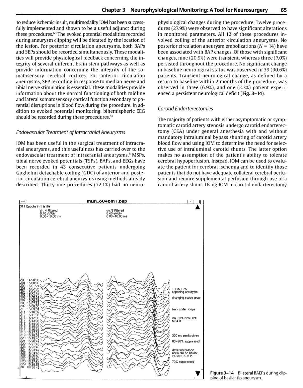
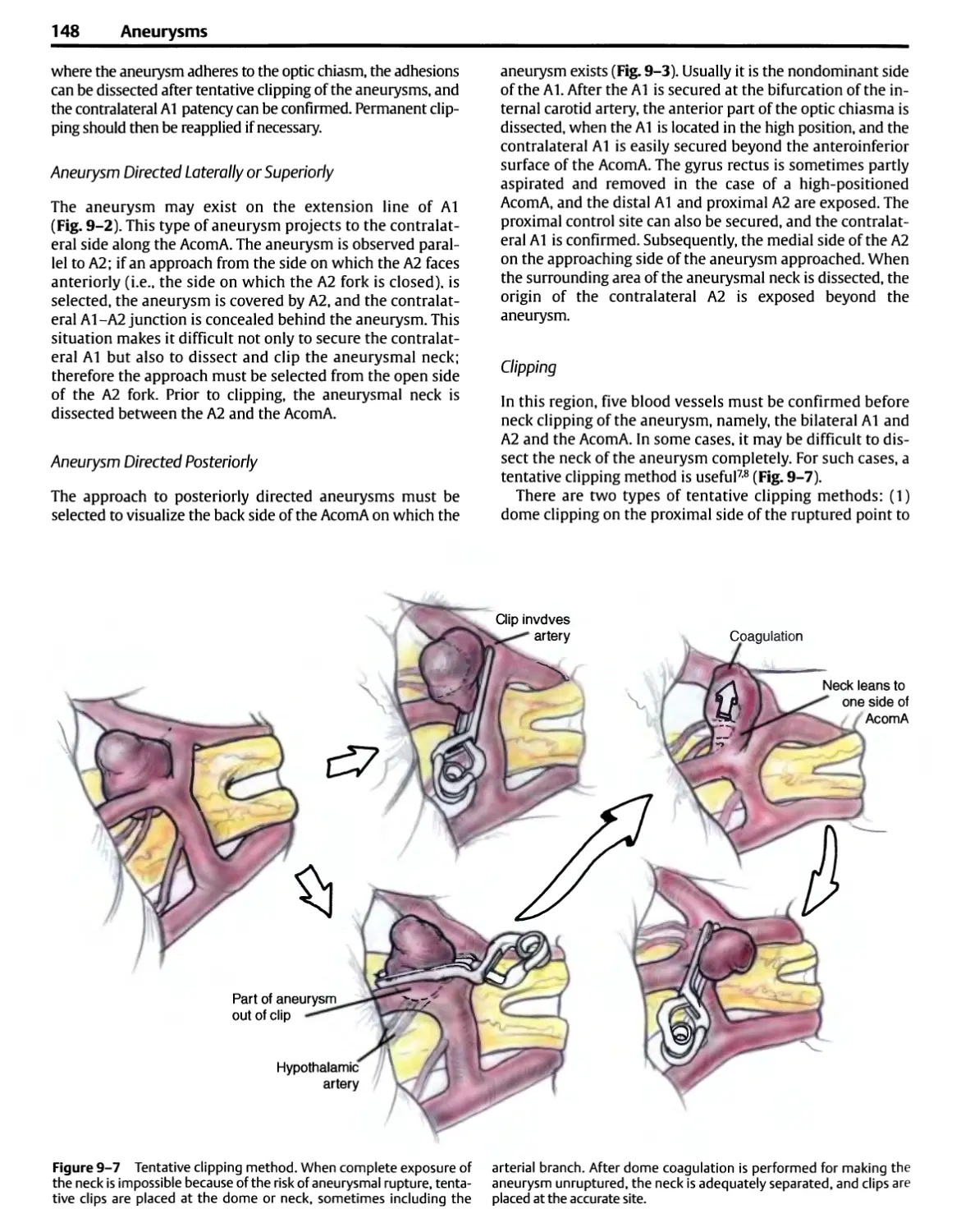
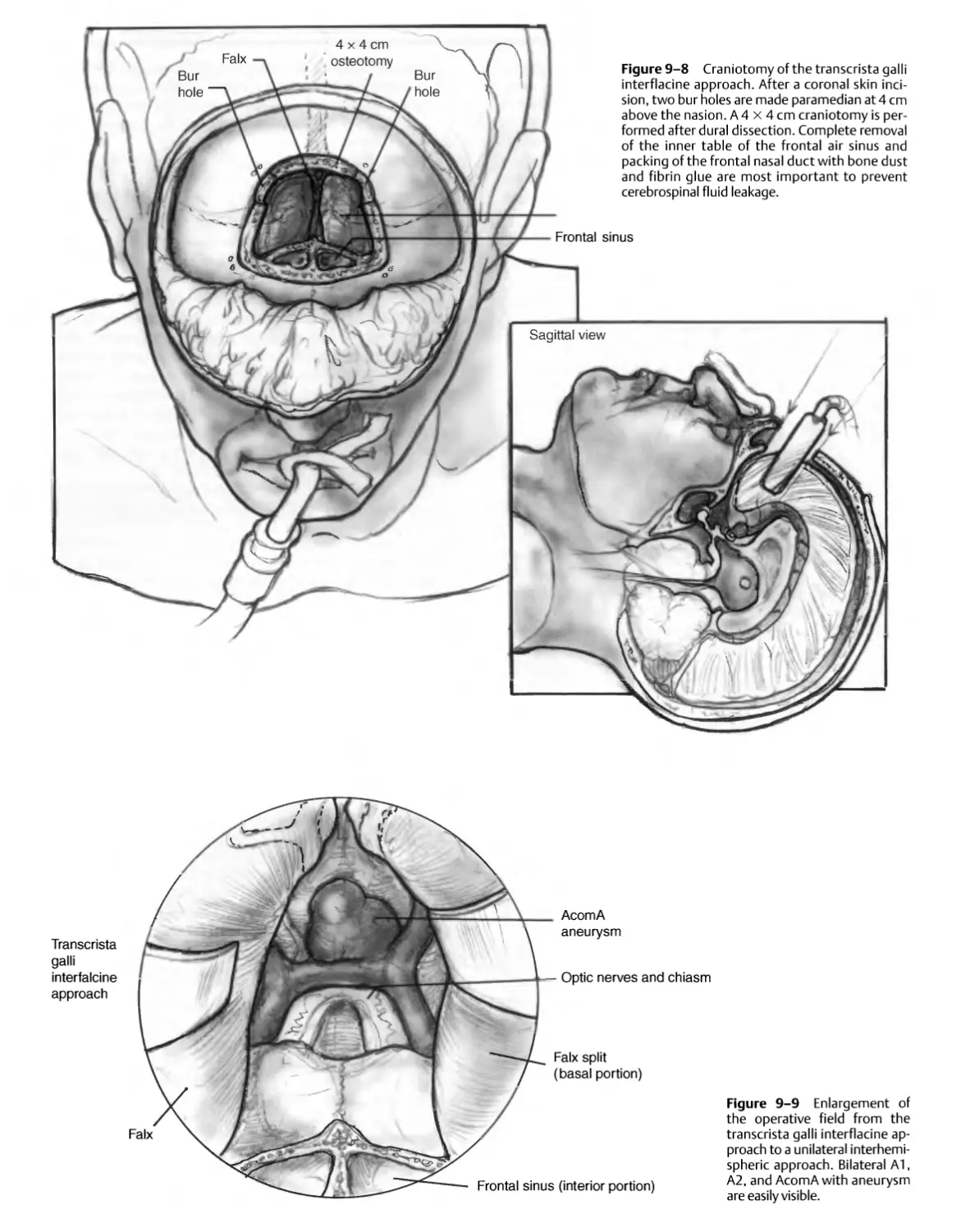
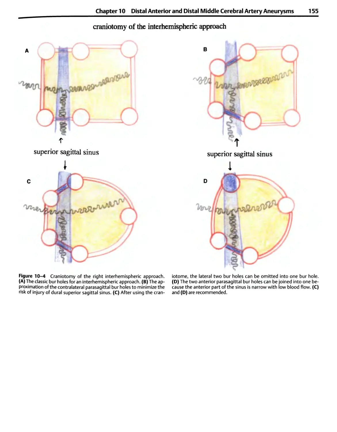
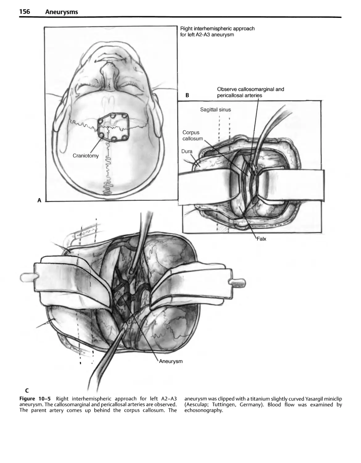
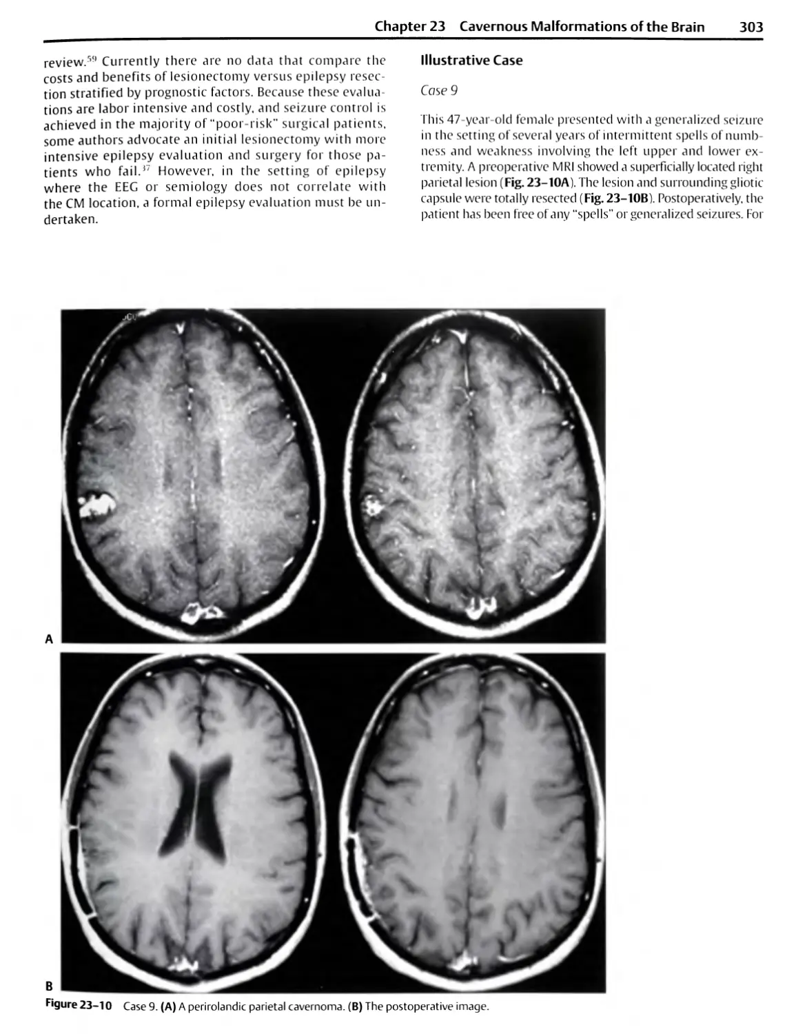
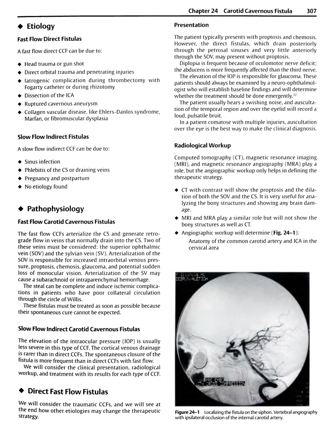
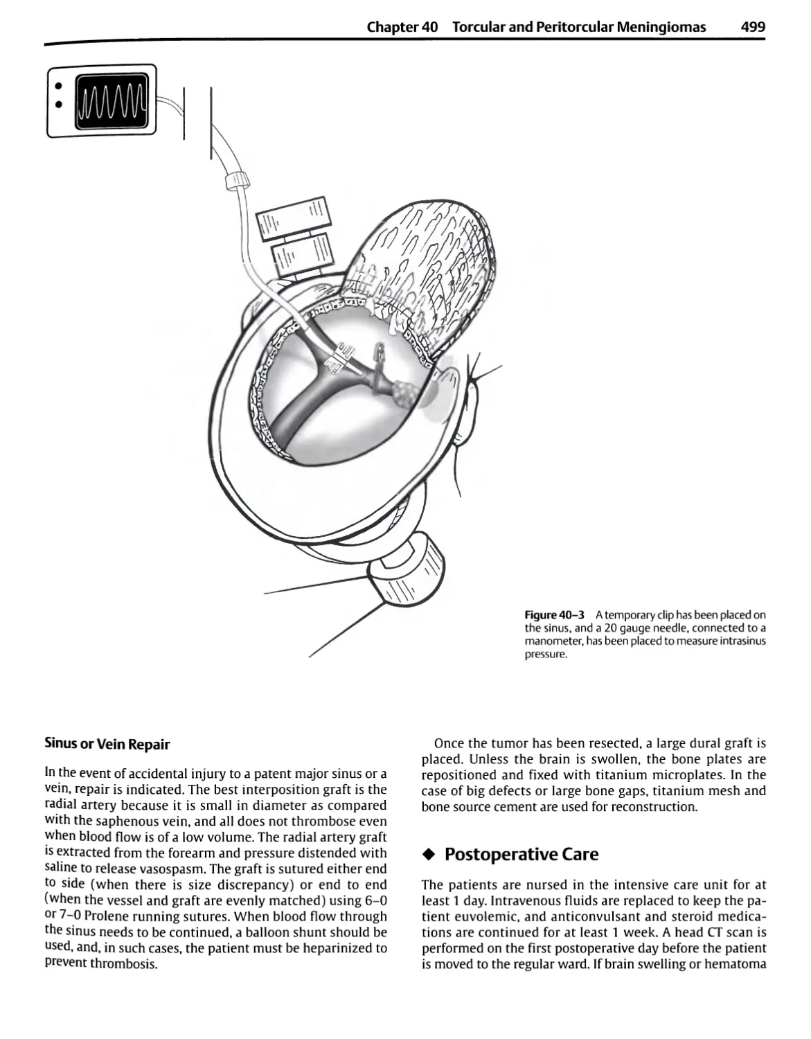
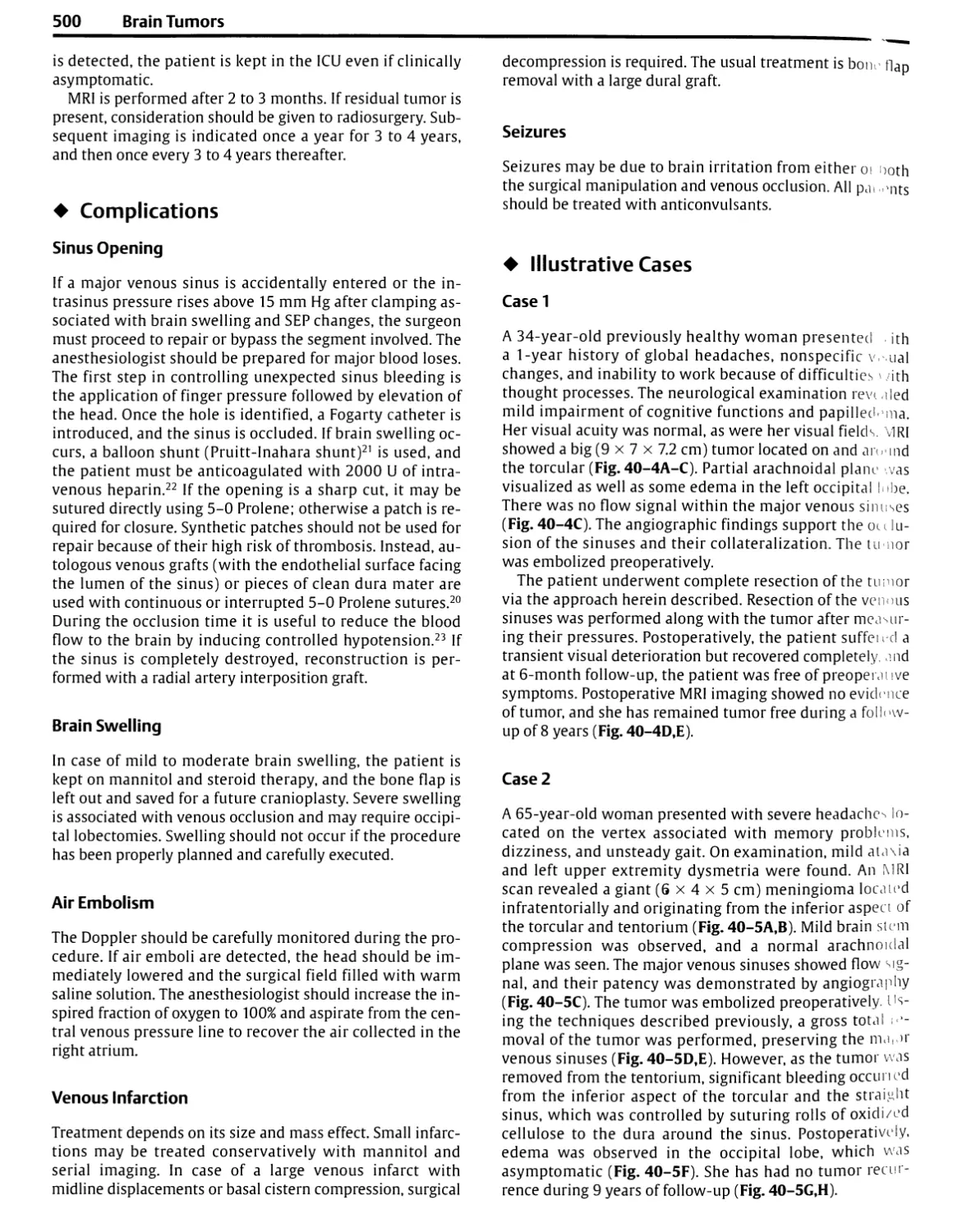
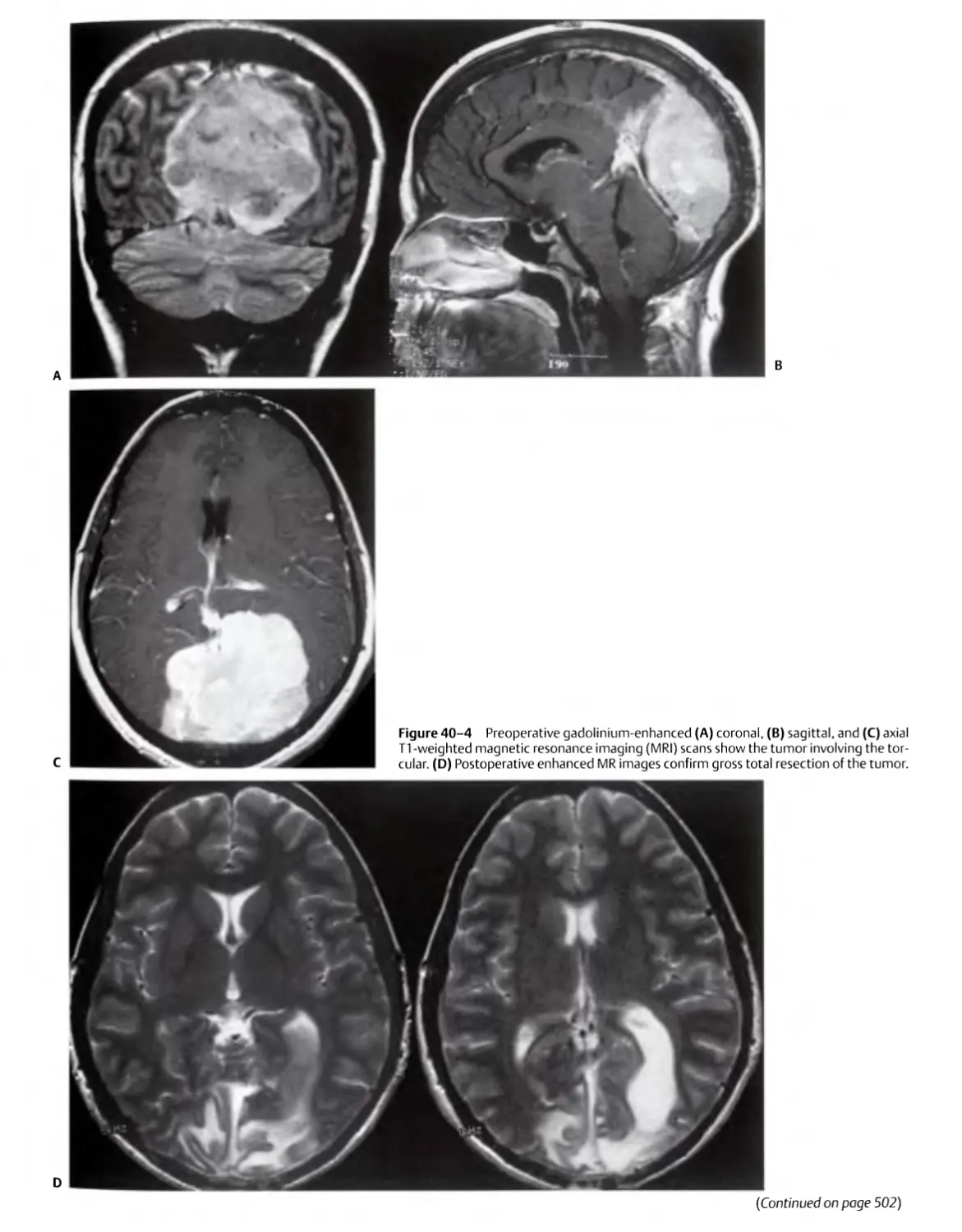
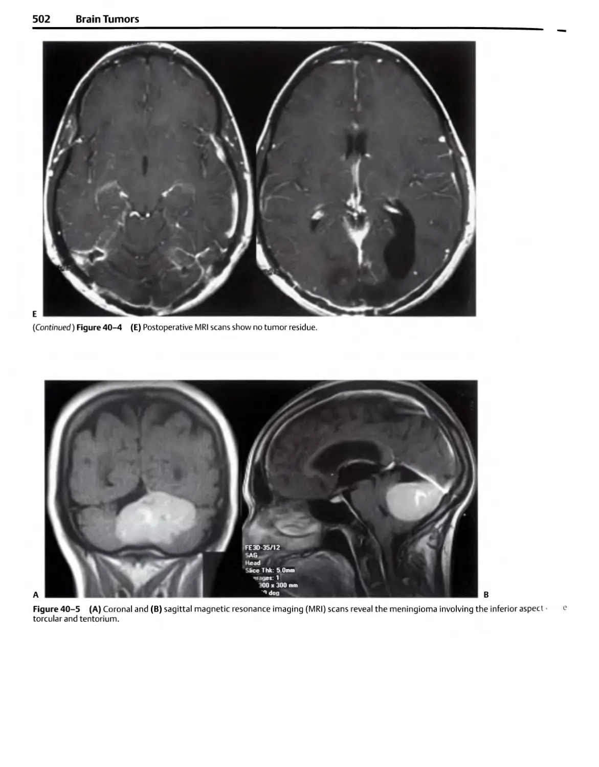
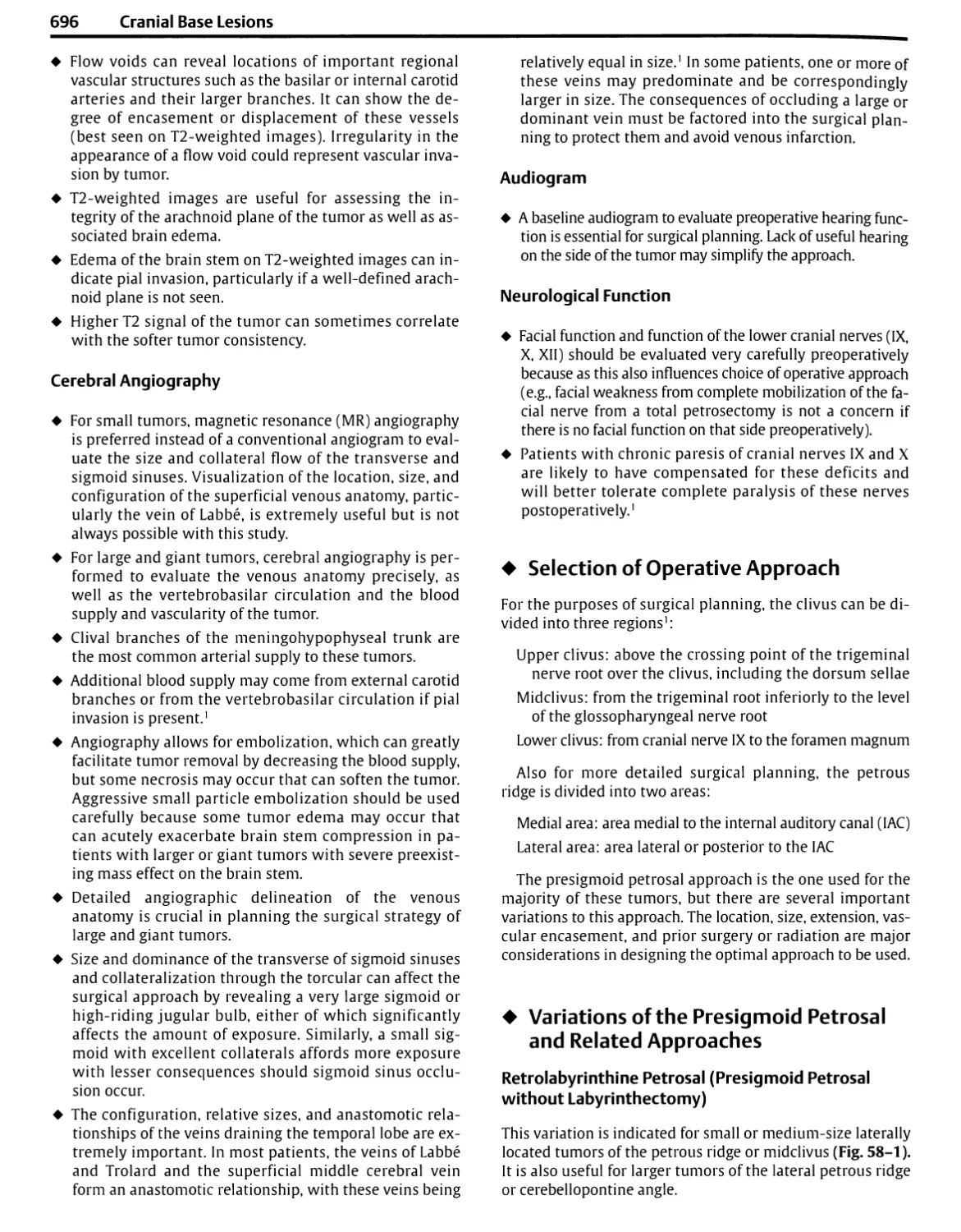
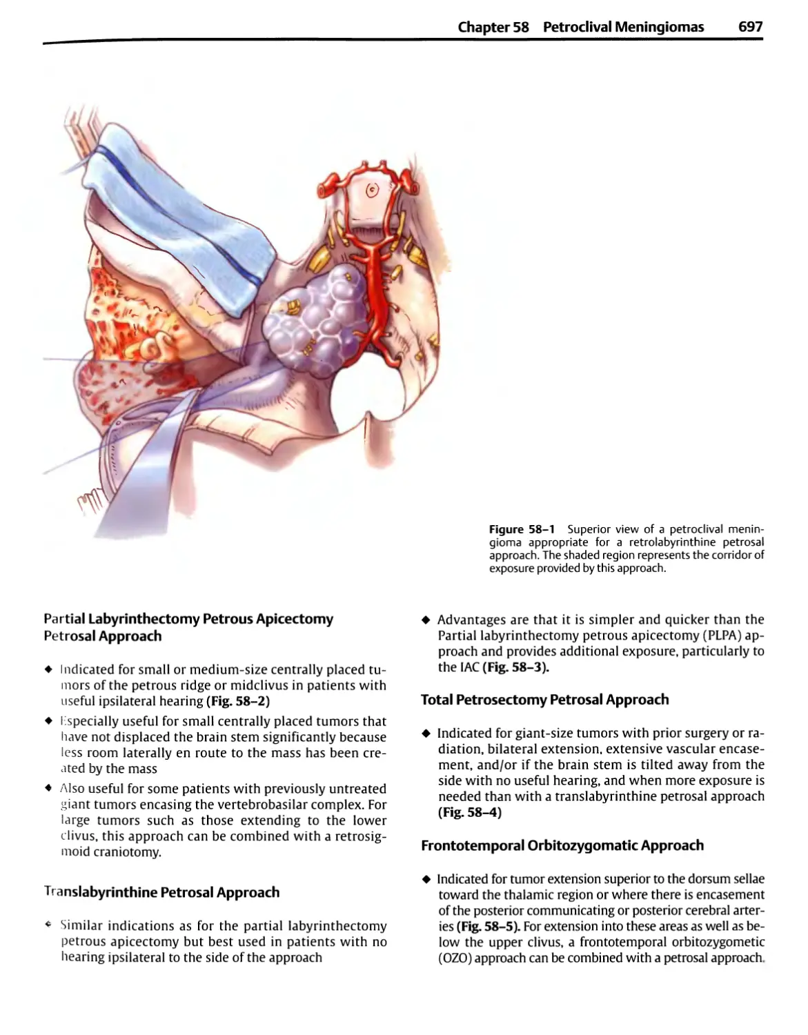
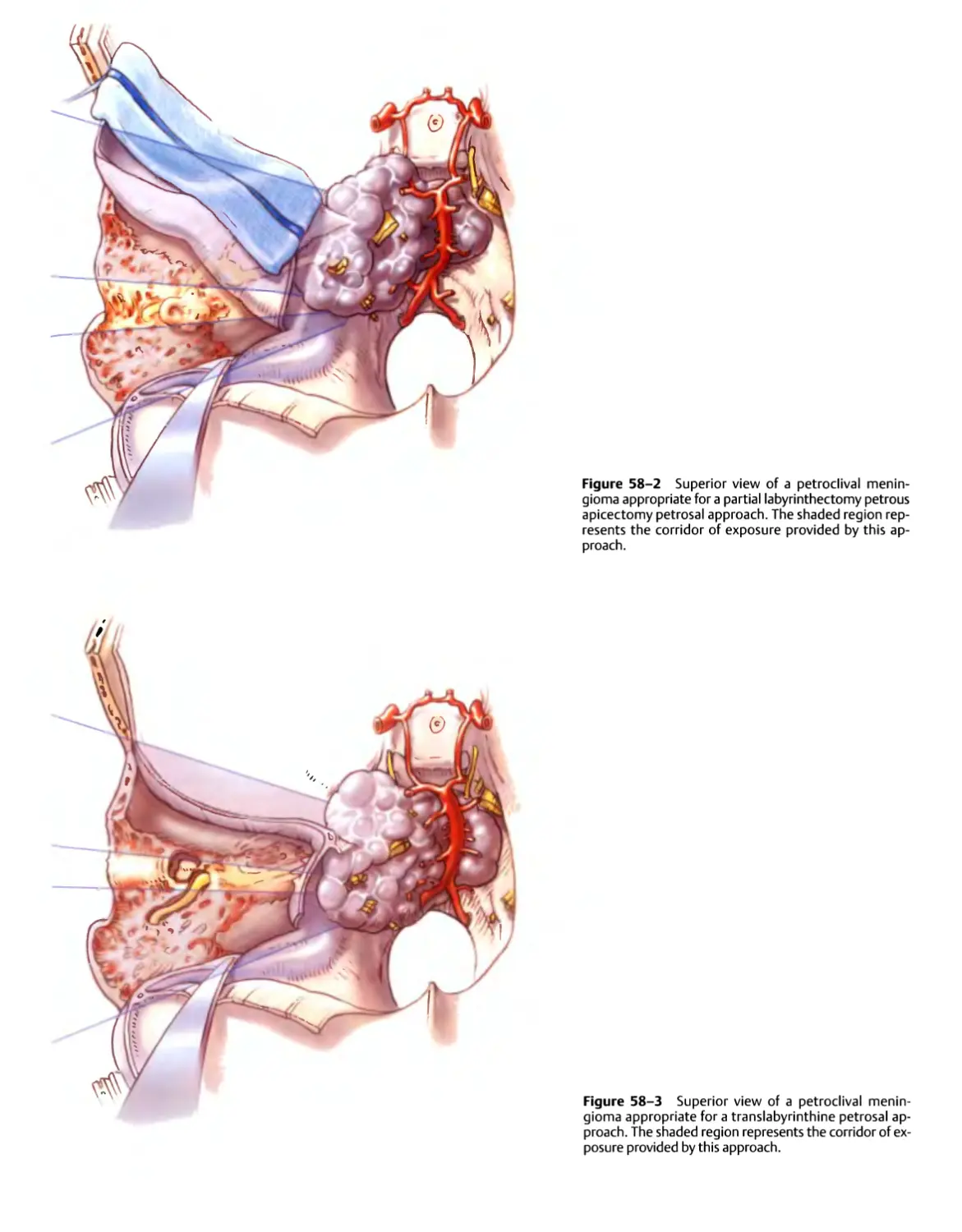
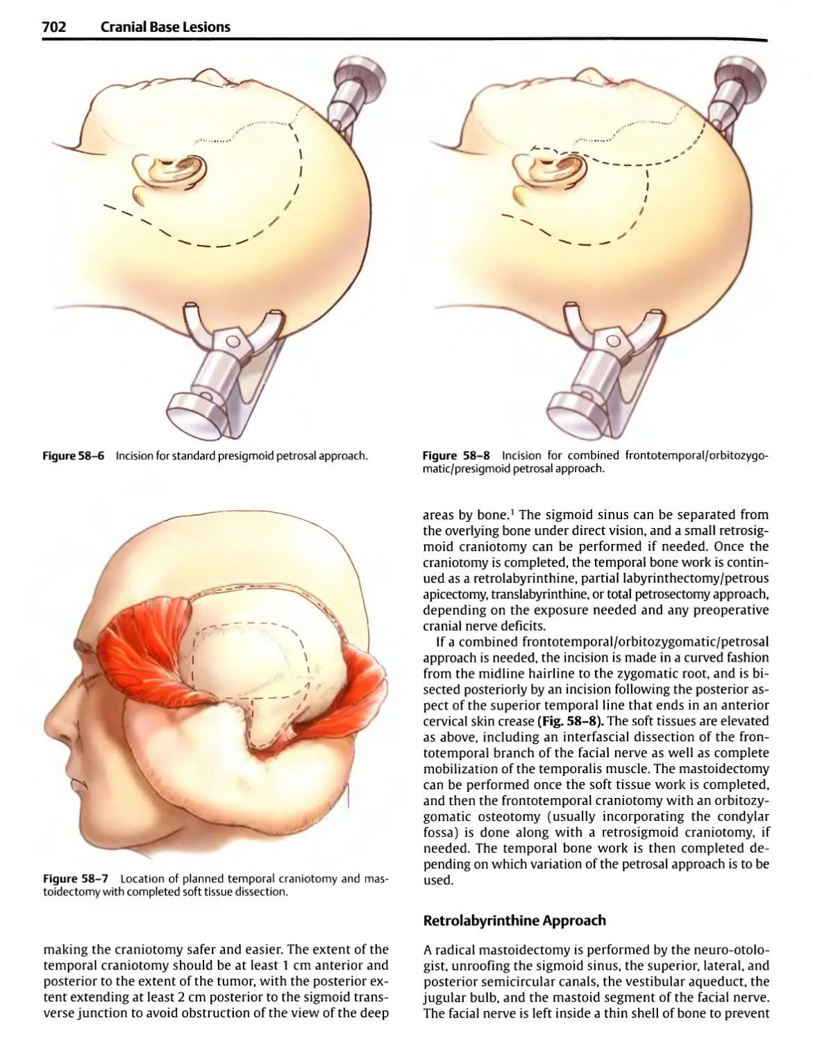
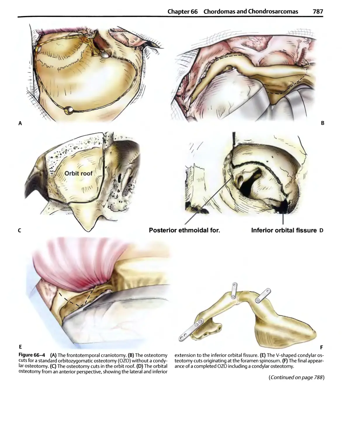
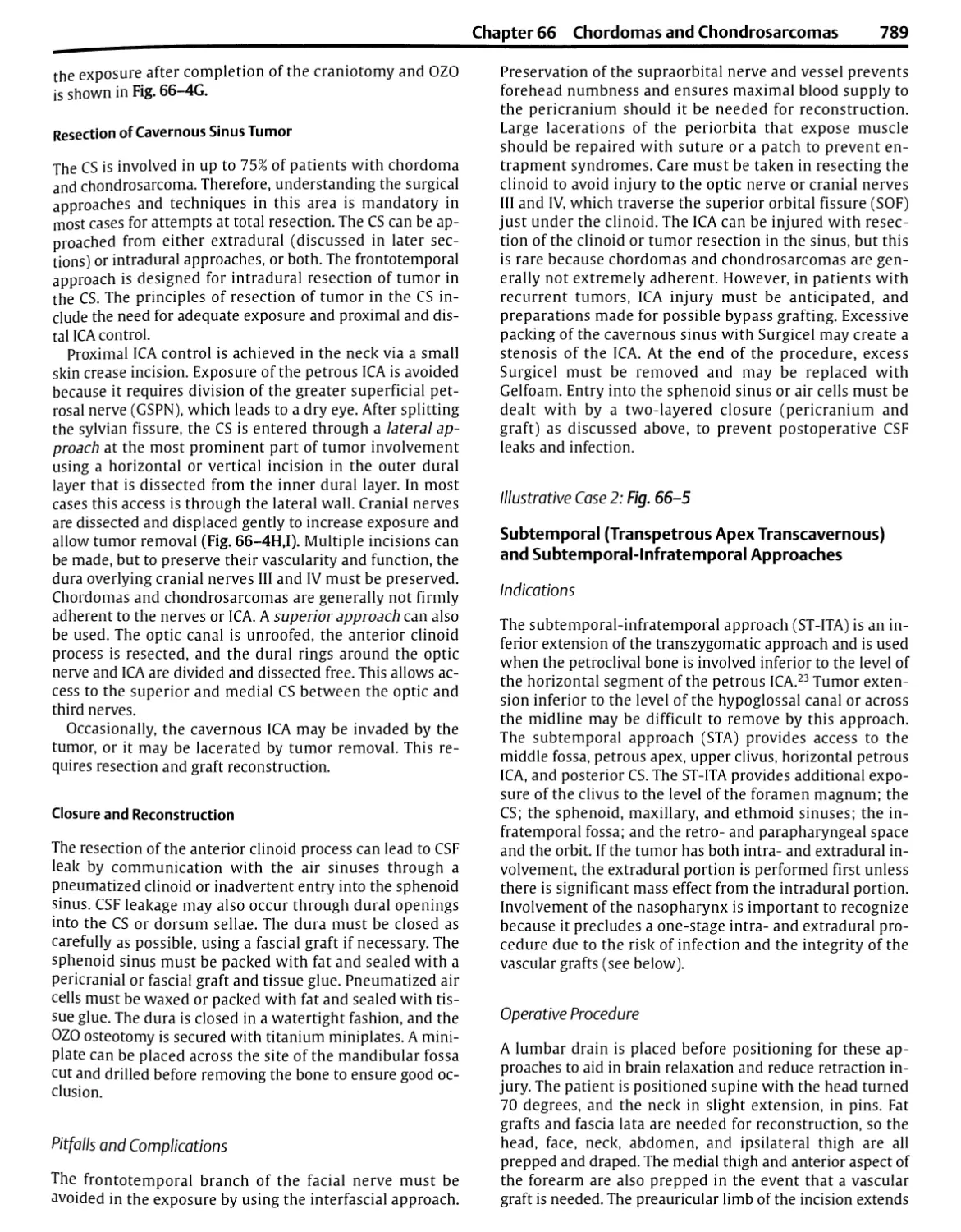
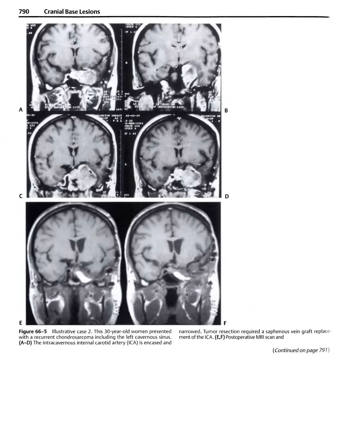
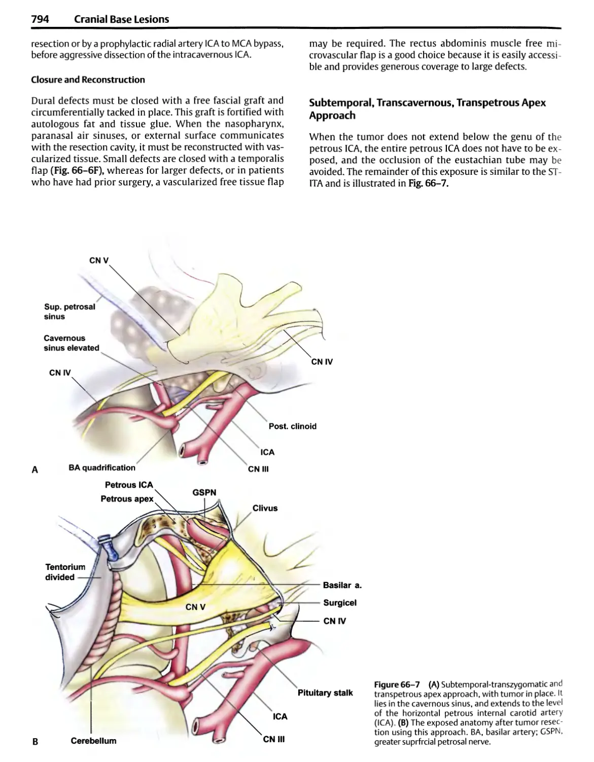
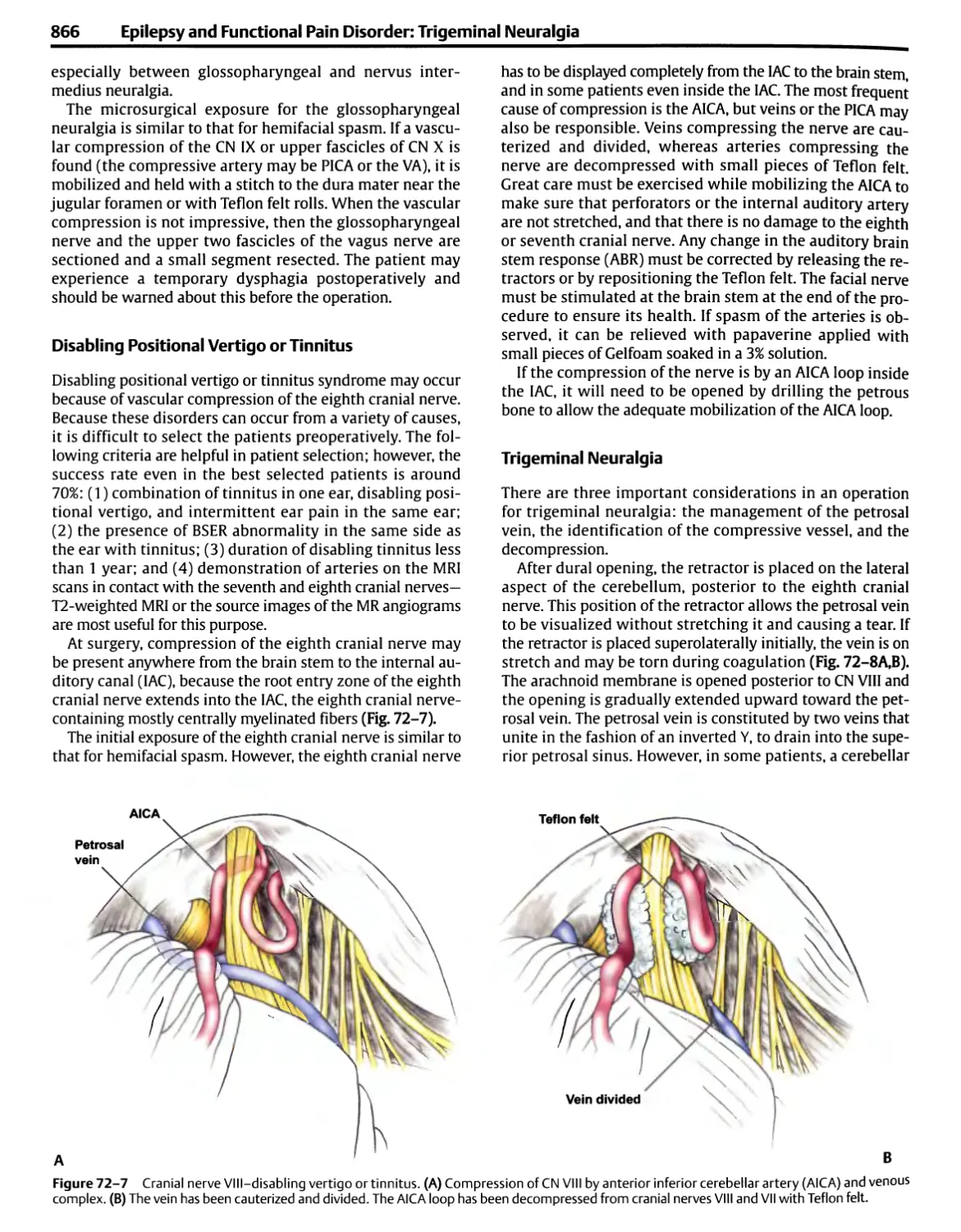
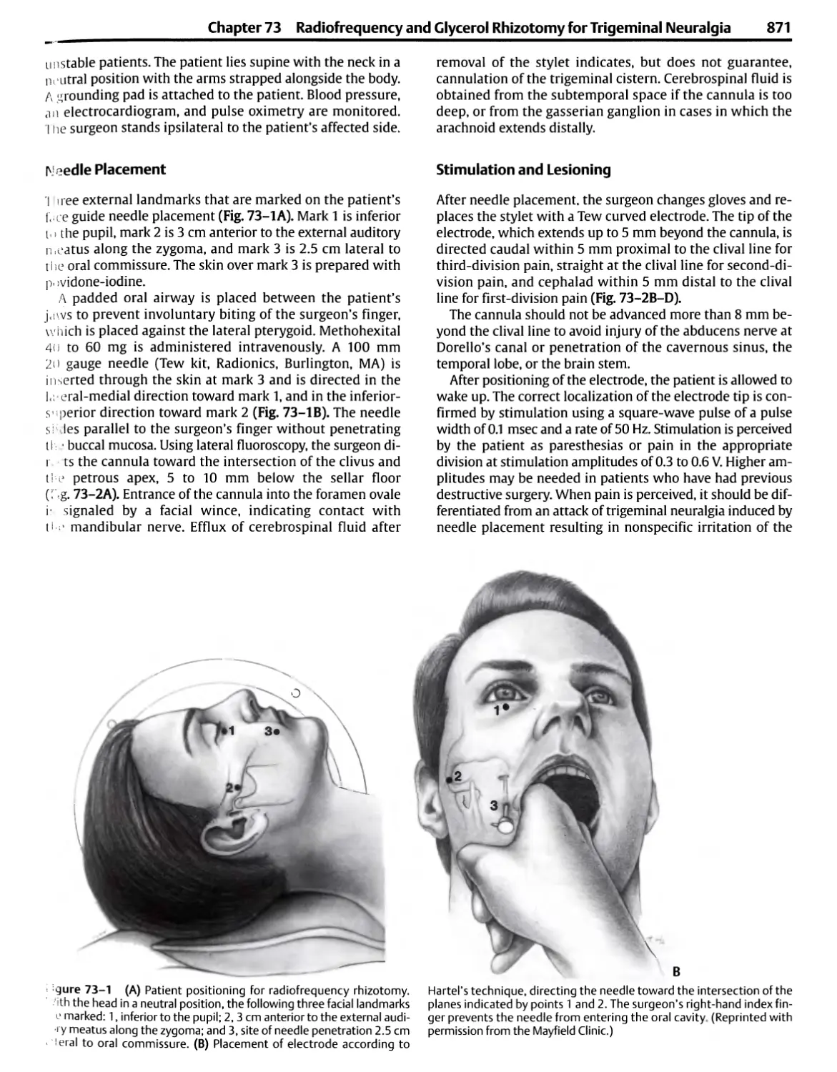
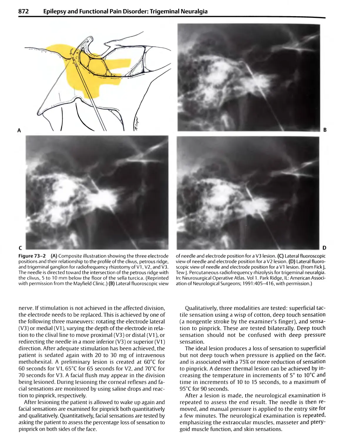
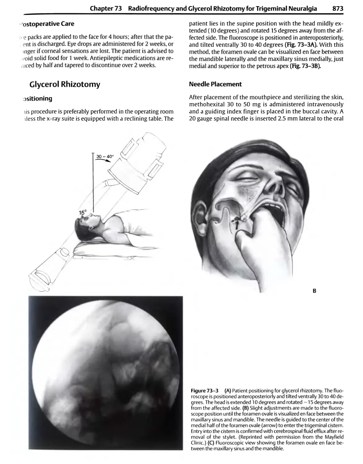
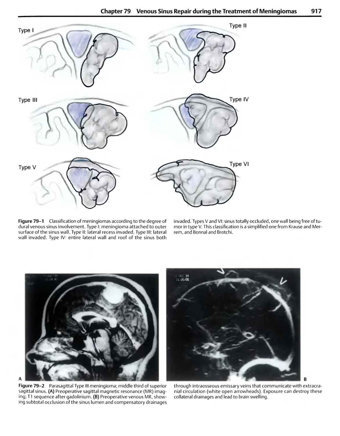
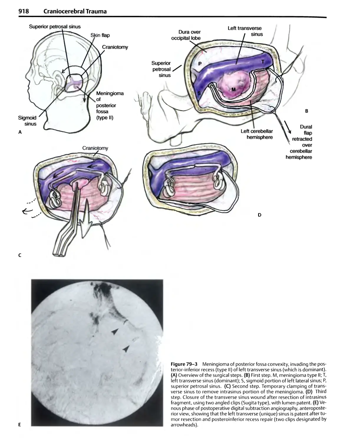
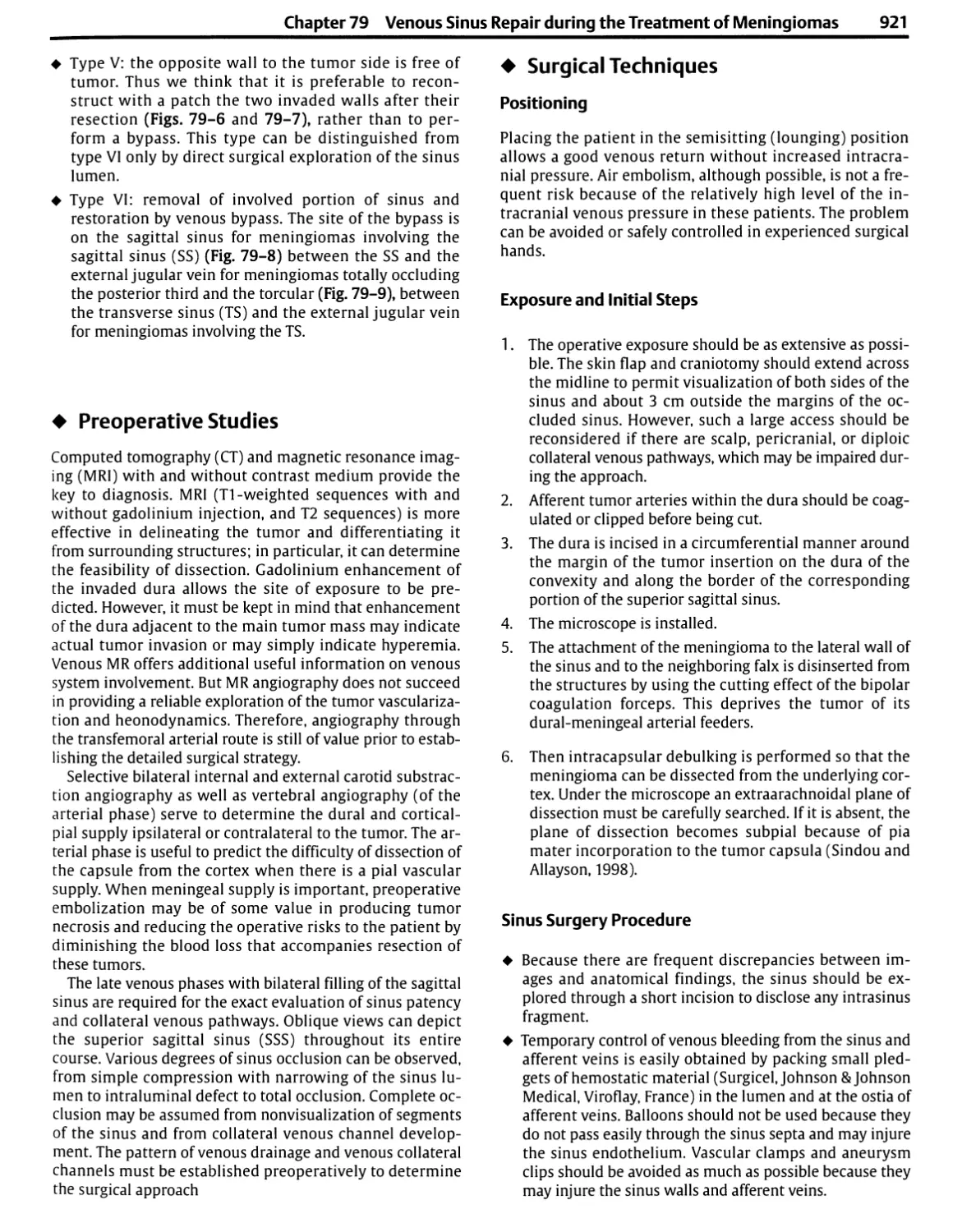
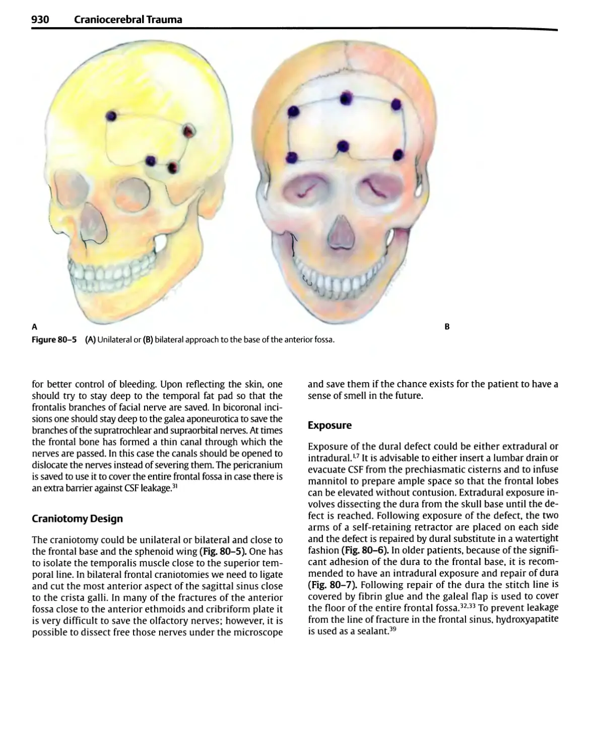
/


Автор: Sekhar Laligam N. Fessler Richard G.
Теги: medicine atlas neurosurgery
ISBN: 9783131275417
Год: 2006


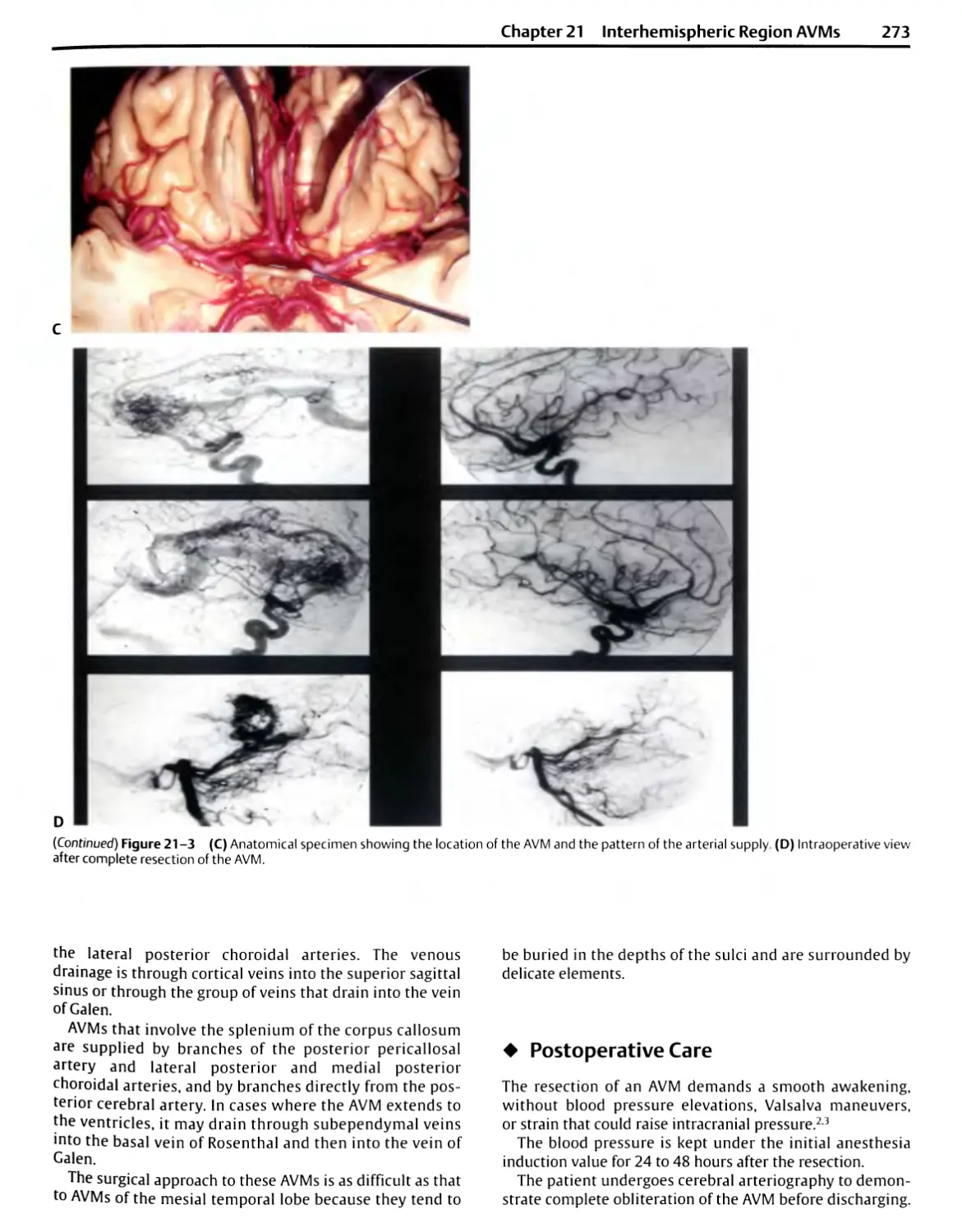
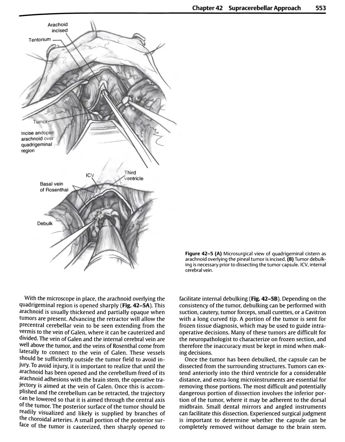
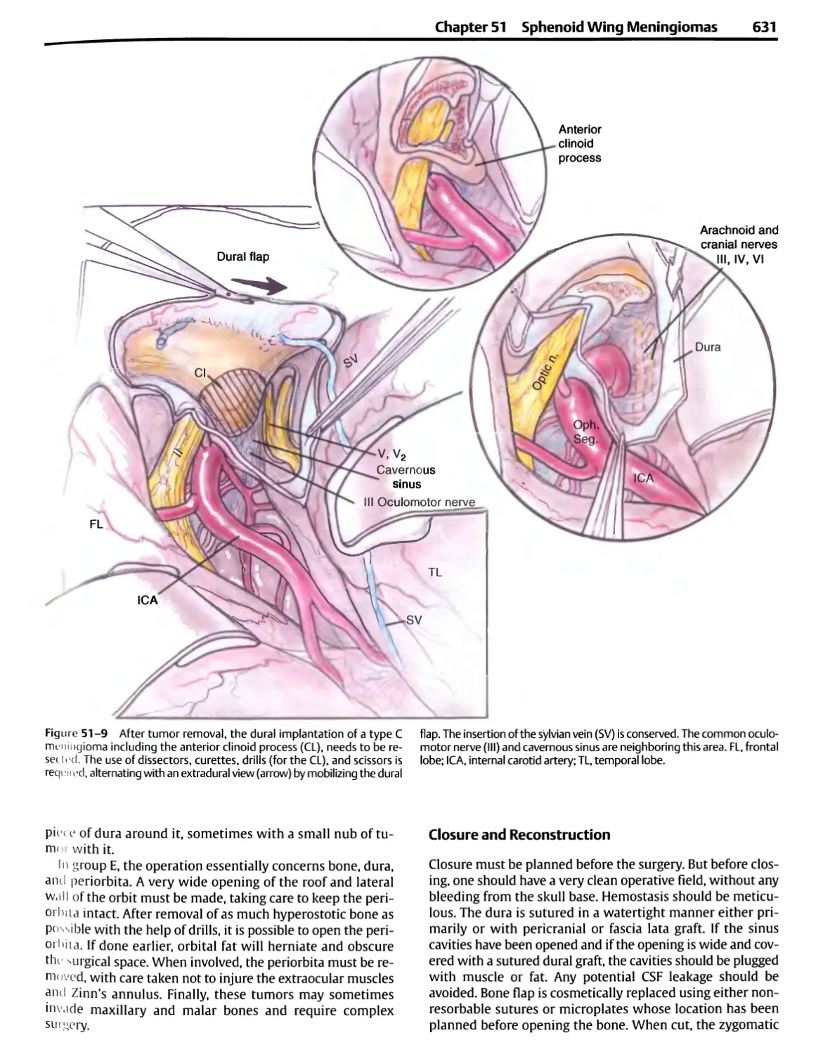
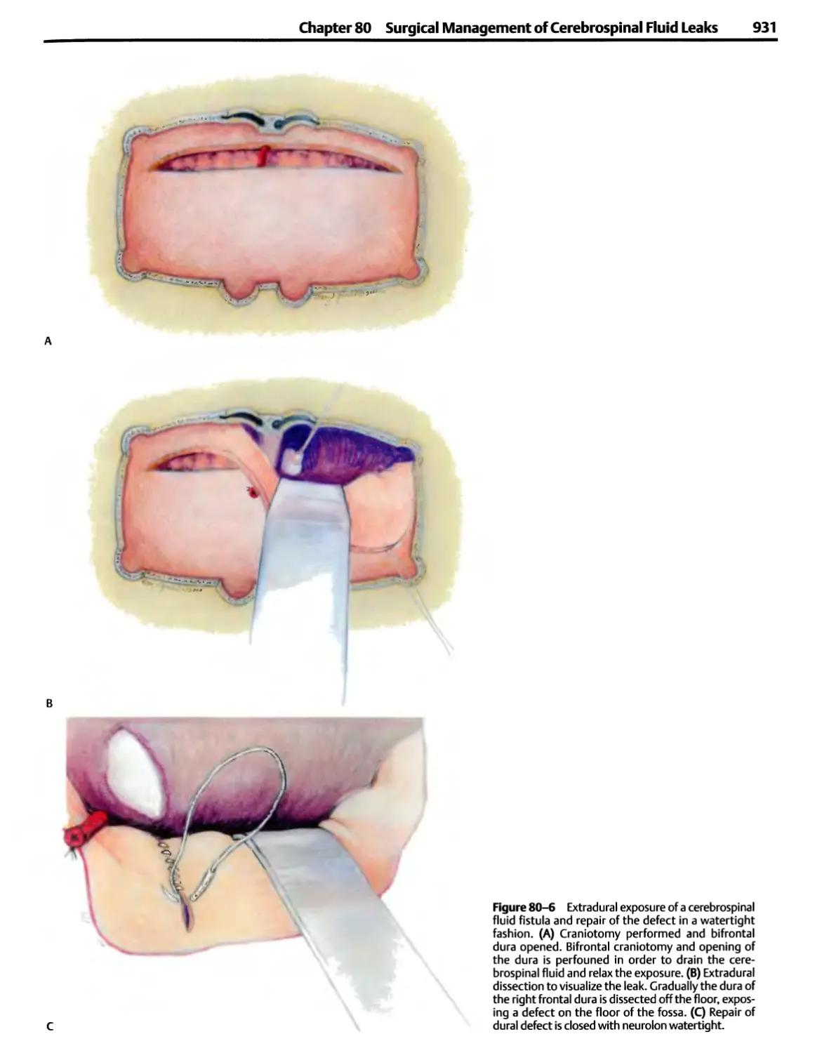
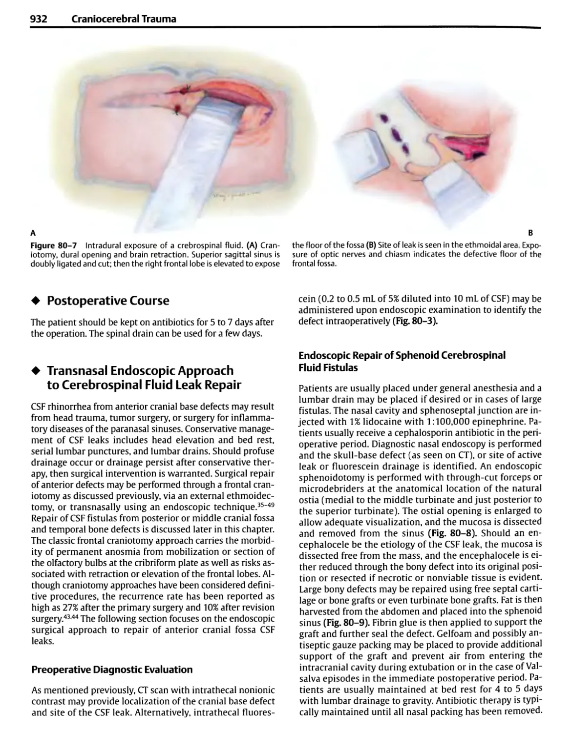
Текст
Atlas of Neurosurgical Techniques
Brain
Laligam N. Sekhar, M.D., F.A.C.S.
Professor and Vice Chairman
Department of Neurological Surgery
University of Washington
Director, Cerebrovascular Surgery
Co-Director, Skull Base Surgery
Harborview Medical Center
Seattle, Washington
Richard G. Fessler, M.D., Ph.D.
John Harper Seeley Professor and Chief
Section of Neurosurgery
Department of Surgery
The University of Chicago Hospitals
Chicago, Illinois
Thieme
New York • Stuttgart
Section I
Introduction
¦ 1. General Principles of and
Instrumentation for Cranial
Surgery
¦ 2. Anesthesia Techniques for Cranial
Base Surgery
¦ 3. Neurophysiological Monitoring:
A Tool for Neurosurgery
¦ 4. Postoperative Critical Care for
Neurosurgery
1
General Principles of and Instrumentation
for Cranial Surgery
Albert L Rhotonjr.
¦ General Considerations
Head Fixation Devices
¦ Instrument Selection
Bayonet Forceps
Bipolar Coagulation
Scissors
Dissectors
Needles, Sutures, and Needle Holders
Suction Tubes
Brain Retractors
Drills
Bone Curettes
Cup Forceps
¦ Operating Microscope
¦ Ultrasonic and Laser Dissection
Ultrasonic aspirators
Laser Microsurgery
The introduction of the operating microscope in
neurosurgery brought about the greatest improvement in
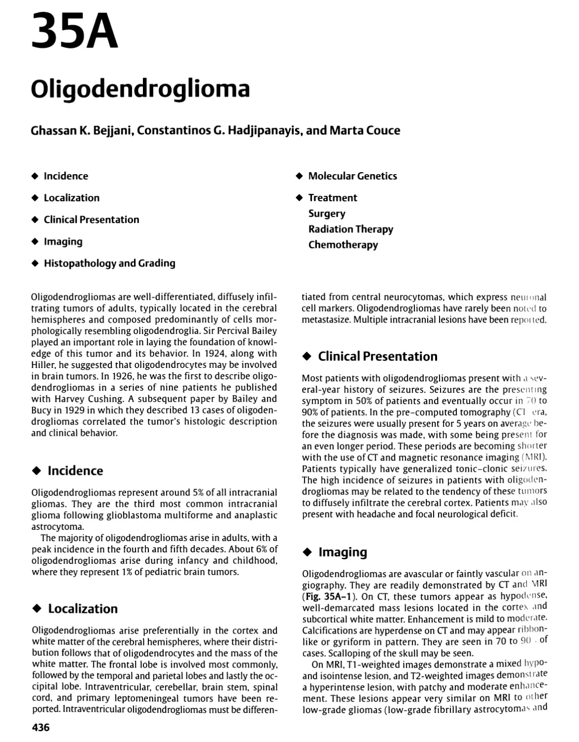
operative techniques that has occurred in the history of the
specialty. The microscope has resulted in profound changes
in the selection and use of instruments and in the way
neurosurgical operations are completed. The advantages
provided by the operating microscope in neurosurgery
were first demonstrated during the removal of acoustic
neuromas.1 The benefits of magnified stereoscopic vision
and intense illumination provided by the microscope were
quickly realized in other neurosurgical procedures. The
operating microscope is now used for the intradural portion
of nearly all operations on the head and spine and for most
extradural operations along the spine and skull base,
converting almost all of neurosurgery into micro-operative
specialty.2
Microsurgery has improved the technical performance of
many standard neurosurgical procedures (e.g., brain tumor
removal, aneurysm obliteration, neurorrhaphy, lumbar and
cervical diskectomy) and has opened new dimensions
previously unattainable to the neurosurgeon. It has improved
operative results by permitting neural and vascular
structures to be delineated with greater visual accuracy, deep
areas to be reached with less brain retraction and smaller
cortical incisions, bleeding points to be coagulated with
less damage to adjacent neural structures, nerves distorted
by tumor to be preserved with greater frequency, and
anastomosis and suture of small vessels and nerves not
previously possible. Its use has resulted in smaller wounds, less
postoperative neural and vascular damage, better hemosta-
sis, more accurate nerve and vascular repairs, and
operations for some previously inoperable lesions. It has
introduced a new era in surgical education by permitting the
observation and recording, for later study and discussion,
of minute operative detail not visible to the naked eye.
Some general considerations are reviewed prior to the
discussion of instrument selection and operative techniques.
¦ General Considerations
Achieving a satisfactory operative result depends not only on
the surgeon's technical skill and dexterity but also on a host
of details related to accurate diagnosis and careful operative
planning. Essential to this plan is having a patient and family
members who are well informed about the operation and
understand the side effects and risks. The surgeon's most
important ally is a well-informed patient.
Scheduling in the operating room should include
information about the side and site of the pathology and the
position of the patient so that the instruments and
equipment can be positioned properly before the patient arrives
(Fig. 1-1). Any unusual equipment needs should be listed at
the time of scheduling. There are definite advantages to
operating rooms dedicated to neurosurgery and to having a
team of nursing personnel who know the equipment and
procedures for neurosurgical cases.
Before induction, the surgeon and anesthesiologist should
reach an understanding regarding the need for steroids,
hyperosmotic agents, anticonvulsants, antibiotics,
barbiturates, and lumbar and ventricular drainage, and intraoperative
3
4 Introduction
evoked potential, electroencephalogram, or other
specialized monitoring. Elastic or pneumatic stockings are placed
on the patient's lower extremities to prevent venous
stagnation and postoperative phlebitis and emboli. A urinary
catheter is inserted if the operation is expected to last more
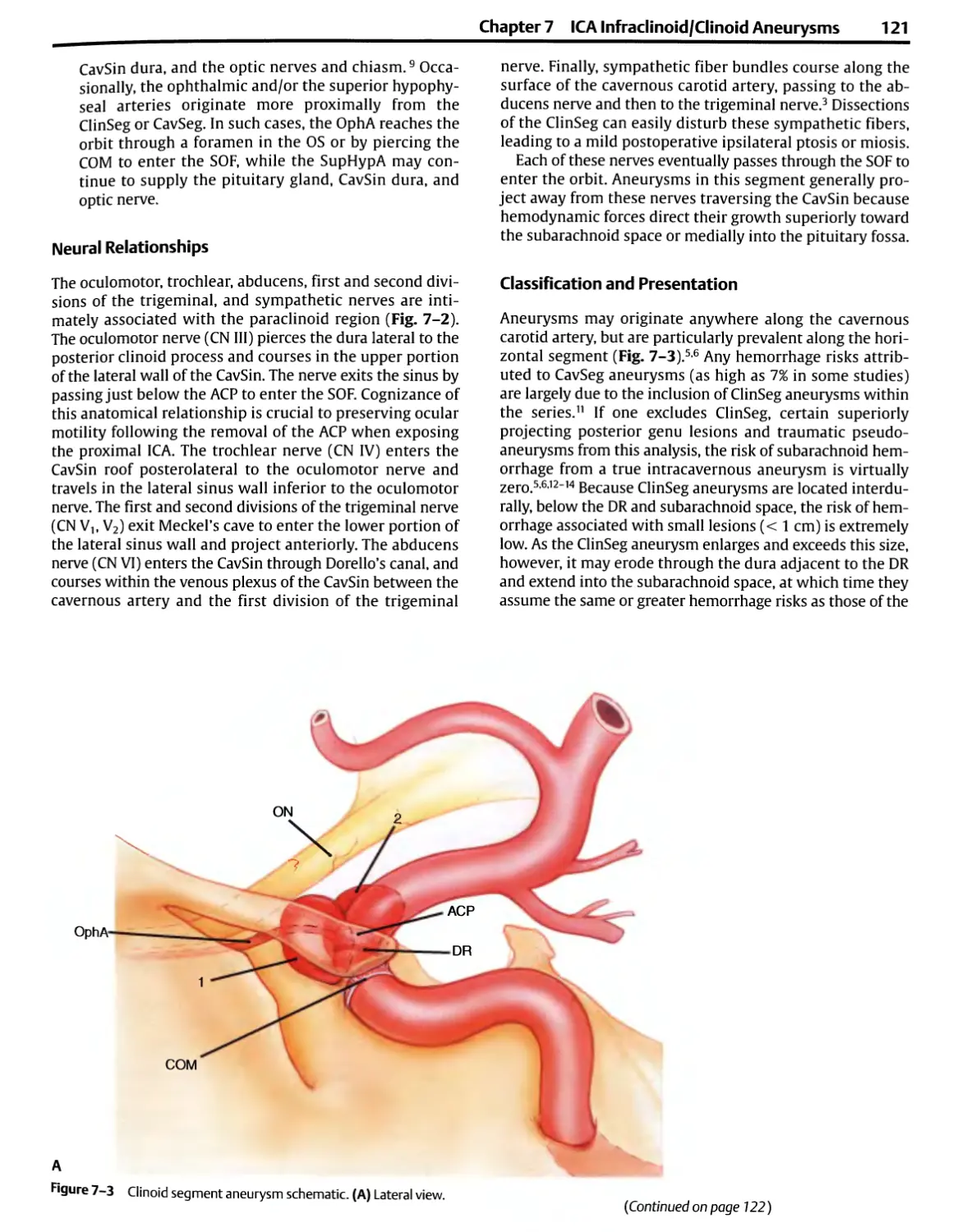
than 2 hours. If the patient is positioned so that the
operative site is significantly higher than the right atrium, a
Doppler monitor is attached to the chest or inserted in the
esophagus, and a venous catheter is passed into the right
atrium so that venous air emboli may be detected and
treated. At least two intravenous lines are established if
significant bleeding is likely to occur.
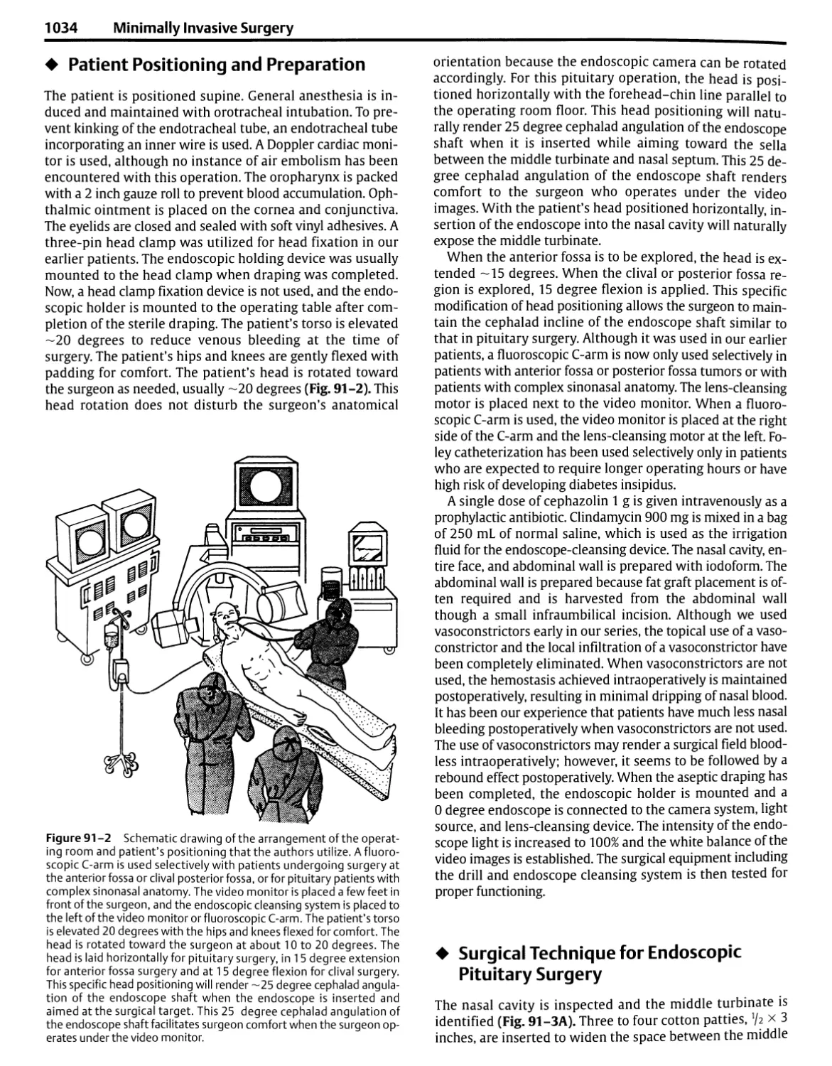
Most intracranial procedures are done with the patient in
the supine, three-quarter prone (lateral oblique or park
bench), or full prone position, with the surgeon sitting at
the head of the table (Figs. 1-1A-C). The supine position,
with appropriate turning of the patient's head and neck and
possibly elevating one shoulder to rotate the upper torso, is
Radiographic View
Sur9eon „ Assistant
Microscope on Floor Stand
Solution Basin
Basic Table
TV Monitor
Anesthesia Machine
Anesthesia Cart
Image Guidance
Monitor
Air Drill Gas Tank
Mono- and Bipolar
Electrosurgical Units
Image Guidance Camera
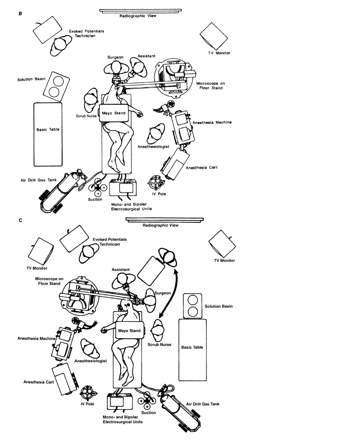
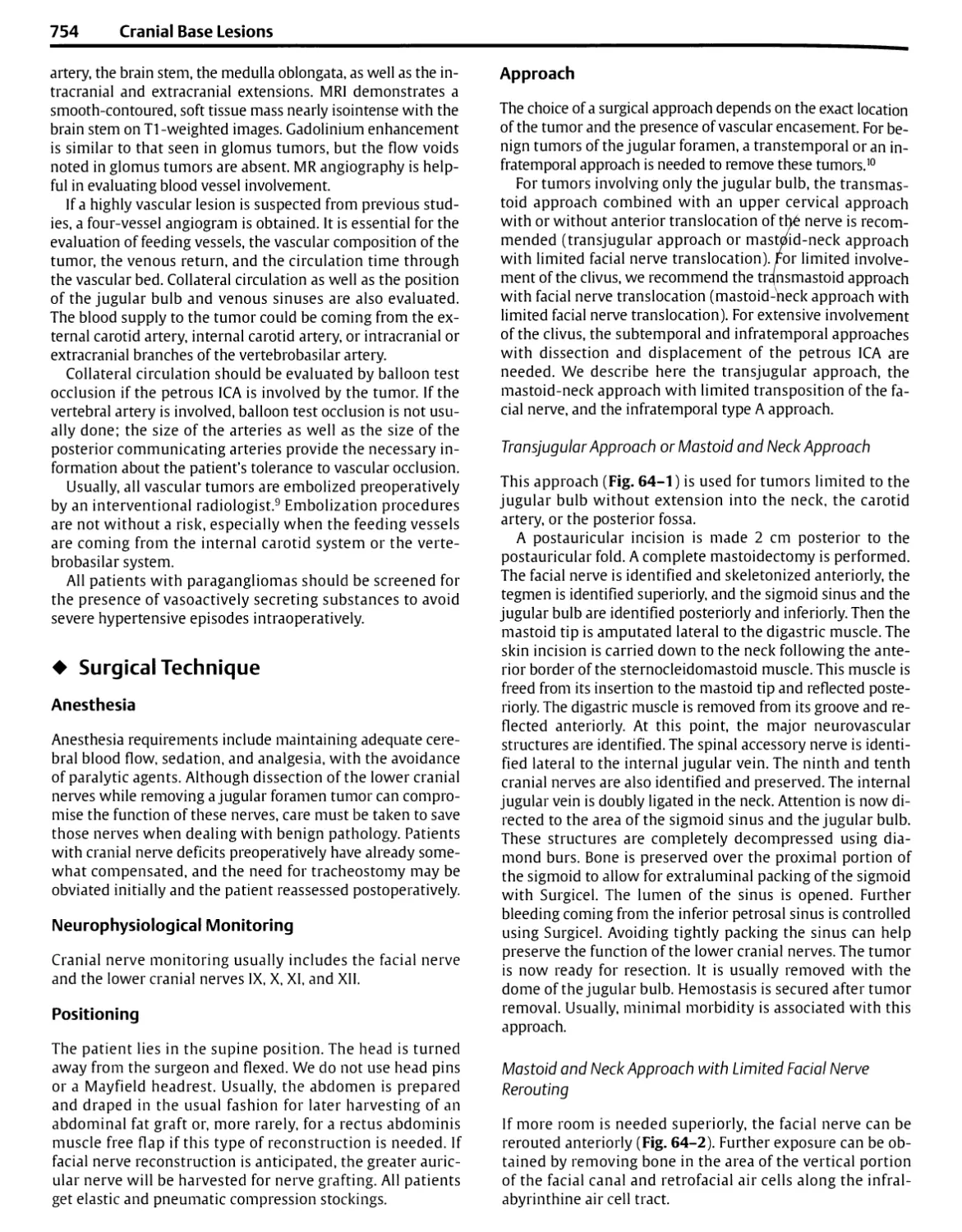
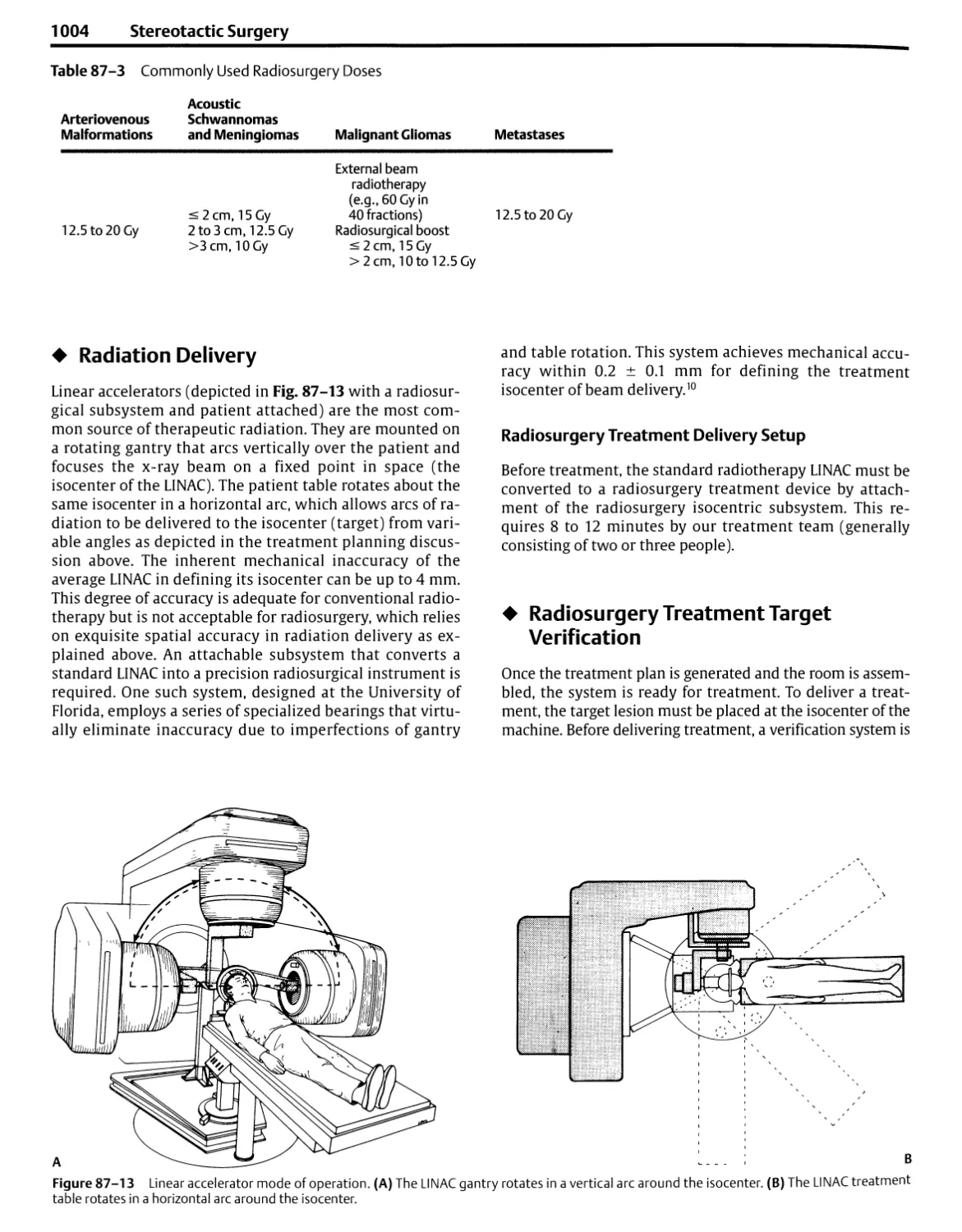
Figure 1 -1 Positioning of staff and equipment in the operating room.
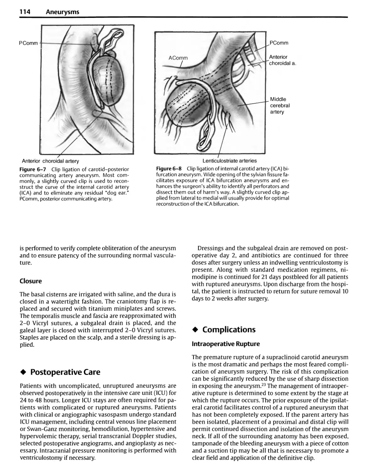
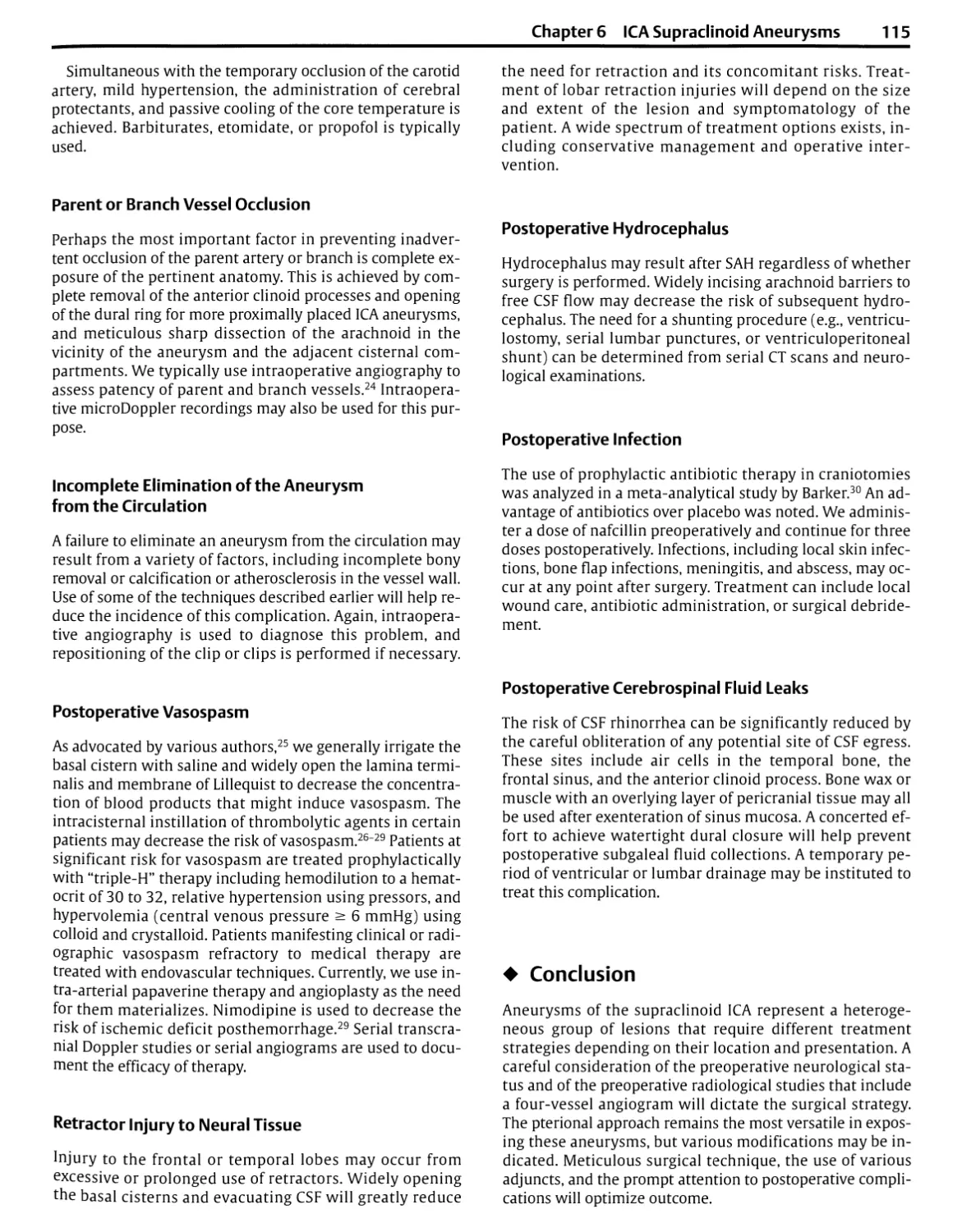
(A) For performing a right frontotemporal craniotomy, the
anesthesiologist is positioned on the patient's left side for easy access to the airway,
monitors on the chest, and the intravenous and intra-arterial lines. The
microscope stand is positioned to the right of the anesthesiologist. The
scrub nurse, positioned on the right side of the patient, passes
instruments to the surgeon's right hand. The position is reversed for a left
frontotemporal craniotomy, placing the anesthesiologist and microscope on
the patient's right side and the nurse on the left side. Mayo stands have
replaced the large, heavy instrument tables that were positioned above
the patient's trunk and restricted access to the patient. The suction,
compressed air for the drill, and electrosurgery units are situated at the
foot of the patient, and the lines from these units are led up near the
Mayo stand so that the nurse can pass them to the surgeon as needed. A
television monitor is positioned so that the nurse can anticipate the
instrument needs of the surgeon. The infrared image guidance camera is
positioned so that the surgeon, assistants, and equipment do not block
the camera's view of the markers at the operative site. (B) Positioning for
a right suboccipital craniotomy directed to the upper part of the
posterior fossa, such as a decompression operation for trigeminal neuralgia.
The surgeon is seated at the head of the patient. The anesthesiologist
and microscope are positioned on the side the patient faces. The
anesthesiologist and nurse shift sides for an operation on the left side.
(C) Positioning for a left suboccipital craniotomy for removal of an
acoustic neuroma. The surgeon is seated behind the head of the patient.
For removal of a left acoustic tumor, the scrub nurse and Mayo stand may
move up to the shaded area, where instruments can be passed to the
surgeon's right hand. For right suboccipital operations or for a midline
exposure, the position is reversed, with the scrub nurse and Mayo stand
positioned above the body of the patient, allowing the nurse to pass
instruments to the surgeon's right hand. In each case, the
anesthesiologist is positioned on the side toward which the patient faces.
(Continued on pages 5 and 6)
6 Introduction
Fluoroscopic View
Radiographic View
Solution Basin
Basic Table
Microscope on Floor Stand
TV Monitor
Anesthesia Machine
Anesthesia Cart
Suction Mono-and Bipolar
Electrosurgicai Units
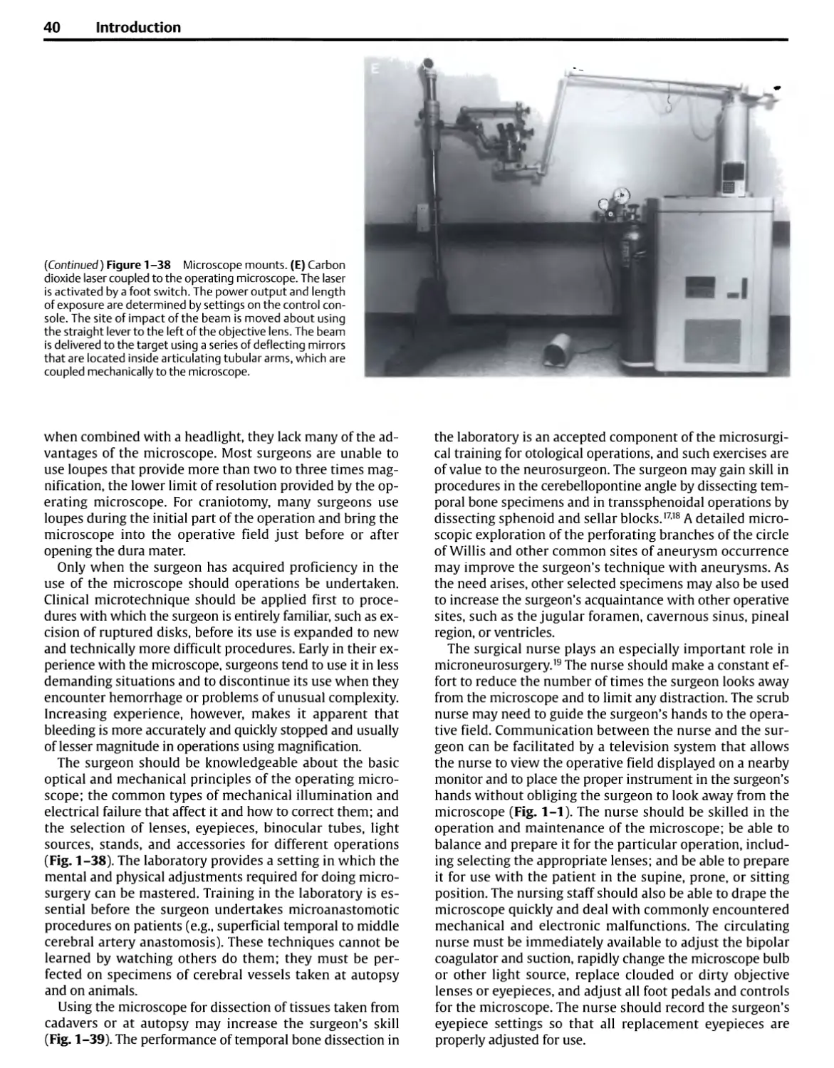
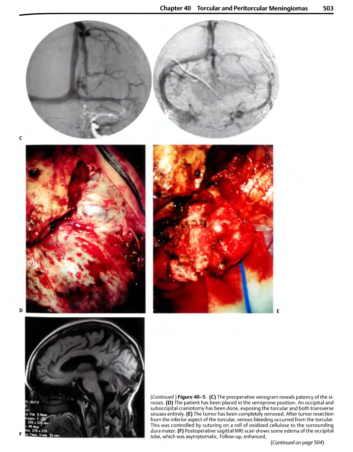
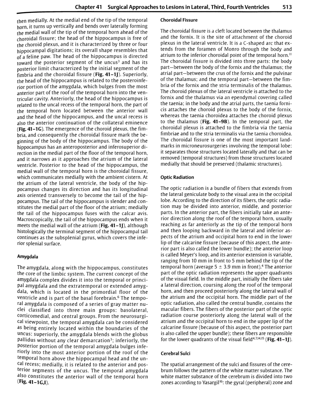
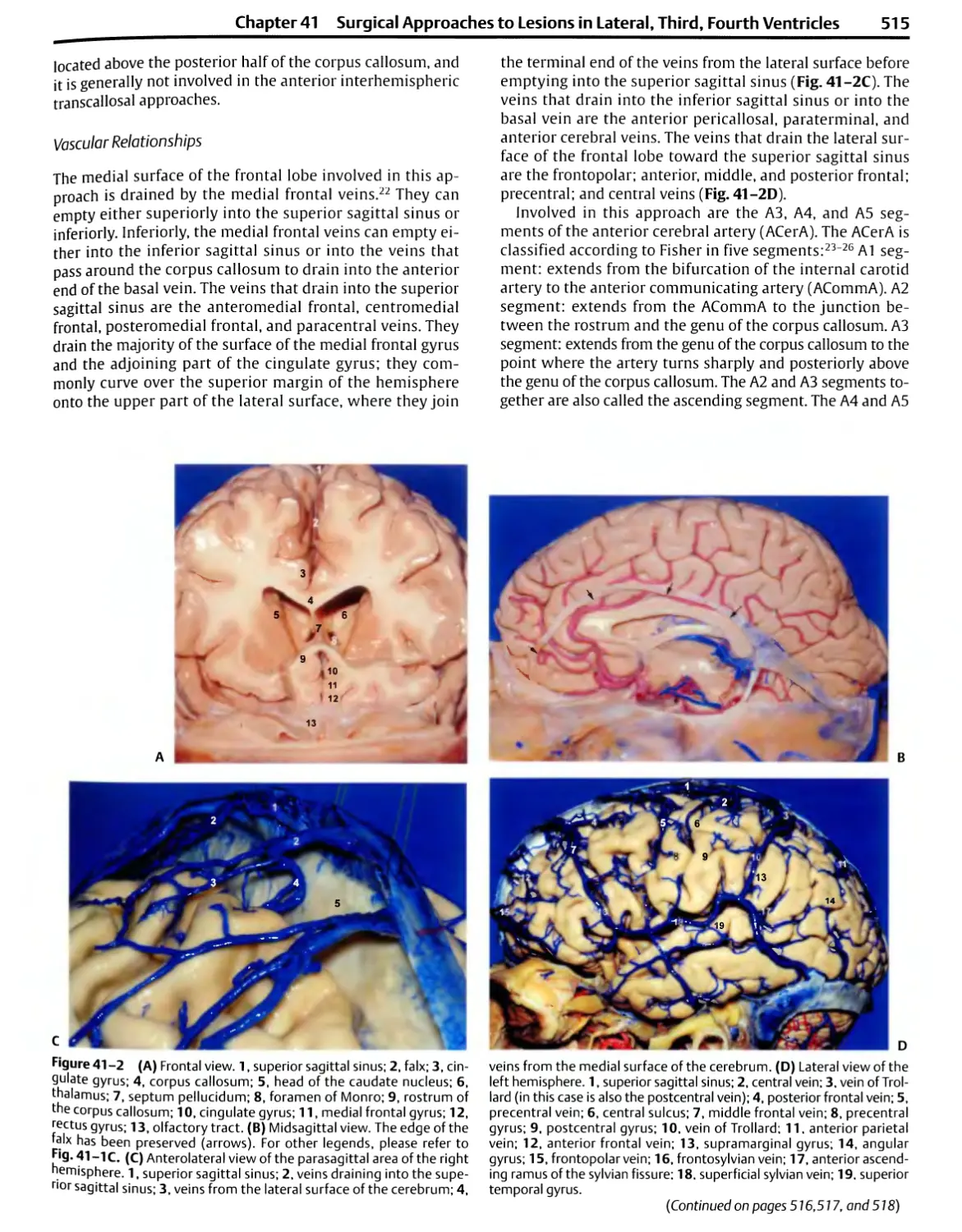
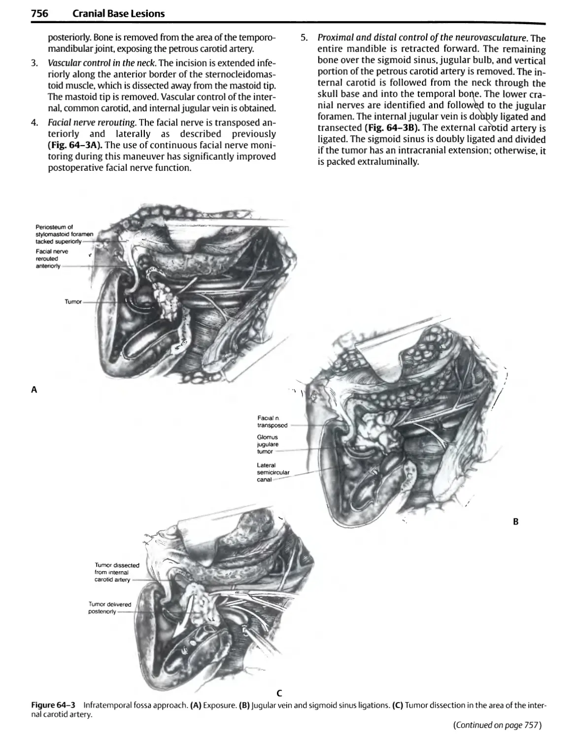
(Continued) Figure 1-1 (D) Positioning for
transsphenoidal surgery. The surgeon is
positioned on the right side of the patient and the
anesthesiologist on the left side. The patient's
head is rotated slightly to the right and tilted to
the left to provide the surgeon with a view
directly up the patient's nose. The microscope
stand is located just outside the C-arm on the
fluoroscopy unit. The scrub nurse and Mayo
stand are positioned near the patient's head
above one arm of the fluoroscopy unit. The
image-guiding camera is positioned so the surgeon
does not block its view of the operative site.
selected for procedures in the frontal, temporal, and
anterior parietal areas and for many skull base approaches. The
three-quarter prone position with the table tilted to elevate
the head is used for exposure of the posterior parietal,
occipital, and suboccipital areas (Figs. 1-1B,C and 1-3A).
Some surgeons still prefer to have the patient in the
semisitting position for operations in the posterior fossa and
cervical region because the improved venous drainage may
reduce bleeding and because cerebrospinal fluid and blood
do not collect in the depth of the exposure. Tilting the
whole table to elevate the head of the patient in the lateral
oblique position also reduces venous engorgement at the
operative site. Extreme turning of the head and neck, which
may lead to obstruction of venous drainage from the head,
should be avoided. Points of pressure or traction on the
patient's body should be examined and protected.
Careful positioning of operating room personnel and
equipment ensures greater efficiency and effectiveness. The
anesthesiologist is positioned near the head and chest on
the side toward which the head is turned to provide easy
access to the endotracheal tube and the intravenous and in-
tra-arterial lines, rather than at the foot of the patient,
where access to support systems is limited (Fig. 1-1). If the
patient is in the supine or three-quarter prone position, the
anesthesiologist is positioned on the side toward which the
face is turned, and the surgical technologist is positioned at
the other side, with the surgeon seated at the head of the
patient (i.e., for a left frontal or frontotemporal approach,
the anesthesiologist is positioned on the patient's right side,
and the scrub nurse is on the left side).
It is easiest to position the operating team when
instruments are placed on Mayo stands that can be moved around
the patient. In the past, large, heavy overhead stands with
many instruments were positioned above the body of the
patient. Mayo stands, which are lighter and more easily
moved, allow the scrub nurse and the instruments to be
positioned and repositioned at the optimal site to assist the
surgeon. They also allow the flexibility required by the more
frequent use of intraoperative fluoroscopy, image guidance,
and angiography. The control console for drills, suction, and
coagulation is usually positioned at the foot of the
operating table, and the tubes and lines are led upward to the
operative site.
In the past, it was common to shave the whole head for
most intracranial operations, but hair removal now
commonly extends only 1.5 to 2.0 cm beyond the margin of the
incision. Care must be taken to shave and drape a wide
enough area to allow extension of the incision if a larger
operative field is needed and to allow drains to be led out
through stab wounds. Some surgeons currently do not
remove hair in preparation for a scalp incision and
craniotomy. It may be helpful in supratentorial operations to
outline several important landmarks on the scalp prior to
applying the drapes. Sites commonly marked include the
coronal, sagittal, and lambdoid sutures; the rolandic and
sylvian fissures; and the pterion, inion, asterion, and
keyhole (Fig. 1-4).
Scalp flaps should have a broad base and adequate blood
supply (Fig. 1-2). A pedicle that is narrower than the
width of the flap may result in the flap edges becoming
Chapter 1 General Principles of and Instrumentation for Cranial Surgery
7
Air Dri
Temporalis Muscle
Methyl
Methacrylate
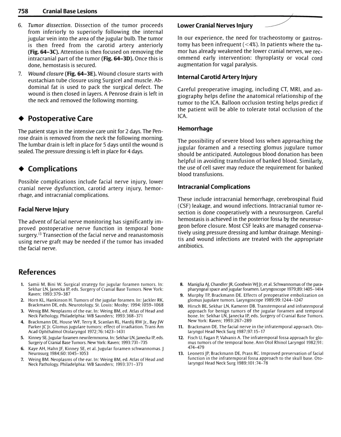
Figure 1 -2 Technique of craniotomy using a high-speed air or electric
drill. (A) Right frontotemporal scalp and free bone flaps are outlined.
(B) The scalp flap has been reflected forward and the temporalis muscle
downward. Elevating the temporalis muscle with careful subperiosteal
dissection using a periosteal elevator, rather than the cutting Bovie, aids
in preserving the muscle's nerve and vascular supply, which course in the
periosteal attachments of the muscle to the bone. The high-speed drill
prepares bur holes along the margin of the bone flap (dashed line).
(C) A narrow tool with a foot plate to protect the dura connects the
holes. (D) Cross-sectional view of the cutting tool to show how the foot
plate strips the dura away from the bone. (E) The high-speed drill
removes the lateral part of the sphenoid ridge. A drill bit makes holes in the
bone edge for tack-up sutures to hold the dura against the bony margin.
(F) After completion of the intradural part of the operation, the bone flap
is held in place with plates and screws, or bur hole covers that align the
inner and outer tables of the bone flap and adjacent skull. Silk sutures
brought through drill holes in the margin of the bone flap may be used
but do not prevent the degree of inward settling of the bone flap that is
achieved with plating. Some methylmethacrylate may be molded into
some bur holes or other openings in the bone to give a firm cosmetic
closure. (With permission from Rhoton AL Jr. Operative techniques and
instrumentation for neurosurgery. Neurosurgery 2003;53:907-934.2)
gangrenous. An effort is made to make scalp incisions
behind the hair line and not on the exposed part of the
forehead. A bicoronal incision situated behind the hair line is
preferred to extending an incision low on the forehead for a
unilateral frontal craniotomy. An attempt is made to avoid
the branch of the facial nerve that passes across the zygoma
to reach the frontalis muscle. Incisions reaching the zygoma
more than 1.5 cm anterior to the ear commonly interrupt
this nerve unless the layers of the scalp in which it courses
are protected.3 The superficial temporal and occipital
arteries should be preserved if there is the possibility that they
will be needed for an extracranial to intracranial arterial
anastomosis.
In elevating a scalp flap, the pressure of the surgeon's and
assistant's fingers against the skin on each side of the
incision is usually sufficient to control bleeding until
hemostatic clips or clamps are applied. The skin is usually incised
with a sharp blade, but the deeper fascial and muscle layers
may be incised with cutting Bovie electrocautery. The
ground plate on the electrocutting unit should have a broad
base of contact to prevent the skin at the ground plate from
being burned. Achieving a satisfactory cosmetic result with
a supratentorial craniotomy often depends on preservation
of the bulk and viability of the temporalis muscle. This is
best achieved by avoiding use of the cutting Bovie in
elevating the muscle from the bone. Both the vascular and nerve
supply of the temporalis muscle course tightly along the
fascial attachments of the muscle to the bone where they
could easily be damaged by a hot cutting instrument.3
Optimal preservation of the muscle's bulk is best achieved by
separation of the muscle from the bone using accurate
dissection with a sharp periosteal elevator.
Bipolar coagulation is routinely used to control bleeding
from the scalp margins, on the dura, and at intracranial sites.
8 Introduction
Sig. Sinus
Trans. Sinus
VIII
VII
S.C.A.
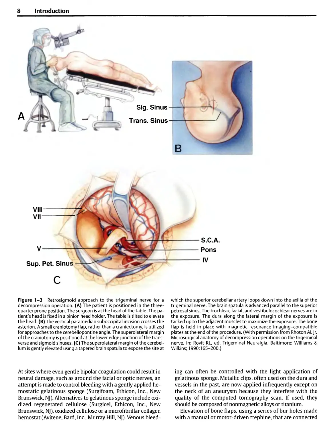
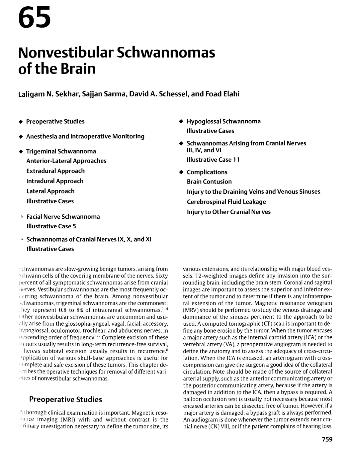
Figure 1-3 Retrosigmoid approach to the trigeminal nerve for a
decompression operation. (A) The patient is positioned in the three-
quarter prone position. The surgeon is at the head of the table. The
patient's head is fixed in a pinion head holder. The table is tilted to elevate
the head. (B) The vertical paramedian suboccipital incision crosses the
asterion. A small craniotomy flap, rather than a craniectomy, is utilized
for approaches to the cerebellopontine angle. The superolateral margin
of the craniotomy is positioned at the lower edge junction of the
transverse and sigmoid sinuses. (C) The superolateral margin of the
cerebellum is gently elevated using a tapered brain spatula to expose the site at
which the superior cerebellar artery loops down into the axilla of the
trigeminal nerve. The brain spatula is advanced parallel to the superior
petrosal sinus. The trochlear, facial, and vestibulocochlear nerves are in
the exposure. The dura along the lateral margin of the exposure is
tacked up to the adjacent muscles to maximize the exposure. The bone
flap is held in place with magnetic resonance imaging-compatible
plates at the end of the procedure. (With permission from Rhoton ALJr.
Microsurgical anatomy of decompression operations on the trigeminal
nerve. In: Rovit RL, ed. Trigeminal Neuralgia. Baltimore: Williams &
Wilkins; 1990:165-200.)
At sites where even gentle bipolar coagulation could result in
neural damage, such as around the facial or optic nerves, an
attempt is made to control bleeding with a gently applied
hemostatic gelatinous sponge (Surgifoam, Ethicon, Inc., New
Brunswick, NJ). Alternatives to gelatinous sponge include
oxidized regenerated cellulose (Surgicel, Ethicon, Inc., New
Brunswick, NJ), oxidized cellulose or a microfibrillar collagen
hemostat (Avitene, Bard, Inc., Murray Hill, NJ). Venous
bleeding can often be controlled with the light application of
gelatinous sponge. Metallic clips, often used on the dura and
vessels in the past, are now applied infrequently except on
the neck of an aneurysm because they interfere with the
quality of the computed tomography scan. If used, they
should be composed of nonmagnetic alloys or titanium.
Elevation of bone flaps, using a series of bur holes made
with a manual or motor-driven trephine, that are connected
Chapter 1 General Principles of and Instrumentation for Cranial Surgery 9
50%
Rolandic Fissure
75%
Sylvian Fissure
Sagittal Suture
Lambdoid Suture
Inion
Asterion
Coronal Suture
Temporal Line
Pterion
Keyhole
Frontal Dura
Periorbita
Frontonasal Suture
(Nasion)
Frontozygomatic Suture
(Point)
Figure 1-4 Sites commonly marked on the scalp before applying the
drapes include the coronal, sagittal, and lambdoid sutures; the rolandic
and sylvian fissures; and the pterion, inion, asterion, and keyhole.
Approximating the site of the sylvian and rolandic fissures on the scalp
begins by noting the position of the nasion, inion, and frontozygomatic
point. The nasion is located in the midline at the junction of the nasal
and frontal bones. The inion is the site of a bony prominence that
overlies the torcula. The frontozygomatic point is located on the orbital rim
2.5 cm above the level where the upper edge of the zygomatic arch joins
the orbital rim and just below the junction of the lateral and superior
margins of the orbital rim. The next steps are to construct a line along
the sagittal suture and, using a flexible measuring tape, to determine
the distance along this line from the nasion to the inion and mark the
midpoint and three-quarter points (50 and 75% points). The sylvian
fissure is located along a line that extends backward from the
frontozygomatic point across the lateral surface of the head to the three-quarter
point. The pterion, the site on the temple approximating the lateral end
of the sphenoid ridge, is located 3 cm behind the frontozygomatic point
on the sylvian fissure line. The rolandic fissure is located by identifying
the upper and lower rolandic points. The upper rolandic point is located
2 cm behind the midpoint (50% plus 2 cm point) on the nasion to inion
midsagittal line. The lower rolandic point is located where a line
extending from the midpoint of the upper margin of the zygomatic arch to the
upper rolandic point crosses the line defining the sylvian fissure. A line
connecting the upper and lower rolandic points approximates
the rolandic fissure. The lower rolandic point is located —2.5 cm behind
the pterion on the sylvian fissure line. Another important point is the
keyhole, the site of a bur hole, which if properly placed, has the frontal
dura in the depths of its upper half and the periorbita in its lower half. It
is ~3 cm anterior to the pterion, just above the lateral end of the
superior orbital rim and under the most anterior point of attachment of the
temporalis muscle and fascia to the temporal line. (With permission
from Rhoton AL Jr. The cerebrum. Neurosurgery 2002;51 (Suppl 4):
S11-S51.)
with a Gigli's wire saw, has given way to the use of
highspeed drills for making bur holes and cutting the margin of
a bone flap (Fig. 1-2). Commonly, a hole is prepared using a
cutting bur on a high-speed drill, and a tool with a foot
plate to protect the dura cuts around the margins of the
flap. Extremely long bone cuts should be avoided, especially
if they extend across an internal bony prominence such as
the pterion or across a major venous sinus. The risk of
tearing the dura or injuring the brain is reduced by drilling
several holes and making shorter cuts. A hole is placed on each
side of a venous sinus, and the dura is carefully stripped
from the bone, after which the bone cut is completed rather
than cutting the bone above the sinus as a part of a long cut
around the whole margin of the flap. Bleeding from bone
edges is stopped by the application of bone wax. Bone wax
is also used to close small openings into the mastoid air
cells and other sinuses, but larger openings in the sinuses
are closed with other materials, such as fat, muscle, or a
pericranial graft, sometimes used in conjunction with a thin
plate of methylmethacrylate or other bone substitute.
After elevating the bone flap, it is common practice to
tack the dura up to the bony margin with a few 3-0 black
silk sutures brought through the dura and then through
small drill holes in the margin of the cranial opening
(Fig. 1-2). If the bone flap is large, the dura is also
"snugged up" to the intracranial side of the bone flap with
the use of a suture brought through drill holes in the
central part of the flap. Care is taken to avoid placing drill
holes for tack-up sutures that might extend into the
frontal sinus or mastoid air cells. Tack-up sutures are more
commonly used for dura over the cerebral hemispheres
than over the cerebellum. If the brain is pressed tightly
against the dura, the tack-up sutures are placed after
dealing with the intradural pathology when the brain is
relaxed and the sutures can be placed with direct vision of
the deep surface of the dura. Tack-up sutures can also be
10 Introduction
led through adjacent muscles or pericranium rather than a
hole in the margin of the bone flap.
In the past, there was a tendency for bone flaps to be
elevated and replaced over the cerebral hemispheres and for
exposures in the suboccipital region to be done as
craniectomies without replacement of the bone. Laterally placed
suboccipital exposures are now commonly done as
craniotomies with replacement of the bone flaps. Midline
suboccipital operations are more commonly done as
craniectomies, especially if decompression at the foramen magnum
is needed, because this area is protected by a greater
thickness of overlying muscles.
Bone flaps are usually held in place with nonmagnetic
plates and screws or small metal disks or bur hole covers
that compress and align the inner and outer table of the
bone flap and the adjacent skull (Fig. 1-2F). Remaining
defects in the bone are commonly covered with metal disks or
filled with methylmethacrylate that is allowed to harden in
place before the scalp is closed.
The dura is closed with 3-0 silk interrupted or running
sutures. Small bits of fat or muscle may be sutured over
small openings caused by shrinkage of the dura. Larger
dural defects are closed with pericranium or temporalis
fascia taken from the operative site or with sterilized cadaveric
dura or fascia lata, or other approved dural substitutes. The
deep muscles and fascia are commonly closed with 1-0, the
temporalis muscle and fascia with 2-0, and the galea with
3-0 synthetic absorbable suture. The scalp is usually closed
with metallic staples, except at sites where some 3-0 or 5-0
nylon reinforcing sutures may be needed. Skin staples are
associated with less tissue reaction than other forms of
closure with sutures.
Head Fixation Devices
Precise maintenance of the firmly fixed cranium in the
optimal position greatly facilitates the operative exposure
(Figs. 1-5,1-6). Fixation is best achieved by a pinion head
Figure 1-5 Positioning of a pinion head holder for craniotomy. Three pins
penetrate the scalp and are firmly fixed to the outer table of the skull.
(A) Position of the head holder for a unilateral or bilateral frontal approach.
(B) Position for a pterional orfrontotemporal craniotomy. (C) Position for ret-
rosigmoid approach to the cerebellopontine angle. (D) Position for a midline
suboccipital approach. (E) Position for a midline suboccipital approach with
the patient in the semisitting position. The pins are positioned to avoid the
thin bone over the frontal sinus or mastoid air cells and the temporalis
muscle. The side arms of the head clamp should be shaped to accommodate the
C-clamps for holding the retractor system. The pinion head holder has a bolt
that resembles a sunburst for attaching it to the surgical table. Placing three
sunburst sites on the head clamp, rather than only one, allows greater
flexibility in attaching the head clamp to the surgical table and provides extra
sites for the attachment of retractor systems and instruments for instrument
guidance. (With permission from Rhoton ALJr. Operative techniques and
instrumentation for neurosurgery. Neurosurgery 2003;53:907-934.)
Chapter 1 General Principles of and Instrumentation for Cranial Surgery
11
holder in which the essential element is a clamp made to
accommodate three relatively sharp pins. When the pins
are placed, care should be taken to avoid a spinal fluid
shunt, thin bones such as overlie the frontal and mastoid
sinuses, and the thick temporalis muscle, where the clamp,
however tightly applied, tends to remain unstable. The pins
should be applied well away from the eye or where they
would be a hindrance to making the incision. Special
shorter pediatric pins are available for thin skulls. The pins
should not be placed over the thin skulls of some patients
with a history of hydrocephalus. After the clamp is secured
on the head, the final positioning is done, and the head
holder is fixed to the operating table.
This type of immobilization allows intraoperative
repositioning of the head. The clamp avoids the skin damage that
may occur if the face rests against a padded head support
for several hours. The skull clamps do not obscure the face
during the operation as do padded headrests, facilitating
intraoperative electromyographic monitoring of the facial
muscles and monitoring of auditory or somatosensory evoked
potentials. Until recently, all the head clamps were
constructed of radiopaque metals, but the increasing use of
intraoperative fluoroscopy and angiography has prompted the
development of head holders constructed of radiolucent
materials. The pinion head clamp commonly serves as the
site of attachment of the brain retractor system. The side
YES
Figure 1 -6 Positioning patients for acoustic neuroma removal and
decompression for hemifacial spasm. (A) and (B) Elevation of the head of the
table. (A) In our initial use of the three-quarter prone position, the head of
the operating table was tilted to elevate the head only slightly, but it was
later found that (B) more marked tilting of the table significantly elevated
the head and reduced the venous distension and intracranial pressure.
The author usually does operations for acoustic neuromas and hemifacial
spasm sitting on a stool positioned behind the head of the patient. In
recent years, we have tilted the table to elevate the head to a degree that
the surgeon's stool must be placed on a platform. The patient should be
positioned on the side of the table nearest the surgeon. (C) and (D)
Rotation of the head. (C) There is a tendency to rotate the face toward the
floor for acoustic neuroma removal. (D) However, better operative access
is obtained if the sagittal suture is placed parallel to the floor. Rotating the
face toward the floor as in (C) places the direction of view through the
operating microscope forward toward the shoulder, thus blocking or
reducing the operative angle. Positioning the head so that the sagittal suture is
parallel to the floor as in (D) allows the direction of view of the operating
microscope to be rotated away from the shoulder and provides easier and
wider access to the operative field. The position shown in (D) is also used
for decompression operations for hemifacial spasm. The position shown
in (C) is used for decompression operations for trigeminal neuralgia, in
which the surgeon is seated at the top of the patient's head as shown in
Fig. 1-3A rather than behind the patient's head as shown in (B).
[Continued on page 12)
12 Introduction
NO
- MILD TILT
YES - MILD FLEXION
(Continued) Figure 1-6 (E) Rather than tilting the head toward the
ipsilateral shoulder, it is better to (F) tilt the head gently toward the
contralateral shoulder. Tilting the vertex toward the floor with the sagittal
suture parallel to the floor aids in opening the angle between the shoulder
and head and increases operative access. (C) Extending the neck tends to
shift the operative site toward the prominence of the shoulder and upper
chest, whereas (H) gentle flexion opens the angle between the upper
chest and operative site and broadens the range of access to the operative
site. (With permission from Rhoton ALJr. Operative techniques and
instrumentation for neurosurgery. Neurosurgery 2003;53: 907-934.2)
arms of the head clamp should be shaped to accommodate
the C-clamps for holding the retractor system. The pinion
head holder has a bolt that resembles a sunburst for
attaching it to the surgical table. Placing three sunburst sites on
the head clamp, rather than only one, allows greater
flexibility in attaching the head clamp to the surgical table and
provides extra sites for the attachment of retractor systems
and components of the image guidance system.
¦ Instrument Selection
Optimizing operative results requires the careful selection
of instruments for the macrosurgical portion of the
operation done with the naked eye and the microsurgical part
done with the eye aided by the operating microscope.4,5 In
the past, surgeons commonly used one set of instruments
for performing conventional macrosurgery with the naked
eye and another set with different handles and smaller tips
for microsurgery done with the eye aided by the
microscope. A trend is to select instruments having uniform
handles and tactile characteristics for macrosurgery and
microsurgery and to change only the size of the tip of the
instrument, depending on whether the use is to be macro-
or microsurgical. For example, forceps for macrosurgery
have grasping tips as large as 2 to 3 mm, and those for
microsurgery commonly have tips measuring 0.3 to 1.0 mm.
If possible, the instruments should be held in a pencil
grip between the thumb and the index finger rather than in
a pistol grip with the whole hand (Fig. 1-7). The pencil grip
permits the instruments to be positioned by delicate
movements of the fingers, but the pistol grip requires that the
instruments be manipulated with the coarser movements of
the wrist, elbow, and shoulder.
The author prefers round-handled forceps, scissors, and
needle holders because they allow finer movement. It is
possible to rotate these instruments between the thumb
and forefinger rather than having to rotate the entire wrist
(Fig. 1-8). The author first used round-handled needle
holders and scissors in performing superficial temporal to
middle cerebral artery anastomosis and later found that the
advantage of being able to rotate the instrument between
Chapter 1 General Principles of and Instrumentation for Cranial Surgery
13
Figure 1 -7 Common hand grips for holding a surgical instrument. The
grip is determined largely by the design of the instrument. (A) A suction
tube is held in a pistol grip. The disadvantage of this type of grip is that it
uses movements at the wrist and elbow rather than fine finger
movements to position the tip of the instrument, and the hand cannot be
rested arid stabilized on the wound margin. (B) A suction tube is held in
a pencil grip, permitting manipulation of the tip with delicate finger
movements while the hand rests comfortably on the wound margin.
the thumb and the fingers also improved the accuracy of
other straight and bayonet instruments used for dissection,
grasping, cutting, and coagulation (Figs. 1-9,1-10). Round-
handled straight and bayonet forceps may be used for both
macrosurgery and microsurgery.
The addition of straight round-handled forceps with
teeth, called tissue forceps, increases the use of the set of
round-handled instruments to include grasping muscle,
skin, and dura (Fig. 1-11). A tissue forceps with large teeth
is used on the scalp and muscle, and ones with small teeth
are used on dura. The addition of round-handled dressing
forceps, which have fine serrations inside the tips, makes
the set suitable for grasping arterial walls for endarterec-
tomy and arterial suturing.
The instruments should have a dull finish because the
brilliant light from highly polished instruments reflected
back through the microscope can interfere with the
surgeon's vision and detract from the quality of photographs
taken through the microscope. Sharpness and sterilization
are not affected by the dull finish. The separation between
the instrument tips should be wide enough to allow them
to straddle the tissue, the needle, or the thread to cut or
grasp it accurately. The excessive opening and closing
movements required for widely separated tips reduce the
functional accuracy of the instrument during delicate
manipulation under the operating microscope. The finger
pressure required to bring widely separated tips together
against firm spring tension often initiates a fine tremor and
inaccurate movement. Microsurgical tissue forceps should
have a tip separation of no more than 8 mm; microneedle
holder tips should open no more than 3 mm; and
microscissors tips should open no less than 2 mm and no more than
5 mm, depending on the length of the blade and the use of
the scissors.
The length of the instruments should be adequate for the
particular task that is being contemplated (Figs. 1-9,1-10).
Bayonet instruments (e.g., forceps, needle holders, and
scissors) should be available in at least the three lengths
needed for the hand to be rested while the surgeon
operates at superficial, deep, and extra deep sites.
Bayonet Forceps
Bayonet forceps are standard neurosurgical instruments
(Figs. 1-9,1-10). The bayonet forceps'should be properly
balanced so that when its handle rests on the web between
the thumb and index finger and across the radial side of the
middle finger it remains there without falling forward
when the grasp of the index finger and thumb is released.
Poor balance prevents the delicate grasp needed for
microsurgical procedures.
It is preferable to test forceps for tension and tactile
qualities by holding them in the gloved rather than the naked
hand. Forceps resistance to closure that is perceived as
adequate in the naked hand may become almost imperceptible
in the gloved hand. The forceps may be used to develop
tissue planes by inserting the closed forceps between the
structures to be separated and releasing the tension so that
the blades open and separate the structures. This form of
dissection requires greater tension in the handles than is
found in some delicate forceps.
In selecting bayonet forceps, the surgeon should consider
the length of the blades needed to reach the operative site
14 Introduction
Figure 1 -8 Straight Rhoton instruments with round handles and fine for tying fine suture, bipolar forceps with 0.3 and 0.5 mm tips, and plain
tips for use at the surface of the brain. These instruments are suitable for and bipolar jeweler's forceps. The jeweler's forceps can be used as a nee-
microsurgical procedures, such as an extracranial to intracranial arterial die holder for placing sutures in a fine microvascular anastomosis on the
anastomosis. The instruments include needle holders with straight and surface of the brain, but the author prefers a straight, round-handled
curved tips, scissors with straight and curved tips, forceps with platforms needle holder for that use.
Chapter 1 General Principles of and Instrumentation for Cranial Surgery
15
DEPTH
INSTRUMENT LENGTH
SUPERFICIAL
8 cm 95 cm 11 cm
-! h
DEEP 9.5 cm
Deep Under Brain Circle or Willis,
Sellar Region CP Angle
EXTRA DEEP 11cm
Extra Deep Under Brain, Front or
Brain Stem, Transsphenoidal
4
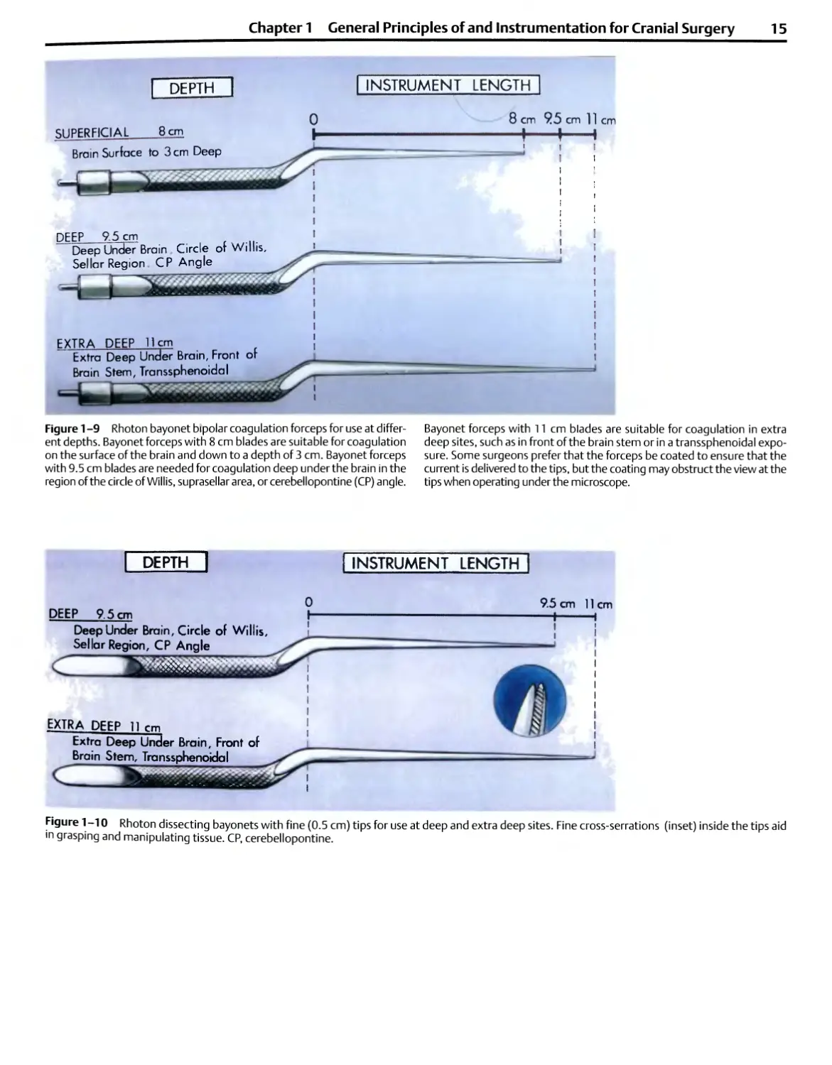
Figure 1 -9 Rhoton bayonet bipolar coagulation forceps for use at
different depths. Bayonet forceps with 8 cm blades are suitable for coagulation
on the surface of the brain and down to a depth of 3 cm. Bayonet forceps
with 9.5 cm blades are needed for coagulation deep under the brain in the
region of the circle of Willis, suprasellar area, or cerebellopontine (CP) angle.
Bayonet forceps with 11 cm blades are suitable for coagulation in extra
deep sites, such as in front of the brain stem or in a transsphenoidal
exposure. Some surgeons prefer that the forceps be coated to ensure that the
current is delivered to the tips, but the coating may obstruct the view at the
tips when operating under the microscope.
DEEP 9.5 cm
Deep Under Brain, Circle of Willis,
Sellar Region, CP Angle
c
EXTRA DEEP 11 rm
Extra Deep Under Brain, Front of
Brainstem, Transsphenoidal
INSTRUMENT LENGTH
9.5 cm 11
—I
cm
Figure 1-10 Rhoton dissecting bayonets with fine (0.5 cm) tips for use at deep and extra deep sites. Fine cross-serrations (inset) inside the tips aid
m grasping and manipulating tissue. CP, cerebellopontine.
16 Introduction
Figure 1-11 Rhoton straight instruments with round handles are
needed to complete the set so that the same type of handles can
be used for macrosurgery done with the naked eye and microsurgery
done with the eye aided by the microscope. Forceps with teeth, called
tissue forceps, are needed for grasping dura, muscle, and skin. Small
teeth are used on dura, and large teeth are used for skin and muscle.
Forceps with cross-serrations, called dressing forceps, may be used
during an endarterectomy on larger arteries. Smooth-tip bipolar
coagulation forceps with 1.5 mm tips are used for macrocoagulation of large
vessels in the scalp, muscle, or dura.
and the size of the tip needed for the specific task to be
completed. Bayonet forceps with 8.0, 9.5, and 11.0 cm
blades in a variety of tip sizes ranging from 0.5 to 2.0 mm
are needed (Figs. 1-9 and 1-10). Bayonet forceps with an
8.0 cm shaft are suitable for use on the brain surface and
down to a depth of 2.0 cm below the surface. Bayonet
forceps with blades of 9.5 cm are suitable for manipulating
tissues deep under the brain at the level of the circle of Willis
(e.g., in an aneurysm operation), in the sellar region (e.g., in
a transcranial approach to a pituitary tumor), and in the
cerebellopontine angle (e.g., for removal of an acoustic
neuroma or decompression of a cranial nerve). For dissection
and coagulation in extra deep sites, such as in front of the
brain stem or in the depths of a transsphenoidal exposure,
forceps having blades of 11 cm are used. Some surgeons
prefer that the forceps be coated with an insulating
material except at the tips to ensure that the current is delivered
to the tips, but the coating, if thick, may obstruct the view
of the tissue being grasped when operating under the
microscope.
A series of bipolar bayonet forceps having tips of 0.3 to
2.0 mm will allow coagulation of a vessel of almost any size
encountered in neurosurgery (Fig. 1-12). For coagulating
larger structures, tips with widths of 1.5 and 2.0 mm are
needed. For microcoagulation, forceps with 1.0, 0.7, or
0.5 mm tips are selected. The fine 0.3 mm tips, like those
found on jeweler's forceps, when placed on bayonet forceps
may scissor rather than firmly opposing unless carefully
aligned. A 0.5 mm tip is the smallest that is practical for use
on many bayonet forceps. The forceps should have smooth
tips if they are to be used for bipolar coagulation. If they are
used for dissecting and grasping tissue and not for
coagulation, the inside tips should have fine cross-serrations like
dressing forceps (Fig. 1-10 and 11). For grasping large
pieces of tumor capsule, forceps with small rings with fine
serrations at the tips may be used.
Bipolar Coagulation
The bipolar electrocoagulator has become fundamental to
neurosurgery because it allows accurate, fine coagulation of
small vessels, minimizing dangerous spread of current to
adjacent neural and vascular structures (Figs. 1-9, 1-12,
1-13).67 It allows coagulation in areas where unipolar
coagulation would be hazardous, such as near the cranial nerves,
brain stem, cerebellar arteries, and fourth ventricle.
When the electrode tips touch each other, the current is
short-circuited, and no coagulation occurs. There should be
enough tension in the handle of the forceps to allow the
surgeon to control the distance between the tips because no
coagulation occurs if the tips touch or are too far apart.
Some types of forceps, attractive for their delicacy,
compress with so little pressure that a surgeon cannot avoid
closing them during coagulation, even with a delicate grasp.
The cable connecting the bipolar unit and the coagulation
forceps should not be excessively long because longer
cables can cause an irregular supply of current.
Surgeons with experience in conventional coagulation are
conditioned to require maximal dryness at the surface of
application, but with bipolar coagulation, some moistness is
preferable. Coagulation occurs even if the tips are immersed
Chapter 1 General Principles of and Instrumentation for Cranial Surgery
17
Z
o
3
o
u
O
2
Z
O
2.0 mm
1.5mm
1.0 mm
0.7mm
0.5 mm
0.3 mm
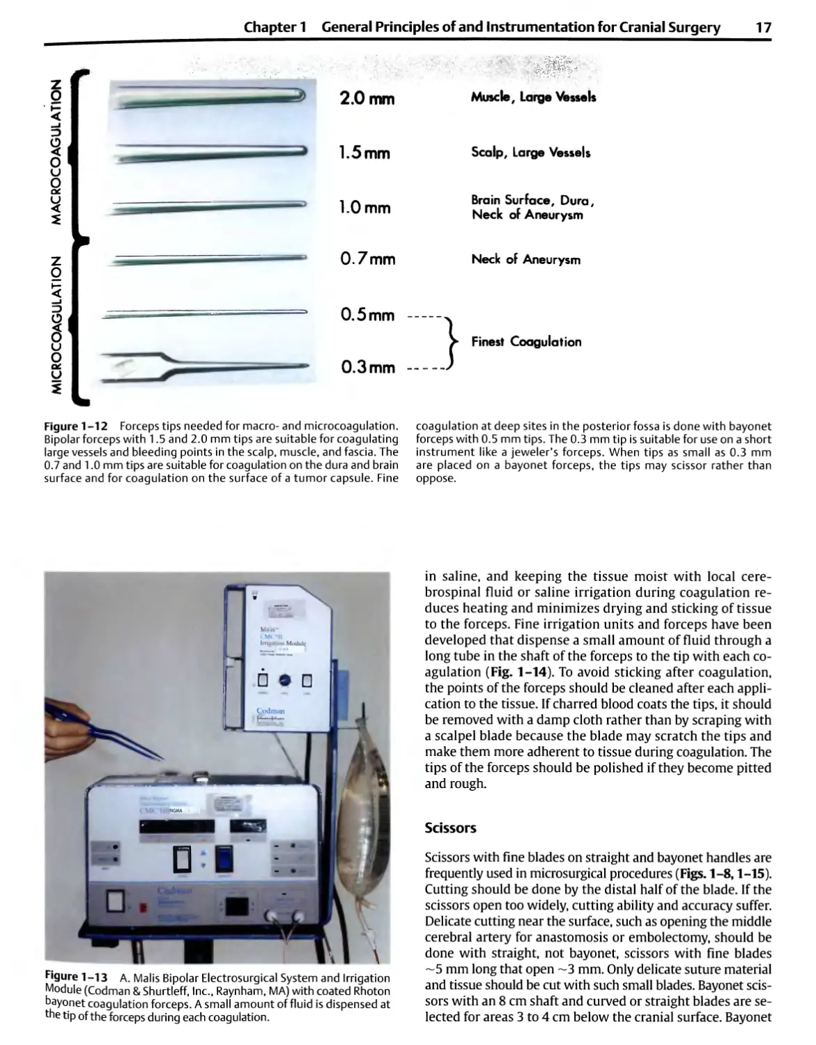
Figure 1-12 Forceps tips needed for macro- and microcoagulation.
Bipolar forceps with 1.5 and 2.0 mm tips are suitable for coagulating
large vessels and bleeding points in the scalp, muscle, and fascia. The
0.7 and 1.0 mm tips are suitable for coagulation on the dura and brain
surface and for coagulation on the surface of a tumor capsule. Fine
Muscle, Large Vessels
Scalp, Large Vessels
Brain Surface, Dura,
Neck of Aneurysm
Neck of Aneurysm
Finest Coagulation
coagulation at deep sites in the posterior fossa is done with bayonet
forceps with 0.5 mm tips. The 0.3 mm tip is suitable for use on a short
instrument like a jeweler's forceps. When tips as small as 0.3 mm
are placed on a bayonet forceps, the tips may scissor rather than
oppose.
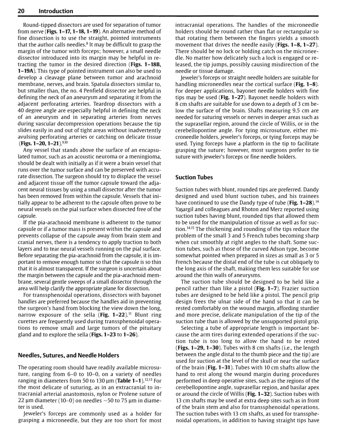
Figure 1-13 A. Malis Bipolar Electrosurgical System and Irrigation
Module (Codman & Shurtleff, Inc., Raynham, MA) with coated Rhoton
bayonet coagulation forceps. A small amount of fluid is dispensed at
the tip of the forceps during each coagulation.
in saline, and keeping the tissue moist with local
cerebrospinal fluid or saline irrigation during coagulation
reduces heating and minimizes drying and sticking of tissue
to the forceps. Fine irrigation units and forceps have been
developed that dispense a small amount of fluid through a
long tube in the shaft of the forceps to the tip with each
coagulation (Fig. 1-14). To avoid sticking after coagulation,
the points of the forceps should be cleaned after each
application to the tissue. If charred blood coats the tips, it should
be removed with a damp cloth rather than by scraping with
a scalpel blade because the blade may scratch the tips and
make them more adherent to tissue during coagulation. The
tips of the forceps should be polished if they become pitted
and rough.
Scissors
Scissors with fine blades on straight and bayonet handles are
frequently used in microsurgical procedures (Figs. 1-8,1-15).
Cutting should be done by the distal half of the blade. If the
scissors open too widely, cutting ability and accuracy suffer.
Delicate cutting near the surface, such as opening the middle
cerebral artery for anastomosis or embolectomy, should be
done with straight, not bayonet, scissors with fine blades
~5 mm long that open ~3 mm. Only delicate suture material
and tissue should be cut with such small blades. Bayonet
scissors with an 8 cm shaft and curved or straight blades are
selected for areas 3 to 4 cm below the cranial surface. Bayonet
18 Introduction
SUPERFICIAL 8 cm
8 cm 95 cm
Figure 1-14 Rhoton irrigating bipolar forceps. A small amount of fluid is
dispensed at the tip of the forceps during each coagulation. The small
metal tube that carries the irrigating fluid is inlaid into the shaft of the
instrument so that it does not obstruct the view when the surgeon is
looking down the forceps into a deep, narrow operative site. The irrigating
forceps with 8 cm blades are suitable for coagulation at or near the
surface of the brain. Bayonet forceps with 9.5 cm blades are used for
coagulation deep under the brain. Some surgeons prefer that the forceps be
coated to ensure that the current is delivered to the tips, but the coating
may obstruct the view at the tips when operating under the microscope.
SCISSORS
DEEP 9.5cm
Deep Under Brain, Circle of Willis,
Sellar Region, CP Angle
l?
EXTRA DEEP 11cm
Extra Deep Under Brain, Front of
Brain Stem
INSTRUMENT LENGTH
8 cm 9.5 cm 11cm
-+-
Figure 1-15 Rhoton bayonet scissors with straight and curved blades.
The bayonet scissors with 8 cm shafts are used at the surface of the
brain and down to a depth of 3 cm. The scissors with 9.5 cm shafts are
used deep under the brain, at the level of the circle of Willis, suprasellar
area, and in the cerebellopontine (CP) angle. The scissors with 11 cm
shafts are used at extra deep sites such as in front of the brain stem.
The straight, nonbayonet scissors shown in Fig. 1-8 may also be used at
the brain's surface.
Chapter 1 General Principles of and Instrumentation for Cranial Surgery
19
Scissors
Figure 1-16 Straight and angled alligator cup forceps and scissors. as 5 mm are occasionally needed. Straight and angled alligator
These fine cup forceps are used for grasping and removing tumor in scissors with the same mechanism of action as the cup forceps
deep, narrow exposures. A 2, 3, or 4 mm cup is required for most mi- are needed in deep, narrow exposures, as in the depths of a
crosurgical applications, but cup forceps as small as 1 mm or as large transsphenoidal operation.
scissors with a 9.5 cm shaft are selected for deep areas, such
as the cerebellopontine angle or suprasellar region. The blade
should measure 14 mm long and should open ~4 mm. For
extra deep sites, such as in front of the brain stem, the scissors
should have an 11 cm shaft. Scissors on an alligator-type
shank with a long shaft are selected for deep, narrow
openings, as in transsphenoidal operations (Fig. 1-16).
Dissectors
The most widely used neurosurgical macrodissectors are of
the Penfield or Freer types; however, the size and weight of
these instruments make them unsuitable for
microdissection around the cranial nerves, brain stem, and intracranial
vessels. The smallest Penfield dissector, the no. 4, has a
width of 3 mm. For microsurgery, dissectors with 1 and 2
mm tips are needed (Fig. 1-17). Straight, rather than
bayonet, dissectors are preferred for most intracranial operations
because rotating the handles of the straight dissector does
not alter the position of the tip, but rotating the handle of a
bayonet dissector causes the tip to move through a wide arc.
Figure 1-17 Rhoton microdissectors for neurosurgery. Beginning on the
left of the top row are four types of dissectors: round, spatula, flat, and micro-
Penfield. The next instruments, in order, along the top row are a right-angled
nerve hook, angled and straight needle dissectors, and a microcurette. The
last three instruments in the top row are straight, and 40 degree, and right-
angled teardrop dissectors. A storage case of the type shown below the
instruments permits easy access to instruments and protects the delicate
tips when not in use. The full set includes round and spatula dissectors in 1,
2, and 3 mm widths, straight and angled microcurettes, long and short
teardrop dissectors in 40 degree and right-angled configurations, and one
straight teardrop dissector.
20 Introduction
Round-tipped dissectors are used for separation of tumor
from nerve (Figs. 1-17,1-18,1-19). An alternative method of
fine dissection is to use the straight, pointed instruments
that the author calls needles.8 It may be difficult to grasp the
margin of the tumor with forceps; however, a small needle
dissector introduced into its margin may be helpful in
retracting the tumor in the desired direction (Figs. 1-18B,
1-19A). This type of pointed instrument can also be used to
develop a cleavage plane between tumor and arachnoid
membrane, nerves, and brain. Spatula dissectors similar to,
but smaller than, the no. 4 Penfield dissector are helpful in
defining the neck of an aneurysm and separating it from the
adjacent perforating arteries. Teardrop dissectors with a
40 degree angle are especially helpful in defining the neck
of an aneurysm and in separating arteries from nerves
during vascular decompression operations because the tip
slides easily in and out of tight areas without inadvertently
avulsing perforating arteries or catching on delicate tissue
(Figs. 1-20,1-21 ).910
Any vessel that stands above the surface of an
encapsulated tumor, such as an acoustic neuroma or a meningioma,
should be dealt with initially as if it were a brain vessel that
runs over the tumor surface and can be preserved with
accurate dissection. The surgeon should try to displace the vessel
and adjacent tissue off the tumor capsule toward the
adjacent neural tissues by using a small dissector after the tumor
has been removed from within the capsule. Vessels that
initially appear to be adherent to the capsule often prove to be
neural vessels on the pial surface when dissected free of the
capsule.
If the pia-arachnoid membrane is adherent to the tumor
capsule or if a tumor mass is present within the capsule and
prevents collapse of the capsule away from brain stem and
cranial nerves, there is a tendency to apply traction to both
layers and to tear neural vessels running on the pial surface.
Before separating the pia-arachnoid from the capsule, it is
important to remove enough tumor so that the capsule is so thin
that it is almost transparent. If the surgeon is uncertain about
the margin between the capsule and the pia-arachnoid
membrane, several gentle sweeps of a small dissector through the
area will help clarify the appropriate plane for dissection.
For transsphenoidal operations, dissectors with bayonet
handles are preferred because the handles aid in preventing
the surgeon's hand from blocking the view down the long,
narrow exposure of the sella (Fig. 1-22).11 Blunt ring
curettes are frequently used during transsphenoidal
operations to remove small and large tumors of the pituitary
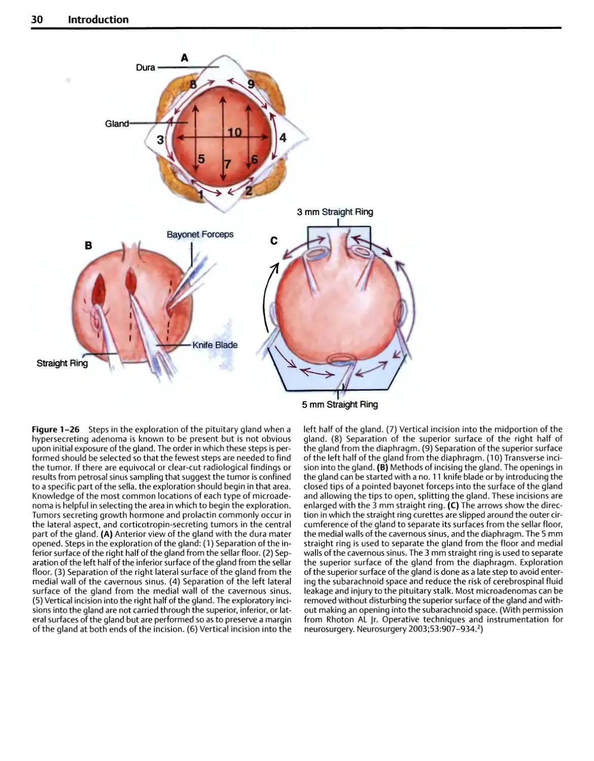
gland and to explore the sella (Figs. 1-23 to 1-26).
Needles, Sutures, and Needle Holders
The operating room should have readily available microsu-
ture, ranging from 6-0 to 10-0, on a variety of needles
ranging in diameters from 50 to 130 urn (Table 1-1 ).1213 For
the most delicate of suturing, as in an extracranial to
intracranial arterial anastomosis, nylon or Prolene suture of
22 urn diameter (10-0) on needles ~50 to 75 urn in
diameter is used.
Jeweler's forceps are commonly used as a holder for
grasping a microneedle, but they are too short for most
intracranial operations. The handles of the microneedle
holders should be round rather than flat or rectangular so
that rotating them between the fingers yields a smooth
movement that drives the needle easily (Figs. 1-8,1-27).
There should be no lock or holding catch on the
microneedle. No matter how delicately such a lock is engaged or
released, the tip jumps, possibly causing misdirection of the
needle or tissue damage.
Jeweler's forceps or straight needle holders are suitable for
handling microneedles near the cortical surface (Fig. 1-8).
For deeper applications, bayonet needle holders with fine
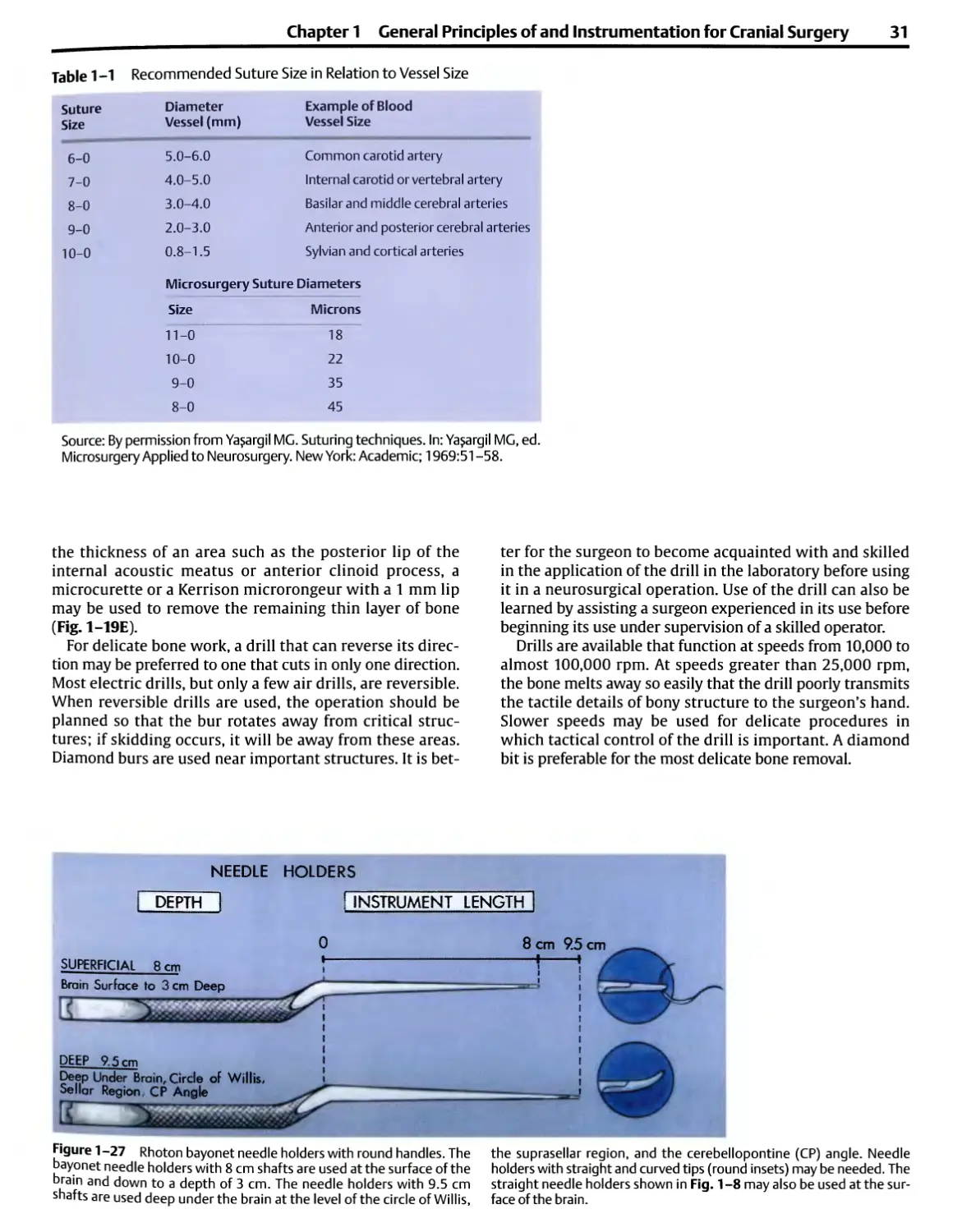
tips may be used (Fig. 1-27). Bayonet needle holders with
8 cm shafts are suitable for use down to a depth of 3 cm
below the surface of the brain. Shafts measuring 9.5 cm are
needed for suturing vessels or nerves in deeper areas such as
the suprasellar region, around the circle of Willis, or in the
cerebellopontine angle. For tying microsuture, either
microneedle holders, jeweler's forceps, or tying forceps may be
used. Tying forceps have a platform in the tip to facilitate
grasping the suture; however, most surgeons prefer to tie
suture with jeweler's forceps or fine needle holders.
Suction Tubes
Suction tubes with blunt, rounded tips are preferred. Dandy
designed and used blunt suction tubes, and his trainees
have continued to use the Dandy type of tube (Fig. 1-28).14
Ya§argil and colleagues and Rhoton and Merz reported using
suction tubes having blunt, rounded tips that allowed them
to be used for the manipulation of tissue as well as for
suction.1415 The thickening and rounding of the tips reduce the
problem of the small 3 and 5 French tubes becoming sharp
when cut smoothly at right angles to the shaft. Some
suction tubes, such as those of the curved Adson type, become
somewhat pointed when prepared in sizes as small as 3 or 5
French because the distal end of the tube is cut obliquely to
the long axis of the shaft, making them less suitable for use
around the thin walls of aneurysms.
The suction tube should be designed to be held like a
pencil rather than like a pistol (Fig. 1-7). Frazier suction
tubes are designed to be held like a pistol. The pencil grip
design frees the ulnar side of the hand so that it can be
rested comfortably on the wound margin, affording sturdier
and more precise, delicate manipulation of the tip of the
suction tube than is allowed by the unsupported pistol grip.
Selecting a tube of appropriate length is important
because the arm tires during extended operations if the
suction tube is too long to allow the hand to be rested
(Figs. 1-29,1-30). Tubes with 8 cm shafts (i.e., the length
between the angle distal to the thumb piece and the tip) are
used for suction at the level of the skull or near the surface
of the brain (Fig. 1-31). Tubes with 10 cm shafts allow the
hand to rest along the wound margin during procedures
performed in deep operative sites, such as the regions of the
cerebellopontine angle, suprasellar region, and basilar apex
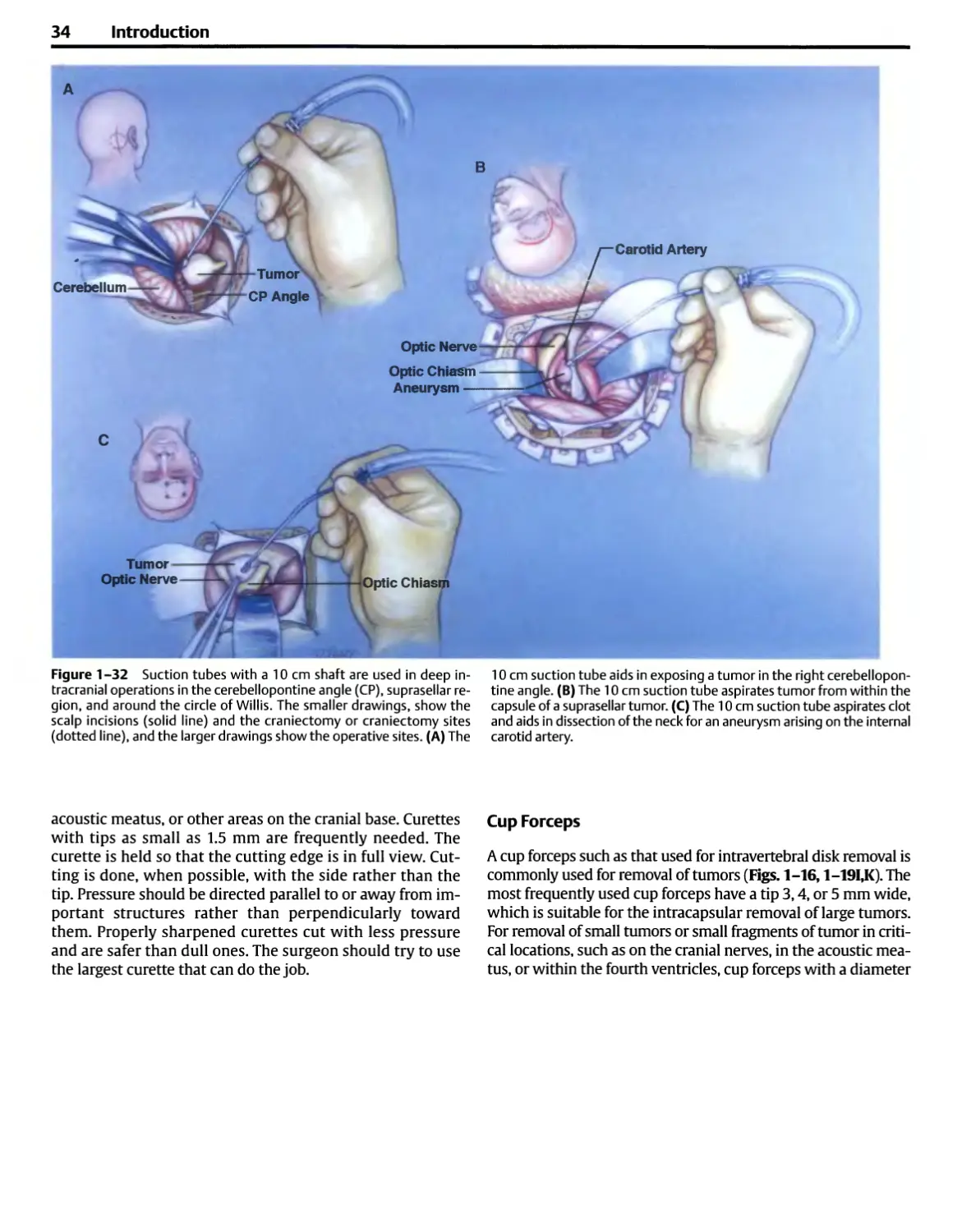
or around the circle of Willis (Fig. 1-32). Suction tubes with
13 cm shafts may be used at extra deep sites such as in front
of the brain stem and also for transsphenoidal operations.
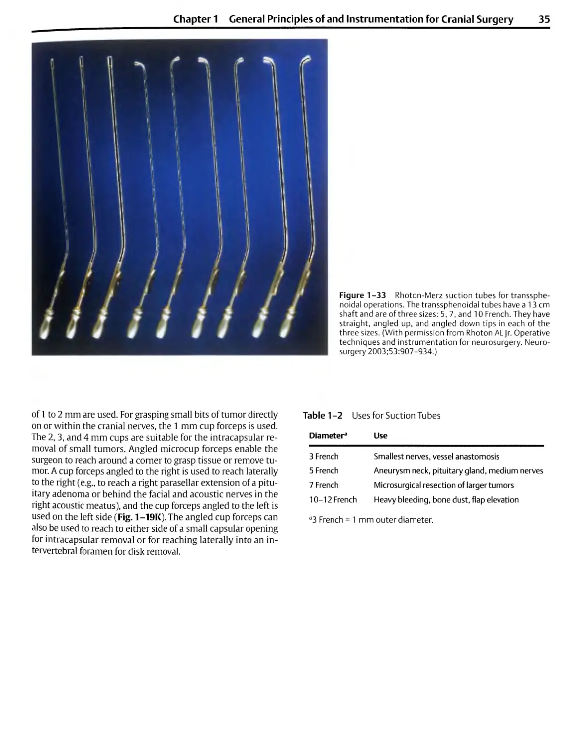
The suction tubes with 13 cm shafts, as used for
transsphenoidal operations, in addition to having straight tips have
Chapter 1 General Principles of and Instrumentation for Cranial Surgery
21
Spatula
Round Dissector
Fine Dissecting Forceps
Angled Needle
JTmTYiT
Straight Needle
Figure 1-18 Four methods of fine dissection for separating the capsule
of an acoustic neuroma from the nerves in the cerebellopontine angle.
(A) The posterior wall of the internal auditory canal has been removed,
and the entire tumor has been removed except for a small fragment of the
capsule in the lateral end of the canal behind the vestibulocochlear and
facial nerves. The angled curette is inserted in the meatal fundus behind
the nerves and lifts the last fragment of capsule out of the lateral end of
the meatus after the tumor has been separated from the posterior surface
of the nerves. (B) A small acoustic neuroma is removed from the posterior
surface of the vestibulocochlear nerve using angled and straight needles.
The straight needle is used to retract the tumor capsule, and the angled
needle separates the tumor capsule and nerve. (C) The nerve and tumor
capsule are separated with a round dissector. The strokes of the dissectors
should be directed from medial to lateral if there is a chance of preserving
hearing. The facial nerve is exposed at the lateral end of the meatus.
(D) Removal of the capsule of a large tumor from the posterior surface of
the vestibulocochlear nerve using fine dissecting bayonet forceps having
0.5 mm tips with small serrations on the inside of the tip to aid in grasping
tissue. Bayonet dissecting forceps with 9.5 cm shafts are used in deep
sites such as the cerebellopontine angle, and bayonet forceps with an
11 cm shaft are used at extra deep sites, as in front of the brain stem. The
glossopharyngeal and vagus nerves are below the tumor. (With
permission from Rhoton ALJr. Operative techniques and instrumentation for
neurosurgery. Neurosurgery 2003;53:907-934.2)
22 Introduction
Figure 1-19 Microinstruments used in the
cerebellopontine angle. This illustration was prepared
from 16 mm movie frames taken at the time of
removal of an acoustic neuroma in the right
cerebellopontine angle. This operation resulted in
preservation of the facial, acoustic, and vestibular
nerves. (A) A brain spatula gently elevates the
right cerebellum to expose the tumor. Small,
pointed instruments called needles separate the
tumor from the eighth nerve. The straight needle
retracts the tumor, and the 45 degree needle
develops a cleavage plane between the tumor and
the nerve. The facial nerve is hidden in front of the
vestibulocochlear nerve. (B) The microcurette
with a 1.5 mm cup strips dura mater from the
posterior wall of the meatus. (C)The 1 mm round
dissector separates dura from the bone at the
porus and within the meatus. (D) A drill is used
to remove the posterior wall of the meatus.
Suction irrigation cools and removes bone dust. (E)
Alternative method of removal of the posterior
wall after it has been thinned by a drill using a
Kerrison rongeur with a 1 mm wide bite. (F) The
microcurette with a 1.5 mm cup removes the last
bit of bone from the posterior meatal wall.
tips angled up and down for suction around the curves
within the capsule of a tumor or for following asymmetrical
extensions of tumor (Figs. 1-24,1-33).
The suction tubes should encompass a range of diameters
from 3 to 12 French, which allows them to be used for
macroneurosurgery and microneurosurgery (Table 1-2)
(Fig. 1-30). Conventional surgery done with the naked eye
uses 9,10, or 12 French tubes. The French designation
applies to the outer diameter. Three French units equal 1 mm;
thus a 9 French tube has an outer diameter of 3 mm. The
10 and 12 French tubes are used during the opening of the
scalp, muscle, and bone and for heavy bleeding. The most
commonly used macrosuction tubes, the 9 and 10 French
sizes, are too large for use after the dura is open. Stretched
nerve fascicles or small vessels can easily become
entrapped in such large tubes. Most microsurgical procedures
require tube diameters of 5 and 7 French. The 3 or 5 French
sizes are suitable for delicate applications such as suction
around the facial nerve during the removal of an acoustic
neuroma. The 5 French suction tube with a 10 cm shaft may
be used as a suction-dissector in defining the neck of an
aneurysm or as a suction-dissector in the cerebellopontine
angle and near the cerebellar arteries and cranial nerves
(Fig. 1-32). The 7 French tube is commonly used in
completing the intracapsular removal of an acoustic neuroma or
meningioma of medium or large size. The 3 French tube is
too small for most microsurgical procedures, but it is
suitable for applications such as suction along the suture line of
an extracranial to intracranial arterial bypass (Fig. 1-31).
The power of the suction is regulated by adjusting the
degree to which the thumb occludes an air hole. The air holes
should be large enough that the suction at the tip is
markedly reduced when the thumb is off the hole; however,
the suction pressure may need to be adjusted at its source
to avoid the danger of entrapping and damaging fine neural
and vascular structures.
Chapter 1 General Principles of and Instrumentation for Cranial Surgery
23
(Continued) Figure 1-19 (C) The 1 mm round
dissector separates tumor from the eighth nerve.
(H) The flat dissector with a 1 mm tip separates
tumor from the eighth nerve. (I) The microcup
forceps with a 1 mm cup removes a nodule of
tumor from the nerve. (J) The microcurette reaches
into the meatus behind the eighth nerve to bring a
nodule of tumor into view. The facial nerve is
anterior and superior to the vestibulocochlear nerve.
(K) The microcup forceps angled to the right
removes the last remaining fragment of tumor from
the lateral part of the meatus. (L) The angled
needle examines the area between the facial and
vestibulocochlear nerves for residual tumor. (With
permission from Rhoton AL Jr. Operative
techniques and instrumentation for neurosurgery.
Neurosurgery 2003;53:907-934.2)
A continuous stream of irrigating fluid, which is often
delivered through another tube that is fused to the suction
tube, can be helpful during part of the operation (Fig.
1-19D). Irrigation discourages the formation of small
blood clots and their adherence to the dissected surfaces;
it also increases the effectiveness of the bipolar
coagulation forceps and reduces the adhesiveness of the tips to
tissue. Constant bathing by cerebrospinal fluid has the
same effect.
Irrigation with physiological saline is also helpful in
cooling the drill, which may transmit heat to nearby
neural structures, and in washing bone dust from the
incision (Fig. 1-19D). The irrigation should be regulated so
that the solution does not enter the operative field unless
the surgeon's finger is removed from the suction release
hole.
Brain Retractors
Self-retaining retraction systems are routinely used for
most intracranial operations.41516 They allow the surgeon
to work in a relatively confined space unhindered by an
assistant's hand. They are more dependable than the
surgeon's or assistant's hand in maintaining constant, gentle
elevation of the brain. The retraction system should
include tapered and rectangular brain spatulas that are
applied to the protected surface of the brain; flexible arms
that can support the brain spatulas in any position within
the operating field; and a series of clamps and bars for
attaching the system to the pinion head holder or the
operating table (Fig. 1-34). The most frequently used self-
retaining retractor systems have flexible arms that consist
of a series of ball-and-socket units, resembling a string of
24 Introduction
[/ RCA.
Teardrop Dissector
1.5 mm Curette
Spatula Dissector
Tapered Brain Spatula
Figure 1 -20 Instruments for aneurysm dissection. (A) The 40 degree
teardrop dissector separates perforating branches and arachnoidal
bands from the neck of an aneurysm of the basilar artery (Bas. A.). The
blunt-tip suction of a 5 French tube provides suction and aids in the
retraction of the aneurysm neck for dissection. Structures in
the exposure include the basilar artery (Bas. A.), Superior Cerebellar
artery (SCA), posterior communicating artery (Post. com. A.),
Posterior cerebral and posterior thalamoperforating arteries (PCA and
Th. Perf. A.), and the occulomotor nerve(lll). (B) The wall of the
aneurysm is being retracted with a spatula dissector, and tough
arachnoidal bands around the neck are divided with a microscissors. (C) A 40
degree teardrop dissector for defining the neck and separating
perforating vessels from the neck of an aneurysm. (D) The angled micro-
curette with 1.5 mm cup is useful in removing the dura from the
anterior clinoid process. (E) Spatula dissector for defining the neck and
separating perforating vessels from the wall of an aneurysm. (F) Blunt-
tip suction with a 10 cm shaft and a 5 French tip for suction and
dissection of an aneurysm. A 7 or 9 French blunt-tip suction may be needed
if heavy bleeding should occur. (C) Bayonet forceps with 0.5 mm
serrated tips. (H) Bayonet scissors. (I) Tapered brain spatula with the tip
tapered to 5 or 10 mm. (With permission from Rhoton AL Jr.
Aneurysms. Neurosurgery 2002;51 (Suppl 4):S121 -SI 58.)
Figure 1 -21 Commonly used instruments for the microsurgical
portion of a decompression operation for trigeminal neuralgia. (A) Bayonet
scissors with 9.5 cm shafts and straight and curved blades are used for
opening the arachnoid membrane and cutting in the depths of the
exposure. (B) A bipolar bayonet forceps with 9.5 cm shaft and 0.5 cm tip is
used for coagulation near the nerves or brain stem. A bipolar bayonet
forceps with a 0.7 mm tip is used for coagulating large vessels in the
superficial part of the exposure and a forceps with a 0.5 mm tip is used for deep
coagulation. (C) Fine dissection around the arteries and nerves is done
with a plain bayonet forceps with 9.5 cm shaft and 0.5 mm tip. (D) The
two dissectors most commonly used around the trigeminal nerve are the
small spatula microdissector and (E) a 40 degree teardrop dissector. (F)
Suction around the nerve is done with a blunt-tip suction tube having a
10 cm shaft and a 5 French tip. (C) Retraction is done with a tapered
brain spatula having a 10 or 15 mm width at the base and a 3 or 5 mm
width at the tip. A self-retaining brain retractor system is used to hold the
brain spatula in place. (H) The orientation is the same as in Fig. 1-3. The
right superior cerebellar artery (SCA) is gently elevated away from
the trigeminal nerve with the spatula dissector, and the area medial to
the nerve is explored with a 40 degree teardrop dissector. (I) A small
foam pad is fitted into the axilla of the nerve using the teardrop dissector.
(J) The separation between the superior surface of the nerve and the
artery is maintained with a small foam prosthesis. A blunt-tip suction of 5
French size aids in positioning the small foam pad above the nerve. (K)
The small foam pad protects the medial and superior surfaces of the
nerve. (With permission from Rhoton ALJr. Microsurgical anatomy of
decompression operations on the trigeminal nerve. In Rovit RL, ed.
Trigeminal Neuralgia. Baltimore: Williams &Wilkins; 1990:165-200.)
26 Introduction
Figure 1-22 (A) Rhoton microinstruments from
transsphenoidal operations. The set includes, from left to right (top),
Hardy-type curettes, Rhoton-type blunt ring curettes, and a
three-pronged fork for manipulating cartilage into the sellar
opening, Ray-type curettes, malleable loop and spoon, and an
osteotome for opening the sellar wall. (B) Speculums for
transsphenoidal surgery. (Upper right) Traditional
transsphenoidal speculum with thick, wide blades. (Lower left) Rhoton
endonasal speculum with smaller, thinner blades used for en-
donasal transsphenoidal tumor removal.
Chapter 1 General Principles of and Instrumentation for Cranial Surgery
27
3
3,5 9 mm Angled Ring Curettes
3, 5,9 mm Straight Ring Curettes
JO
1 \ % If
7mm 7mm
Angled Ring Straight Ring
Loop
MALLEABLE SHAFT
Angled Left Angled Right
BLUNT SUCTION TUBE
Figure 1-23 Rhoton blunt ring curettes for
transsphenoidal operations. These blunt ring curettes have small
circular loops on the dissecting tip and are of two types. One
type, called angled rings, has a loop, the circumference of
which is in a plane at right angles to the long axis of the shaft
(upper set); the other type, called straight rings, has a
circular loop, the circumference of which is in the same plane as
the long axis of the shaft (lower set). The rings on the angled
and straight curettes have 3, 5, and 9 mm diameters. The
instruments have 12 cm shafts, needed for reaching the
intracapsular-suprasellar area through the transsphenoidal
exposure, and bayoneted handles that facilitate visualization of
the tips of the instruments in the deep, narrow
transsphenoidal exposure. The set includes curettes with tips directed
upward and downward. The instruments shown below on
the left have a malleable shaft that allows them to be bent
for removal of unusual extensions of the tumor. The angled
blunt-tip suction tubes are helpful in removing soft parasel-
lar and suprasellar extensions of tumor.
pearls, with an internal cable that holds in the desired
position when tightened.
The stability of the system is increased if the flexible arms
that hold the brain spatulas are constructed so that they are
tapered, having the largest pearls near the bar to which the
arm attaches and the smallest pearls on the end that holds
the brain spatulas (Fig. 1-34A). Three lengths of flexible
arms (20, 30, and 48 cm) will allow the system to be used at
diverse operative sites. Greater flexibility in positioning the
flexible arms can be achieved if the arms are attached to
the rigid bars with the use of a coupling that allows them
to be rotated through a 360 degree arc (Fig. 1-34B). The
flexible arms may be affixed to a short bar that is fixed to
the pinion head holder, or they may be attached to longer
bars that are attached to the operating table or head holder.
The short handles used to tighten the flexible arms and
joints in the system should be broad and flat rather than
narrow and round, as found in some systems (Fig. 1-34C).
The broad, flat handles increase the ease of adjustment of
the arms and joints.
The clamps that attach the retractor system to the head
holder or operating table should be firmly fixed in place
prior to affixing the flexible arm to them. The clamps should
be affixed to the head holder as close to the operative field
as possible and yet should not block the ease and freedom
with which the surgeon moves other instruments into the
operative site. The retractor system should include straight
and curved bars, a jointed bar, and clamps for attaching the
bars to the head holder or the operating table (Fig. 1-34D).
The retractor set may also include two semicircular rings
that can be positioned to create a circular halo around the
operative site (Fig. 1-34E). It is helpful if the arms on
the pinion head holder are shaped to accommodate the
C-clamp that holds the bars to which the flexible arms are
attached.
The flexible arms should be led into the operative site in
such a way that they rest closely against the drapes around
the margin of the operative site. If the flexible arms are not
positioned close to the drapes, the suctioned tubing or cable
on the bipolar coagulator may become entangled with the
arms and brain spatulas. Positioning near the drapes also
reduces the chance that the nurse who is passing
instruments will bump the flexible arms. If the bar for holding the
flexible arms is positioned between the head of the patient
and the surgeon, the bar should be sufficiently close to the
patient's head that the surgeon does not bump against it
when moving from one position to another around the head
of the patient.
28 Introduction
Figure 1-24 Endonasal transsphenoidal removal of a large pituitary
tumor with suprasellar extension. (A) and (B) are midsagittal sections and
(C) is an oblique horizontal section through the plane along the transnasal
route to the sphenoid sinus and sella turcica. (A) The endonasal speculum
has been advanced through the left nostril and along the side of the nasal
septum to the sphenoid. The straight ring breaks up the intracapsular
contents of a suprasellar tumor, and the straight transsphenoidal suction
tube aspirates tumor tissue from within the capsule. (B) The angled ring
and angled suction tube are directed upward to remove the intracapsular
contents of the suprasellar extension. (C) The angled ring and suction
tube remove tumor tissue that extends into the parasellar region.
(D) Placing a syringe on the curved and straight tubes, with the thumb
covering the thumb hole, allows the tube to be used for irrigation inside
the tumor capsule to soften, fragment, and remove tumor. A piece of red
rubber catheter may be placed on the angled tubes for suction and
irrigation inside the capsule of large tumors. (With permission from Rhoton
AL Jr. Operative techniques and instrumentation for neurosurgery.
Neurosurgery 2003;53:907-934.2)
A series of tapered and rectangular brain spatulas
should be available at the various operative sites (Figs.
1-35,1-36,1-37). Paired brain spatulas of the same size
are frequently used for separating the edges of the sylvian
fissure or a cortical incision, and a single spatula is
commonly used for elevating the surface of the brain away
from the cranial base, tentorium, or falx. A single spatula
tapered from 15 to 25 mm at the base to 10 to 20 mm at
the tip is commonly used for elevating the frontal or
temporal lobes or the cerebellum for tumor removal. A spatula
with a 10 mm base that tapers to a 3 mm tip is commonly
used during operations for trigeminal neuralgia or
hemifacial spasm.
The surgeon should learn to manipulate the retractor
while looking through the microscope. The retractor should
not be applied so firmly that it blanches the vessels on the
surface of the brain and causes infarction of the underlying
brain. Infarction occurs infrequently if blood pressure is
normal; however, if induced hypotension is used intraoper-
atively, inadequate perfusion under the retractor may cause
infarction and subsequent hemorrhage after the retractor is
removed.
Drills
High-speed drills have replaced the trephine and Gigli's
wire saw for removal of thick plates of bone. In the past,
removal of thick plates of bone with rongeurs required
great strength, but today, drills are commonly used to
reduce the thickness of bone so that it can be removed
gently without the use of great force (Fig. 1-2). A drill and its
cutting attachments are commonly used during most
operations for placing bur holes and evaluating bone flaps
Fine burs are also available for delicate tasks such as
removing the wall of the internal acoustic meatus, the anterior
clinoid process, part of the temporal bone, or protrusions
of the cranial base (Fig. 1-19D). After a drill has reduced
Chapter 1 General Principles of and Instrumentation for Cranial Surgery
29
3mmAngledRingj
Ant Sellarwall
Figure 1 -25 Steps in the removal of a microadenoma. (A) The
sphenoid sinus and the anterior sellar wall have been opened. The thin bone
and dura anterior to the tumor bulges in the inferior part of the right half
of the sphenoid sinus. The bipolar forceps coagulate a vascular channel
in the dura mater before the dura mater is opened. The dura is opened
with a small vertical incision in the midline. A 3 mm angled ring, inserted
through the vertical incision, separates the dura from the anterior
surface of the gland. A 40 degree angled alligator scissors, inserted through
the vertical dural incision, opens the dura from corner to corner. Incising
the dura in the corners and lateral margins of the sellar opening with a
sharp, pointed knife risks injury to the internal carotid arteries. (B) The
bulge at the site of the tumor is opened with the tips of a bayonet
forceps or a small straight ring. The initial opening into the gland and
the tumor is enlarged with the small, straight ring curette. (C) Tumor
tissue is removed from within the gland using the blunt-tip suction tube
and the small-angled ring curettes. The center of the tumor is often soft
and gelatinous. (D) The straight ring curette develops a cleavage plane
between the firmer margin of tumor, which forms a pseudocapsule, and
the gland. (E) The cavity within the gland, after removal of the tumor, is
cleaned with irrigation. If the subarachnoid space was not opened
during the procedure, a small tumor bed may be cleaned of tumor cells by
placing small pledgets of cottonoid immersed in absolute alcohol in the
tumor bed. (F), (C). Show that only an angled microscissors should be
used for incision of the sellar dura.
30 Introduction
Gland1
3 mm Straight Ring
Bayonet Forceps
Straight Ring
Knife Blade
5 mm Straight Ring
Figure 1-26 Steps in the exploration of the pituitary gland when a
hypersecreting adenoma is known to be present but is not obvious
upon initial exposure of the gland. The order in which these steps is
performed should be selected so that the fewest steps are needed to find
the tumor. If there are equivocal or clear-cut radiological findings or
results from petrosal sinus sampling that suggest the tumor is confined
to a specific part of the sella, the exploration should begin in that area.
Knowledge of the most common locations of each type of
microadenoma is helpful in selecting the area in which to begin the exploration.
Tumors secreting growth hormone and prolactin commonly occur in
the lateral aspect, and corticotropin-secreting tumors in the central
part of the gland. (A) Anterior view of the gland with the dura mater
opened. Steps in the exploration of the gland: (1) Separation of the
inferior surface of the right half of the gland from the sellar floor. (2)
Separation of the left half of the inferior surface of the gland from the sellar
floor. (3) Separation of the right lateral surface of the gland from the
medial wall of the cavernous sinus. (4) Separation of the left lateral
surface of the gland from the medial wall of the cavernous sinus.
(5) Vertical incision into the right half of the gland. The exploratory
incisions into the gland are not carried through the superior, inferior, or
lateral surfaces of the gland but are performed so as to preserve a margin
of the gland at both ends of the incision. (6) Vertical incision into the
left half of the gland. (7) Vertical incision into the midportion of the
gland. (8) Separation of the superior surface of the right half of
the gland from the diaphragm. (9) Separation of the superior surface
of the left half of the gland from the diaphragm. (10) Transverse
incision into the gland. (B) Methods of incising the gland. The openings in
the gland can be started with a no. 11 knife blade or by introducing the
closed tips of a pointed bayonet forceps into the surface of the gland
and allowing the tips to open, splitting the gland. These incisions are
enlarged with the 3 mm straight ring. (C) The arrows show the
direction in which the straight ring curettes are slipped around the outer
circumference of the gland to separate its surfaces from the sellar floor,
the medial walls of the cavernous sinus, and the diaphragm. The 5 mm
straight ring is used to separate the gland from the floor and medial
walls of the cavernous sinus. The 3 mm straight ring is used to separate
the superior surface of the gland from the diaphragm. Exploration
of the superior surface of the gland is done as a late step to avoid
entering the subarachnoid space and reduce the risk of cerebrospinal fluid
leakage and injury to the pituitary stalk. Most microadenomas can be
removed without disturbing the superior surface of the gland and
without making an opening into the subarachnoid space. (With permission
from Rhoton AL Jr. Operative techniques and instrumentation for
neurosurgery. Neurosurgery 2003;53:907-934.2)
Chapter 1 General Principles of and Instrumentation for Cranial Surgery
31
Table 1 -1 Recommended Suture Size in Relation to Vessel Size
Suture
Size
Diameter
Vessel (mm)
Example of Blood
Vessel Size
Common carotid artery
Internal carotid or vertebral artery
Basilar and middle cerebral arteries
Anterior and posterior cerebral arteries
Sylvian and cortical arteries
Source: By permission from Yasargil MG. Suturing techniques. In: Yasargil MG, ed.
Microsurgery Applied to Neurosurgery. New York: Academic; 1969:51-58.
the thickness of an area such as the posterior lip of the
internal acoustic meatus or anterior clinoid process, a
microcurette or a Kerrison microrongeur with a 1 mm lip
may be used to remove the remaining thin layer of bone
(Fig. 1-19E).
For delicate bone work, a drill that can reverse its
direction may be preferred to one that cuts in only one direction.
Most electric drills, but only a few air drills, are reversible.
When reversible drills are used, the operation should be
planned so that the bur rotates away from critical
structures; if skidding occurs, it will be away from these areas.
Diamond burs are used near important structures. It is
better for the surgeon to become acquainted with and skilled
in the application of the drill in the laboratory before using
it in a neurosurgical operation. Use of the drill can also be
learned by assisting a surgeon experienced in its use before
beginning its use under supervision of a skilled operator.
Drills are available that function at speeds from 10,000 to
almost 100,000 rpm. At speeds greater than 25,000 rpm,
the bone melts away so easily that the drill poorly transmits
the tactile details of bony structure to the surgeon's hand.
Slower speeds may be used for delicate procedures in
which tactical control of the drill is important. A diamond
bit is preferable for the most delicate bone removal.
Figure 1-27 Rhoton bayonet needle holders with round handles. The the suprasellar region, and the cerebellopontine (CP) angle. Needle
bayonet needle holders with 8 cm shafts are used at the surface of the holders with straight and curved tips (round insets) may be needed. The
brain and down to a depth of 3 cm. The needle holders with 9.5 cm straight needle holders shown in Fig. 1 -8 may also be used at the sur-
shafts are used deep under the brain at the level of the circle of Willis, face of the brain.
32 Introduction
Figure 1-28 Different types of suction tubes. (A) Yankauertype
suction tube with a blunt tip. This tip is commonly used in
general surgery. (B) Dandy suction tube with a blunt tip. (C) Curved
tip on Adson suction tube. The distal tip of the Adson suction
tube is oriented obliquely to the long axis of the shaft. (D)
Straight blunt tip for neurosurgery. (E) Angled blunt suction
tubes for transsphenoidal surgery.
10 c
13 <
=2Q
J*
Figure 1 -29 Rhoton-Merz suction tubes of the
three lengths needed for superficial, deep, and
transsphenoidal or extra deep neurosurgery. The 8
cm tube is used during the opening of the cranium
and at superficial intracranial sites. The 10 cm tube
is used for deep intracranial sites, as around the
circle of Willis, the suprasellar area, and the
cerebellopontine angle. The 13 cm tube is used at extra
deep sites, as in front of the brain stem and for
transsphenoidal operations. The transsphenoidal
suction tubes have straight, angled up, and angled
down tips in each of the 5, 7, and 10 French sizes.
Figure 1 -30 Complete set of suction tubes for macroneurosurgery
and microneurosurgery. The four short tubes (8 cm shaft) on the left
have diameters of 3, 5, 7, and 10 French and are used at superficial
sites. The five longer tubes (10 cm shaft) in the center have diameters
of 3, 5, 7,10, and 12 French and are used at deep sites. The set of nine
longest tubes (13 cm shaft) on the right have three diameters
(5, 7, and 10 French) and three tip configurations: straight, angled up,
and angled down tips. They are used at extra deep sites and for
transsphenoidal operations. The angled tubes are used for
transsphenoidal operations.
Chapter 1 General Principles of and Instrumentation for Cranial Surgery 33
1> ial Temporal
Artery
Middle Cerebral Artery
Figure 1 -31 The short tubes (8 cm shafts) are used for suction when
turning a bone flap or during other operations near the surface of the
brain. When held in a pencil grip for suction near the surface of
the brain, the short tubes permit the hand to be rested on the wound
margin and the tip to be manipulated by delicate finger movements.
Use of a longer tube or a tube held in a pistol grip would not allow the
hand to be rested on the wound margin. The short tube (upper left) with
a large diameter (10 French) is used for aspirating bone dust and heavy
bleeding while elevating a craniotomy flap. The short tube (lower right)
with the narrowest diameter (3 French) is used for suction in the area of
a superficial temporal to middle cerebral artery bypass; a larger suction
tube could injure the vessels or disrupt the suture line. (With permission
from Rhoton AL Jr. Operative techniques and instrumentation for
neurosurgery. Neurosurgery 2003;53:907-934.)
The drill is held like a pen. Cutting is done with the side
rather than with the end of the bur except when making
small calibrated holes for placement of sutures or screws
at the margin of a bone flap. A large bur is used when
possible. The greatest accuracy and control of the drill are
obtained at higher speeds if a light brush action is used to
remove the bone. Dangerous skidding may ensue at lower
speeds because greater pressure is needed to cut the
bone. The surgeon avoids running the bur across bone by
using light, intermittent pressure rather than constant
pressure of the bur on one spot. Overheating near nerves
may damage them. Constant irrigation with physiological
saline reduces heat transmission to the bone and nearby
neural structures and prevents heat necrosis of bone.
Directing irrigating fluid toward the bur ensures optimal
cleaning of the bur while it irrigates the operating field.
The field may also be irrigated by the use of a suction-
irrigation system. The teeth of the bur should be kept
clean of bone dust. A coarse bur that clogs less easily is
harder to control and skids across bone more easily, but
this is reduced with irrigation. A bur should not be used
to make a long, deep hole, but rather the hole should be
beveled and as wide open as possible to ensure visibility.
The surgeon should use a small curette to follow a small
track rather than pursuing it with a drill. Bone dust
should be meticulously removed because of its potent
osteogenic properties.
Bone Curettes
Small curettes are frequently used for removing the last
shell of bone between a drill surface and neural or vascular
structures. Straight and angled curettes are needed (Figs,
1-17,1-18A, 1-19B.FJ). Curettes angled at 45 degrees are
frequently used for special purposes, such as removing the
last thin shell of bone over the internal acoustic meatus or
curetting a fragment of tumor from the lateral margin of the
34 Introduction
Figure 1 -32 Suction tubes with a 10 cm shaft are used in deep in- 10 cm suction tube aids in exposing a tumor in the right cerebellopon-
tracranial operations in the cerebellopontine angle (CP), suprasellar re- tine angle. (B) The 10 cm suction tube aspirates tumor from within the
gion, and around the circle of Willis. The smaller drawings, show the capsule of a suprasellar tumor. (C) The 10 cm suction tube aspirates clot
scalp incisions (solid line) and the craniectomy or craniectomy sites and aids in dissection of the neck for an aneurysm arising on the internal
(dotted line), and the larger drawings show the operative sites. (A) The carotid artery.
acoustic meatus, or other areas on the cranial base. Curettes
with tips as small as 1.5 mm are frequently needed. The
curette is held so that the cutting edge is in full view.
Cutting is done, when possible, with the side rather than the
tip. Pressure should be directed parallel to or away from
important structures rather than perpendicularly toward
them. Properly sharpened curettes cut with less pressure
and are safer than dull ones. The surgeon should try to use
the largest curette that can do the job.
Cup Forceps
A cup forceps such as that used for intravertebral disk removal is
commonly used for removal of tumors (Figs. 1-16,1-19I,K). The
most frequently used cup forceps have a tip 3,4, or 5 mm wide,
which is suitable for the intracapsular removal of large tumors.
For removal of small tumors or small fragments of tumor in
critical locations, such as on the cranial nerves, in the acoustic
meatus, or within the fourth ventricles, cup forceps with a diameter
Chapter 1 General Principles of and Instrumentation for Cranial Surgery
35
Figure 1-33 Rhoton-Merz suction tubes for
transsphenoidal operations. The transsphenoidal tubes have a 13 cm
shaft and are of three sizes: 5, 7, and 10 French. They have
straight, angled up, and angled down tips in each of the
three sizes. (With permission from Rhoton AL Jr. Operative
techniques and instrumentation for neurosurgery.
Neurosurgery 2003;53:907-934.)
of 1 to 2 mm are used. For grasping small bits of tumor directly
on or within the cranial nerves, the 1 mm cup forceps is used.
The 2,3, and 4 mm cups are suitable for the intracapsular
removal of small tumors. Angled microcup forceps enable the
surgeon to reach around a corner to grasp tissue or remove
tumor. A cup forceps angled to the right is used to reach laterally
to the right (e.g., to reach a right parasellar extension of a
pituitary adenoma or behind the facial and acoustic nerves in the
right acoustic meatus), and the cup forceps angled to the left is
used on the left side (Fig. 1-19K). The angled cup forceps can
also be used to reach to either side of a small capsular opening
for intracapsular removal or for reaching laterally into an
intervertebral foramen for disk removal.
Table 1-2 Uses for Suction Tubes
Diameter3 Use
3 French Smallest nerves, vessel anastomosis
5 French Aneurysm neck, pituitary gland, medium nerves
7 French Microsurgical resection of larger tumors
10-12 French Heavy bleeding, bone dust, flap elevation
°3 French = 1 mm outer diameter.
Chapter 1 General Principles of and Instrumentation for Cranial Surgery 37
Figure 1-34 Self-retaining retractor system developed by Rhoton
and Merz (V. Mueller, Chicago, IL). (A) The flexible arms that hold
the brain spatulas are composed of a series of ball and sockets that
resemble a string of pearls. The arms are tapered by having the
largest "pearls" near the site where the arms attach to a stabilizing
bar and the smallest "pearls" near the tip that holds the brain
spatula. The system includes short (20 cm), medium (30 cm), and long
(48 cm) flexible arms. The flexible arms are attached to the
stabilizing bar by a coupling that allows the arms to slide and rotate on the
bar (lower left). The site of attachment of the flexible arm to the
coupling can also be rotated through 360 degrees for greater
flexibility in positioning the flexible arms. The handles used to tighten
the flexible arms and joints are broad and flat rather than being
small and round as found on some systems. The broad, flat handles
aid in adjustment of the arms and joints. (B) The system may be
attached to the pinion head holder or to the rail on the side of the
operating table. In this illustration, a curved bar attached to the pinion
headrest holds the flexible arms for elevation of the frontal lobe.
(C) A long bar attached to the operating table holds the flexible
arms for opening the sylvian fissure. (D) A joined bar attached to the
pinion headrest holds the flexible arms for separating the margins of
the sylvian fissure. (E) Two semicircular bars, attached by C-clamps to
the pinion headrest, form a halo or ring around the craniotomy site that
holds the flexible arms for splitting the sylvian fissure. (F) The jointed
bar, attached to the right side of the pinion head holder, serves as the
site of attachment of the flexible arms for elevating the frontal lobe. A
bar attached to the left side of the head holder serves as the site of
attachment for the scalp retractors. (C) The flexible arms are attached
directly to the clamps on the pinion head holder for elevation of the
frontal lobe. (H) A flexible arm is attached to the clamp on the pinion
head holder for removal of an acoustic neuroma. (I) The flexible arms
are attached to the clamp on the pinion head holder for separation of
the cerebellar tonsils. (J) The jointed bar holds the flexible arms for
separation of the edges of an incision in the cerebellar hemisphere. (With
permission from Rhoton AL Jr. Operative techniques and
instrumentation for neurosurgery. Neurosurgery 2003;53:907-934.)
of different widths may be needed depending on the site and size of the
lesion. A spatula tapered from 10 or 20 mm at the base to 5 to 15 mm at F'Qure 1 -36 Rhoton rectangular brain spatulas in a range of widths
the tip is commonly selected for separating the margins of the sylvian from 610 28 mm- Opposing brain spatulas of almost the same size are
fissure, elevating the frontal or temporal lobe, or exposing lesions in the commonly used when opening the sylvian fissure or fourth ventricle or
posterior fossa. A brain spatula tapered from 10 mm at the base to 3 or when exposing lesions in the cerebral or cerebellar hemispheres. Each
5 mm at the tip is commonly selected for operations for trigeminal neu- end of the brain spatulas has a different width. The widths of the two
ralgia or hemifacial spasm. A brain spatula with a 20 or 25 mm base and ends of the spatulas are arranged so that the next smaller and larger
a 15 or 20 mm tip commonly serves for acoustic neuroma removal. sizes, which could serve as an opposing retractor, are not on the
opposite end of the same spatula but are instead on a different spatula.
ABC
Figure 1 -37 Direction of application of brain spatulas for surgery in the
various compartments of the cerebellopontine angle. (A) Retractor application for
exposing a lesion in the midportion of the cerebellopontine angle. The
craniotomy is situated below the transverse sinus and medial to the sigmoid sinus. A
brain spatula tapered from 20 or 25 mm at the base to 15 mm or 20 mm at the
tip, depending on the size of the tumor, is commonly selected for elevation of
the lateral surface of the cerebellum for acoustic neuroma removal. (B)
Retractor application for exposing the superolateral compartment of the posterior
fossa for a vascular decompression operation for treating trigeminal neuralgia. A
spatula tapered from 10 mm at the base to 3 mm at the tip is commonly
selected. (C) Retractor application for exposure of the inferolateral compartment
of the posterior fossa as for an operation for hemifacial spasm or
glossopharyngeal neuralgia. A brain spatula tapered from 10 mm at the base to 3 mm at the
tip is commonly used for operations for hemifacial spasm. (With permission
from Rhoton ALJr. The cerebellopontine angle and posterior fossa cranial nerves
by the retrosigmoid approach. Neurosurgery 2000;47(Suppl 1 ):S93-S129.)
¦ Operating Microscope
The use of the operating microscope and microsurgical
techniques has disadvantages. Use of the microscope
requires training and a shift away from a tactile-manual
technique using fingers to one that relies on vision-oriented
instruments (Fig. 1-38). The equipment is moderately
expensive and requires added space in the operating room,
and its care places an added burden on the nursing staff. It
has been speculated that by prolonging some procedures,
microsurgical techniques may increase the risks of
anesthesia and infection. However, by allowing operations to be
done through smaller openings and by permitting
increasing accuracy of dissection, microsurgical techniques may
reduce the duration of the procedure.
Performing operations with loupes (i.e., magnifying
lenses attached to eyeglasses) is a form of microsurgery.
Loupes are an improvement over the naked eye, but even
Figure 1 -38 Microscope mounts. (A) Zeiss NC4 microscope mounted
fr\ k ceiling- (B) Zeiss motorized microscope on a floor stand.
jC) Motorized zoom microscope draped for surgery. The motorized
Tunctions are controlled by foot switches on the floor or by switches on
the handles beside the microscope body. (D) Microscope being used for
a spinal operation. The surgeon is on the left. The assistant, on the right,
has a binocular viewing tube.
(Continued on page 40)
40 Introduction
(Continued) Figure 1 -38 Microscope mounts. (E) Carbon
dioxide laser coupled to the operating microscope. The laser
is activated by a foot switch. The power output and length
of exposure are determined by settings on the control
console. The site of impact of the beam is moved about using
the straight lever to the left of the objective lens. The beam
is delivered to the target using a series of deflecting mirrors
that are located inside articulating tubular arms, which are
coupled mechanically to the microscope.
when combined with a headlight, they lack many of the
advantages of the microscope. Most surgeons are unable to
use loupes that provide more than two to three times
magnification, the lower limit of resolution provided by the
operating microscope. For craniotomy, many surgeons use
loupes during the initial part of the operation and bring the
microscope into the operative field just before or after
opening the dura mater.
Only when the surgeon has acquired proficiency in the
use of the microscope should operations be undertaken.
Clinical microtechnique should be applied first to
procedures with which the surgeon is entirely familiar, such as
excision of ruptured disks, before its use is expanded to new
and technically more difficult procedures. Early in their
experience with the microscope, surgeons tend to use it in less
demanding situations and to discontinue its use when they
encounter hemorrhage or problems of unusual complexity.
Increasing experience, however, makes it apparent that
bleeding is more accurately and quickly stopped and usually
of lesser magnitude in operations using magnification.
The surgeon should be knowledgeable about the basic
optical and mechanical principles of the operating
microscope; the common types of mechanical illumination and
electrical failure that affect it and how to correct them; and
the selection of lenses, eyepieces, binocular tubes, light
sources, stands, and accessories for different operations
(Fig. 1-38). The laboratory provides a setting in which the
mental and physical adjustments required for doing
microsurgery can be mastered. Training in the laboratory is
essential before the surgeon undertakes microanastomotic
procedures on patients (e.g., superficial temporal to middle
cerebral artery anastomosis). These techniques cannot be
learned by watching others do them; they must be
perfected on specimens of cerebral vessels taken at autopsy
and on animals.
Using the microscope for dissection of tissues taken from
cadavers or at autopsy may increase the surgeon's skill
(Fig. 1-39). The performance of temporal bone dissection in
the laboratory is an accepted component of the
microsurgical training for otological operations, and such exercises are
of value to the neurosurgeon. The surgeon may gain skill in
procedures in the cerebellopontine angle by dissecting
temporal bone specimens and in transsphenoidal operations by
dissecting sphenoid and sellar blocks.1718 A detailed
microscopic exploration of the perforating branches of the circle
of Willis and other common sites of aneurysm occurrence
may improve the surgeon's technique with aneurysms. As
the need arises, other selected specimens may also be used
to increase the surgeon's acquaintance with other operative
sites, such as the jugular foramen, cavernous sinus, pineal
region, or ventricles.
The surgical nurse plays an especially important role in
microneurosurgery.19 The nurse should make a constant
effort to reduce the number of times the surgeon looks away
from the microscope and to limit any distraction. The scrub
nurse may need to guide the surgeon's hands to the
operative field. Communication between the nurse and the
surgeon can be facilitated by a television system that allows
the nurse to view the operative field displayed on a nearby
monitor and to place the proper instrument in the surgeon's
hands without obliging the surgeon to look away from the
microscope (Fig. 1-1). The nurse should be skilled in the
operation and maintenance of the microscope; be able to
balance and prepare it for the particular operation,
including selecting the appropriate lenses; and be able to prepare
it for use with the patient in the supine, prone, or sitting
position. The nursing staff should also be able to drape the
microscope quickly and deal with commonly encountered
mechanical and electronic malfunctions. The circulating
nurse must be immediately available to adjust the bipolar
coagulator and suction, rapidly change the microscope bulb
or other light source, replace clouded or dirty objective
lenses or eyepieces, and adjust all foot pedals and controls
for the microscope. The nurse should record the surgeon's
eyepiece settings so that all replacement eyepieces are
properly adjusted for use.
Chapter 1 General Principles of and Instrumentation for Cranial Surgery
41
Figure 1-39 (A) Participants working at the
first microneurosurgery course held at the
University of Florida in 1975. (B) Participants from a
recent course held at the McKnight Brain
Institute at the University of Florida in 3-D stereo
glasses; 3-D presentations have become an
increasingly important part of the courses.
Developments in frameless stereotaxic surgery permit the
microscope to function as part of a stereotactic surgical
system. An infrared localizing system for the microscope, when
combined with digitization of the angle of view and the focal
length, enables the surgeon to simultaneously view a
reconstructed magnetic resonance or computed tomography scan
that can match the focal point of the image seen through the
microscope. The surgeon knows exactly where the focal
point of the image being viewed in the microscope is located
in relation to the normal and pathological structures seen on
computed tomography and magnetic resonance imaging.
¦ Ultrasonic and Laser Dissection
Alternatives to the use of cup forceps and suction for tumor
removal are the ultrasonic and laser dissection units. The
latter instruments are applied with the greatest degree of
accuracy when guided by the magnified vision provided by the
operating microscope. They are most commonly used to de-
bulk tumors. The ultrasonic aspirator is preferred over the
laser because it can remove tumor tissue more rapidly.
Tumor removal with the laser proceeds much more slowly.
Neither instrument should be used to remove small
fragments of tumor on the surface of vessels or nerves. A special
application of the laser is to coagulate the attachment of a
tumor to the skull base, but the author feels this has no
significant advantage over carefully applied bipolar coagulation.
Ultrasonic Aspirators
Ultrasonic aspirators enjoy wider usage than the laser
because of their ability to rapidly debulk large tumors, but
they must be used with extreme care because they can
quickly open through the surface of a tumor capsule and
42 Introduction
damage vessels and nerves that are adherent to the surface
of the tumor. The aspirators are commonly used for the
removal of large tumors. These vibrating suction devices
fragment and aspirate tumor tissue. These units have a control
console that regulates the amount of irrigation and suction
to the hand piece and the vibration of the cutting tip. They
are suitable for fragmenting firm tumors such as
meningiomas, acoustic neuromas, and some gliomas. They rapidly
debulk the center of all but the most calcified tumors. They
are commonly used to debulk a neoplasm rapidly, after
which the capsule is removed from nerves and vessels using
fine dissecting instruments. These devices do not control
bleeding, although some are designed to allow coagulation
to be applied through the tip.
Laser Microsurgery
The fact that a laser beam can be focused to a fine point
makes it an ideal tool to be directed by a magnified vision of
the operating microscope (Fig. 1-38). The carbon dioxide
laser, the one most commonly utilized in neurosurgery, can
be used freehand, but it is more commonly linked to the
operating microscope by means of a direct mechanical or
electromechanical manipulator. The beam from the carbon
dioxide laser is invisible and must be identified by a
coincident pilot helium-neon laser. The carbon dioxide and
helium-neon beams must be absolutely coaxial; if not, error
will result in the direction of the destructive carbon dioxide
beam. The carbon dioxide laser energy is immediately
absorbed by and vaporizes tissues containing fluid. Because
the beam cannot pass through fluid, its maximal effect is on
the surface. The vaporized tissue is removed by a routine
suction system.
The carbon dioxide laser is most commonly used for the
removal of extra-axial tumors. The basic actions of incision,
coagulation, and vaporization of tissue are a function of the
amount of energy measured in terms of watts applied to
tissue. Lower wattages are used for coagulation, and higher
wattages are used for incision and removal of tissue. The
radiant energy is manipulated by altering the variables of
power input, length of exposure, and surface area of the
impact site. The beam is turned on by depressing a foot
switch, and the power and length of exposure are
determined by settings on the control console. The
micromanipulator for directing the site of impact of the beam is a
straight lever situated near the objective lens of the
microscope.
It is best to begin with low power and increase the power
as the situation dictates. The cross-sectional area of the
impact zone is increased by defocusing the beam. Shortening
the times of exposure tends to reduce buildup of heat and
thermal effects on the tissues adjacent to the target.
Adjacent tissue is protected by cottonoids soaked in saline. The
laser is used predominantly for debulking tumor. It
decreases bleeding by coagulating the adjacent tissue;
however, the author prefers accurately applied bipolar
coagulation for hemostasis near critical neural structures. Accurate
microdissection with fine instruments is the preferred
method for removing the final fragments of tumor from
neural and vascular structures.
Argon and neodymium:yttrium-aluminum-garnet (Nd:
YAG) lasers, although used less frequently than carbon
dioxide lasers in neurosurgery, have some promise in the
treatment of vascular tumors of the nervous system. The argon
laser has found use in ophthalmology because of the
affinity of its wavelength for the melanin pigment in the retinal
epithelium of the eye. The affinity of the Nd:YAG laser for
the red color of hemoglobin has led to its use in managing
lesions with a high blood content. Argon and Nd:YAG lasers
can be delivered through an optic fiber, but this fiber, when
used with a carbon dioxide laser, leads to an unacceptable
loss of energy. The carbon dioxide beam is delivered to the
target using a series of deflecting mirrors that are located
inside articulating tubular arms coupled mechanically to
the microscope. Individuals working around laser systems
should wear protective lenses that are color-specific for the
wavelength involved.
References
1. Kurze T. Microtechniques in neurological surgery. Clin Neurosurg
1964;11:128-137
2. Rhoton ALJr. Operative techniques and instrumentation for
neurosurgery. Neurosurgery 2003;53:907-934
3. Rhoton AL Jr. The anterior and middle cranial base. Neurosurgery
2002;51(Suppl 4):S273-S302
4. Rhoton ALJr. Instrumentation. In: Apuzzo MJL, ed. Brain Surgery:
Complication, Avoidance and Management. Vol 2. New York:
Churchill-Livingstone; 1993:1647-1670
5. Rhoton ALJr. General and micro-operative techniques. In: Youmans
JR, ed. Neurological Surgery. Vol 1. Philadelphia, WB Saunders;
1996:724-766
6. Greenwood J. Two point coagulation: a new principle and instrument
for applying coagulation current in neurosurgery. Am J Surg
1940;50:267-270
7. Malis LL. Bipolar coagulation in microsurgery. In: Ya^argil MG, ed.
Microsurgery Applied to Neurosurgery. New York: Academic; 1969:41-45
8. Rhoton ALJr. Microsurgery of the internal acoustic meatus. Surg
Neurol 1974;2:311-318
9. Rhoton ALJr. Microsurgical anatomy of decompression operations on
the trigeminal nerve. In: Rovit RL, ed. Trigeminal Neuralgia.
Baltimore: Williams &Wilkins; 1990:165-200
10. Rhoton ALJr. Aneurysms. Neurosurgery 2002;51(Suppl 4):S121-S158
11. Rhoton ALJr. Ring curettetes for transsphenoidal pituitary operations.
Surg Neurol 1982;18:28-33
12. Ya^argil MG. Suture material. In: Ya^argil MG, ed. Microsurgery
Applied to Neurosurgery. New York: Academic; 1969:55
13. Ya^argil MG. Suturing techniques. In: Ya§argil MG, ed. Microsurgery
Applied to Neurosurgery. New York: Academic; 1969:51-58
14. Rhoton ALJr, Merz W. Suction tubes for conventional or microscopic
neurosurgery. Surg Neurol 1981; 15:120-124
15. Ya^argil MG, Vise WM, Bader DC. Technical adjuncts in neurosurgery.
Surg Neurol 1977;8:331-336
16. Greenberg IM. Self-retaining retractor and handrest system for
neurosurgery. Neurosurgery 1981;8:205-208
17. Pait TG, Harris FS, Paullus WS, et al. Microsurgical anatomy and
dissection of the temporal bone. Surg Neurol 1977;8:363-391
18. Rhoton ALJr, Hardy DG, Chambers SM. Microsurgical anatomy and
dissection of the sphenoid bone, cavernous sinus and sellar region.
Surg Neurol 1979;12:63-104
19. Bader DC. Microtechnical nursing in neurosurgery. J Neurosurg Nurs
1975;7:22-24
2
Anesthesia Techniques for Cranial Base
Surgery
Richard Peterson
¦ Pathophysiology of Ischemia
¦ Anesthetic Pharmacological Cerebral Protection
Barbiturates
Propofol
Etomidate
Volatile Agents
Hypothermia
¦ Anesthesia Guidelines for Intracranial Vascular
Surgery
Guidelines
Special Circumstances
¦ Anesthesia Guidelines for Arteriovenous Malformation
¦ Anesthesia Guidelines for Skull-based Tumors
Monitoring
Induction
Maintenance
Emergence
¦ Anesthesia Guidelines for Cranial Nerve V
(Trigeminal Nerve)
¦ Anesthesia Guidelines for Cranial Nerve VII
¦ Anesthesia Guidelines for Acoustic Neuroma
Neuroanesthesia has evolved rapidly over the last few years.
Neurosurgical techniques and supportive management have
improved, making it possible to treat the most complex
tumor and vascular disorders of the central nervous system.
These neurosurgical procedures present the risk of ischemia
or injury to the brain. The anesthesiologist seeks to
understand the mechanism of these injuries and to devise
therapies to protect against insults such as vascular occlusion,
increased intracranial pressure (ICP), unrelieved retraction
pressure, or embolic phenomenon.
Intraoperative cerebral protection is aimed at the
prevention of focal ischemic events by pharmacological and
physiological interventions before and after the detected insults, as
well as beginning resuscitative measures before neuronal
damage becomes irreversible. Cerebral protection includes
the management of all patient interventions, including the
smooth insertion of the intravenous and arterial lines,
preparedness for head pin placement, avoidance of wide blood
pressure swings on incision and craniectomy, provision of
optimal surgical conditions, and ability to utilize neurophys-
iological monitoring to optimize both central nervous
system (CNS) and cardiovascular parameters. Paying close
attention to all the details will enable the anesthesia team to
provide a smooth intraoperative course and emergence.
Unfortunately, there is no single magic bullet or
pharmacological or procedural intervention that can protect the
CNS from ischemic injury. The material that follows utilizes
modalities blended into procedural guidelines that take
advantage of current information to provide a logical clinical
management plan. Standardization of anesthetic regimens
helps familiarize all practitioners with the temporal
sequence of surgical events and enables them to be proactive
in preventing unfavorable intracranial conditions.
¦ Pathophysiology of Ischemia
To more thoroughly appreciate the therapy modalities, one
must understand the pathways that lead to ischemic
damage. The ischemic insult initiates a cascade of
pathophysiological events that lead to neural cell death. First is the
accumulation of lactic acid due to anaerobic metabolism.
This condition leads to increased membrane permeability
and resultant cellular edema. Anaerobic metabolism cannot
maintain the intracellular energy state, resulting in
adenosine triphosphate (ATP) store depletion and failure of
energy-dependent ion pumps. As ionic pumps fail, the neuron
partially or fully depolarizes as well as releases
excitatory amino acids (glutamate, aspartate). Activation of
NMDA, AMPA, and voltage-dependent calcium and sodium
channels allow Ca2+ and Na+ influx leading to increased
energy-requiring processes. Calcium activates proteases and
phospholipases, which release intracellular free fatty acids
43
44 Introduction
Table 2-1 Concepts of Anesthetic Brain Protection
1. Increase CBF to potential ischemic areas
2. Pharmacological and physiological reduction of CMR02 and ICP
3. Hypothermia
4. Suppression of seizure activity
5. Depress excitatory neurotransmitter activity
6. Prevention of calcium and sodium influx
7. Inhibit lipid breakdown
8. Free radical scavenging
9. Neurophysiological monitoring of specific pathways at risk of
injury
CBF, cerebral blood flow; CMR02, cerebral metabolic rate for
oxygen; ICP, intracranial pressure.
(FFAs) and free radicals, which interfere with membrane
function. Other proteases break down deoxyribonucleic acid
(DNA) and mitochondrial membranes and promote necrosis
or apoptosis [programmed cell death (PCD)]. Phospholipase
activation results in elevated arachidonic acid, which on
reperfusion leads to production of eicosanoids (i.e.,
thromboxane, prostaglandin, and leukotrienes), which are potent
vasoconstrictors. Reperfusion, which is undoubtedly
necessary, may be a very destructive process. Literature on
cerebral protection supports measures taken early in the
ischemic cascade to prevent or modulate further neuronal
deterioration. Techniques instituted in the management of
neurosurgical cases to prevent the ischemic insult are
perhaps the most effective way to protect the CNS from injury
(Table 2-1.)
¦ Anesthetic Pharmacological Cerebral
Protection
Reducing cerebral metabolic rate is the cornerstone of
pharmacological cerebral protection. Anesthetic drugs routinely
used for all types of anesthesia and surgical cases make up
the majority of agents studied in brain protection. These
agents are also the ones that have shown the most promise
in providing a cerebral protectant effect during
neurosurgical cases. The goal is to maximize oxygen delivery and
decrease oxygen demand. Candidates for cerebral protection
include patients with space-occupying lesions, those for
intracranial vascular procedures, and cardiac patients at risk
for low flow state or embolic phenomenon.
Barbiturates
Barbiturates have been the most studied and most utilized
agents for pharmacological cerebral protection and have the
most literature support showing usefulness in humans.1-3
Studies in laboratory animals have shown that barbiturates
and propofol reduce infarct size and improve neurological
outcome following total or incomplete global ischemia
provided physiological variables were controlled during the
experiment.4-9 Mechanisms of protection are attributed to
decreased CMR, decreased transient ischemic
depolarizations,10-12 inhibition of membrane depolarization,13
decreased NMDA receptor stimulus,1415 and decreased lipid
membrane breakdown.16
The advantages of barbiturates include a predictable
decrease in CMR and cerebral blood flow (CBF) with a
resultant decrease in intracranial pressure. Barbiturates have
been shown to decrease calcium ion influx, inhibit free
radical formation, increase inhibitory transmission or
secretion of 7-aminobutyric acid (GABAergic activity),
decrease cerebral edema, inhibit glucose transfer across the
blood-brain barrier and decrease glucose transport into cells,
and block sodium channels. These properties cover many of
the steps in the ischemic cascade to inhibit progression of
the cascade.
Propofol
Propofol has recently gained popularity as a neuroanes-
thetic agent due to its favorable clinical attributes such as
ease of titration, rapid metabolism and elimination, and
predictability. Propofol, like the barbiturates, decreases
CMR but may aggravate glutamate excitotoxicity and
increase neuronal damage.15 More studies are needed for
propofol to supplant barbiturates, but it does have a
favorable clinical profile. Propofol also has potent antiemetic
effects. In a prospective, randomized clinical trial comparing
three anesthetic techniques (propofol/fentanyl, isoflurane-
/N20, and fentanyl/N20) in 100 patients with supratentorial
mass lesions, there was no difference in the anesthetic
regimens comparing hemodynamic stability, brain swelling,
and awakening.17
Etomidate
The effects of etomidate on neurological outcome are not
well defined, although it remains the standard regimen for
cerebral protection at several institutions.18 There is
evidence to show that the neuroprotective potential of
etomidate is minor when compared with barbiturates or propofol.
There is now clinical evidence that the standard propylene
glycol formulation of etomidate19 induces more tissue
hypoxia, acidosis, and neurological defects than an elec-
troencephalographic (EEG) equivalent of desflurane.20 In
addition, there was no electrophysiological recovery following
anoxia of rat hippocampal slices.21-22 Etomidate may cause
myoclonic activity and possibly seizures in some patients.
Etomidate also causes adrenocortical suppression and
postoperative nausea and vomiting. Etomidate is avoided in the
management of neurosurgical cases at our institution.
Volatile Agents
All potent inhalational agents decrease CMR. They increase
CBF and ICP, but the effects are attenuated by
hyperventilation (i.e., C02 responsiveness is maintained). Animal studies
with focal ischemia and tight physiological control
including temperature show that isoflurane and sevoflurane may
decrease infarct size and improve neurological outcome
Chapter 2 Anesthesia Techniques for Cranial Base Surgery
45
when administered prior to ischemic insult.23,24 Patients
undergoing carotid endarterectomy anesthetized with isoflu-
rane and sevoflurane show increased tolerance to lower
levels of CBF with preserved neuronal function during
carotid cross-clamp25 (i.e., critical CBF is lowered to
8 mL/100 g tissue/min). Inhalational agents are easily
titrated and are a standard part of our anesthetic regimen.
N20, on the other hand, may reverse the protective effects
of barbiturates and volatile agents.26 As well, N20 may
worsen pneumocephalus if not discontinued prior to dural
closure. The effect of N20 on air bubbles is also well known
and can increase the size of an air embolism quickly or
conversely enhance its detection by the precordial Doppler.
Treatment can begin by discontinuing N20 immediately,
allowing the air bubble to shrink. By eliminating N20,
deleterious effects can be avoided and oxygen content can be
increased to provide optimal 02 delivery at critical
junctures in the operation.
Hypothermia
For decades the mechanism of cerebral protection for mild
hypothermia was thought to be its attenuation of CMR.
However, because the decrease in CMR is minimal to
moderate with the degree of mild hypothermia (30%), other
factors must have a role. The protection by mild intraoperative
hypothermia is attributable to retardation of the destructive
consequences of ischemia by diminishing the synergists of
the ischemic cascade.27 One degree of hypothermia (36°C)
maintains ATP levels during a hypoxic episode that depletes
ATP in half at 37°C. At 34°C phosphocreatine preservation
more than doubled. Ischemic depolarizations in the
penumbra zone of an ischemic insult are greatly diminished also.28
Disadvantages of hypothermia include coagulopathy,
cardiac dysrhythmias, increased duration of muscle relaxants,
and decreased minimum alveolar concentration (MAC) for
volatile anesthetics. The potential benefit of mild
hypothermia far outweighs the detrimental effects because these
effects occur at temperatures lower than 34°C in most
instances. In a recent poll of the Society of Neuroanesthesia
and Critical Care 40% of clinicians practice induced
hypothermia in patients undergoing cerebral aneurysm
surgery.29 In a randomized prospective clinical pilot study of
mild (33.5°C) hypothermia as a protective therapy during
intracranial aneurysm clipping, patients with subarachnoid
hemorrhage (SAH) in the hypothermia group had less
neurological deterioration at 24 and 72 hours, greater frequency of
discharge to home, and better long-term outcome.30 A large
prospective study is in progress.
aneurysms even though 20 to 25% will still have less than an
optimal outcome.
Sudden onset of a severe headache is a universal
symptom of SAH. The patient may experience warning signs for
weeks preceding the event. The headache is caused by
blood gushing into the subarachnoid space. Intracranial
pressure may increase tremendously after the initial
rupture.
Blood flow to the aneurysmal area is decreased due to
vasoconstriction (not vasospasm). If ICP remains elevated
and the vasoconstriction and clot formation do not control
the bleeding, the patient will die or suffer a severe
neurological disaster. SAH will also initiate autonomic imbalance,
resulting in severe hypertension and dysrhythmias. Most
patients presenting to the operating room have had aneurysmal
rupture (SAH). The incidence of SAH is -1/10,000 adults.
Nearly 50% die immediately. Of the survivors, another 50%
will die or be permanently impaired. Even after a successful
operation, 25% will still have a less than normal neurological
outcome.
Complications of SAH are rebleeding, vasospasm,
hydrocephalus, and metabolic disturbances. Hydrocephalus and
metabolic disturbances are anticipated and easily treated.
However, rebleeding and vasospasm can be devastating. Early
surgery in the first 24 to 48 hours after rupture is
recommended to prevent rebleeding in at least the nonmoribund
patient. Early surgery allows aggressive therapy to prevent or
lessen vasospasm that develops 3 to 7 days postrupture.
Clinical vasospasm is essentially a postoperative
management problem. The mechanism of vasospasm is
thought to be an imbalance of nitric oxide-mediated
vasodilation and increase of concentration of endothelin.
Vasospasm treatment relies on administration of nimodipine,
a calcium channel blocker that reduces angiographic
vasospasm and increases CBF, and the institution of triple-H
therapy (hypervolemia, hypertension, hemodilution).
Triple-H therapy is used to treat and help prevent
vasospasm. The goals of therapy are to maintain cerebral
perfusion by augmenting blood pressure and cardiac output via
inotropic support. Spasm is treated with nimodipine.
Intravascular volume expansion with appropriate crystalloids
and colloids will result in a relative hemodilution.
Generous fluids are administered to maintain central venous
pressure (CVP) at 10 to 15 mm Hg. Correcting hyperna-
tremia is important to prevent further neural injury.
Interventional radiology may be able to perform intracerebral
transluminal angioplasty on vasospastic vessels.
Transcranial Doppler monitoring is done daily to assess cerebral
blood velocity and detect vasospasm.
¦ Anesthesia Guidelines for Intracranial
Vascular Surgery
Approximately 1:20/1:100 adults have an intracranial
aneurysm. However, only -1:10,000 experience SAH.
Unruptured aneurysms are usually found incidentally during a
medical workup for headaches. However, a few will present
with seizures or cranial nerve difficulties (i.e., visual
disturbances). Surgery is recommended for unruptured
Guidelines
In an effort to provide an anesthetic that offers a degree of
cerebral protection as well as a chance at rapid emergence
and recovery, the following guidelines have been
established for intracranial vascular surgery management.
In preoperative holding, chart review and discussion of
anesthetic events with the patient and family are important
first to compare the previous day's visit for any neural
changes and to take note of any existing deficits to distinguish
46 Introduction
between baseline deficits and residual anesthetic effects. In
an area free from bright lights and noise (e.g., a
post-anesthesia care unit in early morning), sedate the patient as
needed to prevent agitation and possible hypertension.
Arterial and CVP monitoring are a requirement.
A Berman pulmonary angiography catheter via an ante-
cubital (basilic) vein is utilized on most occasions. These
catheters are flow directed, multiorificed, and able to
siphon blood back adequately. If the antecubital site has
been used or is nonexistent, the internal jugular or
subclavian vein opposite the side of surgery is used to avoid
obstructing the ipsilateral neck. The carotid artery is
frequently exposed for clamping prior to aneurysm clipping.
Ensure blood is available, administer the requested
antibiotics, and avoid glucose-containing solutions. Additional
monitoring will include precordial Doppler placed over the
right fourth interspace near the sternum. The Doppler
position is tested with the injection of 10 mL saline with mi-
crobubbles. Neurophysiological monitoring (NPM) is used
routinely. Somatosensory evoked potentials (SSEPs) and
EEG will give a general idea of the well-being of cerebral
tissue beyond an area of clipping either temporary or
permanent. EEG is used to monitor and guide barbiturate therapy.
NPM can be effective if communication exists with
experienced teams of anesthesia, surgery, and monitoring. The
majority of intracranial vascular surgical procedures at our
institution incorporate an intraoperative angiogram. The
groin is prepped and a 5F sheath is placed after induction of
anesthesia and preserved for the radiology team later in the
case. Induction is designed to prevent wide swings in blood
pressure. There is a risk of rebleeding in the peri-induction
period on the order of 1 to 2%, presumably due to
uncontrolled blood pressure. The most stimulating events in the
initial operation phase are laryngoscopy and intubation, pin
placement, and incision/craniectomy. After providing head
up position, induction proceeds with propofol or thiopental,
fentanyl 8 to 10 pg/kg (fentanyl dosing is described here;
however, any synthetic opioid may be used), lidocaine, and
a muscle relaxant. Waiting a full 90 seconds or more
ensures that the muscle relaxant has taken effect; thus
coughing and bucking cannot occur. The dose of narcotics will
blunt the hemodynamic responses to all the initial
stimulating events in the first phase of the pro-cedure.
Administration of an additional dose of propofol (0.5-1.0 mg/kg)
prior to head pin placement is sometimes necessary to
prevent a dramatic increase in blood pressure. Adding an in-
halational agent during induction while moderately
hyperventilating the patient will also help prevent increases in
blood pressure (BP). After induction, maintenance
anesthesia is provided by isoflurane at less than 1% end tidal
concentrations. N20 is avoided, and optimal oxygenation during
potentially ischemic periods is maintained. Little
stimulation occurs during brain dissection. Adequate surgical
conditions are maintained by ensuring adequate cerebral
perfusion pressure (CPP), moderate hyperventilation
(28-32 mm Hg). Lower arterial C02 tensions are not
recommended due to severe vasoconstriction and metabolic
changes. Mannitol (0.5-1.0 g/kg) is standard, and
cerebrospinal fluid (CSF) drainage either through the incision or
via a lumbar CSF drain is performed. Craniotomy with orbi-
tectomy provides a much better exposure to cranial-based
aneurysms. Less retraction is needed, and theoretically less
neuronal damage is encountered.
As the surgeon dissects near the aneurysm, thiopental
(2-3 mg/kg) is administered to achieve EEG burst
suppression. After the bolus an infusion at 1 mg/kg/hr is
begun to maintain burst suppression. The infusion is titrated
upward to maintain EEG burst suppression. The infusion
is discontinued after the aneurysm is clipped. Much
smaller doses of thiopental are needed when used in
conjunction with hypothermia, inhalational agents, and
intravenous anesthetics. The result is patients who are awake
and responsive at the end of surgery. Passive hypothermia
to 34°C is allowed to aid in depressing cerebral metabolic
rate. A decrease of 1 to 2°C per mg depresses CMR02 up to
14 to 20%. A warming blanket is placed over the patient,
and warming begins to prevent the temperatures from
falling to levels lower than 34°C. More severe levels of
hypothermia may cause coagulopathy, prevent reversal of
muscle relaxation, and exaggerate effects of anesthetics.
Conversely, patients are not rewarmed to greater than
36°C.
During dissection near the aneurysm maintain the BP at
levels lower than baseline and then elevate the BP to 10 to
20% above baseline when temporary clipping begins. BP
manipulation is easily achieved using anesthetic or vasoactive
agents. After the permanent clip is placed, maintain the BP at
or slightly above baseline. Continuation of triple-H therapy is
suggested. Except for patients grade III or worse or for longer,
more complicated surgery, the aim is to have patients awake
and responsive and extubated at the end of the case.
Special Circumstances
Some more complex aneurysms may require saphenous
vein or radial artery grafting to bypass the aneurysmal
vessel. The anatomy of these vessels may preclude adequate
clipping because of a wide irregular base or the inclusion of
feeding vessels in the aneurysm wall. Long periods of
temporary clipping, heparin administration, and preoperative
planning for potential harvest site (vein or artery) make
management of these cases very difficult. Communication
between the surgeon and anesthesiologist relieves any
uncertainty concerning the intraoperative management of
these patients.
¦ Anesthesia Guidelines for Arteriovenous
Malformation
The anesthetic management of arteriovenous
malformations (AVMs) is similar to that of aneurysm clipping. Many
times the patient will have an interventional radiological
procedure for embolization a day or two prior to the
procedure. Bleeding might be more vigorous postresection. Blood
pressure must be kept at levels below baseline to prevent
normotensive breakthrough. Areas around the resected
AVM are fragile and may easily bleed and rebleed if not
managed carefully.
Chapter 2 Anesthesia Techniques for Cranial Base Surgery 47
¦ Anesthesia Guidelines for Skull-based
Tumors
Brain tumors that arise near the floor of the cranium are
difficult to approach from a routine craniotomy. The tumors
may be benign or malignant but are largely malignant by
location. Common types of tumors are meningioma, acoustic
neuroma, pituitary adenoma, chordoma, and
chondrosarcoma. The tumors frequently involve major arteries, veins,
and cranial nerves; thus surgical treatment is difficult.
Cranial nerves may need to be sacrificed and major vessels lig-
ated or bypassed. Proximity to brain stem structures makes
loss of brain stem reflexes a major concern after surgery.
Exposure may involve extensive craniectomy, including
bilateral orbital unroofing and extensive drilling of the cranial
floor. The operation may be long and arduous (> 10 hours)
and involves not only neurosurgery but also ear, nose, and
throat (ENT) and plastic surgery. These patients are at risk
for extensive blood loss, and cerebral protection measures
for internal carotid artery bypass may occasionally be
required. Some tumors are extensive and may be staged into
more than one operation. Chart review and familiarity with
the radiographic studies help the anesthesiologist plan and
prepare for the operative procedure along with a detailed
discussion with the surgeon. For example, if magnetic
resonance imaging studies reveal encasement of the internal
carotid artery, certainly cerebral protection measures should
be taken and intraoperative angiogram may be indicated.
After evaluation and discussion of the anesthesia and
monitoring required, intravenous access is obtained with
large-bore IVs, avoiding glucose-containing solutions.
Sedation is titrated as necessary after the surgeon visits the
patient in the holding area. An arterial line is placed, and if
accessible the right antecubital basilic vein is cannulated
with an introducer for the placement of a central venous
line. At our institution a Berman pulmonary angiography
catheter is inserted to 20 cm, then floated to position in
the operating room. Advantages of the pulmonary
angiography catheter are that it is flow directed, multiorificed,
and easy to place nearly 90% of the time via the basilic
vein. Antibiotics are administered per surgeon's request in
the holding area, and blood availability is checked.
Monitoring
The usual American Society of Anesthesiologists standard
monitoring is utilized as well as the arterial line and central
venous line as already described. A precordial Doppler is
placed over the right fourth intercostal space near the
sternum and tested for detection of characteristic Doppler
sounds indicating air entrainment. These patients are
positioned head up so that the incision is at least 10 to 15 cm
above the right atrium. Air entrainment is much more likely
than that in the supine or lateral position and possibly as
great as that in the sitting position.
NPM is used to monitor neural pathways at risk and to
aid in the titration of cerebral protective agents. Most
cranial-based procedures require brain stem auditory evoked
responses (BAERs), which monitor adequacy of brain stem
function, and EEG to monitor cortical function and to aid
in titration of cerebral protectant drugs to burst
suppression. SSEPs are sometimes utilized to monitor pathways in
the brain stem to the cortex. Electromyography (EMG) is
utilized if the facial nerve is at risk.
Induction
Induction of the anesthetic occurs with the head 180 degrees
from the anesthesia machine to aid in preventing the
confusion and tangling that occur with turning. Induction in this
manner requires the anesthesia team to work together in
airway management. The head is elevated for all inductions
for cranial-based surgery to alleviate cerebral volume
problems (CSF drainage and cerebral venous drainage). All
patients will have some decrease in intracranial compliance or
elastance. Preoxygenation with the patient voluntarily slightly
hyperventilating aids in improving intracranial conditions.
Propofol (2 mg/kg) is administered along with lidocaine
(0.15 mg/kg) and fentanyl (8-10 P-g/kg). When
unconsciousness is attained and the airway assured, rocuronium (0.75
mg/kg) is administered and the patient's mask ventilated
until full muscle relaxation is obtained. Coughing and
bucking are avoided with this technique. The patient is then
intubated and moderately hyperventilated to an end total C02 of
28 to 30 mm Hg or a corresponding PaC02 of 28 to 30 mm
Hg. Decadron (0.15 m/kg) is given peri-induction for cerebral
swelling, and phenytoin (15 mg/kg) to a maximum of 1 g is
given slowly over 30 minutes. Vasoactive drugs are
immediately available to counteract wide swings in BP. Additional
propofol (1-2 mg/kg) may be needed prior to head pin
placement. A lumbar CSF drain is frequently requested to aid
in surgical exposure.
Maintenance
Anesthesia for cranial-based surgery is maintained with
isoflurane in an oxygen/air mixture. N20 is avoided as
discussed earlier. End tidal concentrations of 1% or less are more
than sufficient for maintenance for the nonstimulating
portions of the procedure. The initial dose of fentanyl at
induction is sufficient to cover the most stimulating periods of
the procedure such as laryngoscopy and intubation, head pin
placement, incision and craniectomy, and lengthy drilling.
If EMG is used to monitor cranial nerve (CN) VII function
during long drilling and brain stem retraction, a muscle
relaxant infusion is started to maintain two or more twitches on
the nerve stimulator. BP must be carefully controlled and may
be elevated with vasoactive drugs (phenylephrine/dopamine)
to 20% above baseline during vascular bypass. If vascular
bypass is indicated, then cerebral protection is utilized. Pentothal
is the drug of choice (see Anesthetic Pharmacological Cerebral
Protection). A bolus of pentothal (2-3 mg/kg) is administered
just prior to vascular clamping and titrated to EEG burst
suppression (usually 5:1). After the bolus, a pentothal infusion is
begun at 1 mg/kg/hr to maintain burst suppression.
Emergence
Procedures for cranial-based surgery may be long, and
blood loss may be extensive, so postoperative ventilation
48 Introduction
may be likely. However, if anesthetics are managed sensibly
and the surgery proceeds without incident, then extubation
is predominantly accomplished in the operating room.
Frequent postoperative assessments of the patient are made,
screening for developing neural deficits.
¦ Anesthesia Guidelines for Cranial Nerve
V (Trigeminal Nerve)
Trigeminal neuralgia or tic douloureux is the most common
syndrome of cranial nerve dysfunction. Patients experience
paroxysms of excruciating lancinating pain, usually to the
teeth or gums. The pain can be elicited easily by trigger
point stimulation (e.g., eating or drinking). In severe cases
patients may present to the operating room malnourished
and dehydrated. The mechanism of trigeminal neuralgia is
thought to be in small vessels (usually arteries but
occasionally veins, AVMs, or tumors) impinging on CN V as it
enters the brain stem. Through a microscope the surgeon
either lifts the vessel off the nerve and tethers it away with
suture or places a Teflon graft between the vessel and the
nerve.
Although specific monitoring is not available for CN V,
monitoring of CN VII, BAER, and SSEP in some cases will aid in
detecting stretch or injury to the facial nerves or brain stem.
Intraoperative problems may include any combination of
hypo/hypertension, brady/tachycardia due to retraction or
cautery on the brain stem. Venous air embolism (VAE) is
rare due to the surgical approach and easily prevented by
adequate fluid management and control of the patient's
head position. Central venous monitoring is not routinely
used. However, the sigmoid sinus may be entered during
the approach, causing brisk bleeding and the possibility of
entraining large amounts of air.
Pain relief is usually immediate but may take weeks. The
syndrome may recur at a rate of 15 to 20% in 5 years. Older,
more fragile patients may be offered percutaneous
trigeminal rhizolysis (PTR). These patients may be on a variety of
medications (narcotics, antidepressants, and antiseizure)
for their painful syndrome. The anesthesiologist should be
aware of the potential side effects and drug interactions.
¦ Anesthesia Guidelines for Cranial
Nerve VII
Dysfunction of the seventh cranial nerve is also known as
hemifacial spasm. It is caused by the pulsatile vascular
irritation at the root entry zone of CN VII into the brain stem.
The syndrome presents as painful paroxysms of facial
contraction. Monitoring of BAERs and CN VII EMG
responses during surgery may demonstrate the success of the
vascular decompression as well to avoid facial paralysis and
deafness.
The surgical approach is from a small retromastoid
craniectomy with the patient in the lateral position.
Intraoperative problems are those associated with brain stem
retraction and cautery, as discussed previously with CN V surgery.
¦ Anesthesia Guidelines for Acoustic
Neuroma
Acoustic neuromas or vestibular schwannomas arise from
the neural covering of CN VIII. They are usually unilateral;
Table 2-2 Guidelines for Microvascular Decompression
I. Holding area preparation
A. Chart review and patient interview
1. Laboratories and electrocardiogram
2. Angiograms and magnetic resonance imaging
B. Patient preparation
1. Large-bore IV
2. Arterial line
3. Central venous line (periphera)
4. Antibiotics and sedatives as needed
5. Lumbar cerebrospinal fluid drain if requested (in holding
area if possible)
C. Monitors
1. ASA standard
2. Invasive
a. Arterial line
b. Central venous line (optional)
3. Noninvasive
a. Precordial Doppler
b. Neurophysiological monitoring (BAER, EMG, SSEP, EEG as
indicated)
II. Operating room preparation
A. Induction
1. Head elevated
2. Lidocaine 0.5-1.5 mg/kg IV
3. Propofol 2 mg/kg IV
4. Fentanyl 8-10 p.g/kg IV
5. Rocuronium 0.75 mg/kg IV (wait 90 seconds prior
to intubation)
B. Maintenance
1. Isoflurane/sevoflurane; air/02
2. Titrate muscle relaxant infusion to maintain
TOF > 2 twitches
3.PaCO228-30mmHg
4. CVP> 10 mm Hg
C. Special considerations
1. Cardiovascular lability (any combination of
brady/tachycardia and hypo/hypertension): notify surgeon immediately;
treat as necessary
2. Mannitol as needed
3. VAE (rare but may be severe if sigmoid sinus entered, blood loss)
BAER, brain stem auditory evoked response; CVP, central venous
pressure; EEG, electroencephalography; EMG,
electromyography; PaC02, partial pressure of C02; SSEP, somato
sensory evoked potential; VAE, venous air embolism.
Chapter 2 Anesthesia Techniques for Cranial Base Surgery
49
however, bilateral tumors are common in neurofibromatosis.
The tumor arises in the internal auditory canal and expands
posteriorly and medially into the posterior fossa. Here the
tumor may press on the cerebellum, cranial nerves, and
brain stem. Tinnitus is an early sign, followed by a gradual,
usually unnoticeable hearing loss. Ataxia is a common
correlating symptom. Small tumors are usually approached
via a retrosigmoid craniectomy in the lateral position.
Monitoring will include BAER and facial nerve EMG to preserve as
much function as possible. Larger acoustic neuromas are
approached transcranial^. Anesthetic guidelines utilized at our
institution are referenced in Table 2-2.
References
1. Bendo et al. In: Barash, Cullen, Stoelting, eds. Clinical Anesthesia.
Philadelphia: JB Lippincott; 1992:880
2. Zaidan JR. et al. Effect of thiopental on neurologic outcome following
coronary bypass surgery. Anesthesiology 1991 ;74:406-411
3. Todd MM, et al. Barbiturate protection and cardiac surgery: a
different result. Anesthesiology 1991 ;74:402-405
4. Warner DS, et al. Electroencephalographs burst suppression is not
required to elicit maximal neuroprotection from pentobarbital in a rat
model of focal cerebral ischemia. Anesthesiology 1996;84:1475-1484
5. Kochs E, et al. The effects of propofol on brain electrical activity,
neurologic outcome, and neuronal damage following incomplete
ischemia in rats. Anesthesiology 1992;76:245-252
6. Yamaguchi S, et al. Propofol prevents delayed neuroma: death following
transient forebrain ischemia in gerbils. Can J Anaesth 1999;46: 593-598
7. Young Y, et al. Propofol neuroprotection in a rat model of ischaemia
reperfusion injury. Eur J Anaesthesiol 1997;14:320-326
8. Ridenour TR, et al. Comparative effects of propofol and halothane on
outcome from temporary middle artery occlusion in the rat.
Anesthesiology 1992;76:807-812
9. Pittman JE, et al. Comparison of the effects of propofol and
pentobarbital on neurologic outcome and cerebral infarct size after temporary
focal ischemia in the rat. Anesthesiology 1997;87:1139-1144
10. Patel PM, et al. Isoflurane and pentobarbital reduce the frequency of
transient ischemic depolarizations during focal ischemia in rats.
Anesth Analg 1998;86:773-780
11. Nakashima K, et al. The relation between cerebral metabolic rate and
ischemic depolarization. Anesthesiology 1995;82:1199-1208
12. Wang T, et al. Thiopental attenuates hypoxic changes of electrophysi-
ology, biochemistry, and morphology in rat hippocampal slice CA1
pyramidal cells. Stroke 1999;30:2400-2407
13. Zhan RZ, et al. Thiopental inhibits increases in Ca++ induced
membrane depolarization, NMDA receptor activation, and ischemia in rat
hippocampal and cortical slices. Anesthesiology 1998;89:456-466
14. Beirne JP, et al. Effect of halothane in cortical cell cultures exposed to
NMDA. Neurochem Res 1998;23:17-23
15. Zhu H, et al. The effect of thiopental and propofol on NMDA and AMPA
mediated glutamate excitotoxicity. Anesthesiology 1997;87:944-950
16. Almaas R, et al. Effects of barbiturates on hydroxyl radicals, lipid
peroxidation, and hypoxic cell death in human NT2-N neurons.
Anesthesiology 2000;92:764-774
17. Sato K, Karibe H, Yoshimoto T. Advantage of intravenous anaesthesia
for acute stage surgery of aneurysmal subarachnoid hemorrhage. Acta
Neurochir(Wien) 1999;141:161-164
18. Samson D, et al. A clinical study of the parameters and effects of
temporary arterial occlusion in the management of intracranial
aneurysms. Neurosurgery 1994;34:22-28
19. Doenicke A, et al. Haemolysis after etomidate: comparison of
propylene glycol and lipid formulation. Br J Anaesth 1997;79:386-388
20. Hoffman WE, et al. Comparison of the effect of etomidate and desflu-
rane on brain tissue gases and pH during prolonged middle cerebral
artery occlusion. Anesthesiology 1998;88:1188-1194
21. Guo J, et al. Limited protective effects of etomidate during brainstem
ischemia in dogs. J Neurosurg 1995;82:278-283
22. Amadeu ME, et al. Etomidate does not alter recovery after anoxia of
evoked population spikes recorded from the CA1 region of rat
hippocampal slices. Anesthesiology 1998;88:1274-1280
23. Werner C, et al. Sevoflurane improves neurological outcome
following incomplete cerebral ischemia in rats. Br J Anaesth 1995;75:
756-760
24. Engelhard K, et al. Desflurane and isoflurane improve neurologic
outcome after incomplete cerebral ischemia in rats. Br J Anaesth
1999;83:415-421
25. Grady RE, et al. Correlation of regional cerebral blood flow with
ischemic electroencephalographic changes during sevoflurane-nitrous
oxide anesthesia for carotid endarterectomy. Anesthesiology
1998;88:892-897
26. Hartung J, Cottrell JE. Nitrous oxide reduces thiopental-induced
prolongation of survival in hypoxic and anoxic mice. Anesth Analg
1987;66:47-52
27. Hartung J, et al. Mild hypothermia and cerebral metabolism. J
Neurosurg Anesthesiol 1994;6:1-3
28. Chen Q, et al. Temperature modulation of cerebral depolarization
during focal cerebral ischemia in rats: correlation with ischemic
injury. J Cereb Blood Flow Metab 1993;13:389-394
29. Craen R, et al. Current anesthetic practices and use of brain protective
therapies for cerebral aneurysm surgery at 41 North American
centers [abstract]. J Neurosurg Anesth 1994;6:303
30. Hindman BJ, et al. Mild hypothermia as a protective therapy during
intracranial aneurysm surgery: a randomized prospective pilot trial.
Neurosurgery 1999;44:23-32
3
Neurophysiological Monitoring: A Tool
for Neurosurgery
Robert J. Sclabassi, Jeffrey R. Balzer, Donald Crammond, and Miguel E. Habeych
¦
Neuroanesthetic Considerations
¦
Microvascular Decompression Procedures
¦
Monitoring Systems
¦
Trigeminal Neuralgia
Neurophysiological Measures
¦
Hemifacial Spasm
Other Monitoring Modalities
¦
Cranial Base Procedures
¦
Neurosurgical Procedures
Cortical Localization
¦
Acoustic Neuromas
Phase Reversal
Mapping the Floor of the IV Ventricles
Cortical Stimulation
¦
Posterior Fossa Procedures
¦
Vascular Procedures
¦
Discussion
Intracranial Aneurysms
Limitations in the ability to clinically assess nervous system
function during surgery have led to the development of
neurophysiological intraoperative monitoring (IOM). IOM
provides a real-time control loop around the surgeon and
the patient. This control loop provides a dynamic
assessment of the effects of surgical manipulations on the structure
-function relationships of the patient's nervous system to
facilitate the surgeon's decision making. Specific and
sensitive measurements reflect the interactions between the
surgeon's intraoperative manipulations and the functioning of
the patient's nervous system.
This requires both rapid (as close as possible to real time)
and multiple, simultaneous measurements of central
nervous system (CNS) function. This combination allows a
close and dynamic correlation with operative
manipulations.
This chapter reviews our approach to IOM and
summarizes pertinent literature with respect to this developing
field. The emphasis is on the simultaneous acquisition of
multiple neurophysiological measures. Depending on the
surgical procedure, measures may be directly dependent on
the functioning of the cortex [the electroencephalogram
(EEG), somatosensory evoked potentials (SEPs) and visual
evoked potentials (VEPs), direct cortical stimulation], the
brain stem [brain stem auditory evoked potentials (BAEPs)
and brain stem somatosensory evoked potentials (BSEPs)],
and cranial nerves (CN) II, III, IV, V, VI, VII, VIII, IX, X, XI, and
XII spontaneous and evoked electromyography (EMG), the
spinal cord (sensory and motor potentials), and peripheral
nerves (evoked EMG and compound action potentials).
¦ Neuroanesthetic Considerations
It is well known that the type of anesthesia, the patient's
blood pressure, cerebral blood flow, body temperature,
hematocrit, and blood gas tensions all affect the patient's
CNS function and thus the observed intraoperative
neurophysiological measures.39 Many of the monitoring
techniques place competing and complex demands on anesthetic
management, with a variety of techniques being used at
different times during a single operative procedure to enable
the appropriate neurophysiological measures.96
Halogenated inhalational agents are favored by
anesthesiologists for many procedures; however, they tend to
significantly reduce the amplitude and shift the frequency
components of the EEG, reduce the amplitude and increase
the latencies of somatosensory and motor evoked
potentials,91 eliminate visual responses, and confound evoked
EMGs.104 We have found the optimal anesthetic technique
to be a balanced narcotic technique, usually fentanyl,
nitrous oxide (< 50%), a low level of isoflurane (< 0.5%), and a
short-acting muscle relaxant that can be rapidly reversed
50
Chapter 3 Neurophysiological Monitoring: A Tool for Neurosurgery 51
when it is necessary to observe evoked EMGs. This
technique may need to be modified if motor potentials are
recorded to predominantly total intravenous anesthesia.
In many situations, halogenated hydrocarbon inhalation
agents are desired to help control blood pressure. In our
experience this problem is best approached by beginning the
operative procedure under balanced narcotic technique,
and then once baseline responses have been obtained and
compared with the preoperative responses, introducing
inhalation agents in a controlled fashion. It has also been our
experience, particularly in children, that responses can be
maintained at an isoflurane level of ~0.3 minimum alveolar
concentration (MAC), whereas many adults can maintain
their responses at 0.5 MAC.
Of the inhalation agents, isoflurane produces the weakest
effects on cortical activity. Thus, in those cases where a
balanced narcotic technique can not be used, isoflurane is
recommended as the anesthetic from a monitoring
perspective. These effects are very individualized, and even low
levels of inhalation agents may reduce the amplitudes of
cortically generated activity in some patients (Fig. 3-1 ).92
The somatosensory short latency potentials (BSEPs) behave
similarly to those from the auditory system (BAEPs) and are
unaffected by most anesthetic manipulation.294065
¦ Monitoring Systems
The presently available systems supporting IOM allow the
simultaneous acquisition of evoked potentials, EEGs, and
EMGs along with data from the anesthesiology monitoring
unit,95 and have significantly increased the utility and
sensitivity of IOM (Fig. 3-2).
Neurophysiological signals are amplified using differential
amplifiers36 in which two input channels to the amplifier are
differenced. This differencing has the effect of eliminating
identical (in-phase) signal components that might be present
at each recording electrode (presumably noise), and retaining
the signals that are different (out-of-phase) and presumably
produced by physiological generators. The effectiveness with
which a differential amplifier rejects in-phase signals
compared with its ability to amplify out-of-phase signals is called
the common mode rejection ratio (CMRR). Differential
amplifiers typically have CMRRs of greater that 10,000:1
(80 dB). For efficient rejection of in-phase signals, it is
extremely important that the electrode impedances of each
electrode of a pair not only be as low as possible but as
similar as possible because any inequality in electrode impedance
will produce amplitude differences in the in-phase activity
that will be amplified along with the desired signal.
1:P4/FZ
Averaged
5. Ouv
0.0-100.0ms
Averaged
5. OuV
100.0-200.0ms
12 09:
13 09:
14 09:
15 09:
62 10:
63 10:
64 10:
67 10:
68 10:
69 10:
70 10:
71 10:
72 10:
73 10:
74 10:
75 10:
131 11:
182 11:
133 11:
211 12:
212 12:
213 12:
214 12
234 12
235 12
30:13
48: 33
54: 25
56: 08
37:13
37:51
38: 28
40:21
40: 59
41: 36
42: 15
42: 52
43:30
44: 08
:44:45
:45:23
: 52: 33
: 53:11
: 53:49
: 20:29
: 21:07
: 21:44
:22:21
: 35:46
:36:47
iso A?% n2o SQ%
con11 bipola.rjm.0/
iso AS% n2o 60%
bp 128/67 88 t=35
12.5 gms rn.aim.itol
bp 144/71 98 t=35
500 rn.gr thiopentot]
60% suppressed
**¦ ba.rbs off
desflurane 1.3% n;
desflurane .25%
Figure 3-1 Bilateral median nerve evoked
potentials demonstrating effects of
multiple anesthetic agents during carotid en-
darterectomy. Sequential recordings start
at the top of the figure. Initial responses are
within normal limits. Recordings start to
deteriorate, and thiopental is given,
reducing P30. When thiopental is turned off,
recordings return rapidly, but the effect of
desflurane can be seen. As desflurane levels
are decreased, recordings return to baseline
at the bottom of the figure.
52 Introduction
Ў
Figure 3-2 Example of median nerve evoked potentials (MSPs) and pared against baseline data. Waterfall displays of both modalities are
BAEPs being acquired simultaneously with the second channel (ch 4) of also shown with baseline responses at the bottom of each waterfall, and
BAEPs being digitally filtered. Channels 2, 3, and 4 are also being com- annotating comments are attached to the appropriate recording.
In evoked potential recording, the observed neuroelectric
activity, either from the scalp or propagating activity from
the cord, is assumed to consist of a signal component
representative of underlying activity evoked by the stimulus and
random noise consisting of both physiological signals not
relevant to the study and environmental noise generated by
ubiquitous sources of electrical signals. Evoked potentials
are typically a fraction of the size of the spontaneous brain
activity appearing in the background EEG, and about one
thousandth the size of the other physiological and
extraneous potentials with which they are intermixed. The aim of
evoked potential recording is to acquire a large, clear
response with the least possible noise contamination (i.e., the
best signal to noise ratio possible); thus the elimination of
unwanted signal components is essential. This elimination
is accomplished through the use of both analog and digital
filtering techniques and signal averaging.
After signal amplification, the most effective method for
extracting a signal of interest from background noise is
signal averaging. Signal averaging is in effect a
cross-correlation between a point-process defined by the occurrence of
the stimuli and the recorded evoked activity (i.e., an
optimal filter).58 In averaging, the signal component at each
point is coherent and adds directly, whereas the
background and noise components tend to be statistically
independent and summate in a more or less root-mean-square
(RMS) fashion.
Neurophysiological Measures
Neurophysiological measures are available that provide a
functional map of nearly the entire neuroaxis. These
measures include the EEG, an unstimulated measure of cortical
function suitable for providing information concerning the
degree of cortical activation related to either metabolic
processes (e.g., hypoxia) or pharmacological manipulation
(e.g., pentobarbital-induced burst suppression to protect
the patient's cortical function)75; the somatosensory and
visual cortical potentials (SEPs and VEPs), which provide
additional measures of cortical function specific to certain
pathways and vasculature; the auditory and
somatosensory brain stem potentials (BAEPs and BSEPs), which
provide information about the brain stem function specific to
certain pathways86; compound nerve action potentials
(CNAPs) providing information from both the spinal cord
(SCAPs) and the peripheral nerves; and, finally, both
continuous and evoked EMGs recorded from muscles
[compound muscle action potentials (CMAPs)] innervated by
the various cranial and peripheral nerves, which provide
direct information about the integrity of the cranial nerves,
their underlying brain stem nuclei,51 the spinal cord, and
peripheral nerves.
All measured potentials may be characterized as either
near-field or far-field potentials (NFPs or FFPs). These
concepts express observed differences between types of potentials
Chapter 3 Neurophysiological Monitoring: A Tool for Neurosurgery 53
and are meant to distinguish between two different
manifestations of volume-conducted fields.54
FFPs are recorded at some distance from the presumed
generator, however, and the point at which a "near field"
becomes a "far field" has never been clearly defined. A
useful definition for the FFP is one that fails to decay in
proportion to the square of the distance from the generator.
Electroencephalogram
The EEG is a valuable monitoring tool in almost all
cerebrovascular procedures or tumor resections where
significant risk for interruption of blood flow to the brain occurs.
Cerebral blood flow alterations may occur during carotid
endarterectomy, clipping or coiling of cerebral aneurysms,
or repair of the internal carotid artery associated with
tumor removal from the cavernous sinus. In most open cases,
proximal and distal control of the feeding artery is required,
potentially reducing blood flow to the brain. Associated
with this decreased availability of blood may be hypoxia
caused by an inability of the collateral circulation to
adequately supply blood to the brain (Fig. 3-3).
The second most useful application of EEG monitoring
has been to help define the occurrence of embolic
phenomena during these same procedures, which results in
decreased blood flow and a potentially ischemic event, but
which may be treated intraoperatively if recognized.12
In all of these situations EEG monitoring can help identify
the presence of an insult, define the possibility for
immediate therapy, and define the degree of burst suppression if
barbiturate brain protection is instituted.
The typical pattern seen in the EEG during cerebral
hypoperfusion is a reduction or loss in high-frequency activity
and the appearance of large-amplitude slow waves in the
range of 1 to 4 Hz. There are situations where the EEG may
be acutely depressed upon injection of an anesthetic that
rapidly passes the blood-brain barrier. Such situations may
be found in high-dose opioid anesthesia, where fentanyl
induces an immediate and marked reduction of fast frequency
activity in the EEG, with an increase in low-frequency, high-
amplitude activity.33
A simple but useful summary of possible changes is that
decreased frequency with increased amplitude implies an
ischemic event to the cortex,106 widespread frequency
slowing and decreased amplitude usually imply brain stem
ischemia,87 whereas ischemic events affecting the thalamus
and the internal capsule produce unremarkable changes in
the EEG106 but possibly significant changes in the SEPs.
Somatosensory Evoked Potentials (Ascending Spinal
Cord Activity)
SEPs are used during spinal surgery, vascular procedures,
and cranial base procedures. For most cases we
simultaneously stimulate the median or ulnar nerve at the wrist, and
the common peroneal nerve as it passes under the head of
the fibula, or the posterior tibial nerve at the medial malleolus.
Spectral
0.0-20.0Hz
4:P3/F3
Spectral
20. OuV/Vhz1
0.0-40.Ohz
186 10:
137 10:
188 10:
189 10:
190 10:
191 10:
192 10:
193 10:
194 10:
195 10:
196 10:
490 10:
491 10:
492 10:
493 10:
494 10:
495 10:
496 10:
497 10:
498 10:
499 10:
500 10:
501 10:
502 10:
804 10:
805 10:
806 10:
807 10:
808 10:
809 10:
810 10:
811 10:
812 10:
1704 11:
1705 11:
1706 11:
1941 12:
1942 12:
1943 12:
1944 12:
v--'"Vy-^ JW>V/-Y.V"W'"-^^-^- closing carotid
A
losing response
. total lojn. thiopeiv
; ifyfVvvwv
bp 105/50 68
Figure 3-3 Power spectrum of two
channels of electroencephalography recorded
during temporary clipping of the left middle
cerebral artery. Data are sequentially
presented starting at the top of the figure. The
spectra in column 2 demonstrate changes
associated with cross-clamping and recovery
after removal of the clip. Both channels of
data reflect the generalized effect of
thiopental on cortical activity and its underlying
metabolic demand.
54 Introduction
In addition, dermatomal SEPs are of use in selected cases
where concern exists about protecting particular nerve
roots, such as during tethered cord release.
SEPs are dependent on the stimulation of large afferent
fibers of peripheral nerves. Following stimulation of
peripheral nerves in the arms or the legs, SEPs can be reproducibly
recorded over the spine and scalp. In the spinal cord, the SEPs
are conducted primarily through the dorsal columns;
however, extensive work has been done to clarify the generators
for the various components of the SEPs.24-25 In humans, loss
of posterior column function is associated with abnormality
of the SEPs; however, extralemniscal pathways may also
mediate some mid- and long-latency scalp SEP components.
In our experience, SEPs are extremely sensitive and
specific to spinal cord injury whether it occurs in the dorsal or
in the ventral pathways. This is confirmed in the
literature,76 where a false-negative rate of 0.063% was found for
51,263 spinal cases in which SEPs were the only modality
monitored. Furthermore, the negative predictive value
(i.e., the likelihood of normal spinal cord function in the
presence of stable SEPs) was 99.93%. This is a significant
improvement over the 0.72 to 1.4% incidence of spinal cord
injury reported for unmonitored cases.62
Temperature changes significantly influence the SEP
latency. For each degree Celsius of local cooling, the nerve
conduction velocity decreases by -2.5 msec. During long
operations, a drop in temperature around the nerve being
stimulated can result in a progressive increase in latencies
unrelated to surgical manipulation. Also, latencies may be
transiently affected when the surgeon irrigates with
physiological solution at cooler temperatures. Significant changes
are also seen related to hypotension. Attention must be paid
to these changes because spinal cord hypotension in
patients with myelopathy may lead to an extension of the
myelopathic lesion.
Upper Extremity (Median and Ulnar Nerve) Evoked Potentials
Median and ulnar nerve evoked potentials (MSPs and USPs)
are both useful in assessing the brachial plexus, cervical
spinal cord, brain stem, and telencephalon. These potentials
are useful in preventing and reducing surgical morbidity
during procedures that pose potential harm to the cervical
cord and in assessing the level of hypoxia in cortical and
spinal tissue.35 Only the MSPs are described in detail here
because the USPs are usually identical except for their level
of entry into the spinal cord.
Stereotypical MSPs are simultaneously recorded from the
ipsilateral Erb's point referenced to the contralateral Erb's
point, the neck (cervical CV7) and parietal (P3 or P4)
(electrode locations are given in the International 10/20 system49)
scalp with a reference to a frontal electrode (Fig. 3-4).
At Erb's point, the response is an NFP consisting of an
apparently triphasic (positive-negative-positive) nerve action
potential, reflecting the passage of a mixed nerve volley
passing the brachial plexus. This component is usually labeled Nn
for the large negative-going component generated at 11 msec
(all waves will be identified as N or P for their polarity
subscripted by the latency of the wave). At the cervical C7
recording site, the NFP consists of an N14 wave with an
associated complex waveform. It has been postulated that these
waves are generated in the dorsal roots, dorsal horn,
posterior columns, and structures of the lower brain stem.27-28 The
response recorded from scalp electrodes placed (roughly
over the hand area of the sensory cortex) contralateral to the
stimulated arm consists of a P15, N20, P30 complex. Some data
suggest that P15 is thalamic in origin,93 whereas N20 is
generated in thalamocortical pathways, and P30 is generated in
parietal cortex.2,37 After this wave, there is considerable
disagreement as to the identity of the cortical underlying
generators; however, it is clear that the parietal cortex is involved
in the generation of the N20/P30 complex and that the parietal
association areas are involved in the generation of the later
waves.
Lower Extremity (Common Peroneal and Tibial Nerve)
Evoked Potentials
In the lower limbs, nerves used to elicit SEPs include the
tibial and peroneal nerves. Occasionally the femoral nerve is
also used. Spinal potentials are most consistently obtained
by stimulation of the tibial nerve at the medial malleolus or
peroneal nerve in the popliteal fossa.
Recordings are made routinely at the lumbar spine and
the cerebral cortex (Pz/Fz). SEPs also can be recorded along
the thoracic or cervical spine as clinically indicated.
Stimulation of the posterior tibial nerve at the ankle evokes P32 and
N42 potentials in the younger population,24 which gradually
increases in latency until adult values of 40 and 48 msec,
respectively, are obtained.108 Stimulation of the common
peroneal nerve at the popliteal fossa produces waves that are
slightly shorter in latency.25 The first useful component is an
N20 wave, which is usually maximal over the T12 or LI
vertebra. At more rostral and caudal levels it may be possible to
record small "traveling" waves, representing the envelope of
action potentials in the dorsal roots and sensory tracts of the
spinal cord.
Spinal SEPs are relatively easy to obtain in children, with
the amplitude and definition of the waves decreasing with
increasing age such that by the midteenage years these
responses are more difficult to obtain. The response over the
mid and lower lumbar spine consists of an initially positive
triphasic potential. This reflects the NFP produced by a
volley of action potentials ascending through the cauda equina
(Fig. 3-5).
Dermatomal Responses
A disadvantage of SEPs produced by stimulation of large
nerve trunks is that input to the spinal cord usually occurs
over more than one level. This problem can be addressed by
delivering the stimulus to small cutaneous nerves that are
derived from a single dorsal root and which innervate the
"signature area" of a particular dermatome.
Pudendal nerve responses are a special case of
dermatomal responses, particularly useful in patients with
spina bifida or tethered cords. The pudendal nerve carries
sensory fibers from the penis, urethra, anus, and pelvic floor
muscles, and supplies motor innervation to the bulbocaver-
nosus and pelvic floor muscles, the external urethral
sphincter, and the external anal sphincter. Cortical responses to
Chapter 3 Neurophysiological Monitoring: A Tool for Neurosurgery 55
ms
Erb-Erb
5.0 uV..
100.0 ms
Figure 3-4 Median nerve evoked potentials (MSPs)
demonstrating the significant waves at different levels along
the neuraxis from Erb's point (ch 4) to the contralateral scalp
(chl).
electrical stimulation of the dorsal nerve of the penis, the
urethra,41 and the urinary bladder4 have all been described.
Pudendal nerve responses are similar in morphology to the
tibial nerve SEP and are best recorded from the same area of
the scalp.42
nuclei; (3) P15 medial lemniscus; (4) N16, thalamus; and
(5) later peaks representing the thalamocortical projections.
It is believed that multiple parallel spinal cord pathways are
activated by suprathreshold stimulus intensities and that
they contribute differentially to the various BSEP peaks.85
Brain Stem Evoked Responses
BSEPs are monitored routinely during all procedures in
which SEPs are recorded. We routinely record between
electrode locations (left mastoid) and Fz, similar to the
recording locations for BAEPs. The waves and their
generators27 are (1) P10, the brachial plexus; (2) P12, dorsal column
Ventral Cord Monitoring
Even though the results of SEP monitoring in preventing both
motor and sensory iatrogenic injury during spinal surgery
have been excellent, they cannot provide complete coverage
of the spinal cord, and several cases have been reported of
spinal injury going undetected using only SEP monitoring.19,59
56 Introduction
200.0 ms
200.0 ms
.0 ms
Figure 3-5 Posterior tibial nerve evoked
potentials demonstrating components at different
levels of the neuroaxis from the lumbar region
bottom to the scalp top.
Thus considerable attention has been paid to developing
robust and reliable methods for monitoring the more ventral
corticospinal tracts.47 Two methods briefly reviewed here are
cerebellar and motor potentials (evoked EMGs).
Cerebellar Potentials (Ascending Activity)
In addition to the ascending dorsal columns and
spinothalamic tracts and descending ventral motor tracts, several
other ascending long tracts exist and are useful for IOM
purposes. These pathways include the ventral and lateral
spinocerebellar and cuneocerebellar tracts, which provide
dense input to the cerebellum. Several studies have
demonstrated that stimulation of the peripheral nerves commonly
utilized to generate SEPs also generates a cerebellar evoked
potential (CEP).45 Moreover, animal models have
demonstrated that the evoked potential recorded from the
cerebellum is generated via ascending ventral spinal cord tracts.44
Thus this stimulation and recording technique provides an
assay of the ventral spinal cord utilizing conventional
techniques developed for SEP monitoring. These responses may
be obtained reliably and are reproducible from an
additional electrode placed over the occiput and require the
same anesthetic technique used to record SEPs.
Motor Evoked Potentials (Descending Activity)
Motor evoked potentials (MEP) have been under serious
investigation in the IOM field for -20 years.47,66 In general,
stimulation has involved either cortical or spinal cord sites.
Noninvasive stimulation has been investigated using either
electrical63 or magnetic9 stimulation of the motor cortex,89
Chapter 3 Neurophysiological Monitoring: A Tool for Neurosurgery 57
indirect stimulation of the spinal cord via spinous processes,79
or direct stimulation of the spinal cord100 by placing subdural
or epidural stimulation electrodes. Various responses are
recorded distal to the operative site for these assorted
stimulation techniques. Fig. 3-6 summarizes both the
stimulating and the recording techniques currently available.105
Recording sites include (1) spinal cord evoked potentials
(SCEPs) using transcutaneous or direct (epidural or
subdural) recording electrodes; (2) direct (D) and indirect (I)
waves from the spinal cord using epidural recording sites;
(3) CNAPs, referred to as NMEPs in Fig. 3-6 recorded from
peripheral nerves using transcutaneous or subdermal
needle electrodes; and (4) CMAPs from muscle groups of the
upper and lower extremities using transcutaneous or sub-
dermal needle electrodes. CMAPs are referred to as
myogenic potentials, whereas CNAPS have been termed
neurogenic responses (Fig. 3-6).
Transcranial Stimulation
The motor cerebral cortex or brain stem can be activated by
either electrical or magnetic stimulation; however, only
electrical stimulators are currently approved by the Food
and Drug Administration (FDA) for transcranial stimulation.
Scalp electrodes or electrode plates placed adjacent to the
scalp or hard palate can be used to stimulate the cortex and
underlying tissues. Stimulation voltages are typically in the
range of 100 to 250 V. SCEPs have been observed with
between 100 and 4000 stimuli being averaged. CMAPs
obtained following transcranial stimulation do not require
averaging and provide a rapid assessment of motor pathway
function; however, these responses are very susceptible to
anesthetic influence and have considerable intrinsic
variability, making their interpretation difficult. CNAPs have
been extremely unreliable, again due to anesthetic effects.
Transcranial electrical stimulation through the intact scalp
has been shown to result in a charge density that might result
in neuronal damage if applied directly to the cortex.78
However, electrical stimuli are attenuated by a factor of 30 due to
the high resistance of the intervening muscle, skull, and
meninges. Thus the charge density at the surface of the brain
with electrical stimulation is estimated to fall well within
acceptable safe limits.3 One of the most important stimulation
parameters for eliciting reliable transcranial Motor evoked
potentials (MEPs) is the interstimulus interval (ISI) of a burst
of stimuli, applied at the above-referenced rate.101 It has been
found that bursts of stimuli with an ISI between 2 and 5 msec
produce a maximal response by overcoming the depressant
effects of general anesthesia.5052 The significant parameters and
morphological fea- tures of CMAPs generated via transcranial
stimulation are response threshold, onset latency, central
conduction time, and response size48 (Fig. 3-7).
transcranial
.stimuiation. jiflim
Figure 3-6 Various stimulating and recording sites
for intraoperative motor evoked potential (MEP)
monitoring. SCEPs are spinal cord evoked potentials. NMEPs
are neurogenic motor evoked potentials, which are
also referred to as compound nerve action potentials
(CNAPs). CMAPs are compound muscle action
potentials. (Printed with permission from Kalkman CJ, Ubags
LH. Motor evoked potential monitoring. Current
Opinion in Anaesthesiology 1997; 10:327-332.)
Epidural spinal recordings of corticospinal tract activity
following transcranial stimulation produce a complex of
positive and negative components composed of I and D
waves48-84 (Fig. 3-8).
Indirect Spinal Cord Stimulation
Indirect stimulation of the spinal cord through vertebral
bone has been used to produce descending neural
activity recorded peripherally from mixed nerves (CNAP).80
The CNAPs are typically recorded at the popliteal fossa,
with stimulation provided through a pair of electrodes
positioned at adjacent spinal processes in the cervical
region. Considerable controversy exists over the relative
contribution of the sensory and motor pathways to these
neurogenic spinal evoked potentials. Thus the term
descending neurogenic evoked potential (DNEP), which
describes the stimulation method and the direction of the
neural volley along the spinal cord, but not necessarily its
composition, has been adopted. Collision studies56 have
raised serious doubts about the independent utility of
this method because both modalities (SEPs and DNEPs)
appear to be primarily mediated by the same neural
pathways, namely, the dorsal columns.103 The consensus,
based on these experiments, is that these responses are
not a pure motor response but are largely composed of
antidromic sensory activity and minimal orthodromic
motor activity.82
Direct Cord Stimulation
Considerable work has been done with direct stimulation
over the midline of the posterior, rostral spinal cord and
recordings made either with epidural or subdural30 strip
electrodes or peripheral CMAPs.74 Epidural SCEPs recorded
from the midline of the posterior spinal cord produced by a
descending spinal cord volley of action potentials can vary
in morphology depending on both the stimulating and the
recording sites. The dominant waves seem to be an initial
negative spike (N^ followed by a slow negative component
(N2). The conduction velocity of the N} component has
varied greatly, ranging from 47 to 90 m/s, whereas the average
conduction velocity of the N2 component has ranged from
46 to 53 m/s.56-63
Figure 3-7 Compound muscle action potentials
obtained by transcranial electrical stimulation
during lumbosacral instrumentation from the
external anal sphincter muscle.
Chapter 3 Neurophysiological Monitoring: A Tool for Neurosurgery 59
D wave
I waves
20 uV
Stimulation
2 ms
Figure 3-8 Typical direct (D) and indirect (I) waves recorded from
the epidural space.
Spinal Cord and Peripheral Nerve Electromyography
The EMG, a useful indicator of the integrity of descending
activity in the spinal cord, is electrical activity produced in
muscle fibers below the skin and has a frequency content
ranging from 15 to 150 Hz.26 The EMG is either spontaneous
(e.g., anal sphincter activity produced by irritation of the S3
to S5 roots during an untethering procedure involving the
lower portion of the cauda equina) or evoked, of the type
produced in selective rhyzotomy for the treatment of
spasticity, for pedicle screw placement, or as already discussed
for spinal cord evaluation. Evoked EMGs have a considerably
larger amplitude (> 100 |xV) than sensory evoked potential
data (> 0.2 |xV), and therefore these signals do not require
averaging to extract them from the background noise.
Cranial Nerve Electromyography
Cranial nerve function is monitored continuously during
many cases for two reasons: first, to identify the location
and orientation of the cranial nerves in the operative field;
and second, to preserve functioning in the cranial nerves and
their related brain stem nuclei.70
The major observed variables are the EMGs recorded from
the appropriate muscle group innervated by the cranial
nerves of interest. The cranial nerves, along with the
associated muscle groups, which are usually monitored using EMG
techniques, are the facial nerve (VII) through the orbicularis
oculi, orbicularis oris, and the mentalis muscles innervated by
the zygomatic branch, the buccal branch, and the mandibular
branch, respectively; the abducens nerve (VI) through the
lateral rectus muscle; the trigeminal nerve (V) through the
masseter muscle; the trochlear nerve (IV) from the superior
oblique muscle; and the oculomotor nerve (III) through the
medial and inferior rectus and the inferior oblique muscles of
the eye. When appropriate, the functioning of the
glossopharyngeal (IX), vagus (X), spinal accessory (XI), and hypoglossal
(XII) cranial nerves is monitored by placing electrodes in the
stylopharyngeus, cricothyroid, trapezius, and intrinsic
muscles of the tongue, respectively. In general, the cranial nerves
ipsilateral to the operative side are monitored; however,
bilateral activity is monitored as necessary.
The amplifier band pass is set from 10 to 1000 Hz. The
unstimulated EMG activity from multiple channels is
monitored continuously throughout the case. Most importantly,
the activity from all recorded muscle groups is made
continuously audible. The audio system is of paramount
importance in identifying the level of activity in the muscle
groups. These signals are listened to continuously for
evaluation of nerve function by both the neurophysiologists and
the surgeons.
Four categories of EMG activity are observed: (1) no
activity, which in an intact nerve is the best situation, but
which also may be the case in a sharply dissected nerve;
(2) irritation activity, which sounds like soft intermittent
flutter and is consistent with working near the nerve;
(3) injury activity, which sounds like a continuous, nonac-
celerating tapping and can indicate permanent injury to the
cranial nerve; and (4) a "killed-end" response, which
sounds like an accelerating firing pattern and is an
unequivocal indicator of nerve injury.83 It is important to note that a
sharply cut nerve may produce only a brief burst of activity;
thus monitoring cannot be expected to replace extreme
caution when working near the cranial nerves (Fig. 3-9).
In addition to monitoring the ongoing EMG activity, the
various cranial nerves may be electrically stimulated. This is
usually done to determine the location of the nerve in the
operative field because many times the nerve is encased by
tumor and may not be directly observable, or to determine
the functional integrity of the nerve.83 The most common
example of this procedure is the direct stimulation of the
seventh nerve. The stimulus utilized is a constant voltage,
with a pulse frequency of 10 Hz and a pulse width of 100 usees.
The voltage amplitude is typically varied between 0.1 and
1 V. In some situations, where very precise localization of
the nerve is required, bipolar stimulating electrodes are
utilized.43
Auditory Evoked Potentials (Brain Stem) and Direct
Recording
Monitoring the function of the eighth cranial nerve is used
to preserve hearing, locate the eighth nerve, and determine
if the overall function of the brain stem is altered.
Brain Stem Auditory Evoked Potentials (BAEPs)
The classic BAEP consists of a minimum of five and a
maximum of seven peaks. The first five peaks, Jewett waves I
through V, are the principal peaks used in clinical practice.
All occur within 10 msec of a brief click or tone presentation.
Figure 3-9 Spontaneous electromyographic recorded from
the medial rectus and lateral rectus muscles of the eye,
innervated by cranial nerves III and VI during resection of a cranial
base tumor.
Wave I is generated in the cochlear portion of the eighth
nerve. Its latency is ~1.5 to 2.1 msec in a normal adult.
Wave I is present in recordings made on the ipsilateral side
to the stimulus but is not usually seen on contralateral-side
recordings. Wave II is generated bilaterally at or in the
proximity of the cochlear nucleus. The latency between waves I
and II is -0.8 to 1.0 msec. The amplitude of wave II on the
contralateral side may be greater than on the ipsilateral
side. Wave III is generated bilaterally from the lower pons
near the superior olive and trapezoid body. The latency
between waves I and III is -2.0 to 2.3 msec in a normal adult.
Wave III may be smaller on the contralateral side than on
the ipsilateral side. Waves IV and V are probably generated
in the upper pons or lower midbrain, near the lateral
lemniscus or possibly near the inferior colliculus.17 In
ipsilateral recordings waves IV and V may fuse into a complex
that can vary between two identifiable components with a
common base to a single wave with a tall, wide peak. On the
contralateral side the peaks tend to be more easily identified.
Wave V tends to be the most robust peak and is typically the
last to disappear when stimulus intensity is reduced. In
addition, there tends to be a large negative-going wave following
wave V, which aids in its identification. Wave V, being the
most robust is most closely followed during intraoperative
procedures (Fig. 3-10).
The intensity level of the click is set to -90 dB sound
pressure level SPL. However, when the patient is known to have a
hearing loss or a given patient's responses are not well
Figure 3-10 (A) Normal BAEPs and (B) BAEPs recorded
during microvascular decompression for trigeminal
neuralgia showing increase in latency as a function of retraction.
Chapter 3 Neurophysiological Monitoring: A Tool for Neurosurgery 61
defined, higher intensity levels may be required. In such cases
an intensity level of 95 dB SPL is typical. Rarefaction and
compression clicks are applied in an alternating fashion to
minimize apparent stimulus artifact. The stimulus rate is usually
set between 9.3 and 19.3 Hz because of the well-known
effects of higher stimulus rates on response latencies.107
Baseline responses for each ear are acquired prior to the
beginning of surgery. These data are compared with the
preoperative evaluation and used as baselines throughout the case.
Waves I to V are relatively resistant to sedative
medication and general anesthetics. Thus BAEP recording places no
constraints on the anesthesiologist. However, they are
sensitive to temperature changes, with absolute and interpeak
latencies increasing by -0.20 msec/°C.
The latency of wave V is the primary concern in IOM of
the BAPs because this is the most robust and easily
identifiable of the waves. Latency shifts of greater than 0.3 msec
are reported to the surgeon. However, clear changes in the
wave morphology, even with latency shifts less than 0.3 msec,
are reported. The next average is recorded as soon as
possible to confirm the presence of a significant change. In cases
where potentials are completely lost, the neurophysiologist
reports the loss and then immediately checks to ensure that
both the stimulating system and the recording electrodes
are functioning properly.
Auditory Nerve Compound Action Potentials (Direct Recording)
CNAPs may be recorded directly from the cochlear portion of
the eighth cranial nerve (CNAPJ.72 To accomplish this
recording, the intracranial portion of the eighth nerve must be
exposed during the operation. The eighth nerve is composed of
the vestibular and cochlear divisions. Near the brain stem the
cochlear division is located on the caudal side of the eighth
nerve and is anterioventral to the eighth nerve near the
porus acusticus. Moller and Jannetta68 reported a technique
for recording the CNAPa by placing a recording electrode on
the exposed eighth nerve. They recommended that the
electrode be made of fine, malleable, multistrand,
Teflon-insulated silver wire with a cotton wick sutured to the wire.
The recording electrode need not be placed directly on
the cochlear portion of the nerve to record CNAPa. The
amplitude of the recorded potentials is largest, however, when
the recording electrode is placed on the cochlear division.
Even when placed on the vestibular portion of the eighth
nerve the amplitude of the potentials is normally several
microvolts. The CNAPa recorded in a patient with normal
hearing appears as the triphasic waveform previously
described. This recording technique provides the capability
to detect changes in neural conduction almost
instantaneously on the basis of recording click-evoked CNAP and
can be valuable in patients with preexisting hearing loss
and, as a consequence, poor BAP recordings.
Visual Evoked Potentials
VEPs are used to aid in determining the functional integrity
of the visual system, primarily in the region of the optic
nerves, chiasm, and optic radiations.1 The recorded activity
is generated either at the retina (electroretinogram) or at
the occipital cortex.
Except in selected situations, stimulation of the visual
system using a bright flash is not recommended for
diagnostic purposes due to intersubject variability;22 however,
in the operating room this is a very helpful and effective
technique. Four waves are typically seen in the VEP: P60,
which is thought to be generated in subcortical structures;
and N70, P100, and N120, which are all thought to be generated
in the primary visual cortex.55
Peripheral Nerve Compound Action Potentials
The recording of CNAPs from the peripheral nerve, evoked
by supramaximal stimulation, provides a measure of the
functional integrity of the nerve and may be thought of
as a physiological biopsy of the nerve. Pathophysiological
mechanisms produce reductions in conduction velocities,
desynchronization of CNAPs and CMAPs, and complete
conduction block.
Measurements of this type are used to protect a
particular peripheral nerve from damage during surgical repair
of some other structure and to aid the surgeon in
determining the correct approach to repairing a damaged
peripheral nerve34 (e.g., repair of a neuroma-in-continuity
by neurolysis or anastomosis). CNAP recording is useful
because the amplitude of the CNAP is approximately
correlated with the number of moderately sized early
myelinating fibers present in the recovering nerve. The presence
of these fibers in a recovering nerve indicates that
neurolysis alone will be effective, as opposed to resection and
repair, in reestablishing useful distal function.102 The
appearance of a CNAP in a damaged nerve precedes the rein-
nervation of the muscle and is therefore detectable
considerably earlier than EMG evidence of reinnervation and
even longer before clinical recovery. The absence of a
CNAP 3 to 4 months after injury demonstrates failed
regeneration and allows for repair to be undertaken at a
time when denervated muscle is still receptive to
returning axons.
The major focus of CNAP recording is the presence or
absence of a CNAP across a segment of the damaged nerve.
When a CNAP is present, the surgeon may stop with
neurolysis and be assured that the damaged nerve will likely
recover to a reasonable degree. When the CNAP is absent,
the surgeon must be prepared to resect and repair the
damaged section of peripheral nerve (Fig. 3-11).
Other Monitoring Modalities
Oximetry
The use of near infrared spectroscopy (NIRS) to measure
cerebral oxygenation is a developing field.18 The systems
that are currently available are based on reflectance
spectrophotometry.6 These devices provide a very localized
regional oxygen saturation index (rS02) or relative
hemoglobin oxygen, deoxyhemoglobin, total hemoglobin, and
cytochrome oxidase, and a total oxygen index. The
difficulties with this technique pertain to the fact that the distance
between where the light enters the tissue and the point of
detection is unknown and variable depending on the degree
62 Introduction
Proximal
60.0 .
uv.
050.0 ms.
2 cm
60.0
a
050.0 ms.
3 cm
60.0
uv.
25.0
050.0 ms.
4 cm
of light scattering and on the amount of absorbing material
in the tissue.
All calibrations must be tested on the basis of jugular venous
and arterial blood oxygen saturation. Studies have examined
the relationship between regional oxygen saturation of
hemoglobin and jugular venous saturation.16 The cerebral oximeter
was less accurate and precise and also demonstrated a
systematic error in bias unrelated to cerebral perfusion pressure.
Comparisons have been made between MSPs and cerebral oximetry
during carotid endartectomy.21 This technology will play an
important role in IOM as it develops further.
Transcranial Doppler
Transcranial Doppler (TCD) sonography has proven to be a
safe and reliable intraoperative tool for measuring blood
flow velocities within the major vessels of the cerebrovas-
culature. Pulses of ultrasound, delivered at frequencies of
2 MHz, are directed using a probe that can either be
handheld or fastened securely with a head holder. The pulses are
directed toward the major vessels at the base of the skull
through various bony windows located on the skull.
The frequency shift, or Doppler effect, in the reflected
sound indicates the velocity of the reflecting substance
within the artery. Images can then be rendered from the
time-dependent intensity of the reflected sound.
TCD sonography has been used extensively during carotid
endarterectomy for both the detection of changes in
blood flow velocity during cross-clamping of the internal
carotid artery and detection of embolus during dissection,
shunt placement, and reopening of the carotid artery. Blood
flow velocities can also be useful as a measure of a lack of
autoregulation after the artery has been cleared of debris.
The lack of autoregulation is revealed as a sustained
increase in velocity, which presumably is an indication of a
hyperemic blood flow state.
5 cm
6 cm
Distal
Figure 3-11 Compound nerve action potentials recorded above and
below a neuroma-in-continuity, suggesting that an anastomosis was
the appropriate treatment.
Microvasculature Doppler
Microvasculature Doppler sonography has also proven to be
an invaluable tool during various neurosurgical procedures.
A sterile handheld 20 mHz, 1 mm pulsed Doppler may be
employed to insonate arterial vasculature directly within
the surgical site. The Doppler is placed either directly on the
vessel or on a vessel that may be encased in either bone or
tumor. The Doppler probe is able to insonate at various
depths beginning at 1 mm. The depth of insonation can be
advanced in 1 mm steps up to 10 mm.
Microvasculature Doppler sonography has been used
extensively during aneurysm surgery, providing real-time
assessment of vasculature patency after aneurysm
clipping55797 and thus preventing permanent ischemic damage.
Microvasculature Doppler sonography during aneurysm
surgery utilizes direct insonation of exposed vasculature
and feedback concerning patency of parent and daughter
vessels as well as information regarding the successful
obliteration of the aneurysm itself. Several reports have
demonstrated either or both the readjustment and the
replacement of aneurysm clips based on feedback provided
by the handheld Doppler.5
Chapter 3 Neurophysiological Monitoring: A Tool for Neurosurgery 63
Microvasculature Doppler sonography can also be utilized
during skull base procedures for the identification of critical
vasculature in either tumor or bony dissection. In contrast to
aneurysm surgery, microvascular Doppler sonography during
skull base procedures utilizes insonation of vasculature
through bony structures or intracerebral masses, that is, when
the vessels are not visible to the surgeon. It has been reported
that intraoperative Doppler sonography is an effective means
by which to locate and identify critical vascular structures
during skull base tumor resection.7 The identification of this
vasculature allows for the successful approach and resection
of intracerebral masses in a situation where simple visual
identification is not possible. Doppler sonography also allows
for confirmation of vascular patency after exposure of the
vasculature in question and serves as a valuable adjuvant to
other forms of IOM known to improve outcome during skull
base procedures.
¦ Neurosurgical Procedures
Cortical Localization
The surgical resection of cerebral cortex is often limited by
neighboring regions of essential functional cortex. There is a
high degree of individual variability with respect to cortical
topography and functional localization.77 Intraoperative
brain-mapping techniques have been used to localize
language cortex, sensorimotor pathways, and seizure foci.
Methods of direct cortical recording and stimulation as well
as subcortical stimulation enable maximum tumor
resection and minimal morbidity.
Phase Reversal
MSPs recorded from the cortex are similar in appearance to
the data previously presented. P15 is approximately equally
distributed over the entire scalp because it is generated in
the subcortical structure. N20 and P30 have extensive
distribution over the scalp with a maximum over the parietal area
contralateral to the stimulus and phase reversal across the
central sulcus. MSPs are easily recorded directly from the
human cortex, using surface point contact electrodes due to
their large amplitude, and in contrast to their widespread
scalp distribution, N20 and P30 are highly localized to the
immediate rolandic-perirolandic area in direct recordings.
Thus three characteristics make MSPs ideally suitable for
functional localization studies: (1) localization close to the
rolandic fissure, (2) their large amplitude in this location,
and (3) the amplitude reversal of N20 and P30 across the
rolandic fissure (Fig. 3-12).
Evoked potentials from the scalp either from a parietal
electrode or from an electrode placed between the
contralateral parietal and central position and are used to compare
the polarity of corresponding peaks recorded from scalp and
subdural electrodes. The cortical electrodes are positoned
prerolandic when the peaks recorded from the cortex are
phase reversed with respect to the parietal scalp electrodes.
If the peaks are in phase, the electrodes are postrolandic.61 All
somatosensory evoked responses produce results; however,
the best results are obtained with the MSPs.
Cortical Stimulation
We have found the techniques described by Berger at al,15
with slight modification, to be very effective. Simultaneous
electrocorticography (ECoG) is performed to monitor for
after-potential discharge indicating that the direct
stimulation is too intense and should be reduced to avoid the
induction of seizure activity. Patients under general anesthesia
remain unparalyzed until the motor mapping is completed.
Direct application of current to the sensory cortex may
elicit paresthesias in the appropriate somatic area in awake
patients, especially when the face and hand areas are
ACTUAL
CENTRAL SULCUS
(rolandic fissure)
ASSUMED
CENTRAL SULCUS
MIDDLE
FRONTAI
OCCIPITAL
POLE
151
131
121
Figure 3-12 Median nerve evoked potentials phase reversal across the central sulcus allowing localization of motor and sensory strips.
64 Introduction
Raw
500.OuV
0.0-4.0S
10:42:40
10:42:44
10:42:48
10:42:52
Figure 3-13 Seizure activity induced by
prior direct cortical stimulation, which is
turned off at the beginning of the top
trace. In this situation the afterdischarge
lasted for-10 seconds.
stimulated. Language mapping is performed using the
maximal current that does not evoke afterdischarges yet is
effective in altering language function. Patients are asked to
repeat standard phrases and name standard objects during
the stimulation. Repeated instances of speech arrest or
anomia accompanying stimulation are the end points used
to determine language localization.
Focal seizure activity may occur with increasing current
intensity during any of these testing procedures and is
detected by the simultaneous ECoG. If this activity does not
cease spontaneously within 10 to 30 seconds, intravenous
Valium or a short-acting barbiturate should be given. Cold
saline applied to the cortex will also suppress seizure
activity and has the advantage of not interfering with further
recording (Fig. 3-13).
¦ Vascular Procedures
The functioning of the cerebral cortex is extremely sensitive
to changes in arterial oxygenation, cerebral blood flow, or
partial pressure of oxygen. This sensitivity is rapidly reflected
by changes in EEG,67 SEPs, and cerebral oximetry. Some
factors that may contribute to ischemic events are decreased
oxygen-carrying capacity due to hypovolemia or decreased
cerebral perfusion pressure due to factors associated with
decreased systemic arterial pressure, increased intracranial
pressure, or mechanical obstruction of cerebral vessels.33
Critical information is gained from monitoring the EEG
and SEPs (both median nerve and tibial or peroneal nerve).
Changes in observed activity may be due to retraction, brain
stem compression, or impairment of blood flow to cortical
and subcortical structures. Cortical activity also guides the
surgeon regarding the adequacy of collateral flow when
hypotension, intentional temporary occlusion, or
cerebrovascular bypass is necessary for treatment of vascular
anomalies. In addition, functional information may be
obtained prior to the removal of cortical tumors.
For cortical responses, the amplitude and latency of the
N20/P30 complex are of primary concern. In general, a
decrease of more than 50% in amplitude or an increase of
more than 10% in latency is communicated to the surgeon.
Another average is obtained as soon as possible to confirm
the stability or persistence of the response change. The
neurophysiologist consults with the anesthesiologist to
determine if a change in blood pressure, level of anesthesia, or
type of anesthesia could have contributed to the observed
variations in either or both the amplitude and the latency of
the evoked potential.
Intracranial Aneurysms
Cerebral aneurysm obliteration carries risks associated with
cerebral ischemia secondary to occlusion of parent and
perforating arteries, cerebral vasospasm, as well as embolic
events associated with vessel manipulation and clip application.
Chapter 3 Neurophysiological Monitoring: A Tool for Neurosurgery 65
To reduce ischemic insult, multimodality IOM has been
successfully implemented and shown to be a useful adjunct during
these procedures.60 The evoked potential modalities recorded
during aneurysm clipping will be dictated by the location of
the lesion. For posterior circulation aneurysms, both BAPs
and SEPs should be recorded simultaneously. These
modalities will provide physiological feedback concerning the
integrity of several different brain stem pathways as well as
provide information concerning the integrity of the
somatosensory cerebral cortices. For anterior circulation
aneurysms, SEP recording in response to median nerve and
tibial nerve stimulation is essential. These modalities provide
information about the normal functioning of both midline
and lateral somatosensory cortical function secondary to
potential disruptions in blood flow during the procedure. In
addition to evoked potential monitoring, bihemispheric EEG
should be recorded during these procedures.81
Endovascular Treatment of Intracranial Aneurysms
IOM has been useful in the surgical treatment of
intracranial aneurysms, and this usefulness has carried over to the
endovascular treatment of intracranial aneurysms.8 MSPs,
tibial nerve evoked potentials (TSPs), BAPs, and EEGs have
been recorded in 43 consecutive patients undergoing
Guglielmi detachable coiling (GDC) of anterior and
posterior circulation cerebral aneurysms using methods already
described. Thirty-one procedures (72.1%) had no
neurophysiological changes during the procedure. Twelve
procedures (27.9%) were observed to have significant alterations
in monitored parameters. All 12 of these procedures
involved coiling of the anterior circulation aneurysms. No
posterior circulation aneurysm embolizations (N = 14) have
been associated with BAP changes. Of those with significant
changes, nine (20.9%) were transient, whereas three (7.0%)
persisted throughout the procedure. No significant change
in baseline neurological status was observed in 39 (90.6%)
patients. Transient neurological change, as defined by a
return to baseline within 2 months of the procedure, was
observed in three (6.9%), and one (2.3%) patient
experienced a persistent neurological deficit (Fig. 3-14).
Carotid Endarterectomies
The majority of patients with either asymptomatic or
symptomatic carotid artery stenosis undergo carotid endarterec-
tomy (CEA) under general anesthesia with and without
mandatory intraluminal bypass shunting of carotid artery
blood flow and using IOM to determine the need for
selective use of intraluminal carotid shunts. The latter option
makes no assumption of the patient's ability to tolerate
cerebral hypoperfusion. Instead, IOM can be used to
evaluate the patient for cerebral ischemia and to identify those
patients that do not have adequate collateral cerebral
perfusion and require supplemental perfusion through use of a
carotid artery shunt. Using IOM in carotid endarterectomy
mun.ou^pm i .pap | j \ _\\
311 Epochs in this file
ch: 4 Filtered ch: 5 Filtered
0.40 uV/div 0.40 uV/div
0.00-10.00 ms 0 00-10.00 ms
66 Introduction
reduces the frequency of shunt placement, which has been
associated with iatrogenic injury.46" In addition, IOM allows
the blood flow through carotid shunts to be evaluated for
adequacy during carotid endarterectomy and is also
sensitive to intraoperative thromboembolic events.12
Pallidotomy and Deep Brain Stimulation
In pallidotomy, the goal is to place large, destructive
radiofrequency, thermal lesions within as much of the
internal segment of the globus pallidus as possible without
causing iatrogenic injury to adjacent structures, specifically
the internal capsule and the optic tract. Although the
lesion-making electrode is placed under stereotactic
guidance, even small deviations in the final electrode tip
position can result in misplaced lesions with devastating
consequences to the patient. Because of this, small,
reversible test lesions are made that are evaluated in two
ways. Because the patient is awake, the integrity of the
internal capsule can be continuously examined by having
the patient follow commands to make arm, leg, or facial
movements. Having the patient repeat complex sentences
can assess dysarthric speech. The optic tract can be
continuously evaluated electrophysiologically with use of flash
visual evoked potentials (FEP). Typically the large P100
cortical response is monitored before, during, and after test
lesions, and changes in either or both the FVP and voluntary
motor commands are used to change the electrode tip
location until there is a return to baseline behavioral and
electrophysiological values. A permanent lesion is then placed.
IOM would be an important adjunct to the procedure to
confirm the electrode tip has not strayed off target. To
ensure proper electrode placement and to minimize
morbidity, MSP, MEP, and FVP tests may be utilized. In addition,
more advanced IOM methods such as recording from single
neurons to identify gross firing patterns of cell groups may
be necessary to determine where the electrode tip is, given
the small cell volume of structures such as the subthalamic
nucleus.
¦ Microvascular Decompression
Procedures
IOM has been a significant factor in reducing the incidence of
hearing loss in microvascular decompression (MVD)
operations.69 In neurovascular compression syndromes (of
cranial nerves V, VII, VIII, IX, X, and XI and the lateral medulla), we
routinely monitor BAEPs and appropriate cranial nerve EMGs.
The eighth cranial nerve is more sensitive to mechanical
manipulation than other cranial nerves of the cerebellopontine
angle, and monitoring BAPs has proven to be important in
reducing risks of hearing loss by detecting changes in neural
conduction in the auditory nerve. It has been shown that
changes in the BAP caused by retraction could be reversed by
releasing the retraction, resulting in preservation of hearing. It
has been our experience in MVD procedures that an increase
in the wave V latency of greater than 1.5 msec and a decrease
in wave V amplitude of greater than 50% at least three times in
a single operation significantly increases the risk of ipsilateral
hearing loss to greater than 10%.53
Trigeminal Neuralgia
Trigeminal neuralgia (TN) is thought to be due to ephaptic
transmission in the trigeminal nerve between
large-diameter myelinated A-fibers and poorly myelinated A-delta and
C (nociceptive) fibers. Vascular compression of the
trigeminal nerve occurs most commonly at the root entry zone by
the superior cerebellar artery. Monitoring a CN V MVD
procedure requires only the use of BAPs, although monitoring
fifth nerve EMG during reexploration procedures is
worthwhile using subdermal electrodes over the masseter
muscle. Via the retromastoid approach, cerebellar retraction is
adjusted or eliminated if the latency of wave V changes
more than 1.0 msec32; however, latency shifts greater than
0.3 msec are noted. Failure to respond to such changes
could result in iatrogenic injury, causing, for example, loss
of hearing. In one series of over 3000 patients, 75% were
pain free at 15 years with an incidence of hearing loss of
just overO.5%11 (Fig. 3-10).
Two patients of 300 having an MVD for TN over a recent
12-month period have had their BAPs disappear completely
during dural closure. The CP angle was immediately reex-
plored, and a prominent vascular compression of the
cochlear nerve was observed. MVD of this nerve was then
performed with an immediate restoration of the BAPs.109
Hemifacial Spasm
Hemifacial spasm (HFS) is thought to be due to either
ephaptic transmission90 or hypersensitization of the facial
nucleus.31 The pathogenesis is from vascular compression of the
facial nerve at the root entry zone most commonly by the
posterior inferior cerebellar artery. Facial nerve EMGs in
patients with HFS are notable for "lateral spread," or the
abnormal dispersion of action potentials through branches of
CN VII. Successful treatment of HFS may depend on the
elimination of lateral spread with removal of an offending vessel
from the root entry zone of CN VII.10 This is confirmed intra-
operatively with facial nerve EMG produced by stimulating
the zygomatic branch of CN VII and recording a direct evoked
EMG from the orbicularis oculi and an abnormal indirect
evoked EMG from the mentalis muscle.71 In this operation
the disappearance of the abnormal indirect evoked EMG is
used to determine the end point of the decompression, as
opposed to its use in other operative procedures where the
EMG activity serves either a warning or identifying function.
In a series of 684 patients, 84% were spasm free after 10
years.10 In this series 2.6% had an ipsilateral deaf ear, and 0.9%
had severe facial weakness (Fig. 3-15).
We have also noticed in a series of 67 patients having
MVD for HFS that, of 46 (69%) who had multiple previous
Botox injections, six (13%) were surgical failures, whereas
all 21 Botox-naive patients had complete or dramatic
improvement. All the failed Botox patients had a nonclassical
lateral spread (indirect response).53
Chapter 3 Neurophysiological Monitoring: A Tool for Neurosurgery 67
Averaged
1000. OuV
0.0-50.0ms
scope in
...v""-.,/"'--...-, draining csf
dec lat spread
dec. lat spread/if
cut arachnoid
small lateral spri
lat spread disappi
Figure 3-15 Lateral spread serving as an
end point for surgical decompression.
These data were recorded from a 59-year-
old female with left hemifacial spasm. The
direct responses are shown in the left
column, and the indirect responses are shown
in the right column.
Cranial Base Procedures
Neurophysiological monitoring during cranial base
procedures can rapidly become quite complex. It is not unusual
to monitor as many as nine different neurophysiological
variables simultaneously; for example, EEG, BAPs and
BSEP, SEPs, and EMGs relating to five cranial nerves (III, IV,
V, VI, and VII). The major risks in these procedures are due
to problems associated with maintaining adequate blood
supply to the brain stem and cerebral hemispheres and to
the effect of various operative manipulations aimed at
adequately exposing the tumor and removing it.
In removing tumors from the cavernous sinus, clival region,
fourth ventricle, or posterior fossa or within the
cerebellopontine angle, appropriate cranial nerve EMG recording is critical.94
Acoustic Neuromas
From an IOM perspective, one must first determine whether
the patient has useful hearing prior to surgery. This is best
accomplished via an audiogram and baseline BAEP testing.
If the patient does have useful hearing and a reasonable BAEP
tracing is obtained, then a hearing preservation approach to
the tumor may be chosen (middle fossa, retrosigmoid).13 As
with other IOM strategies employed with procedures
involving masses of the posterior fossa, a multimodality approach
is utilized. BAEPs should be recorded in response to auditory
stimulation delivered to the ipsilateral ear. It has also been
shown that compound nerve action potentials recorded
directly from the eighth nerve can assist in hearing
preservation during these procedures.23 Additionally, facial nerve
free-running EMG should be continuously recorded from
the orbicularis oculi, orbicularis oris, and mentalis muscle
groups and made audible to the surgeon.88
Evoked facial nerve EMG activity should also be elicited
via monopolar stimulation to map the course of the seventh
nerve through the cerebellopontine angle. This is vital in
attaining a favorable outcome with regard to facial nerve
function.38 In larger tumors (and in those patients without
useful hearing), it is useful to record BAPs in response to
stimulation of the contralateral ear as a measure of brain
stem function. It is also essential to measure brain stem
function via MSP recordings in response to median nerve
stimulation in cases where large tumors cause significant
brain stem displacement. Additional cranial nerves should
also be monitored in larger lesions. The fifth cranial nerve,
which is usually adjacent to the rostral border of the tumor,
can be monitored via EMG recording from the messeter
muscle and the ninth and tenth cranial nerves, which are
usually adjacent to the caudal tumor edge and can be
monitored via recording from the soft palate and vocal cords.
Overall, IOM techniques for acoustic neuroma surgery can
be very challenging and complicated; constant vigilance on
the part of the neurophysiologist and interaction with the
surgeon are necessary (Fig. 3-16).
68 Introduction
Orbicularis Oculi
Orbicularis Oris
Mentalis
10 ms
Figure 3-16 Compound muscle action
potentials obtained from stimulation of
CN VII during removal of an acoustic
neuroma.
Mapping the Floor of the IV Ventricles
In the normal posterior fossa, the motor nuclei of the
cranial nerves are located on the floor of the fourth
ventricle relative to various anatomical landmarks. In
cases where pathology is present, these normal
landmarks can be distorted and, as a consequence, may not
be identified. In persons with fourth ventricular brain
stem masses that are adherent to or growing from the
floor of the fourth ventricle or in pathologies that are
intrinsic to the brain stem (e.g., cavernoma),
techniques have been developed that allow identification
of motor nuclei using direct electrical stimulation. The
facial colliculus and the motor nuclei of CN IX/X and
XII can be located,73-98 and decisions concerning
further tumor dissection or brain stem myelotomy can be
made. Procedurally, different points along the floor of
the fourth ventricle are stimulated with a monopolar
or bipolar probe, and EMG responses are recorded from
various muscle groups, including the orbicularis oculi,
orbicularis oris, mentalis, soft palate, and intrinsic
muscles of the tongue. Once the extent and borders of
the nuclei have been identified, the surgeon can
proceed.
Posterior Fossa Procedures
Intra-axial posterior fossa tumors can be of a wide variety,
occurring in both adults and children. Whatever the age or tumor
type, a multimodality approach to IOM is preferred when the
surgical procedure involves the posterior fossa.20 Specifically,
with tumors filling the fourth ventricle, BAEP and SEP
recordings are essential. SEP recordings should be made in response
to at least median nerve stimulation, and care should be taken
to record a subcortical brain stem potential in addition to
cortical recordings during these procedures. The BAEP should be
recorded in response to either right or left ear stimulation,
although if the tumor is eccentric to one side, the ipsilateral ear
should be stimulated. In addition to evoked potential
monitoring, multiple bilateral cranial nerve EMG recordings should
be obtained during these procedures.64
¦ Discussion
The commonly accepted goal of IOM is to prevent
morbidity; however, the more fundamental goal is to provide
information that allows the surgeon to accomplish the
desired operative objective with as little morbidity as
possible. This requires rapid and reliable interpretation of
the data under sometimes suboptimal circumstances, and
excellent communication between the surgeon and the
neurophysiologist.
Several general rules have been found to be useful in our
experience. We consider all increases in latency from baseline,
for early and middle latency components (< 50 msec), of 10%
to be significant. We also consider all amplitude reductions
greater than 50% from baseline to be significant, requiring the
immediate attention of the surgical team. Finally, we
consider the degree of variability in the responses to be highly
correlated with the degree of pathology. For example, a
normal spinal cord will produce very consistent and nonvari-
able responses, but a spinal cord with a significant lesion
will produce highly variable responses. And most
importantly, responses that are highly stable at the beginning of a
Chapter 3 Neurophysiological Monitoring: A Tool for Neurosurgery 69
case but start to demonstrate increasing variability in either
amplitude or latency are indicative of a potentially
developing lesion.
The issue of cost benefits of monitoring has only been
addressed partially and incompletely in the literature. In one
paper14 the financial records of 193 patients were evaluated
for monitoring during cranial base surgery. In this series, the
average cost of monitoring was $555 per case, whereas the
estimated cost of the additional hospital stay for a patient
with a major preventable deficit was $52,500. In this series
there were 47 patients with significant monitoring changes
that were acted on and who demonstrated no postoperative
deficits. If deficits were prevented in only three of these
patients because of monitoring, then IOM is cost-effective.
References
1. Albright AL, Sclabassi RJ. Cavitron ultrasonic surgical aspirator and
visual evoked potential monitoring for chiasmal gliomas in children.
J Neurosurg 1985;63:138-140
2. Allison T. Developmental and aging changes in human evoked
potentials. In: Barber C, Blum T, Nodar R, eds. Evoked Potentials III.
Boston: Butterworth; 1987:72-90
3. Amassian VE, Cracco RQ Maccabee PJ. Focal stimulation of human
cerebral cortex with the magnetic coil: a comparison with electrical
stimulation. Electroencephalogr Clin Neurophysiol 1989;74:401-416
4. Badr G, Carlsson CA, Fall M, et al. Cortical evoked potentials
following stimulation of the urinary bladder in man. Electroencephalogr
Clin Neurophysiol 1982;54:494-498
5. Bailes JE, Tantuwaya LS, Fukushima T, Schurman GW, Davis D.
Intraoperative microvascular Doppler sonography in aneurysm surgery.
Neurosurgery 1997;40:965-972
6. Balzer JR, Nemoto EM. Cerebral oximetry during carotid endarterec-
tomy. ASNM Monitor 1999;7:35-42
7. Balzer JR, Kassam AB, Crammond D, et al. Intraoperative
microvascular Doppler sonography for arterial localization during skull base
surgery. In press.
8. Balzer JR, Horowitz M, Krieger D, et al. Neuphysiological
monitoring during Guglielmi detachable coiling for cerebral aneurysms.
In press.
9. Barker AT, Jalinous R, Freeston IL. Non-invasive magnetic
stimulation of the human motor cortex. Lancet 1985;1:1106-1107
10. Barker FG, Jannetta PJ, Bissonette DJ, Shields PT, Larkins MV, Jho HD.
Microvascular decompression for hemifacial spasm. J Neurosurg
1995;82:201-210
11. Barker FG, Jannetta PJ, Bissonette DJ, Larkins MV, Jho HD. The long-
term outcome of microvascular decompression for trigeminal
neuralgia. N Engl J Med 1996;334:1077-1083
12. Barr JD, Horowitz MB, Mathis JM, Sclabassi RJ, Yonas H.
Intraoperative urokinase infusion for embolic stroke during carotid en-
darterectomy. Neurosurgery 1995;36:606-611
13. Battista RA, Wiet RJ, Paauwe L. Evaluation of three intraoperative
auditory monitoring techniques in acoustic neuroma surgery. Am J
Otol 2000;21:244-248
14. Bejjani GK, Nora PC, Vera PL, Broemling L, Sekhar LN. The predictive
value of intraoperative somatosensory evoked potential monitoring:
review of 244 procedures. Neurosurgery 1998;43:491-500
15. Berger MS, Kincaid J, Ojemann GA, Lettich A. Brain mapping
techniques to maximize resection, safety, and seizure control in children
with brain tumors. Neurosurgery 1989;25:786-792
16. Brown R, Wright G, Royston D. A comparison of two systems for
assessing cerebral venous oxyhaemoglobin saturation during
cardiopulmonary bypass in humans. Anaesthesia 1993;48:697-700
17. Buchwald JS, Huang CM. Far-field acoustic responses: origins in the
cat. Science 1975;189:382-384
18. Chance B, Cope M, Gratton E, Ramanujam N, Tromberg B. Phase
measurement of light absorption and scatter in human tissue. Rev
Sci Instru 1998;689:3457-3481
19. Chatrian GE, Berger MS, Wirch AL. Discrepancy between
intraoperative SSEPs and postoperative function: case report. J Neurosurg
1988;69:450-454
20. Cheek JC Posterior fossa intraoperative monitoring. J Clin
Neurophysiol 1993;10:412-424
21. Cho H, Nemoto EM, Yonas H, Balzer J, Sclabassi RJ. Cerebral
monitoring by means of oximetry and somatosensory evoked potentials
during carotid endarterectomy. J Neurosurg 1998;89:533-538
22. Ciganek L. The EEG response (evoked potential) to light stimulus in
man. Electroencephalogr Clin Neurophysiol 1961;13:165-172
23. Colletti V, Bricolo A, Fiorino FG, Bruni LC Changes in directly
recorded cochlear nerve compound nerve action potentials during
acoustic tumor surgery. Skull Base Surg 1994;4:1-9
24. Cracco JB, Cracco RQ, Stolove R. Spinal evoked potentials in man: a
maturational study. Electroencephalogr Clin Neurophysiol
1979;46:58-64
25. Cracco JB, Cracco RQ. Spinal, brainstem, and cerebral SEP in the
pediatric age group. In: Cracco RQ Bodis-Wollner I, eds. Evoked
Potentials. New York: Alan R. Liss; 1986;471-482
26. Daube JR, Harper CM. Surgical monitoring of cranial and peripheral
nerves. In: Desmedt JE, ed. Neuromonitoring in Surgery.
Amsterdam: Elsevier; 1989;115-138
27. Desmedt JE, Cheon G. Central somatosensory conduction in man:
neural generators and interpeak latencies in the far-field
components recorded from neck and right or left scalp and earlobes.
Electroencephalogr Clin Neurophysiol 1980;50:382-403
28. Desmedt JE. Generator sources of SEPs in man. In: Cracco RQ Bodis-
Wollner I, eds. Evoked Potentials. New York: Alan R. Liss;
1986:235-245
29. Domino KB. Anesthesia for cranial base tumor operations. In:
Sekhar LN, Schramm VL, eds. Tumors of the Cranial Base: Diagnosis
and Treatment. Mount Kisco, NY: Futura; 1987; 107-122
30. Ertekin C Intradural spinal recordings (particular reference to
invasive methods). In: DuckerTB, Brown RH, eds. Neurophysiology and
Standards of Spinal Cord Monitoring. New York: Springer-Verlag;
1988:82-99
31. Ferguson JH. Hemifacial spasm and the facial nucleus. Ann Neurol
1978;4:97-103
32. Fischer C Brainstem auditory evoked potential (BAEP) monitoring
in posterior fossa surgery. In: Desmedt JE, ed. Neuromonitoring in
Surgery. New York: Elsevier; 1989; 191-207
33. Freye E. Cerebral Monitoring in the Operating Room and the
Intensive Care Unit. Boston: Kluwer Academic; 1990
34. Friedman W. The electrophysiology of peripheral nerve injuries.
Neurosurg Clin N Am 1991 ;2:43-56
35. Gentili F, Lougheed WM, Yamashiro K, Corrado C Monitoring of
sensory evoked potentials during surgery of skull base tumors. Can J
Neurol Sci 1985;12:336-340
36. Goff WR. Human average evoked potentials: procedures for
stimulating and recording. In: R. Thompson F, Patterson MM, eds.
Bioelectric Recording Techniques. Part B: Electroencephalography and
Human Brain Potentials. New York: Academic; 1974:101-156
37. Goff WR, Williamson PD, Vangilder JC, Allison T, Fisher TC Neural
origins of long latency evoked potentials recorded from the depths
and from the cortical surface of the brain in man. In: Desmedt JE,
ed. Progress in Clinical Neurophysiology. Vol 2. Basel: Karger; 1980:
126-145
38. Goldbrunner RH, Schlake HP, Milewski C, Tonn JC, Helms J, Roosen
K. Quantitative parameters of intraoperative electromyography
predict facial nerve outcomes for vestibular schwannoma surgery.
Neurosurgery 2000;46:1140-1148
39. Grundy BL. Intraoperative monitoring of sensory-evoked potentials.
Anesthesiology 1983;58:72-87
40. Grundy BL. Anesthetic considerations in spinal surgery. In: Salzman
SK, ed. Neural Monitoring: The Prevention of Intraoperative Injury.
Clifton, NJ: Humana Press; 1990:253-270
41. Haldeman S, Bradley WE, Bhatia N. Evoked responses from the
pudendal nerve. J Urol 1982;128:974-980
42. Haldeman S, Bradley WE, Bhatia NN, Johnson BK. Cortical evoked
potentials on stimulation of the pudendal nerve in women. Urology
1983;21:590-593
4
Postoperative Critical Care for Neurosurgery
Kevin M. Dwyer, H. David Reines, and Samir M. Fakhry
¦ Cardiovascular Physiology
¦ Hemodynamic Monitoring
Noninvasive Monitoring
Invasive Monitors
¦ Ventilator Management
Pulmonary Physiology
Ventilation
Mechanical Ventilation
¦ Intracranial Pressure and Cerebral Oxygen Delivery
¦ Fluid and Sodium Balance
Osmolality, Tonicity, and the Blood-Brain Barrier
Sodium Balance
¦ Subarachnoid Hemorrhage
Hypertension
Vasospasm
¦ Perioperative Pharmocotherapy and Prophylaxis
Steroids
Ulcer Prophylaxis
Seizure Prophylaxis
Deep Venous Thrombosis Prophylaxis
¦ Sedation and Analgesics
¦ Nutrition
¦ Conclusion
The management of the postoperative neurosurgical patient
depends on the patient's underlying physiology, the
procedure performed, and the expectation of postoperative
complications. A significant number of patients undergoing
intracranial surgery or those afflicted with severe spinal or
head trauma or acute intracranial hemorrhage need to be
managed in an intensive care unit (ICU). The ICU has
specially trained nurses providing one-to-one or one-to-two
patient care. The ICU is equipped with the latest technology
to monitor and treat the critically ill patient. The nursing
staff that manages the neurosurgical patient should have
expertise in recognizing neurological deterioration and in
working with intracranial pressure (ICP) monitors. Ideally,
the ICU will have intensivists to manage the multiple needs
of the critically ill patient.1
Patients who meet the following criteria should be
considered for ICU admission:
1. Major intracranial procedures
2. Acute intracerebral or subarachnoid hemorrhage (SAH)
3. Moderate to severe head or spinal cord trauma
4. Neurosurgical procedure combined with history of
recent myocardial infarction, severe congestive heart
failure, or significant pulmonary disease
5. Significant intraoperative blood loss, ongoing
coagulopathy, hemodynamic instability, hypo- or
hypertension, or continued ventilatory support
6. Continuous monitoring and treatment of ICP
7. Acute stroke
Medical centers that manage a large volume of
neurosurgical patients frequently have a separate neuroscience ICU.
Many of these centers have intensivists participate in the
care of these patients. The intensivist should be board
certified in critical care and be familiar with the unique aspects
of care required by neurosurgical patients. The
neurosurgeon, who directs the overall plan of care, relies on the
intensivist to manage all aspects of the patient's care in the
ICU. The availability of an experienced intensivist at the
bedside who can coordinate the care of the patient and
respond rapidly to changes in the patient's condition has
resulted in better outcomes for intensive care patients as well
as a decrease in the cost of ICU care.2
This chapter outlines the management of neurosurgical
patients in the ICU, including cardiac and pulmonary physiology,
invasive monitoring, ventilator management, intracranial
hypertension, fluid and electrolyte dynamics, hemodynamic
manipulation, sedation, analgesia, and nutrition.
¦ Cardiovascular Physiology
Oxygen delivery to the cells is dependent upon
cardiovascular function. Though many neurointensive care patients
have normal cardiac function, a few will have cardiovascular
72
Chapter 4 Postoperative Critical Care for Neurosurgery 73
disease. Some neurological insults, such as SAH, will depress
cardiac function. These patients will require invasive
monitoring for optimal treatment.
Formulas that define cardiac function are listed in Table 4-1.
The quantity of blood that leaves the ventricle with each
systolic heartbeat is the stroke volume (SV). The amount of
blood that is ejected from the heart in 1 minute is the cardiac
output (CO), which is the SV x the heart rate (HR). The CO is
the measurable result of the function of the left ventricle and
is directly related to delivery of oxygen to the cells. This
equation for oxygen delivery (D02) is (Table 4-1):
D02 = CO x Ca02
= CO x (02 bound to Hgb)
+ (02 dissolved in blood)
= COx [(1.34 x Hgb xSa02)
+ (0.0034 x Pa02)]
In the foregoing equation, arterial oxygen content (CaC02)
is mainly the oxygen carried on saturated (Sa02)
hemoglobin. The dissolved arterial oxygen (Pa02) adds little to the
amount of oxygen delivered to the cells and is frequently
ignored in the equation. Oxygen content will be discussed in
more detail in the section on pulmonary physiology. The
maintenance of an acceptable CO is crucial to tissue
oxygenation.3
The amount of oxygen consumed at a cellular level is
related to the delivery of oxygen as well as cellular utilization.
Therefore, the equation for oxygen consumption is similar:
V02 = CO x Ca02 - Cv02
= CO [(1.34 x Hgb x (Sa02 - Sv02)]
Cv02 is venous oxygen content, and Sv02 is the mixed
venous oxygen saturation. A low V02 is reflective of either
a low oxygen delivery or decreased oxygen utilization by
the cells. Normally, oxygen consumption is -25% of
oxygen delivery, also known as the oxygen extraction rate
(02ext). If 02ext is higher than 25%, then delivery is
inadequate for the amount of oxygen required by the cells. This
is an oxygen debt that needs to be relieved by increasing
oxygen delivery. This could also be due to an increase in
oxygen consumption, as seen, for example, with seizure
activity. Under normal conditions, the Sv02 is 70 to 75%.
The 02ext can be simply derived as Sa02 - Sv02. If Sv02 is
low, there is either a low Sa02 or an increase in oxygen
consumption and an increase in oxygen debt. Oxygen
delivery can be increased by increasing the CO or the level of
saturated hemoglobin. If the hemoglobin level is adequate,
then the CO must be increased. A high Sv02 may reflect
poor utilization of oxygen at the cellular level, such as in
sepsis. Therefore, a low 02ext may be a sign of cellular
dysfunction and shock.
Though the oxygen delivery and consumption equations
are important guides to resuscitation, they frequently do
not correlate with oxygen metabolism at the cellular level.
If there is not enough oxygen available to the cells, or if it is
not utilized, anaerobic metabolism will occur. This will lead
to an increase in lactic acid and an increase in the base
deficit on an arterial blood gas. In shock, an increase in
serum lactic acid is caused by systemic hypoperfusion, but
it may be normal with isolated organ hypoperfusion. In
shock, an increasing level of lactic acid is a sign of an
ongoing deficit in cellular perfusion.
The stroke volume, and therefore CO, is determined by
four factors1: ventricular preload,2 afterload,3 contractility,
and HR.4
The preload for the left ventricle is the left ventricular
end diastolic volume (LVEDV). The force of contraction of
the left ventricle is related to the volume of the ventricle.
As the volume increases, the muscle cells stretch and the
force of contraction is greater. This is Starling's law.
Therefore, preload and contractility are directly related. The
LVEDV is difficult to measure. LVEDV can be estimated by
echocardiogram or a nuclear scan. When the chambers of
the heart fill, the pressures generated can be measured
directly on the right side and indirectly on the left with a
pulmonary artery catheter (PAC). Because pressure and
volume are closely related, measuring the pressure (LVEDP)
will reflect the LVEDV in a compliant system. In a noncom-
pliant left ventricle, the LVEDP may not accurately reflect
the LVEDV. However, changes in LVEDP will reflect the
changes of LVEDV, even in a noncompliant left ventricle.
The LVEDP is not measured directly. Rather, the LVEDP is
measured indirectly by the pulmonary artery wedge
pressure (PAWP), obtainable from the PAC. In the absence of
significant mitral valve disease, the PAWP reflects the
pressure of the left ventricle in diastole. Central venous
pressure (CVP) measures the filling pressure of the right
ventricle. In many patients, CVP alone is adequate to measure
filling pressures and preload. For patients with heart failure
or pulmonary hypertension, PAC monitoring is
recommended.
Decreased CO secondary to decreased preload is
common. Hypovolemia, hemorrhage, and systemic vasodilation
such as with septic shock will result in a decrease in
preload. When preload is decreased, the fastest way to increase
CO is to infuse fluids. If the clinical situation suggests that
intravascular hypovolemia is the cause of poor perfusion,
confirmation with a central monitor (CVP or PAC) is not
necessary. However, in situations in which the cause of
poor perfusion may be mixed, such as a patient with a
myocardial infarction or decreased contractility secondary
to SAH, central monitoring with a CVP or PAC will aid in
the choice of intervention. Regardless of whether the
reason for poor perfusion is a decrease in preload, cardiac
dysfunction, or an increase in afterload, a fluid bolus will
usually increase CO. This is the initial intervention to
increase perfusion until more patient-specific data can be
obtained.
The afterload is the resistance to CO. Cardiac factors that
determine afterload include ventricular wall compliance,
ventricular geometry, and the pericardium. For example,
the afterload will be increased if the ventricle muscle is less
compliant because of an infarction or hypertrophy, such as
with long-standing hypertension. Left ventricular filling
space will decrease with a dilated right ventricle that
displaces the septum. Cardiac tamponade or pericarditis will
increase afterload as well as limit cardiac filling (preload),
severely decreasing CO.
74 Introduction
Table 4-1 Cardiovascular and Pulmonary Variables
Variable Definition Derivation
Unit
Normal Value
Acceptable Value
Pa02 Partial pressure of
oxygen in arterial blood
Sa02 % arterial hemoglobin
saturated with oxygen
Hgb Hemoglobin
PaC02 Partial pressure of carbon
dioxide in artery
R Respiratory quotient
Fi02 Percentage of oxygen
delivered to patient
Pb Barometric pressure
PH20 Partial pressure of water
vapor at37°C
PA02 Partial pressure of oxygen
in alveolus
Sv02 % venous hemoglobin
saturated with oxygen
Ca02 Arterial oxygen content
Cv02 Venous oxygen content
CO Cardiac output
CI Cardiac index
D02 Oxygen delivery
V02 Oxygen consumption
02ext Oxygen extraction
PAWP Pulmonary artery wedge
pressure
PAP Pulmonary artery pressure
RVP Right ventricular pressure
CVP Central venous pressure
SV Stroke volume
SI Stroke index
MAP Mean arterial pressure
SVR Systemic vascular
resistance
PVR Pulmonary vascular
resistance
LVEDVI Left ventricular end
diastolic volume index
LVEDP Left ventricular end
diastolic pressure
Direct measurement
Direct measurement
Direct measurement
Direct measurement
Ratio of carbon dioxide
produced over the oxygen
consumed
Direct measurement
Direct measurement
Direct measurement
PA02 - (Pb - PH20)Fi02 -
PaC02/R (alveolar gas
equation)
Direct measurement
Ca02 = 1.36 HgbxSa02 +
(0.0031 x Pa02)
Cv02 = 1.36 HgbxSv02 +
(0.0031 x Pv02)
Direct measurement
CI = CO/body surface
area
D02 = CI x Ca02 x 10
V02 = CI x C(a-v)02
x 10
02 ext = V02/D02
Direct measurement
Direct measurement
Direct measurement
Direct measurement
CO/Heart rate(HR)
SV/body surface area
Direct measurement ]/3
systolic BP + 2/3 diastolic BP
SVR = MAP - CVP/CO x 80
PVR = mean PAP/CO x 80
Direct measurement
Direct measurement
mm HG
7o
g/dL
mm HG
mm Hg
mm HG
mm HG
%
mL/dL
mL/dL
L/min
L/min x m2
mL/min x m2
mL/min x m2
%
mm HG
mm HG
mm HG
mm HG
mL
mL/m2
mm HG
dyne/sec/
cm-5
dyne/sec/
cm-5
mL/m2
mm HG
85-95
95-100
13-16
35-45
0.8
21 (room air)
760 (sea level)
47
100 (room air and
sea level)
70-75
18-20(Hgb 14-16)
13-15(Hgb 14-16)
5
3
520-560
130-140
25
2.5-10
15-28/5-12
20-30/0-6
0-5
70-130
40-50
80-95
1100-1500
120-250
50-80
2.5-10
>65
>90
>7-8
32-47
0.7-0.8
21-60
same
same
67-77
13-20
15-Aug
3.5-7.0
2.3-6.0
500-700
120-180
20-30
0-18
10-35/4-17
20-35/0-10
0-10
Stroke volume
index 40-50
40-50
70-105
800-1500
100-250
50-100
2.5-20
Chapter 4 Postoperative Critical Care for Neurosurgery 75
(Continued) Table 4-1
Variable Definition
Derivation
Unit
Normal Value
Acceptable Value
LVSW Left ventricular stroke
work
RVSW Right ventricular stroke
work
EF Ejection fraction
Vt Tidal volume
C Compliance
PEEP Positive end-expiratory
pressure
LVSW = SIX MAP X 0.144
RVSW = SI XMPAPX 0.144
EF = SV/ LVEDV
Direct measurement
C = change V/change P
Direct measurement
gm x mL/m2
gm x mL/m2
mL
mL/cm H20
cm H20
50-60
8.1-9.8
55-75
500-800
Static: 60-100
0-5
45-60
7-9.8
40-80
400-1000
40-100
0-15
The principle resistance to CO is the systemic vascular
resistance (SVR). Baseline SVR is high, and the muscular left
ventricle adapts well to acute changes in SVR. Diffuse
vascular vasoconstriction may decrease CO, but the normal left
ventricle will adjust with an increase in HR and contractility.
The pulmonary vasculature resistance (PVR), however, is
normally quite low, and acute changes causing significant
pulmonary hypertension such as with a pulmonary
embolism (PE) or acute respiratory distress syndrome (ARDS)
can cause acute right heart failure. A PAC can directly
measure right heart filling pressure and pulmonary vascular
pressure and is indicated in these patients. The normal PAC
values are shown in Table 4-1.
The force of contractility is related to preload. The
ejection fraction (EF) is useful to measure contractility. EF is the
percent of blood ejected from the left ventricle with each
heartbeat. This is estimated with echocardiography or
nuclear scan. This corresponds to the end systolic volume
over the end diastolic volume. EF measures contractility if
the preload, afterload, and HR remain the same from beat
to beat. Because these variables constantly change, the
contractility can only be inferred by EF. Specialized PACs
can measure the EF in the right heart as well as right
ventricular stroke work. These data may be a better reflection
of volume status and cardiac function than PAWP, with
questionable clinical significance. Contractility will
decrease with previous myocardial infarction, ischemia, and
myopathy. Neurohumeral factors may also decrease
contractility such as seen with poor-grade SAH. If CO is low
with adequate preload, treatment with inotropic agents
may be indicated.4
Because CO equals SV x HR, increasing the HR will
increase the CO. Tachycardia is the normal heart's response to
stress and conditions of poor perfusion. The CO will
increase with sinus tachycardia in the healthy heart. The
infarcted or ischemic heart may not respond well to
tachycardia. Coronary insufficiency increases with tachycardia.
Very high HRs will not allow time for ventricular filling and
may lead to a decrease of CO. Tachycardia in most patients
will increase perfusion, and overly aggressive treatment of
tachycardia may lead to hypotension. Before tachycardia is
treated, the primary cause of the poor perfusion should first
be sought and treated.
¦ Hemodynamic Monitoring
Noninvasive Monitoring
An essential component of quality ICU care is a well-
trained ICU nurse who understands the neurological
assessment as well as overall patient management. This
includes frequent assessment of mental status, pupillary size
and reaction, cranial nerve function, and sensory and
motor exam. Hemodynamic status, urinary and drain
output, as well as patient well-being and comfort are also
monitored by the bedside nurse.
All ICU patients should have at minimum noninvasive
monitoring. This includes continuous electrocardiography
(ECG), electronic Doppler sphygmomanometers, and oxygen
saturation probes. The cardiac monitors will detect episodes
of tachycardia, bradycardia, arrythmias, and ECG changes.
The sphygmomanometer will automatically cycle blood
pressures (BPs) at a set interval, usually every 5 minutes.
These measurements are not continuous and may not be as
accurate as an arterial line if the cuff does not fit well. The
02 saturation monitor, which works by photoelectric diodes
that measure the saturation of hemoglobin in pulsating
flow, is placed on a finger, toe, or earlobe. It is essential for
picking up acute drops in 02 saturation requiring immediate
intervention. The probe can be inaccurate in patients who
are vasoconstricted either from poor perfusion or from
hypothermia. The probe also measures the pulse rate, which,
if it equals the HR, tests the reliability of the 02 saturation
readings.
The indwelling urinary catheter (an invasive monitor in
the bladder) measures urine output, which is a most basic
assessment of adequate circulating volume to an end organ, the
kidney. Hyperglycemia, diabetes insipidus, and diuretics will
elevate urine output, and its sensitivity as a monitor of perfusion
is lost. However, urine output is essential as a measurement of
76 Introduction
output and fluid balance in critically ill patients. A temperature
probe is an added feature available on some catheters.
Invasive Monitoring
Arterial Lines
Many critically ill neurosurgical patients will require
invasive monitoring. Patients who need continuous monitoring
and control of their BP are best managed with an indwelling
arterial catheter (A-line). Typically, the A-line is placed in
the radial artery, but it can be inserted in the femoral artery
in the absence of overt atherosclerotic changes, or into the
dorsalis pedis artery. The smaller and more distal the artery
that an A-line is placed into, the higher and sharper is the
slope of the tracing, and the pulse pressure (difference of
systolic and diastolic readings) is wider. In normal arteries,
the mean arterial pressure should be the same no matter
where the A-line is placed. The A-line values can be
misleading if the catheter is kinked or clotted, with a
dampened, falsely low BP; or if the catheter has excessive
stiffness and whip, resulting in a falsely elevated BP reading.
The A-line also provides easy access for blood withdrawal
for frequent laboratory tests such as arterial blood gases
and electrolytes. Infrequent complications of A-lines are
infection and arterial thrombosis.
Central Venous Catheters
The use of a CVP catheter contributes information on the
patient's volume status and the right heart preload. CVP
monitoring is beneficial for patients who are to receive
large amounts of intravenous fluid or blood products, for
patients who are in shock and require resuscitation, or for
patients who may have some degree of heart failure.
Patients with increased ICP and patients with vasospasm will
require aggressive fluid infusion and the use of
vasopressors. CVP monitoring provides an important measure of
central volume status in these patients.
CVP catheters are typically placed in the subclavian or
internal jugular vein (Fig. 4-1). A longer catheter may also
be placed in the brachial vein and advanced to the superior
vena cava (SVC). The CVP catheter has the additional
advantage of central delivery of pressors and
hyperalimentation, which are not well tolerated in peripheral veins. The
complications of central lines are infrequent but many.
Insertion of a subclavian catheter may lead to subclavian
artery injury, air embolism, or a pneumothorax. Insertion
of the internal jugular catheter may lead to carotid artery
injury, air embolism, pneumothorax, thoracic duct injury,
or tracheal injury. A chest x-ray (CXR) postinsertion is
essential to check for catheter position in the SVC and to
confirm the absence of a pneumothorax. Ventricular ectopy
may occur during insertion with irritation of the
myocardium. The infection rate is low but does increase with
the length of time the catheter is in place. Infection rates
have been reported to rise significantly after 7 days. Line
sepsis can add significant morbidity and cost to the
patient's care. If a central catheter is to be in place for more
than 4 to 7 days, an antibiotic-impregnated line should be
considered to decrease the risk of catheter-related
infections. Thrombosis of central veins is also a complication of
CVP catheters.
Pulmonary Artery Catheters
The PAC developed by Swan and Ganz in 1970 provides
additional information on cardiac function that may be
useful in the management of the most critically ill
patients. The PAC is an elongated catheter with a balloon at
the tip. It is placed through a large central vein catheter
(the introducer). The balloon is inflated to carry the
catheter through the right heart to the pulmonary artery
and beyond to a pulmonary arteriole (Fig. 4-2). In the
pulmonary artery it continuously records pulmonary artery
pressures (PAPs). With the balloon inflated, the catheter
lodges in an end arteriole where it can measure the PAWP.
The PAWP reflects the left end diastolic pressure in a
patient without mitral valvular disease. This provides the
intensivist with an estimate of the left heart filling
pressures. The PAC also measures CO with a thermistor at the
tip that can detect the change of temperature over time
and distance. This allows the estimation of CO. Some PACs
have added features that provide right heart function
data, continuous CO, or continuous mixed venous oxygen
saturation values.
The information obtained from the PAC is of value for
treating patients who have heart disease or a potential for
cardiac failure. Patients suffering from septic shock, ARDS,
or multiple organ failure may also benefit from monitoring
with the PAC. These catheters are frequently used in the
management of severe head trauma, SAH with vasospasm,
and patients with increased ICP.
The complications of PACs are the same as for central
venous catheters. Additional rare complications include
pulmonary hemorrhage, significant cardiac ectopy, cardiac
perforation, or the development of a knot in the catheter
within the heart. Because the PAC has significant associated
complications, only physicians knowledgeable in the use of
the catheter should place it, and it should be removed from
the patient as soon as the information gained is no longer
needed for patient management.
Chapter 4 Postoperative Critical Care for Neurosurgery 77
Subclavian vein
Clavicle
Deltopectoral
groove
Cephalic
vein
Deltoid
Pectoralis
major
Deltopectoral
groove
Sternal notch
Figure 4-1 (A) The approach to the subclavian vein is at the
deltopectoral groove, where the clavicle bends toward the chest. The patient
should have a towel roll placed between the shoulder blades to let the
shoulders fall laterally. This may not be possible for patients with
potential C-spine injuries. The patient should be placed in the Trendelenburg
position to distend the vein with blood. The area should be prepped and
anesthetized prior to head-down positioning for patients with increased
intracranial pressure. The operator should wear a cap, mask, gown, and
gloves, and the area should be cleaned with antiseptic. The skin and area
underneath the clavicle at the insertion site needs local anesthesia with
1% lidocaine, plain. (B) The skin is punctured 2 to 3 cm lateral to the
point where the insertion of the pectoralis major muscle to the clavicle is
palpated. The needle is directed at this groove, at the clavicle, ~20 degrees
toward the head off the transverse plane. The needle makes contact
with the clavicle and is marched carefully underneath the clavicle to
avoid an acute angle into the chest and an increased chance of lung
injury. The thumb of the other hand should be placed on the needle at
the insertion site to gently push the needle down at the chest to keep
the needle in a horizontal position with the chest. The index finger of
that hand should be placed in the sternal notch. Once the needle moves
beneath the clavicle, the needle is aimed at the sternal notch, which
should be at 0 degrees in a transverse plane. Once the vein is entered,
the syringe is removed, and a guidewire is threaded through the needle,
with care not to introduce air into the vein. The needle is removed, and a
stab incision is made at the skin so the catheter will slide over the wire
easily. The catheter is slid over the wire (Seldinger technique), and the
wire is removed. All ports of the catheter should be closed to avoid air
embolism. Blood is withdrawn through the ports, and the ports are
flushed with saline. The catheter is then sutured to the skin. Chest X-ray
is obtained to check catheter position and to check for a pneumothorax.
78 Introduction
Figure 4-2 The Swan-Ganz pulmonary artery catheter (Baxter
International; Deerfield, Illinois) is floated through the chambers of the heart
from the superior vena cava (SVC) (A) with the aid of an inflated balloon at
the tip of the catheter. The progress of the catheter through the heart can
be identified by the difference in the pressure tracings that are generated
as the catheter courses to the pulmonary artery. The pressure tracing of
the SVC (A) dramatically increases as the catheter enters the right
ventricle (B). The diastolic inflection of the pressure tracing further decreases as
the catheter enters the pulmonary artery (C), and the tracing noticeably
decreases as it progresses to the pulmonary arterial tracing (D). When the
balloon is "wedged" in the artery, the tracing is typically flatter. When
the balloon is deflated, it should return to the arterial tracing (D). This is
the correct position. If the wedge remains despite balloon deflation, the
R VOIltriclG catheter is "overwedged" and should be withdrawn a few centimeters
until the arterial tracing (D) returns. IVC, inferior vena cava.
B
C
D
Chapter 4 Postoperative Critical Care for Neurosurgery 79
+ Ventilator Management
Mechanical ventilation is required whenever a patient
cannot maintain ventilation without assistance. Postanesthetic
patients, after lengthy operations, may require short-term
mechanical ventilation. Patients with preexisting
pulmonary or cardiac disease, severe brain injury, or cerebral
edema may require prolonged ventilator management to
prevent hypoxia, hypercarbia, and secondary brain injury. It
is essential to have an understanding of pulmonary
physiology to manage mechanical ventilation.
Pulmonary Physiology
Oxygenation
The goal of ventilator management is to maintain
oxygenation and to eliminate carbon dioxide. The partial pressure of
oxygen available in the alveolus can be determined by the
alveolar gas equation:
PA02 = Pb - 47(Fi02) - PaC02/R
The Fi02 (concentration of oxygen) of air is 21%, the PaC02
(partial pressure of carbon dioxide) is normally 40 mm Hg,
Pb is barometric pressure (760 mm Hg at sea level), 47 is the
partial pressure of water vapor, and R is the respiratory
quotient, normally 0.8. At sea level, the PA02 is 100. The Pa02,
which is the partial pressure of oxygen in arterial blood, is
90 to 95 in healthy people at sea level. This difference
between the PA02 and the Pa02 is the percent of CO not
oxygenated. This is a physiological shunt and is also called the
A-a gradient. The A-a gradient is 8 to 12 mm Hg and
increases with age. An easier way to quantify an abnormality
with oxygenation is to determine the ratio of Pa02:Fi02
(the P:F ratio). Normally the P:F ratio will be above 300. If
100 |
the P:F ratio is between 200 and 300, the patient is
considered to have acute lung injury. In ARDS, the degree of shunt
(venous blood that is not exposed to aerated alveoli) will
increase with the severity of pulmonary injury, and
progressive hypoxemia will occur. The P:F ratio in ARDS is < 200.
The first intervention in hypoxemia is to increase the
Fi02. This may be the only maneuver necessary in mild lung
failure, but other strategies will be necessary to keep the
Fi02 at nontoxic levels. Oxygen at high concentrations for a
prolonged period of time has been shown to be toxic to the
alveolar cells in experimental models. The goal of therapy is
to keep the Fi02 < 60%. When the pulmonary shunt
approaches 50%, as in severe ARDS, increasing ventilation will
decrease the PaC02 and may increase the Pa02 through the
relationship seen in the alveolar gas equation.5
The oxygen delivery equation, as previously discussed,
relies on the arterial oxygen content (Ca02) and the CO. The
Ca02 is mainly determined by the concentration of
saturated hemoglobin.
D02 = CO x Ca02 = CO x [(1.34 x Hgb x Sa02)
- (0.0034 x Pa02)]
There is a relationship between the Pa02 and the
saturation of hemoglobin, as shown by the oxygen hemoglobin
saturation curve (Fig. 4-3). As long as the Pa02 is kept above
60, the saturation of hemoglobin is above 90%. Increasing
the oxygen to Pa02 above 60 does not increase oxygen
content significantly because most of the hemoglobin is already
saturated, as shown by the curve. As soon as the Pa02 drops
below 60, the saturation drops quickly, decreasing the
concentration of oxygen being delivered to the cells.
Maintaining the Sa02 above 89% is essential to avoid hypoxemia.
For many years, the optimal Hgb level was felt to be
between 10 and 12 g/dL. There are little data to support this
concept. Recent class 1 data suggest that Hgb levels of 10 g/dL
Figure 4-3 The oxyhemoglobin dissociation curve. This
figure shows the nonlinear relationship of the saturation of the
oxygen-binding site on hemoglobin (Sa02) with the partial
pressure of arterial oxygen (Pa02). At a Pa02 of 27, 50% of the
hemoglobin is saturated; this is the P50. When the Pa02 is 40,
75% of the hemoglobin is saturated with oxygen, and at a Pa02
of 60,90% is saturated. Raising the Pa02 above 60 will not raise
the content of arterial oxygen significantly. If this curve is
shifted to the right, the hemoglobin will release the oxygen to
the tissues more rapidly than if shifted to the left. This is a
positive effect. Conditions of acidosis, increased PaC02, increased
blood levels of 2,3-diphosphoglycerate (2,3-DPG), and
increased temperature shift the curve to the right.
80 Introduction
are not necessary to avoid cellular hypoxia and increased
morbidity. Hgb levels above 7 g/dL were adequate in the ICU
patient when compared with patients with Hgb levels of 10
g/dL.s Patients who receive many transfusions may fare
worse than patients with a lower Hgb because of the im-
munomodulating effects of transfusion and the increased
viscosity of a greater quantity of red blood cells (RBCs).
Ventilation
The PaC02 is affected directly by ventilation. When a patient
is hyperventilated, the PaC02 will decrease. If the patient is
hypoventilating, the PaC02 will increase. Tidal volume (Vt)
and respiratory rate (RR) determine ventilation. The Vt is
the volume of air inspired during a single breath. The RR is
the number of breaths per minute. The PaC02 can be
decreased by increasing the Vt or RR. The minute ventilation is
the Vt x RR/min. Normal minute ventilation is 6 to 10
L/min. Patients who are under stress secondary to sepsis,
injury, or shock will expend more energy, which may be
reflected by a high minute ventilation. These patients are not
ready to be removed from the ventilator. Patients with
severe head injury frequently hyperventilate for a prolonged
period. This may be due to central brain injury rather than a
pulmonary or metabolic cause.
Mechanical Ventilation
There are several different ventilator modes. These are listed
in Table 4-2. In the operating room, controlled mandatory
Table 4-2 Modes of Ventilation
Mode
Support Level
Pharmacological
Support
Advantages
Disadvantages
Utilization
Controlled Full support;
mandatory mandatory TV
ventilation at a set rate
(CMV)
Assist control Full support;
mandatory TV at set
rate, or rate driven
by patient effort
Pressure- Full support; mandatory
regulated TV at a set rate;
volume machine regulates
control(PRVC) delivery of pressure
secondary to
compliance to
achieve set TV
Synchronized Full or partial support if
intermittent spontaneous rate >
mandatory than set rate;
ventilation machine attempts to
(SIMV) match set TV with
inspiratory effort
Pressure control Full support; set
(PC) pressure above
PEEP at set rate
Pressure support Partial support of
spontaneous breaths
with decreasing
pressure as needed
Volume support Partial support of
spontaneous breaths
with decreasing
volume as needed
Continuous Low constant pressure
positive airway during spontaneous
pressure (CPAP) breathing through
ETtube or
tracheotomy
Heavy sedation or
general anesthesia
Sedation requirement
not as high
Heavy sedation;
machine will work
with patient's
respiratory effort in
an assist control
mode
Sedation requirement
not as high
Heavy sedation, likely
paralysis as patients
sense air hunger
Light to moderate
sedation
Light to moderate
sedation
Light to moderate
sedation
Simple mode for a
patient with little
or no ventilatory
effort
Resting mode; ideal
for patients that
fight or "buck"
the ventilator
Ideal mandatory
ventilation for patients
with low compliance
and patients needing
full support in ICU;
lowers risk of
barotrauma
Classic mode to
decrease ventilatory
support while allowing
increased patient
effort; patient bucks
ventilator less
Severe ARDS where
volume-limited
ventilation triggers
high pressure and
barotrauma
Weaning mode; as the
patient awakens or
strengthens, pressure
support is decreased
Weaning mode;
inspiratory pressure
decreases as patient's
ventilation
strengthens
If patient tolerates CPAP,
may be ready for
extubation or
ventilator removal
Patient will fight
ventilator
with own effort; not
for patients with
poor compliance
Not a weaning mode
Not a weaning mode
Partial weaning mode;
patient may still buck
ventilator; increased
peak pressures in
patients with ARDS
Very heavy sedation or
paralysis; promotes
low tidal volume,
mucous plugs, and
hypercarbia
If support inadequate,
then mucous plugging
may occur with low
TV; beware of apnea
End point of support not
as easy to measure as
pressure support;
mucous plugging
Minimal support; may
lead to tiring in
patient who is not
ready for ventilator
removal
Operating room
primarily; can be
used for
paralyzed
patients
For nonparalyzed
patients that
buck the
ventilator
Desired mode for
patients with
prolonged
ventilation
therapy, ALI, and
ARDS
Initial waking
postoperative
mode in ICU,
and mode used
as transition to
weaning
Severe ARDS; used
frequently with
inverse l:E ratio
to oxygenate
Popular weaning
mode
Weaning mode;
can set
ventilator to
switch to PRVC
as needed
Weaning method
T-piece trials are
similar in leading
to extubation
ALI, acute lung injury; ARDS, acute respiratory distress syndrome; CPAP, continuous positive airway pressure; ET, continuous positive
airway pressure; ICU, intensive care unit; l:E, inspiratory:expiratory; TV, tidal value (also Vt).
Chapter 4 Postoperative Critical Care for Neurosurgery 81
ventilation (CMV) is used. Typical operating room parameters
are TV of 8 to 10 cc/kg, 80 to 100% Fi02, slight
hyperventilation, and minimal positive end-expiratory pressure (PEEP). In
the ICU, PEEP of 5 is added, the PaC02 is normalized, and the
Fi02 is dropped to keep 02 saturation above 90%.
Respiratory Failure and Adult Respiratory Distress
Syndrome
A group of patients that include those with severe head
injury and multiple trauma, grade IV or V SAH, significant
cerebral edema, and hemorrhagic or septic shock may
develop respiratory failure, acute lung injury (ALI), and,
possibly, ARDS. The ventilator management of these patients will
require additional techniques to avoid hypoxia.
ARDS is a diffuse, patchy infiltrative process that leads to
severe hypoxemia, noncardiogenic pulmonary edema, and
poor lung compliance. It occurs secondarily to shock, sepsis,
or any process that leads to the systemic inflammatory
response syndrome (SIRS). The definitive treatment of ARDS
is to cure the underlying disease process, but ventilator
management is essential to avoid sustained hypoxemia. The
first signs of ARDS are hypoxemia and increased work of
breathing. Patients on mechanical ventilation may develop
increased ventilatory pressures. Initially, increasing the Fi02
will maintain oxygen saturation. As the disease progresses,
other modes of therapy are necessary to maintain
oxygenation and avoid further alveolar damage.
PEEP is applied at the end of a ventilator breath to prevent
the airway pressure from falling to 0, thus promoting
alveolar collapse. In a normal lung, this would not cause a
significant problem. In noncompliant lungs, the collapsed alveoli
become difficult to reopen, leading to persistent atelectasis
and ventilation/perfusion mismatch. When alveoli in ARDS
are filled with inflammatory fluid or collapsed, increased
PEEP may "recruit" some of the alveoli back into effective
ventilation. Increasing the PEEP has been shown to decrease
hypoxemia from ARDS. High levels of PEEP can lead to a
decrease in cardiac compliance and decreased venous return to
the heart. In patients receiving high levels of PEEP, preload
needs to be increased by fluid infusion to maintain CO. There
is also concern that PEEP may increase ICR This effect is
minimal compared with the effect of hypoxia on ICR High
PEEP may contribute to barotrauma, but to a lesser extent
than high peak and plateau airway pressures. It has been
shown in large multicenter randomized trials that
large-volume ventilation with resultant high peak and plateau
pressures leads to increases in mortality from ARDS.7 Vts of 4 to
6 mg/kg result in less alveolar barotrauma and may promote
earlier resolution of ARDS. Newer ventilator modes, such as
pressure-regulated volume control (PRVC), may lead to less
barotrauma by varying flow and volume delivery to the
patient depending on lung compliance. This is an ideal mode of
ventilation for patients with ALI or ARDS.
Pressure control (PC) ventilation is another mode utilized
in severe ARDS. In this mode, the ventilator delivers airflow
to a target peak pressure, and the Vt varies depending on
lung compliance. In some cases where the airway pressure is
kept to a minimum to avoid barotrauma, ventilation may
suffer with an increase in PaC02. This is permissive hyper-
capnea, and if attained gradually, it is well tolerated by most
patients. Increased PaC02 may be a concern in patients with
cerebral edema because ICP may rise. If the PaC02 is allowed
to rise slowly, this may not occur. Another manipulation
used to increase oxygenation is to increase the
inspiratory: expiratory (I:E) ratio, normally at 1:3. Increasing the
inspiratory time will increase mean airway pressure and may
increase Pa02. This will also lead to less ventilation in
patients with stiff lungs. Patients on these advanced modes of
therapy need to be heavily sedated, and many need to be
chemically paralyzed. An intensivist experienced in the
management of patients with ALI and ARDS is crucial to the
successful, safe management of such patients.
Weaning
A patient who is receiving minimal ventilator support and
whose condition originally requiring mechanical ventilation
has abated is ready to be weaned from the ventilator. To be
weaned successfully from mechanical ventilation, the patient
must have a spontaneous breathing drive, be awake enough
to maintain the airway and effectively clear secretions
(cough), and be able to achieve an adequate Vt. Despite
normal pulmonary physiology, many neurosurgical patients
cannot be weaned due to a decreased mental status. A patient
who can follow commands may successfully wean from the
ventilator. Sedation should be kept to a minimum when
weaning, and short-acting sedatives such as propofol may be
ideal at the time of weaning from mechanical ventilation.
Synchronized intermittent mandatory ventilation (IMV),
with pressure support, pressure or volume support alone, and
CPAP or T-piece trials are modes used for weaning. A patient
who is breathing comfortably on little or no support and is
not comatose is ready for extubation. One objective measure
of predicting success of extubation is the rapid breathing
index or RR/vT. If this rate is < 100, there is an 85% success of
extubation.8 Other "weaning parameters" include Vt > 5
cc/kg, vital capacity > 10 cc/kg, maximum inspiratory force >
20, and a spontaneous minute ventilation < 11 L/min.
Patients who have no hope of weaning from the
ventilator after 3 to 7 days of mechanical ventilation and patients
who will be predictably in a prolonged coma should be
considered for a tracheotomy.
¦ Intracranial Pressure and Cerebral
Oxygen Delivery
Patients who have had major intracranial surgery,
intracranial hemorrhage, ischemia, or trauma may develop cerebral
edema. These patients are at risk for increased ICP and,
thereby, inhibiting cerebral blood flow (CBF) leading to
ischemia and herniation. These patients need monitoring of
their ICP. The two most common types of monitors are
ventriculostomies and intraparenchymal monitors.
Ventriculostomies are accurate monitors of ICP. They also
allow for therapeutic intervention for increased ICP by
drain-ing cerebrospinal fluid (CSF). The disadvantages
include greater difficulty of placement in brains with
compressed ventricles, a slightly higher incidence of bleeding,
and a higher infection rate.9 Ventriculostomies may occlude
and malfunction when there is blood in the ventricles.
82 Introduction
Intraparenchymal (IP) monitors are placed into the cerebral
parenchyma and may not reflect global changes in ICP as
well as ventriculostomies. CSF cannot be drained as a
therapeutic maneuver from IP monitors.
The normal ICP is below 20 mm Hg. In general, ICP
elevations above 20 mm Hg need to be treated. Patients who
have more frequent instances of ICP elevations greater than
20 mm Hg have a progressively worse outcome. Acute
unexpected elevations of ICP should be evaluated by head
computed tomography (CT) to look for surgically treatable
causes. One early intervention to decrease ICP is to increase
sedation and to treat any seizure activity. Lidocaine
instilled into the endotracheal tube may help prevent ICP
increases with suctioning. If a ventriculostomy is in place,
CSF can be drained off. Hypoxia and hypotension need to
be corrected. Mannitol can be given as an osmotic diuretic
and is effective in reducing ICP. Hyperventilation will also
decrease ICP, but this effect will only last for a short period
as the brain pH equalizes. Hyperventilation may also lead
to cerebral ischemia via cerebral vasoconstriction.1011 ICP
will also decrease if the brain metabolism is decreased.
Medication such as barbiturates will have this effect.12
Propofol will also decrease cerebral metabolism at high
doses.13 The drawback is that both medications will
decrease CO and BP.
Table 4-3 Antihypertensives
Agent Action Utility
The current principle in managing increases in ICP is to
maintain cerebral perfusion pressure (CPP).14
CPP = MAP - ICP
MAP is mean arterial pressure. Normally, CBF is maintained
by autoregulation, for a MAP as low as 50 mm Hg. In a
damaged brain, autoregulation is lost, and CBF will be severely
decreased, with CPP < 60 mm Hg. It is important to maintain a
CPP of at least 60 to 70 mm Hg as the ICP rises. Maneuvers to
increase CPP include fluid boluses or increasing doses of
pressors (Table 4-3) if the patient is euvolemic or hypervolemic.
Jugular bulb venous saturation (Sjv02) can be used as a
monitor of cerebral oxygen consumption. This can be of
assistance in identifying events that decrease oxygen delivery
such as alterations in CBF. The cerebral oxygen equations are:
Cerebral D02 = CBF x arterial oxygen content (Ca02)
Cerebral V02 = CBF x Ca02 - venous oxygen content
(Cv02)
Cerebral V02 = CBF x (1.34 x Hgb x Sa02 - 1.34
x Hgb x Sjv02)
Cerebral V02 = CBF x (1.34 x Hgb (Sa02 - Sjv02))
Adverse
Duration Dosage Reactions
Sodium
nitroprusside
Nitroglycerin
Lebetalol
Most effective and
rapid intravenous
controller of
systemic
hypertension;
potent vasodilator
of both veins and
arteries
Venodilatorthat
can lower BP at
high doses (these
effects can be
controlled via
titration);
vasodilator of
coronary arteries
Parenteral
a-adrenergic and
nonselective
(3-blockerthat
reduces BP within
minutes without
increasing heart
rate; no effect on
CBF or
metabolism, and
autoregulation
remains intact
Used in
intensive care
units as a
front-line
control of
acute, severe
hypertension
Immediate 1-2min
Protective for
patients with
possible
myocardial
ischemia
Easily titratable
to response;
can be used as
a drip infusion
1-2 min
1-3 min
3-5 min
2-6 h
Should be
started at a
low dose,
0.3 mg/kg/min,
and titrated
up to 10
mg/kg/min to
the desired
effect
5-300 ng/
min IV
drip
10 mg bolus
IV; may
redose
qlOmin until
desired BP; drip
of 5 mg/hrand
increase as
necessary
Can lead to
cyanide
poisoning if
left at > 10 mg/
kg/min for 30 min
or > 2 mg/kg/
min for 72 h;
cerebral
vasodilator and
can acutely
increase CBF
and increase
ICP
Headache, mild
hypotension
Mild bradycardia
Chapter 4 Postoperative Critical Care for Neurosurgery 83
(Continued) Table 4-3
Adverse
Agent
Action
Utility
Onset
Duration
Dosage
Reactions
Arterial
Variable drop in
10-30min
2-6 h
5-20 mg IV
Difficult to titrate;
vasodilators;
BP
causes reflex
effectively lowers
tachycardia;
BP
contraindicated
with coronary
disease, Ml
Potent arterial
Rapid drop in
1-5 min
6-8 h
25-100 mg IV
Reflex
vasodilator;
BP
q5min drip:
tachycardia as
better titration
7.5-30 mg/min,
above; not for
than hydralazine
total dose
long-term use
300 mg
because of
additional severe
side effects
Calcium channel
Improves
1 h
2-4 h
30-60 mg PO
Hypotension
blocker used to
outcome after
lower risk of adverse
SAH by
effects of vasospasm;
decreasing
will lower BP; half
effects of
dose if hypotension
vasospasm
not desired
Calcium channel
Effective in
1-3 minute
15-45
5-15mg/hrlV
Headache,
blocker; vascular
lowering BP
minute
hypotension,
and coronary
rapidly;
nausea, mild
vasodilator
cardioprotective
tachycardia
Calcium channel
Treatment of
5-15 min
IV 2-4 h
5-10mg IV
Hypotension
blocker; decrease
atrial fibrillation
PO 4-8 h
for atrial fibrillation;
conduction of AV
with rapid
30-60 mg PO
node
response; also
for chronic
used for
treatment of
coronary disease
hypertension
0-blocker;
Excellent for
IV 5-15
3-7 h
2.5-5.0 mg IV
Prolonged 0-
lowers heart rate,
patients with
min
50-100 mg PO
blocker effect
cardioprotective,
tachycardia,
for long-term
and effective
coronary
treatment
antihypertensive
vascular disease
0-blocker; same
Short-acting IV
1-2 min
10-20 min
Bolus 250-500
Severe
effects as
treatment of
}ig/kg/min,
hypotension
metoprolol but
tachycardia
then 50-250 ng/
very short acting
kg/min
0-blocker; same
May decrease
PO 30-60
6-8 h
1 mglV
Hypotension at
effects, longer
sympathetic
min
10-20mg PO
higher doses
acting
effects of severe
head injury
ACE inhibitor;
IV form available
IV 10-15
IV 4-6 h
1.25 mg IV
May increase
long-acting
to start on
min
PO 8-12h
q6h 10-25 mg
creatinine in
antihypertensive
long-term
POq8-12h
patients with
treatment for
renovascular
hypertension
diseases; slow
in ICU
acting
Hydralazine
Diazoxide
Nimodipine
Nicardipine
Diltiazem
Metoprolol
Esmolol
Propranolol
Enalaprilat
Pressors
Agent
Dopamine
Action
Dopaminergenic
receptors; low
doses-
tachycardia,
increases cardiac
output, splanchnic
arteriole
vasodilator; higher
doses—tachycardia,
primary increase
in BP
Utility
Most common
pressor initially
used for
hypotension
due to combined
cardiac and
pressor effect
as well as
believed increase in
organ perfusion
at lower doses
Duration
Immediate
Dosage
(IV Drip)
Low doses
1-5ng/kg/h;
high doses:
5-30ng/kg/h
Adverse
Reactions
Severe
tachycardia,
renal diuresis
(Continued on page 84)
84 Introduction
(Continued) Table 4-3
Adverse
Agent Action Utility Onset Duration Dosage Reactions
Neosynephrine
Pure aragonist;
vasoconstriction,
increase in BP
Commonly used
for neurosurgical
patients, does not
cross blood-brain
barrier
Immediate
20-300
mg/min
Reflex
bradycardia
may be
symptomatic;
potential end
organ
malperfusion
Norepinephrine
Epinephrine
Dobutamine
Amrinone
Milrinone
Vasopressin
Strong aragonist,
with some B1
effects; profound
increase in BP and
some increase in
cardiac output
Profound B1
effects, (*! effects
increase with high
doses
B1-agonist;
increases cardiac
output and heart
rate; mild
vasodilator
Phosphodiesterase
inhibitors; increase
cardiac output,
but may cause
hypotension;
pulmonary
vasodilators
Profound
increases in BP
Excellent to
increase BP
Immediate
1-20ug/
kg/min
Primary
Cardiogenic
shock, increase
cardiac output
Cardiogenic
shock,
especially with
pulmonary
hypertension
Recent data
support its use
in cardiac arrest
and as a
vasopressor;
additional effect
for diabetes
insipidus
Immediate min
Immediate
5-10 min
2-3 h
Immediate
longer
effect
1 mg bolus for
cardiac arrest
q3-5min; drip
0.1-10mg/hr
for sustained
effect
2-20 ug/
kg/min
Milrinone:
loading 50 ug/
kg; drip:
0.25-1 ug/
kg/min
40 units IV for
cardiac arrest;
IV drip: 0.1-2
U/min
May cause
severe
hypoperfusion
and tissue
necrosis in
patients
who are
hypovolemic
Increase in
cardiac
ischemia;
malperfusion
with
hypovolemia
Tachycardia,
reflex
hypotension
Vasodilatation
with
hypotension may negate
its use;
amiodarone
causes
thrombocytopenia
Malperfusion of
organs with
hypovolemia
Norepinephrine
Strong aragonist,
with some B1
effects; profound
increase in BP and
some increase in
cardiac output
Excellent to
increase BP
Immediate min
1-20ug/
kg/min
May cause
severe
hypoperfusion
and tissue
necrosis in
patients who are
hypovolemic
ACE, angiotensin converting enzyme; BP, blood pressure; CBF, cerebral blood flow; ICU, intensive care unit; IV, intravenous; Ml, myocardial
infarction; SAH, subarachnoid hemorrhage.
The Sjv02 will decrease if the oxygen delivery decreases
either from decreased CBF or from hypoxemia.
The Sjv02 is measured by placing a catheter with a co-
oximeter tip into the jugular vein and advancing it up to the
jugular bulb at the level of the first cervical vertebra. The
Sjv02 has been studied extensively and does correlate well
with changes in CBF and cerebral oxygenation. Its
drawbacks are frequent malfunction and its inability to measure
oxygenation of specific parts of the brain.15 It can only be a
measure of global oxygenation of the brain and will not
identify specific areas of or decreased blood flow.
Placement is in the dominant jugular vein, usually the right.
Placement in the jugular bulb must be accurate to assure no
admixture from the facial veins.
Sjv02 correlates well with decreased blood flow
secondary to increases in ICP. Sjv02 may guide the use of
Chapter 4 Postoperative Critical Care for Neurosurgery 85
hyperventilation in the refractory increase in ICR16 Sjv02
usually decreases with hyperventilation because of decreased
CBF. This could lead to brain ischemia. If there is jugular
bulb desaturation with hyperventilation, then it should be
avoided as a treatment of elevated ICR
There are now cerebral tissue oxygenation probes that
can be used to directly measure brain tissue oxygen tension.
The risks of placement are the same as those risks of ICP
monitor placement. These probes correlate well with Sjv02.
They can be placed in an area of injury or ischemia, which
may be useful in directing therapy for the most vulnerable
part of the brain.17
¦ Fluid and Sodium Balance
Total body water (TBW) in a normal adult is -60% of the
body weight. Men, with more lean body mass, have a higher
percentage of TBW than women, and infants and children
have higher body water content than adults. Approximately
two thirds of the body water is intracellular fluid (ICF), and
one third is extracellular. Three fourths of the extracellular
fluid (ECF) is in the interstitial space, and one fourth is in
the intravascular compartment. The third space is where
water is actively transported across an epithelial membrane
such as the gastrointestinal tract or CSF. Under conditions of
injury or inflammation the third space may accumulate
large amounts of fluid by passive shifts. Increased tissue
edema that is difficult to mobilize may also be referred to as
a third space though it is in the interstitial space.
Total body sodium is -40 mEq/kg, and over 95% is
extracellular. The Na~K+-ATPase pump maintains this gradient
and the resting membrane potential. The extracellular Na
concentration ranges from 135 to 145 mEq/L, whereas the
intracellular concentration is 5-15 mEq/L. Osmotic neutrality
with cells is maintained primarily by the intracellular
concentration of potassium, which ranges from 140 to 150 mEq/L
with an extracellular concentration of 3.5 to 5.0 mEq/L.
Under normal physiological conditions, D5W will move
intracellular, crystalloid will remain in the extracellular
space, and colloid will remain mostly intravascular. When
resuscitating hemorrhagic shock, the replacement for blood
with crystalloid is 3 liters to 1. In shock, albumin leaks into
the extravascular space, losing its oncotic effect.
Osmolality, Tonicity, and the Blood-Brain Barrier
Osmolality is the molal concentration of all solutes in water.
Across a water-permeable membrane, water will move freely
from a compartment of low osmolality to higher osmolality.
The ECF osmolality is primarily determined by the
concentration of Na+ and its associated anions, primarily chlorine
(Cl~). The equation to determine the serum osmolality is:
Osmolality (mOsm/kg) = 2 x (Na+) + glucose/18
= BUN/2.8
ECF measured osmolality is -10 mOsm/kg higher than
the calculated osmolality. Any increase of the measured
osmolality higher than 10 mOsm/kg over the calculated
osmolality is known as the osmolar gap. The gap is caused
by unmeasured solutes such as alcohol or mannitol, or with
significant hyperlipidemia or hyperproteinemia.
In most compartments of the body, water will move
across cell membrane in the direction of an osmotic
gradient. However, the movement of water will be affected by the
permeability of the membrane to water and to the particles
providing the gradient. Therefore, the osmotic effectiveness
or tonicity of solutes will be the major factor as to the
movement of water. The osmotic effectiveness helps determine
the movement of particles across the blood-brain barrier.
What is permeable to transport in most tissues is much less
permeable across the blood-brain barrier and its tight
junctions. Tonicity can be expressed mathematically for a certain
capillary membrane system as the osmotic reflection
coefficient. A value of 1 is given to a particle that is impermeable
to a membrane and has strong osmotic activity. Sodium and
chloride have a reflection coefficient -0.95. Urea and
glucose contribute to serum osmolality but are more permeable
across the blood-brain barrier. They have a short-term
osmotic effect.18
Water is less permeable across the blood-brain barrier.
This will effect its movement to a higher osmolar
concentration. The movement of water through a membrane is the
hydraulic conductivity of that membrane. The hydraulic
conductivity of the blood-brain barrier is much lower than in
extracerebral vessels. In most body regions, the capillaries
are permeable to water, and the osmotic effectiveness of
sodium and other small solutes is small. The impermeable
serum proteins exert a large osmotic effect, and it is this
oncotic pressure effect that helps to counterbalance the
hydrostatic pressure movement of water out of the capillary. In
the brain, because solutes such as sodium and chloride are
impermeable, their effect is much greater than that of serum
proteins. Therefore, colloid solutions have very little effect
on fluid movement in the brain. There have been no
definitive trials showing any advantage for using colloid solutions
in neurosurgical patients. There is no evidence of any benefit
for infusing albumin in postsurgical or trauma patients.
There is some evidence that suggests a higher patient
mortality with routine use of albumin, and therefore, it should
not be used in the neurosurgical critical care unit.19-20
Sodium and chloride have the most profound effect on
fluid movement across the blood-brain barrier. The low
hydraulic conductivity of the blood-brain barrier helps avoid
massive fluid shifts with quick changes of serum osmolality.
However, due to the greater tonicity across the blood-brain
barrier, fast changes in sodium concentration could shift the
brain's extracellular and intracellular concentration of
water too quickly, leading to decreased brain function,
seizures, and permanent damage. Mannitol, like sodium, is
much more effective in causing an osmotic gradient in the
brain than in other organs. Mannitol, with its high reflection
coefficient, will selectively move fluid from the ECF of the
brain, and perhaps some from the ICF. This "brain
shrinkage" is one theory of mannitol's effect in lowering ICP.
However, mannitol's half-life as producing an osmotic gradient
lasts just minutes after circulation because it will draw fluid
in from the rest of the system and its gradient will be gone.
Perhaps its greater effect is its hemodynamic effect on the
flow of blood to the brain.21
86 Introduction
Mannitol will acutely increase preload and will
temporarily increase cerebral perfusion pressure. Mannitol
may also increase flow to the brain by decreasing viscosity
of the blood. It does this by decreasing the hematocrit, and
also by moving fluid out of red blood cells, decreasing their
volume and rigidity. This increased oxygen delivery to the
brain increases perfusion to the brain and actually causes a
reflex decrease in CBF and thereby a decrease in ICP.
Perhaps mannitol also enhances flow and oxygen delivery to
damaged brain by the rheologic effect. Mannitol also has a
free radical scavenger effect that may help with clearance
of these products away from damaged brain. Indomethacin
may help damaged brain by a similar mechanism.22
Many studies have compared the use of various percents
of hypertonic saline to mannitol as an osmotherapy
substitute. These studies have shown favorable results in the
reduction of ICP and the increase in CPP, with a tendency to
sustained effect in the hypertonic saline groups.23 This
treatment has not been adopted because of the low number of
patients in these studies. Osmotherapy may have its
limitations, which include dehydration and hypovolemia resulting
in decreased CPP. In some patients, osmotherapy may lead to
an unusual rebound hyperemia and severe increase in ICP.
Sodium Balance
The effect of sodium on the osmotic gradient of the brain has
been emphasized. It is important to regulate the extracellular
sodium level closely to maintain ICP control and brain cell
function. Hyponatremia is a frequent consequence of
neurosurgical procedures and brain injury. The common causes of
hyponatremia include iatrogenic fluid overloading the syndrome
of inappropriate release of antidiuretic hormone (SIADH), and
cerebral salt wasting. The infusion of hypotonic solutions or
ingestion of free water may cause hyponatremia. Hyponatremia
may increase brain edema. Normal saline is the intravenous
fluid of choice for the neurosurgical patient. The serum sodium
level, as well as other electrolytes, should be obtained regularly
in the postoperative or postinjury period to avoid the
complications of severe hyponatremia, which include obtundation,
seizure, and coma.24
Historically, hyponatremia in the neurosurgical patient
was attributed to SIADH. Antidiuretic hormone (ADH)
conserves free water in the collecting ducts of the kidney in
response to a slight elevation (7 mmol) of serum osmolality
above normal. Hypo-osmolality will shut off ADH as a
feedback mechanism. Patients with moderate to severe
neurological insult may secrete ADH despite becoming hypo-osmolar.
The hyponatremia is secondary to hypervolemia with the
retention of free water. The treatment of SIADH is fluid
restriction (which may be difficult and maintaining CPP).
Many neurosurgical patients with hyponatremia will not
respond to fluid restriction and are not found to have high
levels of ADH. They may have cerebral salt wasting (CSW).
CSW may be caused by the secretion of a natriuretic peptide
similar to atrial natriuretic peptide. This hormone promotes
salt secretion in the kidney. As salt leaves, so does water,
which leads to hypovolemia. Hypovolemia may distinguish
these patients from those with SIADH. In practice, it may be
very difficult to determine which is the cause of
hyponatremia. Urine sodium is increased in both syndromes.
Treatment would be to assess volume status and resuscitate with
intravenous saline if the patient is hypovolemic. If the
patient's volume status is normal or perhaps high, a trial of
fluid restriction may correct the hyponatremia. If the
patient remains hyponatremic, salt supplement should be
started. Patients with hyponatremia are rarely symptomatic
with serum sodium levels above 125. If a patient is
symptomatic or if the sodium level dips below 125, infusion of 3%N
hypertonic saline should be started. Infusion rate is low (30
- 40 mL/hr) because too aggressive correction of the
hyponatremia may lead to central pontine myelinolysis
(leading to "locked in state"). The correction of the serum
sodium should not be faster than 1 mEq every 2 hours.
Hypernatremia is also frequent in the postoperative
neurosurgical patient and may be the result of osmotherapy
to decrease brain fluid volume and perhaps ICP.
Hypernatremia may also be caused by the maintenance infusion of
normal saline over time. This will also lead to hyperchloremic
acidosis. Large volumes of fluid replacement to maintain
hypervolemia or CPP may lead to large volumes of renal output.
If this volume is not maintained, hypernatremia and
dehydration may develop. Hypernatremia may be caused by central
diabetes insipidus (DI), with a loss of ADH secondary to
hypophyseal or hypothalamic surgery or injury. It can occur as a
sign of severe cerebral edema and herniation. Central DI is
diagnosed by the presence of a low urine osmolality (< 250
mmol), with a high serum osmolality (> 300 mmol), or
serum Na > 150. In the setting of a very high urine output
(> 600 mL/hr), a trial of intravenous DDAVP (2-4 mg) may be
warranted. A dramatic reduction in urine output would
suggest the diagnosis of DI and the need for continued therapy
with DDAVP. Hypernatremia should be treated with fluid
hydration, initially with normal saline until hypovolemia is
corrected, and then with slow replacement of the free water
deficit over a few days to avoid reflex intracerebral edema.
Electrolytes other than sodium need to be followed in the
ICU. Critical care patients frequently develop hypokalemia
with diuresis and large volume shifts. Potassium needs to be
replaced. Hypomagnesemia is common, and magnesium
needs to be replaced to replenish energy stores as well as
avoid arrythmias. Patients will also appear to be hypocalcemic
secondary to low albumin levels. Usually, the ionized calcium
level is normal, and calcium rarely needs replacement.
Hyperkalemia, hypermagnesemia, and hyperphosphatemia develop
in the patient with renal dysfunction. Hyperkalemia that
causes electrocardiographic (EKG) change (peaked T waves,
broadened QRS) requires emergency treatment. This consists
of intravenous calcium to counteract the cardiac effects, an
ampule of glucose and IV insulin, p-agonists, sodium
bicarbonate (these all increase cellular uptake of potassium), and a
potassium-wasting diuretic, such as Lasix.
¦ Subarachnoid Hemorrhage
The management of the patient with acute SAH, usually
secondary to a ruptured cerebral aneurysm, is complex and
requires both pre- and postoperative-procedure critical
care.25 All patients with spontaneous SAH are placed in the
ICU regardless of cause or grade because there is potential
for deterioration, rebleeding, and acute hydrocephalus.
Patients with poor clinical status after SAH have a worse
prognosis, with a greater chance of complications. Clinical
Chapter 4 Postoperative Critical Care for Neurosurgery 87
status is graded on a scale, such as the Hunt and Hess scale.
In general, patients with grade I through III have a better
prognosis and present without severe obtundation,
requiring less critical care support. Patients who present in grades
IV to V have severe neurological deficits, present in coma,
and are near death. They require ventilatory support,
intracerebral monitoring with ventriculostomy, and at times
resuscitation.
Hypertension
Many patients with SAH present with hypertension. The
cause of SAH is frequently a ruptured cerebral aneurysm.
Prior to obliteration of the aneurysm, control of
hypertension may prevent rebleeding. This section discusses
management of hypertension for these patients.26 These
principles can be applied to any patient within the
neurosurgical ICU in which control of BP is desired.
The most effective and rapid intravenous control of
systemic hypertension is sodium nitroprusside (Nipride, F.
Hoffmann-La Roche Ltd, Basel, Switzerland). Nipride may
cause cerebral vasodilation resulting in increased ICP, and
toxicity is a concern with use beyond 24 to 48 hours. At
some point, it is advantageous to switch the patient to lebe-
talol, which is effective and does not interfere with
intracerebral circulation. These and other agents for IV control of
hypertension are listed in Table 4-3.
Patients with SAH are placed on nimodipine to decrease
the clinical effects of vasospasm. Nimodipine is also an
antihypertensive. Once the BP is controlled, the patient should
be switched to oral therapy. Choices include angiotensin
converting enzyme (ACE) inhibitors, p-blockers, nitrates,
and calcium channel blockers. Clonidine may also be
considered for subacute, long-term therapy. Some of these
choices are listed in Table 4-3.
Vasospasm
Vasospasm occurs in 50% of patients with SAH and is
symptomatic in over 30%.27,28 It can lead to cerebral ischemia,
infarction, and death. Vasospasm occurs after the first 3 days
and lasts up to 14 days. The cause of cerebral vasospasm is
unknown, but the exposure of the cerebral blood vessels to
the breakdown products of blood and RBCs is considered to
be the cause. Oxyhemoglobin and superoxide radicals may
promote vasospasm by stimulation of endothelin and
inflammatory mediators and inhibition of nitric oxide,
resulting in vasoconstriction. The incidence of vasospasm is
related to the volume of subarachnoid blood as well as the
worst clinical grade of SAH.
Current treatment of vasospasm revolves around early
diagnosis, prophylactic use of nimodipine, aggressive use of
angioplasty to dilate vasoconstricted vessels, and
hypervolemic, hypertensive, hemodilution (HHH) therapy to
maintain CBF. As previously discussed, there have been large
randomized studies to show that nimodipine improves the
outcome of patients with vasospasm after SAH. The
incidence of vasospasm remains the same despite
nimodipine, so perhaps nimodipine outcome advantage is not
related to its vasodilatory effects but to limitation of
calcium influx in marginally ischemic neurons.29
Vasospasm does not usually occur until 3 days after SAH.
Change in neurological status will be the first manifestation
of vasospasm. In the anterior and middle circulation, later-
alizing deficits may occur. In the posterior circulation, the
patient may have a decreased level of consciousness. A new
severe headache or seizure may be the presenting
symptom. These patients should undergo CT scan to look for the
cause of deterioration, followed by angiography to diagnose
and possibly treat vasospasm with angioplasty.
Vasospasm is present 50% of the time in asymptomatic
patients. To diagnose vasospasm prior to symptoms, serial
transcranial Doppler (TCD) exams have been advocated.30 Either
high flow through a vessel (> 120 cm/s) or a great increase of
vessel flow over a baseline TCD is suggestive of vasospasm.
TCD velocity > 200 cm/s has been associated with severe
vasospasm and infarction. Absolute velocities of TCD and its
association with clinical and angiographic vasospasm have been
questioned in other studies. TCD's role in predicting
symptomatic vasospasm may be limited, but as a screening exam for
vasospasm, it may function as a guide to initiate HHT,
angiographic evaluation, or continued observation in an ICU.
Hypervolemic, hypertensive, hemodilution therapy (HHH,
or currently HHT) was developed in the late 1970s and
throughout the 1980s as a treatment for vasospasm.31 Though
there has not been any large multicenter randomized,
prospective study to support the use of HHT for vasospasm,
there are clinical data to support the theory that
hypovolemia and hypotension potentiate the clinical severity of
vasospasm. The theory behind HHT is to promote
hypervolemia (causing hemodilution) and hypertension to maintain
CBF through narrowing vessels. Increasing cerebral perfusion
pressure in some patients with symptomatic vasospasm can
lead to dramatic reversal of neurological deficits. In others, it
will not change the course of vasospasm.
A CVP catheter is used to monitor volume status for HHT.
Frequently, a pulmonary catheter is required for patients with
cardiac malfunction (cardiac depression is common with
severe SAH), pulmonary failure, or other organ dysfunction. The
numeric end points of HHT [ideal MAP, CVP, or pulmanary
wedge pressure (PWP)] are not established and are surgeon
dependent. If HHT leads to complications of end organ failure,
then the aggressive treatment should be adjusted to balance
hypervolemia with maintenance of pulmonary and cardiac
function. HHT can be maintained with crystalloid infusion,
and there are no data to support that the transfusion of blood
to hemoglobin of 10 matters. Previously healthy patients with
SAH and HHT diurese with large volumes of urine. The use of
an analogue of aldosterone, fludrocortisone, may help in
reducing water and sodium urinary losses. Patients with SAH
who become hyponatremic should have sodium replacement
because fluid restriction may promote vasospasm.
¦ Perioperative Pharmocotherapy
and Prophylaxis
Steroids
Steroids, primarily dexamethasone (1-10 mg q6h), are
frequently used postoperatively in neurosurgical patients. For
patients with brain tumors, steroids help decrease cerebral
peritumor edema. The efficacy of steroids is controversial in
88 Introduction
patients with acute intracranial hemorrhage. There is no
use for steroids in head trauma; however, a short course of
high-dose steroids is used for patients with spinal cord
injury. With the exception of patients with residual tumors,
steroids will likely be tapered after surgery, and rapidly if
the therapy has been short. Complications of delayed
wound healing, gastric ulceration, and infection should be
monitored.
Ulcer Prophylaxis
The patient with an acute intracerebral hemorrhage, head
trauma, or a neurosurgical procedure with excessive blood
loss is at risk for gastric or duodenal ulceration. Initial
prophylaxis with histamine2 receptor blockers [ranitadine
(50 mg IV q8h, famotidine (20 mg IV ql2h)] or proton-pump
inhibitor is reasonable in the immediate postoperative
period. Sucralfate (1 g PO q6h) has been found to be just as gas-
troprotective in the head-injured and multiple-trauma
patient. Early enteral nutrition is desired in all postoperative
patients, and, once instituted, there is no need for ulcer
prophylaxis. Patients receiving prolonged steroid therapy could
be considered for continued ulcer prophylaxis.
Seizure Prophylaxis
All patients with an insult to the brain have some increased
risk of seizure activity. This risk may be relatively high,
> 50% in patients with certain brain tumors or penetrating
head trauma, to relatively low, such as in patients with
blunt trauma or uncomplicated SAH. The anticonvulsant
used most often is phenytoin. Phenytoin is given as a 1 g
loading dose to an adult patient and 300 to 400 mg in
divided doses per day. Serum levels should be followed
periodically. Phenobarbital can be used if there is a
contraindication to phenytoin.
Deep Venous Thrombosis Prophylaxis
The rate of deep venous thrombosis (DVT) in postoperative
or postinjury neurosurgical patients can be as high as 20 to
50%, and the rate of PE can be 0.4 to 5%, with a mortality
rate up to 50%. Because of the fear of operative and
postoperative intracranial hemorrhage, there is a reluctance to use
heparin prophylaxis. Mechanical prevention of DVT may not
alter the risk of DVT. Studies have demonstrated the safety
of subcutaneous unfractionated heparin begun at the time
of surgery without serious bleeding side effects in
neurosurgical patients.32 There is also a large, prospective,
randomized study showing the decreased risk of DVT and PE
using low molecular weight heparin versus compression
stockings without increased risk of intracranial hemorrhage
for elective neurosurgery.33 More research is needed to
determine the risk of DVT prophylaxis for patients with SAH
and head trauma.
There is significant risk for patients with complete spinal
cord injury to develop DVT and fatal PE. Many trauma
surgeons recommend prophylactic inferior vena cava (IVC)
filters for these patients. If a patient with increased risk for
intracranial hemorrhage develops DVT or PE, then an IVC
filter should be placed for prevention of fatal PE. The safety
of early anticoagulation as treatment for DVT and PE in the
neurosurgical patient has not been established.
¦ Sedation and Analgesics
The use of sedation and analgesics is essential in the critical
care unit. Patients can experience significant postoperative
pain and frequently remember the discomfort of intubation
and other painful procedures in the ICU. Mechanically
ventilated patients need adequate sedation to tolerate
intubation and prevent self-injury.
The titration of sedation and analgesia is challenging in
the neurosurgical critical care patient. Although adequate
sedation and control of pain is desired, too much sedation
or analgesics can severely limit the neurological exam,
which is essential in these patients. Oversedation can lead
to unnecessary CT scans and prolonged mechanical
ventilation and ICU stay. Strategies need to be developed to choose
the correct sedatives and analgesics and the most effective
way to dose these medications. The management of pain
and sedation in the ICU is most efficient if done by protocol.
Pain in the ICU can be assessed by asking the patient. The
comatose patient will reveal pain physiologically with an
increase in HR, BP, agitation, grimacing, and tearing. Other
serious causes of tachycardia and agitation such as hypoxia,
hypovolemia, and bleeding need to be assessed before
assuming pain is the cause.
Intravenous morphine is the standard for analgesia in the
ICU. It is effective and titratable, and its side effects can be
avoided by careful dosing. Synthetic opioids such as
fentanyl are also available. Ketorolac and other nonsteroidal
anti-inflammatory agents would avoid the sedative effect of
narcotics but have not been used often in the neurosurgical
patient, probably for fear of their antiplatelet effects and
increased risk of bleeding. The new a2-agonist, dexmedeto-
midine has both sedative and analgesic properties, with less
effect on neurological function. Currently, it has not been
evaluated for this population and is used short term in the
postoperative patient. A listing of analgesics can be found in
Table 4-4.34
Sedation in the ICU should be monitored by a scoring
system to help prevent under- and oversedation. Monitoring
systems have demonstrated effectiveness in decreasing ICU
length of stay and ventilator time, and the excess use of
diagnostic tests. There is a multitude of subjective scales,
including the commonly used Ramsay scale, or Riker
Sedation-Agitation scale. The bispectral index provides a
somewhat objective measure of sedation with gradation of
continuous electroencephalographic monitoring. Although
the bispectral index (BIS) utility is questionable in the
awake, agitated, or lightly sleeping patient, there are data
supporting its use to determine the depth of sedation in
patients under general anesthesia, heavy sedation, barbiturate
coma, and neuromuscular blockade.
Benzodiazepines are the most commonly used sedatives
that bind to 7-aminobutyric acid (GABA) receptors.35 They
provide anxiolysis, hypnosis, antiseizure activity, muscle
Chapter 4 Postoperative Critical Care for Neurosurgery 89
Table 4-4 Analgesics, Sedatives, and Paralytics
Analgesic Dosage Duration
Advantages
Disadvantages
Morphine
Fentanyl synthetic
opioid
Alfentanil
Remifentanil
Ketorolac
nonsteroidal
anti-inflammatory
agent
Dexmedetomidine
aragonist
Sedative
Benzodiazepines-
Midazolam
Diazepam
Loraxepam
1-10mg IVq1-2h
or 1-20 mg/hr
25-100 \xg IV
q30-60min or
25-250 ng/h
continuous IV
10-25 jag/kg IV or
0.5-3 jig/kg/min
0.05jig/kg IV or
0.01 -0.025 jig/kg/min
Loading dose:
60 mg IM or
30 mg IV;15mg
IV q6h for 24-48 h
Loading dose:
1 jag/kg IV; 0.2-0.7
ug/kg/hrlV
infusion
Dosage
1-5 mg IVq1-2h;
1-10mg/hlV
continuous
5-1 Omg IV or PO
1-5 mg IVq2-6h;
1-10 mg/h
continuous IV
1-3 h
30-60 min
15-30 min
3-5 min
6h
Onset 30 min
to desired
level; 6-30
min off
Duration
1-3 h, increases
with use
12-48h
8-20 h
Etomidate
0.2-0.6 mg IV for
intubation
30-60 min
Effective and easily
titratable
More potent and less of
a hypotensive effect
than morphine; shorter
half-life (30 min) than
morphine; excellent for
short procedures
Potent, shorter acting
than fentanyl; may be
considered for
short-term neuro
exam
Ultrashort half-life
Does not cause sedative
effect of narcotics and
works well synergistically
Has beneficial analgesic
and sedative properties
with an apparently
lesser effect on
neurological function
Advantages
Provides anxiolysis,
hypnosis, antiseizure
activity, muscle
relaxation, and
antegrade and some
retrograde amnesia;
1 -3 min onset of action
and short half-life (2 h)
Very fast onset of action;
effective when used as
an anticonvulsant and
for benzodiazepine
withdrawal
Potent and inexpensive;
ideal for patients who
will receive prolonged
mechanical ventilation
(i.e., patients with
increased ICP or grade
III—V SAH being
treated for vasospasm)
Quick onset of action
and short half-life;
does not affect ICP
May cause
hypoventilation, and
decreased
sensorium if dose
is too high
Same as morphine
though much more
potent
Expensive for the long term
Expensive
Antiplatelet effect with
possible increased risk
of bleeding, renal
tubular damage, ulcerogenic
May cause hypotension,
but this can be avoided
with careful dosing and
adequate hydration of
the patient; expensive
Disadvantages
Increased half-life, > 8 h
with advanced age,
hepatic and renal
failure, and continuous
infusion
Very prolonged and
variable half-life; not
used as continuous
infusion
Delayed onset of action,
and long half-life
(10-20 h); prolonged
infusions of very high
doses may lead to lactic
acidosis and renal
failure secondary to
accumulation of the
polyethylene glycol
400 solvent in children
Continuous infusion may
induce seizures or
cause adrenocortical
suppression with
increased mortality
(Continued on page 90)
90 Introduction
(Continued) Table 4-4
Analgesic Dosage
Duration
Advantages
Disadvantages
Propofol
Haldoperidol
Barbiturates-
thiopental
Paralytics
Succinylcholine
Pancuronium
Vecuronium
Atricurium
0.2 mg/kg/h IV
and titrate to
doses for level
of sedation desired,
usually 1-3 mg/kg/
min IV continuous;
higher doses may
be necessary
2-10mgq1h
until desired effect
Thiopental 5-10 mg
bolus and IV
continuous of
2-6 mg/kg/h
Dosage
1 mg/kg IV
Loading: 0.04-0.1
mg/kg IV; then
0.1-0.2 mg/kg
q1-3h
Loading: 0.1 mg/kg
IV; continuous: IV
0.05-0.1 mg/kg/h
Loading: 0.04-0.1
mg/kg IV;
continuous: IV
0.06-0.1 mg/kg/h
Rapid onset;
patients are
conscious
5-30 min
when
discontinued
depending on
length of time
of drip
4-12 h
Builds up
in lipid
stores with
prolonged
use; half-life
lasts for days
Duration
5-10 min
1-4 h
20min-24h
after prolonged
use
15-30 min
Rapid onset and rapid
offset of action is ideal
for patients requiring
periodic neuro exams;
useful for patients who
are weaning from
mechanical ventilation
with shorter times to
extubation; high-dose
therapy 8-10 mg/kg/
min decreases
brain metabolism
and ICP
Complements
benzodiazepines with
less respiratory effect;
good for ICU psychosis
Effective at treating
sustained increases
in ICP by decrease in
cerebral metabolism and
oxygen consumption
Advantages
Rapid onset, for
intubation
Inexpensive, good for
long-term (> 24 h)
paralysis
Onset within minutes
without depolarizing
effects; most popular,
easy to titrate, short
acting over short term
Short acting, metabolized
by Hoffman degradation,
making it ideal choice
for patients with
significant hepatic and
renal failure
Expensive, useful in
short-term sedation;
increased serum
triglycerides with
theoretical thrombotic
and inflammatory side
effects; high continuous
doses depress cardiovascular
function and may rarely
cause severe acidosis
in some patients,
primarily children and
adolescents
May have acute psychosis rarely
(neuroleptic syndrome); does
not lower ICP and not
indicated in heavily sedated
patients
Patients must be closely
monitored with continuous
EEG to ensure the lowest
possible dose is
administered for the desired
effect because of severe
effect on cardiopulmonary
function; monitoring with a
pulmonary artery catheter is
highly recommended to
avoid organ failure
Disadvantages
Depolarizing agent, may
cause hyperkalemia;
contraindicated with
malignant hyperthermia,
large burn or crush injury;
may increase ICP
Delayed onset; histamine
release, tachycardia,
more difficult to titrate
Paralytic most associated
with prolonged paralysis
after long-term use
(> 48-72 h), may be
increased with steroids
and liver failure
Slow onset, high doses for
prolonged use
EEG, electroencephalography; ICP, intracranial pressure; ICU, intensive care unit; IV, intravenous; SAH, subarachnoid hemorrhage.
relaxation, and antegrade with some retrograde amnesia.
Table 4-4 provides a listing of the benzodiazepines. We use
midazolam for procedures and short-term sedation, and lo-
raxepam for longer sedation.
Etomidate is used for induction of anesthesia because of
its quick onset of action and its short half-life, and it does
not increase ICP. It is not used for continuous infusion
because it may induce seizures and causes adrenocortical
suppression with increased mortality.36,37
Propofol is frequently used in neurosurgical critical care
because of its rapid onset of action and, more important, its
rapid recovery.3637 A patient can be given a neurological exam
Chapter 4 Postoperative Critical Care for Neurosurgery 91
minutes after the drug is stopped. Propofol is also excellent
when a patient is weaning from the ventilator. However, for
prolonged use it is expensive and has increased toxicity. At
high doses, it does decrease cerebral metabolism like
barbiturates. However, its adverse reactions also increase, and it has
been associated with mortality at these prolonged high doses.
Barbiturates are used in the neurosurgical ICU for deep
sedation of a patient with sustained high ICP. As mentioned
previously, barbiturates decrease cerebral metabolism and,
thereby, ICP. They are often used as a last resort because of
the side effects of significant cardiopulmonary depression.
Patients in barbiturate coma need a PAC for monitoring.
¦ Nutrition
Early nutrition is considered essential to the recovery of the
critically ill patient. Although early nutrition is not necessary
in the routine postoperative patient, patients who have
significant stress, such as head injury and multiple trauma,
shock, or high-grade SAH, benefit from early feeding. These
patients have increased metabolism and catabolism of lean
body mass secondary to elevated Cortisol, epinephrine,
norepinephrine, and glucagon. The metabolic rate can increase
from 30 to 100%, and there is a negative nitrogen balance. A
24-hour measurement of urinary urea nitrogen (UUN) is
used as a measure of nitrogen loss per day. The normal
UUN/day loss is 5 to 10 g. Patients with severe brain injury
can lose up to 20 to 30 g of UUN/day.38
Although a negative nitrogen balance secondary to the
stress of injury or sepsis cannot be reversed, early nutrition
enhances patients' recovery. Patients with severe
neurological injury should receive an increase in calories and protein
to try to match their increase in metabolism. Patients may
require 25 to 30 kcal/day and 1.5 to 2.0 g protein/day
depending on the severity of injury. The protein or nitrogen intake
can be adjusted to match the UUN/day. Every gram of
nitrogen equals 6.25 g of protein. The nitrogen intake per day
should match the UUN/day plus 2 to 4 g of additional loss.
One of the original studies that demonstrated a better
outcome for patients who were given early nutrition was in head-
injured patients.39 These patients were given more calories
and protein per day via total parenteral nutrition (TPN) than
they were receiving via enteral feedings. The TPN patients had
less mortality and sepsis. This study had a low number of
patients, and the improvement was due to adequate nutrition,
not TPN. It has been shown in much larger, well controlled,
and randomized studies that adequate early nutrition leads to
fewer episodes of infection when given via an enteral route,
versus parenterally.40 It has been shown more recently that
patients with severe stress from multiple trauma also have
fewer episodes of infection if they are given
immune-enhancing enteral formulas.41 It may be wise to use these formulas in
patients suffering severe neurological injury as well.
¦ Conclusion
Critical care of postoperative and postinjury neurosurgical
patients is complex and requires a highly trained staff of
therapists, nurses, and physicians. This chapter outlines the
detailed care that these patients require, not the least of
which is frequent clinical assessment by experienced staff.
As further scientific research and technological advances
become available to improve upon the management of
these patients, an experienced critical care service in
concert with neurosurgeons can utilize these advances to
enhance the quality of care in the neurosurgical ICU.
References
1. Hyman SA, Williams V, Maiunas RJ. Neurosurgical intensive care unit
organization and function: an American experience. J Neurosurg
Anesthesiol 1993;5:71-80
2. Hanson CW III, Deutschman CS, Anderson HL III, et al. Effects of an
organized critical are service on outcomes and resource utilization: a
cohort study. Crit Care Med 1999;27:270-274
3. Shoemaker WC Diagnosis and treatment of shock and circulatory
dysfunction. In: Shoemaker WC, Ayres SM, Grenvik A, Holbrook PR, eds.
Textbook of Critical Care. Philadelphia: WB Saunders; 2000: 92-114
4. Hess ML, Sibbald WS. Applied cardiovascular physiology in the
critically ill. In: Shoemaker WC, Ayres SM, Grenvik A, Holbrook PR, eds.
Textbook of Critical Care. Philadelphia: WB Saunders; 2000: 1001-1015
5. Sheldon GF, Fakhry SM, Messick WJ, Rutherford EJ. Respiratory failure
and ventilatory support. In: Baker RJ, Fischer JE, eds. Mastery of
Surgery. Vol 1. 4th ed. Philadelphia: Lippincott Williams & Wilkins;
2001:107-127
6. Hebert PC, Wells G, Blajchman MA, et al. A multicenter, randomized,
controlled clinical trial of transfusion requirements in critical care. N
EnglJ Med 1999;340:409-417
7. The Acute Respiratory Distress Syndrome Network. Ventilation with
lower tidal volumes as compared with traditional tidal volumes for
acute lung injury and the acute respiratory distress syndrome. N Engl
JMed 2000;342:1301-1308
8. Yang KL, Tobin MJ. A prospective study of indexes predicting the
outcome of trials of weaning form mechanical ventilation. N EnglJ Med
1991;324:1445-1450
9. Rebuck JA, Murry KR, Rhoney DH, et al. Infection related to
intracranial pressure monitors in adults: analysis of risk factors and antibiotic
prophylaxis. J Neurol Neurosurg Psychiatry 2000;69:381-384
10. Muizelaar JP, Marmarou A, Ward JD, et al. Adverse effects of
prolonged hyperventilation in patients with severe head injury: a
randomized clinical trial. J Neurosurg 1991;75:731-739
11. Yundt KD, Diringer MN. The use of hyperventilation and its impact on
cerebral ischemia in the treatment of traumatic brain injury. Crit Care
Clin 1997;13:163-184
12. Cormio M, Gopinath SP, Valadka A, Robertson CS. Cerebral
hemodynamic effects of pentobarbital coma in head-injured patients. J Neu-
rotrauma 1999;16:927-936
13. Kelly DF, Goodale DB, Williams J, et al. Propofol in the treatment of
moderate and severe head injury: a randomized, prospective double-
blinded pilot trial. J Neurosurg 1999;90:1042-1052
14. Rosner MJ. Pathophysiology and management of increased
intracranial pressure. In: Andrews BT, ed. Neurosurgical Intensive Care. San
Francisco: McGraw-Hill; 1993:57-112
15. Feldman Z, Robertson CS. Monitoring of cerebral hemodynamics with
jugular bulb catheters. Crit Care Clin 1997;13:51-77
16. Unterberg AW, Kiening KL, Hartl R, et al. Multimodal monitoring in
patients with head injury: evaluation of the effects of treatment on
cerebral oxygenation. J Trauma 1997;42:S32-S37
17. Gopinath SP, Valadka AB, Uzura M, et al. Comparison of jugular
venous saturation and brain tissue P02 as monitors of cerebral ischemia
after head injury. Crit Care Med 1999;27:2337-2345
92 Introduction
18. Paczynski RR Osmotherapy: basic concepts and controversies. Crit
Care Clin 1997;13:105-129
19. Varney KL, Hatton-Kolpek J, Young B. Albumin use in neurosurgery
patients [abstract #183]. Crit Care Med 1999;27(12S):447
20. Boldt J. The good, the bad and the ugly: should we completely banish
human albumin from our intensive care units. Anesth Analg
2000;91:887-895
21. Mendelow AD, Teasdale GM, Russell T, et al. Effect of mannitol on
cerebral blood flow and cerebral perfusion pressure in human head
injury.J Neurosurg 1985;63:43-48
22. Bundgaard H, Jenson K, Cold GE, et al. Effects of perioperative
indomethacin on intracerebral pressure, cerebral blood flow and
cerebral metabolism in patients subjected to craniotomy for cerebral
tumors. J Neurosurg Anesthesiol 1996;8:273-279
23. Qureshi Al, Suarez JI, Bhardwaj A, et al. Use of hypertonic (3%)
saline/acetate infusion in the treatment of cerebral edema: effect on
intracranial pressure and lateral displacement of the brain. Crit Care
Med 1998;26:440-446
24. Sivakumar V, Rajshekhar V, Chandy MJ. Management of neurosurgical
patients with hyponatremia and natriuresis. Neurosurgery 1994;34:
269-274
25. McKhann GM II, Le Roux PD. Perioperative and intensive care unit
care of patients with aneurysmal subarachnoid hemorrhage.
Neurosurg Clin N Am 1998;9:595-613
26. Adams RE, Powers WJ. Management of hypertension in acute
intracerebral hemorrhage. Crit Care Clin 1997;13:131-161
27. Mayberg MR. Cerebral Vasospasm. Neurosurg Clin N Am 1998;9:
615-627
28. McGrath BJ, Guy J, Borel CO, et al. Perioperative management of
aneurysmal subarachnoid hemorrhage, II: Postoperative
management. Anesth Analg 1995;81:1295-1302
29. Petruk KC, West M, Mohr G, et al. Nimodipine treatment in poor-
grade aneurysm patients: results of multicenter double-blind
placebo-controlled trial. J Neurosurg 1988;68:505-517
30. Sekhar LN, Wechsler LR, Yonas H, et al. Value of transcranial Doppler
examination in the diagnosis of cerebral vasospasm after
subarachnoid hemorrhage. Neurosurgery 1988;22:813-821
31. Origitano TC, Wascher TM, Reichman H, et al. Sustained increased
cerebral blood flow with prophylactic hypertensive hypervolemic he-
modilution ("triple-H therapy") after subarachnoid hemorrhage.
Neurosurgery 1990;27:729-740
32. Cerrato D, Ariano C, Fiacchino FF. Deep vein thrombosis and low-dose
heparin prophylaxis in neurosurgical patients. J Neurosurg 1978;49:
378-381
33. Agnelli G, Piovella F, Buoncristiani P, et al. Enoxaparin plus
compression stockings compared with compression stockings alone in the
prevention of venous thromboembolism after elective neurosurgery.
N Engl J Med 1998;339:80-85
34. Hall LG, Oyen LJ, Murray, MJ. Analgesic agents: pharmacology and
application in critical care. Crit Care Clin 2001; 17:899-923
35. Young CC, Prielipp RC Benzodiazepines in the intensive care unit. Crit
Care Clin 2001; 17:843-862
36. Angelini G, Ketzler JT, Coursin DB. Use of propofol and other nonben-
zodiazepine sedatives in the intensive care unit. Crit Care Clin
2001;17:863-880
37. Cheng MA, Theard MA, Tempelhoff R. Intravenous agents and
intraoperative neuroprotection. Crit Care Clin 1997;13:185-199
38. Twyman D. Nutritional management of the critically ill neurologic
patient. Crit Care Clin 1997;13:39-49
39. Haider W, Lackner F, Schlick W, et al. Metabolic changes in the course
of severe acute brain damage. Eur J Intensive Care Med 1975; 1:
19-25
40. Kudsk KA, Croce MA, Fabian TC, et al. Enteral vs. parental feeding
effects on septic morbidity following blunt and penetrating abdominal
trauma. Ann Surg 1992;215:503-513
41. Kudsk KA, Minard G, Croce MA, et al. A randomized trial of isoni-
trogenous enteral diets after severe trauma. Ann Surg 1996;224:
531-543
Section II
Aneurysms
¦ 5. General Principles of Aneurysm
Surgery
¦ 6. Internal Carotid Artery Supraclinoid
Aneurysms
¦ 7. Internal Carotid Artery
Infraclinoid/Clinoid Aneurysms
¦ 8. Middle Cerebral Artery Aneurysms
¦ 9. Anterior Communicating Artery
Aneurysms
¦ 10. Distal Anterior Cerebral Artery
and Distal Middle Cerebral Artery
Aneurysms
¦ 11. Basilar Tip Aneurysms
¦ 12. Posterior Cerebral Artery and
Mid-Basilar Aneurysms
¦ 13. Vertebrobasilar Junction and
Vertebral Artery Aneurysms
¦ 14. Cranial Base Approaches to
Aneurysms
¦ 15. Giant Aneurysms
¦ 16. Endovascular Technique
of Treating Aneurysms
5
General Principles of Aneurysm Surgery
YuichiroTanaka, Kazuhiro Hongo, and Shigeaki Kobayashi
¦ Surgical Technique
Instrumentation
Positioning
Approach
Intradural Procedure
Temporary Occlusion of the Parent Artery or Induced Hypotension
Techniques after Clip Placement
Contemporary treatments of cerebral aneurysms include
neck clipping, wrapping or coating, proximal ligation or
trapping of the aneurysm with or without bypass, and coil
embolization. The goal of aneurysm surgery is to occlude
the aneurysm completely while preserving the patency of
parent vessels and their perforating arteries. The majority of
aneurysms are treated by aneurysmal neck occlusion with
clips, but other methods are required when clipping surgery
is inappropriate. This chapter describes general principles
of clipping surgery and introduces useful technical points.
¦ Surgical Technique
Instrumentation
An operating microscope, operating chair, operating table,
instrument table, and head frame are essential for microneu-
rosurgery. The choice of microsurgical instruments varies
according to the surgeon's preference and familiarity with the
mechanism of these instruments. We use the microsurgical
system developed by Sugita (Mizuho-Ika Co., Tokyo, Japan).15
One of the characteristics of this system is hands-free control
of the microscope. Foot pedals in the mobile operating chair
are used to control changes in magnification, focus, and axis
of the microscope. A tapered self-retaining retractor, tapered
spatula, bipolar forceps, balanced suction with eight different
suction tips, and silver dissector are also designed to facilitate
accurate microsurgical manipulation. The retractor system,
housed in the semicircular rail of the multipurpose frame, is
very steady and accurate. Various kinds of clips should be
prepared for possible use. The choice of clip applicator is another
important issue to be considered in aneurysm surgery. All of
these instruments must be checked prior to surgery.
Positioning
The patient's head is fixed in the head holder and is held
higher than the heart by adjusting the operating table. The
head is positioned depending on the location of the aneurysm.
We often change the location and height of the operating
chair, incline the operating table, rotate the head holder, and
shift the microscope during the operation for the most
comfortable access to the surgical field (Fig. 5-lA,B). Although
tilting the microscope or the operating table is enough for
temporary change of the operative view through the
microscope (Fig. 5-lC,D), the head holder should be rotated for
longer periods (Fig. 5-1E). The cervical carotid artery is
occasionally prepared for proximal control in the case of
juxtadural ring aneurysms.10 Catheters for intraoperative
angiography or balloon occlusion are placed proximal to the
parent artery if technical difficulty is anticipated.
Approach
The appropriate craniotomy is selected, depending on the
location of each aneurysm and required approach, which
may include interhemispheric, subfrontal, pterional,
subtemporal, and suboccipital approaches, among others. A
contralateral approach is very effective in selected cases,
especially for internal carotid artery aneurysms projecting
medially in the prechiasmatic cistern. This approach is
complicated when the proximal neck is close to the dural
ring. Skull base techniques (i.e., frontobasal osteotomy,
orbitotomy, zygomatic osteotomy, petrosectomy, resection of
occipital condyle, and laminectomy) provide additional
spaces to conventional craniotomies. These techniques
provide a wider operative field with less brain retraction.
A frontobasal interhemispheric approach is recommended
95
Figure 5-1 Schema showing spatial relations among microscope, ing the relationship between the level of operating table and direction
patient's head, head frame, operating table, and operator. (A) Consider- of the microscope. Axis of the operating view is adjusted by tilting the
able space is necessary around the patient's head to allow the mobile (C) microscope or (D) operating table for a short period, and (E) by
chair to get the best operating view. (B) Sagittal theoretical view show- rotating the head frame for a long period.
for unusual anterior communicating artery aneurysms.
Removal of the anterior clinoid process is an important
procedure for exposing juxtadural ring aneurysms.10 Zygomatic,
transcavernous, and extradural temporopolar approaches are
methods for reaching unusual distal basilar aneurysms.236
Anterior petrosectomy provides an approach route to mid-
basilar artery aneurysms, and a transcondylar approach to
large vertebral aneurysms.8
Intradural Procedure
The brain should be made as slack as possible by means of
osmotic diuretics, cerebrospinal fluid drainage, or
hyperventilation before opening the dura. The brain is retracted
gently, and superficial veins are preserved as much as
possible. The brain should be minimally retracted; brain spatulas
are often unnecessary in elderly patients. Hemostasis of
minor venous bleeding can easily be achieved with mild
compression with oxycellulose cotton; electrocoagulation
should be avoided as much as possible during brain
dissection. Subarachnoid clots should be removed by suctioning
with irrigation of saline in the ruptured case. Never
approach an aneurysm directly, especially the dome. Parent
arteries adjacent to the aneurysm should first be dissected.
Sharp dissection with microscissors is recommended
around the aneurysm to lessen the stress to the aneurysm.
An appropriate clip and clip holder should be at hand at
each stage of dissection in preparation for an inadvertent
rupture of the aneurysm. The suction to be used around the
aneurysm should be the smallest available, and a small
piece of cotton should be used with it to avoid accidental
injury to the aneurysmal body.
Direct retraction of parent arteries, aneurysms, and
nerves is often necessary using a tapered spatula with a
tip of 2 mm in width16 (Fig. 5-2). A small, unruptured
aneurysm can be exposed by rotating the parent artery with
a tapered spatula (Fig. 5-3A). This technique is effectively
coupled with a microsurgical mirror to observe the dead
Chapter 5 General Principles of Aneurysm Surgery 97
Figure 5-2 (A) Schema showing direct retraction of the aneurysm
and the A2 segment of the right anterior cerebral artery in the case of an
anterior communicating artery aneurysm and (B) direct retraction of
the optic nerve medially after being unroofed in the case of a large
internal carotid artery aneurysm.
angles (Fig. 5-3B). A temporary clip applied on the parent
artery can be gently retracted to gain efficient rotation of
the parent artery (Fig. 5-3C). Lightweight titanium
spatulas and self-retaining retractors allow the surgeon to "feel"
the spatula tip when it is applied over the artery or
aneurysm body.
Temporary Occlusion of the Parent Artery
or Induced Hypotension
Temporary arterial occlusion is a useful tactic with some
large or unusual aneurysms. We use temporary clipping for
no more than 10 minutes at a time, releasing for 5 minutes to
lessen the danger of ischemic complications. Temporary
balloon occlusion of the parent artery is useful when the parent
artery cannot be exposed in the operative field. Suction
decompression of the aneurysm is useful for large aneurysms
under temporary occlusion of the parent artery to obtain
space for microdissection of the aneurysm neck (Fig. 5-4).
Suction decompression can be performed by puncturing the
aneurysm in the operative field or by suctioning blood
through a balloon catheter placed in the proximal segment of
the parent artery before craniotomy.1-419 Temporary clipping
of the aneurysm body before neck clipping (tentative
clipping) is recommended to avoid premature rupture of the
aneurysm before complete exposure of the neck.19 Step
clipping can be used to perform tentative clipping of the
aneurysmal body before complete exposure of the neck; the primary
clip is removed after placement of the final clip to the
aneurysmal neck (Fig. 5-5). A bayonet clip is recommended
for the initial tentative clipping because the final clip can be
easily inserted without interfering with the primary clip. A
similar method was described by Yasargil as stepwise
"staging" elimination of an aneurysm.22 Induced systemic
hypotension provides a similar effect to temporary clipping of
the parent artery. The operator should pay attention to an
aneurysm when the blood pressure returns to normal range
because the clip is occasionally shifted by arterial pulsation,
especially in large aneurysms. Profound hypothermia and
circulatory arrest are ultimate methods for highly
complicated aneurysms if the patient's condition is good enough to
tolerate the procedures.14
Clip Selection
The clip must have the most suitable shape and size to apply
to the aneurysm neck. The surgeon should consider all the
available shapes of aneurysm clip. The closing force of the clip
blade is not consistent along the blades; the force close to the
spring is stronger than that at the blade tips. Appropriate
clipping is ordinarily possible with a regular clip from the
standard clip set. If a clip with short blades is used for a wide-
necked aneurysm, however, there is a risk of clip slippage
because the closing force is dispersed over the total length of
the blades. Miniclips are useful for small aneurysms and are
combined with regular clips for multiple clipping. Long clips
are preferred for aneurysms in a deep, narrow space (e.g., a
basilar bifurcation aneurysm) because the longer blades can
lessen the dead angle created by the clip head and the jaw
portion of the applicator.21 Specially designed clips are
occasionally needed for unusual aneurysms17. A right-angled
fenestrated clip with side-curved blades is required for the carotid
98 Aneurysms
cave aneurysm and a right-angled fenestrated clip with
deviated blades for internal carotid artery aneurysms510
(Fig. 5-6A,B). Multiple clipping using two or more clips is
occasionally required for wide-based aneurysms, although it
should be avoided if a single clip can replace the two or more
clips. Shank clipping, which is a method that uses a genu
portion of the bayonet clip, is one of the methods used to avoid
multiple clipping.13 A crankshaft-shaped clip, which is a
modified bayonet clip, is designed to be more suitable for shank
clipping (Fig. 5-6C). Clipping with wrapping materials is
utilized for unclippable aneurysms.9 Wrap clipping with a
thinned surgical patty or silicone sheet or clipping with a
Heifetz encircling clip is useful for a blisterlike aneurysm,
such as a dorsal aneurysm of the internal carotid artery12 (Fig.
5-7). However, one should be aware of possible occlusion of
the parent artery or occurrence of a foreign body granuloma
in the future.7
Multiple clipping serves several purposes: (1)
reinforcement of the closing force of the clip blades (Fig. 5-8), (2)
closure of an aneurysmal neck with uneven thickness (Fig.
5-9), (3) creation of a branch artery using an aneurysmal
wall (Fig. 5-10A), (4) neck plasty before final neck closure
(Fig. 5-10B), and (5) prolongation of the total span of clip
blades (Fig. 5-11). Combinations of aneurysm clips to
reinforce the closing pressure (booster clipping) include three
different methods using a booster clip, using another clip
parallel to the primary clip blades, or perpendicular to the
primary clip18 (Fig. 5-8). The second method can be
modified using a straight fenestrated clip to occlude the neck
with a lumen that is uneven due to the atheroma (Fig. 5-9).
Endarterectomy of the aneurysmal neck is required if the
atherosclerotic change is severe. In the last method, silicone
tubing to the clip blades is recommended to avoid twisting
the clip blades (Fig. 5-8C). These booster-clipping methods
are often useful for wide-necked aneurysms to prevent clip
slippage, although slippage may happen postoperatively
even in a patient with "perfect clipping," due to an abrupt
rise in systemic blood pressure. The important point before
performing multiple clip.ping is to imagine the best
arrangement and combination of clips.
Chapter 5 General Principles of Aneurysm Surgery 99
Figure 5-4 Schema showing the suction-decompression method for a aneurysm tension before application of permanent clips. (B1(B2) Seen in
giant aneurysm. (A) Temporary clipping of three parent arteries and two views, the neck was occluded with two right-angled fenestrated
continuous suctioning of blood from the aneurysm reduce the clips in crosswise fashion
Figure 5-5 Sequential drawings of tentative clipping, defined as a ping). (B) Dissection around the neck. (C) Application of the second
method in which a primary clip is applied on the aneurysm body before (permanent) clip. (D) Removal of the primary clip,
permanent clipping. (A) Application of the primary clip (tentative clip-
100 Aneurysms
Kinking
B
Figure 5-6 Schema showing examples of the modified Sugita's clips.
(A) A wide operative field is necessary when a right-angled fenestrated
clip is applied with a side-bent applicator (upper). If a fenestrated clip
with deviated blades (Fujita's modification5) is used, a straight
applicator can be used in a narrow space with minimal brain retraction (lower).
(B) If a right-angled fenestrated clip with straight blades is applied to an
aneurysm of the carotid siphon, straightening and kinking of the artery
occur (upper). A fenestrated clip with curved blades (Kobayashi's
modification10) should be selected to keep the original curvature of the
artery. (C) Note that the residual neck formed by an original bayonet clip
(shank clipping, upper) is completely occluded by a crankshaft clip
(Osawa's modification,13 lower).
Large aneurysms often involve the origins of branch
arteries. These can be reconstructed using a part of the
aneurysm wall with fenestrated clips (Fig. 5-10A). Neck
plasty clipping that does not occlude the neck makes final
neck clipping easier (Fig. 5-10B). When right-angled clips
are needed in the deep operative field, clips with long
blades cannot be inserted. Therefore, to prolong the total
span of blades, two or more clips are required. The operator
should search for the best combination of fenestrated clips
if more than two clips are required because fenestrated
clips have more combinations, such as a tandem, facing, or
crosswise combinations, than nonfenestrated ones20 (Fig.
5-11). Clipping by the crosswise fashion is useful in a deep,
narrow space because the procedures can be performed in
the narrower space than by the facing or tandem fashions17.
Clip blades may slip in or out at the junction between a
fenestrated portion of the primary clip and the tip of the
second clip (Fig. 5-12). These clips should be arranged most
suitably for each aneurysms. If slip-in is a concern, the
blade tips of the second clip should be placed outside the
fenestration of the primary clip. If slip-out is anticipated,
the blade tips should be placed inside the fenestration.
Chapter 5 General Principles of Aneurysm Surgery 101
Figure 5-7 Schema showing clipping methods
for a blisterlike aneurysm, such as a dorsal
aneurysm of the internal carotid artery, with
wrapping materials (wrap clipping). (A)
Wrapping with a thinned surgical patty is added over
the clip blades. (B) Clipping is performed with a
right-angled clip or a (C) right-angled
fenestrated clip after wrapping. (D) Wrap clipping is
performed with a Vascwrap silicon sheet
(Mizuhe-lka, Tokyo, Japan9).
Figure 5-8 Schema of booster clipping. (A) A
booster clip is applied on blades of the primary
clip. (B) The second clip is applied parallel or
(C) perpendicular to the primary clip.
102 Aneurysms
Figure 5-9 Sequential drawings
showing a cross section of the aneurysmal neck
and clips. (A,B) An atheromatous uneven
neck is not closed by a primary clip. (C) A
fenestrated straight clip is added to the
primary one to jump the atheroma.
Figure 5-10 Diagrammatic representations of clipping (A1tA2) to create an origin of the branch artery and (B1tB2,B3) to reconstruct the neck with
a primary clip suitable for final neck closure.
Chapter 5 General Principles of Aneurysm Surgery 103
Figure 5-11 Schema showing three basic combinations of right-angled fenestrated clips: (A) tandem, (B) facing, and (C) crosswise.
Figure 5-12 Schema showing multiple clipping with right-angled fen- Be careful of slip-out motion of blades in (A) and slip-in motion in
estrated clips in tandem fashion. The clip blades of the second clip are (B). Arrows indicate the directions that the clip blades tend to move
arranged (A) outside and (B) inside the fenestration of the primary clip. (left). Black arrows indicate direction of the bloodstream (right).
B
Figure 5-13 Schema showing possible complications of multiple clipping. (A)
Straightening of arterial curvature (dotted lines) and subsequent kinking of the artery occasionally
happen when the aneurysm at the carotid siphon is occluded by multiple clipping. (B) Clip-
junction leakage (arrow) happens where the fenestrated portion of a clip and the blades of
the other clip meet. A different clip combination should be considered to avoid the
junctional leakage.
Slip-in tends to occur when a large aneurysmal dome is left
unruptured. Slip-out happens when the aneurysm is
sectioned. Arrangement of the two clips in tandem fashion
should consider the fact that the jaw portion of an angled
fenestrated clip has a stronger closing force than the tip
portion of the blades.
One of the technical complications with using
multiple clip application is straightening of the parent artery20
(Fig. 5-13A). This kind of arterial deformity often occurs
following the neck obstruction of broad-based aneurysms;
the parent or branch arteries are indirectly kinked by a
remote effect. To avoid straightening of the parent arteries,
the anatomical structures around the aneurysm should be
dissected widely, including separation of the dural ring if
necessary. Clip junction leakage may happen through a
narrow cleft that remains between the fenestrated portion and
blade tips of the other clip (Fig. 5-13B). Such leakage
should be avoided by rearranging or replacing clips.
Clip Placement
Selection and manipulation of clip applicators are also
important issues for appropriate clipping. Angled or vari-angled
applicators are useful in some situations for obtaining a
desirable direction for clip application. A side-bent
applicator is also useful, although more space is needed around the
aneurysm than with regular applicators (Fig. 5-6A upper).
Compressive application of the clip against the parent
artery is effective for a broad-based and relatively small
aneurysm (Fig. 5-14A). Twisting the applicator to advance
the clip blades to fit the aneurysmal neck is necessary to
avoid leaving residual neck in proximal aneurysms of the
internal carotid artery (Fig. 5-14B). Relocation of the clip by
changing to an applicator with a different angle is useful in
the narrow, deep operative field(Fig 5-14Q.C2)- To preserve
perforating arteries behind the aneurysm neck, a closing
and releasing maneuver is advisable as well as insertion of
oxidized cellulose balls between the neck and perforators.
Another method to protect perforating arteries uses silicone
sheets11 (Fig. 5-15). It may be important to keep in mind
that a straight, regular applicator is in principle best suited
for clip adjustment maneuvers.
Techniques after Clip Placement
Exploration of the operative field after clipping should be
done meticulously to search for unexpected inclusion of the
perforating arteries and residual neck. Therefore, aneurysms
Chapter 5 General Principles of Aneurysm Surgery 105
Figure 5-14 Schema showing various methods to manipulate with clip applicator: (A) compressive application, (B) rotational application, and
(Ci.C2) switching applicators for clip repositioning.
should be dissected sufficiently from the surrounding tissue,
and aneurysmectomy or electrical shrinkage is performed if
necessary. A small probe of a Doppler flowmeter is routinely
used for confirmation of vascular patency. Intraoperative
angiography is indispensable in a few unusual aneurysms to
detect residual neck and deformity of parent arteries. A
microsurgical mirror or rigid endoscope is useful for observing
the dead angle behind the aneurysm and clip. Wrapping
may be added to the residual neck if complete clipping is
impossible. When a clip head is displaced by compression
with brain when removing the spatula, a small amount of
the brain should be removed to create a room for the clip
head, or the clip should be changed to one with a shape that
will not make contact with the brain (Fig. 5-16).
106 Aneurysms
Figure 5-15 Schema showing methods for preserving perforators
around the aneurysm neck. (A) Closing and releasing maneuver with
the clip applicator is helpful to find perforating arteries behind the
aneurysm before final closure. (B) Silastic sheets interposed between
the aneurysmal neck and perforators avoid including the perforators.
(C) Balls made of oxidized cellulose are inserted between the neck and
perforators and clip blades are advanced to push out them (Kodama's
method11).
Figure 5-16 Drawings showing methods to avoid shearing the neck method of embedding the clip head into the brain tissue. (C) The pri-
after releasing a brain retractor. (A) The restored brain pushes a clip mary clip is replaced with another design (by Fujita5) to prevent the clip
downward and subjects the aneurysm to the danger of rupture. (B) A from being displaced by the brain.
Chapter 5 General Principles of Aneurysm Surgery 107
¦ Postoperative Care
The postoperative care of aneurysm patients varies according
to whether the patient has had a subarachnoid hemorrhage
and general medical condition of the patient. It is discussed
under the special sections regarding various aneurysms.
¦ Conclusions
The general principles of aneurysm surgery are discussed in
this chapter.
References
1. Batjer HH, Samson DS. Retrograde suction decompression of giant
paraclinoidal aneurysms: technical note. J Neurosurg 1990;73:
305-306
2. Day JD, Giannotta SL, Fukushima T. Extradural temporopolar
approach to lesions of the upper basilar artery and infrachiasmatic
region. J Neurosurg 1994;81:230-235
3. Dolenc VV, Skrap M, Sustersic J, et al. A transcavernous-transsellar
approach to the basilar tip aneurysms. BrJ Neurosurg 1987;1:251-259
4. Flamm ES. Suction decompression of aneurysms: technical note. J
Neurosurg 1981;54:275-276
5. Fujita S. Fenestrated clips for internal carotid artery aneurysms:
technical note.J Neurosurg 1986;65:122-123
6. Fujitsu K, Kuwabara T. Zygomatic approach for lesions in the
interpeduncular cistern. J Neurosurg 1985;62:340-343
7. Heifetz MD. A new intracranial aneurysm clip. J Neurosurg 1969;30:
753
8. Kawase T, Toya S, Shiobara R. Transpetrosal approach for aneurysms
of the lower basilar artery. J Neurosurg 1985;63:857-861
9. Kawase T, Gotoh K, Toya S. A wrapping clip combined with Silastic
sheet for emergent hemostasis: technical note. Neurosurgery
1994;35:769-770
10. Kobayashi S, Kyoshima K, Gibo H, et al. Carotid cave aneurysms of the
internal carotid artery. J Neurosurg 1989;70:216-221
11. Kodama N, Matsumoto M, Sasaki T. Techniques to preserve arteries
around the aneurysm. Surgery for Cerebral Stroke 1991;585-589
12. Nakagawa F, Kobayashi S, Takemae T, Sugita K. Aneurysms protruding
from the dorsal wall of the internal carotid artery. J Neurosurg
1986;65:303-308
13. Osawa M, Obinata C, Kobayashi S, Tanaka Y. Newly designed bayonet
clips for complicated aneurysms: technical note. Neurosurgery
1995;36:425-427
14. Spetzler RF, Hadley MN, Rigamonti D. Aneurysms of the basilar artery
treated with circulatory arrest, hypothermia, and barbiturate cerebral
protection. J Neurosurg 1988;68:868-879
15. Sugita K. Microneurosurgical Atlas. Berlin: Springer-Verlag; 1985:
62-65
16. Sugita K, Kobayashi S, Takemae T, et al. Direct retraction method in
aneurysm surgery. J Neurosurg 1980;53:417-419
17. Sugita K, Kobayashi S, Inoue T, Banno T. New angled fenestrated clips
for fusiform vertebral artery aneurysms. J Neurosurg 1981 ;54:
346-350
18. Sundt TM Jr, Piepgras DG, Marsch WR. Booster clips for giant and
thick-based aneurysms. J Neurosurg 1984;60:751-762
19. Tamaki N, Kim S, Ehara K. Giant carotid-ophthalmic artery aneurysms
utilizing the 'trapping-evacuation' technique. J Neurosurg 1991 ;74:
567-572
20. Tanaka Y, Kobayashi S, Kyoshima K, Sugita K. Multiple clipping
technique for large and giant internal carotid artery aneurysms and
complications: angiographic analysis. J Neurosurg 1994;80:635-642
21. Tanaka Y, Kobayashi S, Sugita K, Gibo H, Kyoshima K, Nagasaki T.
Characteristics of pterional routes to basilar bifurcation aneurysm.
Neurosurgery 1995;36:533-540
22. Yasargil MG. Microneurosurgery. Vol 2. Clinical Considerations,
Surgery of the Intracranial Aneurysms and Results. New York: Thieme
Stratton, 1987
6
Internal Carotid Artery Supraclinoid
Aneurysms
Cargill H. Alleyne Jr. and Daniel L Barrow
¦ Historical Background
¦ Classification
Giant Aneurysms
¦ Indications
¦ Preparation
¦ Surgical Technique
Alternative Approaches
Anesthesia
Neurophysiological Monitoring
Positioning
Incision
Surgical Dissection
Closure
¦ Postoperative Care
¦ Complications
Intraoperative Rupture
Parent or Branch Vessel Occlusion
Incomplete Elimination of the Aneurysm
from the Circulation
Postoperative Vasospasm
Retractor Injury to Neural Tissue
Postoperative Hydrocephalus
Postoperative Infection
Postoperative Cerebrospinal Fluid Leaks
¦ Conclusion
¦ Historical Background
Although Biumi of Milan described the clinical aspects and
autopsy appearance of a ruptured aneurysm in 1765, it was
not until the 1930s that Dandy and Dott treated carotid
aneurysms by ligation of the cervical internal carotid artery
(ICA).1 Dandy subsequently treated intracranial aneurysms
by clip ligation.1 A precursor to the now commonly used
standard pterional approach to ICA aneurysms was first
performed around 1850. This was essentially an osteoplastic
frontotemporal flap that was used in traumatic cases.2
Yasargil repopularized the pterional approach with a
description of his experience with ICA and other aneurysms.3
¦ Classification
The classification of aneurysms that arise from the proximal
portion of the intracranial ICA has recently undergone
significant revision. Traditionally, these aneurysms have
been classified on the basis of their anatomical relationship
to the anterior clinoid process. Aneurysms that lay above
the clinoid process were considered to be in the
subarachnoid space and thus at risk for subarachnoid hemorrhage
(SAH). Conversely, infraclinoid aneurysms were believed to
be intracavernous, at low risk for SAH, and often inoperable.
We now know that this arbitrary scheme insufficiently
addresses the complex anatomy of this relatively small
segment of the ICA.
The further characterization of the clinoidal segment of
the ICA (i.e., the portion that lies between the proximal and
distal dural rings) has led to the recognition of the
"clinoidal aneurysm," of which there are the anterolateral and
anteromedial varieties. The anteromedial variety may also
be termed "carotid cave" aneurysms, as first emphasized by
Kobayashi et al.4 These arise from the ventral aspect of the
ICA, project ventromedial^, and may extend into the
cavernous sinus. Day5 has emphasized the distinction between
ophthalmic and superior hypophyseal artery aneurysms.
The former arises just distal to the ophthalmic artery origin
and projects dorsally or dorsomedially. Superior hypophyseal
artery aneurysms have been further subdivided by Day. The
paraclinoid variant extends inferiorly or inferomedially toward
108
Chapter 6 ICA Supraclinoid Aneurysms 109
and beneath the anterior clinoid, and the suprasellar variant
extends medially or superomedially above the diaphragma
sellae.
Posterior communicating artery (PComm) and anterior
choroidal artery aneurysms are associated with their
respective named vessels. Carotid terminus aneurysms arise from
the bifurcation of the ICA into the Al and Ml segments.
Giant Aneurysms
A specific subgroup of ICA aneurysms that warrants special
mention is those that achieve giant proportions. An analysis
of 1167 giant aneurysms reported in the literature until
1992 revealed that 53% originated from the ICA (including
the cavernous carotid segment).6 In addition to presenting
with SAH and rarely intracerebral hemorrhage, giant
supraclinoid aneurysms may also present with signs and
symptoms of mass effect. These can include cranial neuropathy
(e.g., optic neuropathy in carotid ophthalmic aneurysms)
and hemiparesis.6 Intrasaccular thrombus and calcification
may result in spontaneous distal thromboembolism, or
propagation of thrombus in the parent artery or perforating
branches. These processes may lead to minor transient
ischemic attacks (TIAs) or devastating infarctions. Rarely,
giant supraclinoid ICA aneurysms may also present with
focal seizures and intracranial hypertension. The prognosis of
patients harboring giant aneurysms is somewhat worse
than that of patients with smaller aneurysms. This is true
for both ruptured and unruptured aneurysms.78
¦ Indications
Treatment is indicated for virtually all symptomatic
supraclinoid aneurysms. Although the indications for treatment
of incidental or asymptomatic aneurysms are controversial,
intervention should be considered for all patients with a
reasonable life expectancy. The therapeutic options must be
individualized for each patient and include no therapy,
antiplatelet or anticoagulant therapy, deconstructive
procedures (i.e., proximal parent artery occlusion by surgical or
endovascular means with or without bypass), or
reconstructive procedures including open surgical clip ligation
and endosaccular embolization. Factors influencing the
choice of a particular modality include those pertaining to
the patient (i.e., age, neurological status, symptoms, and
potential collateral blood flow) and those pertaining to the
aneurysm (i.e., size, location, configuration, and the
presence of thrombus or calcification). Adjunctive measures
that may be utilized with surgery include hypothermic
circulatory arrest, revascularization, skull base approaches,
and endovascular techniques.9
The most versatile surgical approach to aneurysms
involving the supraclinoid carotid artery remains the frontotempo-
ral or pterional approach. This provides direct access to cli-
noidal segment, ophthalmic, superior hypophyseal, posterior
communicating, anterior choroidal, and carotid terminus
aneurysms. For clinoidal or ophthalmic segment aneurysms,
removal of bone from the anterior skull base is usually
necessary. Modifications of the pterional approach may be
made in certain instances. The orbitozygomatic approach
may be used to achieve a flatter angle to the circle of Willis
with more working room. The contralateral pterional
approach, interhemispheric approach, or a combination thereof
has been used successfully in carotid ophthalmic or superior
hypophyseal aneurysms, as previously discussed.
¦ Preparation
Currently there is no substitute for a complete four-vessel
cerebral angiogram to diagnose the presence of an aneurysm
and to begin to formulate a treatment strategy. Items of
interest on the angiogram are the size, configuration, and
location of the dome, and the size and configuration of
the neck of the aneurysm. Also important is its
relationship to important perforating vessels, the presence of
associated vascular anomalies, and the presence within the
aneurysm of a flow void that might indicate a thrombus. If
a large or giant aneurysm is present, a magnetic
resonance image may give invaluable information concerning
the presence of thrombus in the lumen of the aneurysm
and the anatomy of the surrounding neural tissue. Large
or giant aneurysms often develop calcification in the wall.
The presence of calcium in the neck of the aneurysm may
severely hinder optimal placement of a clip. A computed
tomographic (CT) scan with thin cuts through the
aneurysm would greatly facilitate the planning phase and
may help predict whether aneurysmorraphy or cerebral
revascularization will be necessary. Newer techniques
that await their proper place in the preoperative
assessment of aneurysm patients include spiral CT and CT
angiography.1011
All patients undergo a preoperative workup by the
anesthesiology service. For almost all patients undergoing
aneurysm surgery, a femoral sheath is placed preoperatively
by the interventional neuroradiologist. If the ipsilateral
carotid is to be exposed, this step is eliminated because a
direct carotid puncture will easily facilitate intraoperative
angiography. For those select cases of giant aneurysms that
may be better treated by trapping, a preoperative balloon
test occlusion is indicated to determine the patient's
tolerance of carotid occlusion and the need for revascularization.
Those patients undergoing hypothermic circulatory arrest
undergo a preoperative evaluation by the cardiology
service. This is very rarely indicated in patients with anterior
circulation aneurysms.
¦ Surgical Technique
Alternative Approaches
This chapter addresses the frontotemporosphenoidal or
pterional approach to aneurysms of the supraclinoid carotid
artery. Advantages of this approach include easy access to
110 Aneurysms
cisternal compartments, the ICA, and circle of Willis.
Various modifications of this standard approach have been
described.
The orbitozygomatic technique permits a flatter angle of
approach to the circle of Willis by removal of the lateral and
superior orbital walls of the zygoma.12 A contralateral
pterional approach to carotid ophthalmic aneurysms has been
described.1314 Also reported have been the interhemispheric
approach1516 and the combined contralateral pterional and
interhemispheric approach.17
The contralateral pterional approach may be considered
for proximal ICA aneurysms that displace the optic nerve
superolateral^ because it makes use of the
space-occupying effect of the aneurysm.13 If a contralateral pterional
approach is planned for a subchiasmal aneurysm, it has
been recommended that this approach be combined with
the interhemispheric approach when the chiasm is
prefixed. The latter approach facilitates unroofing the optic
canal.17
Anesthesia
If temporary vascular occlusion is planned, the
administration of cerebral protective agents will increase the length
of time the brain can tolerate ischemia. Barbiturates
decrease cerebral metabolic requirement of oxygen, decrease
the production of free radicals that contribute to cell
death, and enhance the binding of -y-aminobutyric acid
(GABA) to its receptors, thus decreasing central nervous
system excitation.18 Etomodiate and propofol also induce
burst suppression of the electroencephalogram (EEG), but
their protective effects comparative to barbiturates remain
controversial and await further elucidation.19-20 Moderate
hypothermia to 32-33°C provides safe and inexpensive
cerebral protection. This can usually be accomplished by
avoiding warming blankets and the use of warm
intravenous fluids.
Neurophysiological Monitoring
Intraoperative EEG monitoring or compressed spectral
analysis is useful during surgery for aneurysms that
require temporary occlusion of the ICA. This modality can
help determine the need for administration of cerebral
protectants by revealing significant slowing or asymmetry.
EEG is also used to document burst suppression to
optimize cerebral protection after the administration of
cerebral protectants. Somatosensory evoked potentials (SEPs)
are also of use in procedures that will potentially comprise
cerebral blood flow. Motor evoked potentials, although
promising, are still considered investigational at the time
of this writing.21
Positioning
The vast majority of patients with aneurysms involving the
supraclinoid carotid artery are positioned supine on the
operating room table. The ipsilateral upper extremity is
generally tucked and appropriately padded. A contralateral
upper extremity may be left abducted for anesthesia
access. A pillow or set of sheets is placed under the knees to
reduce traction of the sciatic nerves. The head is then
turned 10 to 30 degrees to the contralateral side and placed
in a three-point fixation using the Ohio Medical Radiolu-
cent head frame (Ohio Medical Instruments, Cincinnati,
OH). Care should be taken to ensure that the head does not
lie below the level of the heart because this can impair
venous return.
Initial Steps
The frontotemporal scalp is shaved, prepped, and sterilely
draped. The first author routinely performs a minimal scalp
shave. For situations that call for proximal control, the
ipsilateral neck can also be prepped and draped for eventual
exposure. In most cases, a femoral sheath is placed in the
ipsilateral groin in the holding area, or after induction of
anesthesia. This area is now draped. The skin incision is
made from the zygomatic arch inferiorly, and arched
superiorly and anteriorly within the hairline to the midline. It is
important not to violate the forehead for obvious cosmetic
reasons. For patients with greatly receded hairlines, the
incision can be carried across the midline to improve
exposure. The temporalis muscle and fascia are incised and
reflected anteriorly with the skin flap. The musculocutaneous
flap is held in position by rubber-banded fishhooks
attached to a Leyla bar. With the pterion exposed, one bur
hole is placed in each of two locations: the inferior
temporal bone just above the zygomatic arch, and at the keyhole.
We use the Midas Rex drill (Midas Rex Pneumatic Tools,
Inc., Fort Worth, TX) with a B-l attachment and foot plate to
elevate the craniotomy flap (Fig. 6-1).
Surgical Dissection
Once the craniotomy is raised, the M-35 drill bit is
substituted and the lesser wing of the sphenoid bone drilled away
until it is flush with the floor of the frontal fossa. For
proximal ICA aneurysms, the posterior third of the orbit is
unroofed back to the sphenoid ridge (Fig. 6-2). Bone wax and
Avitene powder (MedChem, Woburn, MA) are used for he-
mostasis. Wire pass drill holes are created at the periphery
of the craniotomy and of the bone flap to facilitate eventual
replacement. Alternatively, peripheral wire pass holes may
be omitted from the flap if titanium miniplates and screws
are to be used for bone flap replacement. Dural tack-up
sutures are placed.
The Budde Halo Retraction System (Ohio Medical
Instruments Co., Cincinnati, OH) is attached to the headframe
and a semicircular durotomy created based on the
sphenoid wing. A separate linear durotomy is created
posteriorly from the midpoint of the initial durotomy to facilitate
exposure of the sylvian fissure. The dura is tacked up with
4-0 Nurolon sutures. At this point, the operating
microscope is brought into the field, and the sylvian fissure is
opened sharply with a no. 11 knife blade. The fissure is
then progressively opened proximally, following the
middle cerebral artery to the carotid bifurcation. This
maneuver separates the frontal and temporal lobes and provides
for the egress of cerebrospinal fluid (CSF), thus minimizing
Chapter 6 ICA Supraclinoid Aneurysms 111
Figure 6-1 Artist's illustration of head position,
scalp incision, and craniotomy for exposure of carotid
aneurysms.
Figure 6-2 Illustration of anterior skull base
demonstrating area of bone removal (shaded area) for exposure of
internal carotid artery aneurysm. The lesser wing of the sphenoid
is removed using rongeurs and a cutting LINAC on a high-
clinoid orbital fissure speed drill. For an ophthalmic segment aneurysm, the poste-
process rior third of the orbit is unroofed as well.
the need for brain retraction (Fig. 6-3). Once the fissure is
opened, self-retaining retractors may be placed to maintain
exposure of the carotid artery and optic nerve. Under direct
microscopic vision, the optic nerve is identified and the
optic cistern sharply opened to allow further egress of CSF.
On occasion, ventricular drainage may be necessary. The
carotid cistern, sylvian cistern, lamina terminalis, and
interpeduncular cisterns are all widely opened. This release
of CSF greatly reduces the need for brain retraction.
Bridging veins from the temporal lobe to the sphenoid parietal
sinus are coagulated and divided only if necessary. The
microanatomy of the aneurysm is clearly defined before
application of any clips.
Proximal Internal Carotid Artery Aneurysms
Proximal carotid aneurysms (i.e.. anterolateral or anterome-
dial variant of the clinoidal aneurysm and ophthalmic
segment aneurysms) require special preparation before clip
placement. The ipsilateral cervical ICA is frequently exposed
to facilitate proximal control. Alternatively, intraoperative
balloon occlusion of the cervical or petrous ICA may be
performed using intraoperative angiography. To enhance
visualization of the proximal neck of the aneurysm and
proximal carotid, the anterior clinoid process is removed.
The dura overlying the structure is first sharply incised in a
semicircular fashion from the medial aspect of the optic
Figure 6-3 The sylvian fissure is opened distally with a no. 11 knife blade
and split proximally using microscissors. The middle cerebral artery is
followed proximally to the carotid bifurcation, the egress of cerebrospinal fluid
nerve (falciform ligament) to the lateral aspect of the
anterior clinoid. This broad-based dural flap is then reflected
posteriorly to provide a protective covering for the
underlying neurovascular structures (Fig. 6-4). The clinoid process
Figure 6-4 For proximal ICA aneurysms, the anterior clinoid process is
usually removed intradurally. A no. 11 knife blade is used to open a
curvilinear flap of dura over the optic canal and anterior clinoid process,
which is elevated posteriorly. A high-speed drill with a diamond bur is
used to drill away the roof of the optic canal and clinoid process,
disconnecting the anterior clinoid from the optic stent. This exposes the
from the sylvian and basilar cisterns. The brain is relaxed, and the frontal and
temporal lobes are separated. Once the sylvian fissure is fully opened, self-
retaining retractors are used only to maintain exposure.
is then drilled away with a high-speed drill using a small
diamond bur. A House curet may be used to complete bony
removal of the clinoid, lateral optic canal, and optic strut.
The dural flap and distal dural ring are excised to expose the
clinoidal segment of the internal carotid artery (ICA). The dural flap
previously covering the clinoid and optic canal is removed with
microscissors, and the dural ring and falciform ligament are opened. This
mobilizes the optic nerve, exposes the origin of the ophthalmic artery, and
exposes the junction of the clinoidal and ophthalmic segments of the
ICA. PComm, posterior communicating artery.
Clinoid process drilled
away using
high-speed drill
Optic
C strut
Clinoidal segment ICA
-Dural ring
Dural flap and distal dural ring
excised to expose neck of aneurysm.
Anterior
clinoid process
Chapter 6 ICA Supraclinoid Aneurysms 113
neck of the aneurysm and the clinoidal segment of the ICA.
Bleeding from cavernous sinus tributaries may be
controlled by judicious use of Surgicel (Johnson & Johnson,
Arlington, TX) and Avitene. By opening the falciform
ligament over the optic nerve, the nerve may now be gently
manipulated to enhance exposure of the aneurysm. Batjer
et al23 have described a method of trapping large, unwieldy
aneurysms by temporarily occluding the ICA just proximal
to the PComm and in the cervical region. They then apply a
retrograde suction of the cervical ICA to decompress the
aneurysm.
Although clip application is dictated by the particular
anatomy of each aneurysm, certain basic principles hold.
Attempts should be made to align the blades of the clip so
that they are parallel to the ICA. Carotid-ophthalmic artery
aneurysms are usually best occluded by use of a
side-angled clip so that the blades are parallel to the ICA and in a
proximal to distal direction (Fig. 6-5). Superior
hypophyseal aneurysms are best ligated using a fenestrated clip
with the ICA passing through the fenestration and the
blades parallel to the long axis of the ICA in a distal to
proximal direction (Fig. 6-6). It may also be possible to use a
conventional nonfenestrated clip from distal to proximal in
this instance.
Distal Internal Carotid Artery Aneurysms
PComm and anterior choroidal aneurysms are usually
ligated with a slightly curved clip to eliminate a potential
"dog ear" (Fig. 6-7). With PComm aneurysms, manipulation
of the temporal lobe should be avoided before securing
proximal control of an ICA because the aneurysm dome
may be adherent to the medial temporal lobe. This is more
likely to be true if the aneurysm points laterally on the
anteroposterior angiogram. It is of paramount importance that
before clip ligation of the PComm and anterior choroidal
aneurysms the anterior choroidal artery be identified at its
origin and preserved. If the preoperative angiogram
illustrates filling of the PI segment of the posterior cerebral
artery from the posterior circulation, then the PComm
artery may be occluded proximally if necessary.
Aneurysms of the carotid terminus may be intimately
associated with branches of the medial or lateral lenticulostri-
ate arteries. These perforators must be carefully moved out
of harm's way before clip application. Wide opening of the
sylvian fissure provides an excellent view of the back of the
aneurysm and facilitates application of a clip that is
perpendicular to the axis of the ICA (Fig. 6-8).
Although distal ICA aneurysms usually require less
preparation and are usually more straightforward than
more proximal ICA aneurysms, one should be prepared for
the unexpected. We have recently operated on a patient
with a "standard" PComm aneurysm as diagnosed on
preoperative angiogram. At surgery, the PComm was nowhere
to be seen. It was only after removal of the anterior clinoid
process and excision of the distal dural ring that a clinoidal
origin of the PComm (and neck of the aneurysm) became
apparent (unpublished data, Barrow DL). In most cases,
once the aneurysm is ligated, an intraoperative angiogram
Ophthalmic,
artery
Falciform
ligament
Aneurysm
Optic
strut
Aneurysm
Sup. hypophyseal
ACA
Figure 6-5 Clip ligation of a carotid-ophthalmic aneurysm.
The ophthalmic artery aneurysm arises just distal to the
origin of the ophthalmic artery and points superiorly. A
side-angled clip is most commonly used to initially place the blades
of the clip perpendicular to the axis of the internal carotid
artery (ICA). The clip applier is then moved anteriorly to allow
the blades to align parallel to the ICA. ACA, anterior cerebral-
ing artery; PComm, posterior communicating artery.
PComm
Sup. hyp.
artery
Aneurysm
Figure 6-6 Clip ligation of carotid-superior
hypophyseal aneurysm. The superior hypophyseal
aneurysm arises at the origin of the superior
hypophyseal branches on the ventro-medial side of
the internal carotid artery (ICA). A fenestrated
clip is usually used, allowing the fenestration to
reconstruct the lumen of the ICA and the blades
to neck occlude the rest of the aneurysm. For
wide-necked aneurysms, multiple clips in
tandem are frequently required.
114 Aneurysms
PComm
Anterior choroidal artery
Figure 6-7 Clip ligation of carotid-posterior
communicating artery aneurysm. Most
commonly, a slightly curved clip is used to
reconstruct the curve of the internal carotid artery
(ICA) and to eliminate any residual "dog ear."
PComm, posterior communicating artery.
Lenticulostriate arteries
Figure 6-8 Clip ligation of internal carotid artery (ICA)
bifurcation aneurysm. Wide opening of the sylvian fissure
facilitates exposure of ICA bifurcation aneurysms and
enhances the surgeon's ability to identify all perforators and
dissect them out of harm's way. A slightly curved clip
applied from lateral to medial will usually provide for optimal
reconstruction of the ICA bifurcation.
is performed to verify complete obliteration of the aneurysm
and to ensure patency of the surrounding normal
vasculature.
Closure
The basal cisterns are irrigated with saline, and the dura is
closed in a watertight fashion. The craniotomy flap is
replaced and secured with titanium miniplates and screws.
The temporalis muscle and fascia are reapproximated with
2-0 Vicryl sutures, a subgaleal drain is placed, and the
galeal layer is closed with interrupted 2-0 Vicryl sutures.
Staples are placed on the scalp, and a sterile dressing is
applied.
¦ Postoperative Care
Patients with uncomplicated, unruptured aneurysms are
observed postoperatively in the intensive care unit (ICU) for
24 to 48 hours. Longer ICU stays are often required for
patients with complicated or ruptured aneurysms. Patients
with clinical or angiographic vasospasm undergo standard
ICU management, including central venous line placement
or Swan-Ganz monitoring, hemodilution, hypertensive and
hypervolemic therapy, serial transcranial Doppler studies,
selected postoperative angiograms, and angioplasty as
necessary. Intracranial pressure monitoring is performed with
ventriculostomy if necessary.
Dressings and the subgaleal drain are removed on
postoperative day 2, and antibiotics are continued for three
doses after surgery unless an indwelling ventriculostomy is
present. Along with standard medication regimens, ni-
modipine is continued for 21 days postbleed for all patients
with ruptured aneurysms. Upon discharge from the
hospital, the patient is instructed to return for suture removal 10
days to 2 weeks after surgery.
¦ Complications
Intraoperative Rupture
The premature rupture of a supraclinoid carotid aneurysm
is the most dramatic and perhaps the most feared
complication of aneurysm surgery. The risk of this complication
can be significantly reduced by the use of sharp dissection
in exposing the aneurysm.23 The management of
intraoperative rupture is determined to some extent by the stage at
which the rupture occurs. The prior exposure of the
ipsilateral carotid facilitates control of a ruptured aneurysm that
has not been completely exposed. If the parent artery has
been isolated, placement of a proximal and distal clip will
permit continued dissection and isolation of the aneurysm
neck. If all of the surrounding anatomy has been exposed,
tamponade of the bleeding aneurysm with a piece of cotton
and a suction tip may be all that is necessary to promote a
clear field and application of the definitive clip.
Chapter 6 ICA Supraclinoid Aneurysms 115
Simultaneous with the temporary occlusion of the carotid
artery, mild hypertension, the administration of cerebral
protectants, and passive cooling of the core temperature is
achieved. Barbiturates, etomidate, or propofol is typically
used.
Parent or Branch Vessel Occlusion
Perhaps the most important factor in preventing
inadvertent occlusion of the parent artery or branch is complete
exposure of the pertinent anatomy. This is achieved by
complete removal of the anterior clinoid processes and opening
of the dural ring for more proximally placed ICA aneurysms,
and meticulous sharp dissection of the arachnoid in the
vicinity of the aneurysm and the adjacent cisternal
compartments. We typically use intraoperative angiography to
assess patency of parent and branch vessels.24
Intraoperative microDoppler recordings may also be used for this
purpose.
Incomplete Elimination of the Aneurysm
from the Circulation
A failure to eliminate an aneurysm from the circulation may
result from a variety of factors, including incomplete bony
removal or calcification or atherosclerosis in the vessel wall.
Use of some of the techniques described earlier will help
reduce the incidence of this complication. Again,
intraoperative angiography is used to diagnose this problem, and
repositioning of the clip or clips is performed if necessary.
Postoperative Vasospasm
As advocated by various authors,25 we generally irrigate the
basal cistern with saline and widely open the lamina termi-
nalis and membrane of Lillequist to decrease the
concentration of blood products that might induce vasospasm. The
intracisternal instillation of thrombolytic agents in certain
patients may decrease the risk of vasospasm.26-29 Patients at
significant risk for vasospasm are treated prophylactically
with "triple-H" therapy including hemodilution to a
hematocrit of 30 to 32, relative hypertension using pressors, and
hypervolemia (central venous pressure > 6 mmHg) using
colloid and crystalloid. Patients manifesting clinical or
radiographic vasospasm refractory to medical therapy are
treated with endovascular techniques. Currently, we use in-
tra-arterial papaverine therapy and angioplasty as the need
for them materializes. Nimodipine is used to decrease the
risk of ischemic deficit posthemorrhage.29 Serial
transcranial Doppler studies or serial angiograms are used to
document the efficacy of therapy.
Retractor Injury to Neural Tissue
Injury to the frontal or temporal lobes may occur from
excessive or prolonged use of retractors. Widely opening
the basal cisterns and evacuating CSF will greatly reduce
the need for retraction and its concomitant risks.
Treatment of lobar retraction injuries will depend on the size
and extent of the lesion and symptomatology of the
patient. A wide spectrum of treatment options exists,
including conservative management and operative
intervention.
Postoperative Hydrocephalus
Hydrocephalus may result after SAH regardless of whether
surgery is performed. Widely incising arachnoid barriers to
free CSF flow may decrease the risk of subsequent
hydrocephalus. The need for a shunting procedure (e.g.,
ventriculostomy, serial lumbar punctures, or ventriculoperitoneal
shunt) can be determined from serial CT scans and
neurological examinations.
Postoperative Infection
The use of prophylactic antibiotic therapy in craniotomies
was analyzed in a meta-analytical study by Barker.30 An
advantage of antibiotics over placebo was noted. We
administer a dose of nafcillin preoperatively and continue for three
doses postoperatively. Infections, including local skin
infections, bone flap infections, meningitis, and abscess, may
occur at any point after surgery. Treatment can include local
wound care, antibiotic administration, or surgical
debridement.
Postoperative Cerebrospinal Fluid Leaks
The risk of CSF rhinorrhea can be significantly reduced by
the careful obliteration of any potential site of CSF egress.
These sites include air cells in the temporal bone, the
frontal sinus, and the anterior clinoid process. Bone wax or
muscle with an overlying layer of pericranial tissue may all
be used after exenteration of sinus mucosa. A concerted
effort to achieve watertight dural closure will help prevent
postoperative subgaleal fluid collections. A temporary
period of ventricular or lumbar drainage may be instituted to
treat this complication.
¦ Conclusion
Aneurysms of the supraclinoid ICA represent a
heterogeneous group of lesions that require different treatment
strategies depending on their location and presentation. A
careful consideration of the preoperative neurological
status and of the preoperative radiological studies that include
a four-vessel angiogram will dictate the surgical strategy.
The pterional approach remains the most versatile in
exposing these aneurysms, but various modifications may be
indicated. Meticulous surgical technique, the use of various
adjuncts, and the prompt attention to postoperative
complications will optimize outcome.
116 Aneurysms
References
1. Walker AE. Manifestations of cerebral disorders: headache, epilepsy,
sleep disorders, and cerebrovascular disease. In: Laws ER Jr, Udvarhe-
lyn GB, eds. The Genesis of Neuroscience. Park Ridge, IL: AANS
Publications; 1998:187-189
2. Ljunggren B, FoxJL. History of the pterional approach. In: FoxJL, ed.
Atlas of Neurosurgical Anatomy: The Pterional Perspective. New York:
Springer- Verlag; 1989:1-9
3. Yasargil MG. Microneurosurgery. Stuttgart: Georg Thieme Verlag;
1984:33-122
4. Kobayashi S, Kyoshima K, Gibo H, et al. Carotid cave aneurysms of the
internal carotid artery. J Neurosurg 1989;70:216-221
5. Day AL Aneurysms of the ophthalmic segment: a clinical and
anatomical analysis. J Neurosurg 1990;72:677-691
6. Barrow DL, Alleyne C Natural history of giant intracranial aneurysms
and indications for intervention. Clin Neurosurg 1995;42:214-244
7. Ljunggren B, Brandt L, Sundbarg G, et al. Early management of
aneurysmal subarachnoid hemorrhage. Neurosurgery 1982; 11: 412-418
8. Pakarinen S. Incidence, aetiology, and prognosis of primary
subarachnoid hemorrhage: a study based on 589 cases diagnosed in a defined
urban population during a defined period. Acta Neurol Scand Suppl
1967;43:1-28
9. Lawton MT, Spetzler RF. Surgical management of giant intracranial
aneurysms: experience with 171 patients. Clin Neurosurg 1995;
42:245-266
10. Schwartz RB. Neuroradiological applications of spiral CT. Semin
Ultrasound CT MR 1994;15:139-147
11. Anderson GB, Findlay JM, Steinke DE, et al. Experience with
computed tomographic angiography for the detection of intracranial
aneurysms in the setting of acute subarachnoid hemorrhage.
Neurosurgery 1997;41:522-527
12. Al-Mefty 0. The cranio-orbital zygomatic approach for intracranial
lesions. Contemp Neurosurg 1992;14:1-6
13. Fries G, Perneczky A, van Lindert E, et al. Contralateral and ipsilateral
microsurgical approaches to carotid-ophthalmic aneurysms.
Neurosurgery 1997;41:333-342
14. Milenkovic Z, Gopic H, Antovic P, et al. Contralateral pterional
approach to a carotid-ophthalmic aneurysm ruptured at surgery: case
report. J Neurosurg 1982;57:823-825
15. Aoki N. Interhemispheric approach to carotid-ophthalmic artery
aneurysm clipping. Case report. J Neurosurg 1987;67:293-295
16. Suzuki J, Kinjo T, Mizoi K. Bifrontal interhemispheric approach to
carotid-ophthalmic aneurysms. No Shinkei Geka 1986;14:1175-1181
17. Shiokawa Y, Aoki N, Saito I, et al. Combined contralateral pterional
and interhemispheric approach to a subchiasmal carotid-ophthalmic
aneurysm. Acta Neurochir (Wien) 1988;93:154-158
18. McQueen KAK, Shedd S. Neuroanesthesiology. Operative Techniques
in Neurosurgery 1998;1:14-22
19. Ravussin P, de Tribolet N. Total intravenous anesthesia with propofol
for burst suppression in cerebral aneurysm surgery: preliminary
report of 42 patients. Neurosurgery 1993;32:236-240
20. Modica PA, Tempelhoff R. Intracranial pressure during induction of
anaesthesia and tracheal intubation with etomidate-induced EEG
burst suppression. Can J Anaesth 1992;39:236-241
21. Lopez JR. The use of evoked potentials in intraoperative
neurophysiology monitoring. Phys Med Rehabil Clin N Am 2004;15:63-84
22. Batjer HH, Kopitnik TA, Giller CA, et al. Surgery for paraclinoid carotid
artery aneurysms. J Neurosurg 1994;80:650-658
23. Batjer H, Samson D. Intraoperative aneurysmal rupture: incidence,
outcome, and suggestions for surgical management. Neurosurgery
1986;18:701-707
24. Barrow DL, Boyer KL, Joseph GJ. Intraoperative angiography in the
management of neurovascular disorders. Neurosurgery 1992;30:
153-159
25. Sindou M. Favourable influence of opening the lamina terminalis and
Lillequist's membrane on the outcome of ruptured intracranial
aneurysms: a study of 197 consecutive cases. Acta Neurochir (Wien)
1994;127:15-16
26. Findlay JM, Kassell NF, Weir BK, et al. A randomized trial of
intraoperative, intracisternal tissue plasminogen activator for the prevention of
vasospasm. Neurosurgery 1995;37:168-176
27. Steinberg GK, Vanefsky MA, Marks MP, et al. Failure of intracisternal
tissue plasminogen activator to prevent vasospasm in certain patients
with aneurysmal subarachnoid hemorrhage. Neurosurgery 1994;34:
809-813
28. Usui M, Saito N, Hoya K, et al. Vasospasm prevention with
postoperative intrathecal thrombolytic therapy: a retrospective comparison of
urokinase, tissue plasminogen activator, and cisternal drainage alone.
Neurosurgery 1994;34:235-244
29. Barker FG II, Ogilvy CS. Efficacy of prophylactic nimodipine for
delayed ischemic deficit after subarachnoid hemorrhage: a
meta-analysis. J Neurosurg 1996;84:405-414
30. Barker FG II. Efficacy of prophylactic antibiotics for craniotomy: a
meta-analysis. Neurosurgery 1994;35:484-490
7
Internal Carotid Artery Infraclinoid/
Clinoid Aneurysms
Gregory J. Zipfel, C. Michael Cawley, and Arthur L Day
¦ Anatomy
Osseous Relationships
Dural Relationships
Vascular Relationships
Neural Relationships
Classification and Presentation
¦ Indications
¦ Preparation
Computed Tomography
Magnetic Resonance Imaging
Angiography
Over the years, several classification systems addressing
aneurysms of the paraclinoid area have been introduced,
most of which reference the aneurysm's location to adjacent
structures (proximal carotid, paraclinoid, supraclinoid,
infraclinoid, paraophthalmic, supraophthalmic, infraophthalmic,
parachiasmal, subchiasmal, and suprachiasmal). With
improved anatomical clarification of the paraclinoid internal
carotid artery (ICA), a more traditional classification system
based on the exact point of origin from the carotid artery has
been established.1-4 Paraclinoid aneurysms are now typically
categorized into ophthalmic, clinoid, and intracavernous
segment aneurysms. Each subtype is associated with its own
unique set of clinical features, risk of future hemorrhage, and
indications and methods for safe and effective treatment.
Options for treatment of an individual harboring a
paraclinoid aneurysm include observation only, direct or
indirect surgical methods, and endovascular techniques. Direct
surgical approaches include aneurysm clipping, aneurysm
obliteration with sacrifice of the ICA, exploration and
reinforcement, or aneurysm excision with primary repair of the
parent artery. Indirect surgical approaches include proximal
cervical ICA ligation or trapping, with or without a
superficial temporal artery-middle cerebral artery (STA-MCA)
anastomosis or an interposition saphenous vein graft to
augment the distal circulation.56 Endovascular methods
utilize detachable balloons or coils to selectively obliterate the
aneurysm or to occlude the ICA, sometimes in combination
with a blood flow augmentation procedure.7
¦ Surgical Technique
Anesthesia
Positioning
Cervical Internal Carotid Artery Exposure
Scalp Flap and Craniotomy
Anterior Clinoid Process Removal
Aneurysm Dissection and Clipping
Closure
¦ Postoperative Care
¦ Complications
¦ Conclusion
This chapter addresses clinoidal segment aneurysms;
those arising from the ophthalmic and intracavernous
segments are described elsewhere in this book. The pertinent
paraclinoid anatomy, aneurysm classification, clinical
features, and step-by-step description of direct aneurysm
clipping are provided.
¦ Anatomy
The paraclinoid region is a complex anatomical
arrangement of bony ridges, dural folds, vascular structures (ICA,
ophthalmic artery, superior hypophyseal arteries, cavernous
sinus, and superior orbital fissure veins), and nerves (optic,
oculomotor, trochlear, abducens, trigeminal, sympathetic,
and parasympathetic).
Osseous Relationships
The anterior clinoid process (ACP) is the anatomical
landmark around which this region is defined (Fig. 7-1). The
most medial extension of the lesser wing of the sphenoid,
the ACP forms the roof of the superior orbital fissure (SOF)
and the anterior cavernous sinus (CavSin), and borders the
anterior and lateral walk of the ICA as the vessel leaves
the CavSin to enter the subarachnoid space. The optic strut
(OS) attaches to the inferomedial ACP surface and extends
117
Figure 7-1 Paraclinoid osseous anatomy, (A) dorsal and (B) posterior
oblique views. The anterior clinoid process (ACP) is the most medial
extension of the lesser wing of the sphenoid. It forms the roof over the
superior orbital fissure (SOF), an anterolateral margin to the cavernous si-
to the body of the sphenoid bone, separating the optic
canal superomedially from the SOF inferolaterally.
The CavSins are located lateral to the sella turcica and
body of the sphenoid bone. Each CavSin extends from the
SOF anteriorly to the apex of the petrous ridge posteriorly.
The CavSin roof is defined anteriorly by the ACP and
posteriorly by the posterior clinoid process. The remaining sinus
boundaries are delineated by dural folds (see following
section).3
Dural Relationships
Multiple dural folds (Fig. 7-2) attach at the ACP, including
the anterior petroclinoid fold (extending from the petrous
apex to the ACP), the interclinoid fold (extending from the
posterior clinoid process to the ACP), and the falciform
ligament. In conjunction with the medial tentorial edge, the di-
aphragma sella, and the dura overlying the middle fossa
floor, these dural folds form the superior, medial, and lateral
boundaries of the CavSin.
Two distinctly discernible dural membranes are formed
from the superior and inferior periosteal reflections off the
ACP—the dural ring (DR) and the carotid-oculomotor
membrane (COM). The DR represents a portal through the
superomedial dural continuation off the roof of the ACP
that merges and blends with the diaphragma sella and
optic canal floor. The ICA penetrates this plane of dura to
enter the subarachnoid space. The periosteal attachments
that extend to and encircle the ICA at this site (the DR)
have an oblique orientation with a downward slope from
anterior to posterior and lateral to medial. This downward
slant of the thin, medial portion of the DR creates a small
subarachnoid pocket medial to the ICA termed the carotid
cave.
The COM is formed by the inferior and medial periosteal
reflections off the ACP. The COM blankets and extends from
the ICA medially to the oculomotor nerve laterally, beneath
nus roof, and an anterior and lateral border to the clinoid segment of the
internal carotid artery. The optic strut (OS) projects from the inferome-
dial ACP to the body of the sphenoid body. It separates the optic canal
(OpCan) superomedially from the SOF inferolaterally.
the plane of the ACP. This thin periosteal membrane fuses
with the venous wall and marks the exit of the ICA from the
venous lumen of the CavSin.3
Vascular Relationships
The ICA is classically divided into cervical, petrous,
cavernous, and supraclinoid regions (Fig. 7-2). The ACP
traditionally separates the cavernous (that portion of the ICA
completely surrounded by the venous blood of the CavSin)
from the ophthalmic segment of the supraclinoid region
(the subarachnoid portion of the ICA).
1. ARTERIAL SEGMENTS
The CavSin region of the ICA can be divided into five
components: (1) posterior vertical segment, (2)
posterior genu, (3) horizontal segment, (4) anterior genu, and
(5) anterior vertical segment. The true cavernous
segment (CavSeg) encompasses the first four of these
divisions, all of which lie within the venous channels of the
CavSin between the foramen lacerum and below the
COM. True cavernous segment aneurysms are
surrounded by venous blood in close proximity to cranial
nerves III, IV, V, and VI and the ocular sympathetics.10
The fifth division represents a transitional zone
between the venous blood within the CavSin and the
subarachnoid space, and is herein termed the clinoid
segment (ClinSeg). The ClinSeg is that portion of the
ICA lying medial to and below the ACP between the
carotid-oculomotor membrane and the DR. This
segment is neither within the venous lumen of the CavSin
nor within the subarachnoid space, and essentially
represents an "interdural" ICA segment.
The ophthalmic segment (OphSeg) is the longest
subarachnoid ICA segment. This segment begins at the DR
as the ICA enters the subarachnoid space and ends at
the origin of the posterior communicating artery. All
Chapter 7 ICA Infraclinoid/Clinoid Aneurysms 119
ON (Reflected
OphA
DR
Carotid Cave<
SupHypA
OphSeg
PComm
PetSeg
OpCan
ClinSeg
COM
ACP
Achor A
Figure 7-2 Paraclinoid osseous, dural, vascular, and neural anatomy. (A) Dorsal, (B) lateral, and
(Continued on page 120)
120 Aneurysms
(Continued) Figure 7-2 (C) anteroposterior (AP) views. Note the
three internal carotid artery (ICA) segments having proximity to the
anterior clinoid process (ACP): cavernous segment (CavSeg), clinoid
segment (ClinSeg), and ophthalmic segment (OphSeg). The CavSeg lies
within the venous channels of the cavernous sinus (seen best on AP
view), the ClinSeg has an interdural location between the dural ring
(DR) and the carotid-oculomotor membrane (COM) (seen best on AP
view), and the OphSeg is entirely subarachnoid. Also note the ICA
bends: the prominent anterior bend (AntBend) and posterior bend
(PostBend) (seen best on lateral view) and the more subtle medial bend
(MedBend) (seen best on dorsal view). Also note the ICA branches: the
ophthalmic artery (OphA) arises just past the DR and projects beneath
the optic nerve (ON) as it travels to the orbit, the superior hypophyseal
arteries (SupHypA) arise distal to the OphA from the medial OphSeg
and supply the pituitary gland, the artery of the inferior cavernous sinus
(InfCavA) arises from the inferolateral surface of the horizontal CavSeg
to supply the cavernous sinus dura, and the meningohypophyseal
artery (MenA) arises from the posterior genu of the CavSeg and splits
into three branches. Finally, note the location of the oculomotor (III),
trochlear (IV), first division of the trigeminal (V^ nerves within the
lateral sinus wall and the abducens nerve (VI) within the venous channels
between the CavSeg and Care during ACP removal is critical
because the oculomotor nerve exits the cavernous sinus just beneath the
ACP (see AP view). PetSeg, petrous segment; PComm, posterior
communicating artery; AchorA, anterior choroidal artery; Pit, pituitary
gland.
OphSeg aneurysms originate within the subarachnoid
space.
The cavernous, clinoidal, and ophthalmic ICA
segments all have intimate involvement with the ACP, and
lesions from each of these segments are often included
whenever "paraclinoid" aneurysms are considered.1-4
Only those arising from the clinoidal segment are
discussed in this chapter.
2. BENDS AND BRANCHES
As noted by Rhoton,8 aneurysm formation typically
occurs along an arterial segment at two hemodynamic
stress points—bends and branch sites. Two major bends
and several prominent arterial branches along the
proximal ICA predispose the paraclinoid region to aneurysm
development. The first bend, seen best on a lateral
projection angiogram, is a sharp, posteriorly projecting
turn of the ICA as it ascends through the DR. This
prominent bend places a superiorly directed
hemodynamic force upon the dorsal wall of the ClinSeg and
OphSeg. The second bend is most conspicuous on an
anteroposterior (AP) projection angiogram, which
reveals a gentle medial to lateral curve beginning at the
anterior genu of the CavSeg and continuing as the
artery approaches its terminal bifurcation.
Branch sites also contribute to turbulence and
hemodynamic stress that may contribute to aneurysm
formation. Two consistent arterial branches arise from the
paraclinoid region, both of which typically arise from
the OphSeg. The ophthalmic artery (OphA) is the most
prominent and usually arises from the dorsomedial
surface of the OphSeg to accompany the optic nerve
through the optic canal to supply the retina and orbit.
The superior hypophyseal artery(ies) (SupHypA)
typically arise from the medial or inferomedial ICA surface
just distal to the ophthalmic artery takeoff, along the
medial to lateral ICA bend. This series of arterial
perforators project medially and may supply portions of the
superior aspect of the pituitary stalk and gland, the
Chapter 7 ICA Inf raclinoid/Clinoid Aneurysms 121
CavSin dura, and the optic nerves and chiasm.9
Occasionally, the ophthalmic and/or the superior
hypophyseal arteries originate more proximally from the
ClinSeg or CavSeg. In such cases, the OphA reaches the
orbit through a foramen in the OS or by piercing the
COM to enter the SOF, while the SupHypA may
continue to supply the pituitary gland, CavSin dura, and
optic nerve.
Neural Relationships
The oculomotor, trochlear, abducens, first and second
divisions of the trigeminal, and sympathetic nerves are
intimately associated with the paraclinoid region (Fig. 7-2).
The oculomotor nerve (CN III) pierces the dura lateral to the
posterior clinoid process and courses in the upper portion
of the lateral wall of the CavSin. The nerve exits the sinus by
passing just below the ACP to enter the SOF. Cognizance of
this anatomical relationship is crucial to preserving ocular
motility following the removal of the ACP when exposing
the proximal ICA. The trochlear nerve (CN IV) enters the
CavSin roof posterolateral to the oculomotor nerve and
travels in the lateral sinus wall inferior to the oculomotor
nerve. The first and second divisions of the trigeminal nerve
(CN Vlf V2) exit Meckel's cave to enter the lower portion of
the lateral sinus wall and project anteriorly. The abducens
nerve (CN VI) enters the CavSin through Dorello's canal, and
courses within the venous plexus of the CavSin between the
cavernous artery and the first division of the trigeminal
nerve. Finally, sympathetic fiber bundles course along the
surface of the cavernous carotid artery, passing to the
abducens nerve and then to the trigeminal nerve.3 Dissections
of the ClinSeg can easily disturb these sympathetic fibers,
leading to a mild postoperative ipsilateral ptosis or miosis.
Each of these nerves eventually passes through the SOF to
enter the orbit. Aneurysms in this segment generally
project away from these nerves traversing the CavSin because
hemodynamic forces direct their growth superiorly toward
the subarachnoid space or medially into the pituitary fossa.
Classification and Presentation
Aneurysms may originate anywhere along the cavernous
carotid artery, but are particularly prevalent along the
horizontal segment (Fig. 7-3).5-6 Any hemorrhage risks
attributed to CavSeg aneurysms (as high as 7% in some studies)
are largely due to the inclusion of ClinSeg aneurysms within
the series.11 If one excludes ClinSeg, certain superiorly
projecting posterior genu lesions and traumatic pseudo-
aneurysms from this analysis, the risk of subarachnoid
hemorrhage from a true intracavernous aneurysm is virtually
zero 5.6.12-M Because ClinSeg aneurysms are located interdu-
rally, below the DR and subarachnoid space, the risk of
hemorrhage associated with small lesions (< 1 cm) is extremely
low. As the ClinSeg aneurysm enlarges and exceeds this size,
however, it may erode through the dura adjacent to the DR
and extend into the subarachnoid space, at which time they
assume the same or greater hemorrhage risks as those of the
OphA-
Figure 7-3 Clinoid segment aneurysm schematic. (A) Lateral v
(Continued on page 122)
122 Aneurysms
(Continued) Figure 7-3 (B) Dorsal view. (C) Anteroposterior view. DR, dural ring; ON, optic nerve; OphA, ophthalmic artery; Pit, pituitary
Aneurysm types (hatched areas): 1, anterolateral variant; 2, medial vari- gland; SupHypA, superior hypophyseal artery,
ant. ACP, anterior clinoid process; COM, carotid-oculomotor membrane;
Chapter 7 ICA Infraclinoid/Clinoid Aneurysms 123
OphSeg.1,2,4 Headaches from ClinSeg aneurysms are
infrequent, generally limited to the ipsilateral and
retro-orbital regions, and are presumed due to pulsatile distortion of
the dura overlying this segment. Much less commonly,
ClinSeg lesions may produce facial numbness or diplopia, but a
full-blown CavSin syndrome from these lesions is rare.
ClinSeg aneurysms are herein classified according to their
site of origin and direction of projection, each influenced by
the arterial bends and branches within the segment and any
adjacent dural and osseous structures. This system allows
for accurate diagnosis of the aneurysm type, offers
prognostic information regarding propensity for subarachnoid
hemorrhage or cranial nerve deficits, and helps direct the
treatment plan into observation, endovascular intervention,
or surgical obliteration arms. Two variants of this aneurysm
subtype (and their clinical presentations) can be discerned.
1. Anterolateral variant This variant arises from the
anterolateral surface of the ClinSeg as it obliquely ascends
toward the DR medial to the ACP. The superiorly and
slightly medially directed hemodynamic vector and the
occasional presence of a proximal ophthalmic artery
origin promote a superomedially projecting aneurysm
that may on first glance mimic an ophthalmic artery
OphSeg aneurysm. When small, the anterolateral
variant may erode the OS and undersurface of the ACP to
compress the ipsilateral optic nerve within the optic
canal. Larger lesions may secondarily compress the
visual system within the subarachnoid space after
extension through the dura adjacent to the DR.
2. Medial variant This aneurysm variant extends from the
medial surface of the ClinSeg and enlarges toward the
sphenoid sinus and sella. The projection of these lesions
arises from the more subtle, medially directed
hemodynamic vector created as the ICA turns from lateral to
medial to lateral during its ascent toward and through
the DR. At least initially, this aneurysm type expands
beneath the diaphragma sella, but differentiation from
a superior hypophyseal artery aneurysm may prove
difficult. Visual loss from this aneurysm type does not
occur with small lesions, but patterns of visual loss
resembling those of pituitary tumors may occur with
large or giant lesions. Rarely, rupture within the gland
itself may simulate pituitary apoplexy, or slow gradual
enlargement may cause hypopituitarism.
¦ Indications for Intervention
With proper operative exposure and a firm grasp of the
paraclinoid osseous, dural, vascular, and neural anatomy,
direct surgical obliteration of most ClinSeg aneurysms can be
accomplished with low brain or cranial nerve morbidity.
Surgical treatment requires considerable experience and a
broad exposure of the skull base and clinoidal segment,
including extensive removal of the ACP and OS. Exposure of
the cervical ICA is often required to assure proximal control.
The narrow constraints of these aneurysms' origins
between the DR and COM (their neck is often quite small,
particularly the medial variant) makes many of these lesions
ideal candidates for attempted endovascular obliteration.
Indirect surgical methods [i.e., proximal ICA or (common
carotid arteryl) CCA ligation] may not provide optimal
visual system decompression, however, and complete
aneurysm thrombosis is not assured. In addition, the risk of
hemispheric stroke following ICA sacrifice may be high.
Proximal ICA ligation should be considered as a last
alternative and is usually done in combination with simultaneous
cerebral blood flow augmentation.
Small (< 1 cm) asymptomatic ClinSeg aneurysms carry a
very low risk of subarachnoid hemorrhage, and isolated
lesions should generally be treated conservatively with
periodic follow-up imaging. Surgery or endovascular
methods should be strongly considered for small, symptomatic
ClinSeg aneurysms presenting with visual loss or focal
headaches. If the ACP is removed to treat another aneurysm
in the region (i.e., OphSeg), small asymptomatic ClinSeg
lesions should be clipped during the same exposure because
their dural protection has now been breached.
Most large (1.0-2.4 cm) or giant (2.5 cm) ClinSeg
aneurysms have enlarged sufficiently to enter the
subarachnoid space. Because the risk of hemorrhage now becomes
significant, intervention should be considered even if the
offending lesion is asymptomatic. Large or giant
symptomatic unruptured and all ruptured ClinSeg aneurysms
should be aggressively managed by an experienced
cerebrovascular neurosurgeon.
¦ Preoperative Preparation
The preoperative management of patients harboring
paraclinoid aneurysms is very similar to that of patients harboring
aneurysms at other sites. Patients with unruptured
paraclinoid aneurysms are evaluated and treated in an elective
manner unless there is a rapid progression of compressive
symptoms. The preoperative neurological assessment should
place special emphasis on the extraocular movements, facial
sensation, visual field/visual acuity, and endocrine status.
Patients presenting with epistaxis or subarachnoid hemorrhage
are admitted to the intensive care unit and treated in the
same manner as those with ruptured aneurysms at other
locations. The most appropriate method of treatment is
selected after the patient is stabilized and the radiographic
workup is complete, which may include a preoperative trial
balloon occlusion test.
Imaging studies are extremely helpful in delineating
ClinSeg aneurysms, in distinguishing them from OphSeg lesions,
and in planning any required intervention.
Computed Tomography
Computed tomographic (CT) scan is often the initial
imaging study obtained in patients with neurological complaints
and is the best test for diagnosing subarachnoid
hemorrhage. A ruptured ClinSeg aneurysm typically produces
hemorrhage in the chiasmatic and parasellar cisterns. Due to
the aneurysm's somewhat medial extension, any extension
into the sylvian fissure is often worse opposite the aneurysm's
origin.1-15
124 Aneurysms
CT can also reveal thrombus or calcification within the
aneurysm neck or fundus, indicating a more complicated
lesion that will likely prove more difficult to obliterate and
will dictate the need for prolonged proximal temporary
clipping. Thin-section CT scanning with bone windows may also
disclose other ACP anomalies such as pneumatization of the
OS and ACP, ossification of the interclinoidal fold, or a
caroticoclinoidal foramen. As the anterolateral variant
enlarges, pressure on the OS and ACP may lead to erosion
often demonstrable on CT, an abnormality not seen with
typical OphSeg ophthalmic artery aneurysms. This finding
confirms the diagnosis of a ClinSeg aneurysm, mandates careful
intradural removal of the ACP and OS, and encourages
preliminary cervical carotid exposure. Because they expand
within the pituitary fossa below the diaphragma sella, giant
medial variant ClinSeg aneurysms can expand the sella
turcica in a pattern suggestive of a pituitary adenoma.
Magnetic Resonance Imaging
Magnetic resonance imaging (MRI) provides excellent
anatomical detail that may help define the aneurysm's
relationship to various soft tissue structures such as the visual
apparatus and the pituitary gland. It is less useful than CT
for delineating bony anatomy.
Angiography
Four-vessel transfemoral cerebral arteriogram is required as
the primary study to determine the presence and type of all
paraclinoid region aneurysms and to clarify treatment
options. The cervical carotid artery should be carefully
examined to determine if atherosclerotic plaques are present that
would make proximal temporary clamping hazardous. The
ipsilateral superficial temporal artery (STA) should be
assessed for its applicability as a bypass conduit. An awake
trial balloon occlusion test augmented with induced
hypotension or cerebral blood flow studies (single-photon
emission CT or xenon CT) should be considered in complex
lesions, which could require longer temporary or
permanent ICA ligation.
ClinSeg aneurysms are low-lying lesions that on lateral
views invariably appear as a "double density" overlying the
anterior vertical or proximal ophthalmic segments. The
anterolateral variant often has a similar appearance to an
ophthalmic artery OphSeg aneurysm. Close inspection of the
study will usually reveal the subtle double density of the
neck on the anterolateral ICA wall arising in proximity to
the ophthalmic artery origin. The two aneurysm types can
usually be easily differentiated on an anteroposterior view
because the anterolateral ClinSeg variant projects lateral to
the OphSeg toward the ACP, whereas the ophthalmic artery
aneurysm projects superiorly and medially from the
OphSeg. Larger aneurysms also often demonstrate a "waist,"
marking the point where the aneurysm has penetrated the
dura to enter the subarachnoid space.
Medial ClinSeg variant aneurysms are often difficult to
discern from superior hypophyseal artery or "carotid cave"
aneurysms, especially when small, because each type may
project medially and somewhat inferiorly. Large or giant
medial variant ClinSeg aneurysms generally have
surprisingly small necks, secondary to the confines of their origins
between the COM and the DR (in contrast to the broad neck
typically seen in superior hypophyseal artery aneurysms).
¦ Surgical Technique
Anesthesia
As with most aneurysm operations, prophylactic antibiotics,
steroids, and mild hypothermia are routinely used
throughout the procedure. An indwelling radial arterial line is used
to monitor and maintain the desired blood pressure during
the surgery. Continuous evoked potential and electroen-
cephalographic (EEG) monitoring is also standard protocol.
Typical brain relaxation techniques include modest PaC02
reduction and wide sylvian fissure splitting with generous
cerebrospinal fluid (CSF) drainage. Spinal drainage is not
routinely used. In patients presenting with a subarachnoid
hemorrhage, mannitol is administered 20 minutes prior to
dural opening to aid in brain relaxation and for its potential
cerebral protectant effects. In cases where temporary ICA
clamping is necessary, mild hypertension is induced, and
intravenous barbiturates are titrated to EEG burst suppression.
Positioning
The patient is placed on the operating table in the supine
position with a shoulder roll underneath the ipsilateral
shoulder. The head is fixed in a radiolucent rigid fixation
system (allowing for intraoperative angiography if needed),
turned 45 degrees toward the contralateral side, and
elevated above the heart (promoting venous drainage). The
vertex is lowered so the maxilla is the highest bony
landmark, thereby allowing gravity to gently retract the frontal
and temporal lobes.
Cervical Internal Carotid Artery Exposure
The ipsilateral cervical carotid is prepped and sterilely
draped into the operative field to allow access for proximal
ICA control or for a saphenous vein bypass as needed. An
incision is marked along the anterior margin of the
sternocleidomastoid muscle overlying the carotid bifurcation.
The cervical ICA is exposed for all giant, complicated, or
ruptured ClinSeg aneurysms, and for simple unruptured
ClinSeg aneurysms, the threshold for opening the neck
should be low.
Scalp Flap and Craniotomy
The scalp incision extends from the midline to the zygoma
just behind the hairline. Care should be taken to spare the
major trunk of the STA because it may be needed for a
bypass later in the procedure. A Yasargil-type temporalis
muscle flap,16 sparing the frontalis nerve, is used to allow a
lower basal exposure to these proximal ICA lesions. A fron-
totemporal free bone flap is constructed and elevated,
Chapter 7 ICA Infraclinoid/Clinoid Aneurysms 125
exposing low enough anteriorly to access 2 to 3 cm of
the frontal fossa floor. Extensive extradural removal
of the sphenoid ridge allows exposure of the orbital
roof, the orbital lateral wall, and the anterior aspect of
the middle cranial fossa to the SOF.
Anterior Clinoid Process Removal
Removal of the ACP and OS is mandatory for safe
obliteration of ClinSeg aneurysms (Fig. 7-4). Anterolateral variant
ClinSeg aneurysms have an intimate association with the
ACP, and are often adherent to or eroding through this bony
PComA
OphSeg
Frontal
Temporal
Figure 7-4 The bony resection for paraclinoid aneurysm surgery.
(A) The extradural bone removal including the frontotemporal
craniotomy (hatched area #1) and the sphenoid ridge, posterior orbital roof,
and medial floor of the superior orbital fissure (SOF) (hatched area #2).
The removal of the remaining medial sphenoid wing and anterior clinoid
process (ACP) (#3) is generally performed intradurally to reduce the risk
of operative aneurysm rupture. (B) The dural incisions for intradural ACP
removal. The dashed lines represent the dural incision along the medial
sphenoid wing and ACP. An extension of this incision is carried through
the falciform ligament and optic nerve (ON) ensheathment to
decompress and mobilize the ON. (C) Exposure following intradural ACP
removal and optic strut (OS) drilling. This is the standard exposure for
clinoid segment (ClinSeg) aneurysm clipping with excellent visualization of
the ClinSeg portion of the internal carotid artery (ICA).
(Continued on page 126)
D
(Continued) Figure 7-4 (D) Exposure following entry into the cavernous
sinus. Opening of the carotid-oculomotor membrane (COM) between the
ClinSeg and ON (III) allows excellent exposure to the anterior genu of the
cavernous segment (CavSeg) of the internal carotid artery. This exposure
allows for clipping of most anterior genu CavSeg aneurysms. OphA,
ophthalmic artery; SupHypA, superior hypophyseal artery; PcomA, posterior
communicating artery; DR, dural ring; FalcLig, falciform ligament; OphSeg,
ophthalmic segment; Temporal, temporal lobe; Frontal, frontal lobe.
landmark. This association makes extradural removal of the
ACP hazardous, and we routinely approach this portion of
the procedure intradurally.
The dura is opened in a curvilinear fashion based on the
sphenoid ridge, and the sylvian fissure is widely split from
lateral to medial to expose the middle cerebral and internal
carotid arteries down to the ACP. Once adequate brain
relaxation is obtained, a 3 to 4 cm longitudinal dural incision is
from the tip of the ACP laterally, well past the resected edge
of the medial sphenoid ridge. The dura is stripped free from
the underlying bone and tacked back with stay sutures. An
additional relaxing incision is made through the falciform
ligament, a crucial step that decompresses and mobilizes
the optic nerve and allows identification of the ophthalmic
artery. Utilizing a small, high-speed diamond drill, the ACP
and the superior and lateral bony walls of the optic canal
are carefully thinned and removed while simultaneously
viewing the ICA and aneurysm. Finally, the OS is drilled
away down to the body of the sphenoid bone to expose the
medial surface of the ClinSeg.
Aneurysm Dissection and Clipping
Because these aneurysms are often burrowed into the ACP
and adherent to adjacent dura and the CavSin, the decision
whether to gain proximal control at the cervical ICA is made
early in the dissection. Great care is taken to extensively
remove the ACP and OS, followed by circumferential section
of the DR to allow complete mobilization of the ICA and
viewing of the entire clinoidal segment of the parent vessel.
Sectioning the ring also allows for unimpeded clip blade
passage from the proximal OphSeg to the distal CavSeg,
thereby spanning the entire ClinSeg. Using these
preparations, most premature aneurysm ruptures can be avoided.
The anterolateral variant lies on the anterolateral surface
of the ClinSeg. To eliminate the proximal neck, the clip
blades must be passed proximal to the COM, most
frequently using a gently curved or side-angled clip that runs
parallel to the ICA (Fig. 7-5). Opening the COM and gentle
packing of the CavSin lumen with Gelfoam or Surgicel will
achieve the desired meticulous hemostasis and gently
displace the cranial nerves away from the plane of the
advancing clip blade. The medial variant projects beneath the
diaphragma sella into the pituitary fossa. Circumferential
section of the DR allows placement of a fenestrated clip
whose blades run parallel to the curvature of the ClinSeg
medial wall (Fig. 7-6). Care must be taken to spare the
ophthalmic and any superior hypophyseal or other perforating
vessels that arise from either the ClinSeg or the OphSeg.
Closure
Following apparently successful clipping, it may be difficult
to determine ICA patency with certainty through direct
inspection alone. An intraoperative angiogram through a
direct common carotid artery puncture (if the cervical
Chapter 7 ICA Infraclinoid/Clinoid Aneurysms 127
ClinSeg
COM
Optic
Nerve
B
/X\Ure 7-5 c,inoid segment (ClinSeg) aneurysm, anterolateral variant.
(A) Operative view. The anterior clinoid process (ACP) has been carefully
removed intradurally and the optic strut (OS) drilled to expose the
ClinSeg of the internal carotid artery (ICA). The aneurysm originates from the
ClinSeg, proximal to the dural ring (DR) but distal to the
carotid-oculomotor membrane (COM), and projects from the lateral ICA superiorly
toward the original location of the ACP. Note the constriction of the
aneurysm at the point it entered the subarachnoid space. (B) A gently
curved aneurysm clip was placed along the long axis of the ICA,
paralleling the curve of the ICA. After adequate clip placement is assured, the
aneurysm is aspirated and the ICA directly inspected for patency.
{Continued on page 128)
128 Aneurysms
(Continued) Figure 7-5 (C) Lateral angiogram. Note the superiorly
projecting aneurysm originating along the ClinSeg proximal to the
ophthalmic artery (OphA) and distal to the anterior genu of the
cavernous segment (CavSeg) of the ICA. Note the large aneurysm's
extension into the subarachnoid space. The direct operative approach
should include cervical ICA exposure for proximal control and
intradural removal of the ACP and OS.
ClinSeg
OphA —
OphSeg
SupHypA
Figure 7-6 Clinoid segment (ClinSeg) aneurysm, medial variant. (A) Operative view. Note the aneurysm's origin from the medial aspect of the ClinSeg
and its projection into the pituitary fossa beneath the diaphragma sella. Also note the close relationship of the aneurysm neck to the optic strut (OS).
Chapter 7 ICA Infraclinoid/Clinoid Aneurysms 129
B
C
(Continued) Figure 7-6 (B) The dural ring (DR) is sectioned The aneurysm is then aspirated, and internal carotid artery (ICA) and
circumferentially, allowing improved medial exposure and permit- perforator patency is assured. (C) Anteroposterior angiogram. The
ting the clip blades access to the ClinSeg. A fenestrated clip is placed medial variant originates from the medial ICA convexity, projects
parallel to the ICA with the tips abutting or extending past the below the diaphragma sella, and enlarges within the sella in direct
carotid-oculomotor membrane (COM), taking care to spare the continuity with the pituitary gland. AN, aneurysm; OphSeg, oph-
ophthalmic and superior hypophyseal arteries (OphA and SupHypA). thalmic segment.
130 Aneurysms
carotid is already exposed) or through a preoperatively
placed transfemoral catheter is invaluable in these
circumstances. Once ICA patency is assured, dural closure begins.
First, any communication between the OS and the sphenoid
sinus is identified and sealed with muscle, Gelfoam, and
methylmethacrylate. The dural leaves that covered the
medial sphenoid wing are then closed primarily, followed by a
watertight closure of the more superficial dural opening.
Thereafter, the bone flap is returned and secured, the
temporalis muscle reapproximated, a subgaleal drain placed,
and the skin closed.
¦ Postoperative Care
The postoperative care for ClinSeg aneurysm patients
follows the same guidelines for aneurysm patients in general.
If the aneurysm was unruptured, the patient generally has a
1-day ICU stay followed by early mobilization and
normalization of diet and medications. If the patient suffered a
subarachnoid hemorrhage, aggressive hydration and
monitoring for signs of vasospasm are critical during the window
of risk. The delayed development of hydrocephalus, CSF
leak through the ispilateral nostril, and subtle early signs of
parent vessel stenosis or occlusion must be particularly
closely monitored.
¦ Complications
Complications specific to paraclinoid aneurysms revolve
around the structures encountered during the procedure.
Compromise or occlusion of the ICA may occur or become
evident early in the postoperative period, and any hemi-
body neurological deficits should be emergently addressed
with CT scan and angiography. This complication is more
frequently encountered in patients with large or giant
calcified or partially thrombosed lesions and should generally be
managed with emergent reexploration and clip adjustment.
A low threshold for intraoperative angiography is the best
route to avoiding this complication.
Postoperative visual deterioration is a potential
complication in all paraclinoid aneurysm patients, especially in those
with previous visual deficits. Intraoperative optic nerve
manipulation or perforator compromise can lead to immediate
or delayed optic nerve dysfunction. If intraoperative events
do not adequately explain a postoperative visual deficit,
reexploration should be entertained because the blood
supply to the optic nerve or chiasm is likely embarrassed by the
clip. Other cranial nerve deficits (oculomotor and abducens
most commonly) are also potential complications and
generally result from surgical trauma during ACP removal, clip
blade advancement, excessive cranial nerve manipulation
during dissection, or overzealous sinus packing. These
deficits are usually partial and transient and are best
avoided by careful bony removal and minimal dissection
and retraction of the cranial nerves and their blood supply.
¦ Conclusion
The unique location of ClinSeg aneurysms dictates a more
conservative approach to most lesions. Those aneurysms
having a clear or likely communication with the
subarachnoid space or those causing compressive symptoms or
hemorrhage should be treated. The majority of ClinSeg
aneurysms can be surgically obliterated with ICA
preservation through a standard pterional craniotomy with
extensive extradural sphenoid ridge resection and intradural ACP
and OS removal. Endovascular techniques may be quite
useful for some lesions, particularly those small aneurysms
with narrow necks, and may also be used in combination
with surgical intervention for more complicated lesions.
Those lesions not amenable to direct surgical obliteration
may be treated with proximal ICA ligation with or without
cerebral blood flow augmentation, based on their trial
balloon-occlusion test and other clinical features of the lesion
in question.
References
1. Day AL. Aneurysms of the ophthalmic segment: a clinical and
anatomic analysis. J Neurosurg 1990;72:677-691
2. Day AL, Masson RL, Knego RS. Surgical management of aneurysms
and fistulas involving the cavernous sinus. In: Schmidek HH, Sweet
WH, eds. Operative Neurosurgical Techniques. Philadelphia: WB
Saunders; 1995:975-984
3. Inoue T, Rhoton AL, Theele D, et al. Surgical approaches to the
cavernous sinus: a microsurgical study. Neurosurgery 1990;26:903-932
4. Cawley CM, Zipfel GJ, Day AL Surgical treatment of paraclinoid and
ophthalmic aneurysms. Neurosurg Clin N Am 1998;9:765-783
5. Al-Rhodan NRF, Piepgras DG, Sundt TM, et al. The microsurgical
management of cavernous sinus aneurysms [abstract]. J Neurosurg
1991;75:170
6. Al-Rhodan N, Piepgras DG. Aneurysms within the cavernous sinus
and transitional cavernous aneurysms. In: Wilkens RH, Rengachary
SS, eds. Neurosurgery. New York: McGraw-Hill; 1996:2283-2289
7. Higashida RT, Halbach W, Dowd C, et al. Endovascular detachable
balloon embolization therapy of cavernous carotid artery aneurysms:
results in 87 cases. J Neurosurg 1990;72:857-863
8. Rhoton ALJr. Anatomy of saccular aneurysms. Surg Neurol 1980;43:
59-66
9. McConnell EM. The arterial blood supply of the human hypophysis
cerebri. Anat Rec 1953;115:175-203
10. Barr HWK, Blackwood W, Meadows SP. Intracavernous carotid
aneurysm: a clinical pathological report. Brain 1971;94:607-622
11. Linskey ME, Sekhar LN, Hirsch W, et al. Aneurysms of the
intracavernous carotid artery: clinical presentation, radiographic features,
and pathogenesis. Neurosurgery 1990;26:71-79
12. Kupersmith MJ, Hurst R, Berenstein A, et al. The benign course of
cavernous carotid artery aneurysms. J Neurosurg 1992;77:690-693
13. Ding MX. Traumatic aneurysm of the intracavernous part of the
internal carotid artery presenting with epistaxis: case report. Surg Neurol
1988;30:65-67
14. McCormick WF, Beals JD. Severe epistaxis caused by ruptured
aneurysm of the internal carotid artery. J Neurosurg 1964;21:
678-686
15. Nishio S, Matsushima T, Fukui M, et al. Microsurgical anatomy around
the origin of the ophthalmic artery with reference to contralateral
pterional surgical approach to the carotid-ophthalmic aneurysm. Acta
Neurochir (Wien) 1985;76:82-89
16. Yasargil MG, Gasser JC, Hodosh RM, et al. Carotid-ophthalmic
aneurysms: direct microsurgical approach. Surg Neurol 1977;8:155-165
8
Middle Cerebral Artery Aneurysms
Michael R. Chicoine and Ralph G. Dacey Jr.
¦ Anatomy
¦ Indications
¦ Preparation
¦ Surgical Technique
Approach
Anesthesia
Middle cerebral artery (MCA) aneurysms constitute 20 to
30% of all intracranial berry aneurysms, occur at the MCA
bifurcation in ~80%,u and are bilateral in 18 to 25% of
cases.3,4 MCA aneurysms are also the most common type in
familial cases of cerebral aneurysms (47%).5
¦ Anatomy
The MCA and anterior cerebral artery (ACA) are the two
branches at the termination of the internal carotid artery
(ICA), the MCA being the larger of the two. The initial
segment of the MCA (Ml) begins at the ICA bifurcation in the
proximal sylvian fissure and courses distally in the fissure
deep to the lateral sphenoid wing. The Ml segment
typically bifurcates into the M2 segment, which has a superior
and an inferior trunk.8,9 There are two main groups of
branches from the Ml segment: (1) the superior lateral or
temporal group and (2) the inferior medial or lenticulostri-
ate group (Fig. 8-1 ).8 The superior lateral group consists of
the uncal, polar temporal, and anterior temporal arteries.
Many variations of these arteries are described, including a
single origin for the polar temporal, and anterior temporal
arteries, and in 70% the uncal artery arises from the ICA.8
The lenticulostriate group consists of two to 15 branches,
which supply subcortical areas, and most commonly have a
single origin but may have multiple origins.10 The Ml
segment typically bifurcates into two M2 branches but may
have three or four branches, resulting in a so-called trifurca-
tion or quadrification. More uncommon variants of the
cerebral vasculature include the accessory MCA arising
from the ACA.8,11
Positioning
Body of the Operation
Closure
¦ Postoperative Care
¦ Complications
¦ Conclusion
¦ Indications
Indications for treatment of MCA aneurysms can broadly
be divided into (1) hemorrhage and (2) mass effect.
Patients with MCA aneurysms most commonly (90%)
present with subarachnoid hemorrhage3 but may also have
intraparenchymal, intraventricular, or subdural
hemorrhages. Intraparenchymal hemorrhage occurs in up to
40% of patients with rupture of an MCA aneurysm as
opposed to 10% of patients with other aneurysms.3
Hemorrhage is an indication for early surgery. In the event of a
large intraparenchymal or subdural hematoma,
immediate surgery may be indicated, and angiography may have
to be postponed until after evacuation of the hematoma.
Intraoperative angiography in this situation may be
appropriate to identify the aneurysm after the mass effect
of the hemorrhage has been relieved if the anatomy of
the aneurysm is not readily apparent by microsurgical
dissection.
Large or giant MCA aneurysms can present with mass
effect upon the frontal or temporal lobes, resulting in
headaches, seizures, or other symptoms of neurological
dysfunction. Smaller unruptured aneurysms may be
incidental findings discovered in the workup of other diseases,
including cervical carotid artery artherosclerotic disease, or
any of a wide variety of intracranial pathologies. Because of
the high rate of fatality from rupture of the aneurysms,
surgical management has generally been advocated,
particularly for aneurysms that have previously ruptured. Some
newer data suggest that perhaps smaller aneurysms (< 1
cm in diameter) carry a reduced risk of hemorrhage if they
have not previously ruptured and are not associated with
other ruptured aneurysms.12
131
132 Aneurysms
Figure 8-1 Typical origin and branching pattern of the middle cerebral
artery (MCA); note many variations described in text. A1, first segment of
anterior cerebral artery; i.e., internal carotid artery; M1, first segment of
MCA; chor.a.A, anterior choroidal artery; u.A., uncal artery; pol. t. A, polar
temporal artery; a.t.A., anterior temporal artery; Sup.Tr., superior trunk;
Inf.Tr.; inferior trunk; p.t.A., posterior temporal artery; Lstr., lateral striate
arteries; m.t.A., middle temporal artery; L.fr.orb., lateral orbitofrontal
artery. (From Yasargil MG. Microneurosurgery. Vol 1. Permission request
submitted.)
The current gold standard for treatment of MCA aneurysms
is surgery, although in certain situations, other therapies may
be indicated. The endovascular technique of Guglielmi
detachable coils (GDCs) is becoming a more viable technique for
many aneurysms.13-15 The utility of the GDC technique for
these aneurysms remains limited because of the breadth of
the aneurysm neck and complex relationship to the distal
parent artery branches in the majority of MCA bifurcation
aneurysms. External carotid to ICA bypass may be indicated
for some larger and more complicated MCA aneurysms.16
¦ Preparation
Preoperative studies obtained in preparation for clipping of
MCA aneurysms include computed tomographic (CT) scan of
the head, as well as four-vessel cerebral angiography
(Fig. 8-2). We do not feel that, at this point, magnetic
resonance angiography (MRA) provides an adequate substitute to
conventional angiography. In some cases, in particular in
giant aneurysms or aneurysms in which there is thought to be a
large thrombosed component, preoperative magnetic
resonance imaging (MRI) may also be useful. The CT scan
identifies the location of subarachnoid hemorrhage within the
cisterns, evidence of calcification of the aneurysm wall, as
well as the presence of hydrocephalus, cerebral infarcts, or
other associated findings. In the case of multiple aneurysms,
an attempt is made to identify which aneurysm is the source
of hemorrhage based upon the distribution of subarachnoid
blood in the cisterns. Additionally, preoperative CT scanning
identifies intraparenchymal or subdural hematomas that may
need to be addressed at the time of surgery.
Figure 8-2 (A) Computed tomography of patient with diffuse subarachnoid hemorrhage; note enlarged temporal horns.
Chapter 8 MCA Aneurysms 133
C D
(Continued) Figure 8-2 (B, C) Anteroposterior and lateral angiography of different patient with left middle cerebral artery (MCA) bifurcation
aneurysm. (D) Magnetic resonance imaging of same patient as (B) and (C) with left MCA aneurysm.
Cerebral angiography defines the site of origin of the
aneurysm, relationship to and number of M2 branches (usually
two or three), orientation of the fundus (projection into the
temporal lobe vs the frontal lobe), and the breadth and shape
of the neck of the fundus. A thorough search is also conducted
for any additional aneurysms that might need to be addressed
at the time of surgery. Venous drainage can also be assessed at
the time of angiography, including anomalies of the vein of
Labbe or of the superficial middle cerebral veins. If bypass is to
be considered, the cervical carotid arteries are evaluated, and
the size and course of the superficial temporal arteries are
identified from the external carotid artery injection.
¦ Surgical Technique
Approach
We typically approach MCA aneurysms via a standard
pterional craniotomy and proceed with opening of the sylvian
fissure from distal to proximal. Two other common approaches
to these aneurysms include (1) a transsylvian exposure with
proximal to distal opening of the sylvian fissure, and (2) a
superior temporal gyrus approach as advocated by Ojemann,
Heros, Ogilvy, and others.67 We feel that the transsylvian
approach is the safest and most efficient route for identification
of the MCA branches proximal and distal to the aneurysm to
establish early vascular control of these lesions in preparation
for possible intraoperative rupture. We favor the superior
temporal gyrus approach for MCA aneurysms associated with a
large intraparenchymal temporal hematoma. The craniotomy
and initial exposure are the same for each of these approaches,
and conversion can easily be made from one of these
approaches to the other if dictated by the intraoperative findings.
Anesthesia and Intraoperative Monitoring
All patients undergoing craniotomy for clipping of aneurysms
are placed under general anesthesia with oral intratracheal
intubation, and an internal jugular or subclavian venous
catheter is placed for intraoperative central venous pressure
monitoring. Arterial lines are also placed for continuous
blood pressure monitoring. A femoral arterial sheath is
inserted during positioning of the patient in preparation for
subsequent intraoperative angiography after clipping of the
aneurysm. Scalp needle electrodes are applied for
intraoperative electroencephalographic (EEG) monitoring.
Asymmetry of the EEG generated intraoperatively serves as an
indication that cerebral perfusion may be compromised,
and efforts are made to correct this when including
manipulation of the brain retractors or removal of temporary clips
if possible. The EEG also serves as a guide for the
establishment of pharmacological burst suppression when this
is needed, as in the situation of intraoperative aneurysm
rupture. The patient's volume status is maintained euv-
olemic to mildly hypervolemic with normotensive to
slightly elevated blood pressures to optimize cerebral
perfusion. For patients with cardiac dysfunction, intraoperative
pulmonary arterial catheters are utilized as well. A mi-
croDoppler probe is also used intraoperatively to make
gross assessments of patency of native vessels after clipping
of the aneurysm.
Positioning
The patient is positioned supine with the head rigidly fixed
in a radiolucent three-pin head holder. The head is rotated
~30 degrees to the side contralateral to the MCA aneurysm
134 Aneurysms
ncision and planned craniotomy
Craniotomy
Skin
incision
Figure 8-3 Initial patient positioning and skin incision.
being addressed (Fig. 8-3). The head is also extended so as
to make the malar eminence the highest surface of the
head. The back is elevated 10 to 15 degrees to promote
venous drainage, with care to avoid constriction of the jugular
veins by the tape of the endotracheal tube. If an external
carotid to internal carotid (EC-IC) bypass is considered,
then the ipsilateral cervical region is also prepped into the
field. The frontotemporal area is shaved, scrubbed, and
prepped with alcohol and Betadine and injected with local
anesthetic.
Operative Procedure
The initial frontotemporal incision is taken down to the
temporalis fascia and to the frontal pericranium. The
incision extends from the level of zygoma at the temporal
zygomatic process just anterior to the tragus to the anterior
aspect of the hairline at the midline (Fig. 8-3). The cutaneous
flap is reflected forward, and attention is paid to the
temporalis fat pad to avoid injury to the branches of the facial
nerve to the frontalis muscle. The temporalis muscle and
fascia are incised with a monopolar cautery, leaving a small
cuff of muscle on the portion of bone removed with the
frontotemporal flap (Fig. 8-4). This will allow reapproxima-
tion of the temporalis muscle and fascia at the completion
of the procedure. The temporalis is reflected so as to expose
the frontal zygomatic process and McCarty's keyhole. The
musculocutaneous flap is retracted with fishhooks on elas-
ticized bands.
Bur holes are placed at the keyhole and in the squamous
temporal bone just superior to the zygoma and at the
superior temporal line posteriorly at the limits of the exposure,
thus forming three points of a triangle. The underlying dura
is stripped free with dural separators, and a craniotome is
used to fashion a frontotemporal bone flap (Fig. 8-5). The
dura is tacked to the margins of the craniotomy with
sutures to reduce epidural venous bleeding. Further removal
of the lateral sphenoid wing is accomplished with a
highspeed drill and rongeurs. The dura is incised across the
sylvian fissure, reflected anteriorly and inferiorly over the
remnants of the sphenoid wing and orbit, and secured with
additional sutures.
The exposed brain is covered with moistened,
nonadherent Telfa strips, and a brain retraction system is brought
into position. From this point forward, the operation is
performed with the assistance of an operating microscope with
a second binocular eyepiece for the assistant. Additionally, a
video camera and monitor enable the scrub nurse to follow
and anticipate operative maneuvers. Using a diamond-
tipped arachnoid knife, the distal portion of the sylvian
fissure is incised. The superficial sylvian veins are generally
retracted to the temporal lobe side (Fig. 8-6). The opening
of the sylvian fissure is expanded with bipolar forceps and
a combination of sharp and blunt section. Distal MCA
branches are traced from their superficial course on the
lateral aspect of the frontal and temporal lobes to their deeper,
more proximal locations at the M2 branches. It is more
direct and efficient to open the sylvian fissure from distal to
proximal and from "inside out" (i.e., to identify the M2
branches early in the depth of the fissure), and then to
continue the proximal dissection of the more superficial aspect
of the fissure, having identified these important vessels first.
In general, MCA aneurysms are directed anterior, inferior,
and laterally into the temporal lobe. In light of this fact,
Figure 8-5 Exposed left frontal and temporal lobe dura after
elevation of bone flap and drilling of lateral sphenoid wing. Dashed line
indicates location of planned dural opening.
136 Aneurysms
Superficial anastomotic veins overlying sylvian fissure
Figure 8-6 Initial microsurgical exposure of sylvian
fissure after opening of the dura. Fissure is opened
with careful sharp and blunt dissection of the
arachnoid investments.
dissection along the MCA branches is performed on the
frontal lobe side to trace the M2 branches back to their Ml
origin at the bifurcation or trifurcation, avoiding disruption
of the dome of the aneurysm (Fig. 8-7). This dissection
route is altered as appropriate for the findings on the
preoperative angiography. The initial focus is to identify the Ml
and M2 branches to determine potential sites for placement
of temporary clips in the event of intraoperative rupture of
the aneurysm (Fig. 8-8).
Having achieved proximal and distal vascular control, the
neck of the aneurysm is dissected and the anatomy of the
lesion identified. Depending on the direction of projection
of the predominant mass of the aneurysm, access to the Ml
will be most practical either medial (i.e., toward the insular
cortex) or lateral (i.e., toward the lateral sphenoid wing) to
the aneurysm fundus. MCA aneurysms are often multilobu-
lated and may incorporate the proximal portions of M2
branches of the bifurcation. Very often the long axis of the
orientation of the aneurysm neck will parallel the origins of
the predominant M2 branches. In this case the blades of the
aneurysm clip must be parallel to the long axis. In other
instances, reconstruction of the native vessels may be
necessary and may require application of multiple aneurysm
clips. Occasionally, the aneurysm clip blades will occlude
one of the M2 branches. This complication may occur
because the clip blades are passed too "low" on the fundus
and neck, and the thick walls of the aneurysm are forced
down on the luminal origin of the branch. To remedy such a
situation, either the clip can be repositioned primarily or a
second permanent clip can be placed in tandem to the first
Figure 8-7 Dissection of sylvian fissure exposes distal
portion of superior M2 segment, which is followed to the M1
segment, thus exposing the neck of the aneurysm at the middle
cerebral artery (MCA) bifurcation.
Figure 8-8 Further microsurgical dissection exposes the
inferior M2 segment.
clip (i.e., parallel to the first clip immediately distal on the
fundus), and then the first clip can be removed.
In the event of intraoperative rupture of the aneurysm,
temporary clips are applied to the Ml branches and M2
branches to isolate the aneurysm from the cerebral
circulation and stop the bleeding (Fig. 8-9). It is also sometimes
desirable to decompress the aneurysm with a suction-needle
device prior to clip application (Fig. 8-10) or to open the
apex of the aneurysm fundus to remove atheroma or clot
from a large partially thrombosed aneurysm (Fig. 8-11).
Temporary clips are applied in these situations as well. Prior
to application of temporary clips, the patient is placed in
burst suppression as verified with the scalp EEG by the
anesthesiologist, using barbiturates or propofol. A normal to
mildly elevated arterial blood pressure is maintained so
that cerebral perfusion can be optimized in this situation of
local cerebral circulatory arrest. In the event of an
intraoperative aneurysm rupture cottonoids and a suction tip are
maintained over the site of rupture until hemostasis is
obtained with the temporary clips. The circulating nurse
monitors temporary occlusion time.
Surgical management of large or giant MCA aneurysms,
particularly those with thrombosed or calcified elements,
may require opening of the aneurysm to collapse its contents
so that clip application can be performed (Fig. 8-12).
Aneurysmorrhaphy is generally performed after temporary
clips are applied (Fig. 8-13). Dense calcified material may
even require the use of an ultrasonic aspirator to debulk
the contents of the aneurysm (Fig. 8-14). In the event that a
bypass procedure is indicated, the bypass is generally
performed prior to addressing the aneurysm.
After final clip application on the MCA aneurysm neck,
the aneurysm and the MCA vessels are thoroughly
inspected. Intraoperative Doppler is used to confirm the
138 Aneurysms
Suction-needle aspirator Dome of aneurysm
r
Temporary clips
Figure 8-10 Suction-needle aspirator inserted into dome of
aneurysm to collapse it while permanent clip is applied
simultaneously. Proximal and distal control obtained with temporary
clips on Ml and M2 segments.
Fenestrated suction tip
Bayonet forceps in
opening of aneurysm dome
Figure 8-11 Firm nature of aneurysm prevented application
of permanent clip, and, therefore, aneurysmorrhaphy is
performed during period of temporary clipping to internally
decompress aneurysm. Note the orifice of the aneurysm neck at
the base of the aneurysm.
Fenestrated suction tip
Cupped forceps
removing atheroma
Figure 8-12 Atheroma is removed from within the aneurysm
Chapter 8 MCA Aneurysms 139
Stellate Cottonoids
Figure 8-13 Giant middle cerebral artery aneurysm. After
initial aneurysmorrhaphy with scalpel during period of temporary
clipping, opening is expanded with Metzenbaum scissors.
patency of the native vessel, and if necessary, clips are
adjusted. When an aneurysm has been completely
obliterated with clips and all native vessels are felt to be patent,
the dome of the aneurysm is punctured with a 25 gauge
needle applied to suction. When the aneurysm has been
clipped, and patency of the native vessels is confirmed
visually, consideration is given to intraoperative
angiography.17
Intraoperative angiography may be performed by
removing the brain retraction system, covering the exposed brain
with damp cottonoids from which the radiopaque markers
have been removed, and covering the surgical exposure
with a lactated Ringer's soaked lap sponge.
Intraoperative angiography is performed via the
femoral arterial sheath placed at the time of patient
positioning. If intraoperative angiography demonstrates
obliteration of the aneurysm and good filling of the native
vessels, the wound is closed (Fig. 8-15). If these criteria
are not met, then the brain retractor and operating
microscope are brought back into position and clip adjustments
are performed as necessary until satisfactory clipping is
achieved.
Closure
After intraoperative angiography is completed and
obliteration of the aneurysm and patency of the native vessel are
confirmed, closure is begun. Meticulous hemostasis is
obtained with the bipolar cautery. Copious irrigation is
applied to the wound, and the dura is closed with 4-0 sutures.
The bone flap is secured into position with microplates and
screws. The temporalis muscle and fascia are reapproxi-
mated with interrupted sutures, as is the galea. The skin is
closed with surgical skin staples. A Jackson-Pratt drainage
bulb and catheter are placed during the scalp closure for
postoperative wound drainage, which is generally
maintained for 24 hours.
140 Aneurysms
Figure 8-15 Final position of permanent aneurysm clip occluding
neck of aneurysm and preserving patency of Ml and M2 branches
demonstrated on angiography.
¦ Postoperative Care
Postoperatively, the patient is monitored in the intensive
care unit. Strict attention is paid to the patient's serum
electrolytes and cardiopulmonary status. If the patient has had
a subarachnoid hemorrhage, hypervolemia and, if
necessary, hypertensive therapy are administered. Perioperative
antibiotics are generally administered for a 24-hour period
beginning just prior to skin incision. Hydrocephalus
resulting from subarachnoid hemorrhage is managed with
ventricular drainage, and later, if necessary, placement of a
cerebrospinal fluid shunt.
¦ Complications
Potential complications of MCA aneurysm and surgery for
these lesions are multiple. In the face of a recent
subarachnoid hemorrhage, prevention of rerupture of an untreated
aneurysm is possible, and we therefore advocate early
clipping of these lesions whenever feasible. Perioperative
complications can be divided into intraoperative and postoperative
complications.
Intraoperative rupture of an aneurysm is one of the
potential risks of any aneurysm surgery. Careful examination
of the preoperative angiogram enables appropriate
dissection so as to avoid early exposure of the aneurysmal dome,
and therefore minimize the risk of intraoperative rupture.
Preparedness for the occurrence of intraoperative rupture is
also important, including early identification of sites for
appropriate placement of temporary clips. Maintenance of
adequate blood pressure and the administration of cerebral
protective agents by the anesthesiologist when appropriate
are also important. Postoperative cerebral infarction can
result from injury to the MCA vessels or their branches,
including small perforating vessels. Meticulous dissection is
therefore necessary to avoid hemiparesis, aphasia, or other
postoperative neurological deficits.
Potential postoperative complications include the
development of postoperative hemorrhage, either intraparenchymal,
subdural, or epidural. Meticulous intraoperative hemostasis,
of course, is an important component to this as well as tack-
up sutures of the dura and tight regulation of postoperative
blood pressure. In the event of a clinically significant
postoperative hemorrhage, prompt identification with CT scan is
vital. Immediate evacuation is indicated for hematomas of any
significant size. Seizures are another potential complication,
and preoperative initiation of prophylactic anticonvulsants is
also a routine part of the procedure. Hyponatremia is common
and must be treated aggressively. Patients are monitored for
cardiopulmonary complications, including pul-monary
emboli, pneumonia, and myocardial infarction, which are treated
appropriately. Patients with subarachnoid hemorrhage must
be monitored for neurological deterioration that can
accompany vasospasm or hydrocephalus.
¦ Conclusion
MCA aneurysms represent a large percentage of the aneurysms
encountered by vascular neurosurgeons. Optimal management
of these lesions includes prompt recognition of the signs and
symptoms associated with these aneurysms and verification
with appropriate imaging studies, including CT scanning,
angiography, and possibly MR1. Appropriate surgical management
includes an understanding of the anatomy as demonstrated on
the angiography. Precise microsurgical dissection is vital to
surgical management of MCA aneurysms. Surgeons must have
several techniques at their disposal as potential adjuncts to
these operations, including methods of temporary clipping,
EC-IC bypass, resection of thrombus and endarterectomy for
larger lesions, and intraoperative angiography.
Chapter 8 MCA Aneurysms 141
References
1. Kassell NF, TornerJC, Haley EC, Jane JA, Adams HP, Kongable GL The
international cooperative study on the timing of aneurysm surgery, I:
Overall management results and, II: Surgical results. J Neurosurg
1990;73:18-47
2. Miyaoka M, Sato K, Ishii S. A clinical study of the relationship of
timing to outcome of surgery for ruptured cerebral aneurysms. J
Neurosurg 1993;79:373-378
3. Rinne J, Hernesniemi J, Niskanen M, Vapalahti M. Analysis of 561
patients with 690 middle cerebral artery aneurysms: anatomic and
clinical features as correlated to management outcome. Neurosurgery
1996;38:2-11
4. Weir B. Aneurysms Affecting the Nervous System. Baltimore: Williams
and Wilkins; 1987
5. Ronkainen A, Hernesniemi J, Ryynanen M. Familial subarachnoid
hemorrhage in east Finland, 1977-1990. Neurosurgery 1993;33:
787-796
6. Heros RC, Ojemann RG, Crowell RM. Superior temporal gyrus
approach to middle cerebral artery aneurysms: technique and results.
Neurosurgery 1982;10:308-313
7. Ogilvy CS, Crowell RM, Heros RC Surgical management of middle
cerebral artery aneurysms: experience with transsylvian and superior
temporal gyrus approaches. Surg Neurol 1995;43:15-22
8. Yasargil MG. Microneurosurgery. Vol 1: Microsurgical Anatomy of the
Basal Cisterns and Vessels of the Brain: Diagnostic Studies, General
Operative Techniques and Pathological Considerations of the
Intracranial Aneurysms. New York: Thieme Stratton; 1984
9. Gibo H, Carver CC, Rhoton AL, et al. Microsurgical anatomy of the
middle cerebral artery. J Neurosurg 1981;54:151-169
10. Aydin IH, Takci E, Kadioglu HH, Kayaoglu CR, Tuzun Y. The variations
of lenticulostriate arteries in the middle cerebral artery aneurysms.
Acta Neurochir (Wien) 1996;138:555-559
11. Watanabe T, Togo M. Accessory middle cerebral artery: report of four
cases. J Neurosurg 1974;41:248-251
12. Unruptured intracranial aneurysms: risk of rupture and risks of
surgical intervention. International Study of Unruptured Intracranial
Aneurysms Investigators. N EnglJ Med 1998;339:1725-1733
13. Guglielmi G, Vinuela F, Sepetka I, Macellari V. Electrothrombosis of
saccular aneurysms via endovascular approach, I: Electrochemical
basis, technique, and experimental results. J Neurosurg 1991;
75:1-7
14. Guglielmi G, Vinuela F, Dion J, Duckwiler G. Electrothrombosis of
saccular aneurysms via endovascular approach, II: Preliminary clinical
experience. J Neurosurg 1991 ;75:8-14
15. Malisch TW, Guglielmi G, Vinuela F, et al. Intracranial aneurysms
treated with the Guglielmi detachable coil: midterm clinical results
in a consecutive series of 100 patients. J Neurosurg 1997;87:
176-183
16. Spetzler RF, Selman W, Carter LP. Elective EC-IC bypass for unclip-
pable intracranial aneurysms. Neurol Res 1984;6:64-68
17. Derdeyn CP, Moran CJ, Cross DT, Grubb RLJr, Dacey RG Jr.
Intraoperative angiography: a review of 112 consecutive examinations. AJNR Am
J Neuroradiol 1995;16:307-318
9
Anterior Communicating Artery Aneurysms
Hirotoshi Sano
¦ Preparation
¦ Surgical Technique
Pterional Approach
Determinants of the Approaching Side
Positioning
Incision
Incision of the Temporalis Muscle
Craniotomy
Intradural Procedures
Interhemispheric Approach
Procedure
There are two main types of approaches for anterior
communicating artery (AcomA) aneurysms, namely, a pterional
approach and an interhemispheric approach.2 A pterional
approach is the most common for aneurysm surgery, not only
for anterior circulation aneurysms but also for basilar tip
aneurysms. There are some variations for the
interhemispheric approach, including bifrontal, unifrontal, basal
interhemispheric, and transcrista galli interfalcine approaches.
This chapter describes the pterional and transcrista galli
interfalcine approaches because the usual interhemispheric
approach is described in Chapter 10, and the transcrista
galli approach can provide easy access to the prechiasmatic
cistern.1 If the space is too small for approaching the
aneurysm, you can cut one side of the falx to enlarge the
operative field as in a unilateral basal interhemispheric
approach.
¦ Preparation
Preoperative imaging is important for deciding the approach.
Three-dimensional computed tomography (3D-CT) is useful
for these cases.4 In the acute stage of subarachnoid
hemorrhage (SAH), determining how to remove the hematoma
takes precedence, and clipping is the second step. Therefore,
an approach must be based on the location of the SAH and
intracerebral hematoma (ICH). The approach that can cope
with intraoperative difficulties should be selected. It must be
minimally invasive if possible.
¦ Surgical Technique
Pterional Approach
The pterional approach has the following advantages:3,5,6,7ia11
the subarachnoid space is widely opened and the hematoma
can be removed as much as possible in the acute stage of
SAH; damage of the olfactory nerves is minimized; and the
bilateral parent arteries on the proximal side can be secured
in the early stage of the procedure. As a disadvantage, the
brain must be compressed, and partial resection of the gyrm
rectus is occasionally required in cases of high-positioned
anterior cerebral artery (ACA) aneurysms.
Because this area is composed of five densely aggregated
arteries, it can be difficult to visualize the aneurysm anci
blood vessels in cases of high-positioned and posterosupe-
riorly directed aneurysms.
The pterional approach to aneurysms of the AcomA b
described from these viewpoints in this chapter.
Determinants of the Approaching Side
Determining factors include Al predominance, the direc
tion of the A2 fork, the direction of the aneurysm, the size
of the aneurysm, and the multiplicity of aneurysms. The
presence of fenestration of the AcomA is an important fac
tor in determining the side of approach. In cases of acute
stage SAH, determining factors include the distribution o
SAH and ICH.
In the case of small- to large-sized aneurysms directed
anteriorly (Fig. 9-1), the Al dominance should be the
most important factor because it is sometimes difficult tc
secure the opposite side of Al. But there is no marked dif
ference in surgical difficulty between the right and lefi
approaches.
In the case of aneurysms directed superiorly, the Al is bi
laterally secured before approaching the aneurysm. There
fore, entry into the open part of the A2 fork (i.e., the side oi
A2 facing posteriorly) facilitates clipping (Fig. 9-2).
In the case of aneurysms directed posteroinferiorly anc
that are located at the back of the AcomA, entry into the
side of the A2 located more anteriorly is recommended, as if
the posterior surface of the A2, especially in cases with fen
estration of the AcomA (Fig. 9-3).
142
Chapter 9 AcomA Aneurysms 143
Figure 9-1 Aneurysm facing inferiorly and anteriorly. This type of
aneurysm frequently adheres to or is embedded in the optic nerve.
Premature rupture is most likely to occur during the retraction of the
frontal lobe. Entry from the dominant A1 side is recommended. ICA,
internal carotid artery.
Giant aneurysms are, as a rule, treated by the approach
from the direction in which early arrival at the aneurysmal
neck is accomplished. Approaching from the side of the
dominant Al is generally recommended, but for such an
aneurysm that projects anteriorly, the interhemispheric
approach is recommended. The interhemispheric approach
is also recommended in high-positioned AcomA aneurysms.
Positioning811
The patient is placed in the supine position with the upper
part of the body elevated at 20 degrees to control the
venous pressure. The head is placed down ~0 to 10 degrees
with the chin up and rotated to the contralateral side of the
craniotomy, ~35 degrees on the right side and ~45 degrees
on the left side (Fig. 9-4A.B).
Incision
A semicoronal incision is made along the hairline starting
5 mm anterior to the tragus in the superior zygomatic
margin to the middle of the forehead.
Because the facial nerve runs between the skin and galea,
the skin is reflected over the muscle sheath to avoid facial
nerve injury. Especially around the orbit it is not necessary to
dissect the skin, but instead to dissect the attachment of the
temporalis muscle 1 cm under the zygoma (Fig. 9-4C).
Figure 9-2 Aneurysm facing superiorly. (A) Entry into the closed side of the A2 fork makes the exposure of the neck difficult because the neck is behind
the ipsilateral A2. (B) On the other hand, entry into the open part of the A2 fork (i.e., the side of the A2 located posteriorly) makes clipping easier.
144 Aneurysms
Aneurysm
difficult to
clip
Aneurysm
seen back
of AcomA
AcomA
fenestration
Right approach
Figure 9-3 Aneurysm facing posteriorly, combined with
fenestration of the AcomA. (A) In this case, entry into the part on which the
A2 faces anteriorly is recommended because the mobility of the
Left approach
AcomA is poor. (B) With entry into the contralateral part, the
aneurysmal neck cannot be confirmed because of interruption with the
AcomA fenestration.
Incision of the Temporalis Muscle
A pedicle bone flap is recommended to be prepared for the
following reasons: (1) the side of the head closure after
craniotomy is cosmetically better with the pedicle flap, and
(2) the pedicle flap is more resistant to infection than the
free flap. With regard to subcutaneous dissection, part of the
temporal fascia, particularly of the superior zygomatic
margin near the orbit, should be separated carefully because of
the facial nerve. It should be noted that transient facial palsy
may be caused by the heat of electric cauterization.
If a free flap is selected, the temporalis muscle must be
separated with the skin. The pterion is adequately exposed
by posterior eversion after separation of the temporalis
muscle on the orbital margin (Fig. 9-4C).
Craniotomy
Craniotomy should be performed so that the temporal and
frontal lobes will be included in the visual field in an
almost symmetrical pattern centering on the sylvian fissure.
Bur holes are opened at the following three points (Figs. 9-4C,
9-5): (1) near the orbit beneath the temporalis muscle on
the superior orbital margin, (2) the deep side of the temporal
bone near the posterior part of the zygoma, and (3) beneath
the temporalis muscle above the sylvian fissure. For cosmetic
purposes, a titanium miniplate is positioned before bone
separation. An airtome is used for bone separation, and the
bur holes at points 1 and 2 may be omitted for cosmetic
reasons.
On this occasion, it is important that the dura mater be
adequately separated with a dural separator through the bur
hole at point 3. The separation of the dura mater must be
performed while the inner surface of the bone is in contact with
the tip of the dural dissector. After bone flap separation, the
bone flap is elevated and reflected. The pterion is eliminated
with a Luer's rongeur or removed with an air drill, especially
the inner surface. Bleeding is controlled with bone wax.
Dural bleeding is controlled by coagulation, tenting of the
dura with Gelfoam (Johnson & Johnson, New Brunswick, NJ)
and oxidized cellulose with fibrin glue (Figs. 9-4D, 9-5).
Intradural Procedures
Dissection of the Sylvian Fissure
The sylvian fissure is, as a rule, separated on the side of the
frontal lobe of the sylvian veins (Fig. 9-6). Because of the
Chapter 9 AcomA Aneurysms 145
C D Right pterional approach
Figure 9-4 Procedure for craniotomy by the pterional approach. Cra- tient's head is turned at 30 to 45 degrees toward the unaffected side
niotomy is performed so that the temporal and frontal lobes will be and fixed to the position. (C) Skin incision and site of bur holes. One to
included in the operative field in an almost symmetrical pattern of the two bur holes can be omitted, and a one bur hole craniotomy is enough,
lobes centering on the sylvian fissure. (A) The upper body is elevated at (D) Basic craniotomy by the right pterional approach. 1, sphenoid bone;
15 to 20 degrees so that the venous return will improve. (B) The pa- 2, frontal bone; 3, temporal bone; 4, orbit; 5, zygomatic bone.
number of small veins enter the medial side of the sylvian
vein from the frontal lobe, the lateral side of the veins is
spared as long as possible, and particularly thick-walled
large veins must be preserved. In cases where the vein must
be cut, the venous circulation should be considered.
A microknife (disposable tuberculin syringe with 21-23
gauge disposable injection needle) is used for dissection of
the arachnoid membrane of the sylvian fissure. For
successful incision of the arachnoid membrane, the vein is
protected with an aspirator in the surgeon's left hand,
tension is added to the membrane, and the blade of the
microknife is pulled toward the surgeon, being used like a
knife rather than a needle. On this occasion, a
neurosurgical spatula should be placed on the frontal lobe to give
mild tension to the arachnoid membrane of the sylvian
fissure.
Figure 9-5 The craniotomy must be done in an oblique direction, making the outer table medial and the inner table lateral, then the
making the outer table of the bone lateral and the inner table me- craniotomy will not be convenient. For the pterion only grooving of
dial. But the basal port of the temporal bone under the zygoma is the outer table is necessary to facilitate reflection of the bone by
used for craniotomy. However, if the oblique direction is reversed, bone elevators.
The arachnoid membrane is dissected with bipolar
forceps or microscissors after it is incised with a microknife
and the tight connective tissue is cut with a scissor. After
the entry into the sylvian fissure, the arachnoid
membrane is separated and raised from the inside of the
sylvian fissure with an aspirator by the surgeon's left hand,
and the arachnoid membrane is incised sharply with
scissors.
The angle of the microscope and the position of the
spatula should be changed to facilitate the surgical procedure.
Retrograde dissection of the sylvian fissure leads toward
the oculomotor nerve. Therefore, the parachiasmatic
cistern may be opened by way of dissection of the sylvian
fissure and be connected to the sylvian fissure. A tight
ligament exists in the boundary between the frontal lobe and
temporal lobe and also between the parachiasmatic cistern
and the sylvian fissure as if it is connecting the frontal lobe
with the temporal lobe. After the ligament is sharply
dissected, the sylvian fissure is opened and the approach
becomes possible by mild compression of the frontal lobe.
After the sylvian fissure is opened, the spatula is inserted
to hold the frontal lobe and gradually retracted toward the
parachiasma. The internal carotid artery (C2) is secured,
then the arachnoid membrane is incised so that the
contralateral optic nerve is exposed. The parent artery (Al) is
secured and followed by the approach to the aneurysmal
peduncle.
Approach to the Aneurysm6,8'11
The direction of the Al is generally correlated with that of the
aneurysm; in cases where the Al takes an anterior bend in its
the posterior part, the aneurysm will be present on the
extension line (i.e., to face anteroinferiorly) (Fig. 9-1). In cases
where the Al extends straight toward the posterosuperior
part, the aneurysm will be present on the extension line (i.e.,
to face posterosuperiorly) (Fig. 9-2). In case of the aneurysm
facing on anteriorly or inferiorly (Fig. 9-1). Al is directed
anteriorly and posteriorly.
Many aneurysms may adhere to or be embedded in the
optic nerve. Because this type of aneurysm is most likely to
rupture prematurely during retraction of the frontal lobe, the
surgeon should focus on gentle retraction so that the approach
to the aneurysmal neck can be accomplished using temporary
clipping to ipsilateral Al and the aneurysm. Even in cases
Chapter 9 AcomA Aneurysms 147
Figure 9-6 (A) Separation of the sylvian fissure. As a rule, the fissure is AcomA. The internal carotid artery and the optic nerve are exposed after
separated on the side of the frontal lobe of the sylvian veins. (B) Of the preparation of the sylvian fissure, then the anterior part of the optic chi-
veins entering on the side of the frontal lobe, those of particular thickness asma is dissected. After the contralateral Al is secured beyond the inferior
should be preserved. (C) The process of dissection and exposure of the surface of the AcomA, the AcomA is separated.
148 Aneurysms
where the aneurysm adheres to the optic chiasm, the adhesions
can be dissected after tentative clipping of the aneurysms, and
the contralateral Al patency can be confirmed. Permanent
clipping should then be reapplied if necessary.
Aneurysm Directed Laterally or Superiorly
The aneurysm may exist on the extension line of Al
(Fig. 9-2). This type of aneurysm projects to the
contralateral side along the AcomA. The aneurysm is observed
parallel to A2; if an approach from the side on which the A2 faces
anteriorly (i.e.. the side on which the A2 fork is closed), is
selected, the aneurysm is covered by A2, and the
contralateral A1-A2 junction is concealed behind the aneurysm. This
situation makes it difficult not only to secure the
contralateral Al but also to dissect and clip the aneurysmal neck;
therefore the approach must be selected from the open side
of the A2 fork. Prior to clipping, the aneurysmal neck is
dissected between the A2 and the AcomA.
Aneurysm Directed Posteriorly
The approach to posteriorly directed aneurysms must be
selected to visualize the back side of the AcomA on which the
aneurysm exists (Fig. 9-3). Usually it is the nondominant side
of the Al. After the Al is secured at the bifurcation of the
internal carotid artery, the anterior part of the optic chiasma is
dissected, when the Al is located in the high position, and the
contralateral Al is easily secured beyond the anteroinferior
surface of the AcomA. The gyrus rectus is sometimes partly
aspirated and removed in the case of a high-positioned
AcomA, and the distal Al and proximal A2 are exposed. The
proximal control site can also be secured, and the
contralateral Al is confirmed. Subsequently, the medial side of the A2
on the approaching side of the aneurysm approached. When
the surrounding area of the aneurysmal neck is dissected, the
origin of the contralateral A2 is exposed beyond the
aneurysm.
Clipping
In this region, five blood vessels must be confirmed before
neck clipping of the aneurysm, namely, the bilateral Al and
A2 and the AcomA. In some cases, it may be difficult to
dissect the neck of the aneurysm completely. For such cases, a
tentative clipping method is useful7*8 (Fig. 9-7).
There are two types of tentative clipping methods: (1)
dome clipping on the proximal side of the ruptured point to
Coagulation
Neck leans to
one side of
AcomA
Hypothalamic
artery
Figure 9-7 Tentative clipping method. When complete exposure of
the neck is impossible because of the risk of aneurysmal rupture,
tentative clips are placed at the dome or neck, sometimes including the
arterial branch. After dome coagulation is performed for making the
aneurysm unruptured, the neck is adequately separated, and clips are
placed at the accurate site.
Chapter 9 AcomA Aneurysms 149
prevent further rupturing, and (2) aneurysmal neck clipping,
sometimes including arterial branches behind the aneurysm.
After tentative clipping the aneurysm can be dissected
completely, then the ruptured point is coagulated with or
without trimming of the aneurysm. This makes the aneurysm
small, and accurate neck clipping becomes easy. For
dissection bipolar forceps, silver dissector is useful. When the bipolar
forceps is used as a dissector, the tip must be placed
accurately at the dissecting point; otherwise it causes bleeding.
In the acute stage of SAH,7 jet irrigation is very useful.9
The surgeon can irrigate the blood clot to recognize blood
vessels of the arachnoid membrane. Water itself raises the
arachnoid membrane, so that the arachnoid membrane
can be cut sharply, accurately, and safely. The point of
dissection is dissected using bipolar forceps or a dissector, and
then the strong adhesion is cut with microscissors. The
dissection is performed toward the direction of the aneurysm,
and the space for the clip blade is secured without tension to
the aneurysm. Exposure of the whole aneurysm is not
necessary and is avoided.
Before clipping, the area surrounding the aneurysm should
be inspected for arterial branches and perforators. During
clipping, the clip holder should be gradually inserted to allow
visibility of blade tip during opening and closing of the clip.
The clip is placed parallel to the parent artery as a rule.
It should be kept in mind that the natural morphology of
the parent artery should remain for avoiding stenosis and
kinking. Intraoperative rupture most frequently occurs at
the time of aneurysmal preparation. Temporary or tentative
clipping under the administration of a cerebral protective
drug facilitates the surgical procedure. The full
circumference of the Al at the side of the temporary clip must be
separated. Usually, an average of eight perforating arteries
branch from the posterior surface of the Al.
Because disorders of the anterior hypothalamus cause
emotional change, personality disorders, and intellectual
deficit, damage to it must be avoided. The absence of
involvement of branch by clipping or neck residual must be
confirmed by dome puncture and coagulation following
neck clipping. Attention must be paid to occlusion of the
contralateral A2 in the case of an aneurysm facing supero-
laterally and that of the contralateral Al in the case of an
aneurysm facing anteroinferiorly. Care must be taken to
prevent occlusion of those perforating arteries arising from
the AcomA, particularly the hypothalamic artery, in the case
of an aneurysm facing posteriorly. In this situation, trapping
should be avoided as much as possible.
The recurrent artery of Heubner runs in the reverse
direction along the Al around the AcomA or from the origin of
the A2. A large recurrent artery of Heubner may be
confused with the Al. Care must also be taken to avoid
confusing the fronto-orbital artery originating from the proximal
side of the A2 with a recurrent artery because it also runs
on the inferior surface of the frontal lobe.
Closure
The dura mater is sutured watertight. Sometimes fibrin glue
with antibiotics may be sprayed over the dural closure to
prevent cerebrospinal fluid (CSF) leakage.
A drain is kept extradurally, and the bone flap is fixed at
several sites with titanium miniplates that were marked
during craniotomy. The temporalis muscle and the fascia
are sutured from the pterion, and the scalp is sutured in a
bilayered pattern.
Because the pterional approach is a common
craniotomy procedure to the anterior circulation and to the tip
of the basilar artery, surgeons should become expert in
the procedure, so that these operations will proceed
smoothly.
Interhemispheric Approach
Another main approach for anterior communicating aneurysms
is the interhemispheric approach. There are several kinds
of interhemispheric approaches, such as the bifrontal
interhemispheric, transcrista galli interfalcine approach,1 and so
on. The interhemispheric approach is advantageous in that
it is a midline approach so that the bilateral Al and A2 are
visualized equally and long enough. The disadvantage of
this is the possibility of venous injury and a slight difficulty
in dissecting the interhemispheric fissure.
The usual unilateral interhemispheric approach is described
in Chapter 10. The transcrista galli interfalcine approach is
very unpopular; however, it is minimally invasive, because
it avoids venous cutting or brain injury of the
interhemispheric fissure, and it allows the operative field to be
enlarged for a unilateral or bilateral interhemispheric
approach by cutting the falx.
Procedure
The patient is placed in the supine position. A coronal skin
incision is made behind the hairline. The skin flap is
reflected to expose the craniotomy site down to the nasion.
The periorbital bone is detached bilaterally from the
superior margin of the orbital rim. Two bur holes are made
paramedian, situated 4 cm above the nasion. The dura is
gently dissected using a dural dissector or 5 mm spatula.
The dural in the basal portion is thin and requires careful
dissection. A 4 x 4 cm craniotomy is performed in the
centrobasal portion of the bone. The upper portion of the
lateral side of the craniotomy is performed with a cran-
iotome. The lower part of the craniotomy involving the
frontal air sinus is performed with a surgical saw. However,
only the outer table of the sinus is dissected, and the inner
table is fractured by the elevation of the bone flap.
Titanium miniplates required for closure are placed at this
time.
The mucous membrane of the frontal air sinus is
completely dissected. It is trimmed and pushed into the
frontonasal duct. The frontal air sinus region is subsequently
sterilized with Betadine and packed with bone dust and
fibrin glue several times. The crista galli and the inner table of
the frontal sinus are removed with rongeurs, a bone punch,
and an air drill (Fig. 9-8).
The basal portion of the falx, which is visible after the
removal of the crista galli, is split into two leaves with the back
side of a knife. Venous bleeding from the superior sagittal
sinus is controlled by packing with oxidized cellulose and fibrin
Figure 9-8 Craniotomy of the transcrista galli
interflacine approach. After a coronal skin
incision, two bur holes are made paramedian at 4 cm
above the nasion. A 4 x 4 cm craniotomy is
performed after dural dissection. Complete removal
of the inner table of the frontal air sinus and
packing of the frontal nasal duct with bone dust
and fibrin glue are most important to prevent
cerebrospinal fluid leakage.
Transcrista
galli
interfalcine
approach
AcomA
aneurysm
k— Optic nerves and chiasm
Falx split
(basal portion)
Falx
Frontal sinus (interior portion)
Figure 9-9 Enlargement of
the operative field from the
transcrista galli interflacine
approach to a unilateral
interhemispheric approach. Bilateral Al,
A2, and AcomA with aneurysm
are easily visible.
Chapter 9 AcomA Aneurysms 151
glue. Both the olfactory nerves and the bridging veins that
lead into the sagittal sinus are protected by the split basal
leaves of the falx.
After the basal interhemispheric fissure is opened, the
optic chiasma and the AcomA are visible. The method of
neck clipping and head closure is the same as for the
pterional approach.
An important key point of the skull base approach is the
repair of the frontal sinus. The complications associated
with this are CSF leakage, pneumocele, and infection.
Usually the frontal sinus is repaired with the temporalis
fascia, fascia lata, or a packing of fat tissue. We
recommend the defect be covered with bone; pack the frontal
sinus with bone dust and fibrin glue mixed with
antibiotics. This packing procedure is performed three times.
We have performed this procedure many times to repair
the frontal air sinus and have successfully prevented CSF
leakage.
References
1. Fujitsu K, Sekino T, Sakata K, et al. Basal interflacine approach through
a frontal sinusotomy with vein and nerve preservation. J Neurosurg
1994;80:575-579
2. Fukumitsu T. The points of aneurysm operation according to sites. In:
Fukumitsu T, ed. Anterior Communicating Aneurysm: Cerebral
Aneurysm. Tokyo: Bunko-do; 1987:110-122
3. Hashimoto N, Kikuchi H. Anterior communicating aneurysm. In:
Takakura K, ed. Treatment of Cerebral Aneurysms. Tokyo: Gendai
Iryo-sha; 1990:139-150
4. Kato Y, Sano H, Katada K, et al. The usefulness of helical scanning CT
(HES-CT), particularly 3-dimensional (3-D) CT endoscopy, for the
decision of aneurysm treatment. No Shinkei Geka 1995;23:685-691
5. Kikuchi H. Anterior communicating aneurysm: pterional approach.
In: Kikuchi H, ed. Microsurgery in Neurosurgery. Tokyo: Igaku Shoin;
1988:13-20
6. Saito I. Anterior communicating aneurysm. In: Abe H, ed. Operation
in Neurosurgical Disease and the Indication. Vol 2., Tokyo: Asakura
Shoten; 1990:8-22
7. Sano H, Kanno T, Ishiyama N, Kato Y, Adachi K, Shinomiya Y. The
points of operation for acute ruptured cerebral aneurysms. Collected
Lectures of the 12th Meeting of Stroke Surgery. Cerebral aneurysms:
various inoperative problems. 1993:237-241
8. Sano H. Middle cerebral aneurysms. In: Abe H, ed. Operation for
Neurosurgical Disease and the Indication. Vol 2. Tokyo: Asakura Shoten;
1990:56-83
9. Sano H, Kato Y, Zhou J, et al. New jet irrigation bipolar system.
Neurosurgery 1996;38:1251-1253
10. Sano H, Kato Y, Hayakawa M, Akashi K, Kanno T. A transcrista galli,
translamina terminalis approach for highly placed basilar bifurcation
aneurysms. Acta Neurochir (Wien) 1997;139:1020-1025
11. Yasargil MG. Microneurosurgery. Vol 2: Clinical Considerations:
Surgery of the Intracranial Aneurysms and Result. Stuttgart: Georg
Thieme; 1984
10
Distal Anterior Cerebral Artery and Distal
Middle Cerebral Artery Aneurysms
Hirotoshi Sano
¦ Indications
¦ Distal Anterior Cerebral Artery Aneurysms
Preparation
Anesthesia
Neurophysiological Monitoring
Position
¦ Distal Middle Cerebral Artery Aneurysms
Preparation
Position
Intradural Procedure
¦ Postoperative Care
¦ Complications
Craniotomy
There is no alternative to the interhemispheric approach
for distal anterior cerebral artery (ACA) aneurysms. The
left or right side must be selected for the best position of
the craniotomy. The site of the craniotomy is determined
according to the size and direction of the aneurysm and
bridging veins and the location of a hematoma in cases of
an acute stage.
The only approach for distal middle cerebral artery
(MCA) aneurysms is transsylvian. The location of the
aneurysm will differ even in distal MCA aneurysms. The
deeper variable posterior sylvian aneurysm is the most
difficult to approach.
¦ Indications
Currently we consider indications for direct clipping
surgery when we have:
¦ Hematoma associated with the aneurysm
¦ A broad aneurysmal neck
¦ Branches arising from the aneurysm
¦ Younger patients
¦ Distal Anterior Cerebral Artery
Aneurysms
Preparation
Arterial and venous phase digital subtraction angiography
(DSA) is essential. Presubtraction angiography is important
152
to determine the relation between the skull and veins, and
therefore to determine the best craniotomy site.
Three-dimensional computed tomographic (3D-CT)
angiography shows the relationship of the aneurysm, parent
artery, and skull (Fig. 10-1).
Obtaining the venous phase angiography, especially the
lateral view, is important to determine the craniotomy site.
Selection of the right or left side for craniotomy depends on
the location, direction, and size of the aneurysm. The
location of the bridging veins is an important factor in
determining a right or left approach too.
As an example, angiography in a 57-year-old male with
subarachnoid hemorrhage (SAH) grade III revealed a left
A2-A3 aneurysm directed superiorly. The venous phase
showed the right side had fewer bridging veins above the
aneurysm than the left side. The aneurysm was located on
the left A2 (Fig. 10-2). However, aneurysm clipping was
not affected by the side of approach. Therefore, the right
unilateral interhemispheric approach was selected (Fig.
10-3).
Another factor in choosing the craniotomy side is the
location of the hematoma in the acute stage.
Anesthesia
We routinely use general anesthesia with endotracheal
intubation, normotension, and normo- or hypothermia
(35-36°C).
Neurophysiological Monitoring
We routinely use only an intraoperative Doppler probe to
test the flow rate of intracranial vessels.
Chapter 10 Distal Anterior and Distal Middle Cerebral Artery Aneurysms
153
Figure 10-1 Preoperative examination using digital subtraction an- In this case, the aneurysm is located under the corpus callosum. 3D-CT
giography and three-dimensional computed tomographic (3D-CT) shows a stereoscopic view. For this case we approach through the tran-
angiography is useful in showing the aneurysm location and direction. scrista galli or use the basal interhemispheric approach.
Position
The patient is positioned supine with the upper body elevated
~30 degrees. The head is fixed at 0 to 10 degrees, with the
chin up and rotated to the contralateral side of the craniotomy
~5 to 15 degrees.
Craniotomy
The craniotomy site must be decided by the location of the
bridging veins above the aneurysm. The superficial veins
154 Aneurysms
indicate the surgeon's approach to the aneurysm. The
surgeon must determine the direction and distance from the
superficial vein to the aneurysm by using an angiogram.
The craniotomy must cross the midline so that the
operative field can be enlarged medially 5 to 6 mm by retraction.
This enlargement of the operative field is very important.
Four bur holes are drilled bilaterally on both sides of
the superior sagittal sinus. Bur holes on the contralateral
side must be opened close to each other and not parallel
to the ipsilateral bur holes. This is essential not for the
craniotomy but for retraction of the superior sagittal
sinus (SSS). The short distance between contralateral
bur holes minimizes the risk of lacerating the dura, the
pacchionian granulations, and the SSS. Two anterior bur
holes next to the SSS can be substituted with a bur hole
over the SSS because the anterior part of the SSS is
narrow and has low blood flow. One of the two lateral bur
holes is made anteriorly and the second posteriorly. Only
one lateral bur hole is needed for the dural dissection
(Fig. 10-4).
Dural Dissection
It is important to perform adequate dural dissection via the
bur holes. Craniotomy should begin with the safer lateral
part followed by the contralateral part parallel to the SSS,
and finally traversed over the SSS. Before the final
craniotomy, titanium miniplates are fixed covering the bur
holes. Each miniplate should be fixed on the bone flap with
one screw to shorten the operative time. The bone flap is
reflected during dissection of the dura, especially over the SSS.
To treat bleeding from the SSS, if the dura is not
expanded and the bleeding point is small, the surgeon may
coagulate with a weak monopolar or bipolar coagulation.
When bleeding is not controlled by coagulation, or the
bleeding point is large a small piece of Oxycel with fibrin
glue should be put on the bleeding point covered by a large
piece of Oxycel.
Tenting sutures must be done, especially around the
meningeal arteries. Before the dural opening, complete
hemostasis must be accomplished. The dural opening starts
from the lateral side and progresses to the medial side close
to the anteroposterior edge of the SSS. The surgeon must
pay attention to the bridging veins, which may be attached
to the dura. Dural sutures should be done to pull the dura
up to prevent blood flow into the operative field.
Intradural Procedures
The surgeon must first check the location of veins to
determine the direction of the aneurysm. Once the surgeon is
oriented to the surface anatomy of the brain, a collagen
sponge is placed on the surface of the brain for protection.
The interhemispheric fissure is retracted along the falx
by spatula; sometimes small cortical vessels attached
to the falx at that point can be cut. Beneath the falx
edge, the interhemispheric fissure must be dissected by
cutting the arachnoid membrane. The ipsilateral calloso-
marginal artery and cingulate gyrus are observed. When
the interhemispheric fissure is dissected more deeply, the
white-colored corpus callosum and bilateral pericallosal
arteries are observed.
At the branching point of this pericallosal artery and callo-
somarginal artery, an A2-A3 aneurysm can be located. The
parent artery of A2 comes up around the corpus callosum. To
secure the A2 first, the aneurysm must be approached from
the front.
Exposure and Clipping of the Aneurysm
A distal ACA aneurysm is usually located on the branching
point of the pericallosal and callosomarginal arteries. The
clip is usually applied parallel to the pericallosal artery
(Fig. 10-5). The distal ACA is small, so maintaining blood
flow is important. Blood flow must be checked with a
Doppler flowmeter. If the artery is stenotic, the clip must be
replaced by a temporary clip or a tentative clip.
In the case of an acute-stage aneurysm, the hematoma
must be removed by suction and irrigation. Bipolar Jet
irrigation is useful in this instance.
The hematoma is usually located in the cingulate gyrus,
corpus callosum, and/or the ventricle. For removal of the
hematoma, it is best to select the size of the suction probe
according to the size of the hematoma. In the case of a large
hematoma, a large suction probe is helpful.
After removing most of the hematoma, the suction probe
must be exchanged for a smaller one for hemostasis to prevent
injury of the small vessels. Hemostasis must be completed
with irrigation of the bipolar system.
Closure
The dura mater is closed watertight. If there is a small
defect in the dura, fascia is helpful. If there is a large defect in
the dura, Gore-Tex membrane is used, which is sutured
with Gore-Tex string and covered by Dexon mesh with
fibrin glue. A mixture of either or both Betadine and
antibiotic powder can be used to prevent infection. The flap is
fixed using titanium miniplates, especially over the bin
holes. The galea is sutured and the skin closed with skin
staples.
Chapter 10 Distal Anterior and Distal Middle Cerebral Artery Aneurysms 155
craniotomy of the interhemispheric approach
Figure 10-4 Craniotomy of the right interhemispheric approach, iotome, the lateral two bur holes can be omitted into one bur hole.
(A) The classic bur holes for an interhemispheric approach. (B) The ap- (D) The two anterior parasagittal bur holes can be joined into one be-
proximation of the contralateral parasagittal bur holes to minimize the cause the anterior part of the sinus is narrow with low blood flow. (C)
risk of injury of dural superior sagittal sinus. (C) After using the cran- and (D) are recommended.
156 Aneurysms
Right interhemispheric approach
for left A2-A3 aneurysm
Figure 10-5 Right interhemispheric approach for left A2-A3 aneurysm was clipped with a titanium slightly curved Yasargil miniclip
aneurysm. The callosomarginal and pericallosal arteries are observed. (Aesculap; Tuttingen, Germany). Blood flow was examined by
The parent artery comes up behind the corpus callosum. The echosonography.
Chapter 10 Distal Anterior and Distal Middle Cerebral Artery Aneurysms 157
¦ Distal Middle Cerebral Artery
Aneurysms
Preparation
DSA is an essential tool, not only in the arterial phase but also
in the venous phase, especially with sylvian veins. Location
must be decided by using anteroposterior, oblique, and lateral
views of the angiography. 3D-CT angiography is useful to
recognize the aneurysm location in anterior, middle, or posterior
sylvian, Aneurysm size and direction are also important.
Position
We use the supine position with elevation of the upper
body at -30 degrees and the legs elevated to help venous
return. The head is fixed at ~5 to 10 degrees with the chin
up and rotated to the contralateral side of the cra-niotomy
~45 degrees.
The craniotomy must be done centering on the sylvian
fissure. The posterosuperior end must be taken with
enough length. The question mark skin incision starts at 5
mm anterior to the external auditory meatus and extends
forward to the lateral forehead behind the hairline. One bur
hole is opened above the sylvian fissure at the posterior end
of the skin incision.
The dura is separated from the bone using a dural
dissector or a 5 mm wide spatula. During the dissection of the
dura, the surgeon can feel the inner surface of the bone at
the tip of the dissector.
After the dissection of the dura, the craniotomy is done
using a craniotome in an oval or long heart shape centering
over the sylvian fissure. Before reflection of the craniotomy
flap, one titanium miniplate is usually placed on the bur
hole, and two are placed on the frontal and temporal end of
the craniotomy. These miniplates are placed on the flap side
so as not to disturb the operative field, and operative time is
shortened (Fig. 10-6).
Hemostasis of the dura must be completed by coagulation
of the meningeal arteries, Oxycel with fibrin glue, and tenting
/ of the dura. After complete hemostasis, the dura is opened in
a Y shape, and the edge of the dura is pulled up with sutures
to prevent extradural blood flow into the operative field.
Intradural Procedure
To begin, the surgeon must watch the brain surface to
establish orientation. In this type of aneurysm, the sylvian
fissure must be separated widely. When opening the sylvian
fissure, the surgeon must watch to know which part is less
invasive for the veins. The arachnoid membrane is cut with
a needle arachnoid knife, which is usually a 22 gauge needle
in a holder. Mild coagulation of the arachnoid membrane is
necessary to create tension because tensile tissues are
easily cut by the needle arachnoid knife, but soft, loose tissues
are not.
The posterior sylvian fissure is very deep, but the surgeon
must separate the fissure as much as possible. When the
sylvian fissure is widely opened, the operative field becomes
shallow. To avoid injury to the pia mater, or if it is injured,
apply Surgicel for protection. Temporal or frontal arteries can be
followed to the main trunk of the MCA. Then the parent artery
may be secured by comparing 3D-CT angiography or DSA.
Follow the parent artery distally to find the aneurysm;
however, the main problem is that the operative field is
deep, and the neck must be dissected (Fig. 10-7).
Figure 10-6 Craniotomy of a distal middle cerebral artery aneurysm. The craniotomy was centered over the sylvian fissure.
158 Aneurysms
Figure 10-7 Operative view. The sylvian fissure must be widely location by preoperative images. ICA, internal carotid artery; MCA, mid-
opened. We can recognize ascending frontal arteries, temporal arteries, die cerebral artery,
and angular artery. The surgeon must be oriented for the aneurysm
Chapter 10 Distal Anterior and Distal Middle Cerebral Artery Aneurysms
159
Exposure and Clipping of the Aneurysm
The deep operative field creates the biggest problem in such
a lesion. In cases of small-sized aneurysms, the clipping
pattern depends on the direction of the aneurysm. If the
aneurysm is located behind the arteries, a fenestrated clip is
sometimes useful.
In cases of large aneurysms, reconstruction of the M3
artery is sometimes difficult because of the patency of the
small artery. In such cases, an aneurysmectomy and
anastomosis are two options.
Closure
The dura mater is closed watertight; if there is a dural
defect, fascia is useful to obliterate the defect. The bone flap
is fixed with a miniplate that is applied to the bone flap. The
muscle and galea are sutured, and the skin is closed with
skin staples.
¦ Postoperative Care
Our postoperative care is the usual for major intracranial
surgery. In severe SAH cases, postoperative monitoring
includes intracranial pressure and transcranial Doppler.
¦ Complications
The most serious complications can be intraoperative
premature rupture and occlusion of arteries by the clip. These
approaches can be inadvertently compromised by regional
bridging veins or the superior sagittal sinus itself, or regular
venous channels in the sylvian fissure. These complications
are treated in the usual way. Arterial occlusions can be
avoided by endovascular inspection after clipping because
the operative field is usually deeper than that of the
commonly located proximal aneurysms. In peripheral locations,
before clipping is more important to gain good proximal
control of the parent vessel.
Suggested Readings
Kato Y, Sano H, Katada K, et al. The usefulness of helical scanning CT (HES-
CT), particularly 3-dimensional (3-D) CT endoscopy, for the decision
of aneurysm treatment. No Shinkei Geka 1995;23:685-691
Sano H. Middle cerebral aneurysm. In: Abe H, ed. Operation for Neurosurgical
Diseases and the Indication. Vol 2., Tokyo: Asakura Shoten; 1990:56-83
Sano H, Hoshino M, Ishiyama N, Kato Y, Kanno T, Adachi K. Utility of dome
coagulation technique at clipping of aneurysms. In: Proceedings of
the 12th Conference of Surgical Treatment of Stroke. Tokyo: Nyuuron-
sya; 1983:237-241,
Sano H, Ishiyama N, Kato Y, et al. How to approach the cerebral aneurysms.
In: Proceedings of the 12th Conference of Surgical Treatment of
Stroke. Tokyo: Nyuuronsya; 1983:85-87
Sano H, Kato Y, Zhou J, et al. New jet irrigation bipolar system.
Neurosurgery 1996;38:1251-1253
Sano H, Nagata J, Kato Y, Katada K, Kanno T, Adachi K. Operation of
cerebral aneurysms in the acute stage. In: Proceedings of the 12th
Conference of Surgical Treatment of Stroke. Tokyo: Nyuuronsya;
1983:105-110
Yasargil MG. Microneurosurgery. Vol 2 Clinical Considerations, Surgery of
the Intracranial Aneurysms and Results. Stuttgart: Georg Thieme;
1984:124-164, 224-231
11
Basilar Tip Aneurysms
Michael Horowitz, Thomas Kopitnik, and Duke Samson
¦ Anatomy
¦ Indications
¦ Treatment Management
Approach
Alternative Therapies
¦ Preparation
Imaging
Anesthesia
Positioning
Incision
Craniotomy
Dural Opening
¦ Operative Procedure
Special Considerations
Closure
¦ Postoperative Care
¦ Complications
¦ Conclusion
Basilar apex aneurysms represent only ~5 to 7% of all
intracranial saccular aneurysms. Their deep location, complex
surrounding vascular anatomy, and rarity make successful
surgical treatment difficult.
¦ Anatomy
The basilar apex, located within the interpeduncular
cistern, is a complex region with a variety of nomenclatures
used to describe its anatomy. The portion of the basilar
artery situated between the summit and the ostium of the
posterior communicating artery (PCommA) is referred to as
the PI segment of the posterior cerebral artery (PCA),
mesencephalic artery, or basilar communicating artery.1 The
portion of the PCA distal to the PCommA is referred to as
the P2 segment or the PCA proper.1 It lies within the
peduncular and ambient cisterns and runs from the PCommA
origin to the level of the posterior midbrain.2
The PCommA commonly gives rise to the polar or anterior
thalamoperforating arteries, which supply portions of the
optic chiasm, tuber cinereum, mammillary bodies, posterior
hypothalamus, subthalamic nucleus, posterior internal
capsule, cerebral peduncle, and ventral and paraventricular
thalamic nuclei. In 30 to 75% of cases the PCommA does not
contribute significantly to the thalamic circulation.1 The
basilar apex (PI) gives rise to the posterior
thalamoperforating vessels of Foix and Hillemand that supply the thalamus,
hypothalamus, subthalamic nucleus, and posterior limb of
the internal capsule. These vessels may arise as a sheath of
arteries, each taking its origin directly from the posterior PI
160
wall as a single vessel that initially exits the basilar apex and
then arborizes into numerous arteries, or from an arterial
arcade that connects the two Pis.1 Often the number of
anterior and posterior perforant vessels and the areas they
supply have a reciprocal relationship in that the presence of
numerous anterior perforators is accompanied by a paucity
of posterior perforators and vice versa.
¦ Indications
The patients are assessed by the Hunt and Hess grading
scale. In our practice, the majority of patients with Hunt
and Hess scores I to IV are treated within 24 hours of
admission using either surgical or endovascular techniques.
More urgent treatment is reserved for those patients with a
life-threatening intraparenchymal hematoma. Our choice of
procedure depends upon the individual patient's vascular
anatomy and neurological and medical condition.
¦ Treatment
Approach
Direct surgical repair of a basilar apex aneurysm was first
described by Gillingham in 1958 and then by Drake in
1961.3,4 Both surgeons used a subtemporal approach with
modest initial success (50% mortality in Drake's initial
series of four patients). Drake ultimately perfected his
Chapter 11 Basilar Tip Aneurysms 161
technique and reported excellent clinical results in the
majority of treated patients. The actual procedure for
subtemporal basilar apex aneurysm clipping is well described
by Crowell and Ogilvy.5 We favor the pterional (sylvian) or
half-and-half approaches as opposed to the subtemporal
approach. We feel such procedures afford us greater ability
to control the basilar artery prior to aneurysm dissection,
more working room, and better access to and visualization
of the contralateral posterior cerebral and superior
cerebellar arteries both to aid final aneurysm clipping and to allow
for expedient afferent and efferent vessel temporary
clipping should aneurysm rupture occur. Although visualization
of the perforating vessels may be slightly hindered by the
more frontal vector, we are able to identify and free the
vessels by moving in a temporal direction as the case proceeds.
Alternative Therapies
Although direct surgical clipping remains the gold standard
for aneurysm treatment and as such is the focus of this
chapter, the reader must not forget that alternative therapies
are available in the management of these difficult lesions. In
1993, Steinberg et al published the London, Ontario,
experience with deliberate basilar or vertebral artery occlusion for
the treatment of posterior circulation aneurysms. Eighty-
three basilar apex and superior cerebellar artery aneurysms
were treated in this manner, with 57% excellent and 7% good
outcomes. Five percent and 31% of treated patients had poor
outcomes or died, respectively.6 As an alternative to open
surgical clipping, endovascular embolization of basilar apex
aneurysms using Guglielmi detachable coils (GDCs) is
coming into vogue. Five series reporting the results of such
treatments have demonstrated a 0 to 4.1% rebleeding rate over a
follow-up period of less than 5 years.7-11 Endovascular
treatment has the advantages of a less invasive procedure with
generally shorter treatment times. Disadvantages include
aneurysm recurrence, especially with large and partially
thrombosed lesions and an unknown long-term track
record. Indications for endovascular therapy vary from
institution to institution and from surgeon to surgeon even
within the same center. As of yet, no hard-and-fast rules
exist concerning which patients should undergo open surgery
and which should undergo embolization.
¦ Preparation
Imaging
All patients at our institution undergo preoperative head
computed tomography (CT) scanning and cerebral angiography.
The former is performed to assess ventricular size (presence
or absence of hydrocephalus), subarachnoid clot thickness
(Fisher grade), aneurysm consistency (presence or absence
of neck or fundal calcium, intra-aneurysmal thrombus),
frontal sinus size and location, and presence or absence of
an intraparenchymal hematoma. Cerebral angiography is
generally performed using digital and biplanar technology. It
is imperative to identify all anterior and posterior vessel
bifurcations including both postero-inferior cerebellar arteries
so that additional aneurysm can be identified. It is also critical
to note the presence and size of the PCommAs as well as the
existence of fetal PCAs. The common carotid bifurcations are
filmed as well to identify those patients with significant
cervical internal carotid artery hemodynamic lesions, which may
put the patient at risk for embolic events or limit flow across a
patent PCommA. The basilar apex is imaged and filmed using
transfacial, Towne's, and Stenver's views so that the
relationship of the aneurysm neck with the PCAs is clearly elucidated
prior to beginning treatment. We are also cognizant of
identifying the position of the aneurysm neck in relation to the dorsum
sellae, the direction in which the aneurysm points, the relative
heights of the PCAs (which side has the higher PCA), aneurysm
size, and shape.
Preoperative magnetic resonance (MR) scanning can
occasionally be useful. We tend to reserve MR scanning for the
evaluation of large, complex lesions to better visualize an
aneurysm's position relative to the brain stem as well as to
identify the extent of intrafundal thrombus. MR can also be
useful in evaluating the extent of brain stem injury in a
patient with a poor neurological examination to help
determine whether irreversible damage has occurred. Such
findings can assist in the decision to withhold additional care.
Although three-dimensional CT angiography often provides
impressive images, we have not found it to be particularly
useful in the surgical management of basilar apex aneurysms.
The rare cases where it has been helpful have been in giant
lesions that we suspect have incorporated the PCA and
possibly the superior cerebellar artery (SCA) origins into the
fundus. Occasionally a CT angiogram will confirm our suspicions
and help us determine whether the lesion is treatable.
Importance of Imaging Findings
The presence of particular findings on preoperative imaging
is more than just of academic interest. Our particular
concerns are listed here.
Aneurysm height relative to the dorsum sellae: When the
aneurysm neck lies within 1 to 1.5 cm rostral or caudal to
the dorsum sellae, it is generally accessible through a
routine sylvian and half-and-half exposure, as will be described
later. When the neck is located more than 1.5 cm caudal, it
may require a transcavernous exposure of the basilar artery
to obtain proximal basilar control and neck visualization.
When located more than 1.5 cm rostral, resection of the
zygoma may be required to allow the surgeon to look up at the
neck. These techniques will be discussed later in the chapter.
Aneurysm projection: A posteriorly projecting basilar apex
aneurysm is a more difficult operation because the fundus
lies in close opposition to the posterior thalamoperforating
vessels. The surgeon can therefore expect to spend more
time freeing these vessels from the aneurysm wall prior to
clipping and will generally have to hold the neck and
fundus forward while applying the clip so that perforators are
not inadvertently occluded.
Posterior cerebral artery heights: Although we generally
prefer to operate from the right side for reasons that will be
discussed later, it is important to note the PCAs' relative
positions to one another. During clipping it is easier to
visualize, control, and avoid occluding the opposite PCA if it is
162 Aneurysms
lower than the ipsilateral PCA. The chance of inadvertent
clipping is reduced both due to better visualization of a
lower contralateral PCA and due to the angle at which the
clip blades approach the aneurysm neck using a sylvian
approach. For these reasons, a significantly lower right PCA
might persuade us to approach the aneurysm from the left.
PCommA condition: The presence or absence of PCommAs
is important for several reasons. As we will discuss later, we
tend to divide the ipsilateral PCommA, when necessary, to
improve our exposure. When working lateral to the
supraclinoid internal carotid artery (ICA), division of the PCommA
allows the surgeon to move the ICA more medially and the
ipsilateral PCA more posteriorly and laterally, thus providing
more room at the bottom of the dissection to introduce
scissors and clip appliers. The presence of an ipsilateral fetal
PCA, however, makes such division impossible. The presence
of a PCommA can also help salvage a case. If the aneurysm
neck is torn at its contralateral base, for example, the
contralateral PI segment can be included in the clip blades to
help close the rent, knowing that the contralateral PCA will
continue to be irrigated by the contralateral PCommA. This
converts the basilar quadrification into a trifurcation.
Intra-aneurysmal thrombus and neck/wall calcification: The
presence of intrafundal thrombus indicates to the surgeon
that complete temporary trapping and thrombectomy may
well be necessary to permit clip occlusion of the neck.
Without thrombectomy the surgeon risks being unable to
completely occlude the aneurysm with the clip and risks having
the clip slide down the fundus and occlude the PCAs and
perforators. Calcium also makes clip application more
problematic and neck damage more likely. The presence of either of
these findings should raise a red flag. More than 20 minutes
of temporary occlusion will likely be required to clip this
lesion, making the option of hypothermic circulatory arrest a
consideration. Although the presence of thrombus makes
recanalization after GDC embolization more likely, the
presence of neck calcification in a nonthrombotic aneurysm may
make the surgeon consider this treatment option.
CT findings: The presence of hydrocephalus indicates that
the patient may be better than the Hunt and Hess score
indicates were the hydrocephalus to be treated. While this is
not particularly important to us when dealing with a grade I
to III patient, it is important with a grade IV to V patient
whose score may be determining the type of therapy
offered. The size of a patient's frontal sinuses does not affect
our craniotomy but does determine whether we prepare the
abdomen for a possible fat harvest. The presence of a large
intraparenchymal hematoma, a rare occurrence with basilar
aneurysms, makes accurate Hunt and Hess grading
impossible. Emergent surgery may be performed in the face of a
life-threatening hematoma. Coiling would not be offered.
Anesthesia
Although excellent anesthesia will not make up for shoddy
surgical technique, it cannot be too overemphasized that the
quality of the neuroanesthetic is directly related to the
overall surgical result. The principal anesthetic management
goals for aneurysm surgery are prevention of intraoperative
rupture or rebleeding and protection against cerebral ischemia.
Other goals include brain relaxation, continued management of
the patient's ongoing medical problems, and rapid
recovery from anesthesia for a timely postoperative neurological
evaluation.
Premedication
In patients with Hunt and Hess grade 0 or I, premedication
with a benzodiazepine anxiolytic (e.g., midazolam 1 to 2 mg
IV) is reasonable. Hunt and Hess grade III patients are not
further sedated for fear of depressing respiration. Grade IV
or V patients are generally intubated, making respiratory
depression a nonissue. Following sedation, blood pressure
(BP), respiratory rate, and oxygenation are carefully
monitored. Prophylaxes against pulmonary aspiration (ranitidine
150 mg PO or 50 mg IV; metoclopramide 10 mg PO or IV)
are usually given.
Monitors
Routine intraoperative monitoring includes noninvasive
BP device, five lead electrocardiogram (EKG), pulse
oximeter, esophageal stethoscope, temperature probe, Foley
catheter, capnograph, peripheral nerve stimulator, arterial
catheter, and central venous catheter. A precordial Doppler
and a multiport central venous catheter are used for
detection and possible treatment of venous air embolism. A
pulmonary artery catheter is warranted in patients with
congestive heart failure or decreased left ventricular function,
and those who are being treated for vasospasm. Defibrillator
pads are placed in case of dysrhythmia during cooling, and
leads for compressed spectral array electroencephalogram
(EEG) are placed to monitor burst suppression.
Induction
The primary anesthetic goal at induction is minimization of
the risk of intraoperative aneurysm rupture. Sudden
increases in systemic arterial BP and sudden decreases in
intracranial pressure must be avoided. Prolonged periods of
hypotension are also avoided because they may lower
cerebral perfusion in patients with increased intracranial
pressure (ICP).
Induction proceeds with gradual increase in anesthetic
depth. After monitors are placed, the awake patient is
denitrogenated with 100% oxygen by face mask. (Denitro-
genation is omitted if the patient is already intubated
and ventilated.) Induction is accomplished with propofol
(1-2 mg/kg IV). Etomidate (0.2-0.5 mg/kg IV) may be
administered should the patient have any cardiac risk or be he-
modynamically unstable. A small dose of sufentanil (10 pg
IV) is given initially, followed by a low-dose infusion of alfen-
tanil (0.25-0.5 pg/kg/min) or remifentanil (0.125 pg/kg/min) to
blunt the hemodynamic response to laryngoscopy. Muscle
paralysis is provided by one of many nondepolarizing
muscle relaxants with stable cardiovascular profile such as
rocuronium (0.8 mg/kg IV), vecuronium (0.1 mg/kg IV),
pipecuronium (0.07 mg/kg IV), or cisatracurium (0.2 mg/Kg
IV). The patient is then hyperventilated with oxygen, nitrous
oxide (N20), and isoflurane [1 minimum alveolar concentration
Chapter 11 Basilar Tip Aneurysms 163
(MAC) or less] until intubation. Boluses of short-acting
opioids like alfentanil and remifentanil are used to temporarily
increase the anesthetic depth to prevent the hypertensive
response during laryngoscopy and intubation. Alternatively,
short-acting [short-acting and renergic] adrenergic
antagonists such as esmoo (10 mg increments IV) or vasodilators
such as nitroprusside or nitroglycerin (50 ug increments IV)
are also effective in blunting the sympathetic response.
Longer-acting agents or high-concentration inhalational
anesthetics are avoided because they can lead to prolonged
periods of hypotension after the transient sympathetic
response has subsided.
Maintenance
A balanced anesthetic technique using oxygen, N20, isoflurane,
opioid, and a nondepolarizing muscle relaxant is used.
Hemodynamic goals are to avoid wide swings in BP and to control
ICP at periods of intense stimulation, which include head
pinning, skin incision, craniotomy, dural incision, and skin closure.
Short-acting opioids will allow for rapid deepening of
anesthesia. Local anesthetic infiltration before head pinning and skin
incision can reduce the hemodynamic response.
Other goals are directed at providing optimal surgical
conditions and protection against brain ischemia. A relaxed
brain is needed for maximal exposure of the surgical site
and to minimize brain-retraction pressure. Diuresis,
hyperventilation, and placing the patient in the head-up position
(if appropriate) are employed. Diuresis is established with
mannitol (0.5-1 mg/kg IV) given -30 minutes prior to dural
incision. A rapid infusion of mannitol may cause a transient
but significant reduction in systemic vascular resistance
and blood pressure and can produce acute volume overload
in patients with impaired cardiac function. Anticipation of
potential complications and immediate treatment of
hemodynamic changes are warranted in these patients.
Furosemide, which does not lead to transient increase in
intravascular volume, can be substituted in these patients.
Significant fluid and electrolyte abnormalities can occur;
therefore, volume status and electrolyte values are closely
monitored and treated appropriately. Hyperventilation is
aimed at maintaining the PaC02 at 25 to 30 torr.
Intraoperative fluid administration is guided by the patient's
maintenance requirement, blood loss, and urine output.
Because patients are aggressively diuresed, the urine output is
not a good indicator of their volume status. The central
venous pressure and pulmonary capillary wedge pressure
followed as trends and other hemodynamic parameters such as
BP and heart rate provide better guides of the intravascular
volume. Iso-osmolar crystalloid and colloid can be used to
replenish fluid loss. Hypo-osmolar solutions are avoided to
prevent cerebral edema. Glucose-containing solutions are
also not used because hyperglycemia may potentiate brain
injury following brain ischemia.
Temporary Occlusion and Cerebral Protection
Frequently temporary arterial occlusion is used to facilitate
aneurysm clipping. Such steps, however, can create ischemia
in territories distal to the temporary clips. Many different
methods are empirically used for "ischemic brain
protection." The end point is indicated by the burst suppression
pattern on the EEG monitor. Unfortunately, no randomized
clinical trials have been done to systematically prove and
evaluate their individual efficacies.
Mild to moderate hypothermia has demonstrated
protection, but the protective value of hypothermia is not
proportional to cerebral metabolic rate (CMR) depression. An
alternative hypothesis proposes that cerebral protection from
hypothermia may be conferred by preventing the release of
neuroexcitatory transmitters triggered by ischemia.
At our institution, all the methods discussed above are
combined into a "formula" that is empirically employed
during temporary occlusion. Cooling the patient to 32 or 33°C by
using cooling blankets is instituted immediately after
induction. Glucose is carefully monitored and kept between 80 to
120 mg/dL. When the neurosurgeon requests burst
suppression prior to placing temporary clips, several additional steps
are taken. Mannitol (0.25 g/dL) is given as a free radical
scavenger. N20 is discontinued, the patient is ventilated with 100%
02i and a hematocrit of at least 30% is maintained for optimal
oxygen delivery. The patient is kept normotensive and
normovolemic. The PaC02 is normalized from 25 to 30 torr to 35
to 40 torr to decrease cerebral vasoconstriction. Etomidate,
propofol, or low-dose pentothal is given until a burst
suppression pattern is noted on the EEG monitor. The choice of agent
depends on the patient's cardiovascular status and physician's
personal preference. When the temporary aneurysm clips
have been applied, the patient's BP is raised 20% above
baseline to increase collateral flow. This increase in BP can be
accomplished by decreasing the concentration of the
inhalational anesthetic agent or by administering a vasopressor.
After temporary occlusion is completed, burst suppression is
terminated, and anesthetic maintenance is resumed as before.
Emergence
The main goal for emergence is to allow for a smooth and
rapid wake-up, thus facilitating neurological assessment.
Coughing and straining are avoided. Emergence hypertension
can cause bleeding at the surgical site and cerebral edema.
BP can be controlled with rapidly titratable agents such as
nitroprusside, nitroglycerin, esmolol, or labetalol. Patients
with poor preoperative grades, those that were given a large
amount of medications intraoperatively for burst
suppression, those suspected with brain stem injury and lower
cranial nerves damage, or those with cardiovascular instability
may require sedation and continued ventilatory support.
Positioning
The procedure described following here will assume a
right-sided approach. We prefer a right-sided approach if
possible for a number of reasons. As right-handed surgeons,
we find our ability to dissect and clip enhanced by a right
trajectory. Because most patients are left hemisphere
dominant, we prefer working beneath the right frontal lobe and
medial to the right temporal lobe. The patient is positioned
supine with the head placed in rigid pin fixation. A single
pin is placed in the right mastoid, and two pins are placed
left frontally. The patient's head is rotated 45 degrees to the
left, with the left ear flexed toward the left shoulder and the
right malar eminence at the highest point of the operative
field (Fig. 11-1A,B). Forty-five degrees of head rotation
tends to rotate the posterior clinoids and clivus
counterclockwise, making the basilar trunk more readily visible.
Such rotation also provides the surgeon with the
opportunity to approach the lesion from both a sylvian and a
temporal direction. The right frontotemporal region is shaved
and prepared with antiseptic and subsequently draped.
Retractor arms and blades are connected to the table or head
frame so they are ready in the advent of an early and
unexpected aneurysm rupture. The microscope is draped prior to
the skin incision so as to be ready at a moment's notice.
Incision
The skin is opened in a curvilinear fashion behind the
hairline from a point 1 to 2 mm anterior to the tragus just above
the zygoma to midline, and a single myocutaneous flap is
reflected anteriorly to the level of the orbital rim. The flap is
secured using fishhooks with a small sponge roll beneath
the flap to avoid flap ischemia during prolonged inversion.
Sponges are placed beneath the fishhook cables so that
cable pressure on the face is avoided.
Craniotomy
Four bur holes—pterion, just above the zygoma, along the
posterior temporal line, midfrontal at the level of the mid-
pupillary line—are placed with the Midas Rex M8 bit
(Medronic; Minneapolis, MN). The dura is freed from the
inner surface of the skull using a Penfield no. 3 dissector, and
the Midas Rex Bl foot plate bit is used to complete the
craniotomy (Fig. 11-2).
The M8 is again used to generously drill the lateral
sphenoid wing flat to the level of the superior orbital fissure. To
assist with this, the meningo-orbital artery is coagulated
and divided so that the temporal lobe dura can be retracted
away from the wing. A moderate temporal craniectomy is
performed using a Leksell rongeur to allow for temporal lobe
retraction later in the case (Fig. 11-3). We have not found
that orbital roof and rim resection improves our exposure.
Once the craniotomy is complete, hemostasis is achieved
using bone wax and oxidized cellulose. A V4 in. cottonoid
strip is left with its tip near the superior orbital fissure and
Figure 11-2 The extent of the craniotomy and craniectomy is shown.
its distal end outside the incision at the base. This strip will
wick any blood out of the space behind the dura when it is
reflected anteriorly.
Dural Opening
The dura is opened widely in a curvilinear stellated fashion
and reflected anteriorly and posteriorly with 4-0 tacking
Chapter 11 Basilar Tip Aneurysms 165
Figure 11-3 The exposure achieved after the craniotomy and
craniectomy.
sutures attached to hemostats. Opening the dura and
reflecting it posteriorly over the bone edge reduces epidural
run-in during the case. Once the dura is opened, a
ventriculostomy is inserted at Paine's point, and cere- brospinal fluid
(CSF) is evacuated from the lateral ventricle12 (Fig. 11-4). If
possible we prefer to place our ventriculostomy at the time of
surgery. We feel this provides superior brain relaxation as
compared with drainage from a previously placed catheter
and reduces the risk of preoperative aneurysm rerupture. If
the brain is very full at the time of catheterization, the CSF can
be evacuated slowly to avoid sudden brain shifting and
intraoperative rupture.
Figure 11-4 A ventriculostomy is placed into the frontal horn
of the lateral ventricle, after incising the pia mater at Paine's
point.
166 Aneurysms
¦ Operative Procedure
Our approach to surgically clipping a basilar apex aneurysm
is divided into a series of steps, one of which always follows
the next in a regimented order. The ultimate goal is
maximum exposure and working room deep at the level of the
aneurysm neck and control of all afferent and efferent
vessels.
Stepl: The microscope is introduced to the operative
field, the surgeon sits, and the table is left elevated. All
bridging veins running from the sylvian fissure to the
sphenoparietal sinus and anterior middle fossa dura
are coagulated and divided so that the temporal lobe
can be retracted later in the case without running the
risk of avulsing the veins at their points of entry into
the dura.
Step 2: The operating table is lowered. A self-retaining
retractor blade is placed along the orbital frontal cortex
at the level of the optic and carotid cisterns, and the
cisterns are opened sharply using an arachnoid knife
and microscissors.
Step 3: The sylvian fissure is opened in either a lateral to
medial or medial to lateral direction until the anterior
temporal branch of the middle cerebral artery (MCA) is
identified. If the anterior choroidal artery and MCA
anterior temporal branch are adherent to the uncus, they
are sharply dissected free. At this point the
supraclinoid ICA, PCommA origin anterior choroidal artery, ICA
bifurcation, anterior temporal artery, and optic nerve
are clearly visualized (Fig. 11-5).
Step 4: A self-retaining retractor is bent at 90 degrees,
with its tip and blade gently retracting the temporal
lobe laterally. The uncus bulges beneath the tip blade.
Step 5: The mesial temporal lobe and uncus are resected
in a subpial fashion back to the level of the anterior
temporal artery to completely expose the third cranial
nerve (CN III). The pia is sharply dissected off CN III, and
the retractor is placed with its tip against the anterior
middle fossa dura so that the temporal lobe is gently
retracted laterally, thus allowing the surgeon to visualize
the arachnoid lateral to CN III (Figs. 11-6 and 11-7).
Step 6: The membrane of Lillequist is opened sharply
with microscissors, as is the arachnoid lateral to CN III.
All loose strands of arachnoid are cut so that exposure
is maximized. The PCommA is now followed from its
origin to its insertion into the PCA, which runs along
the top surface of CN III. By looking lateral to and
beneath CN III, one can locate the distal SCA and trace it
to its origin with the basilar artery (Fig 11-8).
Step 7: Using sharp dissection along the PCA and SCA, the
proximal basilar artery is identified. When operating
on the right side, the artery, runs from 1 o'clock to
7 o'clock, and when working on the left side, it runs
from 11 o'clock to 5 o'clock. The basilar trunk is
dissected free and prepared for temporary clip
application. Once the parent artery is sufficiently dissected,
the surgeon practices placing the clip across the basilar
from a vector lateral to and beneath CN III. When
temporary clip application is made from this direction, the
clip is completely out of the working area needed to
clip the aneurysm.
Step 8: Proximal dissection along the basilar trunk permits
identification of the contralateral SCA, which is prepared
for temporary clipping. This can at times be difficult to
distinguish from the contralateral PCA. Identification can
be made easier both by reviewing the angiogram to
better determine the projection of each vessel and by visu-
Membrane of
Figure 11-5 Opening carotid cistern.
CN III
Figure 11-6 Resection of uncus.
alizing the contralateral CN III. The PCA runs above the
nerve, while the SCA runs beneath it.
Step 9: If necessary for adequate visualization of the apex,
the PCommA is now clipped at its insertion into the
PCA using two small titanium vascular clips and
divided. We prefer using vascular clips as opposed to
bipolar cautery because the cautery often spreads to
adjacent anterior thalamoperforators and inadvertently
occludes them. Once the PCommA is divided, the ICA
can be mobilized more medially, thus markedly
improving access and visualization of the basilar apex and
interpeduncular cistern (Fig. 11-9).
Step 10: At this point the anesthesiologist places the patient
into burst suppression. While this is being achieved, the
vessels are all auscultated using the microDoppler
probe so that the surgeon knows what the patent vessel
signals should sound like after the final clipping is
achieved. As much dissection as is safely possible is
done along the anterior and posterior aneurysm neck
wall to identify the contralateral PCA and posterior
thalamoperforators. When the surgeon feels the dissection
is no longer safe, a temporary clip is introduced lateral
to CN III and placed on the basilar trunk (Fig. 11-10).
The fundus is palpated and decreased turgor should be
felt. The dissection is completed by slowly reflecting the
aneurysm anteriorly with the sucker while the
perforators are displaced posteriorly away from the neck by
gentle dissection with the microscissors or a fine dissector
CN III
Figure 11-7 Exposure of Lillequist's membrane.
(Fig 11-11). The aneurysm is then usually clipped with a
permanent bayoneted clip loaded upside down. It is
common for the first clip placement to be across the
contralateral PI origin. Repositioning of the clip is then
carried out until the PCAs are patent and the aneurysm
is obliterated (Fig. 11-12). Tandem clip application
using two or more clips in parallel is often necessary to
completely occlude even relatively small aneurysm
necks.
Divided PCommA
Figure 11-9 Sacrifice of posterior communicating artery
Step 11: The aneurysm is carefully inspected to be sure
the clip blades are completely across the neck and no
perforators or efferent vessels are within the blades. If
even the smallest perforator is within the blades, the
clip must be removed, the perforator dissected free,
and the clip replaced. If the aneurysm ruptures
prematurely, the SCA and PCA vessels must be temporarily
occluded with clips to allow the permanent clip to be
removed and replaced satisfactorily. The surgeon will
have more room to work if the ipsilateral temporary
clips are placed on the SCA and PCA lateral to CN III. To
achieve a dry field will often require that all SCA
vessels (they are often paired) are temporarily occluded.
This can often be achieved using a single clip.
Step 12: Once the aneurysm is satisfactorily clipped, the
fundus is punctured with a spinal needle as far away
from the clip as is possible in case a second clip needs to
be placed or the first clip needs to be repositioned. If no
refilling is seen, the temporary clips are removed with
the basilar trunk clip removed last. The vessels are then
auscultated with a microDoppler to assure patency.
Special Considerations
Low-lying basilar apex aneurysms (more than 1.5 cm below
the dorsum sellae) may require a transcavernous approach
(Fig. 11-13). For such lesions the cavernous sinus dura
lateral and 3 mm posterior to the cavernous insertion of CN III
is opened with the incision often transecting CN IV. As the
dura is opened profuse bleeding occurs, which is controlled
by stuffing the hole in the cavernous sinus with cotton or
Surgicel. Ultimately sewing the cut corners back to the
middle fossa dura and opening the underlying arachnoid
provides exposure of the basilar trunk (Fig. 11-14). If the
patient is properly positioned with the head rotated 45 degrees
B Clip rotated
Figure 11-12 (A-B) Clip placement.
Lt. PCA
Figure 11-13 Initial exposure of low-lying apex aneurysm.
PCA, posterior cerebral artery.
away from the operative side, removal of the posterior
clinoid process is rarely necessary for visualization of the
aneurysm itself. Posterior clinoid resection may on occasion
assist the surgeon in identifying the contralateral PI
segment.
High-lying basilar apex aneurysms (more than 1.5 cm
above the dorsum sellae) may best be visualized by
performing an interfascial temporalis muscle opening and
removing the zygomatic arch. This will permit the surgeon to
more easily look up into the interpeduncular cistern from a
temporal-temporopolar vector.
Closure
If the ventriculostomy is to remain, it is brought out through
a separate stab incision in the scalp. The dura is then closed
using 4-0 Neurilon suture in a watertight fashion, and any
necessary tackup sutures are placed. The bone flap is then
replaced using three miniplates with screws, and a partial
methylmethacrylate cranioplasty is performed to fill in the
drilled sphenoid wing and temporal bone defects. The
temporalis muscle is closed with 2-0 Vicryl suture. A subgaleal
drain is left if necessary. The galea is closed using inverted
Chapter 11 Basilar Tip Aneurysms 171
3-0 Vicryl sutures, and the skin is closed with staples or 4-0
nylon. Sterile dressings are applied, and the patient is
returned to the intensive care unit either intubated or extu-
bated, depending upon the neurological condition and
respiratory status.
¦ Postoperative Care
Postoperative care is no different for basilar apex aneurysms
than for aneurysms at other intracranial locations. The
reader may refer to previously published excellent reviews
of this topic.13
¦ Complications
All neurosurgeons are aware of the common complications
of aneurysm surgery. These include entry into air sinuses
with resultant CSF leakage and infection, frontalis nerve
palsy, efferent and afferent vessel damage, aneurysm
rupture, brain contusion and laceration, and perforator vessel
occlusion. These complications are no less common with
basilar aneurysms than with other lesions. Some
complications, however, are specific to the approach just described
and as such will be listed and discussed here.
1. Anterior choroidal artery injury: The anterior choroidal
arteries most commonly arise from the posterior
carotid wall just distal to the PCommA and just
proximal to the ICA bifurcation. The vessels then travel
medially along the uncus and enter the choroidal fissure.
During uncal resection it is important to first dissect
the choroidal vessel(s) free of the pia so that they are
not inadvertently damaged while this portion of the
temporal lobe is being removed.
2. Third nerve injury: The third nerve is well uncovered
after uncal resection. Our approach utilizes the space
lateral to and below the third nerve as a corridor for
placement of the basilar artery temporary clip. Even
without using this corridor the third nerve is often
manipulated during aneurysm exposure, thus leading to
postoperative third nerve palsy. The third nerve is quite
resilient, and we have not noted long-term paralysis
even when the patient awakens with total loss of
function. Some patients have complained of mild sustained
diplopia, which can often be managed with prism
glasses or muscle shortening.
3. Posterior communicating artery anterior thalamoperfora-
tor damage: To mobilize the internal carotid artery
medially so that the carotico-third nerve corridor is
widened the PCommA is often sacrificed. We generally
use Week clips to ligate the vessel at the P1-P2 junction.
The use of bipolar cautery risks thermal injury to small
perforators that appear to be a safe distance from the
instrument. Even if the vessel is sacrificed optimally, flow
may be compromised through it such that the anterior
thalamoperforators thrombose. Any of these
complications can lead to hypothalamic, posterior internal
capsule, and partial thalamic infarction.
4. MCA laceration: To adequately visualize the PI -P2
junction, we often find it useful to open the sylvian fissure
widely at least as far as the anterior temporal branch of
the MCA. Not only does this permit better exposure
of the aneurysm and parent vessels but it also
minimizes the risk of inadvertent MCA laceration. Such
injury can occur when the clip applier is moved in and out
of the operative field. The MCA can be torn if it is on
excessive stretch. It may also be torn by the clip applier's
proximal moving joint, which opens when the clip is
opened and closes when the clip is closed. If the vessel
gets caught in this joint, it can be torn when the clip
applier is removed from the operative field.
5. MCA occlusion: Often a retractor blade is placed along
the frontal lobe to elevate the lobe and move it
medially. The surgeon must be careful that the blade is not
placed into the sylvian fissure, inadvertently
occluding the MCA. Prolonged occlusion will lead to MCA
ischemia and stroke.
6. Temporal lobe temporopolar vein avulsion: Exposure of a
basilar aneurysm often requires temporal lobe
mobilization. During this mobilization the temporopolar
veins draining into the sphenoparietal sinus are often
placed on stretch. In order to avoid vein avulsion, we
locate these veins early and cauterize and cut them. We
have not had any instances of venous infarction from
such a step.
7. Retractor migration: We commonly use a temporal lobe
retractor placed on the anterior temporal lobe. It is
important to place the tip of the retractor against the
middle fossa floor's dura so that inadvertent bumping
of the retractor does not advance it into the brain stem
or aneurysm.
¦ Conclusion
Basilar apex aneurysms are difficult lesions to treat. By
using a regimented stepwise approach, however, one can
maximize exposure and vascular control, thus making good
outcomes an expected rather than a hoped for result.
References
1. Castaigne P, Llernitte F, Buge A, Escourolle R, Hauw JJ, Lyon-Caen 0. 2. de Oliveira E, Tedeschi H, Rhoton AL, Peace DA. Microsurgical anatomy
Paramedian and midbrain infarcts: clinical and neuropathological of the posterior circulation: vertebral and basilar arteries. In: Carter
study. Ann Neurol 1981; 10:127-148 LP, Spetzler RF, Hamilton MG, eds. Neurovascular Surgery. New York:
McGraw-Hill; 1994:25-34
172 Aneurysms
3. Gillingham FJ. The management of ruptured intracranial aneurysms.
Ann R Coll Surg Engl 1958;23:89-117
4. Drake CG. Bleeding aneurysms of the basilar artery: direct surgical
management in four cases. J Neurosurg 1961; 18:230-238
5. Crowell RM, Ogilvy CS. Management of basilar and posterior cerebral
artery aneurysms be subtemporal approaches. In: Rengachary SS,
Wilkins RH, eds. Neurosurgical Operative Atlas. Vol 3. Philadelphia:
Williams and Wilkins; 1993:379-394
6. Steinberg GK, Drake CG, Peerless SJ. Deliberate basilar or vertebral
artery occlusion in the treatment of intracranial aneurysms. J
Neurosurg 1993;89:161-173
7. Guglielmi G, Vinuela F, Duckwiler G, et al. Endovascular treatment of
posterior circulation aneurysms by electrothrombosis using
electrically detachable coils. J Neurosurg 1992;77:515-524
8. McDougall CG, Halbach W, Dowd CF, Higashida RT, Larsen
DW, Hieshima GB. Endovascular treatment of basilar tip aneurysms
using electrolytically detachable coils. J Neurosurg 1996;84-
393-399
9. Pierot L, Boulin A, Castaings L, Rey A, Moret J. Selective occlusion of
basilar artery aneurysms using controlled detachable coils: report of
35 cases. Neurosurgery 1996;38:948-954
10. Raymond J, Roy D, Bojanowski M, Moumdjian R, L'Esperance G.
Endovascular treatment of acutely ruptured and unruptured aneurysms
of the basilar bifurcation. J Neurosurg 1997;86:211-219
11. Eskridge JM, SongJK. Endovascular embolization of 150 basilar tip
aneurysms with Guglielmi detachable coils: results of the Food and
Drug Administration multicenter clinical trial. J Neurosurg 1998;89:
81-86
12. Paine JT, Batjer HH, Samson D. Intraoperative ventricular puncture.
Neurosurgery 1988;22:1107-1109
13. Bederson J, ed. Subarachnoid Hemorrhage: Pathophysiology and
Management. AANS Neurosurgical Topics. Chicago: AANS; 1997
12
Posterior Cerebral Artery and Mid-Basilar
Aneurysms
Akira Yamamura
¦ Indications
¦ Preparation
¦ Anesthesia
¦ Positioning
¦ Surgical Technique
PCA Aneurysm
Mid-basilar aneurysms arise on the basilar artery at the
region of the anterior inferior cerebellar artery (AICA).
Because these lesions rarely occur in the basilar artery
circulation, they have not been reported until recently. Drake
reported his first case in 1963. In Drake and his colleagues'
series, there were a similar number of aneurysms arising on
the basilar trunk between the superior cerebellar artery
(SCA) and the AICA, including fusiform aneurysms and
dissecting types. Distal basilar trunk aneurysms, which are not
related to SCA in origin, are much rarer.
It is difficult to describe the surgery for mid-basilar and
posterior cerebral artery (PCA) aneurysms in the same
chapter. In most cases both operations may begin with the
subfrontal approach; however, these two aneurysms arise
at different locations. A PCA aneurysm is obviously located
above the tentorium and a mid-basilar aneurysm is located
in the posterior fossa far below the tentorium incisura.
Different techniques are required at the critical points. The
deep location of a mid-basilar aneurysm requires much
further retraction for exposure after reaching the tentorial
hiatus. A vertebral union aneurysm can be managed with
a technique similar to that of a mid-basilar aneurysm
because these two aneurysms are often located at the same
level in the posterior fossa.
¦ Indications
Indications for surgery are not different from those for
aneurysms in other locations. However, all aneurysms of
the mid-basilar artery are difficult to treat, and this is
particularly true when they are large or giant in size, with or
without thrombosis/calcification, or when they arise at the
Mid-Basilar Aneurysms
Closure
¦ Postoperative Care
¦ Complications
¦ Conclusion
fenestration of the basilar artery. Unruptured large or giant
aneurysms require very careful attention for surgical
indication. Recent advances in endovascular surgery techniques
may offer an alternative method for dealing with a mid-
basilar aneurysm, if an excellent endovascular surgeon is
available.
¦ Preparation
A good-quality cerebral arteriography is mandatory as a
preoperative study. Magnetic resonance imaging (MRI) and
three-dimensional computed tomography (3D-CT) will give
additional information to enhance the three-dimensional
understanding of the aneurysm and related structures. It is
important to know the size and direction of the aneurysm
axis, as with aneurysms at any location.
PCA aneurysms arise at four common sites: at the origin
of the large perforating artery of PI, at the junction of the
posterior communicating artery and the PCA, at the origin
of the anterior temporal artery and internal occipital artery,
and at the terminal branches of the PCA. The most common
sites are the first three locations. Mycotic aneurysms can
arise at the very distal PCA. The PCA aneurysms are
often large or giant in size, and it is difficult to identify the
aneurysm neck and the origin of related PCA branches. A
large or giant aneurysm of PCA may be difficult to manage.
In the case of a mid-basilar aneurysm, arteriography will
give information about the level of the aneurysm and the
location in the posterior fossa in relation to such landmarks as
the posterior clinoid process, sellar floor, internal auditory
canal, and foramen magnum. Whether the aneurysm is
located on or off the midline, as seen in anteroposterior views
173
174 Aneurysms
of arteriography, will help decide the side for the surgical
approach. The side of approach is a matter of concern. It is
recommended to select the side that allows a shorter
approach even if the aneurysmal fundus is located on the
opposite side. Drake's approach was from the side of aneurysm
projection. These aneurysms tend to project laterally, and in
Drake's series, one fourth projected anteriorly against the
clivus or even posteriorly to indent the pons (three of 14
patients). Sometimes the differentiation between a basilar
AICA aneurysm and a vertebral basilar junction is quite
difficult, particularly when the aneurysm is large or giant in size.
¦ Anesthesia
Anesthesia and monitoring do not differ from that used
for aneurysms of other locations. PCA and mid-basilar
artery aneurysms are often quite difficult to treat, so
hypothermic anesthesia and-or the deep hypothermic
circulating arrest technique is recommended by some surgeons.
This kind of anesthesia would be helpful, particularly when
the aneurysm is large or giant, with or without thrombosis,
or if it arises at the basilar artery fenestration, because
these aneurysms require prolonged temporary clipping and
complete decompression during manipulation at the critical
point of surgery. Both aneurysms may require significant
retraction of the temporal lobe, so monitoring of the
retraction pressure may be advisable.
¦ Positioning
Both PCA and mid-basilar aneurysms are operated in a
lateral head position (Fig. 12-1). The patient may be placed in
a true lateral position (Fig. 12-1A) or in a supine position
with a pillow beneath the shoulder (Fig. 12-1B). For a PCA
aneurysm at P1-P2 or P2, the author prefers positioning the
head with the face slightly rotated upward (Fig. 12-1C)
rather than in the true lateral position (Fig. 12-1A,B)
because the origin and proximal portion of the PCA can be
more easily identified. This modification may be referred to
as an anterior subtemporal approach or a half-and-half
approach. Additionally, slightly tilting the head toward the
floor would give some advantage. Surgeons have to pay
careful attention to the patient's cervical spine and confirm
that the patient can tolerate a long operation in the specific
position under anesthesia and muscle relaxation. For an
aneurysm located further distal on the PCA, an occipital
interhemispheric approach is recommended in a prone
position or modified lateral position.
The most common craniotomy for these aneurysms is
illustrated in Figs. 12-2 and 12-3. Figs. 12-2 and 12-3 show
a typical temporal craniotomy with a very low margin.
Fig. 12-3 shows a craniotomy with extension to the mastoid
region to expose the posterior fossa anterior to the sigmoid
sinus. The superior petrosal sinus is divided and the supra-
and infratentorial compartments are exposed (Fig. 12-4).
The latter is used to obtain a wider exposure to treat a low
or large/giant aneurysm of the mid-basilar artery.
Figure 12-1 Positioning and head position. (A) Lateral position,
head position—true lateral. (B) Supine position, head position—true
lateral. (C) Supine position, head position oblique.
Chapter 12 PCA and Mid-Basilar Aneurysms 175
Figure 12-3 Temporal craniotomy with posterior extension for supra-
and infratentohal opening.
Figure 12-4 Wider exposure for a low or
large/giant aneurysm of the mid-basilar artery. The superior
petrosal sinus is divided, and the supra- and in-
fratentorial compartments are exposed.
176 Aneurysms
¦ Surgical Technique
Posterior Cerebral Artery Aneurysm
For proximal PCA aneurysms (PI or P2 junction), a
transsylvian or subtemporal approach is indicated similar to that for a
basilar bifurcation aneurysm. An aneurysm at the junction of
the posterior communicating artery, with the PCA on the
right side (Fig. 12-5) is exposed by a transsylvian approach.
The craniotomy for this lesion is frontotemporal with
adequate drilling of the pterion and the sphenoid wing. The
sylvian fissure is then widely opened, and the frontal and
temporal lobes are retracted. If the surgeon is used to a
transsylvian approach to basilar bifurcation aneurysms, PCA
aneurysms are nearer to the surgeon, and hence easier to
perform. When the aneurysm projects anteriorly, there is
no problem in clipping the aneurysm, and the risk of
damaging perforators or other structures is small.
PCA aneurysms at the origin of the anterior temporal
artery or internal occipital artery (P2 segment) are located
lateral to the midbrain and often hidden by the
hippocampus. A low temporal craniotomy is made (Figs. 12-2 and
12-3), and then the temporal lobe is elevated. The surgeon
must pay attention to the presence of the vein of Labbe, and
every effort should be made to protect the draining vein.
Fig. 12-6 shows a typical PCA aneurysm located lateral to
the midbrain. The first landmark is the trochlear nerve
running along the tentorial hiatus. This nerve would be seen
through an intact arachnoid. Unnecessary wide exposure is
not recommended, and an alternative is cutting the
arachnoid on the medial side of this cranial nerve. The nerve is
then moved laterally past the intact arachnoid lateral to the
nerve and is kept out of the working space. It is important
to follow the PCA from the PI region distally to avoid
disorientation. Also, it is important to differentiate the SCA and
PCA by their relation to the oculomotor nerve. The PCA runs
superior to the oculomotor nerve and above the level of the
tentorium, and the SCA runs inferior to the oculomotor
nerve. Aneurysms at this location are often large or giant
in size, and a special technique is required as for giant
aneurysms of any location. Occlusion of the PCA,
deliberately or inadvertently, may not cause significant
neurological deficits because of rich collateral blood flow to the PCA
territory.
PCA aneurysms located far distally (P3 segment) are
managed by an occipital interhemispheric approach. The surgeon
has to follow the distal branch of the PCA, and in the case of
a ruptured aneurysm, subarachnoid or superficial
intracerebral hematomas are marks of the aneurysm location.
Mid-Basilar Aneurysms
There are several options for managing mid-basilar
aneurysms, depending on the level of the aneurysm's
location (Fig. 12-7). When the aneurysm is located high and
above the sellar floor level, the transsylvian approach using
an anterior tentorium incision or subtemporal approach
would be indicated, either with or without a tentorial
incision. The subtemporal approach using a tentorial incision
and drilling of the petrous bone is advisable for an
aneurysm located at the level between the sellar floor and
the internal auditory canal, namely, at the lower third of the
clivus.
A transoral-transclival approach was once used, but this
approach was abandoned by the author because of the risk of
postoperative cerebrospinal fluid (CSF) leakage. Drake and
colleagues also abandoned this approach for aneurysms
because it is too narrow and confining and poses the risk of
meningitis. A small and very low craniotomy for this
aneurysm is not recommended. At the critical point, further
retraction of the temporal lobe is required. If the superior bony
margin is too low, the retractor will hit against the superior
bony margin, causing sufficient retraction. The superior margin
Posterior
communicating artejr
Oculomotor nerve
Optic \ Vgx\<
nerve
Internal^
carotid
Figure 12-5 Proximal posterior cerebral artery aneurysm and
related structures, right transsylvian approach.
Chapter 12 PCA and Mid-Basilar Aneurysms 177
of the craniotomy should be reasonably high, and the
inferior margin should be maximally low. A large or giant
aneurysm at the lower third of the clivus may require
further exposure, including mastoid drilling and division of the
superior petrosal sinus (Fig. 12-4).
A typical case of a mid-basilar aneurysm related with an
origin of AICA is shown in Fig. 12-8A-C. After making
a temporal craniotomy and opening the dura mater
(Fig. 12-3), the surgeon should first observe the vein of
Labbe. The arachnoid around this vein is dissected free at a
certain distance. Then the vein will tolerate stretching
during temporal lobe elevation. The vein is covered by a cot-
tonoid and kept wet by an assistant until closure. By gentle
elevation of the temporal lobe at its middle portion, the
tentorial hiatus is reached (Fig. 12-8A). The first landmark
to look for will be the trochlear nerve and the SCA under
the arachnoid. The arachnoid lateral to the nerve is incised.
The trochlear nerve will then move medially by natural
shrinkage of the intact arachnoid medial to the nerve. The
nerve is covered with a cottonoid. For the aneurysms
located at the lower third of the clivus, a tentorial incision
and a petrosectomy, or drilling, of the petrous bone is
usually required. It is recommended to remove the tentorium
along the superior petrosal sinus instead of making a simple
incision perpendicular to the petrous margin. This
procedure should be done 1 cm or more posterior to the exit of
the trochlear nerve. When the tentorium is simply incised,
the edge of the tentorium leaflet and the divided petrosal
sinus stump are pulled away from the working space by
stitches. The posterior aspect of the petrous bone between
the trigeminal nerve and facial/acoustic nerves is exposed
by peeling the overlying middle-fossa dura. A rubber dam is
placed to protect the surrounding tissue during drilling.
Careful drilling will make a good space for mid-basilar
exposure. A crucial portion is first exposed by adequate
drilling of the petrous bone (Fig. 12-8 B,C). The drilled
178 Aneurysms
Tentorial margin
Trochlear nerve
Temporal lobe
Aneurysm
Basilar artery
Dura
middle fossa
/(,. Dura
posterior fossa
il_ Drilled petrous
bone
Anterior
inferior
cerebellar
artery
Figure 12-8 Subtemporal-transpetrosal approach to a mid-
basilar aneurysm. (A) Elevation of the temporal lobe, tentorial
margin, and trochlear nerve. (B) A part of the tentorium is
removed, the petrous drilled, and the superior petrosal sinus
divided. The trigeminal nerve, abducens nerve, and anterior
inferior cerebellar artery (AICA) are shown. (C) Transoral
approach. The aneurysm is exposed, and the aneurysm and
related structures are shown.
surface of the bone is carefully covered by bone wax. The
trigeminal nerve may be retracted (Fig. 12-8B), because it
can tolerate the manipulation and retraction.
The next important landmarks are the AICA and the ab-
ducens nerve. The abducens nerve runs along the basilar
artery. The nerve is covered with a cottonoid and kept out
of the working space. The abducens nerve has a remarkable
propensity for complete recovery when handled gently. A
loop of the AICA is a useful landmark for locating the basilar
trunk (Fig. 12-8B). The surgeon is able to reach the basilar
artery by simply following the AICA. Gentle dissection and
removal of a clot in a direction away from the presumed
position of the ruptured dome will expose the aneurysm.
Sometimes tight adhesion of the AICA to the aneurysm
requires painstaking dissection. Complete dissection of
the aneurysm neck is necessary before placing a clip
(Fig. 12-8C). An anteriorly projecting aneurysm is usually
adherent to the clival dura. This adhesion should remain
undissected. The working space for temporary clipping of
the proximal basilar artery is usually very limited.
For aneurysms located below the internal auditory canal,
a lateral suboccipital approach is indicated, and a retro-
mastoid route is often adequate (Fig. 12-9). After the
lateral suboccipital craniotomy and dural opening, the
cerebellar hemisphere is retracted medially and
posteriorly, and the lower cranial nerves are identified. The space
between the vestibule and cochlear nerve and
glossopharyngeal and vagus nerves is a common route to the aneurysm
(Fig. 12-10).
Figure 12-10 A low-set, off-midline mid-basilar aneurysm can be
exposed between cranial nerves (CN) VII—VI11 and CN V or between CN
VII-VIII and IX-X.
180 Aneurysms
Drake performed permanent basilar artery occlusion in 19
patients with mid-basilar aneurysms after a test occlusion
with a "Drake tourniquet," and 15 of these did well. Only two
patients suffered from brain stem infarcts. Drake was surprised
about the good outcome despite the fact that in many patients
pontine perforators were seen to be arising from that portion
of the basilar artery involved in the aneurysm wall. This
indicates that deep, unseen brain stem collaterals to these vital
vessels were sufficient to prevent pontine infarction.
Closure
If a petrosectomy is done, it should be covered by bone wax
and, if necessary, by a muscle piece with fibrin glue. The
dura is closed, and a bone flap is placed in the usual manner.
¦ Postoperative Care
During a subtemporal approach, the most concern is
directed toward avoiding damage to the temporal lobe. Injury
to the vein of Labbe would be the most common cause of
temporal lobe damage. With or without considerable and
prolonged retraction to the base of the temporal lobe, a
swelling of the temporal lobe is a matter of concern. Prompt
postoperative images such as CT scan are indicated when
the patient shows any delay of recovery or any deterioration.
Generally conservative therapy would ameliorate the
symptoms, but some permanent neurological deficits may occur.
¦ Complications
The cranial nerves are less often involved in these
situations. The P1-P2 aneurysm is located near the oculomotor
nerve; however, severe damage to this cranial nerve is less
common when the aneurysm is anteriorly directed. The
very thin trochlear nerve is the first cranial nerve to be
observed in the suboccipital approach. The nerve should be
covered with a cotton patty and protected until the end of
surgery. The abducens nerve is routinely observed during
surgery for a mid-basilar aneurysm. This nerve is also
immediately covered with a cotton patty and protected, and
severe damage is less common. To prevent the involvement
of the vein of Labbe or other major draining venous
systems, maximal caution should be exercised. Retraction of
the temporal lobe may be severe and prolonged. The
involvement of venous return and prolonged retraction of
the brain are a major cause of postoperative temporal lobe
swelling with or without intracerebral hemorrhage. Wide
extradural dissection may avoid the involvement of the vein
of Labbe.
¦ Conclusion
Attention to detail at every step is important to clip mid-
basilar and PCA aneurysms successfully. Selection of the
best option from several, including endovascular surgery, is
also an important task, particularly for aneurysms arising at
the midportion of the basilar artery.
Suggested Readings
Drake CG, Peerless SJ, Hernesniemi JA, eds. Surgery of Vertebrobasilar
Aneurysms. New York: Springer-Verlag; 1996:119-132, 133-166,
221-229, 230-248
Hamilton MG, Spetzler RF. Surgical management of mid-basilar and lower
basilar aneurysms. In: Schmidek HH and Sweet WH, eds. Operative
Neurosurgical Techniques. 3rd ed. Vol 1. Philadelphia: WB Saunders;
1995:1087-1101
Peerless SJ, Hernesniemi JA, Drake CG. Surgical management of terminal
basilar and posterior cerebral artery aneurysms. In: Schmidek HH and
Sweet WH, eds. Operative Neurosurgical Techniques. 3rd ed. Vol 1.
Philadelphia: WB Saunders; 1995:1071-1086
Piepgas DG. Posterior cerebral and superior cerebellar artery aneurysms.
In: Apuzzo ML, ed. Brain Surgery. Vol 1. New York: Churchill
Livingston; 1993:1082-1111
Tew JM Jr, Loveren HR, eds. Aneurysms of the distal posterior cerebral
artery. In: Atlas of Operative Microneurosurgery. Vol 1. Philadelphia:
WB Saunders; 1994:183-185
TewJM Jr, Loveren HR, eds. Aneurysms of the mid-basilar trunk. In: Atlas
of Operative Microneurosurgery. Vol 1. Philadelphia: WB Saunders;
1994:192-201
Weir B, ed. Posterior cerebral artery aneurysms. In: Aneurysms Affecting
the Nervous System. Baltimore: Williams and Wilkins; 1987:484-485
13
Vertebrobasilar Junction and Vertebral
Artery Aneurysms
Gabriel Gonzales-Portillo, Ernesto Coscarella, Roberto C. Heros, and Jacques J. Morcos
¦ Presentation
¦ Imaging
¦ Anesthesia
¦ Surgical Techniques: Vertebrobasilar junction
Aneurysms
Far Lateral Suboccipital Approach
Retrolabyrinthine Presigmoid and Transsigmoid
Approaches
Anterior Transpetrosal Approach
Extreme Lateral Approach
Transoral-Transclival Approach
Translabyrinthine and Transcochlear Approaches
¦ Vertebral-Posterior Inferior Cerebellar Artery
Aneurysms
¦ Distal Posterior Inferior Cerebellar Artery
Aneurysms
Anterior Medullary and Lateral Medullary
Segments
Tonsillomedullary Segment
Telovelotonsillar and Cortical Segments
¦ Dissecting Aneurysms
Aneurysms of the posterior circulation account for -15% of
all intracranial aneurysms. Aneurysms located on the
basilar artery (BA) are the most common (50%),1,2 followed by
the vertebral artery (VA) in 20 to 30%.u VA aneurysms can
arise anywhere along the intradural segment, although
traumatic aneurysms have been reported between the first
and second cervical vertebrae and close to the foramen
transversarium. VA aneurysms may be midline or pointing
laterally, depending on the direction and tortuosity of the
VA. Most point superiorly and relate to the medulla.
The great majority of VA aneurysms are located at the
distal crotch of origin of the posterior inferior cerebellar
artery (PICA). Other common locations are along the PICA
and at the carina of the VA-BA junction, particularly on the
proximal angle of a fenestration. Less common locations are
between the PICA and vertebrobasilar junction, and at the
proximal crotch of origin of the PICA. Three distinct types of
aneurysms have been described: saccular, dissecting, and
atherosclerotic fusiform.3 Saccular aneurysms are the most
common (60%), followed by the dissecting type (28%), and
the fusiform type (13%).3 In Drake et al's series,4 dissecting
and fusiform aneurysms were seen less frequently (13% and
7%, respectively).
In most series a female preponderance was reported in
VA aneurysms-80%,4 76%,5 65%,6 and 86%.7 Most of the
time, VA aneurysms are located on the left side-66%,4 60%,3
and 57%.3 Mean age of presentation is in the sixth
decade.3-5-8 Conversely, the sex distribution in dissecting
aneurysms is equal in both sexes,4,8 and Yamaura3 found
that dissecting aneurysms were more common in men and
in relatively young individuals.
The risk of rupture of a posterior circulation aneurysm
has been found to be higher than anterior circulation
aneurysms.9 This is particularly true for the aneurysms less
than 12 mm in size. The 5-year cumulative rupture rates for
a 7 mm and for a 7 to 12 mm aneurysm located in the
posterior circulation are 2.5 and 14.5%, respectively. Conversely,
in the anterior circulation, those rupture rates are 0 and
2.6%, respectively.9
¦ Presentation
VA aneurysms present with an ictus anywhere between 67
and 100%.3,5-8 Subarachnoid hemorrhage (SAH) caused by a
ruptured posterior circulation aneurysm presents
classically, mainly with severe sudden headache, nausea, and
vomiting followed by altered level of consciousness in 65 to
95%.3i6,8 Abrupt loss of consciousness is perhaps more
common in posterior circulation aneurysms, and the headaches
are invariably located in the occiput. It is also interesting to
note that even with large aneurysmal sacs and significant
distortion of the pons and medulla, patients harboring
these aneurysms can remain asymptomatic.1 Sixth nerve
palsy was the most common but false localizing sign in
181
182 Aneurysms
Drake et al's series.4 They also found a very low incidence of
lower cranial deficits and medullary signs such as
cardiorespiratory arrest. The incidence of focal deficits such as
monoparesis, lower extremity dysesthesia, oculomotor
dysfunction, abducens palsy, and dysarthria has been reported
as 35 to 50%.56
Occasionally (3-10%) VA aneurysms will present with
mass effect or ischemic symptoms.38 They have also been
associated with multiple aneurysms and arteriovenous
malformations.
In Andoh et al's series,8 all fusiform aneurysms ruptured,
saccular aneurysms ruptured in 90%, and dissecting
aneurysms did so in 63%. Yamaura,3 however, found that
none of the 12 fusiform aneurysms in his series ruptured,
and that dissecting aneurysms ruptured at a higher rate
than saccular aneurysms (81 and 75%, respectively). Of the
12 fusiform aneurysms in Yamaura's series, six were
associated with other aneurysms, five presented with mass effect,
and one was an incidental finding.
quate reflux of contrast material to fill the contralateral VA
down to the origin of the PICA.5 This technique proved not
to be sufficient in seven cases of distal PICA aneurysms13
and in one case in another series.7 Therefore, when clinical
suspicion is strong for a posterior fossa aneurysm,
especially distal PICA, four-vessel cerebral angiography is
mandatory because reflux from a contralateral vertebral
injection rarely fills more than a small segment of the
opposite proximal PICA. Special projections, such as the Huang
view7 or oblique views,8 may be needed in addition. In Hid-
gins series,8 two cases were reported initially as negative for
PICA aneurysms. In one of these cases the PICA-VA junction
from which the aneurysm arose was not studied, and in the
other case the posterior circulation study was not done
after a middle cerebral artery aneurysm was found on the
carotid injections. In both patients subsequent angiograms
revealed a PICA aneurysm. In Salcman et al's series,6 two
negative cerebral angiograms were reported. In both cases
an aneurysm was found in the PICA distribution after a
subsequent hemorrhage.
¦ Imaging
Computed tomography may suggest a PICA aneurysm when
there is little blood in the cisterns supratentorially
compared with the cisterna magna, around the brain stem, and
in the fourth ventricle. In Kallmes et al's retrospective series
of 44 patients,10 with PICA aneurysms in 70% of the cases,
evidence of supratentorial SAH (25% sylvian and 23%
anterior interhemispheric) was found. Intraventricular
hemorrhage and hydrocephalus were seen individually in 95% of
cases, and simultaneously in 93%. Isolated intraventricular
hemorrhage was seen in only 5%. The high frequency of
intraventricular hemorrhage in this type of aneurysm has
been related to the close relationship of the PICA to the
foramina of Luschka and Magendie.
In the same series, perimedullary subarachnoid hematomas
large enough to displace the medulla were noted in 50% and
always correlated with the side of the ruptured aneurysm. In
series that include vertebrobasilar junction aneurysms, diffuse
SAH in the basal cisterns with intraventricular extension was
seen less frequently (41-85%).68
Software improvement has brought the sensitivity and
specificity of the multislice helical computed tomographic
(CT) angiogram closer to that of the cerebral angiogram.11 It
also allows the surgeon to rotate the aneurysm 360 degrees,
see the relationship of the bony structures to the aneurysm,
and place the aneurysm exactly as it will be seen after
positioning the patient in a head holder.
Conventional cerebral angiography continues to be the
test of choice. It not only will provide pertinent
information concerning the aneurysm, it will also reveal the
presence of other vascular anomalies in association with PICA
aneurysms, including arteriovenous malformations and
additional aneurysms at different locations.3,512 The pattern of
the collateral circulation and size of the ipsilateral anterior
inferior cerebellar artery (AICA) should be noted in the
event that the PICA or the VA needs to be sacrificed.
Previous reports have emphasized the importance of a
truly four-vessel cerebral angiogram, unless there is ade-
¦ Anesthesia
It is of paramount importance that a dedicated neuroanes-
thesiologist be part of the team. An arterial line to
continuously monitor the systemic arterial pressure is inserted in
the radial artery. A central venous line is inserted only in
cases in which the assessment of the intravascular volume
is in doubt. Swan-Ganz catheter insertion is reserved for
patients with abnormal cardiac function or where the
accurate assessment of the intravascular volume is necessary. An
indwelling Foley catheter is inserted, and an accurate
hourly account of urinary output is maintained. The patient
should be kept euvolemic. Anesthesia is induced with
thiopental and maintained with nitrous oxide and
isoflurane. With the goal to decrease the amount of retraction of
the cerebellum, the patient receives mannitol 20% (1 g/kg)
at the time of skin incision. The end-tidal C02 is kept
between 25 and 30 mm Hg. One dose of a broad-spectrum
prophylactic antibiotic is routinely given. Occasionally a
lumbar drain is inserted to aid intracranial relaxation. This
is kept closed until the dura is open; afterward it is used to
drain 30 to 50 mL of cerebrospinal fluid (CSF).
Careful attention to the systemic arterial pressure should
be given during induction, head pinning, temporary
clipping, and extubation. Routinely we will use intravenous
neosynephrine to increase the systemic arterial pressure
during temporary clipping. After removal of the temporary
clips the systemic arterial blood pressure is returned to
baseline values. At the end of the procedure the lumbar
drain is removed, and the patient is extubated. If significant
manipulation of the lower cranial nerves is suspected, we
will keep the patient intubated until the next morning. That
day the endotracheal tube is withdrawn slowly with an
otolaryngologist in attendance to assess the movement of
the vocal cords. Patients who cannot protect their airway
are reintubated immediately. A second assessment of vocal
cord mobility is performed in subsequent days, and if
mobility is not regained, a tracheostomy is considered.
Chapter 13 Vertebrobasilar Junction and Vertebral Artery Aneurysms
183
¦ Surgical Techniques: Vertebrobasilar
Junction Aneurysms
Far Lateral Suboccipital Approach
The vertebrobasilar junction may be approached in several
ways. The decision hinges primarily on the aneurysm height
in relation to the clivus, side of vascular dominance, location
of aneurysm neck with respect to the midline, and projection
of the fundus. The far lateral approach is the workhorse for
the exposure and handling of most aneurysms at or below
the basilar origin. In view of the bony, dural, and
parenchymal anatomical confines, it is, however, best suited for
lesions of the lower third of the clivus. Higher lesions require
different techniques to make clipping possible and safer. We
prefer to approach most vertebrobasilar aneurysms from a
far lateral suboccipital approach. This is a modified standard
lateral suboccipital approach that has been previously
described.14 This section describes the general surgical
principles as well as some of the newer modifications.
Positioning
The patient is placed in the straight lateral position, with a
flat folded sheet under the axilla as padding. The head is
maintained in the straight-ahead position (nose at 90 degree
angle from the floor), with a 30 degree angle tilt toward the
ipsilateral shoulder. With the patient in this position, the
cerebellum tends to fall away, minimizing the need for
retraction; in the same way, the CSF tends to drain actively
due to gravity without the need for suction. A risk of air
embolism is unlikely because the head is only slightly higher
than the heart. The ipsilateral shoulder is gently pulled cau-
dally with 2 in. silk tape applied to the bottom of the table
to improve access to this region. Brachial plexus injury can
occur with vigorous pulling of the shoulder.
It is noteworthy that one of us (JJM) prefers the three-
quarter prone, with the vertex of the head tilted to the floor,
the face rotated toward the floor, and the neck flexed. This
significantly enlarges the shoulder-occiput space available
to the surgeon and allows an angle of dissection that is
more in line with the vertebral and basilar arteries, at the
same time allowing a higher reach up the clivus.
Incision
We currently favor the hockey-stick incision over the
original paramedian incision. The upper part of the incision is
started at the top of the ear in a sagittal plane in line with
the mastoid tip. It is carried medially and gently curved
down into a midline incision down to the level of C2
(Fig. 13-1). Using the electrocautery, the cervical
musculature is incised in the midline through an avascular plane
down to the suboccipital bone and spinous processes of CI
and C2. At the superior nuchal line, the muscle attachment
is incised in a T fashion, leaving a 1 cm wide cuff of muscle
attached to the occipital bone, facilitating watertight fascial
closure at the end of the procedure. Using subperiosteal
dissection, the muscle mass is elevated from the suboccipital
bone and from the lamina of CI and C2. It is not necessary
and rather undesirable to separate "anatomically" the
individual muscle layers, given the risk of creating additional
soft tissue trauma and encouraging dead space formation.
The incision is held open with the help of fishhooks attached
to a Leyla bar. Sharp dissection of the lamina of CI is done to
prevent injury to the VA. It is preferable to definitely identify
the VA to avoid injuring it, but, with experience, this may
not be necessary. A perivertebral venous plexus exists next
to the VA at the level of the sulcus arteriosus (Fig. 13-2). It
can become the source of troublesome bleeding, which can
be easily controlled with bipolar coagulation or packing
with powdered Gelfoam/thrombin paste or Surgicel. The
foramen magnum is exposed with angled sharp curettes.
Figure 13-1 Hockey-stick incision for a right far
lateral approach. The cadaver head is in the three-
quarter prone position. The medial limb is exactly
midline, and the lateral limb ends at the mastoid tip.
The horizontal limb is 2 cm above the superior
nuchal line.
Figure 13-2 The right suboccipital vertebral
triangle. (A) The right vertebral artery is seen coursing
above the sulcus arteriosus. (B) Occipital artery
emerging lateral to the rectus capitis lateralis.
(C) Superior oblique muscle reflected laterally.
(D) Inferior oblique muscle. (E) Rectus capitis major.
(F) Rectus capitis minor.
Craniotomy
It is generally sufficient to place a small bur hole in the
occipital bone and use the high-power drill to elevate a free
bone flap. In the elderly, more than one bur hole might be
necessary to avoid tearing a tightly adherent dura. The
craniotomy may extend up to the junction of the transverse
and sigmoid sinus superolateral^ if necessary, to just
beyond the midline through the foramen magnum inferiorly
in a teardrop fashion with the wider opening
superolaterally (Fig. 13-3). The height of the craniotomy varies from
case to case; the more rostral one desires to expose intradu-
rally, the closer to the transverse sinus the craniotomy
needs to be made. Using a high-speed air drill with the foot
plate attachment, the craniotomy can be started either at
the level of the foramen magnum or through the bur hole.
Bone is then drilled laterally until the area of the condylar
fossa, just posterior to the occipital condyle and just above
the dural entrance of the VA (Fig. 13-3). Here again it is
helpful to have the VA exposed for orientation and to
protect it from injury. This completes what is properly
designated the "paracondylar" approach because no condylar
bone has been drilled yet (Fig. 13-4). As the lip of the
foramen magnum curves forward to become the occipital
condyle, the bone becomes too "vertical" from the surgeon's
point of view, and Kerrison rongeurs cannot be used.
Therefore, a high-speed air drill with a cutting olive-shaped tip is
very useful for the last 6 to 10 mm of the exposure, which
includes drilling of the medial third of the condyle. A
condylar emissary vein is almost always present and often
needs to be sacrificed. This lateral removal of condylar bone
is the key to being able to approach the front of the brain
stem from an inferolateral angle with minimal or no brain
stem retraction. Each extra millimeter removed from the
Figure 13-3 The bony exposure. (A) The outline of
a "teardrop" suboccipital craniotomy. (B) The aster-
ion. (C) Posterior belly of digastric muscle. (D) Dorsal
ramus of C2 nerve root. (E) Posterior arch of CI.
Chapter 13 Vertebrobasilar Junction and Vertebral Artery Aneurysms
185
Figure 13-4 The paracondylar approach. This
stage represents an intermediate step. The arch of
CI has been removed and the vertebral artery
transected for anatomical clarity (A) The occipital
condyle, with its condylar emissary vein, can be seen
and has not been drilled yet. With the dura open, one
can appreciate that the condyle is an anatomical
obstacle to the lower clivus and brain stem. (B) Lateral
mass of CI. (C) Right posterior inferior cerebellar
artery, coursing unusually caudally. (D) Level and
position of the sigmoid sinus.
lateral rim of the foramen magnum provides the surgeon
several additional millimeters of exposure at the depth. In
this respect, the lateral rim of the foramen magnum and
condyle represent to the suboccipital exposure what the
pterion represents to the frontotemporal exposure. After the
suboccipital craniectomy is accomplished, the hemiarch of
CI is removed from just beyond the midline on the opposite
site to the sulcus arteriosus underlying the VA, at —10 mm
anterior to the dural entrance of the VA. Removing the arch
of CI allows an approach from a more inferior direction,
below the cerebellar tonsil, without having to retract the
cerebellar hemisphere medially (Fig. 13-5).
Intradural Dissection
The dura is opened in a gentle curve, starting superolateral^
and coming down toward the midline in the area of the
foramen magnum and then continuing straight down about the
level of CI, where it turns again laterally, allowing the dural
flap to be retracted inferolaterally. The lateral aspect of the
dura is tented up tightly to the lateral muscle mass to
maximize the lateral angle of exposure. After the dura is opened,
the microscope is brought into the field, and the arachnoid is
opened at the cisterna magna. The VA is encountered
immediately. It is often necessary to cut the first dentate ligament
to allow the medulla to fall away (Fig. 13-5). The cerebellar
tonsil is gently lifted upward and medially with a
self-retaining retractor. The origin of the PICA is found. We then prefer
to continue the approach in the direction of the VA between
the eleventh cranial nerve inferiorly and the ninth and tenth
cranial nerves superiorly (Fig. 13-6). The vertebrobasilar
junction can be reached through this space in the majority of
cases. We have found that this space is wider than that
between the ninth/tenth cranial nerves and the seventh/eighth
cranial nerves more superiorly.
Figure 13-5 The partial transcondylar approach
completed. With the condyle partially drilled, the intradural
exposure is much more flat and direct.
(A) The first dentate ligament is being divided to
uncover the intradural vertebral artery. (B) Spinal
accessory nerve. (C) Hypoglossal rootlets emerging
anterior to the olive and coursing toward the hypoglossal
canal, located just above the occipital condyle.
Figure 13-6 (A) Exposure of the vertebral artery
and (B) posterior inferior cerebellar artery origin.
(C) Note the wide triangular surgical space
between the eleventh and ninth/tenth nerve complex.
(D) The olive.
In cases of a high vertebrobasilar junction aneurysm, the
surgeon must move the line of sight upward to the space
above the ninth/tenth nerves. Another useful maneuver is to
direct the line of vision through the upper space, between
the seventh/eighth and ninth/tenth nerve complexes, but to
apply the clip through the wider space below the ninth/
tenth cranial nerves.
With this approach, the surgeon can usually see not only
the ipsilateral vertebrobasilar junction but also the highest
portion of the opposite VA, thus gaining complete control
at the origin of the aneurysm. In cases of large aneurysms
that may obscure the BA, the aneurysm must be retracted
forward or backward to see the artery clearly. It is because
of this confining intradural exposure that an appropriately
generous extradural drilling needs to be accomplished to
allow maximal maneuverability.
Closure
The dura is closed in a watertight fashion, and a pericranial
graft is needed more often than not to achieve this. Exposed
air cells are generously waxed. The bone flap is placed
back and secured with a titanium osteosynthesis plating
system, avoiding placing screws in the air cells. The muscles
and fascia are closed in several layers with absorbable
material, and the skin is closed with a running nylon suture.
Retrolabyrinthine Presigmoid and Transsigmoid
Approaches
This approach was developed for the more medial
vertebrobasilar junction aneurysms, low basilar trunk aneurysms,
and high vertebral-PICA aneurysms.15 It is best selected
when the aneurysm is level with the midclivus. With this
approach there is increased rostral exposure as well as
shortening of the operative distance, decreasing cerebellar
and brain stem retraction. The size and dominance of the
sigmoid sinus will determine if the surgeon will be able to
work through the sinus or on either side of it. This method
may not be indicated for aneurysms located on the side of a
dominant sinus.
The patient is positioned either supine or laterally. In
the supine position the head is turned 60 degrees away
from the side of entry, allowing the cerebellum to fall
away. A C-shaped retroauricular incision exposes the bone
from the root of the zygoma superoanteriorly, to the tip of
the mastoid inferoposteriorly. A modified mastoidectomy
is then made with a high-speed air drill removing air cells
from an area bordered superiorly by the floor of the
middle fossa and superior petrosal sinus, inferiorly by the
jugular bulb, anteriorly by the posterior semicircular canal,
and posteriorly by the sigmoid sinus. The sigmoid sinus is
then skeletonized, and bone is removed behind the sinus
for ~2 cm. For the transsigmoid variant, the dura posterior
to the sinus is opened, and the sigmoid sinus is ligated and
divided at its junction with the jugular bulb. It is often
useful to confirm by intraoperative direct venous pressure
measurements that the sinus is indeed unessential. Dural
opening is completed, and the dura is reflected laterally,
covering the intact labyrinth. The operative field is
centered on the seventh and eighth complex (Fig. 13-7).
Opening of the arachnoid exposes the VA as it meets its
contralateral counterpart to form the vertebrobasilar
junction. The aneurysm is then clipped in a standard fashion.
Attention should be paid to the dural closure; generous
bone waxing as well as a watertight dural closure must be
obtained. A fat graft should also be placed to prevent CSF
leakage.
We have needed to resort to transection of the sigmoid
sinus in only a handful of cases, and those have generally
been unplanned, resulting from insufficient intraoperative
exposure (aneurysm and tumor cases alike). In an effort to
prevent venous thrombotic complications, and when the
retrosigmoid angle is insufficient for exposure, we greatly
favor the "presigmoid" approach, which lends itself easily
to a combination if necessary with the "retrosigmoid"
approach.
Chapter 13 Vertebrobasilar Junction and Vertebral Artery Aneurysms 187
Figure 13-7 The presigmoid retrolabyrinthine
exposure. A retractor is placed on the right cerebellar
hemisphere, exposing (A) seventh/eighth nerve
complex, (B) fifth nerve, (C) anterior inferior
cerebellar artery, and (D) posterior inferior cerebellar artery.
(E) The intact otic capsule with its three semicircular
canals is plainly seen. (F) The jugular bulb poses a
caudal limit to the drilling. In this specimen, a
combined subtemporal approach, division of the
tentorium, as well as an anterior petrosectomy were also
done.
Anterior Transpetrosal Approach
Kawase et al16 was the first to use and describe this approach
for aneurysms of the vertebrobasilar junction and AICA. This
approach allows the surgeon to reach the midfrontal portion
of the pons and the cerebellopontine angle within a minimal
distance and with no brain stem retraction.
In the middle fossa transpetrous approach originally
described by House et al17 for lesions in the anterosuperior
cerebellopontine angle, hearing is preserved because
drilling of the pyramidal bone is confined to its anterior
part, leaving the cochlea and labyrinth intact. This is in
contradistinction with the translabyrinthine approach (one of
the variants of the "posterior transpetrous approaches"),
where there is an extensive resection of the posterior aspect
of the pyramidal bone.
The patient is positioned supine with the head turned
maximally. The scalp incision is shaped as a question
mark, as for a standard subtemporal approach. The
craniotomy is centered low over the petrous ridge and flush
with the floor of the middle fossa (Fig. 13-8). After peeling
the dura from the middle fossa, the petrous ridge is
identified. This peeling is performed from posterior to anterior
to avoid avulsing the greater superficial petrosal nerve
(GSPN) as it emerges forward from the facial hiatus.
Lumbar drainage is utilized routinely. The middle meningeal
artery in the foramen spinosum is coagulated. The
posterior edge of V3 is identified extradurally. The so-called
Kawase's rhomboid is thus uncovered (Fig. 13-9). It is an
area limited by V3 anteriorly, the position of the internal
auditory canal posteriorly, the sphenopetrosal groove
containing GSPN laterally, and the petrous ridge medially. The
Figure 13-8 The right middle fossa approach.
(A) The right temporal lobe is retracted extradurally,
and the dural dissection performed from posterior
to anterior, until (B) the petrous ridge is defined.
(C) Landmarks include the arcuate eminence,
(D) foramen spinosum, and (E) the greater
superficial petrosal nerve.
188 Aneurysms
two primary structures to preserve while drilling this bone
are the horizontal petrous carotid laterally and the basal
turn of the cochlea in the posterolateral corner. When
drilling the internal auditory canal, special precaution
must be taken to preserve the dura to avoid damage to the
seventh and eighth cranial nerves. The deepest limit of the
drilling is the inferior petrosal sinus, at the petroclival
fissure. At the completion of the bony drilling, the convexity
temporal dura is opened, an intradural subtemporal
approach is achieved, and the tentorium is incised
transversely behind the fourth nerve entrance, leading to
coagulation/clipping and division of the superior petrosal
sinus, leading in turn to an incision of the presigmoid dura
toward the clivus. The anterolateral pons is thus exposed
(Fig. 13-10). The vertebrobasilar junction aneurysm is
then approached between the fifth and seventh cranial
nerves and clipped in a standard fashion.
Figure 13-9 The right middle fossa approach. A
magnified view of "Kawase's rhomboid."
We limit this approach to lesions that are rostral to the
midclivus (i.e., the level of the porus acusticus). With
respect to vertebrobasilar aneurysms, it is therefore more
typical to use this modified Kawase approach for low
basilar bifurcation, basilar trunk, or high vertebrobasilar
junction aneurysms.
Extreme Lateral Approach
Sen and Sekhar18 described this approach, a more extensive
variation of the far lateral approach, for VA aneurysms and
for tumors located ventral or ventrolateral to the spinal
cord and medulla. In this approach, the condyle is almost
completely drilled, the sigmoid sinus and jugular bulb are
skeletonized, and the VA is mobilized and translocated
medially. We have not found this extra bone removal necessary
or particularly useful in the case of aneurysms.
Figure 13-10 The right anterior transpetrous
approach (Kawase's approach). This view is obtained
after the completion of drilling of the pyramidal
petrous apex, going intradurally subtemporally and
dividing the tentorium and presigmoid dura. (A) V3
is retracted anteromedially. (B) The horizontal
petrous carotid is covered by (C) the greater
superficial petrosal nerve. (D) The superior semicircular
canal is preserved. (E) The anterior inferior cerebellar
artery and (F) the anterolateral pons are well seen.
Chapter 13 Vertebrobasilar Junction and Vertebral Artery Aneurysms 189
Transoral-Transclival Approach
The transoral approach has been used by several authors for
the treatment of extradural lesions confined to the midline
of the lower third of the clivus. the craniocervical junction,
and the upper two cervical vertebrae. The use of this
approach for intradural lesions has been less frequent and for
good reason. Drake initially, and a few other surgeons based
on Drake's single case report, started using the transclival
approach for vertebrobasilar junction aneurysms and
middle third basilar aneurysms.19 Due to the high incidence of
CSF leakage and meningitis, it was abandoned and
condemned by Drake. Lately, with the use of fibrinogen-based
tissue adhesives in Europe, and of autologous preparation of
fibrin glue in the United States, a significant decrease in the
incidence of CSF leakage has being observed, and some
authors have been using this approach successfully, especially
when combined with prolonged lumbar drainage.19
Oral endotracheal intubation is required in these cases,
although some prefer to perform a tracheostomy at the
beginning of the procedure. For lesions below the foramen
magnum, patients are nasotracheal^ intubated. A lumbar drain
is inserted routinely. The authors who utilize this approach
propose either the supine or the left lateral decubitus
position. The advantage of the left lateral decubitus position is
that blood, drilled fragments, and irrigation fluids will flow
down to the tonsillar fauces and thus allow continuous
visibility. The disadvantage is that the surgeon must "relearn"
the anatomy of the region rotated through 90 degrees.20 The
transoral approach to this region requires division of
the soft and hard palate. A special retractor (Crockard self-
retaining retractor) is needed to improve the exposure. The
clival window obtained after drilling is ~2 cm in width and
2 to 3 cm in length. The depth of the working area in an
adult from the incisor teeth is more than 10 cm.20
While we routinely utilize this approach and
modifications of it for extradural lower clival tumors, we strongly
discourage its use for primarily intradural tumors and
vertebrobasilar aneurysms. The access is long and narrow, the
exposed target is small, and the risk of intraoperative
rupture and postoperative meningitis is high.
Translabyrinthine and Transcochlear Approaches
Progressively more drilling of the temporal bone in a
forward and medial direction produces, respectively, the
retrolabyrinthine (Fig. 13-7), the partial translabyrinthine
(Fig. 13-11), the "translabyrinthine" (Fig. 13-12), and the
"transcochlear" (Figs. 13-13 and 13-14) approaches. House
and Hitselberger21 described the transcochlear approach for
the resection of tumors located in front of the brain stem
arising from the clivus or the petrous tip. In this approach,
after drilling of the mastoid and bony labyrinth (the end of
the translabyrinthine approach), the facial nerve is
mobilized posteriorly out of its fallopian canal (Fig. 13-13). This
involves skeletonization of the facial nerve and geniculate
ganglion in the temporal bone from the stylomastoid
foramen to the internal auditory canal, sacrificing the chorda
tympani, and transecting the greater superficial petrosal
nerve at its origin from the geniculate ganglion. This allows
the uncovering and drilling of the cochlea, with the vertical
petrous carotid forming the deep limit. Bone removal is
performed medially to the inferior petrosal sinus, clivus, and
jugular bulb, and superiorly to the superior petrosal sinus
and middle fossa floor dura, thus creating a large triangular
window (Fig. 13-14).
These variants of the posterior transpetrous route are only
useful for the exposure of the vertebrobasilar aneurysms
when combined with a temporal craniotomy and a tentorial
incision, unifying the middle and posterior fossa
compartments. These, along with the retrolabyrinthine variant, form
the family of so-called combined subtemporal/presigmoid
approaches. A detailed anatomical exposition of the
temporal bone is beyond the scope of this chapter, but Fig. 13-15
shows the surface surgical landmarks of the temporal bone
in relation to the sigmoid sinus and otic capsule, after a
retrolabyrinthine drilling was accomplished.
Figure 13-11 The right "partial" translabyrinthine/
combined subtemporal approach. The superior
semicircular canal has been drilled and the dura
reflected laterally, exposing (A) seventh/eighth
nerves, (B) fifth nerve, (C) petrosal vein, (D) fourth
nerve, (E) superior cerebellar artery, (F) third nerve,
(C) posterior cerebral artery. (H) pons. (I) basilar
artery, (J) vertebral artery and posterior inferior
cerebellar artery, among others.
190 Aneurysms
Figure 13-12 The right translabyrinthine/com-
bined subtemporal approach. (A) All three
semicircular canals have been drilled down to the cochlea.
(B) The descending portion of the seventh nerve is
exposed. A much flatter view of the clivus is
obtained, compared with Fig. 13-11. (C) The basilar
artery and adjoining sixth nerve are well seen.
Figure 13-13 The right transcochlear/combined
subtemporal approach. (A) The vertical carotid
artery is exposed. (B) The greater superficial petrosal
nerve is ready to be transected, (C) to allow the
geniculate ganglion and the rest of the facial nerve to
be transposed posteriorly, allowing unimpeded view
of the clivus. (D) The inferior and (E) superior
petrosal sinuses were preserved for anatomical clarity.
Figure 13-14 The right transcochlear/combined
subtemporal approach, magnified view. The pons,
basilar artery, and sixth nerve are well exposed.
Chapter 13 Vertebrobasilar Junction and Vertebral Artery Aneurysms 191
Figure 13-15 Surface landmarks of the posterior
petrosectomy approaches. (A) The parietomastoid
suture crosses the sigmoid sinus. It joins (B) the
squamosal suture to (C) the occipitomastoid and
(D) lambdoid sutures, the latter two meeting at the
asterion. (E) Otic capsule. (F) Sigmoid sinus.
¦ Vertebral-Posterior Inferior Cerebellar
Artery Aneurysms
These aneurysms can be approached through a unilateral
suboccipital craniotomy.3-4-6 We, however, prefer to use the
far lateral suboccipital approach already described for
vertebrobasilar junction aneurysms; the degree of condylar
drilling necessary is usually less than for the more medially
placed vertebrobasilar junction aneurysm. Likewise,
depending on the location of the aneurysm, the surgeon may
choose not to remove the arch of CI, although we prefer to
do it routinely to achieve early intradural VA control.
More proximally located VA aneurysms are immediately
seen after the dura is opened through a simple unilateral
suboccipital craniotomy that is carried to the foramen magnum.
The intradural dissection is identical to that of the far lateral
approach and includes a thorough division of the tela of the
tonsillomedullary fissure. After this step, the cerebellum is
lifted off the medulla with a narrow retractor blade placed on
the base of the tonsil. The eleventh cranial nerve is exposed.
The VA is identified emerging from under the dentate
ligament, and the loop of the PICA is seen. The VA is traced dis-
tally. The origin of the PICA is almost always just proximal to
the aneurysm and serves as a good landmark. Exposure is
gained with gentle dissection. The access to the aneurysm is
between the filaments of the tenth and eleventh cranial
nerves, which must be protected meticulously against the
possibility of injury and consequent disabling hoarseness and
dysphagia. All perforators to the medulla should be spared. As the
rest of the aneurysm is brought into view, it is best to work on
either side of the PICA and up to the sides of the VA beyond
the neck. Usually, the portion of the dome of the aneurysm
adherent to the medulla can be left undisturbed, and only the
r.uck is isolated. Occasionally, depending on the projection of
the aneurysm, it may be necessary to dissect the dome out
of the medullary indentation. Bipolar coagulation of the
aneurysm may be needed to define the neck, and that should
always be done under the protection of temporary clipping
and adequate irrigation to avoid tissue sticking. Care should be
exercised to avoid injury to the twelfth cranial nerve in the
depth of the exposure, medial to the olive. With aneurysms
intimately involved with the PICA origin, a small, straight,
fenestrated clip encircling the PICA is often the best strategy.
¦ Distal Posterior Inferior Cerebellar
Artery Aneurysms
The surgical approach to these aneurysms must be based on
a good understanding of the anatomy of the PICA. This
artery can be divided into five segments.
Anterior Medullary and Lateral Medullary Segments
The first two segments (anterior medullary and lateral
medullary) lie anterior and lateral to the medulla,
respectively. Aneurysms in these locations can be approached
inferolaterally by gentle elevation and medial retraction of the
tonsil, as already described for vertebral PICA aneurysms.
Tonsillomedullary Segment
The next segment, the tonsillomedullary segment, courses
behind the medulla in front of the tonsil. For aneurysms in
this location, we would use a combined lateral and medial
suboccipital craniotomy, essentially as described for
vertebral PICA aneurysms but with bone removal extending well
past the midline in the inferior aspect of the occipital bone
and the foramen magnum as well as the arch of CI. It is not
necessary to drill the occipital condyle. Control of the PICA
is then gained from the lateral angle. The tonsil is then
retracted upward, medially, or laterally, based on the exact
aneurysm location. We again rely heavily on temporary
clipping to soften the aneurysmal sac and reconstruct the
neck while preserving patency of the PICA. A modest sub-
pial resection of part of the tonsil might be necessary with
an adherent dome.
192 Aneurysms
Telovelotonsillar and Cortical Segments
Aneurysms of the PICA distal to its cranial loop
(telovelotonsillar and cortical segments) can be approached by a standard
midline suboccipital craniotomy extending through the
foramen magnum.12 The aneurysm can be approached between
the tonsils by gently retracting them laterally or, if adherent to
the tonsil, by subpial dissection.
Aneurysms located more peripherally on a cortical
branch are almost always mycotic in etiology and should be
treated by resection rather than clipping. This seems to be
almost always well tolerated at this far distal arterial level
because the last important branches to the deep cerebellar
nuclei are given at about the level of the "choroidal point"
in the cranial loop (telovelotonsillar segment).22
¦ Dissecting Aneurysms
SAH from dissecting aneurysms of the VA is not as unusual as
it was previously thought.23 In recent series of VA aneurysms
it has been reported in 21 to 28%.3-8 Most commonly they are
distally located and usually present with sudden, severe
suboccipital headache in a known hypertensive patient.
Multiple descriptions have been given to the
angiographic findings of dissecting aneurysms such as "pearl and
string sign," linear defects, true and false lumen (double
lumen), and retention of contrast medium in the venous
phase. In spite of all these descriptions, it is difficult at
times to differentiate among saccular, dissecting, and
fusiform aneurysms. Magnetic resonance imaging may
occasionally demonstrate a false lumen or intramural
thrombus (an eccentric target sign). Andoh et al8 reported
five cases that were brought to the operating room with the
diagnosis of saccular aneurysms. Three proved fusiform,
and the other two were dissecting aneurysms. Yamaura3
described that the angiographic characteristics of dissecting
aneurysms—in relatively young patients with no other
responsible lesions for an SAH-may merely be a "narrowed
segment" proximal and/or distal to a "fusiform dilatation"
of the affected artery, and the persistence of contrast
medium in an intramural false lumen at the late phase.
The risk of rebleeding from dissecting aneurysms seems to
be as high as for saccular aneurysms, and it can be as high as
40% within several hours;8 therefore, their treatment should
not be delayed. Dissecting VA aneurysms are best treated by
trapping the VA either distally to the PICA origin or in certain
cases as high as the origin of the BA. Several authors have
previously attempted to clip the aneurysm without success
because there is no clear neck. The state of the art today,
however, involves the role played by endovascular trapping
with balloons or coils. The challenge is in the preservation of
the PICA origin. In dissections that involve this origin,
particularly if the involved PICA is large with a poor prospect for
collaterals, it may be necessary to consider combining a PICA
revascularization with the trapping (occipital artery to PICA,
or PICA to PICA).24 Andoh et al8 suggested a balloon test
occlusion to assess the collateral circulation, even though this
test may increase the risk of rebleeding when performed in
the acute stage. An alternative technique is to reimplant the
PICA in the VA in an end-to-end fashion.24-25
References
1. Peerless SJ, Hernesniemi JA, Drake CG. Posterior circulation
aneurysms. In: Wilkins RH, Rengachary SS, eds. Neurosurgery. 2nd ed.
New York: McGraw-Hill; 1996:2341-2356
2. Pia HW. Classification of vertebrobasilar aneurysms. Acta Neurochir
(Wien) 1979;47:3-30
3. Yamaura A. Diagnosis and treatment of vertebral aneurysms. J
Neurosurg 1990;72:183-188
4. Drake CG, Peerless SJ, Hernesniemi JA. Surgery of Vertebrobasilar
Aneurysms. New York: Springer; 1996:167-203
5. Hudgins RJ, Day AL, Quisling RG, et al. Aneurysms of the posterior
inferior cerebellar artery: a clinical anatomical analysis. J Neurosurg
1983;58:381-387
6. Salcman M, Rigamonti D, Numaguchi Y, et al. Aneurysms of the
posterior inferior cerebellar artery-vertebral artery complex: variations on
a theme. Neurosurgery 1990;27:12-21
7. Lee KS, Gower DJ, Branch CL Jr, et al. Surgical repair of aneurysms of
the posterior inferior cerebellar artery: a clinical series. Surg Neurol
1989;21:85-91
8. Andoh T, Shirakami S, Nakashima T, et al. Clinical analysis of a series
of vertebral aneurysms cases. Neurosurgery 1992 ;31:987-993
9. Wiebers DO, Whisnant JP, Huston J 3rd et al, and the International
Study of Unruptured Aneurysms Investigators. Unruptured
intracranial aneurysms: natural history, clinical outcome, and risks of
surgical and endovascular treatment. Lancet 2003;362:103-110
10. Kallmes DF, Lanzino G, DixJE, et al. Patterns of hemorrhage with
ruptured posterior inferior cerebellar artery aneurysms: CT findings in
44 cases. AJR Am J Roentgenol 1997;169:1169-1171
11. Hoh BL, Cheung AC, Pryor JC, Carter BS, et al. Results of a prospective
protocol of computed tomographic angiography in place of catheter
angiography as the only diagnostic and pretreatment planning study
for cerebral aneurysms by a combined neurovascular team.
Neurosurgery 2004;54:1329-1342
12. Beyerl BD, Heros RC Multiple peripheral aneurysms of the posterior
inferior cerebellar artery. Neurosurgery 1986;19:285-289
13. Sutton D, Trickey SE. Subarachnoid hemorrhage and total cerebral
angiography. Clin Radiol 1966;13:297-303
14. Heros RC Lateral suboccipital approach for vertebral and
vertebrobasilar artery lesions. J Neurosurg 1986;64:559-562
15. Giannotta SL, Maceri DR. Retrolabyrinthine transsigmoid approach to
basilar trunk and vertebrobasilar artery junction aneurysms:
technical note.J Neurosurg 1988;69:461-466
16. Kawase T, Toya S, Shiobara R, et al. Transpetrosal approach for
aneurysms of the lower basilar artery. J Neurosurg 1985;63:857-861
17. House WF, Hitselberger WE, Horn KL. The middle fossa transpetrous
approach to the anterior-superior cerebellopontine angle. Am J Otol
1986;7:1-4
18. Sen CN, Sekhar LN. An extreme lateral approach to intradural lesions
of the cervical spine and foramen magnum. Neurosurgery 1990;27:
197-204
19. Crockard HA, Sen CN. The transoral approach for the management of
intradural lesions at the craniovertebral junction: a review of 7 cases.
Neurosurgery 1991;28:88-98
20. Crockard HA. The transoral approach. In: Sekhar LN, Janecka IP, eds.
Surgery of Cranial Base Tumors. New York: Raven; 1993:225-234
21. House WF, Hitselberger WE. The transcochlear approach to the skull
base. Arch Otolaryngol 1976;102:334-342
22. Friedman AH, Drake CG. Subarachnoid hemorrhage from intracranial
dissecting aneurysms. J Neurosurg 1984;60:325-334
23. Madsen JR, Heros RC Giant peripheral aneurysm of the posterior
inferior cerebellar artery treated with excision and end-to-end
anastomosis. Surg Neurol 1988;30:140-143
24. Durward QJ. Treatment of vertebral artery aneurysm by aneurysm
trapping and posterior inferior cerebellar artery implantation. J
Neurosurg 1995;82:137-139
25. Ausman JI, Diaz FG, Mullan S, et al. Posterior inferior to posterior
inferior cerebellar artery anastomosis combined with trapping for
vertebral artery aneurysm: case report. J Neurosurg 1990;73: 462-465
14
Cranial Base Approaches to Aneurysms
Laligam N. Sekhar and Chandrasekar Kalavakonda
¦ Indications
¦ Preparation
¦ Anesthesia
¦ Positioning
¦ Approaches
Orbital Osteotomy
Presigmoid Petrosal Approaches
Far Lateral Retrosigmoid Approach
Extreme Lateral Retrocondylar and Partial
Transcondylar Approach
¦ Posterior Circulation Aneurysms
Approach
Skull base approaches are very useful during aneurysm
surgery for a variety of reasons. The removal of basal cranial
bones improves the working space and exposure of
aneurysms while reducing brain retraction, especially when
the brain is tense after aneurysmal rupture. The placement
of saphenous vein or other grafts and the deep hypothermic
circulatory arrest technique can be facilitated by the use of
skull base approaches. The disadvantages of the use of skull
base approaches are the increased time taken to perform
the approach and the slightly increased risk of
cerebrospinal fluid (CSF) leakage through any communications
that may be created with paranasal sinuses or the middle
ear cavity, especially in the presence of hydrocephalus.
These risks have to be weighed against the advantages in
selecting the approach.
¦ Indications
The use of a skull base approach is dependent upon the
location, size, and other anatomical features of the
aneurysm and the tightness of the brain. It also depends
upon the surgeon's experience with the use of skull
base approaches. In general, orbital and orbitozygomatic
¦ Illustrative Cases
Case 1 —Large Basilar Tip Aneurysm—
Orbitozygomatic Approach with Deep
Hypothermic Cardiac Arrest
Case 2—Basilar-Superior Cerebellar Artery
Aneurysm
Case 3—Low Neck Basilar-Superior Cerebellar
Artery Aneurysm
Case 4—Upper Third Basilar Aneurysm
Case 5—Giant Midbasilar Aneurysm
Case 6—Giant, Thrombosed Vertebral Artery
Aneurysm
Case 7—Vertebrobasilar Junction Aneurysm
Case 8—Vertebral Artery Dissecting Aneurysm
¦ Reconstruction
osteotomies required for anterior circulation aneurysms
can be performed with a minimal increase of the operative
time (about 1 hour). Temporal bone and extreme lateral
approaches used for some posterior circulation aneurysms
do add about 2 to 3 hours. However, the benefits of these
approaches are greatest with posterior circulation aneurysms.
When a giant aneurysm or an aneurysm requiring a vascular
reconstruction is operated upon, a skull base approach is
essential.
¦ Preparation
In addition to the standard preoperative studies that may
include computed tomographic (CT) scan, magnetic
resonance imaging (MRI), and a cerebral angiography, the
following studies may be of value. A three-dimensional CT
(3D-CT) angiogram often displays the aneurysm in relation
to the basal skull bones, and this can help select the type
and side of approach. The venous phase of the cerebral
angiogram is important in planning transtemporal
approaches and in evaluating the dominance and collateral-
ization of the sigmoid sinuses and the anatomy of the
vein(s) of Labbe.
193
194 Aneurysms
¦ Anesthesia
The anesthetic technique is the same as with all aneurysms.
However, when a transpetrosal approach is employed,
neuromuscular blockade should be short acting or avoided to
allow the facial nerve to be identified and dissected.
Neurophysiological monitoring is employed in all aneurysm
operations and may consist of electroencephalogram (EEG),
somatosensory evoked potential (SEP), and brain stem
auditory evoked response. Facial nerve monitoring is added during
transtemporal approaches.
¦ Positioning
Patient position will vary according to the type of approach
and is usually a supine position with varying degrees of
head turn or a lateral (park bench) position. At the time of
initial positioning, a femoral artery sheath is usually placed
by the radiologist for intraoperative angiography (5 French
sheath connected to a heparinized saline flush bag), and an
area is prepared for the extraction of fat or fascia, either the
abdomen or the thigh.
¦ Approaches
The different types of approaches used will be described
first, along with pitfalls and complications of each approach.
The selection of the approach to match the aneurysm will be
described later. The operative approaches to be described
include orbital osteotomy, middle fossa petrous apex
resection, anterior and posterior clinoidectomy, petrosal
approaches with varying degrees of petrosectomy, and the
extreme lateral approach, with or without excision of the
jugular tubercle.
Orbital Osteotomy
An orbital osteotomy is used in the management of anterior
circulation aneurysms, including anterior communicating
complex aneurysms, internal carotid artery aneurysms, and
some middle cerebral artery (MCA) aneurysms. The extent
of the osteotomy should be tailored according to the
aneurysm. The senior author prefers to perform an orbital
osteotomy for anterior communicating artery (ACommA)
and internal carotid artery aneurysms to reduce brain
retraction and provide for improved operating space. But for
posterior communicating artery (PCommA) and MCA
bifurcation aneurysms, it is sufficient to perform a posterior or-
bitectomy to obtain more operating space.
The skin incision is started just below the zygoma in the
preauricular area very close to the pinna and extended into
the frontotemporal area, reaching the hairline near the
midline. It can be extended bicoronally in patients with a
receding hairline. The skin, subcutaneous tissue, and pericranium
are dissected away from the temporal fascia after making an
incision in the temporal fascia just lateral to the orbital rim.
The periorbita is then dissected away from the orbital rim,
roof, and lateral wall. If the supraorbital nerve and vessels are
in a foramen, they will need to be released with a small
bone drill or by a chisel and mallet. The periorbita should be
dissected for a distance of at least 3 cm posterior to the
orbital rim. After a frontotemporal craniotomy is performed,
the frontal and temporal dura are separated from the roof
and lateral walls of the orbit. If the brain is very tense, a
ventriculostomy or the opening of the basal cisterns may be
needed to perform this dissection.
A self-retaining retractor is placed on the basifrontal dura.
The periorbita is protected by a broad ribbon retractor held
by the assistant, and the osteotomies are performed. The
medial extent of the osteotomy will depend upon the
aneurysm. For anterior communicating complex aneurysms,
it is made at or just medial to the supraorbital notch. For
internal carotid artery (ICA) or MCA aneurysms, it is made
lateral to the supraorbital notch. The osteotomy cuts are made
with a reciprocating saw from the cranial to the orbital side.
The first cut is sagittal, extending at least 3 cm posterior to
the orbital rim. The second cut is coronal, extending laterally
along the roof, and then vertically along the lateral wall. The
orbital retractor must be moved ahead of the saw to protect
the periorbita. The third cut is made horizontally through the
lateral wall. The osteotomized orbit is loosened up, if
necessary, with a chisel and mallet, and removed. The frontal
sinus may be exposed by the medial osteotomy, depending
upon the size and lateral extension of the sinus (Fig. 14-1).
After the osteotomy piece is removed, the surgeon starts
to work under the microscope. Further dissection of the
periorbita is performed. The superior orbital fissure is
unroofed by the removal of the lateral portion of the lesser
wing of the sphenoid bone and a part of the greater wing of
the sphenoid bone. The anterior clinoid process and the
optic nerve canal are not removed during this process. At the
end of the bone removal, the orbit will be seen to be
continuous with the frontotemporal dura (superior orbital fissure
unroofed).
At the end of the operation, the frontal sinus must be
closed, if it was exposed, to prevent a CSF leak. Under
microscopic or endoscopic vision, the frontal sinus mucosa is
removed as completely as possible. The frontonasal duct is
plugged with a large roll of Surgicel (Johnson & Johnson,
Arlington, TX). Fat obtained from the abdominal wall or thigh
is packed into the sinus, and the sinus is covered with a
pedicled flap of pericranium, which is then sutured to the
frontal dura. The orbital osteotomy piece is then reattached
with titanium miniplates. The frontotemporal bone flap is
anchored as usual.
Anterior Clinoidectomy and Optic Canal Unroofing
The removal of the anterior clinoid process (ACP) and the
optic canal is necessary for ICA-paraclinoid aneurysms and
for basilar quadrification aneurysms. This can be done in-
tradurally or extradurally. Intradural removal of the last
portion of the clinoid process is preferred for aneurysms
adjacent to the clinoid, and when the clinoid process is very
long or fused to the sphenoid bone, forming a caroticocli-
noid foramen. Extradural resection can be performed when
Chapter 14 Cranial Base Approaches to Aneurysms 195
Frontotemporal
dura
Figure 14-1 (A) Frontotemporal craniotomy and orbital osteotomy.
Shaded areas 1 and 2 represent the frontotemporal craniotomy and the
craniectomy down to the base of the skull, respectively. (B) Shaded area
3 represents the osteotomy. (C) The final exposure obtained after the
craniotomy, osteotomy, and orbital decompression. (Courtesy of
Laligam N. Sekhar.)
the clinoid process is short or normal in size and when
the aneurysm is at a distance from the clinoid process
(e.g., basilar tip aneurysms).
For extradural resection, after unroofing the superior
orbital fissure, the lateral end of the superior orbital fissure is
divided for a distance of ~5 mm. This contains the orbital
meningeal artery and possibly a vein. Once this is done, the
dura mater of the lateral wall of the cavernous sinus can be
further peeled away from the ACP if necessary. Using a
high-speed drill, the ACP is cored out, and then the bone of
the optic canal is thinned. An inexperienced surgeon should
use a diamond drill bit, but the experienced surgeon may
use a small cutting bur. The last part of the clinoid process
and the optic strut are removed with fine rongeurs after
separation of the dura mater. Any venous bleeding from the
cavernous sinus is stopped by gently packing with Surgicel
or Gelfoam.
Before intradural removal, a part of the optic nerve canal
and the distal portion of the ACP can be removed
extradurally. After opening the dura mater and displaying the
aneurysm, a small dural flap is created around the ACP and
the optic nerve canal. This flap is retracted toward the
aneurysm with sutures, and bone drilling is performed with
the aneurysm under direct vision. If the aneurysm is thin
196 Aneurysms
walled and large or giant, it is wise to temporarily occlude
the cervical ICA during the drilling and bone removal in an
intermittent fashion. After the bone removal, for paraclinoid
aneurysms, the optic nerve dural sheath is opened
completely to allow the nerve to be mobilized.
The sphenoid or ethmoid sinuses frequently extend into
the optic strut and sometimes into the ACP. This must be
looked for. At the end of the aneurysm operation, any such
opening must be packed with a piece of temporalis fascia and
fat. This is followed by a dural closure that is performed as
well as possible. If there is an opening into the sphenoid, any
defect in the clinoidal dura must be closed, using if necessary
a small dural graft. The graft can usually be sutured to the
dura of the optic sheath and to the fold of the tentorium
joining the orbital apex. Watertight closure is often not possible. If
there is no opening into the sphenoid sinus, then the dural
defect in the anterior fossa can be sutured circumferentially
to the periorbita.
Pitfalls
1. Cutting the orbital roof too far anteriorly. At least two
thirds of the orbital roof must be included in the
osteotomy; otherwise, too much bone is discarded by
rongeuring, and enophthalmos could result.
2. In addition to the sphenoid sinus, the frontal sinus may
extend into the orbit. This sinus will need to be exen-
terated, and the frontonasal duct occluded with a plug
of Surgicel. The frontal sinus is then packed with fat and
covered with a pericranial flap.
3. During the dissection of the periorbita, orbital fat may
extrude through holes in the periorbita. However, if any
muscles of the orbit herniate through holes in the
periorbita, these should be pushed in and held in place with
sutures in the periorbita.
Orbitozygomatic Osteotomy
A frontotemporal craniotomy is performed. Bone is rongeured
to the anterior limit and floor of the middle fossa. The frontal
and the temporal dura are separated off the bony floor and
the periorbita separated off the roof and the lateral wall of the
orbit. The periorbita is separated at least 3 cm posteriorly
from the orbital rim. The frontal dura is elevated and
protected with a retractor. Similarly, the periorbita is protected
with a retractor, advancing the retractor as the cut is being
made. A sagittal cut is made through the roof of the orbit for a
distance of 3 cm, with the cut being made from the cranial to
the orbital side. A horizontal cut is made extending across the
roof of the orbit down the lateral orbital wall to the inferior
orbital fissure.
Anteriorly, the zygoma is cut just lateral to the
zygomaticomaxillary suture. The external landmark for this is a small
foramen through which a small nerve and an accompanying
artery emerge. The cut is made just posterior and behind
this foramen, and this avoids entry into the maxillary sinus.
The cut is extended posteriorly to the inferior orbital
fissure. Posteriorly, the zygoma is cut at the junction of its
root with the squamous portion of the temporal bone
(Figs. 14-2E and 14-3).
If the condylar fossa is to be included in the osteotomy,
the temporomandibular joint will need to be opened and
the meniscus depressed. The dura is dissected off the
middle fossa floor, exposing the foramen spinosum with the
middle meningeal artery, mandibular nerve, and arcuate
eminence. The cuts are made in a V-shaped fashion just
anterior and posterior to the confines of the fossa, both the
cuts meeting medially. The surgeon will need to be careful
not to make the cuts too far posteriorly or medially to avoid
entry into the middle ear or the carotid canal, respectively.
Transilluminating the condylar fossa with light does this
best, and this will allow the surgeon to define the limits of
the condylar fossa. After the osteotomy, unroofing of the
superior orbital fissure with drilling of the ACP and the optic
canal is done as mentioned earlier.
Presigmoid Petrosal Approaches
The patient is positioned supine, with a heavy roll placed
under the ipsilateral shoulder. The head is rotated 70 degrees
to the contralateral side and fixed in the Mayfield head
clamp.
The incision will depend on whether the presigmoid
approach is being performed alone or in combination with a
frontotemporal orbitozygomatic osteotomy (OZO) approach.
If performed alone, a C-shaped incision is done that extends
along the superior temporal line down the retroauricular
region ~3 cm behind the mastoid and into the upper neck
area along a skin crease. The skin, subcutaneous tissue,
galea, and pericranium are incised and elevated. The
posterior part of the temporalis muscle is elevated and reflected
forward. The sternomastoid fascia and muscle are reflected
forward along with the skin to improve the vascularity of
the scalp flap. The splenius and semispinalis muscles are
detached from their insertions and reflected posteroinferi-
orly. The root of the zygoma the temporal and mastoid, and
occipital squama are exposed.
The mastoidectomy will be performed by a neuro-otolo-
gist, and, under the microscope, the sigmoid sinus and the
basitemporal dura are skeletonized. About 1 cm of the
retrosigmoid dura may also be skeletonized during this
drilling. The neurosurgical team then performs the
temporal craniotomy.
The neuro-otologist, working under the surgical
microscope, skeletonizes the posterior aspect of the vertical
segment of the facial nerve; exposes the lateral, posterior, and
superior semicircular canals; and skeletonizes the sigmoid
sinus and the jugular bulb. The surgeon takes care not to
damage the endolymphatic sac, located in the lower half of
the presigmoid dura.
For a partial labyrinthectomy, petrous apicectomy (PLPA)
approach, the ampullae of the superior and the lateral
canals and the common crus are fenestrated. The
membranous labyrinth is occluded with bone wax or bone dust, and
the bony and membranous portions of these canals are
excised. This step avoids loss of any endolymph. The petrous
apicectomy is now performed. The removal of the petrous
apex extends anteriorly from the region of the horizontal
r
Figure 14-2 (A) The lateral view of the right vertebral angiogram and
(B,C) the three-dimensional computed tomographic angiogram show
a large basilar tip aneurysm with a broad neck and tilted to the right.
(D) The intraoperative angiogram shows complete occlusion of the
aneurysm. (E) Schematic representation of the frontotemporal
craniotomy with the orbitozygomatic osteotomy and the approach to the
aneurysm (arrows). (Copyright to Fig. 14-2E belongs to Laligam N.
Sekhar.)
(Continued on pages 198 and 199)
198 Aneurysms
Chapter 14 Cranial Base Approaches to Aneurysms 199
G
Figure 14-3 (A.B) The magnetic resonance imaging, (C,D) the an- (F-H) Schematic representation of the frontotemporal craniotomy with
teroposterior and lateral views of the vertebral angiogram, and (E) the orbital osteotomy and the transclinoid with extended transsylvian ap-
three-dimensional computed tomographic angiogram reveal a large proaches (arrows). (Courtesy of Laligam N. Sekhar.)
basilar artery-superior cerebellar artery aneurysm on the left side.
200 Aneurysms
portion of the petrous ICA, around the superior aspect of
the internal auditory canal (IAC), and inferiorly down to the
level of the endolymphatic sac. Hyperventilation and
intravenous mannitol may be used to relax the brain to achieve
an adequate petrous apicectomy. The posterior aspect of the
root of the zygoma and the superior aspect of the external
auditory canal are also drilled away for a flat exposure.
For a total petrosectomy, the facial nerve will need to be
completely skeletonized, from the IAC down to the
stylomastoid foramen. The greater superficial petrosal nerve is
sectioned just anterior to the geniculate ganglion, and the
facial nerve is mobilized posteriorly. Damage to the facial
nerve during the operation may result in facial paralysis
with a prolonged and incomplete recovery. The most
important part of the procedure is the exposure and mobilization
of the facial nerve; hence it is well worth the time spent to
achieve this. The blood supply from the anterior inferior
cerebellar artery (AICA) and the stylomastoid branch of the
ascending pharyngeal artery must be preserved to maintain
optimal facial nerve function. Neurophysiological
monitoring is used during the facial nerve mobilization, and this also
is useful. We often perform the total petrosectomy approach
on one day and operate the aneurysm the next day. After the
facial nerve has been mobilized posteriorly, the petrous ICA
is exposed in its entirety and mobilized anteriorly. The
petrous bone superior to the jugular foramen and the parts
of the lateral clivus are drilled away. This approach provides
a very wide exposure of the anterolateral brain stem and the
petroclival region. The eustachian tube is packed with fat
and closed with suture to prevent CSF leakage.
Complications
1. Temporal lobe retraction-related injury
2. Damage of the vein of Labbe
3. Damage to the semicircular canals; may affect hearing
4. Facial nerve injury during exposure and mobilization,
being most common with total petrosectomy
5. Vestibular symptoms may be observed and are usually
transient.
6. The risk of postoperative CSF leakage, more so with the
PLPA approach, will need to be kept in mind and
adequate precautions taken to pack the middle ear and the
eustachian tube.
Far Lateral Retrosigmoid Approach
The patient is positioned in a lateral or park bench position.
Some surgeons prefer to position the patient supine with the
head rotated to the opposite side, but this can produce kinking
of the vertebral artery (VA) and also obstruct venous outflow.
We use a C-shaped skin incision in the retroauricular
area. The incision starts just above the pinna, curving
posteriorly and medially to the planned limit of the craniotomy
and continued inferiorly into the upper neck area, confining
to the hairline. The skin, subcutaneous tissue, and galea are
reflected forward, along with the sternomastoid fascia
and muscle. The splenius capitis, semispinalis capitis, and
suboccipital muscles are reflected inferiorly. This layered
elevation of the muscles has reduced our incidence of CSF
leakage and also the occurrence of persistent postoperative
headaches.
We prefer to do a craniotomy in younger patients and a
craniectomy in the elderly. Two bur holes are first placed.
The first bur hole is placed at a point just posteroinferior to
the intersection of the following two imaginary lines. The
first line is drawn along the base of the mastoid, with the
second extending horizontally from the external occipital
protuberance to intersect the first. The second bur hole is
placed at an inferior and medial corner of the planned bone
flap. The dura is completely separated off the overlying
bone at these bur hole sites, and the holes are connected to
raise the bone flap. In elderly patients we perform a
craniectomy because the dura is usually densely adherent
to the overlying bone. In most cases, the foramen magnum
will need to be unroofed to allow the surgeon to obtain
proximal control of the VA.
If there is accidental laceration of the sigmoid sinus, it
can be repaired with one or two 5-0 Prolene sutures if the
opening is small. Larger ones may require temporary
packing with dural tack-up sutures but carry the risk of occlusion.
On the dominant side, this could result in either cerebellar
swelling or delayed hydrocephalus. If a larger laceration
occurs, the sigmoid sinus is exposed under the microscope
and repaired with 5-0 Prolene sutures, using a dural flap or
a vein patch.
Intravenous mannitol and furosemide administered at
the time of skin incision facilitates brain relaxation. A
lumbar drain is frequently used, but care must be taken to avoid
overdrainage, which may result in the development of a
subdural hematoma. Dura mater is opened under the
microscope just medial and parallel to the sigmoid sinus,
curving posteriorly at the inferior corner. The sigmoid sinus is
rotated laterally by dural sutures. The cerebellum is
elevated superomedially, and the lateral cerebellomedullary
cistern is opened to drain CSF. The cerebellum is gently
retracted to expose the lower cranial nerves initially. Once the
lower cranial nerves are exposed, the VA and the posterior
inferior cerebellar artery (PICA) are identified and exposed.
Cranial nerves IX, X, and XII have a very close relationship
to the VA-PICA aneurysms. Therefore, the clips must be
positioned in such a way as not to compress or kink these
nerves.
Complications
1. CSF leakage—Usually responds to lumbar spinal
drainage done for 3 to 5 days. If persistent, reexplo-
ration may be needed-adequate dural closure and
resealing of the mastoid air cells with bone wax are
performed. Communicating hydrocephalus is often
present, which may be the cause of the leakage-this
will warrant a ventriculoperitoneal (VP) shunt.
2. Facial paralysis and hearing loss are possibilities.
3. The patient should be observed for lower cranial nerve
paralysis. If suspected, the patient should have a
swallowing evaluation before being fed. Further
confirmation of the paralysis should be obtained from a larynx
Chapter 14 Cranial Base Approaches to Aneurysms 201
specialist, using endoscopy. Mild weakness will resolve
in time, and nasogastric feeding will be necessary for a
short time. An arytenoid and vocal cord medialization
procedure will be necessary to resolve a significant
paralysis, and the patient may also require a feeding
jejunostomy or gastrostomy for ~2 to 3 months.
Extreme Lateral Retrocondylar and Partial
Transcondylar Approach
We prefer to place the patient in a lateral position. The
lateral position, however, makes intraoperative
angiography and vein graft extraction more difficult. If the
extreme lateral approach is combined with a presigmoid
petrosal approach, it is easier to place the patient supine
with the head rotated to the opposite side. Besides the
disadvantages of the VA kinking and venous outlet
obstruction due to neck rotation, a greater than 60 degree
rotation to the opposite side will move the transverse
process and foramen of CI medial and inferior to the
mastoid tip, making exposure of the VA in the CI transverse
foramen more difficult.
We prefer to make a C-shaped skin incision, which
commences in the retroauricular region and extends into the
cervical area along a skin crease. The sternomastoid fascia
and muscle are reflected forward, along with the skin. The
spinal accessory nerve, which leaves the posterior border
of the sternomastoid muscle, could be injured if the
exposure extends below the level of CI. The splenius muscle
that forms the next layer is reflected inferomedially. The
third layer of muscles consists of the semispinalis capitis
and the longissimus capitis. Between these two layers runs
the occipital artery. This could be either preserved for use
at a later time or ligated at the digastric groove. The fourth
layer is formed by the suboccipital muscles and the levator
scapulae. The levator scapulae attaches to the lateral aspect
of the transverse process of C1-C2 and the occipital bone.
The VA lies in the suboccipital triangle, the boundaries of
which are formed by the suboccipital muscles. The VA is
surrounded by a venous plexus that extends along the
artery from the dural entrance of the artery down to the C6
transverse foramen. This venous plexus connects the
condylar emissary vein to the epidural venous plexus.
The levator, superior, and inferior oblique muscles are
detached from the CI transverse process and reflected inferiorly
and medially, exposing the arch of CI. The rectus capitis
muscle is detached from the suboccipital bone and reflected
inferiorly. The surgeon ought to take great care not to damage the
VA between the CI and C2, where it has a tortuous course.
The venous plexus around the artery and the ventral ramus of
C2, which runs posterior to the artery, serve as a guide to the
artery. The artery and the venous plexus are dissected off the
posterior arch of CI. The bony foramen of CI through which
the artery runs is unroofed. The artery can then be mobilized
from the C2 ramus up to its entry into the dura.
A low mastoidectomy is performed, unroofing the
sigmoid sinus and the posterior aspect of the jugular bulb. The
Portion of mastoid overhanging the occipital condyle is
removed by this mastoidectomy. It is not necessary to unroof
the facial nerve completely in its mastoid segment. A small
suboccipital craniotomy is performed, extending ~3 cm
posteriorly from the sigmoid sinus, and the lateral third of
the foramen magnum is removed. The lateral half to one
third of the posterior arch of CI is removed along with the
fibrofatty tissue between the CI and foramen magnum. This
completes the retrocondylar approach and is used for
laterally placed aneurysms.
The partial transcondylar approach is used for intradural
lesions lying anterior to the brain stem. The VA is unroofed
and mobilized medially from the C2 to its dural entry.
During drilling of the condyle, care must be taken not to
damage the VA, usually protecting the artery with the suction
held in the surgeon's hand. The atlanto-occipital joint is
identified and the capsule incised to open the joint. The
lateral mass of the CI and the posterior one third to half of
the condyle are drilled away. The condyle is initially cored
out, and fine rongeurs are used to remove the remaining
pieces of bone. Epidural venous oozing can be controlled
with Gelfoam packing, or by injecting fibrin glue in the
epidural space.
In the transtubercular approach, a complete
mastoidectomy is performed with anterior mobilization of the facial
nerve and the digastric muscle. The lateral mass of the CI
is drilled away, mobilizing the VA medially. The
posterolateral one third of the condyle is drilled. Extradurally, a part
of the jugular process is drilled. Complete excision of the
jugular tubercle is possible only with intradural drilling.
This usually has to be done by working inferior to cranial
nerves IX and X, or between fascicles, with a thin diamond
drill bit. The dura is opened retrosigmoid. The sigmoid
sinus can be divided if it is nondominant or well
collateralized. After measuring the intrasinus pressure, the sinus can
be divided between temporary clips and resutured with
6-0 Prolene at the completion of the procedure. If the sinus
is dominant, the tubercle can still be drilled through the
intradural approach. This approach gives a good exposure to
manage aneurysms located on the distal vertebral artery
and vertebrobasilar junction.
Complications
1. VA injuries are generally due to the surgeon's
inexperience. Therefore, adequate experience with cadaver
dissection is a must before using this approach on
patients.
2. Injury to the sigmoid sinus and jugular bulb can have
devastating consequences if it is dominant. This can
be avoided by performing the drilling carefully. The
bone must be carefully separated from the sinus dura,
and in older patients a thin layer of bone may need to
be left on the venous sinus.
3. CSF leakage can be avoided by a meticulous dural
closure, using a dural graft if needed. If communicating
hydrocephalus is present, then lumbar spinal fluid
drainage may be used.
4. Patients will need to be observed for lower cranial
paresis, and if present, treatment is provided, as stated
previously.
202 Aneurysms
¦ Posterior Circulation Aneurysms
Cranial base approaches are particularly important for
posterior circulation aneurysms because of the difficult access to
these aneurysms with standard approaches. These approaches
can also be nicely combined with the deep hypothermic
circulatory arrest technique for complex aneurysms. The choice of
approach will be discussed first, followed by some details of
each approach.
Approach
The choice of approach for anterior circulation aneurysms is
relatively straightforward. An orbital osteotomy is combined
with the craniotomy for ICA aneurysms below the PCommA
origin, with the ACP being removed intradurally if the
aneurysm is adjacent, giant ICA aneurysm at any location,
giant MCA aneurysm. This allows a tangential view of the
ACommA aneurysm with the sagittal cut of the osteotomy
being more medial.
The choice of approach to posterior circulation aneurysms
depends upon the position of the aneurysm in relation to
the bony anatomy rather than the vessel of origin. The size
of the aneurysm and the branches at the bifurcation also
play a role. The side of the approach will be determined by
the position of the neck in relation to the midline, with the
aneurysm being usually approached from the side of the
neck. The use of a deep hypothermic circulatory arrest
technique also plays a role in the choice of the side of the
approach because the ability to decompress a large or giant
aneurysm sac early in the operation allows the surgeon to
approach the aneurysm from the same side rather than
from the side of the aneurysm neck.
Basilar tip aneurysms may be the most difficult to expose
surgically. The choice of the skull base approach depends
upon the position of the neck in relation to the tip of the
dorsum sellae; those that are just below (within 5 mm) or above
(within 5 mm) the dorsum sellae are considered to be
intermediate in position, those that are lower than 5 mm from the
tip of the dorsum are considered low in position, and those
more than 5 mm above the tip are considered high in
position. Intermediate-position basilar tip aneurysms are the
easiest to expose and are reached via a frontotemporal,
orbitozygomatic approach using a combination of trans-sylvian and
anterior subtemporal approaches. High-position basilar tip
aneurysms are approached by the same technique; however,
certain aneurysms that are extraordinarily high in their
location may be difficult to expose by any approach. An
endovascular technique for occlusion must be strongly considered in
such cases. If microsurgery is elected, the combination of an
orbitozygomatic and a lamina terminalis approach may be
considered to expose the aneurysm. Such an aneurysm may
have to be pushed inferiorly to adequately expose the neck
and the perforators. Low-position basilar tip aneurysms are
difficult to expose via an orbitozygomatic approach. Either a
subtemporal, transpetrous apex, transcavernous, or petrosal
approach is preferred for such aneurysms. The senior author
prefers the petrosal approach.
Upper third and midbasilar aneurysms require a petrosal
approach. For upper third basilar artery (BA) aneurysms, a
transzygomatic, subtemporal approach may be adequate,
depending upon the exact location of the aneurysm along
with the presence and orientation of branches. A 3D-CT scan
and the arteriogram are reviewed to make the decision
between a subtemporal approach and the petrosal approach.
When a midbasilar aneurysm is placed lower along the
clivus, the retrolabyrinthine petrosal approach may not
provide adequate room for working, but a PLPA petrosal
approach can provide the necessary space. In rare cases of
giant midbasilar aneurysms, a total petrosectomy approach is
needed. In such patients, it is better to perform the approach
on one day and the aneurysm surgery on another day.
Vertebrobasilar junction (VBJ) aneurysms can be very
difficult to expose, especially if they are located in the midline
and if the brain stem is swollen. The position of the VBJ is
variable in relation to the clivus and will determine the
approach used, based on the appearance on a 3D-CT scan. The
combination of a presigmoid and retrosigmoid approach
with the displacement or division of the sigmoid sinus is
appropriate for high-position VBJ aneurysms. For others, a very
lateral retrosigmoid approach with unroofing of the sigmoid
sinus, and if possible its division, is adequate. To be divided,
the sigmoid sinus must be nondominant or equidominant
and connected with the one on the contralateral side
through the torcula and visible on the preoperative
angiogram. At surgery, the intrasinus pressure is measured
before and after temporary occlusion, and the sinus is not
divided unless the increase of pressure is less than 5 mm Hg.
The cerebellum is also observed for swelling, and evoked
potentials during surgery are observed for any deterioration.
The senior author prefers to occlude the sinus between
temporary clips and reconstruct it at the end with 6-0 Prolene
sutures. The removal of the jugular tubercle intradurally can
be very helpful with the exposure of VBJ aneurysms.
Occasionally, the senior author has also used the subtemporal-
infratemporal approach for the exposure of VBJ aneurysms.
VA aneurysms may arise at the origin of the PICA, or may be
dissecting or fusiform aneurysms arising from the main trunk
of the artery, not specifically at the origin of a branch but
incorporating one of the branches. Most vertebral-PICA
aneurysms may be dealt with by a far lateral retrosigmoid
approach. Depending upon the level of origin of the PICA, the
craniotomy may have to be extended inferiorly to include the
foramen magnum. Fusiform and dissecting VA aneurysms may
require a very lateral retrosigmoid approach, an extreme
lateral partial transcondylar approach with jugular tubercle
resection, or a presigmoid and retrosigmoid approach with
sigmoid sinus division. Either or both vein graft reconstruction
and reimplantation of branches may need to be performed in
such patients. The following cases will be used to illustrate the
surgical approaches, pitfalls, and complications to be avoided.
¦ Illustrative Cases
Case 1—Large Basilar Tip Aneurysm—
Orbitozygomatic Approach with Deep
Hypothermic Cardiac Arrest
This 48-year-old woman presented with severe headaches and
a family history of aneurysms (Fig. 14-2). The preoperative
Chapter 14 Cranial Base Approaches to Aneurysms 203
angiogram and 3D-CT scan revealed a large BA tip aneurysm
with a very broad neck and slightly tilted toward the right. A
small MCA bifurcation aneurysm was also present. The
aneurysm was approached via a right frontotemporal
craniotomy and orbitozygomatic osteotomy. An anterior
clinoidectomy was necessary because of the short length of
the supraclinoid ICA. The large aneurysm was exposed,
without the proximal BA being visible. By transfemoral
cannulation, deep hypothermia with cardiac arrest was
induced to a core temperature of 18°C. The PCommA was
divided close to its junction with the posterior cerebral
artery (PCA), allowing for slight retraction of the ICA. The
aneurysm could now be dissected from the perforators,
shrunk down with bipolar cautery with a brief period of
circulatory arrest of 8 minutes. Adequate clipping of the
aneurysm was confirmed by intraoperative angiography.
After rewarming, a platelet transfusion was necessary
to correct a coagulopathy. The patient did well
postoperatively, with resolution of a transient oculomotor
palsy, and returned to work.
Case 2—Basilar-Superior Cerebellar
Artery Aneurysm
This 68-year-old woman was discovered to have a large
basilar artery-superior cerebellar artery (BA-SCA) aneurysm
(Fig. 14-3) and a small VA-PICA aneurysm after she had
presented with headaches. The BA-SCA aneurysm was
approached via a left frontotemporal craniotomy and OZO;
using an extended transsylvian approach, it was clipped
uneventfully. The VA-PICA aneurysm was exposed and
clipped via a standard retrosigmoid approach.
Case 3—Low Neck Basilar-Superior Cerebellar Artery
Aneurysm
This 10-year-old boy presented with a history of
subarachnoid hemorrhage. Angiography revealed a complex
aneurysm of the basilar quadrification, and the left SCA was
not seen (Fig. 14-4). Preoperative 3D-CT scan revealed a
very broad and low neck. The aneurysm was exposed by a
petrosal approach. With proximal occlusion of the BA and
trapping of the branches, the broad-necked heavily
thrombosed aneurysm was emptied of clot and clipped. The clip
occluded the PCA arising from the aneurysmal neck;
however, it was well collateralized by distal branches of the
MCA. The patient recovered without any deficit.
Case 4—Upper Third Basilar Aneurysm
This 46-year-old woman had had an ICA-PCommA
aneurysm clipped many years previously. She was known
to have an upper third BA aneurysm at that time. Upon
routine follow-up angiography several years later,
the aneurysm was found to have enlarged (Fig. 14-5).
Although the aneurysm was accessible by a subtemporal
transzygomatic approach, a retrolabyrinthine petrosal
approach was chosen because a large artery (the AICA)
originated from the neck of the aneurysm and proceeded
inferiorly. The fourth cranial nerve was divided to
improve the exposure but could not be reconstructed. The
aneurysm was occluded by the tandem application of
clips in such a way as to preserve the AICA. Her
postoperative course was complicated by CSF leakage through the
eustachian tube, which required packing of the middle
ear, and a lumboperitoneal shunt because of the presence
of communicating hydrocephalus. The patient suffered
persistent diplopia, but this was corrected by strabismus
surgery.
Case 5—Giant Midbasilar Aneurysm
This 58-year-old patient presented with a giant midbasilar
aneurysm that ruptured and rebled. The aneurysm severely
indented the pons to the left of the midline and had a very
broad neck (Fig. 14-6). It was managed by deep
hypothermic cardiac arrest technique. Because of the size of
the aneurysm and its location, a partial labyrinthectomy,
petrous apicectomy, petrosal approach was employed. As
soon as the aneurysm was exposed, it started to leak, but
this was controlled with hypotension and gentle pressure
with a cottonoid patty. The patient was placed under deep
hypothermic cardiac arrest, and with a circulatory arrest
time of 28 minutes, the aneurysm was dissected and
clipped with two clips. Small remnants of the neck were left
on either side because of the origin of perforating arteries.
The patient had a protracted postoperative course because
of hydrocephalus and residual hemiparesis but made a good
recovery after ~3 months and returned to independent
living with a near complete resolution of the hemiparesis.
Case 6—Giant, Thrombosed Vertebral
Artery Aneurysm
This 49-year-old patient presented with neck pain and was
discovered to have a thrombosed, giant aneurysm arising
from a dominant VA just proximal to the origin of the PICA
(Fig. 14-7). The aneurysm was very high in position,
extending from the jugular foramen to just above the level of
the internal auditory canal. The contralateral VA was small,
and the ipsilateral sigmoid sinus was dominant. The
aneurysm was exposed via a combination of a presigmoid
approach, which allowed distal control of the VA near
the VBJ, a lateral retrosigmoid approach to expose the
aneurysm, and the exposure of the VA at the CI level ex-
tradurally. Under induced hypertension, mild hypothermia,
and systemic heparinization, trapping of the aneurysm
with removal of clot and aneurysmorraphy was attempted.
However, this was not successful; therefore a saphenous
vein graft was placed from the extradural VA (end to side),
to the intradural VA and PICA (end to end). The patient
suffered a small distal cerebellar infarct but recovered with a
hearing loss as his only permanent complication.
204 Aneurysms
CN IV
PICA
CN III
Figure 14-4 (A) The three-dimensional computed
tomographic angiogram and (B) magnetic resonance
angiogram show a wide-necked basilar-superior cerebellar
artery aneurysm. (C) Schematic representation of the
approach to the aneurysm. CN, cranial nerve; PICA,
posterior inferior cerebellar artery; SCA, superior cerebellar
artery. (Fig. 4C Courtesy of Laligam N. Sekhar.)
Case 7—Vertebrobasilar Junction Aneurysm
This 39-year-old patient presented with subarachnoid
hemorrhage secondary to a VBJ aneurysm (Fig. 14-8). The
aneurysm arose at a fenestration of the BA and was
located directly anterior to the pontomedullary junction.
The lesion was exposed by a transmastoid and a
retrosigmoid approach, with complete unroofing of the sigmoid
sinus. The sinus was equidominant, with good connection
with the contralateral side. After a test occlusion, the
sinus was divided between temporary clips. Exposure of
the aneurysm was still difficult because the brain stem
was swollen. However, the VA and BA were dissected free
and occluded temporarily. The aneurysm was clipped
without any residual neck. The sigmoid sinus was then re-
sutured with 6-0 Prolene. Postoperative angiography
demonstrated the patency of the sinus and the occlusion
of the aneurysm. The patient did well postoperatively,
with transient deficits of CN IX and X, recovering without
any problems.
Chapter 14 Cranial Base Approaches to Aneurysms 205
B
Figure 14
aneurysm
5 (A) The vertebral angiogram and (B,C) the three-dimensional computed tomographic scan show an upper third basilar trunk
projecting to the right. The anterior inferior cerebellar artery is seen originating from the neck of the aneurysm.
Case 8—Vertebral Artery Dissecting Aneurysm
This 38-year-old man presented with subarachnoid
hemorrhage. Initial unilateral angiography did not reveal any
abnormality. He had a rebleed, which led to a repeat
angiogram (Fig. 14-9). This demonstrated a dissecting
aneurysm of the right VA, but because of the horizontal
course of the vessel, it was located directly anterior to the
medulla. The PICA was originating directly from the
dissecting aneurysm. Because of this, endovascular
occlusion of the VA was not preferred. Because the aneurysm
was directly anterior to the medulla, it was approached
via an extreme lateral partial transcondylar approach,
with the removal of the jugular tubercle. The PICA
was sectioned and reimplanted into the AICA, and the
aneurysm was trapped. The patient made a good recovery
from a preoperative hemiparesis and was able to return to
work.
206 Aneurysms
Chapter 14 Cranial Base Approaches to Aneurysms 207
[Continued) Figure 14-7 (B,C) The vertebral angiogram and (D)the
three-dimensional computed tomographic angiogram show a giant
aneurysm arising from the vertebral artery. The posterior inferior
C
E
cerebellar artery is seen to arise from the vertebral artery just distal to
the aneurysm. (E) The postoperative angiogram shows a widely patent
graft with no evidence of the aneurysm.
(Continued on page 208)
208 Aneurysms
(Continued) Figure 14-7 (F-l) Schematic illustration of the approach aneurysm. BA, basilar artery; PICA, posterior inferior cerebellar artery;
used to access the aneurysm and the bypass with a saphenous vein graft VA, vertebral artery. (Figs. F-l courtesy of Laligam N. Sekhar.)
from the extradural to intradural vertebral artery with trapping of the
Chapter 14 Cranial Base Approaches to Aneurysms 209
Figure 14-8 (A) The right carotid angiogram shows a middle cerebral tomographic angiogram also demonstrates the fenestration of the basilar
artery aneurysm. (B,C) The vertebral angiogram shows an aneurysm aris- artery. (E) The postoperative angiogram shows complete occlusion of the
'ng at the vertebrobasilar junction. (D) The three-dimensional computed aneurysm with (F) patent sigmoid sinus bilaterally
210 Aneurysms
Figure 14-9 (A,B) The vertebral angiogram and (C) the three-dimen- representation of the trapping of the aneurysm followed by reimplantation
sional computed tomographic angiogram show an irregular aneurysm of the PICA into the anterior inferior cerebellar artery (AICA). (E) Postopera-
arising from the right vertebral artery, with the posterior inferior cerebellar tive angiogram shows filling of the branches of the PICA from the AICA
artery (PICA) originating from the dome of the aneurysm. (D) Schematic with no resid-ual aneurysm. (Fig. 14-9D courtesy of Laligam N. Sekhar.)
Chapter 14 Cranial Base Approaches to Aneurysms 211
¦ Reconstruction
Reconstruction after basal approaches to aneurysms is
very crucial to prevent CSF leakage and a cosmetic
deformity. The dura mater should be closed as tightly as
possible, often necessitating a dural graft. Fibrin glue is used
to supplement the closure. Any air-containing cavities
will need to be packed to prevent extension of CSF
through them. In case of orbital osteotomy and
orbitozygomatic approaches, any exposed frontal sinus,
ethmoidal sinus, and the sphenoid sinus extension into the
anterior clinoid process or the optic strut will have to be
packed with fascia and fat and, if possible, covered with a
pericranial flap.
After petrosal approaches, the mastoid antrum is closed
with bone wax if it is small. If it is large, especially after a
partial labyrinthectomy, petrous apicectomy approach, the
eustachian tube is exposed directly by a facial recess approach,
and it is packed with Surgicel, which provides a temporary
seal against CSF leakage until the dural opening is healed. The
mastoid and any petrous apex defect are packed with
abdominal fat and covered with a split calvarial graft or a titanium
mesh and BoneSource (Stryker Corporation, Leibinger Micro
Implants, Portage, MI) to prevent a cosmetic deformity.
Because many patients with ruptured aneurysms have
hydrocephalus, CSF leakage may occur postoperatively
despite an adequate closure. A shunt procedure may be
needed in such patients to prevent CSF leakage.
15
Giant Aneurysms
A. Giancarlo Vishteh, Carlos A. David, and Robert F. Spetzler
¦ Diagnostic Evaluation
¦ Indications
¦ Preparation
¦ Surgical Strategies
¦ Direct and Indirect Obliteration Techniques
¦ Conclusion
Few other lesions are as challenging to neurovascular
surgeons as giant aneurysms. To be designated as giant, an
aneurysm must measure more than 2.5 cm at its largest
diameter.1 Saccular, fusiform, or dolichoectatic aneurysms can
reach giant proportions. Historically, however, fusiform and
dolichoectatic aneurysms have been classified separately
from saccular giant aneurysms.2
The natural history of giant aneurysms is dismal. The
mortality rate 2 and 5 years after diagnosis is 68% and 85%,
respectively.34 Furthermore, patients who survive after their
initial presentation are left with or eventually develop
significant neurological dysfunction. Although some giant
aneurysms are discovered incidentally, most cause
symptoms as the result of compression (i.e., brain, brain stem, or
cranial nerves), irritation of neural tissue (seizures),
thromboembolism (aneurysm nidus), or subarachnoid hemorrhage
(SAH). A small number cause obstructive hydrocephalus by
direct or indirect compression of cerebrospinal fluid (CSF)
pathways. The rupture of giant aneurysms in the cavernous
segment of the internal carotid artery (ICA) can lead to
carotid-cavernous fistulae or fatal epistaxis if the rupture is
uncontained and extends into the sphenoid or ethmoid
sinus.
Giant aneurysms tend to occur mostly in females, and
the peak age of diagnosis is 40 to 60 years of age.13-10 Most
giant aneurysms occur in the anterior circulation along the
ICA (including cavernous, ophthalmic, and paraclinoid
segments), middle cerebral artery (MCA), and anterior
cerebral artery [anterior communicating (ACommA)
segment]. In the posterior circulation, giant aneurysms most
often involve the basilar artery apex, followed by the
vertebrobasilar junction, peripheral segments of the
posterior cerebral artery (PCA), posterior inferior cerebellar
artery (PICA), and the trunk of the basilar artery. Multiple
giant aneurysms are seldom encountered in a single patient
based on Fox's series of 693 patients (7% had multiple
giant aneurysms).6
Early attempts to exclude these formidable lesions
surgically from the circulation were fraught with complications.
Several of these lesions were misdiagnosed as tumors and
surgically approached as such, with disastrous results.11
Consequently, the practice of sacrificing the parent vessel
proximally (Hunterian ligation) evolved as an option in the
management of giant aneurysms, especially those of the
anterior circulation.5 With advances in microneurosurgery
and bypass techniques, however, these lesions became
more amenable to direct surgical approach. Isolated parent-
vessel sacrifice (i.e., ICA) for giant aneurysms of the anterior
circulation is usually performed after sophisticated testing,
such as the balloon occlusion test (BOT), to confirm that
patients can tolerate sacrifice of the ICA. Parent-vessel
sacrifice can also be used as an adjunct when combined with
distal revascularization.
With advances in the field of endovascular
neurosurgery in the past 3 decades, the management of
aneurysms has continued to evolve. Although
endovascular treatment is an effective option in the treatment of
aneurysms with small necks, giant aneurysms are
recalcitrant to endovascular treatment, even at the most
experienced centers. Furthermore, the long-term angiographic
follow-up and outcome of endovascularly treated giant
aneurysms have yet to be reported. Coils and stents have
been used in combination to obliterate giant aneurysms.
After endovascular coiling of the aneurysm, a stent is
placed along the aneurysm orifice to prevent the coils
from protruding into the parent vessel to encourage
thrombosis of the aneurysm and to further reduce the
incidence of remodeling at the internal aneurysm orifice.
The reverse strategy (i.e., stenting across the aneurysm
orifice, followed by coiling through a stent window) has
212
Chapter 15 Giant Aneurysms 213
also been performed. In other instances, balloons have
been used to help compact coils into an aneurysm sac.
Ultimately, smaller, more flexible "pored" stents alone
may represent a better alternative, one that may obviate
the need for coils. Theoretically, the smaller pores would
allow blood to flow through small perforators and
branches of the parent vessel while significantly altering
flow within the aneurysmal sac and leading ultimately to
thrombosis of the aneurysm.
¦ Diagnostic Evaluation
A complete diagnostic evaluation of giant aneurysms is
crucial to formulating an appropriate treatment plan.
Conventional selective cerebral catheter angiography (with
cross - compression and Allcock's test,41213 where indicated)
is the gold standard. Review of time-sequenced angiograms
(with all appropriate views) and the angiographic video
(when available) reveals crucial information regarding the
morphology of the aneurysm and its neck (if present), as
well as the anatomy of adjacent vessels and its exact
location, luminal size, filling pattern, and inflow-outflow sites
(fusiform or dolichoectatic aneurysm).
Magnetic resonance (MR) angiography and computed
tomographic (CT) angiography are useful adjuncts to
angiography. Three-dimensional CT (3D-CT) angiography
can help determine the lobularity and three-dimensional
conformation of aneurysms. CT angiography, however,
usually requires large loads of contrast dye administered
intravenously with the attendant risk of an allergic
reaction compared with the intra-arterial route. Although
catheter angiography is the gold standard, thrombosed
portions of giant aneurysms are not well visualized by
this modality. Therefore, brain MR imaging or CT can
provide important information about the actual size of an
aneurysm.
Preoperatively, the BOT along with adjuncts [xenon
cerebral blood flow test (Xe CT-CBF) and induced hypotension]
can be used to help select patients who may tolerate
sacrifice of the parent vessel. The BOT, however, is not
consistently reliable, and the test itself has inherent risks.
Furthermore, permanent occlusion of the parent vessel has both
short- and long-term risks. We reserve the BOT and parent-
vessel occlusion for patients for whom surgery is too risky
(i.e., elderly patients or those who lack the proper medical
reserve to undergo surgical therapy) and when endosaccu-
lar aneurysm occlusion is impossible. Overall, therefore, we
are not strong proponents of the BOT for the ICA because in
experienced centers the risks of revascularization may be
less than the combined risks of the BOT and parent-vessel
sacrifice.14
In contrast, our philosophy about BOT for the basilar
artery is different, especially for complex symptomatic
dolichoectatic aneurysms of the posterior circulation
where effective obliteration of the aneurysm may be
impossible and bypass and trapping schemes are too risky. If
such patients have the appropriate circle of Willis vascular
interconnections (i.e., PCA), we have used the BOT to
determine their tolerance for occlusion of the basilar artery. The
inherent risks of this test and those of parent-vessel sacrifice
also apply to the posterior circulation but may be
outweighed by the risk of surgery (clipping or revascularization,
and trapping).
Before a patient is scheduled for a BOT and permanent
parent-vessel sacrifice, an experienced neurovascular
surgeon must be consulted. Contralateral ICA and ACommA
aneurysms, the presence of vasospasm (after aneurysmal
SAH), and significant atherosclerosis of the contralateral ICA
or common carotid artery are contraindications to ICA
occlusion. Furthermore, the basilar artery should not be
occluded electively if aneurysms are present on the
posterior communicating arteries (PCommAs).
¦ Indications
Because their prognosis is so poor, an effective treatment
strategy should be devised, if possible, once a giant aneurysm
is diagnosed. With the rare exception of the completely
asymptomatic intracavernous ICA aneurysm (which we
choose to observe), our posture toward most other giant
aneurysms is aggressive but not cavalier.
The goals of surgery (open or endovascular) are threefold:
(1) exclusion of the aneurysm from the circulation, (2)
preservation of distal blood flow, and (3) decompression of
neural structures where indicated. In general, we prefer to
treat aneurysms that present with SAH in the early phase.
Early treatment, however, does not imply surgery without a
complete diagnostic evaluation and careful consideration
of all options. Emergency surgery is reserved for intra-
parenchymal extension of a hemorrhage, which creates a
mass lesion that threatens a patient's life. If CSF must be
diverted, a ventriculostomy catheter is placed early, before
surgery.
The impetus to recommend treatment of these lesions is
based on their dismal natural history. Aneurysmal en-
dosaccular coiling can be considered to temporize
ruptured giant aneurysms. Based on studies by Guglielmi et
al15 and Gobin et al,16 it appears that endovascular coil
occlusion is most effective for aneurysms with small necks
or those with favorable neck to fundus ratios. But without
the long-term angiographic follow-up of endovascularly
treated aneurysms, we prefer to use endosaccular coil
occlusion of giant aneurysms as a first-line therapy only in
patients who require treatment but who are too unstable
to undergo open surgery and for patients who require
medical stabilization after an SAH before definitive
surgical therapy. Coiling of such aneurysms offers some
protection against repeated rupture in patients who require
hypervolemic-hemodilutional hypertensive therapy for
vasospasm. Although overlooked by many surgeons,
endovascular therapy usually requires general anesthesia.
Therefore, the risks of anesthesia and the additional
angiographic dye loads must also be considered in unstable
patients. As already discussed, proximal sacrifice of the
parent vessel is yet another option that can be performed
endovascularly.
214 Aneurysms
¦ Preparation
Detailed preoperative planning is essential to minimize
complications. The completed angiographic and diagnostic
imaging should be reviewed by a neurovascular team
(neurovascular surgeon, endovascular specialist,
neuroradiologist), and appropriate intraoperative adjuncts should be
planned at this stage. Adjuncts such as hypothermic
circulatory arrest, intraoperative angiography, and
neurophysiological monitoring (somatosensory evoked potentials, specific
cranial nerve monitoring) may be scheduled. If a temporal
bone-based approach is needed (i.e., transcochlear) for more
complex posterior circulation aneurysms, a neuro-otologist
should also be consulted. Other intraoperative
instrumentation and equipment (i.e., radiolucent head holder,
appropriate aneurysm clips, microDoppler ultrasonography) are also
procured during this phase.
When approaching a handful of cavernous or ophthalmic
ICA aneurysms surgically, we have used an endovascular
balloon for proximal control instead of exposing the cervical
ICA. In such cases, an intravascular femoral artery access
sheath is placed in the operating room before surgery, and a
catheter is passed transarterially to the level of the cervical
ICA. When needed, the balloon is inflated for proximal
control. Blood distal to the balloon can also be suctioned,
effectively deflating the aneurysm after distal control of the
parent vessel. Again, however, this strategy requires the
appropriate preoperative planning.
Finally, patients undergoing elective surgery should have
any coexisting medical conditions stabilized and should
receive clearance from the appropriate specialist before
surgery, especially patients undergoing hypothermic
circulatory arrest.
¦ Surgical Strategies
Aneurysm surgery is governed by the need for proximal and
distal vascular control. Furthermore, complete exposure of
the entire aneurysm is crucial, especially in the case of giant
aneurysms, because debulking may be needed. If trapping
and bypass are planned, exposure is limited to the vessel
segment chosen for revascularization and to the proximal
portion of the vessel chosen for sacrifice. Alternatively, the parent
vessel can be sacrificed endovascularly at a different setting.
Approach
Surgical exposure must be considered separately from
aneurysm obliteration techniques. Several surgical
approaches are available for exposing these lesions based on
their location. Step-by-step descriptions of each surgical
exposures are discussed elsewhere in this text.
In general, aneurysms arising from the anterior circulation
can be approached adequately via the classic pterional
approach. Aneurysms of the A3 segment of the anterior
cerebral artery (ACA) and beyond require an interhemispheric
approach. The addition of orbitozygomatic osteotomies
facilitates exposure of aneurysms of the cavernous, clinoidal, and
ophthalmic segments of the ICA aneurysms. Furthermore,
resection of the anterior clinoid (either extradurally or
intradurally) is facilitated, and an upward angle of view
for high and posteriorly directed giant aneurysms of the
ACommA is obtained. This approach also provides additional
working space when the distal ICA must be revascularized.
During the pterional exposure, in cases involving complex
anterior circulation aneurysms, we make every effort to
preserve either the frontal or the temporal branch of the
superficial temporal artery should a bypass pedicle be needed.
For most subarachnoid ICA, ACA, or MCA aneurysms,
proximal and distal control is obtained via the intracra-nial
exposure itself. For clinoidal and cavernous ICA aneurysms,
proximal control can be obtained by exposing the
extracranial ICA at the neck or by using a previously positioned
endovascular catheter with a temporary balloon. For
aneurysms of the ophthalmic segment, drill resection of
the clinoid may provide some measure of proximal control.
In the case of giant aneurysms, however, this exposure may
not suffice. Furthermore, because of limited proximal ICA
exposure, placement of a temporary clip may preclude
effective placement of permanent aneurysm clips. It
therefore may also become necessary to expose the cervical ICA
in the case of giant ophthalmic segment ICA aneurysms. In
the rare case of a completely intracranial bypass (i.e.,
petrous to supraclinoid ICA bypass) planned to treat an
aneurysm of the cavernous ICA, exposure of the petrous
carotid within Glasscock's triangle provides proximal
control. Based on the surgeon's experience and comfort level,
however, control of the ICA at the cervical level may still be
needed during the actual drilling of the petrous ICA.
In the posterior circulation, exposure of aneurysms
arising from the basilar apex or the superior cerebellar
arteries is facilitated by using skull base approaches. Classical
approaches to the region of the basilar apex include the
subtemporal (popularized by Drake) and the pterional-
transsylvian (popularized by Yasargil). We favor the
transsylvian approach with the addition of orbitozygomatic
osteotomies (Fig. 15-1). The orbitozygomatic osteotomies
provide an upward angle of view of basilar apex
aneurysms whose necks project well above the level of
the posterior clinoid. If the neck of the aneurysm is below
the level of the posterior clinoid, we still use the
orbitozygomatic osteotomies. Additional working space is gained
for drill resection of the posterior clinoid and a portion of
the superolateral clivus, thereby obtaining exposure of the
neck of lower-lying basilar apex aneurysms. Effective
exclusion of giant aneurysms from this locale, however,
remains a true challenge. The dissection of multiple small
brain stem and thalamic perforating arteries from the
aneurysm sac is particularly difficult.
Hypothermic circulatory arrest (Fig. 15-1) has added yet
another dimension to the concept of temporary proximal-
vessel occlusion, especially in the case of basilar apex
aneurysms. Cardiac standstill can also be considered for
complex aneurysms of the basilar trunk or ICA bifurcation.
Circulatory arrest "softens" the aneurysm sac for
manipulation, thereby facilitating dissection of the perforating
arteries from the dome of the aneurysm, effective clipping of the
aneurysmal neck, or clip reconstruction of the parent
vessel.17 Although aneurysms with "soft" walls may be
amenable to circulatory arrest, giant aneurysms with hard
Basilar
artery
Posterior
cerebral
artery
Posterior
clinoid
Internal
carotid
artery
Oculomotor
nerve
Posterior
cerebral
artery
Posterior
communicating
artery
Figure 15-1 (A) Hypothermic circulatory arrest for a giant basilar apex aneurysm.
The femoral artery and vein access cannuli are marked with arrows. (B) Patient
position showing the orbitozygomatic craniotomy (dashed lines). (C) The basilar apex is
obscured by the posterior clinoid (dashed lines). (D) Exposure of the basilar quadri-
furcation obtained after resection of the anterior (intradural) and posterior clinoid.
(E) Giant basilar artery aneurysm is clipped using tandem clips. A fenestrated clip is
applied first to permit distal clip closure. A shorter, straight aneurysm clip is placed
adjacent to the fenestrated clip to close off the fenestration anatomically. (Courtesy
of Barrow Neurological Institute.)
216 Aneurysms
atherosclerotic shells are inappropriate because they are
not rendered malleable by circulatory arrest.
For giant, especially partially thrombosed serpentine or
fusiform aneurysms, partial internal debulking may
improve visualization of the neck or allow parent-vessel clip
reconstruction (Fig. 15-2). This strategy, however, is rather
risky, and the surgeon must be prepared to perform a distal
bypass during the same setting. If aneurysmal debulking
becomes necessary after temporary proximal and distal
occlusion of the parent vessel, the aneurysm is opened and
the thrombus is evacuated. We prefer to use ultrasonic
aspiration. Using forceps or pituitary rongeurs to remove the
thrombus is discouraged because tugging can cause the
parent vessel to avulse, with disastrous complications. In
the case of complex dolichoectatic aneurysms, proximal
and distal control may not be readily attained because of
Right vertebral artery
Aneurysm
Hypoglossal
Spinal
accessory
nerve
Left vertebral
artery
Basilar
artery
Posterior
inferior
cerebellar
artery
Basilar
artery
Figure 15-2 (A) Patient position showing the far-lateral craniotomy
(dashed line) used to approach a giant vertebrobasilar junction
aneurysm. (B) Intradural exposure of the craniovertebral junction and
regional surgical anatomy of this approach. Treatment consists of
(C) aneurysmorrhaphy with (D) debulking of layered thrombus (using
ultrasonic aspiration) until the
Chapter 15 Giant Aneurysms 217
(Continued) Figure 15-2 (E) parent-vessel flow channel is found. (F)
Tamponade of the bleeding channel ensues with (C) clip reconstruction of the
parent vessel using tandem, right-angled aneurysm clips. (With permission from
Barrow Neurological Institute.)
the aneurysm's bulk and morphology. Very rarely in such
cases, we have opened the aneurysm and removed
thrombus until a channel of free-flowing blood was encountered.
After this channel is packed, proximal and distal temporary
occlusion typically becomes available, and clip
reconstruction of the parent vessel can be attempted.2 For softer,
blood-filled giant aneurysms, a needle suction technique
can help deflate a "soft" aneurysm, thereby allowing
identification of the aneurysm neck as well as local neurovascular
anatomy.18
Aneurysms of the basilar artery located below the
superior cerebellar artery and above the vertebrobasilar
junction are usually referred to as basilar trunk aneurysms.
Despite recent advances in surgical techniques, exposure of
these aneurysms remains challenging. Historically, the
classic subtemporal transtentorial approach, popularized
by Drake, is one of the most helpful for exposing these
lesions. The addition of temporal bone-based approaches
has greatly assisted in gaining a more optimal exposure.
The subtemporal (middle fossa) approach with the addition
218 Aneurysms
of partial petrous apicectomy (Kawase's approach), for
example, improves the exposure of basilar trunk aneurysms.
Lateral suboccipital (i.e., the retrosigmoid) and posterior
petrosal approaches (i.e., the retrolabyrinthine approach),
with or without division of the sigmoid sinus, have
assisted with gaining exposure along the midportion of the
basilar artery. The transcochlear approach offers the most
panoramic view of this segment of the basilar artery but
sacrifices hearing and leads to transient seventh nerve
paresis (the seventh nerve is rerouted). Transsigmoid
approaches sacrifice the sigmoid sinus to provide adequate
exposure. The sacrifice of the sigmoid sinus can lead to
posterior fossa venous hypertension and hemorrhage and risks
the delayed formation of a dural arteriovenous fistula. If this
approach is chosen, preoperative angiograms (venous
phase) must be reviewed carefully to ascertain
communication between the transverse sinuses and the patency of the
contralateral sigmoid sinus. Intraoperative test occlusion of
the sinus with pressure measurements before and after
occlusion further helps determine the safety of sacrificing the
sigmoid sinus.
We do not routinely recommend transsigmoid
approaches. Furthermore, we have moved away from the
posterior petrosal approaches (i.e., transcochlear, transotic,
translabyrinthine) for approaching basilar trunk
aneurysms. Instead, we attempt to reach more superiorly
situated basilar aneurysms from above (via a pterional/
orbitozygomatic craniotomy and posterior clinoid/clivus
drilling) or to approach more caudal lesions from below
using the far-lateral combined with the retrosigmoid
approach. In a few cases these strategies may not provide
adequate exposure. Petrosal approaches are then used. A
strictly retrolabyrinthine approach for basilar trunk
aneurysms is inappropriate because it provides only a very
narrow working corridor, and a "knuckle" of bone formed
by the drilled-out semicircular canals obstructs the
surgeon's view. Although a partial labyrinthectomy that
preserves hearing has been used to approach this area,
long-term hearing outcomes have yet to be determined.
For aneurysms of the vertebrobasilar junction and PICA,
we routinely use the far-lateral approach (Fig. 15-2). This
approach provides both excellent exposure and proximal
and distal vascular control. Aneurysms extending along
the axis of the basilar artery from the vertebrobasilar
junction to the basilar apex may be approached via
combination exposures (i.e., far-lateral, combined with a petrosal
approach, the so-called combined-combined approach).
¦ Direct and Indirect
Obliteration Techniques
Surgical options for exclusion of giant aneurysms from the
circulation fall into two general categories: direct and
indirect. Direct techniques include clipping (single or
tandem) the neck of an aneurysm, aneurysmal excision with
or without primary reanastomosis of the vessel, and
aneurysmorrhaphy. Indirect techniques include aneurysm
"trapping" with extracranial-intracranial or in situ
bypasses and parent-vessel sacrifice (Hunterian ligation)
without bypass. For the most part, previous indirect
techniques of wrapping and coating aneurysms have
been abandoned. More esoteric techniques (i.e., "muslin/
clip sling combination") have also been reported.,C) In
extremely complex cases, we have reversed the flow
through a parent vessel to help thrombose and effectively
exclude an aneurysm from the circulation. For example, in
a patient with patent PCommAs and a giant fusiform
aneurysm of the basilar trunk, occlusion of one vertebral
artery proximal to the PICA and the other distal to the PICA
(1) irrigates the PCA territories via the PCommAs, (2)
supplies one PICA territory via the ipsilateral vertebral artery,
and (3) irrigates the contralateral PICA via reversed blood
flow down the trunk of the basilar artery (via PCommAs).
In effect, a "sump" that reverses blood flow down the
basilar artery is created, leading to thrombosis of the
aneurysm while preventing thrombosis of the lower
basilar and anterior spinal arteries.
Clip obliteration is appropriate if the neck of an
aneurysm can be appreciated during intraoperative
inspection. Tandem clipping techniques can be used for
aneurysms with broad-based necks or to reconstruct the
aneurysmal part of the parent-vessel wall. Extreme
caution must be exercised to avoid parent-vessel occlusion
in such cases. Although intraoperative microDoppler
ultrasonography is quite useful to confirm distal flow after
tandem clipping of giant aneurysms (especially MCA
aneurysms), we find that intraoperative angiography is the
more reliable option for assessing clipping and distal
blood flow within a vessel.
When the neck of a giant aneurysm is calcified, the distal
tip of a long aneurysm clip may not close the lesion
effectively. In such cases, booster clips have been used to help
close the distal portion of the aneurysm clips. Because it is
difficult to apply booster clips in tight spaces, it may be
more practical to use a fenestrated clip (so that the distal
tips of the fenestrated clip are together) in conjunction with
a shorter adjacent straight clip that occludes the portion of
the aneurysm protruding through the fenestration of the
first clip (Fig. 15-1E). "Crushing" the neck of a calcified
aneurysm with forceps as first described by Drake permits
better seating of an aneurysm clip.4 This maneuver,
however, is best left for the most experienced neurovascular
surgeons.
When a fusiform aneurysm is encountered on a
perforator-free segment of a vessel, vessel excision and primary re-
anastomosis of the cut ends of the vessel may suffice
(Fig. 15-3). This approach is usually adequate for
aneurysms of the peripheral MCA. Mycotic aneurysms,
however, seldom reach giant dimensions. Simple excision is
another option for treating such aneurysms, especially if
they arise from the side wall of a vessel.
Chapter 15 Giant Aneurysms 219
When revascularization and trapping combinations are
considered, bypass pedicles are available from a variety of
vessels, depending on the volume of blood flow needed.
High-flow vein bypass conduits are recommended when de
novo sacrifice of the ICA is planned (Fig. 15-4). Although Xe
CT-CBF can help determine the volume of blood flow
needed, we favor high-volume bypasses when the ICA is to
be sacrificed acutely. More distal MCA, PCA, PICA, and
superior cerebellar arteries can be revascularized with lower
flow pedicles from the superficial temporal or occipital
arteries. In situ bypasses use vessels available at the
operative site (intradural) to provide distal flow to the domain of
the parent vessel being sacrificed. For example, an anterior
temporal artery can be anastomosed to a more distal
segment of the MCA trunk to trap a more proximal aneurysmal
segment of the MCA.20 Other examples of in situ bypasses
include a distal A3 to A3 (side-to-side) bypass for giant
aneurysms of the pericallosal artery or a PICA-PICA bypass
for aneurysms of the vertebrobasi-lar junction or PICA in
preparation for parent-vessel sacrifice.
220 Aneurysms
vein graft
Figure 15-4 (A) Patient position showing an orbitozygomatic
craniotomy (dashed lines) used to approach a giant cavernous
internal carotid artery (ICA) aneurysm. (B) Intraoperative view associated
with the approach. (C) Intraoperative view of a distal anastomosis of
a petrous to supraclinoid saphenous vein bypass graft being sutured.
Permanent clips are on the distal petrous and proximal supraclinoid.
A temporary clip is on the distal supraclinoid ICA. (With permission
from Barrow Neurological Institute.)
¦ Conclusion
Surgical management of giant aneurysms has evolved
greatly over the past 3 decades. The advent of
microneurosurgery, bypass techniques, and skull base approaches
has revolutionized the management of these formidable
lesions. Advances in the field of endovascular
neurosurgery have added yet another valuable dimension to the
armamentarium of neurovascular surgeons. Despite these
advances, however, surgery on giant aneurysms remains
extremely challenging. Effective treatment of these
lesions requires a team effort that includes a complete
preoperative diagnostic evaluation, appropriate
preoperative planning, and the formulation of an appropriate
treatment scheme based on the type and location of the
aneurysm.
Chapter 15 Giant Aneurysms
221
References
1. Morley TP, Barr HWK. Giant intracranial aneurysms: diagnosis,
course, and management. Clin Neurosurg 1969;16:73-94
2. Anson JA, Lawton MT, Spetzler RF. Characteristics and surgical
treatment of dolichoectatic and fusiform aneurysms. J Neurosurg
1996;84:185-193
3 Kodama N, Suzuki J. Surgical treatment of giant aneurysms.
Neurosurg Rev 1982;5:155-160
4. Peerless SJ, Wallace MC, Drake CG. Giant intracranial aneurysms. In:
Youmans JR, ed. Neurological Surgery: A Comprehensive Reference
Guide to the Diagnosis and Management of Neurosurgical Problems.
3rd ed. Philadelphia: WB Saunders; 1990:1742-1763
5. Drake CG, Peerless SJ, Ferguson GG. Hunterian proximal arterial
occlusion for giant aneurysms of the carotid circulation. J Neurosurg
1994;81:656-665
6. FoxJL Giant aneurysms. In: FoxJL, ed. Intracranial Aneurysms. New
York: Springer-Verlag; 1983:149-154
7. Hosobuchi Y. Direct surgical treatment of giant intracranial aneurysms.
J Neurosurg 1979;51:743-756
8. Lawton MT, Spetzler RF. Surgical management of giant intracranial
aneurysms: experience with 171 patients. Clin Neurosurg 1995;42:
245-266
9. Shibuya M, Sugita K. Intracranial giant aneurysms. In: Youmans JR, ed.
Neurological Surgery: A Comprehensive Reference Guide to the
Diagnosis and Management of Neurosurgical Problems. 4th ed.
Philadelphia: WB Saunders; 1996:1310-1319
10. Sundt TM Jr, Piepgras DG. Surgical approach to giant intracranial
aneurysms: operative experience with 80 cases. J Neurosurg 1979;51 :
731-742
11. Michael WF. Posterior fossa aneurysms simulating tumours. J Neurol
Neurosurg Psychiatry 1974;37:218-223
12. Allcock JM, Drake CG. Postoperative angiography in cases of ruptured
intracranial aneurysm. J Neurosurg 1963;20:752-759
13. Pelz DM, Vinuela F, Fox AJ, et al. Vertebrobasilar occlusion therapy of
giant aneurysms: significance of angiographic morphology of the
posterior communicating arteries. J Neurosurg 1984;60:560-565
14. Lawton MT, Hamilton MG, Morcos JJ, et al. Revascularization and
aneurysm surgery: current techniques, indications, and outcome.
Neurosurgery 1996;38:83-94
15. Guglielmi G, Vinuela F, Duckwiler G. Coil-induced thrombosis of
intracranial aneurysms. In: Maciunas RJ, ed. Endovascular Neurological
Intervention. Park Ridge, IL: American Association of Neurological
Surgeons; 1995:179-187
16. Gobin YP, Vinuela F, Gurian JH, et al. Treatment of large and giant
fusiform intracranial aneurysms with Guglielmi detachable coils. J
Neurosurg 1996;84:55-62
17. Lawton MT, Raudzens PA, Zabramski JM, et al. Hypothermic
circulatory arrest in neurovascular surgery: evolving indications and
predictors of patient outcome. Neurosurgery 1998;43:10-21
18. Flamm ES. Suction decompression of aneurysms: technical note. J
Neurosurg 1981;54:275-276
19. Bederson JB, Zabramski JM, Spetzler RF. Treatment of fusiform
intracranial aneurysms by circumferential wrapping with clip
reinforcement: technical note. J Neurosurg 1992;77:478-480
20. Bederson JB, Spetzler RF. Anastomosis of the anterior temporal artery
to a secondary trunk of the middle cerebral artery for treatment of a
giant Mi segment aneurysm: case report. J Neurosurg 1992;76:863-866
16
Endovascular Technique of Treating
Aneurysms
Harry J. Cloft and Jacques E. Dion
¦ Indications
¦ Procedural Assessment
¦ Surgical Technique
Anesthesia
Endovascular Procedure
¦ Postoperative Care
Until Discharge
After Discharge
¦ Complications
Thromboembolic Complications
Endovascular therapy for intracranial aneurysms began in
the early 1970s with the pioneering work of Serbinenko,
who used detachable latex balloons.1 Endovascular
techniques have evolved considerably since that time.
Although balloons still have a place in the treatment of
aneurysms as a parent artery occlusion device,
embolization with retrievable coils has become the primary
endovascular technique for the treatment of intracranial
saccular aneurysms. The Guglielmi detachable coil (GDC,
Target Therapeutics/Boston Scientific Corporation, Natick,
MA) was approved by the United States Food and Drug
Administration for cerebral aneurysm therapy in September
1995. Other retrievable coil systems such as the tungsten
Spirales (Bait, Montmorency, France) and the interlocking
detachable coil (IDC, Target Therapeutics/Boston Scientific
Corporation, Natick, MA)2 are available outside the United
States. We will limit our discussion to the endovascular
treatment of aneurysms with the GDC, though many of the
same principles apply to the treatment of aneurysms with
other detachable coils.
The GDC consists of a platinum coil soldered to a
stainless steel delivery wire (Fig. 16-1). The coil is delivered
into an aneurysm percutaneously through a micro-
catheter. The platinum coil is electrolytically detached
from the delivery wire when the operator is satisfied with
its deposition in the aneurysm. If the GDC does not
deposit properly, it can be retrieved instead of being
detached. The platinum coil is radiopaque and can be clearly
distinguished from the less radiopaque delivery wire on
fluoroscopy. The GDCs are platinum coils that are
relatively soft and therefore will adapt to the size and shape
of the aneurysm wall during deposition with only
minimal increase in wall tension. Coil embolization has been
shown to reduce the risk of rebleeding of ruptured
aneurysms over 6 months from ~30 to 4%.34 The long-
term efficacy of GDC embolization of human cerebral
aneurysms is still largely unknown. In 100 patients
followed for 2 to 6 years (mean = 3.5 years), the rehemor-
rhage rate was 0% for small aneurysms, 4% for large
aneurysms, and 33% for giant aneurysms.5 The principal
advantage of coil embolization of intracranial aneurysms
is that it is less invasive than surgical clipping. The
principal disadvantages of coil embolization are that it does not
work well for aneurysms that are large or have a wide
neck, and the long-term efficacy remains unclear.
¦ Indications
The indications for coil embolization of intracranial
aneurysms continue to evolve and vary somewhat between
institutions. In our practice, surgical clipping remains the
primary mode of therapy for intracranial aneurysms.
Indications for endovascular therapy include (1) an aneurysm
deemed unclippable by a neurosurgeon, (2) incomplete
aneurysm clipping, (3) a patient who refuses surgery,
(4) poor condition of the patient due to subarachnoid
hemorrhage (e.g., Hunt and Hess grade IV or V), and (5) the
patient cannot tolerate surgery for other medical reasons.
A neurosurgeon with adequate vascular experience should
be available for backup, in the event of coil maldeployment
requiring surgical retrieval or perforation (however, one
may be able to finish embolization despite perforation).
The size of the aneurysm neck has been found to
correlate well with treatment success and can therefore be useful
in selecting patients for coil embolization. Complete
aneurysm thrombosis can be achieved in 85% of aneurysms
with a neck < 4 mm, and in only 15% of aneurysms with a
neck > 4 mm.6 Balloon assistance (see later discussion) may
222
Chapter 16 Endovascular Technique of Treating Aneurysms 223
GDC Platinum Coil
GDC Detachment
Proximal Marker
of the GDC Delivery Wire
just beyond proximal marker of
catheter
Zone
i
— Catheter
^ -
Figure 16-1
Distal & Proximal Markers
Schematic diagram of the Guglielmi detachable coil (GDC).
GDC Delivery Wire
be necessary if the aneurysm neck is wide.7 Permanent
balloon occlusion of the carotid or vertebral artery may be
needed if it is not feasible to preserve the parent vessel with
coil embolization or if the aneurysm is too large for
complete coil embolization.
¦ Procedural Assessment
Cerebral aneurysms are generally diagnosed with catheter
cerebral angiography. However, an increasing number are
being recognized with noninvasive magnetic resonance
imaging and computed tomographic techniques.
Regardless of how an aneurysm was initially diagnosed, a
conventional catheter angiogram is generally necessary to clearly
assess the anatomy of an aneurysm and to assess the entire
intracranial circulation for additional aneurysms. The
angiogram provides essential information about the
relationship of the aneurysm neck to parent vessel, the size
and shape of the aneurysm body and fundus, and the size
of the aneurysm neck. This information allows the team of
physicians treating the patient to decide if the aneurysm is
best treated with an endovascular procedure or surgery. If
angiography fails to clearly display the neck of an
aneurysm and the relationship of the aneurysm to the
parent artery branches, computed tomographic angiography
(CTA) is often helpful. When coil embolization is
performed, a working projection that optimally demonstrates
the relationship of the aneurysm to the parent artery
branches is necessary. Sometimes the neck can be better
visualized if angiography is performed with injection of a
microcatheter with its tip in the aneurysm (i.e., an intra-
aneurysmal injection). Digital road map fluoroscopy is
extremely useful for depositing the first coil. Subsequent coils
can usually then be delivered using standard fluoroscopy,
with the first coil acting as a landmark delineating the
aneurysm.
A head CT may be needed to assess the degree of
subarachnoid hemorrhage, intracerebral hemorrhage,
intraventricular hemorrhage, hydrocephalus, or infarction from
vasospasm.
¦ Surgical Technique
Anesthesia
Coil embolization of intracranial aneurysms can be
performed with intravenous conscious sedation or general
anesthesia. The decision is based upon considerations about
the patient's condition and the personal preferences of the
treating physician. Some physicians prefer to always use
general anesthesia when performing coil embolization of
aneurysms. If general anesthesia is not used, the patient
must be able to reliably remain relatively motionless
throughout the procedure with only the assistance of
intravenous sedation. The advantages of general anesthesia
include (1) patient comfort, (2) improved visualization due to
decreased patient movement, (3) improved control of
endovascular devices due to decreased patient motion, and
(4) controlled manipulation of cardiopulmonary status. The
disadvantages of general anesthesia include (1) cost,
(2) added risk of general anesthesia, and (3) loss of the
physician's ability to immediately assess the patient's
neurological status. The treating physician must consider all of
these factors in light of the particular patient's condition
and make a decision about the type of anesthesia to be
used.
Endovascular Procedure
The catheter system used for endovascular aneurysm
therapy is shown schematically in Fig. 16-2. A sheath is placed
percutaneously in the common femoral artery. A large-bore
guide catheter (usually 6 French), which allows digital road
mapping and angiography, is placed next. The guiding
catheter may be placed primarily in the carotid or vertebral
artery, or via exchange technique following initial
catheterization with a diagnostic angiography catheter. The guiding
catheter is placed as high in the cervical segment of the
artery as safety will allow.
Finding a working projection that shows the neck and
parent vessel clearly is essential. The working projection
3-Way
Stopcock
Catheter Hub
Line to flush
solution
2nd RHV
1-Way
Stopcock
_L_L
Distal
GDC Marker
(positioned inside aneurysm)
Proximal
GDC Marker
Power Supply
Figure 16-2 Schematic diagram of catheter system used for endovascular aneurysm therapy.
3.10
1.00 <S&
02:35 Q
A*
7
GDC Wire
Contact ^ /
Body Contact
e
should also allow visualization of the proximal marker on
the microcatheter. The microguidewire tip is directed into
the aneurysm. The microcatheter is advanced over the
microguidewire until the microcatheter tip is in the center
of the aneurysm. Contacting the walls of the aneurysm with
the microguidewire or microcatheter tip must be
minimized, especially in a ruptured aneurysm, because
perforation can occur. In very small aneurysms, the microcatheter
may be placed at the aneurysm ostium rather than in the
aneurysm.
Several commercially available microcatheters can be
used. The microcatheter must have two distal markers
specifically designed for coil embolization. The presence of
the second marker, which is located 3 cm proximal to the
microcatheter tip, allows the operator to know that a coil is
fully deployed when the marker on the stainless steel
pusher is aligned with the proximal microcatheter marker
(Fig. 16-1). This system is necessary because, after
detachment of the first coil, it is generally difficult to see the
platinum-stainless steel junction of the second and subsequent
coils within the intra-aneurysmal coil mesh.8 Such careful,
reliable alignment is necessary because the stainless steel
delivery wire is relatively stiff and sharp and could
potentially perforate the aneurysm after detachment if it extends
beyond the microcatheter tip.
Braided catheters are often extremely useful because they
will not kink and their Teflon lining substantially reduces
friction. Hydrophilic catheters can make access easier, but
they may also be more likely to kick out of the aneurysm
during coil deployment. Some operators will shape the
microcatheter with steam to make access easier and to
prevent the microcatheter tip from pointing into a wall.
However, one must use caution when steam-shaping a
microcatheter because heat-shrinking may result in friction
and unraveling with coil deposition and retrieval, and the
curved catheter may hook onto coils in the aneurysm and
dislodge the coils when the microcatheter is removed.
The guide catheter and microcatheter must be
continuously flushed with heparinized saline (4000 U/L) to prevent
blood from entering the catheters. Blood in microcatheters
causes friction, which can lead to unraveling of the GDC.
Continuous flushing eliminates static blood in the catheters,
which can result in thromboembolism.
There are currently 80 different GDCs available to choose
from (Jonathan Leyman, Target Therapeutics/Boston
Scientific Corporation, personal communication). The coils are
available in two main versions: coils with a 0.010 in.
nominal diameter (the GDC-10) and coils with an 0.018 in.
nominal diameter (the GDC-18). Both the GDC-18 and GDC-10
coils are available in a variety of lengths and diameters. The
GDC-18 and GDC-10 coils are also available in soft versions,
which are more deformable during deployment.
The first coil is often the most difficult to deposit. The
appropriate-size coil should be chosen based upon
angiographic assessment of the diameter of the aneurysm dome
and ostium. The first coil should have a diameter similar to
the aneurysm diameter (Fig. 16-3). The diameter of the
first coil should never be less than the width of the
ostium, given the potential for the coil to extend out of the
aneurysm and into the parent artery. The size of the
aneurysm can be estimated by comparing it to the parent
artery, comparing it to metal sizing standards placed on the
patient during angiographic filming, a guess based on
experience, behavior of a test coil during a deployment attempt,
Chapter 16 Endovascular Technique of Treating Aneurysms 225
Figure 16-3 The first coil should have a diameter similar to the
aneurysm diameter but not less than the width of the ostium.
or some combination of the above. A first coil of appropriate
size and softness should form a complex basket in which
the subsequent coils can be deposited. Some operators use
only GDC-lOs and soft GDC-18s in ruptured aneurysms to
minimize wall tension. The speed of coil deposition affects
the shape of the basket. Gently changing the catheter
position back and forth can also change the shape of the basket
formed. It is essential that some of the loops of the first coil
extend across the neck with your first coil. The coil can be
retrieved and redeposited until the operator is satisfied
with the coil configuration or is convinced that the coil will
not work in the aneurysm.
Coils that are too small will usually deploy as a helix
("coin-stacking") rather than assume a complex pattern.
Sometimes in a small aneurysm, you can start with a
smaller-diameter coil that will coin-stack initially and then
will no longer coin-stack due to "dynamic volume" (e.g., use
a long 3 mm coil in a 4 mm aneurysm; after part of the
aneurysm volume is filled with the first several loops of
coil, the coil will begin to pack tightly into the smaller
remaining aneurysm volume and generate enough wall
tension to stabilize the coil). Coils that are too large in diameter
may herniate into the parent vessel, kick the catheter out,
or be difficult to push. If the coil is too short, you will use
more coils (which is more expensive). If the catheter kicks
out when a coil is being deployed, try one of the following:
(1) try advancing the catheter further into the aneurysm,
(2) use a smaller coil, (3) use a softer coil, or (4) put forward
tension on the catheter. If a coil will not advance,
sometimes pulling back the microcatheter slightly will help.
Pulling back the microcatheter can also help in coil retrieval
by reducing curves and kinks, which can cause friction.
Advance the coil until the radiopaque proximal marker on
the delivery wire is exactly aligned with the proximal
marker on the microcatheter (Fig. 16-1). An angiogram may
be performed at this time by injecting the guide catheter to
confirm satisfactory coil deployment. Once a coil has been
properly deployed in an aneurysm, it is detached by
applying current from the GDC Power Supply (Target
Therapeutics/Boston Scientific Corporation). The negative ground
electrode from the power supply is connected either to a
hypodermic needle placed in the patient's skin near the
arterial sheath or to a skin patch placed on the patient's
shoulder. The positive electrode is clipped to the proximal
end of the GDC delivery wire. The power supply is then
turned on to initiate detachment. When the power supply
indicates that the coil has detached, the delivery wire is
removed under fluoroscopy to confirm that the coil has
detached. Tungsten Spirales and the IDC become detached
when the proximal end of the coil exits the catheter. New
detachment systems are currently being developed and will
probably be available in the near future.
Repeat the foregoing steps if additional coils are required.
Additional GDCs should be placed into the aneurysm until
the operator is satisfied that the aneurysm has been filled
as completely and as densely as can safely be achieved
(Fig. 16-4). After the first coil, use progressively smaller and
Figure 16-4 Additional Guglielmi detachable coils are placed into
the aneurysm until the operator is satisfied that the aneurysm has
been filled as completely as can safely be achieved.
226 Aneurysms
Figure 16-5 After the aneurysm has been completely coiled, the
microcatheter is withdrawn from the aneurysm.
possibly softer coils. Softer coils with small diameters can be
used to pack the aneurysm tightly after the basket has been
formed with bigger coils. GDC-18 coils have more metal in
them per centimeter of coil than GDC-10 coils, so more
aneurysm filling per centimeter of coil is achieved with
GDC-18 coils. Some aneurysms require compartmental
coiling, sometimes creating a "snowman" appearance of coils.
After the aneurysm has been completely coiled, the
microcatheter is slowly withdrawn from the aneurysm under
fluoroscopic monitoring, with care not to dislodge the
previously placed coils (Fig. 16-5). A final angiogram is
obtained to assess the degree of occlusion of the aneurysm,
the patency of the parent artery, and the distal vascular tree
for possible thromboembolic complication.
The remodeling technique may be useful in wide-necked
aneurysms.9 Two guiding catheters (usually both 6 French) or
a single, large guide catheter (at least 7 French) that can
accept both the microcatheter and the balloon catheter are
needed. The balloon catheter is positioned first because it
can more easily dislodge the microcatheter if it is placed
second. The technique works best with softer coils (GDC-18 soft,
GDC-10, and GDC-10 soft). The balloon is only inflated during
coil deposition. It should be deflated before detachment to
confirm stability of the coil in the aneurysm. Risks of the
balloon remodeling technique include vessel rupture and
additional risk of thromboembolic complications by adding a
second catheter system.
¦ Postoperative Care
Until Discharge
Patients are always transferred to the neurological intensive
care unit for bed rest and close monitoring for 24 hours
following coil embolization of an aneurysm. They are then
generally kept in the hospital for one additional day in a
regular hospital bed. In patients with recent subarachnoid
hemorrhage or other complications, a longer stay in the
intensive care unit may be indicated. Some operators
administer intravenous heparin for 24 to 48 hours if a coil loop
extends into the parent artery or if a large number of coil
loops bridge a wide aneurysm neck. Aspirin may also be
administered to these patients. Some operators always
administer intravenous heparin for 24 to 48 hours following
coil embolization.
After Discharge
No strenuous activity is allowed for 2 weeks following
endovascular therapy. A follow-up angiogram should be
performed at 6 months following embolization to assess for
changes in coil configuration that could result in aneurysm
recanalization. The timing of follow-up angiograms beyond
6 months varies among operators, but long-term follow-up
angiography, perhaps every 1 or 2 years, is probably prudent
because late aneurysm recurrence can occur.10
¦ Complications
The overall procedural morbidity and mortality has been
reported to be 6 to 9%.4-911
Thromboembolic Complications
Thromboembolic complications are a primary consideration
because they occur in 2.5% of cases.11 Continuous flushing of
the catheters with heparinized saline eliminates static
blood in the catheters, which can clot and embolize.
Patients should generally be systemically anticoagulated with
heparin during the procedure. If the aneurysm has not
ruptured, they should be fully anticoagulated (partial
thromboplastin time > 2 times normal) from the time the sheath is
placed until the time the catheters are removed. How to
anticoagulate patients with ruptured aneurysms is more
controversial. Some operators will anticoagulate patients
with ruptured aneurysms at the beginning of the procedure
as in unruptured aneurysms, whereas others wait until at
least one coil is in place in a ruptured aneurysm before
giving heparin. Some operators use a lower dose of heparin for
ruptured aneurysms than for unruptured aneurysms. The
risk of anticoagulation and rebleeding forming a ruptured
aneurysm is likely to be considerably lower than the risk of
thromboembolic complications in a patient who is not
anticoagulated. However, it is important to have protamine
sulfate immediately available to reverse heparin if a rupture
does occur during the procedure.
Chapter 16 Endovascular Technique of Treating Aneurysms 227
Thromboembolic complications can also occur after the
embolization is complete. If coils extend into the parent
vessel or if there is a large surface area of coils exposed to
the parent vessel at the neck, anticoagulation for 24 to
48 hours after the procedure may be warranted.
Fortunately, many thromboembolic events that occur
during embolization of aneurysms will be asymptomatic or only
transiently symptomatic. However, disability and even death
can occur. Intra-arterial thrombolysis is a reasonable
treatment of thromboembolic complications for patients with
unruptured aneurysms. However, in patients with ruptured
aneurysms, thrombolysis must be considered to be extremely
hazardous, even with a completely coiled aneurysm, because
the coils themselves are not a mechanical barrier that
prevents bleeding. If thrombolysis dissolves the clot in the
aneurysm and at the rupture site, subarachnoid hemorrhage
will occur.
Co/7 Damage
Coil damage can be caused by (1) excessive pulling or
pushing force when deploying or retrieving the coil, (2) torquing
the pusher wire, (3) entrapment of the coil in the aneurysm
or microcatheter, (4) withdrawing the coil too fast, and
(5) blood in the microcatheter resulting in increased
friction, which can lead to unraveling. If the coil is difficult to
both push and pull, it indicates that there may be blood in
the catheter or the coil may be damaged. If the coil ravels, a
fading of radiopacity in the portion of the coil that is
raveling (almost always the most proximal portion) can be seen.
More subtle damage may be seen as irregularity of part of
the coil. GDC-10 coils may become damaged in micro-
catheters with a larger lumen diameter because the coil has
more space in which to move, and one segment of the coil
can actually override another segment if excessive force is
applied. Increased friction occurs with smaller diameter
coils, especially if they are long, because they have more
contact points in the microcatheter lumen.
If a coil becomes raveled, several solutions can be
attempted. If possible, the coil should simply be removed and
discarded. If the coil continues to ravel when retrieval is
attempted, it may be possible to remove both the
microcatheter and the coil together. This necessitates reaccessing
the aneurysm with a microcatheter if further treatment is
desired, but it may be the safest option in many cases. If the
GDC fractures during attempted removal, it may be possible
to remove it by wedging two 0.010 in. wires in the
microcatheter against the fractured coil and pulling the entire
system out.7 The fractured coil can potentially be retrieved
with a snare, though this is usually quite technically
challenging.12 A new device, the Attractor (Target
Therapeutics/Boston Scientific Corporation, Natick, MA), promises
less challenging removal of the fractured coil by ensnaring
the coil in a cluster of filaments at the end of the device. If
the fractured coil cannot be removed by endovascular
means and its location is seriously threatening to vital
arterial supply to the brain, surgical removal may be necessary.
All operators must be aware that coils can become
knotted together when retrieving a coil. GDC-lOs and soft coils
become knotted together more easily than standard GDC-18
coils. If they are knotted together, an attempt should be
made to deploy the knotted coil because attempts at
retrieval might dislodge all or some of the intra-aneurysmal
coil mass into the parent artery.
Co/7 Malpositioning and Unintended Parent
Artery Occlusion
The GDC is designed to be retrievable in the event of
malpositioning. However, sometimes the coil becomes mal-
positioned after detachment, or it cannot be completely
retrieved because it has become damaged. Permanent
occlusion of the parent artery is a potential option if
adequate collateral circulation exists. If some coil loops are left
extending into the parent artery, they can be a source of
delayed thromboemboli. To avoid delayed thromboembolic
complications, these patients can be treated with a short
course of intravenous heparin or aspirin or both. Malposi-
tioned coils may be retrieved with endovascular techniques
or surgery (see earlier discussion).
Aneurysm Perforation
Aneurysm perforation has been reported to occur in 2.7% of
ruptured aneurysms embolized with GDCs.11 The
microcatheter or microguidewire is much more often the cause of
aneurysm perforation than is the GDC itself. Be very careful
to minimize contact of the aneurysm wall with the wire and
microcatheter, especially in a ruptured aneurysm. Heparin
should be reversed immediately with intravenous
protamine sulfate to prevent further subarachnoid hemorrhage.
Aneurysm perforation can usually be treated by continuing
to embolize the aneurysm.
Failure to Treat the Aneurysm Completely
If an aneurysm cannot be completely embolized with GDC,
surgical clipping may still be an option.1314 Permanent
balloon occlusion of the carotid or vertebral artery is another
potential option if an aneurysm cannot be adequately
treated with GDCs.15
Aneurysm Recurrence
If an aneurysm recurs, it may be technically feasible to cure
the aneurysm with a second GDC embolization procedure.
If an aneurysm recurs a second time, it is probably not wise
to embolize it with GDCs any further because it will likely
recur.
Puncture Site Complications
Small hematomas are common and generally
inconsequential. Expanding hematomas, arterial occlusions, and pseudo-
aneurysms can be serious problems and are fortunately
much less common. For these more serious puncture
site complications, a vascular surgeon should be consulted
promptly.
228 Aneurysms
Aneurysm Rebleeding
Aneurysm rebleeding is a potential delayed complication
and represents a form of treatment failure. In 100 patients
followed for 2 to 6 years (mean = 3.5 years) after GDC
embolization, the rehemorrhage rate was 0% for small
aneurysms (< 15 mm), 4% for large aneurysms (15-25
mm), and 33% for giant aneurysms (> 25 mm).5
Rebleeding requires an angiogram to assess the status of the
previously coiled aneurysm and to look for additional
aneurysms. It may be technically feasible to treat the
aneurysm if there is a large enough remnant or if
significant regrowth has occurred. Depending on the patient's
condition and the anatomy of the aneurysm, surgical
clipping or permanent balloon occlusion may also be
options.13-15
References
1. Serbinenko FA. Balloon catheterization and occlusion of major
cerebral vessels. J Neurosurg 1974;41:125-145
2. Manabe H, Fujita S, Hatayama T, Ohkuma H, Suzuki S, Yagihashi S.
Embolisation of ruptured cerebral aneurysms with interlocking
detachable coils in acute stage. Interventional Neuroradiology 1997;3:
49-63
3. Graves VB, Strother CM, Duff TA, Perl J. Early treatment of ruptured
aneurysms with Guglielmi detachable coils: effect on subsequent
bleeding. Neurosurgery 1995;37:640-648
4. Raymond J, Roy D. Safety and efficacy of endovascular treatment of
acutely ruptured aneurysms. Neurosurgery 1997;41:1235-1246
5. Malisch TW, Guglielmi G, Vinuela F, et al. Intracranial aneurysms
treated with Guglielmi detachable coil: midterm clinical results in a
consecutive series of 100 patients. J Neurosurg 1997;87:176-183
6. Zubillaga AF, Guglielmi G, Vinuela F, Duckwiler GR. Endovascular
occlusion of intracranial aneurysms with electrolytically detachable
coils: correlation of aneurysm neck size and treatment results. AJNR
AmJ Neuroradiol 1994;15:815-820
7. Standard SC, Chavis TD, Wakhloo AK, Ahuja A, Guterman LR, Hopkins
LN. Retrieval of a Guglielmi detachable coil after unraveling and
fracture: case report and experimental results. Neurosurgery 1994;35:
994-999
8. Guglielmi G, Vinuela F. Intracranial aneurysms: Guglielmi elec-
trothrombotic coils. Neurosurg Clin N Am 1994;5:427-435
9. Moret J, Cognard C, Weill A, Castaings L, Rey A. The "remodelling
technique" in the treatment of wide neck intracranial aneurysms:
angiographic results and clinical follow-up in 56 cases. Interventional
Neuroradiology 1997;3:21-35
10. Mericle RA, Wakhloo AK, Lopes DK, Lanzino G, Guterman LR,
Hopkins LN. Delayed aneurysm regrowth and recanalization after
Guglielmi detachable coil treatment: case report. J Neurosurg
1998;89:142-145
11. Vinuela F, Duckwiler G, Mawad M. Guglielmi detachable coil
embolization of acute intracranial aneurysm: perioperative anatomical
and clinical outcome in 403 patients. J Neurosurg 1997;86:475-482
12. Zoarski GH, Bear HM, Clouston JC, Ragheb J. Endovascular extraction
of malpositioned fibered platinum microcoils from the aneurysm sac
during endovascular therapy. AJNR Am J Neuroradiol 1997;18:
691-695
13. Gurian JH, Martin NA, King WA, Duckwiler GR, Guglielmi G, Vinuela F.
Neurosurgical management of cerebral aneurysms following
unsuccessful or incompletely endovascular embolization. J Neurosurg
1995;83:843-853
14. Civit T, Augue J, Marchal JC, Bracard S, Picard L, Hepner H. Aneurysm
clipping after endovascular treatment with coils: a report of eight
patients. Neurosurgery 1996;38:955-961
15. MathisJM, BarrJD, HortonJA. Therapeutic occlusion of major vessels,
test occlusion and techniques. Neurosurg Clin N Am 1994;5:393-402
Section III
Arteriovenous Malformations
¦ 17. Classification, Evaluation, and
General Principles of Treatment of
Arteriovenous Malformations
¦ 18. Preoperative and Therapeutic
Embolization of Cerebral
Arteriovenous Malformations
¦ 19. Frontal, Occipital, and Temporal
Arteriovenous Malformations
¦ 20. Sylvian and Perimotor
Arteriovenous Malformations:
Rationale for Surgical Management
¦ 21. Interhemispheric Region
Arteriovenous Malformations
¦ 22. Posterior Fossa Arteriovenous
Malformations
¦ 23. Cavernous Malformations of the
Brain
¦ 24. Carotid Cavernous Fistula
¦ 25. Vein of Galen Aneurysms
17
Classification, Evaluation, and General
Principles of Treatment of Arteriovenous
Malformations
Ram Prasad (Robin) Sengupta
¦ Classification
Arteriovenous Malformations
Cavernous Malformations
Venous Malformations
Capillary Telangiectases
Occult Arteriovenous Malformations
Arteriovenous Malformations Involving the Dura
¦ Preparation
Computed Tomography
Magnetic Resonance Imaging
Digital Subtraction Angiography
¦ Arteriovenous Malformation Management
Age of the Patient
Size of the Lesion
Morphological Features
Location of the Lesion
Presentation
Treatment Options
Anesthesia
¦ Surgical Technique
Neurophysiological Monitoring
Positioning
Dissection of the AVM
Intraoperative Angiography
Closure
¦ Postoperative Care
¦ Complications
Intraoperative Hemorrhage
Postoperative Hemorrhage
Normal Perfusion Pressure Breakthrough
Brain Injury
Seizures
Retrograde Thrombosis of Parent Arteries
Management of arteriovenous malformations (AVMs) has
been a continuing challenge for neurosurgeons. Early
surgical attempts reported by Cushing and Dandy2122 were
discouraging due to difficulty in appreciating the intricate
angioarchitecture of AVMs. However, with the advent of
cerebral angiography, Olivecrona and Riives23
demonstrated in 1948 that surgical resection of AVMs is feasible
with good outcome. In the last 2 decades sophisticated
radiological investigations, preoperative embolization,
microsurgical techniques, and a better understanding of
the pathophysiology of AVMs have greatly improved
surgical results. On the other hand, radiosurgery offers a real
alternative for a select group of AVMs. In spite of all these
advances, controversy remains concerning the optimal
management of some AVM patients, including those
having very large lesions, lesions with a complex blood
supply, lesions that are deep and located in critical areas
of the brain, and lesions that have never bled.1-369 Where
feasible, surgery is the gold standard for the treatment of
AVMs, which ensures immediate protection from
hemorrhage. However, surgery requires meticulous attention to
detail.
¦ Classification
Vascular malformations are congenital, nonneoplastic
lesions of the brain that are the effect of developmental
anomaly. The various forms of malformations, each with
231
232 Arteriovenous Malformations
Table 17-1 Practical Classification of Cerebral Vascular
Malformations
Parenchymal
Arteriovenous malformations (AVMs)
Cavernous
Venous
Capillary (telangiectases)
Occult lesions
Cryptic
Thrombosed
Dural
Involving lateral sinus
Involving cavernous sinus
Remote from sinus
in the subcortical tissue. Cavernous malformations have
frequent minor local extravasation of blood, whereas the
annual rate of symptomatic hemorrhage is ~1%.5 Angio-
graphically, they are occult and best diagnosed with
magnetic resonance imaging (MRI) scan. They are not sensitive
to radiosurgery. Surgical excision does not involve the usual
difficulties encountered with AVMs.
Venous Malformations
Venous malformations consist of a collection of medullary
veins that converge in a dilated central vein, assuming
the characteristic shape of caput medusae. The lesion is
located in the white matter and is more frequently found
in the frontal lobe and cerebellum. Normal brain tissue is
present between the anomalous veins. The natural
history is benign, and patients rarely present with any
symptoms.
their own angioarchitecture and distinct natural history, are
often confused with AVMs.419 A practical classification of
cerebral malformations is given in Table 17-1.
Arteriovenous Malformations
AVMs are masses of dilated tortuous vessels
characterized by a direct connection between arteries and veins
(shunt) without the interposition of a capillary network.
Morphologically, AVMs are composed of feeding arteries,
draining veins, and a nidus (which is composed of an
abnormal vascular network, more like veins). The
arteriovenous shunts are mainly located in the nidus of the
AVM. They have a very low resistance to blood flow,
causing increased venous pressure. A large AVM with
high flow can steal blood from the surrounding brain
tissue, causing hypoperfusion. No functional neural tissue
is found within the malformation, which is often
surrounded by gliotic tissue. The brain surrounding the
AVM does not have normal autoregulation, which is
responsible for some of the problems after successful
excision of AVMs. Saccular aneurysms can sometimes be
seen either at the main feeding artery (flow aneurysms)
or at the nidus.
Cavernous Malformations
Cavernous malformations are well circumscribed, compact
masses composed of enlarged vascular channels and septae.
The lesion has low flow, and no cerebral tissue is found
within it. They are more common in cerebral hemispheres
Capillary Telangiectases
Patients with capillary telangiectases are rarely seen by
neurosurgeons. They are a collection of dilated abnormal
capillaries that resemble microscopically petechial
hemorrhage. Capillary telangiectases are separated by normal
nervous tissue and are mostly found in the pons. They are
usually clinically silent.
Occult Arteriovenous Malformations
Occult malformations are not visualized by angiography.
Although cavernous angiomas are also angiographically
occult, they have distinct morphological characteristics.
When the commoner AVMs are thrombosed, they
become angiographically occult as well. There is a specific
group of malformations known as cryptic lesions, which
present with massive hemorrhage. They are more
common in the young and in the cerebral hemispheres. In
the wall of the hematoma cavity, a small tangle of blood
vessels histologically similar to the capillary type can
be found.
Arteriovenous Malformations Involving the Dura
Dural malformations have feeding arteries mainly from
the external carotid, but the internal carotid and
vertebral arteries may also contribute. The predominant
symptom is noise in the head. They are difficult to
diagnose and surgically excise because of major venous
sinus involvement. Embolization procedures can be very
effective.
Chapter 17 Classification, Evaluation, and General Principles of Treatment 233
+ Preparation
The advancement of diagnostic imaging in the last 10 to
15 years has permitted extensive study of the features of
AVMs and of the related neurovascular structures. A
complete understanding of anatomical and physiological
characteristics of the malformation is a key factor for correct
management and surgical planning.
Computed Tomography
The role of computed tomography (CT) in studying the
anatomical details of the AVM and the surrounding
neurovascular structures is limited. However, it is usually the
first radiological investigation performed after the onset
of symptoms, and it is used for the evaluation of post-
treatment complications. The diagnostic CT scan should be
performed with and without contrast. A noncontrast study
can show intracerebral hemorrhage, its mass effect, and any
other brain abnormalities. Calcification of the AVM can be
found in 25% of patients.6 The enhanced CT scan is usually
able to distinguish the AVM from the other types of
vascular malformations and from an associated intracerebral
hematoma.
Magnetic Resonance Imaging
MRI has the advantage of noninvasively defining the
anatomical details of the lesion. Its multiple imaging
planes with high resolution delineate accurately the
relationship between the AVM and the related neural
structures. Involvement of eloquent regions, the distance from
the brain surface to the lesion, and the surgical corridor
available to reach the AVM are invaluable information
obtained from the MRI to decide if surgery is feasible and to
plan its resection.
MR angiography (MRA) is a simple technique that may
provide additional details of the vascular anatomy.
However, it cannot substitute for conventional angiography in
the diagnostic workup, nor can it be used postoperatively to
evaluate if the lesion is completely resected.
Digital Subtraction Angiography
Angiographic evaluation includes the study of both carotid
and vertebral arteries. Superficial AVMs require selective
study of the external carotid artery to identify the dural
feeders to the AVM and its collateral circulation. The
angiographic findings that help the management of
malformations are summarized in Table 17-2.
Superselective angiography using flow-guided micro-
catheters allows visualization of the feeders to the AVM and
distinguishes them from those that supply the normal brain.
Table 17-2 Angiographic Findings of the Arteriovenous
Malformation and of the Cerebral Circulation
Arterial Feeders
Location: superficial versus deep
Size
Length
Number
Dural supply
Aneurysms
Nidus
Location
Size
Compactness
Shunt speed
Daughter nidus
Aneurysms
Venous Drainage
Location: deep versus superficial
Number
Ectasia/varices
Stenosis/occlusion
Cerebral Circulation
Transit or en passage artery
Hypoperfusion normal brain
Collateral circulation
Venous sinus stenosis/occlusion
Vasospasm
Aneurysms
The arteries that are close to the malformation can be
divided into three types (Fig. 17-1).
1. Terminal arteries that exclusively feed the AVM without
any collaterals to the normal brain
2. Arteries en passage, which have branches to the AVM
but end in the cerebral tissue
3. Transit arteries that pass close to the AVM but perfuse
only the brain parenchyma
Functional information about the arteries surrounding
the AVM can be obtained by injecting Amytal in an awake
patient. If the artery studied is supplying eloquent brain
tissue, the patient will develop temporary neurological
deficit. This test is used to minimize ischemic complications
from embolization or surgery.
234 Arteriovenous Malformations
Transit arteries pass close to AVM
Terminal arteries (exclusively feed AVM)
3-6 cm (AVM)
En passage arteries with
branches to AVM
Interhemispheric lesion
/Draining veins
/ AVM
Feeding
artery
Figure 17-1 Schematic drawing of the arteriovenous malformation
(AVM) showing three types of arteries associated with AVMs (see text for
details).
¦ Arteriovenous Malformation
Management
The decision process for the management of AVMs is more
complex than any other in neurosurgery. Once an AVM is
diagnosed either by its clinical manifestation or incidentally
while investigating another condition, the purpose of any
form of treatment is a balance between the risk of future
hemorrhage (with consequent neurological deficit or death) and
the risk of treatment itself. The factors that formulate this
balance are risk of hemorrhage from the AVM, age of the patient,
size of the lesion, morphological features of the AVM, location
of the lesion, presenting symptoms, and treatment options.3 7
Age of the Patient
The highest incidence of AVMs is between the second and
fifth decade of life. It is obvious that younger patients have a
longer exposure to the devastating natural history. On the
other hand, young patients also have a better chance of
withstanding the surgical manipulation for excision. No specific
relationship exists between pregnancy and AVM hemorrhage.
Chapter 17 Classification, Evaluation, and General Principles of Treatment 235
Size of the Lesion
At presentation 30% of AVMs are less than 3 cm, 60% are
between 3 and 6 cm, and 10% are above 6 cm in maximum
diameter.8 Smaller AVMs have a higher tendency to bleed,
probably due to higher pressure in the feeding arteries.
Some AVMs have a sharp, well-circumscribed margin,
allowing comfortable and accurate excision, whereas others have
diffuse, ill-defined margins, making excision difficult.
shunts, perfusion problems can be avoided. With
interruption of deep feeders, some inoperable AVMs can become
operable. The flow aneurysms can also be obliterated.
Surgery should be scheduled within 2 weeks of final
embolization to prevent recanalization or development of
collateral feeders.
Because embolization often cannot cure the lesion
completely, there is no point in embarking on this procedure if
further treatment with surgery or radiosurgery is contraindi- cated.
Morphological Features
Complicating factors in surgical excision include number
and size of shunts, dilated deep feeders of the
thalamostriate and choroidal arteries, extensive venous drainage, and
the nature of the surrounding major arteries.
Location of the Lesion
Obviously, excision of an AVM from some areas of the brain
carries a greater risk of poorer outcome than other areas
with similar lesions. In this regard, the sensorimotor,
language, and visual cortex, the hypothalamus and thalamus,
the internal capsule, the brain stem, the cerebellar
peduncle, and the deep cerebellar nuclei are regarded as
hazardous areas for surgical excision.
Presentation
Sixty-five percent of AVMs present with hemorrhage, 26%
with seizures, and 9% with other complaints, including
progressive neurological deficit from steal phenomena and
headache.9 Although the overriding problem associated
with an AVM is the risk of future bleeding, there is no
evidence that treatment is beneficial for headache, and it is
doubtful if there is any indication to treat for seizures alone.
Role of Radiosurgery
Stereotactic radiosurgery is an attractive alternative
treatment for AVM in selected cases. Focused small-beam, high-
energy radiation delivered through a gamma knife, linear
accelerator, or proton beam and directed to cerebral blood
vessels causes a progressive endarteritis obliterans. The angio-
graphically verified obliteration rate after 3 years is ~70%.12 The
effectiveness of radiosurgery decreases in medium or large
malformations. It has the disadvantage of leaving the patient at
risk of bleeding until complete thrombosis is achieved.
However, this modality of treatment has the distinct advantage of
avoiding demanding surgery in less skilled hands.
Radiosurgery can be used to eliminate residual AVMs after surgery
or embolization procedures.
Indications for Surgery
Surgical excision is the ideal treatment for AVM. However, it
cannot be advocated in every case. It must be stressed that
any residual AVM left after operation has an unchanged risk
of bleeding. The classification of Spetzler and Martin13 given
in Table 17-3 is a practical method of estimating surgical
risk and can be adopted with some modification in
choosing the surgical option.12,14
Treatment Options
After considering the natural history of AVMs, the
morphological characteristics of a given AVM, the status of the
patient, and the risk:benefit ratio of a particular procedure, a
decision can be taken on the optimal treatment option.
The options include embolization, radiosurgery, surgery,
combined therapy, and observation alone with
encouragement and expectation of possible future treatment.
Role of Embolization
Embolization has had a profound influence on the
management of AVMs. The purpose of embolization is to
occlude the feeding arteries and the nidus of the AVM while
arteries supplying the normal, brain, and draining veins
are preserved. However, as a therapeutic option its role is
limited because complete obliteration of the lesion is
possible in only 5% of patients.10 The benefit of preoperative
embolization, on the other hand, is considerable. It can
reduce the size and flow of the AVM in two thirds of
patients.11 With gradual reduction in the number and size of
Table 17-3 Spetzler-Martin Classification of the
Arteriovenous Malformation
Graded Feature*
Points Assigned
Size of AVM
Small (< 3 cm)
Medium (3-6 cm)
Large (> 6 cm)
Eloquence of Adjacent Brain
Noneloquent
Eloquent
Pattern of Venous Drainage
Superficial only
Deep
*Grade = size + eloquence + venous drainage.
Brain eloquent regions are sensorimotor, language, and visual
cortex; hypothalamus and thalamus; internal capsule; brain
stem; cerebellar peduncle; and deep cerebellar nuclei.
236 Arteriovenous Malformations
Indications for Radiosurgery
1. AVMs under 3 cm with multiple small feeding vessels
are deemed inoperable.
2. Small AVMs in critical areas, as discussed earlier
3. Small residual AVMs after embolization or surgery
4. Small operable AVMs where surgery is hazardous
because of age or associated medical problems
Indications for Observation Only
1. Patients over the age of 55 where radiosurgery is not
feasible
2. Symptomatic grades IV and V where combined therapy
is not feasible
3. Asymptomatic grades IV and V
Anesthesia
Skill and knowledge of the anesthesiologist contribute to no
less than 50% of the success or otherwise of surgical outcome.
Brain relaxation is achieved with mild hyperventilation,
diuretics, and cerebrospinal fluid (CSF) drainage. Mannitol 40 to
60 g, depending on the body weight, is given as a brain
protector. The patient is maintained on normal or modestly low
blood pressure at mean 60 to 80 mm Hg. Extensive
hypotension may cause ischemic complications to the brain adjacent
to the AVM that may have compromised autoregulation.
Anticonvulsants, steroids, and antibiotics are
administered preoperatively.
¦ Surgical Technique
Neurophysiological Monitoring
Various forms of monitoring techniques have been
advocated to assess physiological and neurological changes in
the brain during AVM resection. These include:
1. Intravascular pressure measurement. This is extremely
helpful during surgery to assess the pressure at various
stages of surgery.
2. Corticography with stimulation mapping under local
anesthesia has been used to delineate the eloquent
areas of the brain.
3. Somatosensory evoked potential (SEP)
4. Intravascular pressure measurement of feeding artery
along with regional cerebral blood flow (CBF)
measurement with laser Doppler flow meter to assess the risk of
hyperperfusion breakthrough following excision of a
large AVM1516
5. Intraoperative angiography is very helpful in assessing
completeness of AVM excision.
It must be stressed that there is no substitute for proper
understanding of the hemodynamic changes associated with
AVM excision and careful and skilful surgical technique.
Positioning
The ideal head position promotes venous drainage, provides
perpendicular access to the AVM, and facilitates brain
retraction. This is achieved by raising the chest piece of the
operating table to a 30 degree angle and making the surface
of the AVM parallel to the floor (Fig. 17-2). When the AVM
is located on the medial surface and an interhemispheric
approach is indicated, a lateral position with the ipsilateral
side down is appropriate. Most of the malformations in the
posterior fossa can be approached with the patient in a
prone position. Rarer midline deep-seated posterior fossa
AVMs need to be explored with the patient in a lounging
position. It must be remembered that in this position
deliberate hypotension can lead to spontaneous thrombosis of
veins, resulting in venous infarction.
Craniotomy and Exposure
The craniotomy should be generous and centered on the
projected AVM. A large craniotomy not only can reveal
unexpected extension of the AVM, it can also help in
overcoming the postoperative brain swelling. For midline lesions the
medial bur holes should be placed over the sagittal sinus
itself, where the dura is thicker and can be easily stripped
away. While planning the craniotomy, normal brain around
the AVM and location of the major draining veins should be
considered (Fig. 17-3).
Brain relaxation helps dural opening. Care must be taken
not to damage any draining veins while opening and
reflecting the dura. Even a small subarachnoid bleed can
obscure the landmarks and preclude accurate dissection of
the AVM.
After elevating the dural flap, the surgeon should get
oriented with the angioarchitecture through analysis of the
MRI and the angiogram by inspection of the cortical surface.
A large cortical vein is an excellent landmark, whereas the
feeding arteries are serpentine and lie deep in the sulci as
they approach the AVM. They cannot be easily seen until
the sulci are open.
Dissection of the AVM
The dissection of the malformation is started after opening
the thickened arachnoid at the periphery of the lesion. A
plane of cleavage must be found between the AVM and the
brain. Subcortical components of the AVM may be exposed
through opening of one or more sulci (Fig. 17-4). If this is
not possible due to the presence of cortical bridging vessels,
resection of nonfunctioning brain tissue is necessary. The
dissection of the malformation should be performed cir-
cumferentially around the AVM and gradually deepened
(Fig. 17-5). Sometimes a glial plane or a clot cavity will help
the separation of the AVM from the brain. During dissection
small vessels on the way to the AVM are coagulated and
divided. Two concepts are important at this stage of the
operation.
1. The feeding arteries should be occluded at their point
of entry to the nidus to preserve the arteries supplying
normal brain tissue.
Figure 17-2 Position of the patient on the table (see text for details).
Figure 17-3 A left convexity arteriovenous malformation
close to the midline has been exposed. Two large veins of the
malformation can be seen draining into the sagittal sinus.
The feeding arteries are hidden by the cortex. The brain
surface is left exposed for clarity.
238 Arteriovenous Malformations
2. The major draining veins should be preserved until the
end of the AVM resection to avoid swelling of the lesion.
Sometimes it is necessary to sacrifice a draining vein to
continue the dissection all around the malformation.
It is harmless to do so provided temporary occlusion of
the vein with microclip does not cause swelling of the
AVM. Temporary occlusion can also be used to
distinguish a feeding artery from a red draining vein.
Coagulation of the vessels is performed under gentle
irrigation to prevent sticking of the bipolar forceps. Coagulation
should be done over a long segment of the vessel before
dividing it. Continuous coagulation in one point may result in the
rupture of the vessel. Titanium vascular clips as designed by
Figure 17-5 The dissection is continued around the arteriovenous
malformation, exposing more feeding arteries for obliteration.
Figure 17-4 Two feeding arteries have been exposed by
cortical dissection.
Sundt should be used to occlude feeding arteries. The cleavage
plane should be maintained with a layer of Surgicel and cot-
tonoid on the normal brain while proceeding with the dissection
toward the white matter. Multiple self-retaining retractors are
very useful at this stage. The brain tissue surrounding the AVM
may have lost its autoregulatory mechanism; therefore, the
retraction should be very gentle to avoid ischemic injury. It is
important to advance the dissection progressively all around
the AVM rather than making a small hole where bleeders are
much more difficult to control (Fig. 17-6).
The resection of the periventricular component of the
AVM is the most difficult part of the operation (Fig. 17-7).
The reason is that many small, thin-walled arteries that are
friable and difficult to coagulate feed the apical portion of
the lesion. These deep arteries frequently burst during
coagulation. Once the dissection of the AVM has been completed,
the remaining draining veins, which should be blue and
collapsed by now, can be coagulated and divided (Fig. 17-8).
Occasionally a feeding artery is found on the undersurface of
the major draining veins, and this must not be neglected.
Figure 17-6 By deepening the dissection, the arteriovenous
malformation is progressively isolated from its supply. The draining veins are
now looking more normal in color.
Chapter 17 Classification, Evaluation, and General Principles of Treatment 239
Resection of periventricular component of AVM
Figure 17-7 (A, B) Toward the end of the dissection, the feeders from choroidal vessels are exposed by opening the ventricle. (A) Intra-operative
view. (B) Coronal orientation of AVM dissection.
Intraoperative Angiography
Intraoperative angiography is very important to verify a
complete resection of the AVM. Occasionally it can be used
during the dissection of the malformation to distinguish
between feeders to the AVM from a transit artery supplying
the normal brain. A metallic marker can be used for this
purpose. If the films are of good quality, a postoperative
check angiogram is not necessary.
Closure
Hemostasis after completion of an AVM excision is the single
most important factor for avoiding postoperative hematoma
During hemostasis the blood pressure is slightly elevated to a
systolic pressure of 120 mm Hg. The bed of the malformation
must be carefully inspected to verify if the lesion has been
completely resected. All the bleeding points should be coagulated
until the bed is absolutely dry. Small clots on the wall of the
240 Arteriovenous Malformations
cavity should be evacuated and inspected. Then small pieces of
Surgicel are used to line the wall of the cavity. Once hemostasis
has been adequately obtained, it is our practice to wait for 10
tol5 minutes before closing the dura. A subdural intracranial
pressure (ICP) monitor of CAMINO type (Integra Neurosciences,
Plainsboro, New Jersey) is inserted for postoperative monitoring
of ICP. The craniotomy is then closed in a routine manner.
¦ Postoperative Care
It is advisable to keep the patient ventilated overnight. In
spite of diligent searching, some of the vessels can retract
within the wall of the cavity and later open up when the
patient becomes restless during extubation. In addition,
elective ventilation mitigates against postoperative brain
swelling, and the physiological parameters are better
controlled. Although neurological status or subsequent
deterioration cannot be assessed clinically with the patient asleep,
a rise in ICP will indicate the need for urgent CT scan to
exclude hematoma or brain swelling.
Strict fluid control is essential to avoid brain swelling. A
total fluid intake of 1500 ml per 24 hours is adequate for
the first 48 to 72 hours.
¦ Complications
Intraoperative Hemorrhage
Troublesome intraoperative hemorrhage may be
encountered in one of the following situations:
1. Failure to control the bleeding from the deep feeding
arteries
2. Inadvertent tearing of the lesion
3. Rupture of the AVM from premature occlusion of the
draining veins
4. Normal perfusion pressure breakthrough (NPPB)
Independent of any of the above causes, the bleeding can be
better controlled by reducing the blood pressure. Broad-tipped
bipolar forceps are very useful for the fragile arteries. If
cauterization is unsuccessful, packing the bleeding source with
Gelfoam and cottonoids for a few minutes should be the next
move. Coagulation and packing may be used several times
alternatively. Packing is particularly useful if the bleeding is
from multiple sources when the AVM ruptures. Microclips or
even aneurysm clips may be necessary if the bleeders are of
larger size. Sometimes the dissection has to be advanced into
the brain parenchyma to expose the bleeding vessels more
adequately. The surgeon must always try to avoid dissecting
through the AVM because more vessels can be injured, making
the bleeding worse. If the hemorrhage is still extensive despite
all these measures, a fast resection of the AVM under most
unfavorable circumstances may be the last resort.
Postoperative Hemorrhage
The incidence of postoperative hemorrhage varies between
0 and 34%.1718 The surgeon's skill and experience are crucial
to reduce this complication. Inadequate hemostasis and
incomplete resection of the malformation are the main causes
of intracerebral hematoma after surgery. While evaluating a
postoperative hemorrhage, it is advisable to perform an
angiographic study to exclude a residual AVM.
Normal Perfusion Pressure Breakthrough
Normal perfusion pressure breakthrough is an abrupt
change in the hemodynamic status of the cerebral
circulation caused by resection of a large high-flow AVM, which
can occur during or after surgery, culminating in severe
brain edema and multifocal bleeding. Before making a
diagnosis of NPPB, other causes of brain edema or hematoma
must be excluded. The cause of NPPB is unknown, but an
attractive theory is that it is due to chronic low flow in the
cerebral circulation surrounding the AVM that has lost its
autoregulatory mechanism and is not able to receive a
sudden increase of blood flow following resection of a large
malformation. The prevention of NPPB can be achieved with
staged embolization of the AVM to allow a gradual change in
the hemodynamic state. NPPB is treated with mannitol,
hyperventilation, and, rarely, barbiturate coma. Surgical
decompression must be considered for significant mass effect
if other treatment modalities are ineffective.
Brain Injury
The most common cause of brain injury is occlusion of
any of the normal vessels around the AVM. The brain can
also be injured during attempts to expose or dissect the
malformation in eloquent regions. A safer trajectory to
reach subcortical or deep AVMs has to be carefully studied
preoperatively, particularly on MRI scan, and the anatomical
routes through cortical sulci, ventricles, or cisterns should
be preferentially used. During dissection the surgeon must
remain within the cleavage plane at the border of the AVM,
avoiding the brain parenchyma. In selected cases the
dissection adjacent to eloquent areas can be performed using
cortical stimulation, as previously mentioned.
Seizures
Postoperative epileptic seizures can be a frequent
complication, reported in as many as 50% of cases in some of the
literature.19 It is therefore important to maintain an adequate
blood level of anticonvulsants during the entire hospital
course and subsequently for a seizure-free year. Seizures in
the immediate postoperative period may be extremely
dangerous because they can cause intracerebral hemorrhage.
Elective hyperventilation can overcome this problem as
well.
Retrograde Thrombosis of Parent Arteries
This is a rare complication in the acute postoperative period.
Its pathophysiological process is unknown, but it has been
suggested that resection of a high-flow AVM causes an
abrupt reduction of blood flow in the feeding arteries, leading
Chapter 17 Classification, Evaluation, and General Principles of Treatment 241
to thrombosis. Risk factors for this complication are advanced
age, large AVMs with long feeding vessels, and
atherosclerotic vessels. Preoperative staged embolization may
reduce this complication, as in NPPB. Successful treatment of
retrograde thrombosis with intra-arterial urokinase has been
reported.20
References
1. Brown RD Jr, Wiebers DO, Forbes G, et al. The natural history of
unruptured intracranial arteriovenous malformations. J Neurosurg
1988;68:352-357
2. Heros RC, T Y-K. Is surgical therapy needed for unruptured
arteriovenous malformations. Neurology 1987;37:279-286
3. Ondra SL, Troupp H, George ED. The natural history of symptomatic
arteriovenous malformations of the brain: a 24-year follow-up
assessment. J Neurosurg 1990;73:387-391
4. Wilkins RH. Natural history of intracranial vascular malformations: a
review. Neurosurgery 1985;16:421-430
5. Robinson JR, Awad IA, Little JR. Natural history of the cavernous
angioma. J Neurosurg 1991;75:709-714
6. Kumar AJ, Fox AJ, Vinuela F, et al. Revisited old and new CT findings in
unruptured larger arteriovenous malformations of the brain. J Corn-
put Assist Tomogr 1984;8:648-655
7. Graf CJ, Perret GE, Tomer JC. Bleeding from cerebral arteriovenous
malformations as part of their natural history. J Neurosurg 1983;58: 331-337
8. Spetzler RF, Zabramski JM. Grading and staged resection of cerebral
arteriovenous malformations. Clin Neurosurg 1990;36:318-337
9. Stein BM, Kader A. Intracranial arteriovenous malformations. Clin
Neurosurg 1992;39:76-113
10. Frizzel RT, Fisher WS. Cure, morbidity, and mortality associated with
embolisation of brain arteriovenous malformations: a review of 1246
patients in 32 series over a 35 year period. Neurosurgery 1995;37:
1031-1040
11. Vinuela F, Dion J, Duckwiler G, et al. Combined endovascular
embolisation and surgery in the management of cerebral arteriovenous
malformations: experience with 101 cases. J Neurosurg 1991 ;75:
856-864
12. Heffez DS, Osterdock RJ, Alderete L, et al. The effect of incomplete
patient follow-up on the reported results of AVM radiosurgery. Surg
Neurol 1998;49:373-384
13. Spetzler RF, Martin NA. A proposed grading system for arteriovenous
malformations. J Neurosurg 1986;65:476-483
14. Samson D, Batjer HH. Preoperative evolution of the risk/benefit ratio
for arteriovenous malformations of the brain. In: Wilkins RH, Ren-
gachary SS, eds. Neurosurgery Update II, New York: McGraw-Hill;
1991:129-133
15. Spetzler RF, Martin NA, Carter LP, et al. Surgical management of large
AVMs by staged embolisation and operative excision. J Neurosurg
1987;67:17-28
16. Young WL, Prohvnik I, Ornstein I, et al. The effect of arteriovenous
malformation resection on cerebrovascular reactivity to carbon
dioxide. Neurosurgery 1990;27:257-267
17. Hamilton MG, Spetzler RF. The prospective application of a grading
system for arteriovenous malformations. Neurosurgery 1994;34:
2-7
18. Pasqualin A, Scienza R, Cioffi F, et al. Treatment of cerebral
arteriovenous malformations with a combination of preoperative
embolization and surgery. Neurosurgery 1991;29:358-368
19. Korouse K, Heros RC. Complications of complete surgical resection of
AVMs of the brain. In: Barrow DL, ed. Intracranial Vascular
Malformations. Park Ridge, IL: American Association of Neurological Surgeons;
1990:157-168
20. Sipos EP, Kirsch JR, Nauta HJW, et al. Intra-arterial urokinase for
treatment of retrograde thrombosis following resection of an arteriovenous
malformation: case report. J Neurosurg 1992;76: 1004-1007
21. Dandy WE. Venous abnormalities and angiomas of the brain. Arch
Surg 1928; (Chicago) 17:715-93
22. Cushing HP, Bailey P. Tumors arising from blood vessels of the brain:
vol. 3. Angiomalous malformations and hemangioblastomas. 1928;
Springfield, IL
23. Olivecrona H, Riives S. Anterionemous aneurysms of the brain: their
diagnosis and treatment. Arch Neurol Psychiatry 1968; 59:567-602
18
Preoperative and Therapeutic Embolization
of Cerebral Arteriovenous Malformations
Anton Valavanis and Greg Christoforidis
¦ Indications
¦ Preparation
¦ Classification
¦ Angioarchitecture
¦ Premedication
Cerebral arteriovenous malformations (AVMs) encompass
a variety of lesions whose mutual features are abnormal
arteriovenous communications. They are regarded as
congenital errors of cerebrovascular embryogenesis within
the capillary bed. Recent evidence suggests that they
represent the phenotypic expression of a group of biological
dysfunctions that involve the endothelial remodeling
process at the level of the capillarovenous junction.12 The
first operative description was by Cushing and Bailey in
1921, who together with Dandy were the first to recognize
the presence of arteriovenous shunting within these
lesions. Dott is credited with the first angiographic
description of an AVM in 1929. Olivecrona performed the first
successful removal of a cerebral AVM in 1932.3 Surgical
techniques were considerably refined with the
introduction of microneurosurgical techniques by Yasargil.3 Despite
the progress in surgical techniques, AVM surgery remains
complex and associated with several complications
primarily consisting of postsurgical cerebral edema and
bleeding. Spetzler and Martin deduced that surgical
outcome correlated to AVM size, location, relationship to
"eloquent brain," and venous drainage pattern.4 Attempts to
circumvent complications led to the development of
various adjunct techniques to improve surgical results. These
have included preoperative partial embolization and
radiation therapy. Advances and refinements in neuroendovas-
cular techniques and the development of gamma knife
surgery have made these newer techniques viable
alternatives to surgical resection.
Endovascular embolization of brain AVMs was first
described by Luessenhop and Spence in 1960, who
introduced methylmethacrylate-covered steel particles into the
¦ Surgical Technique
Anesthesia
Neurophysiological Monitoring
Surgical Procedure
¦ Procedural Care
¦ Complications
¦ Conclusion
surgically exposed internal carotid artery to block the
feeding arteries to brain AVMs.5 A variety of embolic
agents have been introduced that included various mi-
croparticles, alcohol, suture material, and acrylics. With
the introduction of variable-stiffness microcatheters and
microguidewires in 1987 and flow-guided microcatheter
systems, a safer and more effective endovascular approach
was possible.
Besides conservative treatment, there are currently
three generally accepted modalities for the treatment of
AVMs: microneurosurgical resection, radiosurgery, and
endovascular embolization. Treatment approach
ultimately depends on the experience available at a given
institution, as well as the relative risk of active treatment
versus the natural history of the disease. Surgical removal
historically is the most common treatment approach.
According to the Spetzler-Martin grading system, surgical
risks depend predominantly on size, location, and venous
drainage pattern.4 Successful removal is counterbalanced
by postsurgical hemorrhagic events and neurological
deficits. Complete removal is not always possible. Radio-
surgical ablation of AVMs is most effective when the
nidus is less than 2 to 3 cm in size and requires a latency
period of up to 3 years.6 Radiosurgery failures have
been correlated to multiple isocenters, high Spetzler-
Martin grades, increasing AVM volume, and a history of
hemorrhage.7 The role of radiosurgery is predominantly
for small lesions with difficult endovascular or surgical
access.8
Transcatheter embolization possesses potential
advantages over surgical and radiosurgical techniques. The
endovascular approach forgoes the craniotomy and thus
Chapter 18 Preoperative and Therapeutic Embolization of Cerebral AVMs
243
any necessary care or associated complications. It also
avoids direct contact with the brain and cranial nerves,
which may potentially damage the brain. More
importantly, it provides the operator with a more detailed and
readily available visualization of the AVM angioar-chitec-
ture during the procedure. This allows the operator to
adjust treatment planning according to any
hemodynamic changes and allows for the identification of angioar-
chitecturally weak elements. In addition, a hemorrhagic
or a thromboembolic complication occurring during the
procedure can be identified and treated during the
procedure.
Endovascular techniques are often limited by unfavorable
AVM angioarchitectural features such as the caliber of the
feeding arteries, the length and tortuosity of feeders, and
the flow conditions as they relate to microcatheter
construction. The smallest microcatheter available today is
-330 microns (|x) in size, and catheter flexibility and ability
to take advantage of flow are counterbalanced by
navigational control. Feeders that are not accessible with micro-
catheters are of course more difficult to embolize. Other
limiting angioarchitectural features include concomitant arterial
feeder supply to normal brain and extensive vascular
tortuosity. Potential complications introduced with endovascular
techniques include contrast reaction and catheter-related
complications such as arterial dissection, thromboembolic
event, hemorrhage, inguinal hematoma, and pseudoa-
neurysm formation.
¦ Indications
The decision to actively treat an AVM depends on the
expected natural history of the disease, the patient's
neurological and medical condition, and the anticipated risks
incurred with the various treatment modalities. The primary
goal of AVM treatment is to prevent intracranial
hemorrhage. In addition, AVM treatment may help improve or
stabilize neurological deficits, epilepsy, or headaches. Each
treatment modality attempts to achieve these goals by
completely excluding the AVM from the cerebrovascular
circulation.
Ondra et al prospectively followed patients with
untreated cerebral AVMs who presented without hemorrhage
over a 24-year period. They reported a constant annual
bleeding rate of 4%.n Crawford et al followed 217 patients
over 10 to 20 years and found a 42% risk of hemorrhage, 18%
risk of seizures, and 27% risk of neurological deterioration.12
Angioarchitectural features such as flow-related aneurysms,
stenosis or occlusion of a draining vein, deep location, or
posterior fossa location have a higher incidence of
hemorrhage, whereas AVM size has not been clearly found to
predispose toward hemorrhagic events.1 Seizures have been
associated with temporal lobe and motor-sensory strip
locations and are thought to result from rerouting of venous
drainage.1314 When not due to hemorrhage, neurological
deficits are thought to result from a hemodynamic steal
effect by the AVM, arterial stenosis, venous hypertension, or
mass effect from venous ectasia or varices.14 Patients with
AVM frequently complain of headache. This has been
correlated with the angiographic demonstration of dilated
vessels near the meninges or the presence of dural supply to
the AVM.14
Although various grading systems have been developed
to predict the outcome of surgical removal of an AVM, it
should be emphasized that these grading schemes fail to
effectively predict outcome from endovascular treatment.
Successful endovascular treatment of AVMs depends on the
angioarchitecture of the lesion and the topographical
relationship of the AVM to its vascular supply. Morbidity relates
to the operator's ability to safely reach the nidus and
remain within it during embolization. The identification of
angioarchitecturally weak elements (see later discussion),
which place the patient at a higher risk for a hemorrhagic
complication, should be taken into account when deciding
to treat an AVM.
The most frequent indication for the endovascular
occlusion of AVMs described in the literature is as an
adjunct to either or both surgical removal and radiosurgical
obliteration. The strategy for embolization prior to
surgery or radiation therapy differs from that of em-
bolotherapy alone. The primary goal of presurgical
embolization is to reduce the overall nidus size and to
occlude the nidal components corresponding to arterial
feeders, which are difficult to access surgically. Vinuela et
al found that surgical dissection and control of fragile,
deep-feeding arteries is significantly improved following
embolization of 75% of the nidus volume.9 If embolization
of the nidus is less than 50% of the nidal volume, the
surgeon will not notice a significant benefit of the procedure
unless surgically inaccessible components are embolized.
Other factors that affect the postembolization resectabil-
ity of an AVM include the remaining degree of
hemodynamic shunting, the number of nonembolized perforators,
and the recruitment of pial collaterals following the
embolization.1
The goal of preradiosurgical embolization is also to
reduce the overall nidus volume because the overall volume
of irradiation is thought to be directly related to the
incidence of postradiosurgical complications.10
The systematic analysis of brain AVMs on the basis of
angioarchitectural features with the intention of cure via
endovascular means has been routinely applied at the
University of Zurich. This has resulted in a complete
obliteration rate of 40% over the past 10 years. After the
initial session the patient can return for additional tran-
scatheter treatments. Therefore, endovascular cure of
brain AVMs can play an important role in the overall
management of brain AVMs.1 In cases where complete
embolization is not possible in otherwise untreatable
AVMs, the ability to analyze AVM angioarchitecture in
detail during embolization allows the operator to target
embolic treatment toward angioarchitecturally weak
elements responsible for symptoms such as bleeding
(palliative embolization).
244 Arteriovenous Malformations
¦ Preparation
The preembolization evaluation for AVMs demands an
understanding of the angioarchitecture of AVMs to
decide how to approach the AVM, how to avoid potential
complications, and what to expect from the
embolization. This preprocedural evaluation intuitively differs
from presurgical consideration in that the therapeutic
access is endovascular. The experience at the University
of Zurich has thus led to a critical evaluation of the an-
gioarchitectural features of AVMs as they relate to the
embolization.15 This concept is a modification of the
Yasargil3 classification of brain AVMs, which divides
AVMs into convexial and deep types and takes into
consideration the intrinsic arterial supply and the pattern
of venous drainage. It additionally incorporates an
evaluation of the AVM arterial feeders as they relate to the
specific location of the AVM nidus as identified on
magnetic resonance imaging (MRI). At the University of
Zurich, typical MR protocol for AVMs includes triplanar
Tl-weighted imaging with and without gadolinium
using 3 mm cuts and four excitation pulses, T2 and proton
density-weighted imaging, as well as postgadolinium
three-dimensional time-of-flight (3D-TOF) and phase
contrast MR angiographic sequences displayed using
surface rendering postprocessing technique. These
sequences provide a good appreciation of the topographic
location and overall size and geometry of the AVM, as
well as a 3D display of most vessels involved (Figs. 18-1
and 18-2). In addition, some information can be
obtained regarding angioarchitecturally weak elements of
the AVM.
Signs 1.5T HR020C0
Ex: 9657
Pe: 1
(in: 11
Sag L30.0 ^
NEURORADIOLOGY USZ
^ H 21 E-6B96
Hay 04 98
^^J|r-4:13 PM
Figure 18-1 Sagittal Tl -weighted magnetic resonance image showing
a middle-sized arteriovenous malformation with compact appearance
located in the left inferior frontal gyrus.
Figure 18-2 Lateral view of magnetic resonance angiogram (thi
dimensional time-of-flight technique with surface rendering) shov g
the nidus of the arteriovenous malformation, the exiting draining v i,
and its connections to multiple cortical veins.
¦ Classification
Because the endovascular route of AVM access is via the
terial system, a detailed analysis of the arterial supply o
AVMs is necessary to predict appropriate access to these -
sions prior to isolating a compartment of an AVM for e
purpose of treatment. Thus both convexial and deep AV s
are further subdivided into subtypes with respect to g\ il
and sulcal anatomy in the case of convexity AVMs, and v\ h
respect to the basal fissures, cisterns, ventricular sysk i,
deep gray matter nuclei, and white matter tracts in the < e
of deep AVMs.1 Table 18-1 summarizes the topogra] c
classification of cerebral AVMs developed and used at e
University of Zurich.
An understanding of the microscopic vascularization of ie
pial surface of the brain, the cortex, and the subcortical wl . e
matter when applied to the topographic location of the A v/I
nidus results in the distinction of three subtypes of con al
AVMs: (1) sulcal AVM, (2) gyral AVM, and (3) mixed suft I-
gyral AVM. This analysis leads to a better appreciation of ie
predominant arterial supply to an AVM. Sulcal AVMs e
located primarily in a specific sulcus within the subi al
space. They therefore conform to the shape of the sul< s,
generally obtaining a pyramidal shape. They often ext d
into the underlying brain, becoming sulcal with subcori i al
extension and even sulcal with subcortical and ventrici ar
extension. Arterial supply to a sulcal AVM is predominai ¦ ly
via pial arteries. In the case of sulcal AVMs, the pial arte s
directly terminate into the nidus after contributing corti il,
medullary, and corticomedullary branches to the adjac at
brain parenchyma with no additional supply to normal bi in
distal to the AVM. This direct type of termination of the ft d-
ing supply implies that there is no risk of damage to non al
Chapter 18 Preoperative and Therapeutic Embolization of Cerebral AVMs 245
Table 18-1 Topographic Classification of Cerebral
Arteriovenous Malformations
Convexity (pallial) AVMs
Sulcal
Pure sulcal
With subcortical extension
With ventricular extension
Cyral
Pure gyral
With subcortical extension
With ventricular extension
Mixed sulcal-gyral
Pure sulcal-gyral
With subcortical extension
With ventricular extension
Subcortical AVMs
Pure subcortical
With gyral and ventricular extension
Deep (central) AVMs
Subarachnoid (fissural, cisternal)
Small
Moderate
Large
Parenchymal
Small
Moderate
Large
Intraventricular (plexal)
Small
Moderate
Large
Mixed (complex)
1+2
2+3
1+3
1+2+3
brain tissue if one embolizes distal to the last normal feeder
but proximal to the AVM. Deeper portions of a large sulcal
AVM may receive supply from short and long medullary and
corticomedullary arteries arising from the pial arterial
system as well as from basal perforating arteries.
One must also consider that, unlike short and long
medullary arterial feeders, short and long corticomedullary
as well as basal perforating arteries also participate in
the supply of normal brain. In the case of sulcal AVMs these
feeders can provide supplementary supply to the AVM; the
dominant supply, as already stated, is via pial feeders.
Furthermore, because sulcal AVMs are covered by arachnoid
layers and not brain along their superficial aspect, meningeal
arteries have the opportunity to participate as additional
feeders.
In contradistinction to sulcal AVMs, gyral AVMs are
located within a specific gyrus and are completely covered by
cortex. They tend to conform to a rounded shape. The gyrus
tends to expand with larger AVMs, and adjacent sulci are
found to be effaced on MR. The nidus may extend into the
subjacent subcortical white matter and even the ventricle.
Gyral AVMs are predominantly supplied by cortical,
corticomedullary, and medullary branches of the pial arteries.
After contributing supply to the AVM these pial feeders
continue their course distally to supply normal brain.
Additional supply may be recruited from the basal perforating
arteries. Because they are not in contact with arachnoid
layers, they do not receive meningeal supply.
As the name implies, mixed sulcal-gyral AVMs contain
both gyral and sulcal elements. They are typically larger
AVMs involving both adjacent sulci and gyri and usually
extend to involve subcortical white matter and ventricular
wall. Dominant arterial supply is derived from a
combination of cortical, corticomedullary, and subcortical branches
as well as terminal supply from the pial arteries. Basal
perforators and meningeal arteries often provide a
supplementary supply.
The term subcortical AVM characterizes the location of a
rare group of AVMs, which are usually classified as deep
AVMs and account for 1% of cases in our material. They are
located within the arterial territory belonging to the long
medullary and corticomedullary arteries arising from the
pial system and the venous territory of the deep trans-
medullary veins draining to the deep subependymal
system. Concomitant venous drainage to the cortical system
may also be present.
Analysis of deep brain AVM topography results in four
subtypes: subarachnoid, parenchymal, intraventricular (plexal),
and mixed. Much like sulcal cortical AVMs, subarachnoid
deep AVMs are located outside the brain parenchyma. They
are within the basal cisterns and fissures receiving supply
from the subarachnoid segment of basal perforators and of
choroidal arteries. Parenchymal deep AVMs are encountered
within the deep brain structures and are predominantly
supplied by basal perforators. Auxiliary supply can be derived
from long medullary or corticomedullary branches of the pial
arterial system. As the name implies, plexal AVMs originate
from the choroid and as such derive their supply from the
terminal portion of the choroidal arteries. Additional supply
can potentially arise from the subependymal branches of the
circle of Willis. Finally, mixed deep AVMs are usually large
and contain elements of parenchymal, subarachnoid, and
sometimes plexal AVMs.
¦ Angioarchitecture
After identifying the topography of the AVM, an analysis of the
angioarchitectural features should be made on the basis of
various angiographic studies available. This analysis is confirmed
and further explored as the initial stage of the procedure prior
246 Arteriovenous Malformations
to embolization. This analysis should include identification
of the feeding arteries, the nidus, the draining veins, and any
associated vascular anomalies, as well as secondary vascular
changes such as high-flow angiopathy.
Once an artery is identified as a feeding vessel to an AVM,
an analysis of the vessel prior to endovascular treatment is
made. Successful obliteration of the nidus clearly depends
on the operator's ability to catheterize the distal (prenidal)
portion of the feeding arteries and on identifying the extent
of the hemodynamic contribution to the nidus, its
relationship to the nidus and normal brain, and the presence of
arterial high-flow angiopathy.
If the hemodynamic contribution of an arterial feeder
involves a large vascular compartment of the nidus, it is
referred to as a dominant feeder; otherwise it is considered a
supplementary feeder. Dominant feeders tend to be larger
in diameter and of higher flow than supplementary type
feeding arteries. Most AVMs are supplied by both dominant
and supplementary type feeders in various combinations.
Usually supplementary feeders outnumber dominant
feeders. In general, AVMs with exclusively dominant feeders or
those fed by more dominant than supplementary feeders
have a higher chance of complete obliteration.
Identifying the geometric relationship of AVM feeders to
the nidus and the normal brain is critical in determining
accessibility and approach to endovascular treatment of an
AVM. On this geometric basis direct (terminal) and indirect
feeders can be distinguished.
Direct-type feeding arteries terminate directly into the
nidus without continuing on to normal brain distal to the
nidus. Direct feeders can end as a single monoterminal
feeder or may divide into two or more branches as a
multiterminal feeder. Proximal to its termination to the
nidus the feeder may supply normal brain or give off
indirect or other direct feeders. These other branches,
particularly the branches to normal brain, may not be apparent on
selective internal carotid or vertebral angiography and may
only reveal themselves on superselective injections.
Pseudoterminal feeders represent vessels that hemody-
namically and angiographically may appear as terminal
feeders; however, anatomically they are identical to
indirect feeders and continue distal to the AVM nidus into the
territory of normal brain. This phenomenon results from
the hemodynamic sump effect that an AVM can cause. The
AVM sumps blood not only from the proximal portion of
the feeding artery but also from the dilated distal portion
of the parent vessel via collateral supply. The
pseudoterminal appearance can also be temporarily induced by
vasospasm of an indirect feeder or by wedging the
microcatheter into a feeding artery. It is important to be aware
of pseudoterminal feeders because they carry a risk for
ischemic complications in the territory immediately distal
to the AVM. As one injects liquid embolic material into a
feeder, the hemodynamic conditions change during the
injection. If the injection is into a pseudoterminal feeder, the
embolic agent can readily enter the angiographically
occult segments of the feeder and occlude supply to normal
brain tissue. Furthermore, amobarbital testing will give a
false sense of security in this situation because
amobarbital injection into a pseudoterminal feeder will not test the
distal territory.
Indirect feeders are arteries that predominantly supp
normal brain tissue but also contribute supply to a
AVM nidus. Subtypes of indirect feeders include the trans
subtype and the retrograde collateral subtype. Transit arte
ies are arterial trunks that give off one or more nid.
side branches as they course by the AVM nidus and tru
continue on distally to supply normal brain. These sic
branches emanate from their parent artery, usually at
sharp angle, are smaller than direct feeders, act as suppl*
mentary feeders, and usually terminate in the nidus. A nid
feeder may also branch more distally from a transit arte
but will have a longer and recurrent course. The tram
artery is usually dilated proximal to its nidal branches. A
though the branches from transit arteries are notorious
difficult to catheterize, recent improvements in micr
catheter systems have made safe catheterization of the
vessels possible in certain cases.
The retrograde collateral subtypes of indirect feeding a
teries are usually found adjacent to a watershed area b
tween territories of major cerebral arteries. These arterit
are found in the same anatomical territory as the AVM, bi
because the AVM sumps blood flow toward the nidus, the
are supplied by dilated collateral arteries from the adjacei
cerebral arterial system. This phenomenon has been referi\
to as watershed transfer by Berenstein and Lasjaunias ai
represents a manifestation of high-flow angiopathy.14
The AVM nidus can be defined by the vascular comp
nents interposed between the arterial feeders and the v.
nous drainage of the AVM. Any brain tissue within a nidus
gliotic and functionless. It is the location of the AVM shu
pathways and is the therapeutic target of AVM trea
ment. AVM nidal sizes have a broad range from 0.5 m
(micro-AVM) to over 6 cm (giant AVM). Although the size
of critical importance in determining surgical resectabilii
it does not directly affect endovascular accessibility. It is tl
angioarchitectural and topographical features that w
ultimately determine endovascular accessibility and e
dovascular treatment. On the other hand, embolization
larger AVMs usually requires more time and more sessio'
than smaller AVMs.
Angiographically, three basic nidal shunt patterns exi^
plexiform (36%), fistulous (11%), and mixed (53%). Plexifoi
AVMs consist of multiple arteriovenous microcommunic.
tions, whereas fistulous AVMs consist of dilated arten
feeders ending directly into venous channels. Most AVM
however, are composed of a mixture of these two types
communications.
Almost all patients with AVMs have a single nidus; hov
ever, rarely, multifocal nidi may be present with norm
brain between these foci. Furthermore, the term diffu-
AVM has been applied to rare cases in which a niduslil
network of vessels without clearly defined borders is sit i
ated within normal brain tissue. This type of diffuse pattei
of AVM may involve one or a few gyri or may involve one <
multiple lobes or even an entire hemisphere. Recei
evidence suggests that these diffuse-type AVMs probabi
represent a proliferative form of angiopathy that should ik
be considered with AVMs.
We have identified a subgroup of AVMs (23%) that do ik
have a single compact nidus but rather a nidus surrounde
by loosely arranged, abnormal-appearing vessels that d
Chapter 18 Preoperative and Therapeutic Embolization of Cerebral AVMs
247
not belong to the nidus. These abnormal vessels, when
studied superselectively, do not necessarily supply the AVM
and furthermore regress after embolization of the AVM
nidus. Most likely these vessels represent an angiogenic
response to chronic hypoperfusion or ischemia in normal
brain induced by the arteriovenous shunt, which may
eventually be recruited as supplementary supply to the AVM.
This concept of perinidal angiogenesis is important to keep
in mind so as not to overestimate AVM nidal size.
Furthermore, embolization of perinidal angiogenesis may result in
infarction of normal brain tissue.1
Nidal compartmentalization of an AVM refers to an
angiographic description of subunits of an AVM nidus with
one or more feeding arteries and a single draining vein. An
AVM may have a single compartment (14%) or multiple
compartments (86%). Draining veins may diverge into more
than one vein, or draining veins from more than one
compartment may converge into a single vein. Furthermore,
intercompartmental communications are frequent. This
concept of intercompartmental communication is a feature
that may be used to reach otherwise inaccessible portions
of an AVM nidus during embolization.
Vascular cavities often exist within an AVM nidus and can
represent intranidal arterial aneurysms, arterial pseudo-
aneurysms, venous pseudoaneurysms, or intranidal venous
ectasias.1 The walls of these aneurysms and
pseudoaneurysms are thin and thus are thought to represent weak
angioarchitectural elements and a risk factor for rupture.
This hemorrhagic risk is felt to be exacerbated by the
presence of venous hypertension, which may occur as a result of
downstream venous stenosis or obstruction. Intranidal
venous ectasias and varices represent focal venous dilations
with either a narrowed exit or a closed exit. A closed exit
to a venous ectasia is caused by thrombosis of a draining
vein and is associated with acute hemorrhage and likely
associated with venous hypertension. It is therefore felt to
represent one of the few indications for urgent treatment.16
Venous drainage for an AVM may be deep or superficial.
Expected drainage for topographically deep AVMs is via the
deep venous system and that of superficial AVMs via the
superficial cortical veins. Superficial AVMs with subcortical
extension may drain via both superficial and deep venous
systems. Unexpected venous drainage (deep drainage to a
superficially located AVM or superficial drainage to a deep
AVM) can occur in up to 30% of cases. This unexpected
venous drainage pattern probably represents an alternate
venous drainage following thrombosis of the original venous
drainage.
High-flow angiopathy refers to arterial and venous
changes that occur in the presence of the high rates of blood
flow attending AVMs. This includes both arterial and venous
enlargement, arterial (20%) and venous stenoses or
occlusions, arterial aneurysm (2.7-58%) or variceal formation,
arterial and venous collateral recruitment, reversal of flow,
and an increased incidence of variants, especially venous, in
patients with AVMs.14 High-flow angiopathic changes may
account for many of the complications seen with AVMs
such as intraparenchymal or subarachnoid hemorrhage
from aneurysm rupture or venous occlusion or thrombosis,
venous infarction, arterial ischemia from vessel occlusion,
symptoms of mass effect from enlarging venous varices or
arterial aneurysms, venous congestion, and rupture of the
AVM nidus from progressive venous hypertension. High-
flow angiopathic changes often represent impending
complications and may be an indication for more expeditious
treatment.
Infants and children with AVMs may suffer from what is
referred to as a hydrovenous disorder in which high flow
rates within a dural sinus may impair cerebrospinal fluid
(CSF) reabsorption and lead to hydrocephalus. This
eventually can lead to subependymal atrophy. Patients with
hydrocephalus as a result of hydrovenous disorders will respond
poorly to shunting. Hydrocephalus in these cases responds
better to treatment of the underlying AVM.14
¦ Premedication
Prior to embolization, Decadron 4 mg PO qid is started the
day before the procedure and tapered after the third post-
procedural day. Antiepileptic medication is continued in
those patients suffering from seizures or patients with
recent intracranial bleed.
¦ Surgical Technique
Anesthesia
At the University of Zurich, general anesthesia is routinely
used in patients undergoing cerebral AVM embolization. By
reducing patient motion, general anesthesia allows for
better digitally subtracted imaging. It also eliminates patient
anxiety and associated cardiovascular and neurovegetative
reactions. In case of a complication it allows for better and
more immediate treatment delivery.
Patients are premedicated 45 to 60 minutes prior to
induction of anesthesia with a hypnotic agent (midazolam).
General anesthesia is typically induced with propofol. In
general, atracurium is the typical muscle relaxant, and
remifentanil is administered for analgesia and narcosis.
Ventilation is performed with air and 02. Systemic blood
pressure, electrocardiogram (ECG), 02 saturations, and
degree of muscle paralysis are continually monitored during
the procedure. Nitroprusside drip infusion for induced
hypotension is rarely reserved for embolization of high-flow
fistulas.
Neurophysiological Monitoring
The predominant sources of neurophysiological information
are the angiographic images obtained during the procedure.
Familiarity with cerebrovascular anatomy and
angioarchitecture of brain AVMs should form the basis for decision making
during AVM embolization. Electroencephalographic (EEG)
studies, Amytal studies, and intraoperative cortical
stimulation mapping have demonstrated the functional plasticity of
language and to a lesser degree sensorimotor cortex in
patients with AVMs.14 The identification of such plasticity in an
individual patient may influence the treatment strategy for
248 Arteriovenous Malformations
an AVM. Although many centers employ a combination of
Amytal testing (30 mg intra-arterial) and EEG testing
administered following superselective catheterization,17 in our
experience the flow dynamics of an AVM. as we described
earlier, can give a false sense of security prior to embolization
and should be regarded with great caution.
Surgical Procedure
The neurangiographic investigation and the endovascular
treatment of cerebral AVMs is performed on a biplane digital
subtraction angiography unit equipped with
high-resolution imaging, simultaneous live fluoroscopic and road-
mapping capabilities, capacity for high-frame rate image
acquisition, and rapid postprocessing capabilities. These
features allow for high-contrast resolution, reduced volume
of contrast use, reduced radiation exposure, reduced study
time, and enhanced imaging. Nonionic contrast agents are
exclusively used for endovascular work to reduce toxicity to
the patient. All injections, including carotid and vertebral
injections, are performed by hand to reduce the chances for
vessel injury. Initial catheterization is performed using a
5.5F Valavanis cerebral catheter (Cook), which can also act
as a guiding catheter for superselective neuroangiography
(Figs. 18-3 and 18-4).
Once the patient is catheterized, a thorough analysis of
the angioarchitecture of the AVM can begin. This includes a
confirmation of the features predicted from the preproce-
dural studies such as identification and assessment of the
vascular territories involved, the feeding arteries, draining
veins, nidus size and shape, nidal hemodynamic features,
Figure 18-3 Left internal carotid angiogram in frontal projection
showing the compact-appearing nidus of the arteriovenous
malformation in the left inferior frontal gyrus, being fed by fronto-opercular
branches of the left middle cerebral artery and draining in a dominant
fashion in superficial cortical veins and in an accessory fashion into the
deep venous system (basal vein of Rosenthal).
Figure 18-4 Left internal carotid angiogram in lateral projects
showing the nidus of the arteriovenous malformation and the drainii
veins involved.
weak elements within the nidus, any associated vascuK
anomalies as well as high-flow angiopathy, and the supp'
and drainage of normal brain.
Priorities for endovascular embolization of AVMs incluc.
the occlusion of angioarchitecturally weak elements an
the occlusion of dominant and direct feeders followed b
occlusion of supplementary feeders. Vascular accessibilit
and any potential risks that may be encountered durin
catheterization play a significant role in further individua'
izing strategies for embolization. Obviously, catheterizatio
of vessels corresponding to already damaged brain ai
lower risk than those corresponding to perforating arterie-
Catheter manipulation within a vessel in vasospasm ma
result in damage to that vessel. Operators must also be fa
miliar with their capacity to catheterize certain vessels ti
avoid prolonged catheterization and inadvertent throm
boembolic complications. If such is the case, systemic anti
coagulation may be an option. On the basis of analysis the
operator should choose the first nidal region to explore fo
potential embolization and the appropriate vessel to place
the guiding catheter. The guiding catheter should be kept
within either the cervical segment of the internal carotic:
artery or the vertebral artery. If access into the externa
carotid is needed, placing the guiding catheter at the origin
of the external carotid and not beyond this point will help
avoid vasospasm.
A large variety of variable-stiffness microcatheters arc
available for superselective endovascular work. They are
coaxially entered into a guiding catheter, and their distal
outer diameters generally range from 1.0F to 2.5F. These
microcatheters are relatively stiff proximally, flexible in
their midportion, and soft distally. The variable-stiffness
design allows for torque control of the catheter via its stiffer
components while preventing vessel damage with its softer
Chapter 18 Preoperative and Therapeutic Embolization of Cerebral AVMs 249
portions. Their caliber tapers as one goes distally, allowing
for better torque control. These microcatheters are often
hydrophilically coated, reducing friction between catheter
and vessel. Most microcatheters have a steam-shapable tip,
which allows the operator to better steer the catheter and
engage vessels that are more difficult to catheterize. Mi-
croguidewires are used to direct the catheter into an
appropriate vessel and to atraumatically advance the catheter in
these vessels. Flow-directed microcatheters have also been
developed. A slightly broadened and specially shaped distal
tip allows the microcatheter to take advantage of the high
flow rates present in AVMs and can more readily enter
distal vessels with high flow while forgoing some control over
which the vessel is cannulated. Newer flow-directed
catheter designs allow for the choice of flow directed over
the guidewire navigation, thus offering the advantages of
flow directionality as well as some of the control one
receives with an over-the-guidewire system. New distal tip
braiding catheter designs allow for better catheter control
and steerability.17
Superselective evaluation of a cerebral AVM allows a better
appreciation of AVM features not readily identified on
selective angiography (Figs. 18-5 and 18-6). Because of the lack of
overprojection from multiple opacified structures and the
individual analysis of the AVM components, a better
appreciation for the AVM can be obtained. The types of arterial
feeders and draining veins are more readily apparent, the
angioarchitectural elements are better evaluated, the com-
partmentalization of the AVM is better analyzed, and the
hemodynamic features of each element of the AVM are
appreciated. It is not unusual to identify elements not seen on
the selective injections, such as deep venous drainage, where
none was seen on the selective injection. The same analysis
applied during selective angiographic evaluation should be
Figure 18-5 Superselective angiogram of a medullary branch of the
left prefrontal artery supplying a central compartment of the nidus.
Figure 18-6 Superselective angiogram of the left frontobasal lateral
artery supplying the inferior compartment of the nidus through
medullary branches.
reapplied with each superselective injection. It is preferred to
first embolize the dominant and direct-type feeders and then
proceed to a supplementary supply. However, feeders to
angioarchitecturally weak elements and feeders with flow-
related aneurysms also represent priorities.
If an AVM receives supply from two different vascular
territories, simultaneous catheterization of both territories
may allow for a better appreciation of an AVM.
Furthermore, concomitant embolization of two such territories
may allow for a more effective embolization, especially if
compartments are shared. This may help prevent glue
dilution via inflow from different feeders during embolization.
Currently, cyanoacrylates represent the most effective
material for AVM embolization and have been employed to
this end for over 15 years. Cyanoacrylates are adhesive
liquid embolic agents that polymerize upon contact with an
ionic solution. Although isobutyl-2-cyanoacrylate (IBCA)
was the first such agent for the purpose of AVM nidal
embolization, it eventually was replaced with N-butyl-
2-cyanoacrylate (NBCA), which has a higher surface tension
and viscosity, creating a more uniform embolic cast with
less fragmentation. The polymerization time of NBCA can be
adjusted by the addition of a retarding agent such as Pan-
topaque or glacial acetic acid. NBCA polymerization time
can thus be varied from 0.2 to 5.0 seconds. Increasing the
polymerization time with a retarding agent allows for
better penetration of NBCA into an AVM nidus. In general, the
polymerization time is adjusted to approximate the time it
would take for the agent to be injected into the nidus
without penetrating into the draining veins. This requires
experience because underestimation of the flow rate can result
in penetration of glue beyond the nidus and well into
draining veins, with their subsequent occlusion and attendant
250 Arteriovenous Malformations
risk for AVM rupture. Overestimation of the flow rate may
result in underpenetration of the AVM nidus with subopti-
mal results of embolization. Fine tantalum powder, a
biologically inert substance, is added to increase the
fluoroscopic visualization of the NBCA mixture. In this way
the operator is able to clearly visualize the acrylic mixture
as it penetrates the AVM nidus and is better able to avoid
any reflux into arterial feeders or prevent excess glue from
penetrating into the venous system. Prior to the injection of
glue through a microcatheter, the microcatheter should be
flushed with 5% dextrose solution to avoid premature
polymerization.
The goal of AVM embolization is an intranidal glue
deposition through the identified feeding arteries to ultimately
form a complete cast of glue of the entire nidus (Figs. 18-7
and 18-8).
Two basic methods for glue injection are commonly used:
the continuous column method and the sandwich
technique. In the continuous column method, glue is injected
continuously while its nidal penetration is observed under
fluoroscopy. The volumes of the acrylic mixture employed
can vary from less than 0.1 mL to over 1 mL, depending on
the volume of the nidus and its penetration. Glue is injected
in a continuous fashion without an intermission because
this may result in inappropriately early polymerization. A
syringe of glucose may be used to push glue farther out into
the nidus if deemed necessary. The rate of glue injection
should attempt to match the acceptance rate of the vessel. A
low injection rate leads to the admixture of blood within or
around the cast of glue left behind, which may result in re-
absorption of the blood products with subsequent recanal-
ization of the nidus. Too high an injection rate can result in
damage to the vessel or reflux of the embolic agent proximal
to the catheter tip into normal territories. The sandwich
technique involves deposition of a small amount of the
acrylic mixture (0.1.-0.3 mL) into the microcatheter after
I: '6
FLTR: »0
PL**: *
Figure 18-7 Plain x-ray in anteroposterior view showing the cast of
glue within the nidus of the arteriovenous malformation.
Figure 18-8 Plain x-ray in lateral view showing the cast of glu
within the nidus of the arteriovenous malformation.
flushing the microcatheter with glucose. A syringe fillei
with glucose is then used to quickly eject the glue out of th
microcatheter. The acrylic then courses throughout the vas
cular matrix until it polymerizes. In this way glue can be ap
plied to regions of the nidus beyond the microcatheter ti]
Following any glue injection, the microcatheter should b
immediately withdrawn in one swift gesture to avoid gluin
the microcatheter in place and to reduce the chance tha
glue inadvertently escapes from the tip of the microcathete
The guiding catheter must then be suctioned with a han^
syringe to prevent embolization of glue particles that ma
have adhered to the guiding catheter hub or be exchange
for a new guiding catheter. Histologic examination of post
NBCA injection AVM specimens has demonstrated tfui
NBCA provokes a foreign-body reaction, which may be ac
companied by focal necrosis of the vessel wall and occasion
ally migration of NBCA into the extravascular space.
Polyvinyl alcohol particles are another embolic agen
that may be used as an adjunct to acrylic embolization o
AVMs. This particulate form of embolization is injected as <
suspension of particles that mix with blood and cause it t«
stagnate and subsequently coagulate. A high rate of re
canalization accompanies embolization with this agent
Foreign-body reaction and focal angionecrosis have beei
observed using this agent. Particle sizes range from 45 t<
1250 p. Larger particles have greater efficacy in occludin,
higher-flow lesions, whereas smaller particles can be usee
to supplement larger particles for a more effective em
bolization. Choice of particles also depends on the size o!
the feeding vessels relative to vessels feeding norma
brain and the inner luminal diameter at the tip of the
microcatheter.
Platinum microcoils and Guglielmi detachable coil1
may also be used as an embolic agent. They are available
in varying sizes and shapes. Dacron fibers attached t(
Chapter 18 Preoperative and Therapeutic Embolization of Cerebral AVMs
251
microcoils have increased thrombogenicity but are usually
deployed with greater difficulty. Coils are especially useful
in high-flow arteriovenous fistulae such as vein of Galen
malformations or fistulous AVMs. They can be used to
slow the shunt flow for a safer injection of glue in high-
flow situations.
¦ Procedural Care
At the end of the endovascular procedure a final angiogram
is performed through the guiding catheter to confirm the
degree of AVM obliteration and to check the vascularization
of the normal brain (Figs. 18-9 and 18-10).
Unless there is reason to suspect that the patient is at an
unusually high risk for a thromboembolic event following
the procedure, all catheters are withdrawn at the end of the
procedure, and the patient is monitored for potential
hemorrhage, pseudoaneurysm formation, or vessel occlusion at
the site of puncture, as well as potential postanesthesia
complications.
Following all embolization procedures, the patient should
be closely monitored for neurological complications over
the next 72 hours with regular evaluations of the
neurological status and vital signs. The sudden onset of headache,
acute neurological deficit, mental status change, or
significant change in vital signs should be regarded with suspicion
in considering the possibility of a complication. Transient
neurological deficits may occasionally be observed within
the first week of the procedure. These complications are
probably a result of changing hemodynamic supply to the
normal brain following AVM embolization. If there is reason
to believe that the patient is at very high risk for a
thromboembolic event, the operator has to weigh this risk against
Figure 18-10 Left internal carotid angiogram in lateral projection
showing complete obliteration of the arteriovenous malformation.
the risk of postprocedural hemorrhagic complication before
anticoagulating the patient In such a case a sheath is left in
place at the puncture site for 24 hours following the
procedure. It should be kept in mind that a minor hemorrhagic
complication can be converted into a deadly hemorrhagic
complication if the patient is kept anticoagulated.
A follow-up MRI and MR angiography are routinely
performed 2 to 3 days following the embolization to assess
nidus obliteration and the state of normal brain (Figs. 18-11
and 18-12).
lenQMlOLOGIE I
H21 E-o?l
Hay 07 I
:49:14 ¦
, = 2.0
Figure 18-9 Left internal carotid angiogram in frontal projection
showing complete obliteration of the arteriovenous malformation.
Figure 18-11 Sagittal Tl-weighted magnetic resonance imaging
following embolization showing the completely obliterated nidus of
the arteriovenous malformation.
252 Arteriovenous Malformations
May 07
Figure 18-12 Follow-up magnetic resonance angiogram at 6 months
showing the persisting obliteration of the embolized arteriovenous
malformation.
¦ Complications
The majority of intraprocedural complications resulting
from endovascular treatment of AVMs are either ischemic
or hemorrhagic. Ischemic complications may occur during
catheter manipulation or during the delivery of embolic
material. Attention to meticulous technique helps avoid
iatrogenic complications.1
Hemorrhagic complications may result from
microcatheter- and guidewire-related vessel-wall trauma, from
flow-related aneurysm perforation, or following venous
occlusion; however, sometimes the cause is unclear. An
intraprocedural hemorrhagic complication may be identified
immediately on the basis of contrast extravasation. With
such an occurrence the microcatheter should be left in
position so as to have immediate access for potential
endovascular treatment. If extravasation continues, the site should
be immediately accessed for delivery of embolic material.
Following successful occlusion of the hemorrhagic source,
an angiographic evaluation should take place to confirm
that the extravasation has ceased and to identify any
significant mass effect, herniation, hydrocephalus, or new
vascular compromise that may require endovascular or surgical
treatment. In our experience intraprocedural extravasation
occurred in eight of 387 patients (2.0%) who underwent 710
embolization sessions, 3550 superselective catheterizations,
and 2985 embolic injections. Of these, 3 (0.7%) were related
to arterial perforation and were contained without
embolization. The other Five resulted from other causes such as
venous occlusion or aneurysm rupture. Postprocedural
hemorrhagic complications are rare but usually occur
within 72 hours of the procedure. Rapid neurological
deterioration following AVM embolization is a strong sign of a
hemorrhagic complication and an indication for emergency
noncontrast computed tomography. If hemorrhage i
determined to be the cause of the patient's symptoms, th«
patient should be administered an intravenous bolus of 100 in
mannitol followed by emergency craniotomy and evacua
tion of the hematoma. Following hematoma evacuation, th
patient is placed in a pentobarbital-induced coma wit
close hemodynamic and intracranial pressure monitorm
until the intracranial pressure returns to normal. In our ex
perience with 387 patients, 11 hemorrhagic complication
(2.8%) were identified within 72 hours postembolizatioi
Four were asymptomatic and were identified only o
routine early postembolization MR. Of six patients who un
derwent emergency craniotomy following either intrapro
cedural or early postprocedural intracerebral hemorrhage
five had a moderate to good outcome. These five patient
were treated within 45 minutes of onset of neurological
deterioration. The one patient with a poor outcome wa
treated more than 1 hour after the onset of symptoms. Moi
tality from hemorrhagic complication within 72 hours wa
0.7%. Postembolization angiographic analysis of the 16 hem
orrhagic complications not due to arterial perforatioi
revealed that none had been completely embolized; how
ever, 12 (75%) were subtotally embolized. The predomi
nant causes are most likely an inability to compensate fo
venous outflow restriction and the rupture of flow-relatet
aneurysms.118 Factors that may contribute to venous out
flow compromise include the deposition of embolic agen
into veins that drained nonembolized portions of the AVIV
the occlusion of AVM compartments, which results in the ex
elusion of major drainage routes from the AVM, and th«
thrombosis or embolic occlusion of the majority of venou
drainage to normal brain. Furthermore, the occlusion of oni
portion of an AVM may result in increased hemodynamic
stress in another compartment to the point of aneurysn
rupture.
Intraprocedural ischemic complications can result from ,
thromboembolic event or inadvertent deposition of embolic
material into normal vascular territories. If determined n
be thromboembolic, rapid administration of thrombolytic
agents may help avoid infarction. There is currently no
known method of dissolving embolic material. In out
experience ischemic complications detected on postern
bolization MRI occurred in 36 (9.3%) patients. Five were
asymptomatic, and 18 had an associated transient neuro
logical deficit lasting 24 hours to several weeks. Thirteen
(3.3%) had a permanent neurological deficit, which included
one death, two severe deficits, four moderate deficits, and
six mild deficits.
¦ Conclusion
Present microcatheter techniques allow for a unique form of
cerebral AVM treatment during which angioarchitectural
and hemodynamic changes can be evaluated. The treatment
demands a firm understanding of cerebrovascular anatomy,
AVM angioarchitecture, and topography. In most centers it
is used as an adjunct to radiosurgical ablation or
microneurosurgical removal. Our experience is that 40% of patients
with brain AVMs can be cured with embolization alone,
Chapter 18 Preoperative and Therapeutic Embolization of Cerebral AVMs
253
with a severe morbidity rate of 1.3% and a mortality rate of
1.3%. Endovascular treatment of AVMs is ideally
administered under general anesthesia. The primary embolic agent
is N-butyl-2-cyanoacrylate; however, particulate agents and
coils can be used to supplement its effectiveness. Because of
hemodynamic alterations, surveillance for hemorrhagic and
to a lesser extent ischemic complications should follow the
procedure. Further advances in microcatheter systems and
embolic agents are needed to further improve the
endovascular obliteration of cerebral AVMs.
References
1. Valavanis A. Yasargil MG. The endovascular treatment of brain
arteriovenous malformations. AdvTech Stand Neurosurg 1998;24:131-214
2. Rhoton RL, Comair YG. Shedid D. Chyatte D. Simonson MS. Specific
repression of the preproendothelin-1 gene in intracranial arteriovenous
malformations. J Neurosurg 1996;86:101-108
3. Yasargil MG. Microneurosurgery: IIIA. New York: Thieme; 1987
4. Spetzler RF, Martin NA. A proposed grading system for arteriovenous
malformations. J Neurosurg 1986;65:476-483
5. Luessenhop AJ, Spence WT. Artificial embolization of cerebral
arteries: report of use in a case of arteriovenous malformation. JAMA
1960:172:1153-1155
6. Friedman WA, Bova FJ. Mendenhall WM. Linear accelerator
radiosurgery for arteriovenous malformations: the relationship of size to
outcome.J Neurosurg 1995;82:180-189
7. Ellis TL. Friedman WA. Bova FJ, Kubilis PS. Buatti JM. Analysis of
treatment failure after radiosurgery for arteriovenous malformations. J
Neurosurg 1998;89:104-110
8. Wallace RC. Bourekas EC Brain arteriovenous malformations. Neu-
roimaging Clin N Am 1998;8:383-400
9. Vinuela F. Dion JE. Duckwiler G, et al. Combined endovascular
embolization and surgery in the management of cerebral arteriovenous
malformations: experience with 101 cases. J Neurosurg 1991 ;75:
856-864
10. Gobin YP, Laurent A, Merienne L. et al. The treatment of brain
arteriovenous malformations by embolization and radiosurgery. J
Neurosurg 1996;85:19-28
11. Ondra SL. Troupp H. George ED, et al. The natural history of
symptomatic arteriovenous malformations of the brain: a 24-year follow-up
assessment. J Neurosurg 1990;73:387-391
12. Crawford PM, West CR. Chadwick DW. et al. Arteriovenous
malformations of the brain: natural history in unoperated patients. J Neurol
Neurosurg Psychiatry 1986;49:1-10
13. Crawford PM. West CR. Shaw MD. Chadwick DW. Cerebral
arteriovenous malformations and epilepsy: factors in the development of
epilepsy. Epilepsia 1986;27:270-275
14. Berenstein A, Lasjaunias P. Surgical Neuroangiography. Vol 4. New
York: Springer; 1991
15. Valavanis A. The role of angiography in the evaluation of cerebral
vascular malformations. Neuroimaging Clin N Am 1996;6:679-704
16. Garcia-Monaco R, Rodesch G. Alvarez H. et al. Pseudoaneurysms
within ruptured intracranial arteriovenous malformations: diagnosis
and early endovascular management. AJNR Am J Neuroradiol 1993;
14:315-321
17. Deveikis JP. Endovascular therapy of intracranial arteriovenous
malformations: Materials and techniques. Neuroimaging Clin N Am 1998;
8:401-424
18. al-Rodhan NR. Sundt TM Jr. Piepgras DG. et al. Occlusive hyperemia: a
theory for the hemodynamic complications following resection of
intracerebral arteriovenous malformations. J Neurosurg 1993; 78:
167-175
19
Frontal, Occipital, and Temporal
Arteriovenous Malformations
Allan Friedman and Ketan Bulsara
¦ Preparation
¦ Arteries
¦ Veins
¦ Surgical Technique
¦ Frontal AVMs
Optimal treatment of cerebral arteriovenous malformations
(AVMs) remains a challenging undertaking for
neurosurgeons. Cerebral AVMs come to clinical attention because of
a seizure, persistent headaches, an intracranial hemorrhage,
or an incidental finding on a cerebral imaging study. Rarely,
an AVM will present as a slowly progressive neurological
deficit secondary to ischemia of adjacent brain. The danger
of an AVM is masked by its good short-term prognosis. Even
AVMs that have hemorrhaged have a rebleed rate of 6% over
the ensuing 6 months and 4% per year thereafter.611
Unfortunately, long-term follow-up studies demonstrate that
patients harboring an intracranial AVM have a major
morbidity or mortality risk of at least 1% per year. These are not
benign lesions.
Small AVMs can be treated with focused radiation
therapy. The surgeon should be familiar with the success rate,
complications, and limitations of that form of therapy.
Knowing the statistical probabilities of the lesion's natural
history, the results of alternative therapy, and the realistic
estimation of morbidity and mortality of operating on a
particular AVM in a given surgeon's hands, the surgeon can
advise the patient on the most appropriate therapy.
An interventional radiologist can significantly reduce the
blood flow to an intracerebral AVM, facilitating surgical
resection. At this writing, it is unusual for an AVM to be
completely obliterated by the interventional radiologist. As
with surgery, the risks of catheter-directed intervention
vary with the anatomy of the AVM and the skills of the
interventionalist. It is important for the surgeon and inter-
ventionalist to design a treatment plan that minimizes the
risks to the patient.
Anesthesia for intracerebral AVM excision is not passive.
The anesthesiologist and surgeon must plan the use of
¦ Temporal AVMs
Lateral Surface
Interior Surface
Anterior Mesial
¦ Occipital AVMs
cerebral protective agents, intraoperative physiologica
monitoring, and modulation of the patient's blood pressure
as indicated. When larger AVMs are being approached, tfn
anesthesiologist must be prepared to replace intravascula
volume at short notice.
¦ Preparation
Magnetic resonance imaging (MRI) is the best study t(
delineate the relationship of the AVM to the surrounding
brain. The surgeon should know the relationship betweei
the AVM and potentially "eloquent" areas of brain, the ven
tricles, and major feeding arteries.
¦ Arteries
The preoperative angiogram reveals the course of feeding
arteries and arteries passing by the AVM. Because the veim
are more apparent on the surface of the brain at the time o
surgery than the arteries, which are often buried deep ir
the sulci, the surgeon should be oriented to the relationship
of the feeding arteries to the cortical veins. A feeding artei \
may distribute branches to the normal brain parenchyma
prior to entering the AVM or may run adjacent to the mal
formation, sending several branches to the AVM before
continuing on to nourish normal brain (Fig. 19-1). Feedine
vessels are often hidden by draining veins. Most insidious
are the perforating arteries that enter the deep surface of an
AVM after taking a long course through the white matter.
254
Chapter 19 Frontal, Occipital, and Temporal AVMs 255
Figure 19-1 Arteries may end in the arteriovenous malformation
(AVM), pass by the AVM without contributing to the malformation, or
send branches to the AVM prior to supplying normal cortex. Only the
arteries entering the AVM should be taken.
¦ Veins
Veins are the most reliable surgical landmark because, unlike
the feeding arteries, the draining veins are usually lying on
the cortical surface visible to the operating surgeon.13 Large
veins decompress the malformation and should be preserved
throughout the resection. Smaller veins may be sacrificed to
gain exposure as long as the malformation remains
decompressed through large venous channels. Veins should be re-
versibly occluded with a temporary clip prior to ligation to
assess their importance in decompression of the AVM.
¦ Surgical Technique
The technique for removing an AVM is easy to articulate but
difficult to execute. Surgeons agree on the basic steps taken
to remove an AVM but disagree on the details of execution.
The basic steps are occlusion of large feeding arteries,
circumferential dissection of the AVM from the cortex,
systematic separation of the AVM from the white matter, and
coagulation of the vessels entering the deep or
periventricular surface of the malformation. As written by Yasargil, the
surgery should be an exercise of anticipation, not just
reaction.14 Large feeding arteries are often buried deep in sulci,
and the exact anatomy of the deep, distended, thin-walled
vessels is not seen on an angiogram (Fig. 19-2).
Most surgeons recommend that the AVM should be
approached through the large cranial flap, allowing feeding
arteries to be ferreted out of deep sulci at a distance from the
AVM and keeping the surgeon from chasing troublesome
Figure 19-2 Although the gyri surrounding an arteriovenous
malformation may appear normal on the surface, feeding vessels may pass to
the AVM from adjacent gyri.
bleeding vessels under a bone edge. The surgeon should
never be confined by the bony opening.
Care must be taken in raising the bone flap so as not to
tear a bulbous dural-based draining vein that has burrowed
into the inner table of the skull, or a dural artery that feeds
the AVM. The dura is lifted cautiously, coagulating the dural
arterial supply to the AVM and sharply severing adhesions
between the thickened arachnoid of the AVM and the dura.
Most lobar AVMS are present on the cortical surface. The
surgeon should orient a mental picture of the AVM to the
large draining veins seen on the cortical surface. Although
some malformations have a classic cone shape based on a
cortical surface, most AVMs have an irregular shape,
receiving feeding vessels from the depth of adjacent sulci.
Dissecting around the visible surface of the AVM will isolate
important segments of the AVM fed but not drained from
adjacent sulci. These isolated segments of AVM will cause
troublesome bleeding late in the dissection.
The surgeon's first maneuver is to secure the large feeding
arteries to the malformation. The operating microscope
facilitates an accurate dissection. If the malformation presents on
the surface, the surgeon should begin by opening the
arachnoid adjacent to a large draining vein to deliver an edge on
the malformation. Frequently, the malformation will involve
the cortex on one side of the sulci. The sulci extend deep
within the brain and offer the surgeon a natural plane in
which the feeding arteries can be delineated. Large AVMs
almost invariably are supplied by feeding arteries that
originate in the sulci adjacent to the cortical surface of the AVM
(Fig. 19-3). The surgeon should be suspicious that this
anatomy exists when the anatomy of feeding vessels
displayed on the angiogram does not coincide with the anatomy
encountered at surgery. Once the sulci are opened, cortical
feeding vessels are followed to their terminus in the AVM or
to where they have thrombosed from prior endovascular
intervention (Fig. 19-4). Vessels passing to parenchyma
beyond the malformation should be spared. It is not unusual
256 Arteriovenous Malformations
Figure 19-3 Large arteriovenous malformations may receive
feeding arteries from vessels passing over several cortical surfaces.
for an artery to give multiple branches to the AVM and other
branches to important viable cerebral cortex, a point
regularly demonstrated by endovascular therapists. Special care
should be taken to search the arachnoid around the large
draining vein, which often hides a feeding vessel. The vessel
should not be grasped and coagulated at a single point but
rather gently held between the tips of a very smooth or silver
alloy bipolar cautery and coagulated over a 5 to 10 mm
Figure 19-4 Sulci in the vicinity of the arteriovenous malformatioi
should be opened and inspected for positions of the malformation o
feeding arteries in their depths.
length (Fig. 19-5). Tightly grasping the vessel with the bipo
lar forceps or coagulating the vessel with pitted bipolar tip^
is likely to result in laceration or tearing of the vessel wall. It
a length of vessel cannot be freed between the parent arter\
and the AVM. a temporary clip may be applied to the parent
vessel to reduce the turgor of the vessel being coagulated.
Once the large feeding vessels have been ligated, the AVM
should be freed from the cortex in a circumferential fashion
Figure 19-5 Only arteries entering the malfoi
mation should be occluded. They should be coag
ulated over a broad length prior to being divided.
Perfect hemostasis must be maintained.
Chapter 19 Frontal, Occipital, and Temporal AVMs 257
Figure 19-6 Once the large feeding vessels have been divided, the
malformation should be dissected from the adjacent white matter in a
circumferential fashion. The surgeon must avoid the temptation of
following an avascular plane into a deep hole.
(Fig. 19-6). Large draining veins should be kept intact.
Smaller veins can be ligated if their temporary occlusion does
not affect the turgor of the malformation. The temptation to
dissect the less vascular white matter prior to separating the
malformation from the cortex must be resisted. The thin-walled,
engorged vessels of the white matter will be easier to control
after the malformation has been partially decompressed.
The white matter is then dissected from the
malformation in a circumferential fashion spiraling down to the base
at the malformation. The surgeon must avoid working in a
narrow channel down one side at the malformation where
bleeding will be difficult to control
The most challenging step of the AVM excision is the
division of the thin-walled, engorged feeding vessels that pass
through the white matter to feed the deep surface of the
AVM. These vessels should not be attacked until the large
cortical arteries to the AVM have been ligated, and the AVM is
decompressed. It is easiest to coagulate these thin-walled
vessels prior to their rupture. The surgeon should work
around the tufts of thin-walled vessels and coagulate the
solitary vessels that pass through the white matter to feed the
malformation. The vessels should be coagulated with a broad,
smooth-tipped, or silver alloy-tipped bipolar forceps, which is
less likely to stick to the vessel wall. The vessel is grasped, but
not squeezed, and coagulated over a long segment, gradually
shrinking the vessel's lumen with short bursts of low-power
coagulation. Several methods have been described to stem
the bleeding from a thin-walled vessel that has burst and
retracted into the white matter. Some surgeons prefer occluding
the vessel's lumen with a temporary or microaneurysm clip.
Although this method is usually effective, the clip can tear the
thin wall of the vessel or get in the way of further dissection.
Other surgeons dissect a length of the vessel from the
surrounding white matter, aspirate the bleeding end of the vessel
into a low-power suction tip, occlude the neck of the vessel
with the bipolar forceps, and attempt to cauterize the vessel.
This author prefers to compress the bleeding site with a small
cotton patty at the end at a suction tip and dissect into the
white matter behind the bleeding vessel. Sometimes the
bleeding point will be found to emanate from an amputated
tuft of AVM, and the bleeding will best be controlled by
dissecting around the residual AVM, coagulating the feeding
vessels as they leave the white matter. If dissecting behind the
bleeding site reveals only a solitary vessel, that vessel is
coagulated along with some adjacent white matter in the same
fashion described for nonhemorrhaging, thin-walled,
distended vessels. In difficult situations, lowering the patient's
arterial pressure will facilitate occlusion of recalcitrant
bleeding vessels. If the ventricular wall is opened, a cotton ball is
placed in the ventricle to mark the opening and block the
flow of blood into the ventricle. Coagulating vessels passing
between the falx cerebri and through the ependyma are a
good way to occlude the deep feeding vessels.
If the skeletonized AVM remains red, there is probably a
small artery running along the wall of a draining vein. Prior
to ligating the large draining veins at the end of the
procedure, the effect of occluding these veins with a temporary
clip should be observed. The surgeon should then inspect
the walls of the resection cavity to be certain that no
residual tufts of AVM remain. The patient's systolic blood
pressure should be raised 10 to 15 mm Hg to be certain that all
occlusions are secure. Absolute hemostasis is mandatory.
¦ Frontal AVMs
Cortically based frontal AVMs (Fig. 19-7) can arise from the
mesial, lateral, or orbital surface of the frontal lobe. AVMs
based on the mesial surface receive their predominant
arterial supply from branches at the anterior cerebral artery.715
The superficial venous drainage is predominantly into the
superior sagittal sinus.5 Malformations involving the
cingulate gyrus drain inferiorly into the interior sagittal sinus or
the anterior cerebral vein, which runs anteriorly along its
corpus callosum and drains into the basal vein. Large
malformations receive additional blood supply of the lenticu-
lostriate arteries or branches of the distal middle cerebral
artery, which travel in the sulci over the apex of the
hemisphere. The anatomy of mesial frontal AVMs is problematic
in that the surgeon is working parallel and not perpendicular
to the cortical surface of the AVMs, the draining veins are
closer to the surgeon than the feeding arteries, and the
draining veins tether the brain to the midline.
When the anatomy is favorable and the draining veins run
posteriorly, the frontal lobe can be retracted from the midline,
allowing the surgeon to dissect around the periphery of the
malformation. Care should be taken to separate the
adhesion and coagulate dural-based feeding arteries between the
falx, cerebrum, and mesial surface at the frontal lobe.
Very small AVMs of the cingulate gyrus and adjacent
cortex supplied solely from the anterior cerebral artery can be
approached from the contralateral side, providing the
surgeon with access to the branches at the anterior cerebral
258 Arteriovenous Malformations
Pericallosal artery
Sagittal sinus and vein
Ascending branches of
middle cerebral artery
Sagittal sinus
Callosomarginal
artery v
Frontopolar
artery
A2
Anterior cerebral
artery
Frontopolar vein
Olfactory
vein
Superior
sylvian vein
Middle cerebral
artery
Figure 19-7 (A) Arteriovenous malformations of the mesial frontal lob-
are fed predominantly by branches from the anterior cerebral artery an
drain into the superior sagittal sinus or anterior pericallosal vein. (B) AVMs <
the lateral surface of the frontal lobe are fed by branches of the middle cew
bral artery passing over or through the sylvian fissure and branches of th
anterior cerebral artery passing over the top of the hemisphere. These ma
formations drain superiorly into the superior sagittal sinus or inferiorly int
the sylvian veins. (C) AVMs of the basal surface at the frontal lobe recei\
their blood supply from the orbital branches of the middle and anterior cei t
bral arteries and the lenticulostriate arteries. The malformation may drain ar
teriorly into the sagittal sinus or posteriorly into the deep middle cerebr
vein or basal vein (via the olfactory vein).
artery while protecting the draining veins on the side
opposite the falx cerebri.
A large, tortuous vein sitting squarely between the surgeon
and the vascular malformation can sometimes be freed by
dividing its pial attachments to the mesial hemisphere,
allowing the hemisphere to be retracted from under the vein. In
recalcitrant situations a subpial dissection of the mesial
superior frontal lobe will afford the surgeon access to the AVM.
Arteries not feeding the AVM must be spared. Branches of
the anterior cerebral artery may provide feeding vessels to
the malformation and then continue to supply the mesi<
motor, sensory, and supplementary motor areas. AVM
close to the corpus callosum may be adherent to contralat
eral A2 branches even though these contralateral vessels d<
not supply the malformation.
Blood supply from the thalamostriate vessels is problem
atic. These vessels cannot be occluded at their origin fron
the middle cerebral artery where they are providing blood t<
the subcostal structure as well as the malformation. Th<-
AVM should be dissected circumferentially from the mesicv
Chapter 19 Frontal, Occipital, and Temporal AVMs 259
frontal cortical surface and the supply from the lenticulostri-
ate vessels is cauterized and ligated as the surgeon spirals
around the malformation toward the ventricles.
Convexity-based frontal AVMs are supplied mainly by
arterial branches of the middle cerebral artery and secondarily
by Ienticulostriate and anterior cerebral artery branches.8
The veins of the malformation may drain into superficial
or deep sylvian veins or into the sagittal sinus.516 AVMs
based posteriorly in the frontal convexity may receive
branches from the same arteries that supply the motor
cortex and on the dominant-side speech-related cortex. Inferior
frontal convexity AVMs involve the frontal operculum and
even the insular cortex.1 Middle cerebral artery branches
looping under the frontal operculum may appear to enter
the AVM or give a branch to the AVM at the apex of their
upward course.1216 The sylvian fissure must be widely opened
so that MCA branches directly feeding the AVM can be
distinguished from vessels passing over the AVM's surface.
Frontal convexity AVMs are resected in the classical
fashion of isolating the large feeding vessels in the sulci of the
cortical surface, ligating branches of these vessels as they
pass into the malformation, disconnecting the AVM from the
adjacent white matter in a spiral fashion, and finally
disconnecting the small, deep AVM feeding and draining vessels.
AVMs of the orbital surface of the frontal lobe are fed by
orbital frontal branches of the anterior and middle cerebral
arteries. Ienticulostriate branches, and occasionally dural
branches from the ethmoid artery.8 The surgeon must be
aware that lateral Ienticulostriate arteries may arise from a
lateral frontal orbital branch of the middle cerebral artery,
and the medial Ienticulostriate arteries and recurrent artery
of Heubner may originate from the frontal orbital artery of
the anterior cerebral artery.12 Therefore, only the arteries
should be occluded as they enter the malformation.
Venous drainage of orbital surface AVMs may be anterior
into the sagittal sinus, or posteriorly toward the anterior
perforating substance draining into the deep middle cerebral
or basal veins.5
Most often these malformations are exposed by a
pterional craniotomy, including a variable amount of medial
frontal exposure. The inferior sylvian fissure is opened,
allowing the surgeon to trace feeding branches from the
middle cerebral artery to the malformation. Because the
lateral and medial striate vessels often originate from the
middle or anterior cerebral arteries, respectively, as a
single trunk, it is important to occlude only those arteries
that enter the malformation and not the enlarged trunks
at their origins. Once the cortical feeding arteries have
been occluded, the malformation is removed in the usual
fashion.
¦ Temporal AVMs
AVMs of the temporal lobe (Fig. 19-8) receive their arterial
supply from the temporal branches of the middle cerebral
artery, the anterior choroidal artery, and the temporal
branch of the posterior cerebral artery.
Branches of middle Middle temporal
cerebral artery. vein /
cerebral artery
Middle temporal
Figure 19-8 (A) Lateral temporal arteriovenous malformations receive
branches from the middle and posterior cerebral arteries. The superior
temporal gyrus drain into the superficial sylvian veins and the middle
and inferior temporal gyri drain into the sigmoid sinus (B) AVMs of the
B
interior surface of the temporal lobe receive branches from the middle
and posterior cerebral arteries. (AVM involving the uncus and
hippocampus also receive anterior choroidal artery branches ) They drain into the
basal vein of Rosenthal and the sigmoid sinus
260 Arteriovenous Malformations
The lateral temporal surface drains venous blood
superiorly into the superficial sylvian veins and inferiorly into
veins that terminate in the tentorial dura close to the
transverse sinus or the vein of Labbe. The lateral inferior
temporal surface drains posteriorly into an anterolateral tentorial
sinus. The mesial inferior temporal lobe drains into the basal
vein, and temporal poles can drain into the sphenoparietal
and cavernous sinuses.5
In planning a surgical resection the surgeon must be
aware of the optic radiations that pass lateral to the atrium
and temporal horn of the lateral ventricle and the
possibility of encountering important speech cortex.
Lateral Surface
Malformations of the lateral surface of the temporal lobe are
best approached by first opening the sylvian fissure and
identifying the feeding arteries to the malformation. Branches
may pass through the circular sulcus to AVMs residing in the
superior and middle temporal gyri. Important arteries such
as the posterior temporal or angular arteries may pass over a
malformation embedded in the superior temporal gyrus to
supply normal parenchyma distally. Malformations of the
temporal operculum must be separated from middle cerebral
artery branches passing through the insula. Once the middle
cerebral artery's contribution to the malformation is
eliminated, the malformation is freed from the cortical surface cir-
cumferentially. thereby obliterating cortical feeding vessels
from the posterior cerebral artery. Dissection down to the
temporal horn of the lateral ventricle will provide the
neurosurgeon with an excellent opportunity to coagulate branches
from the choroidal arteries that are passing from the
ventricle to the deep surface of the AVM.
Interior Surface
AVMs confined to the interior surface at the temporal lobe
are approached in a subtemporal fashion.9 Care must be
taken not to disrupt the drainage at the inferior or lateral
temporal veins into the lateral tentorium. The lateral
bridging veins can be separated from the lateral cortex by
opening the arachnoid, which binds the veins to the
cortex. Entering the cortex through the occipitotemporal
gyrus has the best chance of sparing the optic radiations,
which travel along the lateral side of the ventricle. Large
feeding branches from the posterior cerebral artery
should be sought out and coagulated as they enter the
AVM. If the malformation extends to the temporal horn or
inferior atrium of the lateral ventricle, feeding branches
from the anterior and posterior choroidal arteries can be
coagulated as they pass through the ventricle to the
malformation.
Anterior Mesial
Anterior mesial temporal AVMs, which involve the uncus
amygdala and anterior hippocampus, derive their blood
supply from the uncal branch of the middle cerebral artery,
the anterior temporal branch of the posterior cerebral artery,
and predominantly from the anterior choroidal artery.210
These malformations drain through the basal vein.
Traditionally, these lesions have been approached through a
small anterior temporal lobectomy, but, in fact, they may
better be approached through the anterior sylvian
fissure.310 After the sylvian fissure is opened, the surgeon has
an excellent view of the anterior choroidal artery giving
branches laterally to the uncus, the medial temporal lobe,
and the temporal choroidal fissure, and giving branches
medially to the optic tract and posterior perforating
substance. The branches passing to the temporal lobe
and choroidal fissure can be occluded as they enter the
choroidal fissure. Branches from the interior temporal
artery and parietal occipital branch of the posterior cere
bral artery may also enter the choroidal fissure. The tempo
ral horn is entered along the inferior insular sulcus as has
been described for resection of the amygdala and anterior
hippocampus. Opening the choroidal fissure exposes feed
ing vessels from the posterior lateral choroidal artery and
from the P2 and P3 segments of the posterior cerebral
artery. This approach is not suitable for larger, more poste
riorly situated malformations where a significant blood
supply is derived from the temporal branches of the poste
rior cerebral artery.
¦ Occipital AVMs
The arterial supply to AVMs at the occipital pole (Fig. 19-9
is varied. Laterally placed lesions are supplied by branches
from the middle cerebral artery and the posterior temporal
artery and parieto-occipital and calcarine branches of the
posterior cerebral artery.16 Medial lesions may also be feci
by distal branches at the anterior cerebral artery. Transdural
feeding vessels are commonly seen in occipital AVMs.
The lateral surface at the occipital lobe is usually drained
by the occipital vein into the sagittal sinus. The occipital
vein may run anteriorly along the sagittal sinus, entering
that sinus 16 to 24 cm anterior to the torcula. This leaver
the occipital pole free to be retracted away from the falx
cerebri. Occasionally, the occipital vein drains inferiorly
into the transverse sinus. The mesial surface of the occipi
tal lobe is drained by the internal occipital vein into the
deep galenic system and by the posterior calcarine vein,
which enters the sagittal sinus at approximately the same
level as the occipital vein. The inferior surface of the occipi
tal lobe drains into the lateral tentorium via the occipito
basal vein. All of these veins drain away from the occipital
pole, so the pole can be mobilized without injury to the ve
nous drainage.
The surgical approach must take into account the
position of the visual cortex and the optic radiations. The dura is
opened with attention to transdural feeding arteries.
The technique for resection of AVMs of the lateral occipi
tal cortex is the same as that for AVMs of the lateral cortex
of the temporal or frontal lobes.
Resection of AVMs of the mesial occipital lobe is
facilitated by the lack of draining veins at the occipital pole. Re
section begins by the coagulation of branches at the middle
cerebral artery as they pass over the superior ridge of the
hemisphere.4 Because the parieto-occipital and calcarine
branches at the posterior cerebral artery are buried deep
Parieto-occipital
sulcus and artery
Posterior
calcarine
vein
Calcarine sulcus
and artery
Posterior cerebral Anterior calcarine vein
artery
Branch of middle
cerebral artery
Lateral occipital
vein
Branch of posterior
B cerebral artery
Branches of
posterior cerebral
artery
Occipitobasal
vein
Figure 19-9 (A) Arteriovenous malformations of the medial surface are fed
predominantly by branches of the medial posterior and anterior cerebral arteries.
Arteries may be buried deep within the parieto-occipital sinus and posterior
calcarine veins. They drain via the anterior and posterior calcarine veins. (B) AVMs of
the lateral occipital lobe drain via the occipital vein into the sagittal sinus and
occasionally into the sigmoid sinus. (C) AVMs of the inferior occipital surface drain
into the lateral tentorium via the occipitobasal vein.
262 Arteriovenous Malformations
within the calcarine and parieto-occipital sulci, some
authors have advocated localization of the posterior cerebral
artery as it passes over the edge of the tentorium and
following the branches into the AVM. The parieto-occipital
branch of the posterior cerebral artery is often buried within
the deep parieto-occipital sulcus. Opening this deep sulcus
affords the surgeon a surprisingly good view of the anterioi
face of the AVM. The calcarine artery travels in the calcarine
fissure, giving off branches to the lingual gyrus inferiorly and
inferior cuneus gyrus superiorly. Opening these two sulci
will facilitate the occlusion of the large cortical feeding ar
teries to the AVM.
References
1. Varnavas GG, Grand W. The insular cortex: morphological and
vascular anatomic characteristics. Neurosurgery 1999;44:127-138
2. Fujii K, Lenkey C, Rhoton ALJr. Microsurgical anatomy of the choroidal
arteries: fourth ventricle and cerebellopontine angles. J Neurosurg
1980:52:504-524
3. Heros RC. Arteriovenous malformations of the medial temporal lobe:
surgical approach and neuroradiological characterization. J Neurosurg
1982;56:44-52
4. Martin NA, Wilson CB. Medial occipital arteriovenous malformations:
surgical treatment.J Neurosurg 1982:56:798-802
5. Oka K, Rhoton ALJr, Barry M, Rodriguez R. Microsurgical anatomy of
the superficial veins of the cerebrum. Neurosurgery 1985:17:711-748
6. Ondra SL, Troupp H, George ED, Schwab K. The natural history of
symptomatic arteriovenous malformations of the brain: a 24-year
follow-up assessment. J Neurosurg 1990;73:387-391
7. Perlmutter D, Rhoton ALJr. Microsurgical anatomy of the distal
anterior cerebral artery. J Neurosurg 1978;49:204-228
8. Rosner SS, Rhoton ALJr, Ono M, Barry M. Microsurgical anatomy of
the anterior perforating arteries. J Neurosurg 1984;61:468-485
9. Solomon RA, Stein BM. Surgical management of arteriovenous
malformations that follow the tentorial ring. Neurosurgery 1986;18:708-715
10. Stein BM. Arteriovenous malformations of the medial cerebral hem
sphere and the limbic system. J Neurosurg 1984;60:23-31
11. Wilkins RH. Natural history of intracranial vascular malformations:
review. Neurosurgery 1985;16:421-430
12. Yasargil MG. Microsurgery. Vol 1. Microsurgical Anatomy of the One,
Arteries and Vessels of the Brain: Diagnostic Studies, General Opei\
five Techniques and Pathological Considerations of Intercranial Arte;
ies. New York: Thieme; 1984
13. Yasargil MG. Microsurgery. Vol 3A. AVM of the Brain: History, Embi \
ology, Pathological Considerations, Hemodynamics: Diagnostic Stuc
ies, Microsurgical Anatomy. New York: Thieme; 1987
14. Yasargil MG. Microneurosurgery. Vol 3B. AVM of the Brain: Clinic.
Considerations, General and Special Operative Techniques, Surgic.
Results, Nonoperative Cases, Cavernous and Venous Angiomas, Nei
roanethesia. New York: Thieme; 1987
15. Yasargil MG, Jain KK, Antic J, Laciga R, Kletter G. Arteriovenous ma
formations of the anterior and the middle portions of the corpus ca
losum: microsurgical treatment. Surg Neurol 1976;5:67-80
16. Zeal AA, Rhoton ALJr. Microsurgical anatomy of the posterior cerebi,
artery. J Neurosurg 1978;48:534-559
20
Sylvian and Perimotor Arteriovenous
Malformations: Rationale for Surgical
Management
Feres E. A. Chaddad, Fabio L. F. Godinho, Rodrigo F. F. Naufal, Helder Tedeschi,
and Evandro de Oliveira
¦ Anatomy
Neural Relationships
Arterial Relationships
Venous Relationships
¦ Indications
¦ Preparation
¦ Surgical Technique
Anesthesia
Position
Approach
¦ Postoperative Care
¦ Complications
¦ Conclusion
Surgical indications for sylvian (also called insular) and
perimotor arteriovenous malformations (AVMs) are
questionable due to the increased risk of producing sensory and
motor deficits or speech disorders. The majority of cases are
thus treated conservatively. When treatment is indicated,
the choice is usually radiosurgery for small lesions and
embolization plus radiosurgery for larger lesions.1
Nevertheless, some lesions may be amenable to surgical resection. It
is our belief that surgical excision of AVMs in the region of
the insula, frontal and parietal opercula, and superior
temporal region, and even in the area of the precentral and
postcentral sulcus can be performed with low morbidity in
selected cases.
This chapter discusses in detail the rationale for the
management of AVMs arising in the sylvian region.
The anatomical knowledge and the precise topographic
localization of the AVM through the aid of neuroimaging
studies has provided the means to classify these AVMs and
plan operative strategies for some selected cases with
relatively low morbidity.1 3
¦ Anatomy
The neural, arterial, and venous relationships of the AVMs
arising in the sylvian region important to the surgical
decision-making process are presented in the following sections.
Neural Relationships
The stem of the sylvian fissure is related medially to the
basal cisterns (chiasmatic, lamina terminalis,
interpeduncular, and carotid), to the anteromedial surface of the uncus
and the planum polare of the temporal lobe inferiorly, to
the anterior perforated substance and the limen insulae
superiorly, to the lesser wing of the sphenoid anteriorly, and
to the anteromedial surface of the uncus and the limen
insulae posteriorly.
The part of the sylvian fissure that is located on the
lateral surface of the brain is related to the frontal and parietal
opercula superiorly, to the temporal operculum inferiorly,
and to the insula and its circular sulci medially. In the
depths of the sylvian fissure, situated deep to the
frontoparietal and temporal opercula lies the insula.13 The
insula has a pyramidal shape and its anterior part is located
in the most anterior portion of the sylvian cistern, lateral to
the limen insulae and between the frontal and temporal
opercula. The middle part of the insula is located in the middle
portion of the sylvian cistern. At the posteriormost
extension of the sylvian cistern the surface of the insula lies very
deep, as the insular cleft and the space between the
temporal and parietal lobes are almost virtual.
The deep cerebral structures located directly adjacent to
the insular cortex are the extreme capsule, the claustrum,
the external capsule, and the putamen.
263
264 Arteriovenous Malformations
Arterial Relationships
The arterial supply to the sylvian region is predominantly
by branches of the middle cerebral artery. Large AVMs,
those located in the depths of the sylvian fissure, or those
on the insular cortex may recruit supply from choroidal
vessels and from the lenticulostriate arteries.
Venous Relationships
The part of the sylvian fissure that is located on the lateral
surface of the brain is drained by the superficial cortical
veins bordering the sylvian fissure (i.e., sylvian vein, vein of
Labbe, and vein of Trolard). The veins of the cortex of the
insula predominantly drain through connections between the
deep sylvian vein and the superficial cortical veins
bordering the sylvian fissure. Sometimes they may also drain into
the basal vein of Rosenthal.
¦ Indications
Surgery of lesions such as sylvian and perimotor AVMs
still represents one of the most challenging tasks
confronting neurosurgeons. Surgical indication for patients
harboring AVMs in that location is still a controversial
matter.
Although surgical excision is the best therapeutic option,
the surgeon must always consider the location, the size, the
form of the AVM's nidus (diffuse or compact), the eloquence
of the area, and the patient's neurological status.23 In many
instances, when these factors are combined the majority of
cases are either followed conservatively or are referred to
alternative methods of treatment such as radiosurgery. In
our view a team approach is the ideal for some selected
lesions, with the neurosurgeon, neuroradiologist, and radio-
surgeon working together.
Based on our own clinical experience, it became clear to
us that surgery has a place in some cases. To aid the
decision process of surgical indication and the best surgical
approach, we have divided the AVMs in that region into
anterior, middle, and posterior taking into account the location
in the sylvian region in relation to the insula. Also, the size
of the lesion, the eloquence of the area, and the patient's
clinical and neurological condition are determinants for the
surgical indication.
¦ Preparation
A cerebral angiogram is necessary to display the arterial
and venous anatomy, the size, the location, and the AVM's
arterial supply and venous drainage pattern. A magnetic
resonance imaging (MRI) scan is necessary to display the
AVM adequately and to determine its relationship to the
other neural structures.23
¦ Surgical Technique
Anesthesia
There are several goals of anesthesia during surgery of AVMs
The induction of anesthesia should be smooth and profound
Hypotension should be treated whenever it occurs because r
may produce ischemic changes in hypoperfused areas, h
choosing the induction agent one has to consider the abilit
to readily correct the hemodynamic changes. Midazolar
may prove helpful for this during the induction period.
Anesthesia is maintained with isoflurane and intravenou
agents. In general, both nitrous oxide/narcotic (particular!
fentanyl) and volatile anesthetic (usually isoflurane) tech
niques have been used successfully in these patients. In on
experience surgical exposure is usually facilitated by noi
mal ventilation (PaC02 of 40-45 mm Hg). Cerebrospind
fluid (CSF) drains may be necessary for surgical access t
AVMs located deep in the brain or large AVMs, or in patient
with brain swelling secondary to intracerebral hemorrhag
(ICH). The use of crystalloids for fluid replacement shouh
be monitored according to the intrajugular venous pressui
(venous pressure should be kept at normal levels). Replace
ment with colloids rather than crystalloids is preferred t
maintain intravascular volume and to decrease the risk of in
tracerebral swelling from increased brain intracellular wate
After the AVM has been resected, the arterial pressui
should be maintained at lower levels than those of the in
duction period of anesthesia.
Position
The position varies depending on location of the lesion. Th
head is fastened in a Mayfield or Sugita device. Brain retractioi
should be minimal and aided by gravity whenever possible
Compression of the neck veins, which could significantly im
pede venous drainage, should be avoided. The knowledge o
the cisternal and sulcal anatomy must be used to reduce tin
amount of cerebral tissue that should be transgressed.
A generous craniotomy and dural opening with enough
exposure of brain tissue around the AVM nidus is the rule. Ii
allows easier orientation of the position of the arterial feed
ers, draining veins, and other cortical landmarks.
Approach
We have treated AVMs of this region basically through i
combination of approaches: the pterional transsylvian, the
pretemporal, or a temporal craniotomy.
Those AVMs located in the sylvian region can be subch
vided into anterior, middle, and posterior types. These AVM
are usually approached through the transsylvian route.
Anterior sylvian AVMs are located in the most anterioi
portion of the region, between the frontal and temporal op
ercula, just posterior to the limen insulae. They may project
to the frontal or the temporal opercula or to the anterioi
perforated substance and are usually supplied by perforai
ing branches originating from the Ml or M2 segments ol
Chapter 20 Sylvian and Perimotor AVMs
265
the middle cerebral artery and at times by perforating
branches from the Al segment of the anterior cerebral
artery. The venous drainage is done through the deep
sylvian vein into the basal vein of Rosenthal or through a
superficial sylvian vein into the sphenoparietal sinus. These
AVMs are located in a usually wide cisternal space and can
be surgically approached in cases were there is no
extension into the anterior perforated substance (Fig. 20-1).
- B
Figure 20-1 Arteriovenous malformation (AVM)
involving the left superior temporal gyrus. (A)
Left carotid digital subtraction angiogram
disclosing the AVM (anteroposterior view) and (B)
lateral view of the same case. (C) Anatomical
specimen showing the location of the AVM.
(D) Operative view of the AVM after opening the
sylvian fissure; the AVM was dissected and the
arterial feeders coagulated. (E) Operative view
after complete removal of the AVM. (F)
Postoperative left carotid digital subtraction angiogram
showing complete removal of the AVM
(anteroposterior view).
266 Arteriovenous Malformations
Middle sylvian AVMs may arise either at the
frontoparietal or temporal opercula and extend to the middle
portion of the insula (Fig. 20-2). They may also originate
over the cortex of the insula medial to the M2 branches of
the middle cerebral artery and lateral to the internal cap
sule, in the middle portion of the sylvian cistern. They an
supplied by branches of the M2 segment of the middle cere
bral artery and, depending on their extension and size, cai
Figure 20-2 Arteriovenous malformation involving the left superior
temporal gyrus. (A) Left carotid digital subtraction angiogram
disclosing the AVM (anteroposterior and lateral views). The AVM is supplied by
branches of the middle cerebral artery and drained through the
superficial sylvian vein and through the deep sylvian vein into the basal vein of
Rosenthal. (B) Anatomical specimen showing the location of the AVM.
Chapter 20 Sylvian and Perimotor AVMs 267
(C) Anatomical specimen mimicking the actual surgical exposure
through a left pterional craniotomy (D) Operative view of the AVM after
opening the sylvian fissure. (E) The AVM was dissected and the arterial
feeders coagulated. (F) Operative view after complete removal of the
AVM. (C) Postoperative left carotid digital subtraction angiogram
showing complete removal of the AVM (anteroposterior view).
receive perforators from the Ml segment of the middle
cerebral artery and at times also from the Al segment of the
anterior cerebral artery. The venous drainage is usually
superficial through the superficial sylvian vein, through the
vein of Labbe, or through the vein of Trolard. Surgical
indications for these malformations depend on the depth of the
lesion, and surgery is always more difficult because one has to
work between the branches of the middle cerebral artery.
Posterior sylvian AVMs are situated in the most posterior
extension of the sylvian cistern. At this point the space
between the temporal and parietal lobes is almost virtual
and the sylvian cistern is very deep and in close proximity
to the lateral ventricle. The vascular supply to these AVMs is
through the M2 and M3 branches of the middle cerebral
artery and at times from ventricular branches of the lateral
posterior choroidal artery. The venous drainage is through
the superficial system. In larger cases where the vascular
supply has contribution from branches of the lateral
posterior choroidal artery, the venous drainage may be done
through the deep system.
Due to their location and vascular supply the posterior
sylvian AVMs, especially those located on the left side, are
sometimes technically very difficult lesions to approach.
¦ Postoperative Care
The blood pressure must be kept below the level that was
tested after the resection for 24 to 48 hours. We usually perform
a computed tomographic scan on the first postoperative day to
assess for postoperative clots. No patient is discharged without
First undergoing cerebral angiography to demonstrate complete
obliteration of the AVM. Intraoperative angiography in
complicated AVMs could also be done.
¦ Complications
Avoidance of complications should start with the selection
of cases amenable for surgical resection. AVMs that are
deeply situated and receive blood supply from deep
perforators, those of a large size related to eloquent areas, and
those whose nidus is not compact should not be candidates
for surgery.
Apart from mistaken surgical indication the major
potential complication is due to postoperative hemorrhage.
Residual AVM is the most common cause of hemorrhage in
the postoperative period.12 For this reason, careful
inspection of the resection wall is advisable. Also, blood pressure
should be kept at low levels after the resection for 24 to
48 hours.
¦ Conclusion
Arteriovenous malformations arising at the sylvian and
perimotor areas are complex lesions whose therapeutic
approach is somewhat controversial. The precise localization
of such lesions through the aid of neuroimaging studies
allied with a thorough knowledge of the relevant anatomy
has made definitive surgical treatment possible for some
selected AVMs in the vicinity of such structures, with minor
or even no postoperative morbidity.
268 Arteriovenous Malformations
References
1. de Oliveira E, Tedeschi H, Siqueira MG, Ono M, Rhoton ALJr. Arterio- 3. Yasargil MG. Microneurosurgery. Vol 3B. AVM of the Brain. Stuttgart
venous malformations of the basal ganglia region: rationale for surgi- Georg Thieme Verlag; 1988:293-357
cal management. Acta Neurochir (Wien) 1997;139:487-506
2. de Oliveira E, Tedeschi H, Raso J. Comprehensive management of
arteriovenous malformations. Neurol Res 1998;20:673-683
21
Interhemispheric Region Arteriovenous
Malformations
Fernando C. C. Pinto, Fabrizio R. F. Porro, Feres E. A. Chaddad Neto,
Helder Tedeschi, and Evandro de Oliveira
¦ Indications
¦ Imaging
¦ Surgical Technique
Anesthesia
Approach
Arteriovenous malformations (AVMs) arising along the
interhemispheric fissure can compromise the medial cortical
surface of the cerebral hemispheres, the corpus callosum,
and the midline structures related to the walls of the
cerebral ventricles.1 These AVMs can present different
anatomical and surgical features according to their location along
the interhemispheric fissure. To aid the location of AVMs,
we have divided the interhemispheric fissure into thirds:
the anterior third comprises the medial surface of the
frontal lobe up to the level of the genu of the corpus
callosum; the middle third includes the medial surface of the
frontal and parietal lobes related to the body of the corpus
callosum; and the posterior third is composed of the medial
surface of the parietal and occipital lobes related to the
splenium of the corpus callosum.
¦ Indications
The treatment of AVMs must be preceded by a cautious
radiological study, where some crucial characteristics that
may guide the surgeon through treatment choices are
evaluated. In addition to the neurosurgeon's experience, the
selection criteria are based on the characteristics of the
AVM itself.12 The indications for each specific lesion are
discussed in the Anatomy section.
¦ Imaging
Magnetic resonance imaging of the brain demonstrates
anatomical features in greater detail than other modalities. It
is the best neuroimaging exam for evaluating the precise
¦ Surgical Strategies
¦ Postoperative Care
¦ Complications
anatomical location and the relationships with surrounding
structures, and for selecting the best surgical approach.
The "gold standard" investigation is digital subtraction
four-vessel angiography. It shows with precision the
three-dimensional relation between the AVM and its
feeders and drainage veins. It is, consequently, the
definitive study for diagnosis and operative planning and
decision making.3
¦ Surgical Technique
Anesthesia
There are several goals of anesthesia during surgery of
AVMs. The induction of anesthesia should be smooth and
profound. Hypotension should be treated whenever it
occurs because it may produce ischemic changes in hypo-
perfused areas. In choosing the induction agent, one has to
consider the ability to readily correct the hemodynamic
changes. Midazolam may prove helpful during the
induction period.
Anesthesia is maintained with isoflurane and intravenous
agents. In general, both nitrous oxide/narcotic (particu- larly
fentanyl) and volatile anesthetic (usually isoflurane)
techniques have been used successfully in these patients. In our
experience surgical exposure is usually facilitated by
normal ventilation (PaC02 of 40-45 mm Hg). Cerebrospinal
fluid drains may be necessary for surgical access to AVMs
located deep in the brain or for large AVMs, or in patients
with brain swelling secondary to intracerebral hemorrhage
(ICH). The use of crystalloids for fluid replacement should
be monitored according to the intrajugular venous pressure
(venous pressure should be kept at normal levels).
Replacement with colloids rather than crystalloids is preferred to
269
270 Arteriovenous Malformations
maintain intravascular volume and to decrease the risk of
intracerebral swelling from increased brain intracellular
water.
After the AVM has been resected, the arterial pressure
should be maintained at lower levels than those of the
induction period of the anesthesia.
Approach
The AVM's surgical treatment is based on the following
concepts3:
¦ The AVM's nidus must be positioned such that its
surface is parallel to the floor.
¦ Feeder vessels must be as perpendicular to the surgeon
as possible, and readily accessible.
The surgical positioning for interhemispheric AVMs varies
according to the location of the nidus, as follows:
¦ Anterior and middle interhemispheric AVM: supine
position and anterior interhemispheric approach
¦ Posterior interhemispheric AVM: sitting, prone, lateral,
or three-quarter prone position, according to surgeon's
experience
The craniotomy and the dural opening must be generous
to allow the surgeon to adjust the microscope and to expose
a large portion of brain tissue next to the probable nidus of
the malformation for easier location and orientation to the
brain's landmarks. The key to the AVM's surgical
treatment is the approach to arterial feeders. The subsequent
steps are the same as those for surgical removal of a well-
vascularized tumor.
¦ Surgical strategies
Superficial AVMs located in the interhemispheric fissure,
above the pericallosal arteries, that may have either a
compact or a diffuse nidus are usually amenable for treatment
with minor morbidity. Exception is made for those located
in eloquent areas (like the posterior frontal lobe). Some
small, compact AVMs located in eloquent areas may also at
times be surgically excised with good results.1-3
AVMs that compromise the medial cortical surface of the
cerebral hemispheres in the anterior third of the
interhemispheric fissure are usually supplied by branches of the
proximal A2 segment of the anterior cerebral artery and drain
into the anterior third of the superior sagittal sinus. Those
interhemispheric malformations located in proximity to the
gyrus rectus (i.e., to the basal surface of the frontal lobe) can
also receive supply from branches of the Al segment of the
anterior cerebral artery.
AVMs located in the anterior third of the
interhemispheric fissure in the posterior part of the frontal lobe in the
area below the rostrum of the corpus callosum (paratermi-
nal and paraolfactory gyri) may extend posteriorly to
involve the walls of the third ventricle and the hypothalamic
area. These are lesions in which surgery should be avoided
because the morbidity is exceedingly high.
Anterior third interhemispheric AVMs can involve por
tions of the cingulated gyrus. These AVMs may extend later
ally and recruit vessels either from choroidal arteries 01
from perforating branches of the middle cerebral artery, the
lenticulostriate arteries. In such cases, due to the depth ol
the exposure and to the lateral extension, coagulation of the
feeding vessels is more difficult, and resection of the AVM
may require excessive cerebral retraction.
Pure midline callosal AVMs are rare but in general are les
difficult lesions to approach. The pericallosal arteries run on
top of the AVM, sending branches to the lesion along then
way in the interhemispheric fissure. The AVM can be ex
cised with little difficulty after careful coagulation of its
feeding vessels while sparing the pericallosal artery. Cal
losal AVMs nevertheless may extend laterally and also
recruit vessels from the ventricles. In such cases resection is
more troublesome due to the difficult control of bleeding
from small vessels in a deep surgical field.
These lesions usually involve portions of the cingulate
gyrus and sometimes may extend inferiorly to include
the midline structures of the lateral and third ventricles
Those AVMs that involve the anterior third of the corpus
callosum are supplied by branches of the anterior cerebral
artery (Fig. 21-1). They may have a superficial drainage into
the superior sagittal sinus or may drain into the septal and
thalamostriate veins in the ventricles.
AVMs arising in the middle third of the interhemispheric
fissure are usually difficult to approach. The exposure is
usually hampered by the veins that drain either the
malformation or the normal brain. The proximity of the
sensorimotor cortex also prohibits any excessive retraction. These
malformations are usually supplied by branches of the peri
callosal or callosomarginal arteries. When the malformation
extends to the ventricles, it is also supplied by branches ol
the posterior choroidal arteries. The venous drainage is
through the superficial system via bridging veins to the
superior or inferior sagittal sinuses, and at times, to the deep
venous system through ependymal veins and the internal
cerebral veins (Figs. 21-2 and 21-3).
AVMs that arise in the posterior third of the
interhemispheric fissure comprise those located in the posterior
parietal and mesial occipital regions that are related to the
posterior third of the falx cerebri.
The medial surface of the occipital lobe is separated from
the parietal lobe by the parieto-occipital sulcus. The cal
carine fissure extends forward from the occipital pole
toward the splenium, dividing this surface into an upper part,
the cuneus, between the parieto-occipital and the calcarine
sulci, and into a lower part, the lingula.
Parafalcine AVMs of the posterior third of the
interhemispheric fissure may involve the cuneus, the precuneus
(adjacent to the parieto-occipital sulcus), the isthmus of the
cingulate gyrus, as well as the lingula. These AVMs are
usually supplied by branches of the posterior cerebral artery
and the parieto-occipital and calcarine arteries, and
occasionally by branches of the middle cerebral artery and
posterior branches of the anterior cerebral artery.
Depending on the extension of the AVM, these lesions can reach
the ventricular trigone and receive supply from branches of
Chapter 21 Interhemispheric Region AVMs 271
Figure 21-1 Arteriovenous malformation (AVM) involving the anterior the septal vein into the internal cerebral vein. (C) Anatomical specimen
part of the right cingulate gyrus and corpus callosum. (A) Right carotid showing the location of the AVM and the pattern of the venous
digital subtraction angiogram disclosing the AVM (anteroposterior drainage. (D) Operative view of the AVM after opening of the interhemi-
view). (B) Lateral view of the same case showing the arterial supply spheric fissure. (E) The AVM was dissected and the arterial feeders coag-
through the anterior cerebral artery and the venous drainage through ulated. (F) Operative view after complete removal of the AVM.
272 Arteriovenous Malformations
A
C
Figure 21 -2 Arteriovenous malformation involving the middle and
posterior part of the corpus callosum. (A) Digital subtraction
angiogram of the carotid and vertebral arteries (displayed together for
the purpose of visual effect only) showing an AVM involving the
middle and posterior part of the corpus callosum supplied by branches of
the anterior cerebral artery and branches of the posterior cerebral
A
Figure 21 -3 Arteriovenous malformation involving the entire
corpus callosum, the septum, the fornix, and the velum interpositum. (A)
Tl -weighted magnetic resonance imaging sagittal view of the AVM.
B
D
artery. (B) Anatomical specimen showing the location of the AVM and
the pattern of the arterial supply (C) Intraoperative view after
complete removal of the AVM. (D) Postoperative digital subtraction
angiogram of the carotid and vertebral arteries (again, displayed
together for the purpose of visual effect only) after complete removal of
the AVM.
f
B
(B) Right carotid digital subtraction angiogram disclosing the AVM
(anteroposterior view) supplied by both anterior cerebral arteries.
Chapter 21 Interhemispheric Region AVMs 273
(Continued) Figure 21-3 (C) Anatomical specimen showing the location of the AVM and the pattern of the arterial supply (D) Intraoperative view
after complete resection of the AVM.
the lateral posterior choroidal arteries. The venous
drainage is through cortical veins into the superior sagittal
sinus or through the group of veins that drain into the vein
of Galen.
AVMs that involve the splenium of the corpus callosum
are supplied by branches of the posterior pericallosal
artery and lateral posterior and medial posterior
choroidal arteries, and by branches directly from the
posterior cerebral artery. In cases where the AVM extends to
the ventricles, it may drain through subependymal veins
into the basal vein of Rosenthal and then into the vein of
Galen.
The surgical approach to these AVMs is as difficult as that
to AVMs of the mesial temporal lobe because they tend to
be buried in the depths of the sulci and are surrounded by
delicate elements.
¦ Postoperative Care
The resection of an AVM demands a smooth awakening,
without blood pressure elevations, Valsalva maneuvers,
or strain that could raise intracranial pressure.2-3
The blood pressure is kept under the initial anesthesia
induction value for 24 to 48 hours after the resection.
The patient undergoes cerebral arteriography to
demonstrate complete obliteration of the AVM before discharging.
274 Arteriovenous Malformations
¦ Complications
Judicious evaluation of the patient and of the preoperative
exams, correct surgical strategy, and surgical experience are
mandatory to avoid surgical complications.
The avoidance of potential complications includes a
preoperative clinical evaluation of pulmonary and
cardiovascular systems because the patient must be able to withstand
a prolonged time under anesthesia, blood loss, and
hemodynamic alterations.23
Retraction tissue injury next to the AVM and its conse
quent edema can result in transient or even permanent
postoperative deficits and thus should be avoided.
Postoperative hemorrhage can result from incomplete
resection. Careful inspection of the resection area is neces
sary. Intraoperative angiography might prove helpful ii
preventing such complications.23
References
1. Tedeschi H, de Oliveira E, Rhoton AL Jr. Microsurgical Anatomy of 3. Yasargil MG. Microneurosurgery. Vol 3B. AVM of the Brain. Stuttgart
Arteriovenous Malformations: Vascular Malformations of the Central Georg Thieme Verlag; 1988:293-357
Nervous System. 1999:253
2. de Oliveira E, Tedeschi H, Raso J. Comprehensive management of
arteriovenous malformations. Neurol Res 1998:20:673-683
22
Posterior Fossa Arteriovenous
Malformations
James P. Chandler, Yannick Grenier, Christopher C. Getch, Eric J. Russell,
and H. Hunt Batjer
¦ Cerebellar Arteriovenous Malformations
¦ Cerebellopontine Angle Arteriovenous Malformations
¦ Brain Stem Arteriovenous Malformations
¦ Radiosurgery of Posterior Fossa Arteriovenous Malformations
¦ Conclusion
Infratentorial arteriovenous malformations (AVMs) of the
vertebrobasilar system include cerebellar and brain stem
AVMs. Estimates of the prevalence of posterior fossa AVMs
range from 7%] to 18 to 20%2-3 of all intracranial AVMs.
Although cerebellar and brain stem AVMs share a close
anatomical relationship, they have distinct natural histories,
clinical presentations, and operative risks.
According to Yasargil, the first clinical description of a
cerebellar AVM was made by Clingenstein in 1908.4 The
landmark technological advances that have made the
treatment of such lesions possible include the advent of
vertebral angiography. This technique remains the gold
standard for diagnosis both of the feeding arteries to the
AVM nidus and of the draining veins of the malformation,
as well as for the documentation of total AVM nidus
obliteration after treatment of the malformation. Magnetic
resonance imaging (MRI) has become invaluable for defining
the anatomical relationship of the AVM to the brain stem
and cranial nerves as well as for planning surgical removal
of the AVM. More recently, MRI has been used to
noninvasive^ follow the patency of the AVM nidus after
stereotactic radiosurgery.5 Superselective catheterization of AVM
feeders now allows a better preoperative understanding of
the exact number and size of arterial feeders in more
complex lesions and has contributed the tool of embolization
to treatment strategies for these lesions.6 Additionally,
continued efforts are being made to develop improved
three-dimensional planning and dosimetry for the
stereotactic radiosurgical treatment of the AVM nidus; a
technique with unique and often delayed complications.6 A
final technological advance that should be mentioned in
this context concerns functional imaging. It is now
becoming possible to precisely localize supratentorial functions
that can be critical in patient selection as well as
intraoperative strategy. The same may apply to posterior fossa
lesions.
The most common presentation of patients with
posterior fossa AVMs is hemorrhage, often associated with
hydrocephalus (headache, nausea, vomiting, diplopia, ataxia,
dysmetria), although a somewhat older population also
presents with symptoms of progressive brain stem or
cerebellar dysfunction, which can be attributed to
vertebrobasilar insufficiency related to AVM steal.7 The natural history
risk of the posterior AVMs is apparently similar to that of
AVMs in other anatomical locations (i.e. 3-4% of risk of
bleeding per year).8 These data, however, do not address
issues inapparent in the Troupp experience, which may
increase risks such as intranidal aneurysms and compromise
of venous outflow.
The reported surgical experience in treating these lesions
is best described by several key series: Yasargil reported on
82 patients with infratentorial AVMs. Of the 68 patients who
underwent surgery, complete AVM excision was achieved in
67 (58 cerebellar, five mesencephalic, four pontine).4 Drake
et al presented a series of 66 patients with posterior fossa
AVMs; 47 AVMs were completely resected, with an overall
operative mortality of 15%, mostly secondary to sudden
postoperative hemorrhage, and a morbidity of 14%.2 More
recently, Samson et al reported a series of 103 AVMs of the
posterior fossa, 23 of which were located in the brain stem.
They were able to completely resect 100 of these lesions
with 6% mortality and 8% morbidity.3 Based on their surgical
experience, they identified subgroups of brain stem AVMs:
subpial or deep. Of the 23 brain stem AVMs treated
surgically, the parenchymal or deep lesions (n = 10) were
completely resected with a 30% mortality and a 40% morbidity.
In contrast the superficial or pial lesions (n = 13) were
completely resected with a 0% mortality and a 14% morbidity.9
275
276 Arteriovenous Malformations
¦ Cerebellar Arteriovenous
Malformations
Cerebellar AVMs are the most common type of posterior fossa
AVM encountered in clinical practice. They tend to occur four
to five times more commonly than brain stem AVMs.3 Yasargil
described several types of cerebellar AVMs: hemispheric, ver-
mian (superior and inferior), cerebellopontine (extrinsic in
the subarachnoid space of the cerebellopontine angle or
intrinsic), and giant.4 The majority of cerebellar AVMs present
with intraparenchymal hemorrhage with or without
intraventricular extension or subarachnoid extension. When life-
threatening hemorrhage is present at the time of initial
presentation, surgery to reduce a mass effect of the clot and
treat intracranial pressure should be performed. Commonly, a
subtotal resection of the clot may be necessary, with
definitive treatment of the AVM performed in a delayed fashion 4 to
8 weeks later to allow for a significant resolution of the effect
of hemorrhage and recovery from the initial bleed. At the
time of definitive AVM resection, a repeat angiogram and MR1
are recommended to obtain a better understanding of the
specific anatomy of the lesion because acute hematoma can
compress and obscure important components of the lesion. At
the time of surgery, the anesthetic technique employed
should allow for tight control of systemic blood pressure, with
care being taken to avoid any periods of hypertension or
hypotension. Additionally, appropriate agents should be utilized
to minimize any rises in intracranial pressure. Large volumes
of colloid, crystalloids, and blood should be available in the
event of a significant hemorrhage. Should massive
hemorrhage occur, prior to inducing any degree of hypertension,
burst-suppressive doses of cerebroprotective agents, such as
pentobarbital or etomidate, should be administered.
In general, the Concorde, prone, or park bench position
will provide adequate access to most cerebellar AVMs.
Although the sitting position is an option for superiorly
located cerebellar AVMs, the risk of air embolism and surgeon
upper extremity fatigue are considerations that may make
selection of an alternate position more desirable. A midline
or perimedian exposure is made, extending from the inion
superiorly to the foramen magnum inferiorly. A large
suboccipital craniotomy is performed with a single bur hole just
inferior to the mastoid and the Midas Rex (Medtronic;
Minneapolis, MN) with a Bl footplate. This exposure should
allow for clear visualization of the transverse and sigmoid
sinuses superolateral^ and the dura of the cervical
medullary junction inferiorly. Following the opening of the
dura, the cisterna magna can be dissected to allow
cerebrospinal fluid drainage and cerebellar relaxation, especially
if significant cerebellar swelling or distension is present.
Once the cerebellum is relaxed, careful identification and
dissection of arterial feeders and the arterialized venous
drainage of the malformation are performed. The arterial
feeders are most often branches from the superior cerebellar
artery (SCA) or posterior inferior cerebellar artery (PICA).
When anterior inferior cerebellar artery (AICA) feeders are
present, they may be most reliably identified at or near the
foramen of Luschka. The arterial feeders are followed into
the cerebellar parenchyma to the AVM nidus. The nidus is
then sharply dissected circumferentially from medial to
lateral to allow for the gentle elevation of the malformation
away from normal cerebellar tissue. The arterial feeders are
coagulated with the bipolar cautery and cut with microscissors.
The fourth ventricle should only be entered in situations where
the AVM extends into the periependymal area. The draining
veins are the superior cerebellar, precentral cerebellar, ver-
mian, and lateral mesencephalic veins. The paramedian veins
may enter the dura of the tentorium lateral to the straight sinus
but have not been seen to enter the transverse sinus directly.
When the arterial supply to the AVM has been appropriately
eliminated, the venous drainage takes on a more typical ve
nous coloration and flow pattern. The draining vein or vein^
then should be coagulated and cut or occluded with microa
neurysm clips.
Vermian AVMs will commonly extend into the fourth
ventricle (Fig. 22-1 A). The surgical principles described above
apply to these lesions as well. The relevant arterial feeders
are most commonly from PICA or SCA and are often bilateral
(Fig. 22-1B). They most often drain via the superior or
inferior vermian veins, then to the galenic system medially or to
the petrosal vein laterally. We prefer the Concorde position
for these lesions. As previously described, a large bony
exposure allows for opening of the arachnoid over the cisterna
magna and significant cerebellar relaxation, thereby
minimizing the need for retraction. After all arterial feeders have
been carefully exposed, they are followed into the vermis,
where the nidus of the AVM can be clearly identified, prior
to their sacrifice. The nidus is then dissected and coagulated
in a circumferential manner. If the AVM remains turgid, the
contralateral PICA should be examined at the medial margin
of the tonsils because they frequently may contribute
branches to the AVM. In many instances, the anatomy of the
malformation necessitates entry into the fourth ventricle.
Upon exposure of the fourth ventricle, a small cottonoid
strip should be placed along the floor for protective
purposes during the course of the dissection. A diligent
inspection of the periependymal surface for any evidence of AVM
should follow. It is imperative that complete, careful
hemostasis be achieved in this periependymal area to lessen the
risk of postoperative obstructive hydrocephalus. As with any
surgical procedure for an AVM, an immediate intraoperative
or postoperative angiogram while the patient is maintained
under general anesthesia is strongly recommended to rule
out the presence of residual AVM (Fig. 22-1C). In the event
that residual AVM is detected, the patient should be taken
back to surgery immediately and that residual lesion
resected. Potential sacrifice of important venous drainage with
persisting arterialization can set the stage for early
postoperative hemorrhage if immediate resection is not performed.
Caudal cerebellar AVMs, also referred to as tonsillar AVMs,
are generally approachable from a midline and a lateral or
far-lateral perspective (Fig. 22-2A.B). The specific approach
implemented will be a function of the anatomy of the
arterial supply and the venous drainage. Most commonly, the
arterial supply of these malformations arises from PICA and
venous drainage into the inferior vermian and the perimes-
encephalic veins. The dorsal- or ventral-based midline
tonsillar AVMs are well suited for midline approaches. Options
for patient positioning include prone, Concorde, or sitting,
with the neck maximally flexed. The bony exposure
should include the foramen magnum and the posterior ring
of CI. After completion of an opening, which should extend
Chapter 22 Posterior Fossa Arteriovenous Malformations
277
Figure 22-1 Vermian arteriovenous malformation (AVM). Forty-
three-year-old male with a history of hypertension and multiple
substance abuse presented with headache, nausea, vomiting, and
diplopia. Head computed tomography documented an intraventricular
hemorrhage. A cerebral angiogram revealed a small vermian AVM,
which was completely resected. He recovered with only residual
imbalance of his gait. (A) Preoperative magnetic resonance, Tl-weighted
image showing subacute blood in the fourth ventricle and some
prominent flow voids in the declive (arrow) of the vermis. (B) Preoperative
cerebral angiogram, left vertebral artery injection, showing the left
posterior inferior cerebellar artery and left superior cerebellar artery feeders
(arrowheads) to the AVM nidus (arrowheads) and the enlarged superior
vermian draining vein (white arrow). (C) Postoperative angiogram
showing no residual AVM.
from the level of the transverse sinus superiorly to the level
of the arch of CI inferiorly, the cisterna magna may be
punctured to allow for cerebellar relaxation and maximization of
corridors available for surgical maneuvering. The fourth
ventricle may be entered through the obex, and, as with
vermian lesions, a cottonoid strip should be placed along the
ependymal floor for protective purposes. The lateral and
posterior medullary components of PICA are identified and
the arachnoidal bands are sharply dissected to allow
progressive dissection along the flocculus and ventral surface of
the tonsils. Arterial feeders are followed to the nidus and
then progressively coagulated and cut or clipped. The
involved tonsil may be reflected laterally and resected to
expose the inferior vermian draining vein.
More laterally located tonsillar AVMs may require a more
lateral exposure for adequate visualization for feeding
arteries and draining veins. A far lateral approach with or
without mobilization of the vertebral artery for partial
condylectomy is ideal for such lesions. In such instances,
the surgeon should anticipate the presence of venous
278 Arteriovenous Malformations
A
Figure 22-2 Tonsillar arteriovenous malformation. (A) Cerebral
angiogram, oblique view of arterial phase of a left vertebral artery
injection, showing the left posterior inferior cerebellar artery (white
arrowhead) and superior cerebellar artery feeders (black arrowhead) to a
hypertension and the risk of difficult or uncontrollable
blood loss emanating from the dissection of the
perivertebral venous plexus and the condylar vein.
¦ Cerebellopontine Angle Arteriovenous
Malformations
Cerebellopontine angle AVMs may be completely extrinsic
to the brain stem and cerebellum, anatomically confined to
the subarachnoid space, where intimate relationships with
multiple cranial nerves may exist (Fig 22-3A). Usually,
however, some pial representation is present. These lesions
are most often supplied by the AICA, but may include PICA
and SCA feeding branches (Fig. 22-3B). The drainage tends
to occur initially through lateral pontine veins, then later to
the petrosal vein or the galenic system. Additionally,
preoperative superselective catheterization of arterial
feeders and embolization can successfully reduce the size of
the nidus.
Fig. 22-4 demonstrates a case in which preoperative
embolization was part of the treatment strategy of large
hemispheric AVMs. In the first case (Fig. 22-4A-J), selective
catheterization of the right SCA and PICA successfully reduced
the AVM nidus size by an estimated 40%.
Many positioning options exist for approaches to the
cerebellopontine angle. We prefer a modified park bench
position with the head turned 90 degrees opposite the
surgeon and the contralateral arm supported in a sling. A
paramedian skin incision originating 2 cm posterior to the most
superior aspect of the auricle and continuing inferiorly to
B
left tonsillar AVM. (B) The venous phase demonstrates a large vein
draining to the vermian vein and galenic system (white arrow), as well
as a hemispheric vein draining to the transverse sinus (arrowhead).
approximately 2 cm inferior to the mastoid tip is
performed, allowing for excellent exposure of both the
posterior aspect of the mastoid and the lip of the foramen
magnum. Through a single bur hole at the level of the asterion,
a generous craniotomy that includes the foramen
magnum should be performed. The dural exposure should
include the transverse sigmoid sinus junction laterally, the
inferior cerebellar sinus medially, and the marginal
sinus inferiorly. The dural opening should optimize the
superolateral exposure of the transverse sigmoid junction
and additionally expose the lateral aspect of the cisterna
magna. As previously described, the cisterna magna is
opened to facilitate cerebellar relaxation and generous
opening of the pontocerebellar cisterns laterally. A sharp
dissection of the AVM's arterial supply follows. With
adequate drainage of spinal fluid and manipulation of the
operative table rotation, the critical vascular anatomy can
be well visualized without brain retraction. Meticulous
microdissection of the feeding arteries as they course
through the cerebellopontine angle and across the brain
stem and into the cerebellum is necessary to prevent
inadvertent sacrifice of vessels critical to blood supply of
the brain stem. A sequential elevation of the AVM nidus
with circumferential cauterization and clipping of
entering arteries is then performed. Elimination of the
preserved venous drainage is the terminal maneuver in
excising this lesion. Care must be taken to avoid injury of
peripheral vessels en passage and excessive manipulation
of adjacent or attached cranial nerves. Cranial nerve
palsies are a frequent occurrence in the resection of such
lesions but are most often transient and related to
vascular insult.24
Chapter 22 Posterior Fossa Arteriovenous Malformations
279
Figure 22-3 Cerebellopontine arteriovenous malformation. Thirty-
two-year-old male presented with a 6-year history of atypical left
trigeminal neuralgia and a more recent history of left glossopharyngeal
neuralgia. (A) Axial magnetic resonance imaging, T2-weighted, showing
a large left cerebellar hemispheric AVM with prominent flow voids
extending to the left cerebellopontine angle cisterns (arrow). Note also the
coronal view (to the right). (B) Cerebral angiogram, left vertebral artery
injection. The arterial phase on the left shows the left posterior inferior
cerebellar artery (white arrow), the left anterior inferior cerebellar artery
(white arrowhead), and branches of the left superior cerebellar artery
(black arrowheads) feeding the AVM nidus. The venous phase on the
right shows an enlarged hemispheric vein draining into the superior
vermian vein and galenic system (White arrow).
280 Arteriovenous Malformations
Figure 22-4 Embolization of hemispheric arteriovenous
malformation. Sixty-one-year-old female initially presented with headaches and
mild tandem gait ataxia. Evaluation with cerebral angiogram
demonstrated a large right cerebellar AVM. She was neurologically stable for
several years but then developed a nystagmus, hemiataxia, and left
fourth nerve palsy. Computed tomographic scan revealed obstructive
hydrocephalus requiring shunting. (A) Anteroposterior and (B) lateral
right vertebral artery injection demonstrating a large right cerebellar
AVM with arterial supply from the right superior cerebellar, anterior
inferior cerebellar, and posterior inferior cerebellar vessels. (C) Right
common carotid injection demonstrating external carotid contribution
through an accessory middle meningeal artery to the AVM nicki
(D) Axial and (E) sagittal gradient echo volume acquisition magnet;
resonance imaging revealing a large cerebellar panhemispheric AVK
(F) Lateral view of a right vertebral artery injection demonstrating th-
remaining patent AVM nidus after four staged embolizations with \
butyl-2-cyanoacrylate, and (C) Anteroposterior and (H) Commcr
carotid injection demonstrating the remaining external carotid supp!
to the AVM nidus, and (I) Lateral and (J) anteroposterior view of a righ
vertebral artery injection demonstrating no early arteriovenous shun!
ing following surgical removal of the AVM utilizing an extensive subcx
cipital craniectomy.
Chapter 22 Posterior Fossa Arteriovenous Malformations
281
282 Arteriovenous Malformations
¦ Brain Stem Arteriovenous
Malformations
The intrinsic or subpial brain stem AVMs are fortunately rare
but carry a distinct natural history and prognosis. Although
superficial and lateral lesions located in the mid to upper pons
may be successfully approached in a similar fashion, as
described previously, a petrosal or far lateral approach in
combination with suboccipital craniotomy may provide enhanced
visualization of the pontomedullary surface with less need for
cerebellar or brain stem retraction. In general, the only brain
stem AVMs that are considered for open surgery are those
presenting to the pial surface. The subpial brain stem AVM
carry a prohibitively high and unacceptable operative risk
These lesions commonly present with intraparenchymal hem
orrhage or with progressive neurological deficits. Their clinica
presentation may mimic a neoplasm or a demyelinatim
process. Fig. 22-5A,B shows the clinical case of a patient wit!
a brain stem AVM that presented with hemorrhage. The pia
representation of the AVM is exemplified in Fig. 22-5A. Tfh
right AICA and multiple small basilar perforating arteries tha
contributed to the AVM nidus are shown in Fig. 22-5C.
In addition to standard cerebral angiography, an MRI i
mandatory for radiographic evaluation of these lesiom
* -
Figure 22-5 Brain stem arteriovenous malformation. Thirty-year-old female
sustained a hemorrhage in the brain stem, resulting in a left hemiparesis, diplopia,
and hearing loss. A cerebral angiogram demonstrated an anterior pontine AVM.
She was referred for stereotactic radiosurgery. (A) Axial magnetic resonance
imaging, T2-weighted, showing enlarged flow voids in the prepontine cistern (arrow). (B)
Cerebral angiogram, right vertebral artery injection, anteroposterior view,
showing a nidus fed primarily by the right anterior inferior cerebellar artery (white
arrow), and a second nidus fed by multiple small basilar trunk (white arrowheads)
and basilar apex (black arrowhead) perforators. (C) Venous phase, lateral view,
showing drainage of the AVM via an enlarged right transverse pontine vein (white
arrow) to the right sigmoid sinus.
Chapter 22 Posterior Fossa Arteriovenous Malformations 283
Specifically, the MRI can give information as to the degree
of pial representation and AVM nidus. The main challenge
of these lesions is that their arterial supply involves
penetrating feeders from the basilar artery (as shown in
Fig. 22-5B), which cannot be safely dissected or embolized
due to the substantial risk of ischemia or hemorrhage.34
Even radiosurgery in this location carries a higher risk of
ischemic changes. A recent series of 304 patients who
received gamma knife radiosurgery reported a 3.24 times
increased risk of symptomatic T2-weighted changes on MRI, as
compared with AVMs in other locations at 24- to 96 month
follow-up (median 44-month follow-up).10
Hence the surgical goal of complete AVM excision in this
location has been associated with a high price. In Drake et
al's surgical series, only two of seven brain stem AVMs
could be excised safely.2 Samson et al report a 30% mortality
with resection of deep brain stem AVMs. An exception,
however, to intrinsic brain stem lesions are the perimesen-
cephalic AVMs. Anecdotal resection of lesions within the
quadrigeminal plate with good postoperative results was
documented by Drake et al2 and Yasargil.4 In both reports,
the lesions resected were described as minimally visible an-
giographically and were diagnosed predominantly by the
early appearance of a dorsal mesencephalic vein.
¦ Radiosurgery of Posterior Fossa
Arteriovenous Malformations
Stereotactic radiosurgery, using the linear accelerator or the
201-source cobalt-60 gamma knife unit, has an evolving
role in the treatment of select posterior fossa AVMs.
Specifically, small lesions within the cerebellar peduncle,
pons, and medulla may be amenable to treatment with
radiosurgery. Although long-term data on the radiosurgical
treatment of brain stem AVMs does not exist, overall 2-year
complete obliteration rates between 75 and 80% have
been reported following the treatment of small-volume
intraparenchymal AVMs with the linear accelerator and the
gamma knife.1112
The primary hazards of radiosurgery for brain stem lesions
include incomplete nidus obliteration, radiation-induced
injury to surrounding tissue, and increased postradiosurgi-
cal hemorrhage rate. As previously stated, there have been
several studies to suggest that radiosurgery is effective in
obliterating 80% of AVMs less than 3 cm in diameter with a
latency interval of 2 to 3 years. During the latency interval,
hemorrhage rates between 4.8 and 16% have been reported
within the first 12 months following treatment. This
hemorrhage rate exceeds the 2 to 4% annual hemorrhage rate
determined in natural history studies.8 The issue of radiation
injury is a function of dosimetry and the specific location of
the lesion.
Given the high operative morbidity of posterior fossa AVMs,
in particular, those within the brain stem, radiosurgery is an
option that must be considered. Improvements in integration
of MRI and angiographic data as they relate to enhanced
lesion localization and more optimal dose planning may result
in improved results with this form of treatment.
¦ Conclusion
Posterior fossa AVMs, with the important exception of intrinsic
brain stem lesions, may be safely resected using the available
modern microsurgical techniques. A preoperative high-quality
angiogram and an MRI are generally recommended, and safe
embolization of arterial feeders is generally thought to be
useful. Cranial base approaches may dramatically enhance the
surgeon's visualization of the AVM and allow greater working
room with less brain retraction. A postoperative angiogram is
mandatory to document the absence of residual AVM. The
most feared complication remains postoperative hemorrhage
from suboptimal hemostasis or from unrecognized residual
AVM. Postoperatively, tight hemodynamic control is crucial for
the prevention of cerebellar ischemia.
Both arterial and venous anomalies associated with
posterior fossa AVMs have been described, the most common
of which is the presence of aneurysms. In Drake et al's
series of 66 patients, 12 patients had concomitant aneurysms,
all related to feeding arteries, and nine had ruptured.2 In
Batjer and Samson's series of 32 patients, six patients had
aneurysms, and a total of 10 aneurysms were counted. Eight
of 10 were in the vertebrobasilar system, and four of eight
were located on feeding arteries. Two aneurysms presented
with subarachnoid hemorrhage.7 Other anomalies include a
case of bilateral occlusion of both transverse and sigmoid
sinuses and drainage of arterial blood from a cerebellar
artery feeder to the cavernous and sphenopalatine venous
systems.4 Preoperative imaging studies must be very
carefully screened to detect these anomalies because treatment
strategies may be impacted.
Acknowledgment The authors wish to thank Keri Kramer
for her keen editorial eye and invaluable assistance in the
preparation of this manuscript.
References
1. Perret G, Nishioka H. Report on the cooperative study of intracranial
aneurysms and subarachnoid hemorrhage, VI: Arteriovenous
malformations: an analysis of 545 cases of craniocerebral arteriovenous
malformations and fistulae reported to the cooperative study. J
Neurosurg 1966:25:467-490
2. Drake C, Friedman A, Peerless S. Posterior fossa arteriovenous
malformations. J Neurosurg 1986:64:1-10
3. Samson D, et al. Technical features of the management of
arteriovenous malformation of the brainstem and cerebellum. In: B. HH, ed.
Cerebrovascular Diseases., Philadelphia: Lippincott-Raven; 1997
4. Yasargil M. Infratentorial AVMs: AVM of the Brain, Clinical
Consideration, General and Special Operative Techniques, Surgical Results, Non-
operated Cases, Cavernous and Venous Angiomas, Neuroanesthesia.
Vol 3B. New York: Thieme: 1988
5. Pollock BE, Kondziolka D, Flickinger JC, Patel AK, Bissonette DJ,
Lunsford LD. Magnetic resonance imaging: an accurate method to
evaluate arteriovenous malformations after stereotactic radiosurgery.
J. Neurosurg 1996:85:1044-1049
6. Yamamoto M, Jimbo M, Hara M, Saito I, Mori K. Gamma knife
radiosurgery for arteriovenous malformations: long-term follow-up results
284 Arteriovenous Malformations
focusing on complications occurring more than 5 years after
irradiation. Neurosurgery 1996;38:906-914
7. Batjer H, Samson D. Arteriovenous malformations of the posterior
fossa. J Neurosurg 1986;64:849-856
8. Ondra S, Troupp H, George E. The natural history of symptomatic
arteriovenous malformations of the brain: a 24-year follow-up
assessment.] Neurosurg 1990;73:387-391
9. Samson D, Batjer H, Kopitnik T. Arteriovenous malformations of the
brainstem: surgical management and classification. J Neurosurg
1996:84:365
10. FlickingerJC, Kondziolka D, Pollock BE, Maitz AH, Lunsford LD.
Complications from arteriovenous malformation radiosurgery: multivai i
ate analysis and risk modeling. IntJ Radiat Oncol Biol Phys 1997;38
485-490
11. Lunsford LD, Kondziolka D, Flickinger JC, et al. Stereotactic radio
surgery for arteriovenous malformations of the brain. J Neurosum
1991;75:512-524
12. Colombo F, Pozza F, Chierego G, Casentini L, De Luca G, Francescon P
Linear accelerator radiosurgery of cerebral arteriovenous malforma
tions: an update. Neurosurgery 1994;34:14-21
Suggested Readings
Friedman W, Bova F. Linear accelerator radiosurgery for arteriovenous
malformations. J Neurosurg 1992;77:832-841
Friedman W, Bova F, Mendenhall W. Linear accelerator radiosurgery for
arteriovenous malformations: the relationship of size to outcome. J
Neurosurg 1995;82:180-189
Kjellberg R. Proton beam therapy for arteriovenous malformations of the
brain. In: Schmidek H, Sweet W, eds. Operative Neurosurgical
Techniques: Indications, Methods, and Results. Philadelphia: WB
Saunders; ; 1988:911-915
Kondziolka D, Lunsford LD, FlickingerJC. Intraparenchymal brain stem ra
diosurgery. Neurosurg Clin N Am 1993;4:469-479
Pollock BE, Lunsford LD, Kondziolka D, Maitz A, FlickingerJC. Patient out
comes after stereotactic radiosurgery for "operable" arteriovenous
malformations. Neurosurgery 1994;35:1-8
Steiner L, Lindquist C, Adler JR, Tomer JC, Alves W, Steiner M. Clinical out
come of radiosurgery for cerebral arteriovenous malformations. |
Neurosurg 1992;77:1-8
23
Cavernous Malformations of the Brain
Robert C. Rostomily, Laligam N. Sekhar, and Foad Elahi
¦ Classification
Postoperative Care
¦ Pathology
¦
Results
¦ Natural History
Cases
¦ Indications
¦
Deep-Seated Parieto-occipital Cavernomas
Hemorrhage
Case
Seizure/Epilepsy
¦
Mesial Temporal/Basal Frontal Cavernoma
Mass Effect
Cases
Neurological Deficits
¦
Epilepsy and Cavernous Malformations
Anticipated Pregnancy
Illustrative Case
¦ Treatment
Results of Surgical Intervention
¦ Imaging
¦
Complications
¦ Surgical Technique
Conclusion
Approach
Dissection
Operative Strategy
¦ Classification
The cavernous malformation (CM) is also known as
cavernoma, cavernous angioma, or cavernous hemangioma. It is
one of a larger group of vascular lesions collectively known as
the angiographically occult vascular malformations (AOVMs).
AOVMs consist of CMs, arteriovenous malformations (AVMs),
capillary telangiectasias, developmental venous anomalies
(also referred to as venous angiomas or venous
malformations), and mixed types. An increase in detection by magnetic
resonance imaging (MRI) has renewed interest in these
lesions and fostered a better understanding of their distinct
pathological and clinical characteristics and natural history as
well as the role of surgery in their management.
Each of these pathological subtypes of AOVMs has a
distinct natural history and clinical significance. Capillary
telangiectasias are rarely symptomatic and consist of
capillaries with intervening normal neural tissue. They are usually
found incidentally at autopsy and thus are not considered
surgical lesions. Developmental venous anomalies (DVAs)
are variants of normal venous drainage; their historical
inclusion in the AOVM group is technically incorrect because
most can be visualized with angiography.1 DVAs are rarely
considered for surgery because they represent normal
venous drainage, they rarely bleed, and in the setting of
hemorrhage they are associated with CMs in as many as 20
to 30% of cases.2 In a recent series of patients with CMs of
the brain stem, all 86 patients who underwent resection
had an associated DVA found at operation.3
Angiographically occult true AVMs are rare and represent small
"micro-AVMs" or AVMs that are thrombosed or compressed
by hemorrhage and are managed as any AVM would be.4
This chapter focuses on the surgical management of adult
cerebral and brain stem cavernomas. The general features of
the different AOVMs are summarized in Table 23-1.
CMs are benign AOVMs with an estimated prevalence of
0.4-0.8%5 that represent -5-13% of all intracranial vascular
lesions.6 They occur equally in men and women and present
between the ages of 20 and 40.5 The location of CMs seems to
be distributed in proportion to tissue volume such that about
three quarters of the lesions are supratentorial,7815% are in
the posterior fossa and 5% spinal. Of the supratentorial lesions,
-5% are located deep in the diencephalon or septal area.8 In
the posterior fossa, lesions in the cerebellum and brain stem
occur with equal frequency and the pons is the most common
brain stem location for a CM. Other rarer sites for CMs include
285
286 Arteriovenous Malformations
Table 23-1 Angiographically Occult Vascular Malformations (AOVMs)
Type Histology Risk for Hemorrhage?
Potential
Surgical Lesion?
Capillary telangiectasia
Developmental
venous anomaly (DVA)
Arteriovenous malformation (AVM)
Cavernous malformation (CM)
Mixed
Normal capillaries
Intervening brain
Variant drainage of normal
veins
Collection of abnormal arteries
and veins
Compact epithelial sinusoids
Variable
No
Low (majority due to another
associated AOVM)
Yes
Yes
Yes
No
Rare
Yes
Yes
Only AVM or CM component
Table 23-2 General Features of Cavernous Malformations
Location
Sex predilection
Age
Familial
Multiple
Presentation
Hemorrhage risk (annualized)
Rehemorrhage risk (annualized)
Risk factors for hemorrhage
Factors not associated with hemorrhage
Proportional to tissue volume
-75% supratentorial
Male = Female
Majority between 10-40 years
30-50%
50-80% familial; 20% sporadic
Incidental (11-44%)
Headache (6-50%)
Overt bleed (8-37%)
Seizure/epilepsy (20-50%)
Neurological deficit (20-50%)
0.6-0.7%
4.5%
Female, pregnancy, brain stem, prior
bleed, associated developmental venous
anomaly
Size, multiplicity, familial
the optic nerves and chiasm,910 cranial nerves,11
cerebellopontine angle,12 and cavernous sinus.13 Table 23-2 displays a
summary of the general clinical features of CMs.
¦ Pathology
CMs are slow-flow AOVMs that consist of thin-walled,
single-cell layer epithelial sinusoids devoid of elastic or
muscular tissue arranged in a compact trabecular
architecture fed by a varying number of small blood vessels.214 A
discrete gliotic border separates CMs from adjacent brain
tissue. Neural tissue is generally only apparent at the
periphery of lesions, although intervening neural tissue has
been described in a "racemose" type.15 Within the CM are
varying degrees of thrombosis, cyst formation, hyaliniza-
tion, hemorrhage, and calcification, whereas hemosiderin-
laden macrophages line the gliotic capsule. Grossly, they
vary in size from millimeters to several centimeters and
resemble a cluster of small grapes or a raspberry with
multiple lobules. The adjacent brain is stained yellow or green
from blood breakdown products. The presence of mixed
types of AOVMs (most commonly CM and DVA) suggests
that these lesions may be part of a clinical spectrum of
vascular malformations with similar pathogenesis, or that they
can arise independently in close proximity.21617
CMs are familial in -30 to 50% of cases.18 Multiple lesions
occur in 50 to 80% of familial cases but in only -20% of
sporadic cases.519 The majority of familial cases investigated to
date have been traced to a founder mutation on
chromosome 720 but in some cases other genetic loci appear to be
involved.21 CMs have been considered congenital lesions
and most studies of their natural history have calculated
hemorrhage risks based on this assumption. However,
documentation of de novo lesions in patients with a familial
syndrome,2223 the sporadic form,24 or who have undergone
irradiation for an unrelated reason,25 suggests that
mechanisms for the development of acquired lesions exist.
Although cavernomas are not considered neoplastic, they can
enlarge, sometimes dramatically, and become symptomatic,
Chapter 23 Cavernous Malformations of the Brain 287
presumably through a process of repeated hemorrhage,
thrombosis, hyalinization, and recanalization.26"30 Recent
studies of CMs that have reported proliferative activity31
and expression of angiogenic growth factors such as
vascular endothelial growth factors (VEGFs)32 additionally
suggest that the biology of these lesions is more complex and
dynamic than was previously appreciated.
¦ Natural History
Patients with CMs can present with seizures, headache,
hemorrhage, and neurological deficits related to hemorrhage
or mass effect or as asymptomatic incidental findings. The
incidence of each presentation ranges from 11 to 44% for
asymptomatic patients, 6 to 50% with headache, 20 to 50%
for seizures, overt hemorrhage in 8 to 37% versus any form
of hemorrhage in up to 50% of patients, whereas
neurological deficits are seen in -20 to 50% of patients.519
Hemorrhage from CMs is generally not catastrophic because these
are slow-flow lesions unless they are in a crucial location
such as the brain stem.
The determination of CM natural history is important to
devising rational management protocols. Natural history
studies have focused on hemorrhage rates, but the
evolution of seizure disorders or other patient events must be
considered as well when weighing the role of surgery. In
addition, the natural history of special subgroups such as
brain stem or deep cortical lesions and assessment of
predictors of CMs that display particularly aggressive courses
are also relevant when selecting surgical candidates.
In retrospective studies based on identification of patients
from large databases of MRI images and assumptions that
lesions are all congenital, Robinson et al reported an
annualized bleeding rate of 0.7% with a significantly greater risk of
overt hemorrhage in females.8 In a similar study by Del
Curling et al the estimated risk of hemorrhage was 0.25%/per-
son-year of exposure and the estimated risk of seizure
development was 1.51%/person-year.33 In a prospective study
by Kondziolka et al, the retrospective annual hemorrhage
rate (61 bleeds/4550.6 patient-years of life) was 1.3%. In
patients without a prior bleed, the prospective annual rate of
hemorrhage was 0.6%, whereas patients with prior
hemorrhage had an annual bleed rate of 4.5%.34 A comprehensive
literature review of factors affecting natural history by
Maraire and Awad identified female sex, pregnancy, age (bi-
modal; pediatric population and > 30 years of age), brain
stem location, and prior bleed as factors that seem to
increase the risks of hemorrhage.19 Not all studies have
confirmed these generalizations, however, and Kondziolka et al
could not demonstrate a correlation between hemorrhage
and gender or location.34 A recent analysis found an
association in CM patients between the presence of DVAs and
symptomatic bleeds, repeated symptomatic bleeds,
posterior fossa location, and female sex.35 Factors that do not
seem to be associated with increased hemorrhage risk
include lesion size,19 multiplicity, or familial forms.1922-34
The increased hemorrhage risk of brain stem CMs is
supported by data from two large retrospective studies. Fritschi
et al published the largest analysis of brain stem CMs,
which includes a series of 41 patients treated by the authors
and an additional 98 abstracted from the literature.36 This
retrospective series estimates a minimum bleeding rate of
2.7% per year and an average rebleeding rate of 21 % per year
and per lesion. Of the 138 patients, 88% had evidence of
recent or previous bleeds with 55% having had one, two, and
three or more bleeds in 55%, 17%, and 17%, respectively. Of
12 patients who died from a bleed, five expired after the
first hemorrhage and seven after subsequent bleeds.3(5 In
another recent, large study of 100 patients, the
retrospective annual hemorrhage rate was estimated at 5% per lesion
per year.3 Thus, brain stem CMs appear to behave in a
manner distinct from cerebral CMs, and their propensity to re-
bleed and produce catastrophic neurological deficits or
death must be factored into management decisions.
Most of the available natural history data relates to the
incidence of overt hemorrhage without consideration of
the clinical significance of an overt hemorrhage. Because
the functional impact of a bleed is dependent on multiple
factors such as lesion location, hemorrhage size, and patient
condition, the decision to operate must be individualized
using current natural history data as a guideline. Although
one study reports a 1.5% rate of seizure development per
patient-year,33 the precise natural history of epilepsy in CM
patients is not well understood. Another unanswered
question relates to the natural history of asymptomatic lesions
found to enlarge on serial imaging studies.
¦ Indications
The indications for surgery and the type of surgery are
individualized based on the patient's symptoms, lesion location,
patient condition, and consideration of the natural history
when untreated. The main indications for resection are
symptomatic rupture and hemorrhage, seizures or
medically intractable epilepsy, and the presence of neurological
deficits produced from mass effect. Most patients with
incidental CMs or those who present with headache alone
should be followed clinically and with serial imaging
studies. The indications for surgical resection of CMs is outlined
in Table 23-3 and discussed in more detail following here.
Hemorrhage
In cases of frank symptomatic hemorrhage, surgery is
indicated if the lesion is accessible or is likely to produce a
permanent deficit upon rebleeding. In noneloquent cortical
Table 23-3 Cavernous Malformations: Indications for
Surgery
Hemorrhage
Seizure/epilepsy
Mass effect
Neurological deficit
Anticipated pregnancy
288 Arteriovenous Malformations
areas a routine excision is performed, whereas lesions near
speech, language, motor, sensory, or memory areas, or
deeper cortical or subcortical lesions can be resected with
the aid of pre- or intraoperative functional localization,
frameless stereotactic navigation, stereotactic craniotomy,
or ultrasound localization.
Seizure/Epilepsy
Patients with medically intractable epilepsy or seizures and
CMs should be considered for surgery. Although good
prospective data are not available, medical management
alone is often unable to provide adequate seizure control for
patients with CM.37 In one study of CM natural history, 50% of
patients had seizures, of which -60% were controlled on
medication and 40% were refractory to medication.34
However, whether this profile changes over time is not known.
For CM patients with epilepsy, it is controversial whether
a formal epilepsy evaluation and surgical resection aimed at
identifying and resecting specific epileptic foci significantly
improves seizure control versus lesionectomy alone. The
controversy is based on the following observations: (1)
independent seizure foci can disappear after lesionectomy,
(2) seizures can be cured after lesionectomy despite the
persistence of electroencephalographic (EEG)
abnormalities, and (3) seizures can persist after successful
lesionectomy. This latter situation has been hypothesized to be due
to the presence of a persistent independent seizure focus,
"dual pathology" such as concurrent CM with mesial
temporal sclerosis, residual CM, or postoperative scar.37
However, based on recent surgical series there is an emerging
consensus as to the best approach.
The surgical options for patients with CM and epilepsy
include lesionectomy alone, lesionectomy with resection of
glial scar, or concurrent lesion and epileptic focus resection.
The latter option requires some form of extra- or intraoperative
electrophysiological evaluation to identify the seizure focus.
Lesionectomy alone is most effective when performed prior
to the development of an established chronic or medically
intractable epileptic condition. For patients operated on
"early" (generally within the first 12 months of seizure onset
or before the occurrence of five seizures), 80 to 100% of cases
who had lesionectomy had seizure-free outcomes, whereas
those operated on "later" (some with medically intractable
epilepsy) were seizure-free in only -50 to 70% of cases.3841
In two of these series, no additional benefit for seizure
control was found by resecting the glial scar surrounding the
CM.39-41 The reported results of lesionectomy alone for seizure
control are summarized in Table 23-4.
Thus, lesionectomy alone is a reasonable option for
patients with a short duration and small number of seizures. A
more extensive seizure evaluation with monitoring and
resection of epileptic cortex should be considered for those
patients with longer histories, medically intractable epilepsy, or
lack of concordance between localization of seizure onset (by
semiology or EEG findings) and CM location. In a
meta-analysis by Weber et al, of patients with medically intractable
epilepsy and structural lesions, seizure focus resection in
addition to lesionectomy increased seizure-free rates at 2 years.42
Thus the decision to operate and choice of surgical approach
remain somewhat controversial and must be tailored to each
patient.
Mass Effect
Although most cavernomas are less than 2 cm, some can
attain large size (4-5 cm) and produce symptoms through
mass effect on adjacent neural tissue. In addition, a small
percentage of cavernomas enlarge over time and become
symptomatic.2729 Symptomatic lesions producing mass
effect should be resected if possible, whereas asymptomatic
lesions that enlarge on serial imaging studies provide a
relative indication for surgical resection.
Neurological Deficits
Patients who present with neurological deficits should be
considered for CM resection because the deficits improve in
many cases and the risk of permanent worsening from
Table 23-4 Lesionectomy Alone and Seizure Outcome
Study Follow-up Grouping % Seizure-Free
Cappabianca et al, 199738 2 years < 5 seizures and/or < 12 months' duration 100
> 5 seizures and/or > 12 months' duration 62.5
Cohen et al, 199540 > 1 year 1 seizure; < 2 months' duration 100
2-5 seizures; 2-12 months' duration 75-80
> 5 seizures; duration > 12 months 50-55
Casazzaetal, 199639* > 2 years "Sporadic seizures" 88.5
Mean duration 1.5 years
"Chronic epilepsy" 62
Mean duration 5.3 years
Zevgaridis et al, 199641 * 1 -9 years < 2 years' duration 95.8
> 2 years' duration 76.7
* Resection of glial scar did not improve outcome.
Chapter 23 Cavernous Malformations of the Brain
289
surgery is relatively low.43 44 Chaskis and Brotchi reported
26 of 34 patients with preoperative neurological deficits
were improved after surgery; 12 totally, five moderately,
and nine slightly.43 In another study by Amin-Hanjani et al,
the neurological outcome was greatly influenced by lesion
location, but overall 16.5% of patients improved whereas
5.2% worsened.44
Anticipated Pregnancy
Women under the age of 40 seem to present more often
with hemorrhage, whereas men are more likely to have
seizures. Aiba et al found an increased risk of hemorrhage
in females and hypothesized that a hormonal factor is
related to lesion expansion and hemorrhage.45 Two
studies have demonstrated a marked predilection not only for
hemorrhage presenting in women (75% and 86%), but also
for pregnancy in these patients (66% and 33%,
respectively).8,46 Thus the resection of known lesions in women
contemplating pregnancy may be relatively indicated,
particularly for lesions near eloquent brain that are likely
to produce significant morbidity with hemorrhage or
growth.
most cases it is sufficient to evaluate the anatomy of
associated DVAs that must be preserved during resection of
CMs. These anatomical relationships are particularly
important in the brain stem where one series has reported a
100% incidence of DVAs in association with CMs.3 Specific
MRI characteristics have also been associated with the
presence of angiographically occult AVMs51 and the
probability of rehemorrhage.52
Computed tomographic scans are useful for planning
skull base approaches to deep cortical lesions or brain
stem lesions but add little to the evaluation of cortical
CMs. Preoperative angiography can be useful to rule out an
associated AVM, better define venous drainage patterns
around CMs with associated DVAs, or assist in surgical
planning for skull base approaches where the location and
dominance of major draining veins or sinuses is crucial. It
can also be used in conjunction with a Wada evaluation to
confirm cerebral dominance for language. The use of
functional MRI (fMRI) can help confirm the relationship of the
CM to sensorimotor or language cortex and thus alert
the surgeon to the need for specialized intraoperative
monitoring or specific surgical approaches to spare vital
structures.
¦ Treatment
Aside from surgery, radiotherapy is the only other potential
treatment option for patients with CMs. Stereotactic
radiosurgery (SRS) has been used at several centers for surgically
inaccessible or risky lesions.47-49 Some recent data suggest a
significant reduction in annual rebleed rates from -30 to
35% to -9% after the first 2 to 3 years and 1 to 2%
thereafter.48-49 However, other reports question whether this
reduction in bleeding rate is due to a true protective effect of
radiosurgery or simply a reflection of the CM natural
history.50 In one series, this improvement in rebleed rate was
not accompanied by reduction in lesion size.48 Worsening
neurological status related to perilesional edema that
responded to steroids was reported in 12% of patients in one
series49 and symptomatic radiation edema or necrosis in
9% of patients in another series.48 However, in another
study the permanent complication rate for radiosurgery of
deep inoperable CMs was 41 %.50 This rate was significantly
higher than that for AVMs of similar size and location that
were treated with radiosurgery at the same institution.
Clearly, longer-term follow-up and additional studies of CM
natural history are needed to assess the efficacy and
usefulness of SRS in treating CM.
¦ Surgical Technique
There are no special considerations in positioning for
patients with cavernomas other than what is considered
standard for the approach of choice for a particular lesion.
Anesthetic plans should allow for appropriate
neurophysiological monitoring. Cortical lesions in noneloquent brain do
not require monitoring unless the lesion is large or
prolonged retraction is required, in which case, cortical
somatosensory evoked potential (SEP) monitoring can be
helpful in assessing the effects of brain retraction and alter
surgical technique to minimize injury. Resection of cortical
lesions near eloquent brain can be assisted by identification
and monitoring of motor/sensory or speech/language sites.
Additional sensitivity can be gained by performing the
resection with the patient awake using propofol sedation.53
Various centers have different protocols and techniques for
accomplishing this type of mapping and monitoring, and it
is beyond the scope of this chapter to detail these
techniques; the reader is referred to the review by Mueller and
Morris.54 Brain stem resections should be monitored during
surgery for brain stem auditory evoked responses (BAERs),
SEPs, directed cranial function with electromyographs
(EMGs), and, occasionally, monopolar stimulation to
identify adjacent motor nuclei.
¦ Imaging
Prior to surgery every patient should have an MRI study.
This study not only confirms the diagnosis of CM, it also
provides the anatomical detail necessary to assess the
potential for involvement of eloquent cortex, important
subcortical structures, unrecognized additional lesions, and
the presence of other associated vascular anomalies. In
Approach
The choice of approach should provide a generous exposure
that allows adequate direct visualization of the lesion and
associated venous malformations as well as the course of
nearby vessels that must occasionally be extensively
dissected to ensure that they are either en passage or
contributing to the malformation.
290 Arteriovenous Malformations
Dissection
The dissection of the cavernoma, which grossly resembles a
cluster of grapes, begins at its most superficial location. If
the lesion is subcortical, the most direct path with the
smallest corticectomy is preferred unless this path
transgresses functional brain. Frameless stereotaxis is used in
most patients with subcortical lesions. The gliotic capsule is
identified and a plane is developed between the lesion and
capsule with blunt dissection. The lesion is gently retracted
toward its center and coagulated with bipolar cautery to
reduce its mass and aid in the dissection. There are usually
several small feeding vessels that can be coagulated and
divided as the dissection continues. Large lesions, particularly
those in critical areas such as the brain stem, can be
removed piecemeal (3-4 pieces). This technique can provide
central debulking and reduce the amount of manipulation
of adjacent normal tissue.
Complete removal of the CM is the goal of surgery. Small
amoebalike extensions or associated lobules can be difficult
to detect and account for a significant number of cases
where rehemorrhage occurs. Although not necessary, the
removal of the capsule can help ensure that removal is
complete. Capsular resection of hemosiderin-stained tissue has
been advocated in lesionectomy for seizures because of the
presumed irritant effect of the hemoglobin breakdown
products on the surrounding cortex. However, some studies
have not found that this necessarily leads to improved
seizure control.39 41 Resection of the capsule is absolutely
contraindicated for brain stem lesions or cavernomas in
eloquent cortex and relatively contraindicated for lesions
adjacent to eloquent cortex. A recent study has demonstrated
the utility of color-flow Doppler ultrasonography to assist in
lesion localization and identification of DVAs and to
determine completeness of resection intraoperatively.55 The
general principles of surgical technique for resection of CMs are
outlined in Table 23-5.
Table 23-5 Cavernous Malformations: Principles of Surgical
Resection
General
Complete resection (may be facilitated by capsule removal)
Lesion localization (intraoperative navigation or ultrasound for
deep lesions)
Careful Inspection of resection cavity for remnants or associated
lobules
Preservation of associated developmental venous anomalies
Small corticectomy (transgyral or transsulcal), short path length
Piecemeal debulking (3-4 fragments) if large
Brain Stem
Only resect exophytic or rarely intrinsic lesions with thin rim of
overlying tissue
Do not resect gliotic capsule
Use cranial base approaches to maximize exposure
Intraoperative brain stem and cranial nerve monitoring
Brain Stem Cavernous Malformations
Approximately 15 to 20% of all pathologically proven CMs
are localized in the brain stem. The treatment of brain stem
CMs is controversial, but the success reported in several
recent surgical series3644 supports the rationale for surgical
resection to avoid recurrent hemorrhage, regrowth, severe
disability, or even death.56 The indications for surgery in
elude a single or repetitive hemorrhage, presence of neuro
logical signs or symptoms, documentation of lesion growth
(relative), or need for prophylactic measures (controver
sial). In addition, the lesion must be accessible through one
of the brain stem pial surfaces. Contraindications for
surgery include asymptomatic lesions, particularly those
that are small (< 1 cm), and in a deep location. Although
patients with CMs that are candidates for treatment but
not surgery due to general health or lesion location can be
considered for SRS (see earlier discussion in the Alternative
Treatment section), there is no proven benefit for this
approach and there is a significant risk of treatment-related
morbidity.
The preoperative evaluation must include careful
neurological evaluation of cranial nerve (CN), long tract, and
cerebellar function. Patients with preexisting deficits of the
lower CNs may be candidates for either or both
tracheostomy and feeding jejunostomies prior to or at the time
of surgery. All patients should have preoperative testing to
determine their suitability for specialized monitoring.
Intraoperative monitoring includes bilateral SEPs, BAERs, and
CNs III, VI, VII, and XII with electromyography and direct
stimulation as needed.57 The surgical approaches used for
resection of brain stem cavernomas are outlined in Table 23-6
and illustrated in Fig. 23-1.
Table 23-6 Surgical Approaches to the Brain Stem
Posterior
Supracerebellar
Combined supra- and infratentorial transsinus
Subtonsillar-transcerebellomedullary
Midline transvermian
Posterolateral
Retrosigmoid
Transsigmoid
Extreme lateral, transcondylar
Lateral
Subtemporal-transzygomatic
Petrosal
Partial labyrinthectomy
Retrolabyrinthine
Translabyrinthine
Anterolateral
Orbitozygomatic-transsylvian
Anterior
Transmaxillary-transoral
Chapter 23 Cavernous Malformations of the Brain
291
A
I
Figure 23-1 Artist's drawing summarizing surgical approaches to the
brain stem cavernoma in sagittal (left) and axial (right) orientations. A,
supracerebellar infratentorial: B. combined supra- and infratentorial-
trans-sinus; C, subtonsillar-transcerebellomedullary; D, midline transver-
B
mian: E, retrosigmoid; F, extreme lateral, transcondylar; C, petrosal; H,
orbitozygomatic-transsylvian; I, transmaxillary-transoral. (Adapted from
Ziyal IM, et al. Surgical management of cavernous malformations of the
brain stem. Br J Neurosurg 1999;13:366-375 with permission).
Posterior Approaches
The posterior approaches to the brain stem are used for
collicular plate or fourth ventricular lesions that are
exophytic or immediately subpial. The supracerebellar or
combined supra- and infratentorial trans-sinus
approaches are appropriate for collicular lesions. A trans-
vermian approach is necessary for midline fourth
ventricular lesions. Excessive splitting of the vermis is
avoided to prevent permanent truncal ataxia. Pon-
tomedullary junction and medullary lesions in the lateral
aspect of the fourth ventricle can be resected with a
subtonsillar-transcerebellomedullary approach. In this
approach, the cerebellar tonsil is mobilized and the cere-
bellomedullary fissure is opened without splitting the
cerebellar vermis.
Posterolateral Approaches
A far lateral retrosigmoid approach is indicated for pon-
tomedullary lesions that present in the middle or inferior
cerebellar peduncles or in the olivary area. The extreme-
lateral transcondylar or retrocondylar approach provides
access to the lateral and anterolateral surface of the
medulla, as well as the cervicomedullary junction. Some
medullary lesions may be accessed by combining the
retro- and presigmoid approach with the section of a non-
dominant sigmoid sinus. However, when the lesion is
located in the cervicomedullary area and presents
anteriorly in the midline, the exposure provided may still be
inadequate.
Lateral and Anterolateral Approaches
The petrosal approach, either retrolabyrinthine, partial
labyrinthine, or translabyrinthine, can be used to expose
lesions of the anterior or anterolateral pons or lateral
midbrain.
Lesions that present close to the anterior surface of the
midbrain are best removed by a frontotemporal,
orbitozygomatic, trans-sylvian. or anterior subtemporal approach.
Anterior Approaches
Both transmaxillary and transoral approaches can be
utilized for CMs in the anterior and midline brain stem, but
these approaches should be used sparingly because of the
great risk of cerebrospinal fluid (CSF) leakage and infection.
Careful intraoperative repair and protracted lumbar CSF
drainage are essential to promote healing.
Operative Strategy
Upon exposing the brain stem, the normal anatomical
structures should be localized. In the floor of the fourth
ventricle, it is useful to stimulate the CN nuclei (especially
292 Arteriovenous Malformations
the facial) while observing EMG recordings. However, the
normal anatomy of brain stem structures may be distorted
or even involved by the lesion, which compromises the
usefulness of this technique for subpial lesions under the
floor of the fourth ventricle.3 Usually a slight discoloration
on the pial surface will lead to the lesion. A small opening
(< 1 cm) is then created in the brain stem, through which
the lesion is initially debulked and then removed
completely. When approaching the lesion through the anterior
or lateral surface of the brain stem, perforating arteries
that run through or adjoin the lesion must be carefully
preserved. In addition, "safe" zones for ventral entry
through the medullary anterolateral sulcus and
paramedian sagittal pons have been outlined for CMs.58 Many CMs
in the posterior fossa are associated with DVAs that must
be carefully preserved. CMs appear like a cluster of grapes,
with amoebalike extensions into different areas of the
adjoining brain stem. A hemorrhagic, gliotic plane around
the cavernoma enables its safe removal, but it is not
present in all cases. Therefore, the surgeon must strike a
balance between complete removal of the lesion and
avoidance of permanent neurological deficits. This trade-off is
guided in part by intraoperative monitoring. Changes in
the SEP or BAER signal the surgeon to stop manipulation of
the lesion, further debulk it, or change the working area.
Such deterioration is usually due to the compression of
normal brain stem structures. At the conclusion of the
resection, hemostatic material is left in the resection cavity
only if necessary because it may confound the
interpretation of postoperative MRI.
¦ Postoperative Care
All patients are monitored in the intensive care unit for
airway, respiratory, and cardiac rhythm abnormalities.
Dysfunction of CNs IX, X, or the medulla may impair swallowing
and coughing. An arytenoid adduction procedure and a
percutaneous jejunostomy are performed for unilateral
paralysis of CNs IX and X, and a tracheostomy and a jejunostomy
are performed for bilateral problems. Dysfunction of the
cranial nerves is usually temporary, allowing for removal of
tubes after several months. A postoperative CT scan is
performed to rule out a hematoma or hydrocephalus, and a
follow-up MRI at 3 months helps ensure that the resection is
complete.
¦ Results
In the senior author's (LNS) personal series of 10 patients
with brain stem cavernomas (nine reported by Ziyal et al6),
six different surgical approaches were employed depending
on the location and the extension of the lesion in the brain
stem. In eight patients there was complete resection with
excellent or good outcome. One patient with an
incompletely resected large medullary cavernoma had
asymptomatic recurrence after 1 year. In the absence of symptoms
the patient will be followed conservatively. In contrast,
another patient deteriorated after rebleeding and attempted
resection of an initially subtotally resected large
pontomesencephalic CM. The patient's poor outcome may be related
to the size and location of the lesion, and injury to the
cerebellar vermis or nuclei and tracts in the dorsal midbrain.
These results point out the aggressive nature of many brain
stem CMs and the importance of complete resection when
possible.
Cases
Case 1
This 46-year-old female had four previous bleeds and
presented with ataxia, left hemiparesis, and ptosis. The lesion
primarily involved the pons and midbrain and was dorsally
exophytic (Fig. 23-2A,B) Resection was performed through
a midline transvermian approach. Residual cavernoma is
present in the left cerebral peduncle (Fig. 23-2C.D). The
patient had one clinically significant postoperative bleed and
has persistent hemiparesis, urinary incontinence, and
swallowing difficulty. This case points out the importance of
achieving a total resection if possible. This was also a
patient with the largest brain stem cavernoma treated by the
senior author, and may have been impossible to excise
totally without morbidity.
Case 2
This 62-year-old male presented at the time of his initial
bleed with imbalance, dysphagia, diplopia, and right foot
drop. Preoperative MRI showed a pontomedullary junction,
dorsally situated cavernoma (Fig. 23-3A). Of note, the
lesion presented at the pial surface posteriorly and thus could
be approached surgically. A subtonsillar transcerebel-
lomedullary approach was used to resect the lesion totally
(Fig. 23-3B). Postoperative images show a complete
excision of the lesion. Some residual enhancement is thought to
be scar tissue. He has had no further bleeds and made a
near total recovery except for mild ataxia, diplopia, and
sexual dysfunction.
Case 3
This 46-year-old male had suffered two prior bleeds and
presented with left-sided pain, numbness, and weakness.
MRI showed a cavernoma of the right lateral medulla that
presented at the pial surface (Fig. 23-4A-C). A far lateral
retrosigmoid approach was used to achieve a total resection
(Fig. 23-4D). He has had no further bleeds and has made a
full recovery except for slight swallowing difficulty and
persistent body and face pain.
Case 4
This 55-year-old female presented with two prior bleeds and
had a left hemiparesis and right third nerve palsy. A large
cavernoma was demonstrated on MRI in the right cerebral
peduncle (Fig. 23-5A-D). This was completely resected through
Chapter 23 Cavernous Malformations of the Brain 293
Figure 23-2 Case 1. (A.B) A giant midbrain and pontine cavernous hemangioma.
{Continued on page 294)
294 Arteriovenous Malformations
{Continued) Figure 23-2 (C,D) After two operations in this
patient, postoperative images show residual cavernoma.
Chapter 23 Cavernous Malformations of the Brain 295
{Continued on page 296)
{Continued) Figure 23-4 Case 3. (A-C) Patieiv
with a lateral medullary cavernoma. (D) Postopei
ative images after excision by a far lateral reti osig
moid approach.
Chapter 23 Cavernous Malformations of the Brain
297
Figure 23-5 Case 4. (A-D) Cavernoma of the right cerebral peduncle.
(Continued on page 298)
298 Arteriovenous Malformations
{Continued) Figure 23-5 (E) The lesion was completely removed by a transsylviai
orbitozygomatic approach.
an orbitozygomatic transsylvian approach (Fig. 23-5E). The
patient has not rebled and is neurologically unchanged.
Cose 5
This 34-year-old woman presented with a 3-week history
of severe, daily headaches and nausea. Imaging studies
revealed a CM in the deep left cerebellar hemisphe
adjacent to the dentate nucleus (Fig. 23-6A). The lesion \\
approached via a posterior fossa craniotomy and total
resected through an incision in the fissure between ti
vermis and cerebellar hemisphere (Fig. 23-6B). Gait a:
balance were normal postoperatively.
Figure 23-6 (A) Cavernoma involving the dentate nucleus area of the cerebellum*
Chapter 23 Cavernous Malformations of the Brain
299
Figure 23-6 (B) resected totally, without deficits.
¦ Deep-Seated Parieto-occipital
Cavernomas
For deep-seated or subcortical parieto-occipital CMs. one
must choose an approach with the least likelihood of
producing neurological morbidity while providing adequate
exposure to ensure a complete resection. The choice of
cortical trajectory must factor in both the path length and
CM location. Generally, the shortest path length is chosen.
Because a deep-seated lesion will not be evident at the
cortical surface, it is helpful to employ some form of
intraoperative localization technique. Either intraoperative
ultrasound or a frameless navigation system (or both) can
be used. Ultrasound provides "real-time" information,
helps evaluate the completeness of resection, and, with
color duplex sonography, can detect associated DVAs.
Frameless stereotaxic systems can be used to formulate
preop plans and guide intraoperative localization and
trajectory. The neurological functions that can be affected by
surgical intervention in deep lesions in these locations
include visual field loss and one or more of the parietal lobe
syndromes.
Case
Cose 6
This 40-year-old female presented with headaches. MRI
showed a deep-seated left parieto-occipital cavernoma,
posterosuperior to the atrium of the lateral ventricle
(Fig. 23-7A). A left parieto-occipital craniotomy was
performed after the lesion was localized with a stereo-
tactically placed catheter. The catheter was used as a
guide to minimize brain resection and traction and the
CM was totally resected with no neurological morbidity
(Fig. 23-7B).
300 Arteriovenous Malformations
Figure 23-7 Case 6. (A) Deep-seated parieto-occipital cavernoma. (B) It was resected by a microsurgical stereotactic approach.
¦ Mesial Temporal/Basal Frontal
Cavernoma
Lesions in the mesial temporal and basal frontal region can be
resected with a minimum of retraction and excellent exposure
with the use of orbital or orbitozygomatic osteotomy (OZO).
The orbital osteotomy is used to augment exposure to lesions
in the basal frontal lobe and anterior frontal operculum. After
a pterional craniotomy is completed, an orbital osteotomy that
contains at least two thirds of the orbital roof (to prevent
enophthalmos postop) is performed. Lateral basal lesions (or-
bitofrontal gyrus) can be easily accessed by splitting the
sylvian fissure, whereas more medial lesions (gyrus rectus,
accessed from a subfrontal approach. If the lesion is subco
cal, a frameless navigational system or intraoperative ulf
sound is useful to precisely localize the lesion and plan i
corticectomy with the least amount of tissue disruption.
Lesions in the mesial temporal lobe can be reach
with a frontotemporal craniotomy and OZO or subte1
poral transzygomatic approach. The cortical approach
the lesion depends on its anatomical location and t
surgical goals. If an epilepsy operation is incorporat
into the surgery then the lesion is accessed as part of i
resection. For lesionectomy alone, the mesial tempo
Chapter 23 Cavernous Malformations of the Brain 301
lobe (parahippocampus, uncus, amygdala, and
hippocampus) can be reached by several methods, including
temporal tip (2-3 cm of inferior and middle temporal gyrus)
resection with entry into the temporal horn, an inferior
temporal and fusiform gyrus resection subtemporally; a
slot corticectomy in the middle temporal gyrus at the
level of the anterior tip of the temporal horn; or a
transsylvian approach as described for selective amygdalohip-
pocampectomies. In all these approaches one must be
cognizant of the proximity of the anterior choroidal
artery in the choroidal fissure, posterior cerebral artery,
third nerve, fourth nerve, cerebral peduncle, and optic
tract on the medial side of the deep temporal lobe.
Although damage to these structures can be avoided by
respecting the arachnoid plane on the mesial side of the
temporal lobe, bleeding from the cavernoma may obscure
these planes and resection above the choroidal fissure
(i.e., above the superior aspect of the plane) can disrupt
Meyer's loop, leading to a superior quadrantic visual field
loss.
Cases
Case 7
This 42-year-old female presented with a sudden left superior
quadrant visual field loss. MRI showed a right mesial temporal
lobe CM involving the uncus and amygdala (Fig. 23-8A-D).
This lesion was gross totally resected by a frontotemporal
craniotomy with an OZO and trans-sylvian intracranial approach.
Case 8
This 49-year-old female presented with a 3-year history of
headache. Her MRI showed a right basal frontal cavernoma
with extension to the hypothalamus (Fig. 23-9A.B). The
lesion was totally resected via a frontotemporal craniotomy
and orbital osteotomy with subfrontal and trans-sylvian
intracranial approaches and frameless stereotactic navigation.
The skull base approach and stereotactic navigation aid in
reducing surgical morbidity.
Figure 23-8 (A-D) Mesial temporal cavernous hemangioma involving the uncus and amygdala. This was completely resected by a frontotempo-
ral-orbitozygomatic approach, with transsylvian approach to the cavernoma.
302 Arteriovenous Malformations
Figure 23-9 Case 8. (A,B) Patient with a right basal frontal cavernoma wit
extension to the hypothalamus. The lesion was completely removed by a fronti
orbital, microsurgical approach.
¦ Epilepsy and Cavernous Malformations
The majority of patients with CM and seizures can be
treated surgically with lesionectomy alone. The surgical
technique for these cases is no different than for cortical
lesions at similar locations that present with other signs
or symptoms. There are no data that support the resection
of the gliotic capsule to improve seizure control, but in
noneloquent cortical areas this additional resection does
not increase morbidity and can reduce the likelihood c
leaving residual malformation. For the smaller number <
patients who fail to achieve seizure control after lesionei
tomy or in whom there is a high chance of failure t-
achieve control with lesionectomy alone (see earlier in In
dications) a more extensive epilepsy evaluation am
resection should be considered. The details of such evalu
ations and surgical strategies are beyond the scope of thi
chapter, and the reader is referred to a more comprehensive
Chapter 23 Cavernous Malformations of the Brain 303
review.59 Currently there are no data that compare the
costs and benefits of lesionectomy versus epilepsy
resection stratified by prognostic factors. Because these
evaluations are labor intensive and costly, and seizure control is
achieved in the majority of "poor-risk" surgical patients,
some authors advocate an initial lesionectomy with more
intensive epilepsy evaluation and surgery for those
patients who fail.37 However, in the setting of epilepsy
where the EEG or semiology does not correlate with
the CM location, a formal epilepsy evaluation must be
undertaken.
Illustrative Case
Cose 9
This 47-year-old female presented with a generalized seizure
in the setting of several years of intermittent spells of
numbness and weakness involving the left upper and lower
extremity. A preoperative MRI showed a superficially located right
parietal lesion (Fig. 23-10A). The lesion and surrounding gliotic
capsule were totally resected (Fig. 23-10B). Postoperatively, the
patient has been free of any "spells" or generalized seizures. For
Figure 23-10 Case 9. (A) A perirolandic parietal cavernoma. (B) The postoperative image.
304 Arteriovenous Malformations
this patient with a short history of seizure activity (< 12 months),
lesionectomy alone is expected to result in a high chance of
long-term seizure control.
Results of Surgical Intervention
Surgical results must be interpreted based on preoperative
indications and lesion location. The results of surgery for
epilepsy have been discussed at length in the preceding text
(see Indications, Seizure/Epilepsy). The goal of any surgery is
to achieve complete resection because any residual CM can
rebleed. The completeness of resection is dependent on lesion
location and operative technique. It is often difficult to achieve
a complete resection in eloquent cortical areas or in the brain
stem, but the majority of cortical lesions should be completely
resected. In rare instances where rebleeding occurs after
resection, some residual CM is found.60 Unfortunately, there is
no detailed analysis of surgical resection with MRI
documentation of resection and outcome. Most patients with
neurological deficits will either improve or stabilize.4344
Overall, most series of CMs report either a significant
improvement or stabilization in patient condition rather than
worsening.19-43-44 The morbidity for CM surgery has been
detailed in a recent report by Amin-Hanjani et al.44 Not
unexpectedly, the greatest morbidity occurs in surgery of brain
stem CMs where neurological worsening was seen in 14.3% of
patients compared with 4.8% of cerebral CM surgeries.44 Porter
et al report that of brain stem CM patients, 87% were better or
unchanged, about 10% were worse, and 4% died after surgery.3
¦ Complications
The specific causes of complications and their avoidance are
not discussed in detail in the literature. For patients with
cerebral CMs, the cause of postoperative morbidity relates
to multiple factors that are not unique to CMs. Thus the
general medical condition of the patient, lesion location,
operative approach, and technique (cortical access,
retraction, method of resection) all contribute to complications.
For brain stem CMs one must adhere to general
neurosurgical principles of working in the posterior fossa. In addition,
the selection of patients is critical. Only those patients with
exophytic lesions or intrinsic lesions with an extremely thin
rim of overlying tissue should be considered for surgery.
During surgery any associated DVAs (which were reported
to occur in all cases in one report3) must be carefully
preserved. This principle applies to CM resection in all regions.
The "safe" entry points for intrinsic brain stem lesions must
be carefully considered because the CM can distort normal
anatomy such that anatomical or physiological landmarks
are misleading. Because of these concerns, Porter et al
recommend that intrinsic lesions in the paramedian floor of
the fourth ventricle not be removed unless the patient is
rapidly deteriorating.3
¦ Conclusion
CMs should be considered for resection in the setting of overt
hemorrhage, seizures or epilepsy, mass effect, or neurological
deficits. Resection in an anticipated pregnancy should also be
considered because of the apparent increased risk of
hemorrhage and aggressive lesion behavior. CMs present unique
surgical considerations because of their frequent deep subcortical
locations and association with DVAs. The goals of surgery are
complete resection with alleviation or stabilization of signs or
symptoms related to the CM. Even in brain stem lesions, good
results are achieved with microneurosurgical techniques.
Acknowledgment The authors would like to acknowledge
Jennifer Pryll for her work on the Figure 23-1 and
illustrative cases in this chapter.
References
1. Pryor J, Setton A, Berenstein A. Venous anomalies and associated
lesions. Neurosurg Clin N Am 1999;10:519-525
2. Zabramski JM, Henn JS, Coons S. Pathology of cerebral vascular
malformations. Neurosurg Clin N Am 1999:10:395-410
3. Porter RW, et al. Cavernous malformations of the brainstem:
experience with 100 patients. J Neurosurg 1999;90:50-58
4. Stiver S. Microarteriovenous malformations. Neurosurg Clin N Am
1999;10:485-501
5. Moriarity JL, Clatterbuck RE, Rigamonti D. The natural history of
cavernous malformations. Neurosurg Clin N Am 1999;10:411-417
6. Ziyal IM, et al. Surgical management of cavernous malformations of
the brain stem. Br J Neurosurg 1999:13: 366-375
7. Robinson J, Awad I. Clinical spectrum and natural course. In: Awad I,
Barrow D, eds. Cavernous Malformations. Vol 1. Park Ridge: American
Association of Neurological Surgeons; 1993:25-36
8. Robinson JR, Awad IA, Little JR. Natural history of the cavernous
angioma. J Neurosurg 1991;75:709-714
9. Arrue P. et al. Cavernous hemangioma of the intracranial optic
pathways: CT and MRI. J Comput Assist Tomogr 1999;23:357-361
10. Steinberg GK, et al. Occult vascular malformations of the optic
chiasm: magnetic resonance imaging diagnosis and surgical laser
resection. Neurosurgery 1990;27:466-470
11. Ogilvy CS, Pakzaban P, Lee JM. Oculomotor nerve cavernous angioma
in a patient with Roberts' syndrome, [see comments] Surg Neurol
1993;40:39-42
12. Kim M, et al. Cavernous malformation presenting as an extra-axial
cerebellopontine angle mass: case report. Neurosurgery 1997;40:
187-190
13. Linskey ME, Sekhar LN. Cavernous sinus hemangiomas: a series, a
review, and an hypothesis, [see comments] Neurosurgery 1992;30:
101-108
14. Johnson P, et al. Definition and pathologic features. In: Awad I, Barrow
D, eds. Cavernous Malformations. Park Ridge: American Association
of Neurological Surgeons; 1993:1-11
15. Tomlinson FH, et al. Angiographically occult vascular malformations: a
correlative study of features on magnetic resonance imaging and
histological examination. Neurosurgery 1994;34:792-799 discussion 799-800
16. Van Roost D, et al. Intracerebral capillary telangiectasia and venous
malformation: a rare association. Surg Neurol 1997;48:175-183
17. Rigamonti D, et al. Cerebral venous malformations. J Neurosurg
1990;73:560-564
18. Rigamonti D, et al. Cerebral cavernous malformations: incidence and
familial occurrence. N Engl J Med 1988;319:343-347
19. Maraire JN, Awad IA. Intracranial cavernous malformations: lesion
behavior and management strategies. Neurosurgery 1995;37: 591-605
Chapter 23 Cavernous Malformations of the Brain
305
20. Gunel M, et al. A founder mutation as a cause of cerebral cavernous
malformation in Hispanic Americans. N EnglJ Med 1996;334: 946-951
21. Gunel M, et al. Genetic heterogeneity of inherited cerebral cavernous
malformation. Neurosurgery 1996;38:1265-1271
22. Zabramski JM. et al. The natural history of familial cavernous
malformations: results of an ongoing study.] Neurosurg 1994:80:422-432
23. Tekkok IH, Ventureyra EC. De novo familial cavernous malformation
presenting with hemorrhage 12.5 years after the initial hemorrhagic
ictus: natural history of an infantile form. Pediatr Neurosurg
1996:25:151-155
24. Detwiler PW, et al. De novo formation of a central nervous system
cavernous malformation: implications for predicting risk of
hemorrhage: case report and review of the literature, [see comments] J
Neurosurg 1997;87:629-632
25. Larson JJ, et al. Formation of intracerebral cavernous malformations
after radiation treatment for central nervous system neoplasia in
children, (see comments] J Neurosurg 1998:88:51-56
26. Gangemi M, et al. Rapid growth of a brain-stem cavernous angioma.
Acta Neurol (Napoli) 1993:15:132-137
27. Pozzati E, et al. The growth of cerebral cavernous angiomas.
Neurosurgery 1989;25:92-97
28. Frim DM, et al. Immunohistochemically identifiable tissue plasminogen
activator in cavernous angioma: mechanism for re-hemorrhage and
lesion growth. Pediatr Neurosurg 1996:25:137-141 discussion 141-142
29. Houtteville JP. Brain cavernoma: a dynamic lesion. Surg Neurol
1997:48:610-614
30. Pozzati E, et al. Growth, subsequent bleeding, and de novo
appearance of cerebral cavernous angiomas. Neurosurgery 1996;38:
662-669 discussion 669-670
31. Notelet L, et al. Proliferating cell nuclear antigen (PCNA) in cerebral
cavernomas: an immunocytochemical study of 42 cases. Surg Neurol
1997;47:364-370
32. Rothbart D, et al. Expression of angiogenic factors and structural
proteins in central nervous system vascular malformations.
Neurosurgery 1996:38:915-924 discussion 924-925
33. Del Curling 0 Jr, et al. An analysis of the natural history of cavernous
angiomas. J Neurosurg 1991:75:702-708
34. Kondziolka D, Lunsford LD, Kestle JR. The natural history of cerebral
cavernous malformations. J Neurosurg 1995;83:820-824
35. Abdulrauf SI. Kaynar MY, Awad 1A. A comparison of the clinical
profile of cavernous malformations with and without associated
venous malformations. Neurosurgery 1999;44:41-46 discussion 46-47
36. Fritschi JA, et al. Cavernous malformations of the brain stem: a review
of 139 cases. Acta Neurochir (Wien) 1994;130:35-46
37. Cosgrove GR. Occult vascular malformations and seizures. Neurosurg
Clin N Am 1999;10:527-535
38. Cappabianca P, et al. Supratentorial cavernous malformations and
epilepsy: seizure outcome after lesionectomy on a series of 35
patients. Clin Neurol Neurosurg 1997;99:179-183
39. Casazza M, et al. Supratentorial cavernous angiomas and epileptic
seizures: preoperative course and postoperative outcome, (see
comments] Neurosurgery 1996:39:26-32 discussion 32-34
40. Cohen DS, Zubay GP, Goodman RR. Seizure outcome after
lesionectomy for cavernous malformations. J Neurosurg 1995;83:237-242
41. Zevgaridis D, et al. Seizure control following surgery in supratentorial
cavernous malformations: a retrospective study in 77 patients. Acta
Neurochir (Wien) 1996;138:672-677
42. Weber JP, Silbergeld DL, Winn HR. Surgical resection of epileptogenic
cortex associated with structural lesions. Neurosurg Clin N Am
1993;4:327-336
43. Chaskis C, Brotchi J. The surgical management of cerebral cavernous
angiomas. Neurol Res 1998;20:597-606
44. Amin-Hanjani S, et al. Risks of surgical management for cavernous
malformations of the nervous system. Neurosurgery 1998;42:1220-1227
discussion 1227-1228
45. Aiba T, et al. Natural history of intracranial cavernous malformations.
J Neurosurg 1995;83:56-59
46. Sage MR, et al. Cavernous haemangiomas (angiomas) of the brain:
clinically significant lesions. Australas Radiol 1993:37:147-155
47. Kondziolka D, et al. Reduction of hemorrhage risk after stereotactic
radiosurgery for cavernous malformations [see comments]. J
Neurosurg 1995;83:825-831
48. Chang SD, et al. Stereotactic radiosurgery of angiographically occult
vascular malformations: 14-year experience. Neurosurgery
1998;43:213-220 discussion 220-221
49. Maesawa S, Kondziolka D, Lunsford LD. Stereotactic radiosurgery for
management of deep brain cavernous malformations. Neurosurg Clin
N Am 1999;10:503-511
50. Pollock BE, et al. Stereotactic radiosurgery for cavernous
malformations. J Neurosurg 2000;93:987-991
51. Vanefsky MA, et al. Correlation of magnetic resonance characteristics
and histopathological type of angiographically occult vascular
malformations Neurosurgery 1999;44:1174-1180 discussion 1180-1181
52. Yoon PH, et al. Cerebral cavernous malformations: serial magnetic
resonance imaging findings in patients with and without gamma
knife surgery. Neurol Med Chir (Tokyo) 1998;38(Suppl):255-261
53. Silbergeld DL, et al. Use of propofol (Diprivan) for awake
craniotomies: technical note. Surg Neurol 1992;38:271-272
54. Mueller WM, Morris GL 111. Intraoperative and extraoperative
identification of eloquent brain using stimulation mapping. Neurosurg Clin N
Am 1993;4:217-222
55. Woydt M, et al. Localization and characterization of intracerebral
cavernous angiomas by intra-operative high-resolution colour-duplex-
sonography. Acta Neurochir (Wien) 1999;141:143-151
56. Moro M, et al. Growing patterns of cavernous angioma in the fourth
ventricle: case report. J Neurosurg Sci 1998;42:221-225
57. Eisner W, et al. The mapping and continuous monitoring of the
intrinsic motor nuclei during brain stem surgery. Neurosurgery 1995:37:
255-265
58. Cantore G, Missori P. Santoro A. Cavernous angiomas of the brain
stem: intra-axial anatomical pitfalls and surgical strategies. Surg
Neurol 1999:52:84-93 discussion 93-94
59. Silbergeld DL, Ojemann GA. Epilepsy surgery. In: Winn HR, Mayberg
MR, eds. Neurosurgery Clinics of North America. Vol 4. Philadelphia:
WB Saunders; 1993; 193-356.
60. Duffau H, et al. Early radiologically proven rebleeding from
intracranial cavernous angiomas: report of 6 cases and review of the literature.
Acta Neurochir (Wien) 1997;139:914-922
Carotid Cavernous Fistula
Gerard M. Debrun
¦ Historical Review
¦ Etiology
Fast Flow Direct Fistulas
Slow Flow Indirect Fistulas
¦ Pathophysiology
Fast Flow Carotid Cavernous Fistulas
Slow Flow Indirect Carotid Cavernous Fistulas
¦ Direct Fast Flow Fistulas
Presentation
Radiological Workup
Indications for Treatment of a Traumatic Carotid
Cavernous Fistula
Treatment of a Fast Flow Direct Carotid Cavernous
Fistula through the Arterial Route
Results
Complications
Treatment of a Fast Flow Direct CCF through the
Venous Route
Special Situations
¦ Indirect Slow Flow Carotid Cavernous Fistulas
Classification
Presentation
Radiological Workup
Patient Selection and Treatment
Treatment Options
¦ Conclusion
A carotid cavernous fistula (CCF) is an abnormal
communication between the internal carotid artery (ICA) and the
cavernous sinus (CS). There are two types of CCFs: Type I
are the direct fistulas, which are usually high flow and will
be treated through the endoarterial route with detachable
balloons, rarely with coils or acrylic glue. Type II are the
indirect CCFs, which are usually slow flow and will be treated
with coils through the endovenous route, sometimes with
balloons and rarely with acrylic glue.
¦ Historical Review
The first autopsy, which clearly demonstrated that the
posttraumatic pulsating exophthalmos was associated with a
tear of the carotid siphon communicating with the CS, is
due to Nelaton,1 in 1876.
The first surgical treatments consisted of ligation of the
common carotid artery or ICA, usually with incomplete or
no cure of the fistula.
The next progress consisted of ligating the ICA intracra-
nially and in the neck but also plugging the CS with pieces
of muscle.
In 1971, Prolo and Hanberry occluded the ICA and the fis
tula with their nondetachable balloon catheter.2
In 1973, Black et al3 elegantly cured a CCF with a plug o
muscle attached to a thread, which blocked the fistula witl
preservation of the ICA.
In 1974,1 treated a traumatic CCF with a Prolo's catheter,
occluded both the ICA and the fistula. The proptosis anc
chemosis subsided within a few days. When I repeated tfn
angiogram 1 week later to demonstrate the cure of the fis
tula, I found that the balloon, still inflated, had migratet
into the CS, and the ICA was well open. I realized that v\
desperately needed detachable balloons.
Serbinenko4 in 1974 published his first article in the Em
lish literature. He had successfully treated a CCF with h
latex detachable balloon. In fact, he had published his ted
nique in the Russian literature in 1972.5
Debrun and colleagues, in 1975, developed a tied lan
balloon and showed successful treatments of fistulas in ar
mals and in humans.67
Surgical direct repair of the fistula in the CS is rarely doi
today but has been supported by the works of Parkinsoi
Mullan,9 and Isamat et al.10
The reader who seeks all the available knowledge on t
subject of CCFs is referred elsewhere.11
306
Chapter 24 Carotid Cavernous Fistula 307
¦ Etiology
Fast Flow Direct Fistulas
A fast flow direct CCF can be due to:
¦ Head trauma or gun shot
¦ Direct orbital trauma and penetrating injuries
¦ Iatrogenic complication during thrombectomy with
Fogarty catheter or during rhizotomy
¦ Dissection of the ICA
¦ Ruptured cavernous aneurysm
¦ Collagen vascular disease, like Ehlers-Danlos syndrome,
Marfan, or fibromuscular dysplasia
Slow Flow Indirect Fistulas
A slow flow indirect CCF can be due to:
¦ Sinus infection
¦ Phlebitis of the CS or draining veins
¦ Pregnancy and postpartum
¦ No etiology found
¦ Pathophysiology
Fast Flow Carotid Cavernous Fistulas
The fast flow CCFs arterialize the CS and generate
retrograde flow in veins that normally drain into the CS. Two of
these veins must be considered: the superior ophthalmic
vein (SOV) and the sylvian vein (SV). Arterialization of the
SOV is responsible for increased intraorbital venous
pressure, proptosis, chemosis, glaucoma, and potential sudden
loss of monocular vision. Arterialization of the SV may
cause a subarachnoid or intraparenchymal hemorrhage.
The steal can be complete and induce ischemic
complications in patients who have poor collateral circulation
through the circle of Willis.
These fistulas must be treated as soon as possible because
their spontaneous cure cannot be expected.
Slow Flow Indirect Carotid Cavernous Fistulas
The elevation of the intraocular pressure (IOP) is usually
less severe in this type of CCF. The cortical venous drainage
is rarer than in direct CCFs. The spontaneous closure of the
fistula is more frequent than in direct CCFs with fast flow.
We will consider the clinical presentation, radiological
workup, and treatment with its results for each type of CCF.
¦ Direct Fast Flow Fistulas
We will consider the traumatic CCFs, and we will see at
the end how other etiologies may change the therapeutic
strategy.
Presentation
The patient typically presents with proptosis and chemosis.
However, the direct fistulas, which drain posteriorly
through the petrosal sinuses and very little anteriorly
through the SOV, may present without proptosis.
Diplopia is frequent because of oculomotor nerve deficit;
the abducens is more frequently affected than the third nerve.
The elevation of the IOP is responsible for glaucoma. These
patients should always be examined by a neuro-ophthalmol-
ogist who will establish baseline findings and will determine
whether the treatment should be done emergently.12
The patient usually hears a swishing noise, and
auscultation of the temporal region and over the eyelid will record a
loud, pulsatile bruit.
In a patient comatose with multiple injuries, auscultation
over the eye is the best way to make the clinical diagnosis.
Radiological Workup
Computed tomography (CT), magnetic resonance imaging
(MRI), and magnetic resonance angiography (MRA) play a
role, but the angiographic workup only helps in defining the
therapeutic strategy.
¦ CT with contrast will show the proptosis and the
dilation of both the SOV and the CS. It is very useful for
analyzing the bony structures and showing any brain
damage.
¦ MRI and MRA play a similar role but will not show the
bony structures as well as CT.
¦ Angiographic workup will determine (Fig. 24-1):
Anatomy of the common carotid artery and ICA in the
cervical area
Figure 24-1 Localizing the fistula on the siphon. Vertebral angiography
with ipsilateral occlusion of the internal carotid artery.
308 Arteriovenous Malformations
Location of the fistula on the carotid siphon
Size of the CS and its relationship with the dura and
the sphenoid sinus
Type of venous drainage of the CS
Existence of a partial or complete steal
Quality of the circle of Willis
This information is easily obtained with:
¦ Ipsilateral common carotid angiography
¦ Ipsilateral internal carotid angiography
¦ Contralateral internal carotid angiography to
demonstrate the patency of the communicating artery
¦ Vertebral angiography with compression of the ipsilateral
carotid artery.
This maneuver is the best way to demonstrate the
location of the fistula. It precludes a patent posterior
communicating artery (PCommA) on the side of the fistula. When
this artery does not fill, other techniques can be used like a
double lumen balloon catheter with slow injection of
contrast distal to the balloon inflated in the ipsilateral ICA,
proximal to the fistula.
¦ Selective external angiography will almost always be
normal in this type of CCF.
An analysis of the information already mentioned will
provide crucial data for treatment:
Anatomy of the Common Carotid Artery and ICA
in the Cervical Area
We postulate that the ICA is patent and will allow access to
the carotid siphon through the arterial route. In the case of
gunshots the ICA cannot be used. In this situation we will have
access to the CS either through the PCommA13 or through the
venous route: SOV or inferior petrosal sinus (IPS).14-16
The origin of the ICA may present with severe atheromatous
stenosis with or without ulcers. It is wise to keep the guiding
catheter in the common carotid artery (CCA) and to advance
only the balloon through the stenosis. Angioplasty and stent-
ing of the ICA may be necessary before treating the CCF.
The origin of the ICA may present with a very large bulb
originating at a right angle from the CCA. Usually the ICA
makes a sharp kink distal to this large bulb. The
advancement of the guiding catheter into the ICA may induce
vasospasm or dissection and it is preferable to keep the
guiding catheter in the CCA or at the origin of the ICA.
When the ICA presents with a 360 degree loop in the
cervical region or with a double kink, we will also keep the
guiding catheter below the loops.
Location of the Fistula on the Carotid Siphon
The fistula is usually found on the horizontal C3 portion
of the siphon, on the C4 posterior curve, or on the C5
vertical posterior intracavernous portion of the siphon. It is
rarer to find the fistula on the C2 or CI portion of the siphon.
Vertebral angiography with compression of the ICA below
the fistula stops the antegrade flow in the ICA and the
fistula now steals blood from the distal ICA and PCommA. A
double-lumen balloon catheter will give the same
information but increases the complexity of the technique and
should be used only when the PCommA is not large
enough for retrograde filling of the siphon. During the
balloon treatment, it is possible to inflate the balloon in
different segments of the siphon and to know exactly
where the fistula is.
Size of the CS and Its Relationship with the Dura
and the Sphenoid Sinus
The septations of the CS are more or less preserved by the
trauma and therefore the CS may be large. Great attention
should be paid to any bulging of the CS through the dura
intracranially because the risk of subarachnoid
hemorrhage (SAH) or intraparenchymal hemorrhage is higher. It
is also critical to note whether the CS does not fill the
sphenoid sinus, with the risk of lethal rupture in the
rhinopharynx.
It is usually in CCFs that have not been treated for years
that the CS can reach a gigantic size (up to 5 cm).
Type of Venous Drainage of the CS
The CS drains anteriorly through the orbital veins and facial
veins, posteriorly through the petrosal sinuses, inferiorly
through the pterygoid plexus, and superiorly through the
sylvian and cortical veins.
Massive cortical venous drainage would indicate that the
treatment is urgent.
We look at the size of the SOV and the IPS, which will be
used if the arterial route fails.
Existence of a Partial or Complete Steal
Most of the time the steal is partial and the distal ICA and
its branches fill. However, 5% of traumatic CCFs present
with a complete steal. This subgroup of CCFs provides
interesting clinical information. A patient who has a complete
steal and no contralateral neurological deficit has excellent
collateral circulation through the circle of Willis, and we
know that ischemic complications will not develop if we
cannot preserve the carotid blood flow. However, we must
be very careful during the treatment to not only occlude the
ICA proximal to the fistula but also to not leave the fistula
partially open, because the fistula would then steal blood
from the intracranial circulation, and ischemic
complications may occur. It is not rare to see at bedside that such
patients do not tolerate compression of the ICA in the neck.
This also demonstrates that a balloon occlusion test (BOT)
done proximal to the fistula must be very carefully
interpreted. Negative, it clearly shows that the patient would
tolerate permanent occlusion of the ICA. Positive, it does not
mean for certain that the ICA cannot be occluded, and we
must complete the test by inflating the balloon distal to the
fistula. In this case, a positive test tells us that we cannot
permanently occlude the ICA.
Chapter 24 Carotid Cavernous Fistula 309
Such information must be collected before definitive
treatment of the fistula.
Quality of the Circle of Willis
Most patients have a patent anterior communicating
artery and PCommA. But a few patients have an isolated
hemisphere. These patients cannot tolerate a complete
steal and are at risk of developing ischemic
complications. The ICA cannot be permanently occluded in these
patients.
Indications for Treatment of a Traumatic
Carotid Cavernous Fistula11 17
The treatment of a traumatic CCF is an emergency when:
¦ There is rapid or acute deterioration of vision with very
high IOP.
¦ There is massive cortical venous drainage.
¦ The CS bulges upward in the subarachnoid space or in
the sphenoid sinus anteriorly and inferiorly.
¦ There is transection of dissection of the cervical portion
of the ICA with a pseudoaneurysm after a gunshot.
¦ The fistula is caused by an object penetrating through
the orbit and still present.
Aside from these particular situations, the treatment should
be done within a few days.
The route of choice is the arterial route. The embolic
material of choice is a detachable balloon. The venous route
through the SOV or the IPS is reserved for failures of the
arterial route.
Treatment of a Fast Flow Direct Carotid Cavernous
Fistula through the Arterial Route
Treatment through the arterial mure (Fig. 24-2) is done
under general anesthesia, which improves the quality of the
images and the comfort of the patient, although the
treatment can be done under sedation, provided that the patient
is fully cooperative.
A 9F or 10F sheath is inserted into one femoral artery. A
5F sheath is inserted in the contralateral femoral artery to
give access to the vertebral artery and contralateral carotid
artery during the treatment of the fistula.
A 9F or 10F guiding catheter is positioned in the
ipsilateral ICA or at the origin of the ICA or even in the CCA,
depending on the anatomy of the ICA as already described.
Detachable Balloon Technique
There is no Food and Drug Administration (FDA) approved
detachable balloon at the present time, although the technique
has been used efficiently for more than 20 years. The silicone
detachable balloon made many years ago by International
Therapeutics Corporation should be approved soon by the FDA
and is marketed by Target Therapeutics Inc. (Freemont, CA).
The latex detachable balloons are made by Nycomed France
(Paris), and sold all over the world but are not FDA approved.
I use exclusively the latex detachable balloons made by
Nycomed. I used them as a compassionate procedure approved
by our chief staff and by the University of Illinois hospital
administrators and attorneys.
There are two types of latex balloons available. The type I
is a latex sleeve that the user must ligate over a microcatheter
before using it. The steps necessary to learn how to ligate
this type of balloon have been described many times in the
literature."17
Figure 24-2 Successful treatment of a direct carotid cavernous fistula with a detachable balloon. The fistula is closed and the carotid artery patent,
(A) Pre and (B) postballoon occlusion.
310 Arteriovenous Malformations
The advantages are the almost total safety of the balloon,
which is strongly attached without risk of premature
detachment. The detachment of the balloon can hardly be
done without the use of a coaxial microcatheter, which
anchors the balloon while we pull out the microcatheter to
which the balloon is tied.
The disadvantage is the necessity to learn how to tie the
balloon, a tedious learning process that requires a lot of
skill. The young generation of interventionalists do not have
the appropriate training and are not comfortable in using
this technique
The type II detachable balloon is the gold valve balloon
made by Nycomed France. The balloon is ready for use and
sterile. Valve function can be tested by entering the valve
and the balloon with the microcatheter. The advantage is
the facility of preparing the material.
The inconvenience is the higher risk of premature
detachment because the balloon is not held over the microcatheter
as strongly as the ligated type I balloon.
These latex balloons come in four sizes and volumes (of more
than 20 sizes, only four have been commercialized).
The number 12 is the biggest and can be inflated with 2
mL of contrast. Its optimal advancement requires a 10F
guiding catheter, although it advances through a 9F with
some friction.
¦ The number 9 is smaller and contains 1 mL of contrast.
¦ The number 16 is smaller than the no. 9 and contains
0.7 mL.
¦ The number 17 is even smaller and contains only 0.5 mL
When the CS is of moderate size (< 2 cm) I start with a
no. 9 balloon. If the CS is bigger than 2 cm or if the first no.
9 balloon does not occlude the fistula, I use a no. 12 balloon.
The balloon, uninflated, is advanced into the ICA by
pushing the microcatheter. If the balloon does not pass a curve of
the ICA, gentle inflation will propel the balloon further.
With the gold valve balloon (and this is true for any balloon
with a valve mechanism) the risk of premature detachment
is maximum when the size of the balloon approximates the
size of the artery.
When the balloon has advanced to the level of the fistula,
it is suction from the flow draws it into the CS. The balloon
is inflated until the fistula is occluded. The balloon may
overlap the ICA in one view. It is crucial to check from
another plane of view at a 90 degree angle that the balloon is
totally inside the CS and not occluding the fistula but still
inside the ICA.18
The balloon is detached by pulling the microcatheter with
or without the help of its coaxial catheter.
In a large CS it may be necessary to detach more than one
balloon to close the fistula.
Results
The fistula is closed and the ICA is well patent in 85% of
the cases. The remaining 15% of cases include CCFs with
such a large tear that the balloon bulges through the tear
and occludes or severely narrows the lumen of the ICA.
Also included are the rare cases where no balloon enters
the CS because the tear is too small. Permanent occlusio
of the ICA should not be considered a bad result provider
that the patient has excellent collateral circulatio
through the circle of Willis and the fistula is completel
closed.
Complications
¦ Premature detachment of the balloon is theoretical,
possible although it did not happen in my experiem
with more than 150 cases.
¦ Recurrence of the fistula occurs in 5% of cases due •
slight displacement or deflation of the balloon. A secoi
treatment completes the closure of the fistula.
¦ Incomplete closure of the fistula and inability to reenh
the CS with any type of balloon. By waiting 1 week ai
repeating the angiogram, a certain number of the
cases evolve to complete closure and all the sympton
subside. If the fistula is still open, it will usually be po
sible to complete the closure with another balloon.
¦ Up to 30% of patients will develop an oculomoh
nerve deficit post-treatment, usually a sixth more o
ten than a third nerve. These paralyses are transient i
the majority of cases and it is rare to see a patient at
months post-treatment who has a permanent nei \
deficit.
¦ Venous pouch or false aneurysm post-treatment. Tl
quality of healing of the tear can be appreciated only
the patient has angiographic follow-up. It is frequent i
see at 6 months follow-up that there is some irregula
ity of the siphon at the level of the fistula with son
outpouching into the CS. It is rare that this pouch
large and pseudoaneurysmal and needs a new trea'
ment. Today, we would probably not treat this pseut'
cavernous aneurysm with a balloon but with coils, wi
or without the help of a balloon inflated in the siph<
during the deployment of the coil to keep it fro
bulging into the siphon (Jacques Moret's so-called i
modeling technique).
¦ Normal pressure breakthrough phenomenon. This
exceptional but has occurred in a fast flow fistula whe
it was necessary to stage the closure of the fistula wfn i
the acute closure was not tolerated.19
¦ Rupture of the CS by the balloon. This is exceptional b
has occurred in one case of CCF with complete steal i
gigantic CS, which had not been treated for 25 yea
This CS was in contact with the subarachnoid space ai I
the patient died from massive hemorrhage. Retrospc
tively, it would have been wise simply to occlude t
ICA permanently.
¦ Complete occlusion of the ICA but incomplete closu
of the fistula, which fills from retrograde flow in 1
the ICA distal to the fistula. If the patient is asympt
matic we can wait and see whether the fistula clo^ ^
spontaneously. If the patient is symptomatic becau 1
of the steal, either the ICA should be clipped sui l
cally, ideally below the ophthalmic artery, or we c\ n
try to reach the ICA from the posterior circulate n
through the PCommA and seal the remaining leak
with coils.
Chapter 24 Carotid Cavernous Fistula
311
¦ The balloon in the CS does not completely occlude the
fistula but occludes the posterior venous drainage through
the IPS. This situation usually increases the anterior
venous drainage through the SOV, increases the IOP. and
dramatically increases the proptosis and chemosis. It is urgent
to complete the closure of the fistula through the arterial
route whenever possible, or through the venous route,
which has to be the SOV approach in this scenario.
Treatment of a Fast Flow Direct CCF through the
Venous Route1417
When we do not succeed in entering the CS with a balloon
through the ICA or when we do not have access to the ICA
(after a gunshot or after previous surgical ligation), we still
have the option to reach the CS through the vertebral artery,
basilar artery, PCommA, ICA, and CS.n
If the PCommA is absent or too small, the venous route
becomes the first choice of access to the CS.
The IPS is usually easy to catheterize. Although I have
treated a few CCFs through the IPS with ligated latex
balloons, the retrograde navigation into the IPS with balloons
is difficult. Also, we cannot always reach the compartment
of the CS, which is in direct communication with the tear of
the ICA. Therefore it is easier, faster, and safer to use a
microcatheter and to plug this compartment of the CS with
coils. The fact that the CS does not drain into the IPS does
not mean it is not functional, and catheterization should
be attempted even if we do not see it opacified on the
angiogram. However, if we cannot position the tip of the
microcatheter in the compartment of the fistula, the SOV
approach becomes the best option.
The SOV approach is an excellent technique. Its success
depends on the experience of the neuro-ophthalmologist and
vascular surgeon in generously exposing the vein at the medial
angle of the orbit, installing two vessel loops, which allow a
perfect puncture or venotomy and control any bleed. It is possible
to directly advance the balloon catheter through the venotomy
or to advance a microcatheter with a wire that will reach the CS.
As with the IPS, it is easier to reach the CS with a microcatheter
and to use coils than to reach the CS with a balloon.
Halbach et alM have shown that it is possible to reach the
CS through the femoral vein, external jugular vein, angular
vein, and SOV. I have used this technique in a couple of
cases. It is more complicated than the direct exposure of the
SOV and it precludes the use of balloons. Only coils can be
used. Liquid embolic agents can be used but are very risky.
I discourage the direct puncture of SOV without surgical
exposure. I think that the potential risks of trauma to the
vein, of dissection, and of orbital hematoma are too high.
Special Situations
A direct fast flow CCF can be due to causes that warrant
special attention.
Ruptured Cavernous Aneurysms
The classical treatment of giant unruptured cavernous
aneurysms with a wide neck is the permanent occlusion of
the ICA when the patient passes the BOT.
When the same aneurysm has ruptured in the CS and
induced a CCF the treatment is much more complex because it
is sometimes difficult to advance the balloon distal to the
fistula, which is the prerequisite for doing a valuable BOT.
Therefore, it is probably simpler to occlude the fistula with a
balloon and leave the neck of the aneurysm open (Fig. 24-3).
The BOT and the final treatment of the aneurysm will be
Figure 24-3 Successful treatment with balloon of a direct carotid cavernous fistula due to a ruptured cavernous aneurysm in a 79-year-old female.
The aneurysm is only partially occluded and may need further treatment. (A) Pre-(lateral view) and (B) postballoon occlusion (lateral views).
312 Arteriovenous Malformations
done later. This choice presents some risk of migration of the
balloon after detachment.
Collagen Vascular Diseases
The CCF is frequently associated with dissection of the ICA
or with a preexisting aneurysm. The tissues, particularly in
patients with Ehlers-Danlos type IV disease,20 21 are very
friable. Even the puncture of the femoral artery can be
complicated with dissection or false aneurysm. It may be wiser
to use coils rather than detachable balloons and to use the
venous rather than the arterial route.
CCF Caused by Cunshot
It is rarely possible to preserve the ICA because the artery is
often transected and the tear large and irregular.
¦ Indirect Slow Flow Carotid Cavernous
Fistulas
Classification
The Barrow's classification22 is widely accepted, which
refers to the direct fast flow CCFs as type A and the slow
flow indirect CCFs as types B, C, and D.
¦ Type B, C, D-CCFs are exclusively dural AVMs of the CS.
¦ Type B are dural fistulas supplied solely by branches of
the ICA.
¦ Type C are dural fistulas supplied exclusively by external
artery branches (ECA).
¦ Type D are dural fistulas fed by branches of both the ICA
and the ECA without precising whether both ICAs and
both ECAs are involved.
Although there are a few cases of type B dural CCFs fed
solely by the ICA, I am not convinced that this dural CCF
exists. Most of the cases classified as type B were investigated
many years ago when the resolution of the images was less
optimal than today and when superselective catheterization
of the branches of the internal maxillary artery was not done.
It should also be noted that these dural fistulas heal
spontaneously in 30% or more according to some statistics.
Therefore they evolve with time and I have patients with dural
CCFs who presented initially with feeders from the ECA and
ICA but, at some point in later follow-up, with feeders only
from the ICA. For these two reasons, the percentage of type B
CCFs is overstated, even if it is extremely low (2 or 3%).
The type C dural CCF is also rare and I have found a
traumatic origin to most of these fistulas. Therefore we are left
essentially with the type D dural fistulas. Barrow's
classification does not distinguish two different subgroups: the first
including the cases of unilateral CCF where feeders from one
or two ICAs and one or two ECAs converge to the ipsilateral
CS. In this situation, the fistula is only on one side, even if this
CS drains into the contralateral CS through coronal veins.
The second subgroup includes the cases of true bilateral
dural CCFs where ICA and ECA branches on one side
communicate with the ipsilateral CS while the contralateral ICA
and ECA branches communicate with the contralateral CS.
These are true bilateral dural CCFs, which may need bilat
eral treatment.
Presentation
It is sometimes possible to ascertain by questioning that the
patient has a history of previous sinusitis, injury, or inflam
matory episodes consistent with a phlebitis of the facial an
gular vein or SOV. It is probably not fortuitous that some
young females develop the symptomatology of a CCF during
their pregnancy or in the postpartum period.
The proptosis and chemosis are not as prominent as they
are in type A direct CCFs. The IOP is not as high as in type A
It is a disease that affects more females than males and of
ten elderly females. Eye redness is not usually what bothers
these patients the most, but they are very disturbed by the
double vision, almost always present and associated with a
sixth nerve deficit.
Radiological Workup
CT and MRI are useful to rule out other neurological condi
tions such as atrophy, previous infarctions, or hydrocephalus
The angiographic workup must include:
¦ Both common carotid arteries
¦ Both internal carotid arteries
¦ Both external carotid arteries and ideally bilateral selec
tive angiography of the ascending cervical artery, of th
internal maxillary artery, and of the meningeal arterie
¦ At least one vertebral artery, usually the left
Patient Selection and Treatment
The screening and treatment of patients is more selectiv
than with the direct type of CCF (Fig. 24-4). There are wicl
discrepancies in the percentage of spontaneous cures pub
lished in different series, from 10% to 90%, but the higher
percentages usually refer to the group of patients who ha.
minor symptoms and who were treated conservatively
Therefore, considering all cases, with minor symptoms an
those with severe symptoms, it is fair to consider that 30% <
these dural fistulas will improve spontaneously with tim
and will finally heal spontaneously.
The peak of chemosis and proptosis should be correlate
with the angiographic findings because some of these p.
tients are in fact in the process of thrombosing their SOV
and healing spontaneously.
The age of the patient and the existence of multiorgan
failure must be considered before embarking on any aggre^
sive treatment.
Patients who do not improve with medical treatment
who have persistent increased ocular pressure, who an1
greatly disturbed by their sixth nerve deficit and doubU
vision, who continue to have intractable retro-orbital pain
who are found to have cortical venous drainage on thi
Chapter 24 Carotid Cavernous Fistula
313
angiogram (10% of the dural CCFs), or who are noted to have
progressive loss of vision, should be treated. This decision
needs to be taken with the neuro-ophthalmologist who
follows these patients from day 1.
Treatment Options
Assuming that the decision to treat has been taken, several
alternatives of treatment are available and they have evolved
with the rapid development of new microcatheters and
devices.
Several years ago, the gold standard was the embolization
of all the feeders from external carotid arteries, usually with
particles, more rarely with acrylic glue. It was not rare to do
three or four embolizations over a 6-month period. Most
patients were improved clinically, but a substantial number
Figure 24-4 Successful treatment of a dural carotid cavernous fistula
through the superior ophthalmic vein with coils. (A) Tip of the
microcatheter in the cavernous sinus. (B) Closure of the fistula postcoiling
from external carotid artery and (C) internal carotid artery.
remained incompletely cured anatomically and clinically.
The morbidity, which was very low in institutions with
broad experience and a large volume of patients, was not
always negligible.
Embolization of the ICA branches has been done but
remains difficult and risky because the tip of the
microcatheter cannot be advanced very far into the CS, and the
margin of safety for avoiding reflux of any embolic material
into the ICA is limited. The use of acrylic glue bears the risk
of reflux of glue into the ICA. The use of coils should be
limited to retrievable coils because of the risk of migration or
partial deployment of the coil in the ICA.
Today, there is a consensus that the venous route is easier,
safer, faster, and more efficient than arterial embolization The
choices are the same as those for the treatment of direct
fistulas through the venous route. The techniques are the same
314 Arteriovenous Malformations
External Carotid
Figure 24-5 (A) Severe atheromatous stenosis with ulcer at the
origin of the internal carotid artery (ICA). The guiding catheter will stay in
the common carotid artery (CCA), and only the balloon will be
advanced through the stenosis. Angioplasty plus stent or endarterectomy
and the results are similar with a very high yield of complete
clinical and anatomical cure and very low morbidity.
Finally, radiation of the CS is an option that has rarely
been used. It should be reserved for patients who are not
amenable to any type of embolization. Because it takes 2
years for the radiation to be effective in 70% of cases, this
treatment option is not very attractive.
References
1. Nelaton H. Carotid cavernous fistula. Lancet 1876;2:142
2. Prolo DJ, Hanberry JW. Intraluminal occlusion of the carotid
cavernous fistula with a balloon catheter. J Neurosurg 1971:35:237-242
3. Black P. Uematsu S, Perovic M, et al. Carotid cavernous fistula: a
controlled embolus technique for occlusion of the fistula with preservation
of carotid blood flow: technical note. J Neurosurg 1973;38:113-118
4. Serbinenko FA. Balloon catheterization and occlusion of major
cerebral vessels. J Neurosurg 1974;41:125-145
5. Serbinenko FA. Reconstruction of the cavernous section of the carotid
artery in carotid-cavernous anastomosis. Vopr Neirokhir 1972;36:3-8
6. Debrun G. Lacour P, Caron J, et al. Inflatable and released balloon
technique: experimentation in dogs. Neuroradiology 1975;9:267-271
7. Debrun G, Lacour P Cavon P, et al. Experimental approach of
treatment of carotid-cavernous fistulas with an inflatable and isolated
balloon. Neuroradiology 1975;9:9-12
8. Parkinson D. Carotid cavernous fistula: direct repair with
preservation of the carotid artery: technical note. J Neurosurg 1973;38:99-106
9. Mullan S. Treatment of carotid cavernous fistulas by cavernous sinus
occlusion. J Neurosurg 1979;50:131-144
10. Isamat F, Ferrer E, Twose J. Direct intracavernous obliteration of high
flow CCFs. J Neurosurg 1986;65:770-775
11. Tomsick TA. Carotid Cavernous Fistula. Digital Educational Publishing;
1997
12. Kupersmith MJ, Berenstein A, Flamm E. et al. Neuroophthalmologic
abnormalities and intravascular therapy of traumatic carotid
cavernous fistulas. Ophthalmology 1986;93:906-912
13. Debrun GM, Ausman Jl, Charbel FT. et al. Access to the cavernous
sinus through the vertebral artery: technical case report. Neurosurgery
1995;37:144-147
may be considered before treating the fistula. (B-D) The guidi
catheter will stay in the CCA or at the origin of the ICA without trying
advance beyond the kink or looping of the ICA.
¦ Conclusion
Endovascular therapy is the treatment of choice for CCFs. The e
egance and the simplicity of the concept of closure of a CCF wii
detachable balloon, coils, or acrylic glue is only apparei
because in fact these techniques need skill, judgment, an
experience.
14. Halbach W. Higashida RT. Hieshima GB. et al. Transvenous embolic,
tion of direct carotid cavernous fistulas. AJNR Am J Neuroradii
1988;9:741-747
15. Uflacker R, Lima S, Ribas G. et al. Carotid-cavernous fistulas: em
bolization through the superior ophthalmic vein approach. Radiolo^
1986;159:175-179
16. Monsein LH. Debrun GM. Miller NR. et al. Treatment of dural carotid
cavernous fistulas via the superior ophthalmic vein. AJNR Am J Neu
roradiol 1991;12:435-439
17. Debrun G, Vinuela F. Fox A. et al. Indications for treatment and classi
fication of 132 carotid-cavernous fistulas. Neurosurgery 1988;22
285-289
18. Graeb D. Robertson WD. Lapointe JS. et al. Avoiding intraarterial bal
loon detachment in the treatment of posttraumatic carotid-cavernous
fistulae with detachable balloons. AJNR Am J Neuroradiol 1985;6:
602-605
19. Halbach W. Higashida RT, Hieshima GB. et al. Normal perfusion pres
sure breakthrough occurring during treatment of carotid and verte
bral fistulas. AJNR Am J Neuroradiol 1987;8:751-756
20. Halbach VV. Higashida RT. Dowd CF. et al. Treatment of carotid-cav
ernous fistulas associated with Ehlers-Danlos syndrome.
Neurosurgery 1990;26:1021-1027
21. Debrun G. Aletich V. Neil R. et al. Three cases of spontaneous direct
carotid cavernous fistulas associated with Ehlers Danlos type IV
syndrome. Surg Neurol 1996;46:247-252
22. Barrow DL. Spector RH. Braun IF. et al. Classification and treatment ol
spontaneous carotid-cavernous fistulas. J Neurosurg 1985;62:
248-256
25
Vein of Galen Aneurysms
J. Parker Mickle
¦ Contraindications to Treatment
¦ Surgical Technique
Approaches
Technical Steps in the Transtorcular Embolization Procedure
¦ Conclusion
With rapid advances in imaging and interventional
technologies, the neurosurgery for vein of Galen aneurysms has
evolved rapidly into a technically demanding exercise with
a high chance of success.1 Prior to the 1980s, as all
neurosurgeons remember, this disease entity was well defined
clinically and angiographically and was rarely cured by the
standard therapies available at that time. Occasional
anecdotal reports gave hope to better outcomes with more
refined technique and a better definition of the individuals
successfully responsive to those techniques. Rarely,
individuals were found harboring essentially asymptomatic lesions
in the adult years. However, the natural history of this
entity in its myriad of clinical presentations remained
progressive injury to the nervous system and other organ
systems and, therefore, often demanded therapy, albeit
risky.2 Since 1984 in this institution, we have evolved
therapies for vein of Galen aneurysms that have tended toward
transvenous and transarterial interventional techniques,
reserving surgery for the rare individual with progressive
disease no longer amenable to interventional approaches.
There are Yasargil type I lesions, which can be effectively
treated with open surgery, but which can also be just as
effectively, and with less risk, eliminated with transarterial
embolization. The armamentarium available to the
neurosurgeon in treating vein of Galen aneurysms is large and
encompasses multiple subspecialties. For optimum outcome,
these lesions are best treated at a multispecialty center, but
life-saving initial therapies can be performed by virtually
any neurosurgeon until the patient can be globally treated
at a tertiary care center.
¦ Contraindications to Treatment
Severe brain injury due to ischemia and venous
hypertension.
¦ Surgical Technique
Approaches
Para-occipital Approach
The surgical exposure of the vein of Galen and its
malformations can be accomplished in a three quarter prone
position via a paraoccipital approach with opening of
the tentorial incisor and the posterior corpus callosum
(Fig. 25-1). The small arterial feeders are then taken in turn
with small vascular clips and bipolar coagulation.3 The
thickened wall of the vein of Galen in this location can be
easily displaced so that more feeders can be reached toward
the anterior margin of the malformation. Also, at this point,
the aneurysm can be punctured, and thrombosing wires,
silk, or glue can be injected. Anteroinferiorly, the vein of
Galen is thin walled and easily broken.
Interventional Approach
The interventional approach is the most common therapy
today because it offers the best opportunity to rid the
patient of the malformation while protecting cardiac and
neurological function.4 Hydrocephalus remains a not
uncommon complication of this syndrome and probably
results from increased venous pressure deep within the
neurovascular bed. Aqueductal stenosis may also contribute
to the incidence of this entity. We have treated
hydrocephalus early in this group of patients and ultimately
shunt around 50% of them.
Transarterial Approach
The transarterial approach to vein of Galen malformations is
performed in neuroradiology through a transfemoral puncture
315
316 Arteriovenous Malformations
Straight sinus
Tentorium
Figure 25-1 These diagrams show the general position and surgical technique for a craniotomy to expose a typical vein of Galen aneurysm. It i
critical to retract as little as possible and to use gravity as much as possible in the exposure.
and flow-directed microcatheters, depending on the pedicular
supply to the aneurysm. The general principle is to get as close
to the fistulous connection as possible so that small arterial
feeders to the brain stem are protected in the embolic process.
In the newborn, the transarterial approach can be difficult
because of tortuous feeding vessels in the thorax and neck and
the very small amount of dye tolerated by the small child
already compromised in somatic perfusion. Several pedicles
are usually chosen and embolized very distally with either
silk, polyvinyl alcohol, or glue. Rarely have we required a
cutdown in the neck to access the transarterial approach.
The transvenous approach popularized by Mullan in his
treatment of carotid cavernous fistulas5 became our
standard initial therapy for vein of Galen aneurysms in 1984. We
have subsequently evolved toward a transvenous/transarter-
ial technique because we feel the retarding vein of Galen
aneurysm basket so deposited gives us the best opportunity
to positively affect cardiac function rapidly and allows for
safer transarterial therapy in the subsequent efforts to rid
the patient of the lesion entirely.4
On occasion, we have been able to rid the patient of the
lesion completely with transvenous embolization only. The
technique we use in the transvenous approach is the same
in all age groups in vein of Galen aneurysms. The only
variable is the degree to which we push as defined by the
clinical demand. In an individual with massive progressive heari
failure, an immediate and dramatic effect must be obtained
in the operating room with the transtorcular approach or
the therapy will fail rapidly.
Technical Steps in the Transtorcular Embolization
Procedure
The relationship of the vein of Galen malformation with the
straight sinus or accessory straight sinus is identified on
Chapter 25 Vein of Galen Aneurysms 317
Figure 25-2 This cartoon is self-explanatory but critical for the intraoperative transvenous delivery of embolic materials. The fluoroscopic control
of the progress of the procedure is vital, and the procedure must be deliberate and unhurried.
preoperative studies, usually a computed tomographic (CT)
scan, a magnetic resonance imaging (MRI) scan, or an
angiogram. In an operating room with the capability of doing
intraoperative angiography and venography, the patient is
placed in a supine position with a bump under the right or
left shoulder (Fig. 25-2). The head is turned so that the
sagittal suture is parallel with the floor. Fluoroscopy is
brought in to identify major landmarks, including the
approximate positions of the torcula and the aneurysm.
A small but generous craniectomy is performed over the
torcula and this can be accomplished with virtually no
blood loss.
The general and detailed steps in the transtorcular
treatment of these high-flow fistulae are depicted in Figs. 25-3
and 25-4A-E. The greatest danger in this procedure is the
inadvertent puncture of the thin anteroventral wall of the
aneurysm with the tip of the coil. The careful placement of
the coil under x-ray control utilizing the "push-pull"
technique minimizes this risk.
Intraoperative ultrasound is useful for identifying
torcula, straight sinus, and aneurysm, and the area of
puncture is entered with a 25 gauge needle to ensure that
brisk arterial bleeding is obtained. A small needle, or an-
giocath, is used to puncture this same dural hole, and a
very soft guidewire is advanced into the torcula, straight
sinus, and aneurysm. Over this guidewire, a coaxial catheter
system is twisted through the dura while maintaining
a stable guidewire position under fluoroscopic control.
The coaxial system is advanced into the aneurysm and a
venogram is obtained. At this point, intra-aneurysmal
straight sinus and torcula pressures can be measured and
compared for therapeutic purposes. A demandreled 018
angiographic guidewire is then carefully, and without
resistance, folded into the aneurysm cavity forming a basket
to change the flow characteristics in the aneurysm and to
act as a lattice onto which other embolic agents, including
coils, balloons, or glue can be deposited (Fig. 25-3). If the
patient is suffering from heart failure, a significant
reduction in intra-aneurysmal pressure is essential for significant
benefit. The guideline should be to reduce the
intra-aneurysmal mean arterial pressure to about half. The great risk in
this part of the operation is the inappropriate forcing of the
wire through the thin-walled anteroinferior portion of the
aneurysm. This will lead to subarachnoid and
intraventricular hemorrhage and can result in death. We have had this
unfortunate circumstance occur three times. In two of
these patients delay in therapy for the intraventricular
hemorrhage resulted in death. In one patient we immediately
realized that an intraventricular hemorrhage had occurred
(as identified by extravasation of dye on the venogram) and
we performed an immediate ventriculostomy; this patient
survived with a good quality of life. The deposition of the
018 demandreled guidewire is of special importance
because it may require a coordinated push-pull technique,
which works very well but requires some technical
development to master (Fig. 25-4A-E). Although this technique
Lateral sinus
Straight sinus
Torcula
Coaxial catheter
Superior sagittal sinus
Aneurysm
Figure 25-3 An overall schematic of the position
ing and general technical steps in the transtorculai
deposition of a coil basket into a typical vein of
Galen aneurysm.
Figure 25-4 The manipulative deposition of a coil
in an aneurysm may require a push-pull technique for
optimal safety. (A) If the initial attempt at safely
depositing the coil is unsuccessful, (B) the catheter is
slowly and smoothly withdrawn as the coil-wire is
advanced under x-ray control. This allows the initial
coiling to occur without force being applied at the tip of
the coil. (C) The entire construct can then be
advanced with both hands simultaneously.
Chapter 25 Vein of Galen Aneurysms 319
D
E
(Continued) Figure 25-4 (D) The folding process progresses well from this point, and (E) the entire construct is removed, with bleeding being
controlled with Celfoam under a supporting finger.
is not frequently required, it is essential where the wire will
not fold on itself effortlessly. Once the operating surgeons
have accomplished their goal, a postembolization venogram
is obtained and pressures recorded. The coaxial catheter
system is removed, and a piece of Gelfoam or other material
is placed over the exit hole, which usually bleeds quite
briskly. A finger holding pressure on the Gelfoam for 5
minutes suffices to control this bleeding and the wound is
closed in layers.
¦ Conclusion
The intervention treatment (transvenous. transarterial, and
radiosurgical) of vein of Galen malformations is still
evolving. This team approach, however, is the treatment of choice
today and offers the best chance for cure. The role of surgery
in this entity is utilized to treat resulting hydrocephalus and
to gain access to those lesions no longer treatable with
interventional technologies.
References
1. Mickle JP, Quisling RG. The transtorcular embolization of the vein of
Galen aneurysms. J Neurosurg 1986;64:731-735
2. Hoffman HJ. Chang S. Hendricks EB. Experience at the Hospital for
Sick Children. Toronto. J Neurosurg 1982;57:316-322
3. Amacher AL. Shillito J Jr. The syndromes of surgical treatment of
aneurysms of the great vein of Galen. J Neurosurg 1973;39:89-98
4. Mickle JP. Hubert A. Vein of Galen and dural malformations in
childhood. In: Albright AL. Pollack IF. Adelson PD. eds. Principles and
Practices of Pediatric Neurosurgery. New York: Thieme; 1999:
1033-1051
5. Mullan S. Treatment of carotid cavernous fistulas by cavernous sinus
occlusion. J Neurosurg 1979;50:131-144
Section IV
Occlusive and Hemorrhagic Vascular Diseases
¦ 26. Carotid Endarterectomy: Vascular ¦ 30. Cerebral Veins and Dural Sinuses:
Surgery Perspective Preservation and Restoration
¦ 27. Carotid Endarterectomy: ¦ 31. Vertebral Artery Surgery
Neurological Perspective
¦ 28. Cerebral Revascularization
¦ 29. Cerebral Revascularization:
Superficial Temporal Middle
Cerebral Artery Anastomosis
26
Carotid Endarterectomy: Vascular Surgery
Perspective
Dipankar Mukherjee
¦ Indications
¦ Preoperative Studies
¦ Surgical Technique
Anesthesia
Positioning
Initial Exposure
Indications for Shunt
Plaque Removal
Closure
¦ Postoperative Care
¦ Results
¦ Complications
Postoperative Stroke
Neck Hematoma
Carotid Restenosis
Cranial Nerve Palsy
¦ Conclusion
Stroke is the third leading cause of death in the United States.
Randomized clinical trials have demonstrated the efficacy of
carotid endarterectomy (CEA) in the prevention of stroke
when performed in centers of surgical excellence.1-2 First
described in 1954, the procedure saw rising popularity until the
mid-1980s, when several reports published very high rates of
perioperative complications (stroke and death),34-5 raising
concerns about its benefits in stroke prevention. In a subsequent
randomized controlled trial (North American Symptomatic
Endarterectomy Trial), it was unequivocally demonstrated that
CEA is effective to prevent stroke in symptomatic patients
with carotid stenosis of 70% or more if the procedure is
performed in high-volume centers with low complication rates.1
Similar results were published from European trial enrolling
patients with high-grade stenosis and in the Veterans Affairs
Cooperative Symptomatic Carotid Stenosis Trial.2 6
The results of the Asymptomatic Carotid Atherosclerosis
Study (ACAS) in 1994 suggested that even asymptomatic
patients with a stenosis of as little as 60% could benefit with
regard to prevention of stroke from an operative procedure.7
Percentage of stenosis is determined by comparing the
narrowest portion of the lumen with the diameter of the
distal noninvolved internal carotid artery (ICA): a 50%
diameter reduction corresponds to a 75% reduction in cross-
sectional area and becomes hemodynamically significant.
There is a positive correlation between a stenosis of > 70%
and the incidence of neurological events.
Risk factors for cerebrovascular disease are age > 60,
hypertension, tobacco use, diabetes, coronary artery disease/
arrhythmias/history of congestive heart failure, peripheral
vascular disease, and hyperlipidemia. Other factors to be considered
include morphology of the plaque as seen on imaging studies,
the incidence of silent stroke as confirmed by computed
tomography (CT), and the status of the contralateral and vertebral
circulation. A comprehensive algorithm for CEA addressing all aspects
of perioperative management as described following here
results in improved outcome with decreased resource utilization.
¦ Indications
¦ Hemodynamically significant carotid artery stenosis of
> 60% in asymptomatic good risk candidates
¦ Hemodynamically significant stenosis in patients
symptomatic with
¦ Transient ischemic attacks (TIA)
¦ Transient monocular blindness
¦ Stroke with minimal neurological deficit or stroke
with subsequent neurological recovery
¦ Large ulcerated plaque in symptomatic patients
independent of degree of stenosis may be an indication in
selected cases.
¦ Preoperative Studies
Noninvasive preoperative evaluation is preferred. All patients
undergo duplex ultrasonography (DU) in a laboratory accredited
by the Intersocietal Commission for Accreditation of Vascular
323
324 Occlusive and Hemorrhagic Vascular Diseases
Laboratories (1CAVL). For confirmation of findings and for
precise anatomical definition of the arterial vessels proximal
and distal to the lesion that may influence the indication for
operation, magnetic resonance angiography (MRA) is
indicated as the second study. Conventional angiography (CA) is
reserved for patients in whom MRA is contraindicated (e.g.,
pacemaker implant), technically not feasible (e.g.,
uncooperative patient, motion artifact), or if there is a significant
discrepancy between findings obtained by DU and MRA.
Operation is performed based on duplex findings alone
only in the presence of an appropriate lesion on DU in
combination with a history of the classic symptoms and if there
is severe contrast allergy.
If a lesion progresses in severity on serial follow-up DU
after the performance of appropriate imaging and CEA on
the one side in the past, the second CEA can be performed
based on DU alone.
MRA less severely overestimates stenosis and CA
underestimates it.8
In most series. CA has an incidence of procedure-related
combined stroke and death rate up to -0.5%. In two
studies, CA was associated with a higher probability of an
inaccurate diagnosis than MRA and DU. Kuntz et al
demonstrated a significantly smaller 5-year risk for stroke for
MRA and DU.8-9
¦ Surgical Technique
Anesthesia
A combination of locoregional anesthesia (LRA) and light
intravenous sedation, when indicated, is used whenever
feasible. This allows awake mental status monitoring. The
patient is given a squeaking toy in the contralateral hand
and is instructed to squeeze it every 30 to 60 seconds
dining cross-clamping of the carotid artery. The patient a ho
has to respond to simple questions.
Standard, or general, endotracheal anesthesia (GET
induced with thiopental, etomidate, or propofol is reserved
for patients not able to perform these tasks and patients
who refused LRA. LRA can be converted to GET in the
setting of an unstable or uncooperative patient.
Positioning
The patient is positioned with the head raised 30 to 45 degrees
and the neck extended and turned to the contralateral side.
A crossbar fixed to the operating room (OR) table is placed
at the level of the patient's forehead. A sterile towel draped
over the bar allows the patient's face to stay clear and hence
prevents a sensation of claustrophobia or feeling smoth-
Chapter 26 CEA: Vascular Surgery Perspective 325
ered. The surgeon is standing to the right of the patient
regardless of the operative side (Fig. 26-1).
Initial Exposure
The skin incision is placed along the anterior border of the
sternocleidomastoid muscle (SCM). The platysma and
investing layer of the deep cervical fascia are divided.
Dissecting medially to the SCM, the vascular sheath is exposed.
Self-retaining Weitlaner retractors are placed. Small vessel
branches are ligated with 4-0 silk ties. Care should be taken
not to injure the accessory nerve, which crosses the superior
aspect of the wound to innervate the SCM. The vascular
sheath is opened, dividing the omohyoid muscle crossing
the inferior aspect of the field if needed. To dissect and
retract posteriorly the internal jugular vein, the common facial
vein has to be divided. This immediately exposes the carotid
artery, most commonly at the level of the bifurcation. The
vagus nerve is identified and protected from trauma.
With precision, sharp arterial mobilization is performed
using Metzenbaum scissors, taking care to prevent dis-
lodgement of emboli from the diseased vessel. This is
achieved by minimizing dissection around the bulb of the
ICA. Elastic rubber loops are placed around the common
carotid artery (CCA) and the external carotid artery (ECA) as
well as the ICA. The superior thyroid artery is encircled with
a 0 silk tie in a double loop.
Dissection at the bifurcation in the area of the carotid
body is kept to a minimum. Instillation of local anesthetic
into this area (nerve of Herring) is used only if bradycardia
or hemodynamic instability is encountered.
The ansa cervicalis nerve is divided as necessary in the
course of clearing tissues from the anterior surface of the
carotid arteries (Fig. 26-2).
The hypoglossal nerve trunk crossing the ICA at a variable
distance superior to the bifurcation is carefully preserved. The
usual posterior and lateral location of the ICA in relation to the
ECA can be distorted on account of tortuosity or variance in
anatomy. The lower edge of the submandibular and parotid
gland is retracted anteriorly and superiorly if necessary.
Division of a branch of the ECA, which passes over the 12 th nerve
to supply the SCM, allows superior mobilization of the 12th
nerve and distal exposure of the ICA for an additional 2 to 3 cm.
Currently our technique involves preoperative DU to
mark the carotid bifurcation on the skin surface with the
patient positioned for surgery. This allows the
anesthesiologist to place a regional block limited to the surgical site. The
incision is usually 5 to 7 cm in length, with more of the
incision given to expose the ICA than the CCA. If extent of disease
mandates a more generous exposure, then such is provided.
The benefits of a limited regional block have translated into
326
Occlusive and Hemorrhagic Vascular Diseases
use of a third less volume of local anesthesia compared with
the previous extensive cervical block. This also resulted in
absence of hematoma formation and freedom from
swallowing problems because vagus nerve function is usually
maintained. From the surgical perspective, the limited incision
contributes to decreased morbidity from the procedure.
Apart from the obvious benefits of patient comfort and
cosmetic considerations, there is usually no need to traumatize
the parotid gland, decreasing the possibility of seventh
nerve injury.
Indications for Shunt
Under condition of LRA and awake mental status
monitoring, the carotid is cross-clamped, and the patient is asked to
squeeze a squeaking toy with the contralateral hand every
30 seconds as well as answer simple questions while flow is
interrupted.
An Inahara-Pruitt 200/20 (LeMaitre Vascular, Burlington,
MA) indwelling shunt is placed if there is
¦ High-grade stenosis or complete occlusion of the
contralateral ICA regardless of anesthesia regimen chosen
¦ Deterioration in mental status observed during LRA
¦ General endotracheal anesthesia
Plaque Removal
The carotid artery is opened along the lateral wall of the
CCA with a no. 11 scalpel blade, and the incision is extended
using Pott's scissors through the plaque in the middle of the
ICA. The arteriotomy should be extended beyond the limits
of the plaque into the normal vessel (Fig. 26-3). With a
dissector, the plaque is gently elevated. Utmost care is taken to
achieve a perfect distal end point in the ICA. Generally,
there is tapering of the plaque at its distal limit, which makes
tacking of the intima to the adventitia with 7-0 interrupted
monofilament sutures usually unnecessary. The latter is
performed infrequently, if after extension of the
arteriotomy onto the distal ICA an imperfect end point is noted
(i.e., mildly diseased, thickened intima is noted at the distal
end).
Eversion endarterectomy of the ECA is performed by
pushing out the luminal aspect of the ECA by advancing the
adventitial aspect of the ECA toward the arteriotomy.
If the intima or the plaque in the CCA is bulky, it is tacked
down to prevent infolding and creation of a new site of
prolific neointimal hyperplasia (Fig. 26-4).
Closure
The artery is routinely patched using prosthetic material
(Gore-Tex Acuseal Cardiovascular Patch; W.L Gore &
Associates, Inc. Flagstaff, AZ). Autogenous vein can be used
alternatively but may be more time consuming without
conferring measurable benefit. A monofilament
nonabsorbable 6-0 single running suture is used (Fig. 26-5). The
Figure 26-3 Arteriotomy extends beyond the limit of the cl
into normal vessel. Internal carotid artery is at the top of the p
and common carotid artery is at the bottom
ise
e,
Figure 26-4 Plaque in common carotid artery (CCA) is tack. own.
End point in internal carotid artery (ICA) is normal intima. ICA it the
top of the picture. CCA is at the bottom.
Chapter 26 CEA: Vascular Surgery Perspective 327
Figure 26-5 Patch repair of carotid arteriotomy using
Hemashield Finesse (Boston Scientific, Natick, MA)
patch. Internal carotid artery is at the top of the picture,
common carotid artery is at the bottom.
CCA and ECA. then the ICA clamps, are briefly released for
flushing prior to completion of closure. In this fashion, flow
is restored in the ECA before the ICA. After clamp removal,
all patients undergo intraoperative Doppler examination of
ECA and ICA distal to repair for documentation of a triphasic
signal.
A small closed-suction drain is routinely placed through a
separate stab incision inferomedially. The wound is closed
in three layers, with approximation of tissues about the
neurovascular sheath, followed by a running closure of the
platysma and skin.
¦ Postoperative Care
All patients are monitored in the recovery room for 4 hours
postoperatively. If not requiring intravenous medication for
blood pressure regulation and remaining in their
preoperative cardiac rhythm, patients are then transferred to the
general ward. If requiring inotropic or vasodilator therapy
intravenously or treatment of cardiac rhythm disturbances,
patients are admitted to the intensive care unit (ICU) after
4 hours. Drain removal and discharge on postoperative day 1
is the rule if off intravenous medications and tolerating
regular diet. Patients are discharged on enteric-coated aspirin
81 mg once a day and clapidogrel 75 mg once a day for 30
days, after which aspirin alone is continued indefinitely
unless gastrointestinal problems preclude the use of aspirin.
All patients are seen in the office within 1 week. They are
then followed by serial DU annually.
¦ Results
Utilizing the previously outlined integrated management
a,gorithm in a series of 128 consecutive patients between
!997 and 1998, there were two perioperative strokes with
subsequent recovery and one death following a myocardial
infarction, for a mortality rate of 0.8% and a stroke rate of 1.5%.
Hospital stay was < 24 hours (discharge on postoperative day
1) in 89.8% of patients; 93.8% were discharged by day 2.
Eight patients required admission to the ICU after the
monitoring period; no patients required admission to the
ICU after being transferred to the floor. There were no
hospital readmissions for postoperative complications.
Generally accepted limits for combined incidence of
stroke and death for CEA performed for asymptomatic
stenosis is < 3%; CEA performed for TIA is < 5%; for stroke
with fixed deficit < 7%, for restenosis < 10%; accepted
mortality is up to 2 or 3%.
Long-term significant restenosis (i.e., > 50% stenosis) of
the ICA or the CCA at the site of previous endarterectomy as
detected by serial DU examination was -3% in the present
series, and the intervention for the recurrent high-grade
restenosis was 1.5%.
¦ Complications
Postoperative Stroke
In the event of a postoperative neurological deficit noted in
the operating room, immediate reexploration of the
endarterectomy site is warranted. Technical problems such as a
distal arterial flap leading to thrombosis of the
endarterectomy site need immediate correction. If the endarterectomy
site is technically perfect, then one may need to perform
angiography in the interventional radiology suite where
availability of tracker catheters, thrombolytic agents, and balloon
angioplasty catheters in the hands of a competent
neuroradiologist can limit the size of the cerebral infarct and salvage
an acceptable result as opposed to a disastrous one without
the aforementioned aids.
If the neurological deficit is noted in the recovery room,
immediate DU of the endarterectomy site is performed. If
328 Occlusive and Hemorrhagic Vascular Diseases
technical problems such as a thrombus or intimal flap are
detected, the patient is immediately returned to the
operating room for reexploration. If the endarterectomy site is
noted to be without problems, angiography is
recommended for major neurological deficit.
Neck Hematoma
Use of a closed suction drain is routine following CEA.
Nevertheless, one may encounter a nonfunctioning drain
and accumulation of a significant hematoma in the neck.
If the hematoma is substantial or compromises the airway
in any manner, evacuation in the operating room is
advised. Anything less than perfectly sterile conditions
would place the prosthetic patch angioplasty at risk for
infection.
Carotid Restenosis
Serial postoperative DU follow-up examinations of the CEA
sites at 6 months and annually thereafter will reveal an
incidence of significant restenosis in the 2 to 5% range.10
Carotid repair without the use of patches leads to a much
higher incidence of restenosis, particularly in women.11
Fortunately, carotid restenosis has proven to be a more
benign entity compared with the primary disease process.12
Reoperation for carotid restenosis is therefore reserved for
symptomatic patients or those with extremely high-grade
restenosis (80-99%) that show no regression on serial
ultrasound scans 3 and 6 months apart. Operations for recurrent
carotid stenosis are performed under general anesthesia,
and patients will be counseled regarding a higher incidence
of possible complications, particularly cranial nerve
injuries, usually transient in nature.
Cranial Nerve Palsy
It is not unusual to see temporary weakness in the
distribution of the seventh cranial nerve, usually as a result of the
local anesthetic block. More profound block of the
ipsilateral brachial plexus with motor weakness of the upper
extremity can be seen but is uncommon. Patient anxiety is
easily relieved when the temporary nature of the weakness
is pointed out. Injury related to traction of the seventh or
12th nerve can be longer lasting. By avoiding incising the
parotid gland or placing undue traction on the glands, the
incidence of seventh nerve injury can be minimized. Injn i y
to the recurrent laryngeal nerve is very uncommon unless
there is an unrecognized anatomical variation.
Management of the high carotid bifurcation requires
division of the posterior belly of the digastric muscle and
careful mobilization of the 12th nerve after ligating and dividing
the arterial branch of the ECA to the SCM, which courses
cephalad to the nerve and usually tethers it down. This
maneuver alone will allow an additional 2 cm of distal
mobilization of the ICA. Mobilization of the parotid gland may be
necessary, and temporary traction on the seventh nerve
may be unavoidable. In our experience with carotid surgery,
temporary mandibular subluxation to gain an additional
length of distal ICA has not been necessary, although this
technique is well described in the literature.13
¦ Conclusion
Alternative treatment strategies for carotid stenosis, most
notably percutaneous carotid angioplasty and stent
placement, may compare favorably in patient outcome but not so
with cost.1415 Long-term follow-up and specific stent-
related complications are at present insufficiently
investigated. The Carotid Revascularization Endarterectomy versus
Stenting Trial (CREST) trial is being launched to answer the
much sought after question as to whether carotid stenting
is an equivalent alternative to CEA.
Use of GET seems to be responsible for many of the
postoperative hemodynamic alterations. LRA results in
significantly shorter duration of operation as well as hospital stay
and a decreased incidence of cardiopulmonary events.
In conclusion, noninvasive preoperative evaluation in
combination with LRA, precise surgical technique with
diligent attention to the end point of the endarterectomy in the
ICA, and efficient postoperative monitoring with selective
ICU observation is a safe and cost-efficient approach with a
low complication rate.
References
1. North American Symptomatic Carotid Endarterectomy Trial Collabo-
rateurs. Beneficial effect of carotid endarterectomy in symptomatic
patients with high-grade carotid stenosis. N EnglJ Med 1991; 325:
445-453
2. European Carotid Surgery Trialists Collaborative Group. MRC
European carotid surgery trial: interim results for symptomatic patients
with severe (70-99%) or with mild (0-29%) carotid stenosis. Lancet
1991;337:1235-1243
3. Eastcott HH, Pickering GW, Rog CG. Reconstruction of internal carotid
artery in a patient with intermittent attacks of hemiplegia. Lancet
1954;267:994-996
4. Muuronen A. Outcome of surgical treatment of 110 patients with
transient ischemic attack. Stroke 1984;15:959-964
5. Allen BT, Anderson CB, Rubin BG, et al. The influence of anesthetic
technique on perioperative complications after carotid
endarterectomy. J Vase Surg 1994;19:834-843
6. Mayberg MR, Wilson SE. Yatsu F, et al. Carotid endarterectomy and
prevention of cerebral ischemia in symptomatic carotid stenosis.
JAMA 1991;266:3289-3294
7. Executive Committee for the Asymptomatic Carotid Atherosclei osis
Study. Endarterectomy for asymptomatic carotid artery stenosis.
JAMA 1995;273:1421-1428
8. Pan XM, Saloner D. Reilly, LM, et al. Assessment of carotid aitery
stenosis by ultrasonography, conventional angiography, and magnetic
resonance angiography: correlation with ex vivo measurement of
plaque stenosis. J Vase Surg 1995;21:82-89
9. Kuntz KM, Skillman JJ, Whittemore, AD, et al. Carotid endartereuomy
in asymptomatic patients-is contrast angiography necessary? A
morbidity analysis. J Vase Surg 1995;22:706-716
10. O'Donnell TF Jr. Rodriguez AA, Fortunato JE, et al. Management of
carotid stenosis: should asymptomatic lesions be treated surgically? J
Vase Surg 1996;24:207-212
Chapter 26 CEA: Vascular Surgery Perspective 329
11. Eiekelboom BC, Ackerstaff RG, Hoenveld H, et al. Benefits of carotid
patching: a randomized study. J Vase Surg 1988;7:240-247
12. Healy DA. Zierler RE, Nicholls SC, et al. Long-term follow-up and
clinical outcome of carotid restenosis. J Vase Surg 1989; 10:662-669
13. Dossa C, Shepard AD, Wolford DG, et al. Distal internal carotid
exposure: a simplified technique for temporary mandibular subluxation. J
Vase Surg 1990;12:319-325
14. Jordan WD Jr. Roye GD, Fisher WS III. et al. A cost comparison of
balloon angioplasty and stenting versus endarterectomy for the
treatment of carotid artery stenosis. J Vase Surg 1998;27:16-24
15. Ouriel K, Yadav JS. Wholey M, et al. The SAPPHIRE randomized trial of
carotid stenting versus endarterectomy: a subgroup analysis.
American Association of Vascular Surgeons Annual Meeting, Chicago, IL
June, 2003; Abstract 16:88
27
Carotid Endarterectomy: Neurological
Perspective
Sumon Bhattacharjee and Christopher Loftus
¦ Indications
Symptomatic Carotid Stenosis
Asymptomatic Carotid Stenosis
¦ Other Factors in Decision Analysis
Contralateral Stenosis
Contralateral Occlusion
Recurrent Carotid Stenosis
Acute Stroke
¦ Preparation
Embolization from or occlusion of carotid vessels accounts
for a significant number of ischemic strokes. Improved
prophylactic measures and surveillance of those at risk are
essential in decreasing the morbidity and cost associated with
stroke. Until relatively recently controversies existed in the
benefits of medical management versus surgical
management of carotid stenosis. The availability of evidence-based
cooperative trial data has been a major advance in the
science of carotid reconstruction and has validated the benefit
of carotid reconstruction in qualified hands.
¦ Indications
Symptomatic Carotid Stenosis
Carotid endarterectomy (CEA) is beneficial for symptomatic
patients with recent nondisabling carotid artery ischemic events
and ipsilateral 50 to 99% carotid artery stenosis. It is not
beneficial for symptomatic patients with 0 to 49% stenosis. "Best"
medical therapy (customarily antiplatelet agents and
management of hypertension) is recommended for these < 50%
stenosis patients. The surgical benefit was unanimous in the North
American Symptomatic Endarterectomy Trial (NASCET),1 the
Department of Veterans Affairs Cooperative Study Program
(VACSP),2 and European Carotid Surgery Trialists (ECST)3 trials.
Asymptomatic Carotid Stenosis
The evidence is not unanimous for asymptomatic trials.
Prophylactic CEA for asymptomatic disease was reviewed in
330
¦ Surgical Technique
Anesthesia
Neurophysiological Monitoring
Functional Evaluation
Positioning
Operative Procedure
Closure
¦ Postoperative Care
¦ Conclusion
four prospective controlled and randomized studies, v\ I i h
differ substantially in trial design, patient selection, nd
methodology. The Carotid Artery Stenosis with Asymi o-
matic Narrowing Operation Versus Aspirin (CASANO.A)
trial of asymptomatic lesions of the carotid tree conclu ed
that endarterectomy was not helpful in preventing strok- or
death in 410 patients with 50 to 90% carotid artery stem is.
Patients with greater than 90% stenosis, however, wen x-
cluded from the trial (and had surgery) on the basis of r. e-
sumed surgical benefit. This methodological flaw sevei ly
limits the applicability of the CASANOVA data.4
The Mayo Asymptomatic Carotid Endarterectomy (MA I:)
study randomized patients to 80 mg per day of aspirin \ i -
sus endarterectomy.5 No conclusions could be obtained
because the trial was discontinued due to increased caic ac
mortality in the surgical group.
The Veterans Affairs (VA) Cooperative Study of asymi o-
matic carotid artery disease showed no benefits in sti ke
prevention from CEA or medical therapy in patients v th
50 to 99% asymptomatic stenosis. There was a demons a-
ble and significant benefit of CEA in preventing transient
ischemic attacks (TIAs) in asymptomatic patients.6
The largest of all these studies was the Asymptom uc
Carotid Atherosclerosis Study (ACAS) study.7 The trial^ts
randomized 1659 patients, with 834 treated medically Mid
825 treated surgically, between ages 40 and 79 years v. ith
60 to 99% internal carotid artery (ICA) stenosis to 325 mu of
aspirin plus risk factor management, or endarterectomy
plus medical therapy. The trial was stopped prematnuly
because of a demonstrated benefit for surgery in all patients
with > 60% linear stenosis. (It was considered unethkv to
Chapter 27 Carotid Endarterectomy: Neurological Perspective
331
continue randomization of patients in the face of a known
surgical benefit.) After median follow-up of 2.7 years, the
aggregate estimated risk over 5 years for ipsilateral stroke
or perioperative stroke or death was 5.1% for patients who
underwent surgery and 11% for patients treated medically.
CEA reduced the estimated 5-year risk of ipsilateral stroke by
1 % per year. The benefit did not extend to major stroke alone
and could not be demonstrated for women as a subgroup,
probably because of the small numbers and premature
closure of the trial. The success of the ACAS trial and of the
operative procedure depended on maintenance of a
perioperative morbidity and mortality of less than 3%.
¦ Other Factors in Decision Analysis
Contralateral Stenosis
The presence of bilateral significant disease in
asymptomatic or symptomatic patients is common. Results from the
VA asymptomatic trial showed that bilateral stenosis > 50%
significantly increased the risk of both stroke and death in
surgical groups.6 The NASCET symptomatic trial showed no
such difference. Our policy is to operate on appropriate
lesions regardless of the status of the contralateral system.
Contralateral Occlusion
The presence of contralateral carotid occlusion increased
both the natural history and the surgical risk. The NASCET
trial found that for such patients over 2 years the risk of
stroke in the medical group was 69% and in the surgical
group 22%. The perioperative risk of stroke or death was 4%.
We operate without hesitation for patients with appropriate
lesions and contralateral carotid occlusion. The likelihood of
placing a shunt in such cases increased from 15% without to
25% with contralateral carotid occlusion in our series.
Recurrent Carotid Stenosis
There is a small but finite incidence of recurrent carotid
stenosis after CEA. Both technical inadequacies in surgery
and continued patient smoking habits appear to be two of
the primary reasons for restenosis. The reoperation of
carotid stenosis has always been associated with a higher
riskibenefit ration but is felt to be justifiable at our
institution for patients with angiographically proven disease
meeting NASCET criteria and neurological symptoms
related to the same vessel distribution. Surgery is also
considered when there is documented asymptomatic severe
stenosis in patients being followed with annual serial
duplex examination.
Acute Stroke
Operation in the face of recent stroke is a complex issue.
Certainly patients who have documented in-hospital occlusion
deserve immediate exploration. Such cases are extremely rare.
More commonly patients with small strokes are heparinized
and then found to have surgical carotid disease. We do not
delay operation for these patients if they have a normal level on
consciousness and no major mass effect on brain computed
tomography (CT) or magnetic resonance imaging (MRI). We
also do not hesitate to operate with full systemic hepariniza-
tion and have stopped the practice of discontinuing heparin
at some time point before surgery.
¦ Preparation
Patients with acute ischemic strokes or TIAs undergoing
workup for their stroke etiology should have bilateral
carotid duplex studies or magnetic resonance angiography
(MRA). Asymptomatic patients who on clinical evaluation
are noted to have a carotid bruit or significant
atherosclerotic disease should undergo similar evaluation. The
population of patients with a documented lesion in either study
should proceed to a tailored arteriogram (arch and both
carotids, cervical and cranial), which at our institution still
remains the gold standard for preoperative evaluation for
CEA. The stenosis is defined from the NASCET criteria,
where N is the linear diameter at the area of greatest
narrowing, and D is the greatest diameter of the normal artery
distal to the carotid bulb.
Percent (%) stenosis = (I - N/D) x 100
Preoperative evaluation also involved aggressive workup
of any patients with cardiac symptoms before CEA. If
procedures for both circulations are indicated, staged procedures
(carotid first always for symptomatic patients, sometimes
coronary first for asymptomatic patients-"reverse staged")
are preferable unless coronary circulation disease makes
anesthesia for symptomatic CEA a difficult proposition. In
such cases a combined procedure may be acceptable but at
a significantly higher risk.
Patients on anticoagulation therapy other than aspirin
(e.g., Coumadin), for artificial heart valves, TIAs, and other
indications should be preoperative^ admitted to the
hospital and have their coagulopathy corrected with concurrent
institution of IV heparin therapy. The heparin should be
continued to the operating room and is stopped when the
arterial closure is complete. We do not use protamine, and
we restart daily American Society of Anesthesiologists
(ASA) treatment immediately postop.
¦ Surgical Technique
Anesthesia
Local/regional and general anesthesia are both acceptable
techniques for CEA. Although less popular than general
anesthesia, local anesthesia has a loyal following of surgeons who
argue that patient evaluation during the time of
cross-clamping is far superior to electroencephalographic (EEG)
monitoring in the assessment of cerebral ischemia. Harbaugh was
shown excellent results in a large series of CEA patients with
local anesthesia and point out that the technique is suitable
for high-risk cases. In their hands local anesthesia reduces
332 Occlusive and Hemorrhagic Vascular Diseases
complications from cardiac, pulmonary, and urinary systems,
and facilitates early postoperative hospital discharge.8 Other
proponents of local or regional anesthesia point to a 2 to 5%
rate of shunt malfunction (either from migration of the distal
end of the shunt with eventual abutment against the internal
carotid artery wall with subsequent occlusion, or through
thrombosis of the shunt itself)9 and argue that monitoring
the awake patient is more sensitive than other methods in
detecting early ischemia.
General anesthesia remains the technique of choice in our
center. There are several benefits to this technique. It provides
a more controlled environment and a theoretical advantage of
brain protection by reduction of cerebral metabolic rate for
oxygen (CMR02) with the use of inhalation anesthetic and
intravenous use of barbiturates. Use of general anesthesia also
facilitates rapid manipulation of arterial PaC02 and blood
pressure. In practice, however, little manipulation of C02 is
used for carotid surgery, with most patients being maintained
as either normocapneic or under mild hyperventilation.
There is a significant increase in regional cerebral blood
flow (rCBF) and stump pressure with pharmacologically
induced hypertension. Current anesthetic management
should be directed at normotensive blood pressure with
tolerance of systolic blood pressure up to 20% higher before
antihypertensive measures are instituted. Intraoperative
hypotension should be avoided.
Neurophysiological Monitoring
Monitoring (aside from direct observation in awake
patients) is directed toward reducing morbidity and mortality
from carotid surgery under general anesthesia. Vascular
integrity can be monitored by measuring stump pressure,
xenon (Xe) rCBF, transcranial Doppler (TCD) monitoring,
ocular pneumoplethysmography, Doppler/duplex scanning,
angiography, and near infrared spectroscopy (NIRS). EEG
and somatosensory evoked potential (SEP) tests allow direct
monitoring of cerebral function.
Measurement of residual "stump" pressure is proposed as a
simple and reliable indicator for intraluminal shunting.
However, stump pressure measurements are often eclipsed by
intraoperative evaluation of physiological function in the need
for shunting. The once recommended minimum carotid
stump pressure of 25 mm Hg has often been shown to be
inadequate because patients with greater than 50 mm Hg of stump
pressure may undergo intraoperative ischemic EEG changes.
In several centers carotid artery injection of Xe is used to
perform intraoperative rCBF analysis. Stoneham's extensive
experience places the critical threshold of rCBF at 18 to
20 mL/100 gm/min.10 In most series, good correlation
existed between failure of ipsilateral rCBF and slowing and
flattening of EEG, but several authors have stressed the lack
of such correlation between rCBF and ipsilateral EEG
changes. This technique has limited use for the majority of
carotid surgeons, primarily from lack of availability.
Transcranial Doppler Monitoring
Continuous online recording of systolic and mean TCD
velocity in the ipsilateral middle cerebral artery (MCA) during
CEA is gaining increasing favor in the neurovascular surgical
community. TCD predicts the need for shunting by virtue of
measuring decrement in MCA velocities. It also provides the
ability to assess function of the shunt after insertion (with
increase in MCA velocity) and during arterial repair (where
presumably a shunt malfunction would manifest a pm
found decrease in MCA velocity). Audible TCD monitoring
allows detection of particulate embolization.
Other Vascular Assessments
Sundt and colleagues showed that a pre- versus postopera
tive discrepancy in retinal arterial pressure was a marker
for acute carotid artery thrombosis and the need for
immediate reexploration of the carotid system. Perioperative
retinal pressure monitoring is not, however, in common use. In
intraoperative angiography a single intraoperative common
carotid artery (CCA) angiogram is obtained after arterial
closure with hand injection of contrast. Radiographic changes
leading to revision of arterial sutures are demonstrated in
2.5 to 8% of procedures, depending on the series.
Proponents of the technique stress that the benefit of completion
angiography is in recognizing technical errors that might
otherwise go undetected. Arguments against intraoperative
angiography are issues of time and convenience, and a case
can be made that the risk of subintimal injection (and
potential dissection) outweighs the benefit from the
procedure. Intraoperative Doppler scanning and the informal use
of sterilized Doppler probes applied to all vessels in the
arterial tree are commonly used as qualitative measures of
patency after arteriotomy. The senior author (CL) used this
method routinely to demonstrate audible patency after
carotid reconstruction. We also use the Doppler probe to
auscultate flow through an indwelling shunt.
Functional Evaluation
Electroencephalographs Monitoring
Intraoperative EEG has withstood the test of time as a
popular, readily available, and reliable method of determining
cross-clamping-dependent ischemia and the need for
indwelling shunt. EEG monitoring gained favor because
several groups showed that EEG changes correlated well with
the need for shunting in both awake and anesthetized
patients. The number of patients showing EEG changes during
carotid clamping has varied from 8.5 to 31%. Curiously,
patients with contralateral carotid occlusion (who appear to
require more shunting) still have shown EEG changes in
only 17% and 42% in two series.
The EEG changes associated with intraoperative ischemia
are well documented and consist most often of generalized
slowing and decreased amplitude of the involved
hemisphere. Trojaborg and Boysen11 have documented EEG slowing
corresponding to rCBF values of 16 to 22 mL/100 g/mm,
whereas flattening of EEG waves occurred with values of 11
to 19 mL/100 g/min. Several groups have documented ELG
changes developing with intraoperative hypotension and
have stressed the avoidance of this complication. There is an
inclination of many surgeons, including our senior author, to
Chapter 27 Carotid Endarterectomy: Neurological Perspective
333
use shunts in those with moderate EEG changes. Blume et
al12 have studied 176 patients undergoing CEA without
shunting. In their group 19% had moderate and 22% had
major EEG changes. No shunts were used and no postoperative
changes were noted in the unchanged and moderately
changed EEG groups. Postoperative strokes developed in 9%
of the patients with major clamp-associated EEG changes.
We recognize that by shunting for moderate changes the
shunt may be overused, but the gratifying results and low
(nonexistent) complication rate in our hands make us
continue to use this method of cerebral protection.
Positioning
Two surgeons trained in the procedure are always present
during carotid surgery.13 Both stand on the operative side,
the primary surgeon standing below the assistant and
facing cephalad. The operative nurse may stand either behind
or across the table from the primary surgeon. The patient's
head is placed on a foam donut, and five to six towels are
placed between the patient's shoulder blades, thereby
permitting the shoulders to drop back, away from the surgical
field. The patient is positioned with the head extending
and turned somewhat toward the opposite side from the
proposed surgical incision (Fig. 27-1). The degree of head
turning is dependent upon the relationship of the external
carotid artery (ECA) to the ICA. The head is turned
radically to the contralateral side when the ICA is hidden and
tucked underneath the ECA. Two anatomical landmarks
are used from radiographic studies to provide clues to the
high extent of the exposure. The first includes the angle of
the mandible, which is palpated and marked before skin
incision. The second anatomical landmark is the position
of the bifurcation and the distal extent of the cervical
plaque in relationship to the cervical section of the spine.
The senior author believes that the surgeon needs to be
prepared for high exposure with every carotid surgery. The
cardinal principle mandating exposure is to obtain distal
control well beyond the top of the plaque prior to cross-
damping.
A vertical incision is made along the palpable anterior
border of the sternocleidomastoid muscle. The incision can
be placed higher or lower, depending on the height of the
carotid bifurcation. The incision can be made as low as the
sternal notch or can go well up behind the ear in cases in
which a high bifurcation is anticipated. The vertical incision
is preferred at our institution; however, for routine
exposures a transverse incision can also be made that falls along
the skin lines. The third incision as proposed by Sundt13
for a very high exposure goes anterior to the ear, up along
the side of the face. We have not had occasion to use this
technique.
Operative Procedure
The skin is infiltrated with 1% Xylocaine with 1:200,000
parts of epinephrine to reduce bleeding. The skin incision
along the anterior border of the sternocleidomastoid is
opened to the level of the platysma.14 The platysmal layer
is opened sharply. The edge of the sternocleidomastoid is
identified and retracted laterally. A blunt Wietlaner
retractor is used to spread the skin cephalad and caudally. The
retractors are left superficial on the medial side to prevent
injury to laryngeal nerves, but laterally they may be placed
more deeply. The retraction of the sternocleidomastoid and
underlying fat dissection expose the internal jugular vein
underneath the muscle. The superficial dissection along the
jugular vein exposes the common facial vein, which is
identified and secured with 2-0 silk ties and week clips, then
divided. The dissection is continued along the medial border
of the jugular vein to open the carotid sheath and identify
the underlying CCA. In case of low-lying bifurcation of the
CCA, the omohyoid muscle is split with bipolar coagulation.
A stitch is placed at the muscle edges to be reapproximated
at the end of the procedure.
A "no-touch" technique is applied to prevent any
atheromatous material from dislodging in the carotid artery. Upon
first visualization of the CCA, 5000 units of intravenous
heparin is administered. The dissection of the carotid complex
isolates the CCA, ECA, and ICA, which are then encircled
with 0 silk ties passed with right-angle clamps. The
superior thyroid artery is also dissected out and controlled with
an encircling Potts tie of 2-0 silk. The CCA is prepared for
proximal control by placement of a Rummel tourniquet that
Figure 27-1 A vertically oriented incision is made
along the anterior border of the
sternocleidomastoid muscle, and it tails off toward the mastoid
process. Note the relationship with the angle of the
mandible.
334
Occlusive and Hemorrhagic Vascular Diseases
ICA
Figure 27-2 The carotid vessels are prepared
arteriotomy. Sufficient internal carotid artery has
be exposed to ensure the arteriotomy will exU
well above the end of the plaque. A blue line is i.
ful to prevent a jagged arteriotomy, which would
difficult to close. The Rummel tourniquet is in pk-
to secure the shunt if it is needed during surg<j
CCA, common carotid artery; ECA, external cam:
artery; ICA. internal carotid artery.
facilitates constriction of the vessel around an intraluminal
shunt if such is necessary.
The plaque in the artery is appreciated by visual cues as
well as by tactile sensation. The yellowish atherosclerotic
carotid wall turns a pink/blue hue beyond the atheroma.
Distal control must be obtained beyond this plaque. During high
exposure of the ICA a silk suture is passed around it, and a
Loftus encircling shunt clamp (Scanlan International, St. Paul,
MN) is tested to clamp around the ICA if shunting is
necessary. Adequate proximal exposure of the CCA is necessary
because the vessel loops are placed 1 cm distal to the area of the
DeBakey cross-clamp. The clamp must be far down the CCA to
facilitate bloodless shunt placement. After appropriate control
proximally and distally, a sterile pen is used to mark on the
vessel wall the intended line of arteriotomy (Fig. 27-2). After
notifying the encephalographer, a bulldog clamp is used to
close the ICA first, followed by DeBakey cross-clamping of tlv
CCA and with a second bulldog applied to the ECA below the
level of any branches except for the superior thyroid arter\
This pattern of clamping (protecting the ICA first) prevents
dislodging any plaque to the intracranial circulation. Follow
ing cross-clamping, a stab incision is made with a no. 11 blade
in the proximal CCA. Potts scissors are used to extend the inu
sion along the previously drawn blue line (Fig. 27-3).
The decision is made at this time as to whether a shunt i s
to be placed. Changes in the EEG mandate a rapid trial <>f
hypertension. If there is no immediate change, an intralu
minal shunt is placed. We use a custom shunt of our ov. n
design (Loftus Shunt, Integra NeuroCare, Plainfield, Nj; A
fat black marking band is included in the middle of the tub
ing to monitor the positioning of the shunt at all times
intraoperatively. The shunt is first inserted in the CCA and
Chapter 27 Carotid Endarterectomy: Neurological Perspective
335
secured with the Rummel tourniquet. The distal end is
opened to confirm blood flow and evacuate any debris from
the tubing. The shunt is then inserted in the ICA, bled to
confirm flow and evacuating air. and secured in position by
the Loftus shunt clamp (Fig. 27-4). The mark in the tubing
is always placed in the center of the arteriotomy to confirm
its positioning. Handheld Doppler is applied to the tubing to
confirm flow.
The plaque removal begins with a Penfield no. 4 mi-
crodissector, which is rubbed gently back and forth against
the lateral vessel wall. This generates a cleavage plane along
the vessel wall between the plaque and intimal layer.
Dissection is carried from a rostral to caudal direction and in a
circumferential pattern. Attention must be paid so no
buttonholing or transection of the vessel wall takes place. If the
plaque extends into the common carotid and no feathered
edges are present, a sharp transection is made proximally
with a no. 15 blade or fine tenotomy scissors. If the
dissection is taken high enough, the atheromatous plaque usually
feathers nicely distally into the ICA and can be easily
removed. However, at times it may leave a "shelf with
tattered edges that needs to be cleaned and the edges tacked
down with 6-0 Prolene sutures to prevent dissection. After
the separation of the plaque from the ICA and the CCA, the
remaining plaque is grabbed by vascular forceps and pulled
down from the ECA. We free the plaque in the ECA by
sweeping around it with a small dissector or with a curved
mosquito clamp passed up to the first major branch. If there
is any question of residual plaque, a separate arteriotomy
and repair of the ECA should be done.
After gross plaque removal a careful search is made for
remaining fragments adherent to the arterial wall (Fig. 27-5).
These can best be removed with microscopic ring-tipped
forceps from the Scanlan Loftus set. If tacking sutures are
required in the distal ICA. double-armed sutures of 6-0
Prolene are placed vertically from the inside of the vessel out
so they transverse the intimal edge and are tied outside to
the adventitial layer (Fig. 27-6). The arteriotomy closure is
now always performed by us with synthetic patch grafting
under 3.5 x loupe magnification. We prefer the Hemashield
patch (Meadox Medicals, Inc. Oakland, NJ), a vascular graft
of collagen-impregnated Dacron. This patch has several
advantages over other synthetic materials: (1) It is easily
shaped with scissors. (2) It does not require preclotting or
special handling. (3) There is little or no leakage from the
suture holes. (4) Standard needles and sutures can be used
(6-0 Prolene, BV-1 needle).
Figure 27-5 The plaque is removed with a Freer dissector or Penfield
no. 4 from the lateral edge of the arteriotomy. The plaque-free
segment of the carotid artery is shown following removal of the
atherosclerotic plaque.
336
Occlusive and Hemorrhagic Vascular Diseases
ICA
Tacking sutures
of 6-0 Prolene
placed at four
and eight o'clock
positions, crossing
shelf of intima
Figure 27-6 Tacking sutures are placed where there
shelf of normal intima from removal of the plaque. Exces
thinning where only an adventitial layer is present is also ¦
cated with tacking sutures to avoid untoward consequent
ICA, internal carotid artery.
Figure 27-7 A Dacron patch graft is measured and cut to cover the
entire length of the arteriotomy defect. The ends are trimmed and
tapered to a fine point and anchored with double-armed 6-0 Prolene
sutures.
Figure 27-8 The medial wall of the arteriotomy is closed first wit
running nonlocking stitch.
Figure 27-9 The lateral wall is closed with two arms of the suture,
from the top and the bottom, meeting in the center of the
arteriotomy.
The patch material is placed over the arteriotomy a
cut to the exact length of the opening. After remo\
from the field, the ends are trimmed and tapered t<
point with fine Metzenbaum scissors. Each end of t
patch is anchored to the arteriotomy with doubl
armed 6-0 Prolene sutures (Fig. 27-7). The medial w.
suture line is closed first with a running nonlocki
stitch (Fig. 27-8). The lateral wall is closed next in tv
arms from the top and bottom of the repair, meeting
the center of the arteriotomy (Fig. 27-9). Small, evei
spaced bites are taken close to the arterial ed.
throughout, and sutures are placed relatively close t
gether to prevent leaks. Several millimeters of the vi
sel are left unsewn on the lateral wall, ensuring roc
for removal of the shunt if one is being used. Wh.
shunt extraction is necessary, it is removed by initia
double clamping with two parallel straight mosquito
cutting straight in between them, and removing in tv
sections.
Chapter 27 Carotid Endarterectomy: Neurological Perspective
337
Closure
The final closure of the arteriotomy is performed with
opening and closing in sequence of the ICA, ECA, and CCA
to ensure back bleeding. Heparinized saline is introduced
into the arterial lumen to evacuate air prior to the final
surgeon's knot on the free end of the sutures. When the
vessel has been closed, a prescribed sequence of declamp-
ing is followed. The clamps are removed first from the ECA,
then the CCA, and finally 10 seconds later from the ICA.
This sequence of clamp removal ensures that any loose
debris or air is flushed into the ECA rather than up into the
cerebral circulation. Following clamp removal, the suture
lines are inspected for any leaks, which are customarily
controlled with pressure, patience, and surgical gauze. In
occasional cases a single throw of 6-0 Prolene is needed to
close persistent hemorrhage. The repair is lined with Surgi-
cel, and the handheld Doppler is used to check the vessel
patency. The retractors are removed, and the wound is
closed in layers. The carotid sheath is first closed to provide
a barrier against infection. The platysma is closed in
separate layers to give a good cosmetic result. Either running or
interrupted subcuticular stitches are applied to the skin,
which are then apposed with Steri-Strips. A hemovac drain
is placed in the carotid sheath and is routinely removed 1
day after surgery.
¦ Postoperative Care
Immediately postoperatively, patients are monitored in
the recovery room and then transferred to the intensive
care unit (ICU). The ICU management of patients is
primarily for control of blood pressure and reduction of the
risk of myocardial infarction. The goal is to support
systolic blood pressure at 100 mm Hg and to use
antihypertensives if pressure exceeds 160 mm Hg. It is especially
important to control hypertension in patients who have
had tight stenosis reopening because the ipsilateral
cerebral hemisphere is dysautoregulated, and hypertension
may predispose these patients to intracerebral
hemorrhage.
Any postoperative neurological deficit, including TIAs, is
addressed with immediate angiography. Any occluded carotid
artery postop is reexplored and repatched immediately, but
since we adopted the primary Hemashield patch repair
our incidence of postop occlusion has dropped to zero.
Patients are transferred to the floor after 24 hours of ICU
monitoring and discharged home the following day.
Postoperative follow-up is in 4 weeks for wound check and
then at 3 months with a duplex study. Patients are
maintained on 325 mg of aspirin daily indefinitely.
¦ Conclusion
The current data clearly document the superiority of
surgery in the management of asymptomatic (> 60%) and
symptomatic (> 50%) carotid artery stenosis, and carotid
artery reconstruction has been refined to a safe and
reproducible procedure. Although angioplasty and the new
advent of carotid artery stenting are appealing to patients,
there is no evidence that they produce superior or even
equivalent results to open surgery. We recommend
endovascular treatment for a small subset of patients,
including those with extremely high ICA stenosis (beyond surgical
reach) or those with recent myocardial infarctions. These
are rare occasions in our experience.
The surgical methods presented here have been
successful in producing acceptable postoperative results in the
broad spectrum of carotid patients. Minor technical details
that may vary among surgeons are probably of little
consequence. However, subtleties of technique (such as extensive
exposure) that may add operative time to the "routine"
carotid assume greater importance when difficult lesions or
high exposures are encountered or when the patient is
unstable. The importance of a good outcome under these more
difficult circumstances leads the senior author to use the
same technical approach for all carotid surgery, no matter
how simple it may seem. Perhaps the most important factor
in ensuring acceptable carotid surgery is the availability of a
skilled cerebrovascular surgeon with demonstrable
morbidity and mortality below 3% and proper understanding of
both vascular principles and cerebral physiology.
References
1. NASCET. Beneficial effect of carotid endarterectomy in symptomatic
patients with high-grade carotid stenosis. North American
Symptomatic Carotid Endarterectomy Trial Collaborators. N Engl J Med
1991;325:445-453
2. Mayberg MR, Wilson SE. Yatsu F. et al. Carotid endarterectomy and
prevention of cerebral ischemia in symptomatic carotid stenosis.
Veterans Affairs Cooperative Studies Program 309 Trialist Group. JAMA
1991;266:3289-3294
3- ECST. MRC European Carotid Surgery Trial: interim results for
symptomatic patients with severe (70-99%) or with mild (0-29%) carotid
stenosis. European Carotid Surgery Trialists' Collaborative Group.
Lancet 1991;337:1235-1243
4- CASANOVA. Carotid surgery versus medical therapy in asymptomatic
carotid stenosis. The CASANOVA Study Group. Stroke 1991:22:
1229-1235
5. MACE. Results of a randomized controlled trial of carotid
endarterectomy for asymptomatic carotid stenosis. Mayo Asymptomatic Carotid
Endarterectomy Study Group. Mayo Clin Proc 1992;67:513-518
6. Hobson RW II, Weiss DG. Fields WS, et al. Efficacy of carotid
endarterectomy for asymptomatic carotid stenosis. The Veterans Affairs
Cooperative Study Group. N EnglJ Med 1993;328:221-227
7. ACAS. Endarterectomy for asymptomatic carotid artery stenosis.
Executive Committee for the Asymptomatic Carotid Atherosclerosis
Study. JAMA 1995;273:1421-1428
8. Harbaugh RE. Outcomes analysis of the treatment of carotid artery
disease. Neurosurg Clin N Am 2000;11:377-388
9. Stoneham MD, Knighton JD. Regional anaesthesia for carotid
endarterectomy. BrJ Anaesth 1999;82:910-919
338 Occlusive and Hemorrhagic Vascular Diseases
10. Messick JM Jr, Casement B, Sharbrough FW, et al. Correlation of
regional cerebral blood flow (rCBF) with EEG changes during isoflurane
anesthesia for carotid endarterectomy: critical rCBF. Anesthesiology
1987:66:344-349
11. Trojaborg W, Boysen G. Relation between EEG, regional cerebral
blood flow and internal carotid artery pressure during carotid
endarterectomy. Electroencephalogr Clin Neurophysiol 1973:34:
61-69
12. Blume WT, Ferguson GG, McNeill DK. Significance of EEG changes at
carotid endarterectomy. Stroke 1986:17:891-897
13. SundtTM Jr, WhisnantJP, Houser OW, Ford NC. Prospective study ot
effectiveness and durability of carotid endarterectomy. May. Clinu
Proc. 1990 May; 65(5): 625-635
14. Honeycutt JH Jr, Loftus CM. Carotid endarterectomy: geneul
principles and surgical technique. Neurosurg Clin N Am 2000-11
279-297
28
Cerebral Revascularization
Laligam N. Sekhar, Chandrasekar Kalavakonda, and Foad Elahi
¦ History of Extracranial-Intracranial Bypass
¦ Indications
Symptomatic Cerebral Ischemia
Unclippable, Uncoilable Aneurysms
Cranial Base Tumors
¦ Preparation
¦ Surgical Technique
Anesthesia
Choice of Craft Vessel
Operative Procedure: General Steps
Superficial Temporal Artery to Middle Cerebral
Artery Anastomosis
Occipital Artery to Posterior Inferior Cerebellar
Artery Bypass
The brain represents only 2% of the total body weight, but it
receives -20% of the cardiac output and uses 20% of the
oxygen supply.1 The normal cerebral blood flow ranges
between 45 and 60 mL/100 g of brain tissue per minute.2
The brain is dependent on a regular and adequate blood
supply in view of its high metabolic demand and the
absence of any significant energy reserves. Alterations in
blood supply can make the brain vulnerable to ischemia. A
state of inadequate cerebral blood flow is known as cerebral
ischemia, which could be either focal or global. If it is
significantly severe and prolonged, it will lead to cell death,
producing what is known as cerebral infarction.
Cerebral revascularization is an important tool in the
neurosurgeon's armamentarium. It has an important role in
the treatment of a select group of patients with cerebral
ischemia, and in patients with involvement of arteries by
tumor or complex aneurysms. Cerebral revascularization
broadly includes a variety of surgical procedures such as
embolectomy, endarterectomy, procedures to establish a
collateral blood supply (encephalomyosynangiosis), and the
various procedures under the category of extracranial-
intracranial (EC-IC) bypass surgery, or intracranial vascular
reconstructive operations.
Superficial Temporal Artery-Superior Cerebellar
Artery Bypass
Direct Reconstruction/Interposition Craft
Radial Artery Graft
Saphenous Vein Graft
External Carotid Artery or Vertebral Artery
to Posterior Cerebral Artery Anastomosis
Vertebral Artery to Vertebral Artery Grafting
Vertebral Artery or Internal Cerebral Artery
to Basilar Artery Grafting
¦ Complications
¦ Follow-up
¦ Results
¦ History of Extracranial-Intracranial
Bypass
Fisher in 1951 suggested the possibility of treating
cerebrovascular occlusive disease with an extracranial to
intracranial bypass procedure.3 Pool and Potts4 in 1964
reported using a plastic tube as a shunt between the
superficial temporal artery (STA) and distal anterior cerebral
artery (ACA) during the surgical treatment of an ACA
aneurysm. However, the shunt thrombosed and did not
function postoperatively.3 Story et al used a Gore-Tex tube
graft for the bypass from the common carotid artery (CCA)
to a cortical branch of the middle cerebral artery (MCA).5
Jacobson and his colleagues were the first to describe the
microsurgical anastomosis of blood vessels and also the
use of microsurgery as an aid to endarterectomy of the
MCA.3 Yasargil in 19666a,6b performed the first successful
STA-MCA bypass on a dog7 and published his first patient
series in 1970.8 Spetzler and colleagues described the use
of the occipital artery (OA) or the middle meningeal artery
(MMA) as a donor vessel as an alternative to the STA if it is
diseased by atherosclerotic changes.910 Woringer and
Kunlin11 in 1963 performed the first saphenous vein inter-
339
340 Occlusive and Hemorrhagic Vascular Diseases
position graft from the CCA to the intracranial internal
carotid artery (ICA) in a patient with ICA occlusion. The
patient died of a pulmonary embolus, but the graft was found
to be patent at autopsy. In 1971, Lougheed and colleagues
reported performing a CCA to intracranial ICA anastomosis
using a saphenous vein graft, with the graft being
demonstrated to be patent on postoperative angiogram.12 A right
CCA to distal MCA bypass with a saphenous vein graft was
performed in a patient with episodic cerebral ischemia and
reversible ischemic neurological deficit by Story and
colleagues.13 Ausman and colleagues used a saphenous vein
graft bypass from the ipsilateral subclavian artery to the
external carotid artery (ECA) and combined this with an
STA-MCA bypass.14 Spetzler and colleagues used a
saphenous vein graft from the subclavian to a branch of the
MCA.15 Sundt and colleagues reported experience with vein
grafts in treating patients with cerebrovascular occlusive
disease in the posterior circulation, and giant aneurysms.16
Little and colleagues used a short saphenous vein graft
bypass from the preauricular STA to a branch of the MCA and
from the proximal OA to the posterior temporal or angular
branch of the MCA.17 The first vein graft bypass from the
petrous ICA to the supraclinoid ICA was performed in
cadavers by Sekhar et al18 and in patients by Fukushima
(personal communication) and Sekhar et al.19 Sekhar et al
reported the first case of MCA reconstruction using a vein
graft,20 extracranial to intracranial vertebral reconstruction
with vein graft,21 and the only reported case of a saphenous
vein graft from the ICA to the basilar artery under deep
hypothermic cardiac arrest.22 Radial artery grafts (RAGs) have
also been used for intracranial revascularization, and their
use was perfected by the "pressure distention technique,"2324
which prevents the occurrence of postoperative vasospasm.
In addition, the superior thyroid artery has been used as an
interposition graft.25
¦ Indications
Symptomatic Cerebral Ischemia
Patients with vascular occlusive disease will have to meet
the following criteria before being considered for
revascularization: (1) neurological symptoms are unresponsive to
maximal medical therapy including blood pressure (BP)
adjustment, treatment with aspirin, or clopidogrel bisul-
fate (Plavix, Sanofi-Aventis, Bridgewater, NJ) and in case of
posterior circulation ischemia, a trial of Coumadin for a
period of 3 months; (2) the cause of ischemia is a lesion
such as atherosclerotic carotid occlusion, stenosis of the
carotid siphon, occlusion or stenosis of a major cerebral
artery that is not amenable to direct repair, younger
patients with MCA occlusion as in moyamoya disease,
traumatic ICA injuries with ischemia, and spontaneous ICA or
vertebral artery (VA) dissection; and (3) reduced cerebral
perfusion documented by measurement of regional
cerebral blood flow or metabolic studies. This group of
patients is now the focus of a National Institutes of Health
(NIH)-funded randomized study (Carotid Occlusion Surgery
Study).
Unclippable, Uncoilable Aneurysms
These may be unclippable due to their (1) size-giant
aneurysms, (2) shape—fusiform dilatation of the parent
vessel, (3) location—intracavernous, (4) content—organized
intramural thrombus with a serpentine vascular channel,
(5) wall—presence of calcification at the neck or atheroscle
rotic plaques, or (6) symptomatic dissecting aneurysms. The
origin of a major artery from the aneurysmal neck or sac
may also necessitate a revascularization procedure. Such
aneurysms are also frequently untreatable by endovascular
procedures, such as coiling. However, balloon- or stent-as
sisted coiling should be considered as treatment options
before making the final decision about revascularization.
Cranial Base Tumors
Tumor involvement of the ICA or VA may require resection
of part of these vessels along with tumor removal because
the tumor cannot be dissected free in case of benign tumors.
In case of malignant tumors such as squamous cell
carcinoma, it may be necessary to resect the encased ICA or VA
for oncological purposes, or it is necessary to reroute the ICA
because of potential of infection from the nasopharynx, with
the likelihood of pseudoaneurysm and rupture of the ICA.
¦ Preparation
Patients undergo computed tomographic (CT) scan,
magnetic resonance imaging (MRI), and magnetic resonance
angiography (MRA) to evaluate the original disease. Selective
four-vessel angiography is very important in assessing the
anatomy of the involved artery, the collateral circulation,
and the potential collateral channels. A cerebral blood flow
(CBF) study using Xe]33, stable xenon-CT, or single photon
emission computed tomography (SPECT) may be performed
in patients with occluded arteries. In most patients, the
need for a bypass procedure is established with these
preoperative studies. In a small percentage of patients the
necessity of a bypass procedure may only be apparent
intraoperatively but can be anticipated preoperatively (e.g., laige
or giant aneurysm found to be unclippable during surgery).
Preparation of the donor site will have to be made taking
this fact into consideration.
In patients with ICA aneurysms or tumors involving the
ICA, to assess the collateral circulation in the event of ICA
occlusion, we perform a 15-minute balloon occlusion test
(BOT) with clinical examination followed by an ICA-
occluded SPECT study. If possible, the patient's systolic
blood pressure is electively lowered to 70 torr. The occlu-
sion test carries a slight risk (0.1%) of intimal dissection and
thromboembolic complications. The patient is placed on
aspirin prior to the test, and a low-pressure balloon must be
used. At present, we use the test mainly to assess the
collaterals in the event of temporary occlusion, except in patients
with petrous or cavernous aneurysms in whom permanent
intravascular ICA occlusion is being considered.
Prolonged test occlusion of the VA carries a much higher
risk of arterial dissection. A positive clinical BOT of the
Chapter 28 Cerebral Revascularization 341
cervical VA is considered significant but provides little
information about the effects of occlusion distal to the
vertebrobasilar junction. Clinical BOT distal to the origin of the
posterior inferior cerebellar artery (PICA) is hazardous
because it can lead to brain stem and cerebellar strokes as a
result of occlusion of perforators. A four-vessel angiogram
to evaluate the presence, size, and dominance of both VAs,
the size and anatomy of both posterior communicating
arteries, and any atherosclerotic occlusive disease in the
cervical VAs and basilar artery (BA) is still preferred to evaluate
the adequacy of posterior circulation collateral flow distal
to the PICA.
General medical evaluation, especially a thorough cardiac
evaluation, is very important because the agents used for
temporary metabolic suppression and those used to induce
temporary hypertension can affect cardiac function. Clopi-
dogrel is stopped 5 days prior to surgery; however, aspirin
is usually continued through the surgical period.
¦ Surgical Technique
Anesthesia
The patient is started on steroids on the morning of surgery
or 24 hours before surgery and continued postoperatively
as needed for the primary disease (e.g., tumor). A
prophylactic antibiotic, usually ceftriaxone 1 g, is administered
intravenously just prior to surgery and continued for 48 hours
postoperatively. The patient is loaded with 1 g of phenytoin
or another anticonvulsant, and this is usually continued for
a period of 3 months. It is usually stopped after checking a
sleep-deprived electroencephalogram (EEG) to make sure
that there is no seizure activity.
A balanced anesthetic technique is used. The patient is
maintained normocapneic through the procedure except in
the case of skull base tumors in which mild
hyperventilation (PaC02 > 30 torr) is employed. Mannitol and Lasix are
used if the intracranial pressure (ICP) is elevated. In patients
with chronic ischemia, adequate care is taken to load the
patient with fluids and not to drop the BP during induction
to prevent further ischemia. In aneurysm and tumor
patients, during the arterial occlusion, the patient is cooled to
34°C, the blood pressure is raised 20% above the baseline,
and the patient is placed in EEG burst suppression using
barbiturates. These are maneuvers to reduce the brain
metabolism and increase the collateral blood flow and greatly
reduce or eliminate ischemic damage from the temporary
vascular occlusion. Before the extraction of the vein graft,
1 gof methylprednisolone is administered intravenously to
provide protection to the venous endothelium upon its
exposure to the arterial blood flow. The patient is also given
2000 units of heparin intravenously, which is usually not
reversed at the end of the procedure. In patients with
tumors, the tumor may be explored and partially resected,
followed by the revascularization procedure and resection
of the tumor.
Intraoperatively, cerebral hemispheric function is
monitored continuously with EEG and somatosensory evoked
Potentials (SEPs), and brain stem function is monitored
with SEP and brain stem auditory evoked response (BAER).
EEG is also used to achieve the burst suppression with
barbiturates to protect the brain. Autoregulation of CBF may be
impaired or absent in the high-flow vein grafts used for
revascularization. Hence systemic hypertension must be
avoided after the graft is completed.
Intraoperative angiography has become important for
vein and radial artery (RA) grafting procedures. It provides
an opportunity to identify and correct any technical
problems related to the grafting. With the use of intraoperative
angiography, our graft patency rate has improved to 98%
(from 86% before its use).23 Currently we also use an
intraoperative microDoppler to check the graft flow; it provides
a very fast, qualitative means of flow measurement, and
quantitative Doppler flow measurements are also possible
(Flowmeter BLF21A Laser Doppler; Transonic Systems, Inc.,
Ithaca, NY). For smaller vessels (e.g., interposition arterial
grafts), intraoperative Doppler may be combined with a
postoperative angiogram.
Postoperatively, we maintain the patients on heparin
administered subcutaneously, 5000 units three times daily for
a period of 5 to 7 days. The patients with vein grafts are
subsequently placed on aspirin, 325 mg, once daily for life.
RAGs and other types of arterial grafts may not require any
antiplatelet therapy unless the patient has evidence of
atherosclerotic disease.
Choice of Graft Vessel
The choice of graft (Table 28-1) depends upon four factors:
(1) size of the recipient vessel, which is the major
determinant, (2) availability of donor vessel, (3) availability of graft
material, and (4) extent of blood flow augmentation
required. The measured blood flow immediately after
anastomosis in STA-MCA anastomosis is 20 to 60 mL/min. In RAGs
it is 40 to 70 mL/min, and in saphenous vein grafts (SVGs) it
is 70 to 140 mL/min.23"27
SVGs provide maximal flow, but the potential for
turbulence leading to occlusion at the anastomotic sites
(especially recipient) and for hyperemia and hemorrhage in
chronically ischemic patients is a potential drawback. On the
other hand, the STA-MCA anastomosis and RAGs may not
provide flow adequate to prevent a stroke in cases of acute
ICA occlusion with poor or no collaterals. In addition to
flow-related problems, the potential for thromboembolism
and vasospasm (in arterial grafts) must be considered.
In general, direct reconstruction is performed for
unexpected vascular injuries during aneurysm or tumor surgery
and during the excision of distally placed aneurysms.
Examples include MCA branch reimplantation, MCA branch repair,
ACA to ACA or PICA to opposite PICA side-to-side
anastomosis, and PICA to (ipsilateral) anterior inferior cerebellar
artery (AICA) anastomosis. For similar circumstances, if
direct repair is not possible because the gap is too long, then a
short interposition graft using the STA, occipital artery (OA),
or even the superior thyroid artery (SThyA) can be utilized.
STA-MCA or OA-MCA anastomosis is employed if some
collaterals are present and blood flow augmentation
requirement is small, or if only distal arteries are available for
anastomosis. Examples include revascularization for ischemia not
342 Occlusive and Hemorrhagic Vascular Diseases
Table 28-1 Revascularization Procedures—March 1985 to January 2005 *
Type of Graft:
Aneurysm
(71)
Ischemia
(37)
Tumor
(7<>r
RAG
SVG
Other
Total grafts
Graft patency
28
34 (one revision)
11
73
87%
24 (three revisions)
15 (one revision)
4 (two revisions)
43
98%
14
85 (two revisions)
0
99
95.2%
RAG, radial artery graft; SVG, saphenous vein graft.
* Death occurred in three patients due to (1) systemic sepsis, (2) pneumonia and cardiac arrest
during bronchoscopy, (3) rupture of abdominal aortic aneurysm (Marfan's syndrome).
Superficial temporal artery-middle cerebral artery bypasses for ischemia performed 1984-1988 are
excluded.
* * Numbers in parentheses indicate number of patients.
responsive to medical therapy and tumor patients with
chronic arterial occlusion of the MCA. As the graft matures
with time, the flow will increase in several patients.
RAG is used when some collateral circulation is present,
the recipient vessel is not large enough (= 2 mm), it is
desired to provide moderate amount of flow in ischemic
patients, or in cases of failure of SVG.
SVG provides a high flow rate. Therefore, it is preferred in
patients in whom acute ICA replacement is needed or in
patients with posterior circulation aneurysms or tumors
where acute VA or BA occlusion is needed for treatment.
Operative Procedure: General Steps
Patient positioning takes into account the location of
pathology, the donor and recipient vessel, and the site of
graft extraction. Intraoperative angiography should be
considered for the large grafts, although for smaller vessels a
microDoppler probe will be adequate. For SVG and RAG,
intraoperative angiography is mandatory; the patient's head
is fixed in a radiolucent head holder, the groin and thigh are
prepared, and a femoral artery sheath is placed at the
beginning for intraoperative angiogram. The graft extraction
site should be prepared at the beginning, but in situations
of unexpected emergency, preparation can also be done
during the case.
A craniotomy alone may be adequate in some patients,
but in most patients with basal tumors or aneurysms, a
skull base approach is added to improve the exposure and
to reduce brain retraction. Recipient vessel(s), donor vessel,
and the graft are exposed, and a wide tunnel is created for
the graft. The graft is extracted just before the anastomosis.
As mentioned earlier, the patient is placed in
electroencephalograph^ burst suppression with pharmacological
agents, and the systolic pressure is elevated 20% above
baseline during vascular occlusion. For vein grafts and RAGs,
2000 units of intravenous heparin, and for vein grafts 1 g
of methylprednisolone is administered intravenously. For
patients with arterial grafts, we also administer 325 mg of
aspirin by mouth prior to the operation.
The recipient vessel is isolated, and the segment wheie
the anastomosis is planned should be free of any major pei -
forators. The graft is adequately prepared and thoroughly
flushed with heparinized saline. The distal anastomosis is
performed first. Temporary clips of appropriate size aie
placed on the recipient vessel. Generally, the anastomosis
time should be less than 45 minutes, and preferably less
than 30 minutes, but for the posterior cerebral artery (PC A)
and superior cerebellar artery (SCA) it can be as long as
50 minutes. The suture thickness is chosen according to the
thickness of the vessel wall. Usually 8-0 to 10-0 nylon is
used for the intracranial vessels, but it can be 7-0 Prolene
for the supraclinoid ICA. After the anastomosis is complete,
the graft is flushed with heparinized saline before the last
suture is tied. A temporary clip is placed on the graft,
followed by the release of temporary clips on the recipient
vessel. The graft is brought through the tunnel previously
created and anastomosed to the donor artery. The anastomosis
is either end to end or end (graft) to side (donor artery). I he
temporary clips are opened proximally, followed by the
distal one, while the operator inspects for leaks and any
kinking. Flow in the graft and the recipient vessel is confirmed
with microDoppler. Half of the heparin may be reversed if
excessive epidural oozing is encountered after vein grafts.
The dura mater is slit in a cruciate fashion to allow the free
entry of the graft. Intraoperative angiogram is usually done
after dural closure to rule out the possibility of obstruct ion
from dural closure. An appropriate opening is fashioned in
the bone flap to accommodate the entry of graft freely wit
flout any kink or tension. The graft is checked again with
Doppler after the affixation of the bone flap.
Postoperative monitoring of graft patency usually consists
of palpation of the graft and Doppler evaluation. If there is
any doubt regarding the functioning of the graft, a cerebral
angiography or MRA is performed. Patients are maintained on
subcutaneous heparin, 5000 U every eight hours for 1 week,
and then switched over to aspirin, 325 mg once daily.
Chapter 28 Cerebral Revascularization 343
Long-term follow-up is performed annually with MRA or
three-dimensional (3D)-CT angiography.
Superficial Temporal Artery to Middle Cerebral
Artery Anastomosis
The patient is placed supine, the head is rotated 70 degrees
to the opposite side, and a roll is placed under the
ipsilateral shoulder. The angiogram is carefully reviewed; at least
one STA branch must be large enough to be used. The
temporoparietal branch is usually preferred over the frontal
branch, but the frontal branch can be used if it is the larger
of the two. The recipient MCA vessel can be chosen on the
basis of the preoperative angiogram, and the site of the
craniotomy can be precisely determined. If the MCA
branches are not clearly seen on the angiogram, the
craniotomy site is determined by Chater's landmark (see later
discussion).28 The STA is exposed by the cut-down
technique. The course of the vessel is traced by palpation and
Doppler and drawn with a marking pencil or a fine needle
on the scalp. Dissection is started distally, and the vessel is
traced proximally, working under the microscope. Incision
is limited to the skin and subcutaneous tissue because the
STA lies superficial to the galea initially and then penetrates
the galea to lie just deep to it. The vessel is dissected with
fine microscissors and jeweler's forceps; the artery should
be traced to the zygoma. The superficial temporal vein
accompanies the artery near the zygoma. A small cuff of
connective tissue is left around the artery. Small branches are
coagulated with bipolar cautery, and the larger ones are
ligated with 6-0 Prolene and divided.
If the bypass is planned into a distal cortical branch of the
MCA, a small craniotomy, ~4 cm in diameter, is performed
6 cm above the external auditory canal (Chater's point). If
the STA is larger, then anastomosis is performed onto an
M3-MCA branch (these are 1.5 to 2.0 mm in diameter) in
the sylvian fissure through a routine pterional craniotomy.
If the parietal branch of the STA is being used, it is divided
distally, and the temporalis muscle is split along the line of
incision and the craniotomy is done. If the frontal branch is
used, then a separate incision is used for the craniotomy, and
the STA is brought to the anastomotic site without twisting
(Fig. 28-1A3). The dura is tacked up all around to prevent
any epidural collection of blood. A cruciate dural opening is
made. A middle cerebral branch in the distal sylvian fissure,
the largest temporal or parietal cortical branch relatively free
of perforators, is used for anastomosis. Tiny perforators can
be divided. Ideally, the recipient vessel has to be 1.5 mm in
diameter but can be as narrow as 1.0 mm. The recipient
vessel is dissected free of its arachnoidal covering, and a small
rubber dam (a piece of rubber glove) is placed under the
artery. A Spetzler micromalleable suction (NMT Medical, Inc.,
Boston, MA) is positioned near the vessel to aspirate fluids,
and periodic intermittent irrigation is done to keep the field
clean of blood. Prior to dividing the STA, a temporary clip is
applied proximally. The terminal 1 cm of the STA is denuded
of its adventitial covering (Fig. 28-2). It is cannulated with a
blunt needle and irrigated with heparinized saline; the
temporary clip on the STA is opened, then closed, so as to fill the
segment of the artery with heparinized saline. An oblique
arteriotomy with slight fish-mouthing of the STA is done.
Temporary clips are placed on the MCA branch on either side of
the site of anastomosis, and a small arteriotomy, 3 to 4 mm in
length, is performed with microscissors. It is irrigated with
heparinized saline to clear any blood. End stitches are placed
with 10-0 nylon, initially at the heel and then at the opposite
end to anchor the graft for an appropriate fit. One side is
anastomosed with continuous sutures, leaving the loops long
and tightening at the end of the anastomosis on this side. The
vessel is reflected, and the opposite side is anastomosed with
figure 28-1 (A) This figure illustrates the use of the parietal branch of skin incision. Also shown is the site of craniotomy. (B) This figure illus-
tne middle meningeal artery for the superficial temporal artery-middle trates the skin incision for exposure of the frontal branch of the middle
cerebral artery anastomosis. The heavy dotted line indicates the line of meningeal artery for the anastomosis. (Courtesy of Laligam N. Sekhar.)
344 Occlusive and Hemorrhagic Vascular Diseases
Figure 28-2 The terminal 1 cm of the superficial temporal artery is
denuded of its adventitial covering. (Courtesy of Laligam N. Sekhar.)
interrupted sutures, which are tied after all the sutures are
placed (Fig. 28-3). Prior to tying the last suture, the lumen is
flushed with heparinized saline and the suture tightened.
The temporary clips on the MCA branch (distal followed by
proximal) are released first, followed by the temporary clip
on the STA. Small leaks usually stop with small pieces of
Gelfoam. Flow through the STA is checked with a Doppler
probe.
The vascular edges must be handled very delicately with
the forceps, either directly or with a counterpressure
technique. The suture needle is passed through the vessel wall
and pushed through, then grasped on the other side. Near
the corners of the anastomosis, it is better to suture the
walls individually, whereas in the remainder, both walls can
be sutured with one motion (Fig. 28-4).
Occipital Artery to Posterior Inferior Cerebellar
Artery Bypass
The OA can be used for OA to MCA branch bypass if the STA is
too narrow or diseased or is absent due to prior surgery. OA
to AICA or PICA anastomosis is performed for ischemia or
aneurysms in the posterior circulation. Dissection of the OA is
relatively difficult, and a clear knowledge of its anatomical
course is necessary. The OA runs horizontally deep to the
mastoid tip and digastric muscle, medial to the splenius capitis
muscle, medial or lateral to the longissimus capitis muscle, and
lateral to the semispinalis capitis muscle. It then perforates the
muscular fascia to enter the subcutaneous tissue and turns to
run vertically at the level of the superior nuchal line. It has a
very tortuous course and gives off multiple muscular branches.
An inverted U-shaped incision is made and the skin and
subcutaneous flap are reflected. The course of the OA is marked
with a Doppler sonogram. The artery is dissected carefully
and troublesome venous oozing can be encountered from
accompanying veins or muscular arterial branches (Fig. 28-5).
Tortuosity makes the dissection difficult. Smaller branches are
coagulated and the larger ones ligated. A cuff of periadventitial
tissue is left around the artery. The dissection of the OA is more
difficult than that of the STA. For posterior fossa anastomoses,
it is adequate to dissect the OA until it penetrates the muscular
fascia and turns vertically upward.
A retrosigmoid craniotomy is then performed, followed
by the removal of the rim of the foramen magnum. If the
PICA is the vessel selected for the anastomosis, it is isolated
in its tonsillar loop and dissected free off its arachnoid. The
technique of anastomosis is similar to that of the STA-MCA
bypass. If the AICA is the recipient vessel, the lateral branch
of the AICA posterior to the eighth cranial nerve is isolated
and used for the anastomosis. A watertight dural closure is
usually not possible, but Gelfoam is placed in the dural
opening and reinforced with fibrin glue. This is followed by
a good muscle and skin closure to prevent cerebrospinal
fluid (CSF) leakage. A Spetzler micromalleable suction (NMT
Instruments, Boston, MA) is very useful for aspirating CSF
and blood from the wound during the anastomosis.
Figure 28-3 (A.B) Terminal stitches are placed at the
heel and the diametrically opposite ends. Also note the
fish-mouthing of the graft. (C) One side is anastomosed
with continuous sutures and (D) the opposite side with
interrupted sutures. (Courtesy of taligam N. Sekhar.)
Chapter 28 Cerebral Revascularization 345
Figure 28-4 The technique of handling the vessel wall
while passing the needle. (A) Either the edge of the vessel
wall is held gently or (B) a counterpressure technique is
used. (Courtesy of taligam N. Sekhar.)
Superficial Temporal Artery-Superior Cerebellar
Artery Bypass
This is a rare procedure used for upper basilar ischemia or
aneurysms. A relatively large and long STA is needed. It is
dissected as far distally as possible. Lumbar spinal drainage
is instituted, and the SCA is approached subtemporally with
division of the tentorium just posterior to the entrance of
the fourth cranial nerve. A transpetrosal approach may also
be utilized. The superior side of the anastomosis is
performed first, then the STA is placed under the retractor gently
and the inferior side of the anastomosis is completed.
Alternatively, the inferior side can be sutured first by an
inside-out suturing technique (see later discussion).
Parieto-occipital
approach
Suboccipital
approach
Figure 28-5 The course of the occipital artery, which is
usually more tortuous in the elderly. The sites of
parietooccipital and suboccipital craniotomies are indicated.
(Courtesy of Laligam N. Sekhar.)
346 Occlusive and Hemorrhagic Vascular Diseases
Side-to-Side Anastomosis
This procedure is usually done between the ACA and ACA or
PICA and PICA. It can also be done between the AICA and
PICA. The vessels must be naturally close to each other or
able to be mobilized to lie close to each other. For an A3-to-
A3 anastomosis (pericallosal to pericallosal) or A2-to-A2
anastomosis, a bifrontal craniotomy with interhemispheric
dissection is performed. This procedure may be necessary
during the treatment of a complex anterior communicating
artery (ACommA) aneurysm, wherein one A2 has to be
occluded electively or because of a tear in the aneurysm neck
(Fig. 28-6). Both the vessels are dissected, and a rubber dam
is placed under both the vessels. Induced hypertension with
brain protection is instituted. Temporary clips are placed on
either side of each vessel. A linear arteriotomy, ~5 mm long,
is made on the superior-medial aspect of either vessel. The
superficial wall may be excised partly to enlarge the orifice
Figure 28-6 This 55-year-old woman presented with subarachnoid
hemorrhage. She had no neurological deficit. (A.B) Her angiogram revealed an
anterior communicating artery aneurysm. The anterior cerebral arteries and the
aneurysm were filling from both sides. (C,D) She underwent surgery for
attempted clipping but suffered a tear at the neck. Consequently, the aneurysm
could only be trapped along with occlusion of the left A2 segment of the
anterior cerebral artery (ACA), as evident on the intraoperative angiogram.
Because there was no deterioration of the evoked potentials despite dropping
the systolic blood pressure to 70 mm Hg and because she was not prepared
for a revascularization procedure, the same was not attempted. She reco\
ered with no neurological deficit. She was managed with hypervolemia and
induced hypertension. About 8 hours following surgery, she developed
significant right hemiparesis and dysphasia, which showed improvement with
further elevation of her blood pressure, only to worsen again.
Chapter 28 Cerebral Revascularization 347
(Continued) Figure 28-6 (E) An angiogram repeated -12 hours af- angiogram done after the second surgery shows filling of both the A2
ter surgery confirmed the intraoperative angiogram findings. At this segments of the ACAs and the recurrent artery of Heubner on the left
stage it was decided to perform a side-to-side ACA-to-ACA bypass side. (C) Schematic representation of clips with no blood flow before
procedure. Her postoperative scan obtained 24 hours after the sec- A2-to-A2 anastomosis. (H) Blood flow restored to the no-flow terri-
ond surgery showed evidence of a small ACA territory infarct. (F) An tory. (Fig 28-6C.H courtesy of Laligam N. Sekhar.)
348 Occlusive and Hemorrhagic Vascular Diseases
Figure 28-7 Schematic representation of the
anterior cerebral artery to anterior cerebral artery (ACA
to ACA) anastomosis. (A) Temporary clips are placed
on the isolated segments of both ACAs and arteri-
otomies of equal size are made in both the vessels.
(B) The diametrically opposite ends are anchored
first. (C) Perfect alignment is made by the first two
stitches. (D) The posterior wall is anastomosed first
with an inside-out technique. (E) Finally the anterior
wall is sutured and the anastomosis completed.
(Figure courtesy of Laligam N. Sekhar.)
The ends are anchored with 9-0 or 10-0 nylon. The deeper
or posterior wall is sutured first by an inside-out technique,
and the superficial or anterior wall is then sutured
(Fig. 28-7). Temporary clips are removed. This is a very
effective technique and, although rarely needed, is quite
successful.
Direct Reconstruction/Interposition Craft
The reconstruction of cerebral arteries is usually performed
after the excision of an aneurysm or after an inadvertent
tear of a vessel wall. When the artery cannot be mobilized
and sutured without tension, then a short interposition
graft can be used. In some patients (e.g., MCA aneurysms),
section and reimplantation of a branch may be done. In all
of these situations, the operative technique is similar.
For direct reconstruction, the two arterial ends to be
reconstructed are sharply sectioned obliquely and slightly
fish-mouthed at the opposing ends (Fig. 28-8). A rubber
dam is placed beneath the vessels, and temporary clips are
positioned on both the vessels. The diametrically opposed
ends are anchored with 9-0 or 10-0 nylon suture.
Continuous sutures are placed on one side, and then continuous or
interrupted sutures on the other side. Before the last suture
is tied, the lumen is flushed with heparinized saline.
When the gap between the two ends of the artery is such
that they cannot be approximated without tension, then an
arterial interposition graft is used. The grafts available for
this purpose include the STA, OA, and superior thyroid
artery (SThyA). The technique of suturing is similar to direct
reconstruction (Figs. 28-9,28-10).
The reimplantation of an artery into a branch vessel is
usually performed in cases where the branch cannot be
preserved during aneurysm clipping, usually encountered
with MCA aneurysms. Reimplantation may be performed
either directly or with an interposition graft, as shown in
Fig. 28-11.
Chapter 28 Cerebral Revascularization 349
Figure 28-8 After excision of the aneurysmal sac, either arterial end
is sharply sectioned obliquely, slightly fish-mouthed, and sutured.
(Figure courtesy of Laligam N. Sekhar.)
Radial Artery Craft
The RAG can be anastomosed into smaller recipient vessels
and carries a moderate volume of flow. The problem of
postoperative vasospasm has been solved by the use of the
pressure distension technique.
Figure 28-9 If the parent artery cannot be adequately mobilized to
suture the ends without tension, then a short interposition graft is
used. (Figure courtesy of Laligam N. Sekhar.)
Rarely, the RA may be the dominant or the only supply to
the hand. The presence of adequate perfusion to the hand
must be confirmed by the Allen test preoperatively, prior to
the extraction of the RA. The Allen test is performed as
follows: The hands of the patient are held out in front. The RA
and the ulnar artery are located by their pulsations. With a
good view of the hand, the RA and the ulnar artery are
occluded tightly just above the wrist. The patient closes and
opens the hands repeatedly for a period of 1 minute to
squeeze the blood out of the hand. When the hand is
blanched, the pressure on the ulnar artery is released, and
the hand color is carefully observed. In individuals with an
intact palmar arch, the pallor is quickly replaced by rubor of
a higher degree than normal, which gradually fades to
normal color. If the ulnar artery is occluded or atreitic. or if the
palmar arch is inadequate, the hand remains pale until the
pressure on the RA is released.29 At the time of surgery, the
RAG is exposed, and adequacy of perfusion of the fingers
must be confirmed again by using a temporary clip on the
vessel, with a pulse oximeter on the finger, to check distal
perfusion.
A gently curved longitudinal incision is made on the
ventral aspect of the forearm. The artery is identified distally on
the volar aspect of the forearm between the tendons of the
flexor carpi radialis and brachioradialis muscles. It is then
traced proximally, where it lies under the brachioradialis.
The entire length can be used if required. Its branches are
coagulated or ligated and cut at least 2 mm away from the
artery, but the venae comitantes are left attached to the
artery except near the ends. The venae comitantes and peri-
adventitial tissue are stripped away from the vessel for 2 cm
near the sites of the anastomosis. The artery is left in situ
and harvested just prior to the anastomosis. After the graft
is harvested, the incision is closed in two or three layers,
and a soft bulky dressing is applied. The graft surface is
marked longitudinally with methylene blue to prevent
torsion during its application.
Pressure Distention Technique
After extraction of the graft, a small blunt needle (an angio-
cath needle) is introduced into the RA, and after pinching
the artery shut with the fingers near the needle and ~4 cm
beyond, it is forcefully distended with pressure using he-
parinized saline until the artery is visualized to "pop" and
distend. The artery is then plicated over the blunt needle,
and the procedure is repeated. The same procedure is also
performed from the other end of the graft (Fig. 28-12).
This procedure prevents the occurrence of postoperative
vasospasm.
Through an oblique cervical skin crease incision, the ECA
and its branches and the ICA are dissected. The craniotomy
and any skull base exposures needed are performed. The
recipient vessel is isolated for a 1 cm segment, and a rubber
dam is inserted under it. The patients blood pressure is
raised 20% above baseline, and brain protection with
barbiturates is instituted to achieve burst suppression of
monitored EEG. Intravenous heparin at a dose of 2000 U
is administered. The RAG is extracted, the distal end
denuded of periadventitial tissue for ~1 cm, and an oblique
350 Occlusive and Hemorrhagic Vascular Diseases
Aneurysm
Figure 28-10 This 26-year-old woman presented with a 2-day history of
headache and drowsiness. Her plain computed tomographic (CT) scan
showed left sylvian fissure hematoma. (A,B) Her angiogram revealed a
fusiform giant aneurysm arising from the M3 segment of the middle cerebral
artery (MCA), with two normal arteries arising distally from the aneurysm.
(C) She underwent excision of the aneurysm followed by reconstruction of
the MCA branch with an interpositional graft of the superficial temporal
artery. (D) The aneurysm that was excised and (E) the MCA branch vessel
reconstructed with a superficial temporal artery (STA) graft. (Figures 28-1 OD.E
courtesy of Laligam N. Sekhar.)
Proximal artery
STA graft
Distal artery
Figure 28-12 The pressure distention
technique to perform a hydrostatic
angioplasty of the radial artery.
352 Occlusive and Hemorrhagic Vascular Diseases
arteriotomy is made with a single fish-mouth incision. After
placing temporary clips on the recipient artery, a teardrop-
shaped arteriotomy is made in the recipient vessel. ~5 to 6
mm in length. The heel and the opposite end of the RAG are
anchored with 8-0 nylon. One side of the RAG is
anastomosed with continuous sutures and the opposite side with
two continuous sutures, starting from the ends of the
anastomosis and working toward the middle. Prior to tying the
last suture, the lumen of both arteries is flushed with
heparinized saline. A temporary clip is placed on the RAG ~1
to 2 cm from the anastomotic site, and temporary clips are
released from the recipient artery to check for any leakage
from the suture line. Leaks may require additional stitching
(Fig. 28-13).
A retroauricular or preauricular tunnel is created for the
passage of the RAG with a large curved scissor and a chest
tube. The RAG may be passed through the tunnel through a
chest tube. Prior to passing, the RAG is distended with
heparinized saline to check for leaks from branch sites, and if
found, closed with 8-0 nylon or 7-0 Prolene. Caution must
be exercised to avoid twisting of the vessel.
The donor vessel (usually the ICA or ECA) is occluded
with clips; usually proximally, a permanent aneurysm clip
is needed because of the large pressure head and the
thickness and large diameter of the vessel. Distally, a temporary
clip will be adequate.
The RAG is shortened adequately, to be slack but not
tortuous. The graft expands after revascularization. If the
length is too short, anastomosis may be difficult and can be
under tension. The arteriotomy of the ECA is similar to the
cranial end, but a larger opening is created, usually 8 to 10
mm in length. If the vessel is small, an end-to-end
anastomosis can be created. The anastomosis is performed using
7-0 nylon. The clips are released from the donor artery, and
the anastomotic site and the RAG are inspected for spasm or
leaks. Spastic areas can be dilated with gentle massage or
by sharply dissecting adventitial bands.
A Sugita or Transonic (Transonic Systems Inc., Ithaca. NY;
Doppler probe is used to check the flow. If quantitative flow
is measured with the Transonic Doppler probe, it is usually
in the range of 40 to 70 mL/min. When the RAG is anasto
mosed to smaller vessels (e.g., fetal posterior
communicating artery), the flow may be as low as 20 mL/min. The dura
is closed, but a cruciate incision must be made at the site of
entry of the RAG. Half of the heparin administered may be
reversed if there is excessive epidural bleeding. A subgaleal
drain may be needed. An intraoperative angiogram is
performed after the dural closure. The graft must be checked
with Doppler again after affixing the bone flap.
Postoperatively, the graft is palpated and checked with
Doppler every 2 hours for 24 hours and then thrice daily. On
the second or third postoperative day, a 3D-CT angiogram,
or an MRA is performed. If any narrowing is observed, an
intra-arterial digital subtraction angiogram is obtained.
Many types of RA bypasses have been used by the senior
author (Figs. 28-14.28-15).
Saphenous Vein Graft
The SVG provides a high flow rate but is prone to
thrombosis because of technical problems. Such thrombosis may be
caused by inadequate flow due to a poor proximal anasto
mosis. turbulence or kinking at the distal anastomosis, or
injury to venous endothelium due to poor handling tech
nique or storage. Every step during the operation is
important, as is the performance of intraoperative angiography,
which allows the recognition and immediate correction of
the problem.
For anterior circulation bypass grafting, the vein is
exposed in the thigh from the groin inferiorly for -20 to 25 cm,
and for posterior circulation grafting, the vein is exposed in
the lower thigh or upper leg (Fig. 28-16). For exposure in
the thigh, the femoral arterial pulse is palpated at the inguinal
Chapter 28 Cerebral Revascularization 353
Figure 28-14 This 55-year-old woman presented with a remote history of
subarachnoid hemorrhage and a recent history of transient ischemic attacks. (A-D)
Evaluation revealed a large internal cerebral artery-posterior communicating
artery (ICA-PCommA) aneurysm with the origin of a large fetal-type posterior
cerebral artery (PCA). She underwent temporary trapping of the aneurysm,
evacuation of the clot and clipping of the aneurysm, and reconstruction of the
PCommA with a clip. Her angiogram obtained ~2 years later shows a large
recurrent aneurysm with lateral displacement of the clips, origin of the fetal-type PCA
from the dome of the aneurysm, and tolerated test occlusion of the ICA,
demonstrating good collateral flow from the ophthalmic and anterior cerebral artery,
but the anterior cerebral artery was partially involved by the aneurysm. She
underwent saphenous vein grafting from the cervical ICA to the M2 segment of the
middle cerebral artery (MCA), and a radial artery graft (RAG) was inserted end to
side to the saphenous vein graft. (E) After excision of the aneurysm, the other
end of the RAG was anastomosed end to end with the fetal PCommA.
(Continued on page 354)
354 Occlusive and Hemorrhagic Vascular Diseases
{Continued) Figure 28-14 (F) Schematic representation of the recurrent aneurysm, its excision along with the saphenous vein graft (SVC) and
(C) RAG is shown. (Figures 28-14F.G courtesy of Laligam N. Sekhar.)
Chapter 28 Cerebral Revascularization 355
Figure 28-15 (C,D) and three-dimensional computed tomographic
(3D-CT) scan revealed a giant M2 segment aneurysm, with the main
distal branch arising from the dome of the aneurysm. An aneurysmorra-
phy was performed. Her intraoperative angiogram showed good flow
through the aneurysmorraphy segment and also distally, although there
was some irregularity of the lumen. (E,F) The postoperative angiogram
obtained the next day showed an asymptomatic MCA occlusion with
distal perfusion defect. She was immediately taken up for surgery. At
surgery there was complete thrombosis of the aneurysmorraphy
segment. She underwent excision of this segment, and a 3 cm long radial
artery graft was interposed between the middle cerebral artery (MCA)
trunk and its major branch. (C) Her postoperative CT scan revealed no
evidence of infarct, and (H) the angiogram revealed good flow through
the graft and distal branches.
(Continuedon page 356)
356 Occlusive and Hemorrhagic Vascular Diseases
Aneurysm
J
K
(Continued) Figure 28-15 (I) Schematic representation of the location phy performed preserving the branches, and (K) subsequently the interpo
of the aneurysm with the branches in relation to it, (j) the aneurysmorra- sition radial artery graft. (Figures 28-151—K Courtesy of Laligam N. Sekhar.)
ligament, and the femoral vein lies just medial to this. This
spot is marked. Another spot is marked at the middle of the
medial aspect of the knee. A line connecting these two
points indicates the course of the saphenous vein in the
thigh. The patient is preferably positioned supine with the hip
externally rotated and pillows placed under the knee and
ankle. When the surgeon stands on one side of the patient,
it is easier to extract the vein from the opposite leg. The
ipsilateral groin and thigh must also be prepared, and a
sheath placed in the femoral artery for performance of an
intraoperative angiogram. The patient's head is placed in a
radiolucent head holder.
A longitudinal incision is started at the upper portion of
the marked skin incision. Dissection is performed through
the subcutaneous tissues, and the vein is identified. It is
traced superiorly to the femoral ring where it pierces the
cribriform fascia and traced inferiorly for a length of -25 cm.
The vein should be at least 3 mm in diameter, preferably 4 mm.
The branches are ligated with 4-0 Neurolon or with
titanium hemoclips about a millimeter from the vein. The vein
is sharply dissected along the periadventitial tissue, care
being taken to handle the vein gently. It is left in situ until
just prior to anastomosis. After the vein has been com
pletely dissected, cottonoids soaked in 3% papaverine are
first placed on the medial side and then on the lateral
aspect. This relaxes any spasm of the vein. If the vein is not
large enough, then the dissection was far too lateral, and
the surgeon will need to look for a more medial vein.
Careful hemostasis is essential. At extraction, both the ends are
ligated, and the vein is sectioned and removed. The lumen
is flushed out with heparinized saline by pinching different
areas and is distended with heparinized saline to release
spasm and check for leaks. Any leaks detected are closed
with 6-0 Prolene. The graft is marked on the anterior
surface with methylene blue to prevent any torsion during its
placement. Methylprednisolone, 20 mg/kg. is given 30 to
Chapter 28 Cerebral Revascularization 357
Figure 28-16 The course of the saphenous vein from the foot to its
termination in the femoral vein. (Figure courtesy of Laligam N. Sekhar.)
60 minutes before the extraction of the graft. This appears
to protect the venous endothelium from shedding when it
is exposed to arterial blood flow. At the end of the
operation, the vein graft extraction site must be carefully checked
for hemostasis and closed with a suction drain to prevent a
hematoma.
The saphenous vein in the leg can be found on the tibia
anterior to the medial malleolus. It may be difficult to
find the vein on the medial aspect of the thigh, and it may
be necessary to trace it superiorly from the leg. After the
graft extraction, careful hemostasis is obtained and the
incision closed with a drain to prevent any hematoma
formation.
Vein-Grafting Procedure
The ICA to MCA graft will be described first, followed by
other types of grafts. A frontotemporal craniotomy is done,
and an orbital osteotomy is also usually performed for
exposure of aneurysm or tumor. The sylvian fissure is widely
opened, and the MCA is carefully inspected. The ideal place
to anastomose the graft is at the MCA bifurcation beyond
the lenticulostriate vessels. Sometimes, when the
bifurcation is very proximal, the graft can be inserted into a large
M2 branch, preferably distal to the perforators (Fig. 28-17).
Rarely, the presence of a very proximal MCA bifurcation
with the origin of a large perforator from an MCA branch
vessel may necessitate temporary occlusion of the
perforator. An alternative arrangement could be the anastomosis of
the SVG to the supraclinoid ICA, or the insertion of a RAG
into the MCA branch beyond the perforating vessel.
Insertion of the graft into the bifurcation minimizes turbulence
by orienting the jet of the blood flow along the long axis of
the vessel rather than onto a wall of the vessel.
Figure 28-17 (A) An arteriotomy is made
at the middle cerebral artery (MCA)
bifurcation to match the venotomy opening. (B)
Saphenous ventomy matched the artery
opening. The ideal location to place the
saphenous vein graft is the MCA bifurcation.
(C) In the presence of a very proximal
bifurcation, the graft can be inserted into a large M2
branch. (Figure courtesy of Laligam N. Sekhar.)
358 Occlusive and Hemorrhagic Vascular Diseases
B
D
Figure 28-18 (A,B) The medial side of tin-
middle cerebral artery-saphenous vein grai t
(MCA-SVC) is anastomosed first, with a con
tinuous suture starting from the more
difficult corner. The loops are left loose to tx
tightened and tied at the end. (C) On the \a\•
eral side two sutures are run from either end
to meet in the middle. (D) At the completion
of the anastomosis, a temporary clip is placid
on the vein graft ~1 cm from the site of the
anastomosis. (Figure courtesy of Laligam \.
Sekhar.)
The patient's blood pressure is raised 20% above the
baseline, and burst suppression is induced with barbiturates.
Heparin (2000 U) is administered intravenously. The vein
graft is harvested and used without reversal. It is denuded
off its periadventitial tissue near the ends, and an oblique
venotomy is made. Temporary clips are placed on the MCA
and branches beyond the perforators. An arteriotomy at the
MCA bifurcation is made to match the venotomy. The heel
and the diametrically opposite ends, of the vessels are
anchored with 8-0 nylon. The medial side is anastomosed
with a continuous suture starting at the more difficult
corner. The loops are left loose and tightened and tied at the
end. On the lateral side, two sutures are run from the ends
of the arteriotomy to meet in the middle. The loops are
similarly tightened, and, before they are tied in the middle, the
lumen is irrigated with heparinized saline. The vein graft is
also irrigated with heparinized saline, and a temporary
clip is placed on the vein ~1 cm from the anastomotic site
(Fig. 28-18).
The cervical incision is made along a skin crease
commencing ~1 cm inferior to the angle of the jaw and extended
toward the mastoid process. The sternomastoid muscle is
dissected from the skin and is retracted posteriorly with
suture and rubber bands. If anastomosis is planned to the ICA,
the ICA must be dissected as high as possible, up to the level
of the 12th nerve. If desired, it can be traced further
superiorly by dividing the digastric muscle. If grafting is into the
ECA. the dissection is performed near the bifurcation of the
CCA and the ECA branches. Generally it is preferable to
anastomose end (vein) to side (artery) because of the
discrepancy in size between the artery and vein (Fig. 28-19).
But end to end anastomosis can also be done if the vein
graft is large in size (Fig. 28-20).
The temporary clips on the MCA are released and the
suture line inspected for any leaks. If any leaks are detected,
an additional stitch or two may be necessary. Ideally the
duration of anastomosis should be less than 30 to 45 minutes,
with a maximum of 50 minutes. When the vein graft is placed
into the MCA, it is usually passed through a retroauricular
tunnel because it has a parallel orientation to the MCA in the
sylvian fissure. The tunnel is created prior to the
anastomosis with a large, curved scissor and chest tube. The graft is
passed into the neck area without twisting or turning. If the
graft is placed into the supraclinoid ICA, it is passed through
a preauricular tunnel.
The arteriotomy in the ECA or ICA should be at least 8 mm
long. Because the vein graft expands considerably upon re-
flow, it should be under slight tension for the inferior
anastomosis. The anastomotic technique is similar to the radial
graft, as described earlier. For anastomosis, 6-0 or 7-0 is
used. Upon completion of anastomosis, temporary clips are
gradually released, and the anastomotic site is checked for
leaks, which are repaired if present. The patency of the graft
is confirmed by intraoperative Doppler studies, and the
cervical ICA is occluded with titanium hemoclips distal to the
cervical anastomosis. For intracranial aneurysms with mass
effect, a distal clip is placed on the clinoidal or ophthalmic
segment of the ICA, but the aneurysms frequently
thrombose even without the distal clip. In the case of tumors, a
temporary clip is mandatory, and the ophthalmic artery can
usually be sacrificed without visual compromise because of
collaterals from the ECA.
A cruciate incision is made at the site of entry of the vein
graft and the dura closed. An intraoperative angiogram is
mandatory to ensure the patency of the graft and the speed
of flow, which is very important. The intracranial arteries
must fill normally through the graft before the ECA
circulation. The entire vein graft and both the anastomotic sites
must be visualized. Half of the heparin can be reversed with
protamine, but if epidural oozing is minimal, no reversal is
performed. If the extradural oozing is excessive,
occasionally the bone flap can be left out. with subgaleal drainage
Chapter 28 Cerebral Revascularization 359
Figure 28-19 This 48-year-old woman presented with diplopia on saphenous vein grafting from the cervical ICA to the M2 segment of the
right lateral gaze. (A,B) On evaluation she had multiple intracranial middle cerebral artery with trapping of the cavernous ICA aneurysm and
aneurysms, with the prominent among them being the giant intracav- clipping of the other aneurysms,
ernous internal cerebral artery (ICA) aneurysm. (C,D) She underwent
360 Occlusive and Hemorrhagic Vascular Diseases
Figure 28-20 After completion of the graft to middle cerebral artery
(MCA) anastomosis, a temporary clip is placed on the vein graft ~1 cm
from the anastomotic site. The graft is then tunneled through a
retroauricular tunnel into the cervical area, and an end-to-end
anastomosis of the graft to the internal cerebral artery is performed. Also
note the oblique arteriotomy and venotomy along with fish-mouthing
of both vessels. (Figure courtesy of Laligam N. Sekhar.)
for 72 hours. The patient is monitored postoperatively with
periodic neurological evaluation, palpation of the graft, and
Doppler study performed every hour on the first day and
thrice daily thereafter. A 3D-CT angiogram is obtained on
the first postoperative day to check for the graft function.
Graft failure is very rare after 24 hours.
Cervical ECA as Donor Vessel
The ECA is used as a donor when collateral circulation is
very poor. In this instance, after the graft is opened, the ICA
is occluded with a temporary clip, with monitoring of
neurophysiological function, Doppler study of graft flow, and
intraoperative angiogram. If the flow is tenuous, the graft
may need to be revised. Alternatively, the ICA can be
artificially narrowed as shown (Fig. 28-21), and the patient is
slightly anticoagulated. The graft function is checked by an
angiogram a few days later, and the ICA can be permanently
occluded with an intraluminal balloon if graft flow is good.
Figure 28-21 Following external carotid artery to middle cerebri I
artery grafting, an artificial stenosis may have to be created by placing
a Mixter clamp as shown here to promote flow through the graft. TIk
clamp is then withdrawn after the successful creation of a stenosis. At
this stage, an intraoperative angiogram is obtained to confirm good
flow through the graft. If the somatosensory evoked potentials show
no change upon test occlusion of the internal cerebral artery (ICA)
along with demonstration of good flow through the ICA, then the ICA
can be trapped during the same operation. Alternatively, the graft can
be allowed to mature further, and the ICA can be occluded at a late
time with an intraluminal balloon. (Figure courtesy of Laligam
N. Sekhar.)
The various other techniques of anastomosis used by
the senior author are illustrated in Figs. 28-22 through
28-26.
Cervical ICA (or ECA) to Supraclinoid ICA
When the MCA branches early and the branches are small, the
supraclinoid ICA is used for anastomosis. An orbital
osteotomy with clinoid resection and optic canal
decompression is necessary. The ICA is generally divided superior to the
ophthalmic artery for end-to-end anastomosis. The optic
nerve is mobilized by opening the dural sheath to avoid injury
to the nerve. The anastomosis to the ICA is usually performed
end to end using 8-0 nylon or 7-0 Prolene suture. The graft is
then passed through the dural opening in the clinoid space
and brought extradurally. The graft is passed through a
preauricular tunnel because it is a more direct and shorter path to
the neck. The cervical anastomosis is as described earlier. This
type of graft can provide more blood flow than an ICA to MCA
Chapter 28 Cerebral Revascularization 361
graft. The distal anastomosis can also be done end to end,
with sacrifice of the ophthalmic artery. The vein graft expands
upon reflow and may kink the distal anastomotic site. If this
occurs, the patient may need a pexy procedure; that is, the
vein is pulled back and sutured to the dura mater to reduce
any kinking at the anastomotic site.
External Carotid Artery or Vertebral Artery
to Posterior Cerebral Artery Anastomosis
This type of anastomosis is performed for midbasilar
aneurysms. A temporal craniotomy with a zygomatic
osteotomy or a petrosal approach is used for the exposure of
the PCA. If temporal craniotomy is used, a spinal drain is
needed to relax the brain. The P2 segment of the PCA is
isolated for about 1.5 cm, and a rubber dam is placed under it.
An arteriotomy to match the size of the graft is performed.
The ends of the graft are anchored with 8-0 nylon. The
superior edge is anastomosed first, then the graft is placed
under the retractor and the inferior side of the anastomosis
is completed. This is a difficult anastomosis due to the
depth and usually takes about 50 to 60 minutes, but the
temporary occlusion is usually well tolerated. The graft is
tunneled to the ECA or VA proximally and anastomosed. It is
preferable to use vein from the lower thigh or upper leg for
grafting.
Vertebral Artery to Vertebral Artery Crafting
Figure 28-22 Intracavernous aneurysms can be managed by a
petrous to supraclinoid internal cerebral artery anastomosis with a
short segment of vein graft and trapping of the aneurysm. (Figure
courtesy of Laligam N. Sekhar.)
This type of anastomosis is performed for tumors or giant
aneurysms of the VA when collateral flow is poor. If the
anastomosis is planned as a prelude to tumor or aneurysm
excision, an extreme lateral retrocondylar or partial transcondylar
approach is used. Resection of the jugular tubercle may be
needed to expose the aneurysm. The distal anastomosis,
whether proximal or distal to the PICA, is dependent on the
aneurysm anatomy. Proximal anastomosis to the VA is done
Figure 28-23 The M2 segment of the middle
cerebral artery can be replaced with a short
saphenous vein graft. We used this in a patient
who failed embolectomy. The distal flow was
successfully reestablished following this
procedure. (Copyright belongs to Laligam N. Sekhar.)
362 Occlusive and Hemorrhagic Vascular Diseases
Figure 28-24 The vertebral artery can be used as a donor vessel if either the internal cerebral artery or the external cerebral artery is not available
for the proximal anastomosis. (Copyright belongs to Laligam N. Sekhar.)
at the level of C1-C2. If the distal anastomosis is distal to
the PICA, then the PICA may be reimplanted or a PICA to
PICA anastomosis performed, or the PICA may be
occluded if there is good collateral flow from the distal
vessel. The vein graft is obtained from the distal thigh or
upper leg, and usually a length of ~6 cm is adequate
(Fig. 28-27).
Vertebral Artery or Internal Cerebral Artery
to Basilar Artery Crafting
VA or ICA to BA grafting is used for a very special situation in
the presence of a giant midbasilar aneurysm. The distal
anastomosis is performed under deep hypothermic circulatory
arrest. This is technically a very difficult and demanding
procedure22 (Figs. 28-28,28-29).
Troubleshooting
If the flow through the vein graft is poor, it should be
corrected before the surgeon leaves the operating room.
Angiography will usually reveal the cause, but if the flow is
very poor and sluggish, the problem may not be evident
on the angiogram. The patient must be reheparinized.
Initially, reexploration with a small venotomy near the distal
anastomosis is done to check the flow, which can be
checked from the distal and proximal ends of the graft. If
the flow from the proximal end of the graft is poor, the
problem is either at the proximal anastomosis or along the
tunnel. Proximal anastomotic problems may require a
pexy procedure or a revision of the proximal anastomosis.
If the retrograde flow through the graft is good, the most
common problem is a kink of the recipient artery through
the vein caused by excessive flow. The graft is pulled back
to the dura with traction sutures to relive the kink. If there
is a constriction along the tunnel, it can be released by
making a small skin incision and directly releasing the
constriction.
If the graft clots in the first 24 hours (this is rare if flow
was good), then it will be necessary to do another anasto
mosis with a fresh graft. It is not possible to use the same
graft if it is clotted. Either a fresh saphenous vein or RAC.
will have to be used.
Blood clot
inside
PICA
VA
Vein graft
B
Figure 28-25 (A) This patient with a large thrombosed vertebral artery aneurysm was managed with (B) a vein graft from the proximal to the
distal vertebral artery. BA. basilar artery; PICA, posterior inferior cerebellar artery; VA. vertebral artery. (Copyright belongs to Laligam N. Sekhar.)
Figure 28-26 An external carotid artery to P2 segment of the posterior cerebral artery
anastomosis using the radial artery or a saphenous vein graft is used to manage a giant midbasilar
aneurysm. A Sundt-Kees clip is placed around the vertebral artery (VA) to produce artificial
stenosis of the vessel to promote flow through the graft. In this patient the opposite VA was
hypoplastic and ended primarily in the posterior inferior cerebellar artery. (Copyright belongs to Laligam
N. Sekhar.)
364 Occlusive and Hemorrhagic Vascular Diseases
in© • y V
Figure 28-27 (A-D) This 60-year-old man was evaluated for
headaches His preoperative angiogram and three-dimensional
computed tomographic (3D-CT) scan showed evidence of a fusiform
aneurysm of the left vertebral artery. He underwent saphenous 'i
grafting from the distal extracranial vertebral artery to the distal i-
tracranial vertebral artery. (E,F) His intraoperative angiogram and
Chapter 28 Cerebral Revascularization
365
Figure 28-28 This 15-year-old girl presented with features of progressive brain stem compression. (A,B) Magnetic resonance imaging revealed a
giant vertebrobasilar aneurysm. partially thrombosed with gross compression and distortion of the brain stem. (C,D) Her angiogram and
(Continued on page 366)
366 Occlusive and Hemorrhagic Vascular Diseases
(Continued) Figure 28-28 (E) three-dimensional computed tomo- saphenous vein grafting from the cervical internal cerebral artery t
graphic (3D-CT) scan revealed a giant fusiform aneurysm involving the basilar artery followed by trapping of the aneurysm. (F) Her posto.
left vertebral and the most proximal part of the basilar artery, and aris- tive angiogram and (C,H) 3D-CT scan,
ing distal to the posterior inferior cerebellar artery. She underwent
Chapter 28 Cerebral Revascularization 367
CN V
AICA
Sigmoid
sinus
CN V
AICA
Sigmoid
sinus
CN VII
J BA
CN VI
Aneurysm
partially resected
PICA
Figure 28-29 (A) Schematic representation of the
patient discussed in Fig. 28-28 showing the aneurysm
location and its excision, with (B) the saphenous vein
graft from the cervical internal carotid artery to the
basilar artery. AICA, anterior inferior cerebellar artery;
BA, basilar artery; CN, cranial nerve; PICA, posterior
inferior cerebellar artery; VA, vertebral artery. (Courtesy
of Laligam N. Sekhar.)
Vein graft
ICA
368 Occlusive and Hemorrhagic Vascular Diseases
¦ Complications
1. Ischemic injury: This is a rare complication with good
technique and short anastomotic time. If the ischemic
injury is not in the perforator territory, the patient will
recover.
2. Epidural hematoma: This usually occurs in a setting of
excessive oozing and partial reversal of heparin. The
bone flap can be left out temporarily for 48 to 72 hours,
and a subgaleal drain is placed. The bone flap is
replaced when the patient is stable 3 to 5 days later.
3. Reperfusion hemorrhage: This rare but possible
complication must be kept in mind when treating patients
who have suffered a recent stroke. In such patients,
the BP must be kept below normal levels for several
weeks.
4. Vasospasm: For tumor removal, if a second-stage
surgery is planned, we perform the operation either
before 72 hours or after the second postoperative week to
minimize the risk of vasospasm of the MCA branches. If
significant vasospasm is observed angiographically,
angioplasty may be performed carefully.
5. Graft extraction site: The complications include inft
tion, seroma, hematoma, and lymphocele. If they oa
a wound revision will be needed.
¦ Follow-up
Following discharge (7-10 days), the patients are kept n
aspirin, 325 mg PO once daily for life. A yearly MRA i
3D-CT angiogram is obtained to check for graft functn .
The patient must wear a medical alert bracelet stating tl ,t
"the pulse behind (or in front of) the ear is my cam 1
artery," if the graft is subcutaneous.
¦ Results
A total of 215 revascularization procedures were perform 1
in 178 patients for cerebral aneurysms, tumors, and cereb 1
ischemia. A summary of the procedures and related comp
cations is seen in Tables 28-1 and 28-2. The classificati- i
of revascularization procedures is seen in Table 28-3.
Table 28-2 Graft-related Complications
Complication RAG
SVC
Kinking 1 11
Tear in the ICA — 1
ICA, bypass origin stenosis — 1
Thrombosis 4 9
Pressure on cranial nerve 1 2
Vasospasm 4 —
Compression in the tunnel — 1
Intraoperative Fogarty angioplasty 1 —
Initial poor flow 1 5
Rupture of the graft — 1
(Marfan's syndrome)
Hyperemia 2 —
Craft-related stroke/deficit* 9 (5%) 19
(14%)
Non-Graft-related Complications
Death** - 3
* Majority of deficits cleared partially or completely at 3 months
follow-up.
* * Death occurred in three patients due to (1) systemic sepsis,
(2) pneumonia and cardiac arrest during bronchoscopy, (3)
rupture of abdominal aortic aneurysm (Marfan's syndrome).
ICA, internal cerebral artery; RAG, radial artery graft; SVG,
saphenous vein graft.
Table 28-3 Bypass Grafts and Other Procedures
Saphenous vein grafts 127
Radial artery grafts 70
Total 197
Others
STA interposition 1
ACA-ACA anastomosis 1
Anterior temporal artery reimplant 1
MCA patch-RAC 1
SThyA graft 1
ICA direct reanastomosis 1
PICA reimplant 1
PICA reanastomosis 1
SCA-SCA anastomosis 1
PICA-AICA 1
Total 10
Total of all procedures 207
ACA, anterior cerebral artery; AICA, anterior inferior cerebellar
artery; ICA, internal cerebral artery; MCA, middle cerebral
artery; PICA, posterior inferior cerebellar artery; RAG, radial
artery graft; SCA, superior cerebellar artery; STA, superficial
temporal artery; SThyA, superior thyroid artery.
Chapter 28 Cerebral Revascularization 369
References
1. Selman WR. Lust WD, Ratcheson RA. Cerebral blood flow. In: Wilkins
RH, Rengachary SS, eds. Neurosurgery. Vol 2. 2nd ed. New York:
McGraw-Hill; 1996:1997-2006
2. Osterholm JL, Frazer GD. Pathophysiologic consequences of brain
ischemia. In: Wilkins RH, Rengachary SS, eds. Neurosurgery. Vol 2. 2nd
ed. New York: McGraw-Hill; 1996:2033-2037
3. Carter LP, Temeltas 0, Guthkelch. Cerebral revascularization. In:
Carter LP, Spetzler RF, eds. Neurovascular Surgery. New York:
McGraw-Hill; 1995:441-456
4. Pool JL, Potts DG. Aneursyms and arteriovenous anomalies of the
brain. New York: Hoeber; 1964:221-222
5. Story JL, Brown WE. Eidelberg E, Arom KV, Stewart JR. Cerebral
revascularization: proximal external carotid to distal middle cerebral artery
bypass with a synthetic tube graft. Neurosurgery 1978; 3(1 ):61-65
6a. Jacobson JH 2nd Suarez EL. Microsurgery in anastomosis of small
vessels. Surg Forum 1960; 11:243
6b. Jacobson JH 2nd. Wallman LJ, Schumacher GA, Flauaganm, Suarez EL,
Donaghy RM. Microsurgery as an aid to middle cerebral artery
endarterectomy. Microsurgery 1992; 13(3): 112-117; discussion 117-118
7. Yasargil MG. History of microsurgery. In: Spetzler RF, Carter LP.
Selman WR. Martin NA, eds. Cerebral Revascularisation for Stroke.
New York: Thieme-Stratton; 1985:28-33
8. Yasargil MG, Krayenbuhl HA, Jacobson JH. Microneurosurgical arterial
reconstruction. Surgery 1970;67:221-233
9. Spetzler R, Chater N. Occipital artery-middle cerebral artery
anastomosis for cerebral artery occlusive disease. Surg Neurol 1974;2:235-238
10. Miller CF, Spetzler RF, Kopaniky DJ. Middle meningeal to middle
cerebral artery bypass for cerebral revascularisation: case report. J
Neurosurg 1979;50:802-804
11. Woringer E, Kunlin J. Anastomosis between the common carotid and
the intracranial carotid or the sylvian artery by a graft using the
suspended suture technique. Neurochirugie 1963;200:181-188
12. Lougheed WM. Marshall BM. Hunter M, Michel ER, Smyth HR.
Common carotid to internal carotid bypass venous graft: technical note. J
Neurosurg 1971;34:114-118
13. Story JL. Brown WE, Eidelberg E, et al. Cerebral revascularization:
common carotid to distal middle cerebral artery bypass.
Neurosurgery 1978;2:131-135
14. Ausman JI. Lindsay W. Ramsay RC. Chou SN. Ipsilateral subclavian to
external carotid and STA-MCA bypasses for retinal ischemia. Surg
Neurol 1978;9:5-8
15. Spetzler RF. Rhodes RF. Roski RA, Likavec MJ. Subclavian to middle
cerebral artery saphenous vein bypass. J Neurosurg 1980;53: 465-469
16. Sundt TM, Pipegras DG, Houser OW, Campbell JK. Interposition
saphenous vein grafts for advanced occlusive disease and large
aneurysms in the posterior circulation. J Neurosurg 1982,56:
205-215
17. Little JR, Furlan AJ, Bryerton B. Short vein grafts of cerebral
revascularisation. J Neurosurg 1983;59:384-388
18. Sekhar LN, Burgess J, Akin 0. Anatomical study of the cavernous sinus
emphasizing operative approaches and related vascular and neural
reconstruction. Neurosurgery 1987;21:806-816
19. Sekhar LN. Sen CN, Jho HD. Saphenous vein graft bypass of the
cavernous internal carotid artery. J Neurosurg 1990;72:35-41
20. Sekhar LN, Iwai Y, Wright DC. Bloom M. Vein graft replacement of the
middle cerebral artery after unsuccessful embolectomy: case report.
Neurosurgery 1993;33:723-727
21 Iwai Y, Sekhar LN, Goel A, Cass S. Vein graft replacement of the distal
vertebral artery. Acta Neurochir (Wien) 1993;120:81-87
22. Sekhar LN, Chandler JP, Alyono D. Saphenous vein graft
reconstruction of an unclippable giant basilar artery aneurysm under deep
hypothermic circulatory arrest: case report. Neurosurgery 1998;42:
667-673
23. Sekhar LN, Bucur SD, Bank WO, Wright DC. Venous and arterial
bypass grafts for difficult tumors, aneurysms and occlusive vascular
lesions: evolution of operative management and improved results.
Neurosurgery 1999;44:1207-1224
24. Sekhar LN. Kalavakonda C. Saphenous vein and radial artery grafts in
the management of skull base tumors and aneurysms. Operative
Techniques in Neurosurgery 1999;2:129-141
25. Sekhar LN, Stimac D, Bakir A, Rak R. Reconstruction options for
complex middle cerebral artery aneurysms. Neurosurgery 2005;56(Suppl
l):66-74
26. Evans JJ. Sekhar LN, Rak R, Stimac D. Bypass grafting and
revascularization in the management of posterior circulation aneurysms.
Neurosurgery 2004;55:1036-1049
27. Sekhar LN, Duff TM. Kalavakonda C, Olding M. Cerebral
revascularization using radial artery graft in the treatment of complex aneurysms;
techniques and outcome in 17 patients. Neurosurgery 2001 ;44:
646-659
28. Spetzler RF, Carter LP. Revascularization and aneurysm surgery:
current status. Neurosurgery 1985;16:111-116
29. Sundt TM, Piepgras DG, Marsh WR, Fode NC. Saphenous vein bypass
grafts for giant aneurysms and intracranial occlusive disease. J
Neurosurg 1986;65:439-450
Cerebral Revascularization: Superficial
Temporal Middle Cerebral Artery
Anastomosis
Fady T. Charbel, Kern H. Guppy, and James I. Ausman
¦ Indications
¦ Preparation
Medical Workup
Diagnostic Studies
Cerebral Blood Flow Measurements
Angiographic Studies
Other Tests
¦ Surgical Technique
Anesthesia and Positioning
Exposure of the Superficial Temporal Artery
Skin and Cranial Flap
Anastomosis
Intraoperative Studies
Closure
¦ Postoperative Care
¦ Complications
¦ Case Illustration
Cerebral revascularization encompasses a vast range of
surgical techniques used to increase cerebral perfusion by
allowing additional blood flow to reach the brain.1-9 For many
years cerebral revascularization had been noted to occur
spontaneously with the formation of collateral blood
supplies from external sources. The first reported study of
surgical cerebral revascularization was done in animals in 1939.10
In most cases of surgical cerebral revascularization, the
source of the new blood supply is from the external carotid
artery, and the vessel to which the anastomosis is made is
the internal carotid artery or a branch of the vessel (Fig.
29-1). The procedure is called the external carotid to
internal carotid (EC-IC) bypass. The persons most acknowledged
for pioneering the use of the EC-IC bypass for cerebral
revascularization were Yasargil11 and Donaghy12. The
procedure was used widely for the treatment of patients with
cerebral ischemia caused by cerebro-occlusive disease.
Yasargil and Yonekawa's initial work consisted of 86
patients who underwent the bypass procedure for ischemia
and were followed over a 3- to 9-month period.13 In the
years to follow the procedure became widely accepted, with
several thousand operations performed annually in the
United States and with studies showing patency rates
ranging from 90 to 100%.14-16
The effectiveness of the bypass procedure for cerebral
ischemia was examined in the International Cooperative
Study of Extracranial-Intracranial Arterial Anastomosis in
1985. The study was a multicenter, 5-year follow-up of over
1500 patients and studied the effectiveness of cereb 1
revascularization versus aspirin for the treatment i
strokes or transient ischemic attacks (TIAs).1718 The auth< s
concluded that the EC-IC bypass surgery was no mo e
effective than the best medical care in reducing the risk t
strokes. This paper was highly criticized1926 and was fou. u
flawed for many reasons, including biased selection of 11 ^
patients as well as inclusion of a large number of patien ^
with carotid occlusions who probably did not require h
pass surgery because their collateral circulation was ,i
most cases adequate. Moreover, the conclusions by the a
thors were far more detailed than the data supported ai
should have been limited to the population studied.
Over the last 15 years, several diagnostic techniques ha
been developed to improve selection of patients with cei
bro-occlusive disease who would benefit from the bypa -
procedure. In addition to the standard angiographic studu
it is now possible to determine if patients have impain 1
cerebral perfusion by estimating their cerebrovascular resei v
capacity.2728 In particular, xenon computed tomography (C i
and positron emission tomography (PET) have made this po
sible. A new EC-IC bypass study (Carotid Occlusion Surgei
Study, Coss) sponsored by the National Institutes of Healtn
(NIH) is currently under way to identify a group of patient ^
who would benefit from cerebral revascularization. Th ^
study involves 30 centers across the United States an I
uses PET data for choosing patients with impaired cerebial
hypoprofusion.
370
Chapter 29 Cerebral Revascularization: Superficial Temporal MCA Anastomosis 371
This chapter focuses on the EC-IC bypass technique and in
particular the superficial temporal artery to the middle
cerebral artery (STA-MCA) anastomosis.
¦ Indications
The indications for cerebral revascularization can be divided
into two main categories:
1. Preservation of cerebral blood flow (CBF): This involves
replacement of the current blood flow from a vessel
that will be sacrificed, for example, carotid occlusion
for a skull base tumor that has invaded the artery or an
inoperable aneurysm requiring occlusion of its arterial
supply.
2. Augmentation of CBF: In these cases there exists
critical cerebral perfusion that has resulted from some
disease process. For example, in cases of patients with
atherosclerosis, stenosis, or occlusion of intracranial or
extracranial arteries, the blood flow is compromised,
and augmentation of the CBF may be required. In moy-
amoya disease, additional collateral CBF is needed to
prevent cerebral ischemia. In all cases it must be
proven that CBF is critical and there is a loss of
cerebrovascular reserve ("misery perfusion"). The EC-IC
bypass is used to increase collateral blood flow to the
brain with the expectation of restoring cerebrovascular
reserve capacity.28
¦ Preparation
Medical Workup
Patients undergoing cerebral revascularization must undergo
a thorough medical workup. Preoperative evaluation consists
of a physical examination with chest x-rays, electrocardiogram,
and routine laboratory work. Any patients with known heart
disease should have clearance from a cardiology consultation
before surgery. All patients undergoing bypass surgery are
placed on antiseizure medication.
Diagnostic Studies
All patients should have a magnetic resonance imaging
(MRI) scan of the brain to identify parts of the brain that
may show irreversible ischemia or "border zone infarction."
Patients with evidence of major MCA territory infarction or
areas that are to be considered for revascularization that
have infarction are excluded.
Cerebral Blood Flow Measurements
As we have noted previously, there must be evidence of CBF
compromise before the patient is considered for
revascularization. Several forms of imaging can be used, including
positron emission tomography, xenon-enhanced CT, SPECT,
transcranial Doppler sonography, and magnetic resonance
imaging.
At our institution xenon-enhanced CT27-28 is routinuely
used for evaluating patients for revascularization. The
technique uses 1 to 2 minutes of inhalation of 28% xenon gas
mixed with oxygen. The CBF is detected by the increase in
Hounsfield units as measured by CT. The hemisphere is
divided into arterial flow regions and the mean regional CBF
(rCBF), measured in cc/100 g/min, is determined for both
hemispheres. The patient is given acetazolamide (1 g IV)
and the CBF is repeated in 20 minutes. The difference between
the two studies can give information about the
cerebrovascular reserve. The patients that are considered for bypass
are those with severely impaired, absent, or paradoxically
decreased ("steal phenomenon") flow.
Another method for estimating hemodynamic failure was
demonstrated in the St. Louis Carotid Occlusion Study using
PET.29 Using 150 isotope, impaired cerebral perfusion was
measured by increased oxygen-extraction fraction (OEF,
stage II hemodynamic failure). The disadvantage of this
method, however, is the half-life of the isotope is only two
minutes and it requires on-site production, which is
available at only a limited number of centers. At the time this
chapter is being written, the Carotid Occlusion Surgery
Study is under way and uses PET for identifying candidates
for surgery. New methods for cerebral blood flow are
currently being developed.
Angiographic Studies
Angiographic studies, especially selective injections of the
external carotid artery, will also aid in the selection of the
STA, which is further divided into an anterior and posterior
branch. The anterior branch is more commonly used since
the posterior branch has limited choice of cortical vessels for
anastomosis. Selection of the donor vessel will be based on
finding a branch with a diameter greater than 1 mm.
Other Tests
In cases in which the bypass is used to supplement the
sacrifice of a major artery, it is appropriate to do a balloon
occlusion test of the vessel to determine the clinical outcome
if the artery is sacrificed. The procedure consists of placing
via a femoral catheter a deflated balloon, which is
subsequently inflated in the selected artery. A cerebral oximeter
or electroencephalographic (EEG) recording is used to
monitor the cerebral perfusion and hence the effect of the
temporary occlusion of the prospective artery. Single photon
emission computed tomography (SPECT) scans before and
after balloon occlusion can also be used to monitor cerebral
perfusion.
The most reliable method is to note changes in the
neurological examination in the awake patient before and
after temporary occlusion of the prospective artery as well
as after the hypotensive challenge. The neurological
examination is done every 5 minutes for a total of 30 minutes.
The patient is made hypotensive by pharmacologically
decreasing the systolic blood pressure by 20%. Development
372 Occlusive and Hemorrhagic Vascular Diseases
of any neurological deficit means the end of the
examination with the patient having failed the test. Failure of the
test will mean any sacrifice of the artery will require
revascularization.
At our institution, phase contrast MRI is used to estimate
flow rates in the extracranial and intracranial vessels.30 Over
200 such studies have been done and used to identify
normal values for these vessels, which aids in determining the
severity of the hypoperfusion. Numerical modeling
techniques have been used to model each patient's CBF and
therefore can simulate different bypass schemes.31-32 These
techniques are helpful in designing and planning the bypass
surgery.
¦ Surgical Technique
Anesthesia and Positioning
General anesthesia is induced by an endotracheal tube, and
the standard monitoring devices are applied. Depending on
the age and cardiac status of the patient, a pulmonary
arterial catheter (Swan-Ganz) can be placed. The mean arterial
blood pressure is kept 10 to 20 mm Hg above the baseline
preop level (average 100-130 mm Hg during the surgery).
The patient is placed in a supine position, with a roll
placed behind the shoulder. The head is turned to the
opposite side, taking care to avoid compromising flow in the
contralateral carotid artery. The shoulder roll allows the
head to be horizontal, exposing the side of interest. The head
can be anchored in a pin fixation device (Fig. 29-1).
Exposure of the Superficial Temporal Artery
Once the head is shaved and scrubbed with alcohol and
Betadine, under semisterile conditions a handheld Doppler
Figure 29-1 Placement of patient's head in three-pin fixation device
with outline of superficial temporal artery.
Figure 29-2 Exposure of superficial temporal artery below skin.
is used to trace the STA as it follows the path chosen fi; n
the angiogram (Fig. 29-1). The artery is traced out usin a
permanent marking pen, and Crosshatch marks are ma ;e
for the closure. The head is now cleaned with Betadne
and draped in the usual fashion. Using a Colorado mit; >
needle-tip monopolar cautery (Stryker Leibinger, Kalan a
zoo, MI) at a low setting of 8, an incision is made over i ie
outline of the STA. The incision is carefully deepen cl
through the epidermis and dermis until loose areolar
issue is reached. Using a pointed hemostat, the soft tissiu is
dissected, exposing the surface of the artery, which
overlies the temporalis fascia or periosteum (Fig. 29-2). I he
artery is exposed from its origin anterior to the tragus of
the ear. A 0.5 cm pedicle, lateral to the artery on eaeh
side, is isolated by cutting the galea down to the
temporalis fascia or periosteum (Fig. 29-3). At the proximal end
of the STA the pedicle is cleared off the artery to allow
easy application of the artery for temporary clips. Side
branches are coagulated at a safe distance from the arti y
using a Bovie electrocautery (Bovie Medical Corp., St.
Petersburg, FL) with a coated shaft at a setting of 25 to 30 It
is important to keep the operative field dry (this can be
accomplished by using an irrigating suction). Once
isolated, over a desired length, the STA is wrapped in pa-
paverine-soaked cottonoids.
Skin and Cranial Flap
Depending on the branch of the STA that is chosen, the
appropriate skin flap is made. In most cases the incision
generated by exposure of the STA will suffice to create a lai ,e
Chapter 29 Cerebral Revascularization: Superficial Temporal MCA Anastomosis 373
Figure 29-3 Isolation of superficial temporal artery with its pedicle.
enough skin flap: Using monopolar cautery, the temporalis
muscle is incised down to the periosteum in the same
direction as the STA. The muscle is then retracted bilaterally
with spring hooks, exposing the skull. A temporal or
pterional craniotomy is selected, depending on whether a
superficial cortical or deep sylvian bypass is needed. Two bur
holes are made, one at each end of the STA, allowing the
craniotomy to be done away from the STA.
The dura is tacked up using 4-0 Neurolon (Ethicon,
Somerville, NJ), and the STA is brought onto the dura
(Fig. 29-4). The dura is opened, and the microscope is used
to identify the recipient vessel. A cortical vessel of good
caliber, usually a temporal branch, is selected. If one is not
found, then the sylvian fissure can be dissected using an
arachnoid knife and bipolar cautery. Retractors are best
avoided, but if needed, must be used with the greatest of
care. The donor vessel is freed from the cortical surface
with microdissecting scissors and an arachnoid knife
(Fig. 29-6). A latex strip is placed below the cortical vessel
over a small piece of Gelfoam to elevate the recipient vessel
(Fig. 29-7). It is then covered with one or two papaverine-
soaked cotton balls, which are left undisturbed until the
donor vessel preparation is completed.
Anastomosis
The cottonoids are removed from the pedicle and the distal
end of the STA is tied off. A temporary clip is placed at the
proximal end of the STA. The tied-off end of the STA is
transected using a tenotomy scissor. The distal end of the
cut STA is dissected off the pedicle and is beveled and
Figure 29-4 Superficial temporal artery dissected and lying on dura.
"fish-mouthed" at the free end (Fig. 29-5). The artery is
undamped and flushed retrograde using a blunt 25 gauge
needle with a syringe with heparinized saline.
A critical step at this point is to measure the free "cut
flow" of the STA. This number is used as an important
benchmark to assess the technical success of the bypass
(34). The temporary clip is removed and a microvascular
ultrasonic flow probe (Charbel Micro-FIowprobe; Transonics
Systems, Inc., Ithaca, NY) is used to measure the uninhibited
flow of the STA(Fig. 29-6). The temporary clip is replaced
after the measurement.
Using the same probe, baseline flow measurements are
made in the cortical vessel. Temporary occlusion of a small
segment of the vessel is made using 15 g temporary clips. A
longitudinal incision is made in the isolated segment
approximately the same size as the donor diameter. A small
Silastic stent (Dow Corning, Auburn, MI), the diameter of the
cortical vessel, is placed in the lumen of the opened cortical
vessel to prevent accidental suturing of the opposite wall of
the vessel. Using 10-0 nylon (Ethicon), sutures are placed
between the STA and cortical vessel at the superior and
inferior edges of these vessels. Multiple sutures are placed in an
interrupted fashion except for the final two sutures. The
stent is removed and the vessels are flushed with
heparinized saline. The final sutures are placed securely. The
temporary clips are removed, first the cortical, then the STA.
Bleeders from the anastomosis line are not coagulated
because to do so may injure and weaken the sutures. If needed,
Gelfoam or additional sutures are placed for complete
homeostasis. It is best to have the first attempt at closing
the anastomosis be as complete as possible. Once the
entire bypass is secure and homeostasis is reached, the flow
374 Occlusive and Hemorrhagic Vascular Diseases
Figure 29-5 The recipient vessel is freed from the c i
tical surface with microdissecting scissors and an ara<
noid knife. A latex strip is placed below the cortical \ i
sel over a small piece of Gelfoam to elevate the recipu
vessel. It is then covered with one or two papavenn
soaked cotton balls, which are left undisturbed until t
STA vessel preparation is completed.
probe is used to determine flow rate measurements in the
STA and the cortical vessel (Fig. 29-7 and Fig. 29-8).
Using the same probe, baseline flow measurements are
made in the cortical vessel. Once completed, temporary
occlusion is made to the vessel using 15 g temporary clips. A
longitudinal incision is made in the cortical vessel
approximately the same size as the donor, and a stent is inserted.
Using 10-0 nylon (Ethicon), sutures are placed between the
STA and cortical vessel at the superior and inferior edges
these vessels. Multiple sutures are placed in an interrupts
fashion except for the final two sutures. The stent is remove
and the vessels are flushed with heparinized saline. The i
nal sutures are placed securely.
At this time, the temporary clips are removed, first tl
cortical, then the STA. Bleeders from the anastomosis lii
are not coagulated because to do so may injure and weak
Chapter 29 Cerebral Revascularization: Superficial Temporal MCA Anastomosis
375
Figure 29-9 If the artery appears compromised a rongeur can be
used to widen the bur hole, or a new one is made.
Figure 29-8 Flowmeter measuring flow rate in cortical vessel.
the sutures. If needed. Gelfoam or additional sutures are
placed for complete homeostasis. It is best to have the first
attempt at closing the anastomosis be as complete as
possible. Once the entire bypass is secure and homeostasis
is reached, the flow probe is used to determine flow
rate measurements in the STA and the cortical vessel
(Figs. 29-7,29-8).
Intraoperative Studies
Several surgeons have advocated the use of intraoperative
angiography to evaluate the caliber of the bypass. For small
cortical vessels it is difficult to visualize the patency and to
estimate the volume of flow through the bypass. The
authors have instead used flowmeter probes for evaluation of
bypass patency.34-35 The flowmeter gives an actual value of
the flow rate in mL/min. Hence the actual flow rates pre-
and postanastomosis of the STA and cortical vessels are
determined. The cortical bypass flow rates should be greater
than the preanastomosis cortical flows. If there is any
discrepancy, the graft must be reexamined. This method also
allows the surgeon to decide if the bypass flow rate is too
high for the cortical vessel so as to avoid breakthrough
bleeding.
70
60
50
(d 8
75? 40
2 5
30
S 20
& 10
| w/o Diamox
I w Diamox
mm
RACA RMCA RPCA LACA LMCA LPCA
Intracranial Artery
Figure 29-10 Regional cerebral blood flow (rCBF)
in different arterial distributions before surgery with
and without Diamox. (RACA, right anterior cerebral
artery; RMCA, right middle cerebral artery; RPCA,
right posterior cerebral artery; LACA, left anterior
cerebral artery; LMCA, left middle cerebral artery;
LPCA, left posterior cerebral artery)
376 Occlusive and Hemorrhagic Vascular Diseases
70
60
S 50
40
1$ 30
o 8
™ 20
«j 10
Jiilli
RACA RMCA RPCA LACA LMCA LPCA
Intracranial Artery
Figure 29-11 Regional cerebral blood fl<
(rCBF) in different arterial distributions after l«
superficial temporal artery to middle cereb
artery (STA-MCA) bypass. (RACA, right anter
cerebral artery; RMCA, right middle cereh
artery; RPCA, right posterior cerebral arti
LACA, left anterior cerebral artery; LMCA, I
middle cerebral artery; LPCA, left posterior ce
bral artery)
Closure
The dura is partially closed around the STA with 4-0 Neurolon,
care being taken not to strangulate it. The bone flap is
replaced, allowing the STA to enter through an already
created bur hole that was opened using the craniotome. If
the artery appears compromised, a rongeur can be used
to widen the bur hole, or a new one is made (Fig. 29-9 .
The galea and muscle are reattached with 3-0 Via J
(Ethicon). Care should be taken in placement of the m.
tures not to include the STA. The skin is closed usin^ a
watertight closure with 4-0 Dermalon (Ethicon). Can1
should be taken not to necrose the skin in view of its now
limited vascular supply.
100
3 «o
60
! 40
20
O
-20
-40
lPre-op
l Post-op
RACA RMCA
jjjj
RPCA LACA LMCA LPCA
Intracranial Artery
Figure 29-12 Cerebrovascular reserve capacih
fore and after left superficial temporal artery to i
die cerebral artery (STA-MCA) bypass surgery. (R' ^
right anterior cerebral artery; RMCA, right m
cerebral artery; RPCA, right posterior cerebral ai
LACA, left anterior cerebral artery; LMCA, left n
cerebral artery; LPCA, left posterior cerebral ai i
Chapter 29 Cerebral Revascularization: Superficial Temporal MCA Anastomosis 377
¦ Postoperative Care
The postoperative care is just as important as the procedure
itself. Antibiotics are given before and 24 hours after
the procedure. The wound should be kept clean and dry and
the sutures left in place for at least 3 weeks to allow skin
healing in the devascularized tissue. Immediately
postoperative, the patient is continued on antiepileptic medication.
The mean arterial blood pressure is maintained 10 to 20
mm Hg below the preoperative range. Some patients may
require long-acting antihypertensive agents.
Postoperative studies include an angiogram on postop day
1 or 2. A repeated PET or xenon CT with and without aceta-
zolamide (Diamox; Wyeth Pharmaceuticals, Collegeville, PN)
is recommended a few days after surgery. This is also
repeated in 3 and 6 months. We now routinely utilize
quantitative phase contrast magnetic resonance flow rate
measurements to noninvasively monitor the progression of the
bypass and compare it to intraoperative measurements.
¦ Complications
The most common complication of this procedure is having
a bypass with a low flow rate. Patency rates over the years
have increased, with many large series reporting rates
between 96 and 100%. Other complications can include
breakthrough bleeding, infections, skin flap necrosis, subdural
hematomas, and seizures.13-36-37
¦ Case Illustration
Mr. B is a 45-year-old, right-handed male who for 1 year
has had TIA symptoms, resulting in right upper extremity
numbness with episodes of speech disturbances. He has
had increased frequency of these symptoms even though he
was placed on Coumadin for the past year. The patient had a
30-pack smoking history. His neurological examination was
normal.
Angiogram studies showed moderate stenosis in the right
internal carotid artery with severe left internal
carotid/middle cerebral artery stenosis. The collateral to his left
hemisphere comes primarily from the left posterior cerebral
artery. The rCBF using xenon CT showed baseline low values
of perfusion bilaterally, with no improvement of rCBF with
Diamox, indicating absence of cerebrovascular reserve
capacity (Fig. 29-10).
The conclusion from these studies was that Mr. B had
limited flow to his left hemisphere with very little reserve.
Any further increase in his left MCA stenosis could result in
a left hemispheric infarction. Angioplasty was considered
high risk in view of the location of the close proximity of
the stenosis to several perforators of the MCA, hence the
indication for a left STA-MCA bypass in view of the evidence
of hypoperfusion in a patient refractory to anticoagulation.
The patient underwent a left STA-MCA bypass to the M2
level without any difficulty. Fig. 29-11 shows the xenon CT
results of rCBF after the left STA-MCA bypass. It is evident
that the rCBF increased significantly from levels prior to
surgery, and the effect of vasodilation showed the presence
of a new cerebrovascular reserve capacity. Fig. 29-12 shows
the increase in cerebrovascular reserve (rCVR) after surgery.
The patient showed maintenance of this newly acquired
rCBF in follow-up studies.
The foregoing case illustrates the methodology that is
required for choosing patients who can benefit from this type
of procedure. The planning, however, for bypass surgery is
still in its infancy. At our institution, we have developed
mathematical models and have used phase contrast MRI to
better understand the hemodynamic changes that occur in
these patients. Presently, it is possible to design the size of
the bypass needed to meet each patient's specific
hemodynamic needs. Further advances in cerebral revascularization
are still forthcoming.
References
1. Day AL EC/IC bypass for MCA obstruction. In: Spetzler RF, Selman
WR, Carter LP, Martin NA, eds. Cerebral Revascularization for Stroke.
New York: Thieme Stratton; 1985:458-566
2. Ausman JI, Diaz FG, Sadasivan B, Gonzeles-Portillo M, Malik GM, De-
opujari CE. Giant intracranial aneurysm surgery: the role of
microvascular reconstruction. Surg Neurol 1990;34:8-15
3. Yokoh A, Ausman JI, Dujovny M, Diaz FG, Berman SK, Sanders J. et al.
Anterior cerebral artery reconstruction. Neurosurgery 1986;19:26-35
4. Andrews BT, Charter NL, Weinstein PR. Extracranial-intracranial
arterial bypass for middle cerebral artery stenosis and occlusion. J
Neurosurg 1985;62:831-838
5. Ausman JI, Pearce JE, de los Reyes RA, Schanz G. Treatment of a high
extracranial carotid artery aneurysm with CCA-MCA bypass and
carotid ligation: case report. J Neurosurg 1983;58:421-424
6- Ausman JI, Diaz FG, Vacca DF, Sadasivan B. Superficial temporal and
occipital artery bypass pedicles to superior, anterior inferior and
posterior inferior cerebellar arteries for vertebrobasilar insufficiency. J
Neurosurg 1990;72:554-558
7- Morgan JK, Sadasivan B, Ausman JI, Merita B. Thrombolytic therapy
and posterior circulation extracranial bypass for acute basilar artery
thrombosis: case report. Surg Neurol 1990;33:43-47
8. Olds MV, Griebel RW, Hoffman HJ. et al. The surgical treatment of
childhood moyamoya disease: operative technique for refractory
cases. J Neurosurg 1987;66:675-680
9. Sundt TM Jr, Piepgras DG, Marsh WR, et al. Saphenous vein bypass
grafts for giant aneurysms and intracranial occlusive disease. J
Neurosurg 1986;65:439-450
10. German WJ, Taffel M. Surgical production of collateral intracranial
circulation. Proc Soc Exp Biol Med 1939;42:349-353
11. Yasargil MG. Microsurgery, Applied to Neurosurgery. Stuttgart: Georg
Thieme; 1969
12. Donaghy RM. What's new in surgery: neurologic surgery. Surg Gynecol
Obstet 1972;134:269-271
13. Yasargil MG, Yonekawa Y. Results of microsurgical extra-intracranial
arterial bypass in the treatment of cerebral ischemia. Neurosurgery
1977;1:22-24
14. Chater N, Popp J. Microsurgical vascular bypass for occlusive cerebral
disease: review of 100 cases. Surg Neurol 1976;6:115-118
15. Piepgras DG. Factors influencing postoperative vascular patency. Clin
Neurosurg 1976;23:310-317
378 Occlusive and Hemorrhagic Vascular Diseases
16. Latchaw RE, Ausman JI, Lee MC. Superficial temporal-middle cerebral
artery bypass: a detailed analysis of multiple pre- and postoperative
angiograms in 40 consecutive patients. J Neurosurg 1979;51: 455-465
17. The EC/IC Bypass Study Group. Failure of extracranial-intracranial
arterial bypass to reduce the risk of ischemic stroke: results of an
international randomized trial. N EnglJ Med 1985;313:1191-1200
18. The EC/IC Bypass Study Group. The international cooperative study of
extracranial/intracranial arterial anastomosis (EC/IC bypass study):
methodology and entry characteristics. Stroke 1985; 16: 397-406
19. Ausman JI, Diaz FG. Critique of the extracranial-intracranial bypass
study. Surg Neurol 1986;26:218-221
20. Barnett HJM, Fox A, Hachinski V, et al. Further conclusions from the
extracranial-intracranial bypass trial. Surg Neurol 1986;26:227-235
21. Day AL. Rhoton AL, Little JR. The Extracranial-Intracranial Bypass Study.
Surg Neurol 1986;26:222-226
22. Awad IA, Spetzler RF. Extracranial-intracranial bypass surgery: a
critical analysis in light of the international co-operative study.
Neurosurgery 1986;19:655-664
23. Sundt TM. Was the international randomized trial of
extracranial-intracranial arterial bypass representative of the population at risk? N
EnglJ Med 1987;316:814-816
24. Gratzl 0. Schmiedek P, Spetzler R, Steinhoff H, Marguth F. Clinical
experience with extra-intracranial arterial anastomosis in 65 cases. J
Neurosurg 1976;44:313-324
25. Chater N. Neurosurgical extracranial-intracranial bypass for stroke
with 400 cases. Neurol Res 1983;5:1-9
26. Weinstein PR, Rodriguez y Baena R, Chater NL. Results of extracranial-
intracranial bypass for intracranial internal carotid artery stenosis:
review of 105 cases. Neurosurgery 1984;15:787-794
27. Celsis P, Goldman T, Henrisken L, et al. A method of calculating
regional cerebral blood flow from emission computer tomography of
inert gas concentrations. J Comput Assist Tomogr 1981 ;5:641 -645
28. Schmiedek P, Piepgras A, Leinsinger G, Kirsch CM, Einhaupl K.
Improvement of cerebrovascular reserve capacity by EC-IC arterial
bypass surgery in patients with ICA occlusion and hemodynamic
ischemia. J Neurosurg 1994;81:236-244
29. Grubb RL Jr, Powers WJ, Derdeyn CP, Adams HP, Clarke WR, The
Carotid Occlusion Surgery Study. Neurosurg Focus 2003; 14:Article 9
30. Zhao M, Charbel FT, Alperin, N, Loth F, Clark ME. Improved phase
contrast flow quantification by three-dimensional vessel localization.
Magn Reson Imaging. 2000;18(6):697-706
31. Charbel FT, Guppy KH, Zhao M, Clark ME. Computerized hemody
namic evaluation of the cerebral circulation for bypass. Neurosur»
Clin N Am. 2001 ;12(3):499-508
32. Charbel F, Shi J, Quek F. Zhao M, Misra M.. Neurovascular flow Simula
tion review. Neurol Res 1998;20:107-115
33. Clark ME, Zhao M, Loth F, et al. A patient-specific computer model foi
prediction of clinical outcomes in the cerebral circulation using MR
flow measurements. Proceedings of MICCCI (Medical Image Comput
ing and Computer-Assisted Intervention), 2nd International Confer
ence. Cambridge Sept. 19 - 22,1999
34. Amin-Hanjani S, Du X, Mlinarevich N, Meglio G, Zhao M, Charbel FI
The cut flow index: an intraoperative predictor of the success of ex
tracranial-intracranial bypass for occlusive cerebrovascular disease
Neurosurgery. 2005;56(1 Suppl):75-85
35. Charbel FT, Hoffman WE, Misra M, Ostergren L. Ultrasonic perivascu
lar flow probe: technique and application in neurosurgery. Neurol Res
1998;20:439-442
36. Reichman OH. Complications of cerebral neurovascularization. Clin
Neurosurg 1976;23:318-335
37. Whisnant JP, Sundt RM Jr, Fode NC. Long-term mortality and stroke
morbidity after superficial temporal artery-middle cerebral arter\
bypass operation. Mayo Clin Proc 1985;60:241-246
30
Cerebral Veins and Dural Sinuses:
Preservation and Reconstruction
Laligam N. Sekhar, Amitabha Chanda, and Akio Morita
¦ Venous Anatomy and Structures at Risk
¦ Imaging
¦ Cerebral Veins—Avoidance of Injury
¦ Venous Reconstruction
¦ Preservation of Cerebral Venous Sinuses
¦ Reconstruction of Venous Sinuses
Direct Repair
Craft Reconstruction
¦ Case Illustrations
Casel
Case 2
Case 3
Case 4
¦ Conclusion
Cerebral veins and venous sinuses have received adequate
attention only recently, although they are very important to
the neurosurgeon. When the venous outflow is
compromised due to a lack of adequate collateral circulation,
venous infarction follows, with swelling, hemorrhage, and
neuronal death. The clinical consequences, which can often
be disastrous, will depend upon the region of involvement
of the brain and size of the venous structure occluded. The
symptoms may include seizures, hemiplegia, aphasia, coma,
and death. The consequences of cerebral venous sinus
occlusion also depend upon the availability of collateral
circulation. When such collaterals are not available, papilledema
and visual loss and a pseudotumor cerebri syndrome are
observed in milder cases, whereas severe diffuse brain
swelling, coma, and death may be observed in severe cases.
Acute venous or venous sinus occlusion is potentially
very dangerous, whereas slow and chronic venous or
venous sinus occlusion is better tolerated. Even in such
patients, some neurological manifestations may follow when
the collaterals are poor.
¦ Venous Anatomy and Structures
at Risk
Several publications1-6 have discussed the venous anatomy
(Fig. 30-1) in exquisite detail. Venous sinuses are at risk
whenever a pathological process directly involves them, or
when they are divided to approach a deep-seated lesion.
Similarly, major cerebral veins are usually at risk during
operations that involve the displacement of the brain from
the fixed drainage sites of the veins (e.g., transcallosal
approach, subtemporal approach, or supracerebellar approach)
(Table 30-1). This chapter first discusses the cerebral veins
and then the dural venous sinuses.
¦ Imaging
Although it is uncommon nowadays to obtain cerebral
angiography before operation on convexity lesions, it is
prudent to do so before operating on parasagittal and falx
lesions. In some patients magnetic resonance angiography
will be adequate to show the details. Magnetic resonance
venography (MRV) is useful to observe the size of the sinus
but is inadequate to discriminate between slow flow and
Table 30-1 Approaches Where the Veins Can Be in Jeopardy
Interhemispheric approach
Transcallosal approach
Subtemporal approach
Petrosal approaches
Supracerebellar infratentorial approach
379
380 Occlusive and Hemorrhagic Vascular Diseases
Figure 30-1 Magnetic resonance venogi
showing the different major intracranial vt
SSS, superior sagittal sinus; SS, straight sinus:
septal vein; ICV, internal cerebral vein; CVG, gi
vein of Galen; TS, transverse sinus; S, sigmoit
nus. (With permission from Morita A, Sekhar
Reconstruction of the vein of Labbe by us
short saphenous vein bypass graft. J Nei
surgery 1998;89:671 -675. 672.)
complete occlusion (Fig. 30-1). Before operating on
parasagittal meningiomas invading the sagittal sinus,
angiography with bilateral internal carotid artery injection is
necessary to determine if the sinus is occluded or patent.
Before operating on large basal or deep lesions, particularly
near the torcula, transverse and sigmoid sinuses, vein of
Labbe, straight sinus, or deep venous system, angiography
with venous phase filming is equally important to provide
imaging of the adjacent venous anatomy and collaterals.
¦ Cerebral Veins—Avoidance of Injury
Cerebral veins may be damaged by three mechanisms
during operations: intentional coagulation and division to
prevent their rupture, traction during an operation from their
fixed drainage sites (into a dural sinus) causing their
rupture, or damage during their dissection in the brain. Veins
have thinner walls and are not as tortuous as arteries,
allowing them less ability to be manipulated before rupture.
These factors make the veins more liable to be damaged
than arteries. Moreover, both basal and convexity operations
stretch the veins and put them at risk for rupture, whereas
arteries are stretched mainly during basal operations.
To avoid its rupture, a cerebral vein should be stretched
minimally either by minimizing the extent of brain
retraction or by releasing it from adhesions to allow its
lengthening. With convexity operations, the dura mater must always
be opened from a lateral to medial direction because a vein
may drain into a dural venous lake in the paramedian area,
or be densely adherent to the convexity dura. In such cases,
a small strip of dura mater is cut on either side initially
along the vein to allow its preservation (Fig. 30-2AfB).
B
Figure 30-2 (A) Dura has been opened, leaving a small leaf attach*
to an adherent or early draining vein. (B) Further dissection of the \ i
has been performed, leaving some dura around the dural sinus. (Wi*
permission from Morita A, Sekhar LN. Reconstruction of the vein
Labbe by using short saphenous vein bypass graft. J Neurosurgr
1998;89:671-675, 672.)
Chapter 30 Cerebral Veins and Dural Sinuses
381
1 ¦—
A
Figure 30-3 (A) Illustrating how the convexity vein runs along the
sinus before emptying into it. (B) Demonstrating the dissection of the
vein away from the sinus, allowing its stretching. (With permission
Subsequently, it is possible to dissect some of the veins away
from the dura mater under the microscope. Many convexity
veins turn forward and are densely attached to the dura near
the sagittal sinus for a short distance before they drain into
the sinus (Fig. 30-3A). In such cases, the vein can be
dissected away from the dura mater to allow its lengthening. In
a similar fashion, the vein can be dissected away from the
arachnoidal adhesions, and a small branch/tributary can be
sacrificed to allow its lengthening (Fig. 30-3B).
from Morita A, Sekhar LN. Reconstruction of the vein of Labbe by using
short saphenous vein bypass graft. J Neurosurgery 1998:89:671-675,
673.)
In convexity parasagittal approaches, the brain retraction
and the venous stretching must be kept to a minimum to
prevent venous injury. In some cases when the target is at a
greater depth (e.g., a deep-seated tumor or arteriovenous
malformation), the approach trajectory may have to be
changed (Fig. 30-4A) to be distant from a major vein to
prevent its damage. Other potential strategies include changing
the approach side (e.g., right to left) and a small corticec-
tomy (Fig. 30-4B-D).
Figure 30-4 (A) Modification of approach trajectory to minimize
stretching of veins. (B) Small corticectomy for the same purpose. (C)
Ipsilateral approach. (D) Contralateral approach. (With permission from
Morita A, Sekhar LN. Reconstruction of the vein of Labbe by using short
saphenous vein bypass graft. J Neurosurgery 1998:89:671-675.673.)
382 Occlusive and Hemorrhagic Vascular Diseases
With basal lesions, veins at greatest risk for rupture are
the temporal tip draining veins, and the vein(s) of Labbe. In
these instances, the surgeon must be aware of any aberrant
venous anatomy before surgery to avoid major problems.
In the majority of patients, the temporal tip draining veins
can be divided without adverse consequences. However,
when the sylvian is very large, or if the vein of Labbe is
absent due to prior surgery or is very small because of an
anatomical variation, then it may not be safely occluded. In
such a situation, a temporary clip can be placed on the
concerned vein, and the brain is observed for swelling foi
10 minutes. Kanno et al have measured regional blood 1
by a thermodilution clearance technique before the ot
sion of major veins to determine the safety of venous oc
sion. If the vein cannot be safely occluded, in many pap
a change in the surgical approach or a small corticeci
will allow the operation to be performed.
The vein(s) of Labbe (Fig. 30-5A-D) are at risk for in
during subtemporal and transpetrosal approaches. I
are considerable variations in the drainage site of the vei
Figure 30-5 (A) Normal type of vein of Labbe. (B) Very anteriorly draining vein of Labbe into a tentorial sinus (C) Variation of anatomy of
Labbe seen in angiogram.
Chapter 30 Cerebral Veins and Dural Sinuses
383
Figure 30-5 (D) Postoperative venous infarction of the temporal lobe.
In some patients, the vein may drain into the tentorium or
the dura mater before draining into the transverse sinus.
The partial labyrinthectomy petrous apicectomy transpet-
rosal approach, the translabyrinthine approach, and the
total petrosectomy approach all move the surgeon anteriorly
from the drainage point of the vein of Labbe. However, in
some patients, these strategies may not be enough to
prevent excessive stretching of the vein. In some patients, the
tentorium may be divided with minimal brain retraction,
and then the retractor can be placed on the tentorium
rather than the temporal lobe to prevent venous stretching.
When the vein is very large and dominant with a very
anterior drainage site (Fig. 30-5B), then the surgical approach
may have to be changed to the retrosigmoid (or
retrosigmoid + orbitozygomatic with frontotemporal craniotomy) to
prevent venous injury, especially on the dominant side.
¦ Venous Reconstruction
In cases of accidental injury to large veins, if brain swelling
is noted after the occlusion of a vein, or after the injury to
any deep vein, venous reconstruction is indicated. In such
patients, the easiest reconstruction may be by direct suture,
using 8-0 nylon sutures (Table 30-2). If the anastomosis is
under tension, some of the tension can be released by dural
mobilization. Direct repair is usually successful, even if the
repaired vein is slightly stenotic.
Table 30-2 Indications of Reconstruction of Cerebral Veins
Damage to large superficial or deep vein
Brain swelling observed after venous occlusion
A segment of the vein may be missing in many patients,
however, and the repair may be difficult without using a
graft. In such patients, a segment of saphenous vein from
the leg, or a vein from the forearm or the neck, or the radial
artery may be used as an interposition graft.3 Postoperative
thrombosis is the main problem with venous reconstruction
and may occur because of injury to the endothelium of the
transplanted vein, and the slow blood flow through the vein
in general. To prevent this, we give the patients 2000 U of
intravenous heparin during the reconstruction procedure,
subcutaneous heparin during the first 7 postoperative days
(5000 U q8h), and aspirin 325 mg daily thereafter for 2 to 3
months.
¦ Preservation of Cerebral Venous
Sinuses
Because they transmit a large volume of venous blood from
the brain, the patency of the venous sinuses is very
important to preserve the functional integrity of the brain. The
outcome of venous sinus occlusion depends upon the
presence of collateral channels (Table 30-3) and the rapidity of
occlusion. It is commonly believed that the anterior third of
the sagittal sinus can be occluded without any significant
damaging effect. But, in an occasional patient, such an
occlusion may result in venous infarction in one or both
frontal lobes. The only venous sinuses that may safely be
occluded in most patients are the cavernous sinuses, the
superior petrosal sinuses, and the nondominant collateralized
transverse and sigmoid sinuses. Occlusion of the cavernous
sinus can usually be performed without adverse effects on
vision and the orbit due to the presence of many collateral
drainage channels from the orbit.
384 Occlusive and Hemorrhagic Vascular Diseases
Table 30-3 Indication of Reconstruction of Cerebral Venous
Sinuses
Status of Collaterals Decision
Excellent collaterals Reconstruction unnecessary; practice
for surgeons
Marginal collaterals Reconstruction recommended
Poor or no collateral Occlusin dangerous; reconstruction
only if accidental injury
During surgery, before occluding a sinus, a test occlusion
must be performed (Fig. 30-6). To do this, the intrasinus
pressure is measured by inserting a 20 gauge butterfly
needle connected to a pressure transducer. The normal venous
sinus pressure should be less than 15 mm Hg, depending
upon the position of the head. After a stable reading has
been obtained, a temporary clip is applied on the venous m
nus at the appropriate period of expected occlusion. Obser
vation of the brain or cerebellum for swelling and of the
evoked potentials and intrasinus pressure is performed for
at least 5 minutes. Intrasinus pressure is the most sensitive
indicator of the three, but cerebellar swelling may occur
very quickly. If brain swelling occurs, evoked potentials change,
or intrasinus pressure increases by more than 5 mm H>.
then the temporary clip is removed, and the sinus cannot he
occluded. If the initial intrasinus pressure was above 15 mm \ Ij,
but there is not a significant increase in the pressure, the sinus
may be occluded, but continuous monitoring of the pressu re
must be done during the rest of the operation because a de
layed increase in intrasinus pressure may occur and neces
sitate reconstruction.
Preoperative occlusion tests of the venous sinuses are not
safe because the clinical response is delayed, and the effects
are not fully reversible.7
Venous Pressure
Pressure transducer
Needle
Temporary clip
Sinus partially
obstructed by tumor
Figure 30-6 Technique of inserting a
butterfly needle into the sinus following placement
of temporary clip to occlude the sinus.
Chapter 30 Cerebral Veins and Dural Sinuses
385
¦ Reconstruction of Venous Sinuses
Direct Repair
When a small portion of the circumference of a venous sinus is
involved by a tumor such as meningioma, paraganglioma, or
schwannoma, direct repair is desirable. The repair of sinuses
after tumor excision is done either by direct suturing with 5-0
Prolene (Fig. 30-7A3) or with a dural or venous graft.
In cases of sagittal sinus repair, the graft is sutured onto
some of the sinus wall before removal of the tumor
(Fig. 30-8A.B). After removal of the tumor, the sinus may be
allowed to bleed if it is a small rent, occluded by finger
pressure or temporary clips if some collaterals exist, or
occluded with a balloon shunt if high flow exists through the
sinus (Fig. 30-8C). If the repair is likely to take more than 10
minutes, then the patient must be heparinized.
Direct repair of the sigmoid sinus with 6-0 Prolene
sutures may be done when the sinus is divided to improve the
exposure of a tumor or an aneurysm (Cases 3 and 4).
3
Craft Reconstruction
When there is a segmental defect8 that cannot be repaired
directly as already described, graft reconstruction of the
sinus is performed. Such a repair is redundant in patients
with excellent collaterals and mainly provides practice for
the surgeons. Sinus resection followed by repair is
recommended for patients with marginal collaterals. In patients
with poor or no collaterals, the sinus should be left open
with residual tumor. In such cases repair is only indicated in
cases of accidental injury.
When the sinus to be repaired is large (> 1 cm diameter),
the saphenous vein, extracted from the thigh, is used
Figure 30-8 Repair of a superior sagittal sinus by graft. (A) Tumor
invading the sinus. (B) Part of the patch graft is sutured to the sinus wall
with tumor in situ. (C) Patch graft sutured after tumor excision.
Figure 30-7 (A.B) Direct repair of the sigmoid
sinus after resection of a schwannoma, which
had encased the sinus.
386 Occlusive and Hemorrhagic Vascular Diseases
A
(Fig. 30-9A.B). When the sinus has been previously partially
occluded by the tumor, the radial artery is used because it
tends to stay open even when the flow rate is low. To
prevent vasospasm, the artery should be distended under
pressure with heparinized saline (unpublished data). Because of
the discrepancy in size, an end-to-side technique is used for
radial artery grafts (Fig. 30-10A.B), whereas an end-to-end
technique is used for saphenous vein grafts (Cases 1 and 2).
Results of vein and sinus reconstruction in the 6 years
from 1993 to 1999 are shown in Table 30-4.
Figure 30-10 (A) Tumor invading sinus. (B) Tumor resected with sinus
and interposition graft (radial artery) placed (end-to-side anastomosis).
Table 30-4 Results of Venous Reconstruction
from 1993 to 1999
No. of Patients
Type of Vein/Venous No. of in Which They Are
Sinus Reconstructed Patients Patent Finally
Cortical vein
Resuture graft
1
1
SVC
1
1
RAG
1
1
Superior sagittal sinus
SVC
2
2
Transverse sinus
(pineal region)
Division only
5
NA
Division + SVC
1
1
Sigmoid sinus-
jugularvein
Division + resuture
4
4
Repair after tumor
2
1
excision
SVC
2
2
RAC, radial artery graft; SVC, saphenous vein graft.
¦ Case Illustrations
Casel
A 58-year-old woman presented with facial pain and
numbness caused by a right petroclival meningioma [tumor
equivalent diameter (TED) = 2.17 cm] extending into the
Meckel's cave and the cavernous sinus. There was mild
brain stem compression (Fig. 30-11). The venous phase of
Chapter 30 Cerebral Veins and Dural Sinuses 387
Figure 30-11 (A) Axial and (B) sagittal contrast-enhanced Tl image of a magnetic resonance imaging scan showing the petroclival meningioma in
Case 1.
the angiogram showed a prominent vein of Labbe (Fig. 30-12).
The tumor was removed by a transpetrosal retrolabyrinthine
approach. However, early in the operation, an aberrant vein of
Labbe, draining the entire temporal lobe and draining into a
dural sinus anterior to the transverse sinus, was damaged.
Because significant temporal lobe swelling was noted, the
vein of Labbe was reconstructed with a short saphenous
vein graft from the vein to the sigmoid sinus (Fig. 30-13). A
special technique of venous attachment to the sigmoid
sinus was used without significant flow interruption by
placing the attaching sutures first and then cutting the hole into
the sinus before tying the sutures (Figs. 30-14 and 30-15).
The tumor was seen to involve the trigeminal fascicles
severely. The temporal lobe swelling resolved postoperatively,
and the patient recovered well. Postoperatively, the patient
had partial sixth cranial nerve palsy and diminished
sensation in the VI and V2 region and absent corneal reflex.
Postoperative MRV and three-dimensional computed
tomographic (CT) angiogram showed patency of the graft
(Fig. 30-16). After a follow-up of 2 years there was no tumor
recurrence. The sixth cranial nerve palsy has disappeared
totally, but trigeminal loss persisted. The venous
reconstruction was felt to be important in this patient in avoiding
major problems.
Case 2
A 62-year-old man presented with a history of recurrent
seizure with prickly tongue, distorted speech, and
numbness in 1976, 1983, and 1995. During an airplane flight he
Figure 30-12 (A.B) Venous phase of angiogram showing prominent vein of Labbe and dominance of the right lateral sinus.
388 Occlusive and Hemorrhagic Vascular Diseases
Saphenous vein graft I
Sinus wall
removed for venotomy
Figure 30-13 Diagrammatic representation of the vein graft technique. Fish-mouth opening is made in the vein as well as in the graft to rediu
the amount of stenosis later on. Also, a part of the sinus wall was removed.
Figure 30-14 Diagrammatic representation of the vein graft technique (continued). The anastomosis is completed, and a pad of fat supports the
graft.
Chapter 30 Cerebral Veins and Dural Sinuses
389
Figure 30-15 Operative picture of the
completed anastomosis. The arrow points to the
saphenous vein graft (SVC).
had severe dizziness and loss of hearing, which resolved
spontaneously. He also had pulsatile tinnitus. On
examination he had 20% hearing loss in his right ear and was
unable to perform tandem walk. He had nystagmus.
Magnetic resonance imaging (MRI) scan showed a highly
vascular glomus jugulare tumor (TED = 2.42 cm) in the
jugular foramen (JF) filling the region of the right jugular
bulb (Fig. 30-17) without occluding the sigmoid sinus (SS)
and internal jugular vein (IJV). The tumor encased the
petrosal segment of the internal carotid artery (ICA), bowing
it forward. The cerebral angiography showed that the
tumor was supplied by an enlarged right ascending
pharyngeal artery with additional supply arising from the
meningodural branch of the right occipital artery, a small
branch of the right posterior auricular artery, and the
meningohypophyseal trunk. The sigmoid and transverse
sinuses were larger on the right side but were subtotally
occluded by the tumor. There was a good communication
between the two sinuses at the torcular Herophili
(Fig. 30-18). Therefore, it was felt to be safe to occlude the
figure 30-16 (A,B) Three-dimensional computed tomographic angiogram of Case 1 showing a patent graft and sinus.
390 Occlusive and Hemorrhagic Vascular Diseases
Figure 30-17 (A) Contrast-enhanced axial and (B) sagittal T1 image of magnetic resonance imaging of Case 2 showing a glomus jugulare ti
sinus during tumor resection. At operation, the intrasinus
pressure was measured prior to sinus occlusion and
excision of the tumor (Fig. 30-6). Although the intrasinus
pressure was initially unchanged after occlusion, the
pressure increased steadily during the operation in the range
of 35 to 40 torr. Because of this, reconstruction of the sinus
was elected and was performed with a saphenous vein
graft (Fig. 30-19). A 5 cm long vein graft was sutured from
the sigmoid sinus to the internal jugular vein. Patency of
the graft was verified by intra-arterial and magnetic
resonance angiography (Fig. 30-20). Postoperatively, the
patient had communicating hydrocephalus, for which a
Figure 30-18 Angiogram of patient (Case 2) showing good cross-
circulation and patent torcular Herophili and dominant right lateral sinus.
lumboperitoneal shunt was done. The patient had u i-
sient postoperative facial nerve palsy, which recovr d
completely. After a follow-up of 21 months, the pat it
was seen to have very mild impairment of the tandem t.
There was no recurrence of the tumor, and there wa io
other neurological deficit.
Case 3
This 40-year-old man presented at another institution \ • h
subarachnoid hemorrhage. He rebled and deteriorated Ie
was in Hunt and Hess grade IV and Fisher grade 4 at ad; s-
sion. Cerebral angiogram revealed aneurysms at the vt i-
brobasilar junction (VBJ) and at the middle cerebral an v
(MCA) bifurcation (Fig. 30-21). Because the aneurysm ai ie
VBJ had bled, it was operated by a retrosigmoid and ti ^-
mastoid presigmoid approach performed for exposun !o
enhance the exposure, it was planned to section the sigr id
sinus (Fig. 30-22). The left sigmoid sinus was slightly la
than the right sigmoid sinus. Intrasinus pressure was m i-
sured to be 12 to 13 mm Hg before occlusion. With oc.
vision, sinus pressure increased to 18 mm Hg, and the ^! is
was sectioned. During surgery, the sinus pressure was \ a-
siently elevated to 20 mm Hg. Both vertebral arteries v e
occluded temporarily for 31 minutes, and mild hypoten n
was also used. The somatosensory evoked potential i1)
deteriorated initially and then improved after blood p; >-
sure was raised to normal and when the temporary clip as
removed from the vertebral artery. The aneurysm neck as
at the vertebrobasilar (Fig. 30-23) fenestration, and ie
aneurysm was occluded with two long clips. A minor im a-
operative rupture was managed uneventfully. The sigm id
sinus was resutured directly with 5-0 and 6-0 ProU ^.
Postoperative angiogram showed patency of the si as
(Fig. 30-24). The patient had a stormy postoperative pei »d
ICA
392 Occlusive and Hemorrhagic Vascular Diseases
Figure 30-22 (A,B) Operative picture of Case 3 showing temporary clips are placed on the lateral sinus and then cut in between the clips.
Chapter 30 Cerebral Veins and Dural Sinuses
393
with meningitis and pneumonia. He also had postoperative
vasospasm and underwent angioplasty. However, he
recovered well and subsequently underwent elective clipping of
the unruptured MCA aneurysm. At follow-up 6 months
postoperatively, he was found to be neurologically intact and had
returned to work.
Case 4
A 46-year-old man presented with a history of mental
deterioration and gait ataxia. MRI scan showed a giant
pineal region meningioma (TED = 4.08 cm) compressing
the brain stem severely and producing hydrocephalus
(Fig. 30-25). An arteriogram (Fig. 30-26) in the venous
phase showed good collateralization of the two
transverse sinuses and the nondominance of the left side. The
lesion was initially approached by a supracerebellar
infratentorial approach, with the patient in a sitting
position, but this was difficult and found to be inadequate for
tumor resection. The patient was reoperated on by a
combined approach (occipital, transtentorial,
supracerebellar, transsinus approach) in a semiprone position. The
transverse sinus was clipped, and the pressure was
measured. The intrasinus pressure before clipping was 8 mm
Hg and after clipping was 9 mm Hg. The sinus was
transected between two temporary clips. The tumor was de-
bulked, and the capsule of the tumor was dissected away
from the brain stem and the encased veins. The
transverse sinus was resutured with 5-0 Prolene. The
postoperative recovery was good, and after a follow-up of 61
months the patient had no neurological deficits, and
there was no recurrence of the tumor (Fig. 30-27). (Note:
In this patient, as in Case 3, the reconstruction of the
sinus was mainly to preserve both sinuses for the future
and was not mandatory.)
figure 30-25 Preoperative sagittal, coronal, and axial enhanced TI magnetic resonance imaging scans of Case 4 showing a pineal region tumor
compressing the brain stem, producing hydrocephalus.
394 Occlusive and Hemorrhagic Vascular Diseases
A
B
Figure 30-26 Preoperative angiogram of Case 4. (A) Tumor blush, although no major supplies from the posterior cerebral artery (PCA). (B) \.
phase showing good collateralization of the two lateral sinuses and the dominance of the right sinus.
Figure 30-27 Postoperative enhanced axial Tl image of magnetic resonance imaging scan showing complete tumor removal of Case 4.
Chapter 30 Cerebral Veins and Dural Sinuses 395
¦ Conclusion veins and venous sinuses. Further research in this area
is necessary.
To ensure an optimal postoperative outcome for the
patient, the neurosurgeons must pay attention to cerebral
References
1. Krayenbuhl H, Yasargil MG. Radiological anatomy and topography of
the cerebral veins. In: Vinken PJ, Bruyn GW, eds. Handbook of Clinical
Neurology. Vascular Diseases of the Nervous System. Part 1. Vol 2.
Amsterdam: North-Holland; 1972:102-117
2. Matsushima T. Rhoton AL Jr. De Oliveira E, Peace D. Microsurgical
anatomy of the veins of posterior fossa. J Neurosurg 1983;59: 63-105
3. Morita A, Sekhar LN. Reconstruction of the vein of Labbe by using a
short saphenous vein bypass graft: technical note. J Neurosurg 1998;
89:671-675
4. Oka K, Rhoton AL Jr, Barry M, Rodriguez R. Microsurgical anatomy of
the superficial veins of the cerebrum. Neurosurgery 1985:17:
711-748
5. Sakata K, Al-Mefty 0, Yamamoto I. Venous consideration in petrosal
approach: microsurgical anatomy of the temporal bridging vein.
Neurosurgery 2000;47:153-161
6. Schmidek HH, Auer LM, Kapp JP. The cerebral venous system.
Neurosurgery 1985:17:663-678
7. Kano 1, lida H, Muira 5. A system for cerebral flow measurement using
H2(15)0 intravenous injection and PET. J Cereb Blood flow Metab
1987: 7:143-153
8. Sekhar LN, Tzortzidis FN, Bejjani GK, Schessel DA. Saphenous vein
graft bypass of the sigmoid sinus and jugular bulb during the removal
of glomus jugulare tumors: report of two cases. J Neurosurg 1997;86:
1036-1041
31
Vertebral Artery Surgery
Bernard George
¦ Indications
Lesions Involving the Vertebral Artery
¦ Improvement of Surgical Access
Oblique Corpectomy
Foramen Magnum Anterolateral Approach
Juxtacondylar Approach to the Jugular Foramen
Foramen Magnum Posterolateral Approach
¦ Surgical Technique
Vertebral Artery Control
Vertebral Artery Mobilization or Transposition
Revascularization
¦ Surgical Approaches
Anesthesia
Approach
Oblique Corpectomy from C7 to C3
Juxtacondylar Approach to the Jugular Foramen
Lateral Bone Grafting
Vertebral Artery Revascularization
Closure
¦ Complications
Related to the Exposure of the Vertebral Artery
Related to the Pathology of Foramen Magnum
Tumors
Related to Jugular Foramen Tumors
¦ Conclusion
¦ Illustrative Cases
Case 1: C3 Dumbbell Neurinoma with Intradural
Extension—Anterolateral Approach without
Fusion
Case 2: Osteoblastoma of C2—Anterolateral
Approach, Oblique Drilling without Fusion
Case 3: Osteoid Osteoma of the Lateral Mass of
the Atlas—Anterolateral Approach without
Fusion
Case 4: Anterior Foramen Magnum Meningioma-
Posterolateral Approach
Case 5: Paraganglioma of the Jugular Foramen-
Combined Juxtacondylar and Infratemporal
Approach without Facial Nerve Transposition
The vertebral artery (VA) is a vessel that is generally
considered difficult and dangerous to expose. The first surgical
exposure was achieved by Maisonneuve in 1852. The first
endarterectomy was performed in 1959 by Cate and Scott.2
However, since then, very few cases of surgery around the
VA have been reported.3-6 In fact, pathologies involving this
vessel are numerous and various. Moreover, the VA control
increases the possibilities of access to some regions such as
the anterior foramen magnum (FM), the jugular foramen
OF), and the intervertebral foramen (IF) areas.
The VA is divided into four segments: (1) proximal (or os-
tial), (2) transversary (from C6 to C2), (3) suboccipital (from
C2 to FM), and (4) intracranial.
There are two main surgical approaches to the VA7-9:
(1) the anterolateral approach, which permits the surgeon
to expose any segment or the whole length of the VA,
including the intracranial segment; and (2) the posterolateral
approach, which is essentially applied to expose the distal
part of the VA from CI to the vertebrobasilar junction.
Alternative approaches are the anterior cervical cip-
proach, which is much less comfortable, especially above
C3, and the interscalenic approach, which gives a narmw
access between the scalenius muscles following the nei \ e
roots. In these two approaches, the VA control is an
extension of the standard technique, which is basically designed
for another exposure; the anterior approach leads to the
anterior aspect of the cervical spine and the interscalenic
approach to the brachial plexus. Conversely, the
anterolateral approach leads directly to the transverse processes and
the VA.
¦ Indications
Lesions Involving the Vertebral Artery
Any lesion involving the VA may need either or both a
surgical exposure and control of the VA.710"12 Lesions for which
396
Chapter 31 Vertebral Artery Surgery 397
Table 31 -1 Vertebral Artery Surgery (December 2003)
Intrinsic lesions
External compression
Oblique corpectomy
Tumors VI-V2
Foramen magnum
Craniocervical junction
Jugular foramen
TOTAL
152(137 distal bypass)
137(103 tumors)
356
193(142 neurinomas)
159 (98 meningiomas)
194
91
1282
VA surgery was indicated are listed in Table 31-1. These
lesions may be intrinsic pathologies, most commonly
atherosclerosis, but also fibromuscular dysplasia, dissecting
hematoma, neurofibromatosis, radiation-induced lesions,
and many others responsible for arterial stenosis or
aneurysm. Arteriovenous fistulae are generally treated by
endovascular techniques but may occasionally require
surgical treatment, and exposure of the VA.
There are also extrinsic pathologies inducing a variable
degree of compression of the VA. Extrinsic compression
may be divided into two categories: (1) intermittent
compression, generally produced by osteophytes or fibrous
bands and more rarely by nerves or other elements and for
which surgery is required only when symptoms occur
during the same movement of the neck as the one producing
the VA compression on angiography; and (2) permanent
compression, which is generally due to space-occupying
lesions such as tumors.
Intrinsic lesions are usually observed at both ends of the
VA (ostial and intracranial), whereas extrinsic lesions most
commonly develop at the level of the transversary and
suboccipital segments.
¦ Improvement of Surgical Access
Control of the VA may also be helpful to reach a lesion located
at some distance from this vessel.91317 This control is essential
in several surgical techniques, including oblique corpectomy,
the FM anterolateral approach, the juxtacondylar approach to
the JF, and the FM posterolateral approach.
Oblique Corpectomy
Through the anterolateral approach (Fig. 31-1A-C), the
lateral aspect of the cervical vertebral bodies can be exposed
completely, including the intervertebral foramina and the
transverse processes with the VA. Drilling of the lateral
aspect of the vertebral bodies permits an oblique corpectomy,
which exposes the anterior aspect of the spinal cord. This
technique is mainly applied to treat spondylotic myelopathy
and hour-glass tumors.1013
Foramen Magnum Anterolateral Approach
The anterolateral approach at the level of CI and C2 gives
access to the lateral wall of the craniocervical junction,
including the jugular tubercle, the occipital condyle (CO), and
the lateral mass of the atlas with the two joints C0-C1 and
C1-C2. This approach can be extended anteriorly to the
odontoid process, the anterior arch of the atlas, and the
inferior aspect of the clivus. This technique needs the
mobilization or the transposition of the VA out of the CI
transverse foramen7-914 (Fig. 31-1).
Juxtacondylar Approach to the Jugular Foramen
Running along the atlas and condyle after VA transposition
leads to the inferior aspect of the JF.16 The juxtacondylar
approach permits exposure and resection of any tumor
A
Figure 31-1 (A) Anterolateral approach to the vertebral artery (VA)
suboccipital segment (C2-FM). Sternomastoid muscle has been
detached from the mastoid process. Accessory nerve is identified and
dissected free from the lymphatic and fatty sheath covering the transverse
process of CI and deep muscles. (B) The fatty sheath is rolled around the
accessory nerve so as to protect it during retraction. Deep muscles are
detached from the transverse process of CI with exposure of the CI -C2
and the above CI segments of the VA.
(Continued on page 398)
398 Occlusive and Hemorrhagic Vascular Diseases
(Continued) Figure 31-1 (C) Transverse process of CI is unroof-
subperiosteal^. (D) VA is transposed inferiorly and medially out
the transverse foramen of CI. Partial mastoidectomy exposes t
sigmoid sinus. Inferolateral part of the occipital bone is resected
well as the C1 transverse process. (With permission from Ceorgt
Management of the vertebral artery. In: Donald PJ, ed. Surger\
the Skull Base. New York: tippincott-Raven; 1998:533-553.)
located in the JF without any petrous bone drilling. In
tumors like paraganglioma extending out of the JF toward the
petrous bone, it helps reduce the petrous bone drilling and
often avoids facial nerve transposition.
Foramen Magnum Posterolateral Approach
The posterolateral approach (Fig. 31-2) exposes the posterior
arch of the atlas up to the transverse process and so includes
the VA groove. Then the posterior aspect of the lateral wall of
the craniocervical junction is brought into view by
mobilization of the VA. For intradural lesions, the posterior arch of the
atlas and the lower part of the occipital bone are resected.
For lesions located below the intracranial VA, the medial
third of the lateral mass of the atlas is drilled off, whereas for
lesions located above the intracranial VA. the medial third of
the condyle and the jugular tubercle are resected.9-14-15-17
¦ Surgical Technique
Vertebral Artery Control
The first step is always the control of the VA out of the p
riosteal sheath in the transversary and suboccipital sc.-
ments (C6 to FM). Then the periosteal sheath may '
opened if necessary (intrinsic lesions). This requires bip
lar coagulation or packing of the perivertebral veno'
plexus located inside the periosteal sheath around the \
Vertebral Artery Mobilization or Transposition
Either or both VA mobilization and transposition are pe
formed with the VA enclosed in the periosteal sheath. Th
need to open one or several transverse foramina. Therefoi
Chapter 31 Vertebral Artery Surgery 399
Figure 31-2 (A) Posterolateral approach to the above CI and intracranial
segments of the vertebral artery (VA). Exposure of the inferior part of the
occipital bone and posterior arch of atlas with subperiosteal control of the VA in
its groove. (B) Resection of the occipital bone and of the posterior arch of
B
atlas. AP, aponeurosis; DA longus capitis muscle; IT, intertransversary muscle;
LC. longus colli muscle; RN. nerve root; X, sympathetic nerve. (With
permission from George B. Management of the vertebral artery. In: Donald PJ, ed.
Surgery of the Skull Base. New York: Lippincott-Raven; 1998:533-553.)
the periosteal sheath must have been previously separated
from the bone inside each foramen.
Revascularization
Endarterectomy is not an effective treatment for
atherosclerotic stenosis. The VA is a small, thin-walled vessel, which
explains technical difficulties of direct suture and the high
risk of restenosis. A carotid to VA artery bypass is certainly
more efficient.711 Bypass is also indicated in some cases of
occlusion, regardless of the cause, which may be intrinsic,
extrinsic, or therapeutic. However, revascularization is only
necessary in case of a dominant or single VA, or after a failed
balloon occlusion test.
For proximal lesions, the VA may be reimplanted directly
or with an interposed venous graft on the posterior aspect
of the common carotid artery (CCA).
For distal lesions, a venous graft is implanted proximally
on the CCA and distally on the C1-C2 VA segment. In a few
cases of more distal lesions, the distal implantation may be
performed onto the VA above the C1 or onto the intracranial
segment. In any case, the venous graft must run as vertical
as possible so as to avoid stretching or compression during
rotation of the head.
¦ Surgical Approaches
The preoperative workup includes different studies
depending on the pathology. For intrinsic lesions, and for extrinsic
lesions producing intermittent compression, angiography is
mandatory. For the other pathologies, magnetic resonance
imaging (MRI) and MR angiography may be sufficient to
provide the necessary information about size and course of
both VAs. For instance, an abnormal level of entrance of the
VA into the transverse canal is a rare condition that must be
identified preoperatively because it may lead to VA injury.18
Angiography in these cases is only performed when high
tumoral vascularization is suspected and embolization is
contemplated. A balloon occlusion test may also be useful,
especially in the case of invasive tumors in which one may
need to sacrifice the VA.
Anesthesia
No drug affecting the neuromuscular junction (curare-like
drugs) must be used so that nerve functions (accessory nerve
and spinal nerve roots) can be intraoperatively tested.
Intraoperative Doppler monitoring may be helpful to check
the patency of the VA or of a venous graft.
400 Occlusive and Hemorrhagic Vascular Diseases
Approach
Anterolateral Approach
For the anterolateral approach (Fig. 31-1), the patient is in
the supine position with the head slightly extended and
rotated toward the opposite side.
The skin incision follows the anterior edge of the
sternomastoid muscle (SM) at the level corresponding to the
lesion. For exposure of the proximal segment of the VA, the
skin incision is curved along the clavicle; for the distal
segments of the VA, the skin incision is curved along the
mastoid process and then variably extended toward the
occipital protuberance along the superior occipital line. The SM is
cut along its attachment on the mastoid process.
The area between the lateral side of the internal jugular
vein (IJV) and the medial aspect of the SM muscle is opened.
In the depth of this area, a fatty and lymphatic sheath is
found. Above the C3 level, the accessory nerve must be
identified inside this fatty sheath; the sheath is dissected and
rolled around the accessory nerve so as to protect the nerve
during retraction.
All the great vessels, nerves, trachea, and esophagus are
retracted medially. The fatty sheath is retracted laterally
except above C3, where it is rolled around the accessory
nerve. The transverse processes can be identified with the
finger. They are covered by the prevertebral muscles
(longus colli and longus capitis muscles) up to the C2
transverse process (Fig. 31-3). The CI and C2 transverse
processes are hidden by the oblique, rectus, and levator
scapulae muscles. To expose the transverse processes of CI
and C2 and control the VA suboccipital segment, all these
small muscles must be divided. The exposure of the VA
transversary segment and of the transverse processes from
C6 to C2 needs the resection of the longus colli muscle. The
longus capitis is usually preserved except if the spinal nerve
roots lateral to the VA have to be exposed. Before cutting
the muscle, the sympathetic chain must be identified under
the aponeurosis and then gently displaced laterally so as to
preserve its connections with the nerve roots.
The transverse processes are exposed subperiosteal^ on
their anterior aspects, then inside the transverse foramina
so that the periosteal sheath around the VA is separated.
Figure 31 -3 Schematic drawing of exposure of the vertebral artery
(VA) transversary segment (C6-C2). AV. vertebral artery; RN. nerve
root; 2 sympathetic nerve; AP, aponeurosis; tC, longus colli muscle;
DA. longus capitis muscle; IT. intertransversary muscle.
Therefore, the VA is controlled within the periosteal sheaih,
which also encloses the perivertebral venous plexus.
Control of the VA is achieved for the required length with
opening of as many foramina as necessary.
The VA is crossing anterior to the nerve roots, which i un
over the intervertebral joints (Fig. 31-2). At the C1-C2 le\ el,
the C2 nerve root divides into two branches crossing
anterior and posterior to the VA. The C2 anterior branch is a
good landmark in the exposure of the VA at this level.
The CI nerve root runs underneath the VA in the groove of
the posterior arch of the atlas and emerges at the middle of
the groove.
The proximal segment (from the VA origin to C6) is
exposed through the same approach. However, it is
sometimes easier to pass between the IJV and the internal carotid
artery. At this level, the VA is not in the transverse canal and
has no periosteal sheath. There are usually two vertebral
veins anterior and posterior to the VA. The inferior thyroid
artery crosses the field horizontally anterior to the VA. 1 he
lymphatic duct and a variable number of lymphatic vessels
are running in the fatty sheath. They must be carefully con
trolled and ligated to avoid postoperative lymphocele or
leakage. To control the proximal segment of the VA, one
way is to go directly to it; another way is to go to the as
transverse process and to start by the exposure of the VA
inside the C6 transverse foramen, then to progress inferiui ly
toward the VA origin.
The anterolateral approach is not designed to expose the
intracranial segment. However, it can be achieved after
having exposed the VA in the groove of the atlas and having
opened the inferolateral part of the occipital bone up to the
mastoid process and to the occipital condyle. The dura is
then opened in a horizontal T-shaped fashion, giving two
triangles, one based on the sigmoid sinus and the other one
based on the condyle. In the supine operative position, the
cerebellum falls away by gravity, and the VA is easily seen in
the depth. It is crossed posteriorly by the medullary root of
cranial nerve (CN) XI and CN XII rootlets. The exposure is
not very comfortable because the occipital condyle is in the
way. This is why many authors propose to drill off the
condyle. However, there is no reason to destroy the condyle
and the C0-C1 joint if they are intact because the
posterolateral approach can be used instead of the anterolateral
one and permits the surgeon to preserve these structures.
Posterolateral Approach
For the posterolateral approach (Fig. 31-3) the patient is in
a sitting (or occasionally in the prone or lateral) position.
The skin incision is vertical in the midline up to the
occipital protuberance and then curved laterally along the
occipital line.
The occipital bone, posterior arch of the atlas, and
laminae of C2 are subperiosteal^ exposed. Then the periosteum
of the posterior arch is elevated from its medial to lateral
and inferior to superior parts. So progressing, the groove of
the atlas is reached, and the VA within the periosteal sheath
is exposed. The inferior aspect of the VA is easily visible by
elevation of the periosteal sheath. Conversely, the superior
aspect is more difficult to expose because the periosteal
Chapter 31 Vertebral Artery Surgery 401
sheath must be separated from the occipitoatlantal
membrane and the C0-C1 joint capsule. In some cases, this
membrane may be calcified or even ossified, turning the VA
groove into a tunnel, which makes the VA exposure even
more difficult. At this point, the posterior aspect of the
lateral wall of the FM is visible, including, from superior to
inferior, the jugular tubercle, condyle, lateral mass of the atlas
with the VA groove, and C1-C2 joint crossed by the C2
nerve root. The exposure can be extended laterally as far as
the transverse foramen of CI and the VA C1-C2 segment.
However, the posterolateral approach is basically designed
for the segment of the VA above CI and the intracranial
segment.
To expose the intracranial segment of the artery, the
inferior part of the occipital bone and the posterior arch of the
atlas are resected. Then, according to which space, the
superior, inferior, or both sides of the VA have to be opened,
and a part of the condyle or the lateral mass of the atlas or
both are drilled away. This drilling is always very limited
and never exceeds the medial third of these structures.
Then the dura is opened by a vertical paramedian incision
curved laterally at both extremities. A horizontal dural
incision is made toward the VA running either superior or
inferior or on both sides of the VA according to the space that
needs to be opened. The VA passes under the first arch of
the dentate ligament, which is cut. The medullary root of
CN XI runs posterior to the dentate ligament; it is connected
to the first nerve root and then crosses the posterior aspect
of the VA. Next, as one follows the VA up to the
vertebrobasilar junction, the rootlets of CN XII and then of the lower
cranial nerves (IX, X, XI) are encountered crossing the posterior
aspect of the VA. To go up to the vertebrobasilar junction,
the jugular tubercle must have been drilled away
extradural^ as much as possible. So doing, instruments are passing
easily in an axis parallel to the VA without any retraction of
the medulla oblongata.
Oblique Corpectomy from C7 to C3
For an oblique corpectomy (Figs. 31-4 and 31-5), after the
exposure of the VA and of the lateral aspect of the chosen
vertebral bodies, the posterolateral corners of the vertebral
bodies are drilled off.13 At the maximum extent of the
drilling, the opposite pedicle is reached, thus giving access to
the anterior aspect of the spinal cord (Fig. 31-4). At the
minimum extent of the drilling, it enlarges the intervertebral
foramen (IF), giving exposure of the proximal part of the
nerve roots from its junction with the dural sac to the VA and
then if necessary lateral to the VA up to the brachial plexus.
Juxtacondylar Approach to the Jugular Foramen
After an anterolateral approach to the suboccipital VA
segment (C2 to FM), the VA is transposed medially out of the
CI transverse foramen. Then a partial mastoidectomy gives
exposure of the distal part of the sigmoid sinus. Next, the
bone remaining between the end of the sigmoid sinus and
the origin of the IJV is resected. This bone corresponds to
the jugular tubercle and to the posteroinferior wall of the
JF16(Fig.31-lD).
Figure 31-4 Oblique corpectomy technique. Schematic drawing
showing the surgical route lateral to the vascular nervous elements
and between the dotted lines, the extent of bone drilling for a
complete exposure of the anterior aspect of the spinal cord. (With
permission from George B. Myelopathic cervicarthrosique. In: Encyclopedie
pratique de Medecine 5-0990. Paris: Elsevier; 1998:1-4.)
Lateral Bone Grafting
Through the anterolateral approach, tumors invading the
condyle, lateral mass of the atlas, anterior arch, and
odontoid can be removed. Therefore, the stability of the
craniocervical junction may be compromised and may require a
fusion procedure. This fusion is usually realized by a
posterior plating between the occipital bone and the first cervical
vertebrae through a posterior approach in a second stage.
However, in some cases, an iliac bone graft can be impacted
between C2 and what is remaining of the condyle through
the same anterolateral approach. No plating is necessary.
Vertebral Artery Revascularization
Proximal Reimplantation
The lower cervical part of the CCA and the proximal
segment of the VA are controlled. Then the VA is divided distal
to the lesion (generally atherosclerotic plaque); the VA is
mobilized up to the posterior aspect of the CCA. The CCA is
clamped with a U-shaped clamp, and a longitudinal
opening (6x4 mm on average) is made on its posterior wall.
The proximal end of the VA is cut obliquely to match the
CCA wall opening. An end-to-side anastomosis is achieved
using monofilament 7-0 sutures.
Distal Anastomosis
The VA is fully controlled with opening of the periosteal sheath
between the CI and C2 transverse foramina. Occasionally, one
402 Occlusive and Hemorrhagic Vascular Diseases
Figure 31 -5 Oblique corpectomy technique to ren
an hourglass neurinoma. (A) Exposure of the vert^ il
artery, distal nerve root, and tumor through an anteit
eral approach. (B) Operative view after tumoral resec t
The nerve root has been cut distally and proximally at;
junction with the dural sac. (With permission from h
George B. Cervical neuromas with extradural com,
nents: surgical management in a series of 57 patk-.
Neurosurgery 1997;41:813-822.)
or both of these foramina are opened so as to increase the
available length. Then the CCA is exposed 4 cm inferior to the
carotid bifurcation. A saphenous vein graft is harvested in
the thigh. Distal implantation of the vein graft on the C1-C2
VA segment is performed end to side using 7-0 sutures.
Proximal implantation is then achieved on the CCA end to
side using 6-0 sutures.
Whatever the level of anastomosis, Heifetz or temporary
aneurysmal clips are very efficient for clamping the VA.
They occupy very limited space, so they leave enough room
for suturing.
Closure
For the anterolateral approach, closure is very simple
because only the platysma muscle and the skin have to be
sutured. However, after the exposure of the suboccipital
segment of the VA, the SM muscle must be very tightly
reattached to the mastoid process.
After the posterolateral approach, the muscles are
sutured in two or three layers similar to a standard midline
approach to the posterior fossa.
¦ Complications
Related to the Exposure of the Vertebral Artery
The main risk is VA injury during exposure if an abnorn il
VA course has not been recognized18 (VA entrance into ihe
transverse canal at the C5, C4, or even C3 level; intraduul
course of the VA from the C2 level; displacement of the \ \
by a tumoral compression).
Horner's syndrome is sometimes observed postoperativelv
after VA exposure of the proximal and transversary segment.
If the main trunk of the sympathetic chain has been
preserved, Horner's syndrome is mild and recovers rapidly.
Lymph oozing must be avoided by careful ligation
every lymphatic vessel.
Accessory nerve stretching due to excessive retraction et
the SM muscle may produce pain, stiffness, or even palsy - '
the trapezius muscle.
Related to the Pathology of Foramen Magnum Tumors
Obviously, in the case of FM tumors, there is a potential rM<
of injury of the lower cranial nerves, the brain stem, tie
Chapter 31 Vertebral Artery Surgery 403
intracranial VA. and VA branches. Using the lateral approach,
these complications must be very limited. In our series of 117
cases, all the patients improved except one, who retained
some preoperative swallowing difficulties and three who
died from pulmonary embolism, air embolism, and poor
preoperative condition with coma and tetraplegia, respectively.
Related to Jugular Foramen Tumors
Using the juxtacondylar approach, the petrous bone drilling is
avoided or limited. The facial nerve is not to be transposed
and is kept in its fallopian canal, so the risk of facial nerve
palsy is very reduced. This approach also permits very good
control of the lower cranial nerves. For schwannomas, only
the rootlets involved in the tumor have to be divided.
¦ Conclusion
Exposure of the VA is possible at any level from its origin to
the vertebrobasilar junction. The anterolateral approach
permits the surgeon to expose any segment, including the
intracranial one. The posterolateral approach gives access to
the suboccipital and intracranial segments. Being able to
expose and control the VA offers many possibilities: removal of
tumors, release of VA compression by osteophytes, fibrous
bands, and other factors; revascularization of VA stenosis
and occlusion; oblique corpectomy for spinal decompression
(spondylotic myelopathy, tumors, etc.); removal of FM and JF
tumors. In most cases, the VA flow may be preserved or
restored, and the morbidity related to exposure and control of
the VA is very limited.
¦ Illustrative Cases
Case 1: C3 Dumbbell Neurinoma with Intradural
Extension—Anterolateral Approach without Fusion
A 30-year-old man presented with a 2-year history of neck
pain, mostly at night, then paresthesia and hypesthesia of
the right hand, and finally difficulty with walking and
writing over the last 2 months. Neurological exam
showed pyramidal signs on the four limbs, with motor
deficit of the right hand and the right leg and sensory
disturbances on both hands. Computed tomographic
(CT) scan and MRI demonstrated features of a dumbbell
tumor at the C2-C3 level, most likely suggesting a
neurinoma with intradural, foraminal, and extraspinal
components (Fig. 31-6).
In another institution, a posterior approach had only
removed a small part of the intradural component. The
patient was referred to us, and complete surgical
resection was achieved 10 days later using an anterolateral
approach. The distal C3 root was divided after its
stimulation showed no response. The VA was exposed on both
sides of the tumor by unroofing the C2 and C3 transverse
foramina. Then the foraminal tumoral part was resected.
Next, after having enlarged the foramen by drilling the
adjacent vertebral bodies, the intraspinal intradural
tumoral component was removed through a small vertical
opening of the dura. Finally, the proximal nerve root was
cut ~3 mm from the spinal cord. Dural defect was
occluded by packing the fatty sheath with its vascular
pedicles still in the IF. Follow-up was uneventful
except for some cerebrospinal fluid (CSF) subcutaneous
accumulation, which spontaneously resolved in 2 weeks
(Fig. 31-7).
Case 2: Osteoblastoma of C2—Anterolateral
Approach, Oblique Drilling without Fusion
A 20-year-old man presented with a 2-year history of pain
and stiffness of the neck not improved by medical
treatment and physiotherapy. CT scan (Fig. 31-8) and MRI
showed a bone lesion within the right lateral part of the C2
vertebral body. Complete surgical resection was achieved
using the anterolateral approach. The VA was exposed at the
C3 and C2 levels with opening of the transverse foramina. A
vascular tumor infiltrating the posterolateral corner of the
C2 vertebral body was resected. To ensure radical
resection, the peripheral bone was drilled out (Fig. 31-9).
Histological diagnosis was osteoblastoma. Follow-up was
uneventful.
Figure 31-7 Postoperative magnetic resonance imaging axial view. (A) The fai
filling the space after tumoral resection and computed tomographic coronal
views. (B) The bone defects after drilling of the foramen edges.
Figure 31-8 Preoperative computed
graphic scan. (A) Sagittal, (B) coronal, and (C
views.
Chapter 31 Vertebral Artery Surgery 405
Figure 31-9 Postoperative computed tomographic scan. (A) Sagittal,
(B) coronal, and (C) axial views.
Case 3: Osteoid Osteoma of the Lateral Mass of the
Atlas—Anterolateral Approach without Fusion
A 27-year-old woman presented with a 10-year history of
suboccipital pain, mostly on the right side. In another
institution surgical removal of a bony lesion of the lateral
mass of the atlas had failed with use of a posterior
approach. Persisting pain led to referral to our department.
CT demonstrated a heterogeneous bony lesion surrounded
by hyperdense bone reaction located in the medial part of
the lateral mass of the atlas (Fig. 31-10). Complete
resection including part of the peripheral bone was achieved
through an anterolateral approach with exposure and
medial transposition of the VA from the C2 transverse
process to the FM dura (Fig. 31-11). Histological diagnosis
was osteoid osteoma. Follow-up was uneventful.
Case 4: Anterior Foramen Magnum Meningioma-
Posterolateral Approach
A 38-year-old woman presented with a long history of neck
pain following a cervical injury, with 4 years of neuralgia in
the right arm. Over the last 5 months, she had developed
weakness and sensory loss in the right arm and walking
difficulties. MRI demonstrated an anterior meningioma with
Predominant right lateral extension and location below the
VA (Fig. 31-12). Complete surgical removal was achieved
through a right posterolateral approach with control of the VA
above the arch of the atlas. No drilling of the condyle and
lateral mass of the atlas was realized (Fig. 31-13). Follow-up
was uneventful.
Figure 31-10 Preoperative computed tomographic scan, axial
view
406
Occlusive and Hemorrhagic Vascular Diseases
Case 5: Paraganglioma of the Jugular Foramen-
Combined Juxtacondylar and Infratemporal
Approach without Facial Nerve Transposition
A 60-year-old woman presented with a 2-year histoi \ of
pulsatile tinnitus and decreased hearing. Neurological e> n
showed symptoms of CN IX and \ dysfunction. CT and * \{\
demonstrated a JF tumor with foraminal and intrai a-
nial intradural extension up to the internal auditory ca i|
(Fig. 31-14). Angiography showed typical features of a p. a-
ganglioma with vascular supply from the ascending p a-
ryngeal and stylomastoidian arteries. Microparticle i a-
bolization was realized preoperatively. Complete resect -n
could be achieved in one stage using a combined infrati n-
poral and juxtacondylar approach. The VA was control cl
from C2 to the FM dura, with complete resection of tfu 1
transverse process. The JF was first opened inferioi 1\ by
Figure 31-11 Postoperative computed tomographic scan, axial drilling out the jugular tubercle, then superiorly by pen as
Figure 31 -12 Preoperative magnetic resonance (A) axial and (B) sagittal views.
Figure 31-13 Postoperative magnetic resonance imaging (A) axial and (B) sagittal views. Notice the integrity of the occipital condyle and la v al
mass of the atlas.
bone drilling. The vertical petrosal segment of the internal
carotid artery was exposed as well as the facial nerve in its
second and third portion while keeping a bony shell around
the nerve and preserving the integrity of the labyrinthine
bloc (Fig. 31-15). Only CN X and XII could be kept intact
because CN IX and XI were infiltrated by the tumor. External
lumbar drainage was placed at the beginning of surgery and
removed on the fourth postoperative day. Follow-up was
uneventful except for mild and transient swallowing
difficulties.
figure 31-15 (A.B) Postoperative computed tomographic scan axial views at two different levels. Notice the integrity of the labyrinthine bloc.
408 Occlusive and Hemorrhagic Vascular Diseases
References
1. Maisonneuve JG, Favrot A. Observation de ligature de I'artere vertebrale.
Journal des Connaissances medico-chirurgicales 1852:11:181
2. Cate WR, Scott HN. Cerebral ischemia of central origin: relief by
subclavian vertebral artery thrombo-endarterectomy. Surgery 1959:45:19-31
3. Matas R. Traumatisms and traumatic aneurysms of the vertebral artery,
and their surgical treatment with report of a cured case. Ann Surg
1893:18:477-516
4. Elkin DC, Harris MH. Arteriovenous aneurysm of the vertebral
vessels: report of ten cases. Ann Surg 1946;124:934-951
5. Henry AK. Exposures of long bones and other surgical methods. Cited
in the author's book: Extensile Exposures (Wright 1927). Edinburgh,
London: Livingstone: 1966:58-66
6. Corkill G, French BH, Michas C. Cobb GA 3rd, Mims TJ. External carotid
vertebral artery anastomosis for vertebro-basilar insufficiency. Surg
Neurol 1977:7:109-115
7. George B, Laurian C. The Vertebral Artery: Pathology and Surgery.
Berlin: Springer Verlag; 1987
8. George B, Laurian C. Surgical approach to the whole length of the
vertebral artery with special reference to the third portion. (Acta
Neurochir) New York: Wien; jl980;51:259-272
9. George B, Lot G. Anterolateral and posterolateral approaches to the
foramen magnum: technical description and experience from 97
cases. Skull Base Surg 1995;5:9-19
10. George B, Laurian C, Keravel Y, et al. Extra-dural and hourglass cei \ i-
cal neurinomas: the vertebral artery problem. Neurosurgery 1985 lb
591-594
11. George B, Laurian C. Indications for revascularization of the distal u i -
vical vertebral artery [in French]. Ann Med Interne (Paris) 1986-1J7
108-111
12. George B, Laurian C. Impairment of vertebral artery flow caused by
extrinsic lesions. Neurosurgery 1989;24:206-214
13. George B, Zerah M, Lot G, et al. Oblique transcorporeal approach to
anteriorly located lesions in the cervical spinal canal. Acta Neurochir
(Wien) 1993;121:187-190
14. George B, Lot G, Velut S, et al. Tumors of the foramen magnum [in
French]. French Speaking Society of Neurosurgery. 44th Annual
Congress. Brussels, 8-12 June 1993. Neurochirurgie 1993;39(Suppl l
1-89
15. George B, Lot G. Neurinomas of the first two cervical nerve roots a
series of 42 cases. J Neurosurg 1995;82:917-923
16. George B, Lot G, Tran Ba Huy P. The juxtacondylar approach to the
jugular foramen (without petrous bone drilling). Surg Neurol 19MV.
44:279-284
17. George B, Lot G. Foramen magnum meningiomas: a review from pei -
sonal experience of 37 cases and from a cooperative study of
cases. Neurosurgery Quarterly 1995;5:149-161
18. Francke JP, Dimarino V, Pannier M. et al. Les arteres vertebrales:
segments atlanto-axoidiens V3 et intra-cranien V4 collateraux. Anat Clin
1980;2:229-242
Section V
Brain Tumors
¦ 32. General Principles of Brain Tumor
Surgery
¦ 33. Stereotactic Biopsy
¦ 34. The Surgical Management of
High-Crade Astrocytomas
¦ 35A. Oligodendroglioma
¦ 35B. Ganglion Cell Tumors
¦ 35C. Cerebellar Astrocytomas
¦ 36. Brain Stem and Cervicomedullary
Tumors
¦ 37. Metastatic Brain Tumors
¦ 38. Tumors in Eloquent Areas
¦ 39. Convexity Meningiomas
¦ 40. Torcular and Peritorcular
Meningiomas
32
General Principles of Brain Tumor Surgery
Raymond Sawaya
¦ Strategy
¦ Preparation
¦ Surgical Technique
Anesthesia
Positioning
Procedure
The performance of a craniotomy has greatly evolved since
the pioneering work of neurosurgical giants such as Cushing
and Dandy in the first half of the twentieth century.12 This is
largely due to improved diagnostic imaging studies,
enhanced physiological understanding of the nervous system,
and great advancements in the creation and design of
surgical adjuncts such as the operating microscope, intraoperative
ultrasonography, cortical mapping, and image guidance
devices, to name just a few.3 These advances have enhanced
the ability of the surgeon to completely resect benign as well
as malignant brain tumors with preservation of neurological
function in the majority of patients. The introduction of new
or improved surgical adjuncts, however, is only intended to
be coupled with meticulous techniques and the judgment
and wisdom that come with experience and practice. The
limits of operability of a brain tumor have been expanded to
include all but a few exceptions, and the role of surgery has
assumed increasing importance as the alternative therapies
have reached the plateau of their effectiveness.4-6 For
surgical excision to be beneficial, strict adherence to basic
principles and techniques cannot be overemphasized. This chapter
reviews our current understanding and approach employed
in performing a craniotomy for a brain tumor.
¦ Strategy
Regardless of the symptomatology, a patient requiring a
craniotomy typically presents with a computed
tomographic (CT) or magnetic resonance imaging (MRI) scan
showing a mass lesion. The decision-making process at this
point must take into consideration the necessity and the
feasibility of performing a craniotomy and removing the
mass. To this end, a careful history taking, physical
examination, and detailed assessment of the diagnostic images
are essential to arrive at the appropriate decision. For
instance, having a patient present with a past history of
¦ Postoperative Care
¦ Complications
¦ Conclusion
cancer and a symptomatology that does not correspond
anatomically to the location of an intracranial mass lesion
might suggest the presence of leptomeningeal disease in
that patient and may lead to a lumbar puncture instead of a
craniotomy for the establishment of a diagnosis.
The evaluation of the diagnostic images is the next most
critical step in decision making. As a rule, high-resolution
MRI is preferred to CT scans unless the bony structures at
the base of the skull are involved, in which case both CT and
MRI are required. In analyzing the images, the first
consideration is directed toward a differential diagnosis. Could the
lesion be nonneoplastic, such as an inflammatory mass as
seen in sarcoidosis; vascular, representing an evolving
infarction; or autoimmune, as in multiple sclerosis? Each of
these conditions will require a specific diagnostic workup
that will probably not include a craniotomy. Within the
neoplastic categories, the main consideration lies in the
benefit of the craniotomy over other treatment modalities,
including watchful follow-up and no intervention
whatsoever, as in the case of an asymptomatic calcified lesion that
is not exerting any mass effect on the surrounding brain
parenchyma. For the majority of lesions that do require an
intervention, careful attention must be given to conditions
that are less likely to benefit from a resection and that are
predominantly treated by medical means. Examples of such
conditions are lymphoma, germinoma, and small-cell lung
carcinoma. If one is in doubt, the diagnosis of these
conditions is usually best made via a stereotactic biopsy.78
At this point in the decision whether to perform a
craniotomy, the benefit to the patient from the resection is
weighed against the risk to the patient's quality of life.
Having excluded the relatively rare conditions already
highlighted, the majority of brain neoplasms are best controlled
following a gross-total resection. This includes gliomas of all
grades, metastases, and meningiomas. Together, these
categories represent approximately 90% of all intracranial
neoplasms. The role of alternative therapies is beyond the scope
411
412 Brain Tumors
Figure 32-1 Gadolinium contrast-enhanced, Tl -weighted magnetic
resonance images showing a right posterior frontal irregularly
enhancing mass in the axial (left), coronal (middle), and sagittal (right) planes.
Note the extension of the tumor into the corpus callosum. A fu
marker for the image-guided surgery is seen in the middle of th
tient's forehead in the axial view.
of this chapter and is covered in the references cited as well
as in other chapters that discuss the specific diseases in
question. The benefit expected from the resection is also based on
its feasibility. To this end, MRI provides a clear sense of the
size, location, proximity to eloquent brain, and boundaries of
the mass, or masses if more than one lesion is present
(Fig. 32-1). Each of these characteristics presents special
issues. For instance, a mass that is less than 5 mm in diameter
will most likely be followed with a repeat MRI at a later date.
A mass in the center of the pons that does not reach the
surface of the brain stem will be considered inoperable.
However, proximity to eloquent brain is no longer a
contraindication to resection because the majority of patients
(85% or more) will not sustain a major neurological deficit
as a result of the operation.9 The feature of an intracranial
mass that is the most discouraging to surgical intervention is
the presence of boundaries that are ill-defined, especially if
the mass is multicentric, is near eloquent brain, or traverses
critical anatomical structures such as the sylvian fissure or
the basal ganglia.
Throughout this assessment, the surgeon must consider
the overall physical and psychological health of the patient
and the level of skill and expertise available to tackle the
tumor. An honest and open discussion will help the patient
and the family understand all the issues that are necessary
for making the decision and for building trust. In complex
situations, second opinions from other centers of excellence
in the field should be encouraged.
¦ Preparation
As highlighted in the previous paragraph, a careful history
and high-quality MRI provide the essentials for a
preoperative evaluation. Depending on the age and medical condition
of the patient, a chest x-ray and an electrocardiogram (h
might be required. Typically, the former is done for patn
over 40 years old and the latter in patients over 60 yi
old. Laboratory tests are limited to a complete blood a
(CBC) with a platelet count and electrolytes. A blood typ
and screen is ordered only for patients who are likely io
quire a transfusion perioperatively. A prothrombin t
(PT), partial thromboplastin time (FIT), bleeding time,
other hemostatic tests are ordered only if the history
gests a bleeding disorder. A systemic radiographic wor
is frequently completed in patients known to have cai
and includes CT scans of the chest and abdomen and so
times a bone scan. Cerebral angiography is not requirec !
intrinsic brain tumors but is an important adjunct
surgery in many basal tumors.
Medications prescribed prior to the operation are prime
those needed to prevent seizures in patients who have
seizures as a presenting symptom. Phenytoin is among th
most commonly used, at a dose of 100 mg tid. Antiepik
drugs are otherwise not recommended for routine use un
the operation involves the temporal lobe or will result in
tensive cortical scarring. Steroids are also not routinely y
scribed unless the tumor is surrounded by vasogenic ede;
in which case dexamethasone is given at a dose of 4 mg e
6 hours along with Pepcid, an H2 blocker, at a dose of 2( i
every 12 hours.
The operative consent form is explained in detail an '
signed by the patient or caregiver in the presence of a \
ness. In addition, consent by the patient to receive bl«>
transfusions may also be required. It is only after all qui
tions have been answered that the patient is referred to i
preoperative anesthesia area for further assessment by i
anesthesia staff. To facilitate communication with the op*
ating room (OR) team, a form that describes the patien
medical condition and surgical requirements is sent vvi
,-ly
id
-e
' 1C
sS
x-
i-y
ig
is
it-
ud
'S-
iie
ne
'!"-
I'S
th
Chapter 32 General Principles of Brain Tumor Surgery
413
the patient for review by the anesthesiologist. A second
form is faxed to the OR nursing team to inform them of the
specific positioning of the patient and the needs for
instruments that will be used during surgery. Whether cortical
mapping or image-guided surgery or both will be used and
the type of retractor, power drill, and bipolar cautery
apparatus needed by the surgeon are typical examples of things
that need to be communicated to the OR personnel.
¦ Surgical Technique
Anesthesia
The main goals of anesthetic management in patients with
intracranial pathology are to (1) maintain stable cerebral
perfusion pressure (CPP), (2) maintain neuronal homeostasis, (3)
achieve optimal brain relaxation, and (4) provide a smooth
transition into the postoperative period. Hemodynamic
variables are monitored with beat to beat arterial blood pressure
to rapidly detect any changes in CPP. In addition, continuous
intraoperative ECG monitoring is used to detect early
ischemia and dysrhythmias. Hemodynamic monitoring with
central venous pressure or pulmonary artery catheterization
is performed if the patient's medical condition warrants it.
Core temperature can be monitored conveniently with the
esophageal stethoscope. Pulse oximetry and capnography are
now routinely monitored, along with urine output.
Induction of anesthesia is usually achieved with a
combination of intravenous short-acting benzodiazepines
(midazolam), hypnotic agents, and nondepolarizing muscle relaxants.
Barbiturates (thiopental 3-5 mg/kg) are most frequently
used in neurosurgical patients because of their beneficial
effects on reducing cerebral metabolic rate of oxygen
(CMR02) and intracranial pressure (ICP). Narcotics (fentanyl,
sufentanil) are best administered after the neuromuscular
blockade is complete because chest rigidity associated with
even small doses of these drugs can markedly increase ICP.
Dexamethasone (10 mg, IV) is administered prior to
induction of anesthesia. Once the induction is complete and the
patient's condition is stable, 1 g of cefazolin is administered
IV. or if the patient is allergic to penicillin, vancomycin (1 g)
is used. Anticonvulsants can also be given IV if required. A
Foley catheter is inserted at this time, and compression
stockings and pneumatic compression boots are applied to
both calves.
Anesthesia is maintained with a combination of volatile
agents, small doses of narcotics, and muscle relaxants.
Isoflurane is the agent of choice in neurosurgery because it
produces a much smaller, if any, increase in cerebral blood flow
(CBF), while at the same time decreasing CMR02 to a much
greater degree than halothane and enflurane. thus offering
cerebral protective effects similar to thiopental. In addition,
isoflurane increases ICP only slightly.
In the past, it was common practice to limit fluid
administration in the neurosurgical patient to what was
absolutely necessary to maintain hemodynamic stability.
However, in view of the current understanding of the
mechanisms responsible for water transfer across the intact or
pathologically altered blood-brain barrier, fluid management
has changed. Only iso-osmolar fluids are now used in these
patients to provide a hemodynamically stable
intraoperative course, to maintain adequate cerebral perfusion, and to
preserve neuronal homeostasis. Glucose-containing
solutions and hyperglycemia are avoided because of their
negative effect on neurological outcome in ischemic cerebral
injury.10
Smooth emergence of the patient from anesthesia is
probably one of the most important and challenging goals
in neuroanesthetic practice. Hypertension, bucking, and
coughing on the endotracheal tube can threaten the
delicate hemostasis achieved in the operative bed at the
conclusion of the surgery and cause hemorrhaging and all its
associated consequences. Intravenous lidocaine and small
doses of barbiturates or propofol are useful adjuncts to help
patients have a smooth emergence.11 Hemodynamic
stability can be achieved with minimal effect on cerebral
circulation by the judicious use of p-blockers or calcium channel
blockers.
Positioning
Once the intubation is completed, attention is directed
toward positioning the patient. The overriding principle
guiding this step is that of enhancing the exposure to the tumor
while maintaining the patient's comfort and safety. A May-
field clamp is firmly attached to the patient's head with the
three points of fixation placed as far away from the incision
as possible and with the vertical arms of the clamp kept
perpendicular to the floor regardless of whether the head is
straight or rotated to either side (Fig. 32-2). Prior to the
attachment of the head to the table, the body is adjusted to
maintain a physiological neck position. The patient's head
can be turned as far as 45 degrees to one side with the body
\1\ V
Figure 32-2 The patient's head is firmly fixed in the Mayfield head
holder. After taking into consideration the location of the scar from a
previous craniotomy (small arrows), the outline of the incision is
drawn on the scalp (large arrows).
414 Brain Tumors
in the supine position as long as a cushioning roll is placed
under the opposite shoulder. To expose the posterior half of
the scalp, it is preferable to place the body in a lateral or
park-bench position. This will then require the head clamp
to be rotated so that the clamp arm with the single pin is
placed around the forehead and the arm with two pins is
placed around the occiput. Attention should be paid to
whether any shunt device is present that might be crushed
by the pin. The patient's body is then secured with the
necessary padding to protect the elbows and the axillas, where
peripheral nerve injuries can occur. The back and the
extremities are flexed moderately with the help of pillows, if
the body is in the lateral position, it is advisable to place a
beanbag that can be molded to shape and then deflated of
its air once the body position is satisfactory.
At this point, the patient and the OR table become one
fixed unit that can be moved and centered as needed. It is
critical at this moment to visualize the placement of all
surgical adjuncts around the table so that ample room is left
for the OR personnel to move about the room. It is equally
important to position the various monitors such that the
surgeon can view them without excessive head turning.
Now the table can be locked and the scalp prepared for
surgery. Shaving of the head is normally kept to a
minimum; however, this includes the entire wound exposure
with a small margin around it. The planned incision is then
drawn on the scalp after great care has been given to
studying the precise location of the intracranial tumor. This step
typically requires measurements, with a ruler in hand, of
the projections of the tumor on all three MRI planes.
Knowing the proximity of the mass to external landmarks, such
as the external auditory canal, as seen on a coronal MRI,
adds greatly to the accuracy of the localization.
The use of surgical adjuncts such as image-guided
systems and electrophysiological monitoring can proceed at
this time. The patient's head is then prepped while the
surgeon is scrubbing and being gowned.
Procedure
The head is draped with towels that are placed around the
surface to be exposed and secured to the scalp with staples. A
transparent adhesive cover impregnated with a disinfectant is
then applied to the scalp. The table that holds the surgical
instruments is then positioned next to the patient, with its
upper edge maintained below the top of the patient's shoulder.
A large craniotomy sheet is then wrapped over the entire
surgical field and is used to separate the anesthesiologist from
the surgical arena. The craniotomy drape has a plastic bag
incorporated within it at one end for the collection of irrigation
fluids. Any additional equipment placed within reach of the
surgeon is draped as necessary. The image-guided arm shown
in Fig. 32-3 is first covered with its own plastic bag and is
then surrounded by the craniotomy sheet. Two suction tubes
and a Bovie and a bipolar coagulator are then placed within
reach of the surgeon and the assistant.
The incision is then made with a no. 10 scalpel blade, and
Raney clips are applied along the cut edges. The scalp is
reflected away from the exposed skull with the help of Fisch mi-
crohooks. In the example shown in Figs. 32-2 and 32-4, the
Figure 32-3 The operating field is fully draped showing the relat ¦ \ e
positions of the suction tubes, electrocautery, image-guided arm, a J
surgical table.
incision was T-shaped because of the existence of a prior
linear incision that alone would not have sufficed to provide the
necessary exposure. The craniotomy can now be performed.
The number and placement of bur holes depend on the
proximity of the planned bone flap to any of the major venous
sinuses. In the parasagittal location, it is typically necessary to
make two bur holes over, or immediately next to, the superior
sagittal sinus. If none of the sinuses is in proximity, then a
single bur hole will suffice. A high-powered drill is used to drill
the holes to the depth at which the dura is exposed. The dura
is then separated from the undersurface of the skull using any
appropriately sized instrument. This step is particularly
important if the craniotomy is near or crosses a venous sinus. The
skull is then cut with the craniotome to a size and shape that
will provide adequate exposure for the surgeon. Frequent
irrigation should be used whenever the bone is being drilled or
cut to cool the cutting tool and minimize the spread of the
bone dust that typically results from this action. Because the
number of bur holes is kept to a minimum, it is important to
cut the skull by moving in a direction away from the sinus.
This entails carrying the cut from the first bur hole only
halfway through, sliding the craniotome back, and starting
again from the second bur hole. The cut directly above the
sinus is saved for last, as is shown in Fig. 32-4.
The skull flap can now be elevated by gently separating
the dura from the inner table of the skull. A combination of
Penfield instruments and periosteal elevators is used tor
this purpose. The bone is carefully handed over to the scrub
nurse, who then wraps it with a wet sponge and places it in
a basin. With the dura exposed, it is possible to use the
intraoperative ultrasound (IOUS) probe to verify the location
of the intracranial mass and the adequacy of the bony
exposure (Fig. 32-5). If it is judged that the tumor will not be
properly exposed, then the craniotomy should be expanded
in the appropriate direction. This sometimes means
extending the scalp incision as well. Prior to opening the dura, its
Chapter 32 General Principles of Brain Tumor Surgery
415
RIO G74 C3
Figure 32-4 The scalp flaps with Raney clips attached are
shown reflected using Fisch microhooks and exposing the
skull. The central defect in the skull is from a previous
craniotomy for biopsy of the tumor. A larger craniotomy flap is
being created after drilling two bur holes (arrows) at the
midline. The craniotome is shown over the posterior bur
hole and is being used to complete the craniotomy over the
midline.
Figure 32-5 Intraoperative ultrasound image taken in the coronal
plane and showing the tumor (T), the falx (F), surrounding edema (E),
and choroid plexus (CP) in the lateral ventricles, bilaterally. Notice the
well-defined margin of the tumor.
tenseness is assessed to determine whether head elevation
is necessary. The use of diuretics can be avoided in most
circumstances. The dura is then opened circumferentially as a
flap with its base against the sinus. The initial cut in the
dura is performed with a sharp no. 15 blade while the dura
is being tented upward with the help of a dural stitch that
was placed near the site of incision. Once the arachnoid is
exposed, the dura is cut with Metzenbaum scissors along
the edge of the craniotomy, with care to maintain enough
distance from the bone to facilitate the closure of the
dura at the end of the operation. When the dura is being
cut, great attention must be given to veins traversing or
attaching to its undersurface. Also, in patients who have
previously undergone a craniotomy at the same site,
adhesions are commonly encountered and must be separated
gently and tediously, especially if the underlying
parenchymal regions represent areas of eloquent brain such as the
motor cortex or the speech centers. Once cut, the dura is
reflected over the sinus and onto a wet cottonoid patty to
prevent it from drying out over the course of the operation.
Dural stitches are then placed wherever necessary to
maintain adequate exposure (Fig. 32-6). All means of tumor and
functional localization that are necessary for this operation
can be used at this point. Visual inspection will determine
the surface extension of the mass, if applicable. The
ultrasound probe is again placed directly on the surface of the
brain. Frequently, this provides better images than those
obtained through the dura because its thickness can
interfere with the penetration and reflection of the ultrasonic
waves.12 To reach subcortical lesions, it is critical to avoid
areas of functional anatomy. Either or both cortical mapping
and direct electrical stimulation of the brain surface are
employed as described in chapter 3 this volume. The use of
image guidance is also detailed elsewhere in this atlas.
The specific techniques applied in the removal of a given
tumor depend largely on the nature and biology of the tumor. In
general, and particularly for intrinsic tumors, an en bloc
resection is desirable, especially if the tumor's boundaries can be
distinguished from the surrounding, and potentially eloquent,
brain. These techniques are outlined within the chapters of
this atlas that describe each specific tumor type. The example
shown in Fig. 32-7 demonstrates the technique used to
circumferentially isolate the area of resection by performing a
corticectomy and then proceeding through the deeper zones
of the brain parenchyma until the bottom of the tumor is
reached. For large resections and for tumors that reach deeper
into the brain, it is helpful and desirable to rely on a versatile
self-retaining retraction system. There are a variety of fixed-
blade retractor systems available to the neurosurgeon,
including the Leyla (Medicon eG., Tuttlingen, Germany), Greenberg
(Codman Inc., Raynham, MA), Sugita (Mizuho. Ikakogyo Co.,
Ltd., Tokyo, Japan), and Budde Halo (Ohio Medical Instruments
Co., Cincinnati, OH) systems. The advantage of these systems is
that they are capable of providing steady, untiring exposure
while allowing nearly unencumbered access to the mass.
Once the resection is completed, much attention is given to
meticulous and thorough control of hemostasis. This process is
416 Brain Tumors
Figure 32-6 The cortical surface is exposed afu
dural flap is cut and reflected medially over the sagit t
nus. The defect in the frontal lobe represents the siu
recent biopsy.
facilitated by performing a resection that surrounds the tumor
instead of going through it. In the latter case, residual tumor
tissue can present considerable difficulties in assuring total
and durable control of bleeding in the OR and beyond. The
most useful tool toward implementation of a secure
hemostasis is the bipolar coagulator. Every attempt must be made to
stop the bleeding with the bipolar, and, if this proves difficult,
then the use of hemostatic agents may provide temporary
relief.13 The best choice of a resorbable chemical agent depends
on the nature of the bleeding, but for most intrinsic tumors,
oxidized cellulose (Oxycel) provides the most satisfying
results. If brisk bleeding persists, it is most likely due to the
presence of residual tumor; this should lead to further tumor
resection with guidance from the ultrasound and knowledge of
the functional and anatomical landmarks. Hemostasis is not
assured unless some form of positive respiratory pressure has
been applied for 30 seconds without encountering further
bleeding. At this point, the surgical cavity within the brain
should be clean and dry (Fig. 32-8).
The dural closure is done in a watertight fashion. If
necessary, pericranium or allograft dura mater is used
(Fig. 32-9).1415 To prevent cerebrospinal fluid (CSF) le *.
dural closure is especially important when the ventrii t ar
cavity is entered or when working in a reoperative
irradiated field. The dura is tacked to bone edges to maintain
epidural hemostasis. After dural closure, the IOUS ma\ ne
used to ensure that no hematoma is forming in the re-v
tion bed prior to replacing and securing the bone flap, i he
bone is wired or plated in place depending on the local ion
of the flap and the unevenness of the bony defects. Ci
celiotomy flaps involving the anterior half of the skull re
usually repaired and secured with miniplates to provide
the most aesthetically desirable results (Fig. 32-10). i he
Raney clips are then removed, and brisk bleeding poinis
are coagulated with the bipolar coagulator. The scalp is
closed in two layers. The galea is closed with a 3-0 -e-
sorbable stitch and the skin edge approximated with
staples (Fig. 32-11). If the scalp flap is thin or irradiated,
sutures are used to meticulously approximate and tightly
close the wound. Lastly, the wound is dressed loca'ly.
Closed drainage systems and large head wraps are
generally avoided.
Figure 32-7 The cortical incision is shown encircling i
mass. Three self-retaining retractor blades are shown at
periphery of the resection. These are advanced gradually
the margin of the mass is separated from the surroundn
white matter.
Chapter 32 General Principles of Brain Tumor Surgery 417
Figure 32-8 A large cavity has been created following the
en bloc removal of the mass. The edge of the cortical
incision is sharp, and the bed of the resection is clean. The
large cortical vein posterior to the resection has been
preserved.
Figure 32-9 The dural flap is meticulously closed using
running stitches. Caps in the closure are approximated with
pieces of periosteal tissue (arrows).
Figure 32-10 The bone flaps are secured in place using
titanium plates, screws, and bur hole grids to provide an
efficient and cosmetically acceptable reconstruction of the
skull.
418 Brain Tumors
¦ Postoperative Care
The patient should be awakened in the OR and asse^
neurologically. It is not uncommon after resections adjai
to eloquent brain for the patient to exhibit a neurolojj
decline when compared with preoperative status. It
deficit is focal and could be anticipated, close observa
and timely improvement in neurological function may u
ate the need for an urgent CT scan. However, if the patie
difficult to arouse or has a fixed, unexpected deficit, im
diate CT scanning is warranted.
Patients are closely observed for the first night in a m
tored bed, most typically in a step-down unit. Intravei
fluids consist of iso-osmolar glucose-free solutions givi
the rate of 60 to 80 mL/hr. Medications include steroids
ticonvulsants, antibiotics, codeine-based pain killers,
other medications used as necessary, depending on tfu
tient's complaints and vital signs. Oral intake is restrict,
ice chips and small sips of water as needed. Pneun
compression boots are applied to the calves, and the ne
logical and vital signs are recorded on an hourly basis.
The next morning, the patient is transferred to the \
where ambulation can begin. The Foley catheter is disi
tinued, and the diet is advanced as tolerated. Antibiotic
administered for a total of 24 hours, and steroids
maintained at a dose of 4 mg every 6 hours. The comp
sion boots remain applied as long as the patient is in
They are easily disconnected when the patient is gettin;.
of bed. An MRI scan is obtained within 48 hours to ^
the extent of resection and any unexpected occurre:
(Fig. 32-12). If the patient has any speech, motor, or sen
deficits, speech, physical, and occupational therapist
consulted early, and if appropriate, the patient is ti
ferred to the physical medicine and rehabilitation ser.
Figure 32-12 Postoperative gadolinium-enhanced, Tl-weighted Fig. 32-1). The large cavity created is filled with cerebrospinal fluid
magnetic resonance images showing a gross-total resection of the mass defect is seen extending into the corpus callosum
seen in Fig. 32-1 (axial, coronal, and sagittal scans are denoted as in
Figure 32-11 The wound closure is completed with the use of
staples to approximate the skin edges.
Chapter 32 General Principles of Brain Tumor Surgery 419
Most hospital stays last approximately 3 days following the
craniotomy. Discharge planning includes instructions on
care of the wound at home, a description of restricted
activities, and information on support groups and other social
resources of importance to the patient and the family. A
return appointment is made corresponding to the time for
removal of the wound staples and stitches, and that will
permit a review of the results from the pathologists and
from postoperative MRI scanning, which will dictate further
treatments or follow-up visits.
¦ Complications
In general, there are three types of complications that can
occur following a craniotomy for a brain tumor:
neurological, wound-related (regional), and systemic complications.9
Neurological complications are the most common of the
three and are due to the direct effects of the surgery on the
brain or its blood supply, or are caused indirectly by
cerebral edema. On average, they occur at a rate of 5 to 8%.
Gentle techniques and the use of surgical adjuncts such as
cortical mapping are intended to assist the surgeon in protecting
eloquent areas of the brain while the tumor is being
resected. It should be noted, however, that judgment and
experience remain the most important factors in favorably
maximizing the extent of resection and its consequent
benefit while minimizing the risk of a permanent neurological
deficit. As shown in Fig. 32-13, neurological complications
are more likely to occur among patients who have tumors
of high functional grade (located within or close to eloquent
brain regions). Nevertheless, it can be seen from Fig. 32-14
that gross total resections can be performed in eloquent
brain areas with an acceptable level of neurological
impairment, which suggests that the mere presence of a tumor in
eloquent brain is not an automatic contraindication for
surgery. As explained earlier, patients can be made aware
prior to surgery of the likelihood that a certain type of
deficit may occur and the fact that most deficits will
improve with time and with rehabilitation.
Wound-related complications include mostly infections,
dehiscences, and CSF leaks and occur at a rate of 2 to 3%.
These complications are related to the surgical technique
used and to the effects of prior radiation therapy and
scarring. Infections tend to be superficial, and only rarely do
they affect the bone. The use of antibiotics has had a strong
prophylactic effect by maintaining the rate of wound
infection at around 1%. A CSF leak is a potentially more serious
problem because it entails the risk of meningitis.
Frequently, additional stitches placed at the site of the leak will
correct the problem. However, if this fails, it is necessary to
place a lumbar drain for 3 to 5 days to give the wound time
to heal completely. CSF leaks can be the result of a sluggish
CSF circulation, in which case, a ventriculoperitoneal shunt
might be required if the lumbar drain has not eliminated
the problem.
Systemic complications can be minor, such as a urinary
tract infection or a superficial vein thrombosis; however, in
rare instances, these complications can be life threatening,
such as with septicemia, pulmonary embolism, and
pneumonia in an elderly emaciated patient. Fortunately, these
complications are exceedingly rare, occurring at a rate
of only 1 to 2%. Most complications in this category are
treated with standard noncontroversial therapies, except in
the case of deep venous thrombosis and pulmonary
embolism. In general, the use of properly monitored
anticoagulation therapy is safe in neurosurgical patients 5 days
after a craniotomy.16 The alternative to such therapy is the
placement of a vena cava filter.17 In general, use of
anticoagulation therapy is preferred to using a vascular filter
because of the effect this therapy has on the propagation of
blood clots and the problems related to blood stasis in the
lower extremities.
Grade I
Grade II
Grade III
NEUROLOGICAL
REGIONAL
SYSTEMIC
Figure 32-13 Bar graph showing effect of brain
tumor functional grade on major complication
incidences. Tumors were graded I, II, or III based on
their location relative to brain function. Major
neurological, regional, and systemic complication
percentages are plotted against this functional
grade. Twenty-six, 36, and 38% of patients had
tumors of grade I (in noneloquent brain), II (in near-
eloquent brain), and III (in eloquent brain),
respectively. (With permission from Sawaya R,
Hammoud M, Schoppa D, et al. Neurosurgical
outcomes in a modern series of 400 craniotomies
for treatment of parenchymal tumors.
Neurosurgery 1998;42:1044-1056.)
420 Brain Tumors
Gross Total
Subtotal
Partial
NEUROLOGICAL
REGIONAL
SYSTEMIC
Figure 32-14. Bar graph showing effec i of
extent of surgery for extirpation of intra-.i vial
brain tumors on major complication
incidences. Major neurological, major regional,
and major systemic complication percentages
are plotted for each category of resection:
gross total, subtotal, and partial resection.
(With permission from Sawaya R, Hammond
M, Schoppa D, et al. Neurosurgical outcomes
in a modern series of 400 craniotomies for
treatment of parenchymal tumors. Nemo-
surgery 1998;42:1044-1056.)
¦ Conclusion
Neurosurgery is a highly technical specialty. This is
particularly true when surgery is applied to the management of
brain tumors. This chapter describes a step-by-step
approach to the performance of a craniotomy for removal of a
brain tumor. The initial evaluation with review of the MRI is
the most critical step in selecting the appropriate patient
and the correct approach for the craniotomy. A review of
the differential diagnosis could help avoid unnecessary and
inappropriate operations, and careful consideration of the
neurological and functional anatomy will place the
likelihood of a successful operation in a proper and realistic
perspective. A variety of tools and instruments can be used to
accomplish the task at hand, and the example given in this
chapter is a description of just one approach. However,
many of the principles detailed here can be generally
applied to many, if not most, patients with intrinsic brain
tumors. The rapport that the surgeon establishes with the
patient and family is critical to building the necessary trust
and can influence the speed of recovery. Similarly,
development of excellence in communication with the
anesthesiologist and the OR team will pay off in terms of cooperation,
availability of instruments, correct room layout, and ovei all
mood in the surgical suite. Lastly, strict adherence to details
will avoid errors and complications and will also facilitate
the patient's speed of recovery. This applies in particular to
placement of the craniotomy in relation to the site of the
tumor, to gentle handling of the brain surrounding the tumor,
and to techniques of hemostasis and wound closure. Finally,
the provision of continued care and the availability of the
surgical team in the postoperative period will enhance the
quality and timeliness of the recovery, especially if
complications have occurred.
Acknowledgments I thank David M. Wildrick, Ph.D., for
editorial assistance in the preparation of this manuscript;
Edward Davis, Medical Photographer, for taking the
intraoperative photographs; and Weiming Shi, M.D., for assistance
with figure preparation.
References
1. Kaye AH, Laws ER Jr. Historical perspective. In: Kaye AH, Laws ER Jr.
eds. Brain Tumors: An Encyclopedic Approach. Edinburgh: Churchill-
Livingstone; 1995:3-8
2. Greenblatt SH, Dagi TF, Epstein MH, eds. A History of Neurosurgery.
Park Ridge, IL: American Association of Neurological Surgeons;
1997:600
3. Sawaya R, Rambo WIVI, Jr., Hammoud MA. Ligon BL Advances in
surgery for brain tumors. Neurol Clin 1995;13:757-771
4. Ciric I, Ammirati M, Vick N, Mikhael M. Supratentorial gliomas:
surgical considerations and immediate postoperative results. Gross total
resection versus partial resection. Neurosurgery 1987;21:21 -26
5. Curran WJ, Scott CB, Horton J, et al. Recursive partitioning analysis of
prognostic factors in three radiation therapy oncology group
malignant glioma trials. J Natl Cancer Inst 1993;85:704-710
6. Salcman M. The role of surgery in brain tumor management:
malignant glioma management. Neurosurg Clin N Am 1990; 1:49-63
7. Bernstein M, Parrent AG. Complications of CT-guided stereotactic
biopsy of intra-axial brain lesions. J Neurosurg 1994;81:165-168
8. Apuzzo ML, Chandrasoma PT, Cohen D, Zee CS, Zelman V. Computed
imaging stereotaxy: experience and perspective related to 500 pioie-
dures applied to brain masses. Neurosurgery 1987;20:930-937
9. Sawaya R, Hammoud M, Schoppa D, et al. Neurosurgical outcomes m
a modern series of 400 craniotomies for treatment of parench\ mil
tumors. Neurosurgery 1998;42:1044-1056
10. Warner DS, Boehland LA. Effects of iso-osmolar intravenous fluid
therapy on post-ischemic brain water content in the rat.
Anesthesiology 1988;68:86-91
11. Van HemelrijackJ, Van Aken H, Plets C. Coffin J. Vermaut G. The effects
of propofol on intracranial pressure and cerebral perfusion pressui e in
patients with brain tumors. Acta Anaesthesiol Belg 1989;40: 95- K>0
12. Hammoud MA, Ligon BL, ElSouki R, Shi WM, Schomer DF. Sawav .i K.
Use of intraoperative ultrasound for localizing tumors and
determining the extent of resection: a comparative study with magnetic ies<>-
nance imaging. J Neurosurg 1996;84:737-741
13. Arand AG, Sawaya R. Intraoperative chemical hemostasis in neum
surgery. Neurosurgery 1986;18:223-233
Chapter 32 General Principles of Brain Tumor Surgery 421
14. Rosomoff HL, Malinin TI. Freeze-dried allografts of dura mater: 20
years experience. Transplant Proc 1976;8:133-138
15. Cantore G, Guidetti B, Delfini R. Neurosurgical use of human dura
mater sterilized by gamma rays and stored in alcohol: long-term re-
sults.J Neurosurg 1987;66:93-95
16. Sawaya R, Zuccarello M, Elkalliny M, Nishiyama H. Postoperative
venous thromboembolism and brain tumors: Part I. Clinical profile. J
Neurooncol 1992;14:119-125
17. Olin JW, Young JR, Graor RA, Ruschhaupt WF, Beven EG, Bay JW.
Treatment of deep vein thrombosis and pulmonary emboli in patients
with primary and metastatic brain tumors. Anticoagulants or inferior
vena cava filter? Arch Intern Med 1987;147:2177-2179
33
Stereotactic Biopsy
Theodore H. Schwartz and Michael B. Sisti
¦ Indications
¦ Preparation
¦ Frame-based versus Frameless Stereotaxy
¦ Surgical Technique
Anesthesia
Frame Placement
Skin Fiducial Placement
Imaging
Choosing a Target
Entry Site and Trajectory
Positioning, Prepping, and Draping
Operative Procedure and Instrumentation
Delivering the Specimen and Interpreting the
Results
Closure
¦ Postoperative Care
¦ Complications
The foundations of stereotactic surgery can be traced to the
work of Horsley and Clarke, who developed a system for
use in animals based on Cartesian coordinates.1 The first
practical stereotactic apparatus for use in humans was
designed by Spiegel and Wycis in 1946.2 Their device was
based upon the relationship between a given anatomical
target and specific internal brain landmarks defined by
pneumoencephalography. With the development of
computed tomographic (CT)- and magnetic resonance imaging
(MRI)-based, frame-based and frameless computer-assisted
systems, stereotactic localization has rapidly become a
standard technique in the armamentarium of the modern
neurosurgeon and the preferred minimally invasive method
for biopsy of certain intracranial mass lesions. Several
commercially available systems currently exist, most of which
rely on common principles of frame or fiducial placement,
entry site, trajectory, target identification, and patient
positioning, all of which are covered in this chapter. The
specifics of each individual system are beyond the scope of
this work.
¦ Indications
Brain biopsies, in general, are indicated to determine the
diagnosis of an intracranial lesion in a patient best treated
without an open surgical resection. For example, some
pathological processes that clinically and radiographically
resemble a neoplasm are best managed with either medical
therapy, as in an infectious lesion, or no therapy, as in an
ischemic insult. Likewise, the outcome of certain neoplastic
processes, such as a glioblastoma, lymphoma, germinoma,
422
or metastases with advanced primary disease, may not e
altered by surgical resection and should rather be manaj J
strictly with radiation or chemotherapy. Patients who a a
medically unsuited for open surgery, on account of old a 1
or poor medical condition, often require less invasive the
apy despite indications for surgery. Finally, some regio
deep in the brain such as the internal capsule, basal gangl
or pons often cannot be reached safely with open surge'
and require stereotactic biopsy for diagnosis.
Because stereotaxis is the least invasive way to obta,
tissue, it is usually the technique of choice unless there
significant risk of hemorrhage. For this reason, close*
stereotactic biopsy is contraindicated in the cases of su-
pected vascular pathology such as an arteriovenous ma,
formation (AVM), aneurysm, cavernous malformation, o
hemorrhagic tumor; in vascular territories such as the cii
cle of Willis and sylvian fissure; or in juxtaposition to pM
and ependymal surfaces. We do not recommend biopsy o
the medulla due to both the concentration of critical nu
clei in this area and the difficulty in coordinating an ade
quate entry site and trajectory. Biopsies in the pineal re
gion are controversial because tumors in this location an
known to be heterogeneous and prone to sampling erro.
and can often be approached for biopsy utilizing an endo
scopic transventricular approach. The decision to choost
stereotactic over open biopsy is institutionally dependent
and rests upon the experience and comfort of the opei
ating surgeon. Open biopsy allows sampling of the lep
tomeninges and cortical vessels in suspected cases ol
central nervous system (CNS) vasculitis, a distinct advan
tage over closed stereotactic biopsy. Stereotactic biops\
and aspiration of colloid cysts are also controversial. Wi
favor open surgical resection because the recurrence rate
Chapter 33 Stereotactic Biopsy 423
following partial treatment is high.3 Finally, children under
2 years of age do not usually have thick enough skulls for
adequate rigid frame fixation.
+ Preparation
Prior to performing a stereotactic biopsy it is critical to
know that the lesion will be visible with the radiographic
technique upon which the localization is based. Some low-
grade gliomas that are obvious on MRI scans will be nonen-
hancing, isointense lesions on CT. Several systems for
MRI/CT coregistration or MRI-based stereotaxis exist to
circumvent this problem.4 Another important issue is the
determination of hemorrhagic potential. Any lesion
resembling an AVM or aneurysm should have an angiogram, CT
angiography (CTA), or MR angiography (MRA) prior to a
closed stereotactic biopsy. Likewise, special MR sequences
sensitive to blood products such as the gradient-echo can
help identify residual blood products associated with prior
hemorrhagic events.
Communication with the primary medical or neurological
physicians is important prior to proceeding with a biopsy. If
any special cultures or stains are required, these should be
determined and communicated to the pathologist. Similarly,
if stereotactic biopsies are infrequently performed at an
institution, a designated pathologist with experience processing
the small stereotactic biopsy specimens should be available.
¦ Frame-based versus Frameless
Stereotaxy
With the development of commercially available frameless
stereotactic systems with rigid arms to hold biopsy probes,
frameless stereotactic biopsies are now becoming the
standard of care in many institutions. Many of the same
principles apply to both frame-based and frameless systems with
the following exceptions. Frame-based systems generally
require placement of a skull-mounted frame and the
acquisition of guidance images in the middle of the procedure.
Frameless systems permit image acquisition the day prior to
the procedure, saving time on the day of the operation.
Frame positioning requires four points of skull fixation,
which can limit the possible approaches as well as restrict
conversion to a craniotomy in the case of a hemorrhage.
Frame-based systems often require complex calculations in
the operating room (OR), which can take valuable OR time
and often limit the number of entry points and targets.
Frameless systems permit real-time upgrading of entry
points and targets and provide the ability to follow the probe
into the target if the system can track the biopsy needle.
Frame-based systems offer a slightly higher degree of
accuracy, although the frameless systems have a reported
error of 1.1 ± 0.5 for CT and 1.3 ± 1.7 for MRI in phantom
studies.5 Although some authors have recommended using
frame-based stereotaxy for lesions less than 1.5 mm or in
the brain stem,6 others have reported excellent results with
such lesions using frameless stereotaxy.78
¦ Surgical Technique
Anesthesia
Stereotactic biopsies can be performed with the patients
awake under mild sedation. If a frame is being placed, an
intravenous line is placed beforehand, and patients are given
oxygen by nasal cannula. Oxygen saturation is monitored,
and if there is any cardiac history, continuous
electrocardiogram (ECG) and blood pressure cuff monitoring are
performed. Midazolam and fentanyl are administered and
titrated for light sedation and patient comfort. Once in the
operating room, end-expiratory pC02 is additionally
monitored to ensure adequate flow of air under the drapes and
avert possible air emboli.9 During the surgical procedure,
the addition of IV propofol is often useful for further
sedation. However, patients must be adequately alert for
periodic neurological examination and in most cases are able to
calmly converse during the entire course of the procedure.
A laryngeal mask airway should be kept nearby in case
resuscitation is required. If patients are unable to tolerate
awake surgery due to anxiety or neurological compromise,
they can be intubated and maintained with standard
neuroanesthesia during the procedure as well as during frame
placement, CT/MRI scanning, and surgery. The frame is then
removed prior to extubation.
Frame Placement
The base ring can be placed either in the operating room or
in a nearby holding area prior to OR availability. Placement
of the frame and image localization can be performed any
time prior to surgery as long as the frame is not dislodged
in the interim. In general, four pins are placed after age
5 years. Children between ages 2 and 5 may require six pins
depending on the thickness of their skull, and below age
2 years, six pins are mandatory, although there is still
significant risk of skull fracture, and stereotactic ring
placement should be avoided in these patients.
Correct frame placement ensures that the stereotactic
target and expected entry site are not obstructed by the
stereotactic posts and pins. Additionally, there should be sufficient
clearance between the stereotactic arc and the entry site so
that preparation of the surgical site can be accomplished.
The stereotactic surgical arc may be applied to the head
frame prior to imaging to confirm that no obstructions,
collisions, or interference from the stereotactic frame or its
attachments will restrict the exposure of the surgical site.
Frame placement is performed with the patient in the
sitting position and requires two sets of hands, one to maintain
the frame position and another to insert the pins. No hair
need be shaved. Two pins are placed frontally, at least 1 cm
above the eyebrow and 1 cm medial to the insertion of the
temporalis muscle. Care must be taken to avoid placing the
pins over the frontal sinus because the bone is thin and can
easily fracture. Pins placed too high on the forehead may slip
over the convexity. The posterior pins are generally placed in
the parietal bone and can be shifted depending on the target
(Fig. 33-1). It is important that the four carbon posts are
advanced equally until they are lightly touching the skin so
424 Brain Tumors
Figure 33-1 The grainy areas indicate safe areas for pin application for frame-based stereotactic procedures.
that the length of the pins is adequate to achieved the
desired force. This will also ensure that the patient is centered
in the ring. The skin is infiltrated with a mixture of 7 mL of
1% lidocaine with 1:100,000 U of epinephrine and 3 mL of
bicarbonate. The pins are advanced into the cranium until
fingertight. Care must be taken so that blood and local
anesthetic do not run into the patient's eyes.
Skin Fiducial Placement
For frameless stereotactic biopsies, skin fiducials can be
placed at any time prior to imaging; however, the shorter
the latency to imaging, the less likely that the fiducials will
be dislodged. Fiducials should be placed around the area of
interest, with care taken to avoid mobile skin surfaces. At
least five fiducials are required, but it is wise to place many
more for the sake of redundancy and the inevitable
possibility of fiducial movement. In general, fiducials can be placed
bilaterally on the mastoid and zygoma in front of the tragus
as well as in a zigzag pattern over the forehead, without
shaving any hair (Fig. 33-2). It is helpful to place one or two
fiducials over the convexity on the side of the procedure as
well as on the contralateral side to increase accuracy; this
can be done with minimal hair shaving. A fiducial can also
be placed on the inion for procedures in the posterior fossa.
To avoid mishaps related to fiducial movement between the
time of the scan and the operation, we use a skin marker to
outline the circumference and center of each fiducial as well
as a headwrap to prevent dislodgment, particularly if the
fiducials are placed the day before surgery.
Imaging
For frame-based procedures, once the frame is affixed to
the head, the fiducial-localizing ring is secured to the base
ring, and the anesthesiologist and neurosurgeon accompany
the patient to the scanner. The patient is placed flat on the
table in a comfortable position. For most biopsies the
orientation of the head is not important as long as all the
fiducials can be seen in the image. Patients are given a bolus of
IV contrast to maximize visualization of abnormal tissue
Figure 33-2 Location of skin fiducials for a frameless stereotac t ic
biopsy.
Chapter 33 Stereotactic Biopsy 425
and nearby blood vessels and to differentiate enhancing
from nonenhancing areas. Serial axial sections are
performed parallel to the plane of the base ring to maximize
fiducial visualization. The neurosurgeon then records the pixel
coordinates of the fiducials and the target sites in the
relevant image or transfers the images over a network to a
workstation for the entry site and trajectory calculations.
For frame-based procedures, fine (1.0-1.5 mm) cuts can be
obtained though the area of interest, whereas for frameless
systems it is important to image the entire head for
adequate three-dimensional (3D) reconstruction of the skin
and skin fiducials.
Choosing a Target
One of the advantages of closed stereotactic biopsy over
open biopsy unaided by stereotaxis is that tissue can be
obtained from specific regions with known radiographic
features. The diagnostic yield of a biopsy is greater if tissue is
acquired from an area of enhancement. A biopsy from the
necrotic center of a high-grade neoplasm will frequently be
nondiagnostic. Similarly, if an area of necrosis is not
included in the sampled tissue, the degree of malignancy will
be underestimated. Multiple targets are often required if
tumor heterogeneity is suspected either by location (e.g.,
pineal region) or radiographic appearance. If a lesion lies
adjacent to a vascular structure or a ventricular surface, the
target must be chosen to avoid these regions.
Entry Site and Trajectory
There are six major entry sites used for stereotactic biopsy.
All lie along the midpupillary line, ~3 cm off the midline.
Safe passage can be achieved on both sides of the brain
through the first frontal convolution, the superior parietal
lobule, and the cerebellar hemisphere into the middle
cerebellar peduncle (Fig. 33-3). The frontal entry site is chosen
1 to 2 cm anterior to the coronal suture. The parietal entry
Figure 33-3 Arrows indicate safe entry points to
obtain specimens from most intracranial locations.
426 Brain Tumors
Figure 33-4 Operating room setup for awake
stereotactic biopsy. The elevated table in front of' he
patient prevents the drapes from impairing vent
station and allows the anesthesiologist easy accev to
the naso- and oropharynx.
site is 7 cm above the inion or just above the lambdoid
suture, and the posterior fossa entry site is 2 cm below the
inion. Care must be taken to serially examine the axial
sections of the chosen trajectory to avoid passing through a
pial or ependymal surface that might cause bleeding. In
general, if a blunt-tipped biopsy needle is slowly advanced
through the brain, there is little damage to parenchymal
tissue. Current stereotactic planning software permits a
trajectory to be chosen to avoid passing through a sulcus, which
can reduce the risk of hemorrhage.
Positioning, Prepping, and Draping
Most biopsies are performed with patients in the sitting or
semisitting position with slight neck flexion for patient and
surgeon comfort. Posterior fossa biopsies require a full
sitting position, or they can be performed with the patient
intubated in the lateral position. No Foley is placed. The knees
are slightly bent, and all sensitive areas are padded. For
frameless procedures, the patient is placed in the Mayfield
head holder. Care must be taken not to move the skin
fiducials during cranial fixation prior to registration. It is critical
that the reference arm be locked into place to prevent
localization error during the biopsy. Once the entry site is chosen,
a small area is shaved (2x2 cm), primarily to fix a bandage
after closing. Extreme care must be taken when draping the
patient not to cover the face and interfere with the exchange
of air. We drape with four sponges fixed in place with a clear
self-adhesive surgical drape. For frame-based cases, a C-arm
drape is cut and fashioned to fit over the base ring and
extends forward onto a Mayo stand, which is placed at eye
level in front of the patient to keep the drapes off the face
and the airway clear. A window is cut out of the C-arm drape
over the operative site, and another self-adhesive fixes this
in place. After attaching the stereotactic arc to the base ring
a split sheet is then used with the tails extending onto the
Mayo stand in front of the patient (Fig. 33-4). The skin over
the entry site is then infiltrated with 1% lidocaine and
1:100,000 epinephrine. For the frameless cases, after
registration is performed, we leave the fiducials on the skin
dining the procedure in case reregistration is required.
Operative Procedure and Instrumentation
Once the draping is complete, prior to making an incision,
all numbers and calculations are double-checked. For
frame-based procedures, the phantom is set at the target
point to ensure the accuracy of the calculated trajectory. For
frameless procedures, the entry site and trajectory are
checked to make sure there has been no movement of the
reference arm. For frame-based procedures, a 5 mm incision
is made with a no. 11 blade, and the arc is brought into
position. The stereotactic outer sleeve is advanced through the
block until it is firmly pressing on the cranium. The distance
between the block and the end of the sleeve (S) is measured
and added to the calculated depth to the target (T) and the
width of the block (B; generally 10 mm) to arrive at a final
distance (D) (Fig. 33-5). The biopsy needle is then placed
through the outer cannula, and a fixed marker is attached to
the cannula at distance (D) from the tip. As an additional
fail-safe, we also measure the distance between the marker
and the end of the cannula to recheck our position
intermittently during the procedure in case of movement (D) (Fig.
33-5). A 2.7 mm drill is used to perforate the skull and dura
in a controlled fashion. The inner blunt-tipped trocar is
placed inside the cannula and advanced through the dura. If
any resistance is encountered, the drill is used to complete
the perforation of the inner table and dura. The probe is
advanced to the desired depth, and the inner blunt-tipped
Chapter 33 Stereotactic Biopsy
427
Q
t
A
Marker
10 mm C
:
I q Figure 33-5 (A) The most commonly used instru-
ments include the (a) block, (b) sleeve, (c) outer cannula,
(d) blunt-tipped trocar, and (e) biopsy needle. (B) To
accurately obtain the proper depth to the target, several
measurements must be made and recorded for constant
reference throughout the procedure. T, calculated depth
to target; B, width of the block (generally 10 mm); S,
distance between block and end of sleeve; D, final distance
to target (= T + S + B); D'. distance between marker
and end of cannula to ensure stability of the marker.
trocar is removed and replaced with the biopsy needle. For
frameless procedures, a slightly larger incision and bur hole
are utilized, and the rigid arm is brought into position and
aligned prior to incising the dura to avoid leakage of
cerebrospinal fluid. The pia is cauterized and incised with a no.
11 blade, and the biopsy needle is advanced using real-time
frameless navigation.
We use a 3 mL syringe containing 1 mL of saline to
produce the desired amount of negative pressure at the needle
tip. One to two specimens are withdrawn, depending on the
location of the tumor, and the process is repeated for each
calculated target. Specimens are placed on a Petri dish in a
few drops of saline for pathology or in culture tubes for
microbiology.
be controlled with either compression or a suture. Don't
forget to remove the skin Fiducials at the end of the case.
¦ Postoperative Care
Patients are brought to the recovery room and spend one
night in the hospital for observation but do not require
intensive care unit care. No anticonvulsants or steroids are
administered. We routinely give perioperative antibiotics. It
is possible to perform stereotactic biopsies as an outpatient
procedure, but a postoperative CT is mandatory to ensure
there is no hemorrhage, and patients should be observed
for at least 6 hours.
Delivering the Specimen and Interpreting the Results
It is important to take an active rather than a passive role in
the fate of the specimen to increase the diagnostic yield. The
specimens are either directly presented to the pathologist in
the operating room or delivered by hand to the laboratory.
Providing a history and reviewing films with the pathologist
are ideal. The slides should be reviewed by a member of the
neurosurgical team as well. Nondiagnostic results such as
inflammation or necrosis may require additional specimens.
We will not infrequently change the depth of the target by a
few millimeters to obtain tissue from a new location. With
experience, both frame-based and frameless biopsies have
diagnostic yield approaching 95%.10
Closure
Closure must be delayed until an adequate diagnosis has been
made. One reabsorbable stitch is usually all that is required.
Band-Aids are placed over the incision and the anterior pin
sites after the frame is removed. Bleeding from pin sites can
¦ Complications
The literature reports an average morbidity of 2 to 4% and a
mortality of 1% for both frame-based and frameless biop-
sies,8-11 but with experience some groups achieve values of
1% and 0.2%, respectively. Epidural hematomas can occur if
the dura is not penetrated with the drill and is stripped off
the inner table with the blunt-tipped trocar. Subdural
hematomas are more frequent in patients with cerebral
atrophy, and special care should be taken in this population.
Intraparenchymal hemorrhages also occur and can be avoided
by ensuring normal preoperative coagulation, preventing
postoperative hypertension, and avoiding known vascular
structures. Patients should be instructed to stop taking
aspirin or other nonsteroidal anti-inflammatory agents 7 days
prior to the scheduled procedure. Biopsies adjacent to a
ventricle are also dangerous because there is no tissue to
tamponade a bleed should it occur. Infections are rare, and skull
fracture can be avoided by placing extra pins in patients with
thin skull and by careful inspection of the location of the
sinuses on the preoperative CT scans.
428 Brain Tumors
References
1. Horsley V, Clarke RH. The structure and functions of the cerebellum
examined by a new method. Brain 1908:31:45-124
2. Spiegel EA, Wycis HT, Marks M, Lee AJ. Stereotactic apparatus for
operations on the human brain. Science 1947:106:349-350
3. Mathiesen T. Grane P, Lindgren L, Lindquist C. Third ventricular
colloid cysts: a consecutive 12 year series. J Neurosurg 1997;86:5-12
4. Cohen DS, Lustgarten JH, Miller E, Khandji AG, Goodman RR. Effects of
coregistration of MR to CT images on MR stereotactic accuracy. J
Neurosurg 1995;82:772-779
5. Dorward NL, Alberti 0, Palmer JD, Kitchen ND, Thomas DG. Accuracy
of true frameless stereotaxy: in vivo measurements and laboratory
phantom studies: technical note. J Neurosurg 1999;90:160-168
6. Grunert P. Espinosa J, Busert C, et al. Stereotactic biopsies guided by
an optical navigation system: technique and clinical experience.
Minim Invasive Neurosurg 2002;45:11-15
7. Paleologos TS, Dorward NL, Wadley JP, Thomas DG. Clinical validat i< >n
of true frameless stereotactic biopsy: analysis of the first 125 const c -
utive cases. Neurosurgery 2001 ;49:830-837
8. Barnett GH, Miller DW, Weisenberger J. Frameless stereotaxy with
scalp-applied fiducial markers for brain biopsy procedures: expci i-
ence in 218 cases. J Neurosurg 1999;91:569-576
9. Stone JG, Schwartz AE, Berman MF, et al. Air embolization in seated,
sedated, spontaneously breathing, neurosurgical patients.
Anesthesiology 1997;87:1244-1247
10. Apuzzo ML, Chandrasoma PT, Cohen D, Zee CS, Zelman V. Computed
imaging stereotaxy: experience and perspective related to 500 pun L»-
dures applied to brain masses. Neurosurgery 1987;20:930-937
11. Neal JH, Apuzzo MLJ. History, instrumentation, and utility of stcno-
tactic surgery. In: Chandrasoma PT, Apuzzo MLJ, eds. Stereotaxic
Brain Biopsy. New York: Igaku-Shoin; 1989:1-22
34
The Surgical Management of High-Grade
Astrocytomas
Jack P. Rock and Mark L Rosenblum
¦ Indications
¦ Surgical Technique
Preparation
Anesthesia
Positioning
Incision
Cranial and Dural Opening
Neurophysiological Monitoring
Tumor Removal
Closure
¦ Postoperative Care
¦ Conclusions
In 1985 Bucy et al drew attention to comments made by
Percival Bailey in 1933, who, in his book entitled
Intracranial Tumors, stated that it was futile to remove most
glioblastomas. Bucy added that Dr. Bailey frequently
mentioned that if he could be certain of the diagnosis of a
glioblastoma, he would never operate on one.12 This
somewhat glib attitude can still be found today despite the
positive impact surgery for malignant gliomas may have on
survival and quality of life for many patients presenting with
larger lesions. The fact is that removal of a significant mass
lesion can extend survival and may provide time for
adjuvant therapies to play their roles. No one working with
patients with malignant glioma would deny these important
and positive considerations. Whether or not surgery plays
as critical a role for those patients with smaller lesions is
yet to be determined. Therefore, even though when one
considers the 5-year survival figures in isolation, we have
extended survival by only a slight degree in the last 30 years
by various new approaches to treatment, surgery remains
an integral part of the overall management
considerations for patients with newly diagnosed brain lesions
suspected to be malignant glioma.
Because tissue diagnosis still remains the standard
upon which treatment should be based, surgery for
biopsy remains an important consideration in most
patients. This chapter discusses the issues relevant to
surgery for resection of tumor as opposed to biopsy alone,
and it should also be noted that the designation
"malignant glioma" will refer to both anaplastic glioma and
glioblastoma multiforme.
¦ Indications
There are two categories of indications for surgery on lesions
thought to be malignant gliomas: practical and theoretical
(Table 34-1). There are four practical reasons for surgical
intervention in patients with a brain tumor. The first indication
is to obtain histologic diagnosis given the lack of absolute
specificity of modern radiographic imaging. The second
surgical indication is to improve neurological symptoms or
signs in patients for whom the mass effect of their tumor and
its surrounding edema is a direct cause of their disability.
Third, surgery can be prescribed to delay the onset of new
symptoms or signs when radiographic tumor growth has
been documented, and, lastly, surgery can improve survival
Table 34-1 Indications for Surgery
Practical Theoretical
Tissue diagnosis
Improve symptoms/signs
Delay onset of new
symptoms/signs
Increase survival with
life-threatening
mass lesions
Removal of poorly oxygenated,
radiation-resistant tumor cells
Removal of poorly vascularized and
sequestered tumor regions
Removal and decrease of tumor cells
that are resistant to adjuvant therapy
429
430 Brain Tumors
by removing immediately life-threatening mass lesions.
Theoretical indications for surgical intervention are always
controversial but are generally thought to improve the
patient's response to therapy. These indications include the
removal of poorly oxygenated, radiation-resistant tumor cells,
the removal of poorly vascularized regions of the tumors that
on a basis of marginal blood supply are sequestered from
systemic intravenous and intra-arterial therapies, and the
removal of tumor cells that are or will become resistant to
adjuvant therapies. The controversy surrounding these latter
indications is based on the relative lack of scientific evidence
directly correlating these indications with patient survival.
These controversies are of less concern in treatment of
lesions associated with mass effect than when brought to bear
for treatment of small, asymptomatic lesions detected radi-
ographically in the process of patient follow-up (Table 34-1).
All surgeons who frequently treat patients with
malignant gliomas are exquisitely aware of what is perhaps the
greatest surgical controversy, and this is whether to
pursue a limited versus a more thorough attempt to remove
the tumor. The basis for the controversy derives from the
literature on malignant glioma, which until recently was
inconclusive as to the relative efficacy of radical versus
limited tumor removal with regard to prolongation of
survival. Recent evidence3 indicates that a significant survival
advantage follows resection of 98% or more of the tumor
volume, but because a majority of conclusions from this
literature are based on retrospective, uncontrolled studies
and can rightfully be contested from opposite ends of the
argument, it necessarily remains the surgeon's bias as to
the value of radical versus limited resections. Those who
recommend limited removal of tumor usually proclaim
the lack of information supporting radical resection, the
increased morbidity associated with its performance, and
the likelihood that adjuvant therapies are actually the
primary source of increased patient survival. Those who
advocate radical removal of tumor usually feel that the
arguments noted in Table 34-1 justify the risk of increased
morbidity, but only when radical resection is performed
in the hands of surgeons employing the latest techniques
for brain mapping and intraoperative imaging, thereby
implying decreased risk of these morbidities. At the
present time, it is unclear which approach is optimal and
treatment plans remain with the surgeons, their patients,
and their biases.
Despite Dr. Bailey's schooled remarks, and in view of our
still limited ability to predict the histology of a given lesion
on the basis of the radiographic imaging data, most but not
all contemporary surgeons would advocate radical or bulk
removal for those large lesions with or without mass effect
located on the surface of the brain or in "silent" regions of
the brain (i.e., anterior two thirds of the right and left
frontal lobes and the entire right nondominant temporal
but limited left temporal lobes) for tissue confirmation and
resection of tumor mass despite the controversies already
mentioned. It must be recalled that the invasive nature of
gliomas may disguise functional cortex lying within the
perceived lesion even when the lesion is located on the
surface of the brain.4 For all other brain regions (i.e., those
areas considered eloquent in that they contain neural tissue
critical to the maintenance of a high quality of life such as
vision, speech, understanding, muscle control, and sensoi y
perception), the controversial issues would lead to varying
approaches.
¦ Surgical Technique
Preparation
The study that is first and foremost for the assessment of
patients with presumed malignant glioma is magnetic
resonance brain imaging (MRI) with and without contrast.
Although computed tomography (CT) is still a practical
surrogate, the additional information generated by MRI can he
especially helpful for differential diagnostic considerations.
CT remains helpful in differential diagnosis for
demonstrating calcium and blood within a lesion.
Cerebral angiography may occasionally prove helpful tor
differential diagnosis and for assessment of lesion
vascularity; however, MRI and to a lesser degree magnetic
resonance angiography (MRA) will serve both purposes in the
majority of cases.
MRI spectroscopic imaging and positron emission
tomography (PET) are working their way forward to greater
utility for the diagnosis of malignant glioma but currently
lack the necessary specificity to supplant biopsy for precise
diagnosis.
Functional MRI technology allows the surgeon to preop-
eratively estimate the relationship of functional
neurological tissues to tumor tissues and, thereby, gain greater
appreciation of potential operative risks. However, this
technology should not be considered an alternative to intid-
operative brain mapping.
In terms of preparation for operation, it has been our
experience that the administration of steroids (e.g., dexa-
methasone 4 mg q6h) for at least 48 hours prior to surgery
may decrease the amount of brain swelling encounteied
upon opening the dura. Based on the literature,
anticonvulsants may or may not be prescribed in patients without a
history of seizures, but at our institution they are
prescribed.
Anesthesia
Anesthesia should be administered by an experienced
team familiar with neurophysiological monitoring. When
preparing for intraoperative brain mapping, we generally
begin with short-acting muscle paralysis and maintain the
patient asleep with a combined low concentration of
isoflurane (halogenated compounds can interfere with the
mapping process) for amnesia and fentanyl for analgesia.
Because halogenated anesthetics in higher concentration
and nitrous oxide may lower electroencephalographs
(EEG) and electromyographic (EMG) amplitudes, the
isoflurane concentration is reduced to 0.5 minimum
alveolar concentration (MAC) prior to mapping, and nitrous
oxide is not used. After mapping is completed, standard
concentrations and combinations of anesthetics are rein-
stituted.
Chapter 34 Surgical Management of High-Crade Astrocytomas 431
Positioning
The details of preparation in the operating room are
common to most approaches and include the following issues:
1. Venous pressure—the head should be maintained
higher than the heart and oriented in a way to
maximize blood return through the jugular veins.
2. Pressure points and stretch injuries—a visibly
"comfortable" position for the patient will minimize the chance
of pressure ulceration (e.g., padding under the heels,
ankles, fibular heads, and wrists) and stretch injuries
that may occur during lengthy procedures. Stretch
injuries can occur as a result of taping the extremities,
which, while optimizing surgeon comfort and thereby
operative dissection, may lead to peripheral nerve
injury. Examples of these considerations include careful
taping of the shoulder to avoid traction on the brachial
plexus, placement of pillows under the knees in the
supine position to relieve tension on the sciatic nerves,
use of extensions for the shoulder placed several inches
below the table for lateral positions to relax the
brachial plexus, and the use of soft towels under the
axilla to prevent distortion of the shoulder and injury to
the plexus.
3. Fluid balance—intravenous access by either or both
peripheral line and central venous lines is required
depending on the expected need for fluid replacement
and the cardiovascular status of the patient. Urinary
catheters are necessary for most intracranial
procedures because of the time involved, the high volumes of
urine expected after administration of osmotic
diuretics, and the need to adequately assess the
cardiovascular status throughout the procedure. Right atrial access
is recommended for sitting and other positions that
place the patient's head well above the heart during
which the risk of air embolism is considered significant.
4. Medications and miscellaneous-Pre-, intra-, and
postoperative steroids to limit brain edema, antibiotics, and
anticonvulsants are always administered. Type and
cross-matches are considered for procedures in which
major vascular manipulation during approach and
dissection is anticipated (e.g., hemangioblastoma).
5. Venous stasis is minimized by application of elastic
stockings from the upper thigh to the ankles along with
pneumatic compression wraps.
6. Patient positioning and operative procedure—the
tumor should be at the "top" (e.g., the highest point
anatomically to facilitate intraoperative dissection and
promote venous return) of the patient, and the head
should be oriented to most closely approximate
standard anatomical position, thereby decreasing the
chance of the surgeon becoming disoriented during the
dissection. There are numerous publications that
describe the elements of positioning for the various
approaches involved for removal of brain tumors, and we
will not discuss these issues. The following sections
will overview the main concepts of the "standard
procedure" as they relate specifically to surgery for
malignant gliomas5 (Fig. 34-1).
Incision
One of the considerations unique and common in glioma
surgery is the placement and intraoperative care of the
surgical incision (Fig. 34-2). The uniqueness of this aspect of
the surgical procedure is derived from the fact that, for
practical purposes, malignant gliomas are not curable, and
sooner or later virtually all patients will at least have to
consider second and subsequent operative interventions
whether these be for stereotactic differential diagnosis
(e.g., radiation necrosis vs recurrent glioma) or reoperation
for recurrent mass effect from tumor, infection, or radiation
necrosis. These realities will be superimposed on others
relating to radiation therapy and other adjuvant therapies,
which will all potentially compromise scalp healing.
Although small incisions may be enticing to the surgeon and
the patient, one would do well to anticipate future patterns
of recurrence and be aware that the tumor is going to re-
grow from the anatomical point where the surgeon is least
able to gain access during the first operation, whether this
be as a result of adjacent eloquent tissues or depth.
Attention to scalp blood supply relative to the length and
width of the flap is critical, and generally the length of the
flap should not be more than 30% greater than the width.
Cranial and Dural Opening
Small bone plates can severely limit tumor dissection when
tumor extends beyond the edges of the plate, but perhaps
more importantly when preoperative brain swelling is present
(Fig. 34-3). In the latter case, the cortical tissue may swell
into the cranial opening, obscuring tissue boundaries and
possibly leading to infarction and hemorrhage along the
bone edges, which may seriously complicate the resection,
especially when done in proximity to eloquent tissue. With
these considerations noted, it may be concluded that the
cranial opening does not differ in consideration from
openings for most other tumor types. The dural opening and
more specifically its closure, however, may be more critical.
Because the patient will ultimately have postoperative
radiation therapy and chemotherapy or other adjuvant therapy,
it is important that the dura be closed in a watertight
fashion if at all possible. Pericranial grafts are optimal and can
almost always be obtained if the need is properly
anticipated at the time of the incision planning. Artificial grafts
are less optimal but may suffice, although the incidence of
meningocele or cerebrospinal fluid leak or both has been
higher in our experience, especially for lesions in the
posterior fossa.
Neurophysiological Monitoring
Although many surgeons may choose to avoid operation
altogether when lesions are located in close proximity to
eloquent regions or assume that simply "remaining within the
center" of the enhancing or necrotic-appearing mass will
preclude morbidity (a potentially misleading concept),
techniques have been developed to decrease the morbidity
of radical resection even when lesions abut, displace, or
undercut these regions. The localization of the motor strip can
432 Brain Tumors
Subfrontal
Interhemispheric
Interhemispheric
Figure 34-1 Surgical approaches employed for the treatment of patients with malignant glioma.
be estimated reliably in an anesthetized patient by cortical
motor mapping. This technique involves neurophysiological
methods to stimulate the cortex, causing the patient's face
and limbs to move, thereby indicating the precise location
of functional brain (Fig. 34-4). Similar technology is
employed in the awake patient to localize the speech areas, in
which case speech will be altered or halted when eloquent
cortex is stimulated. For intraoperative speech mapping,
electroencephalography (EEG) is used to indicate the
occurrence of subclinical seizure activity and the length of the
refractory period after suprathreshold stimulation.
Generally, a bipolar electrode with 5 mm spacing is used
to stimulate the cortex. A constant current generator
produces biphasic waves at a frequency of 50 Hz. For the
anesthetized patient, anesthetic agent is maintained at
~0.5 MAC, and stimulatory currents range from 2 to 20
mA; for the awake patient the cortex will frequently
stimulate with less than 6 mA. When the visible cortex does not
stimulate, strip electrodes can be placed under the edge of
the bone flap to determine whether eloquent cortex is
nearby and its relation to the exposed surface, but, in
general, larger craniotomies are better. Additionally, body
temperature greater than 36.5°C, absence of paralytics, and
charged batteries in the stimulator are required to assure
successful mapping. Focal seizures resulting from cortical
stimulation can be controlled by short-acting barbiturates,
but iced Ringer's lactate solution6 applied to the cortex will
also control this activity, and, in some cases, the
barbiturates will interfere with the mapping process. Although
electrocorticography is not absolutely required for
mapping cortical function in tumor surgery, its use, when
indicated, may aid in locating a seizure focus and will allow the
surgeon to determine the relative refractory period of the
cortex after stimulation. This knowledge indicates the level
of current below which to carry out the remainder of the
mapping process to avoid further seizure activity. However,
for practical reasons, the surgeon may assume that the
stimulating current can be increased until a seizure occurs.
Figure 34-2 The original incision for this anteriorly positioned temporal
glioma was linear, extending from the zygoma to the midline. At the time,
this easily allowed subtotal resection. The remaining portion of the lesion,
however, was located at the posterior temporal extent, and, predictably,
the epicenter of the recurrence was positioned posteriorly. This required
modification of the original incision, possibly compromising wound
healing. A larger standard reverse question mark incision initially would have
decreased the potential morbidity of the incision at the time of recurrence.
Figure 34-3 Operation on this large glioma would require a large
bone plate because the brain will swell at opening
434 Brain Tumors
At that point, the seizure can be managed with iced lactate
solution, and the surgeon can consider that the current
utilized throughout the remainder of the procedure must be
maintained below that level. In most situations, careful use
of cortical and subcortical mapping will decrease the
morbidity of the surgical procedure.
Tumor Removal
While the primary goal of tumor surgery should be to
completely remove the pathological tissue, the invasive nature
of malignant gliomas precludes curative resection, and,
therefore, the first priority of the surgeon is to remove as
much of the tumor as possible while preserving or
improving neurological function.
Once the surgeon has determined the relationship of
functional brain to tumor tissue, the resection can be
undertaken. Although dissection around the perimeter of the
tumor can be an effective technique for benign and vascular
lesions, this approach will frequently not be useful with
malignant gliomas because of the relative lack of a true
tumor border. However, even though these lesions do not
have a true boundary, there is an anatomical point at which
the main body of the more necrotic and vascular tumor
begins to blend almost imperceptibly with the surrounding
white mater (Fig. 34-5). This pseudoplane will be infiltrated
by microscopic tumor cells but is relatively bloodless. More
commonly, a direct attack on the grossly abnormal central
body of the tumor is performed by either or both suction
and ultrasonic aspiration, thereby quickly debulking the
mass. In this case the surgeon must be prepared for a brief
period of brisk bleeding, which can usually be controlled by
gentle compression with Gelfoam and cotton. Bipolar
coagulation may be effective but will slow the procedure and
invariably the vessels, which at this point in the dissection are
being coagulated and will invariably bleed again in the
latter points of the dissection.
In some glioblastomas the necrotic and vascular portions
of the tumor may extend into less accessible brain regions
A
Figure 34-5 (A) As the bulk of the necrotic tumor is removed, one can
appreciate the lack of defining border. (B) Although there still is no clear-
cut border at the margins of the lesion, one can appreciate the relatively
deep within the operative exposure or into areas thai the
surgeon feels could contain functional brain tissue. In these
instances, it is best to obtain hemostasis without "chasing"
the tumor further than necessary. Some combination of
bipolar coagulation, oxidized cellulose, Gelfoam soaked in
thrombin, compression with cotton, and patience wili. tor
practical purposes, always control the bleeding. Not uni < »m-
monly, chasing the tumor will lead to bleeding that can unly
be controlled by dissecting into areas that the surgeon ad
hoped to avoid altogether.
Preservation of arterial structures should always h<
attempted. Vessels that appear interwoven with the tumor
capsule at the beginning of the dissection will usually
become freed and more easily separable after internal deu
impression of the tumor.
Realizing that surgery cannot remove all the cells of a
malignant glioma, the surgeon must have an end point in
mind for the intervention, and this is usually gross tumor
debulking. However, in attempting to more precisely dei'ine
the extent of resection, the surgeon has recourse to
intraoperative imaging technology. Three-dimensional image
guidance allows the surgeon to achieve resection up to the
peripheral borders of contrast enhancement and T2 signal
abnormality when indicated (Fig. 34-6). More recent
developments also suggest that magnetic resonance spectrosc - >py
may act as an additional and possibly more thorough guide
to surgical resection in the future.
Closure
After perfect hemostasis has been obtained, a single layer of
oxidized cellulose may be left covering the surface ol the
operated tumor and brain. The dura is closed in a watertight
fashion either primarily or secondarily. If the dural Haps
are maintained moist throughout the procedure, primary
closure is more likely, but grafting would be preferred to
stretching the dry dural edges to the point that they just
barely approximate one another, thereby falling short of
watertight closure.
B
"avascular plane" beyond which resection may proceed with intraop
tive guidance.
Chapter 34 Surgical Management of High-Grade Astrocytomas 435
Figure 34-6 The cursors overlie the posterior margins of the tumor, and further resection of this particular lesion could proceed safely, but lesions
in or adjacent to eloquent cortex would better be guided by intraoperative mapping or image guidance or both.
¦ Postoperative Care
In the immediate postoperative period, attention to blood
pressure is paramount but is certainly not a substitute for
absolute intraoperative hemostasis. If the patient does not
awaken to some degree within the first 2 hours, CT scanning
should be considered to assess for hematoma, hydrocephalus,
or pneumocephalus. Within the first 2 days postoperative
MRI should be considered to serve as a baseline upon which
to determine and follow subsequent treatment initiatives.
¦ Conclusions
"Do no harm" is never more apt than when treating
patients with malignant glioma. Life expectancy is limited,
treatment alone will take its toll, and quality of life is
critical. The discerning use of standard and newly developing
technologies is essential to helping our patients live with
their disease.
References
1- Bailey P. Intracranial Tumors. Springfield. IL: Charles C Thomas; 1933
2. Bucy PC. Oberhill HR. Siqueira EB. Zimmerman HM. Jelsma RK.
Cerebral glioblastomas can be cured! Neurosurgery 1985; 16: 714-717
3. Lacroix M. Abi-Said D. Fourney DR. Gokaslan ZL. Shi W. DeMonte F. et
al. A multivariate analysis of 416 patients with glioblastoma multi-
ferme: prognosis, extent of resection, and survival. J Neurosurg 2001;
95:190-198
4. Ojemann RG. Surgical principles in the management of brain tumors.
In: Kaye AH. Laws ER. eds. Brain Surgery in Brain Tumors: Churchill
Livingstone. 1995:293-303
5. Sartorius CJ. Berger MS. Rapid termination of intraoperative
stimulation-evoked seizures with application of cold Ringer's lactate to the
cortex. J Neurosurg 1998;88:349-351
35A
Oligodendroglioma
Chassan K. Bejjani, Constantinos C. Hadjipanayis, and Marta Couce
¦ Incidence
¦ Localization
¦ Clinical Presentation
¦ Imaging
¦ Histopathology and Grading
¦ Molecular Genetics
¦ Treatment
Surgery
Radiation Therapy
Chemotherapy
Oligodendrogliomas are well-differentiated, diffusely
infiltrating tumors of adults, typically located in the cerebral
hemispheres and composed predominantly of cells
morphologically resembling oligodendroglia. Sir Percival Bailey
played an important role in laying the foundation of
knowledge of this tumor and its behavior. In 1924, along with
Hiller, he suggested that oligodendrocytes may be involved
in brain tumors. In 1926, he was the first to describe
oligodendrogliomas in a series of nine patients he published
with Harvey Cushing. A subsequent paper by Bailey and
Bucy in 1929 in which they described 13 cases of
oligodendrogliomas correlated the tumor's histologic description
and clinical behavior.
¦ Incidence
Oligodendrogliomas represent around 5% of all intracranial
gliomas. They are the third most common intracranial
glioma following glioblastoma multiforme and anaplastic
astrocytoma.
The majority of oligodendrogliomas arise in adults, with a
peak incidence in the fourth and fifth decades. About 6% of
oligodendrogliomas arise during infancy and childhood,
where they represent 1% of pediatric brain tumors.
¦ Localization
Oligodendrogliomas arise preferentially in the cortex and
white matter of the cerebral hemispheres, where their
distribution follows that of oligodendrocytes and the mass of the
white matter. The frontal lobe is involved most commonly,
followed by the temporal and parietal lobes and lastly the
occipital lobe. Intraventricular, cerebellar, brain stem, spinal
cord, and primary leptomeningeal tumors have been
reported. Intraventricular oligodendrogliomas must be
differentiated from central neurocytomas, which express neumnal
cell markers. Oligodendrogliomas have rarely been noted to
metastasize. Multiple intracranial lesions have been repoi ted.
¦ Clinical Presentation
Most patients with oligodendrogliomas present with a
several-year history of seizures. Seizures are the presenting
symptom in 50% of patients and eventually occur in 70 to
90% of patients. In the pre-computed tomography (CI era,
the seizures were usually present for 5 years on average
before the diagnosis was made, with some being present for
an even longer period. These periods are becoming shorter
with the use of CTand magnetic resonance imaging (MRI).
Patients typically have generalized tonic-clonic seizures.
The high incidence of seizures in patients with
oligodendrogliomas may be related to the tendency of these tumors
to diffusely infiltrate the cerebral cortex. Patients may also
present with headache and focal neurological deficit.
¦ Imaging
Oligodendrogliomas are avascular or faintly vascular on
angiography. They are readily demonstrated by CT and MRI
(Fig. 35A-1). On CT, these tumors appear as hypoclense,
well-demarcated mass lesions located in the cortex and
subcortical white matter. Enhancement is mild to moderate.
Calcifications are hyperdense on CT and may appear ribbon-
like or gyriform in pattern. They are seen in 70 to 90 of
cases. Scalloping of the skull may be seen.
On MRI, Tl-weighted images demonstrate a mixed hypo-
and isointense lesion, and T2-weighted images demonstrate
a hyperintense lesion, with patchy and moderate
enhancement. These lesions appear very similar on MRI to other
low-grade gliomas (low-grade fibrillary astrocytomas and
436
Chapter 35A Oligodendroglioma 437
Figure 35A-1 Magnetic resonance imaging axial view, T1 with contrast and T2.
¦ Histopathology and Grading
These tumors are moderately cellular and composed of
tumor cells with rounded, homogeneous nuclei. The "fried
egg" artifact is a distinctive feature of many
oligodendrogliomas on paraffin sections created by autolytic
imbibition of water accompanying delayed fixation. This process
forms clear perinuclear halos. which produce the
"honeycomb" appearance characteristic of this tumor. Additional
features include microcalcifications, mucoid/cystic
degeneration, and a dense network of branching capillaries
(Fig. 35A-3).
The World Health Organization (WHO) grading system
recognizes two malignancy grades for oligodendroglial
tumors: WHO grade II for well-differentiated tumors, and
WHO grade III for anaplastic oligodendroglioma. Marked
nuclear atypia and an occasional mitosis are compatible
with the diagnosis of WHO grade II oligodendroglioma,
but significant mitotic activity, prominent
microvascular proliferation, or conspicuous necrosis indicates
progression to anaplastic oligodendroglioma WHO grade III
(Fig. 35A-4).
Oligodendrogliomas grow diffusely in the cortex and white
matter. Within the cortex, tumor cells form secondary
structures such as perineuronal satellitosis, perivascular
aggregations, and subpial accumulations. The Ki67/Mib-1 index is
usually below 5%.
oligoastrocytomas). Some tumors may demonstrate
heterogeneous signal intensities due to intratumoral hemorrhage
and areas of cystic degeneration (Fig. 35A-2).
Figure 35A-2 Magnetic resonance imaging coronal view, T1 with
contrast
438 Brain Tumors
Figure 35A-3 Tumor cells with clear cytoplasm and well-
defined plasma membrane. Note the typical dense network
of branching capillaries.
Figure 35A-4 Anaplastic oligodendroglioma (A) showing mitotic figures (arrow), and (B) focally increased Mib-1 proliferation index.
¦ Molecular Genetics
The most frequent genetic alteration in oligodendrogliomas
is loss of heterozygosity (LOH) on the long arm of
chromosome 19. The incidence of LOH on 19q varies between 50
and 80%. The second most frequent genetic alteration in
oligodendrogliomas is LOH on the short arm of
chromosome 1. Virtually all oligodendrogliomas with LOH on lp
have also lost alleles on 19q.
Anaplastic oligodendrogliomas share with low grade
oligodendrogliomas the frequent loss of alleles on lp and
19q, but additionally show an increased incidence of
deletions on the short arm of chromosome 9 or on chromosome
10 or both. These additional alterations are also frequently
seen in malignant astrocytomas.
¦ Treatment
Surgery
The goal of surgery is to provide the maximum volumetric
reduction with the minimum functional loss. Although
there are various opinions when it comes to the correlation
between resection and survival, most series report a
positive correlation between extent of resection and increased
survival. The location of some lesions in the eloquent cortex
makes surgery with minimal loss of function challenging.
During surgery, a plane can be occasionally identified using
the microscope where the difference in color and
consistency between the tumor and adjacent brain can be seen.
Calcifications are encountered during resection; they provide
a gritty feel and are occasionally seen macroscopically. The
vascularity is another differentiating feature between
normal and tumoral tissues. Cortical and subcortical mapping,
the operating microscope, neuronavigational techniques,
and intraoperative ultrasound are useful adjuncts in this
setting.
Radiation Therapy
Various series have been published with some showing a
clear advantage for radiation therapy and others the
opposite. In the lack of large, prospective, controlled series, the
Chapter 35A Oligodendroglioma 439
risk of radiation therapy has to be weighed against its
benefit in the management of oligodendrogliomas.
Chemotherapy
Chemotherapy has been shown to be of benefit in the
treatment of oligodendrogliomas, including procarbazine, CCNU
(lomustine), and vincristine. Adjuvant chemotherapy should
be considered in the treatment of residual or recurrent
anaplastic oligodendrogliomas, as well as oligodendrogliomas with
more aggressive clinical and radiological behavior.
Chromosomal deletion lpl9q has been shown to predict chemosensi-
tivity in these tumors.
Suggested Readings
Bailey DL, Cushing H. A Classification of Tumors of the Glioma Group on a
Histogenetic Basis with a Correlation Study of Prognosis. Lippincott:
Philadelphia; 1926
Lee YY, Van Tassel P. Intracranial oligodendrogliomas: imaging findings in
35 untreated cases. AJR Am J Roentgenol 1989; 152:1263-1270
Mork SJ, Lindegaard KF, Lalvorsen TB, et al. Oligodendroglioma incidence
and biological behavior in a defined population. J Neurosurg 1985;63:
881-889
Nijjar TS, Simpson WJ, Gadalla T, McCartney M. Oligodendroglioma: the
princess Margaret Hospital experience. Cancer 1993;71:4002-4006
Reifenberger J, Reifenberger G, Liu L, James CD, Wechler W, Collins VP.
Molecular genetic analysis of oligodendroglial tumors shows preferential
allelic deletions on 19qand 1p. AmJ Pathol 1994;145:1175-1190
World Health Organization Classification of Tumours. Pathology and
Genetics. Tumours of the Nervous System. Paul Kleihues and Webster K
Cavenee, eds. Lyon: 1ARC Press; 2000
35B
Ganglion Cell Tumors
Ghassan K. Bejjani and Marta Couce
¦ Gangliocytoma/Ganglioglioma
Epidemiology
Location
Clinical Manifestations
Imaging
Pathology
Treatment and Prognosis
¦ Neurocytoma
Incidence
Location
Clinical Presentation
Imaging
Pathology
Treatment and Prognosis
The World Health Organization (WHO) categorizes central
nervous system (CNS) tumors with neuronal and mixed
neuronal-glial composition as follows:
1.7 Neuronal and mixed neuronal-glial tumors:
1.7.1 Gangliocytomas and gangliogliomas
1.7.2 Dysplastic gangliocytoma of the cerebellum (Lher-
mitte-Duclos)
1.7.3 Desmoplastic infantile ganglioglioma (DIG)
1.7.4 Dysembryoplastic neuroepithelial tumors (DNETs)
1.7.5 Neurocytoma
This chapter discusses these lesions, the majority of which
fall in the gangliocytoma/ganglioglioma group, which will be
the main focus. These lesions are a continuum between
lesions with a predominant neuronal component
(gangliocytomas) and those with a predominant glial component
(ganglioglioma). The dysplastic gangliocytoma of the
cerebellum or Lhermitte-Duclos disease may be considered a hamar-
tomatous lesion more than it is a true tumor, rarely coming to
the surgeon's attention, and will not be discussed here.
Desmoplastic infantile ganglioglioma (DIG) is a very large,
superficially located, glioneuronal tumor rich in collagen
occurring in infancy. Dysembryoplastic neuroepithelial tumors
(DNETs) consist of a quasi hamartomatous, multinodular, in-
tracortical mass, with a mostly glial component mixed with
¦ Dysembryoplastic Neuroepithelial Tumors
Incidence
Location
Pathology
Clinical Presentation
Imaging
Treatment and Prognosis
¦ Desmoplastic Infantile Ganglioglioma
Incidence
Location
Imaging
Pathology
Treatment and Prognosis
neuronal elements. They frequently come to the surgeon's
attention in patients with a history of temporal seizure. Neuio-
cytomasare small-cell tumors occurring in the cerebral
ventricles, resembling oligodendroglioma on optic microscopy
¦ Gangliocytoma/Ganglioglioma
Epidemiology
These represent 0.5 to 7.6% of tumors of the CNS: the higher
percentages are in pediatric series, whereas the overall
incidence is around 1% in adult series with no sex predilection.
Sixty to eighty percent occur in the initial 3 decades of life,
with tumors encountered at both extremes of life. They
represent 1% of intramedullary spinal cord tumors.
Location
Gangliocytomas and gangliogliomas occur throughout the
CNS, including the spinal cord, but are mostly in the
cerebral hemisphere, especially the temporal lobe. They can also
occur along the midline: third and fourth ventricles,
hypothalamus, thalamus, optic nerve and chiasm, and pineal
area. They have been reported in the posterior fossa also
(brain stem and cerebellum).
440
Chapter 35B Ganglion Cell Tumors
441
Clinical Manifestations
These are slow-growing tumors, with the duration of
symptoms 4 to 8 years prior to diagnosis. Centrally located
tumors present earlier than hemispheric lesions.
Usually they present with seizures or headaches,
although focal deficits may be seen. Seizures are the most
common presenting symptom (60 to 100%) in patients with
hemispheric lesions present, whereas focal deficits are the
most common presenting symptom (60%) in those with
centrally located tumors.
Imaging
Computed Tomographic Scan
The appearance of these lesions is extremely variable,
although classically they present as a cyst with an iso- or hypo-
dense mural nodule that is frequently calcified. Hemispheric
lesions close to the surface can cause scalloping of the skull
because of the slow growth rate.
Magnetic Resonance imaging Scans
Magnetic resonance imaging (MRI) appearance is also
variable. Lesions are mostly hypointense on TI and hyperintense
on T2, with a variable degree (from none to marked) and
pattern (rim, solid, nodular) of enhancement (Fig. 35B-1).
Angiography
Angiography is of limited use showing an avascular mass.
Pathology
These tumors are usually well circumscribed, but gangli-
ogliomas may extend locally into leptomeninges. They are
well-differentiated neuroepithelial tumors composed of
neoplastic, mature ganglion cells, either alone (gangliocy-
Figure 35B-1 Magnetic resonance imaging of a ganglioghoma.
tomas) or in combination with neoplastic glial cells (gangli-
ogliomas). Gangliocytomas are grade I under the WHO
classification. Gangliogliomas can be WHO grade I, II, II, and,
rarely, IV, when changes in the glial component are
consistent with a glioblastoma.
Histopathologically, these tumors are commonly composed
of neurons showing dysplastic features. In gangliocytomas,
the stroma is composed of non-neoplastic glial elements.
Gangliogliomas demonstrate an additional glial neoplastic
element. The glial component can undergo malignant change.
Other features commonly seen include perivascular
lymphocytic infiltration, eosinophilic granular bodies, microcysts, and
calcification (Fig. 35B-2).
442 Brain Tumors
Treatment and Prognosis
Gangliocytomas and gangliogliomas grow very slowly.
Treatment is surgical for accessible lesions. Complete
excision carries an excellent long-term outcome and recurrence
is infrequent. The likelihood of recurrence is higher with
partial excision. Seizure control improves with surgery.
There is a very small potential for malignant transformation
of the glial component.
¦ Neurocytoma
Incidence
Neurocytomas account for 0.5% of brain tumors, occurring
mostly in young adults (second and third decades).
Location
They occur mostly in the lateral ventricle, adjacent to the
foramen of Monro. This explains the frequent occurrence
of increased intracranial pressure from obstruction of the
flow of cerebrospinal fluid (CSF). Cases of hemispheric
tumors have been reported, as well as cases arising
from the corpus callosum, hypothalamus, spinal cord, or
retina.
Clinical Presentation
The duration of symptoms is under 6 months.
Neurocytomas commonly present with headaches and other signs of
increased intracranial pressure like nausea, memory loss,
and mental disturbance.
Imaging
Computed Tomographic Scan
Neurocytomas present as iso- to slightly hyperdense lesions
in the body of the lateral ventricle close to the foramen of
Monro, containing multiple small cysts. There is mild to
moderate contrast enhancement, with frequent
calcification. Hydrocephalus is also present.
Magnetic Resonance Imaging Scan
They are isointense on Tl. although inhomogeneous. with
the low signal areas corresponding to calcifications or
tumor vessels. Appearance on T2 is variable from iso- to
hyperintense. Contrast enhancement is variable and
inhomogeneous (Fig. 35B-3).
Figure 35B-3 Magnetic resonance imaging of a central nem
toma.
Angiography
Most neurocytomas are avascular, although there have hi i
reported vascular cases.
Pathology
Microscopically, this tumor shows a benign histologic .
pearance. It is composed of round, "oligolike" cells th
demonstrate neuronal differentiation ultrastructurally a !
by immunohistochemistry. The background is usually in
fibrillary, and the tumor might contain foci of calcificatn i
and hemorrhage. Irregular rosettes, perivascular rosetti
and, rarely, Homer-Wright rosettes can be seen. Immun
histochemical stains for synaptophysin and other neuron
markers such as neuron specific enolase (NSE), class
B-tubulin, tau, or MAP2 are commonly positive. Electn
microscopy demonstrates round nuclei with finely ch
persed chromatin,. The cytoplasm contains cisternae
rough endoplasmic reticulum arranged in concentric lame
lae, microtubules, dense cores, and clear vesicles. Prolifei\
tion as measured by Kr67 labeling usually demonstrates
low proliferation index. Few reports on molecular genetii
describe gains on chromosome 7 in some, and isochromoson ¦
17 in others. The differential diagnosis includes oligoden
droglioma, ependymoma, pineocytoma, and dysembryoblasiu
neuroepithelial tumor (DNET) (Fig. 35B-4).
Treatment and Prognosis
Complete resection is curative; however, due to the intra
ventricular location of the lesion there may be some resid
ual tumor, but the residual grows very slowly.
Chapter 35B Ganglion Cell Tumors 443
Figure 35B-4 Microscopic image of a central neurocytoma depicting a tumor composed of uniform round cells, with immunohistochemical
features of neuronal differentiation (synaptophysin).
¦ Dysembryoplastic Neuroepithelial
Tumors
These are among the most recent comers of the brain
tumors. They were initially described by Daumas-Duport et al
in 1988.
Incidence
They are common in the First 2 decades of life, with a mean
age of 9 years. The male:female ratio is 1.5:1.
Location
Most tumors are hemispheric, occurring mostly in the
temporal lobe, followed by the frontal lobe. They are located in
the gray-white junction or in the gray matter.
Pathology
These tumors are graded as WHO grade I. They are
characterized by a heterogeneous appearance, formed by so-called
glioneuronal elements. These are composed of columns of
oligodendroglia-like cells with intermixed, cytologically
normal neurons that appear to "float" in a pale, eosinophilic
matrix. Scattered astrocytic cells are usually found. The
complex form of DNET has a typical multinodular
architecture. The glial component is variable. Typically, they form
nodules, but they may also show a diffuse pattern of
growth. Largely, the glial component is of low grade;
however, they may show atypia, rare mitosis, necrosis, or
microvascular proliferation (Fig. 35B-5).
Clinical Presentation
Due to their location in the temporal lobe, a prolonged
history of complex partial seizures is common. Headaches
come in second after seizures.
Imaging
Magnetic Resonance Imaging
DNETs present as focal cortical lesions hypointense on TI
and hyperintense on T2, with variable enhancement
making it difficult to differentiate them from low-grade gliomas
and gangliogliomas. On proton-density images the signal is
higher than that of CSF. They can be multinodular with
microcysts and calcifications and may be associated with
cortical dysplasia and bony scalloping.
Treatment and Prognosis
DNETs are very slow growing lesions. Treatment is surgical
excision. Prognosis is good whether total or subtotal
resection is achieved. Subtotal resection has been reported to
provide good seizure control. Adjuvant radiotherapy does
not appear to be of benefit.
Figure 35B-5 Microscopic image of a dysembryoplastic
neuroepithelial tumor showing the typical "floating neurons" in a pale matrix.
444 Brain Tumors
¦ Desmoplastic Infantile Ganglioglioma
Incidence
DIGs occur mostly in infants 4 to 6 months old, although
cases have been reported in older patients. There is no sex
predilection.
Location
These are massive, supratentorial, superficially located tumors.
Imaging
They appear as massive, multicystic, heterogeneously
enhancing, calcified, hemispheric lesions.
Pathology
The predominant histopathologic feature is striking desmopla-
sia characterized by a dense stroma incorporating glial,
neuronal, and fibroblastic elements. Most of the tumor consists of
highly desmoplastic spindle cell or storiform patterns showing
abundant collagen with a trichrome stain. The superficially
situated neoplasm usually fills the subarachnoid space and can
extend along perivascular (Virchow-Robin) spaces.
Within the densely fibrous tumor are heterogeneously
distributed astrocytic and neuronal elements best demonstrated
with glial fibrillary acidic protein (GFAP) and synaptophysin
immunohistochemistry. The glial components can vary from
elongate straplike cells to polygonal forms, but all are
intensely GFAP positive. The neuronal constituents are
similarly heterogeneous and can appear as small clusters of
atypical ganglion-like forms to less distinctly neuronal cells with
plump eosinophilic cytoplasm and peripherally displaced
nuclei with prominent nucleoli. Nissl substance is only rarely
conspicuous. Although the bulk of the DIG is superficial and
seemingly well demarcated, some lesions include densely
cellular focally infiltrative regions resembling a primitive
neuroectodermal tumor, complete with mitotic figures. Some
fascicular spindle cell components can also be densely
cellular and mitotically active. The presence of a synaptophysin
positive neuronal component distinguishes the DIG from the
closely related desmoplastic cerebral astrocytoma of infancy,
whereas both synaptophysin and GFAP positivity serve to
exclude the fibrous histiocytoma and leptomeningeal
fibromatosis from further consideration. The more common
classic gangliogliomas and pure ganglion cell tumors typically
contain more overtly ganglionic cells, including binucleate
Figure 35B-6 Desmoplastic infantile ganglioglioma showing neoplas- Prominent perivascular lymphocytic infiltrate, also characteristic of this
tic astrocytes arranged in streams with a marked desmoplastic compo- lesion, is seen in the right lower corner,
nent. Scattered ganglion cells are depicted in the left lower corners.
Chapter 35B Ganglion Cell Tumors 445
neurons, and show perivascular lymphocytic cuffs and
calcification. Mixed and overlapping forms of DIG and ganglioglioma
do occur, however. Cortical tubers are entirely
intraparenchymal, do not enhance, contain large, atypical neuronlike cells,
and lack a fibrous component (Fig. 35B-6).
Treatment and Prognosis
Most patients have prolonged survival and some are even
cured; however, the biological behavior has not been fully
characterized.
Suggested Readings
Assoun J, Soylemezoglu F, Gambarelli D, Figarella B, von Ammon K, Klei-
hues P. Central neurocytoma: a synopsis of clinical and histological
features. Brain Pathol 1993;3:297-306
Dash RC, ProvenzaleJM, McComb RD, Perry DA, Longee D, McLendon RE.
Malignant supratentorial ganglioglioma: a case report and review of
the literature. Arch Pathol Lab Med 1999;123:342-345
Daumas-Duport C. Dysembryoplastic neuroepithelial tumours. Brain
Pathol 1993;3:283-295
Honavar M, Janota I. 73 cases of dysembryoplastic neuroepithelial tumour:
the range of histologic appearances. Brain Pathol 1994;4:428
Jay V. Edwards V, Hoving E, et al. Central neurocytoma: morphological,
flow cytometric, polymerase chain reaction, fluorescence in situ
hybridization, and karyotypic analysis. J Neurosurg 1999;90:348-354
Prayson RA, Khajavi K, Comair YG. Cortical architectural abnormalities and
MIB-1 immunnoreactivity in gangliogliomas: a study of 60 patients
with intracranial tumors. J Neuropathol Exp Neurol 1995;54:513-520
Taratuto AL, Pomata H, Sevlever G, Gallo G, Monges J. Dysembryoplastic
neuroepithelial tumor: morphological, immunocytochemical, and
deoxyribonucleic acid analyses in a pediatric series. Neurosurgery
1995;36:474-481
VandenBerg SR. Desmoplastic infantile ganglioglioma: a clinicopathologic
review of 16 cases. Brain Tumor Pathol 1991 ;8:25-31
VandenBerg SR. Desmoplastic infantile ganglioglioma and desmoplastic
infantile astrocytoma of infancy. Brain Pathol 1993;3:275-281
World Health Organization classification of tumours. Pathology and
genetics. Tumours of the nervous system. Lyon: IARC Press; 2000
Cerebellar Astrocytomas
Ian F. Pollack
¦ Presentation
¦ Indications
¦ Preparation
Imaging
Preoperative Preparation
¦ Surgical Technique
Anesthesia
Cerebrospinal Fluid Diversion
Approach
Cerebellar astrocytomas constitute 10 to 20% of intracranial
tumors in children.1 These neoplasms carry a more
favorable prognosis than most other brain tumors because the
majority are histologically benign and amenable to
extensive resection.1-7 Cushing first reported on his experience
with these tumors in 1931;8 subsequently, numerous
authors have published their results with these common
lesions.1_7-9-13 Despite the large number of cases that have
been reported, several issues concerning these tumors
remain unresolved. First, the correlation between histology
and prognosis among patients with low-grade cerebellar
astrocytomas is uncertain: in some series, pilocytic [World
Health Organization (WHO) grade 1 ] astrocytomas have had
a better prognosis than nonpilocytic (WHO grade 2) tumors,
but in other studies, no such relationship has been
observed. Second, the role of radiotherapy after incomplete
resection of a low-grade cerebellar astrocytoma remains
problematic. In view of the lack of convincing data in this
regard, many groups, including our own, defer radiotherapy
until there is evidence of progressive disease that is
surgically unresectable. Finally, the frequency of follow-up in
patients with cerebellar astrocytomas remains largely
empirical. Although most recurrences are detected within a
few years after initial surgery, late recurrences are well
known.1415
Notwithstanding these areas of controversy, a point of
uniform agreement among neurosurgeons is that resection
extent has a strong impact on progression-free survival:
patients undergoing gross total resection have a substantially
better prognosis than those undergoing incomplete
resection. Although certain biological characteristics, such as
extensive brain stem invasion and disease dissemination, may
Tumor Resection
Closure
¦ Postoperative Care
¦ Complications
¦ Tumor Recurrence and Adjuvant Management
¦ The Effect of Histology on Outcome in Low-Grade
Cerebellar Astrocytomas
¦ Conclusion
preclude obtaining a complete resection in a small percei
age of tumors, the vast majority of cerebellar astrocyton is
are amenable to gross total resection.
A small percentage of cerebellar astrocytomas reseml 'e
high-grade gliomas (anaplastic astrocytoma or glioblastoi a
multiforme) that are more commonly seen supratentorial \.
In most reports, these lesions constitute only 5 to 10% of, II
cerebellar astrocytomas.1,6 The biological behavior of cei
bellar malignant gliomas is similar to that of high-gra.ie
astrocytomas found elsewhere with a very poor progno ^
for long-term survival. Such lesions are invasive and biolo
ically aggressive and often exhibit leptomeningeal dissen i
nation at either diagnosis or progression. These tumors a e
currently treated with maximal resection, postoperati e
irradiation, and chemotherapy (although the optimal com
bination of agents remains uncertain). Despite these
measures, median survival among affected children is oniv
about 1 year.
¦ Presentation
Cerebellar astrocytomas are generally slow-growing tumoi
and symptoms often progress insidiously during a period > I
months or, in some cases, years before diagnosis. This pu>
tracted course contrasts with the more rapid symptom pn>
gression characteristic of medulloblastoma, ependymoma,
and brain stem glioma.
Presenting symptoms and signs usually reflect increased
intracranial pressure and include headache, vomiting, and
papilledema. Cerebellar dysfunction, such as ataxia and
446
Chapter 35C Cerebellar Astrocytomas 447
or isointense to brain on TI-weighted images (Fig. 35C-2)
and hyperintense on T2-weighted images. Cerebellar
astrocytomas involve the vermis and cerebellar hemispheres
with approximately equal frequency. Hydrocephalus is
apparent with most vermian and large hemispheric
astrocytomas. In addition, compression or actual invasion of the
cerebellar peduncles and brain stem is seen most
commonly with vermian tumors; it is sometimes difficult to
distinguish between these patterns of growth preoperatively.
Preoperative Preparation
Most children diagnosed with a posterior fossa tumor can
be stabilized sufficiently by the administration of steroids
(e.g.. dexamethasone 0.1 mg/kg q6h) to allow surgery to
be performed semielectively on the next operating day. We
generally administer an H_, blocker in conjunction with the
steroid because of the known risk of perioperative stress
ulceration in these patients.
Rarely, patients present in an obtunded state and urgent
intervention is required. Because the depressed level of
consciousness usually reflects severe hydrocephalus,
symptomatic improvement can often be obtained by
cerebrospinal fluid (CSF) diversion. However, we generally do
not wait to see if the patient "wakes up" after this
maneuver, but instead proceed directly with tumor removal.
Although in the past, CSF shunting was advocated as a
temporizing measure before resection of a posterior fossa
tumor with associated hydrocephalus, it is clear that the
majority of patients do not require long-term CSF diversion
and can be spared the potential morbidity of shunting. In
Figure 35C-1 (A) This axial computed tomographic image shows a hy- administration of intravenous contrast, the lesion shows moderate en-
podense vermian astrocytoma, which is characterized by a large solid hancement. Ventrally on the left, a plane is apparent between the tumor
component in association with a small surrounding cyst. (B) After nodule and the surrounding brain tissue
dysmetria. and brain stem impairment are also observed in
some children. Cerebellar astrocytomas that arise in the
vermis typically manifest with truncal ataxia, whereas those
arising from the hemisphere often produce appendicular
ataxia.
¦ Indications
Because most symptomatic cerebellar astrocytomas are
large mass lesions, operative intervention for tumor
resection is almost always indicated. Details regarding
preoperative preparation, and technical caveats regarding the actual
tumor resection are discussed in subsequent sections.
¦ Preparation
Imaging
Computed tomography (CT) or magnetic resonance imaging
(MRI) can each establish the diagnosis of a posterior fossa
tumor. No single feature is diagnostic of an astrocytoma, but
certain imaging characteristics are commonly observed. CT
typically reveals a lesion that is hypodense or isodense to
the brain on unenhanced images. After administration of
intravenous contrast, most tumors exhibit enhancement,
which may be uniform, ringlike, or nodular (Fig. 35C-1).
Foci of calcification are seen in 10 to 20% of cases, and cysts
are seen in -70%. MRI typically reveals a mass that is hypo-
448 Brain Tumors
Figure 35C-2 These axial Tl-weighted contrast-enhanced magnetic i-
nance images show different appearances of cerebellar astrocytomas. (A
largely solid cerebellar hemispheric tumor. (B) A cystic vermian tumor wr
large mural nodule. The nonenhancing cyst wall was free of tumor (C) A c\
vermian tumor with a thick enhancing cyst wall. In this case, the wall was t<
posed of tumor.
addition, shunted patients are at risk for catastrophic
deterioration from upward herniation while awaiting definitive
resection. Thus our preference is to insert an external
ventricular drain immediately before beginning the tumor
resection and, if possible, remove the drain several days
postoperatively.
Rarely, for small or deep-seated cerebellar astrocytomas,
image guidance techniques may be useful in facilitating the
identification and resection of the tumor. The need for this
modality should be anticipated preoperative^ to ensure
that a localizing scan of adequate quality is available.
¦ Surgical Technique
Anesthesia
The anesthetic technique generally consists of a mixture
fentanyl, vecuronium, nitrous oxide, and isoflurane, wi
the doses adjusted if monitoring of somatosensory a-
brain stem auditory evoked potentials and cranial nei
electromyography is planned. We often monitor sixth a:
seventh nerve function for vermian tumors and incorpoiv
monitoring of other cranial nerves if we suspect that the
Chapter 35C Cerebellar Astrocytomas 449
sites of origin from the brain stem may be involved by the
tumor, as typified by the lesions in Fig. 35C-2B.C. Achieving
reliable monitoring while keeping the patient adequately
anesthetized requires that the anesthesiologist be aware of
the surgeon's plans preoperatively.
Other features of the surgical preparation include
insertion of a urinary drainage catheter, an arterial line, and, in
most cases, a central line, and placement of sizeable
peripheral intravenous lines to facilitate blood replacement if
needed. Prophylactic antibiotics are administered during
the skin preparation and every 6 to 8 hours during the
procedure. Steroids are also continued intraoperatively. A
precordial Doppler monitor is often applied to detect air
embolism. This problem, which is uncommon with the
operative positioning that will be described here, is treated by
attempting to aspirate the air through the central line, re-
waxing the craniotomy bone edges, filling the field with
saline, and lowering the head.
Cerebrospinal Fluid Diversion
An external ventricular drain is placed immediately before
the tumor removal if the patient has hydrocephalus or is at
high risk for developing hydrocephalus postoperatively.
This situation is typically observed with vermian and large
hemispheric astrocytomas. The author prefers to place the
ventriculostomy via a frontal entry site immediately after
anesthetic preparations are completed, using a bur hole at
the junction of the coronal suture and the midpupillary line
and a catheter trajectory aimed 1 cm in front of the tragus
in the sagittal plane and at the inner canthus in the coronal
plane. Catheter length is calculated, based on imaging data,
to place the tip within the frontal horn. Other surgeons
insert the drain from an occipital trajectory after the patient
is placed in the prone position, using a bur hole ~6 cm
above the inion and 2.5 cm lateral to the midline and
aiming toward the glabella. After insertion, the drain is initially
clamped to avoid the risk of upward herniation from rapid
decompression of the ventricular system.
Approach
For most vermian and large hemispheric astrocytomas, we
use a modified prone (Concorde) position (Fig. 35C-3A.B)
with the head flexed forward 20 degrees and angled laterally
~30 degrees away from the surgeon, and the back of the
operating table elevated -20 degrees (which keeps the
occipital region parallel with the floor). Chest rolls are placed from
the shoulders to the iliac crests bilaterally to avoid
abdominal compression. Care must also be taken to pad points of
dependency and avoid excessive flexion of the neck, which
can compromise jugular venous return. The head is held in
position using a horseshoe headrest in children younger
than 2 years, pediatric pin fixation in children between
2 and 5 years of age, and "adult" pins in older children.
As an alternative to the Concorde position, some surgeons
prefer a sitting position. The advantages of this position are
its allowance of a true midline orientation of the surgeon
and drainage of blood and CSF by gravity out of the
operative field. The disadvantages include a higher risk of air
embolism, traction on bridging veins between the
cerebellum and tentorium, increased risk of subdural hematoma
formation, and fatigue of the surgeon's elevated arms. In the
author's view, the disadvantages outweigh the advantages
in most cases.
Occasionally, other approaches may be indicated to treat
lesions in atypical locations. For example, a lateral
hemispheric tumor may be best approached using a "park bench"
(lateral) position, with a roll under the axilla and the head
fixed in the Mayfield head holder (Fig. 35C-3C).
Vermian and medial hemispheric lesions are approached
using a midline incision from the inion to the C1-C2
interspace (Fig. 35C-4A). The muscles are divided in the midline
plane using a needle-tip electrocautery. A Weitlaner
retractor is inserted to facilitate reflection of the muscles, which
are dissected subperiosteal^ off the occipital bone.
Bleeding from emissary veins is common and is controlled using
bone wax. For vermian lesions, the muscles are elevated
laterally for 3 to 4 cm off the midline. For medial
hemispheric lesions, this extent of exposure is obtained on the
side of the tumor, and only ~2 cm of exposure is obtained
contralateral^. The interspace between the foramen
magnum and CI is then defined and cleared of tissue, and the
dura is dissected from around the edge of the foramen
magnum.
For lateral hemispheric tumors, a vertical paramedian
incision is used, centered over the tumor (Fig. 35C-3C). The
muscles are incised along the direction of the skin incision
until the occipital bone is visualized. The bone is exposed
sufficiently to permit a craniectomy or craniotomy that is
adequate in size for thorough exposure of the tumor.
Exposure of the foramen magnum is generally not required.
A craniectomy or craniotomy is then performed (Fig.
35C-4A.B). For vermian lesions, two bur holes are made in
the occipital bone 3 cm lateral to midline and just below the
transverse sinus on each side. Through the bur hole, dura is
dissected from the undersurface of the bone medially and
inferiorly. For a craniotomy (my preference), osteotomies
are made from the lateral bur holes to the foramen
magnum using a high-speed drill with a foot plate (e.g., a Midas
Rex B5 bit and attachment, Midas Rex Pneumatic Tools, Inc.,
Fort Worth, TX). Bone cuts are then made toward the
midline, but because the midline ridge is often quite thick, I
sometimes thin this down using the B5 bit with the B (non-
foot-plated) attachment and then crack this bone piece off
by elevating the bone flap off the dura with an Adson
dissector. Removal of the arch of CI is rarely required. For
hemispheric lesions, two bur holes are made at the margins
of the anticipated craniotomy, and the bur holes are then
connected using a Midas B5 bit.
If the dura is full, the anesthesiologist is asked to drain off
10 to 20 mL of CSF at this point. If there is a large
superficially located cyst, this can also be aspirated through the
dura to relieve pressure. The dura is then opened in a
V-shaped fashion beginning over the cerebellar hemispheres
and extending toward the midline at the occipitocervical
junction (Fig. 35C-4B.C). Large dural venous channels at the
foramen magnum region should be anticipated and
occluded using either clips or sutures to avoid major bleeding.
The incision is then carried inferiorly in the midline to the
caudal margin of the tumor.
450 Brain Tumors
C 1 1
Figure 35C-3 (A) A side view of the modified prone position used for resection of vermian and medial hemispheric cerebellar astrocytomas. (B)
dorsal view of the planned approach. (C) For lateral hemispheric tumors, a "park bench" position is preferred.
Chapter 35C Cerebellar Astrocytomas 451
| Planned
• craniotomy
Vermis *
Visualize
tonsils, vermis
veins
Divide vermis
to expose
tumor,
then
dissect
T m r in vermis
4th ventricle floor
Figure 35C-4 (A) The planned craniotomy for a vermian or medial
hemispheric tumor. (B) After the bone has been removed, the dura is
opened in a V-shaped fashion over the cerebellar hemispheres. The
occipital sinus is then controlled, and the apex of the incision is extended
inferiorly toward the top of CI. (C) Once the dura is fully opened, the
cerebellar vermis, hemispheres, and tonsils are visualized. (D) This
operative photograph demonstrates the gliotic capsule of a pilocytic
astrocytoma within the cisterna magna. (E) If the vermian tumor is not
initially apparent, the inferior vermis is divided in the midline, exposing
the tumor, which is then dissected from the surrounding cerebellum
and resected.
452 Brain Tumors
In some vermian astrocytomas, the lesion is immediately
apparent within the cisterna magna (Fig. 35C-4D) and is
exposed simply by opening the overlying arachnoid. If the
tumor is not initially visible, the cerebellar tonsils are gently
separated using self-retaining retractors, which exposes the
inferior pole of the vermis and, in some cases, a small
nubbin of tumor protruding through the foramen of Magendie.
The main component of the tumor is readily visualized
upon dividing the inferior vermis (Fig. 35C-4E), which is
first coagulated in the midline over the tumor and then
"incised" using a small suction.
In many cerebellar hemispheric astrocytomas, the
sion is visible on the surface as an area of yellow or pi
amorphous tissue that differs in appearance from i
surrounding folia (Fig. 35C-5A). If the lesion is not app.
ent, the localization can usually be inferred by observi
widened cerebellar folia overlying the lesion (Fig. 35C-5P
Rarely, for deep-seated or small lesions, intraoperati
ultrasound or stereotactic localization techniques may
required to plan an appropriate pial opening. The pi.i
then coagulated transversely (parallel to the folia) o\
the tumor, and incised with a microscissors, and t
Incise hemisphere
over lesion \|
^ (widened f
Surface
lesion
Debulk tumor
Ultrasonic
aspirator
Mobilize capsule from
cerebellum
Figure 35C-5 (A) This operative photograph demonstrates a well-
demarcated cerebellar hemispheric astrocytoma. (B) If the tumor is not
apparent on the surface, the hemisphere over the lesion is divided
transversely. The pial surface is first coagulated with a bipolar cautery and
then incised. (C) After the superficial wall of the tumor has been
delineated, the tumor is debulked centrally using an ultrasonic aspirator. (D)
Following internal debulking, the capsule wall is progressively mobili/' !
from the surrounding cerebellum into the resection cavity until the >
sion is completely resected.
Chapter 35C Cerebellar Astrocytomas 453
cerebellum overlying the tumor is opened with a small
suction.
Once the lesion is visualized, self-retaining retractors are
inserted over cottonoid patties. Care is taken to keep
retraction to a minimum to avoid injury to the surrounding brain.
Tumor Resection
After the superficial surface of the tumor is delineated, a
frozen section is often obtained to confirm the histopatholog-
ical diagnosis. The microscope is then brought into the field
for the resection. In astrocytomas with a sizeable associated
cyst, the cyst is often encountered early in the tumor
resection. Management of the cyst wall is influenced both by the
imaging characteristics of the wall and by its appearance on
direct inspection. Cyst walls that are translucent and nonen-
hancing are generally nonneoplastic and need not be
resected. In such cases, simple removal of an intracystic mural
nodule may be curative. Conversely, walls that are thick and
enhance brightly are invariably neoplastic and should be
resected to improve the likelihood of long-term disease control.
If the nature of the cyst wall is in question, a frozen section
can be obtained. Unfortunately, distinction of peritumoral
gliosis from a benign astrocytoma is often difficult, and
surgeons are frequently left to rely on their judgment.
The techniques used to remove the solid tumor
component are influenced by the growth characteristics of the
neoplasm. Juvenile pilocytic astrocytomas sometimes have
a distinct pseudocapsule that facilitates their dissection
from the surrounding cerebellum, and smaller lesions can
often be removed as a single specimen. Larger,
well-circumscribed lesions are removed in stages, with the superficial
capsule first dissected from the surrounding cerebellum,
followed by internal debulking of the tumor using an
ultrasonic aspirator (Fig. 35C-5C), and reflection of the walls of
the tumor into the resection cavity. Additional capsule is
then separated from surrounding cerebellum, and the
process is repeated until the tumor is completely removed
(Fig.35C-5D). For pilocytic and nonpilocytic astrocytomas
that initially appear to have indistinct margins, the
resection begins from the inside out. After the central
component of the tumor is debulked using the ultrasonic aspirator,
an attempt is again made to define distinct borders using a
microdissector and bipolar cautery. In some cases, focal
areas of such tumors will exhibit a discernible tumor-brain
interface, which can be traced around the lesion to facilitate
resection.
For lesions that are highly infiltrative into the surrounding
brain, the resection is entirely performed using the ultrasonic
aspirator, removing the tumor until a transition between
tumor and normal-appearing tissue is visualized. This approach
is particularly challenging for large vermian tumors that
infiltrate into the dorsal brain stem surface. After debulking the
center of the lesion and visualizing the fourth ventricular
floor caudally, the author will follow the plane of transition
between tumor and cerebellum rostrally until the roof of the
fourth ventricle is identified. This yields a burst of CSF from
the aqueduct, which is covered with a small cottonoid patty
to prevent inflow of blood and tumor cells. With the fourth
ventricular floor exposed well beneath the residual tumor, the
lesion is then debulked in a rostral to caudal direction until
the foramen of Magendie has been reached. Areas in which
the tumor has clearly invaded the cerebellar peduncles and
brain stem are resected last. To minimize the risk of
postoperative neurological impairment, I generally avoid "chasing" the
tumor into these structures because microscopic residual
disease does not always progress, and instead resect the lesion
flush with the surrounding brain stem surface. For lesions
with potential brain stem infiltration, monitoring of brain
stem auditory and somatosensory evoked potentials and
cranial nerve electromyography are often helpful in identifying
early evidence of neural compromise so that the operative
approach can be modified accordingly.
Closure
Upon completion of the tumor resection, meticulous
hemostasis is achieved. The walls of the resection cavity are
sometimes lined with a single layer of Surgicel. Several Valsalva
maneuvers are then performed to confirm hemostasis. The
dura is closed in a watertight fashion, usually with a graft of
pericranium, biocompatible dural substitute, or xenograft
pericardium. The bone flap is replaced (if a craniotomy has
been performed) and secured to the surrounding bone edges
using 2-0 Vicryl or Neurilon sutures. The wound is then
closed in layers using absorbable sutures.
¦ Postoperative Care
Patients are observed overnight in the intensive care unit
and, if stable, are then transferred to the neurosurgical
ward. If the patient fails to awaken promptly after surgery,
an urgent CT scan is obtained to rule out intracranial
hemorrhage or infarction. A postoperative MRI is performed
electively during the first 24 hours after surgery to
determine the extent of residual disease.
During the first 2 days after surgery, the drip chamber of
the external ventricular drain is kept at a height of 5 cm to
facilitate drainage of bloody CSF. The drain is then weaned by
elevating the drip chamber by 5 to 10 cm/day during the
ensuing 3 to 5 days. Steroids are tapered concurrently. Patients
who continue to have high CSF outputs at chamber heights
above 30 cm, develop a large pseudomeningocele, or exhibit
progressive lethargy in conjunction with ventriculomegaly
during weaning attempts generally require permanent CSF
diversion. Although a third ventriculostomy may avoid the
need for a shunt in some patients, this approach is not
applicable in the majority, who need CSF diversion because of
communicating rather than obstructive hydrocephalus.
¦ Complications
The frequency of complications from tumor removal is
influenced by the location of the tumor and its pattern of
growth. Meticulous microsurgical technique is essential for
keeping morbidity to a minimum. Superficial hemispheric
lesions can generally be removed with minimal neurological
454 Brain Tumors
sequelae. In contrast, the resection of large hemispheric and
vermian lesions is often associated with transient
worsening of preoperative ataxia. Although -15% of such patients
experience either or both permanent residual ataxia and
dysmetria, they are often mild and do not interfere with
routine activities. Patients with large vermian tumors are
also at risk for brain stem and cranial nerve dysfunction.
Fortunately, this problem is encountered in less than 5% of
patients and may perhaps be minimized by monitoring
appropriate neurophysiological parameters during the course
of the tumor resection.
A more common but less ominous complication is the
development of mutism and pseudobulbar dysfunction, which
occurs in at least 10% of children with vermian tumors16,7
usually manifesting 24 to 72 hours after surgery, often after a
period of relatively normal functioning. This syndrome is
thought to result from injury to the dentate-rubrothalamic
connections to the supplementary motor cortex.17 Such
deficits are generally seen after excision of large vermian
tumors that involve the cerebellar peduncles bilaterally.
Although we do not believe that involvement of the cerebellar
peduncles by tumor is a contraindication to attempting a
complete resection, such cases clearly require meticulous
microsurgical technique to minimize peduncular injury and
trauma to the adjacent brain stem. In contrast, frank
infiltration of the brain stem by tumor, which is seen in -10% of
cerebellar astrocytomas, does constitute a practical limit to
complete resection in certain cases. Generally, symptoms of
cerebellar mutism begin to resolve within several weeks
after operation; however, some deficits persist for several
months, and a small percentage of patients exhibit persistent
impairments.
Another syndrome of delayed onset is aseptic meningitis,
which is characterized by fever, photophobia, and nuchal
rigidity, usually occurring 5 to 7 days after operation. This
syndrome must be distinguished from bacterial meningitis by
examination of the CSF Gram stain and culture. Whereas
aseptic meningitis is treated using corticosteroids, bacterial
meningitis requires appropriately selected antibiotics,
which may be instituted empirically until the culture
results are reported.
¦ Tumor Recurrence and Adjuvant
Management
The majority of cerebellar astrocytomas are histologically
benign and amenable to gross total resection, which should
be the operative goal. If the postoperative MRI shows that a
radiologically complete resection has been obtained,
patients are managed with periodic follow-up MRIs. Recent
studies report survivals of more than 90% at 10 years after
gross total resection.2-4'111218 Given these results, radiation
therapy and chemotherapy are not indicated after
radiologically confirmed gross total removal of a benign cerebellar
astrocytoma. Although a small percentage of patients do
exhibit disease progression after an apparently complete
resection, most such cases are amenable to repeat resection. If
a radiographically complete resection can again be achieved,
adjuvant therapy may not be required. Because these tumors
grow extremely slowly, recurrences may occur many yeai s
after the original operation.1415 Therefore, patients need
long-term follow-up and cannot be regarded as "cured" at a
standard interval after resection. The author typically oh
tains subsequent scans at 3 months, 9 months, 18 months,
3 years, 5 years, 7 years, and 10 years postoperatively, but
this is admittedly somewhat arbitrary.
If the postoperative scan after an attempted complete
resection shows resectable residual tumor, it is reasonable to
consider reoperation to obtain a complete resection because
the likelihood of long-term progression-free survival is ad
versely affected by the presence of residual disease, with as
many as 80% of patients experiencing disease progression
within 10 years.21361118 However, in cases for which a gross
total resection would result in unacceptable morbidity, an
aggressive subtotal resection is a reasonable alternative. This
approach is indicated when there is extensive infiltration
of the brain stem or in rare instances of leptomeningeal
spread.1920 Numerous studies have shown that long-term
survival is still possible, despite the presence of small
amounts of residual tumor.2-7*14 Schneider et al7 noted that
only four of 12 patients with radiographically apparent
residual tumor had disease progression, with a mean follow
up of 4.9 years. It is presently unknown why certain tumors
remain quiescent for extended periods of time after a subto
tal resection. This may reflect alterations in blood supply re
suiting from the resection or decelerating growth kinetic ^
within the tumor over time. However, it is clear that incom
pletely resected tumors may recur many years after an
initial operation.1415 In the University of California, San Fran
Cisco (UCSF) experience,11 progression-free survival was 74
at 10 years, but only 41% at 20 years, which calls attention to
the importance of maintaining close long-term follow-up in
patients with known residual disease. Fortunately, most re
currences are amenable to reexploration and resection and,
in many reports, overall survival has been as high as 80% at
10 years after an initial subtotal resection.
Thus, although a substantial percentage of incompletely
resected tumors ultimately progress, not all lesions do so. It
a postoperative scan shows small amounts of unresectable
disease (i.e., within the brain stem), it is appropriate to
follow this expectantly. The potential risks and uncertain
benefits of radiotherapy for these tumors have complicated
attempts to define the indications for irradiation after a
subtotal resection. In view of this uncertainty, one goal ot
the original Children's Cancer Group and Pediatric Oncology
Group low-grade glioma study (CCG-9891/POG-9130) was
to address the role of radiotherapy in the management ol
these tumors using a prospective, randomized format.
Unfortunately, difficulties in entering randomized patients
precluded completion of this phase of the study. Patients
who experience postoperative disease progression that is
amenable to resection should undergo reoperation, and, if a
complete or nearly complete resection can be achieved,
adjuvant therapy may again be deferred. The chance to avoid
the use of irradiation in some children and to delay its use
for several years in others may constitute a significant
benefit in terms of improving overall functional outcome.
In the absence of convincing evidence favoring the use
of any form of adjuvant therapy as a routine measure
for cerebellar astrocytomas, we currently advocate such
Chapter 35C Cerebellar Astrocytomas 455
intervention only for the small percentage of tumors that
progress after two presumed total excisions or for those
that exhibit progressive growth after an initial operation
and cannot be completely resected. Children younger than
10 may be treated with chemotherapy, such as carboplatin and
vincristine, and older children are managed with involved
field irradiation. Early experience at our institution and
elsewhere with stereotactic radiosurgery and radiotherapy
for the treatment of focal areas of tumor recurrence
suggests that these modalities may prove useful in managing
small areas of unresectable disease in critical locations,
such as the brain stem.
¦ The Effect of Histology on Outcome in
Low-Grade Cerebellar Astrocytomas
Although it is generally agreed that lesions with
histological features of malignancy, such as frequent mitotic figures
and necrosis, carry a worse prognosis than low-grade
lesions612 and should be managed differently, it remains
uncertain whether the large group of low-grade tumors can
be further divided based on histology into prognostically
meaningful subgroups. Winston et al identified clusters of
features that correlated with survival of patients with
cerebellar gliomas.12 Glioma A tumors displayed micro-
cysts, leptomeningeal deposits, Rosenthal fibers, or foci of
oligodendroglia. Glioma B tumors displayed a combination
of perivascular pseudorosettes, hypercellularity, mitosis,
necrosis, and/or calcification in the absence of any glioma A
feature. Glioma C tumors consisted of the remaining
neoplasms that did not fit into these categories. Ten-year
survivals in patients treated since 1948 with glioma A, B, and C
tumors were 94%, 29%, and 69%, respectively.12 Although this
classification system provided a significant correlation
between histology and prognosis, this schema did not
directly address the issue of whether prognostically useful
subgroups of low-grade gliomas, which are largely
encompassed by the glioma A group, could be identified.
An alternative classification scheme that was
popularized by Russell and Rubinstein and largely adopted by
WHO21 subdivides low-grade cerebellar astrocytomas into
pilocytic and nonpilocytic groups. Pilocytic tumors exhibit
a biphasic appearance, with compact areas of bipolar cells
associated with Rosenthal fibers interposed with areas of
loosely aggregated astrocytes associated with granular
bodies and microcysts; these lesions correspond to WHO
grade I tumors. So-called diffuse or nonpilocytic
astrocytomas are essentially identical in appearance to low-grade
astrocytomas found within the central nervous system in
adults and correspond to WHO grade II tumors. These
lesions typically display a monotonous proliferation of
fibrillary or protoplasmic astrocytes with or without microcysts
and characteristically exhibit poorly circumscribed borders
with invasion of neoplastic cells into the surrounding
parenchyma.45
Although it is assumed that the distinction between
these two groups of astrocytomas is of prognostic value,
this has yet to be proven conclusively. In support of this
separation, Gjerris and Klinken4 noted a 25-year survival
rate of 94% in 31 children with "juvenile" (pilocytic)
cerebellar astrocytomas versus only 38% in 13 children with
diffuse (nonpilocytic) tumors. Similarly, Hayostek et al5
found a substantial difference in survival between these
variants. However, in both studies, other differences
between the pilocytic and nonpilocytic groups may have also
contributed to the disparities that were noted in their
outcomes. For example, in the study of Hayostek et al, the
median age of patients with pilocytic tumors was 12 years
versus 52 years for those with diffuse tumors, and gross
total resection was achieved in 53% of the pilocytic tumors as
compared with only 19% of nonpilocytic tumors. Both age
and extent of resection are known to have strong
correlations with survival.
In contrast to the above results, several recent studies
have suggested that childhood pilocytic and nonpilocytic
astrocytomas have similar prognoses679 and that the only
predictor of outcome is whether or not a complete resection
is obtained. In an attempt to more conclusively address the
issue of whether histology is associated with outcome, a
multi-institutional study of the Children's Cancer Group
and the Pediatric Oncology Group is following the natural
history of both completely and incompletely resected low-
grade gliomas, using consistent histological criteria to
separate pilocytic and nonpilocytic tumors, in the hope of
identifying distinctions in the long-term progression-free survival
of these two groups. At present, in the absence of any
definitive differences in prognosis between grade I and grade II
cerebellar astrocytomas, there is no compelling reason to
manage these lesions differently. Thus extent of residual
disease remains the only factor that currently guides
therapeutic intervention.
¦ Conclusion
Low-grade cerebellar astrocytomas are associated with a
better prognosis than most other central nervous system
tumors. Gross total resection of the lesion provides the
greatest likelihood of long-term progression-free survival. When
this is not possible, subtotal resection may allow an
extended period of disease control; however, a significant
percentage of incompletely resected lesions ultimately progress
and require additional therapy. At present, the role of
radiation therapy after an incomplete resection remains
uncertain. We currently reserve this modality for patients who
have progressive disease after two apparently complete
resections and those with unresectable residual disease after
a single episode of disease progression. In view of the
generally indolent growth of these lesions, long-term follow-up
is needed because disease progression may occur many
years after an initial operation. In contrast to the favorable
results achieved with low-grade cerebellar astrocytomas,
the prognosis for patients with high-grade lesions
remains poor after conventional surgery, radiotherapy, and
chemotherapy.
Acknowledgment This work was supported in part by NIH
grant NS01810.
456 Brain Tumors
References
1. Pollack IF. Current concepts: brain tumors in children N Engl J Med
1994;331:1500-1507
2. Campbell JW, Pollack IF. Cerebellar astrocytomas in children. J Neu-
rooncol 1996;28:223-231
3. Garcia DM, Latifi HR, Simpson JR, Picker S. Astrocytomas of the
cerebellum in children. J Neurosurg 1989:71:661 -664
4. Gjerris F, Klinken L. Long-term prognosis in children with benign
cerebellar astrocytoma. J Neurosurg 1978;49:179-184
5. Hayostek CJ, Shaw EG, Scheithauer B, et al. Astrocytomas of the
cerebellum: a comparative clinicopathologic study of pilocytic and diffuse
astrocytomas. Cancer 1993;72:856-869
6. Ilgren EB, Stiller CA. Cerebellar astrocytomas. Clin Neuropathol 1987;
6:185-214
7. Schneider JH Jr, Raffel C, McComb JG. Benign cerebellar astrocytomas
of childhood. Neurosurgery 1992;30:58-63
8. Cushing H. Experiences with the cerebellar astrocytomas. Surg
Gynecol Obstet 1931;52:129-205
9. Palma L, Russo A, Celli P. Prognosis of the so-called "diffuse"
cerebellar astrocytoma. Neurosurgery 1984;15:315-317
10. Undjian S, Marinov M, Georgiev K. Long-term follow-up after surgical
treatment of cerebellar astrocytomas in 100 children. Childs Nerv
Syst 1989;5:99-101
11. Wallner KE, Gonzales MF, Edwards MSB, Wara WM, Sheline GF.
Treatment results of juvenile pilocytic astrocytoma. J Neurosurg
1988;69:171-176
12. Winston K, Gilles FH, Leviton A, et al. Cerebellar gliomas in children. J
Natl Cancer Inst 1977;58:833-838
13. Larson DA, Wara WM, Edwards MS. Management of childhood ceu>-
bellar astrocytoma. IntJ Radiat Oncol Biol Physl990; 18:971 -973
14. Austin EJ, Alvord EC. Recurrences of cerebellar astrocytomas: a
violation of Collins' Law. J Neurosurg 1988;68:41-47
15. Pagni CA, Giordana MT, Canavero S. Benign recurrence of a pilocytic
cerebellar astrocytoma 36 years after radical removal: case repoit.
Neurosurgery 1991;28:606-609
16. Cochrane DD. Gustavsson B, Poskitt KP. Steinbok P, Kestle JR. The
surgical and natural morbidity of aggressive resection for posterior fossa
tumors in childhood. Pediatr Neurosurg 1994;20:19-29
17. Pollack IF, Polinko P, Pang D, Albright AL, Towbin R. Fitz C. Mutism
and pseudobulbar symptoms after resection of posterior fossa tumoi s
in children. Neurosurgery 1995;37:885-893
18. Abdollahzadeh M, Hoffman HJ, Blazer SI, et al. Benign cerebellai
astrocytoma in childhood: experience at the Hospital for Sick Childi en
1980-1992. Childs Nerv Syst 1994;10:380-383
19. Auer RN, Rice GP. Hinton GG. Amacher AC. Gilbert JJ. Cerebellar
astrocytoma with benign histology and malignant clinical course. J
Neurosurg 1981 ;54: 128-132
20. Pollack IF, Hurtt M, Pang D, Albright AL. Dissemination of low-
grade intracranial astrocytomas in children. Cancer 1994;7 3:
2869-2878
21. Kleihues P, Burger PC. Scheithauer BW. et al. World Health
Organization Histological Typing of Tumours of the Central Nervous System.
New York: Springer-Verlag; 1993
36
Brain Stem and Cervicomedullary Tumors
George I. Jallo, Keith Y. C. Goh, and Fred Epstein
¦ Indications
Diffuse Tumors
Focal Tumors
Exophytic Tumors
Cervicomedullary Tumors
¦ Preparation
¦ Surgical Technique
Anesthesia
Neurophysiological Monitoring
Positioning
Operative Procedure
Closure
¦ Postoperative Care
¦ Complications
¦ Conclusion
Sir Byrom Bramwell wrote that "the following appear to be
the most important conditions for successful operative
interference in the treatment of intracranial tumors: (1)
satisfactory localization, (2) the tumor must be accessible, and
(3) the tumor must be single and of such a pathological
character as to permit complete enucleation or removal."1 A
century on, these basic tenets still hold true and have
particular relevance to the problem of brain stem tumors.
In this respect, several advances in the 1970-'80s have
contributed significantly to the surgical treatment of these
once inoperable tumors; namely, magnetic resonance
imaging (MRI), microsurgical techniques, and neurophysiological
monitoring. Although there is a 10-fold higher overall
incidence of primary brain tumors in adults, of which the
majority of gliomas arise in the supratentorial compartment,
-75% of pediatric gliomas involve the cerebellum, brain
stem, or diencephalon, making this predominantly a disease
of childhood.2 Thus there is a need to strive for improved
treatments because these tumors afflict predominantly
children under 15 years of age.
Brain stem tumors may now be reliably classified into
subgroups based on their imaging characteristics and
clinical presentation. These subgroups have relevance with
respect to histology and prognosis, and they help to separate
patients who may benefit from surgery from those in whom
surgery is best avoided. Hoffman et al, in 1980, described a
subgroup of brain stem gliomas that behaved in a clinically
benign fashion in which an exophytic component could be
surgically resected.3 Shortly thereafter, Epstein and then
Stroink et al proposed classification schemes based on the
computed tomographic (CT) appearances of these brain
stem tumors. The classifications basically described
surgically treatable subgroups of brain stem gliomas.4-5
With the advent of MRI technology, which represented a
significant improvement over CT imaging, the diagnosis and
evaluation of brain stem tumors were revolutionized, which
resulted in a classification scheme that allowed
prognostication and surgical decision making.5 6 Four subgroups are
now generally accepted: diffuse intrinsic tumor, focal
intrinsic tumor (solid or cystic), exophytic tumor (dorsal or
lateral), and cervicomedullary tumor.7 It should be noted,
however, that the majority of cervicomedullary tumors do
not actually involve the brain stem, instead behaving in the
same manner as high cervical spinal cord tumors.
¦ Indications
Diffuse Tumors
The present consensus is that these are all malignant
astrocytomas and carry a poor prognosis, with a mean survival
of 12 months. This tumor typically arises in the pons. As
such, there is no justification for surgical biopsy or resection
for these tumors. The only therapeutic option consists of
radiation and possibly adjuvant chemotherapy.8 Unfortunately,
the majority of brain stem gliomas fall into this subgroup.9
Focal Tumors
These tumors can arise in the midbrain, pons, or medulla.
The tumor can be solid or have a cystic component.
Children may present with symptoms of hydrocephalus because
of the tumor or cyst. In particular, focal midbrain tumors
are often indolent, and patients present with obstructive
457
458 Brain Tumors
hydrocephalus. These children can be safely managed with
cerebrospinal fluid (CSF) diversion. We prefer an endoscopic
third ventriculostomy to a shunting procedure.
Exophytic Tumors
The majority of exophytic tumors arise in the medulla and
have a dorsal exophytic portion protruding into the fourth
ventricle. These tumors are typically juvenile pilocytic
astrocytomas or gangliogliomas. Surgery is the preferred
management strategy for these tumors because resection of
the exophytic portion can be safely accomplished. Many
children may present with hydrocephalus because of fourth
ventricle obstruction. The hydrocephalus can be treated
with the removal of exophytic tumor component.
Cervicomedullary Tumors
Surgery is beneficial in these tumors because they are
usually low-grade astrocytomas or gangliogliomas.10 This
tumor involves the lower two thirds of the medulla and
rostral segments of the cervical spinal cord. Children tend to
present with either lower cranial nerve dysfunction or
hemiparesis, depending upon the tumor epicenter in the
medulla or cervical spinal cord.
¦ Preparation
Prior to surgery, gadolinium-enhanced MRI is the essential
study to demonstrate the tumor, the presence of associated
cysts, the relationship to vascular structures, and
ventricular size. This information is very important for surgical
planning, especially given that cyst decompression and CSF
diversion may have to be considered.
Several of these patients will have significant bulbar
dysfunction at the time of presentation, and it is prudent to
assess the need for tracheostomy and feeding gastrostomy
prior to brain stem surgery.
¦ Surgical Technique
Anesthesia
Endotracheal anesthesia is required, preferably by the nasal
route if significant postoperative bulbar dysfunction already
exists or is anticipated. This allows for a longer and more
comfortable period of postoperative mechanical ventilation.
The assessment for either or both a tracheostomy and
feeding gastrostomy can then be performed in a less urgent
manner. Large-bore intravenous access and an arterial line
for blood pressure monitoring are required because surgical
manipulation in the medulla can cause bradycardia,
hypertension, and cardiac arrhythmias.
Especially in the prone position, care must be taken to
ensure that the endotracheal tube is not kinked and that all
lines and monitoring electrodes are free and easily accessible.
If the sitting position is adopted, precordial Doppler
monitoring is essential to detect air embolism, and central
venous pressure should be monitored with a right amal
catheter.11
Neurophysiological Monitoring
Although there is currently no reliable method of
continuously monitoring the visceral motor function of the lo ver
cranial nerves, "mapping" techniques have recently Iven
developed to identify cranial nerve motor nuclei in Jie
floor of the fourth ventricle.12-15 A monopolar electron is
used to stimulate the floor of the fourth ventricle with
1- to 2-second trains of electrical stimuli (maximum
intensity, 2 mA; stimulus duration, 0.2 msec; repetition i ate,
4 Hz). The evoked electromyographic activity is then
recorded in the orbicularis oris and oculi muscles for 11 a-
nial nerve motor nuclei (CN) VII, the posterior pharyngeal
wall for CN IX/X, and the lateral aspect of the tongue tor
CN XII. This mapping method allows for a safe myelotomy
in the floor of the fourth ventricle to approach
subependymal lesions without damaging cranial nerve nuclei.1 1 ie
incision in this setting is not always in the area that
appears the thinnest.15 A similar technique has also been
used to identify the limits of the cerebral peduncle when
lesions are approached on the ventrolateral surface of the
brain stem.
In the case of cervicomedullary tumors,
electrophysiological monitoring assumes greater importance because these
tumors behave in a similar manner to high cervical spinal
cord tumors with rostral extension and displacement of the
medulla. Although both sensory (SEP) and motor evoked
potentials (MEP) are monitored, MEPs have been found to
be more reliable. Epidural electrodes placed caudal to the
tumor can detect motor potentials evoked by transcranial
stimulation of the motor cortex, and faster updating of the
averaged signals can be achieved, approaching a real-time
monitoring situation. Thus, if tumor resection disrupts
these motor pathways, the drop in these potentials will
alert the surgeon to the danger of causing permanent nen
rological damage. In most cases, the appropriate step is to
stop further resection and to irrigate the tumor cavity with
warm saline. If there Is a return of potentials, resection can
continue; if not, the surgeon should probably abandon the
procedure.
Positioning
Because the majority of brain stem tumors involve the pons,
medulla, or upper cervical cord, our preferred surgical
approach is the prone position with the head of the patient
securely fixed in pins, the neck flexed, and the trunk sup
ported on adequately sized chest rolls (Fig. 36-1). In chil
dren and young infants we prefer the Sugita head holdei
(Mizuho Ikakogyo Co., Tokyo) with six pins. The abdomen
should be resting freely between the rolls with no compres
sion, with all pressure points carefully protected, especially
in pediatric patients. For certain tumors involving the ante
rior and lateral midbrain and cerebral peduncle, a subtem
poral approach is sometimes used.
Chapter 36 Brain Stem and Cervicomedullary Tumors 459
Operative Procedure
The usual approach to brain stem tumors involves a standard
suboccipital craniotomy. The ultrasound is used to visualize
the extent of the tumor and the exposure by the opening. The
dura is then opened in a routine Y-shaped fashion. We prefer
not to split the cerebellar vermis to access the fourth
ventricle. In the past, operative access to the fourth ventricle was
obtained by splitting the vermis or resecting portions of the
cerebellar hemisphere. Complications of these approaches
included cerebellar mutism, ataxia, hypotonia, adiadochoki-
nesia, and nystagmus. We prefer to access the fourth ventricle
by opening the tela and inferior medullary velum at the cere-
bellomedullary fissure or telovelar junction. Recently this
approach has been described in detailed prosections.1617 What
follows next depends on the tumor subtype, for example,
cervical laminectomy/laminotomy for cervicomedullary
tumors (Fig. 36-2).
Focol Tumors
Solid Intrinsic Tumor
In general, the approach to a solid intrinsic tumor of the
brain stem is along the shortest path, identified by
intraoperative ultrasound. This point of entry is often marked by a
small area of discoloration seen through the ependyma or
pia-arachnoid. This area should be stimulated so as to
localize the cranial nerve motor nuclei before making the
myelotomy (Fig. 36-3). The safe area of the ependyma or pia is
460 Brain Tumors
Tumor-brain
Figure 36-2 Several types of brain stem tumors. (A) Dorsal exophytic brain stem tumor. (B) Focal medullary tumor with discoloration seen on the
floor of the fourth ventricle. (C) Focal tumor, which elevates the floor of the fourth ventricle.
Figure 36-3 Technique for a focal medullary tumor. A standard
suboccipital craniotomy is performed. (A) The telovelar approach is then
done to gain access to the fourth ventricle. There are several avenues
to approach these focal tumors. (B) After lateral retraction of the
tonsils, the floor of the ventricle is identified. The area of discoloration is
seen. This area is then stimulated to map the cranial nerve nuclei. (C) A
myelotomy is performed in the discolored area with the laser, and the
tumor is removed with the suction or ultrasonic aspirator.
462 Brain Tumors
then incised with the contact laser (SLT Technologies,
Montgomeryville, PA), and the white matter is spread
bluntly until discolored tumor tissue is encountered. This
laser has a contact probe the shape of the scalpel, which can
incise and obtain hemostasis. The use of this laser does not
interfere with electrophysiological monitoring. Tissue for
histological examination should be obtained immediately
before applying suction or the ultrasonic aspirator.
Aggressive surgical resection is not indicated in cases where the
frozen histology is malignant.
The central portion of the tumor is resected using simple
suction or the Cavitron Ultrasonic Surgical Aspirator (CUSA
-Cavitron Corp., New York, New York) (CUSA). To minimize
the extent of the incision through the normal white matter,
the assistant exposes the lateral aspects of the tumor by
gently retracting first in one direction and then the other as
the surgeon works on the lateral aspects. The resection is
halted when the consistency of the tissue begins to change
toward normal or when significant hemodynamic
instability develops.
A subtemporal approach is used for tumors that involve
the anterior or lateral cerebral peduncle. Following opening
of the arachnoid covering the upper midbrain cisterns, a
bulging peduncle is usually obvious. The pia, as with the
dorsal surface of the brain stem electrophysiological
mapping is used to choose a safe entry site, is incised at the
point of maximal bulging. Blunt dissection is used until the
tumor is encountered. The pial incision is then lengthened
parallel to the fiber tracts so as to expose the length of the
tumor. Internal debulking is then performed until the
normal white matter is seen.
Focal Cystic Tumors
These are clinically analogous to cystic cerebellar
astrocytomas and are surgically treated in a similar fashion. The
cyst is usually approached via the most direct route; once
entered, little effort is needed to expose the margins of the
tumor, and the solid portion can easily be resected. Mural
nodules lend themselves to a more radical resection than
diffuse infiltrative tumors.
Exophytic Tumors
Dorsal exophytic tumors can be approached as midline
cerebellar neoplasms. Not infrequently, the provisional diagnosis
is primitive neuroectodermal tumor (PNET) or a vermian
astrocytoma. As the tumor is debulked, the origin from the
subependymal surface of the fourth ventricle becomes
apparent. It is for this reason that all midline tumors filling the
fourth ventricle must be approached with caution. The floor
of the fourth ventricle must be identified prior to debulking
the more ventral portions of the tumor. We prefer not to
split the vermis, which has been implicated with a
postoperative cerebellar mutism syndrome. We approach these
tumors through the telovelar or transcerebellomedullary
approach. This provides the necessary exposure of the rostral
portion of the tumor and the aqueduct. The tumor is then
rolled gently in a caudal direction and the rostral floor of the
fourth ventricle protected with a cottonoid. In this manner,
the floor is identified both rostrally and caudally prior to
tumor resection. The goal of tumor resection is to shave the
tumor flush with the surrounding floor of the ventricle and not
to proceed ventral to this plane (Fig. 36-4). No effort must
be made to excise that part of the tumor within the biain
stem because normal brain stem structures that are easily
damaged lie just anterior to it.
Lateral exophytic tumors can be approached either via
the cerebellopontine (CP) angle or a
subtemporal-transtentorial route. In some cases, these tumors are erroneously
diagnosed on MRI to have exophytic components but are
found at surgery to be intrinsic. When confronted with this
situation, the surgeon must decide whether to reorient the
approach to a dorsal one or to persist with the approach
through the lateral wall of the brain stem. In our
experience, the lateral approach presents more difficulties in
achieving a radical resection simply because the cranial
nerves limit the surgical corridor.
Cervicomedullary Tumors
Tumors arising within the upper cervical cord and medulla
are more appropriately thought of as spinal cord tumors.
Their growth pattern reflects their benign biology with no
infiltration. Consequently, when these tumors encounter
the decussating fibers of the pyramidal tracts and doisal
columns, the tumor grows exophytically into the caudal
fourth ventricle. If this pattern of growth is not observed,
the probability is that the tumor is a high-grade infiltrating
glioma or a tumor that has arisen within the medulla.
The surgical approach to this subtype of tumor is similar
to that for a cervical spinal cord tumor. An osteoplastic
laminotomy may be performed to expose the caudal limits
of the tumor. The tonsils can be gently elevated 01 a
telovelar approach performed to expose the rostral portion
of the tumor. Again, we do not split the vermis to expose
these tumors. In these cases, intraoperative
electrophysiological monitoring can be useful, as mentioned previously.
Because the spinal cord portion of the tumor is typically
intramedullary, a midline myelotomy has to be made and
the dorsal columns separated to expose the tumor. Central
debulking can be performed with the ultrasonic aspirator,
followed by suction or laser. The extent of the resection is
carried rostrally to the medulla, where the surgeon should
be more conservative. The exophytic component of the
tumor is carefully removed to avoid injury to the posterior
inferior cerebellar artery (PICA), which typically lies wedged
between the tumor, inferior cerebellar hemisphere, and
medulla. The medullary component of the tumor is
addressed again by using the ultrasonic aspirator in the central
bulk and then gentle aspiration at the periphery.
Closure
Once adequate hemostasis is obtained, the dura is closed in
a watertight fashion, supplemented with an artificial
duraplasty if necessary. We prefer Gore-Tex (W.L. Gore &
Associates, Inc., Flagstaff, AZ) because it prevents adhesions
Superior and lateral
Uvula retraction
Aqueduct
visualized
Figure 36-4 Technique for a dorsal exophytic brain stem tumor. (A)
Lateral retraction of the tonsils, and then the telovelar approach to the
ventricle. (B) After retraction of the tonsils, the exophytic tumor is seen
filling the fourth ventricle. (C) An internal debulking is performed, and
then the rostral border and cerebral aqueduct are identified. This allows
the surgeon to identify the floor of the ventricle. (D) The tumor is then
removed flush to the ventricle.
464 Brain Tumors
as compared with other dural substitutes. We use fibrin
glue to seal the suture line. The bone flap is always returned
with sutures. In young children and infants we do not
routinely use titanium plates. The craniotomy not only
improves the cosmetic result but more importantly facilitates
reopening in the event of repeat surgery by restoring
anatomical layers and eliminating the risk of inadvertently
incising the dura during subsequent muscle dissection. We
prefer to return the lamina if an osteoplastic laminotomy
was performed for the cervicomedullary tumor. The
overlying muscle and fascia are then closed in a multilayer
fashion, with particular attention to the fascial layer so as to
reduce the incidence of postoperative CSF leakage.
¦ Postoperative Care
One of the most important issues in the postoperative
management of intrinsic tumors, and in particular tumors of the
medulla, is the risk of progressive C02 retention, followed
by respiratory collapse.1819 Although patients may not
exhibit signs of lower cranial nerve dysfunction after surgery,
respiratory collapse can occur within the first 48 hours
postsurgery, with associated evidence of injury to a portion
of the medulla. Tracheostomies and feeding gastrostomies
are often required in children with preoperative cranial
nerve dysfunction because of inability to protect the airway
and to swallow. For this reason, we routinely keep all
patients with intrinsic tumors of the medulla and
cervicomedullary junction intubated for a minimum of 24 hours.
Patients with tumors of the pons, midbrain, or dorsal
exophytic tumors are not as vulnerable and usually do not
require this level of ventilatory support. In pontine tumors
however, diplopia from internuclear ophthalmoplegia as
well as sixth and seventh nerve weakness can occur.
Although these functions generally recover over a period of
months, this is not always guaranteed.
place functioning neural structures while invading onl\ at
their margin. In contrast, diffuse tumors aggressively
infiltrate adjacent functioning structures, thereby providing no
"bulk" to remove (with perhaps the exception of a laige
necrotic core). The success of surgery and the ultimate
outcome of the patients are therefore dependent on tumor
biology. A subtotally excised malignant tumor will rapidly
regrow, negating any palliative benefit of the debulking pi o-
cedure, especially when there is a risk for significant neui o-
logical deficits.
Second, there is never a cleavage plane between t he
glioma and the brain stem. For this reason, the surgeon
must not attempt to define a tumor-brain interface. To do
so in an aggressive surgical fashion will result in permanent
cranial nerve deficits. These tumors may be removed with
relative safety only if the resection proceeds from the core
of the tumor outward until normal white matter begins to
appear at the tumor margins. At this point, the resection is
suspended, the extent of surgery evaluated by intraopei a-
tive ultrasound, and the electrophysiological monitoring ie-
assessed. Such a technique will avoid permanent injury to
neural tissue, especially in the case of low-grade gliomas
that displace functioning neural elements and are
minimally infiltrative by nature.
Third, bleeding vessels must not be chased into the bum
parenchyma with the bipolar cautery but should be
controlled with warm irrigation and hemostatic agents such as
Avitene. The resection bed should be irrigated to clear any
blood and cell debris prior to closure.
Lastly, when resecting cervicomedullary
astrocytomas, the PICA is vulnerable because it typically lies
wedged between the tumor and inferior cerebellar
hemispheres. It is worthwhile to identify the PICA by
examining the lateral aspect of the lower medulla where
it branches off from the vertebral artery and passes
toward the cerebellum.
¦ Complications
First, and most importantly, the surgeon must recognize
that it is impossible to completely excise a glioma from the
brain stem without potentially catastrophic consequences.
The goal of surgery should be to obtain adequate tissue for
histological diagnosis, to reduce tumor burden, and, when
possible, to reestablish cerebrospinal fluid flow. The focal
tumors, which lend themselves to resection, tend to dis-
¦ Conclusion
Until recently, the surgical management of brain stem
astrocytomas was limited to biopsy and radiotherapy, with
a generally accepted hopeless prognosis. Although the
majority of these tumors are diffuse malignant
astrocytomas, we now know that surgery can achieve acceptable
results in certain subgroups. Surgery alone for these
indolent tumors results in a long progression-free survival
and outcome.
References
1. Bramwell B. Prognosis—duration, course, and
termination—treatment. In: Critchley M, Flamm ES, Goodrich JT, eds. Intracranial
Tumours. The Classics of Neurology & Neurosurgery Library. New York:
Gryphon Editions; 1988:244-253
2. Packer RJ, Nicholson HS, Johnson DL, Vezina LG. Dilemmas in the
management of childhood brain tumors: brainstem gliomas. Pediatr
Neurosurg 1991;17:37-43
3. Hoffman HJ, Becker L, Craven MA. A clinically distinct group of benign
brain stem gliomas. Neurosurgery 1980;7:243-248
4. Epstein F. A staging system for brain stem gliomas. Cancer 1985 ")6:
1804-1806
5. Stroink AR, Hoffman HJ. Hendrick EB, Humphreys RP. Diagnosis jnd
management of pediatric brain-stem gliomas. J Neurosurg
1986;65:745-750
Chapter 36 Brain Stem and Cervicomedullary Tumors 465
6. Barkovich AJ, KrischerJ, Kun LE, Packer R, Zimmerman RA, Freeman
CR. et al. Brain stem gliomas: a classification system based on
magnetic resonance imaging. Pediatr Neurosurg 1990-91:16:73-83
7. Choux M, Lena G, Do L. Brainstem tumors. In: Choux M, Di Rocco C.
Hockley AD. Walker ML, eds. Pediatric Neurosurgery. New York:
Churchill Livingstone: 1999:471-491
8. Golden GS, Ghatak NR. Hirano A, et al. Malignant glioma of the
brainstem: a clinicopathological analysis of 13 cases. J Neurol Neurosurg
Psychiatry 1972:35:732-736
9. Smith RR. Zimmerman RA, Packer RJ. et al. Pediatric brainstem
glioma: postradiation clinical and MR follow-up. Neuroradiology
1990:32:265-272
10. Jallo Gl, Kothbauer KF, Epstein FJ. Surgical management of
cervicomedullary and dorsally exophytic brain stem tumors. Operative
Techniques in Neurosurgery 2000;3:131-136
11. Procaccio F. Gottin L. Arrighi L, et al. Anesthesia for brain stem
surgery. Operative Techniques in Neurosurgery 2000;3:106-108
12. Deletis V. Sala F. Morota N. Intraoperative neurophysiological
monitoring and mapping during brain stem surgery: a modern approach.
Operative Techniques in Neurosurgery 2000;3:109-113
13. Eisner W, Urs SD, Reulen H-J, et al. The mapping and continuous
monitoring of the intrinsic motor nuclei during brainstem surgery.
Neurosurgery 1995;37:255-265
14. Morota N. Deletis V. Epstein FJ. et al. Brain stem mapping:
neurophysiological localization of motor nuclei on the floor of the fourth
ventricle. Neurosurgery 1995;37:922-930
15. Morota N. Deletis V. Lee M. Epstein FJ. Functional anatomic
relationship between brain stem tumors and cranial motor nuclei.
Neurosurgery 1996;39:787-794
16. Matsushima T. Inoue T. Inamura T, et al. Transcerebellomedullary
fissure approach with special reference to methods of dissecting the
fissure. J Neurosurg 2001 ;94:257-264
17. Rhoton AL. Cerebellum and fourth ventricle. Neurosurgery 2000;
47(Suppl):S7-S27
18. Abbott R. Shiminski-MaherT. WisoffJH. Epstein FJ. Intrinsic tumors of
the medulla: surgical complications. Pediatr Neurosurg 1991; 17:
239-243
19. Abbott R, Shiminski-Maher T. Epstein FJ. Intrinsic tumors of the
medulla: predicting outcome after surgery. Pediatr Neurosurg
1996;25:41-44
37
Metastatic Brain Tumors
Scott R. Shepard and Philip H. Gutin
¦ Indications
¦ Imaging
¦ Surgical Technique
Positioning
Incision
The role of surgery in the treatment of metastatic brain
tumors has been a source of controversy for most of this
century. Until recently, there was a pessimistic attitude among
neurosurgeons with respect to surgery for metastatic brain
tumors. Previously, neurosurgeons were reluctant to
operate on patients with systemic cancer. Also, before the
development of modern brain imaging and refinements in
neurosurgical technique, surgery for metastatic brain
tumors was associated with a high complication rate. In
series published before 1960, there was an operative
mortality rate of between 25 and 38%.10 Historically, metastatic
brain tumors were not treated, and the survival was dismal,
averaging 4 to 6 weeks following diagnosis.4 During the
mid-twentieth century, there were two major advances in
the treatment of brain metastases—corticosteroids and
whole brain radiation. These measures quickly became the
standard of care because they significantly increased the
survival of patients with metastatic tumors.1 With the
development of new methods of brain imaging and the
refinement of neurosurgical techniques, surgery for
metastatic brain tumors became more common. Although surgery
for metastatic tumors became safer, this did not mean that
it was beneficial in the treatment of metastatic brain
tumors. In the early 1990s, two randomized, prospective
trials demonstrated that surgery plus radiation therapy
improved survival in patients with metastatic brain tumors
versus radiation therapy alone and defined a role for
surgery in the treatment of metastatic brain tumors.1519
Traditionally, metastatic brain tumors were estimated to
constitute 10% of all intracranial tumors. This was
undoubtedly an underestimate because many of the initial estimates
of the distribution of specific tumor types in intracranial
tumors came from early surgical series in which metastatic
tumors were clearly underrepresented.23 This was the result
of the reluctance of many neurosurgeons to operate on
patients with intracranial metastases. Given recent advances
in brain imaging and the increasing incidence of cancer in
the United States, there has been an increase in the absolute
number of brain metastases diagnosed. Also, there is strong
466
Approach
Dissection
Closure
¦ Complications
¦ Conclusion
evidence that the incidence of intracranial metastases is
increasing.1 Consequently, there has been an increase in he
number of metastatic brain tumors the typical neuro^ ir-
geon encounters.
A discussion of brain metastases is not complete with ut
highlighting their basic epidemiology. According to Posn r's
latest estimates from Memorial Sloan Kettering Cancer Ce. ,er
autopsy data, -24% of all cancer patients have intracra ial
metastases present at the time of death. With an annual i
nicer death rate of 500,000 people in the United States, rou ily
125,000 people per year have metastatic intracranial tun irs
present at the time of death.1 This is the minimum numbc of
intracranial metastases present in the United States annu lly.
The systemic cancers that most frequently spread to the I ain
are lung, breast, renal cell, and melanoma.1 Of these can ers
melanoma has the highest propensity to metastasize tc he
brain, but lung cancer is the most common source fo>
intracranial metastases because of its higher prevalence i ian
melanoma.1 Most metastatic brain tumors are supratent* ial
(80-85%), whereas 10 to 15% of metastatic tumors are loc ted
in the cerebellum and less than 5% of metastatic tumor are
located in the brain 6tem.6
A metastatic brain tumor may be defined as the se )n-
dary spread to the intracranial structures of a priman
tumor that has arisen outside of the central nervous syste i or
its coverings. This may include intraparenchymal mi as-
tases, dural metastases, cranial metastases (calvarh or
skull base), and leptomeningeal metastases. This disar ion
focuses on the surgical treatment of intraparench) nal
metastatic tumors.
¦ Indications
There are many possible treatments for metastatic brai
tumors, including surgery, radiation therapy, chemothe ipy.
and molecular therapies. Surgery for metastatic brain tu tors
includes craniotomy, stereotactic biopsy, stereotactic i lio-
Chapter 37 Metastatic Brain Tumors
467
surgery, or brachytherapy. The success of any of these
treatments lies not only in the technical expertise they demand
but also in proper patient selection. There are many
considerations when evaluating the potential treatments for a
patient with intracranial metastases, including cancer type,
degree and control of systemic disease, patient life expectancy,
responsiveness of the primary tumor type to different
treatment modalities, and the extent of central nervous system
(CNS) disease. When considering the extent of CNS disease,
there are three general categories of patients: those
patients with a single intracranial metastasis, patients with
two or three intracranial metastases, and patients with
diffuse disease, either more than three intracranial metastases
or patients with intraparenchymal metastases and
concomitant leptomeningeal disease. Approximately 25% of all
patients with intracranial metastases will have a single
metastasis, whereas roughly 50% will have two or three
intraparenchymal metastases.6
When evaluating patients with metastatic brain tumors
for possible surgical therapy, there are three general
categories of patients. The first category includes patients for
whom surgery is strongly indicated. This category includes
patients who have a single, intracranial metastasis from a
primary cancer that is not highly radiosensitive and stable
or controlled systemic disease, or patients with intracranial
lesions in whom a diagnosis has not been established. There
is not universal agreement, however, that patients with a
single intracranial metastasis and stable systemic disease
should undergo surgery. There are many studies that
demonstrate increased survival for surgery plus radiation versus
radiation therapy alone, including the randomized
prospective studies of Patchell et al and Vecht et al.1519 There are
also some studies that do not demonstrate an increased
survival for surgery plus radiation, including one
randomized prospective study.14 Nonetheless, the available data
currently favor surgery plus radiation versus external beam
radiation alone.110121517"19-2123 However, with the widespread
application of stereotactic radiosurgery in the treatment of
CNS metastases, several new issues have arisen. Currently,
the role of radiosurgery in the treatment of CNS metastases
is being evaluated, comparing the efficacy of radiosurgery
with both external beam radiotherapy and surgery.25-7"9-13
The relative contraindications to surgery in patients
with metastatic brain tumors are the presence of more
than three intraparenchymal metastases or concomitant
intraparenchymal and leptomeningeal disease. The issue is
not as clear for patients with two or three intracranial
metastases. Some authors advocate surgery in these
patients and have shown increased survival for the resection
of all metastatic lesions plus radiotherapy in these patients
over radiation therapy alone.3 Unfortunately, there is a
relative lack of rigorous data regarding the benefit of
resection of multiple CNS metastases. There are certain
circumstances in which patients with multiple metastases may
undergo resection of one or more of their metastases. For
Patients with intracranial metastases that are unlikely to
respond to radiation (radiation insensitive tumors, highly
cystic tumors, very large tumors), one or more of several
intracranial metastases are sometimes resected to allow
for treatment of remaining small metastases with either
external beam radiation or stereotactic radiosurgery.16,20
¦ Imaging
In the evaluation of patients with suspected CNS
metastases, there are three critical functions of preoperative
imaging. First, an accurate diagnosis must be established.
Second, the extent of intracranial disease must be defined.
Finally, preoperative imaging is necessary to define specific
anatomical criteria that will affect treatment choices.
This first function of preoperative imaging, establishing
an accurate diagnosis, depends on both imaging
characteristics and patient history. The imaging modality of choice in
the evaluation of patients with suspected brain metastases
is contrast-enhanced magnetic resonance imaging (MRI)
because of its superior tissue detail and its ability to define
multiple characteristics of both lesions within the brain and
the brain surrounding these lesions. There are several roles
for computed tomography (CT), however, in the evaluation
of the patient with suspected metastatic disease. There
are a small number of patients who cannot undergo MRI
scanning due to the presence of paramagnetic implants
(e.g., pacemaker) or metallic fragments in their bodies. CT is
not just reserved for patients who cannot undergo MRI
scanning. CT scans provide better bony detail than MRI,
which is sometimes helpful in evaluating metastatic lesions,
especially when there is extensive involvement of the cal-
varium or the skull base.23
The MRI characteristics of parenchymal brain metastases
are as follows: hypointensity compared with brain on
unenhanced TI-weighted images and hyperintensity on
T2-weighted images. Metastases usually enhance intensely
with contrast administration. In metastases smaller than
3 cm, the enhancement pattern is frequently dense and
homogeneous. For larger lesions, the enhancement is more
often heterogeneous and frequently is ring enhancing. On
CT, parenchymal metastases are either hypo- or isoin-
tense to brain prior to contrast administration, and either
densely enhancing or ring enhancing following contrast
administration.23
The differential diagnosis for suspected metastatic lesions
includes primary, intra-axial brain tumor (astrocytoma),
meningioma, abscess, evolving hematoma, thrombosed
giant aneurysm, vascular malformation, granuloma, and de-
myelinating disease (Fig. 37-1 ).10 The patient's history is a
crucial factor in determining the diagnosis. Certainly, in
patients with known systemic cancer and lesion(s) consistent
in appearance with metastases, the most likely diagnosis is
metastatic tumor. However, in patients with a remote
history of cancer; in patients with a new, intracranial lesion
and a primary cancer that rarely spreads to brain parenchyma
(e.g., prostate cancer); or in patients with a risk factor for
either acute or chronic infection, careful consideration must
be given to other diagnoses. In Patchell et al's series of
54 patients suspected of having intracranial metastases
based on history and imaging characteristics, three patients
had tumors of astrocytic origin, one patient had an
inflammatory lesion, and one patient had an abcess.15
The second function of preoperative imaging is to
determine the extent of intracranial disease because this will
clearly affect the choice of therapy. Again, MRI is the
imaging modality of choice, given the superior anatomical detail
it provides when compared with CT. It is important to
468 Brain Tumors
A
B
1 2
Figure 37-1 (A) Typical metastatic lesions. (1) A 68-year-old with with breast cancer and presumed metastatic lesion. Pathology vas
disseminated breast cancer. (2) A 67-year-old with thyroid cancer. meningioma. (2) A 69-year-old with disseminated lung cancer R< >lv-
(3) A 29-year-old with non-small-cell lung cancer. (B) (1) A 57-year-old ing hematoma.
Figure 37-2 Functional magnetic resoi nee
imaging scan in a patient with a left frontal ti nor.
The top sequence of scans demonstrates n )tor
localization, with the majority of left hemisr iere
motor function located posterior to the tumo The
bottom sequence of scans demonstrates th*
sensory cortex.
Chapter 37 Metastatic Brain Tumors
469
remember that either high-dose or triple-dose contrast
studies should be performed to optimize visualization of
small metastases. Currently the resolution of MRI for
identifying metastatic lesions is ~5 mm.23
The third role of preoperative imaging is to determine
certain specific anatomical information. The location of a tumor
with respect to surrounding structures within the brain is
important for determining (1) if a lesion is safely resected
and (2) the best route of approach to a lesion. Also, for those
lesions near eloquent cortex, anatomical information may be
helpful in determining a tumor's relationship to functional
cortex or in planning an approach to a tumor that avoids
functional cortex. Although routine MRI may identify
eloquent cortex based on anatomical criteria, this is frequently
insufficient for surgical planning. Functional imaging, such
as magnetoencephalography (MEG) or functional MRI are
much more reliable for identifying the location of functional
cortex (Fig. 37-2). With either functional MRI or MEG, it can
often be established that a tumor is outside of adjacent
eloquent cortex and is safe to resect. Functional imaging can
also be helpful in planning an approach to a tumor to avoid
the functional cortex. In some cases, functional imaging may
obviate the need for intraoperative localization.
¦ Surgical Technique
Positioning
The positioning of patients for craniotomy for metastatic
tumors depends on both the location of the tumor and the
desired approach to the tumor. The most common
positions used are supine, supine-lateral, full lateral, and prone.
Generally, patients with frontal tumors are positioned in
either the supine or the supine-lateral position. Patients
with temporal or parietal tumors are usually positioned in
either supine-lateral or lateral positions. Patients with
occipital lesions or posterior fossa lesions are either
positioned prone or full lateral with the head turned toward
the ground. Although there is usually a choice of positions
for any given metastatic lesion, there are often special
considerations that favor one position over another. For
example, if localizing modalities such as frame-based or
frameless stereotaxy are used, the particular system employed
may dictate the use of a particular position. Another special
situation occurs when multiple lesions are being resected.
In such instances, a particular position that is not optimal
for some of the tumors may allow for access to all lesions
in one position rather than requiring a change of position
during surgery. Another consideration involves the
limitations imposed by a patient's medical condition. For
example, patients who have undergone partial or complete
pneumonectomy may not be suitable for the full lateral
position with the intact lung in the dependent position.
Incision
The initial exposure for craniotomy for metastatic tumors
utilizes standard craniotomy skin incisions (linear,
curvilinear, reverse question mark, and U-shaped). Bone flaps are
usually circular or rectangular in shape. There are, however,
some special considerations for metastatic tumors. When
resecting smaller lesions localized with either frame-based
or frameless stereotaxy, very small craniotomies utilizing
short linear incisions are often used. These miniature
craniotomies are most often used when there are several small
and superficial lesions being resected.
Approach
Once the initial exposure has been obtained, the next phase
of the operation begins. The body of the operation may be
divided into two parts: (1) the approach to the tumor and (2)
the resection of the tumor. The approach to the tumor is
composed of two steps, localization of the tumor followed by
the approach to the tumor. There are many methods of
tumor localization including manual exploration, localization
by anatomical landmarks, CT/MRI localization, intraoperative
ultrasound and intraoperative imaging (CT/MRI), frame-based
stereotaxy, and frameless stereotaxy (Table 37-1).
Table 37-1 Methods of Cranial Localization
Method Advantages
Disadvantages
Manual localization
CT/MRI localization
Frame-based stereotaxy
Frameless stereotaxy
Intraoperative ultrasound
Intraoperative Imaging
Ease of application
No special equipment
necessary
High degree of accuracy
Helps with incision and bone flap planning
High degree of accuracy
Helps with incision and bone flap planning
Real-time imaging
Real-time imaging
High degree of accuracy
Limited accuracy
Requires an additional imaging study
No real-time imaging capability
No real-time imaging capability
Frame may limit access to operative site
Requires an additional imaging study
No real-time imaging capability
Requires special equipment
Requires an additional imaging study
Requires special equipment
Does not help design incision/bone flap
Requires special equipment in the OR
Intraoperative MRI requires special surgical
instruments
CT, computed tomography; MRI, magnetic resonance imaging; OR, operating room.
470 Brain Tumors
Localization by exploration involves either the use of
digital palpation of the brain or the insertion of a probe such as
a brain needle into the brain to identify changes in the
consistency of the brain indicative of the increased density
of a tumor relative to the brain. This is the oldest and the
least exact localization method. Localization by means of
anatomical landmarks involves performing measurements
on preoperative imaging to determine the distance of a
tumor either from surface landmarks, such as the external
auditory canal, or from intracranial landmarks, such as
prominent blood vessels. CT/MRI localization involves using
imaging to place a marker on the scalp over the region in
which a tumor is located, thus indicating the region in
which a tumor is located. Frame-based stereotactic
localization involves placing the patient in a stereotactic frame and
using stereotactic coordinates to guide the approach to a
tumor and to design the skin incision and the bone flap.
Frameless stereotaxy utilizes specialized computer software
and either a robotic arm or a camera-based system to
correlate the location of a mobile probe anywhere in or on a
patient's head with the MRI scan. This is done by performing a
preoperative MRI or CT scan with specialized skin mai s,
known as fiducials, in place and then registering the ;i-
tion of the fiducials once the patient has been positi >d
for surgery. The computer then rapidly correlates the ,i-
tion of the probe with the CT or MRI scan (Fig. 37-3A
intraoperative ultrasound involves the use of a specialize il-
trasound probe placed on the brain's surface to ide fy
echogenic structures within the brain. Because jst
metastatic tumors are highly echogenic, they are easi i-
sualized by ultrasound (Fig. 37-3B.C).11
Each of these localization techniques has distinct ac n-
tages and disadvantages, and the reader is referred to )le
37-1 for a more complete list. The most important cc d-
erations when evaluating the advantages and disadvai es
of a localization method are the accuracy of the techi ie,
the ability of the technique to help design the incisio, id
the bone flap, and whether the technique allows foi il-
time imaging. Of the techniques already mentioned ily
ultrasound and intraoperative imaging allow for real ne
imaging. This is important because the brain frequent n-
dergoes some shifting during intracranial surgery c! to
Chapter 37 Metastatic Brain Tumors 471
/"""^^S *** 17 O MR- 1
V
M : ^ Nit : 1
J V Norma i
/ i' .V .* Normal
A OJ*
B
Figure 37-4 (A) Phase reversal recording. The polarity changes between tioned on the brain. The central sulcus is located between the white mark-
the two electrodes are marked by the asterisk, indicating the location of ers no. 1 and no. 2.
the central sulcus. (B) Electrode array for recording evoked potentials posi-
manipulations of PaC02, osmotic diuresis, and the effects of
removal of a mass from the brain. This shift can be
significant and may cause the brain to shift by a centimeter or
more. Because both frame-based and frameless stereotactic
techniques are based on preoperative imaging and do not
have the capacity to perform real-time imaging, any shift of
the brain from its preoperative configuration may lead to
inaccuracies in stereotactic systems.
The localization process may also involve cortical mapping.
The localization of motor cortex can be performed either by
phase reversal techniques or by direct stimulation of the
brain.22 The phase reversal technique involves the use of
median nerve sensory evoked potentials.12 A strip electrode
placed on the brain will register this stimulation of the
median nerve as positive in the electrode over the motor cortex
and negative in the electrode over the adjacent sensory
cortex (Fig. 37-4). Direct brain stimulation involves stimulating
the cortical surface with bipolar current ranging from 1 mA
to 16 mA and observing the patient for contralateral motor
movement.12 This technique may also be employed in the
subcortical white matter to identify motor pathways through
subcortical regions. Phase reversal mapping cannot identify
subcortical motor pathways. Speech localization involves
direct stimulation of the brain in the awake patient. Speech
regions are identified when brief cortical stimulation causes
speech errors or arrest during the period of the stimulation.
Once the tumor has been localized and any potential
functional cortex has been identified, the optimal approach
to the tumor is selected. This is dependent on both the
particular region in which the tumor is located as well as the
tumor's relation to the surface of the brain. For
supratentorial tumors, there are five locations in which tumors can
be divided for the purpose of defining the potential
approaches to a tumor (Table 37-2). These locations are
lateral cortical/subcortical, medial cortical/subcortical, deep
white matter, intraventricular, and insular. Posterior fossa
Table 37-2 Different Surgical Approaches to Metastatic
Tumors According to Their Location
Tumor Location Approaches
Supratentorial
Lateral cortical/
subcortical
Medial cortical/
subcortical
Deep white matter
Intraventricular
Insular
Transcortical
Trans-sulcal
Interhemispheric
Transcortical
Trans-sulcal
Interhemispheric
Transcortical
Trans-sylvian
Transcortical
Infratentorial
Medial parenchymal
Lateral parenchymal
Vermian
Posterior transparenchymal
Posterior transparenchymal
Lateral (transcisternal)
Transvermian
472 Brain Tumors
tumors may be divided into medial parenchymal tumors,
lateral parenchymal tumors, and vermian tumors.
The lateral subcortical tumors are those tumors that
reside within 2.5 cm of the cortical surface except for those
tumors in which the nearest cortical surface is the medial
surface of the hemisphere. There are two potential approaches
to these superficial supratentorial tumors, either the
transcortical or the trans-sulcal route. If the tumor is within
1 to 2 cm of the cortical surface but not does come to the
surface, the most direct approach is usually the transcortical
approach to the tumor. However, if the tumor underlies
functional cortex, the shortest transcortical route may not be
the best approach. For tumors that reside more than a
centimeter from the surface, a trans-sulcal route usually
provides more direct access to the tumor with less disruption of
normal tissue. However, the trans-sulcal route has two
disadvantages when compared with the trans-sulcal route.
First, it involves manipulation and possibly sacrifice of blood
vessels within the sulcus. Second, it is limited as to the
amount of exposure it may provide. Often, especially with
larger tumors, a combination of the transcortical and trans-
sulcal approaches is used. Tumors within the deep white
matter may be approached with a transcortical, trans-sulcal,
or combined approach. Purely trans-sulcal approaches often
do not provide sufficient access to deep white matter
lesions. Tumors that are located within approximately cm
of the medial surface of the hemisphere are best appi hed
by an interhemispheric dissection. Intraventricular iors
are approached by either a transcortical or an intt mi-
spheric, transcallosal approach, depending on their It ion
within the ventricular system. Insular tumors may
approached either by a trans-sylvian or a transcorti
approach (Fig. 37-5A).
There is a more limited choice of approaches for pt, j0r
fossa tumors. The majority of these tumors may
approached with a posterior transparenchymal route. L illy
located tumors may be approached by either the p( ior
transparenchymal route or a lateral, transcisternal ap. ach
through the cerebellopontine angle. Vermian tumm lay
be approached by splitting the vermis, usually with v
little disruption of cortical tissue (Fig. 37-5B).
Dissection
After the tumor has been exposed, the resection is ini ed.
There are certain anatomical principles that guide the
action of a metastatic tumor. These tumors tend to di ice
rather than invade the surrounding brain and these k ms
rarely have any brain tissue within the tumor mass. Me ia-
tic tumors do not invade the brain as aggressively a ial
Interhemispheric
A2
A3
Figure 37-5 (A) Approaches to supratentorial lesions:
white matter tumors, (4) intraventricular tumors,
A4
(1) lateral cortical/subcortical tumors, (2) medial cortical/subcortical tumors, (3) i P
Chapter 37 Metastatic Brain Tumors 473
B3
Trans-verm ian
(Continued) Figure 37-5 (5) insular tumors. (B) Approaches to infratentorial
lesions: (1) medial parenchymal tumors, (2) lateral parenchymal tumors, (3)
vermian tumors.
474 Brain Tumors
tumors do, although metastatic cells may be found up to 5 to
10 mm from the main mass of tumor cells.1012 There is
usually a gliotic pseudocapsule surrounding metastatic tumors,
and these tumors are usually quite distinct in appearance
from the surrounding brain. Whenever possible, a metastatic
tumor should be resected by dissection around the tumor,
either within or just outside the pseudocapsule, to perform
an en bloc resection. This allows the surgeon to control the
blood supply to the tumor and gradually devascularize it.
Inadvertent entry into the tumor mass may cause significant
bleeding, which can be difficult to control until the entire
tumor has been removed. Certain types of metastatic
tumors, most notably renal cell and medullary thyroid tumors,
tend to be very vascular tumors. En bloc resection also
prevents spillage of tumor cells. Ideally, a margin of white
matter of at least 5 mm in thickness should be obtained around
a metastatic lesion. However, this is not always possible
when tumors are adjacent to functional cortex. For tumors
less than approximately 3 cm in diameter, an en bloc
resection is usually feasible. Larger tumors, however, may require
excessive brain retraction to be resected in an en bloc
fashion. Some of these larger tumors will have a central cyst, and
decompression of the cyst allows for the remainder of the
tumor to be dissected away from the brain and folded
inward to facilitate an en bloc resection. If a large tumor does
not contain a central cyst, then it may be necessary to
centrally debulk the tumor. The ultrasonic tissue aspirator is
often helpful in accomplishing this. When large tumors are
resected in this piecemeal fashion, there is often a significant
amount of bleeding that is difficult to control. Fortunately,
once the tumor has been removed, the bleeding decreases
significantly and may be easily controlled.
Following removal of the tumor, the cavity must be
carefully inspected for residual tumor. Although smaller
metastases tend to be spherical in nature, larger tumors are usually
irregular in shape and may have areas that are partially
hidden by folds of cortex. Small areas of continued bleeding
within the resection cavity are often clues to the presence
of residual tumor. If intraoperative ultrasound is used, the
resection cavity can be filled with saline and an ultrasound
performed. Residual tumor will show up as an area of
increased echo at the periphery of the resection cavity. The
frameless stereotactic systems may also be used to assess
for residual tumor. However, if significant brain shift has
occurred, the system may not be accurate enough to assess for
small deposits of residual tumor.
Closure
After resection of the tumor, meticulous hemostasis must be
obtained. This may be accomplished with a combination of
bipolar cautery and any of several hemostatic agents. If there
is persistent bleeding from the resection cavity, this may be
an indication of some residual tumor, and the cavity should
be carefully explored for any remaining tumor. Hemostasis
may be assessed by the application of a brief Valsalva
maneuver to transiently increase venous pressure and
potentially identify any areas of less than optimal hemostasis.
Once hemostasis has been obtained, the dura should be
closed in a watertight fashion. This is important to help
prevent postoperative cerebrospinal fluid leaks as well to
seal off the intradural space as a barrier to potential i
action. Occasionally, the dural flap is insufficient for ch ire
and requires augmentation with either endogenous m,
-rials (e.g., pericranium) or dural substitutes. The next si ) is
replacement of the bone flap. There are many methocK hat
may be used to position the bone flap, including si ie,
wires, miniplates, and pins. There are two important >n-
siderations in the choice of a bone fixation system. Thi /s-
tem must have sufficient strength to withstand the str ses
placed on it, and it needs to adequately reestablish the Mi-
tours of the skull. On occasion, it is necessary to cover my
defects from the bur holes, and they may be filled ith
acrylic or covered by a plate. In this population of pah us,
the scalp is often thinner than normal due to previous Ji-
ation or chemotherapy, and many of these patients ve
poor coverage of their scalp by hair. This means that en
relatively small defects may be more visible. After the 1 me
flap has been replaced, the scalp is closed in a routine m-
ion. Careful attention must be paid to the scalp closu to
prevent compromise of blood flow to the scalp given iat
many of these patients already have diminished blood p-
ply to the scalp because of prior systemic treatments.
¦ Complications
Traditionally, complication rates in patients undei\e ng
craniotomy for metastatic tumor were quite high. Althc gh
this complication rate has been substantially reduced h he
last 25 years, there is always potential for improven nt.
When considering potential complications and the go of
minimizing these complications, it is helpful to thin' of
three stages: the preoperative period, the operation, ant' he
postoperative period.
There are many preoperative considerations in the pal nt
about to undergo craniotomy for metastatic tumor, i nis
population of patients tends to have significant mec! , al
comorbidity due to factors such as advanced age, dih ise
disease, and the effects of prior treatments for their i i-
mary disease. A thorough assessment of the patient p ior
to surgery is critical and particular attention must bi
directed to the organ system in which the primary dis. ise
arises. For example, patients with lung cancer, espen Ily
those who have undergone prior lung resections, must in-
dergo pulmonary function testing to ensure that they may
be safely ventilated during surgery and after surget In
addition to optimizing a patient's medical status, the
neurological status should be stabilized by minimizing ne
cerebral edema that is associated with most metashi . s.
This involves the use of high-dose corticosteroids,
topically, 12 to 24 mg of dexamethasone per day. Whem /er
possible, the minimum dose of steroids possible should be
used, and the steroids tapered in the postoperative pci od
when the patient is stable. The serum sodium level shuuld
not be overlooked because hyponatremia can exacei Kite
brain edema. In patients who have had a seizure p or
to surgery, anticonvulsants should be given. There ^ no
Chapter 37 Metastatic Brain Tumors 475
evidence that anticonvulsants will prevent the occurrence
of a seizure in a patient with brain metastases.1 Thus there
is not a compelling reason to start anticonvulsants prior to
surgery in patients who have not had a preoperative
seizure.1
There are two categories of complications during surgery in
patients undergoing craniotomy for tumor. The first category
involves issues of neurosurgical technique. The neurosurgeon
must carefully follow standard neurosurgical principles. This
implies that the neurosurgeon should minimize brain
retraction, prevent unnecessary sacrifice of cerebral veins,
minimize the size of cortical incisions, and use proper illumination
and magnification. Careful attention to these principles
should minimize the risk of postoperative neurological
changes and decrease the incidence of postoperative
hemorrhage and persistent postoperative cerebral edema.
The second category includes general anesthetic and
medical considerations. Cerebral edema is a particularly
important issue in these patients because metastatic
tumors tend to have a high degree of associated brain edema.
Supplemental steroids and osmotic diuresis just prior to
the start of surgery are frequently used to decrease brain
edema. Also, mild to moderate hyperventilation is often
used to decrease cerebral edema and intracranial pressure.
Although these are very helpful interventions, they must
be used carefully. Overly aggressive diuresis or
hyperventilation can lead to decreased cerebral blood flow by means
of hypotension or cerebral vasoconstriction, resulting in
either a compensatory increase in cerebral edema, or
ischemia and possibly neurological deficit. Another
consideration with respect to interventions for controlling cerebral
edema is the conformational change in the brain induced
by diuresis and hyperventilation. The change in the
conformation of the brain may introduce inaccuracies for
localization aids such as frame-based and frameless stereotaxy,
which are not capable of performing real-time imaging
and, therefore, cannot compensate for any conformational
changes within the brain. Prophylactic antibiotics should
be given because these have been shown to reduce the
infection rate following craniotomy. It is important to
remember that the critical factor in the use of prophylactic
antibiotics in surgery is to have adequate tissue levels of
antibiotic at the time of the incision. Although many
surgeons continue antibiotics for several doses
postoperatively, there is no evidence that this provides any additional
benefit over intraoperative antibiotics.
One of the most important interventions in the
postoperative period is control of cerebral edema. Steroids should be
continued in the postoperative period and rapidly tapered
as tolerated by the patient. Patients that do not have any
remaining intracranial disease following tumor resection will
usually tolerate a decrease in the steroid dose by one half
every 2 days. Prior to the use of steroids for cerebral edema,
fluid restriction was an integral part of the management of
cerebral edema. Currently, many neurosurgeons are not
using fluid restriction following supratentorial craniotomies
for tumor and are administering normal fluid volumes to
these patients. This is due to the belief that abnormal fluid
restriction may decrease cardiac output and possibly
cerebral blood flow. If cerebral blood flow is compromised, this
may lead to a paradoxical increase in cerebral edema due to
vasodilitation. Although this has been demonstrated in the
head-injured patient, it has not been investigated in the
postcraniotomy tumor patient whose cerebral edema is
mostly vasogenic in nature.
Another important intervention in the postoperative
period is prophylaxis against deep venous thrombosis (DVT)
and pulmonary embolism (PE). Patients who have
undergone a craniotomy for metastatic tumor are at very high risk
for developing DVTs due to multiple risk factors, including
the presence of systemic cancer; high-dose steroids, which
promote vascular stasis and clotting; and the postoperative
state, which induces a hypercoagulable state. Antiembolism
stockings and compression boots should be applied prior to
the surgery and continued until the patient is fully
ambulatory. Compression devices help to prevent venous thrombosis
by release of systemic factors that promote clot breakdown
and not by mechanical assistance of blood flow through
large veins. Low-dose heparin or low molecular weight
heparin compounds are beneficial in minimizing DVT and
PE. There is no increased risk of postoperative hematoma
formation when these compounds are begun 48 hours
following craniotomy.
There is also the issue of anticonvulsant use for patients
undergoing craniotomy. Although anticonvulsants have
been shown not to prevent the occurrence of preoperative
seizures, there is conflicting evidence regarding the use of
anticonvulsants following craniotomy. Many neurosurgeons
opt to use prophylactic anticonvulsants in any patient who
has had a significant cortical incision, whereas others prefer
to use anticonvulsants only when a patient develops
recurrent seizures.
¦ Conclusion
At one time neurosurgeons had a pessimistic attitude
concerning resection of metastatic tumors due to the high
morbidity associated with the procedure. As both neurosurgery
and neuroimaging advanced, craniotomies for metastatic
tumors became a safe and acceptable treatment option.
Several studies, including some randomized trials,
demonstrated improved survival for surgery plus radiation therapy
when compared with radiation therapy alone in the
treatment of patients with a single metastatic brain tumor. This
defined a role for surgery in the treatment of metastatic
brain tumors.
A successful craniotomy for metastatic tumors requires
more than just meticulous surgical technique. Good
preoperative imaging is necessary to accurately establish the
diagnosis and to develop a surgical plan. Good patient
selection, proper positioning of the patient, and the optimal
route of tumor exposure are also critical to the success of
the procedure. Optimal medical care, both preoperatively
and postoperatively, is also a significant factor in
minimizing the morbidity of craniotomy for metastatic tumors.
When all these factors have been addressed, craniotomy for
metastatic brain tumors should be a safe and rewarding
procedure.
476 Brain Tumors
References
1. Bender L, Posner JB. Current treatment of brain metastases. In: Maci-
unas RJ, ed. Advanced Techniques in Central Nervous System
Metastases. 1998:1-16
2. Bindal AK. Bindal RK, Hess KR, Shiu A, Hassenbusch SJ, Shi WM.
Sawaya. Surgery versus radiosurgery in the treatment of brain
metastasis [see comments]. J Neurosurg 1996;84:748-754
3. Bindal RK, Sawaya R, Leavens ME, Lee JJ. Surgical treatment of
multiple brain metastases. J Neurosurg 1993;79:210-216
4. Cairncross JG, Posner JB. The management of brain metastases. In: Walker
MD, ed. Oncology of the Nervous System. Boston, MA: Nijhoff; 1983
5. Coffey RJ, Flickinger JC, Bissonette DJ, Lunsford LD. Radiosurgery for
solitary brain metastases using the cobalt-60 gamma unit: methods
and results in 24 patients. Int J Radiat Oncol Biol Phys 1991 ;20:
1287-1295
6. Delattre JY, Krol G, Thaler HT, Posner JB. Distribution of brain
metastases. Arch Neurol 1988;45:741-744
7. Flickinger JC, Kondziolka D, Lunsford LD, et al. A multi-institutional
experience with stereotactic radiosurgery for solitary brain
metastasis [see comments]. Int J Radiat Oncol Biol Phys 1994;28: 797-802
8. Hendrickson FR, Lee MS, Larson M, Gelber RD. The influence of
surgery and radiation therapy on patients with brain metastases. Int J
Radiat Oncol Biol Phys 1983;9:623-627
9. Kelly PJ, Kail BA, Goerss SJ. Results of computed tomography-based
computer-assisted stereotactic resection of metastatic intracranial
tumors. Neurosurgery 1988;22:7-17
10. Kondziolka D, Lunsford LD. Brain metastases. In: Apuzzo MLJ, ed.
Brain Surgery: Complication Avoidance and Management. New York:
Churchill Livingstone; 1993:615-641
11. Landy HJ, Egnor M. Intraoperative ultrasonography and cortical
mapping for removal of deep cerebral tumors. South Med J 1991 ;84:
1323-1326
12. Lang FF, Sawaya R. Surgical management of cerebral metastases. In:
Harsh GR, ed. Management of Cerebral Metastases. 1996:459-484
13. Lunsford LD, Kondziolka D, Flickinger JC. Stereotactic radiosurgery:
current spectrum and results. [Review] Clin Neurosurg 19() > 38-
405-444
14. Mintz AH, Kestle J, Rathbone MP, et al. A randomized trial to sess
the efficacy of surgery in addition to radiation therapy in paiu>nts
with a single cerebral metastasis. Cancer 1996;78:1470-1476
15. Patchell RA, Tibbs PA, Walsh JW, et al. A randomized trial of su, ,cry
in the treatment of single metastases to the brain. N Engl | vied
1990;322:494-500
16. Sause WT, Crowley JJ, Morantz R, et al. Solitary brain metastas*
results of an RTOG/SWOG protocol evaluation surgery + RT vei m>s rt
alone. Am J Clin Oncol 1990;13:427-432
17. Sawaya R, Hammoud M, Ligon BL. Intraoperative localization of 11 mor
and margins. In: Berger MS, Wilson CB, eds. Textbook of Glm nas.
Philadelphia: Saunders; 1999
18. Sundaresan N, Galicich JH. Surgical treatment of brain metasi, ses:
clinical and computerized tomography evaluation of the resu1 s of
treatment. Cancer 1985;55:1382-1388
19. Vecht CJ, Haaxma-Reiche H, Noordijk EM, et al. Treatment of ^ngle
brain metastasis: radiotherapy alone or combined with m mo-
surgery? Ann Neurol 1993;33:583-590
20. Weber F, Riedel A, Koning W, Menzel J. The role of adjuvant rad i, i ion
and multiple resection within the surgical management of hiain
metastases. Neurosurg Rev 1996;19:23-32
21. White KT, Fleming TR, Laws ER Jr. Single metastasis to the brain
surgical treatment in 122 consecutive patients. Mayo Clin Proc 198 i >6:
424-428
22. Wood CC. Spencer DD, Allison T, McCarthy G, Williamson PD. off
WR. Localization of human sensorimotor cortex during surgei by
cortical surface recording of somatosensory evoked potentials. |
rosurg 1988;68:99-111
23. Young B, Patchell RA. Brain metastases. In: Youmans, ed. Neurolo; ral
Surgery. Philadelphia: WB Saunders; 1995:2748-2760
38
Tumors in Eloquent Areas
Mitchel S. Berger and G. Evren Keles
¦ Indications
Motor Function Mapping
Language Function Mapping
¦ Preparation
Neurological Evaluation
Neuroradiological Evaluation
¦ Surgical Technique
Positioning
Identification of the Motor Cortex
and Subcortical Pathways
Identification of Language Sites
¦ Postoperative Care
¦ Conclusion
The efficacy of cytoreductive surgery to alleviate focal
neurological deficits secondary to mass effect and increased
intracranial pressure is unquestionable. However, the role of
surgery regarding extent of tumor removal and outcome
remains controversial, mainly due to the lack of prospective,
randomized studies. The recent trend in the literature has
been to support the strategy of removing as much tumor as
possible in both low- and high-grade glial tumors, and
growing evidence suggests that patients will live
significantly longer and have an improved functional status.1-4
Here we present intraoperative cortical and subcortical
stimulation mapping techniques to maximize safe removal
of tumors located in eloquent areas. The surgical aim is to
achieve adequate tumor removal without causing any
additional permanent morbidity. Cortical stimulation mapping
techniques were mainly adapted from the pioneering work
of Cushing,5 Forester,6 and Penfield and Boldrey.7
Localization of subcortical motor and sensory tracts was first
described by Berger et al.8
¦ Indications
Motor Function Mapping
Hemispheric tumors located within or adjacent to functional
areas (e.g., rolandic cortex, supplementary motor area,
corona radiate, internal capsule, and uncinate fasciculus)
constitute the major indications for intraoperative motor
function mapping. Due to the tendency of infiltrative
gliomas to invade underlying white matter tracts, it is
important to identify both cortical motor sites and their
descending pathways. It should also be noted that regardless
of the gross appearance and consistency of the tumor,
functional tissues may reside within the wall itself, and must be
identified with stimulation mapping prior to definitive
resection.9
Language Function Mapping
Cortical language localization, in terms of object naming
and reading, is variable in each individual and does not
follow any reproducible pattern across the population.1011
Dominant temporal lobe resections guided by standard
neurosurgical landmarks (i.e., restricting the temporal
lobe resections to within 4 cm of the temporal tip and
limiting the removal of the superior temporal gyrus) have
been associated with permanent postoperative language
deficits.1213 The traditional concept regarding the cortical
representation of language function involves an anterior
language site (i.e., Broca's area, the posterior part of the
inferior frontal gyrus) and a posterior site (i.e.,
Wernicke's area, perisylvian in the temporoparietal cortex).
This concept was challenged by some early studies using
electrical cortical stimulation.1415
More recently, in patients undergoing awake dominant
hemisphere surgery, it has been shown that cortical
language localization significantly varies and is distributed
randomly from within the first few centimeters of the
temporal lobe to within 4 cm of the midline in the posterior
frontal-anterior parietal lobe.10 In this study, no specific
region of the temporal lobe cortex was found to be essential
for language in more than 55% of the patients. In another
study evaluating the localization of essential language sites,
data obtained from patients with dominant hemisphere
temporal lobe tumors was compared with information
obtained from epilepsy patients.16 The authors showed that
the superior temporal gyrus contained significantly more
language sites than the middle temporal gyrus, both in
patients with and in patients without temporal lobe
gliomas, and that 12 to 16% of both patient populations had
477
478 Brain Tumors
languages sites anterior to the central sulcus in the superior
temporal gyrus.
These studies support the fact that cortical stimulation
mapping for the identification of essential languages sites
in patients with tumors of the dominant hemisphere
temporal lobe will maximize the extent of tumor resection
while minimizing permanent language deficits. Therefore,
an awake craniotomy with cortical stimulation mapping is
indicated for any lesion involving the dominant temporal,
mid- to posterior frontal, and mid- to anterior parietal lobes
to identify language sites prior to tumor removal.
¦ Preparation
Neurological Evaluation
To determine the extent of motor or language function
impairment, if any, the patient's neurological status should be
assessed preoperatively. Although motor mapping will often
not be useful if the patient has severe hemiparesis, it is
usually possible to stimulate both cortical and subcortical motor
pathways intraoperatively if antigravity movements are
present preoperatively. In children younger than 6 years of age,
due to cortical electrical inexcitability, somatosensory
evoked potentials must be available and used to identify the
central sulcus in case the motor pathways are inexcitable.
Besides testing motor and sensory function, it is
imperative to assess the patient's language function preoperatively
to determine if the baseline naming error rate is < 25%.
Patients who will undergo intraoperative mapping for
language sites should be preoperatively tested for language
errors by being presented a series of slides with common
objects to be named. After confirming that the face motor
cortex and Broca's area are functional by asking the patient
to protrude the tongue and count to 10, slides of common
objects are shown. Each slide will start with a phrase such
as 'This is a . . ." or "These are . . ." to test reading and
speech output. Patients must be able to name common
objects with less than a 25% baseline error rate, with each
slide presented three times.
Language mapping will not be successful in patients who
have moderate to severe dysphasia in either comprehension
or expression. Therefore, this group of patients may either
be operated on asleep, without any attempt to do more
than an internal decompression, or challenged with steroids
for 7 to 10 days and reevaluated regarding their baseline
error rate in naming. An alternative approach may be to
biopsy the tumor and then to radiate the lesion following
histopathological confirmation to reduce its size to result in
functional improvement that will subsequently allow for
intraoperative mapping.
The left hemisphere is dominant for language in 85% of
the population, whereas language representation is
bilateral in 9%, and right side dominance is present in only 6%.17
For 98 to 99% of right-handed individuals, the dominant
hemisphere is on the left. When in doubt, cerebral
dominance is verified using Wada's (i.e., intracarotid an ial)
test.18 Its use is limited to entirely or predominantly ft-
handed patients.
Neuroradiological Evaluation
The functional organization of the brain in relation i he
tumor is assessed for motor pathways on a multip iar
magnetic resonance (MR) scan, which is also the curre
diagnostic study procedure of choice for neuro-oncol( cal
follow-up.19 The most cranial (rostral, superior) cuts ol ial
T2-weighted MR images are used to identify the centra
ulcus and the motor strip, which is located within the us
directly in front of it. Regardless of mass effect, this id-
mark is a reliable marker of the motor cortex and is al iys
present and allows one to predict where the functional io-
tor region will be before surgery. The rolandic (i.c o-
matosensory-motor cortex) is identified on midsagitta aid
near midsagittal MR images by following the cingu ed
sulcus posteriorly and superiorly to its termination p nt.
The rolandic cortex is located directly in front of this si us.
On far lateral images, the inferior to midportion of the o-
tor cortex is located to a region bisected by a perpendu iar
line emanating from the posterior corner of the insula ri-
angle. All of these MR landmarks serve as useful guick to
preoperatively determine the proximity of the lesion u he
motor cortex.
¦ Surgical Technique
Positioning
In the operating room, the patient is placed in the p i-
tion appropriate for the area to be exposed. The hea is
placed on a soft donut or secured with a pin fixation e-
vice such as a Mayfield if surgical navigation is to be u d
(Fig. 38-1). Special care is given to ensure that all exti\ «i-
ities are well padded and protected. A heating blanla is
used to avoid the core temperature drifting too low, es
cially under general anesthesia. An intravenous propcol
(Diprivan) drip maintains the sedative-hypnotic anesi
sia to keep the patient asleep. Oxygen is administc d
through a nasal cannula in case of a decrease in the art r-
ial oxygen saturation. Regardless of the need for osni( ic
diuretics, a Foley catheter is inserted. Prophylactic ant i i-
otics are routinely used and given during the induct n
phase of anesthesia.
The head is shaved and washed and the incision mark 1.
In general, a wide exposure will be necessary to ensure ti it
enough cortical sites are available for testing. The area )f
the scalp around the incision is infiltrated with a local am -
thetic consisting of lidocaine (0.5%) and Marcaine (0.25 .
The craniotomy should be wide enough to expose the
tumor and surrounding brain, including areas where language
Chapter 38 Tumors in Eloquent Areas
479
is likely to be located, to provide adequate cortical areas for
language mapping. The tumor is localized with
intraoperative ultrasound of surgical navigation systems. Because the
dura is pain sensitive, the area around the middle meningeal
artery should be infiltrated with the lidocaine-Marcaine
mixture to alleviate discomfort during wakefulness.
Identification of the Motor Cortex and Subcortical
Pathways
Following dural opening, the stimulation mapping should
begin by first identifying the motor cortex. A bipolar
electrode (5 mm spacing) on the surface for 2 to 3 seconds with
a current amplitude between 2 and 16 mA is used. A
constant generator is utilized to produce biphasic square wave
pulses at 60 Hz and a 1.25 msec single peak (pulse) duration.
Depending on the anesthetic condition of the patient, the
current necessary to evoke motor movement will vary, with
lower currents used under awake conditions. The motor
strip is stimulated in the asleep patient with a starting
current of 4 mA and reduced to 2 mA when stimulating the
awake patient. The amplitude of the current is adjusted in 1
to 2 mA increments until motor movements are identified.
A current above 16 mA has never been necessary to evoke
sensory or motor response.8 At this point cold Ringer's
lactate solution should be immediately available for irrigation
of the stimulated cortex. If a focal motor seizure occurs,
[rapid cortical etc.] rapid cortical irrigation at the
stimulation site with ice cold Ringer's solution will abruptly stop
the seizure activity originating from the irritated cortex
without using short-acting barbiturates.20
First, the inferior aspect of the rolandic cortex is
identified by eliciting responses in the face and hand. Because the
leg motor cortex is tucked away against the falx, a strip
electrode may be inserted along the falx, and stimulation
using the same current applied to the lateral cortical
surface may be delivered through it to evoke leg motor
movements. This maneuver is safe due to the lack of bridging
veins between the falx and the leg motor cortex. Similarly, a
subdural strip electrode may be inserted and stimulated to
evoke the desired response if the craniotomy is near but not
overlying the rolandic cortex.
Following identification of the motor cortex, the
descending tracts may be found using similar stimulation parameters.
Descending motor and sensory pathways may be followed
into the internal capsule and inferiorly to the brain stem
and spinal cord (Fig. 38-2A-D). This is especially important
during resection of infiltrative glial tumors because
functioning motor, sensory, or language tissue can be located
within a grossly obvious tumor or surrounding infiltrated
brain.9 A final postresection stimulation of cortical sites
should be performed to confirm that pathways are intact.
This will also ensure that the underlying functional tracts
have been preserved if subcortical status is worse
postoperatively. The presence of intact cortical and subcortical
motor pathways will imply that the deficit will be transient
and resolved in days to weeks.
Although somatosensory evoked potentials (SEPs) may be
helpful in identifying the central sulcus, they do not help to
localize descending subcortical motor and sensory white
matter tracts. Determination of the subcortical pathways is
important while removing a deeply located tumor within or
adjacent to the corona radiata, internal capsule, insula,
supplementary motor area, and thalamus. Because the current
spread from the electrode contacts is minimal during
bipolar stimulation,21 resection should be stopped when
movement of paresthesia is evoked.
480 Brain Tumors
A
B
D
Figure 38-2 (A) Preoperative axial magnetic resonance (MR) scan sory sites. (C) Postresection image, with the numbers within the cavir
showing a right frontal mass. (B) Preresection cortical mapping data, corresponding to subcortical sensory areas. (D) Early postoperative axi
where numbers 1 to 8 depict the motor strip, 10 to 14 the cortical sen- Tl -weighted MR scan.
Chapter 38 Tumors in Eloquent Areas
481
Identification of Language Sites
Following the scalp opening and bone removal under
propofol anesthesia, the patient is kept awake during
language mapping. The electrocorticography equipment is
placed on the field and attached to the skull after the
motor pathways have been identified. With the electro-
corticogram in progress, the recording electrode-cortex
contact point is stimulated with the bipolar electrode,
which may result in afterdischarge potential seen on the
monitor (Fig. 38-3). The presence of such afterdischarge
potentials indicates that the stimulation current is too
high and must be decreased by 1 to 2 mA until no after
discharge potential is present following stimulation. Using
this ideal stimulation current, object-naming slides are
presented and changed every 4 seconds, and the patient is
expected to correctly name the object during stimulation
mapping. The answers are carefully recorded. Each
cortical site is checked three times to ensure that there is no
stimulation-induced error in the form of anomia and dys-
nomia. All cortical sites essential for naming are marked
on the surface of the brain with sterile numbered tickets.
At this point, the patient is asked to count from 1 to 50
while the bipolar stimulation probe is placed near the
inferior aspect of the motor strip to identify Broca's area.
Interruption of counting (i.e., complete speech arrest
without oropharyngeal movement) localizes Broca's area.
Speech arrest (e.g., complete interruption of counting) is
Figure 38-3 Electrocorticography equipment is placed,
and the contact point of a recording electrode with the
cortex is stimulated with the bipolar electrode.
Figure 38-4 (A) Preoperative far sagittal TI -weighted magnetic
resonance (MR) scan showing the tumor involving the inferior aspect of
the face motor cortex. (B) Preresection cortical mapping data, where
numbers 1 to 3 depict the face motor area, number 4 is finger motor,
and numbers 5 and 6 correspond to the sensory areas of the face and
finger, respectively. Broca's area could not be identified, and stimn
tion of no cortical site caused anomia. (C) Postresection view. Posb
eratively, the patient could not open her mouth, which was transit*
(D) Early postoperative sagittal TI-weighted MR scan showing i
resection cavity.
Chapter 38 Tumors in Eloquent Areas
483
usually localized to the area directly anterior to the facial
motor cortex (Fig. 38-4A-D).
The electrocorticogram is continuously monitored
throughout language mapping to signal multiple
afterdischarge spikes, both to reduce the chances of evoking a
seizure by continued stimulation at that current and to
reduce the chance that naming errors are caused by the
propagated effects of the current.
It is essential to document where language is as well as
where it is not located (Fig. 38-5A-D). A negative
stimulation mapping may not provide the necessary security to
proceed confidently with the resection. This is also the
484 Brain Tumors
reason for having a generous exposure, not only to
maximize the extent of resection but to minimize the possibility
of obtaining negative data.
The distance of the resection margin from the nearest
language site is the most important factor in determining the
improvement in preoperative language deficits, the duration
of postoperative language deficits, and whether the
postoperative language deficits are permanent.16 Significantly fewer
permanent language deficits occur if the distance of the
resection margin from the nearest language site is > 1 cm.
¦ Postoperative Care
In the postoperative period, patients are managed in the
intensive care unit for up to 48 hours. Because of the
relatively long duration of mapping procedures, antibiotics are
administered for 48 hours postoperatively. Antiepileptic
levels are maintained above the upper limit for 3 to 5 days
postoperatively, and then gradually lowered to the
therapeutic range. A postoperative scan is obtained within 48 to
72 hours of surgery to avoid postoperative enhancement
representing surgical trauma. Dexamethasone is
maintained at the dose of 16 mg/d and tapered slowly depending
on the remaining mass effect on the postoperative scan.
Patients with a transient and resolving paresis or speech
deficit may benefit from a short course of inpatient
rehabilitation and speech therapy, although not necessary in all.
¦ Conclusion
In the management of cerebral gliomas, an extensive re
section has possible advantages, including reduction in the
signs and symptoms related to wall effect, lowered ri^k of
tissue sampling error due to small biopsy size, control of
seizures, and decreased possibility of malignant
differentiation for low-grade gliomas. However, the effect of the extent
of resection on outcome remains controversial.
The resection of tumors located in or near functional
brain areas may not be safe even if the surgeon remains
within the boundaries of the macroscopically obvious
tumor. In addition to its use to determine functional cortical
sites, stimulation mapping is the only available method that
provides reliable identification of descending subcortical
motor, sensory, and language tracts.22,23 Patients with
normal preoperative language function bearing dominant
hemisphere temporal lobe tumors who undergo cortical
stimulation mapping for the identification of language sites
will not have a permanent postoperative language deficit if
the tumor resection margin is 1 cm or more distant to the
essential language site.
In summary, identification of functional tissue by
intraoperative stimulation mapping of cortical and subcortical
areas in and around a tumor will enable its preservation
and thus will minimize the risk of permanent postoperative
deficit.
References
1. Berger MS, Deliganis AV, Dobbins J, Kelles GE. The effect of extent of
resection on recurrence in patients with low-grade cerebral
hemisphere gliomas. Cancer 1994;74:1784-1791
2. Chandler KL, Prados MD, Malec M, et al. Long-term survival in patients
with glioblastomas multiforme. Neurosurgery 1993;32:716-720
3. Ammirati M, Vick N, Liao Y, et al. Effect of extent of surgical resection
on survival and quality of life in patients with supratentorial
glioblastomas and anaplastic astrocytomas. Neurosurgery 1987;21:201 -206
4. Ciric I, Ammirati M, Vick N, et al. Supratentorial gliomas: surgical
considerations and immediate postoperative results: gross total
resection versus partial resection. Neurosurgery 1987;21:21-26
5. Cushing H. A note upon the faradic stimulation of the postcentral
gyrus in conscious patients. Brain 1909;32:44-53
6. Forester 0. The motor cortex in man in the light of Hughlings Jakson's
doctrines. Brain 1936;59:135-159
7. Penfield W, Boldrey E. Somatic motor and sensory representation in
the cerebral cortex of man as studied by electrical stimulation. Brain
1937;60:386-443
8. Berger MS, Ojemann GA, Lettich E. Neurophysiological monitoring to
facilitate resection during astrocytoma surgery. Neurosurg Clin N Am
1990;1:65-80
9. Skirboll SS, Ojemann GA, Berger MS, et al. Functional cortex and
subcortical white matter located within gliomas. Neurosurgery 1996;38:
678-685
10. Ojemann G, Ojemann J, Lettich E, et al. Cortical language localization
in left, dominant hemisphere: an electrical stimulation mapping
investigation in 117 patients. J Neurosurg 1989;71:316-326
11. Ojemann GA, Creutzfeldt OD. Language in humans and animals:
contribution of brain stimulation and recordings. In: Plum F, Geiger S,
eds. Handbook of Physiology, Nervous System V. Part 2. Bethesda,
MD: American Physiological Society Press; 1987:675-700
12. Heilman K, Wilder B, Malzone W. Anatomic aphasia following
.interior temporal lobectomy. Trans Am Neurol Assoc 1972;97:291-2CJJ
13. Hermann BP, Wyler AR, Somes G. Language function following
interior temporal lobectomy. J Neurosurg 1991;74:560-566
14. Penfield W, Jasper H. Epilepsy and Functional Anatomy of the Human
Brain. Boston: Little, Brown; 1954
15. Penfield W, Rasmussen T. The Cerebral Cortex of Man: A Clinical
Study of Localization of Function. New York: Macmillan; 1950
16. Haglund MM, Berger MS, Shamseldin M, et al. Cortical localization of
temporal lobe language sites in patients with gliomas. Neurosm gery
1994;34:567-576
17. Woods R, Dodrill C, Ojemann GA. Brain injury, handedness and
speech lateralization in a series of amobarbital studies. Ann Neurol
1988;23:510-518
18. Wada J, Rasmussen T. Intr'acaroid injections of sodium amytal toi the
lateralization of cerebral speech dominance. J Neurosurg 19d0.17:
266-282
19. Berger MS, Cohen WA, Ojemann GA. Correlation of the motor coi tex
using intraoperative brain mapping data with preoperative magnetic
resonance imaging anatomy. J Neurosurg 1990;72:383-387
20. Sartorius CJ, Berger MS. Rapid termination of intraoperative
stimulation-evoked seizures with application of cold Ringer's lactate to the
cortex. J Neurosurg 1998;88:349-351
21. Haglund MM, Ojemann GA, Blasdel GG. Optical imaging of bipolar
cortical stimulation. J Neurosurg 1993;78:785-793
22. Berger MS, Kincaid J, Ojemann GA, et al. Brain mapping techniques to
maximize resection, safety and seizure control in children with bi ain
tumors. Neurosurgery 1989;25:786-792
23. Berger MS. Functional mapping guided resection of low guide
gliomas. In: Loftus C, ed. Clinical Neurosurgery. Vol 42. Baltimore:
Williams & Wilkins; 1995:437-452
39
Convexity Meningiomas
Satish Krishnamurthy and Brian Holmes
¦ Historical Background
¦ Surgery, Recurrence, and Incidental Tumors
¦ Alternative and Adjunctive Therapies
External Beam Radiation Therapy
Radiosurgery
Hormonal Therapy
¦ Indications
¦ Imaging
Plain Radiographs
Computerized Axial Tomography
Magnetic Resonance Imaging
Cerebral Angiography
Octreotide Scan
¦ Historical Background
Felix Platter is credited with the first description of the tumor
we now call a meningioma, and his account appeared in
1614.1 In the eighteenth and nineteenth centuries,
meningiomas were diagnosed during life only if they caused changes
in the overlying skull that could be appreciated by inspection
or palpation. Few attempts were made to remove these
lesions, and only a few of these attempts were beneficial to the
patient. Between 1743 and 1896,13 such operations were
performed, and nine patients died.2 John Cleland, professor of
anatomy in Glasgow, suggested that meningiomas arise from
arachnoid rather than from dura.3 In 1915 Cushing and Weed
reconfirmed this opinion that meningiomas were derived
from arachnoid cell clusters.4 The sequential nomenclature of
meningiomas has included names such as fungoid tumors,
sarcomas, cylindromas, endotheliomas, andfibromas. Harvey
Cushing proposed the term meningothelioma in an effort to
describe these tumors according to a tissue name. Later, he
opted for the term meningioma in an attempt to rise above
the controversy raging at the time concerning the
histogenesis of this tumor by simply using the near-constant
relationship of this tumor to the meninges to refer to these tumors.
In 1938 Cushing and Eisenhardt published a 32-chapter
monograph on meningiomas that did much to solidify the
¦ Preparation
¦ Surgical Technique
Anesthesia
Positioning
Incision
Dissection
Closure
¦ Postoperative Care
¦ Complications
Preoperative
Intraoperative
Postoperative
¦ Conclusion
understanding of the clinical presentation and surgical
treatment of meningiomas for neurosurgeons and remains a
classic on the subject today.5
Francis C. Grant summarized the state of the art on surgical
treatment of meningiomas prior to the advent of microneu-
rosurgery in his article in 19546:
Removal of the convexity tumor requires a flap to expose the
longitudinal sinus, for most of them lie close to it. Once
adequate exposure of the tumor is obtained, the dura mater
should be cut about the lateral edge of the lesion [Ajfter a
line of cleavage is found between dura mater and brain,
careful and cautious finger dissection should be used to
separate the lesion from the surrounding brain. The tip of the
dissecting finger can feel the one or two large vessels running
into the mass from below and these can be readily clipped or
coagulated.
Advent of the surgical microscope, evolution of
techniques in microneurosurgery, availability of a wide variety
of microinstruments, ultrasonic surgical aspirator, laser, and
improvements in neuroanesthesia and critical care have all
been responsible for improved outcomes in the treatment
of meningiomas. However, Cushing's statement in 1922,7
"There is today nothing in the whole realm of surgery more
gratifying than the successful removal of a meningioma
485
486 Brain Tumors
with subsequent perfect functional recovery," still holds
true after more than 80 years.
¦ Surgery, Recurrence, and Incidental
Tumors
Meningiomas account for -30% of incidental tumors found
at autopsy. Generally, their incidence increases with age,
ranging from a low of 0.3 per 100,000 in childhood to a high
of 8.4 per 100,000 in the elderly population.8 In adults 90%
of all intracranial meningiomas occur in the supratentorial
compartment. Because meningiomas are presumed to arise
from arachnoid or arachnoid cap cells or both, it is not
surprising that the majority of supratentorial meningiomas
are clustered around the venous sinuses and dural folds
where arachnoid granulations are found. Convexity
meningiomas are the second most common location for
supratentorial meningiomas.
In 1957, Simpson established a classification of surgical
resection of meningiomas and its relationship with tumor
recurrence.9 Grade I was described as a microscopically
complete removal of tumor, including the dural attachment
and any abnormal bone and involved sinus. Grade II was
complete removal of tumor with coagulation to the point of
charring of its dural attachment. Grade III was macroscopically
complete removal but without resection or coagulation of
the dural attachment and no removal of involved sinus or
hyperostotic bone. Grade IV was a subtotal resection leaving
gross macroscopic tumor. Grade V was a simple
decompression with or without a biopsy. The recurrence rates for
patients with surgical grades I, II, III, IV, and V were 9,16,29,39,
and 100%, respectively. Jaaskelainen reviewed 657 patients
who had grade I or II resections and found a 9% recurrence
after a median of 7.5 years.10 Multivariate analyses showed
that the factors strongly associated with risk of recurrence
were coagulation rather than excision of the dura, invasion
of bone, and soft tumor consistency at the time of surgery.
Most investigators agree that atypical, malignant, and
papillary meningiomas, as well as hemangiopericytomas, have a
higher rate of recurrence than classic meningiomas and
their subtypes.
Borovich and Doron evaluated 14 patients with
convexity meningiomas in whom a 3 cm linear strip of dura was
removed and pathologically examined.11 In 64% of the
specimens, macroscopic nodules protruded from the
inner surface of the dura at 1 to 3 cm from the margin of the
original tumor. Fifty-seven percent had microscopic
aggregates of cells at a similar distance from the main mass.
An additional grade 0 was subsequently proposed as a
surgical resection of all gross tumor, including a 4 cm
margin of dura around the attachment of tumor. A first
recurrence predicted a shorter interval to the second
recurrence in a study of 225 patients by Mirimanoff et al.12 The
probability of having a second operation 5,10, or 15 years
after a total excision was 6, 15, and 20%, respectively. In
patients who had a second resection, the probability of a
third operation was 42% at 5 years and 56% at 10 years,
indicating that the chance for surgical cure declines with
each successive recurrence, and that the time to a second
or a third recurrence tended to be shorter than the time to
a first recurrence.
Obviously, the initial operation offers the best chance lor a
surgical cure. The surgeon should perform as complete a
resection as possible, removing a cuff of normal tissue adjacent
to the tumor attachment if possible. Hyperostotic none,
which contains meningothelial cells, should be removed
¦ Alternative and Adjunctive Therapi*
External Beam Radiation Therapy
Clinically there seems little question of benefit of
irradiating malignant meningiomas, although irradiation of
subtotal ly resected or recurrent meningioma is still controw i sial
because of the risks of acute, early-delayed, and late-deLiyed
radiation toxicity. Irradiation itself has been identifn d as
being responsible for the development of new menin-
giomas.8
Several retrospective studies since 1980 support the use
of external beam irradiation therapy for subtotally resi-< led
meningiomas. External beam radiation therapy appau ntly
improves tumor control and survival over simple obsi \ va-
tion alone in subtotally resected nonrecurrent, recui ient,
and malignant meningiomas. When meningiomas it cur,
continued observation and surgery or external beam
radiation therapy or both may be considered. Generally speaking,
recurrent disease is best managed with the use of both ucli-
ation therapy and reoperation.8
Radiosurgery
Radiosurgery is a relatively new neurosurgical treatment
modality that has been used for meningiomas. Furthci ol-
low-up is required to compare the results of radiosurgery
with those of external beam irradiation or surgery. Early
reports do suggest that radiosurgery is effective and that the
sharp fall-off in dose that occurs outside the tumor edge
should protect the surrounding brain and dura horn
the risks of late-delayed radiation complications. Whether
the treatment is delivered with linear accelerator, gamma
knife, or proton beam should not have much influence on
the end result.8 It is to be mentioned that serious
complications have been reported with the use of this modality, ond
more follow-up is needed to assess the durability and
maintenance of the responses seen.
Hormonal Therapy
The clinical association of pregnancy with meningioma
growth and presence of hormonal receptors in
meningiomas has prompted research into hormonal
manipulation for treatment. Tamoxifen (an estrogen antagonist),
Bromocriptine (a dopamine antagonist), Mifepristone (RU4cS6,
a progesterone and Cortisol blocking agent), and Trapiclil (a
platelet-derived growth factor antagonist) have all been
found to be effective in vitro and have been tried clinically.1
Although progress in treating meningiomas has been
steady, much detailed and arduous work needs to be clone
Chapter 39 Convexity Meningiomas 487
before advocating hormonal antagonist therapy in the
management of meningiomas.
+ Indications
Not all patients with intracranial meningiomas require
surgery. The decision to operate involves consideration of
many factors related to the patient, the tumor, and the
surgical riskibenefit ratio. If diagnostic studies are consistent
with a radiological diagnosis of meningioma, the tumor
location should correspond with the patient's symptoms and
signs. If the clinical history and examination are at odds
with imaging studies, then the whole issue of surgical
intervention needs to be reexamined. If the patient has no
symptoms and the meningioma is discovered incidentally on
imaging studies performed for other reasons, then the
question must be asked as to whether there is documented
growth.
The neurosurgeon should consider the patient's age,
expected survival based on life-table analyses, Karnofsky
performance status, and neurological condition when deciding
to operate. Younger patients (< 60 years) with evidence of a
growing tumor that is in a critical location (dominant
hemisphere near sylvian fissure or sensorimotor cortex) are
more likely to benefit from surgery. Patients in their 70s
with an incidental small tumor without accompanying
edema or "dural tail" sign are best left alone. Associated
medical conditions, such as uncontrolled hypertension and
diabetes, increase surgical risk. The patient should
understand the aims of the recommended surgery well ahead of
time. Patients should also understand how surgery
influences their symptoms and future prognosis. If the surgeon
decides that immediate surgery is not necessary, the patient
should agree with that approach and be available for
regular clinical and radiological follow-up.8
¦ Imaging
Plain Radiographs
Plain radiographs are no longer used to confirm a clinical
diagnosis of meningioma. Radiographs are useful to a surgeon
if a patient has already had a craniotomy or if a metallic cra-
nioplasty such as tantalum is in place. In these situations
plain radiographs clearly show the extent of previous
operations, which can assist the surgeon in planning an extension
of an existing bone flap.
Computerized Axial Tomography
Computerized axial tomography can be used to determine
the extent of bone involvement, particularly that adjacent
to skull base or associated with hyperostosis. It may also
help establish the relationship of the tumor to important
bony landmarks. Calcification of the tumor is seen more
clearly on computed tomography (CT) than on magnetic
resonance imaging. Examination of the surrounding bone
on bone window settings may reveal new formation of hy-
perostotic bone that is less homogeneous than cortical bone
and usually has irregular margins. The underlying cortical
bone may be thickened. Bony erosion may also be seen.
Magnetic Resonance Imaging
Magnetic resonance imaging is the current standard for
two-dimensional imaging of the intracranial compartment
when a meningioma is suspected. Direct imaging in the
coronal, sagittal, and axial planes with and without
gadolinium enhancement is preferred. Meningiomas are typically
dural-based lesions, with the greatest diameter of the
tumor occurring at its dural margin (Fig. 39-lA,B).
Approximately 60% of the tumors are isointense, and 30% are
Figure 39-1 Common magnetic resonance imaging characteristics of
a convexity meningioma The coronal view (A) demonstrates a wide
base, robust enhancement and a "dural tail." On the axial view (B), the
B
dural tail is also evident, along with significant surrounding white
matter characteristic of meningioma. The extent of surrounding white
matter edema is variable.
488 Brain Tumors
hypointense on TI-weighted images. On T2-weighted
images, the tumors may be hypointense to hyperintense. An
interface is frequently seen between the tumor and the
surrounding brain on TI - and T2-weighted images. The tumor
typically enhances uniformly with gadolinium
administration. The so-called dural tail sign is thought to be relatively
specific for meningiomas as opposed to other extra-axial
neoplasms. This tail extends a few millimeters from the
edge of the base of the tumor, but when it is several
millimeters long or is associated with nodularity, it may represent
extension of meningioma through the dura. T2-weighted
images are much better than CT scans in showing surrounding
peritumoral edema.
Cerebral Angiography
Cerebral angiography, although not necessary in every
meningioma case, can provide additional information to
assist the surgeon in planning surgery and tumor removal, as
well as in reducing the vascularity of these tumors with
embolization. Angiographic information about the tumor
blood supply, displacement of major arteries and their
position relative to the tumor, and position and displacement of
major draining cortical veins may be useful in operating a
large convexity meningioma. Angiography also permits
embolization, which may reduce the tumor's blood supply,
making resection easier. The surgeon should be aware of
the fact that preoperative embolization of external carotid
vessels may be associated with ischemic necrosis of the
scalp flap if scalp incisions have not been properly planned
based on knowledge of the blood supply of the scalp.
Typically, a convexity meningioma derives blood supply
from meningeal blood vessels (either or both superficial
temporal and middle meningeal arteries) with variable
contribution from the adjacent pial vessels. Control of vascular
supply to the tumor can be easily done by making a duro-
tomy around the edge of the tumor. Hence preoperative
embolization is rarely required for a convexity meningioma.
Octreotide Scan
A high density of high affinity somatostatin receptors is
found on meningioma cells both in vitro and in vivo.
Octreotide is a somatostatin analogue that has been developed
as a stable substitute for somatostatin in the clinical setting.
Octreotide has been used in the preoperative radiological
evaluation of meningiomas. Radioactive niindium labeled
octreotide (Octreoscan) is being used to confirm a diagnosis
of meningiomas preoperatively. Several studies have shown
that Octreoscan is 100% sensitive in detecting meningiomas
using this method. This can also be used to evaluate
completeness of resection and recurrence.14
¦ Preparation
Associated medical conditions such as hypertension and
diabetes need to be addressed prior to planned surgery.
Steroids aggravate diabetes, and this may require insulin
infusion. Optimal cardiac functioning should be ascertained,
especially in the elderly and in patients with known caidiac
history.
The patient is given steroids for at least 48 hours before
surgery and longer if there is considerable edema in the
adjacent brain tissue. This is important in helping to pi event
the problems with cerebral edema that may follow removal
of meningioma. Although the use of prophylactic
anticonvulsants is controversial, patients with meningioma, are
clearly at high risk for perioperative and postoperative
seizures. Most physicians would agree that the standard of
practice is to administer anticonvulsants until therapeutic
serum concentrations are reached before surgery.
The surgeon should review the relevant intracunial
anatomy and relationship of arteries and veins to the
tumor. Imaging studies should be collected, and the
appropriate operating room equipment should be obtained and
coordinated. The neurosurgeon should have available an
anesthesiologist who is knowledgeable in the field ol
neurosurgery. The operating room should be dedicated to
neurosurgery and include the availability of trained personnel,
operating microscope, bipolar coagulator, laser, and
ultrasonic surgical aspirator. Contingencies for unexpected
intraoperative events, such as intraoperative brain swelling,
holes in the venous sinuses, and brisk arterial bleeding,
should be planned for. The recovery room and intensive
care unit should be staffed with personnel familiar with
neurosurgical problems.
¦ Surgical Technique
Anesthesia
When the patient arrives in the operating room, a radial
artery catheter is inserted for continuous monitoring of
blood pressure and evaluation of blood gases. The Pad) is
maintained near 30 mm Hg during the operation. Thigh-
high alternating pressure boots are placed for
thromboembolism prophylaxis. An indwelling Foley catheter is inserted.
A central venous line or a pulmonary artery catheter is
inserted depending on the cardiovascular status of the patient.
If the semisitting position is used, then a central venous line
is necessary, as is Dopprer monitoring for air embolism.
A smooth induction of anesthesia without the patient
straining or coughing and careful control of blood pressure
are important factors in getting surgery off to a good start.
Prior to making the skin incision, an antibiotic, usually a
cephalosporin, is administered and usually continued for
24 hours.
Positioning
In general, the patient is positioned so that the tumor is
uppermost in the operative field. The tumor's location
therefore determines the operative position of the patient.
After careful positioning, the patient's head is held with a
three-point skeletal fixation headrest (e.g. Mayfield's clamp)
(Fig. 39-2). The clamp should be positioned clear of the
incision. Care is taken to keep the head above the heart level
and to avoid compression of the jugular veins in the neck.
Chapter 39 Convexity Meningiomas 489
Surface marking of meningioma
Figure 39-2 Positioning and planning of the surgical incision are of computed tomography or magnetic resonance imaging with placement
primary importance. The incision may be planned based upon standard of a surface marker may help plan an economical incision. Frameless
surface landmarks such as the pterion. For smaller lesions, preoperative stereotactic technology allows for precise exposure.
The position must take into account the effects of gravity,
the need to minimize brain retraction, and the avoidance of
compression of the brain against the edge of the dura. Care
should be taken to pad all the pressure points in the
extremities. The abdomen should be left free when the
patient is in the prone position. Some type of magnification
(either loupes or operating microscope) is used for the
entire operation.
Incision
The skin incision is marked prior to draping and must allow
for full exposure of the tumor (Figs. 39-2 and 39-3). Blood
supply to the scalp flap must be adequate, and a wide
enough base must be left to provide good vascularization.
The cosmetic result of the scar and bone flap must be
considered. The pericranial tissue is left attached to the back of the
scalp flap so it can be taken at the end of the operation to
repair any dural defects. It is always preferable to slightly
oversize the skin and bone flaps in operating meningiomas.15
Dissection
A free bone flap will allow for a wide, unimpeded exposure
of the tumor and may be enlarged if necessary (Fig. 39-4).
The bone flap is elevated using a power drill and cran-
iotomes, and adequacy of the bone flap is ensured, if
necessary by using ultrasound. As a rule, the dura mater at the
attachment of the meningioma appears very bloody as soon
as the bone is removed. This is perhaps the trickiest moment
in the surgery of a convexity meningioma because the
inexperienced surgeon might lift all or part of the meningioma
together with the bone, and thus tear the dura and vascular
connections between the tumor capsule and the cerebral
cortex. In addition to copious bleeding in such an event,
there is bound to be cortical damage resulting in
intraoperative or postoperative edema and neurological deficits that
could have been avoided. It is, therefore, prudent to elevate
the flap gently by levering it and detaching the dura bit by
bit from the inner table with a periosteal elevator. Bleeding
from the dural surface can be controlled by bipolar
coagulation of the meningeal vessels and by rapidly opening the
dura around the dural attachment. Bleeding from the
arachnoid granulations can be controlled by placing pieces of
oxidized cellulose or Surgicel over them and exerting slight
pressure with cottonoid strips rather than by coagulation,
which often widens the bleeding sources and causes dural
shrinkage. Twist drill holes are made around the edge of the
flap, and duropericranial sutures ("hitch" stitches) are placed
and tied to these twist drill holes.
The operating microscope is brought in at this point. The
dura is opened circumferentially around the tumor with a
2 to 3 cm margin starting away from the most sensitive
cortex, that is, the motor or speech cortex16 (Fig. 39-5). Care
should be taken to expose as little cortex as possible so
the brain does not bulge around the tumor. While opening
the dura near the sagittal sinus or in the region of the vein
of Labbe, care should be taken to preserve the draining
veins, especially in their transdural course. Unplanned
sacrifice of draining veins may result in postoperative cortical
venous thrombosis. The dural margins around the tumor
are then coagulated with bipolar coagulation, causing
shrinkage and enhancing the dissection of the tumor from
the underlying brain.
The first step in excision of the tumor is identification of
the arachnoidal plane between the meningioma and the
adjacent cortex (Fig. 39-6). The arachnoid is then incised
using an arachnoid knife or a Rhoton disc. The main
principle in tumor removal is to debulk and shrink the tumor by
enucleating the center, going from the center to the
periphery (Fig. 39-7). This increases the working space for further
manipulation, dissection, and tumor removal, and
simultaneously aids in decompressing the brain. This can be done
using dissectors, curettes, ultrasonic surgical aspirator, laser,
or monopolar or bipolar cautery loops, in a cutting mode.
490 Brain Tumors
Anteriorly based scalp flap
twice as wide as length for
vascular supply
Craniotomy
Figure 39-3A.B Initial exposure of the tumor. Use of the free
bone flap has supplanted the use of the osteoplastic flap. Bone
removal must be adequate to allow for resection of a cuff of
surrounding dura
Sagittal
sinus
Figure 39-4 A free bone flap allows for wide exposure for tumor
dissection, resection of surrounding dura, and dural reconstruction.
Sometimes it is necessary to excise portions of tumor with a
knife or scissor. It is imperative that the surgeon remain
within the tumor itself, and the capsule of the tumor should
not be breached.14
Once adequate decompression is achieved, then resection
of the capsule is begun (Fig. 39-8). The capsule
(pseudocapsule) is gently levered circumferentially, and patties (cot-
tonoid strips) or Telfa Strips can be placed in the cleavage
between the brain and tumor. The pial supply to the tumor
needs to be coagulated during this process and then divided.
If a freed portion of the tumor hinders progress, then that
part is excised. No new openings are made in the capsule
because it is important to maintain the integrity and shape
of the capsule to sustain the exact plane of cleavage and
prevent hemorrhage. Placing two or three cotton balls into its
interior gives the capsule substance and may make it more
manageable. The tumor capsule may also be coagulated
with bipolar forceps on the internal or external wall, thus
dura infiltrated (2-3 cm margin)
by meningioma
Figure 39-5 Exposing the tumor and surrounding cortex. The cuff of
attached dura serves as a "handle" during tumor dissection.
Chapter 39 Convexity Meningiomas 491
Figure 39-6 The arachnoid plane surrounding the tumor is identified.
The plane is developed with careful retraction of the tumor capsule.
Judicious directing of irrigating solution from a bulb syringe may help to
establish the plane.
shrinking and toughening the capsule or pseudocapsule.
Isolation of the capsule from the sylvian vessels can be done by
starting at a point where the vessels are not involved by the
tumor and then following them to the involved area.
Large tumors usually have destroyed the arachnoidal
planes at the depths, leaving denuded cortex in this area.
Great care is taken to separate the tumor from important
sylvian vessels to avoid unnecessary cortical damage. If there is
adherence to the brain, consideration should be given to
leaving the capsule attached to the brain. However, every
attempt should be made to resect the tumor completely.
Tumor tissue sent for frozen section will help in
confirmation of the histological diagnosis. The rest of the tumor
tissue can be sent for permanent sections, immunochemical
stains, electron microscopy, DNA ploidy, and cell
proliferation indices where facilities are available.
Once the tumor is taken out, meticulous hemostasis is
achieved by means of bipolar coagulation, and if there are
no major bleeders, then irrigation with hydrogen peroxide
is useful in controlling bleeding. The cortical surface is then
covered with strips of Surgicel after confirming all the
bleeding points are coagulated. The surgeon should ensure
Figure 39-7 The first step in excision of the tumor:
debulking and shrinking the tumor by enucleating the
center.
492 Brain Tumors
Figure 39-8 The second step in excision of the tumor: removal of
the tumor capsule once adequate decompression is achieved.
that the patient has normal blood pressure, and some
surgeons use a Valsalva maneuver to check the efficacy of
hemostasis.
Once the tumor is removed, the underside of the adjacent
dura is examined for evidence of dural invasion and is
excised as widely as necessary. Sometimes islets of tumor
tissue can be found separate from the main tumor mass.
This resected dura should be submitted for histopathologi-
cal examination.
Closure
The dural defect must always be repaired to prevent cortical
adhesions as well as cerebrospinal fluid (CSF) fistulas and
infections. Autologous grafts with pericranium or fascia lata
are easily available and usually used. Foreign materials,
such as lyophilized dura mater, are also used with
satisfactory results. A piece of Gelfilm is used to prevent the
formation of dural adhesions in addition to a tissue graft.
The bone flap must be examined thoroughly for evidence
of invasion by the meningioma. If this has occurred, the
invaded part should be generously removed or the whole
flap devitalized by autoclaving the bone or boiling it in
distilled water for 30 minutes to ensure regrowth from the
bone.15 If there is a substantial volume of hyperostatic
bone, the high-speed air drill may be used to thin the bone
flap. If there is transdural extension of the tumor, then the
bone is resected, and a methacrylate or titanium mesh
cranioplasty is performed.
The bone flap is replaced and secured with wire suture,
or miniplates and screws (Fig. 39-9). The scalp flap is
closed in two layers with a galeal closure and skin closure.
Unless the flap is very large and hemostasis of the scalp is
felt to be inadequate, placement of a subgaleal drain is not
advantageous.
Figure 39-9 Closure, securing of the bone flap with wire/suli ire.
¦ Postoperative Care
The postoperative course after meningioma removal is
usually uneventful, but general principles of supervision and
postoperative care apply to these patients, as to all others
who undergo intracranial surgery. An unsatisfactory or
incomplete recovery from anesthesia, progressive obtundation
or focal neurological deficits, or the onset of one or more
epileptic seizures calls for a CT scan without contrast enhancement to
look for a postoperative hematoma. Persistence of leak despite
a lumbar drain is an indication for reexploration and
watertight dural closure. If there is evidence of CSF infection,
aggressive treatment of infection is essential for the leak to
seal over.
A postoperative magnetic resonance imaging scan with
gadolinium enhancement is necessary to document complete
removal. Histopathological diagnosis is confirmed during this
period because a malignant meningioma or
hemangiopericytoma will require radiotherapy postoperatively.
¦ Complications
Preoperative
1. Unnecessary surgery: This can be prevented by asking
the question Why do I need to operate on this tumor? If
the reasons are not good enough, then the surgeon
should defer surgery or obtain a second opinion to
confirm indications for surgery.
Chapter 39 Convexity Meningiomas 493
Intraoperative
1. Inadequate exposure: Typically, large flaps should be
used and planned for. Preoperative radiographs are
studied carefully to plan the skin and bony flap.
Intraoperative ultrasound can be used to localize the tumor
after the bone flap has been made to determine if
further extension of bony exposure is necessary.
2. Bleeding during craniotomy: This complication is
serious and is best prevented. Surgical technique to prevent
this complication is detailed in the preceding text.
3. Bleeding during tumor resection: Bleeding may be
minimized by interruption of the tumor blood supply
upon initial dural opening and bipolar coagulation of
the dural edge. Meticulous hemostasis during internal
debulking is mandatory. The arachnoid plane of
cleavage must be identified and maintained during surgery
to avoid injury to normal cerebral vessels with resultant
hemorrhage. Meticulous coagulation of all feeding
capsular vessels is imperative during resection of the
capsule because these small vessels retract if the capsule is
taken out without coagulating these vessels.
Uncommonly, diffuse oozing may result from a blood
transfusion reaction or iatrogenic thrombocytopenia due to
massive blood transfusion. In such an instance, the
resection should be suspended until adequate reversal of
the coagulopathy is achieved.
4. Intraoperative brain swelling: This is prevented by
administering preoperative steroids and by careful
positioning of the patient. Care should be taken that the head
is above the level of the heart, and the neck should not
be turned to a degree that jugular venous outflow might
be impaired. All of these measures prevent an elevation
of intracranial pressure, which might exacerbate cerebral
edema. Mannitol is administered at the beginning of
craniotomy to reduce cerebral water volume and prevent
edema. If substantial brain swelling is identified intraop-
eratively, the surgical team should verify adequacy of
ventilation, endotracheal tube position, and assess for
the possibility of air embolism. These conditions are life-
threatening and immediate correction is required.
Infrequently, there could be a hematoma in the tumor cavity,
subdural hematoma, or venous thrombosis of the
surrounding brain due to venous occlusion of an important
vein that might cause brain swelling. Hematomas can be
excluded by using intraoperative ultrasound imaging.
These hematomas should be treated prior to tumor
resection. If the brain swelling does not subside after all
these measures, then hemostasis is obtained, and only
the dura is closed using a graft. The bone flap is left out,
and the scalp flap is closed. The patient should be
transported to the CT scanner while still intubated. The CT
findings will dictate the course of treatment.
Postoperative
1. Progressive neurological deficit or alteration in sen-
sorium: If a patient exhibits alteration in sensorium or
develops progressive neurological deficit, then it is
mandatory to exclude a postoperative hematoma by a CT
scan. Postoperative hematomas may be prevented by
placing duropericranial tacking sutures and meticulous
hemostasis prior to the close of the craniotomy. As
mentioned earlier, a normal systemic blood pressure at
the time of closing and utilizing a Valsalva maneuver is
helpful in ensuring adequate hemostasis. A
postoperative laboratory assessment should include
hematological and coagulation parameters, especially if significant
blood loss has occurred. Abnormal values should be
addressed promptly.
2. Seizures: All patients should receive anticonvulsants
preoperatively and intraoperatively. Adequate levels of
anticonvulsants should be ensured during the
postoperative period and prior to discharge.
3. CSF leakage: Any clear discharge from the site of
incision is suspicious for a CSF leak. This should be treated
aggressively. If there is no intracranial mass (e.g., brain
edema, hematoma, significant residual tumor), then a
lumbar drain is placed. If the leak does not stop with a
lumbar drain, then revision of the wound may be
necessary.
4. Wound infection: Superficial wound infection is not
uncommon. This can be treated with local debridement
of skin edges and systemic antibiotics. Osteomyelitis
can occasionally result and will necessitate appropriate
treatment, which includes resection of infected bone
flap and systemic antibiotic therapy. Administration of
perioperative antibiotics, meticulous attention to sterile
technique, and continuation of antibiotics into the
postoperative period in patients who are at a higher risk of
infection are helpful in keeping wound infections to a
minimum. Excessive coagulation of scalp vessels may
result in scalp necrosis and subsequent infection.
Careful planning of the scalp flap is also helpful in
preventing necrosis.
¦ Conclusion
Meningiomas overlying the cerebral convexities represent
the greatest potential for total removal and cure because
excision with a wide margin is possible. The initial vital step
for resection of any meningioma is the identification of the
arachnoidal dissection plane. Defining and staying within
this surgical plane minimize the chances of neural or
vascular injury.
494 Brain Tumors
References
1. Netsky MG, Lapresle J. The first account of a meningioma. Bull Hist
Med 1956;30:465-468
2. Al-Rodhan NRF, Laws ERJr. Meningiomas: a historical study of the
tumor and its surgical management. Neurosurgery 1990;26:832-847
3. Cleland J. Description of two tumors adherent to the deep surface of
the dura mater. Glasgow Med J 1864;11:148-159
4. Haddad G, Al-Mefty 0. Meningiomas: an overview. In: Wilkins RH,
Rengachary SS, eds. Neurosurgery. New York:McGraw-Hill; 1997:833
5. Cushing H, Eisenhardt L. Meningiomas: Their Classification, Regional
Behaviour, Life History, and Surgical End Results. Springfield, IL:
Charles C Thomas; 1938:71
6. Grant FC. A clinical experience with meningiomas of the brain. J
Neurosurg 1954;11:479-487
7. Cushing H. The meningiomas (dural endotheliomas): their source,
and favoured seats of origin. Brain 1922;45:282-316
8. McDermott MW, Wilson CB. Meningiomas. In: Youmans JR, ed.
Neurological Surgery. New York: W.B. Saunders; 1997:2782-2825
9. Simpson D. The recurrence of intracranial meningiomas after m, ucal
treatment. J Neurol Neurosurg Psychiatry 1957;20:22-39
10. Jaaskelainen J. Seemingly complete removal of histologically Ivnign
intracranial meningioma: late recurrence rate and factors prcclu ting
recurrence in 657 patients: a multivariate analysis. Surg \<ui-ol
1986;26:461-469
11. Borovich B, Doron Y. Recurrence of intracranial meningioma the
role played by regional multicentricity.] Neurosurg 1986,64 "S-63
12. Mirimanoff R, Dosoretz DE, Linggood RM, Ojemann RJ, Mar^\ ,i RL,
Meningioma: analysis of recurrence and progression following iwuro-
surgical resection. J Neurosurg 1985;62:18-24
13. Yasargil MG. Meningiomas. In: Yasargil MG. Microneurosui" iy of
CNSTumors. Berlin: Georg Thieme Verlag; 1996:134-185
14. Giombini S, Fornari M. Convexity meningiomas. In: Al-Mefty <) ed.
Meningiomas. New York: Raven; 1991:321-328
15. Ransohoff J. Removal of convexity, parasagittal, and falcine n nm-
giomas. Neurosurg Clin N Am 1994;5:293-297
Torcularand Peritorcular
Meningiomas
Fabio Roberti, Carlos Acevedo, and Laligam N. Sekhar
¦ Anatomy
¦ Classification
¦ Presentation
¦ Imaging
¦ Surgical Considerations
¦ Surgical Technique
Anesthesia
Positioning
Operative Procedure
Sinus or Vein Repair
¦ Postoperative Care
¦ Complications
Sinus Opening
Brain Swelling
Air Embolism
Venous Infarction
Seizures
¦ Illustrative Cases
Casel
Case 2
Torcular meningiomas were first described as an individual
entity by Cushing and Eisenhardt in 1938. After considering
the anatomical relationships between 12 tumors and the
torcular, the falx, and the tentorium, Cushing divided the
peritorcular area into four corners and thus configured
what has been referred to as the four quadrants of possible
invasion.1 Since then, the use of different anatomical
classifications (i.e., tentorial, posterior third parasagittal, falco-
tentorial, posterior fossa)2-4 has made these uncommon
tumors difficult to track in the literature.
Because most torcular meningiomas grow to large sizes
before becoming clinically apparent, it is often very difficult
to establish whether the tumor originated in the tentorium,
falx, sagittal sinus, or adjacent convexity dura mater by the
time of diagnosis. It is believed, however, that meningiomas
adjacent to or in the confluence of sinuses account for 1 to
4% of the intracranial meningiomas.5
¦ Anatomy
The dural sinuses that make up the torcular and the cortical
veins that drain into them are the most relevant issues to be
considered in planning the surgical strategy.6 The torcular
Herophili is a short and variously shaped intradural sinus
lodged in the internal occipital protuberance. Its plexiform
structure has its origins in fetal life, which explains the
numerous patterns found in adulthood. The torcular Herophili
is the confluence of the superior sagittal, straight, occipital,
and both transverse sinuses. In addition, minor venous
channels in the falx and tentorium form a collateral network
around the primary sinuses.7 These secondary pathways
receive blood from the cerebral hemispheres, cerebellum, and
brain stem8 and become important in pathological settings
such as neoplastic lesions, arteriovenous malformations,
and vascular thrombosis.9
According to physiological studies, blood from the
superior sagittal sinus empties into the right transverse sinus,
whereas the blood from the straight sinus drains to the left
transverse sinus. In a study by Woodhall (1978), a partial
septation directing these flows was found in 87% of the
specimens evaluated.6 There are also connections from the
straight sinus to the transverse sinuses through tentorial
veins and venous lakes. These connections take a transdural
course and act as collateral channels. Blood flow from the
transverse sinuses drains through the respective sigmoid
sinuses into the internal jugular veins.
Infratentorially, the occipital sinus connects the torcular
with the marginal sinus from which the flow can be
directed through emissary veins (i.e., condylar, hypoglossal, or
mastoid) to the external jugular vein. These veins and
drainage patterns may be prominent in patients with
venous obstruction by tumor, or dural arteriovenous
malformations. Special attention should be given to the occipital
sinus whenever the transverse sinus is not patent because it
becomes the main drainage pathway.10 In some patients,
495
496 Brain Tumors
one transverse sinus may be absent, and the occipital sinus
may be the main drainage pathway.
¦ Classification
Meningiomas originating in the peritorcular area can be
divided as follows:
¦ Infra tentorial: attached to the lower edge of the torcular,
inferior surface of the tentorium, and transverse and
straight sinuses
¦ Supratentorial: attached to the upper edge of the
torcular, superior surface of the tentorium, and transverse
sinuses, and involving the superior sagittal sinuses
¦ Giant tumors: extending both supra- and infratentorially
¦ Presentation
Torcular meningiomas typically reach large sizes before
becoming symptomatic, and signs of intracranial hypertension
are the most common early clinical findings. Visual
(papilledema, field deficits) and cerebellar (ataxia, dysmetria,
nystagmus) signs complete the clinical triad of this
pathology.11 Patients usually complain of instability, visual
impairment (the lower quadrants seem to be affected before the
upper ones), global headache, occipital/suboccipital pain,
neck pain, and stiffness. The later symptoms may result
from dural deformation or tonsillar herniation through the
foramen magnum and may precede the development of a
more complex tumor-related clinical syndrome.
assessment of the peritumoral cerebrospinal fluid (CSF)
spaces and surrounding vessels. Special attention should be
paid to long time-relation signal changes, which implies
pial invasion. By using spin-echo sequences, the patency of
venous sinuses can be evaluated. Partial or complete tin mn-
bosis of a sinus is suggested both by its high signal on TI
and low signal on T2 images. However, in the instance of
very slow venous flow, the MRI can give equivocal data.
Because the complete evaluation of the venous system is
the key to success in surgery, time-of-flight MRV is used
along the conventional angiography. MRV provides rel: ible
information concerning the status of major venous sinuses
and the architecture of secondary venous pathways. Ft;
instance, collateral emissary veins connecting to distended
occipital scalp veins have been visualized in cases of tuns-
verse sinus occlusion.12
The third part of the study is the DSA, the purpos- of
which is twofold. First, as a diagnostic tool, it defines the
vascularity of the neoplasm and identifies its arterial
supply. Characteristically these tumors show a dense capillary
blush in the late arterial phase. Parasitized blood supply
from pial vessels of the posterior cerebral, superior
cerebellar, and posteroinferior cerebellar arteries may also be
found.13 The feeding vessels are seen in the early artv i ial
phase and their origins from the external carotid anery
(middle meningeal artery, occipital artery), intracavernous
carotid artery (meningohypophysial trunk), and vertebral
arteries (posterior meningeal artery) are assessed. A cau ful
evaluation of the venous phase after bilateral carotid
inaction is useful to understand the anatomy of the venous
drainage and to assess the presence of collateral flow.
Visualization of emissary veins is generally considered
abnormal in conventional angiography.14 Second, as a therapeutic
tool, DSA allows embolization of the neoplasm to deci ease
its vascularity.
¦ Imaging
Precise location of the origin and extension of these lesions
is essential in the selection of the therapeutic strategy and
helpful in anticipating potential pitfalls and complications.
However, it is only in the rare instance of a small tumor
detected early in its development that the dural origin of the
tumor can be ascertained by radiological examination.
Contemporary techniques in neuroimaging such as magnetic
resonance imaging (MRI), magnetic resonance angiography
(MRA), magnetic resonance venography (MRV), and digital
subtraction angiography (DSA) are used in the evaluation of
patients with peritorcular meningiomas.
The single most valuable neurodiagnostic tool is MRI with
and without gadolinium. Multiplanar sections give great
anatomical detail of the lesion and its relationships with
neural and vascular structures. On TI-weighted images, the
tumor is isointense with the brain, but after the injection of
gadolinium, a marked enhancement is noticed. Intralesional
signal voids are associated with either or both patent
vessels and calcifications. On T2 images, the tumor appears
hyperintense in a varying degree, depending on the fluids
contained, and reflects indirectly the consistency of the
lesion. This sequence also offers a good opportunity for
¦ Surgical Considerations
Although the ideal objective for surgical therapy of
peritorcular meningiomas is the radical resection of the lesion, the
surgeon has to balance the risk and the benefits of total
tumor resection versus partial tumor resection with obsei va-
tion or radiotherapy of femnants. The choice of treatment
must consider the age and clinical condition of the patient,
the growth rate of the tumor, the involvement of venous
sinuses, and their collateralization.
¦ Surgical Technique
Anesthesia
Anesthesia is induced using intravenous thiopental and a
short-acting muscle relaxant. Following hyperoxygenation
by mask, the patient is endotracheally intubated and
hyperventilated to achieve an arterial PaC02 of 30 torn Furosemide or
mannitol or both are administered intravenously at the beginning of
the operation. A precordial or transesophageal Doppler
device is placed to detect air emboli, and a right atrial catheter
Chapter 40 Torcular and Peritorcular Meningiomas 497
is inserted to monitor the central venous pressure and to
aspirate air in the event of an embolism. The patient is loaded
with 1 g of intravenous phenytoin for seizure prophylaxis
and administered 2 g of ceftazidime for antibiotic
prophylaxis.
The electroencephalogram and somatosensory evoked
potentials (SEPs) are monitored continuously during the
operation. If the tumor extends bilaterally to involve both
calcarine cortexes, visual evoked responses (VERs) may be
monitored to reduce the risk of surgically induced cortical
blindness. However, VERs are difficult to record and are
easily altered by anesthetic agents, and therefore may be
difficult to interpret during the operation.
Positioning
Tumors in the torcular area may be operated by placing the
patient in prone (Concorde),15 semiprone, sitting, or
semisitting positions, depending on the surgeon's preference.
However, we prefer the prone or semiprone positions
because it reduces the risk of air emboli and allows the
surgeon to sit comfortably at the head of the patient or on the
side of the patient, thus facilitating the use of the operative
microscope during a long operation. Special attention
should be given the brachial plexus and pressure points; gel
pads or inflatable beanbags are placed to avoid scars and
neuropathies from compression or stretching (Fig. 40-1).
Operative Procedure
For unilateral tumors involving a single quadrant, an
occipital supratentorial, or occipital paramedian approach may be
performed by placing the patient in a three-quarter-prone
position.16 This approach allows the removal of unilateral
supratentorial tumors, and, if the borders of the bone flap
are extended below the lateral sinus, an infratentorial
extension of the neoplasm through the tentorium may be
reached and excised.
For supratentorial tumors, the quadrant predominantly
involved by the tumor is placed in the superior aspect of the
field. A U-shaped incision based just above a line connecting
the mastoid tips is performed. The musculocutaneous flap is
elevated in a single layer and retracted away from the field,
thus exposing the external occipital protuberance, the
lambdoid, and the sagittal sutures. After identifying these surgical
landmarks, the craniotomy is done in three plates as follows:
first, a unilateral occipital craniotomy is placed in proximity
to the midline and the transverse sinus. Under tangential
vision, the dura mater is dissected free from the calvarium and
the second plate elevated from the opposite occipital lobe.
This completes the bilateral supratentorial craniotomy while
avoiding damage to the superior sagittal sinus. The
suboccipital craniotomy is then performed after separating the
transverse sinuses under tangential vision.17 By carrying out the
craniotomy in this fashion, the risk of dural or sinus tears is
minimized. However, bleeding from sinus surfaces is very
Figure 40-1 Three-quarter-prone position. Surgeon can sit at the head (left in the figure) or on the side (right in the figure) of the patient.
S, surgeon; A, assistant; N, nurse; MB, microscope base; AN, anesthesia; NM, neuromonitoring.
498 Brain Tumors
common and may be controlled with dural tack-up sutures,
Gelfoam, and bipolar cautery or with Prolene 6-0 stitches in
the case of large holes (Fig. 40-2).
Frameless stereotaxy may be used in locating the sinuses.
The dura mater is opened in a curvilinear fashion at
least 1.5 to 2.0 cm away from the tumor's margin on all
three sides, paying special attention to the location of the
cortical veins, which must be preserved at any price. If
necessary, a small strip of dura may be left attached to the
vessels. The dura is then gently elevated from lateral to
medial, preserving the large bridging veins. Microsurgical
resection of the tumor is then performed. The tumor is de-
bulked with the ultrasonic aspirator or bipolar cautery and
scissors. It is then folded into itself and slowly dissected in
the arachnoidal plane between the tumor and the brain
leading from lateral to medial toward the sinus. No
retractors generally need to be placed on the brain, and
dissected tumor planes can be protected with a rubber dam
and cottonoid. If the tumor invaded the brain, a thin rim
should be left on the occipital lobe but may be removed
along with the cerebellar cortex. Any involved falx or
tentorium are resected, but the venous sinuses are spared. If
an involved major venous sinus is still patent, the
surgeon's attitude should be conservative, leaving a small
piece of tumor firmly adherent to the sinus.18 Any holes
must be repaired by direct suture or by using a small flap
of dura mater.
If the sinus is apparently occluded according to the
preoperative studies, the surgeon must confirm it
intraoperatively. Temporary clips are placed, and the patient b b-
served for brain swelling or for changes in the SEPs. It is >s-
sible that brain swelling due to venous occlusion may nr c-
cur for several minutes. For this reason intrasinus pressu is
measured by inserting a 20 gauge needle into the prox al
part of the clamped sinus, which is connected to a manon er
(Fig. 40-3). If there is a significant rise of the pressure or st
clamping (more than 15 mm Hg after 10 minutes of intr
iterative occlusion), the clamp is quickly released, and th> ;i-
nus cannot be transected. When the intrasinus pressure es
not rise above 5 mm Hg, the SEPs do not show changes, id
no brain swelling is detected, the sinus is not functional, it
is well collateralized, allowing safe occlusion. If sinus 0(
vision is elected, an intermediate rise in pressure mus ie
watched for by leaving the needle in place. If the pres re
rises progressively, then it should be reconstructed by ie
use of a short vein or radial artery graft. Any sinus occlu >n
should be done in a manner that preserves the inflow oi ie
vein of Labbe, and great care should be given to preserve ts
course.19 The inner walls of the sinus are evaluated, and ly
remnant of tumor is resected using angled bipolar fori >s,
microscissors, or tenotomy scissors. The stumps are the I i-
gated with multiple 4-0 Neurolon or 5-0 Prolene sutu s.
Tumors partially involving a dominant transverse sinu or
the posterior third of the superior sagittal sinus at its ju c-
tion with the torcular Herophili may be removed along v ih
one wall of the sinus.20 This can be accomplished by rem v-
ing the infiltrated edge or lateral wall of the sinus and ti n
replacing the dural defect with a venous patch graft.
Chapter 40 Torcular and Peritorcular Meningiomas
499
Figure 40-3 A temporary clip has been placed on
the sinus, and a 20 gauge needle, connected to a
manometer, has been placed to measure intrasinus
pressure.
Sinus or Vein Repair
In the event of accidental injury to a patent major sinus or a
vein, repair is indicated. The best interposition graft is the
radial artery because it is small in diameter as compared
with the saphenous vein, and all does not thrombose even
when blood flow is of a low volume. The radial artery graft
is extracted from the forearm and pressure distended with
saline to release vasospasm. The graft is sutured either end
to side (when there is size discrepancy) or end to end
(when the vessel and graft are evenly matched) using 6-0
or 7-0 Prolene running sutures. When blood flow through
the sinus needs to be continued, a balloon shunt should be
used, and, in such cases, the patient must be heparinized to
prevent thrombosis.
Once the tumor has been resected, a large dural graft is
placed. Unless the brain is swollen, the bone plates are
repositioned and fixed with titanium microplates. In the
case of big defects or large bone gaps, titanium mesh and
bone source cement are used for reconstruction.
¦ Postoperative Care
The patients are nursed in the intensive care unit for at
least 1 day. Intravenous fluids are replaced to keep the
patient euvolemic, and anticonvulsant and steroid
medications are continued for at least 1 week. A head CT scan is
performed on the first postoperative day before the patient
is moved to the regular ward. If brain swelling or hematoma
500 Brain Tumors
is detected, the patient is kept in the ICU even if clinically
asymptomatic.
MRI is performed after 2 to 3 months. If residual tumor is
present, consideration should be given to radiosurgery.
Subsequent imaging is indicated once a year for 3 to 4 years,
and then once every 3 to 4 years thereafter.
¦ Complications
Sinus Opening
If a major venous sinus is accidentally entered or the in-
trasinus pressure rises above 15 mm Hg after clamping
associated with brain swelling and SEP changes, the surgeon
must proceed to repair or bypass the segment involved. The
anesthesiologist should be prepared for major blood loses.
The first step in controlling unexpected sinus bleeding is
the application of finger pressure followed by elevation of
the head. Once the hole is identified, a Fogarty catheter is
introduced, and the sinus is occluded. If brain swelling
occurs, a balloon shunt (Pruitt-Inahara shunt)21 is used, and
the patient must be anticoagulated with 2000 U of
intravenous heparin.22 If the opening is a sharp cut, it may be
sutured directly using 5-0 Prolene; otherwise a patch is
required for closure. Synthetic patches should not be used for
repair because of their high risk of thrombosis. Instead,
autologous venous grafts (with the endothelial surface facing
the lumen of the sinus) or pieces of clean dura mater are
used with continuous or interrupted 5-0 Prolene sutures.20
During the occlusion time it is useful to reduce the blood
flow to the brain by inducing controlled hypotension.23 If
the sinus is completely destroyed, reconstruction is
performed with a radial artery interposition graft.
Brain Swelling
In case of mild to moderate brain swelling, the patient is
kept on mannitol and steroid therapy, and the bone flap is
left out and saved for a future cranioplasty. Severe swelling
is associated with venous occlusion and may require
occipital lobectomies. Swelling should not occur if the procedure
has been properly planned and carefully executed.
Air Embolism
The Doppler should be carefully monitored during the
procedure. If air emboli are detected, the head should be
immediately lowered and the surgical field filled with warm
saline solution. The anesthesiologist should increase the
inspired fraction of oxygen to 100% and aspirate from the
central venous pressure line to recover the air collected in the
right atrium.
Venous Infarction
Treatment depends on its size and mass effect. Small
infarctions may be treated conservatively with mannitol and
serial imaging. In case of a large venous infarct with
midline displacements or basal cistern compression, surgical
decompression is required. The usual treatment is bone flap
removal with a large dural graft.
Seizures
Seizures may be due to brain irritation from either oi hoth
the surgical manipulation and venous occlusion. All pai ^nts
should be treated with anticonvulsants.
¦ Illustrative Cases
Casel
A 34-year-old previously healthy woman presented ith
a 1-year history of global headaches, nonspecific v iial
changes, and inability to work because of difficulties \ /ith
thought processes. The neurological examination rev« a led
mild impairment of cognitive functions and papilledema.
Her visual acuity was normal, as were her visual fields. V1RI
showed a big (9 x 7 x 7.2 cm) tumor located on and around
the torcular (Fig. 40-4A-C). Partial arachnoidal plane was
visualized as well as some edema in the left occipital lobe.
There was no flow signal within the major venous sinuses
(Fig. 40-4C). The angiographic findings support the oc i lu-
sion of the sinuses and their collateralization. The tumor
was embolized preoperatively.
The patient underwent complete resection of the tumor
via the approach herein described. Resection of the venous
sinuses was performed along with the tumor after
measuring their pressures. Postoperatively, the patient stiffen d a
transient visual deterioration but recovered completely, and
at 6-month follow-up, the patient was free of preopei at ive
symptoms. Postoperative MRI imaging showed no evidence
of tumor, and she has remained tumor free during a follnw-
up of 8 years (Fig. 40-4D,E).
Case 2
A 65-year-old woman presented with severe headaches
located on the vertex associated with memory problems,
dizziness, and unsteady gait. On examination, mild ataxia
and left upper extremity dysmetria were found. An MRI
scan revealed a giant (6x4x5 cm) meningioma located
infratentorially and originating from the inferior aspect of
the torcular and tentorium (Fig. 40-5A,B). Mild brain stem
compression was observed, and a normal arachnoidal
plane was seen. The major venous sinuses showed flow
signal, and their patency was demonstrated by angiography
(Fig. 40-5C). The tumor was embolized preoperatively.
Using the techniques described previously, a gross total i e-
moval of the tumor was performed, preserving the ma, jy
venous sinuses (Fig. 40-5D,E). However, as the tumor was
removed from the tentorium, significant bleeding occun ed
from the inferior aspect of the torcular and the straight
sinus, which was controlled by suturing rolls of oxidi/ed
cellulose to the dura around the sinus. Postoperatively,
edema was observed in the occipital lobe, which was
asymptomatic (Fig. 40-5F). She has had no tumor
recurrence during 9 years of follow-up (Fig. 40-5G,H).
(Continued on page 502)
502 Brain Tumors
{Continued) Figure 40-4 (E) Postoperative MRI scans show no tumor residue.
Chapter 40 Torcular and Peritorcular Meningiomas 503
[Continued) Figure 40-5 (C) The preoperative venogram reveals patency of the
sinuses. (D) The patient has been placed in the semiprone position. An occipital and
suboccipital craniotomy has been done, exposing the torcular and both transverse
sinuses entirely. (E) The tumor has been completely removed. After tumor resection
from the inferior aspect of the torcular, venous bleeding occurred from the torcular.
This was controlled by suturing on a roll of oxidized cellulose to the surrounding
dura mater. (F) Postoperative sagittal MRI scan shows some edema of the occipital
lobe, which was asymptomatic. Follow-up, enhanced,
(Continued on page 504)
504 Brain Tumors
(Continued ) Figure 40-5 (C) axial, and (H) sagittal MRI scans show gross total removal of the tumor and resolution of the edema.
References
1. Cushing H. Eisenhardt L Meningiomas: Their Classification. Regional
Behavior, Life History, and Surgical Results. Springfield, IL: Charles C
Thomas; 1938
2. Yasargil MG. Microneurosurgery. Vol 4B. Stuttgart: Thieme; 1996:
134-161
3. Castellano F, Ruggiero G. Meningiomas of the posterior fossa. Acta
Radiol 1953;104(Suppl):26-69
4. Kondziolka D, FlickingerJC, Perez B, et al.Judicious resection and/or
radiosurgery for parasagittal meningiomas: outcomes from a multi-
center review. Neurosurgery 1998;43:405-414
5. McDermott MW, Wilson CB. Meningiomas. Vol 4. In: Youmans, JR, ed.
Neurological Surgery. Philadelphia: WB Saunders; 1996:2782-2825
6. Lasjaunias P, Raybaud C Intracranial venous system. In: Lasjaunias P,
Bernstein A, eds. Surgical Neuroangiography. Vol 3. New York:
Springer-Verlag; 1993:223-245
7. Muthukumar N, Palaniappan P. Tentorial venous sinuses: an
anatomical study. Neurosurgery 1998;42:363-371
8. Matsushima T, Suzuki SO, Fukui M, et al. Microsurgical anatomy of
the tentorial sinuses. J Neurosurg 1989;71:923-928
9. Oka K, Go Y, Kimura H. et al. Obstruction of the superior sagittal sinus
caused by parasagittal meningiomas: the role of collateral venous
pathways. J Neurosurg 1994;81:520-524
10. Dora F, Zileli T. Common variations of the lateral and occipital sinuses
at the confluens sinuum. Neuroradiology 1980;20:23-27
11. Harsh JR IV, Wilson CB. Peritorcular meningiomas. In: Wilkins RH,
Rengachary SS, eds. Neurosurgery. New York: McGraw-Hill; 1996:
891-895
12. Mattle HP, Wentz KU, Edelman RR. et al. Cerebral venography with
MR. Radiology 1991;178:453-458
13. Rodesch G, Lasjaunias P. Embolization and meningiomas. In: Al-Mefty
O, ed. Meningiomas. New York: Raven; 1991:285-297
14. Anderson CM, Saloner DM, Tsuruda JS, et al. Artifacts in m.i nn-
intensity-projection display of MR angiograms. AJR Am ) Roc nol
1990;154:623-629
15. Kobayashi S. Sugita K. Tanaka Y. Infratentorial approach to th oal
region in the prone position: Concorde position: technical note <'u-
rosurg 1983;58:141-143
16. Sekhar LN, Goel A. Combined supratentorial and infratentorial <r kTi
to large pineal-region meningioma. Surg Neurol 1992,37:197-20
17. Ziyal IM, Sekhar LN, Salas E, et al. Combined supra/infraiei. il-
transsinus approach to large pineal region tumors. J Neurosur )S;
88:1050-1057
18. Sekhar LN, De Oliveira E, Riedel CJ. Parasagittal and falx menin is.
In: Sekhar LN, De Oliveira E, eds. Cranial Microsurgery: Approai i ncl
Techniques. New York: Thieme; 1999:297-305
19. Morita A, Sekhar LN. Reconstruction of the vein of Labbe by i; a
short saphenous vein bypass graft: technical note. J Neurosurg
671-675
20. Bonnal J, Brotchi J. Reconstruction of the superior sagittal si in
parasagittal meningiomas. In: Schmidek HH, ed. Meningioma id
Their Surgical Management. Philadelphia: WB Saunders; 1994:2^ I .!9
21. Hakuba A, Huch CW, Tsujikawa S, et al. Total removal of a paras.' ; al
meningioma of the posterior third of the sagittal sinus and its iir
by autogenous venous graft. J Neurosurg 1979;51:379
22. Sekhar LN. Radical resection of meningiomas and arteriovenous 1 u-
las involving critical dural sinus segments: experience with in!
iterative sinus pressure monitoring and elective sinus reconstruct m
10 patients [Comment]. Neurosurgery 1997;41:1017-1018
23. Schmid-Elsaesser R, Steiger HJ, Yousry T. et al. Radical resecti« of
meningiomas and arteriovenous fistulas involving critical dural us
segments: experience with intraoperative sinus pressure monii< ;ig
and elective sinus reconstruction in 10 patients. Neurosurgery '7:
41:1005-1018
Section VI
Intraventricular Lesions
¦ 41. Surgical Approaches to Lesions
Located in the Lateral, Third,
and Fourth Ventricles
41
Surgical Approaches to Lesions Located in the
Lateral, Third, and Fourth Ventricles
Hung Tzu Wen, Antonio C. M. Mussi, Albert L. Rhoton Jr., Evandro de Oliveira,
and Helder Tedeschi
¦ Recommended Surgical Approaches
Surgical Approaches to Lesions Located in the
Lateral Ventricle
¦ Surgical Approaches to the Lateral Ventricles
Anterior Transcallosal Interhemispheric Approach
Transsylvian Approach
Posterior Interhemispheric Transcingular
Approach
Occipitotemporal Sulcus Approach
Superior Frontal Sulcus Approach
Intraparietal Sulcus Approach
¦ Surgical Approaches to Lesions Located in the
Third Ventricle
Third Ventricle
Transchoroidal Approach
Interforniceal Approach
Velum Interpositum Supracerebellar Infratentorial
Approach
Subfrontal Approach
¦ Surgical Approach to Lesions Located in the Fourth
Ventricle
The Telovelar Approach to the Fourth Ventricle
The cerebral ventricles are cavities encircled by neural
structures and are located in the depth of the cerebrum and
cerebellum. When the goal is to reach the ventricles,
knowledge of the anatomy and the location of each of their
components is imperative. As a general rule, any surgical
approach directed to the ventricles has to be performed
from the surface of either the cerebrum or the cerebellum.
Therefore, knowledge of the natural pathways that connect
the surface of the cerebrum or the cerebellum to the
ventricles is also essential.
These natural pathways are the sulci, fissures, and
cisterns. As important as knowledge of the anatomy of the
ventricles and the surface of the cerebrum or cerebellum is
the correlation between them. This is the so-called x-ray
vision concept in which the deep structures can be "seen"
through the surface by following some anatomical
landmarks located on the surface.
These natural pathways are usually the shortest route to
the ventricles. However, they are not necessarily the safest
ones because of the risk of trespassing some important fiber
systems such as the optic radiation and the pyramidal tract,
or some eloquent areas such as the basal ganglia and the
thalamus. Therefore, the knowledge of the location of these
fiber systems and of the neural structures in relation to the
ventricles is also critical. This chapter presents the
anatomical aspects of some of the most used surgical approaches to
the ventricles, preceded by a brief review of the anatomy of
the lateral, third, and fourth ventricles and its correlation
with the main sulci, fissures, and cisterns of the brain.
¦ Recommended Surgical Approaches
The general principles that guide surgeons' approach to
lesions located in the lateral, third, and fourth ventricles
are:
1. The eloquent cortical and subcortical areas, and
important fiber tracts that must be avoided (motor, speech
areas, optic radiation, motor fibers, memory circuit,
thalamus, basal ganglia, etc.), except in those cases where
the lesion has already come to the surface of certain
eloquent areas. In this case, the lesion can be approached
directly.
2. The patients are preferably placed in the usual supine,
prone, lateral decubitus, and semisitting positions, and
whenever possible with the head preferably in the
anatomical position, mostly because a great number of
neurosurgeons are more familiar with the anatomy of
the head in these positions, making the intraoperative
orientation easier.
507
508 Intraventricular Lesions
The surgical approaches recommended by the authors for
each part of the lateral, third, and fourth ventricles are:
¦ Frontal horn: anterior interhemispheric transcallosal
approach or superior frontal sulcus approach
¦ Body: anterior interhemispheric
Transcallosal approach
¦ Temporal horn: transsylvian approach
Occipitotemporal sulcus approach
¦ Atrium: posterior interhemispheric transcingular approach
Intraparietal sulcus approach
¦ Occipital horn: posterior interhemispheric transcingular
approach
¦ Third ventricle: transchoroidea approach
Interforniceal approach
Subfrontal approach
Velum interpositum supracerebellar infratentorial
approach
Transsylvian approach
¦ Fourth ventricle: median inferior suboccipital telovelar
approach
Surgical Approaches to Lesions Located
in the Lateral Ventricle
Lateral Ventricles
The lateral ventricles are two C-shaped cavities that wrap
around the mass formed by the basal ganglia and the
thalamus (Fig. 41-1A). Their morphology resembles two letters
C obliquely placed with their upper limbs united at the
midline. Each ventricle has five components: frontal horn,
body, and atrium, and the occipital and temporal horns
(Fig. 41-1B).12 The frontal horn is located in front of the
foramen of Monro, and presents roof, floor, anterior, lateral,
medial, and posterior walls. The roof is constituted by the
transition between the genu and the body of the corpus
callosum, the narrow floor by the rostrum of the corpus
callosum, the medial and posterior walls by the septum pellu-
cidum and the thalamus, respectively. The majority of the
lateral wall of the frontal horn is represented by the head of
the caudate nucleus, except for its most anterior part,
constituted by the most anterior part of the anterior limb of the
internal capsule. The frontal horn is in close relation to the
anterior limiting sulcus of insula (Fig. 41-1D).3 The body of
the lateral ventricle is located behind the foramen of Monro
and extends to the point where the septum pellucidum
disappears and the corpus callosum and fornix meet
(Fig. 41-1C). The body of the lateral ventricle presents roof,
floor, lateral, and medial walls. The roof is formed by the
body of the corpus callosum, the medial wall by the septum
pellucidum above and the body of the fornix below, the
lateral wall by the body of the caudate nucleus, and the floor
by the thalamus. The caudate nucleus and the thalamus
are separated by the striothalamic sulcus, the groove in
which the stria terminalis and thalamostriate vein course
(Fig. 41-IB). Together, the atrium and occipital horn form a
roughly triangular cavity, with the apex posteriorly n the
occipital lobe and the base anteriorly on the puh mar.
The atrium has roof, floor, anterior, medial, and lateral alls.
The roof is formed by the body, splenium, and tapetum of
the corpus callosum, the floor by the collateral trigone,
triangular area that bulges upward over the posterior ei i of
the collateral sulcus (Fig. 41-1B). The medial wall is foi ned
by two roughly horizontal prominences; the upper pi, mi-
nence is the bulb of the callosum formed by the large bu Jle
of fibers called the forceps major, which connects the wo
occipital lobes; the lower prominence is the calcar t is,
which overlies the deepest part of the calcarine sn us
(Fig. 41-ID). The lateral wall has an anterior part, forme i by
the tail of the caudate nucleus as it wraps the lateral ma an
of the pulvinar, and a posterior part, formed by the fibc, of
the tapetum as they sweep anteroinferiorly along the la' i al
margin of the ventricle. At the atrium, the optic radiate > is
separated from the ventricular cavity by the tapetum. i he
anterior wall has a medial part composed of the cms oi lie
fornix as it wraps around the posterior part of the pulvi ar,
and a lateral part formed by the pulvinar of the thalan as
(Fig.41-1E). The occipital horn extends posteriorly into i ne
occipital lobe from the atrium. It varies in size from bi ig
absent to extending far posteriorly in the occipital lobe. \ he
medial wall of the atrium is formed by the bulb of the can o-
sum and the calcar avis. The roof and lateral wall ol ie
atrium are formed by the tapetum, and the floor by the ^ < 1-
lateral trigone. The fibers of the optic radiation pass later, ly
and inferiorly to the atrium. These fibers also pass later, ily,
inferiorly and superiorly in relation to the occipital he, n;
therefore, the only surface of the occipital horn that is ee-
void of optic radiation is its medial surface.4 The tempo al
horn extends anteriorly, inferiorly, and medially from , e
atrium into the medial part of the temporal lobe and pie-
sents roof, floor, anterior, lateral, and medial walls. The p of
is formed by tapetum, the tail of the caudate nucleus, pan )f
the retrolentiform and sublentiform components of the 11-
ternal capsule, and the amygdaloid nucleus. The
retrolentiform component in the roof of the temporal horn is me
posterior thalamic radiation that includes the optic
radiation; the part of the sublentiform component in the rool f
the temporal horn is formed mainly by the acoustic
radiation (Fig. 41-1F).5 The amygdaloid nucleus constitutes
the anterior wall and the rpost anterior part of the roof of the
temporal horn. The amygdaloid nucleus is located just above
the head of the hippocampus6 anterior to the inferior
choroidal point, which is the most anterior site of attachment
of the choroid plexus in the temporal horn3 (Fig. 41-1G). Tim
amygdaloid nucleus blends superiorly with the globus pa!
lidus without any sharp demarcation (Fig. 41-1G).
The roof of the temporal horn can be considered a latei
extension of the thalamus because all fibers of the optic i a
diation come from the lateral geniculate body, and there o
no clear separation between them3 (Fig. 41-1H). The latei<ii
wall is formed by the tapetum and the optic radiation. Tim
posterior two thirds of the medial wall is constituted by the
choroidal fissure, and the anterior third of the medial wall
by the head of the hippocampus.1 The floor is formed medi
ally by the hippocampus and laterally by the collateral eim
nence, which is the prominence overlying the collateral
sulcus (Fig. 41-11).
Chapter 41 Surgical Approaches to Lesions in Lateral, Third, Fourth Ventricles
509
Figure 41 -1 (A) Superolateral view. 1, right collateral eminence; 2,
right internal capsule; 3, right head of the caudate nucleus; 4, sple-
nium of the corpus callosum; 5, anterior septal veins; 6, bulb of the
callosum and the medial atrial veins; 7, foramen of Monro and
thalamostriate vein; 8, left frontal horn; 9, body of the caudate nucleus; 10,
calcar avis; 11, insula and its superior circular sulcus; 12, collateral
trigone; 13, hippocampus; 14. limen insulae. (B) Superior view. 1.
frontal lobe; 2, genu of the corpus callosum; 3, rostrum of the corpus
callosum; 4, septum pellucidum; 5, head of the caudate nucleus; 6,
anterior limb of the internal capsule; 7, foramen of Monro and
thalamostriate vein; 8, genu of the internal capsule; 9, lentiform nucleus 10,
insula; 11, body of the caudate nucleus; 12, thalamus; 13, choroid plexus
and the superior choroidal vein; 14, septum pellucidum and the body
of the fornix; 15, splenium of the corpus callosum; 16, glomus; 17,
bulb of the callosum; 18, collateral trigone; 19, calcar avis; 20, tape-
turn. (C) Medial view of the right hemisphere. 1, central sulcus; 2,
precentral gyrus; 3, postcentral gyrus; 4, medial frontal gyrus; 5,
paracentral ramus of the cingulate sulcus 6, paracentral lobule; 7, marginal
ramus of the cingulate sulcus; 8, cingulate sulcus; 9, cingulate gyrus;
10, precuneus; 11, medial frontal gyrus; 12, cingulate gyrus; 13, body
of the corpus callosum; 14, genu of the corpus callosum; 15, head of
the caudate nucleus; 16, fornix; 17, parieto-occipital sulcus; 18,
rostrum of the corpus callosum; 19, foramen of Monro and anterior
commissure; 20, internal cerebral vein; 21, splenium of the corpus
callosum; 22, straight sinus; 23, cuneus; 24, lamina terminalis; 25,
hypothalamus; 26, calcarine sulcus; 27, rectus gyrus; 28, olfactory
tract and optic nerve; 29, middle cerebral artery; 30, tuber cinereum;
31, mamillary body; 32. oculomotor nerve; 33, posterior perforated
substance; 34, basal vein; 35, cerebellum; II, III, IV, and (V), segments
of the anterior cerebral artery. (D) Superolateral view. 1, frontal horn;
2, fornix and the foramen of Monro; 3, splenium of the corpus
callosum; 4, head of the caudate nucleus; 5, thalamus; 6, anterior limiting
sulcus of insula; 7, lentiform nucleus; 8, glomus; 9, bulb of the
callosum; 10, insula, extreme capsule, claustrum, and external capsule; 11,
calcar avis; 12, pars orbitalis of the inferior frontal gyrus; 13, tail of the
caudate nucleus; 14, collateral trigone; 15, tapetum.
(Continued on pages 510 and 511)
510 Intraventricular Lesions
(Continued) Figure 41 -1 (E) Posterior view. 1, cingulate gyrus; 2, genu of
the corpus callosum; 3, head of the caudate nucleus; 4, thalamus; 5,
choroid plexus, thalamus, and the internal cerebral vein; 6, body of the
fornix; 7, striothalamic sulcus; 8, insula; 9, pulvinar of the thalamus (atrial
part); 10, pulvinar of the thalamus (quadrigeminal cistern part); 11, pineal
gland; 12, superior colliculus and its brachium; 13, branches of the superior
cerebellar artery; 14, inferior colliculus and its brachium; 15, cms cerebri
and the lateral mesencephalic sulcus; 16, tentorial surface of the
cerebellum and branches of the superior cerebellar artery. (F) Superolateral view
of the right hemisphere. 1, left frontal horn; 2, head of the caudate
nucleus; 3, thalamus; 4, posterior limb of the internal capsule; 5, genu of the
internal capsule; 6, anterior limb of the internal capsule; 7, retrolentiform
portion of the internal capsule; 8, lentiform nucleus; 9, calcar avis; 10,
sublentiform portion of the internal capsule; 11, collateral eminence. (C)
Frontal view. 1, cingulate gyrus; 2, genu of the corpus callosum; 3,
pyramidal tract; 4, body of the lateral ventricle; 5, body of the caudate nucleus; 6,
superior circular sulcus of the insula; 7, insula, extreme capsule, claustn
and external capsule; 8, thalamostriate vein; 9, thalamus; 10, putamen:
globus pallidus; 12, anterior commissure; 13, inferior circular sulcus oi
sula; 14, mamillary bodies; 15, limen insulae; 16, amygdala; 17, roof of
temporal horn; 18, optic chiasm; 19, uncus; 20, head of the hippocamp
(H) Basal view. 1, olfactory tract; 2, rectus gyrus; 3, orbital gyri; 4, op
nerve; 5, rhinal sulcus; 6, tuber cinereum; 7, inferior surface of the poste
segment of the uncus; 8, posterior perforated substance, mamillary b( >
ies, and the peduncular vein; 9, optic tract and the anterior peduncu'
segment of the basal vein; 10, inferior ventricular vein; 11, fornix, denim
gyrus, and anterior longitudinal hippocampal vein; 12, substantia nici
and lateral mesencephalic sulcus; 13, lateral geniculate body; 14, rool
the temporal horn; 15, medial geniculate body and posterior mese
cephalic segment of the basal vein; 16, tegmentum of the midbrain; 1
pulvinar of the thalamus (roof of the wing of the ambient cistern); 18, te«
turn of the midbrain; 19, vein of Galen; 20, precuneus.
(Continued on page 511
Chapter 41 Surgical Approaches to Lesions in Lateral, Third, Fourth Ventricles
511
(Continued) Figure 41 -1 (I) Lateral view. The lateral wall of the temporal
horn has been removed. 1, body of the fornix; 2, head of the caudate
nucleus; 3, crus of the fornix; 4, internal capsule; 5, thalamus; 6, bulb of the
callosum; 7, tail of the hippocampus; 8, lentiform nucleus; 9, calcar avis;
10, fimbria of the fornix; 11, lateral geniculate body, inferior choroidal vein
(in blue), anterior choroidal artery (in red), and inferior choroidal point;
12, collateral trigone; 13, body of the hippocampus; 14, amygdala; 15,
head of the hippocampus; 16, collateral eminence. (J) Basal view of the
right hemisphere. 1, olfactory tract; 2, rectus gyrus; 3, temporal pole; 4,
optic nerve; 5, anterior perforated substance; 6, optic chiasm; 7,
amygdala; 8, optic tract; 9, oculomotor nerve; 10, anterior part of the optic
radiation; 11, cms cerebri; 12, substantia nigra; 13, middle part of the optic
radiation; 14, lateral geniculate body; 15, lateral mesencephalic sulcus;
16, medial geniculate body; 17, tegmentum of the midbrain; 18,
posterior part of the optic radiation; 19, pulvinar of the thalamus; 20, optic
radiation; 21, atrium; 22, isthmus of the cingulate sulcus; 23, calcarine sulcus.
The neural elements and fiber tracts that are relevant in
surgical approaches related to the lateral ventricles are the
foramen of Monro, internal capsule, corpus callosum, fornix,
thalamus, caudate nucleus, hippocampus, temporal
amygdala, choroidal fissure, optic radiation, and pyramidal tract.
Foramen of Monro
The foramen of Monro communicates the lateral ventricle
to the third ventricle. It is limited anteriorly and superiorly
by the fornix and posteriorly by the thalamus7 (Fig. 41-1 A);
the elements that run close to the foramen of Monro are the
anterior septal vein superior and medially, choroidal plexus
posterior and medially, and thalamostriate vein lateral and
posteriorly.18
Internal Capsule
The internal capsule has five parts5-9: anterior and
posterior limbs, genu, retrolentiform, and sublentiform parts
(Fig. 41-1B.D.F.G). The anterior limb, located between the
head of the caudate nucleus and the anterior part of the
lentiform nucleus, contains frontopontine fibers; the
posterior limb, located between the thalamus and the posterior
part of the lentiform nucleus, contains corticospinal tract,
frontopontine fibers, corticorubral fibers, and fibers of the
superior thalamic radiation (somaesthetic radiation). The
genu comes directly to the ventricular surface and touches
the wall of the lateral ventricle immediately lateral to the
foramen of Monro in the interval between the caudate
nucleus and the thalamus, where the thalamostriate vein
usually drains into the internal cerebral vein. The genu contains
corticonuclear fibers and anterior fibers of the superior
thalamic radiation. The retrolentiform part is located
posteriorly to the lentiform nucleus and contains mainly parieto-
pontine, occipitopontine, occipitocollicular, and occipitotectal
fibers. The retrolentiform part also contains the posterior
thalamic radiation, which includes the optic radiation. The
sublentiform part is located below the lentiform nucleus
and contains temporopontine and parietopontine fibers,
acoustic radiation from the medial geniculate body to the
superior temporal, and transverse temporal gyri.
Pyramidal Tract
By definition, the pyramidal tract comprises all fibers that
traverse through the pyramids in the medulla. The origin of
the fibers of the pyramidal tract includes not only the
primary motor area (precentral gyrus), somaesthetic cortex
(postcentral gyrus), and paracentral lobule but also a wide
area comprising the frontal and parietal lobes.10
The motor fibers constitute 40 to 60% of the fibers of the
pyramidal tract. The motor fibers arise from the whole
precentral gyrus and then converge to the internal capsule.
Initially they have a fanlike arrangement. The base of the fan
comprises the whole extent of the precentral gyrus from
the sylvian fissure laterally to the cingulate sulcus medially.
The vertex of the fan is characterized by the convergence of
512 Intraventricular Lesions
these fibers into the internal capsule, more precisely into
the posterior limb of the internal capsule. Because the pre-
central gyrus possesses a medial to lateral and posterior to
anterior orientation, the fibers of the pyramidal tract follow
this same orientation throughout the corona radiata. At the
internal capsule, between the thalamus medially and the
posterior part of the lentiform nucleus laterally, the
pyramidal tract begins to twist: the fibers originating close to the
sylvian fissure occupy the anterior portion of the posterior
limb of the internal capsule, and the fibers corresponding to
the leg occupy the posterior portion of the posterior limb
of the internal capsule. Therefore, the fibers of the
pyramidal tract change its oblique orientation (posterior to
anterior and medial to lateral) in the precentral gyrus cortex and
the corona radiata, to an anteroposterior orientation in the
posterior limb of the internal capsule. At the transition
between the corona radiata and the internal capsule, the
pyramidal tract is limited medially by the lateral edge of the
body of the lateral ventricle (angle formed by the body of
the corpus callosum and the body of the caudate nucleus),
and laterally by the superior circular sulcus of the insula.
Some conclusions can be drawn from the foregoing
information: (1) once inside the body of the lateral ventricle, any
further lateral dissection beyond the boundary of the lateral
wall can carry a substantial risk of damaging the pyramidal
tract. (2) Likewise, any further medial dissection crossing
the superior circular sulcus at the posterior half of the
insula can also carry the risk of damaging the pyramidal tract.
(3) Any further lateral dissection beyond the bottom of the
cingulate and the callosal sulci at the level of the
paracentral lobule can affect the medial fibers of the pyramidal
tract (Fig. 41-1G).
Corpus Callosum
The corpus callosum is the largest transverse commissure
connecting the cerebral hemispheres. It contributes to the
wall of each of the five parts of the lateral ventricle.2 The
corpus callosum has two anterior parts (the rostrum and genu), a
central part (the body), and a posterior part (the splenium)
(Fig. 41-1C-E,G). The rostrum forms the floor of the frontal
horn. The genu originates a large fiber tract, the forceps
minor, which forms the anterior wall of the frontal horn as it
sweeps obliquely forward and laterally to connect the frontal
lobes. The genu and the body of the corpus callosum form the
roof of both the frontal horn and the body of the lateral
ventricle. The splenium originates a large tract, the forceps major,
which forms a prominence called the bulb, in the upper part
of the medial wall of the atrium and occipital horn as it
sweeps posteriorly to connect the occipital lobes. Another
fiber tract, the tapetum, which arises in the posterior part of
the body and splenium, sweeps laterally and inferiorly to
form the roof and lateral wall of the atrium and the temporal
and occipital horns. The tapetum separates the fibers of the
optic radiations from the temporal horn and the atrium.2
Fornix
The fornix is a C-shaped structure that wraps around the
thalamus in the wall of the lateral ventricle.2,31112 The initial
portion of the fornix, the fimbria, arises from the alveus,
which is the subcortical white matter of the hippocampal
allocortex. The fimbria thickens along the medial ed^e of
the body of the hippocampus at the inferior choroidal point,
which is the most anterior site of attachment of the choroid
plexus in the temporal horn (Figs. 41-11, 41-8A, E . rhe
fimbria is separated from the dentate gyrus by the fnnbro-
dentate sulcus. The fimbria then passes posteriorly w,
become the cms of the fornix in the atrium, wrapping aiound
the posterior surface of the pulvinar of the thalamic , and
arches superomedially toward the lower surface of the
splenium of the corpus callosum. The crus constitutes the
medial half of the anterior wall of the atrium (Fig. 41-1E . At
the junction between the atrium and the body of the lateral
ventricle, the paired crura meet to form the body of the
fornix, which is the inferior portion of the medial v\all of
the body of the lateral ventricle. At the anterior maimn of
the thalamus, the body of the fornix separates into two
columns that arch along the superior and anterior margins
of the foramen of Monro (Fig. 41-81). The columns oi the
fornix then split unevenly into two bundles: a smallei one,
the precommissural fibers that pass anteriorly to the
anterior commissure, and a larger, the postcommissural libers
that pass posteriorly to the anterior commissure. The
postcommissural fibers are directed inferiorly and postei iorly
through the lateral wall of the third ventricle to reach the
mamillary bodies at the floor of the third ventricle. In the
area below the splenium, the two crura of the fornix are
united by the hippocampal commissure (Fig. 41-8E).
Thalamus
The thalamus is located in the center of the lateral venti lele.
Each lateral ventricle wraps around the superior, inlei ior,
and posterior surfaces of the thalamus. The anterior
tubercle of the thalamus is the posterior limit of the foramen of
Monro. The posterior part, called the pulvinar (pillow of
the thalamus, is the wall of three different compartments in
the cerebrum: the posterolateral part of the pulvinar is the
lateral half of the anterior wall of the atrium (Fig. 41-1E);
the posteromedial part is covered by the crus of the foi nix
and is part of the superolateral wall of the quadrigemmal
cistern (Fig. 41-1E); the inferolateral part of the pulvinai is
the roof of the wing of the ambient cistern (Fig. 41-1J). I he
medial part of the thalamus is the lateral wall of the thud
ventricle (Fig. 41-1C).3
Caudate Nucleus
The caudate nucleus is another C-shaped structure that
wraps around the thalamus; it has a head, body, and tail. I he
head and body are lateral walls of the frontal horn and t he
body of the lateral ventricle, respectively. The tail extends
from the atrium into the roof of the temporal horn and is
continuous with the amygdaloid nucleus (Fig. 41-1B,D).J
Hippocampus
The hippocampus occupies the medial part of the floor of
the temporal horn and is divided into three parts: head,
body, and tail.13 The head of the hippocampus, the anterior
and the largest part, is directed anterior and inferiorly, and
Chapter 41 Surgical Approaches to Lesions in Lateral, Third, Fourth Ventricles 513
then medially. At the medial end of the tip of the temporal
horn, it turns up vertically and bends over laterally forming
the medial wall of the tip of the temporal horn ahead of the
choroidal fissure; the head of the hippocampus is free of
the choroid plexus, and it is characterized by three or four
hippocampal digitations; its overall shape resembles that
of a feline paw. The head of the hippocampus is directed
toward the posterior segment of the uncus3 and has its
posterior limit characterized by the initial segment of the
fimbria and the choroidal fissure (Fig. 41-1J). Superiorly,
the head of the hippocampus is related to the posteroinfe-
rior portion of the amygdala, which bulges from the most
anterior part of the roof of the temporal horn into the
ventricular cavity. Anteriorly, the head of the hippocampus is
related to the uncal recess of the temporal horn, the part of
the temporal horn located between the anterior wall
and the head of the hippocampus, and the uncal recess is
also the anterior continuation of the collateral eminence
(Fig. 41-1G). The emergence of the choroid plexus, the
fimbria, and consequently the choroidal fissure mark the
beginning of the body of the hippocampus. The body of the
hippocampus has an anteroposterior and inferosuperior
direction in the medial part of the floor of the temporal horn,
and it narrows as it approaches the atrium of the lateral
ventricle. Posterior to the head of the hippocampus, the
medial wall of the temporal horn is the choroidal fissure,
which communicates medially with the ambient cistern. At
the atrium of the lateral ventricle, the body of the
hippocampus changes its direction and has its longitudinal
axis oriented transversely to become the tail of the
hippocampus. The tail of the hippocampus is slender and
constitutes the medial part of the floor of the atrium; medially
the tail of the hippocampus fuses with the calcar avis.
Macroscopically, the tail of the hippocampus ends when it
meets the medial wall of the atrium (Fig. 41-1J), although
histologically the terminal segment of the hippocampal tail
continues as the subsplenial gyrus, which covers the
inferior splenial surface.
Amygdala
The amygdala, along with the hippocampus, constitutes
the core of the limbic system. The current concept of the
amygdala complex divides it into the temporal or
principal amygdala and the extratemporal or extended
amygdala, which is located in the primordial floor of the
ventricle and is part of the basal forebrain.6 The
temporal amygdala is composed of a series of gray matter
nuclei classified into three main groups: basolateral,
corticomedial, and central groups. From the
neurosurgical viewpoint, the temporal amygdala can be considered
as being entirely located within the boundaries of the
uncus: superiorly, the amygdala blends with the globus
pallidus without any clear demarcation3; inferiorly, the
posterior portion of the temporal amygdala bulges
inferiorly into the most anterior portion of the roof of the
temporal horn above the hippocampal head and the
uncal recess; medially, it is related to the anterior and
posterior segments of the uncus. The temporal amygdala
also constitutes the anterior wall of the temporal horn
(Fig. 41-1GJ).
Choroidal Fissure
The choroidal fissure is a cleft located between the thalamus
and the fornix. It is the site of attachment of the choroid
plexus in the lateral ventricle. It is a C-shaped arc that
extends from the foramen of Monro through the body and
atrium to the inferior choroidal point of the temporal horn.11
The choroidal fissure is divided into three parts: the body
part—between the body of the fornix and the thalamus; the
atrial part—between the crus of the fornix and the pulvinar
of the thalamus; and the temporal part-between the
fimbria of the fornix and the stria terminalis of the thalamus.
The choroid plexus of the lateral ventricle is attached to the
fornix and the thalamus via an ependymal covering called
the taenia; in the body and the atrial parts, the taenia forni-
cis attaches the choroid plexus to the body of the fornix,
whereas the taenia choroidea attaches the choroid plexus
to the thalamus (Fig. 41-9B). In the temporal part, the
choroidal plexus is attached to the fimbria via the taenia
fimbriae and to the stria terminalis via the taenia choroidea.
The choroidal fissure is one of the most important
landmarks in microneurosurgeries involving the temporal lobe:
it separates those structures located laterally and that can be
removed (temporal structures) from those structures located
medially that should be preserved (thalamic structures).
Optic Radiation
The optic radiation is a bundle of fibers that extends from
the lateral geniculate body to the visual area in the occipital
lobe. According to the direction of its fibers, the optic
radiation may be divided into anterior, middle, and posterior
parts. In the anterior part, the fibers initially take an
anterior direction along the roof of the temporal horn, usually
reaching as far anteriorly as the tip of the temporal horn
and then looping backward in the lateral and inferior
aspects of the atrium and occipital horn to end in the lower
lip of the calcarine fissure (because of this aspect, the
anterior part is also called the lower bundle); the anterior loop
is called Meyer's loop, and its anterior extension is variable,
ranging from 10 mm in front to 5 mm behind the tip of the
temporal horn (average 5 ± 3.9 mm in front).4 The anterior
part of the optic radiation represents the upper quadrants
of the visual field. In the middle part, initially the fibers take
a lateral direction, coursing along the roof of the temporal
horn, and then proceed posteriorly along the lateral wall of
the atrium and the occipital horn. The middle part of the
optic radiation, also called the central bundle, contains the
macular fibers. The fibers of the posterior part of the optic
radiation course posteriorly along the lateral wall of the
atrium and the occipital horn to end in the upper lip of the
calcarine fissure (because of this aspect, the posterior part
is also called the upper bundle); these fibers are responsible
for the lower quadrants of the visual field4-71415 (Fig. 41-1J).
Cerebral Sulci
The spatial arrangement of the sulci and fissures of the
cerebrum follows the pattern of the white matter substance. The
white matter substance of the cerebrum is divided into two
zones according to Yasargil16: the gyral (peripheral) zone and
514 Intraventricular Lesions
the capsular (central) zone. The central zone is constituted by
the external and internal capsules, and the peripheral zone is
composed of white matter located between the cortex and
the periventricular matrix of the lateral ventricles.
The gyral or peripheral zone is subdivided into many gy-
ral segments. Each gyral segment presents the morphology
of a cone or pyramid, with its base occupying a segment of a
gyrus and its apex directed perpendicularly toward the
underlying periventricular matrix.17 Because all gyral
segments are delineated by the sulci and the fissures, these
also converge toward the underlying ventricles.
The main sulci and fissure used to approach the lateral
ventricle are the interhemispheric fissure, the superior
frontal sulcus, the sylvian fissure, the inferior circular sulcus
of the insula, the occipitotemporal sulcus, the intraparietal
sulcus, and the parieto-occipital sulcus. Each sulcus will be
presented in detail under the specific approach in which
that sulcus is involved.
Vascular Relationships
This section emphasizes only the veins located in the
ventricular cavity. Other veins or arteries are discussed under
each specific approach in which those veins or arteries are
involved. The deep venous system is divided in ventricular
and cisternal groups.1819 The ventricular veins are
subependymal veins that drain the basal ganglia, thalamus, internal
capsule, corpus callosum, septum pellucidum, fornix, and
deep white matter. They converge on the lateral edge of the
lateral ventricles, where they split into a forniceal (medial)
group or a thalamic (lateral) group, based on whether they
course through the thalamic or forniceal side of the choroidal
fissure.
The thalamic group drains the lateral wall, floor of the
frontal horn, body, atrium, and occipital horn, and roof of the
temporal horn. The forniceal group drains the medial wall
and the roof of the frontal horn, body, atrium, occipital horn,
and floor of the temporal horn. These veins are named mainly
according to the location they course: frontal horn: anterior
caudate and anterior septal veins (Figs. 41-1A,B, 41-8E).
Body of the lateral ventricle: thalamostriate, thalamocaudate
veins, posterior caudate, and posterior septal veins (Fig.
41-1B). Atrium and the occipital horn: medial and lateral
atrial veins (Fig. 41-1A). Temporal horn: inferior ventricular,
amygdala, and transverse hippocampal veins (Fig. 41-1H.).
Deep thalamic veins: anterior thalamic and superior thalamic
veins. Superficial thalamic veins: anterior superficial
thalamic, superior superficial thalamic, and posterior superficial
thalamic veins; and choroidal veins; superior choroidal and
inferior choroidal veins (Figs. 41-1B, 41-8G).219
¦ Surgical Approaches to the Lateral
Ventricles
Anterior Transcallosal Interhemispheric Approach
The anterior interhemispheric transcallosal approach can be
used to reach the lesions located in the frontal horn, body of
the lateral ventricle, and anterior third ventricle (Fig. 41-2A).
The anatomical aspects involved in this approach are b Lifly
reviewed here.
Anatomical Considerations
The interhemispheric fissure is located in the midlin
between the medial surfaces of the frontal, parietal, and
occipital lobes of the two hemispheres. The interhemisp , tic
fissure contains the falx, a dural fold that is attached an eri-
orly to the cribriform plate, and arches above the gen. the
body, and the splenium of the corpus callosum to fuse >os-
teriorly with the tentorium along the straight sinus I he
overall morphology of the falx resembles a sickle, win its
posterior part broader than its anterior part. In genera the
falx is in contact with the splenium and with the post ior
half of the body of the corpus callosum. This informati n is
particularly useful in approaching the corpus calh urn
through the interhemispheric fissure by following the i ilx:
for the posterior interhemispheric approach, the \ hite
neural tissue located immediately ahead of the edge o i he
falx is the corpus callosum (Fig. 41-2B). This landma l< is
not valid for the anterior interhemispheric approach an ung
at the anterior half of the corpus callosum. Because thi alx
is narrower anteriorly, the edge of the falx usually te mi-
nates at the level of the cingulate gyrus or higher and ioes
not reach the corpus callosum. At its superior, anterioi md
posterior portions, the two dural sheaths of the falx spin to
constitute the superior sagittal sinus (Fig. 41-2A).
The sulci and gyri involved in the anterior interh. mi-
spheric transcallosal approach belong to the medial sui i ice
of the frontal lobe. The general organization of the sulci md
gyri on this surface can be compared with that of a tl ee-
layer roll; the inner layer is represented by the corpus
callosum, the intermediate layer by the cingulate gyrus, and i he
outer layer by the medial frontal gyrus, paracentral lobule,
precuneus, cuneus, and lingual gyrus. The cingulate gyms is
separated inferiorly from the corpus callosum by the al-
losal sulcus, and superiorly from the outer layer by the m-
gulate sulcus. The cingulate sulcus presents two secondary
rami of particular importance: the paracentral ramus,
which ascends from the cingulate sulcus at the level ol i he
midpoint of the corpus callosum and separates the menial
frontal gyrus anteriorly from the paracentral lobule post 01 i-
orly, and the marginal* ramus, which ascends from he
cingulate sulcus at the level of the splenium of the coi pus
callosum and separates the paracentral lobule anterio'ly
from the precuneus posteriorly (Fig. 41-2B). The marginal
ramus of the cingulate sulcus intercepts the postcentral
gyrus in almost 100% of cases.20-21 The marginal ramus n.m
important landmark to determine the location of the si i-
sory or motor areas in the lateral convexity through mi '-
sagittal magnetic resonance imaging (MRI) because t e
central sulcus is the one located immediately anterior to the
marginal ramus (Fig. 41-2B).
The paracentral and the marginal rami determine the
paracentral lobule, which is linked with movements of the
contralateral lower limb and perineal region and is involved
in voluntary control over defecation and micturition.5 c) 1 hea
paracentral lobule comprises the anterior part of the
postcentral gyrus, the precentral gyrus, and the posterior portion
of the superior frontal gyrus. The paracentral lobule is
Chapter 41 Surgical Approaches to Lesions in Lateral, Third, Fourth Ventricles
515
located above the posterior half of the corpus callosum, and
it is generally not involved in the anterior interhemispheric
transcallosal approaches.
Vascular Relationships
The medial surface of the frontal lobe involved in this
approach is drained by the medial frontal veins.22 They can
empty either superiorly into the superior sagittal sinus or
inferiorly. Inferiorly, the medial frontal veins can empty
either into the inferior sagittal sinus or into the veins that
pass around the corpus callosum to drain into the anterior
end of the basal vein. The veins that drain into the superior
sagittal sinus are the anteromedial frontal, centromedial
frontal, posteromedial frontal, and paracentral veins. They
drain the majority of the surface of the medial frontal gyrus
and the adjoining part of the cingulate gyrus; they
commonly curve over the superior margin of the hemisphere
onto the upper part of the lateral surface, where they join
the terminal end of the veins from the lateral surface before
emptying into the superior sagittal sinus (Fig. 41-2C). The
veins that drain into the inferior sagittal sinus or into the
basal vein are the anterior pericallosal, paraterminal, and
anterior cerebral veins. The veins that drain the lateral
surface of the frontal lobe toward the superior sagittal sinus
are the frontopolar; anterior, middle, and posterior frontal;
precentral; and central veins (Fig. 41-2D).
Involved in this approach are the A3, A4, and A5
segments of the anterior cerebral artery (ACerA). The ACerA is
classified according to Fisher in five segments:23-26 Al
segment: extends from the bifurcation of the internal carotid
artery to the anterior communicating artery (ACommA). A2
segment: extends from the ACommA to the junction
between the rostrum and the genu of the corpus callosum. A3
segment: extends from the genu of the corpus callosum to the
point where the artery turns sharply and posteriorly above
the genu of the corpus callosum. The A2 and A3 segments
together are also called the ascending segment. The A4 and A5
Figure 41-2 (A) Frontal view. 1, superior sagittal sinus; 2, falx; 3,
cingulate gyrus; 4, corpus callosum; 5, head of the caudate nucleus; 6,
thalamus; 7, septum pellucidum; 8, foramen of Monro; 9, rostrum of
the corpus callosum; 10, cingulate gyrus; 11, medial frontal gyrus; 12,
rectus gyrus; 13, olfactory tract. (B) Midsagittal view. The edge of the
falx has been preserved (arrows). For other legends, please refer to
Fig. 41 -1C. (C) Anterolateral view of the parasagittal area of the right
hemisphere. 1, superior sagittal sinus; 2. veins draining into the
superior sagittal sinus; 3, veins from the lateral surface of the cerebrum; 4,
veins from the medial surface of the cerebrum. (D) Lateral view of the
left hemisphere. 1, superior sagittal sinus; 2, central vein; 3, vein of Trol-
lard (in this case is also the postcentral vein); 4, posterior frontal vein; 5,
precentral vein; 6, central sulcus; 7, middle frontal vein; 8, precentral
gyrus; 9, postcentral gyrus; 10. vein of Trollard; 11. anterior parietal
vein; 12, anterior frontal vein; 13, supramarginal gyrus; 14, angular
gyrus; 15, frontopolar vein; 16, frontosylvian vein; 17, anterior
ascending ramus of the sylvian fissure: 18. superficial sylvian vein; 19. superior
temporal gyrus.
(Continued on pages 516,517, and 518)
516 Intraventricular Lesions
(Continued on pages 517 and
Chapter 41 Surgical Approaches to Lesions in Lateral, Third, Fourth Ventricles 517
{Continued) Figure 41 -2 (J) The surgical exposure after the horse- dotted line shows the dural opening. Superior sagittal sinus (arrows),
shoe skin incision. For the anterior transcallosal approach, it is not nec- (L) Surgical exposure following the bicoronal incision. 1, coronal suture;
essary to extend the craniotomy as posteriorly to the coronal suture as 2, sagittal suture. (M) After the removal of the bone flap, the superior
shown in this figure. 1, coronal suture; 2, sagittal suture. (K) After the sagittal sinus is exposed. The dotted line indicates an alternative dural
removal of the bone flap, the superior sagittal sinus is exposed. The opening. Superior sagittal sinus (arrows).
{Continued on page 518)
518 Intraventricular Lesions
(Continued) Figure 41-2 (N) The dura has been opened and the un- callosum; 8, cingulate gyrus and sulcus; 9, medial frontal i sus.
derlying brain tissue exposed. The superior sagittal sinus is further re- (P) Anatomical dissection of the interhemispheric fissure. A macu 1 ied
tracted medially, exposing the falx and the interhemispheric fissure, view of the body of the corpus callosum after separating both < iqu-
Whenever possible, the veins must be preserved. (O) Anatomical dis- late gyri. (Q) Continuation of Fig. 41-2P. After the callosotom he
section of the anterior portion of the interhemispheric fissure. 1, left frontal horn and the body of the lateral ventricle are exposed. 1
pericallosal artery (A3 segment); 2, left pericallosal artery (A2 seg- callosal artery; 2, rostrum of the corpus callosum; 3, septum !lu-
ment); 3, right pericallosal artery; 4, genu of the corpus callosum; 5, cidum and anterior septal vein; 4, foramen of Monro; 5, choroid [ , xus
right pericallosal artery (A4 segment); 6, falx; 7, body of the corpus of the body of the lateral ventricle.
Chapter 41 Surgical Approaches to Lesions in Lateral, Third, Fourth Ventricles
519
segments extend above the corpus callosum, from the genu to
the splenium. These two segments together are also called
the horizontal segment. The separation between these two
segments is the point bisected in the lateral view behind
the coronal suture. The segment of the ACerA distal to the
ACommA (A2 to A5) has also been called the pericallosal
artery. The two first cortical branches of the ACerA
supplying the medial surface, the orbitofrontal and the frontopolar
arteries, usually arise from the A2 segment. The segments
A3 to A5 give rise to other cortical branches to supply the
medial surface of the hemisphere. The A3 segment is a
frequent site of origin for the anterior, middle internal frontal,
and callosomarginal arteries. The paracentral artery
frequently stems from the A4 segment. The A5 segment gives
rise to the superior and inferior parietal arteries. All the
cortical branches arise more frequently from the pericallosal
than from the callosomarginal artery (Fig. 41-2B).
For the anterior interhemispheric transcallosal approach,
in which the goal is to reach the anterior part or the
anterior half of the corpus callosum, the coronal suture can be a
very helpful external landmark; the relationship between
the coronal suture and the anterior half of the corpus
callosum can be visualized in Fig. 41-2E. In the anterior
transcallosal approach, the patient is in the supine position with
the head elevated and slightly flexed (Fig. 41-2F-I),
without compressing the jugular veins. It is important to have
the head flexed in a way that will constitute a comfortable
angle for a neurosurgeon sitting on a stool and operating
with the microscope. It is obvious but important to
emphasize the correct placement of the head holder to avoid
limiting the skin incision and obstructing the free movement of
the surgeon's hands around the head.
It is helpful, but not mandatory, prior to the insertion of
the lumbar drainage, to "relax" the brain and facilitate the
exploration through the interhemispheric fissure. The lesions
located in the frontal horn and body of the lateral ventricle
can be approached through the same side; however, for
lesions located in the midline, as in third ventricular lesions, it
can be approached from either side depending on the
handedness of the surgeon and the hemisphere dominance of the
patient. It is more comfortable for a right-handed surgeon to
approach the lesion from the right side.
The skin incision can be of several fashions as displayed in
Fig. 41-2F-I, depending mainly on the hairline of the patient.
Care should be taken not to extend into the bare skin. The
craniotomy is programmed based on the location of the
coronal suture at the midline. The relation between the coronal
suture and the corpus callosum can be evaluated preopera-
tively via MRI (Fig. 41-2E). In most cases, the coronal suture
is located just before the midway between the splenium and
the genu of the corpus callosum. In the anatomical position,
the corridor involved for the anterior interhemispheric
transcallosal approach can be seen in Fig. 41-2B.
An approximate 11 x 7 cm craniotomy is performed
(Fig. 41-2J-M), exposing the superior sagittal sinus to allow
a further medial retraction.
The posterior limit of the craniotomy can be at or slightly
behind the coronal suture but does not have to extend too
far behind the coronal suture because of the risk of injuring
the motor and or supplementary motor areas by retraction.
According to Ebeling et al,27 the central sulcus can be located
2 to 7 cm behind the coronal suture. The dura mater then is
anchored to the edge of the craniotomy to avoid the
extradural hemorrhage.
The dural opening can be performed in a horseshoe
fashion with its base toward the superior sagittal sinus, as
demonstrated in Fig. 41-2K,M. Whenever possible, all veins
draining the lateral surface of the frontal lobe toward the
superior sagittal sinus must be dissected and preserved. The
dura is reflected toward the midline, and the superior
sagittal sinus is retracted medially using sutures (Fig. 41-2N) or
retractors. This maneuver creates an additional working
space and reduces the lateral retraction of the brain. It is
important to create an unobstructed pathway from the
surface to the corpus callosum (Fig. 41-2N).
The dissection is performed through the
interhemispheric fissure, separating the arachnoid membrane that
covers the medial surface of the brain from the falx. Some
small veins that run from the medial surface of the brain to
the falx must be coagulated and sectioned. As already
mentioned, the anterior portion of the falx is narrower and its
edge terminates before reaching the corpus callosum, and
then the cingulate gyri appear. Sometimes the two attached
cingulate gyri can resemble the corpus callosum, and the
callosomarginal artery and the cingulate sulcus can be
misinterpreted as pericallosal artery and the callosal sulcus.
Once in the callosal cistern, the pericallosal arteries are
identified, and the surface of the corpus callosum is inspected
(Fig. 41-20,P). The anterior portion of the corpus callosum is
then entered between the two pericallosal arteries, after
coagulating its surface. Usually a 1.5 to 2.0 cm callosotomy is
sufficient to approach most of the lesions (Fig. 41-2Q).
For lesions located more laterally in the frontal horn or
the body of the lateral ventricle, the callosal sulcus must be
dissected laterally and the callosotomy performed more
laterally. Once inside the lateral ventricle, the septum
pellucidum can be opened to allow further drainage of the
cerebrospinal fluid (CSF) from the contralateral ventricle,
allowing further relaxation of the brain. It is advisable to keep
in mind that the genu of the internal capsule comes to the
surface laterally to the foramen of Monro, usually where the
thalamostriate vein turns medially toward the internal
cerebral vein.
Sometimes the anatomy is tremendously distorted by the
lesion, and it is difficult even to identify which side of the
ventricle one is in. In this case the location of the
thalamostriate vein in relation to the choroid plexus is helpful: as on
the right ventricle, the thalamostriate vein will be located at
the right side of the choroid plexus, and vice versa for the
left ventricle.11
Transsylvian Approach
The transsylvian approach can be used to approach lesions
located in the basal cisterns, anterior portion of the
temporal horn, and anterior portion of the third ventricle.17,28-30
Anatomical Considerations
The sylvian fissure is located on the basal and lateral surfaces
of the cerebrum and presents a superficial and a deep part.
520 Intraventricular Lesions
The superficial part is constituted by a stem and three rami
(Fig. 41-3A); the stem extends medially from the semilunar
gyrus of the uncus, between the basal surfaces of the frontal
and the temporal lobes, to the lateral end of the sphenoid
ridge, where the stem divides into anterior horizontal,
anterior ascending, and posterior rami on the lateral surface of
the cerebrum. The deep (cisternal) part is divided in an
anterior part—the sphenoidal compartment, and a posterior
Figure 41 -3 (A) Lateral view of the left hemisphere. 1, precentral gyrus; 2,
postcentral gyrus; 3, supramarginal gyrus; 4, angular gyrus; 5, pars
triangularis of the inferior frontal gyrus; 6, pars opercularis of the inferior frontal
gyrus; 7, pars orbitalis of the inferior frontal gyrus; 8, posterior ramus of the
sylvian fissure; 9, superior temporal gyrus; 10, middle temporal gyrus. (B)
Basal view. 1, pars orbitalis; 2, optic nerve; 3, pars triangularis; 4, genu of the
middle cerebral artery; 5, pituitary stalk; 6, anterior perforated substance; 7,
amygdala; 8, limen insulae; 9, pars opercularis; 10, head of the
hippocampus; 11, precentral gyrus; 12, postcentral gyrus; 13, supramarginal gyrus;
Ml, sphenoidal segment of the middle cerebral artery; M2, insular segment
of the middle cerebral artery; M3, opercular segment of the middle cerebral
part-the operculoinsular compartment.31 The sphenoidal
compartment arises in the region of the limen insure, at
the lateral margin of the anterior perforated substan;. Fig.
41-3B), and it is a narrow space posterior to the spl moid
ridge between the frontal and temporal lobes that cu. imu-
nicates medially with the carotid cistern (sylvian Jlec-
ula).32-33 The operculoinsular compartment is form cl by
two narrow clefts: the opercular cleft between the op, >sing
artery. (C) Superior view of the right temporal operculum. 1, atrium; 2 iv.ilb
of the callosum; 3, planum temporale; 4, anterior transverse temporal cjvi us
(HeschPs gyrus): 5, fornix; 6. temporal stem; 7, dentate gyrus; 8,
par...hippocampal gyrus; 9, inferior choroidal point; 10, superior temporal gvi us;
11, head of the hippocampus; 12, limen insulae; 13, planum polare; Ml.
sphenoidal segment of the middle cerebral artery; M2, insular segmc-i i of
the middle cerebral artery; M3, opercular segment of the middle ceivbi al
artery. (D) The patient positioning and the skin incision for the trans-syiv un
approach. The incision starts at the superior edge of the zygomatic arch , nd
curves posteriorly to end at the midline behind the hairline. The poslci ?i>r
extension of the incision will vary depending on the extent of the lesion.
(Continued on pages 521 and 52.1)
Chapter 41 Surgical Approaches to Lesions in Lateral, Third, Fourth Ventricles
521
(Continued) Figure 41-3 (E) After the craniotomy, the dura is
exposed. Sometimes the removal of the orbital ridge (as shown in this
case) and/or the removal of the zygomatic arch can increase the
exposure. The dotted line shows the dural opening. (F) The dura has been
opened. The sylvian fissure and the frontal and temporal lobes are
exposed. (G) After opening the chiasmatic, carotid, and sphenoidal
segment of the sylvian fissure, their contents can be identified. 1, left
optic nerve; 2, carotid artery; 3, olfactory tract; 4, chiasm; 5, posterior
communicating artery; 6, posterior clinoid process; 7, anterior
choroidal artery; 8, anterior cerebral artery (Al); 9, early branch of the
middle cerebral artery; 10, anterior segment of the uncus; 11, middle
cerebral artery (M1 segment); 12, middle cerebral artery (bifurcation).
(H) Anatomical dissection of the trans-sylvian approach to lesions
located in the temporal horn through the inferior circular sulcus of
insula. The frontal and parietal opercula have been removed to display
the relationship between the insula and the temporal horn. 1,
sphenoid ridge; 2, pars orbitalis; 3, temporal pole; 4, limen insulae; 5,
anterior limiting sulcus of the insula; 6, inferior circular sulcus of the insula;
7, superior temporal gyrus; 8, head of the hippocampus; 9, central
sulcus of the insula; 10, choroid plexus of the temporal horn; 11, long
gyrus of the insula; 12, Heschl s gyrus; 13, atrium; short gyri of the
insula.
(Continued on page 522)
522 Intraventricular Lesions
(Continued) Figure 41-3 (I) Anatomical dissection as in left trans-syl-
vian approach. A coronal section has been made at the limen insulae to
display the normal arrangement of the mesial temporal structures in
this approach. 1, orbit; 2, olfactory tract; 3, anterior clinoid process;
4, optic nerve; 5, carotid artery and posterior clinoid process; 6,
collateral sulcus: 7, collateral eminence; 8, amygdala; 9, Ml segment;
10, temporal stem; 11, inferior circular sulcus of insula; 12, limen
insulae; III, oculomotor nerve. (J) After removal of the lesion located at the
anterior mesial temporal lobe through the trans-sylvian approach, the
remaining structures can be seen. 1, posterior communicating artery;
2, anterior cerebral artery (A1); 3, posterior cerebral artery (P2A
segment); 4, crus cerebri (anterior portion); 5, middle cerebral artery (M1
segment); 6, genu of the middle cerebral artery; 7, limen insulae. (K)
An anterior communicating artery aneurysm case. The anterior portion
of the third ventricle can also be accessed through the lamina
terminalis, using the trans-sylvian approach. 1, right optic nerve; 2, left optic
nerve; 3, right anterior cerebral artery (A2 segment); 4, right anterior
cerebral artery (Al segment); 5, left anterior cerebral artery (Al
segment). Lamina terminalis (arrowheads).
lips of the frontoparietal and the temporal opercula; and
the insular cleft, which has a superior limb located between
the insula and the frontoparietal opercula, and an inferior
limb between the insula and the temporal operculum31
(Fig.41-1G).
The opercular cleft, the gyri that constitute the frontal
and parietal opercula of the sylvian fissure, are from
posterior to anteriorly the supramarginal, the postcentral, and
the precentral gyri, pars opercularis, triangularis, and
orbitalis (Fig. 41-3A), and the gyri that constitute the
temporal operculum of the sylvian fissure, from posterior to
anteriorly, are the planum temporale, Heschl's gyrus, and the
planum polare34 (Fig. 41-3C). Each gyrus of the
frontoparietal opercula is closely related to its counterpart on the
temporal side.
The insular cleft is best defined by the anatomy of the
insula. The medial wall of the sylvian fissure is the insula or
island of Reil, which can be seen only when the lips of the
sylvian fissure are widely separated. The insula has the
shape of a pyramid with its apex directed inferiorly
(Fig. 41-1A.G), and it connects the temporal lobe to the
posterior orbital gyrus via the limen insulae (Fig. 41-3B).
The limen insulae is composed of fibers of the uncinate fas-
ft
1
f m
ciculus covered by a thin layer of gray matter. The w< d
limen means threshold, and the term was introduced m
indicate that the limen insulae serves as a threshold between
the carotid cistern medially and the sylvian IKsure
laterally.33 The insula is encircled and separated from the
opercula by a deep furrow called the circular or limiting
sulcus of the insula, which presents three parts: the
superior, anterior, and inferior parts. From the limen insulae the
sulci and gyri of the insula are directed superiorly in a radial
manner. Anteriorly the insula is formed by three to five
short gyri and posteriorly by two long gyri.35
From microsurgical and radiological viewpoints, the
insula represents the external covering of a mass consi 1 aed
by the extreme, external, and internal capsules, ami the
claustrum, basal ganglia, and thalamus. The superior,
anterior, inferior, and posterior limits of the insula on the lateral
projection correspond to superior, anterior, inferior, and
posterior limits of the mass.
The frontal horn, the body, and the temporal horn are
related, respectively, to the anterior circular, superior circular,
and inferior circular sulcus of the insula; the atrium is
related to the junction between the superior and inferior
circular sulcus of the insula.
Chapter 41 Surgical Approaches to Lesions in Lateral, Third, Fourth Ventricles
523
The most important content of the sylvian fissure is
the middle cerebral artery,3136 which is divided into four
segments:
1. The Ml or sphenoidal segment extends from the
bifurcation of the internal carotid artery to the limen insulae.
The Ml courses first in the carotid cistern then
continues in the sphenoidal compartment; it is related
superiorly to the anterior perforated substance,37 inferiorly to
the planum polare of the temporal lobe, anteriorly to
the lesser wing of the sphenoid; posteriorly, the
proximal half of the Ml segment courses in the carotid
cistern and is related to the anteromedial surface of the
uncus, whereas the distal half courses in the stem of the
sylvian fissure and is related posteriorly to the limen
insulae (Fig. 41-3C). The Ml segment presents two types
of branches: the lateral Ienticulostriate arteries, which
arise mostly from the superior or posterosuperior aspect
of the Ml and penetrate the anterior perforated
substance, and the early branches that course toward the
temporal lobe to supply the temporal pole. The
bifurcation of the middle cerebral artery occurs before it
reaches the limen of the insulae in 86% of cases.
2. The M2 or insular segment is related to the surface of the
insula and extends from the limen insulae to the inferior
or superior circular sulcus of the insula; it runs in the
insular compartment of the sylvian fissure and is
constituted by superior and inferior trunks and their branches.
After reaching the superior or inferior circular sulcus of
insula, the M2 branches enter the opercular
compartment and are called M3 segment.
3. The M3 or opercular segment runs in the opercular
compartment and is related to the frontal and parietal
opercula superiorly and to the temporal operculum
inferiorly, and the M3 depicts exactly the morphology of
the opercula to which they are related.
4. The fourth segment, the M4, or cortical, segment,
extends from the sylvian fissure to the lateral surface of
the cerebrum. The deep middle cerebral vein also travels
in the sylvian fissure. It is formed by insular veins that
run on the surface of the insula and unite at the limen
insulae; the deep middle cerebral vein usually courses
in the sphenoid compartment, then proceeds medially
into the carotid cistern under the anterior perforated
substance to receive the anterior cerebral, olfactory,
fronto-orbital, and inferior striate veins to constitute the
first segment of the basal vein of Rosenthal.
For the transsylvian approach, the patient is placed in the
supine position, and the head is secured with a Mayfield or
Sugita head holder. The head, is positioned following four
movements: (1) elevation, to facilitate the venous drainage;
(2) rotation of ~25 degrees (with exaggerated rotation the
temporal lobe will "fall" over the frontal lobe, making the
sylvian fissure more difficult to be split); (3) extension of
the neck; and (4) "tilt" of the neck (to bring the sylvian
fissure parallel to the surgeon)28-29 (Fig. 41-3D).
The skin incision is usually an arch, with a variable
posterior temporal extension, depending on how posteriorly
the lesion extends. After the interfascial dissection17 and
the reflection of the temporalis muscle, the craniotomy is
performed. For lesions located in the temporal horn, it is
advisable to have a good exposure of the temporal lobe,
having the craniotomy performed down to the floor of the
middle fossa, allowing additional working space for the
surgeon. For larger lesions with a considerable posterior
extension, the removal of the orbital ridge, allowing a greater
anteroposterior angulation of the surgeon's view, can
sometimes be helpful (Fig. 41-3E).
The dura is then opened (Fig. 41-3F); the dural opening
should take advantage of the craniotomy and allow a full
exposure of the underlying brain involved in the surgical
approach. The usual dural opening performed by the
authors is displayed in Fig. 41-3E.
The splitting of the sylvian fissure is then performed, and
the basal cisterns are opened. The contents of the sylvian
fissure and those of the basal cisterns are identified38
(Fig. 41-3G). The inferior circular sulcus of the insula and
the limen insula are important landmarks to enter the
temporal horn. Under normal conditions, the temporal horn can
be reached by dissecting the bottom of the inferior circular
sulcus of the insula following its direction, 1 cm posteriorly
to the limen insulae; however, it is interesting to emphasize
that the more posteriorly is the dissecting site in the
inferior circular sulcus, the easier will be the entry into the
temporal horn (Fig. 41-3H).
The location of the mesial temporal structures and the
temporal horn under normal conditions can be seen in
Fig. 41-31. Needless to say, the normal anatomy will most
likely be distorted by the presence of a lesion; therefore,
each case must be carefully examined, and the spatial
relationship between the lesion located in the temporal horn
and the sylvian fissure evaluated.
After the resection of the anterior mesial temporal
structures, the cerebral peduncle and the posterior cerebral artery
(PCA) can be visualized (Fig. 41-3J). The transsylvian
approach can also be utilized for lesions located adjacent to
the lamina terminalis, which is the anterior wall of the third
ventricle (Fig. 41-3K).
Posterior Interhemispheric Transcingular Approach
This approach is indicated to reach the lesions located in
the atrium and in the occipital horn of the lateral ventricle.
It consists of opening the posterior portion of the
interhemispheric fissure and making a small opening on the
precuneus or on the isthmus of the cingulate gyrus, just
posteriorly to the splenium of the corpus callosum.17-30
Anatomical Considerations
As mentioned earlier for the interhemispheric fissure, the
posterior portion of the interhemispheric fissure is limited
medially by the falx, closely in contact with the splenium of
the corpus callosum, inferiorly by the tentorium, and
laterally by the precuneus, cuneus, and lingula gyrus.
The precuneus along with the part of the paracentral
lobule behind the central sulcus forms the medial part of
the parietal lobe. The parieto-occipital and the calcarine
sulci determine the cuneus; the cuneus and the medial part
of the lingual gyrus are the medial portion of the occipital
524 Intraventricular Lesions
A
Figure 41 -4 (A) Midsagittal view of the left hemisphere. 1, precuneus
and subparietal sulcus; 2, parieto-occipital sulcus; 3, cingulate gyrus; 4,
cuneus; 5, isthmus of the cingulate gyrus; 6, splenium of the corpus
callosum; 7. calcarine sulcus; 8, lingual gyrus. (B) The vascular structures
involved in the posterior interhemispheric transcingular approach. 1,
branches from the anterior cerebral artery; 2, branches from the
parietooccipital artery; 3, vein of Galen and its tributaries; 4, P3 segment of the
posterior cerebral artery; 5, P4 segment of the posterior cerebral artery; 6,
inferior temporal artery (posterior group); 7, inferior temporal artery
(intermediate group); 8, inferior temporal artery (anterior group). (C) Pos-
lobe. The calcarine sulcus starts at the occipital pole and
directs anteriorly, presenting a slightly curved course with its
characteristic upward convexity. The calcarine sulcus joins
the parieto-occipital sulcus superficially at an acute angle
behind the isthmus of the cingulate gyrus, then continues
anteriorly to intercept the isthmus of the cingulate gyrus.
The portion of the calcarine sulcus anterior to the junction
with the parieto-occipital sulcus is called the anterior
calcarine sulcus.39 It is crossed by a buried anterior cuneolin-
gual gyrus and bulges into the medial wall of the atrium of
B
terosuperiorview of the right posterior interhemispheric fissure, as \ r
posterior interhemispheric transcingular approach. 1, superior saqli i al
sinus; 2, superior parietal lobule; 3, precuneus; 4, parieto-occipita! ulcus
(on the lateral surface); 5, splenium of the corpus callosum; 6, is' iimus
of the cingulate gyrus; 7, anterior calcarine sulcus; 8, ciieus;
9, calcarine sulcus; 10, lingual gyrus; 11, occipital pole. Parieto-cu upital
sulcus (arrowheads). (D) Magnified view of Fig.41-4C. 1. splenium of
the corpus callosum; 2, isthmus of the cingulate gyrus; 3, anteiiui
calcarine sulcus; 4, cuneus; 5, calcarine sulcus; 6, lingual gyrus. Paru-io-oc-
cipital sulcus (arrowheads).
the lateral ventricle as the calcar avis. The part of tin
calcarine sulcus posterior to the union is called the posterior
calcarine sulcus, and it presents the striate (visual) cortex
on its upper and lower lips, whereas the anterior calcarine
sulcus presents the visual cortex only on its lower lip.
The eloquent areas in this region that must be avoided
are the optic radiation and the primary visual cortex; the
atrium is devoid of optic radiation on its medial and
superior walls, whereas the occipital horn is devoid of optic
radiation only on its medial wall (Fig. 41-4A).
Chapter 41 Surgical Approaches to Lesions in Lateral, Third, Fourth Ventricles
525
(Continued) Figure 41-4 (E)The isthmus of the
cingulate gyrus has been removed to display the atrium
of the lateral ventricle. 1, pulvinar of the thalamus; 2,
choroid plexus; 3, crus of the fornix; 4, anterior
calcarine sulcus; 5, cuneus; 6, calcarine sulcus and the
lingual gyrus. Parieto-occipital sulcus (arrowheads).
(F) Magnified view of Fig. 41-4E. (C) The cuneus has
been removed to display the arrangement of the
intraventricular structures involved in this approach. 1,
thalamus; 2, glomus; 3, calcar avis; 4, lingual gyrus; 5,
occipital horn; 6. occipital pole.
The surgeon should also be aware of the exact location of
the primary visual cortex, when entry is intended into
either or both the atrium and the occipital horn from their
medial wall. As mentioned earlier, the primary visual cortex
is located at the superior and inferior lips of the posterior
calcarine sulcus and also at the inferior lip of the anterior
calcarine sulcus.
The PCA40-41 and its terminal branches are the most
important vascular elements present in this approach, and it is
classified, according to Yasargil and Rhoton, in four segments: PI,
P2, P3, and P4. The PI segment, which extends from the
basilar bifurcation to the site where the posterior communicating
artery (PCommA) joins the PCA. The P2 segment, which
extends from the PCommA to the posterior aspect of the
526 Intraventricular Lesions
midbrain, is further divided into P2A (anterior) and P2P
(posterior) segments. The P2A segment begins at the PCommA
and courses around the crus cerebri, inferiorly to the optic
tract, AChA42,43 and basal vein, and medially to the
posteromedial surface of the uncus, up to the posterior margin of the
cms cerebri. The P2P segment begins at the posterior margin
of the cms cerebri and runs laterally to the tegmentum of the
midbrain within the ambient cistern, parallel and inferiorly to
the basal vein, inferolaterally to the geniculate bodies and
pulvinar, and medially to the parahippocampal gyrus to enter
the quadrigeminal cistern. The P3 segment begins under the
posterior part of the pulvinar in the lateral aspect of
the quadrigeminal cistern and ends at the anterior limit of the
anterior calcarine sulcus. The P3 is often divided into its major
terminal branches, the calcarine and the parieto-occipital
arteries, before reaching the anterior limit of the anterior
calcarine sulcus. The point where the PCAs from each side are
closer to each other is called the collicular or quadrigeminal
point. It marks the posterior limit of the midbrain on
angiogram. The P4 segment is the cortical branches of the PCA
(Fig. 41-4B). The parieto-occipital and calcarine arteries are
usually terminal branches of the PCA. They arise
predominantly from the P3 segment; however, they may sometimes
arise from the P2P segment and course, respectively, in the
parieto-occipital and the calcarine sulci. As the calcarine
sulcus reaches laterally to bulge into the medial wall of the
atrium and the occipital horn, the calcarine artery also follows
laterally into the depth of the calcarine fissure. The splenial or
posterior pericallosal artery supplies the splenium of the
corpus callosum, arising from the parieto-occipital artery in 62%
of the cases and from the calcarine artery in 12%.
For the surgical approach the patient can be either in the
semisitting position or the three-quarter-prone position,
with the ipsilateral hemisphere closer to the floor, allowing
it to "fall" down by gravity and expose the interhemispheric
fissure.
The usual horseshoe skin incision is used by the authors,
and a square craniotomy is performed exposing the
superior sagittal sinus. This is an important maneuver because it
allows a further contralateral retraction of the superior
sagittal sinus and the falx, either by sutures or by retractors,
increasing the surgeon's working space and visual angle,
reducing the unnecessary lateral retraction of the ispilateral
hemisphere. The craniotomy does not have to expose either
the torcula or the transverse sinus; if necessary a
ventricular catheter can be placed to release CSF prior to the dural
opening. Then the dura is also opened in a horseshoe
fashion with its base toward the superior sagittal sinus; sutures
are placed to retract the sinus toward the opposite side, as
shown in the anterior interhemispheric approach. The
aimed surgical corridor for the parieto-occipital
interhemispheric approach is displayed in Fig. 41-4A,B.
The bridging veins are dissected and whenever possible
preserved. The extension of the parieto-occipital sulcus on
the lateral surface of the hemisphere is identified, and the
interhemispheric fissure is dissected following the falx and
the parieto-occipital sulcus. The splenium of the corpus
callosum is identified at the end of the falx (Fig. 41-4C,D). If
possible, the P3 segment of the PCA is identified as it leaves
the quadrigeminal cistern toward the parieto-occipital and
the calcarine sulci; the calcarine sulcus is also identified.
Direct retraction over the calcarine sulcus should be avoided
because it is preferred to retract the cuneus laterally to oajn
working space. Sometimes significant additional woiking
room can be obtained by dissecting the parieto-occipital
sulcus, separating completely the precuneus from the cuneus,
to then apply a retractor over the cuneus. At the isthmus of
the cingulate gyrus, above the upper edge of the anterior
calcarine sulcus, just behind and laterally to the splenium of
the corpus callosum, a corticectomy is performed and the
dissection proceeds anteriorly and laterally until the ai ium
is entered (Figs. 41-4EJF). The anatomical location ol the
atrium and the occipital horn for this approach can be seen
in Fig. 41-4G, after the complete removal of the cuneus.
Occipitotemporal Sulcus Approach
This approach is designed to reach lesions located in the
posterior portion of the temporal horn, from the basal
surface of the temporal lobe, to avoid the optic radiation that
forms part of the roof and mainly the lateral wall ol the
temporal horn. Any superior or lateral approach to the
temporal lobe (e.g., trans-sylvian, via middle temporal gyrus,
inferior temporal sulcus) theoretically carries the risk ol
injuring the optic radiation.
On the basal surface, the temporal lobe is separated
posteriorly from the occipital lobe by the basal parietotemporal
line, which extends from the preoccipital notch to the
junction between the parieto-occipital and calcarine fissures.
The basal surface of the temporal lobe presents, from lateral
to medially, the inferior temporal gyrus, occipitotemporal
sulcus, fusiform gyrus, collateral sulcus, and
parahippocampal gyrus (Fig. 41-3B). The occipitotemporal sulcus is a
lateral to medial, inferior to superiorly oriented sulcus, located
medial to the inferior temporal gyrus and pointing toward
the collateral eminence (Fig. 41-5A). The occipitotemporal
sulcus has an anteroposterior orientation and frequently
fuses anteriorly and posteriorly with the collateral sulcus,
delimiting the fusiform gyrus between them.
For the surgical approach a lumbar catheter is placed
before the patient is positioned; the patient is placed in a
lateral decubitus position with the head tilted toward the
contralateral shoulder as in the subtemporal approach; care
should be taken in this maneuver for the risk of impaii ing
the venous drainage. The'skin incision can be either
horseshoe or question mark fashion, and a square craniotomy is
performed down to the base of the middle fossa. Some CSF
is drained before the dural opening if this is felt to be tense.
The dura is then opened in a horseshoe fashion with its
base toward the base of the skull.
The temporal lobe is then inspected, and the inferior
temporal gyrus is followed and retracted to expose its continual ion
on the basal surface. The first sulcus medial to the infci lor
temporal gyrus on the basal surface is the occipitotemporal
sulcus (Fig. 41-5B). The occipitotemporal sulcus is continuous
in only 36% of cases39; therefore, one cannot expect to find it
every time on the site intended for entry into the temporal
horn. The occipitotemporal sulcus is then dissected beyond its
bottom, following its orientation until the temporal horn is
reached (Fig. 41-5C,D) (the occipitotemporal sulcus points
toward the collateral eminence).
Chapter 41 Surgical Approaches to Lesions in Lateral, Third, Fourth Ventricles
527
Figure 41 -5 (A) Frontal view. A coronal section on the right
temporal lobe has been performed to display the arrangement of the
sulci and gyri of the temporal lobe and their relationships to the
temporal horn. 1, superior temporal gyrus; 2, fornix; 3, dentate and
parahippocampal gyri; 4, tentorial edge; 5, superior temporal sulcus;
6, collateral eminence; 7, hippocampus; 8, posterior cerebral artery;
9, middle temporal gyrus; 10, inferior temporal sulcus; 11, inferior
temporal gyrus; 12, occipitotemporal sulcus; 13, fusiform gyrus; 14,
collateral sulcus; 15, parahippocampal gyrus; II, optic nerve; III, ocu-
Superior Frontal Sulcus Approach
This approach is mainly indicated for those lesions
located in the frontal horn but extending either or both
laterally off the midline and superolateral^ toward the
surface of the frontal lobe, which makes complete
removal difficult via anterior transcallosal interhemispheric
approach.
The superior frontal sulcus is an anteroposteriorly
oriented sulcus, extending from the frontal pole anteriorly to
the precentral sulcus posteriorly (Fig. 41-3A). It is
continuous in 36% of cases39 and separates the superior frontal
gyrus from the middle frontal gyrus. Its average depth is
14.7 mm,39 and its bottom points toward the frontal horn
(Fig. 41-1G). It is frequently used as an alternative route to
reach the frontal horn when it is dilated.
lomotor nerve. (B) Subtemporal view of the right hemisphere. A
retractor has been placed in the occipitotemporal sulcus, and the
inferior temporal gyrus retracted. 1, Arcuate eminence; 2, temporal
pole; 3. fusiform gyrus; 4, vein of Labbe; 5, inferior temporal gyrus; 6,
middle temporal gyrus. (C) The occipitotemporal sulcus has been
dissected and its floor removed down to the temporal horn. 1, fusiform
gyrus; 2, body of the hippocampus; 3, head of the hippocampus;
4, choroid plexus; 5, inferior temporal gyrus. (D) Magnified view of
Fig.41-5C.
The patient is placed in the supine position, with the
head elevated above the heart level and slightly flexed; the
skin incision can be a semiarc or an arc, depending mostly
on the patient's hairline. A paramedian square-shaped
craniotomy with its posterior limit at the coronal suture is then
performed. There is no need for entirely exposing the
superior sagittal sinus; however, the exposure of the lateral edge
of the superior sagittal sinus could be helpful as a landmark
for intraoperative orientation.
The dura is then opened in a horseshoe fashion following
the edges of the craniotomy, leaving the base of the dura
toward the superior sagittal sinus. Following the dural
opening, the surface of the frontal lobe is inspected and the
superior frontal sulcus identified (Fig. 41-6A, B) and
dissected beyond its bottom until the hydrocephalic frontal
horn or the lesion is reached (Fig. 41-6C).
528 Intraventricular Lesions
Figure 41-6 (A) The left superior frontal sulcus in the surgical po- been dissected and its floor removed to reach the lateral venti e.
sition to approach the frontal horn and the body of the left lateral (C) Magnified view of Fig. 41-6B. 1, rostrum of the corpus callo nn
ventricle. 1, middle frontal gyrus; 2, superior frontal gyrus. Superior (frontal horn); 2, foramen of Monro; 3, thalamus; 4, fornix: 5,
frontal sulcus (arrowheads). (B) The left superior frontal sulcus has choroid plexus.
Intraparietal Sulcus Approach
This approach is indicated for lesions located in the atrium
of the lateral ventricle. As mentioned earlier, the superior
and medial walls of the atrium are devoid of the optic
radiation; the surgical corridor through the medial wall has been
mentioned in the posterior interhemispheric transcingular
approach. The surgical corridor to the atrium through its
roof is the subject of this section.
The intraparietal sulcus is located in the parietal lobe. It
starts at the postcentral sulcus and is directed posteriorly
and inferiorly toward the occipital pole; its direction is
often parallel and 2 to 3 cm lateral to the midline. The bottom
of the intraparietal sulcus is related to both the roof of the
atrium and the occipital horn of the lateral ventricle. The
intraparietal sulcus divides the lateral surface of the parieuil
lobe into two parts: the superior parietal lobule, which is
the superomedial and smaller part, and the inferior paric al
lobule, which is the inferolateral and larger part. The in e-
rior parietal lobule is constituted by the supramarginal and
angular gyri (Fig.41-7A). The intraparietal sulcus is
continuous in 28% on the right side and 72% on the left, with an
average depth of 19.4 mm.39
The patient is placed in either the elevated supine or the
prone position. In the elevated supine position, the
decubitus is -30 degrees, and the head of the patient is practically
in its anatomical position facing forward; in the prone
position the head is practically in its anatomical position facing
Chapter 41 Surgical Approaches to Lesions in Lateral, Third, Fourth Ventricles
529
Figure 41 -7 (A) Posterolateral view of the right hemisphere. 1,
postcentral gyrus; 2, precentral gyrus; 3. postcentral sulcus; 4, superior
parietal lobule; 5, supramarginal gyrus; 6, angular gyrus; 7, superior
temporal gyrus. Intraparietal sulcus (arrowheads). (B) Anatomical
dissection displaying the position of the right intraparietal sulcus in
surgical position (dorsal decubitus with the head slightly flexed).
Intraparietal sulcus (arrowheads). (C) The intraparietal sulcus has been
dissected and its floor removed to reach the atrium of the lateral
ventricle. (D) Magnified view of Fig. 41-7C. 1, fornix; 2, choroid plexus of
the atrium; 3. thalamus.
the floor perpendicularly. A horseshoe-shaped incision is
used and a paramedian square-shaped craniotomy is
performed. Once again, it is not necessary to expose the whole
extent of the superior sagittal sinus; however, the exposure
of the lateral edge of the superior sagittal sinus can
sometimes be useful as a landmark for intraoperative orientation.
A horseshoe-shaped dural opening with its base directed
toward the superior sagittal sinus is then performed and
the cerebral surface inspected (Fig. 41-7B). The
intraparietal sulcus is the only sulcus oriented parallel to the midline
in this location. It is then dissected beyond its bottom until
the atrium is entered (Fig. 41-7C.D).
530 Intraventricular Lesions
¦ Surgical Approaches to Lesions Located
in the Third Ventricle
Third Ventricle
The third ventricle is a narrow, funnel-shaped, unilocular
midline cavity located between the two thalami, under the
body of the lateral ventricle, in the center of the head
(Fig. 41-8A). The third ventricle has anterior, lateral,
posterior, and superior walls and a floor.844
The anterior wall of the third ventricle, which extends
from the foramen of Monro above to the optic chiasm below,
is composed mainly of the lamina terminalis. It is related
anteriorly to the longitudinal fissure of the brain. The anterior
commissure is found behind the junction between the
anterior wall and the roof of the third ventricle (Fig. 41-1C). On
the lateral wall, the third ventricle presents the hypothalamic
sulcus—a sulcus that runs from the foramen of Monro toward
the opening of the aqueduct of Sylvius, and it divides the
lateral wall of the third ventricle in two parts: the superior part
(the thalamus) and the inferior part (the hypothalamus).
The posterior wall of the third ventricle extends from the
suprapineal recess above to the aqueduct of Sylvius below
when viewed from anteriorly and within the third ventricle.
The posterior wall of the third ventricle consists of, from
above to below, the suprapineal recess, the pineal gland, the
habenular commissure, the pineal recess, the posterior
commissure, and the aqueduct of Sylvius (Fig. 41-8B). The
posterior wall of the third ventricle is related posteriorly to
the quadrigeminal cistern.
The floor of the third ventricle extends from the optic
chiasm anteriorly to the aqueduct of Sylvius posteriorly. The
anterior half of the floor is formed by diencephalic structures:
optic and infundibular recesses, related to the chiasmatic
cistern; tuber cinereum; mamillary bodies; and posterior
perforated substance, related to the interpeduncular cistern.
The posterior half is formed by mesencephalic structures
(Fig.41-8C,D).
The roof of the third ventricle has five layers12: the most
superior layer is the fornix. The posterior portion of the
third ventricle is covered by the hippocampal commissure,
a neural structure that unites the two crura of fornix; the
anterior and middle portions of the third ventricle are
covered by the body of the fornix (Fig. 41-8E). The second
layer is the superior membrane of the tela choroidea (Fig.
41-8F); the third layer is the vascular layer, which consists
basically of the internal cerebral veins and medial posterior
choroidal artery and branches, located between the
superior and inferior membranes of the tela choroidea, in a
space known as the velum interpositum. The fourth layer is
therefore the inferior membrane of the tela choroidea; the
fifth layer, located beneath the fourth layer, is the choroid
plexus (Fig. 41-8G). The choroid plexus of the third
ventricle, which is the most inferior layer of the roof of this cavity,
is continuous with the choroid plexus of the lateral
ventricle and runs as two strands from the foramen of Monro to
the posterior aspect of the third ventricle, proceeding
superior and lateral to the pineal gland (Fig. 41-8H).
At the level of the foramen of Monro, the body of the
fornix splits into two columns that run anteriorly, inferiorly,
and laterally. The columns have their major compo nit
running behind the anterior commissure, in the la ial
walls of the third ventricle toward the mamillary bodie
located at the floor of the third ventricle (Fig. 41-8G I he
foramen of Monro therefore is limited anteriorly and vipe-
riorly by the columns of the fornix and posteriorly bs the
thalamus (Fig. 41-8G).
Transchoroidal Approach
The transchoroidal approach is designed to approach 11
lesions located mainly at the anterior two thirds of the ihird
ventricle from its roof through the choroidal fissure i:: the
body of the lateral ventricle.12 In the body of the lateral * en-
tricle, the choroid plexus is located in the medial part o the
floor; medially to the choroid plexus is the body of the foi nix,
and laterally to it is the thalamus (Fig. 41-9A). The choi ( idal
fissure is located between the thalamus inferiorly am the
body of the fornix superiorly.
Through the choroidal fissure, the two membranes 01 the
tela choroidea of the third ventricle proceed to the bouv of
the lateral ventricle to originate the choroidal p!i uis
(Fig. 41-8F).
Histologically, the choroid plexus has a villous stnu are
with a stroma (leptomeningeal cells, connective tissue and
blood vessels) covered by an epithelium derived uom
ependyma. The choroid plexus in the body of the Lueral
ventricle is attached medially to the body of the fornm ind
laterally to the thalamus; the attachment of the cricoid
plexus to these two structures is made by ependyma hat
covers not only the ventricular wall but also the chmoid
plexus (Fig. 41-9B). Consequently, the taenia fornic^ ind
taenia choroidea that attach the choroid plexus,
respectively, to the fornix medially and to the thalamus latm illy
are in fact the continuation of the ependyma from the en-
tricular cavity to the choroid plexus.12
The venous drainage of the body of the lateral vem 'cle
can be divided in two groups: a medial group that diams
mainly via posterior septal veins, and a lateral group hat
drains mainly via thalamostriate, anterior, and posh nor
caudate veins and superior thalamic veins.
The anterior septal vein, which comes from the sep> urn
pellucidum in the frontal horn, runs posteriorly to joi 11 ' he
internal cerebral vein along with the thalamostriate and
superior choroidal veins, usually at the foramen of Mom o. At
the body of the lateral ventricle, the main venous drainage
is made via the thalamostriate vein, which is subependymal
in location (Fig. 41-9A).
The thalamostriate vein runs anteriorly in the strioth
Sarnie sulcus, between the body of the caudate nucleus and • he
thalamus in a subependymal location; at the foraim of
Monro or behind the foramen of Monro, it enters he
choroidal fissure under the taenia choroidea to pierce the
inferior membrane of the tela choroidea of the third ventricle
and gain the velum interpositum and internal cerebral \ ein.
The thalamostriate vein loses its ependymal cover when the
taenia choroidea leaves the upper surface of the thalamus to
cover the choroid plexus of the lateral ventricle (Fig. 41-9B).
After entering the body of the lateral ventricle through
the anterior transcallosal interhemispheric approach,4 ihe
Chapter 41 Surgical Approaches to Lesions in Lateral, Third, Fourth Ventricles 531
Figure 41 -8 (A) Frontal view. A coronal section has been performed
at the optic chiasm, and both basal ganglia and thalami have been
removed via choroidal fissure. The floor of the third ventricle has been
kept intact to display the central location of the third ventricle in the
head. 1, right orbit; 2, optic nerve; 3, oculomotor nerve; 4, amygdala;
5, hippocampus; 6, floor of the third ventricle; 7, aqueduct of Sylvius
and posterior commissure; 8, fornix; 9, septum pellucidum; 10, choroid
plexus; 11, dentate gyrus; 12, parahippocampal gyrus; 13, crus cerebri;
14, semilunar gyrus; 15, lateral geniculate body; 16, collateral
eminence; 17. HeschPs gyri; 18, thalamus and tentorium. (B) Axial view.
The columns of the fornix have been cut, and the fornix has been
reflected posteriorly. 1, fornix; 2, choroid plexus; 3, pineal gland and
suprapineal recess; 4, habenular commissure; 5, pineal recess and
posterior commissure; 6, aqueduct of Sylvius; 7, medial atrial veins; 8,
internal cerebral vein; 9, superior choroidal vein and choroid plexus of the
lateral ventricle; 10, thalamus; 11, thalamostriate vein; 12, anterior
septal vein; 13, foramina of Monro; 14, massa intermedia; 15, head of the
caudate nucleus. (C) Right anterior oblique view. The floor of the third
ventricle extends from the optic chiasm anteriorly to the aqueduct of
Sylvius posteriorly. 1, orbital roof; 2, optic nerve; 3, carotid artery; 4,
oculomotor nerve; 5, pons; 6, optic recess; 7, mammillary bodies; 8,
aqueduct and posterior commissure; 9, thalamus; 10, medial
geniculate body; 11, lateral geniculate body; 12, amygdala and uncus; 13,
hippocampus; 14, temporal pole; 15, Heschl's gyri; 16, corpus callosum;
17, septum pellucidum. (D) Basal view. 1, optic nerve; 2, pituitary stalk;
3, tuber cinereum; 4, optic tract; 5, mammillary bodies; 6, posterior
perforated substance; 7, crus cerebri; 8, tegementum; III, oculomotor nerve;
IV, trochlear nerve.
(Continued on pages 532 and 533)
532 Intraventricular Lesions
(Continued) Figure 41 -8 (E) Superior view. The septum pellucidum
and part of the splenium of the corpus callosum have been removed to
display the fornix. 1, frontal horn; 2, anterior septal vein; 3,
thalamostriate vein; 4, body of the fornix; 5, choroid plexus; 6, hippocampal
commissure; 7, crus of the fornix; 8, hippocampus; 9, calcar avis. (F) Superior
view. The fornix has been cut and reflected posteriorly to display the tela
choroidea. 1, columns of the fornix (cut) and the anterior septal vein;
2, thalamostriate vein; 3, superior choroidal vein; 4, internal cerebral
vein and medial posterior choroidal artery (covered by the superior
membrane of the tela choroidea); 5, superficial superior thalamic vein;
6, fornix (reflected). (C) Superior view. The superior membrane of the
tela choroidea has been removed and the vascular elements displaced
laterally to show the inferior membrane of tela choroidea. 1, intem.il
cerebral vein and branches of the medial posterior choroidal arteiy;
2, inferior membrane of the tela choroidea; 3. choroid plexus of the thud
ventricle; 4, fornix (reflected). (H) Posteroanterior view. The infer; >i
membrane of the tela choroidea has been removed and the two strai i is
of choroid plexus separated. 1, anterior septal vein; 2. columns of the
fornix (cut); 3, thalamostriate vein; 4, choroid plexus and branches of
the medial posterior choroidal artery; 5, superior choroidal vein;
6, massa intermedia; 7, internal cerebral vein; 8, mammillary body; 9,
pineal gland; 10, choroid plexus of the lateral ventricle.
(Continued on page 53 ¦>)
Chapter 41 Surgical Approaches to Lesions in Lateral, Third, Fourth Ventricles 533
{Continued) Figure 41-8 (I) Coronal view. A coronal
section has been performed at the optic chiasm. 1, corpus
callosum; 2, column of the fornix; 3, globus pallidus; 4,
anterior commissure; 5, putamen; 6, lamina terminalis.
choroid plexus of the body of the lateral ventricle is
identified. The body of the fornix is located medially to the
choroid plexus, and the thalamus is located laterally to it
(Fig. 41-9C). The taenia fornicis is then opened to approach
the choroidal fissure. After careful opening of the taenia
fornicis, the superior membrane of the tela choroidea and the
underlying branches of the medial posterior choroidal
artery and the internal cerebral vein, which are the contents
of the velum interpositum, can be seen. The internal
cerebral vein, the branches of the medial posterior choroidal
artery, and the inferior membrane of the tela choroidea can
be better visualized after the superior membrane of the tela
choroidea is opened (Fig. 41-9D).
The dissection is then proceeded medially to the internal
cerebral vein (between the two internal cerebral veins),
with the opening of the inferior membrane of the tela
choroidea. It is important to emphasize that the approach to
the third ventricle by going between the two internal
cerebral veins is the key step in the transchoroidal approach for
two reasons: to avoid the veins that come from the upper
surface of the thalamus and run medially toward the
internal cerebral vein (e.g., thalamostriate vein), and because
there is no bridging vein connecting the two internal
cerebral veins.
After the last layer of the roof of the third ventricle has
been opened, the cavity of the third ventricle, the massa
intermedia (when present), and the floor of the third
ventricle can be fully seen (Fig. 41-9E). The roof of the third
ventricle, therefore, has been completely opened from the
foramen of Monro to its posterior part, just above the pineal
gland, through the choroidal fissure. Consequently, the
posterior limit of the foramen of Monro has been expanded
through the choroidal fissure, without sacrificing any neural
or even vascular structures. If additional space is needed for
surgery, the only structure that restricts further expansion
of the foramen of Monro is the anterior septal vein, which
can be sacrificed if necessary.
The transchoroidal approach can be summarized in
Fig.41-9B.
Interforniceal Approach
The interforniceal approach is another alternative for
approaching lesions located at the anterior two thirds of the
third ventricle from its roof, and it has been popularized by
Apuzzo.4647 After entering the body of the lateral ventricle
through the anterior transcallosal interhemispheric
approach, the septum pellucidum is identified. The cavum of
the septum pellucidum is then entered, separating the two
layers of the septum pellucidum. The reason for this
maneuver is to assure that the fornix will be split exactly in the
midline because the base of the septum pellucidum is
attached exactly in the midline (Fig. 41-2A) between the two
fornices.
After splitting the fornix and the superior membrane of
the tela choroidea, the contents of the velum interpositum
come into view (Fig. 41-10A). The dissection then proceeds
inferiorly between the two internal cerebral veins, splitting
the inferior membrane of the tela choroidea and the choroid
plexus of the third ventricle to reach the cavity of the third
ventricle (Fig. 41-10B).
534 Intraventricular Lesions
¦
Figure 41-9 (A) Superior view. In the body of the lateral ventricle, the
choroid plexus is located in the medial part of the floor; the body of the
fornix is located medially to the choroid plexus, and the thalamus is
located laterally to the choroid plexus. 1, corpus callosum; 2, head of the
caudate nucleus; 3, rostrum of the corpus callosum; 4, left column of the
fornix; 5, foramen of Monro; 6, thalamostriate vein; 7, thalamus;
8, choroid plexus; 9, body of the fornix; 10, splenium of the corpus
callosum. (B) Diagram of a coronal section through the body of the lateral
ventricle. The two membranes of the tela choroidea are shown in purple, the
ependyma is in green, and the thalamostriate veins are in dark blue. Left,
the five layers of the roof of the third ventricle are the fornix, the superior
membrane of the tela choroidea, the vascular layer (the internal cerebral
vein and the medial posterior choroidal artery), the inferior membrane of
the tela choroidea, and the choroid plexus. The inferior membrane of the
tela choroidea is attached to the taenia thalami, which are small ridges on
the free edge of the striae medullaris thalami, on the superomedial border
of the thalamus, from the foramen of Monro to the habenular
commissure. The choroidal fissure is a natural cleft between the thalamus and the
fornix. Through the choroidal fissure, the two membranes of tin- tela
choroidea advance to the body of the lateral ventricle to originate the
choroid plexus. The ependyma that covers the ventricular wall also . >vers
the choroid plexus in the lateral ventricle; the choroid plexus of tin ¦ 11 ei al
ventricle is attached medially to the fornix by the taenia fornicis and
laterally to the thalamus by the taenia choroidea. Both taenia fornicis and
choroidea are extensions of the ependyma, from the ventricular wall to
the choroid plexus. The thalamostriate vein and other subependymal
veins that run on the upper surface of the thalamus and drain medially
into the internal cerebral vein lose their ependymal covering when they
pierce the inferior membrane of the tela choroidea and enter the velum
interpositum, as the ependyma reflects upward to cover the choroid
plexus. Right, arrows indicate the route of the transchoroidal approach.
After the taenia fornicis is opened, it is better to proceed medially, instead
of laterally, to the internal cerebral vein, to avoid the subependymal veins
that drain into the internal cerebral vein. . , 3o
{Continued on page >J3J
Chapter 41 Surgical Approaches to Lesions in Lateral, Third, Fourth Ventricles 535
(Continued) Figure 41 -9 (C) Magnified view of the choroid plexus in
the body of the left lateral ventricle. The choroid plexus is attached
medially to the body of the fornix by the taenia fornicis and laterally to
the thalamus by the taenia choroidea. The taenia is actually a
continuation of the ependyma that covers the ventricular cavity over the
choroid plexus of the lateral ventricle. 1, foramen of Monro; 2,
thalamostriate vein; 3, thalamus; 4, fornix; 5, taenia choroidea; 6, taenia
fornicis; 7, choroid plexus and branches of the medial posterior
choroidal artery. (D) Superior view. After splitting the taenia fornicis
and the superior membrane of the tela choroidea, the internal cerebral
vein, the branches of the medial posterior choroidal artery, the inferior
membrane of the tela choroidea, and the choroid plexus of the third
ventricle come into view. 1, column of the fornix; 2, foramen of Monro;
3, anterior septal vein; 4, thalamostriate vein; 5, thalamus; 6, internal
cerebral vein; 7, inferior membrane of the tela choroidea and the
choroid plexus of the third ventricle; 8, crus of the fornix. (E) Superior
view. After opening the inferior membrane of the tela choroidea, the
cavity of the third ventricle, from the foramen of Monro to the
posterior commissure is reached. When necessary, the anterior septal vein
can be sacrificed to gain additional working space. 1, anterior septal
vein and column of the fornix; 2, massa intermedia; 3, thalamostriate
vein; 4, internal cerebral vein; 5, posterior commissure.
Figure 41 -10 (A) Superior view. After entering the body of the lateral
ventricle, the dissection continues between the two leafs of the septum
pellucidum down to their attachment at the body of the fornix, then the
body of the fornix is divided in the midline. 1, septum pellucidum;
2, fornix; 3, inferior membrane of the tela choroidea; 4, internal cerebral
vein; 5, splenium of the corpus callosum. (B) After the opening of the
inferior membrane of the tela choroidea and the choroid plexus of the
third ventricle, the cavity of the third ventricle is seen. 1, fornix; 2, massa
intermedia; 3, internal cerebral vein; 4, posterior commissure.
536 Intraventricular Lesions
Velum Interpositum Supracerebellar Infratentorial
Approach
The space between the tentorium and the tentorial surface of
the cerebellum is an excellent natural pathway to access
lesions located at the posterior portion of the third
ventricle,4849 such as those involving the pineal gland or those
involving the posterior and posterolateral portions of the
midbrain (Fig. 41-11A). It is important to emphasize that these
lesions do not necessarily have to be accessed through the
midline; the lateral part of the space between the tentorial
surfaces of the cerebellar hemisphere and the tentorium
(under the transverse sinus) can be used as well.
The midbrain is divided by a midline sagittal plane into
two halves, called the cerebral peduncles. Each peduncle is
further divided into three parts: an anterior part (the crus
cerebri or the basis pedunculi), an intermediate part (the
tegmentum), and a posterior part located behind the
aqueduct (the tectum). The lateral mesencephalic sulcus
separates the tegmentum from the crus cerebri. The tectum,
which is constituted by the superior and inferior colliculi
(quadrigeminal plate), also constitutes the anterior wall of
the quadrigeminal cistern.
The midbrain continues superiorly with the diencephalic
structures. Just above the quadrigeminal plate, at the
midline, is the pineal gland. Nonetheless, internally at the third
ventricle, the posterior wall of the third ventricle (posterior
commissure, pineal recess, habenular commissure, pineal
gland, and suprapineal recess) is also located above the
superior colliculi. Externally, the pineal gland is located at the
midline above the superior colliculi (Fig. 41-11A).
The velum interpositum-the space located between the
superior and the inferior membranes of the tela choroidea-
is located just above the pineal gland. Therefore, the
internal cerebral vein and the vein of Galen are located just
above the pineal gland, whereas the terminal portion of the
basal vein of Rosenthal is located superolateral^ to the pineal
gland (Fig. 41-8H). The internal cerebral vein and the vein
of Galen are expected to be displaced superiorly and the
basal vein displaced superolateral^ when a pineal tumor is
encountered.
Posteriorly, the brain stem is separated from the
cerebellum by the cerebellomesencephalic or precentral cerebellar
fissure; it presents a posterior wall and an anterior wall.
Posteriorly at the midline, the precentral cerebellar fissure
is bounded by the anterior part of the culmen above and the
central lobule below. Laterally, it is limited by the anterior
surface of the quadrangular lobule above and the wing of
the central lobule below. Anteriorly, it is limited from the
midline to laterally by the lingula and the superior and
middle cerebellar peduncles (Fig. 41-11B). The
interpeduncular or interbrachial sulcus, which separates the superior
from the middle cerebellar peduncles, ascends from the
bottom of the cerebellomesencephalic fissure toward the
lateral aspect of the pons, where it is joined by the
pontomesencephalic sulcus to proceed superiorly as the lateral
mesencephalic sulcus up to the medial geniculate body50
(Fig. 41-11B-D). The lateral mesencephalic sulcus constitutes
an important intraoperative landmark because it separates
the crus cerebri anteriorly from the tegmentum mesencephali
posteriorly. The lateral mesencephalic sulcus is frequently
recognized intraoperatively by the lateral mesencephalic vein,
a longitudinal vein that runs on the corresponding sulcus and
connects the basal vein superiorly to the brachial veins
inferiorly.
Two important veins that are involved in this approach
are the precentral cerebellar vein,5152 or vein of the
cerebellomesencephalic fissure, and the superior vermian vein.
Both drain into the vein of Galen (belong to the galenic
group).5354 The precentral cerebellar vein, formed by the
union of two brachial veins, runs superiorly on the anterior
surface of the vermis in the cerebellomesencephalic fissure,
just anterior to the central lobule (Fig. 41-11B). On the
angiographic anteroposterior view, the precentral cerebellar
vein along with the two brachial veins has an inveited Y
configuration.
The superior vermian vein runs posteroanteriorly
between the upper surface of the vermis inferiorly and the
straight sinus superiorly. Along its way on the superior
vermis, the superior vermian vein is joined by supraculmmate
and intraculminate tributaries.5355 Frequently the superior
vermian vein joins the precentral cerebellar vein before
draining into the vein of Galen (Fig. 41-11B).
Also running in the cerebellomesencephalic fissure the
superior cerebellar artery (SCA).56-58 It is the most rostial of
the infratentorial vessels, and it arises near the apex of the
basilar artery and encircles the pons and the lower
midbrain. The SCA supplies the tentorial surface of the
cerebellum, the upper brain stem, the deep cerebellar nuclei, and
the inferior colliculi. The SCA is divided into the anterior
pontomesencephalic, lateral pontomesencephalic, ceiebel-
lomesencephalic, and cortical segments (Figs. 41-11 C,D) The
segments of the SCA directly involved in this approach are
the lateral pontomesencephalic, cerebellomesencephalic,
and cortical segments.
The lateral pontomesencephalic segment begins at the
anterolateral margin of the brain stem and follows caudally
onto the lateral side of the upper pons in the infratentorial
portion of the ambient cistern to terminate at the anterior
margin of the cerebellomesencephalic fissure; this
segment is related medially to the brain stem, laterally to the
wing of the central lobule, and inferiorly to the middle
cerebellar peduncle. The anterior part of this segment is
often visible above the free edge of the tentorium, whereas
its caudal loop projects toward and often reaches the root
entry zone of the trigeminal nerve. The bifurcation of the
SCA into its rostral and caudal trunks often occurs in this
segment; the rostral trunk supplies the vermis and a
variable portion of the adjacent tentorial surface, and the
caudal trunk supplies the surface lateral to the area supplied
by the rostral trunk.
The cerebellomesencephalic segment courses in the ere-
bellomesencephalic fissure through a series of h.urpin
curves, then passes upward to reach the anterosuperior
margin of the cerebellum. Inside the
cerebellomesencephalic fissure, the cortical branches from the rostral and
caudal trunks send off small arterial twig branches called
precentral branches. Those precentral branches arising horn
the rostral trunk supply the inferior colliculi (the superior
colliculi are supplied by the PCA) and superior medullary
velum, and those arising from the caudal trunk supply the
deep cerebellar nuclei.
Chapter 41 Surgical Approaches to Lesions in Lateral, Third, Fourth Ventricles
537
Figure 41 -11 (A) Midsagittal view to show the route of the
infratentorial supracerebellar approach, between the tentorium above and the
superior vermis below. It is important to emphasize that the
supracerebellar infratentorial approach can be performed above the culmen (in the
midline) or lateral to it, above the hemispheric part of the tentorial
surface of the cerebellum. 1. internal cerebral vein; 2, splenium of the corpus
callosum; 3, straight sinus; 4, vein of Galen; 5, pineal gland; 6, precentral
cerebellar vein; 7, midbrain; 8, declive; 9, pons; Cu, culmen; IV, fourth
ventricle. (B) Posterosuperior view. The posterior wall of the cerebel-
lomesencephalic fissure has been retracted posteriorly to display the
related venous structures. 1, internal cerebral vein; 2, basal vein; 3, superior
petrosal vein; 4, vein of Galen; 5, trochlear nerve; 6, precentral cerebellar
vein; 7, superior cerebellar peduncle; 8, brachial vein; 9, superior petrosal
sinus; 10, middle cerebellar peduncle; 11, supraculminate vein (on its
way to form the superior vermian vein); 12, declival veins (belong to the
tentorial group). In this case the precentral cerebellar vein is formed by
the superior vermian vein and the brachial veins. (C) Posterior view. Both
occipital and temporal lobes have been removed. 1, head of the caudate
nucleus; 2, body of the caudate nucleus; 3, thalamus (body of the lateral
ventricle); 4, striothalamic sulcus; 5, choroid plexus of the atrium; 6,
internal cerebral vein; 7, crus of the fornix; 8, pulvinar of the thalamus
(anterior wall of the atrium); 9, pulvinar of the thalamus (roof of the
quadrigeminal cistern); 10, brachium of the superior colliculus; 11,
brachium of the inferior colliculus; 12, branches of the superior cerebellar
artery; 13, straight sinus; 14, posterior cerebral artery and basal vein.
(D) Magnified view of Fig. 41 -11C.
(Continued on page 538)
538 Intraventricular Lesions
the third ventricle from beh
the posterior portion of the
[Continued) Figure 41-11 (E) Anatomical dissection
displaying the craniotomy or craniectomy for the
supracerebellar infratentorial approach. It is important to expose the
transverse sinus. 1, transverse sinus; 2, sigmoid sinus; 3,
vertebral artery; 4, CI; 5, C2. (F) Anatomical dissection with
infratentorial supracerebellar view with,the cerebellum
removed. 1, site of drainage for inferior vermian veins; 2. vein of
Galen; 3, superior vermian vein; 4, posterior cerebral artery;
5, basal vein (under the pulvinar of the thalamus); 6, inferior
colliculus; 7, superior cerebellar artery; 8, lingula; 9, dentate
nucleus; 10, middle cerebellar peduncle; 11, flocculus; 12,
posterior inferior cerebellar artery; 13, inferior cerebellar
peduncle; IV, floor of the fourth ventricle. (G) Magnified view of
Fig. 41 -11F. (H) Anatomical dissection showing the roof of
the third ventricle via infratentorial supracerebellar approach.
1, internal cerebral vein; 2, posterior cerebral artery; 3,
precentral cerebellar vein; 4, basal vein; 5, choroid plexus of the
roof of the third ventricle. (I) Anatomical dissection displaying
ind, approximately the view as in infratentorial supracerebellar approach, after the removal of a lesion located at
third ventricle. 1, anterior commissure; 2, massa intermedia; 3, column of the fornix; 4, pineal gland.
Chapter 41 Surgical Approaches to Lesions in Lateral, Third, Fourth Ventricles
539
The cortical segment is represented by the hemispheric
and vermian branches to supply the tentorial surface of the
cerebellum. In the surgical approach, the patient is placed in
the semisitting or sitting position with the neck flexed;
excessive flexion of the neck might cause compression of the
jugular veins, compromising the venous drainage. Frequently,
a tumor arising from the posterior region of the third
ventricle is accompanied by an obstructive hydrocephalus. The
placement of an external shunt prior to the positioning of the
patient may sometimes be helpful. The external shunt can
be placed either in the frontal horn or in the occipital horn;
because the surgical procedure takes place in the posterior
region of the head, the authors prefer to place the external
shunt in the frontal horn. After the placement of the shunt, it
is kept shut and is opened whenever necessary.
A midline incision is then performed and the suboccipital
muscles split through the midline and retracted laterally to
expose the suboccipital surface. A craniotomy or a
craniectomy is then performed; it is advisable to have the torcula
and the transverse sinuses exposed because they can be
retracted superiorly using sutures, and precious additional
working space can be gained.
In those cases with a shunt placed, the craniotomy or
craniectomy does not necessarily include the edge of the
foramen magnum. For those without shunt and when
the dura mater is felt to be tense after the removal of the
bone flap, it is helpful for the surgeon to have access to
some subarachnoidal space to drain CSF; the removal of the
bone down to the foramen magnum edge will allow access
to the cisterna magna. The shunt can be opened if the dura
mater is felt to be tense before the dural opening or if a
small dural opening at the cisterna magna can be made and
the CSF drained.
The dura can be opened in a curved fashion, exposing
only the upper portions of the suboccipital surface of the
cerebellum (Fig. 41-11E). The rest of the intact dura will
hold the cerebellum in place, preventing it from
"herniating" through the bone opening by gravity. After the
drainage of the CSF, and still contained inferiorly by the
dura, the cerebellum will fall down from the tentorium,
creating the needed working space. The torcula and the
transverse sinuses are further retracted superiorly using sutures.
The arachnoidal adhesions between the cerebellum and the
transverse sinuses and the torcula are cut, and the space
between the tentorial surface of the cerebellum and the
tentorium is entered. There are veins draining the tentorial
surface of the cerebellum toward the sinuses located in the
tentorium; most of these veins come from the cerebellum
at the level of the postclival fissure. Those veins located in
the surgical corridor are sacrificed.
The surgical corridor can be between the tentorium and
the vermis or between the tentorium and the cerebellar
hemisphere, depending basically on the size of the lesion to
be approached. For large lesions located at the posterior part
°f the third ventricle, it is advisable to perform a larger
craniotomy, and both corridors above the two cerebellar
hemispheres and the vermis can be used.
The midline corridor between the straight sinus and the
superior vermis presents the culmen as the main obstacle.
The culmen, due to its morphology (Fig. 41-11A), is usually
retracted downward during the procedure. As the surgeon
advances toward the cerebellomesencephalic fissure and
the quadrigeminal cistern, either or both the superior
vermian vein and the precentral cerebellar vein commonly
have to be sacrificed (Fig. 41-11A,G). The quadrigeminal
cistern, characterized by the presence of a very thick
arachnoid membrane, has to be opened carefully because
underlying vessels (branches of the SCA, PCA) can be injured if
the dissection and the section of this arachnoid membrane
are not adequate.
Usually at this stage, after the removal of the arachnoid
membrane, the lesion located at the posterior portion of
the third ventricle comes to the surgeon's view before
visualization of the vein of Galen, internal cerebral vein, or
basal vein because they are usually displaced upward
(Fig. 41-11F,G). The branches from the PCA can be
distinguished from those arising from the SCA because the
branches from the PCA are supratentorial; they run and
disappear above the tentorium, whereas those branches of
the SCA continue below the tentorium to supply the
cerebellum (Fig. 41-11F,G).
After the removal of the lesion, the anterior and superior
aspects of the third ventricle can be inspected from behind
(Fig. 41-UHJ).
Subfrontal Approach
This approach is indicated for lesions located at the anterior
portion of the third ventricle, and it has been popularized
by Suzuki.5960 The patient is placed in the supine position
with the head facing the ceiling and with a slight extension
of the neck. A lumbar catheter can be inserted prior to
positioning the patient to withdraw CSF whenever necessary
(Fig. 41-12A).
A bicoronal skin incision and a bifrontal craniotomy down
to the orbital ridge are performed exposing the anterior
portion of the superior sagittal sinus. The dura is then
opened as two horseshoes with their base facing the lateral
border of the craniotomy, leaving the anterior portion of the
superior sagittal sinus in the midline.
The frontal lobes are then elevated to separate the
olfactory tracts from the basal surface of the frontal lobes,
therefore allowing additional mobility to the frontal lobes
(Fig. 41-12B).The anterior portion of the superior sagittal
sinus is ligated and removed along with the anterior
portion of the falx. The interhemispheric fissure is then
completely dissected, and both frontal lobes and the ACerA
are retracted laterally, exposing the lamina terminalis
(Fig. 41-12C). It is interesting to keep in mind that the
anterior commissure is located just at the junction between the
superior portion of the lamina terminalis and the fornix,
and the hypothalamus is located at the lower lateral wall of
the third ventricle. The lamina terminalis is then opened
(Figs. 41-12D,E) to enter the third ventricle.
540 Intraventricular Lesions
Figure 41-12 (A) Positioning of the patient and the skin incision ;
the subfrontal interhemispheric approach to the third ventricle.
Anatomical dissection of the interhemispheric fissure as in the su
frontal interhemispheric approach to the third ventricle. 1, falx; 2, oil.
tory tract; 3, medial frontal gyrus; 4, pericallosal artery; 5, super
sagittal sinus. (C) The anterior portion of the superior sagittal sinus n
the falx have been removed. 1, left olfactory tract; 2, planum spi
noidale; 3, tuberculum sellae; 4, pituitary stalk; 5, left optic nerve; 0.
left A2; 7, additional A2; 8, right A2; 9, lamina terminalis; 10, genu • '
the corpus callosum. (D) The anterior cerebral arteries have been r
tracted laterally and the lamina terminalis opened. 1, right Al; 2, rig1
rectus gyrus; 3, mammillary bodies; 4, genu of the corpus callosue
(E) A magnified view of Fig. 41 -12D.
Chapter 41 Surgical Approaches to Lesions in Lateral, Third, Fourth Ventricles
541
¦ Surgical Approach to Lesions Located
in the Fourth Ventricle
The Telovelar Approach to the Fourth Ventricle
The fourth ventricle is often described as a tent-shaped
midline structure61-62 surrounded mainly by the vermian
components of the cerebellum (Fig. 41-13A). A normal tent has a
roof that is divided into halves, a floor, and two lateral walls;
the actual overall shape of the fourth ventricle resembles
that of a tent turned with its base facing forward and two
open lateral walls (Fig. 41-13B): the floor is represented by
the pons and medulla (Fig. 41-13C.D); the superior cerebellar
peduncles, the superior medullary velum, and the adjacent
lingula constitute the superior part of the roof of the fourth
ventricle; the inferior part of the roof is composed of the
inferior medullary velum, the tela choroidea, the choroid
plexus, the uvula, and the nodule (Figs. 41-13EJF); the two
open lateral walls of the fourth ventricle are open corridors
represented by lateral recesses that communicate the fourth
ventricle with the cerebellopontine angle.63-64 When viewed
from the front, the two petrosal surfaces of the cerebellum
are separated by the brain stem, which comprises the
midbrain, the pons, and the medulla (Fig. 41-13C).50
Figure 41 -13 (A) Midsagittal view. 1, head of the caudate nucleus; 2,
column of the fornix; 3. massa intermedia; 4. parieto-occipital sulcus; 5,
pineal gland and the superior colliculus; 6, anterior calcarine sulcus; 7,
cuneus; 8, optic nerve and the carotid artery; 9, midbrain; 10, calcarine
sulcus; 11, sphenoid sinus; 12, clivus; 13, pons; 14, fourth ventricle; 15,
lingula; 16, central lobule; 17, culmen; 18, declive; 19, lingual gyrus; 20,
nodule; 21, fastigium; 22, folium; 23, tentorium; 24, uvula; 25, pyramid;
26, tuber. 27, medulla; 28, tonsil. (B) a, a regular tent is constituted by a
floor (in yellow), a roof that has two parts (one displayed in cyan and
another transparent), and two lateral walls (transparent), b, the fourth
ventricle resembles a turned-over tent, with its floor facing forward (in
yellow), and one part of the roof facing upward (transparent) and another
Part facing downward (cyan); the two lateral walls are an open corridor
represented by the lateral recesses. (C) Frontal view. 1, culmen; 2, crus
cerebri; 3, interpeduncular fossa; 4, oculomotor nerve; 5,
pontomesencephalic sulcus; 6, wing of the central lobule; 7, pons; 8, quadrangular
lobule; 9, trigeminal nerve and middle cerebellar peduncle; 10. lateral
pontine sulcus; 11, simple lobule; 12, postclival sulcus; 13, superior
semilunar lobule; 14, inferior foramen cecum and pontomedullary sulcus;
15. pyramid; 16. flocculus and choroid plexus; 17, great horizontal fissure
or petrosal fissure; 18, olive; 19, biventral lobule; 20, inferior semilunar
lobule; *, supraolivary fossette; V, trigeminal nerve; VI, abducent nerve;
VII, facial nerve; VIII, vestibulocochlear nerve; IX, glossopharyngeal
nerve; X, vagus nerve; XI, cranial accessory nerve; XII, hypoglossal nerve.
(D) Posterior view of the floor of the fourth ventricle. 1, superior
cerebellar peduncle; 2, median sulcus; 3, vestibular area; 4, middle cerebellar
peduncle; 5, facial colliculus; 6, inferior cerebellar peduncle; 7, stria
medullary; 8, flocculus; 9, hypoglossal trigone; 10, vagal trigone; 11,
area postrema. Inferior fovea (double arrow); superior fovea (double
arrowhead); sulcus limitans; IV, trochlear nerve.
(Continued on pages 542 and 543)
542 Intraventricular Lesions
(Continued) Figure 41 -13 (E) Frontal view. The pons and the medulla
have been removed. 1, culmen; 2, central lobule; 3, superior cerebellar
peduncle; 4, lingula; 5, superior cerebellar peduncle; 6, middle
cerebellar peduncle; 7, nodule; 8, inferior cerebellar peduncle; 9, superolateral
recess; 10, choroid plexus; 11, flocculus; 12, petrosal or great horizontal
fissure; 13, tela choroidea; 14, rhomboid lip; 15, tonsil; VII, facial nerve;
VIII, vestibulocochlear nerve. (F) Magnified view of the roof of the
fourth ventricle. The choroid plexus and the tela choroidea have been
removed to display the underlying tonsil and inferior vermis. 1, nodule;
2, peduncle of the tonsil; 3, tonsil; 4, uvula; 5, pyramid. (C)
Posterolateral view of the right posterior inferior cerebellar artery (PICA) to display
its relationship to the roof of the fourth ventricle. 1, fornix; 2, pulvinar of
the thalamus (cisternal); 3, pineal; 4, pulvinar of the thalamus;
5, choroidal fissure; 6, pulvinar of the thalamus (atrial); 7, quadrigeminal
plate; 8, basal vein and posterior cerebral artery; 9, superior cereh
artery; 10, superior cerebellar peduncle; 11, middle cerebellar pedu
12, internal acoustic meatus, anterior inferior cerebellar artery, (
and vestibulocochlear nerves; 13, inferior cerebellar peduncle; 14,
cuius; 15, pyramid; llln, oculomotor nerve; IVn, trochlear m-.
Vn, trigeminal nerve; IX, X, glossopharyngeal and vagus nerves; (I)
teromedullary segment of PICA; II, lateromedullary segment of P!
Ill, posteromedullary segment of PICA; IV, supratonsillar segmer
PICA. Caudal and cranial loops (arrows). (H) Anatomical dissectk*
display the exposure of the suboccipital surface of the cerebellum
the telovelar approach to the fourth ventricle. 1, inferior vermian \
2, uvula; 3, tonsil; 4, biventral lobule; 5, posterior inferior cereb
artery; 6, lateral margin of the foramen magnum; 7, vertebral artery
CI nerve.
(Continued on page 543)
Chapter 41 Surgical Approaches to Lesions in Lateral, Third, Fourth Ventricles
543
V
(Continued) Figure 41-13 (I) Anatomical dissection displaying
the neural structures of the suboccipital surface of the
cerebellum. 1, inferior semilunar lobule; 2, pyramid; 3, biventral lobule;
4, uvula; 5, tonsil; 6, flocculus and choroid plexus from the
foramen of Luschka; (J) Anatomical dissection displaying the telovelar
approach to the fourth ventricle. The right tonsil has been "freed"
by dissecting the spaces around it (medial, anterior, and superior
spaces) and retracted laterally. 1, inferior vermian vein; 2,
pyramid; 3, copula pyramidis; 4, biventral lobule; 5, uvula; 6, inferior
medullary velum; 7, tela choroidea; 8, tonsil; 9, foramen of Ma-
gendie; 10, posterior inferior cerebellar artery. (K) Suboccipital
view. Anatomical dissection displaying the inferior portion of the
roof of the fourth ventricle, after the removal of both tonsils and
part of the biventral lobules. 1, inferior semilunar lobule; 2,
pyramid; 3, uvula; 4, peduncle of the tonsil (cut); 5, biventral lobule;
6, inferior medullary velum; 7, peduncle of the flocculus; 8, tela
choroidea; 9, rhomboid lip; 10, flocculus. (L) Suboccipital view of
the fourth ventricle. The right tonsil has been removed; the uvula
has been retracted superiorly and the left tonsil retracted
laterally. 1. superior medullary velum; 2. superior cerebellar peduncle;
3, aqueduct; 4, facial colliculus; 5, stria medullary of the fourth
ventricle.
The lateral recess is the lateral extension of the fourth
ventricle and connects the fourth ventricle to the
cerebellopontine angle. It is directed from medial to lateral, slightly
from superior to inferior, and from posterior to anterior,
forming an angle of -45 degrees with the sagittal plane. The
lateral recess presents an anterior, a superior, and a posterior
wall and a floor. The anterior and superior walls of the
lateral recess are constituted by the inferior cerebellar
peduncle as it runs upward and then turns backward toward the
white matter of the cerebellum. The floor of the lateral
recess is constituted by the tela choroidea anteriorly, the
choroid plexus in the middle, and the inferior medullary
velum posteriorly; at the foramen of Luschka the inferior
medullary velum becomes thicker and is called the peduncle
of the flocculus. The peduncle of the flocculus constitutes
the posterior wall of the foramen of Luschka (Fig. 41-13E).
The superolateral recess is the space in the fourth
ventricle limited medially by the nodule and inferiorly by the
lateral extension of the inferior medullary velum, which
covers the superior pole of the tonsil laterally. The
superolateral recess is also limited superiorly by the superior
cerebellar peduncle and anteroinferiorly by the junction
between the tela choroidea and the inferior medullary velum
(telovelar junction) (Figs. 41-13E,F). After the removal of
the pons and the medulla, which is the anterior wall of the
cerebellomedullary fissure, the whole extent of the roof of
the fourth ventricle is visualized (Fig. 41-13E). The upper
half of the roof of the fourth ventricle is constituted by the
544 Intraventricular Lesions
superior cerebellar peduncles, the superior medullary
velum, and the lingula. The lingula can be visualized through
transparency behind the superior medullary velum
(Fig. 41-13E,F). The lower half of the roof is composed of a
horizontal portion and a vertical portion. The horizontal
portion is constituted by the inferior medullary velum,
which covers the nodule at the midline, and the superior
pole of the tonsils laterally. The vertical portion is
constituted by the tela choroidea and the choroid plexus, covering
the anterior aspect of the nodule, uvula, and partly the tonsils.
The two portions of the lower half of the roof of the fourth
ventricle unite at the telovelar junction and continue laterally
as the floor of the lateral recess. At the midline, the upper and
lower halves of the roof of the fourth ventricle converge at the
fastigium(Fig.41-13E).
The morphology of the choroid plexus of the fourth
ventricle resembles the letter T with two vertical bars.65-67 The
horizontal part of the choroid plexus that starts from the
fourth ventricle and protrudes into the cerebellopontine
angle resembles the horns of a bull (Fig. 41-13E). The vertical
part and the proximal half of the horizontal part of the
choroid plexus of the fourth ventricle is usually supplied by
the posterior inferior cerebellar artery (PICA); the lateral
half of the horizontal part and the choroid plexus located at
the cerebellopontine angle is generally supplied by the
anterior inferior cerebellar artery (AICA).
The inferior medullary velum separates the tonsil
inferiorly from the superolateral recess superiorly. In anatomical
position the tonsils are located behind the tela choroidea
and under the inferior medullary velum (Fig. 41-13E,F).
The tonsils are two uniform structures that are
hemispheric components of the uvula and are attached to the
cerebellum through the peduncles of the tonsil located at
the superolateral aspect of each tonsil (Fig. 41-13F). The
superior, the medial, the anterior, the posterior, and most of
the lateral surfaces of the tonsils are free and can be
separated easily from the adjacent structures. The tonsils
determine, along with surrounding neural structures, important
spaces: between its superior pole and the inferior medullary
velum is the supratonsillar space; between the medial
surfaces of the two tonsils is the vallecula; between the anterior
surface of the tonsil and the medulla is the cerebellomedullary
fissure; between the posterior surface of the tonsil and the
adjacent vermis is the retrotonsillar space, where the inferior
vermian veins originate.68,69
The superior and inferior portions of the roof of the
fourth ventricle are related respectively to the SCA and to
the PICA. The inferior portion of the fourth ventricle is the
one directly involved in the surgical approach to the lesions
of the fourth ventricle.
The PICA arises from the vertebral artery and supplies
the medulla, the inferior vermis, the inferior portion of
the fourth ventricle, the tonsils, and the inferior aspect
of the cerebellum.70,71 It arises from the vertebral artery,
usually at the anterolateral aspect of the brain stem near
the inferior olive, and passes posteriorly around the
medulla. At the anterolateral margin of the medulla it
passes rostral or caudal to or between the rootlets of
the hypoglossal nerve. At the posterolateral margin of the
medulla the PICA passes rostral to or between the fila of
the glossopharyngeal, vagus, and accessory nerves. After
passing those latter nerves, it courses around the
cerebellar tonsil and passes posteriorly to the lower half ol the
roof of the fourth ventricle. After turning away from the
roof of the fourth ventricle, the PICA enters a series of
deep fissures between the tonsil, the vermis, and the
hemisphere. Upon exiting these fissures, its branches are
distributed to the inferior surface of the vermis and
hemisphere and to the tonsil. It often has a tortuous course,
and its area of supply is the most variable of the
cerebellar arteries. The PICA gives off perforating, choroidal,1772
and cortical arteries; when the PICA is absent, the AICA
usually supplies this area. The entire inferior cerebellar
hemispheres may be supplied by the contralateral PICA.
The "normal" PICA has the most complex and variable
course of the cerebellar arteries and is divided into five
segments (Fig. 41-13G):
1. The anterior medullary segment lies on the front of the
medulla and extends from the origin to the level of the
inferior olive.
2. The lateral medullary segment courses beside the
medulla and extends from the inferior olive to the origin
of the glossopharyngeal, vagus, and accessory nerves.
3. The tonsillomedullary or posterior medullary segment
courses around the caudal half of the cerebellar tonsil;
it begins at the level of the nerves and loops below the
inferior pole of the cerebellar tonsil and upward along
the medial surface of the tonsil toward the inferior
medullary velum (caudal loop).
4. The telovelotonsillar or supratonsillar segment courses
in the cleft between the tela choroidea and the inferior
medullary velum rostrally, and the superior pole of the
cerebellar tonsil caudally. It begins below the fastigium,
where the PICA turns posteriorly over the medial side
of the superior pole of the tonsil. This segment forms
the "cranial loop." It sometimes passes posteriorly
before reaching the superior pole of the tonsil, thus giving
the cranial loop a variable relationship to the fastigium.
5. The junction of the posterior medullary segment and the
supratonsillar segment is called the choroidal point
cortical segment. After a short distance distal to the apex of
the cranial loop, the PICA continues posteriorly
downward in the retrotonsillar fissure, where it usually
bifurcates into two terminal trunks, the tonsillohemispheric
and the inferior vermian branches. The inferior vermian
branch lies on the lower aspect of the inferior vermis and
forms a loop convex around the copula pyramidis
(pyramidal loop). The most anterior point of the curve of the
pyramidal loop is also called the copular point.73 The
terminal portion of the vermian branch curves around the
tuber in the posterior cerebellar notch. The
tonsillohemispheric branch runs inferiorly near the prepyramidal
sulcus and gives off anterior or tonsillar branches and
posterior or hemispheric branches, which curve
downward and backward around the biventral lobule to the
under aspect of the cerebellar hemisphere.
The posterior medullary and supratonsillar segments of the
PICA are directly related to the inferior part of the roof of the
fourth ventricle (Fig. 41-13G). For the surgical approach,3
Chapter 41 Surgical Approaches to Lesions in Lateral, Third, Fourth Ventricles
545
the patient is placed either in the semisitting or the prone
position with the neck adequately flexed without compromising
the venous drainage. A median linear incision is then
performed, and the suboccipital muscles are dissected and
retracted laterally. A suboccipital craniotomy or craniectomy is
performed. Usually, there is no need to expose any of the
sinuses to approach a lesion located in the fourth ventricles.
However, adequate opening and drilling of the lateral edge of
the foramen magnum has been shown to be very helpful.
Sometimes, the removal of the posterior arch of the CI can
enhance the surgical corridor as well, mainly when the
fourth ventricle is approached from below as in the
semisitting position.
The dura is then anchored to the edge of the craniotomy
and opened in a Y fashion. The surgeon should be careful
when cutting the falx cerebelli, where the occipital sinus is
located, and also when dividing the dura over the foramen
magnum, where the marginal sinus is located.
After the dural opening, the suboccipital surface of the
cerebellum comes into the surgeon's view (Fig. 41-13H,I).
The spaces around the tonsil, namely, the vallecula, the
supratonsillar space, and the cerebellomedullary fissure,
are then dissected and the tonsil freed from the opposite
tonsil, uvula, inferior medullary velum, tela choroidea, and
posterior medullary segment of the PICA. The tonsil is then
retracted laterally, exposing the inferior roof of the fourth
ventricle (Fig. 41-13J). The inferior part of the roof of the
fourth ventricle, from the surgical perspective, can be seen
in Fig. 41-13K. The tela choroidea or the inferior medullary
velum or both can be resected to gain a better view of the
fourth ventricle (Fig. 41-13L). Removal of the tonsil after
freeing it from the surrounding structures has also proven
to be very helpful to gain additional space to the fourth
ventricle.
These 11 surgical approaches are the ones preferred by
the authors to approach the lesions located in the lateral,
third, and fourth ventricles. They reflect the experience of
the authors accumulated over the years in the anatomy
laboratory and in a well-equipped operating room with a
well-established team of anesthesiologists and circulating
staff as well as adequate intensive care unit support.
Because different surgeons have different working
backgrounds (operating room, instruments, anesthesiologists,
surgical skills, anatomical knowledge, etc.), these factors
are absolutely relevant and must be considered and
carefully evaluated before any decision on one approach over
another is made.
Acknowledgments The authors thank Ronald Smith, M.S.,
director of the microneuroanatomy laboratory, Department
of Neurosurgery, University of Florida, and Toshiro Katsuta,
M.D., Department of Neurosurgery, Kyushu University, for
their constant support. The authors also thank Cecilia Emi
Tsukamoto for help in preparing the manuscript.
References
1. Ono M, Ono M, Rhoton ALJr. Microsurgical anatomy of the region of
the tentorial incisura. J Neurosurg 1984;60:365-399
2. Timurkaynak E, Rhoton ALJr, Barry M. Microsurgical anatomy and
operative approaches to the lateral ventricles. Neurosurgery 1986; 19:
685-723
3. Wen HT, Rhoton ALJr, de Oliveira E, et al. Microsurgical anatomy of the
temporal lobe, 1: Mesial temporal lobe and its vascular relationship as
applied to amygdalohippocampectomy. Neurosurgery 1999; 45:549-592
4. Ebeling U, Reulen HJ. Neurosurgical topography of the optic radiation
in the temporal lobe. Acta Neurochir (Wien) 1988;92:29-36
5. Warwick R, Williams PL. Gray's Anatomy. 35th ed. Philadelphia: WB
Saunders; 1973
6. Gloor P. The Temporal Lobe and Limbic System. New York: Oxford
University Press; 1997
7. Falconer MA, Wilson JL. Visual field changes following anterior
temporal lobectomy: their significance in relation to "Meyer's loop" of the
optic radiation. Brain 1958;81:1-14
8. Yamamoto I, Rhoton ALJr, Peace D. Microsurgery of the third
ventricle, 1: Microsurgical anatomy. Neurosurgery 1981;8:334-356
9- Williams PL. Gray's Anatomy. 38th ed. London: Churchill Livingstone;
1995
10. Ebeling U, Reulen HJ. Subcortical topography and proportions of the
pyramidal tract. Acta Neurochir (Wien) 1992;118:164-171
11. Dunker RO, Harris B. Surgical anatomy of the proximal anterior
cerebral artery. J Neurosurg 1976;44:359-367
12. Wen HT, Rhoton ALJr., de Oliveira E. Transchoroidal approach to the
third ventricle: an anatomic study of the choroidal fissure and its
clinical application. Neurosurgery 1998;42:1205-1219
13. Duvernoy HM. The Human Hippocampus: An Atlas of Applied
Anatomy. Munich: JF Bergmann Verlag; 1988
14. van Buren JM, Baldwin M. The architecture of the optic radiation in
the temporal lobe of man. Brain 1958;81:15-4o
15. Rasmussen AT. The extent of recurrent geniculo-calcarine fibers (loop
of Archambault and Meyer) as demonstrated by gross brain
dissection. Anat Rec 1943;85:277-282
16. Yasargil MG. Microneurosurgery: CNS Tumor: Surgical Anatomy,
Neuropathology, Neuroradiology, Neurophysiology, Clinical
Considerations, Operability, Treatment Options. Vol 4A. Stuttgart/New York:
Georg Thieme Verlag; 1994
17. Yasargil MG. Microneurosurgery: Microneurosurgery of CNS Tumors.
Vol 4B. Stuttgart/New York: Georg Thieme Verlag; 1996:29-68
18. Huang YP, Wolf BS. The basal cerebral vein and its tributaries. In:
Newton TH, Potts DG, eds. Radiology of the Skull and Brain. Vol 2,
book 3. St. Louis: CV Mosby; 1974:2111-2154
19. Ono M, Rhoton ALJr, Peace D, et al. Microsurgical anatomy of the
deep venous system of the brain. Neurosurgery 1984;15:621-657
20. Naidich TP, Brightbill TC The pars marginalis, I: A "bracket" sign for the
central sulcus in axial plane CT and MRI. Int J Neuroradiol 1996;2:3-19
21. Naidich TP, Brightbill TC The pars marginalis, II: The pars deflection
sign: a white matter pattern for identifying the pars marginalis in
axial plane CT and MRI. Int J Neuroradiol 1996;2:20-24
22. Oka K, Rhoton AL Jr, Barry M, et al. Microsurgical anatomy of the
superficial veins of the cerebrum. Neurosurgery 1985;17:711-748
23. Dunker RO, Harris B. Surgical anatomy of the proximal anterior
cerebral artery. J Neurosurg 1976;44:359-367
24. Lin JP, Kricheff II. The anterior cerebral artery complex, I: Normal
anterior cerebral artery complex. In: Newton TH, Potts DG, eds.
Radiology of the Skull and Brain. Vol 2, book 2. St. Louis: CV Mosby; 1974:
1391-1410
25. Perlmutter D, Rhoton ALJr. Microsurgical anatomy of the distal
anterior cerebral artery. J Neurosurg 1978;49:204-228
26. Perlmutter D, Rhoton ALJr. Microsurgical anatomy of the anterior
cerebral-anterior communicating-recurrent artery complex. J
Neurosurg 1976;45:259-272
27. Ebeling U, Rikli D, Huber P, Reulen HJ. The coronal suture, a useful
bony landmark in neurosurgery? Craniocerebral topography between
bony landmarks on the skull and the brain. Acta Neurochir (Wien)
1987;89:130-134
28. de Oliveira E, Tedeschi H, Siqueira MG, Peace DA. The pretemporal
approach to the interpeduncular and petroclival regions. Acta Neurochir
(Wien) 1995;136:204-211
546 Intraventricular Lesions
29. de Oliveira E, Tedeschi H. Pterional and pretemporal approaches. In:
Sekhar LN, de Oliveira E, eds. Cranial Microsurgery: Approaches and
Techniques. New York/Stuttgart: Georg Thieme Verlag; 1999:124-129
30. Yasargil MG. Microneurosurgery: AVM of the Brain. Vol 3B. Stuttgart
New York: Georg Thieme Verlag; 1988
31. Gibo H, Carver CC, Rhoton ALJr. Microsurgical anatomy of the middle
cerebral artery.J Neurosurg 1981;54:151-169
32. Wolf BS, Huang YP, Newman CM. The superficial sylvian venous
drainage system. Am J Roentgenol Radium Ther Nucl Med 1963;89:
398-410
33. Wolf BS, Huang YP. The insula and deep middle cerebral venous
drainage system: normal anatomy and angiography. Am J Roentgenol
Radium Ther Nucl Med 1963;90:472-489
34. Szikla G, Bouvier T, Hori T, Petrov V. Angiography of the Human Brain
Cortex. Berlin: Springer; 1977
35. Ture U, Yasargil DCH, Al-Mefty 0, et al. Topographic anatomy of the
insular region. J Neurosurg 1999;90:720-733
36. Gibo H, Lenkey C, Rhoton ALJr. Microsurgical anatomy of the
supraclinoid portion of the internal carotid artery.J Neurosurg 1981 ;55:
560-574
37. Rosner SS, Rhoton ALJr, Ono M, et al. Microsurgical anatomy of the
anterior perforating arteries. J Neurosurg 1984;61:468-485
38. Warwick R, Williams PL Gray's Anatomy. 35th ed. Philadelphia: W.B.
Saunders Co. 1973;
39. Ono M, Kubik S, Abernathey CD. Atlas of the Cerebral Sulci. Stuttgart:
Georg Thieme Verlag; 1990
40. Margolis MT, Newton TP, Hoyt WF. The posterior cerebral artery, II:
Gross and roentgenographic anatomy. In: Newton TH, Potts DG eds.
Radiology of the Skull and Brain. Vol 2, book 2. St. Louis: CV Mosby;
1974:1551-1576
41. Zeal AA, Rhoton ALJr. Microsurgical anatomy of the posterior cerebral
artery.J Neurosurg 1978;48:534-559
42. Rhoton ALJr, Fujii K, Fradd B. Microsurgical anatomy of the anterior
choroidal artery. Surg Neurol 1979;12:171-187
43. Theron J, Newton TH. Anterior choroidal artery, I: Anatomic and
radiographic study. J Neuroradiol 1976;3:5-30
44. Rhoton ALJr. Microsurgical anatomy of the third ventricular region.
In: Apuzzo MLJ, ed. Surgery of the Third Ventricle Region. Baltimore:
Williams & Wilkins; 1987:570-590
45. Stein BM. Transcallosal approach to tumors of the third ventricle. In:
Schmidek HH, Sweet WH, eds. Operative Neurosurgical Techniques:
Indications, Methods, and Results. Vol 1. Orlando: Grune & Stratton;
1988:381-387
46. Apuzzo MLJ, Giannotta SL. Transcallosal interforniceal approach. In:
Apuzzo MLJ, ed. Surgery of the Third Ventricle Region. Baltimore:
Williams & Wilkins; 1987:354-380
47. Apuzzo MLJ. Transcallosal interforniceal exposure of lesions of the
third ventricle. In: Schmidek HH, Sweet WH, eds. Operative
Neurosurgical Techniques. Indications, Methods, and Results. Vol 1.
Orlando: Grune & Stratton; 1988:389-395
48. Rhoton ALJr, Yamamoto I, Peace D. Microsurgery of the third
ventricle, II: Operative approaches. Neurosurgery 1981 ;8:357-372
49. Stein BM. Supracerebellar approach for pineal region neoplasms. In:
Schmidek HH, Sweet WH, eds. Operative Neurosurgical Techniques:
Indications, Methods, and Results. Vol 1. Orlando: Grune & Stratton;
1988:401-409
50. Huang YP, Wolf BS, Antin SP, et al. The veins of the posterior fossa:
anterior or petrosal draining group. Am J Roentgenol Radium Ther Nucl
Med 1968;104:36-56
51. Huang YP, Wolf BS. Precentral cerebellar vein in angiography Acta
diol Diagn (Stockh) 1966;5:250-262 a~
52. Huang YP, Wolf BS. Veins of the posterior fossa. In: Newton TH, Potts
DG, eds. Radiology of the Skull and Brain. Vol 2, book 3. Si I ouis- cv
Mosby; 1974:2155-2216
53. Huang YP, Wolf BS. The veins of the posterior fossa: superior or
galenic draining group. AJR Am J Roentgenol 1965:95:808 ^ l
54. Salamon G, Huang YP. Radiologic Anatomy of the Brain. \ew York-
Springer; 1976:332-344
55. Matsushima T, Rhoton ALJr, de Oliveira E. Microsurgical a ii atomy of
the veins of the posterior fossa. J Neurosurg 1983;59:63-10 >
56. Hardy DG, Peace D, Rhoton ALJr. Microsurgical anatomy ol i he
superior cerebellar artery. Neurosurgery 1980;6:10-28
57. Hoffman HB, Margolis MT, Newton TH. The superior cerebellar artery
I: Normal gross and radiographic anatomy. In: Newton TH, Potts Dg!
eds. Radiology of the Skull and Brain. Vol 2, book 2. St. I ouis- CV
Mosby; 1974:1809-1830
58. Mani RL, Newton TH, Glickman MG. The superior cerebellar artery:
an anatomic-roentgenographic correlation. Radiology 1968 91 •
1102-1108
59. Suzuki J, Katakura R, Mori T. Interhemispheric approach thiough the
lamina terminalis to tumors of the anterior part of the third \ entricle
Surg Neurol 1984;22:157-163
60. Suzuki J. The bifrontal anterior interhemispheric approach. I n. Apuzzo
MLJ, ed. Surgery of the Third Ventricle. 2nd ed.
Baltimore/Philadelphia: Williams & Wilkins; 1998:489-515
61. Corrales M, Greitz T. Fourth ventricle, I: A morphologic and i adiologic
investigation of the normal anatomy. Acta Radiol Diagn Stockh)
1972;12:113-133
62. Matsushima T, Rhoton ALJr, Lenkey C Microsurgery of the fourth
ventricle: Part 1: microsurgical anatomy. Neurosurgery 1982;11:
631-667
63. Bentson JR, Alberti JB. Lateral recess of the fourth ventricle. Radiology
1972;104:593-599
64. Huang YP, Wolf BS. The basal cerebral vein and its tributaiies. In:
Newton TH, Potts DG, eds. Radiology of the Skull and Brain. Vol 2,
book 3. St. Louis: CV Mosby; 1974:2111-2154
65. Bradac GB, Simon RS, Fiegler W, et al. A radioanatomical stuclv of the
choroid plexus of the fourth ventricle. Neuroradiology 1976; 11:87-91
66. Fujii K, Lenkey C, Rhoton ALJr. Microsurgical anatomy of the c horoidal
arteries: fourth ventricle and cerebellopontine angles. J Neurosurg
1980;52:504-524
67. Takahashi M, Okudera T, Fukui M, et al. The choroidal and nodular
branches of the posterior inferior cerebellar artery. Radiology
1972;103:347-351
68. Huang YP, Wolf BS, Okudera T. Angiographic anatomy of the infei lor
vermian vein of the cerebellum. Acta Radiol Diagn (Stockh) 1969;9: J27-344
69. Wolpert SM. Normal angiographic anatomy of posterior fossa . plates I
and II). In: Wolpert SM, ed. Angiography of Posterior Fossa I umors.
New York: Grune & Stratton; 1976:31-90
70. Lister JR, Rhoton ALJr, Matsushima T, et al. Microsurgical anatomy of
the posterior inferior cerebellar artery. Neurosurgery 1982;10:170-199
71. Wolf BS, Newman CM, Khilnani MT. The posterior inferior cci ebellar
artery on vertebral angiography. AJR Am J Roentgenol Radium Ther
Nucl Med 1962;87:322-337
72. Belloni G, du Boulay G. The choroidal point and the copular poi nr. Br J
Radiol 1974;47:261-264
73. Mussi ACM, Rhoton ALJr. Telovelar approach to the fourth ventricle:
microsurgical anatomy. J Neurosurg 2000;92:812-823
Section VII
Pineal Region Lesions
¦ 42. Supracerebellar Approach
to Pineal Region Lesions
¦ 43. Occipital Transtentorial and
Parietal Approaches to Pineal
Region Lesions
¦ 44. Combine Supra- and Infratentorial-
Transsinus Approach to Large
Pineal Region Tumors
¦ 45. Stereotactic Approaches Pineal
Region Lesions
42
Supracerebellar Approach to Pineal Region
Lesions
Jeffrey N. Bruce
¦ Indications
¦ Preparation
¦ Surgical Technique
Hydrocephalus
Anesthesia
Positioning
Exposure of the Tumor and Resection
Closure
¦ Postoperative Care
¦ Complications
¦ Conclusion
The refinement of microsurgical techniques has
dramatically improved the surgical outcome for patients with
pineal region lesions, leading to improved survival and
quality of life. Historically, beginning with Krauses's, first
description of the supracerebellar approach in 1926 and
Dandy's report of the interhemispheric approach in 1936,
attempts at surgical resection of pineal region tumors had
been plagued by high mortality and morbidity. The
resurgence of surgical favor can be traced back to the early 1970s,
when Stein's incorporation of microsurgical techniques in
the supracerebellar approach successfully reversed much of
the intraoperative complications.
The supracerebellar approach takes advantage of the fact
that these tumors are centrally midline and beneath the
deep venous system. With the patient in the sitting position,
allowing the cerebellum to fall away from the tentorium
with minimal retraction, this approach provides a natural
corridor with an unobstructed view of the pineal region and
without interference of the venous structures. Furthermore,
the sitting position minimizes venous bleeding, which can
obscure the operative field. Alternate approaches, including
the parietal interhemispheric and the occipital
transtentorial, may be useful for patients whose tumors extend
laterally to the trigone or superiorly above the tentorium.
Although these approaches may be useful for large tumors,
they have the disadvantage of requiring either or both brain
retraction and sacrifice of bridging veins, resulting in
hemiparesis with the parietal approach or visual field loss with
the occipital approach. Furthermore, by coming from above,
these approaches are encumbered by the deep venous
system, which lies in the center of the operative field. Overall
however, the surgeon should also keep in mind that the
choice of approach is dependent on personal preference as
Well as understanding of the risks and benefits of each
approach.
¦ Indications
All patients require surgery because the wide variety of
histological subtypes that occur in the pineal region make a
tissue diagnosis mandatory for enlightened clinical
management. The only exception is for patients whose
preoperative evaluation reveals the presence of elevated germ cell
markers in the serum or cerebrospinal fluid. These patients
have malignant germ cell tumors by definition and are best
managed with a combination of radiation therapy and
chemotherapy without a histological diagnosis.
Stereotactic biopsy can be a useful alternative for
obtaining a tissue diagnosis in certain specific instances. Although
less labor intensive and associated with less morbidity,
stereotactic approaches have several drawbacks that make
them less desirable than open procedures. The limited
tissue sampling with a biopsy can result in an erroneous
diagnosis, especially in light of the heterogeneity of the tumors
and the difficulties that neuropathologists have in
characterizing such rare and varied tumors with small sampling
sizes. Although generally a safe procedure, stereotactic
biopsy carries a risk of hemorrhage related to the adjacent
vascular structures and to intratumoral bleeding from the
high incidence of vascular tumors that occur in this region.
Furthermore, open procedures allow the tumors to be
maximally debulked or, in cases of benign tumors, surgically
cured. The primary indications for stereotactic biopsy are
patients whose medical conditions contraindicate an open
procedure or patients who have obvious disseminated
tumors. Certain patients whose tumors are obviously invasive
within the brain stem or thalamus may have little benefit
from an open procedure; however, this characteristic is not
always readily apparent on magnetic resonance (MR)
scanning, and some tumors that appear invasive actually turn
out to have a reasonably well-developed tumor margin.
549
550 Pineal Region Lesions
¦ Preparation
The essential test for all patients is a high-resolution magnetic
resonance imaging (MRI) scan with and without gadolinium.
Open MRI scans should be avoided if possible because it is
important to have the best detail available to delineate the
tumor margins and the relationships with the surrounding
brain stem and deep venous system. Angiography is not
necessary unless a vascular anomaly is suspected or a tentorial
meningioma is present and the patency of the deep venous
system needs evaluation. All patients should have p-human
chorionic gonadotropin (HCG) and a-fetoprotein measured in
the serum. If possible, cerebrospinal fluid (CSF) levels should
be obtained as well. An elevated p-HCG or a-fetoprotein level
is indicative of a malignant germ cell tumor. In these
situations, no tissue diagnosis is necessary, and the patient should
be treated with radiation or chemotherapy or both.
¦ Surgical Technique
Hydrocephalus
Many patients with pineal region tumors have
hydrocephalus from aqueductal obstruction at the time of
diagnosis. Optimum management preoperatively consists of an
endoscopic third ventriculostomy. Ventriculoperitoneal
shunting is a less favorable alternative because of the risk of
peritoneal seeding and the risk of shunt malfunction. Patients
with mild hydrocephalus can be managed with a
ventricular drain placed at the time of surgery in anticipation of
sufficient tumor removal to relieve the obstruction.
Anesthesia
There are no special considerations beyond standard
anesthetic technique. Although inhalation anesthesia can cause
an increase in intracranial pressure, this risk is
counterbalanced by hyperventilation, the sitting position, and the
relief of hydrocephalus. A Doppler monitoring system is used
to detect the presence of air emboli when the sitting
position is used. A central venous catheter is useful to remove
entrapped air if the situation should arise.
Positioning
The sitting position is generally preferred for the
supracerebellar approach because it allows gravity to work in the
surgeon's favor by facilitating cerebellar retraction and
reducing venous bleeding and pooling in the operative field. The
disadvantage involving the risk of air embolus can be
minimized by taking proper precautions. As an alternative,
the supracerebellar approach can be performed in the
three-quarter-prone or Concorde position, which may be
desirable for patients under 3 years of age or patients with
excessively large ventricles that might be predisposed to
ventricular collapse.
For the sitting position, the patient is placed supine,
and the table back is maximally inclined (Fig. 42-1). The
Figure 42-1 (A) Operative setup for the supracerebellar approach to the pineal region (B) Lateral view of patient in the sitting position.
Chapter 42 Supracerebellar Approach 551
Figure 42-2 (A) Midline skin incision for the supracerebellar approach. (B) Suboccipital bone flap extending above the transverse sinus.
operating lable is usually best used in a reverse position,
and a table t hat goes low to the floor is desirable. A pin-
vise head fixation device such as the Mayfield head
holder is fixed in front of the patient. The head should be
flexed enough so that the tentorium is approximately
parallel to the floor without compromising-the airway or
jugular veneris return. The patient is tilted forward so the
surgeon is actually working over the back of the patient's
shoulders.
A midline incision is used extending from just above the
external occipital protuberance and down to
approximately the spinous process of C3 (Fig. 42-2). A
subperiosteal dissection is performed, elevating the muscle and
fascia layers and preserving their continuity. The widest
part of tin exposure should be at the level of the
transverse sinus. A craniotomy is preferred over a craniectomy
because it s faster and seems to reduce postoperative
discomfort. United bur holes are made at the sagittal sinus
just above i he torcula, at the lateral aspect of the
transverse sine bilaterally and in the suboccipital midline
above the loramen magnum. It is not necessary to open
the forani n magnum. After elevating the dura, a cran-
iotome is sed to complete the craniotomy. Bone edges
should be arefully waxed and the sinuses covered with
Gelfoam u. avoid air emboli.
The dura is opened with a gentle curving incision extend-
•ng from ti - lateralmost exposure of the transverse sinus to
its contralateral exposure (Fig. 42-3A). The incisions should
extend from each side down to the midline, where the
midline venous sinus can be ligated and the small cerebellar
falx can be divided. If the cerebellum appears tense at this
point, further relaxation can be facilitated by removal of
spinal fluid from the ventricular drain or at the foramen
magnum, or with the use of mannitol.
Exposure of the Tumor and Resection
After the dura is opened, the bridging veins will be visible
(Fig. 42-3B). These should be cauterized and divided,
thereby freeing up the cerebellum from the tentorium. The
combined effect of gravity, the weight of cottonoids on the
dorsal surface of the cerebellum, and some gentle retraction
with a copper brain retractor can provide an unobstructed
corridor to the pineal region (Fig. 42-4).
The operating microscope is brought into place at this
time. Ideally a microscope with a variable objective is useful
to adjust the focal length for specific parts of the procedure.
If one is not available, then a 275 mm objective is utilized.
Use of a longer focal distance will allow for easier
manipulation of surgical instruments but will leave the surgeon too
far from the operative field, resulting in arm fatigue. A
freestanding armrest is essential to reduce tremor and arm
fatigue.
552 Pineal Region Lesions
Operative corridor between dorsal surface of
cerebellum and tentorium
Figure 42-3 (A) Semilunar dural incision is reflected toward the transverse sinus. (B) Intradural view of the operative corridor.
Figure 42-4 (A) Anatomy surrounding the pineal region. (B) Sagittal view of anatomy surrounding pineal tumor.
Chapter 42 Supracerebellar Approach 553
Figure 42-5 (A) Microsurgical view of quadrigeminal cistern as
arachnoid overlying the pineal tumor is incised. (B) Tumor
debulking is necessary prior to dissecting the tumor capsule. ICV, internal
cerebral vein.
With the microscope in place, the arachnoid overlying the
quadrigeminal region is opened sharply (Fig. 42-5A). This
arachnoid is usually thickened and partially opaque when
tumors are present. Advancing the retractor will allow the
precentral cerebellar vein to be seen extending from the
vermis to the vein of Galen, where it can be cauterized and
divided. The vein of Galen and the internal cerebral vein are
well above the tumor, and the veins of Rosenthal come from
laterally to connect to the vein of Galen. These vessels
should be sufficiently outside the tumor field to avoid
injury. To avoid injury, it is important to realize that until the
arachnoid has been opened and the cerebellum freed of its
arachnoid adhesions with the brain stem, the operative
trajectory is aimed at the vein of Galen. Once this is
accomplished and the cerebellum can be retracted, the trajectory
can be lowered so that it is aimed through the central axis
of the tumor. The posterior surface of the tumor should be
readily visualized and likely is supplied by branches of
the choroidal arteries. A small portion of the posterior
surface of the tumor is cauterized, then sharply opened to
facilitate internal debulking (Fig. 42-5B). Depending on the
consistency of the tumor, debulking can be performed with
suction, cautery, tumor forceps, small curettes, or a Cavitron
with a long curved tip. A portion of the tumor is sent for
frozen tissue diagnosis, which may be used to guide
intraoperative decisions. Many of these tumors are difficult for
the neuropathologist to characterize on frozen section, and
therefore the inaccuracy must be kept in mind when
making decisions.
Once the tumor has been debulked, the capsule can be
dissected from the surrounding structures. Tumors can
extend anteriorly into the third ventricle for a considerable
distance, and extra-long microinstruments are essential for
removing those portions. The most difficult and potentially
dangerous portion of dissection involves the inferior
portion of the tumor, where it may be adherent to the dorsal
midbrain. Small dental mirrors and angled instruments
can facilitate this dissection. Experienced surgical judgment
is important to determine whether the capsule can be
completely removed without damage to the brain stem.
554 Pineal Region Lesions
Cerebellum
be performed on the first postoperative day to monitor
ventricular size and the degree of pneumocephalus. If a
ventricular drain is placed at the time of surgery, its necessity
should be assessed to allow it to be either removed or
converted to a ventricular shunt by day 3.
Patients should remain on high-dose steroids for the first
several days. Until it has resolved, the subdural air that is
present may result in lethargy. Any changes in neurological
condition should be vigilantly investigated with a CT scan to
rule out hydrocephalus, postoperative hemorrhage, or air.
Acute hydrocephalus from debris or an obstructed shunt
can resolve in a very rapid deterioration.
As with any surgery, patients should be encouraged to
mobilize and ambulate as soon as possible. This may be
difficult in the setting of lethargy and ataxia; however, rapid
evaluation by a rehabilitation therapist and a physical
therapist can facilitate a more expeditious recovery.
Figure 42-6 View into the third ventricle after the tumor has been
removed.
Following tumor resection, the third ventricle can be
visualized (Fig. 42-6).
When benign tumors are encountered, a gross total
resection is desirable. For malignant tumors, an aggressive
resection will improve the response to adjuvant therapy, and
radical resection is often possible. Obviously, the benefits of
resection must be weighed against potential morbidity
from dissection at the tumor margin. Additionally,
postoperative hemorrhage, one of the most serious complications,
can be avoided by complete tumor removal. One exception
to an aggressive resection is in the presence of pure germi-
nomas where the exquisite radiosensitivity means that
minimal benefit is derived from surgical resection.
Closure
The operative field and the third ventricle should be
copiously irrigated with warm saline to ensure meticulous
hemostasis and to make sure there are no hidden clots to
block the aqueduct. Similarly, excess hemostatic agents
should be avoided because they will float in the ventricles
and eventually obstruct the aqueduct. The dura should be
closed as completely as possible, although getting a
watertight closure is often difficult. The bone flap is plated into
place, and the soft tissue layers are reapproximated in a
standard fashion.
¦ Complications
Patients can expect to have some degree of impaired
extraocular movements following surgery, particularly with
limited upgaze and convergence, which may result in some
difficulties focusing. These problems normally last
anywhere from a few days to weeks but rarely persist more
than several months. Similarly, ataxia from cerebellar
retraction is often present for a few days but also resolves
spontaneously. Most of these complications are directly
related to the structures in the operative field, and their
effects can be reduced intraoperatively by careful retraction
and minimizing manipulation. In its most extreme form,
excess manipulation can cause cognitive impairment or forms
of akinetic mutism. The likelihood of these complications
can be anticipated because they are more frequent in
patients who have either more severe neurological deficits
preoperatively, previous radiation, or invasive tumors.
One of the most severe forms of morbidity is
postoperative hemorrhage into an incompletely resected tumor. This is
most common in the setting of very vascular tumors,
particularly of pineal cell origin. Complete resection reduces the
risk of hemorrhage; however, this may not always be
feasible. Although a small hemorrhage can be managed
conservatively, a large hemorrhage requires rapid evacuation.
In the sitting position, subdural hematomas or hygromas or
ventricular collapse can occur. These conditions are generally
self-limiting and rarely severe. Air embolus is also rarely a
problem, but it can be anticipated by a drop in end-tidal
carbon dioxide levels or by detection with Doppler monitoring.
¦ Postoperative Care
Patients should be monitored in an intensive care unit until
neurologically stable. It is not unusual for patients to
temporarily have mild cognitive impairment, extraocular
disabilities, or ataxia. A computed tomographic (CT) scan should
¦ Conclusion
Surgery in the pineal region via the supracerebellar
approach can be successful and rewarding if careful attention
is given to intraoperative technique and judgment.
Experience has been a factor with this challenging surgery, resulting
Chapter 42 Supracerebellar Approach 555
in imp" v ec^ operative outcome as experience increases. Under optimal conditions, mortality and morbidity rates
Much oi : he outcome is dependent upon rational patient are in the 5 to 10% range. One third of pineal tumors are be-
selection md planned operative approach along with intra- nign and potentially curable with surgery alone at a rate ap-
operativs decisions concerning extent of tumor removal. proaching 100%.
Suggested Reading
Bruce JN 1 magement of pineal region tumors. Neurosurg Quart 1993;3: Kobayashi S, Sugita K, Tanaka Y, Kyoshima K. Infratentorial approach to the
103 pineal region in the prone position: Concorde position. J Neurosurg
Bruce JN.. 'HI MR, Balmaceda CM, Stein BM. Tumors of the pineal region. 1983;58:141-143
In- Hi i\ PM, LoefflerJS, ed. Cancer of the Nervous System. Maiden, Krause F. Operative Frielegung der Vierhugel, nebst Beobachtungen uber
MA * tckwell Science: 1996:576-592 Hirndruck und Dekompression. Zentralbl Chir 1926;53: 2812-2819
Bruce JN. in BM. Infratentorial approach to pineal tumors. In: Wilson Kreth F, Schatz C, Pagenstecher A, Faist M, Volk B, Ostertag C Stereotactic
CB i Neurosurgical Procedures: Personal Approaches to Classic Op- management of lesions of the pineal region. Neurosurgery 1996;39:
eraii- . Baltimore: Williams & Wilkins: 1992:63-76 280-291
Bruce JN. 'in BM. Supracerebellar approaches in the pineal region. In: Page LK. The infratentorial-supracerebellar exposure of tumors in the
Apu i V1LJ, ed. Brain Surgery: Complication Avoidance and Manage- pineal area. Neurosurgery 1977; 1:36-40
men .ew York: Churchill-Livingstone; 1993:511-536 Quest DOt Kleriga E. Microsurgical anatomy of the pineal region. Neuro-
Bruce JN in BM. Surgical management of pineal region tumors. Acta surgery 1980;6:385-390
Nen. in (Wien) 1995;134:130-135 Reid WSf aark K Comparison of the infratentorial and transtentorial ap-
Dandy V\ Operative experience of cases of pineal tumor. Arch Surg proaches to the pineal region. Neurosurgery 1978;3:1-8
193( i 19-46 Sawamura Y, de Tribolet N, Ishii N, Abe H. Management of primary intracra-
Edwards Mi, Hudgins RJ, Wilson CB, et al. Pineal region tumors in chil- nial germinomas: diagnostic surgery or radical resection? J Neurosurg
drei Neurosurg 1988;68:689-697 1997;87:262-266
Fetell MK uce JN, Burke AM, et al. Non-neoplastic pineal cysts. Neurol- Schmidek HH. Pineal Tumors. New York: Masson; 1977
og\ 11 ;41:1034-1040 Stein BM. The infratentorial supracerebellar approach to pineal lesions. J
Fetell MK n'in BM. Neuroendocrine aspects of pineal tumors. Neurol Clin Neurosurg 1971;35:197-202
198i S77-905 jjen RDi Barkovich AJ, Edwards MS. MR imaging of pineal tumors. AJR Am J
Goodma' Magnetic resonance imaging-directed stereotactic endoscopic Roentgenol 1990;155:143-151
thin ntriculostomy. Neurosurgery 1993;32:1043-1047
43
Occipital Transtentorial and Parietal
Approaches to Pineal Region Lesions
Kazuhiro Hongo, Shigeaki Kobayashi, and Yuichiro Tanaka
¦ Indications
¦ Preparation
¦ Surgical Technique: Transtentorial Approach
Anesthesia
Neurophysiological Monitoring
Positioning
Dandy1 made the first direct surgical approach to the pineal
region by splitting the corpus callosum. Van Wagenen2 used
a transventricular approach. The infratentorial
supracerebellar approach was first used by Krause3 and further
developed by Stein.4 Poppen5 performed a suboccipital approach,
and Jamieson6 modified this approach by mobilizing the
occipital pole upward and laterally.
Before the advent of microscopic techniques and modern
neuroanesthesia, surgery in the pineal region had a high
mortality and morbidity. After introducing these
techniques, direct surgery in this region has been performed
safely using various surgical approaches, of which the
occipital transtentorial and infratentorial supracerebellar
approaches are currently used predominantly. A parietal
transcortical approach is often indicated for lesions in the
thalamus or laterally extending tumors (Fig. 43-1 ),7 but this
procedure is rarely used for the pineal region.
The infratentorial supracerebellar approach allows easy
orientation; however, it provides a limited operative field when
the lesion extends laterally, anteriorly into the third ventricle
and superior to the deep venous plexus. It is usually used for
tumors located below the galenic system in the pineal region.
On the other hand, the occipital transtentorial approach
provides a wide operative field permitting dissection of a tumor
extending laterally. For both approaches, great care should be
taken not to injure the deep venous system. This chapter
describes the occipital transtentorial approach primarily.
¦ Indications
Indications for direct surgery in this area using the occipital
transtentorial approach include pineal region tumors such
as teratomas, germ cell tumors, and meningiomas, with or
556
Procedure
Closure
¦
Postoperative Care
Complications
¦
Parietal Approach
Conclusion
without obstructive hydrocephalus. Vascular lesions, such
as varices of the vein of Galen, arteriovenous malformations
in the pineal region, and aneurysms of the distal portion of
P3 to P4 of the posterior cerebral artery are another
indication for this approach.
When a germ cell tumor is suspected from preoperative
neuroimaging and tumor marker studies, either a
stereoscopic or an endoscopic biopsy via the third ventricle is
usually performed, followed by radiation or chemotherapy. For
typical pineal lesions, the occipital transtentorial approach
utilized nowadays8-10 is preferred by the authors. The parietal
approach is mainly indicated for thalamic gliomas or intra-
axial tumors extending laterally around the trigone of the
lateral ventricle and is rarely used for pure pineal lesions.
¦ Preparation
Magnetic resonance imaging (MRI) with gadolinium
enhancement is essential to visualize the tumor and its size and
relationship with surrounding structures. A sagittal plane
demonstrates especially well the anatomical relationships
with the tentorium, third ventricle, splenium, and midbrain.
The angle of the straight sinus and the tentorium can also be
evaluated. This information is important for selecting the
appropriate operative approach. A cerebral angiogram, both
carotid and vertebral, is also essential to display the venous
anatomy because the position of the torcular Herophili and
the course of the transverse sinus can vary. It is important to
confirm these venous structures at the time of craniotomy.
Usually there are no big cortical veins over the occipital lobe.
If the tumor is highly vascular and fed by an arterial branch,
preoperative embolization is indicated.
To help make the preoperative diagnosis, it is useful to
measure tumor markers, such as a-fetoprotein (AFP) and
Chapter 43 Occipital Transtentorial and Parietal Approaches 557
Figure 43-1 (A) Schematic drawings showing various approaches to the pineal region. (B) A
lesion suitable for the occipital transtentorial approach. (C) A lesion suitable for the parietal
transcortical approach.
human chorionic gonadotropin (HCG). For giant pineal
region tumors causing obstructive hydrocephalus, we prefer
to perform endoscopic third ventriculostomy first. The
tumor is biopsied simultaneously unless the tumor is
vascular. We are reluctant to place a ventriculoperitoneal (VP)
shunt preoperative^ because the hydrocephalus usually
disappears once the tumor is removed.
¦ Surgical Technique: Transtentorial
Approach
Anesthesia
Standard general anesthesia is used with endotracheal
intubation. Mannitol 1 g/kg body weight is administered
intravenously for brain relaxation just before surgery.
Neurophysiological Monitoring
No specific neurophysiological monitoring is routinely
performed with an occipital transtentorial approach When the
tumor extends downward, pushing the inferior colliculus,
the auditory brain stem response (ABR) is helpful.
Positioning
The patient is placed in the semiprone position with the
head flexed so that the surgeon can sit behind the patient
(Fig. 43-2). For typical pineal lesions, the operative
approach is from the right side. Therefore, the patient is
placed right side down in the semiprone position. It is
important to make the craniotomy on the lower side of the
skull, usually on the right, to ensure that gravity will help
retract the occipital lobe. When the lesion extends right
laterally, an approach is made on the contralateral side via a
left craniotomy to avoid over-retraction of the occipital
lobe.
The patient's hair is shaved where the U-shaped skin
incision will be made, and the head is fixed in a Sugita
multipurpose head frame with four pins. After the skin is
incised, the skin flap and muscles are reflected as a single
layer (Fig. 43-3A). Next, the craniotomy is performed
using six bur holes: two on the left side and two on
the right side along the superior sagittal sinus, one just
558 Pineal Region Lesions
Figure 43-3 (A) Skin incision and (B) craniotomy.
Chapter 43 Occipital Transtentorial and Parietal Approaches
559
rostral to the transverse sinus, and the other on the
parietal, to fully expose the superior sagittal sinus (Fig.
43-3B The craniotomy is extended caudally to expose
the transverse sinus at the torcular portion. The surface of
the superior sagittal sinus is covered with Spongel or
Gelfoam patties for hemostasis; there is often some
bleeding from the pacchionian granulations over or along
the sinus.
Procedure
The dura mater is opened with a T-shaped incision and
reflected to the side of the sinuses, exposing the occipital
lobe. A self-retaining retractor is gently applied to the
occipital lube. Usually there are no big cortical veins. At this
point, it is important not to place the brain spatula directly
on the calcarine cortex; apply the spatula to the inferior
surface of the occipital lobe, rather than deep into the
interhemispheric fissure, to avoid visual field deficits
postoperatively < Fig. 43-4). The falx is also retracted medially with a
retractor. A ventricular drain is placed in the occipital horn
of the right lateral ventricle in cases with associated
obstructive hydrocephalus. Spinal or ventricular drainage is
not mandatory when there is no associated obstructive
hydrocephalus; the cerebrospinal fluid (CSF) can usually be
aspirated from the quadrigeminal cistern before it reaches
the lesion after gentle retraction of the right occipital lobe.
The tentorium is then cut open (Fig. 43-5). An incision is
made parallel to and 1.0 to 1.5 cm from the straight sinus,
starting from the edge of the tentorium. Because there are
variations in the tentorial sinus, which sometimes forms a
vascular lake, adequate coagulation of the cutting edge with
a bipolar coagulator is needed. Retention sutures are placed
to retract the cut tentorial edge laterally. To widen the
operative field, the medial cut end is retracted with a tapered
brain spatula.
The arachnoid membrane is usually thick in this area.
Great care should be taken not to injure the underlying deep
venous system when cutting the arachnoid membrane. It is
important to perform sharp dissection with a pair of fine
microscissors, without retracting the venous system
excessively. CSF gradually drains after the quadrigeminal cistern is
opened, and the brain becomes slack. The brain spatula
retracting the occipital lobe is repositioned in a stepwise
fashion to gradually widen the operative field.
The first vein seen is usually the great vein of Galen,
followed by the right basal vein of Rosenthal. Then the
internal cerebral and precentral cerebellar veins are visualized
(Fig. 43-6). These veins are shifted according to the location
and extension of the lesion, which is why the preoperative
MRI and angiogram evaluation is extremely important.
^9ure 43~4 Dural incision and retraction of the occipital lobe with a self-retaining Figure 43-5 Tentorial incision.
560 Pineal Region Lesions
Figure 43-6 Schematic drawing of a tumor in the pineal region.
Once the tumor is reached, its border is found and carefully
dissected. If the tumor is small, the dissection proceeds,
keeping this cleavage as a surgical plane. On the other hand, when
the tumor is large, internal decompression is performed after
the border of the shallower part has been dissected.
Depending on the tumor consistency, suction or a Cavitron
Ultrasound Aspirator (CUSA) is used to debulk the tumor. If the
tumor is hypervascular and its feeding arteries are identified,
then the arteries are first coagulated and cut as much as
possible prior to debulking the tumor. Usually, the medial
posterior choroidal arteries supply the tumor. The tumor capsule is
then dissected from the surrounding structures. When a clear
border is not present or identified, a thin layer of the tumor
should be left unresected. Tumors extending into the third
ventricle are usually dissected relatively easily anteriorly once
the dissection enters the third ventricle.
The extent of the resection depends on the nature of the
tumor. To avoid injury of venous and critical neural structures,
total resection is not necessary and should not be attempted
once the intraoperative histological diagnosis makes it clear
that the tumor is sensitive to chemotherapy or radiation.
A navigation system is often helpful for a large tumor in
this area. Although it is obvious that intraoperative
knowledge of the anatomical relationships is important, a system
lets the surgeon know what is being dissected, especially in
relation to the deep area in the operative field beyond the
tumor margin. If available, an examination with a rigid or
flexible neuroendoscope, prior to surgery, is very helpful. A
long bipolar coagulator, microscissors, and a microdissector
are all essential basic instruments.
Closure
After removing the tumor, hemostasis must be immaculate.
Then the wound is thoroughly irrigated. The closure of the
dura mater must be as watertight as possible with fibrin
glue. The tentorium need not be closed, although a few
sutures will prevent the occipital lobe from herniating
downward. The bone flap is replaced and fixed with titanium
miniplates. The scalp is closed in a two-layer closure of the
galea and skin. No special reconstruction is needed in this
region. A ventricular drain is left in place. It can be removed
when it becomes unnecessary postoperatively.
¦ Postoperative Care
A computed tomographic (CT) scan is taken immediately
after surgery to assess postoperative hemorrhage, in the
operating room if possible. Patients with large lesions
Chapter 43 Occipital Transtentorial and Parietal Approaches
561
cornpivssing the brain stem should remain in the intensive
care unr for at least 1 night and their respiratory function
carefullv observed. Ventricular drainage is removed after it
has bee - clamped for 1 day, to confirm that there is no
increase in the intracranial pressure or no hydrocephalus
developing
Adjunctive therapy, such as chemotherapy or
radiotherapy, is carted after a definitive histological diagnosis.
+ G nplications
Homon. mous hemianopsia is a specific complication of this
approciv ii. It is primarily caused by inappropriate and
excessive re: action of the occipital lobe. Gentle, gradual
retraction of Me occipital lobe is necessary to avoid this
complication or cases of hydrocephalus, ventricular drainage is
placet eforehand. When there is no ventricular drainage,
care si uld be taken not to retract the brain until adequate
CSF ha < I rained after opening the quadrigeminal cistern.
The osition of the head is another important issue. The
head ^ aild be rotated to the side of the approach, which is
usually : he right side, so that the occipital lobe tends to fall
away jumtaneously, lessening the need for retraction.
Because ere is considerable anatomical variation in the
tentorial sin I bleeding sometimes occurs when it is cut. To prevent
this, a quate electrocoagulation is needed to cut the
tentorium a stepwise fashion with bipolar coagulating forceps.
The p operative MRI and angiogram must be checked
carefully t letermine whether there is any deviation in the course
of the i perior sagittal, transverse, and straight sinuses.
Another important complication is venous injury. This
can be caused at any step during dissection and removal of
the tumor. The key to avoiding deep venous injury is sharp
dissection of the arachnoid membrane and the tumor from
the surrounding venous structures, under direct vision at
the highest magnification.
¦ Parietal Approach
The parietal transcortical approach is usually indicated for
lesions such as posterior thalamic and posterior parathala-
mic tumors that occur in the posterior paraventricular
portion, and arteriovenous malformations around the posterior
half of the third ventricle (around the trigone) that are
located in the lateral wall of the third ventricle.7 This
approach is not usually used for lesions in the pineal region,
but is indicated when the lesion extends laterally.
The patient is placed in the prone position, and the head is
fixed in the Sugita multipurpose head frame to enable a
perpendicular approach (Fig. 43-7A). A-shaped skin incision is
made in the medial parietal area, and then the craniotomy is
performed. The center of the craniotomy is roughly 4 to 5 cm
posterior to the central sulcus and 3 cm lateral to the midline.
A cortical incision less than 3 cm long is made coronally on the
superior parietal lobule. Coronal sectioning of the cortex and
brain helps to minimize damage to the connecting fibers of
the corpus callosum. Positioning four tapered spatulas with
four self-retaining retractors (Fig. 43-7B) facilitates the
approach. These retractors are attached to the Sugita
multipurpose head frame, so that the spatulas can be placed at any
Figure 43-7 Patient's head fixed in a Sugita head
frame with four tapered spatulas.
562 Pineal Region Lesions
point around the operating field. With this approach, there are
two particularly important points regarding the use of tapered
spatulas for brain retraction. It is important to use an
appropriately sized spatula; three kinds are available with different tip
widths: 2,4, and 6 mm. The use of tapered spatulas permits an
ample operating field with less brain retraction. However, it is
also important that only one pair of spatulas at a time is used
to retract the brain; the other pair is kept loose. Retraction
with one pair of spatulas facilitates visualization of a wider
operating field than retraction with four spatulas, even through a
3 cm cortical incision.
The procedure for tumor removal is essentially the same
as with the transtentorial approach: employ sharp
dissection under a high magnification. If the cortical incision is
made in the far lateral portion of the parietal lobe, there is a
higher possibility of postoperative complications such as
homonymous hemianopsia or sensory aphasia. The
complication that one must be most careful to avoid is injury of the
normal internal capsule. In this area, one must leave a small
portion of the tumor when the tumor border is not clear.
¦ Conclusion
For lesions in the pineal region, the occipital transtentorial
approach allows a nice operative view and good operative
results when performed carefully to avoid complications
such as homonymous hemianopsia, venous infarction, and
brain swelling due to injury of the deep venous system.
Preoperative evaluation with MRI and angiograms and a full
understanding of the anatomy of the lesion are essential to
accurately and safely perform the surgery.
References
1. Dandy WE. Benign Tumors in the Third Ventricle of the Brain:
Diagnosis and Treatment. Springfield: Charles C Thomas; 1933
2. Van Wagenen WR A surgical approach for the removal of certain
pineal tumors: report of a case. Surg Gynecol Obstet 1931 ;53: 216-220
3. Krause F. Operatiave Freilegung der Vierhugel, nebst Beobachtungen
uber Hirndruck und Decompression. Zentralbl Chir 1926;53:
2812-2819
4. Stein BM. The infratentorial supracerebellar approach to pineal
lesions. J Neurosurg 1971;35:197-202
5. Poppen JL The right occipital approach to a pinealoma. J Neurosurg
1966;25:706-710
6. Jamieson KG. Excision of pineal tumors. J Neurosurg 1971 ;35: 550-553
7. Hongo K, Kobayashi S. The posterior transcortical approach. In: Apuzzo
MLJ, ed. Surgery of the Third Ventricle. 2nd ed. 1998: 683-696
8. Clark WK, Batjer HH. The occipital transtentorial approach. In:
Apuzzo MLJ, ed. Surgery of the Third Ventricle. 2nd ed. 1998: 721-741
9. de Tribolet N. Surgical approaches to tumours of the pineal region. In:
Sawamura Y, Shirato H, de Tribolet N, eds. Intracranial Germ Cell
Tumors. New York: Springer; 1998:203-220
10. Ausman Jl, Sadasivan B. Occipital transtenStorial approach to pineal
region neoplasms. In: Rengachary SS, Wilkins RH, eds. Neurosurgical
Operative Atlas. Vol 3. AANS; 23-28
44
Combined Supra- and Infratentorial-
Transsinus Approach to Large Pineal
Region Tumors
Ibrahim M. Ziyal and Laligam IM. Sekhar
+ Indications
+ Preoperative Imaging
+ Advantages
¦ Disadvantages
¦ Surgical Technique
Anesthesia
Neurophysiological Monitoring
The removal of a pineal tumor with the transcallosal
approach was first performed by Dandy.1 This approach
required splitting the corpus callosum and resecting 2 to 4 cm
of the splenium. Occasionally, an occipital lobectomy was
requii ed as well. Cushing noted the difficulty of removing a
pineal legion tumor and wrote that he personally had never
succeeded in exploring a pineal tumor sufficiently enough
to justify an attempt at removing it.2 The transventricular
approach, first described by Van Wagenen, was another
attempt at removing pineal tumors.3 He used a 6 to 7 cm,
reversed, L-shaped incision in the cortex, extending from the
postei tor end of the superior temporal gyrus posterosuperi-
orly to the superior parietal lobule.
The results of previous approaches prompted
neurosurgeons to search for safer approaches for removing pineal
region tumors. The occipital transtentorial approach was
preferred by several surgeons after its initial description.4
This technique carries no risk of air embolism, and the
surgeon has a comfortable position from which to work. In
addition, the occipital lobe requires minimal retraction
because of gravity. The dissection of laterally extended tumors
is even easier. However, the technique is not without diffi-
cult\ Occasionally, a small part of the splenium needs to be
reset ted. A tumor located on the contralateral side is also
difficult. Furthermore, the retraction of the occipital lobe
can be significant, and the exposure of tumor extensions
well below the tentorial notch and toward the contralateral
side can also be difficult.
Ki ause's infratentorial supracerebellar approach was
modified and improved by Stein,5 who added microsurgical tech-
Preoperative Shunt or Ventriculostomy
Positioning
Dissection
Closure
¦ Postoperative Care
¦ Complications
¦ Conclusion
niques. This approach allowed easy orientation and did not
require destruction of parenchymal tissue. Although the sitting
position was preferred, this position allowed the cerebellum to
retract by gravity, and there was no accumulation of blood in
the operating field. An additional difficulty of this approach is
that it provides limited exposure of the tumors that extend
laterally, anteriorly into the third ventricle, and superior to the
deep venous plexus. It is usually employed for tumors located
below the galenic system in the pineal region. In addition to
the risk of air embolism, the sitting position is not comfortable
for the surgeon, causing discomfort to the arms and neck.
The combined approach for removal of large pineal region
tumors with the section of a nondominant transverse sinus
was developed by Sekhar.5,6 The exposure of large pineal
tumors with this approach is better than with the other two
approaches, and it substantially minimizes the risk of brain
retraction. The deep venous structures are well exposed,
allowing exposure and resection of lateral, superior, and
inferior tumor extensions. A semiprone position can be
employed, which is comfortable for the surgeon. The
disadvantages with the approach include a longer exposure time and
the need to divide the sinus.
¦ Indications
¦ Large tumors with a diameter of greater than 4.5 cm
¦ Tumors extending well above and below the planes of
the tentorium or tumors arising from the tentorium
563
564 Pineal Region Lesions
¦ Tumors well below the plane of cerebellar retraction
(more than 2 cm below the superior surface of the
cerebellum)
¦ Tumors encasing important venous structures of the
region
¦ Tumors that are very vascular, such that during tumor
resection the surgeon has to come around the tumor
without the benefit of internal debulking
¦ Preoperative Imaging
A magnetic resonance imaging (MRI) scan is necessary to
display the tumor adequately and to determine its
relationship to the tentorium, cerebellum, midbrain, third
ventricle, and deep venous structures. A cerebral angiogram is
necessary, especially to display the venous anatomy.
Particular attention must be paid to the size of and
communication between the transverse sinuses and the deep venous
system.
¦ Advantages
¦ Less brain retraction
¦ Deep venous structures well exposed
¦ Semiprone position more comfortable
¦ Disadvantages
¦ Longer exposure time
¦ Need to divide the sinus
¦ Surgical Technique
Anesthesia
A standard endotracheal anesthesia induced with
thiopental and a short-acting muscle relaxant is used. Either or
both intravenous furosemide 40 mg and mannitol 0.5 to
1.0 g/kg body weight are administered for brain relaxation
when the skin incision is made. Precordial Doppler
monitoring is used to detect air embolism, and central venous
pressure is monitored with a right atrial catheter.
Neurophysiological Monitoring
Somatosensory evoked potentials (SEPs) from the upper
and lower extremities and bilateral brain stem auditory
evoked responses (BAERs) are monitored during surgery.
Preoperative Shunt or Ventriculostomy
For giant pineal region tumors causing hydrocephalus,
some surgeons prefer to insert a ventriculoperitoneal shunt
2 to 4 weeks prior to surgery. Alternatively, a
ventriculostomy may be inserted at the beginning of the operation.
Positioning
The semiprone position is preferred for the combined
supra- and infratentorial-transsinus approach, so that the
surgeon can sit behind the patient (Fig. 44-1). If a prone
position is used, the surgeon will have to sit at the head of the
patient and work with an inverted view. The side of the
proposed transverse sinus section is placed inferiorly to allow
gravity-aided retraction of the occipital lobe.
Figure 44-1 The semiprone position is preferred for the
combined approach. The position allows the surgeon to sit behind
the patient.
Chapter 44 Combined Supra- and Infratentorial-Transsinus Approach 565
Dissection
A U-shaped incision is cut, and the skin flap and muscles
are elevated as a single layer. A three-step craniotomy
technique, which avoids injury to the venous sinuses, is
performed as follows. First, two bur holes are placed inferior to
the external landmark of the transverse sinus (a line drawn
from the inion to the base of the mastoid), and two
additional holes are placed just above the foramen magnum on
either side. After separating the dura, a suboccipital
craniotomy is performed (Fig. 44-2A). The transverse sinus is
separated from the dural elevator under tangential vision
A
c
Figure 44-2 (A) The craniotomy is usually performed in three
Pieces, with the first plate being suboccipital. (B) After separating the
transverse sinus under tangential vision, an occipital craniotomy is
performed on one side, up to the superior sagittal sinus. (C) After
separating the superior sagittal sinus from the bone, the occipital cran-
¦otomy on the other side is performed. (D) The suboccipital dura is
opened in a transverse fashion just inferior to the transverse sinus.
The occipital dura is then opened parallel to the venous sinuses on the
inferior side. A 20 gauge butterfly needle attached to a manometer is
placed into the transverse sinus, just lateral to the torcular, and test
occlusion of the sinus with a temporary clip lateral to the needle is
performed.
566 Pineal Region Lesions
and an occipital craniotomy is performed on one side, up to
the superior sagittal sinus (Fig. 44-2B). After separating the
superior sagittal sinus under direct vision, the occipital
craniotomy on the other side is performed (Fig. 44-2C).
The suboccipital dura is opened horizontally just inferior
to the transverse sinus, on either side of the midline, and
after ligating the sinus, it is divided completely. If necessary, a
small paramedian vertical incision can be made in the
suboccipital dura to allow the opening of the cisterna magna,
which will relax the brain. The occipital dura on the inferior
side is then opened in an L-shaped fashion, medial to the
superior sagittal sinus and superior to the transverse sinus.
A 20 gauge butterfly needle attached by the
anesthesiologist to a pressure transducer is placed into the transverse
sinus, just lateral to the torcular, and test occlusion of the
sinus lateral to the needle is performed for 5 minutes. If the
venous pressure does not increase more than 5 mm Hg, if
no brain swelling is observed, and if there are no changes in
the evoked potentials, the nondominant transverse sinus
can be safely sectioned (Fig. 44-2D). The sinus is clipped
with two temporary clips and divided (Fig. 44-3A). Very
rarely, bridging veins may be encountered inferior or
medial to the occipital lobe. With gentle retraction of the
occipital lobe and cerebellum, the tentorium is exposed, and
the straight sinus is identified. The tentorium is then
carefully sectioned parallel to, and ~1 cm lateral to, the straight
sinus. Venous sinuses or tumor-directed arteries in the
tentorium may bleed, requiring bipolar cautery or titanium he-
moclips. The occipital lobe and the cerebellum are gently
retracted to expose the whole tumor (Fig. 44-3B). Some
veins draining the cerebellum into the tentorium will have
to be divided without adverse effects. Once the tentorium
has been divided, the arachnoid overlying the tumor will be
exposed. It often appears quite thickened. After the
arachnoid membrane is carefully opened, the precentral
cerebellar vein and the tumor will be exposed. The basal veins of
Rosenthal are usually anterior to the tumor, and the internal
cerebral veins and the vein of Galen usually lie superior to
the tumor. However, all of these veins may be encased by
tumor, and great care must be taken to preserve them. The
tumor is initially debulked centrally and then gradually
dissected from surrounding structures and removed. While
dissecting the tumor from the brain stem and the occipital
lobe, the tumor-brain arachnoidal plane must be carefully
preserved. When this plane is absent, a thin rim of tumor
must be left on the brain to avoid irreversible neural injury.
If the tumor extends forward into the third ventricle, the
neuroendoscope can be used to assist in the resection. If the
tumor is extraordinarily vascular, the surgeon may need to
come around it circumferentially (except anteriorly) and
devascularize it as much as possible before removal. If there
is inadvertent injury to the deep veins during the surgery,
they should be temporarily clipped and reconstructed, if
possible, by direct suture using 7-0 Prolene or 8-0 nylon. At
A
Figure 44-3 (A) A combined supra- and infratentorial-transsinus
approach to a large pineal region tumor. The nondominant transverse
sinus has been clipped with two temporary clips and divided. The
occipital lobe and the cerebellum are gently retracted to expose the tento-
B
rium. (B) The tentorium is then cut just lateral to the straight sinus
toward the tentorial notch area. The large exposure of the tumor
together with important venous structures is seen.
Chapter 44 Combined Supra- and Infratentorial-Transsinus Approach 567
the end of the procedure, the transverse sinus may be
permanently ligated. We prefer to reconstruct by direct suture
usjno 6-0 Prolene or with a short vein graft interposed
between the two sinuses.
Closure
Closure of the combined supra- and infratentorial-transsi-
nus approach should be performed meticulously. It is not
necessary to suture the tentorium. We usually employ a
pericranial or fascia lata dural graft to allow both watertight
closure and expansion of the posterior fossa. If no brain
swelling exists at surgery, the bone flaps are reapproxi-
mated. If brain swelling is observed, the suboccipital bone
flap may be left out and a pericranial graft may be used to
allow the expansion of the posterior fossa. The remaining
muscle and skin layers are closed in the usual manner.
¦ Postoperative Care
Patients who have lesions compressing the brain stem
should be monitored carefully for respiratory difficulties in
the postoperative period. An apnea monitor is essential if
the patient is in a stepdown unit. We usually perform a
computed tomographic (CT) scan on the first postoperative
day to assess for pneumocephalus or postoperative clots.
Significant degrees of nystagmus, ataxia, and oscillopsia
may be present. However, these deficits are usually
temporary and resolve gradually within 3 months. If a pre- or
postoperative ventriculostomy has been placed, ventricular
drainage is maintained for 3 to 4 days. At that point, the
surgeon must decide whether to remove the
ventriculostomy or to place a permanent postoperative shunt by
first elevating it to 20 cm above head level for 24 hours and
then test clamping it for 24 hours, with intracranial
pressure (ICP) monitoring. A postoperative CT scan is performed
at this stage. The ventriculostomy can be removed if the
ventricles are smaller in size than preoperatively, and if the
ICP remains normal after test occlusion.
be lowered to reduce the blood flow through them, and
repair must be performed with 7-0 Prolene or 8-0 nylon. If
these veins are permanently occluded, severe brain swelling
or edema may be the end result.
Tumor removal is performed by first debulking the lesion
and then removing it piecemeal. This will minimize
excessive brain stem compression during tumor removal. Tumors
that are vascular and tend to bleed may not allow
debulking. In such cases, the surgeon will need to come around it
circumferentially as much as possible (except anteriorly)
and devascularize it by coagulating feeding arteries before
tumor removal. During the tumor resection, the tumor-
brain stem arachnoidal plane must be carefully maintained.
When it is absent, a small part of the tumor must be left on
the brain to avoid irreversible neural injury. If the posterior
third ventricle is opened, thorough irrigation of the
ventricle to clean any blood clot at the end of the procedure is
important to avoid a possible postoperative hydrocephalus. A
large opening into the ventricle may be closed with a piece
of Gelfoam and fibrin glue, after completion of tumor
resection, to avoid the accumulation of cerebrospinal fluid in the
subdural space.
When the tumor is giant in size, damage to cranial nerve
(CN) IV or V is possible. Knowledge of this risk will usually
allow them to be preserved. Although air embolism is more
common in the sitting position, it is also possible in the
semiprone position, when the head is higher than the heart.
Precordial Doppler and end-tidal C02 monitoring, aspiration
of air through a central venous catheter in the right atrium,
and recognition and occlusion of the source of air leak are
important steps in its treatment.
The combined approach necessitates less retraction than
the occipital transtentorial approach to the occipital lobe
and than the infratentorial supracerebellar approach to the
cerebellum. However, excessive retraction of the occipital
lobe may cause occipital lobe contusion or injury, resulting
in transient or permanent vision loss.
Postoperatively, the occurrence of excessive
pneumocephalus in the subdural space may require aspiration
through a small bur hole and the inhalation of 100% oxygen.
If a postoperative hemorrhage is recognized in the tumor
bed, a reexploration and removal will be necessary.
¦ C implications
The variations of the normal anatomical structures should
be kept in mind. Anomalies of the venous sinuses such as
duplication of the transverse or superior sagittal sinuses,
the pi esence of an occipital sinus, and different types of the
confluence of venous sinuses at the torcular Herophili are
common. These must be recognized preoperatively by
angiography. Before dividing the tentorium, the straight sinus
must be carefully localized to avoid its injury.
The galenic venous system consists of important venous
structures. The preoperative angiographic studies or
intraoperative inspection may reveal the possible invasion or
occlusion of the vascular structures by the tumor. If any of
these veins are injured at surgery, the blood pressure must
¦ Conclusion
The combined supra- and infratentorial-transsinus
approach provides the greatest exposure for large pineal
region tumors and requires less brain retraction than either
the infratentorial supracerebellar approach or the occipital
transtentorial approach. It is useful for selected giant-sized
and extensive tumors of this region.
Acknowledgments The article "Combined supra/infratento-
rial-transsinus approach to large pineal region tumors" was
published in Journal of Neurosurgery (June 1998). The use
of all figures in the chapter are with permission from
Journal of Neurosurgery.
568 Pineal Region Lesions
References
1. Dandy WE. An operation for the removal of pineal tumors. Surg.
Gynec. Obstet. 1921;33:113-119
2. Cushing H. Intracranial tumors: Notes upon a series of 2000 verified
cases with surgical mortality pertaining thereto. Springfield: Charles
C Thomas; 1932:64
3. Van Wagenen WP. A surgical approach for the removal of certain
pineal tumors: report of a case. Surg. Gynec. Obstet. 1931 ;53: 216-220
4. Horrax G. Treatment of tumors of the pineal body: experience in a
series of 22 cases. Arch Neurol Psychiatry 1950;64:227-242
5. Sekhar LN, Goel A. Combined supratentorial and infratentorial approach
to large pineal-region meningioma. Surg Neurol 1992;37: 197-201
6. Ziyal IM, Sekhar LN, Salas E, Olan WJ. Combined supra/infratentorial-
transsinus approach to large pineal-region tumors. J Neurosurg 1998-
88:1050-1057
45
Stereotactic Approaches to Pineal
Region Lesions
Douglas Kondziolka and L Dade Lunsford
+ Indications ¦ Complications
Closure
¦ Imaging
Stereotactic Aspiration
¦ 5; rgical Technique
Anesthesia * Stereotactic Radiosurgery for Tumors
and Vascular Malformations
Stereotactic Imaging
Selection of the Trajectory ¦ Conclusi°n
Tissue Sampling
Management depends on the specific histological nature of
the disorder. Some diseases, such as pineal cysts, are
indolent and require only intermittent observation by
high-resolution imaging. Others, such as astrocytoma, meningioma,
and pmeocytoma, change slowly over time and require
judicious management for effective treatment and to
maintain neurological function. Some malignant lesions, for
example1, teratomas, enlarge in size more rapidly, cause rapid
neurological decline, and are curable with microsurgical
reset i ion. Other malignant processes, germinomas and pi-
neoblastomas, are not curable with resection and yet may
be effectively managed with radiation or chemotherapy.
Finally, vascular disorders such as arteriovenous
malformations AVMs) or cavernous malformations can be managed
both by resection and by stereotactic radiosurgery. For some
patients, imaging alone may allow for a diagnosis suitable
for guiding management. An example would be the typical-
appearing meningioma at the confluence of the falx and
tenti mm. However, for most neoplastic processes,
histologic a I sampling is required. Stereotactic biopsy provides an
effective way to achieve a histological diagnosis with low
risk.
As outlined in this book, there exist several sophisticated
mici ( surgical approaches to the pineal region. We believe
that ( uch surgery is important when a large tumor (not be-
liev( 1 to be radiation responsive) is causing progressive
nem <)logical deficits and when curative resection of a tumor
can be achieved with minimal if any morbidity.
¦ dications
¦ 1 oi stereotactic biopsy, to achieve a diagnosis of an in-
t' insic pineal region neoplasm
¦ For stereotactic aspiration, to drain cystic masses of the
pineal region (cysts and tumors)
¦ For stereotactic radiosurgery, as definitive management for
meningiomas, pineocytomas, and vascular malformations
¦ As adjuvant management with chemotherapy for germ
cell neoplasms and pineoblastomas
¦ Imaging
Multiplanar, contrast-enhanced magnetic resonance
imaging (MRI) is necessary to display the lesion adequately and
to determine its relationship to the tentorium, deep venous
structures, third ventricle, and midbrain. A cerebral
angiogram is necessary to diagnose an AVM, although we do
not recommend angiography when the MRI characteristics
suggest a cavernous malformation.
¦ Surgical Technique
Anesthesia
Stereotactic procedures in adults and adolescents (over
12 years) are performed under local infiltration anesthesia
supplemented with intravenous sedation. We apply the
Leksell Model G stereotactic frame (Elekta Instruments,
Atlanta, GA) using a mixture of lidocaine and bupivacaine in
buffered solution. Children undergo stereotactic surgery
under general endotracheal anesthesia.
Stereotactic Imaging
For most patients, we use stereotactic, contrast-enhanced
computed tomographic (CT) imaging. Axial images spaced by
569
570 Pineal Region Lesions
3 mm or 5 mm are obtained through the level of the lesion
and up to the skull surface. Reformatted coronal and sagittal
views are used to determine a trajectory from the bone down
to the target. In patients where the lesion is poorly identified
on CT, stereotactic magnetic resonance (MR) is used with
short relaxation time, contrast-enhanced images.
Selection of the Trajectory
Because most patients have midline pineal lesions, biopsy
or aspiration is performed via a low-frontal entry point
(Fig. 45-1). In this manner, we avoid crossing multiple pial
and ependymal surfaces. The instrument enters the brain at
the hairline (mid- or high-forehead level) and proceeds
through the frontal horn of the lateral ventricle or just
lateral to it. It traverses the thalamus and occasionally the
third ventricle and then enters the tumor. Our goal with
this trajectory is threefold:
1. To have the instrument pass below the roof of the third
ventricle and internal cerebral veins (usually displaced
just superior to the tumor)
2. To remain within less critical brain tissue and within brain
parenchyma for as much of the trajectory as possible
3. To allow sampling of cerebrospinal fluid should that be
desired
Figure 45-1 The low frontal stereotactic approach
to midline pineal region lesions. This trajectory avoids
the internal cerebral veins above the tumor and the
superior midbrain anterior and inferior to the tumor.
(A) Artist drawing. (B) Imaging photo.
For oral pineal region or pulvinar tumors that might
bettei approached from the side, we use a parietal
trajectory (1 45-2). Images are used to define a probe entrance
at the est of a gyrus rather than a sulcus to avoid pial
blood vsels that might lead to superficial brain
hemorrhage ilizing these approaches, we have not sustained a
sympi uatic hemorrhage in a pineal region stereotactic
surger Mocedure.
Tissu< ampling
Stere< (tic diagnostic biopsy of pineal region tumors must
be pc! rmed judiciously. Enough tissue must be obtained
from thin the tumor to make a proper histological
diagnosis it taking too many samples significantly increases
the ri for hemorrhage. Usually we obtain two to three
samj ! at different depths within the neoplasm. In most
cases l -5 mm side-coring instrument is used for
aspiration • psy. Specimens are given to an experienced neu-
ropai logist, who attends each procedure and performs a
toucl eparation of the tissue. During the biopsy we
identify \ ther potential diagnostic tissue has been obtained
but i: -lot make a specific diagnosis per se. As guided by
the c ical situation or by the touch preparation, other
sam, can be sent for culture or electron microscopy if
nece ;-y.
¦ iplications
If ble ng occurs during the stereotactic procedure, a 1.9 mm
oute a meter stereotactic needle is left in place at the hem-
°nh site. In the vast majority of cases, blood will egress
through the instrument and eventually stop if the surgeon
remains patient. Injection of peroxide is potentially fatal, and
cauterization of the instrument or copious irrigation may be
ineffective, dangerous, or both. We keep the instrument open
with gentle irrigation. If bleeding continues or neurological
deterioration occurs, an immediate CT scan is performed.
Closure
After the biopsy samples are obtained, we withdraw the
needle by 5 mm increments to check for hemorrhage at all
locations of the trajectory. Once the instrument is removed,
the skin puncture is closed with 4-0 suture. An immediate
postoperative CT scan is performed to check for
hemorrhage and confirm the accuracy of sampling. Usually a dot
of air can be seen at the biopsy site. The stereotactic frame
is removed, and a local dressing is placed. Patients are
observed for 24 hours in the hospital and discharged the next
day. We do not place temporary external ventricular drains
after biopsy. In some patients with preoperative
hydrocephalus, we have performed endoscopic third
ventriculostomy 1 or 2 days before stereotactic surgery.
Stereotactic Aspiration
For patients undergoing cyst aspiration, we measure the
volume of the cyst using MR or CT axial imaging. The trace
and region-of-interest function of the imaging software can
be used to define a surface area on each axial slice. The
serial surface areas are summed and then multiplied by the
image slice separation. This gives an accurate measurement
of cyst volume. After instrument placement (usually with a
572 Pineal Region Lesions
LGP-3 ; LGP
Figure 45-3 Stereotactic gamma knife radiosurgery dose planning for a resonance axial (top) and coronal (bottom) images are shown. The plan
pineal region germinoma. Note the conformal peripheral isodose (50% was created using six 14 mm and four 8 mm isocenters to deliver a 50%
line) targeted to the tumor margin (yellow line) One millimeter magnetic margin dose of 13 Gy and a maximum dose of 26 Gy.
Chapter 45 Stereotactic Approaches 573
1.8 m
to 80
and tr
new
any d:
,)!unt puncture needle), we try to gently aspirate 60
i[ the cyst volume. Aspiration is performed slowly,
patient is frequently asked about development of
nptoms, including headache, that might indicate
lacement of regional brain structures.
Table 45-1
Advantages over Alternative Approaches
+ S reotactic Radiosurgery for Tumors
a d Vascular Malformations
Sten tic surgeries performed on an intraoperative CT
scan t able allow immediate intraoperative or
postoperative i <ging as required. The bony opening is made with a
twist ill craniostomy. We use stereotactic MRI for target
defin. -n. An initial sagittal sequence is obtained to localize
the 1< >n, and then an axial volume, contrast-enhanced
acqtn ion (spoiled gradient recalled acquistion [SPGR])
seqiu e is divided into 1 mm thick slices. Cavernous mal-
form< )ns additionally benefit from long relaxation time
imagv hat emphasize the hemosiderin rim surrounding
the n ormation.
A f< ial radiosurgery dose plan is achieved using small
isoco is of radiation to cover the tumor mass. For most
patio we use the 50% isodose line to envelop the lesion
marg The dose is restricted away from regional
anatomical sti tures, with particular concern paid to the midbrain.
The i ation dose fall-off into the brain stem is identified
using ^ calculated lower isodoses (Fig. 45-3). Dose
selection i ised upon several factors that include lesion volume,
prioi liation exposure, patient age, and regional brain
tolerant Mthough most patients appear to tolerate 15 Gy to
the 1 n stem surface at the edge of the lesion, this dose
Resection may not be necessary, depending on histology
Biopsy may guide effective nonsurgical therapies
Radiosurgery may be an appropriate management alternative for
smaller-volume pathologies
Disadvantages Compared with Alternative Approaches
Small biopsy specimens may make the neuropathological
diagnosis difficult to achieve
An experienced neuropathology team is critical
There is a small risk for radiation-related neurological deficits after
stereotactic radiosurgery
might be lowered further depending on tumor volume. We
do not limit dose because of the proximity of the deep
cerebral veins or the corpus callosum. For patients with
pathology such as germinomas, rapid tumor regression is often
identified following radiosurgery (in the first month).
For patients with benign histologies, follow-up imaging is
performed 3 to 6 months later.
¦ Conclusion
The advanatages and disadvantages of stereotactic approaches
are summariged in Table 45-1.
Section VIII
Cranial Base Lesions
+ - , General Principles of Cranial Base
Surgery
¦ 4 . Malignant Tumors of the Anterior
Cranial Base
¦ <i . Orbital Tumors
¦ ^' . Olfactory Groove and Planum
Sphenoidale Meningiomas
¦ ' . Fibrous Dysplasias, Osteopetrosis,
and Ossifying Fibromas
¦ r: . Sphenoid Wing Meningiomas
¦ i . Cavernous Sinus Tumors
¦ ' . Transsphenoidal Approach and Its
Variants
¦ . Pituitary Macroadenomas:
Transcranial Approach
¦ .. Pituitary Macroadenomas:
Transsphenoidal Approach
¦ ». Craniopharyngiomas
¦ \ Tumors of the Tentorium
¦ S. Petroclival Meningiomas
¦ 59. Epidermoid and Dermoid Cysts
¦ 60. Craniovertebral Junction: An
Extreme Lateral Approach
¦ 61. Foramen Magnum Meningiomas:
An Extreme Lateral Approach
¦ 62. Acoustic Neuroma: Retrosigmoid
and Transpetrosal Approaches
¦ 63. Cranial Base Lesions:
Translabyrinthine and Middle
Fossa Approaches
¦ 64. Paragangliomas and
Schwannomas of the
Jugular Foramen
¦ 65. Nonvestibular Schwannomas of
the Brain
¦ 66. Chordomas and Chondrosarcomas
¦ 67. Cranial Nerve and Cranial Base
Reconstruction
46
General Principles of Cranial Base Surgery
J.J. vanOverbeeke
+ Preparation
¦ Neuroradiological Evaluation
¦ Surgical Technique
Anesthesia
Positioning
Electrophysiological Monitoring
Instrumentation
Approach
¦ Complications
Skull base surgery has progressed in recent years because of
the close cooperation between surgeons from
neurosurgical, otolaryngological, maxillofacial, neuroanesthesiological,
and neuroradiological disciplines. Modifications to already
existing techniques such as a selective resection of the skull
base have been developed to reduce the amount of brain
retraction and to improve the approach to the tumor to
preserve the function of the cranial nerves, brain, and brain
stem. Although skull base surgery deals largely with
neoplasms, developmental, aneurysmal, and traumatic lesions
of the skull should be included in skull base surgery. Skull
base surgery requires a multidisciplinary team including an
anesthesiologist and neuroradiologist who are familiar with
the demands and techniques of skull base surgery. There is
no place for occasional skull base surgery. Familiarity with
the anatomy by means of extensive practice in an
anatomical laboratory of the different approaches is not only
desirable but also obligatory.
¦ Preparation
Skull base surgery starts with a careful general and
neurological examination. The preoperative neurological deficits
should be documented because the neurological deficits are
predictive of the postoperative neurological status and
because these deficits strongly contribute to the surgical
decision-making process. Already existing preoperative
neurological deficits may indicate evidence of tumor growth and
may be indicative for surgery. Associated visual, auditory,
and endocrine abnormalities require preoperative testing.
Although hearing should be preserved, a unilateral hearing
loss is likely and the hearing function of the contralateral ear
should be known. Major diseases will have a major impact
on the postoperative outcome and rehabilitation and may
even exclude surgery.
Suigical procedures involving the cavernous sinus or
petroclival region risk permanent damage of the internal
carotid artery (ICA) resulting in a transient or permanent
occlusion. Therefore, balloon occlusion test (BOT) of the
involved ICA is recommended for the occlusion tolerance of
the ICA. Patients who tolerate the BOT without clinical
evidence of cerebral ischemia undergo a xenon cerebral blood
flow (CBF) study to define a medium or low risk.1 A BOT is
an attempt to imitate the physiology after surgical
interruption of the ICA but may fall short in its predictive ability in
certain cases. Recently, the occurrence of synchronous
filling of the cortical cerebral veins in both hemispheres at
angiography during BOT has been described as a reliable
predictor of tolerance for ICA occlusion.2 The BOT has
complications in 3.7%, such as intimal dissections of the ICA and
transient and permanent ischemic events.3 However, this
technique can be considered safe if performed by an
experienced neuroradiologist.
¦ Neuroradiological Evaluation
Contrast-enhanced computed tomography (CT) and
magnetic resonance imaging (MRI) are both complementary. CT
is focused on bony lesions of the skull base and tumor
calcifications and should be performed in thin sections (< 3 mm),
especially when tumors with skull base erosion and
hyperostosis are suspected. MRI demonstrates the relation of the
tumor to soft tissue structures, arteries, and venous sinuses,
including the jugular vein. The existence of an arachnoidal
space between the lesion and the brain, especially the brain
stem, is best demonstrated on T2-weighted images in
multiple directions and is of paramount importance to the
surgeon in determining whether a total removal with minimal
neurological changes is possible.
Cerebral angiography is mandatory not only for the
vascular anatomy but also to demonstrate the vascularity of
the lesion that can be indicative for preoperative
embolization. Although embolization may reduce the perioperative
blood loss and consequently may improve the postoperative
577
578 Cranial Base Lesions
outcome, the risks of embolization such as the skin necrosis,
cranial nerve dysfunction, stroke, blindness, and even death
should be weighed against the perioperative and
postoperative advantages.
¦ Surgical Technique
Anesthesia
The anesthetic management of skull base surgery is focused
on general neuroanesthetic principles such as the
maintenance of perioperative hemodynamic stability, lower
intracranial pressure and an adequate cerebral pressure,
oxygenation, and blood volume. Furthermore special brain
protection is necessary in case of temporary vascular
occlusion, and long-acting muscle relaxation is to be avoided to
permit electrophysiological monitoring. Smooth and rapid
emergence from anesthesia is indispensable after surgery to
examine the postoperative neurological state, especially
the function of the cranial nerves such as the lower cranial
nerves.
Positioning
The preoperative positioning is of supreme importance and
should be discussed with the anesthesiologist. Special care
should be given to the shoulders and extremities to prevent
stretching and compression of the nerves. Every positioning
option should be weighed against anesthesiological and
position-related complications. Intermittent compression of
the lower limbs should be used to prevent deep vein
thrombosis.
A preoperative slow withdrawal of 20 to 50 mL of
cerebrospinal fluid (CSF) by means of a lumbar subarachnoid
catheter usually results in excellent relaxation of the brain.
However, this procedure decreases the visibility of the
subarachnoidal spaces.
Electrophysiological Monitoring
Intraoperative monitoring of the cranial nerves is a useful
tool allowing for safer and faster identification of the cranial
motor nerves in pathological anatomical conditions. It
allows the surgeon a degree of comfort by providing
immediate information regarding the status of the nerves. It may
also improve the postoperative outcome and shorten the
operating time. Moreover, it provides some information
about the expected postoperative nerve function. Methods
have also been developed that allow monitoring of sensory
system function such as that of the auditory system, and it
has been shown that brain stem auditory evoked potentials
can proVide important information about the integrity of
the auditory nervous system.4
The brain function is routinely monitored by means of
somatosensory evoked responses (SEPs), brain stem evoked
responses (BEARs) and electroencephalography (EEG).
If available, neuromonitoring should be used routinely in
skull base surgery.
Instrumentation
The surgeon should use the special equipment that has
been designed for the anterior approach to the clivus and
craniocervical region. Without the aid of these instruments,
no responsible surgery in this region can be performed.
Apart from all the equipment being used in intracranial
neurosurgery, skull base surgery also requires long
microinstruments for midline approaches. A reciprocating saw and
various types of high-speed burs and drills are essential.
Bipolar cautery should be irrigating, with various sizes of
straight and curved tips used.
Microinstruments for vessel and nerve repair should be
available. The use and function of cotton pledgets is
numerous: they provide protection of the neural structures and
are helpful in the dissection of the arachnoid planes. They
should be removed or covered by a spatula before using the
high-speed drill.
The use of fibrin glue is recommended for its sealing and
hemostatic qualities.
A Cavitron Exel (Ultrasonic Surgical Aspirator, Valley
Laboratory, Boulder, CO) ultrasonic aspirator with a microtip is
indispensable; however, it should be used only in malleable
tumors with a relatively avascular consistency.
The use of laser is not widely advised and does not
contribute significantly to ultrasonic aspiration.
Neuronavigation increases efficacy and safety in skull
base surgery.5 The preoperative data preparation for
planning and orientation contributes useful information during
surgery. Osseous structures are easily identified because
there is no problem of shift due to CSF withdrawal.
Information regarding soft structures can be obtained from image
fusion of the CT and MRI data. By means of subtraction
techniques the invasion of the tumor in bony structures and
the encasement in the major vessels can be visualized.
Approach
It is important to consider the effects of surgery not only on
the normal but also on surgically manipulated tissues to
select the optimal approach.
The main principles of approach selection in skull base
surgery are (1) avoiding brain retraction, (2) designing the
simplest and shortest route to the lesion, (3) obtaining
adequate surgical access with optimal visualization of the lesion,
and, when feasible, (4) protecting the key anatom-ical
structures such as the arteries, venous sinuses, and cranial nerves.
Brain retraction should be avoided by the exposure
osteotomies, which enable the surgeon to reach the lesion
as safe as possible, and which may create the shortest
route to the lesion. Adequate visualization of the lesion
aids complete removal and the preservation critical
anatomical structures. Each skull base approach has
strengths and weaknesses regarding the areas to be
exposed and associated morbidities. Every approach needs to
be balanced with an acceptable functional and aesthetic
morbidity.
The literature regarding the various skull base approaches
is somewhat confusing because of the inconsistent
nomenclature for essentially the same approaches.
Chapter 46 General Principles of Cranial Base Surgery 579
This chapter classifies the approaches based on anatomical
characteristics and standard approaches in neurosurgery.6
Approaches to the Anterior Clivus and Craniocervical Region
Generally an anterior approach should be used for the
surgical treatment of lesions anterior to the skull base. This
requires a choice of transfacial or transcranial approaches
because of the anteroinferior relationship of the facial
strut i ures to the skull base.
Anterior approaches to the skull base are advantageous
in taat the facial anatomy contains sinuses, which
facilitate access to the skull base. Furthermore, the facial and
oronasal anatomy develops from the midline, which
allow the surgeon to separate the facial structures from
the midline with the least traumatic consequences. The
vascularization to the facial structures comes from a
lateral source such as the external carotid artery, which will
be peserved during surgery in the midline.
Improvement in maxillofacial surgery facilitate a wide exposure
of the skull base with relatively great acceptance of post-
opera i ive swelling not affecting the neural structures. The
techniques of facial restoration have improved to such a
level that there is acceptable functional and aesthetic
SUCCi >s.
Disadvantages include contamination of the wound with
oropharyngeal bacterial flora, CSF leakage, and the potential
for postoperative upper airway obstruction problems.
Figure 46-1 Areas of exposure to the clivus by means of transoral
approaches. A, transoral approach; B, transpharyngeal approach; C,
transpalatal approach.
Trans. >ral Approaches
This approach primarily provides access to the lower
midline skull base, craniocervical junction, and upper cervical
spine and is mainly used for ventral midline pathology of
the cr niovertebral junction (Fig. 46-1 and Table 46-1).
Con .plications of the oral approaches are especially
relat I to the approaches themselves. Prolonged retraction
of the tongue may result in ischemic necrosis of the tongue,
which can be avoided by intermittent release of the
retractor during surgery. Special attention should be paid to the
postoperative instability of this region. In all patients
stability should be assessed before and after surgery. This is to be
repeated until 6 months postsurgery. Patients with
rheumatoid disease need by definition a stabilization procedure.7
Tabk ij-i Anterior Approaches to the Clivus and Anterior Skull Base
Transpharyngeal approach
Transoral approach
icial approach
Craniofacial resection
Transpalatal approach
Transmandibular approach
Transmaxillary approach
Extended maxillectomy
Facial translocation
Facial splitting
tateral rhinotomy
Facial degloving
Lower anterior third of the clivus
and foramen magnum
Lower anterior half of the clivus
Anterior aspect foramen magnum to
sphenoid sinus and infratemporal fossa
Upper anterior half of the clivus and
sphenoid sinus
Upper anterior half of the clivus,
sphenoid sinus and craniocervical
junction
Nasopharynx, anterior clivus and
infratemporal fossa
Upper half of the anterior clivus and
nasal sinuses
Superior and inferior region of the
anterior skull base Combined with
craniotomy
580 Cranial Base Lesions
The transoral approach provides limited access to the
midcranial part of the clivus. Therefore the transoral
approach can be extended by splitting the soft palate in the
midline (the transpharyngeal approach) (Fig. 46-1), which
gains access to the lower third of the clivus and anterior
aspect of the foramen magnum, and by splitting the hard
palate (the transpalatal route) (Fig. 46-1), which provides
access to the lower half of the clivus. The most significant
postoperative problem is velopalatine insufficiency and
persistent nasal speech. Many of these patients require
corrective surgery.7 In case of CSF leakage a postoperative
lumbar drain is mandatory. Closure of the dura is very
difficult because of the poor quality of the clival dura and
because the dura is often stretched by the tumor. Closure
techniques such as a multilayer closure with fat, fascia, and
fibrin glue covered with mucosal tissue mobilized from the
nasal septum are used to prevent a liquor CSF leakage. The
patient should be observed for at least 48 hours on a high-
level intensive care unit because a postoperative upper
airway obstruction may occur due to swelling of the
oropharyngeal soft tissue and the tongue. This should be treated
by corticosteroids.
Even combined with splitting the soft and hard palate the
transoral approach is not optimal for lesions that have a
lateral or an upward extension, and it offers poor control of
the internal carotid arteries.
Another variation of the transoral approach is the trans-
mandibular approach (Fig. 46-2 and Table 46-1). This
approach provides access to the middle compartment of
the skull base from the upper cervical spine and clivus to
the sphenoid sinus and infratemporal fossa, inferior
surface of the temporal bone, and parapharyngeal space. The
mandible is cut in the midline; the floor of the mouth is
incised, allowing lateral or transglottal access to the
infratemporal fossa. Complications are related to the extent
of this approach and include conductive hearing loss due
to negative middle ear pressure, dysphagia, and recurrent
aspirations.
Lesions that extend beyond the lateral and upper
limitations of the transoral approach can be approached by the
transmaxillary approach (Fig. 46-2). This route is suitable
for extradural lesions extending in the upper and middle
part of the clivus and sphenoid sinus. The maxilla is saw cut
bilaterally through the maxillary buttresses according to a
LeFort I osteotomy, and the hard palate is fractured down.
The extended maxillectomy (Fig. 46-2) also provides access
to the craniocervical junction by means of a midline
incision of the hard and soft palate. Both approaches require
teamwork and have, apart from tongue complications,
basically the same complications as the transoral and transpala-
tine approaches.
Anterolateral skull base procedures such as the facial
translocation approach permit greater access to the
nasopharynx, clivus, and infratemporal fossa.8 This approach
includes removal of the posterior wall of the maxillary sinus
and the pterygoids and osteotomy of the coronoid process.
Further steps are isolation of the facial nerve, isolation of
the upper and cervical ICA, and opening of the sphenoid
Figure 46-2 Areas of exposure to the clivus and pterygopalatinal regions by means of the transfacial approaches. A, transmandibular approach;
B, transmaxillary approach; C, extended maxillectomy; D, extent of the parasagittal extensions of the transfacial approaches.
Chapter 46 General Principles of Cranial Base Surgery 581
sinus and orbit. Although this approach involves extensive
tissue removal, possible complications are similar to
anterior and anterolateral cranial skull base procedures.
The craniofacial resection gives access to lesions of the
anterior skull base and facial and oropharyngeal structures.
Here the standard uni- or bilateral frontal craniotomy serves
as the basis of an extra or intradural approach. A transbasal
approach (Fig. 46-3) is composed of a standard bicoronal
bone flap. This flap should be as low as possible through the
frontal sinuses. The anterior skull base and, if necessary, the
dura is opened. Dural lacerations in the area of the
cribriform plate are almost unavoidable. The orbital roofs and
medial walls, optic canals, and ethmoid and sphenoid
sinuses can be reached. In the depth the anterior arch of CI
can be reached. The portion behind the sella turcica
remains inaccessible. For this reason the extended frontal or
basal frontal approach (Fig. 46-3) was developed, which
combines a bifrontal craniotomy with an orbitofrontoeth-
moida! (frontal bar) osteotomy. This extension provides
more access to the upper clivus. However, the lateral
extension of this approach is blocked because of the cavernous
sinus and its structures. Wider exposure to the anterior skull
base and naso- and oropharynx can be obtained from
several facial incisions (Fig. 46-3). The facial skin can be
incised in the midline from the nasion through the upper lip
(facial splitting) or at the paranasal side of the nose either
with or without a lip splitting (lateral rhinotomy). These
facial incisions can be prevented by incisions of the mucosa
through the gingivolabial sulcus and elevation of the soft
tissues of the face and nose. This procedure allows enough
freedom for osteotomies of the facial bones, and when
combined with the craniotomy they provide a wide exposure of
the superior and inferior region of the skull base of the
anterior fossa. This procedure is known as the facial degloving
procedure.
Midline tumors from the dorsum sellae to the foramen
magnum can be reached with minimal frontal brain
retraction. Because this approach avoids destruction of the
nasogastric tract, postoperative upper airway obstruction is less
evident. The optic nerves, the cavernous sinus, the ICA, and the
hypoglossal nerves at their lowest point limit this approach
laterally.
Frontal approaches necessitate the removal of the crista
galli and sacrifice of the olfactory nerves with the
concomitant risks of anosmia, CSF leakage, and the need for a
complex reconstruction of the frontal floor. Therefore a large
pericranial flap should be preserved for dural closure. CSF
leaks, meningitis, and osteomyelitis of the bone flap are
reported as serious complications of the frontal approach
procedure. However, considerably fewer complications have
been described due to improved surgical techniques and, in
particular, more effective treatment of the early
postoperative complications.9 The sense of smell is an important
function; its absence is an impairment of the quality of life.
Spetzler et al10 described an en bloc removal of the
cribriform plate to preserve the olfactory unit in anterior cranial
facial approaches. However, this technique is still a matter
of debate regarding its results.
Figure 46-3 Areas of exposure to the clivus by means of the cranio-
fac il resection. A, transbasal approach; B, extended frontal approach;
C, n.insfacialapproach.
Approaches to the Anterior Intracranial Fossa
From a surgical point of view it is important to recognize
that the anterior cranial skull base is deeper medially than
it is laterally. The anterior posterior distance of the anterior
cranial fossa is relatively long; the posterior floor region,
the planum sphenoidale, is located 4.25 cm behind the
foramen caecum, which lies immediately behind the frontal
bone in the midline. Furthermore, the orbital roofs are
irregular in shape and the vascularization may come from an
inferior-medial direction from the posterior and anterior
ethmoidal arteries. To deal with these anatomical characteristics,
each approach to the intracranial part of the anterior skull
base, especially in the midline, should be as low as possible.
In this respect the superior and lateral walls of the orbit
should be removed. The unavoidable entry into the frontal
sinus is not a serious event; large series report an incidence of
less than 1% of fatal meningitis.11 Surgical approaches are the
standard bifrontal or unilateral craniotomy. Proponents of
the unilateral approach consider that a unilateral approach
may avoid bifrontal retraction, thereby avoiding intellectual
deterioration with manipulation of both frontal lobes. Also, it
may be possible to save one of the olfactory tracts in case of
small tumors. Generally the size of the bone flap, either
unilateral or bifrontal, depends on the size and location of the
lesion.
A unilateral frontotemporal (pterional) osteotomy may be
used to gain access to the middle fossa for extensive lesions
involving the posterior part of the anterior fossa and the
582 Cranial Base Lesions
middle fossa. The pterional approach combines the benefit of
the subfrontal and the trans-sylvian approach and is the
shortest route to the para- and suprasellar region. It allows
early identification of the carotid artery and optic nerves soon
after the start of the surgery. Compared with the two frontal
approaches, there is less compression on the frontal lobes.
The frontal and pterional standard approaches can be
extended by removal of the superior and lateral orbital rim to
allow a more basal access, allowing an approach under the
frontal lobes with less elevation of the brain and a shorter
distance to the lesion.
Approaches to the Middle Cranial Fossa, Supra- and
Parasellar Region
The frontotemporal (pterional) craniotomy serves as the
standard approach to the middle cranial fossa and supra-
and parasellar structures. Dependent on the site, nature,
and volume of the lesion this approach can be extended by
means of the orbitozygomatic osteotomy. Basically this
should be a routine procedure in skull base surgery.
Sectioning the superior and lateral part of the orbit and
zygoma or incorporating these bony structures into the
pterional flap enhances the low exposure and increases the
access in the anterior middle fossa and parasellar region. It
minimizes the brain retraction and provides the shortest
approach via either or both an intra- and an extradural
route. Furthermore, it offers a multidirectional view of the
lesion. The optic canal and superior orbital fissure are
exposed and can be unroofed and the vascular supply to the
lesion coming from the skull base can be interrupted
prior to the tumor removal. By means of this approach the
sphenoid sinus and infratemporal and sphenopalatine fossa
can be reached. The bony reconstruction is uncomplicated,
especially when the orbitozygomatic osteotomy is
incorporated in the bone flap and CSF leaks can be easily repaired
with the aid of the temporalis muscle.
Avoidable complications related to this approach are
sectioning of the frontal branches of the facial nerve and
temporal lobe problems because of brain retraction.
Approaches to Intracranial Posterior Middle Fossa
and Petrous Bone
The middle fossa approach (Fig. 46-4 and Table 46-2)
provides a standard extradural access to the posterior temporal
floor. A small subtemporal craniotomy located superior to
the external auditory canal is performed, and the middle
fossa dura is elevated. This approach provides access to the
internal auditory canal (IAC) and the petrous part of the ICA
for proximal control of the ICA.12
The arcuate eminence and the greater petrosal nerve are
landmarks to be identified. The middle fossa approach can
be extended to provide access to the posterior fossa. In this
respect the petrous bone can be divided into zones.13 The
first zone is defined as the area from the dorsum sellae to
the IAC and can be approached by the anterior petrosec-
tomy14 (Fig. 46-4). In this approach the middle fossa
approach is extended with a resection of the medial petrous
apex, known as Kawase's approach (the petrous tip medial
to the carotid artery and anterior to the internal auditory
meatus). This approach can be used for lesions in the
middle fossa, Meckel's cave, and the upper third of the clivus
above the internal auditory meatus. This approach is ideal
for dumbbell trigeminal schwannomas located in Meckel's
cave and extending into the upper posterior fossa. With this
Figure 46-4 Areas of exposure to the posterior
middle fossa and petrous bone by means of a middle
fossa approach. A, middle fossa approach; B, anterior
petrosectomy; C, temperozygomatic approach.
Chapter 46 General Principles of Cranial Base Surgery 583
Table 46-2 Approaches to the middle and posterior fossa and petrous bone
Anterior petrosectomy (posterior extension)
MkhIL' fossa approach
Tra ^petrosal approach
Suboccipital approach
Temperozygomatic approach (anterior extension)
Preauricular subtemporal-infratemporal approach
(inferior extension)
Retrolabyrinthine approach
Translabyrinthine approach
Transcochlear approach
Lateral suboccipital approach
Transcondylar approach
Extreme lateral approach
Middle fossa, Meckle's cave and upper posterior
aspect of the clivus
Lateral wall of the cavernous sinus and middle fossa
Infratemporal fossa
Cerebellopontine angle (exposure limited by labyrinth)
Cerebellopontine angle and IAC
Ventral aspect of brainstem and posterior clivus
(limited by tentorium and jugular bulb)
Ipsilateral posterior aspect clivus, IAC, jugular foramen
and foramen magnum
Craniovertebral junction, anterior space brainstem,
upper anterior spinal cord and posterior aspect
lower clivus
Craniovertebral junction, anterior portion of spinal
cord and brainstem, posterior aspect of the lower
and middle clivus
app'oach there is no need for transposition of cranial nerves
or vascular structures. The disadvantage is that most
surgeons are not familiar with the anatomy of the anterior
pe< i ous bone. Furthermore, the surgical field becomes
progressively narrow as the field is limited by the IAC, the
amount of temporal lobe retraction, and the posterolateral
wdil of the cavernous sinus. A combination of the anterior
peirosectomy with the division of the tentorium, superior
petrosal sinus, and a posterolateral dissection of the
cavernous sinus may provide additional room.15
I nhanced anterior exposure of the middle fossa can be
obtained with a temperozygomatic approach (Fig. 46-4)
that is an inferior-anterior extension of the middle fossa
approach. This approach provides access to the lateral wall of
the cavernous sinus including Meckel's cave.
1 he middle fossa approach and the related combined
approaches carry a risk of a temporal lobe retraction and
obstruction of the venous outflow of the vein of Labbe. Manip-
ulai ion of the greater petrosal nerve may result in a
(temporal v j dysfunction of the facial nerve.
! he middle fossa approach is part of the preauricular
subtemporal-infratemporal fossa approach designed to expose
le ions extending in the infratemporal fossa. Bone over the
glenoid fossa is removed, and the ICA is isolated from its ex-
tr u ranial portion to the cavernous sinus. The base of the
skull can be removed anteriorly up to the foramen ovale.
Tin- V3 can be traced from Meckel's cave to the
infratemporal lossa and sectioned to reach the foramen rotundum. This
approach is derived from the Fisch infratemporal fossa ap-
pi ach for cases in which the middle or inner ear is not af-
fc. ted by the lesion.16
P< ^terolateral Intracranial Approaches to the Petrous Bone
and Clivus
Posterior approaches access the skull base mainly via the
P« »sterior fossa. These approaches use the suboccipital and
tianspetrosal routes.
The transpetrosal approaches (Table 46-2) are the
retrolabyrinthine, partial labyrinthectomy, (partial) translabyrinthec-
tomy, and transcochlear approach. The jugular bulb limits all
transpetrosal exposures inferiorly. Therefore, only lesions
between the tentorium and cranial nerves IX and X can
be reached.
The retrolabyrinthine approach (Fig. 46-5) consists of a
mastoidectomy exposing the presigmoid dura of the
posterior fossa and sigmoid sinus and the dura of the middle fossa
with preservation of the structures of the inner ear. This
approach requires no extensive cerebellar retraction and offers
a short route to the cerebellopontine angle and cranial
nerves V, VII, and VIII. The labyrinth limits the anterolateral
exposure to the clivus, and the IAC is not accessible. The use
of this approach in skull base surgery is limited. However,
the combination of this approach with a middle fossa
craniotomy is a versatile skull base technique providing access
to the lateral aspect of the pons and midbrain. Sectioning of
the tentorium is necessary to combine both approaches and
to relax the sigmoid sinus to retract this sinus posteriorly.
When sectioning the tentorium and elevating the
temporal lobe, the vein of Labbe can be injured. This should be
prevented by gentle elevation of the temporal lobe and
localization of the vein of Labbe before coagulation and
cutting of the superior petrosal vein and tentorium.
The labyrinth limits the exposure of the retrolabyrinthine
approach. Therefore, the labyrinth can be removed. The
degree of the labyrinthectomy is dependent on several factors.
When hearing is absent, the labyrinth can be removed
without consequences to improve posterior fossa exposure.
Some surgeons advocate a partial labyrinthectomy when
hearing is intact. The loops of the superior and posterior
semicircular canals can be removed and sealed with bone
wax with preservation of hearing.17 Sacrificing hearing by
means of a complete labyrinthectomy should be balanced
against the risks of a limited exposure. Also, if the location
and the size of the lesion exclude any hope of preservation
of cranial nerve VIII, the labyrinth can be sacrificed first.
584 Cranial Base Lesions
Figure 46-5 Areas of exposure to the petrous bone and clivus by means of
a transpetrosal route. A, retrolabyrinthine approach; B, translabyrinthine
approach; C, transcochlear approach.
The translabyrinthine approach (Fig. 46-5) consists of the
retrosigmoid approach and the removal of the labyrinth
with anatomical preservation of the facial nerve. The full
length of the IAC can be exposed. This approach provides
wide access to the cerebellopontine angle and the IAC to its
most lateral extent and is mostly used in surgery of acoustic
neuromas in patients who do not have useful hearing.
The transcochlear approach (Fig. 46-5) is a translabyrinthine
approach with an anterior extension. The-audiovestibular nerve
is cut, and the facial nerve is rerouted posteriorly from the IAC
to the stylomastoid foramen. The cochlea is then drilled out to
expand the ventral exposure to the posterior fossa. Compared with
the translabyrinthine exposure, the transcochlear approach
improves the exposure of the ventral brain to provide a wide view of
the basilar artery and clivus. The anatomical restrictions are the
sigmoid sinus posteriorly, the tentorium and superior petrosal
sinus superiorly, the eustachian tube and the vertical portion of
the ICA anteriorly, and the jugular bulb inferiorly. A caudal
extension of this approach requires additional exposure gained by a
retrosigmoid approach and partial condylar resection. An anterior
extension can be combined with the approach to the middle
fossa such as the temperozygomatic approach. A cranial
extension is possible by cutting the tentorium and elevating the
temporal lobe.
All transpetrosal craniotomy defects require a meticulous
closure of the dura with strips of fat to obliterate the dead
space and to prevent CSF leakage. The best method is to
plug the dural opening with subsequent strips of fat,
harvested from the anterior abdominal wall, and glue. The use
of fascia is only recommended in cases of large defects.
The suboccipital approach (Fig. 46-6 and Table 46-2) is
the standard neurosurgical exposure to the posterior fossa
Chapter 46 General Principles of Cranial Base Surgery
585
Figure 46-6 Areas of exposure to the petrous bone, clivus,
and craniocervical junction. A lateral suboccipital approach; B,
far lateral (transcondylar) approach; C, extreme lateral
approach.
and can be extended as far lateral as the retrosigmoid
(lateral occipital) approach (Fig. 46-6). The traditional
suboccipital approach entails a craniotomy in the occipital
bone and removal of the posterior ring of the foramen
magnum. I he lateral occipital approach is more lateral and
extends just posteriorly to the sigmoid sinus, which may
expose the mastoid cells. It provides access to the posterior
fossa from the tentorium to the foramen magnum. By
drilling its posterior wall, the IAC can be exposed. This
approach is well suited for removal of lesions in the
cerebellopontine angle such as acoustic neuromas and meningiomas.
Lesions of the jugular foramen and ipsilateral lower clivus
can be reached. However, because cranial nerves VII, VIII,
and IX through XII run through the cerebellopontine angle,
lesions ventral to these nerves, such as lesions located on
the clivus, are less accessible by this approach, and the
approach is purely intradural. Cerebellar retraction is a
disadvantage of the retro approach, which can be avoided as
much as possible by thorough drainage of the CSF from the
cerebri lomedullary cisterns immediately after opening the
dura Modern microsurgical techniques have considerably
reduced the morbidity of this approach.
Based on the suboccipital approach, the far lateral ap-
proach (transcondylar approach) (Fig. 46-6) provides
access to the craniovertebral junction for lesions anterior to
the fdiamen magnum, on the lower clivus, and the space
anterior to the spinal cord at the C1-C2 level. A standard
suboccipital or low retrosigmoid craniotomy including the
rim of the foramen magnum and a laminectomy of at least
half i he arch of CI is performed. To improve the viewing
angle- across the front of the brain stem, the lateral
exposure ol the foramen magnum can be extended by means of
the removal of the posterior portion of the occipital
condyle. More ventrally located tumors require more
extensive drilling of the condyle and a transposition of the
vertebral artery. The vertebral artery is dissected from the
transverse foramen of CI and mobilized inferomedially.
Approximately the posterior half of the condyle can be
removed, leaving sufficient bony structure for stability of the
craniovertebral junction. More aggressive condylar removal
may necessitate occipitocervical fusion.18 The advantage of
the condylar removal is based on the fact that the jugular
tubercle can be removed, providing a view to the space
anterior to the brain stem.19
In the extreme lateral approach the vertebral artery is
exposed. The mastoid process until the vertical segment of
the facial nerve is skeletonized, and the sigmoid sinus and
jugular bulb are fully unroofed. Depending on the site and
volume of the tumor, a retrosigmoid craniotomy can be
performed, and the condyle can be (partially) removed.
Because of its true lateral direction, this approach offers a
good view along the anterior portion of the brain stem and
spinal cord. Furthermore, this approach can be extended
and combined with the subtemporal and infratemporal
approach, allowing the resection of the majority of extradural
tumors in the region of the middle and lower clivus. An
extra risk of this approach compared with the transcondylar
approach is injury of the vertebral artery from cauterization
of the venous plexus and due to manipulation of the
vertebral artery. If dysfunction of cranial nerves IX to XII
preexisted or was caused during surgery, a tracheostoma and
feeding gastrostomy should be considered during or
immediately after operation because dysfunction of these nerves
is the greatest cause of postoperative morbidity and mortality.
586 Cranial Base Lesions
CSF leaks may occur due to insufficient dural closure due to
bipolar manipulation or to extensive removal of the dura in
the case of meningiomas in this region.20
¦ Complications
Complications are closely related to the histology of the
lesion, its involvement with neural and vascular structures,
and the feasibility of dissection of these structures from the
tumor.
Well-encapsulated neuromas are more easily dissected
than meningiomas, and not all meningiomas are easily
removable because of their different consistencies.
Despite the number of different approaches in skull base
surgery complications from long-term brain retraction and
venous outflow obstruction still occur. Therefore, a
combination of approaches should be carefully chosen. In this
respect skull base surgery is not keyhole surgery; temporary
or permanent removal of bony structures in addition to
standard craniotomy procedures should provide a low,
wide, and close exposure to the lesion. If possible the
cisterns should be opened first to drain the CSF before
approaching and removing the lesion. Also, especially in
extradural approaches, drainage of CSF by a lumbar catheter
may provide considerable brain relaxation. However, supra-
and infratentorial pressure differences should be kept in
mind. Despite the aforementioned measures, some amount
of brain retraction is inevitable. Brain retraction must be
done intermittently during long-lasting surgical procedures,
and the brain surface should be covered with moistened
spongy strips under the blades of the retractor. Sometimes
it is better to perform a well-judged brain resection of no
eloquent areas, such as the anterior tip of the temporal lobe.
Although it is not clear which vein is allocated for drainage
of blood to a particular area of the brain, the venous
drainage should be preserved during the operation.21
Much attention is focused on the preservation of the vein of
Labbe along the posterior temporal lobe, but other temporal
bridging veins should also be preserved in lateral cranial
base approaches.22
Tumor resection should be done by preserving the
arachnoidal planes. If the arachnoidal planes are missing, efforts
should be made to preserve the pial plane. When no
dissection planes can be found, the tumor removal should be
considered incomplete.
The surgical team should be prepared to occlude vessels
temporarily and to repair by direct suture or reconstruct
with a vein graft.23
Because of the lack of an epineurium and firm
perineurium, cranial nerves are much more prone to damage
during surgery than are the peripheral nerves.24 As a
consequence of their histological characteristics, these nerves are
easily damaged during prolonged retraction and repeated
contact with surgical instruments, such as the suction
device, and dehydration. Retraction should be avoided by
sharp dissection, and a continuous drip with saline in the
operating field is advised. The use of wet cottons pledgets to
protect the cranial nerves is strongly discouraged, especially
if the high-speed drill is used. After dissection of a cranial
nerve, the nerve can be coated with a drop of fibrin glue to
protect the nerve from inadvertent injury during further
surgery and to prevent the nerve from dehydration.25 If
cranial nerves are definitely injured, reconstruction is
performed by suture or with a graft.2627
Manipulation of the lower cranial nerves leads to a
temporary or permanent loss of function. Depending on the age of
the patient and the function of the contralateral lower cranial
nerves, serious postoperative problems of uncoordinated
swallowing, aspiration, and speech problems may occur.
A tracheotomy and gastrostomy should be performed at the
time of the definite skull base surgery or be considered soon
after surgery. Usually these measures are temporary until
swallowing function returns or are compensated by the
opposite side.
References
1. Sekhar LN, Pomeranz S, Sen CN. Management of tumors involving the
cavernous sinus. Acta Neurochir Suppl (Wien) 1991 ;53:101-112
2. Van Rooij WJ, Sluzewski M, Metz MH, et al. Carotid balloon occlusion
for large and giant aneurysms: evaluation of a new test occlusion
protocol. Neurosurgery 2000;47:116-121
3. Tarr RW, Jungreis CA, Horton JA. Complications of preoperative
balloon test occlusion of the internal carotid arteries: experience in 300
cases. Skull Base Surg 1991; 1:240-244
4. Moller AR. Neuromonitoring of operations in skull base surgery. Keio
J Med 1991;40:151-159
5. Sure U, Alberti O, Petermeyer E, et al. Advanced image-guided skull
base surgery. Surg Neurol 2000;53:563-572
6. van Overbeeke JJ. Neurosurgical approaches to the skull base. Riv.
Neuroradiologica 1994;7:515-520
7. Bhangoo RV, Crockard HA. Transoral exposures. In: Kaye AH, Black
PM, eds. Operative Neurosurgery. Vol 2. New York: Churchill
Livingstone; 2000:1399-1415
8. Janecka IP. Anterior skull-base tumors: general considerations. In:
Kaye AH, Black PM, eds. Operative Neurosurgery. Vol 2. New York:
Churchill Livingstone; 2000:1373-1383
9. Solero CL, DiMeco F, Sampath P, et al. Combined anterior craniofacial
resection for tumors involving the cribriform plate: early and
postoperative complications and considerations. Neurosurgery 2000;47:
1296-1305
10. Spetzler RF, Herman JM, Beals S, et al. Preservation of olfaction in
anterior craniofacial approaches. J Neurosurg 1993;79:48-52
11. Al Mefty O, Smith RR. Combined app in the management of brain
lesions. In: Apuzo MLJ, ed. Brain Surgery: Complications, Avoidance and
Management. New York: Churchill Livingstone; 1993:2283-2327
12. von Overbeeke JJ, Dujovny M, Dragovic L, Ausman JL Anatomy of the
sympathetic pathways in the carotid canal. Neurosurgery 1991 ;29:
838-844
13. Abdel Aziz KM, Sanan A, van Loveren HR, et al. Petroclival
meningiomas: predictive parameters for transpetrosal approaches.
Neurosurgery 2000;47:139-150
14. Miller CG, van Loveren HR, Keller JT, et al. Transpetrosal approach:
surgical anatomy and technique. Neurosurgery 1993;33:461-469
15. Harsh GR, Sekhar LN. The subtemporal, transcavernous, anterior
transpetrosal approach to the upper brainstem and clivus. J
Neurosurg 1992;77:709-717
16. Chang CY, O'Rourke DK, Cass SP. Update on skull base surgery.
Otolaryngol. Clin North Am 1996;29:467-501
17. Hirsch BE, Cass SP, Sekhar LN, et al. Translabyrinthine approach to skull
base tumors with hearing preservation. Am J Otol 1993; 14: 533-543
Chapter 46 General Principles of Cranial Base Surgery 587
18 Icicklcr RK. Far lateral approach to foramen magnum. In: Jackler RK,
i'tl Atlas of Neurotology and Skull Base Surgery. St. Louis: Mosby;
1^)6:185-196
19 Pia/ Day J, Tschabitscher M. The lateral suboccipital transtubercular
approach. In: Diaz Day J, Tschabitscher M, eds. Microsurgical Dissection
ot ihe Cranial Base. New York: Churchill Livingstone; 1996: 118-128
20. Sen CN, Sekhar LN. An extreme lateral approach to intradural lesions
dl ihe cervical spine and foramen magnum. Neurosurgery 1990;27:
107-204
21. Mai tels RH, van Overbeeke JJ, Wesseling P. A new technique for the
assessment of the draining area of a cerebral vein. Surg Neurol 1999;52:
/K-SO
22. Sakntci K, Al-Mefthy 0, Yamamoto Y. Venous consideration in petrosal
approach: microsurgical anatomy of the temporal bridging vein.
\ urosLirgery 2000;47:153-161
23. Linskey ME, Sekhar LN, Sen C Cerebral revascularisation in cranial
base surgery. In: Sekhar LN, Janecka IP, eds. Surgery of Cranial Base
Tumors. New York: Raven Press; 1993:45-69
24. Menovsky T, van Overbeeke JJ. On the mechanism of transient
postoperative deficit of cranial nerves. Surg Neurol 1999;51:223-226
25. de Vries J, Menovsky T, Grotenhuis JA, et al. Protective coating of
cranial nerves with fibrin glue (Tissucol) during cranial base surgery:
technical note. Neurosurgery 1998;43:1242-1246
26. van Overbeeke JJ, Cruysberg JR, Menovsky T. Intracranial repair of a
divided trochlear nerve. J Neurosurg 1998;88:336-339
27. Menovsky T, van Overbeeke JJ. Repair of intracranial nerves during
intracranial neurosurgery: theoretical and practical considerations.
Neurosurgery Quarterly 1998;8:48-54
47
Malignant Tumors of the Anterior
Cranial Base
Ehab Hanna, Mark Linskey, and Daniel Pieper
¦ Indications
¦ Contraindications
¦ Preparation
¦ Surgical Technique
Approach
Incision and Soft Tissue Dissection
Craniotomy
Nasal Osteotomies
Orbital Osteotomies
Transfacial Approach
Surgical Resection
Surgical Reconstruction
¦ Outcome
¦ Complications
¦ Disease Control and Survival
¦ Conclusion
Malignant neoplasms involving the anterior cranial base
most commonly represent extension of malignant tumors
of the nasal cavity and paranasal sinuses.1 The mucosal
lining of the nose—the schneiderian membrane—is derived
from ectoderm. This is uniquely different from the rest of
the upper respiratory tract mucosa, which is derived from
endoderm. Olfactory neuroepithelium lines the superior
portion of the nasal cavity and the nasal roof. The sinonasal
epithelium also has mucinous and minor salivary glands.
The unique histology of this region is reflected in the
histogenesis of a complex variety of epithelial and nonepithelial
tumors (Table 47-1). These tumors have a wide range of
Table 47-1 Tumors of the Sinonasal Tract
Benign
Epithelial
Papilloma
Adenoma
Dermoid
Nonepithelial
Fibroma
Chondroma
Osteoma
Neurofibroma
Hemangioma
Lymphangioma
Nasal glioma
Intermediate
Schneiderian papilloma
Inverted
Papillary
Cylindrical
Angiofibroma
Ameloblastoma
Fibrous dysplasia
Ossifying fibroma
Giant cell tumor
Malignant
Epithelial
Squamous cell carcinoma
Differentiated (well, moderately, poorly)
Basaloid squamous
Adenosquamous
Nonsquamous cell carcinoma
Adenoid cystic carcinoma
Mucoepidermoid carcinoma
Adenocarcinoma
Neuroendocrine carcinoma
Hyalinizing clear cell carcinoma
Melanoma
Olfactory neuroblastoma
Sinonasal undifferentiated
carcinoma (SNUC)
Nonepithelial
Chordoma
Chondrosarcoma
Osteogenic sarcoma
Soft tissue sarcoma
Fibrosarcoma
Malignant fibrous histiocytoma
Hemangiopericytoma
Angiosarcoma
Kaposi's sarcoma
Rhabdomyosarcoma
Lymphoproliferative
Lymphoma
Polymorphic reticulosis
Plasmacytoma
Metastatic
(With permission from Stern SJ, Hanna E. Cancer of the nasal cavity and paranasal sinuses. In: Myers EN, Suen JY, eds. Cancer of the Head
and Neck. 3rd ed. Philadelphia: WB Saunders; 1996:205-233.)
588
Chapter 47 Malignant Tumors of the Anterior Cranial Base 589
Histopathology
B
Site
50%
¦ Squamous Cell
¦ Adenocarcinoma
? Undifferentiated
? Sarcoma
¦ Esthesioneuroblastoma
¦ Adenoid cystic
¦ Mucoepidermoid
? Melanoma
? Transitional
2% 4% 9o/o
13%
40%
¦ Antrum
¦ Ethmoid
? Frontal
? Sphenoid
¦ Lateral Nasal Wall
¦ Nasal Floor
¦ Nasal Roof
? Septum
Stage
Surgery
64%
11%
¦ T1
¦ T2
? T3
? T4
21%
Figure 47-1 Data of 86 consecutive patients with sinonasal malig-
nanc v u eated at the University of Arkansas for Medical Sciences between
1988 ind 1998. Patients are classified according to (A) histopathologic
diagnosis. (B) site of tumor origin, (C) stage of disease, and (D) type of
38%
¦ Total Maxillectomy
¦ Partial Maxillectomy
? Craniofacial
? Other
surgical resection. (With permission from Hanna E, Vural E, Teo C, Farris
P, Breau R, Suen JY. Sinonasal tumors: the Arkansas experience. Skull Base
Surgl998;8(Suppl):15.)
biological behavior and, therefore, various propensities for
invasion of the anterior cranial base.1-6
The most common malignancy of the sinonasal tract
is squamous cell carcinoma (Fig. 47-1A). Although the
maxillary antrum is the most commonly involved sinus
(Fig. 47-1B), anterior skull base invasion is most frequently
encountered with malignant neoplasms of the nasal cavity
and ethmoid sinus. Upward extension of these neoplasms
toward the cribriform plate or fovea ethmoidalis is not
uncommon and heralds intracranial extension. Unfortunately,
despite significant improvement in diagnostic techniques
such as nasal endoscopy and high-resolution imaging,7 most
patients present with advanced stage disease (Fig. 47-1C).
Although recent advances have allowed more accurate
delivery of radiation therapy and have offered more effective
chemotherapeutic agents, surgical resection is the mainstay
of treatment for patients with sinonasal cancer.15
Involvement of the anterior skull base frequently requires
combined intracranial and extracranial approaches for achieving
opt imal surgical exposure and adequate tumor resection. In
on i experience, approximately one third of patients with
sinonasal cancer required a combined approach and
resection of the anterior cranial base3 (Fig. 47-1D).
¦ Indications
En bloc resection of the anterior cranial base is indicated for
malignant neoplasms involving the cribriform plate or fovea
ethmoidalis. This is done, by definition, for most cases of
esthesioneuroblastoma2 as well as carcinomas of the ethmoid
sinuses or the nasal cavity approaching or involving the
anterior cranial base.89Tumors transgress the cribriform plate
either by direct bony invasion or by perineural spread along
the filaments of the olfactory nerves. The dura of the
anterior cranial fossa forms a barrier that delays, to a certain
extent, brain invasion. Dural resection in patients with
intracranial but extradural disease or patients with limited
dural involvement often provides an adequate oncological
margin. Tumors that transgress the dural barrier and involve
the underlying brain parenchyma are usually associated
with poor prognosis.10-13 However, even in some cases with
590 Cranial Base Lesions
limited frontal lobe involvement, anterior craniofacial
resection may still be indicated for local control of the disease.
¦ Contraindications
In the presence of distant metastasis, extensive intracranial
involvement, bilateral cavernous sinus extension, or disease
involving both orbits, surgery is probably contraindicated.1
However, in selected cases, surgery may offer the most
effective palliation, even in the presence of extensive disease.
¦ Preparation
A thorough preoperative assessment should determine the
patient's candidacy for surgical management of a neoplasm.
This involves careful "mapping" of the tumor extent, as well
as evaluating the general medical condition and functional
status of the patient. A detailed history and physical
examination including endoscopy of the sinonasal region, cranial
nerve examination, as well as neuro-ophthalmologic
evaluation should be done. High-resolution imaging should be
obtained using computed tomography (CT) or magnetic
resonance imaging (MRI) or both to accurately assess the tumor
extent.7 In certain cases, angiography will be needed to
determine the extent of carotid arterial involvement. The
balloon occlusion test should be performed if carotid artery
resection or reconstruction is contemplated. Preoperative
embolization may be indicated in certain vascular tumors.
The plan for the surgical approach, the extent of resection,
and reconstructive options should then be formulated. This
plan should be communicated clearly among the various
members of the surgical team, particularly the
neurosurgeons and otolaryngologists-head and neck surgeons. If free
vascularized flaps will be utilized for reconstruction,
expertise with microvascular surgery is needed, and appropriate
consultation should be obtained. Patients requiring maxillary
osteotomies should be evaluated by a maxillofacial
prosthodontist to obtain preoperative dental impressions and design
surgical obturators or splints for maintenance of proper
dental occlusion and oral rehabilitation. A metastatic workup is
required for complete oncological staging of the patient.
Careful assessment of the patient's general medical
condition should be done. Preoperative chest radiograph, blood
counts, liver and renal function tests, blood sugar, electrolytes,
coagulation studies, and an electrocardiogram (ECG) should be
done routinely. Appropriate consultations from medical
colleagues should be obtained to optimize the patient's medical
status before surgery and help in management
postoperatively. The patient's nutritional status should be evaluated, and
if indicated, enteral or parenteral feeding may be considered.
Finally, the surgical team should discuss with the patient
and family the nature of the disease, the workup
procedures, and the indications, risks, possible complications,
sequelae, and alternatives of therapy. The expected
postoperative course, including length of stay in the hospital,
feeding, rehabilitation, and need for adjunctive therapy, should
be described. This ongoing communication should be done
in a clear, honest, and sympathetic fashion throughout the
course of patient care.
¦ Surgical Technique
Approach
A variety of surgical approaches for resection of malignant
tumors of the anterior cranial base have been described.
Generally, these approaches may be classified as (1)
intracranial, (2) extracranial, and (3) combined. Selection of
the optimal surgical approach depends on several factors,
including tumor location, extent of disease, and expertise of
the surgical team. Whatever approach is used, certain
surgical principles should be followed to achieve the best
possible outcome (Table 47-2).
Intracranial approaches to the anterior cranial base
usually involve a frontal craniotomy. Subfrontal approaches
involve the addition of osteotomies that allow incorporation
of either or both the superior orbit and the nasal skeleton to
the craniotomy.14-16 These skeletal elements may be
removed in several subunits or as a single bone flap. The
advantage of subfrontal approaches is that they allow wider
exposure of the anterior skull base while minimizing brain
retraction. This is especially helpful in more posteriorly
located lesions, such as those involving the planum
sphenoidale, clivus, orbital apex, and optic chiasm.
Several extracranial approaches have been described to
access the anterior skull base (Table 47-3). The most
commonly used extracranial approaches utilize the
nasomaxillary route because it offers several advantages. First, most
tumors involving the anterior skull base originate from the
sinonasal tract, and nasomaxillary approaches allow direct
exposure of this region. Second, the air-filled spaces of the
nose and paranasal sinuses offer a wide exposure of the
anterior cranial base without the need for dissection or
retraction of major neurovascular structures.17 Finally, bony and
soft tissue reconstruction of the nasomaxillary region is
Table 47-2 Surgical Principles of Resection of Malignant
Tumors of the Anterior Skull Base
Adequate oncological resection
Minimal brain retraction
Protection of critical neurovascular structures
Meticulous reconstruction of the anterior skull base
Optimal aesthetic outcome
Table 47-3 Extracranial Approaches to the Anterior Skull Base
Transmandibular
Transoral
Transpalatal
Transnasal
Transmaxillary
Transethmoid
Transfrontal
Chapter 47 Malignant Tumors of the Anterior Cranial Base 591
Figur 47-2 Magnetic resonance imaging (MRI) of a patient with large
spin-- clival chordoma involving the anterior cranial base superiorly and
exU, ;ng to the level of the foramen magnum inferiorly. The tumor was
completely removed through the cranio-nasal-orbital approach. Preoperative
(A) sagittal and (B) coronal and postoperative (C) sagittal and (D) coronal
Tl -weighted MRI with gadolinium.
rela^
theii
regi i
later,
ing
facie,
witi
orbfi
cran
rife j !
roof,
the
(Fig-
vide
The
effV.-
ely simple and results in excellent functional and aes-
outcome. Soft tissue access to the nasomaxillary
can be achieved with either transfacial incisions (e.g.,
rhinotomy) or sublabial incisions (e.g., facial deglov-
he advantage of facial degloving is the lack of any
scars. However, well-executed facial incisions heal
xcellent cosmetic result.
describe a modified subfrontal approach, the cranio-
al-nasal approach, for resection of tumors of the anterior
al base. This approach offers wide exposure of the crib-
ii plate, fovea ethmoidalis, planum sphenoidale, orbital
orbital apex, optic chiasm, cavernous sinus, and clivus to
^ vel of the foramen magnum and occipital condyles
47-2). In addition to the excellent exposure, this pro-
a shorter working distance to the central skull base,
ingle cranio-orbital-nasal bone flap allows for simple,
ive, and aesthetic bone reconstruction (Fig. 47-3).
Incision and Soft Tissue Dissection
The patient is placed supine on the operating room table.
The incision is started at the level of the zygoma, in a
preauricular crease anterior to the tragus. The main trunk of the
superficial temporal artery (STA) should be preserved. The
incision is extended in the coronal plane, staying behind the
hairline along its entire course, to the contralateral zygoma.
We prefer to gently curve the incision anteriorly at the
midline (Fig. 47-4A). Using sharp dissection, the scalp incision
proceeds anteriorly until the prominence of the superior
orbital rims is appreciated, staying superficial to the
pericranium and temporalis fascia. The scalp flap is reflected
anteriorly, while carefully preserving the STA. The anterior
branch of the STA can be cut distally and reflected with the
scalp flap, whereas the posterior branch should remain
adherent to the temporalis fascia. The dissection of the scalp
592 Cranial Base Lesions
6^
10
0
;.5sp
: NEX
¦A
194
Figure 47-3 TI-weighted magnetic resonance imaging (MRI) (A)
axial, (B) coronal, (C) sagittal with gadolinium showing a large
enhancing lesion involving the nasal cavity, paranasal sinuses (maxillary,
ethmoid, sphenoid), central skull base, and orbits compressing the
optic nerve bilaterally. (D.E) The patient presented with progressive
visual loss and significant proptosis.
from the pericranium is then continued posterior to the vertex,
and a pericranial incision is made at the posterior border of
the exposed pericranium. The pericranium is dissected free
from the bone and reflected anteriorly along the superior
temporal line bilaterally, providing a well-vascularized pericranial
flap for reconstruction. At the level of the superior orbital
rim, care must be taken to identify the supraorbital nerve,
typically located along the medial one third of the superior
orbital rim. This nerve may exit the skull either through
a notch or through a true foramen. Should the former be
Chapter 47 Malignant Tumors of the Anterior Cranial Base
593
(Continued) Figure 47-3 (F,C) Postoperative appearance after removal of this lesion through a cranio-orbital-nasal approach.
present, the nerve can be dissected free without injury;
however, if the latter presentation exists, the nerve must be
dissected free to avoid injury. Using the Midas Rex Bl
attachment (Midas Rex Pneumatic Tools, Inc., Fort Worth, TX) a
small osteotomy is performed around the supraorbital
foramen and the nerve dissected free with its bony attachment
and reflected anteriorly with the scalp and pericranium
(Fig. 47-4A). The dissection continues anteriorly along the
nasion to the level of the lower border of the nasal bones
(Fig. 47-4A). The medial periorbita is dissected until the
anterior and posterior ethmoidal arteries are exposed. These
should be coagulated and transected sharply.
Figure 47-4 (A) Bicoronal incision and soft tissue dissection. Note the
scalp flap is reflected anteriorly down to the level of the nasal bones. The
supraorbital nerves were surrounded by complete foramina rather than
¦ i notch. Osteotomies around the foramina allow downward reflection of
'he nerves with the soft tissue flap. Bur holes are placed on either side of
the superior sagittal sinus, anterior to the coronal suture (B) Bilateral
bur holes are placed posterior to the frontal-zygomatic sutures. These
anatomical keyholes provide access to the anterior fossa dura and
periorbita, separated by the bony orbital roof. (C) Orbital and nasal
osteotomies.
594 Cranial Base Lesions
Laterally, an incision is made through the superficial layer of
the temporalis fascia 1 to 1.5 cm posterior to the superior
orbital rim and extends posteriorly parallel to the course of the
zygomatic arch. The temporalis fascia is then dissected along
the lateral orbital rim in a subperiosteal fashion and reflected
with the skin flap. This maneuver preserves the frontal branch
of the facial nerve, which is superficial to the fascia. The
temporalis muscle is then cut at its attachment along the superior
temporal line and reflected inferiorly to expose the frontozygo-
matic suture line. We prefer to leave a cuff of fascia adherent to
the bone to reattach the muscle at the conclusion of the case.
Craniotomy
Bilateral bur holes are then placed in the depression
posterior to the frontal-zygomatic sutures (Fig. 47-4B). These
anatomical keyholes provide access to the anterior fossa
dura and periorbita, separated by the bony orbital roof. Bur
holes are then placed on either side of the superior sagittal
sinus (SSS), well anterior to the coronal suture (Fig. 47-4A).
Using a high-speed cutting bit (Midas Rex Bl) a cut is made
through the inferior aspect of the lateral orbital rim flush
with the malar eminence, then directed, under direct vision,
superiorly to the anatomical keyhole, carefully avoiding
lacerations to the periorbita. The bifrontal craniotomy is
performed between the bur holes, with the bur holes straddling
the SSS connected last. The dura of the anterior fossa is
dissected from the orbital roofs. Under direct vision orbital roof
osteotomies are performed using a small osteotome.
Nasal Osteotomies
Bilateral nasal osteotomies are done along the lower border
of the nasal bones and then along the suture line between
the nasal and lacrimal bones (Fig. 47-4C). The osteotomies
are connected across the midline below the fronto-ethmoid
suture line and in front of the anterior ethmoidal vessels.
This avoids injury to the cribriform plate and olfactory
nerves.
Orbital Osteotomies
After the dura and periorbita have been carefully dissected
from the bone, the lateral wall and roof of each orbit are
removed in separate osteotomies (Fig. 47-4C). Under
direct visualization, taking care to protect the periorbita and
dura, an anteroposterior cut is made at the medial aspect
of the orbital roof staying lateral to the ethmoid sinus. A
second anteroposterior cut is made at the inferior aspect
of the lateral orbital wall. These cuts are connected
posteriorly taking care to avoid the superior orbital fissure
(SOF). The bone flap, consisting of the frontal bone, orbital
roof, superolateral orbital rims, and nasal bones can be
removed for wide exposure (Fig. 47-5A,B).
Figure 47-5 (A) The cranio-orbital-nasal bone flap is removed as a single unit. (B) Intraoperative photograph.
Chapter 47 Malignant Tumors of the Anterior Cranial Base 595
Figure 47-6 (A) The extended lateral rhinotomy incision. The incision
is out lined using three surface points. The first point (A) is marked at the
infei ini hairline of the medial eyebrow ~ 1 cm lateral to its medial end.
The • ' ond point is marked halfway between the medial canthus (B) and
the midline (C). The last point (D) is the medial end of the alar crease
whei1 • i he crease blends with the skin of the nasal tip. The incision starts
witl, i - mnecting the first two points with a gentle curve at the medial
B
canthal area, corresponding to the concavity of this region. The second
and the third reference points are then connected with a straight line.
The incision then follows the alar crease, turns toward the midline,
makes a right angle inferiorly at the columellar base, and continues as a
lip-splitting incision at the midline. (B) Postoperative photograph
showing excellent healing and good aesthetic outcome of the lateral
rhinotomy incision.
Transfacial Approach
Removing the nasal bones with the bone flap allows
exposure of the superior aspect of the nasal cavity including
the nasal septum, cribriform plate, superior and middle
turbinates, and ethmoid and sphenoid sinuses. If more
exposure of the nasal cavity or paranasal sinuses is needed,
a transfacial approach can be added. One of the most
commonly used incisions for transfacial approaches is the
lateral rhinotomy incision. Vural and Hanna described a
modification of this incision, which enhances surgical
exposure while improving the functional and aesthetic
outcome (Fig. 47-6A,B). Intraorally, either or both gin-
givobuccal and palatal incisions are made according to the
location and extent of maxillary osteotomies necessary
for exposure or tumor resection. The cheek flap is then
elevated subperiosteal^, and the periorbita is separated
from the inferior and medial orbital walls. Slight
retraction of the cheek flap laterally and the orbital content
superiorly exposes the nasomaxillary region from the pyri-
form aperture and nasal cavity medially, to the
zygomaticomaxillary suture line laterally. Maxillary and
palatal osteotomies can then be done to either resect
(maxillectomy) or temporarily displace (maxillotomy or
maxillary translocation) various segments of the
nasomaxillary facial skeleton, as dictated by the location and
extent of the tumor.
Surgical Resection
With simultaneous exposure both intra- and extracranial^,
the central portion of the anterior cranial base consisting of the
cribriform plate, fovea ethmoidalis, and planum sphenoidale
can be safely removed. If more lateral resection is needed, the
remaining bone around the SOF, located at the intersection
of the lateral wall and roof of the orbit, is removed using a
small rongeur or high-speed drill. The optic canal, located at
the apex of the orbit, medial to the SOF, is then opened
extradurally and the optic strut drilled to allow the removal of
the anterior clinoid process exposing the subclinoid portion
of the internal carotid artery (ICA). Decompression of the
optic canals, if needed, can be completed under
magnification. During the drilling of the optic canals, copious
irrigation is necessary to avoid thermal injury to the optic nerves.
During the drilling of the petrous bone, the horizontal
portion of the ICA can be identified. If necessary, the cavernous
sinus can be entered and the remainder of the cavernous
portion of the ICA can be exposed. Drilling along the
inferior third of the clivus will expose the lower cranial nerves
(IX-XII). Copious irrigation during exposure of these cranial
nerves is necessary to avoid thermal injury. Further drilling
at this level will expose the vertebral artery at its entrance
into the dura.
Surgical Reconstruction
During the reconstruction any dural tears are carefully
repaired by direct suture or dural grafts. The vascularized
pericranial flap (Fig. 47-7) is interposed between the dura
and sinonasal cavity to reconstruct the anterior skull base
and provide watertight cranionasal separation. This step is
crucial to minimize postoperative cerebrospinal fluid (CSF)
leakage or pneumocephalus.19
596 Cranial Base Lesions
¦ Complications
Figure 47-7 A well-vascularized pericranial flap is used for reconstruction
of the anterior skull base defect.
If the carotid artery is exposed to the nasopharynx, it
should be covered with well-vascularized flaps such as a
pedicled temporalis muscle flap or a microvascular free flap.
This is done to prevent desiccation of the arterial wall and
carotid artery blowout. This is particularly important if the
patient received prior radiation therapy or will receive
postoperative adjuvant radiation.
The medial canthal ligaments are carefully reattached
using a figure-of-eight stitch, to avoid telecanthus. If the
nasolacrimal duct has been transected, the lacrimal sac should
be marsupialized into the nasal cavity and lacrimal tubes or
stents placed to prevent epiphora. The orbital wall
osteotomies are reattached to the bone flap.
To prevent future development of frontal sinus mucocele,
cranialization of the frontal sinus should be done by drilling
out the posterior wall and meticulously stripping the
mucosa off the anterior wall. The cranio-orbital-nasal bone flap
is reattached using craniofacial plates.
Accurate repositioning and rigid fixation of the
nasomaxillary segments and meticulous closure of facial incisions
should be done to achieve optimal functional and aesthetic
facial reconstruction. Dental splints may be needed for
maintenance of proper occlusion, and obturators may be
needed for rehabilitation of palatal defects.
¦ Outcome
Any critical assessment of the outcome of a surgical
approach should evaluate both the safety and the efficacy of
the procedure. Safety is usually measured by the incidence
of complications, morbidity, and mortality associated with
the surgical procedure. Efficacy of oncological surgery is
traditionally measured by disease control and survival
rates.
Combined craniofacial resection has become the standard
approach for malignant tumors involving the anterior
cranial fossa. Despite its widespread application, however,
many surgeons agree that the procedure carries a risk of
significant morbidity and even mortality (Table 47-4). The
rate of major complications correlates with the type of
surgical approach,15 extent of resection,20 and experience of the
surgical team.21
Complications can be divided as those related to the
intracranial or to the extracranial approach (Table 47-5). CSF
leakage, pneumocephalus, and transient alteration in
mental status were the most common complications associated
with the intracranial approach9-21-. Transient mental status
changes were mostly attributed to brain edema, contusion,
or hematoma. These complications are less likely to occur
when brain retraction is minimized, which is one of the
main advantages of subfrontal approaches.15 Invasion of the
dura and the type of reconstruction of the anterior skull
base were the most important factors related to CSF leakage
and meningitis.20 Overall, infectious complications were the
most devastating21 and bacterial contamination leading to
septic complications was the principal cause of morbidity,
accounting for over half of the major complications.20 The
risk of pneumocephalus following craniofacial procedures is
significant and may be increased by the use of lumbar
Table 47-4 Morbidity and Mortality of Anterior Craniofacial
Resection
Study
No. of Patients
Mortality (%)
Morbidity {%)
Catalano etal
! 99421
73
2.7
63.0
Kraus etal
199427
85
2.0
39.0
Shah etal
199712
115
3.5
35.0
Dias etal
! 99920
104
7.6
48.6
Solero et al
20009
168
4.7
30.0
Table 47-5 Complications of Anterior
Intracranial Approach
Craniofacial Resection
Extracranial Approach
Brain contusion/hematoma
Cerebrospinal fluid leakage
Pneumocephalus
Meningitis/abscess
Cranial nerve deficits
Cerebrovascular accidents
Frontal sinus mucocele
Osteomyelitis of the frontal bone
Epiphora
Telecanthus
Ectropion
Enophthalmos
Dystopia
Palatal fistula
Malocclusion
Facial deformity
Chapter 47 Malignant Tumors of the Anterior Cranial Base
597
drainage of CSF intraoperatively. In one series, the use of
lumbar CSF drainage during the operation correlated most
strongly with the development of pneumocephalus.22
Tension pneumocephalus is a potentially devastating
complication that may occur after craniofacial resection. It usually
presents with rapid neurological deterioration and requires
prompt recognition and treatment to minimize permanent
neurological deficits.
Ocular complications are frequent after anterior
craniofacial resection. In one series of 58 patients, ocular
complications occurred in over 40% of patients and consisted of
epiphora in 21 patients, diplopia in eight, vision loss in six,
and pain and enophthalmos in two.23 Twelve patients
required revision surgery consisting of
dacryocystorhinostomy in eight, ectropion repair in three, drainage of orbital
mucocele in one, and corneal transplant in one. Ocular
complications, particularly vision loss, are more common in
patients treated with postoperative radiation therapy.
During surgery, delicate handling of the orbital contents,
adequate corneal protection, accurate reconstruction of the
bony orbit, and meticulous repair of the medial canthal
ligament and lacrimal system can minimize ocular
complications, and functional vision can be preserved in most
patients.
¦ Disease Control and Survival
Although the literature is replete with reports describing the
oncological outcome of combined craniofacial resection of
anterior skull base tumors, several confounding factors
make meaningful interpretation of the results extremely
difficult. Such factors include the diversity of histological
diagnoses, site of origin, extent of tumor invasion, prior therapy,
extent of surgical resection, status of surgical margins,
postoperative adjuvant therapy, and length of follow-up. Despite
these limitations, several recent reports demonstrated that
combined craniofacial approaches for resection of malignant
tumors of the anterior skull base offer good local control of
disease and acceptable survival rates (Table 47-6). These
survival rates are not significantly different from those of
patients with sinonasal cancer in general3 (Fig. 47-8).
Tumor grade and histology have a significant impact on
disease-control and survival in patients treated with
craniofacial resection of anterior skull base malignancy. Sekhar
and others have found that 64% of patients with low-grade
malignancies and 44% of patients with high-grade lesions
Table 47-6 Disease-Specific Survival of Patients Treated with
Anterior Craniofacial Resection of Malignant
Sinonasal Tumors Involving the Anterior Cranial Base
Study No. of Patients 5-year (%) 10-year (%)
Shahetal199712
115
58
48
Lundetal1998n
167
44
32
Bridgeretal 200026
73
69
69
were alive with no evidence of disease at an average follow-
up of 26 months.16 Eibling and others performed a
metaanalysis of the outcome of anterior skull base resection and
reported a 2-year or greater survival of 64% for patients
with squamous cell carcinoma, but only 45% for those with
undifferentiated carcinoma.24 The lowest survival rate was
observed in patients with mucosal melanoma and highest
in those with esthesioneuroblastoma.1213 In one study, there
was a statistically significant difference between the 5-year
disease-free survival for the esthesioneuroblastoma
patients and the nonesthesioneuroblastoma patients (90% vs
59.1%; p = .028), and aggressive salvage therapy appeared
to be a more successful option in the
esthesioneuroblastoma group of patients.25
Tumor stage and the extent of surgical resection also have
a significant influence on tumor control and survival. Dural
invasion, brain involvement, and positive resection margins
were significantly correlated with poorer prognosis.1013
Survival was significantly better for those whose tumors could
be excised with a limited resection in comparison with
those requiring an extended procedure.12 Most local
recurrences occurred within 6 months of surgery, with the
exception of adenocarcinoma of the ethmoids, in which
recurrence occurred up to 36 months postoperatively.10
Patients without prior treatment have a better prognosis than
those with recurrent cancer.8
Survival of patients undergoing craniofacial resection also
depends on their functional status and the presence or
absence of comorbidity. For example, in a study of 73 patients
treated with craniofacial resection Bridger and colleagues26
found that the 5-year cancer-specific survival was 69%,
which was unchanged at 10 years. By contrast, the actuarial
overall survival at 5 and 10 years was 61% and 48%,
respectively. This highlights the fact that a significant number of
patients die of cancer-unrelated comorbidities.
52%
Alive NED
I Alive WD
Dead WD
I Dead unknown
3 Dead NED
Figure 47-8 Overall outcome of 86 consecutive patients
with sinonasal malignancy treated at the University of
Arkansas for Medical Sciences between 1988 and 1998.
Minimum follow-up of 2 years. NED, no evidence of disease; WD,
with disease. (With permission from Hanna E, Vural E, Teo C,
Farris P, Breau R, Suen JY. Sinonasal tumors: the Arkansas
experience. Skull Base Surg 1998;8(Suppl): 15.)
598 Cranial Base Lesions
¦ Conclusion
Craniofacial resection is feasible and effective in
controlling malignant tumors of the anterior cranial base in well-
selected patients. This careful selection should consider
tumor grade, histology, extent of disease, and the patient's
general condition. It is hoped that earlier diagnosis and
more effective adjuvant therapy will improve the outcome
of patients with malignant tumors involving the skull
base.
References
1. Stern SJ, Hanna E. Cancer of the nasal cavity and paranasal sinuses. In:
Myers EN, Suen JY, eds. Cancer of the Head and Neck. 3rd ed.
Philadelphia: WB Saunders; 1996:205-233
2. Girod D, Hanna E, Marentette L. Esthesioneuroblastoma. Head Neck
2001;23:500-505
3. Hanna E, Vural E, Teo C, Farris P, Breau R, Suen JY. Sinonasal tumors:
the Arkansas experience. Skull Base Surg 1998;8:15
4. Vural E, Suen JY, Hanna E. Intracranial extension of inverted
papilloma: an unusual and potentially fatal complication. Head Neck
1999;21:703-706
5. Pitman KT, Prokopakis EP, Aydogan B, et al. [PM7]The role of skull
base surgery for the treatment of adenoid cystic carcinoma of the
sinonasal tract. Head Neck 1999;21:402-407
6. Teo C, Dornhoffer J, Hanna E, Bower C Application of skull base
techniques to pediatric neurosurgery. Childs Nerv Syst 1999;15:103-109
7. Lund VJ, Howard DJ, Lloyd GA, Cheesman AD. Magnetic resonance
imaging of paranasal sinus tumors for craniofacial resection. Head
Neck 1989;11:279-283
8. Cantu G, Solero CL, Mariani L, et al. Anterior craniofacial resection for
malignant ethmoid tumors: a series of 91 patients. Head Neck
1999;21:185-191
9. Solero CL, DiMeco F, Sampath P, et al. Combined anterior craniofacial
resection for tumors involving the cribriform plate: early
postoperative complications and technical considerations. Neurosurgery
2000;47:1296-1304
10. Rutter MJ, Furneaux CE, Morton RP. Craniofacial resection of anterior
skull base tumours: factors contributing to success. Aust N ZJ Surg
1998;68:350-353
11. Lund VJ, Howard DJ, Wei WI, Cheesman AD. Craniofacial resection for
tumors of the nasal cavity and paranasal sinuses: a 17-year
experience. Head Neck 1998;20:97-105
12. Shah JP, Kraus DH, Bilsky MH, Gutin PH, Harrison LH, Strong EW.
Craniofacial resection for malignant tumors involving the anterior
skull base. Arch Otolaryngol Head Neck Surg 1997;123:1312-1317
13. Bilsky MH, Kraus DH, Strong EW, Harrison LB, Gutin PH, Shah JP.
Extended anterior craniofacial resection for intracranial extension of
malignant tumors. AmJ Surg 1997;174:565-568
14. Derome P. Spheno-ethmoidal tumors: possibilities for exeresis and
surgical repair [in French]. Neurochirurgie 1972;18(Supp 1 164
15. Raveh J, Laedrach K, Speiser M, et al. The subcranial approach for
fronto-orbital and anteroposterior skull-base tumors. Arch
Otolaryngol Head Neck Surg 1993;119:385-393
16. Sekhar LN, Nanda A, Sen CN, Snyderman CN, Janecka IP. The extended
frontal approach to tumors of the anterior, middle, and posterior skull
base.J Neurosurg 1992;76:198-206
17. Janecka IP, Sen CN, Sekhar LN, Arriaga M. Facial translocation: a new
approach to the cranial base. Otolaryngol Head Neck Surg 1990; 103:
413-419
18. Vural E, Hanna E. Extended lateral rhinotomy incision for total
maxillectomy. Otolaryngol Head Neck Surg 2000;123:512-513
19. Snyderman CH, Janecka IP, Sekhar LN, Sen CN, Eibling DE. Anterior
cranial base reconstruction: role of galeal and pericranial flaps.
Laryngoscope 1990;100:607-614
20. Dias FL, Sa GM, Kligerman J, et al. Complications of anterior
craniofacial resection. Head Neck 1999;21:12-20
21. Catalano PJ, Hecht CS, Biller HF, et al. Craniofacial resection: an analysis
of 73 cases. Arch Otolaryngol Head Neck Surg 1994;120:1203-1208
22. Yates H, Hamill M, Borel CO, Toung TJ. Incidence and perioperative
management of tension pneumocephalus following craniofacial
resection. J Neurosurg Anesthesiol 1994;6:15-20
23. Andersen PE, Kraus DH, Arbit E, Shah JP. Management of the orbit
during anterior fossa craniofacial resection. Arch Otolaryngol Head
Neck Surg 1996;122:1305-1307
24. Eibling DE, Janecka IP, Snyderman CH, Cass SP. Meta-analysis of
outcome in anterior skull base resection for squamous cell and
undifferentiated carcinoma. Skull Base Surg 1993;3:123-129
25. Levine PA, Debo RF, Meredith SD, Jane JA, Constable WC, Cantrell RW.
Craniofacial resection at the University of Virginia (1976-1992):
survival analysis. Head Neck 1994;16:574-577
26. Bridger GP, Kwok B, Baldwin M, Williams JR, Smee Rl. Craniofacial
resection for paranasal sinus cancers. Head Neck 2000;22:772-780
27. Kraus DH, Shah JP, Arbit E, Galicich JH, Strong EW. Complications of
craniofacial resection for tumors involving the anterior skull base.
Head Neck 1994;16:307-312
48
Orbital Tumors
Jack Rootman and Felix A. Durity
¦ .ndications
¦ Tumors of the Optic Nerve
¦ Tumors of the Orbital Apex
¦ Tumors of the Sphenoid Wing
¦ esions of the Nasopharynx and Sinus Extending
nto the Orbit and Cranial Cavities
¦ ^reparation
¦ urgical Technique
Anesthesia
Neurophysiological Monitoring
Dissection Procedures for Cranio-Orbital Lesions
¦ Intraorbital Optic Nerve Tumors with or without
Intracranial Extension
Excision of Dural Optic Nerve Tumor
Removal of the Optic Nerve
Triple Fossa Lesions
En Bloc Orbitectomy
Combined Orbito-cranial-otorhinolaryngologic
Lesions
¦ Complications
¦ Conclusions
Tin last quarter century has witnessed the emergence of
orbital disease management as an ophthalmic subspecialty,
requiring specific training in the pathogenesis, epidemiology,
and management of both medical and surgical disorders of
the orbit. For the most part, the surgical component of this
disi ipline has culled from skills in the areas of
ophthalmology, neurosurgery, oculoplastic and general plastic surgery,
and sinonasal and endoscopic surgery. The practice at the
Oi hital Clinic at the University of British Columbia/Vancou-
vei General Hospital spans the past 30 years of this century
and reflects the development of this subspecialty1-6. Having
managed over 4000 cases of orbital disease, it is worthwhile
to contextualize orbital tumors within the spectrum of
processes affecting these structures. Approximately 50% of
those cases represent the clinical management of thyroid or-
bitopathy, with neoplasia representing 18.1%, structural
lesions, 12.5%, inflammatory lesions 8.6%, vascular disorders
4.() functional disease 2.9%, and atrophy and degeneration
1 .7 In terms types of tumors encountered in the orbit,
27 0% were neurogenic, 22.5% lymphoproliferative, 13.2%
va iiilar, 13.0% secondary from adjacent structures, 8.9%
m ,enchymal, 8.5% metastatic, and 6.8% lacrimal.
In addition to the broad range of medical disorders that
dominate the discipline of orbital disease, there has been a sig-
nii leant paradigm shift in the surgical management of tumors
ol i he orbit and adjacent structures. For the most part, the
development of new techniques and sophisticated interventions
has led to more frequent use of anterior and lateral
orbitotomies with a reduction in the number of cranial incursions
into the orbit. These influences have led to a significant
advance in our ability to deal with a broader range of surgical
disorders of the orbit using a wider variety of techniques, often
with increasingly minimalistic approaches. The role of the
neurosurgical discipline in managing orbital tumors has shifted
from being a primary operator to more multidisciplinary
surgery that involves orbital surgeons who have more
knowledge of the physiological, pathological, and surgical aspects of
orbital disease. In our institution, we have formed a very strong
multidisciplinary team that extends the armamentarium to the
real benefit of the patient. This chapter focuses on the cross-
disciplinary area of neurosurgery and orbital surgery.
¦ Indications
The major neoplastic indications for orbitocranial surgery
are tumors of the optic nerve or orbital apex, lesions of the
sphenoid wing, and lesions of the nasopharynx and sinus
that have extended into the orbit and cranial cavities.4
¦ Tumors of the Optic Nerve
Increased understanding of the natural history and
pathogenesis of optic nerve tumors has led to a shift from
surgical management to either observation or surgical debulk-
599
600 Cranial Base Lesions
ing in combination with external beam radiotherapy or
stereotactic fractionated radiotherapy.8 In the case of optic
nerve gliomas, the indication for excision of the optic
nerve remains profound proptosis with deteriorated visual
function in an isolated optic nerve glioma that is anterior
to the chiasm. In patients who suffer from
neurofibromatosis type 1 (NF1) with optic nerve glioma, it has become
clear that these tumors have a much better prognosis for
vision than the isolated optic nerve glioma and are best
managed with a conservative nonsurgical approach. In our
clinic, we have seen several patients with NF1 who have
shown fluctuations of vision between 20/400 and 20/20 with
ultimate stabilization at very acceptable levels of vision. In
addition, these patients are prone to the development of
secondary gliomas within the nervous system, which
appear to be a much more serious issue than the optic nerve
glioma.
Optic nerve meningiomas have also been increasingly
treated conservatively. The general consensus is that, unless
the patient is blind with significant proptosis, orbital optic
nerve meningiomas can be observed with serial imaging.
We have also seen success both visually and in terms of
arresting progress with direct radiotherapy of optic nerve
meningiomas that had deteriorating vision.910 Meningiomas
that extend to the chiasm, however, with a significant
intracranial component require excision with or without
adjuvant radiotherapy.
¦ Tumors of the Orbital Apex4'11
Heretofore, it has been the axiom that apical orbital tumors
require a combined panoramic orbitotomy, but the newer
techniques have allowed safer apical approaches from
anterior, extended lateral, and medial orbitotomies. Lesions in
the posterior third of the orbit require special
considerations and are best approached on an individualized basis
depending on the location of the tumor. Lesions in the
medial posterior third of the orbit can be approached,
depending on their type and nature, via semilunar fold or caruncu-
lar incision with or without disinsertion of the medial
rectus muscle, direct cutaneous incision, combined lateral
orbitotomy and medial conjunctival incision, or via a
craniotomy with a coronal incision. Direct approaches can also
be utilized more easily by recognizing that they are
potentially expandable by virtue of removal of either the medial
or lateral apical orbital bony structures. Lesions in the
superior orbital fissure can be very adequately approached by an
extended lateral orbitotomy with removal of the whole of
the lateral and posterolateral walls of the orbit up to the
superior orbital fissure (Fig. 48-1 ).12-13 In particular, this
method avoids the potential for damage from a superior
approach for tumors that are inferolateral to the nerve. These
are best approached by customized lateral marginotomies,
including the zygoma, allowing direct en face excision
without having to dissect through the superior orbital fissure.
On the other hand, lesions that are in the superolateral and
superior locations, particularly those that have transgressed
beyond the orbital space to include the intracranial cavity,
obviously may need a panoramic orbitotomy and craniotomy.
/
Figure 48-1 This diagram illustrates an extended lateral
orbitotomy with removal of the posterolateral wall and part of the zygoma
to access a tumor of the apex, inferolateral to the optic nerve. This
en face view allows for a safer approach than a superior craniotomy
by virtue of avoiding the structures in the superior orbital fissure
above it, thereby minimizing ptosis and cranial nerve palsies. (With
permission from Rootman J, Stewart B, Goldberg R. Orbital Surgery:
A Conceptual Approach. Philadelphia: Lippincott-Raven; 1995:283;
Fig. 8-70b.)
¦ Tumors of the Sphenoid Wing
Sphenoid wing meningiomas have been successfully
treated by combined orbitocranial and skull base
procedures over the last 2 decades.1415 Our experience includes
16 out of 34 tumors in this location that had surgery
without any requiring repeat surgery so far. The approach we
favor is to debulk the overwhelming majority of the gross
tumor and add radiotherapy when a significant or
functionally disabling component is left as a residuum, or regrowth
is demonstrated.
Complex lesions that involve the triple fossa of the orbit,
middle cranial, temporalis, and pterygopalatine areas
require combined techniques that include removal of the
zygomatic arch, roof, and lateral wall of the orbit. We have
used these techniques for the management of triple fossa
meningiomas, extensive combined venous-lymphatic
malformations (so-called lymphangiomas), orbital
reconstruction, and complex neurofibromas (Fig. 48-2).
Chapter 48 Orbital Tumors 601
Figure 48-2 A disarticulated view of access to a
triple fossa lesion. It may be necessary to remove the
arch of the zygoma to gain access to this space. (With
permission from Rootman J, Stewart B, Goldberg R.
Orbital Surgery: A Conceptual Approach.
Philadelphia: Lippincott-Raven; 1995:319; Fig. 9-19b3.)
¦ Lesions of the Nasopharynx and Sinus
Extending into the Orbit and Cranial
Cavities
Lesions that transgress these three cavities can be handled
by combined intracranial, orbital, and ear-nose-throat
(ENT) approaches that may include removal of involved
dura, periorbita, and sinus/nasopharyngeal structures.
may be necessary. For combined procedures, patients are pre-
medicated with dexamethasone 10 mg PO or IM 10 hours and
repeated IV on call to the operating room (OR) preoperatively.
A lumbar subarachnoid drain is inserted and furosemide
1 mg/kg and mannitol 1 g IV are administered before the
incision. Postoperatively the clamped lumbar drain is removed in
48 hours if there is no cerebrospinal fluid (CSF) rhinorrhea.
With the patient supine, the head is placed in three-point pin
fixation and rotated 30 degrees to the opposite side.
¦ Preparation
The most valuable techniques for the study of cranio-orbital
neoplasia are high-resolution computed tomography (CT)
and magnetic resonance imaging (MRI), with or without the
use of vascular techniques. Vascular studies are sometimes
necessary to determine the need for preoperative
embolization. In addition, the orbital veins may be used as an access
site for the retrograde management of some dural
cavernous fistulae. Generally, imaging studies allow us to
assess orbital masses as to contour, presence or absence of
infiltrative features, vascularity, and effect on adjacent
structures. In our opinion, high-resolution CT scans are the
best method for studying the effect of disease on bone, and
MRI is particularly useful for studying soft tissue disease,
especially those of the optic nerve or meninges. CT
identifies calcification easily but MRI, especially postgadolinium
contrast with fat suppression, allows for clear delineation of
the extent of optic nerve tumors, particularly meningiomas.
¦ Surgical Technique
Anesthesia
For procedures requiring noncranio-orbital approaches,
routine anesthetic methods are adequate. In some instances,
particularly vascular lesions, mild hypotensive anesthesia
Neurophysiological Monitoring
In the unlikely and rare instances where these tumors may
extend through the tentorium and into the posterior fossa,
making contact with the brain stem structures and cranial
nerves, somatosensory evoked potentials (SEPs), brain stem
auditory evoked responses (BAERs), and motor evoked
potentials (MEPs) as well as compound motor action
potentials of motor V and VII cranial nerves would be indicated.
In our experience to date, we have not encountered this
pattern of growth. Tumors that involved the cavernous
sinus may benefit from monitoring of cranial nerve III, with
bipolar stimulating electrodes inserted into the
appropriately supplied muscles. We do not favor monitoring cranial
nerves IV or VI, and actually believe that even monitoring of
cranial nerve III is of limited value.
Dissection Procedures for Cranio-orbital Lesions
Tumors of the Sphenoid Wing10
Sphenoid wing meningiomas may be primarily en plaque
dural lesions with associated hyperostotic bone, or they
may involve the periorbita and intraorbital tissues, and
occasionally may have a globoid intradural component. More
rarely, a sphenoid wing meningioma (particularly those of
the inner third) may extend down the sheath of the optic
nerve. In most instances, a standard coronal flap is adequate
602 Cranial Base Lesions
but if the intention is to operate on the cavernous sinus, the
carotid bifurcation is exposed to ensure proximal control of
the blood supply. Vascular meningiomas may be embolized
preoperatively. Our experience has led us to the surgical
goal of major debulking as opposed to aggressive attempts
to remove all visible tumor, particularly at the risk of
significant damage to important neural structures. We then add
adjuvant radiotherapy if there is evidence of significant
residuum, progressive functional deficit, or significant
growth postoperatively.
With the patient supine, the head is placed in three-point
pin fixation and rotated 30 degrees to the opposite side.
Fine silk sutures are placed under the tendons of the lateral
and superior recti and levator complex for later
identification during orbital dissection. A coronal scalp incision is
made and may be extended to just below the tragus for
tumors extending into the pterygopalatine or infratemporal
fossa. In most instances, we have moved to a more
minimalist approach, aiming for smaller incisions and gross total
removal as described.
Injury to the superior division of the seventh nerve is
avoided by dissection beneath the interfascial superficial
temporalis fat pad from the body of zygoma to just anterior
to the pterion ("key" point) to avoid damage to the nerve
superficial to it. This dissection is carried over the edge of
the lateral orbital margin in a subperiosteal plane.
The superficial temporalis fascia is incised along the fron-
tozygomatic process to the body of the zygoma and along
the zygomatic arch. The temporalis muscle is cut and disin-
serted 1 cm below the superior temporal line, dissected
from the temporal fossa, and retracted inferiorly. If we
intend to remove the zygomatic arch, the origin of the mas-
seter muscle is removed from the undersurface of the arch
up to the body of the zygoma. The pericranium is reflected
over the supraorbital margin and the supraorbital nerve is
dissected free of its notch or foramen. The periorbita is then
dissected off the superior and lateral walls of the orbit to
the superior orbital fissure and lateral aspect of the inferior
orbital fissure, or to the anterior limit of bone and soft
tissue invaded by the tumor. This allows one surgeon to
protect the periorbita during the creation of the second
bone flap, avoiding troublesome herniation of orbital fat.
The superomedial and medial periorbita can be stripped,
including the trochlear region up to and including the apex of
the orbit, thereby giving broad access to the orbital space
and protection from incision above. This also provides
access to the anterior and posterior ethmoid arteries, which
can be clipped or cauterized as adjunctive procedures to
reduce the vascularity of some frontal base or olfactory
groove meningiomas.16
The extradural component begins with creation of two
bone flaps, frontal (-temporal as bony disease dictates) and
orbital, or in more limited procedures, only the orbital rim is
removed. Only a single bur hole at the pterion is required for
the bone flap (Fig. 48-3). The frontal (-temporal) dura is
reflected off the orbit while the orbital surgeon protects the
periorbita as the roof, as far posteriorly as possible, and
lateral orbital walls are cut. The lateral end of the inferior
orbital fissure marks the medial and inferior limit of the
lateral bony wall incision. The body of the zygoma is then cut
through its midportion on a line directed outward from the
inferior orbital fissure, thereby avoiding the maxillary sinus.
The zygomatic arch is cut posteriorly when needed just
anterior to the temporomandibular joint, allowing the superior
and lateral orbital margins, with zygomatic arch, to be
removed en bloc and thus gaining wider access to the
pterygopalatine and middle cranial fossae when needed. This also
allows for further retraction of the temporalis muscle and
good exposure to the remaining orbital bone, orbital
contents, apex, pterygopalatine, and infratemporal fossae. If
more limited access to the orbital apex is required for a
tumor in this location, only the roof and lateral wall down to
the zygoma are removed. The remaining roof of the orbit
when involved with tumor can be removed with rongeurs
Figure 48-3 Demarcation of the scope of bony
cuts necessary for access to lesions that extend
intracranially and into the pterygopalatine and
temporalis fossa. The temporalis muscle has not been
shown for better visualization. (With permission
from Rootman J, Stewart B, Goldberg R. Orbital
Surgery: A Conceptual Approach. Philadelphia: Lip-
pincott-Raven; 1995:335; Fig. 9-19b2.)
Chapter 48 Orbital Tumors 603
Figure 48-4 Exposure of meningioma involving
the orbital cranial junction. The bone, periorbita,
and temporal lobe dura are involved and have been
exposed for excision by this approach. (With
permission from Rootman J, Stewart B, Goldberg R. Orbital
Surgery: A Conceptual Approach. Philadelphia: Lip-
pincott-Raven; 1995:313; Fig. 9-16.)
and.
and
optiv
an ul
of th
can
ovaU
the
man
ouu
sar\.
extr,
ral h
bita:
and
sun i
a fir
Th
surg
tion
tors
reel i
vion
tun I:
trai
doii
ope i
is rc
pla ..
A,
gin
orbi
thicj
piec
atio
vesu
iigh-speed drills, exposing the superior orbital fissure
Itimately the optic canal in those cases in which the
nerve is to be removed or when the apical periorbita or
is of Zinn is involved. Tumor invading the greater wing
e sphenoid along the floor of the middle cranial fossa
he removed medially to the foramina rotundum and
posteriorly to the foramen spinosum, and laterally to
-quamous temporal bone anterior to the temporo-
dibular joint (Fig. 48-4). The sphenoid sinus and the
wall of the cavernous sinus can be reached if neces-
\t this point, depending on the extent, removal of all
.dural tumor in bone, pterygopalatine, and infratempo-
sae proceeds. Thereafter, the intradural and intraor-
: emoval is performed. If the intradural tumor is bulky
; traction of this mass would increase pressure on the
nnding brain, the intradural component is removed as
: step.
periorbita when involved is excised by the orbital
on after delimiting the amount involved. This dissec-
xtends into the orbital soft tissues using microdissec-
) lift the en plaque lesion from the orbit. The superior
levator, and lateral rectus are manipulated with pre-
v placed external sutures to dissect or remove the
*. If the tumor has invaded the deeper orbit in an infil-
1 manner and it is not possible to remove it without
* damage, a gross total removal is attempted and post-
ive radiation is offered. The excised periorbita or dura
iaeed with pericranium, fascia, or cadaver dura (Tuto-
I0P Inc., Costa Mesa, CA]) as necessary,
r replacement of the superior and lateral orbital
marvel zygomatic arch, the roof and lateral wall of the
ire reconstructed with autologous inner table split-
-oess frontal bone graft (Fig. 48-5). Two triangular
of bone are wired, sutured, or secured with microfix-
jsteosynthesis plates. In some instances, we have har-
i bone from the scalp posterior to the bony incision or
Figure 48-5 Reconstruction of the roof and lateral wall of the
orbit using autologous inner-table split-thickness frontal bone graft.
The two triangular pieces of bone are wired or sutured together at
their apices and then secured to the orbital rim segment. (With
permission from Rootman J, Stewart B, Goldberg R. Orbital Surgery: A
Conceptual Approach. Philadelphia: Lippincott-Raven; 1995:348;
Fig. 10-21.)
604 Cranial Base Lesions
have used sculpted alloplastic material to reconstruct the
orbit to avoid enophthalmos and pulsation. Reconstruction
also provides a useful plane of dissection if repeat surgery
becomes necessary. The floor of the middle cranial fossa,
however, is not usually reconstructed. The freed pterional
flap is repositioned and if no sinus has been opened, acrylic
or metallic screen is used to fill the bony defect at the
pterion prior to resuturing the temporalis muscle. A subgaleal
hemovac (Zimmer, Inc., Warsaw, IN) drain is placed, and the
skin is closed in the standard fashion.
Utilizing these techniques, we have been able to obtain
gross total or aggressive subtotal removal of the
overwhelming majority of our sphenoid wing meningiomas
with relief of proptosis in all and a complication of
enophthalmos in only 12% of our patients. Surgical limits have
been governed by involvement of the cavernous sinus,
subarachnoid seeding, and extensive bony disease. There have
been no deaths. Twelve of our patients experienced
diplopia in extreme gaze, 25% had temporalis fossa
excavation, 12% experienced VI or V2 dysesthesia, and 12% had
ptosis of up to 3 mm. Half of our patients received
postoperative radiotherapy, and in the whole series only 12% had
evidence of regrowth, none of which have required surgery
to date (average follow-up = 4 years). Of the patients with
visual involvement, 60% have improved visual outcome and
40% have had either persistent field loss or moderate optic
pallor. Adjunctive radiotherapy has been 5000 to 6000 cGy
in 25 fractions over 5 weeks. We conclude that for sphenoid
wing meningiomas, this technique allows for aggressive but
limited surgery with low morbidity and mortality,
preservation of vision, good cosmetic results, and very slow
evidence of recurrence.
¦ Intraorbital Optic Nerve Tumors with
or without Intracranial Extension
Excision of Dural Optic Nerve Tumor
Some localized optic nerve tumors that are noninfiltrative can
be removed but it should be noted in the literature that the
majority of optic nerve meningiomas have recurred following
local excision. The best case scenario is removal of an anterior
superior localized meningioma. As an example, using a
panoramic orbitotomy-craniotomy to obtain complete access
to the superior portion of the optic nerve from both a supero-
medial and a superolateral viewpoint, we have been able to
remove a superior, anterior optic nerve tumor. This was
achieved by raising a superior periorbital flap and distracting
the superior muscle group medially and the lateral muscle
group laterally. The orbital soft tissues are dissected using
blunt microdissectors and dry neuropatties. The anterior optic
nerve is exposed and the posterior ciliary nerves and arteries
dissected off the tumor. The tumor can then be excised along
with adjacent and involved dura (Fig. 48-6).
Removal of the Optic Nerve
For removal of the optic nerve, the periorbita is incised in a
U-shaped flap between the lateral and superior rectus
muscles and between the superior rectus/levator complex and
the superior oblique medially. It is then reflected and by
blunt microdissection, the orbital contents are distracted to
identify the optic nerve and tumor, posterior emissarial
vessels, and ciliary nerves, which are dissected free of the sheath
Figure 48-6 This demonstrates an orbitocranial
access to a localized anterior optic nerve
meningioma. The periorbita had been incised and the
superior muscle complex distracted to allow a clear
view of the optic nerve. (With permission from Root-
man J, Stewart B, Goldberg R. Orbital Surgery: A
Conceptual Approach. Philadelphia: Lippincott-
Raven; 1995:319; Fig. 9-13b.)
Chapter 48 Orbital Tumors 605
of the nerve and tumor. The fourth cranial nerve is mobilized
apically using blunt microdissectors. The optic nerve is
resected at the globe with serial placement of sutures to close
the distal end and prevent spillage of tumor (Fig. 48-7). The
nerve1 is identified, distracted, and dissected free to the apex
either superomedially or superolaterally. The anulus of Zinn
is incised apically to mobilize that portion of the nerve. This
incision is best made medially to avoid damage to structures
in the superior orbital fissure. The nerve is then freed from
the anulus by sharp dissection intimate to the dura. The
proximal nerve is cut intracranially prechiasmally, and the
ophthalmic artery identified and either dissected free or
clipped. The roof of the optic canal has been removed so the
nei \ e can be freed from the floor where it is frequently
relatively firmly attached. The entire optic nerve and tumor is
now free and can be removed by distracting it anteriorly, or,
using the previously placed distal sutures, it can be pulled
superiorly behind the dissected fourth nerve. Closure of the
anulus is optional as long as the dura is repaired or patched.
A modification of this procedure can be used for removal
of tumors of the inner third of the sphenoid wing that have
extended down the optic nerve by adding removal of the
affected bone and dura.
Triple Fossa Lesions
ixemoval of triple fossa lesions involves increasingly
complex procedures. Some of these can be removed by a direct
interior approach with a modified lateral orbitotomy that
includes excision of part of the wing of the zygoma to
expose the pterygopalatine fossa. We have removed several
tumors of the sphenoid wing, such as hemangiomas of
bone, in an essentially extradural approach anteriorly
Fig. 48-8). On the other hand, complex lesions involving
the intracranial, orbital, and pterygopalatine structures
require a more extensive orbitotomy-craniotomy with
Figure 48-7 This demonstrates removal of an intrinsic optic nerve
tumor. Intracranially, the nerve is transected anterior to the chiasm.
The fourth nerve has been dissected apically and the anulus opened.
The nerve and tumor have been excised from the globe and are held
by sutures. (With permission from Rootman J, Stewart B, Goldberg R.
Orbital Surgery: A Conceptual Approach. Philadelphia: Lippincott-
Raven; 1995:325; Fig. 9-14 part BIO)
Figure 48-8 Access to and excision of a previously
embolized cavernous hemangioma of bone
involving the greater wing of sphenoid and posterolateral
orbital wall by an extracranial orbital approach.
(With permission from Rootman J, Stewart B,
Goldberg R. Orbital Surgery: A Conceptual Approach.
Lippincott-Raven; 1995:333; Fig. 9-12 part B2.)
606 Cranial Base Lesions
removal of the zygomatic arch as described, allowing for
exposure of the pterygopalatine fossa, orbit, and middle
cranial fossa for excision. This can be shown in a complex
tumor of the gasserian ganglion, orbital roof, and
pterygopalatine fossa wherein the structures were unlocked
allowing access to these fossae and excision of a painful
neurofibroma (Fig. 48-2). This approach can also be used to
reconstruct the orbital walls in cases of trauma or complex
malformations.
En Bloc Orbitectomy
Lesions that may require en bloc orbitectomy include
malignancies of the lacrimal gland, orbit, and adjacent bony
structures. If the procedure is essentially extradural, it can be
managed with a modified exenteration incision of the
periorbital skin with or without inclusion of the brow. The walls
of the orbit can then be removed en bloc without necessarily
having to resort to a frontal bony cut. However, in more
extensive lesions, a frontal flap is also included (Fig. 48-9).
A coronal skin flap is then prepared and brought down. A
frontotemporal sphenoidal craniotomy is performed, the
subfrontal dura is mobilized and retracted extradurally to
just behind the lesser wing of the sphenoid and the tip of
Figure 48-9 Bone and soft tissue excision for a complete en bloc
orbitectomy including the medial wall. (With permission from Root-
man J, Stewart B, Goldberg R. Orbital Surgery: A Conceptual Approach.
Philadelphia: Lippincott-Raven; 1995:316; Fig. 9-19.)
the anterior clinoid and adjacent tuberculum sellae, and the
anterior temporal dura is mobilized posterior to the greater
wing of sphenoid so that the superior orbital fissure and its
contents are well exposed intracranially. Only the medial
portion of the extraperiosteal space is entered in the case of
lacrimal gland tumors where the periorbita is elevated to
guide the bony incision superomedially. The bone is then
incised from above and below the superomedial orbit.
For malignant tumors involving the medial or central
orbit requiring en bloc orbitectomy, the medial incision
includes the medial wall and thus is through the cribriform
plate superiorly. The inferomedial orbit is then dissected
free of the periorbita, and en bloc bony excision is
performed, including the floor of the orbit through the upper
portion of the zygomatic arch. The posterior roof of the
orbit is incised to the region of the superior orbital fissure and
connected to a bony cut deep through the temporalis fossa
into the middle cranial fossa beyond the most posterior
reaches of the lateral wall of the orbit, just anterior to the
foramen rotundum. The incision is carried superiorly just
anterior to the posterior tip of the anterior clinoids and in-
fralaterally into the temporalis fossa to avoid entering the
orbit or damaging the carotid artery. The orbit is then
completely free for en bloc excision as shown (Fig. 48-9).
After replacement of the frontal bone, there are several
reconstructive options for repairing the defect. We usually
use bone from the inner table of the frontal craniotomy or,
occasionally, a rib graft to perform primary bone
reconstruction of the orbit, and more recently alloplastic
materials. The orbitectomy cavity can be either filled with a del-
topectoral myocutaneous vascularized flap or an extended
trapezius musculocutaneous flap. If the superficial temporal
artery has been preserved, it can be anastomosed to a free
latissimus dorsi myocutaneous vascular flap or one from
another site, such as the radial forearm.
Combined Orbito-cranial-otorhinolaryngologic
Lesions
Modifications of the various techniques that have already
been described can be utilized in the management of
lesions that transgress these cavities. The involved dura,
periorbita, and sinus structures can be approached from both
above and below, thereby allowing for en bloc resection of
midline tumor masses.
¦ Complications
There are three major potential complications of this
surgery. CSF leaks are a possible consequence, and a
meticulous dural repair and retention of the lumbar drain for
potential postoperative use deal effectively with this problem.
Cranial neuropathies may also be encountered. To avoid this
possibility, gentle handling and aggressive but limited
tumor removal is useful, avoiding undue manipulation
within the cavernous sinus. Pulsating enophthalmos, which
occurred significantly in only one of our patients, is best
avoided by a two-wall reconstruction of the superior and
lateral bony orbit with bone or prosthetic material.
Chapter 48 Orbital Tumors 607
+ Conclusions
We have attempted to describe the expanded pantheon of
techniques that can be used for more minimal approaches
to rumors of the orbit. In addition, we have described the
value of multidisciplinary surgical approaches to these
often very complex and difficult lesions. The multidisciplinary
approach allows for creative and ever-changing technical
advancement and for sharing the burden of heretofore very
difficult and complex surgery.
References
1 |ones BR. Surgical approaches to the orbit. Trans Ophthalmol Soc U K
1070;90:269-281
2. McCord CD Jr. Surgical approaches to orbital disease. In: McCord CD,
11 ianenbaum M, eds. Oculoplastic Surgery. 2nd ed. New York: Raven;
1087:257-278
3. Rootman J, Durity FA. Orbital surgery. In: Sekhar LN, Janecka IF, eds.
surgery of Cranial Base Tumors: A Color Atlas. New York: Raven;
1092:769-786
4. Kootman J, Stewart B, Goldberg R. Orbital Surgery: A Conceptual
\pproach. Philadelphia: Lippincott-Raven; 1995
5. Wi ight JE. Orbital surgery. In: Silver B, ed. Ophthalmic Plastic Surgery.
,4th ed. San Francisco: American Academy of Ophthalmology'
1077:213
6. ight JE. Surgical exploration of the orbit. Trans Ophthalmol Soc U K
l()79;99:238-240
7. Kootman J. Diseases of the Orbit: A Multidisciplinary Approach. 2nd
I'd Philadelphia: Lippincott Williams and Wilkins, 2003
8. i ng TY, Albright NW, Kuwahara G, et al. Precision radiation therapy
'in optic nerve sheath meningiomas. Int J Radiat Oncol Biol Phys
1002;22:1093-1098
9. Saeed P, Rootman J, Nugent RA, White VA, MacKenzie IR, Koorneef L.
Optic nerve sheath meningiomas. Ophthalmology 2003;110:2019-30
10. Kennerdell JS, Maroon JC, Malton M, Warren FA. The management of
optic nerve meningiomas. Am J Ophthalmol 1988;106:450-457
11. Maroon JC, Kennerdell JS. Microsurgical approach to orbital tumors.
Clin Neurosurg 1979;26:479-489
12. Goldberg RA, Shorr N, Arnold AC, Garcia GH. Deep transorbital
approach to the apex and cavernous sinus. Ophthal Plast Reconstr Surg
1998;14:336-341
13. Kennerdell JS, Maroon JC. Microsurgical approach to intraorbital tumors.
Technique and instrumentation. Arch Ophthalmol 1976;94: 1333-1336
14. Maroon JC, Kennerdell JS. Surgical approaches to the orbit:
indications and techniques. J Neurosurg 1984;60:1226-1235
15. McDermott MW, Durity FA, Rootman J, Woodhurest WB. Combined
frontotemporal-orbitozygomatic approach for tumors of the sphenoid
wing and orbit. J Neurosurg 1990;26:107-116
16. McDermott MW, Rootman J, Durity FA. Subperiosteal, subperiorbital
dissection and division of the anterior and posterior ethmoid arteries
for meningiomas of the cribriform plate and planum sphenoidale:
technical note. Neurosurgery 1995;36:1215-1218
49
Olfactory Groove and Planum Sphenoidale
Meningiomas
Christopher A. Bogaevand Laligam N. Sekhar
¦ Evolution of Anterior Fossa Approaches
¦ Lateral (Pterional) Approach (with or without
Orbital Osteotomy)
Advantages
Disadvantages
¦ Anterior (Subfrontal) Approach (with or without
Orbital Osteotomy)
Advantages
Disadvantages
¦ One-and-a-Half Fronto-orbital Approach
Advantages
Disadvantages
Indications
¦ Preparation
Head Computed Tomography
Brain Magnetic Resonance Imaging
Cerebral Angiography
¦ Surgical Technique
Anesthesia
Intraoperative Monitoring
Positioning
Incision
Dissection
Tumor Exposure and Resection
Olfactory Groove versus Planum Sphenoidale
Meningiomas
Closure
¦ Complications
Ischemic Complications
Cerebrospinal Fluid Leakage
Cranial Nerve Injuries
Brain Injury
¦ Conclusion
Resection of basal frontal tumors has undergone a steady
evolution that has paralleled the evolution of cranial base
techniques. The goal of these more specialized cranial base
methods is to remove more bone to access and resect a
tumor with minimal brain retraction.
Prior to the development of contemporary skull base
techniques, the cosmetic problems, morbidity, high incidence of
cerebrospinal fluid (CSF) leakage, and longer exposure time
precluded the more extensive exposures needed to fully
minimize brain retraction. The techniques listed give some
insight into the evolution of anterior cranial base procedures
in providing acceptable cosmetic results with low morbidity.
¦ Evolution of Anterior Fossa Approaches
¦ Bifrontal craniotomy—with inferior bone cut across
basal frontal bone avoiding the orbital roofs12
¦ Extended pterional craniotomy—to optimally view the
optic apparatus and cerebral vasculature1
¦ Orbital osteotomy techniques—to enhance exposure
and reduce brain retraction
Supraorbital approach—for exposure of the frontal
fossa floor34
Supraorbital-pterional approach—for a more
anterolateral exposure of anterior cranial fossa
lesions5
¦ Frontal sinus approach—for a cosmetically acceptable
method of exposing the floor of the anterior cranial
fossa in the midline.6
Currently, the most common approaches to olfactory
groove and planum sphenoidale meningiomas fall into two
main categories: anterior and lateral approaches. Each has
its own set of possible modifications as well as its own set
of strengths and weaknesses.
608
Chapter 49 Olfactory Groove and Planum Sphenoidale Meningiomas
609
+ Lateral (Pterional) Approach (with or ¦ One-and-a-Half Fronto-orbital
without Orbital Osteotomy) Approach
Advantages
+ I arly exposure of supraclinoid carotid artery, anterior
cerebral arteries, and optic nerve such that they can be
dissected free of the tumor and protected
Disadvantages
¦ Vith large skull base defect, more difficult to repair
with pedicled pericranial graft with this approach
¦ Inadequate visualization of the contralateral side of the
i Limor, particularly if it extends across the midline
¦ Anterior (Subfrontal) Approach (with
>r without Orbital Osteotomy)
Advantages
¦ Provides an excellent view of both sides of the tumor
¦ I asier cranial base reconstruction with pedicled
pericranial flap
Disadvantages
¦ More frontal lobe retraction may be necessary for
adequate tumor exposure
¦ Optic nerves, supraclinoid carotid artery, and anterior
c erebral arteries are not seen until the end of the tumor
insection.
I he optimal approach, particularly for tumors of
moderate io large size, would provide the advantages of both by
combining a pterional with a subfrontal approach. The one-
anc' a-half fronto-orbital approach accomplishes this, along
wiih the advantages of an orbital osteotomy as described by
Jane; and Al-Mefty.1 Using this approach, the surgeon is
able1 to begin working laterally to split the root of the
sylvian fissure and find and dissect free the supraclinoid
cai otid, optic nerve, and anterior cerebral arteries. The
subfrontal exposure can then be used to visualize both sides of
thi tumor to facilitate resection while providing excellent
exposure of the cranial base for reconstruction once the
reset lion is complete.
n additional advantage of this approach is the oppor-
tu nty for sparing contralateral olfaction by not performing
bilateral orbital osteotomies and removing the cribriform
pi.ue. Instead, a unilateral orbital osteotomy is performed
and the contralateral olfactory tract is dissected free
ii>m the frontal lobe to prevent its avulsion during the
rejection.
Advantages
¦ Early exposure of the optic nerve, supraclinoid carotid,
and anterior cerebral arteries
¦ Excellent view of both sides of the tumor
¦ Potential preservation of the contralateral olfactory tract
with olfactory groove meningiomas
¦ Excellent exposure of the anterior cranial base to
facilitate reconstruction
¦ Minimizes brain retraction
Disadvantages
¦ Longer exposure time
¦ Possible increased risk of postoperative pneumocranium
due to exposure of such a large area of dura
Indications
¦ Moderate to large-sized olfactory groove meningiomas
¦ Olfaction present preoperative^
¦ Anterior cranial fossa tumors that involve the anterior
cerebral arteries, supraclinoid carotid artery, optic
nerves, or chiasm
¦ Tumors of the anterior fossa floor with significant
posterior and contralateral extension
¦ For large planum sphenoidale meningiomas, a large
predominantly frontal frontotemporal craniotomy
extending near the midline combined with a large orbital
osteotomy is usually adequate for the tumor resection
and subsequent reconstruction
¦ Preparation
Head Computed Tomography
¦ Bone windows useful to determine extent of bony
destruction by the tumor as well as hyperostosis. Also
useful to assess for tumor calcification
Brain Magnetic Resonance Imaging
¦ Contrasted study in multiple planes best shows the
relationship of the tumor to surrounding structures
including frontal lobes, optic chiasm, and optic nerves.
¦ Flow voids can reveal locations of critical vascular
structures such as the supraclinoid carotid artery and anterior
cerebral arteries and can show degree of displacement or
encasement of these vessels. Irregular appearance of a
flow void could represent vascular invasion by tumor.
610 Cranial Base Lesions
¦ T2-weighted images are most useful for assessing the
integrity of the arachnoid plane around the tumor as
well as the extent of surrounding brain edema present.
Cerebral Angiography
¦ Determines vascularity of tumor as well as its blood supply
¦ Can allow for embolization if needed
¦ Can definitively determine the course and configuration
of the anterior cerebral arteries and supraclinoid carotid
¦ Irregularity of vessel walls more sensitive indicator of
vessel wall invasion than magnetic resonance imaging
(MRI) appearance.
For the reasons already listed, computed tomographic
(CT) and MRI scanning are useful in every case of olfactory
groove or planum sphenoidale meningioma. Due to the
fairly predictable pattern of blood supply to these tumors,
cerebral angiography is most useful for cases with vascular
encasement on MRI or for cases needing embolization.
Carotid artery temporary balloon occlusion is reserved for
cases of carotid encasement or invasion by tumor.
¦ Surgical Technique
Anesthesia
Standard general endotracheal tube anesthesia with muscle
relaxation is usually given as for most intracranial
procedures. Commonly used agents for intracranial surgery
include isoflurane, fentanyl, pancuronium, midazolam, and
nitrous oxide in combinations customized by the neu-
roanesthesiologist for the needs of a given patient. Mild to
moderate hyperventilation (PaC02 = 30-35) is often used
during the exposure and resection portions of the
procedure to facilitate brain relaxation. Mannitol (0.5-1.0 g/kg) is
usually administered just prior to initiation of the bone
work, also for brain relaxation. If an adequate response is
not obtained, IV furosemide (20-40 mg) can potentiate the
effects of the mannitol.
For changes on intraoperative monitoring possibly
indicating ischemia, usually temporary release or removal of brain
retractors or a mild increase in blood pressure will reverse these
abnormalities. More extensive cerebral protective measures
are usually not needed unless there is vascular encasement or
invasion by tumor requiring prolonged temporary clipping or
vascular bypass. These additional measures include elevation
of the blood pressure 20% above its normal range, mild to
moderate hypothermia to ~34°C, mild hemodilution, and
finally burst suppression on electroencephalogam (EEG)
(usually by the use of thiopental, etomidate, or propofol).7
A lumbar drain is used unless there is a mass in the
tentorial notch. The drain is opened as soon as anesthesia is
induced, and 50 mL of CSF are slowly drained to relax the
brain prior to craniotomy. Rapid CSF drainage may induce
the formation of an acute subdural hematoma.
Postoperative drainage of CSF is rarely needed, but the drain may be
left in place for about 3 days to drain small amounts of CSF
(~20 mL every 6 to 8 hours).
Intraoperative Monitoring
The most useful neurophysiological intraoperative
monitoring for olfactory groove and planum sphenoidale meningiomas
includes multimodality monitoring common to other cranial
base tumor operations:
Somatosensory Evoked Potentials
¦ Able to detect changes in cortical function due to
ischemia or from temporal lobe or brain stem retraction8
¦ Upper and lower extremity somatosensory evoked
potentials (SEPs) are usually monitored.
¦ Changes in SEP waveforms can be conveyed to the
operative team to allow the surgeon to reduce brain
retraction or the anesthesiologist to elevate the blood
pressure.
Brain Stem Auditory Evoked Responses
¦ Used as an index of brain stem function
¦ Contralateral brain stem auditory evoked responses
(BAERs) monitoring most common
¦ Waveform changes can also indicate ischemia or overly
aggressive brain retraction and can be conveyed to the
operative team so that appropriate measures can be
taken.
Electroencephalogram
¦ Slowing is a sensitive indicator of ischemia.9
¦ Most useful in cases where induction of burst
suppression is needed such as during the performance of
vascular bypasses
Specific cranial nerve monitoring is usually not indicated
for olfactory groove or planum sphenoidale meningiomas.
As with other cranial base operations, the use of monitoring
should be customized according to the individual needs of
the patient.
Positioning
The patient is placed in the supine position with the head
placed in pins. The patient is firmly secured (taped) to the
table with profuse padding to allow significant table rotation
during the operation. The skull pinning is performed for a
planned bicoronal incision. The head is turned 20 degrees to
the opposite side to facilitate dissection of the root of the
sylvian fissure, optic nerve, and anterior cerebral arteries
without compromising the bilateral view needed for the
subfrontal aspect of the procedure (Fig. 49-1). The head is
placed in slight extension to aid exposure of the basal frontal
lobes with minimal retraction, but only slightly so the view
of the anterior cranial base, which is optimal with the head
in neutral (horizontal) position, is not compromised.10
Chapter 49 Olfactory Groove and Planum Sphenoidale Meningiomas 611
Figure 49-1 Head positioning for one-and-a-half fronto-orbital
approach.
Head depression and elevation during the course of the
procedure are usually performed with Trendelenburg or
reverse Trendelenburg maneuvers. Flexion at the patient's hip
can also be done, but this is usually avoided because flexion
at the hip in a patient in pins can change the relationship of
the head to the table resulting in unwanted cervical
traction.10 Careful positioning with the patient firmly secured to
the operating table with adequate tape and padding can
allow for a significant amount of rotational mobility about
the patient's long axis during the procedure.
When the patient is prepped and draped, the lateral thigh
or lower abdomen should be included for possible
autologous fat or fascial grafts needed during the reconstruction
phase of the procedure.
Incision
A bicoronal skin incision is used, but it is kept well behind
the hairline. This not only allows a larger pericranial flap to
be harvested but it is more cosmetic, leaving hair anterior
to the incision when only a strip of hair is shaved. The lower
end of the incision is made in the skin crease just anterior
to the tragus, which is more cosmetic and also avoids injury
to the frontotemporal branch of the facial nerve and the
superficial temporal artery (Fig. 49-2).
Dissection
The pericranium is elevated with the scalp to protect it and
prevent its desiccation during a potentially lengthy
procedure. The pericranium is incised separately from the scalp
so that the scalp posterior to the incision can be
undermined for a larger pericranial flap if needed. Elevation of
the scalp and pericranium is continued anteriorly until the
Figure 49-2 Bicoronal skin incision in the skin crease anterior to the
tragus.
superficial temporal fat pad is encountered, at which time
an interfascial dissection of the frontotemporal branch of
the facial nerve is performed ipsilateral to the tumor.
Because this nerve lies superficial to the superficial fascia of
the temporalis muscle, this fascia is sharply incised, usually
~2 cm posterior to the zygomatic process of the frontal
bone11 and extended from the keyhole anteriorly to the root
of the zygoma inferiorly (Fig. 49-3). More blunt dissection
Figure 49-3 Interfascial dissection of the frontotemporal branch of
the facial nerve.
612 Cranial Base Lesions
Figure 49-4 Freeing the neurovascular bundle from the supraorbital
foramen.
is then used to elevate this fascia and fat pad together from
the deep temporalis fascia until the lateral orbital rim and
superior zygomatic arch are exposed.
The elevation of the pericranium and scalp is continued
down to the orbital rims bilaterally, with exposure of only
the medial orbital rim needed contralateral^. If the
ipsilateral supraorbital nerve and artery are in a complete
foramen instead of a notch, the foramen is opened with a small
osteotome on either side of these structures to free them
without injury4 (Fig. 49-4).
The ipsilateral temporalis muscle is then carefully
elevated completely with periosteal elevators with care
being taken to preserve the thin fascial layer on the
underside of the muscle. The posterior edge of the incision is
undermined to avoid cutting the temporalis muscle to
preserve its innervation and blood supply. The temporalis
muscle is then retracted laterally and inferiorly providing
excellent bony exposure of the frontotemporal region and
orbital rim.
A unilateral frontotemporal craniotomy flap is turned
extending just off the midline ipsilaterally. The craniotomy and
orbital osteotomy are performed as separate pieces to allow
for a more controlled osteotomy with preservation of
enough orbital roof to prevent postoperative enophthalmos.
The craniotomy can be started with bur holes at the keyhole
and just above the zygomatic root. An additional bur hole
can be placed ipsilaterally just off the midline along the
posterior edge of the planned craniotomy flap for separating the
dura. A slot is then drilled connecting the first two bur holes
using a Midas Rex M8 (Midas Rex Pneumatic Tools, Inc., Fort
Worth, TX) or equivalent drill bit that proceeds around the
temporal tip and across the root of the sphenoid wing. An
alternative and preferred method is to perform no bur holes
but drill the slot along the same route with the ends at the
keyhole and zygomatic root just being large enough to
accommodate the Midas Rex Bl footplate or its equivalent.
Figure 49-5 Craniotomy flaps for one-and-a-half fronto-orbital
approach with optional bur holes.
Dural stripping can then be performed with a Woodson
elevator prior to turning the craniotomy flap.
With the initial craniotomy flap turned by either method,
the superior sagittal sinus can be stripped from the
overlying bone under direct vision. A second craniotomy flap is
then turned 2 to 3 cm across the midline, exposing the
contralateral frontal dura while minimizing the risk of superior
sagittal sinus injury (Fig. 49-5).
Prior to performing the orbital osteotomy, the periorbita
must be stripped from the orbital roof and walls. The
periorbita is most densely adherent to the orbital rim, so care
must be taken to prevent holes. A small periosteal elevator,
a freer, or the sharp end of a Penfield no. 1 are often used
for this dissection. Once the orbital rim is free, the
periorbita of the orbital roof and walls must be separated. Because
it is less adherent here, more blunt dissection is performed
with such instruments as the blunt end of a Penfield no. 1
along with the use of cottonoids for added blunt dissection
and protection. Along the superomedial orbital wall, a very
adherent area is noted, which represents the trochlea of the
superior oblique muscle. This area is separated as well and
will eventually heal to its original position with
replacement of the orbital osteotomy.11
To prevent postoperative pulsatile enophthalmos, at least
2.5 cm or two thirds of the orbital roof must be preserved.11
For this reason, the periorbita is usually stripped ~3 cm
from the orbital rim to ensure adequate protection of the
periorbita and orbital contents.
The frontal dura is separated from the orbital roof back to
the superior orbital fissure. The contralateral frontal dura is
stripped from anterior to the cribriform plate to the edge of
the craniotomy defect to facilitate the osteotomy. The dural
sleeves of the olfactory nerves and the cribriform plate itself
are not disturbed. This is a major point of differentiation
Chapter 49 Olfactory Groove and Planum Sphenoidale Meningiomas 613
with the standard subfrontal approach in that the one-and-
a-half fronto-orbital approach is designed to provide the
necessary expose yet spare olfaction.
The orbital osteotomy cuts are begun with a reciprocating
saw. Malleable brain retractors are placed over the frontal
dura and the orbital contents for protection, and the saw
cuts are generally made away from the brain for additional
safety. The medial saw cut is made along a line extending
from the contralateral edge of the craniotomy defect to the
supei omedial ipsilateral orbital rim. The lateral cut is made
at the junction of the orbital rim with the zygomatic arch.
The reciprocating saw is always used for the cosmetically
important cuts on the face and through the thick areas of
the orbital rim. The cuts along the orbital roof and lateral
orbital wall where the bone is thin can then be done with
either the reciprocating saw, the Midas Rex M8 or
equivalent drill bit, or small osteotomes. These posterior cuts are
made to preserve at least 2.5 cm (two thirds) of the orbital
roof and lateral orbital wail while staying out of the
superior orbital fissure and orbital apex, which are opened later.
This preserves adequate bone while minimizing the risk of
optie nerve injury or injury to the nerves of the superior
orbital fissure (Fig. 49-6).
In the one-and-a-half fronto-orbital approach, the medial
orbital osteotomy cut is designed to spare the contralateral
orbit yet remove the contralateral basal frontal bone,
circumventing the cribriform plate while providing excellent basal
exposure (Fig. 49-7). Large tumors that have completely
destroyed olfaction and eroded through the cribriform plate
may require a more extensive osteotomy, perhaps including
the contralateral orbit. Once the osteotomy cuts have been
made, the entire block of bone is loosened with a mallet and
chisel and removed. Care must be taken to check for any
residual adherence of the periorbita to the osteotomy when
rem< >ving it to avoid producing or extending tears. Openings
in the frontal sinus are dealt with during the reconstruction
phase of the procedure.
Figure 49-6 Orbital osteotomy for one-and-a-half fronto-orbital
appujach.
Figure 49-7 External view of bone removal for one-and-a-half
fronto-orbital approach. Purple, first bone flap; orange, second bone
flap; blue, orbital osteotomy.
The operating microscope is then brought into the field.
The remaining orbital roof and lateral orbital wall are then
carefully removed with a small rongeur (Lempert or Sekhar;
Codman Johnson & Johnson Professional Products Ltd.,
Berkshire, UK)) after their associated dura and periorbita have
been separated. The superior orbital fissure is widely
decompressed to take full advantage of the exposure gained by the
orbital osteotomy. The anterior clinoid process can then be
removed, and the optic canal widely opened extradurally
providing an extensive decompression of the ipsilateral optic
nerve prior to opening the dura. Early decompression of the
optic nerve aids in protecting it in cases where there is tumor
extending into the optic canal or abutting or surrounding the
optic nerve and significant optic nerve manipulation will be
required during the tumor resection.
If an extradural anterior clinoidectomy is needed,
sectioning the orbital meningeal artery and stripping temporal
dura away from the orbital apex and anterior cavernous
sinus provides the necessary exposure.12 The anterior clinoid
process is then cored using a Midas Rex I<2 or K3 or
equivalent drill bits until only a fine shell of cortical bone remains.
This remaining bone can be removed with fine rongeurs.
The optic canal can be opened further by removing the
optic strut, which should be well visualized at this time. Any
cavernous sinus bleeding elicited by these maneuvers can
usually be controlled with Surgicel or Gelfoam.12
With all of the bone work completed, the intradural
portion of the procedure begins. A curvilinear dural incision is
made circumventing the sylvian fissure and extending over
the low anterior frontal dura where it is continued to a
614 Cranial Base Lesions
Figure 49-8 Dural incision for one-and-a-half fronto-orbital
approach.
point just off the midline. A low anterior frontal dural
incision is then made contralateral^, which is also extended
near midline. The superior sagittal sinus is then ligated and
sectioned near its base, and the falx cerebri is then
completely cut along the anterior fossa floor (Fig. 49-8). The
flap of dura obtained laterally by posteriorly circumventing
the sylvian fissure is then retracted anteriorly over the
orbital osteotomy site, effectively retracting the orbital
contents inferiorly, thereby maximizing exposure.
Tumor Exposure and Resection
The surgeon is now able to open the sylvian fissure to
identify the optic nerve intradurally, the supraclinoid carotid,
and one or both anterior cerebral arteries. These structures
can then be dissected as free from the tumor as possible and
protected (Fig. 49-9). An additional advantage is that the
basal cisterns can be drained of CSF during this dissection,
providing significantly more overall brain relaxation.
Attention is then directed subfrontally for the tumor resection.
Due to the bilateral dural incision, CSF removal and
extensive bone work performed by this point, the basal frontal
lobes should be well exposed with minimal brain
retraction, particularly ipsilaterally. Early during the subfrontal
dissection, the contralateral olfactory tract should be
dissected from the inferior frontal lobe to protect it and
Figure 49-9 The sylvian fissure is split to identify and protect the
optic nerve, the carotid artery, and its branches.
prevent it from being avulsed during the tumor resection. The
anterior margin of the tumor is then exposed, and the tumor
is internally debulked using sharp dissection, spituitary
forceps, ultrasonic surgical aspirator, or any combination of
these techniques (Fig. 49-10). The debulking is focused
toward the base of the tumor in an attempt to devascularize it
and disconnect it from the skull base as much as possible.
Internal debulking is continued until only a rind of tumor
Figure 49-10 Internal debulking of a typical tumor.
Chapter 49 Olfactory Groove and Planum Sphenoidale Meningiomas
remains attached to surrounding structures. The tumor is
then microsurgically dissected from the pial surface of the
brain and the dissection of the tumor from the optic nerves
and arebral vasculature is completed.
Olfactory Groove versus Planum
Sphenoidale Meningiomas
Although the operative techniques discussed to this point
are rvsentially the same for both olfactory groove and
planum sphenoidale meningiomas, there are several
important i tferences. For planum tumors, both olfactory tracts
arc ejected from the inferior frontal lobes initially so that
if it necessary to divide one during the tumor resection,
the "i her is left intact.13 The ipsilateral olfactory tract is
usuci iv the one divided. Also, for large planum tumors, the
fronial portion of a frontotemporal craniotomy is extended
neai the midline and combined with a large orbital
osteon ny. This exposure is usually adequate for the resection
and • bsequent repair, avoiding the need for a full one-and-
a-ha iPronto-orbital approach.
Aii (her important difference is that planum tumors
often ( lend into the optic canals, requiring the optic nerves
to bi- decompressed both extradurally and intradurally. The
extx ive extradural bone work, including anterior cli-
noiL tomy and optic canal decompression, facilitates the
traci - of tumor from intra- to extradurally by opening the
dui\ propria of the optic nerve along the tumor extension
(Fig. 49-11). Additional intradural bone work, including
moi interior clinoid process, tuberculum sellae, or planum
sph< v)idale removal can be performed at this stage if nec-
essa to supplement the extradural work performed earlier
Figi -49-11 Opening of the dura propria of the optic nerves to re-
m' i planum sphenoidale meningioma extending into the optic
can
615
Figure 49-12 Total bone removal possible through the one-and-
a-half fronto-orbital approach. Purple, craniotomy flap; blue, orbital
osteotomy; green, drilled and rongeured bone.
in the procedure. Alternatively, the dural flap can be
retracted posterosuperiorly to allow for additional extradural
bone removal to avoid the additional dural incisions needed
for intradural bone work. The combined bone removal
possible through the one-and-a-half fronto-orbital approach is
illustrated in Fig. 49-12.
Tumor extension into the cavernous sinuses or sella
turcica can occur with either type of tumor but is much more
likely with planum sphenoidale meningiomas. For total
removal, all of the abnormal dura associated with the tumor
and its various extensions is also excised.
Closure
Attempts are made to obtain a watertight primary closure
of the main dural incision. Dural defects are generally
repaired with autologous tissue. Free pericranial grafts are
used for smaller defects. For large defects, abdominal fascia
can be used. These grafts are sewn to the dural edges in a
circumferential fashion using the operating microscope.
Although watertight closure is not possible, when combined
with fibrin glue and sinus repair, this closure is usually
adequate. The fibrin glue is usually placed after the pericranial
flap is secured over the frontal sinus or skull base defect to
reinforce the entire construct.
Once the dura is closed, the frontonasal ducts are packed
with rolls of Surgicel after the frontal sinus is exenterated.
The remainder of the frontal sinus is then packed with
autologous abdominal fat to obliterate the sinus and provide
proper support for a pericranial flap. To close sphenoid and
616 Cranial Base Lesions
Figure 49-13 Primary dural closure and harvesting of the pericranial
flap on its vascular pedicle. The slit in the pericranial graft is to allow it
to surround the region of the cribriform plate.
ethmoid sinus defects, a pericranial flap is elevated and secured
to the clival bone with titanium mesh and screws.
Autologous fat is then packed between to fill the dead space, along
with fascial graft and pericranium. Care is taken not to over-
pack this dead space to prevent optic nerve compression.
Muscle is not used to pack the sinus because its high
metabolic rate makes it less likely to remain viable.11
The pericranial flap is harvested on its vascular pedicle
(Fig. 49-13). The best method to separate the pericranium
from the remainder of the scalp without putting holes in the
graft is to use a combination of sharp and scissor dissection
in a direction parallel to the coronal suture. The flap is then
gradually elevated from posterior to anterior until the
anterior origin of the pericranium at the orbital rims is reached.
The dissection is continued this far inferiorly to prevent
puckering of the skin of the forehead when the graft is
placed, which can produce a significant cosmetic defect. A
large flap is harvested if the ethmoid or sphenoid sinuses
have been entered or if there is a large anterior fossa floor
defect. A smaller flap can be used if only the frontal sinus is
involved. The pericranial flap is then placed in its final
position over the fat grafts and secured to the surrounding dura
with 4-0 braided nylon sutures (Fig. 49-14).
After the dura has been closed, the pericranial flap has
been secured in its final position, and the entire construct is
reinforced with fibrin glue, the orbital osteotomy is placed
over the pericranial graft into its original position and
secured with titanium miniplates. Care is taken not to replace
the bone so tightly that it occludes the vascular supply of
Figure 49-14 The pericranial graft is sutured in position over fat
grafts placed in the open paranasal sinuses. The entire reconstruction
is then augmented with fibrin glue.
the pericranial flap. The craniotomy flaps are replaced with
titanium miniplates as well. Any residual defects in the
bone that are potentially cosmetically significant can be
repaired with hydroxyapatite cement. The temporalis muscle
is then replaced in its original position and secured with
multiple sutures to the miniplates of the bone flaps and to
multiple small holes in the bone along the superior
temporal line. These holes in the bone are made at oblique angles
with a Midas Rex CI or equivalent drill bit so the suture
needle can pass through easily. With the temporalis muscle
secured at multiple places along its entire superior margin,
it is firmly fixed in its original position with minimal
disruption of its anatomical or functional integrity. The scalp is
then closed in two layers in the usual fashion.
¦ Complications
Ischemic Complications
Internal carotid and anterior cerebral artery (ICA and
ACerA) injury may occur during tumor resection resulting
in associated ischemic complications. One of the advantages
of the one-and-a-half fronto-orbital approach for resection
of large olfactory groove meningiomas affecting these
vessels is the ability to open the sylvian fissure early in the
intradural stage of the procedure so that these structures can
be dissected free from surrounding tumor and protected. If
a normal ICA or ACerA is injured, it can usually be repaired
by trapping the damaged segment with temporary clips and
direct microsurgical suturing.
Previously irradiated tumors or prior surgery
substantially increase the chances of vascular injuries because the
arachnoid plane around the ICA or ACerA may be absent. In
these patients, great care must be taken in dissecting these
Chapter 49 Olfactory Groove and Planum Sphenoidale Meningiomas
617
vessels because they may be thin-walled and may rupture
with little provocation. If these vessels are injured beyond
repair, revascularization of the affected area of the brain is
recommended. A detailed discussion of microsurgical
cerebral revascularization is beyond the scope of this chapter.
Cerebrospinal Fluid Leakage
The best way to prevent postoperative CSF leakage is to
perform a meticulous reconstruction of the surgical defect at
the end of the tumor resection as described earlier in this
chanter. If a postoperative leak does occur despite adequate
reconstruction, it can often be managed with a lumbar
dram. Transsphenoidal packing with fascia and fat can close
leaks from a sphenoid sinus defect refractory to lumbar
drainage. Other leaks refractory to lumbar drainage may re-
quii e reexploration and revision of the reconstruction along
witn simultaneous lumbar drainage continuing for 3 to 5
da\s after the revision.
Cranial Nerve Injuries
Cranial nerves I and II are most frequently at risk during
the e cases. Preservation of olfaction is another advantage
of i he one-and-a-half fronto-orbital approach. Despite
preservation of the cribriform plate during the approach,
the olfactory tracts may be easily avulsed during the tumor
reso etion or from frontal lobe retraction. To avoid this, the
con ralateral olfactory tract is dissected from the inferior
frontal lobe early during the resection of olfactory groove
meningiomas. For planum meningiomas, both olfactory
trans are dissected from the inferior frontal lobes early in
the resection. Occasionally, it may be necessary to divide
one of the olfactory tracts during the tumor resection. Early
dis ection of the olfactory tracts can accommodate for this
anc maximize the chances of useful postoperative olfaction.
I Hiring the resection of large olfactory groove
meningiomas, visualizing and protecting the optic nerves and
chiasm early by opening the sylvian fissure prior to tumor
res. ction best prevents optic nerve injury. Also, the optic
net es and chiasm are manipulated as little as possible, and
high doses of dexamethasone are given preoperatively and
intraoperatively to increase their tolerance to what
manipulation is necessary.
For the removal of planum sphenoidale meningiomas, the
optic nerves are decompressed both extradurally and
intradurally due to their frequent extension into the optic
canals. Early decompression of the optic nerves, particularly
ipsilaterally, allows for more manipulation of the optic
nerve without damaging it.
Brain Injury
Using contemporary cranial base approaches along with
good brain relaxation and CSF drainage, brain injury from
retraction should be minimal. If contusion does occur, it is
most often present in the frontal lobe. Such contusions
should be monitored closely with postoperative CT to
insure that an intracerebral hemorrhage does not develop.
Rarely, reoperation to evacuate a parenchymal hemorrhage
may be needed.
¦ Conclusion
The one-and-a-half fronto-orbital approach combines the
advantages of both the pterional and subfrontal approaches
while eliminating their limitations. This approach is ideally
suited for moderate- to large-sized olfactory groove
meningiomas with olfaction present preoperatively, contralateral
extension, and involvement of the optic nerves, chiasm,
supraclinoid carotid, or ACerAs. For planum sphenoidale
meningiomas, a medially extended frontotemporal
craniotomy, a wide orbital osteotomy, extradural optic nerve
decompression, and planum sphenoidale removal facilitate
tumor resection. In either case, complete removal is the goal
to prevent recurrence. Also, reconstruction must be
meticulous to prevent postoperative CSF leakage. Presented here is
only a set of general guidelines intended to illustrate the
principles and techniques involved in this approach, which
should be modified according to the pathology encountered.
References
1. \1-Mefty 0. Supraorbital-pterional approach to skull base lesions.
Neurosurgery 1987;21:474-477
2. ane JA, Newman SA. Transcranial orbital surgery. Clin Neurosurg
1996;43:53-71
3. aneJA, ParkTS, Pobereskin LH, Winn HR, Butler AB. The supraorbital
approach: technical note. Neurosurgery 1982;11:537-542
4. i ee DS, Peck M. Anesthetic considerations for cranial microsurgery,
n: Sekhar LN, Oliveira Ed, eds. Cranial Microsurgery: Approaches and
techniques. New York: Thieme; 1999:19-22
5. Ojemann RG. Surgical management of anterior basal meningiomas:
olfactory groove. In: Schmidek HH, Sweet WH, eds. Operative
Neurosurgical Techniques. Philadelphia: WB Saunders; 1995:393-402
6. i'ersing JA, Jane JA, Levine PA, et al. The versatile frontal sinus
approach to the floor of the anterior cranial fossa. J Neurosurg 1990;72:
">13-516
"7- Ransohoff J, Nockels RP. Olfactory groove and planum meningioma.
In: Apuzzo MLJ, ed. Brain Surgery: Complication Avoidance and Man-
igement. New York: Churchill Livingstone; 1993:203-218
8. Sclabassi RJ, Krieger DN, Weisz DJ, et al. Methods of neurophysiological
monitoring during cranial base tumor resection. In: Sekhar LN, Janecka
IP, eds. Surgery of Cranial Base Tumors. New York: Raven; 1993:83-98
9. Sekhar LN, Raso J. Orbitozygomatic frontotemporal approach. In:
Sekhar LN, Oliveira ED, eds. Cranial Microsurgery: Approaches and
Techniques. New York: Thieme; 1999:130-133
10. Sekhar LN, Tzortzidis F. Resection of tumors by the fronto-orbital
approach. In: Sekhar LN, Oliveira ED, eds. Cranial Microsurgery:
Approaches and Techniques. New York: Thieme; 1999:61-75
11. Sekhar LN, Tzortzidis F, Bucur SD. Patient positioning for cranial
microsurgery. In: Sekhar LN, Oliveira ED, eds. Cranial Microsurgery:
Approaches and Techniques. New York: Thieme; 1999:12-18
12. Sekhar LN, Tzortzidis F, Raso J. Fronto-orbital approach In: Sekhar LN,
Oliveira ED, eds. Cranial Microsurgery: Approaches and Techniques.
New York: Thieme; 1999:54-60
13. Vera PL. Intraoperative neurophysiological monitoring. In: Sekhar LN,
Oliveira ED, eds. Cranial Microsurgery: Approaches and Techniques.
New York: Thieme; 1999:23-30
50
Fibrous Dysplasias, Osteopetrosis,
and Ossifying Fibromas
SunilJ.Patel
¦ Indications
¦ Preparation
¦ Surgical Technique
Neurophysiological Monitoring
Anesthesia
Positioning
Approach
Procedure
Closure
¦ Postoperative Care
¦ Complications
¦ Conclusion
Osseous lesions of the skull are a rare group of
heterogeneous disorders that are either a manifestation of a
systemic skeletal disorder or a localized solitary process.
Neurological manifestation of these disorders often results
from compression of the cranial nerves in the exiting
foramina at the skull base, and the optic nerve is most
commonly affected. Osteopetrosis is a diffuse disease in which
skeletal sclerosis is formed by thickening of both the
cortical and the spongy bone due to osteoclast deficiency.
Albers-Schonberg first described this as "marble bone
disease," which was later identified as osteopetrosis by
Karshner.12 This disorder is a subtype of a broad category of
congenital abnormalities of bone formation known as cran-
iotubular bone modeling disorders. There is a proclivity for
involvement of the skull base, and as a result patients most
often present with deficits of cranial nerve (CN) II, VII, and
VIII.3 Blindness from optic nerve compression is almost
exclusively associated with the juvenile autosomal recessive
form of this disease.
Fibrous dysplasia is also a rare skull disorder, accounting
for only 2.5% of all bone tumors.4 Involvement of the skull
occurs in up to 10% of patients with the monostotic form of
the disease, rising up to 100% involvement in the rarer
polyostotic form.5 The etiology of fibrous dysplasia is
unknown, with the bone in localized areas being replaced by
fibrous tissue resulting in expanded, softened, and fragile
bone. The monostotic form most often affects the fronto-
orbital region, presenting with equal frequency in both
sexes; the polyostotic form affects multiple bones,
including the facial and orbital areas, and occurs more often in
females. Progressive visual loss, proptosis, and cosmetic
deformity are the usual manifestations of the skull
involvement. There is a 0.5% incidence of malignant
transformation.6
Ossifying fibroma is a neoplastic process affecting the
bones of the skull. There is still confusion as to the
distinctiveness of this disease, and these lesions have often
been mislabeled as fibrous dysplasia, cementifying
fibroma, fibrous osteoma, and ivory osteoma.7 The
distinct histological finding is the presence of osteoblasts
and lamellar bone (fibrous dysplasia has woven bone
with dysplastic bony spicules without osteoblasts). Head
and neck lesions are most often in the mandible and
maxilla, with rare occurrences reported in the paranasal
and sphenoid bones and occasionally in the orbit. They
tend to occur in the third and fourth decades, with the
younger patients noted to have a more aggressive (faster
growing) lesion.
¦ Indications
Progressive cranial nerve deficit is the main indication to
decompress the affected nerve. Because neurosurgeons are
more often called upon to manage optic nerve compression,
the latter will be the focus of this chapter. Deficits of CN VII
618
Chapter 50 Fibrous Dysplasias, Osteopetrosis, and Ossifying Fibromas 619
and \ III may require transmastoid decompression, usually
the domain of neuro-otologists. Occasionally proptosis from
dure t orbital compression (ossifying fibroma and fibrous
dysplasia) alone may be an indication for orbital
decompression. Bilateral procedures are often required in patients with
osteopetrosis.
¦ preparation
Ork e the primary disease is confirmed, frequent
monitoring very 3-6 months) of cranial nerve functions is im-
poi taut in these patients. Periodic objective visual testing
(acuity and visual field testing) is especially important in
osn ( petrosis, although in infants, this may be difficult,
and nehavioral manifestations of visual compromise may
be tie only indication of visual dysfunction. Patients with
proposis from orbital or periorbital involvement in both
fibrous dysplasia and ossifying fibroma should also have
objective visual testing to evaluate for any optic nerve
dysfunction. Radiographic confirmation of optic canal
nan wing is essential for the diagnosis and surgical
plan ing. Optic atrophy, as noted on funduscopy, and
abnormalities in visual evoked potentials (VEPs) are
addition i tests of confirmation of optic nerve compression,
espc ially in the younger population. It is important to
reah e that optic atrophy can also be caused by either or
botl i hronic increased intracranial pressure and hydro-
cep! 11 us in patients with osteopetrosis. There is still con-
trov rsy that the failure of decompression to improve
vise ! loss in the latter disease may be due to a primary
reti" d degeneration. For the latter reason preoperative
eval ation with electroretinography is recommended to
ruk nit retinopathy as the primary cause of the visual
loss aeoperative evaluation in patients with
osteopetrosis i ust include making certain that the bone marrow is
not lppressed so that both anemia and leukopenia have
to h ruled out before the operation. Patients with the
Met ne-Albright form of polyostotic fibrous dysplasia
(ass iated with hyperpigmentation and endocrinopathy)
should also have adequate preoperative endocrinological
evai ition.
¦ Jrgical Technique
Net ^physiological Monitoring
Inti iperative VEPs have not proven useful in this proce-
dun Rarly enough changes are not usually seen in the
pot tials to evaluate the adequacy of the decompression
dm > the procedure. However, VEPs are essential and
often e only objective measure of the efficacy of the decom-
prc on in infants.
Anesthesia
The anesthesiologist should make every effort to help
with brain relaxation. Often the intracranial pressure is
high, especially in cases with advanced osteopetrosis. Some
important maneuvers to achieve this include
hyperventilation, intravenous mannitol infusion, barbiturates,
elevation of the head above the level of the chest, and uncom-
promised venous drainage (avoid internal jugular lines
when possible).
Positioning
With the patient in a supine position, the head is turned 30
to 45 degrees to the opposite side and very slightly
extended. This should be done with caution in patients with
osteopetrosis to avoid injury to the craniovertebral junction,
which is often involved.
Approach
A curvilinear incision is made in the frontotemporal area as
would be required for a pterional exposure. Include with
the scalp the superficial fatty later of the temporalis muscle
fascia to avoid injury to the frontalis branch of the facial
nerve. The temporalis muscle is then separately reflected
posteroinferiorly. Bur holes are then placed in the temporal
squama behind, and the frontal area just behind the
superior temporal line and orbital rim. Often multiple bur holes
may be necessary in cases where the calvarium is quite
thick. The pterional craniotomy alone is adequate in cases
where the orbital roof is not very thick (Fig. 50-1). When
the orbital roof is quite thick, removing the lateral and
superior orbital rim (orbital osteotomy) can provide more
room and helps to minimize frontal lobe retraction
(Fig. 50-2). In addition, extradurally drilling down the
orbital roof and lateral sphenoid wing is helpful. The latter is
also done in cases where the intent of the operation is to
treat proptosis from a lesion involving the superior or
lateral walls of the orbit. In infants with bilateral disease, it is
not unreasonable to stage the operation and perform
separate operations on either side. In infants blood loss should
be replaced.
Procedure
It is essential to bear in mind that the objective of the
operation is to decompress the optic nerve or orbit or both, and
not necessarily to excise the entire lesion. For orbital
decompression alone, the extradural approach alone usually
suffices. Decompression of the optic nerve, however, is best
done intradurally from above. It is much less cumbersome
to identify the intradural portion of the nerve and follow it
620 Cranial Base Lesions
Chapter 50 Fibrous Dysplasias, Osteopetrosis, and Ossifying Fibromas 621
Extent of bony decompression
Lesser
- wing
(sphenoid)
Figure 50-3 Illustration of the final drilled surface of the anterior
cranial floor and bony decompression of the optic canal.
outward into the canal than to do the entire nerve
decompression extradurally. The dura is opened curvilinearly
around the remaining sphenoid wing from the frontal lobe
to the temporal lobe. Immediate access to the perioptic sub-
arachnoid cistern is important to release cerebrospinal fluid
(CSF and provide more relaxation of the frontal lobe.
Occasionally CSF ventricular drainage with a catheter can be done
to facilitate any retraction of the frontal lobe. With the brain
adequately relaxed, the rest of the operation is done under
the magnification of an operating microscope. The dura
overlying the roof of the optic canal is then dissected away,
and a high-speed air drill is used to unroof the optic canal
from side to side (180 degrees). The last layer of bone is
drilled with a diamond bit, with adequate irrigation to
avoid heat injury to the nerve. Bone punching instruments
(Kei isson rongeurs) should be avoided because the canal is
quite compromised. Often, with the bone thinned enough, a
flattened microdissector can be used to gently crack off the
last bit of it. The bony decompression is illustrated in
Fig. 50-3. The benefit of opening the optic sheath is contro-
versfal, and this should be done with the utmost care
because it can sometimes be quite thinned from the chronic
compression.
¦ Postoperative Care
Immediate postoperative care is similar to routine craniotomy.
Serial postoperative VEPs are essential in following infants,
and changes in VEPs have been seen as early as 4 days postop.
The older patients should have visual acuity and fields tested
to document the efficacy of the procedure. Children who have
had significant blood loss may need to have transfusion.
¦ Complications
Frontal contusion and retraction injury from inadequate
relaxation of the brain can occur, especially in patients with
osteopetrosis and untreated hydrocephalus. Any hydrocephalus
should be shunted first, and then if the vision does not
improve, consider nerve decompression. It is also useful to
remember that the goal of the operation is to decompress
the nerve and not to eradicate all diseased bone. Through
the intradural approach the nerve is decompressed from the
top 180 degrees, avoiding unnecessary penetration of
posterior ethmoid or sphenoid sinus air spaces. If these sinuses
are penetrated, then they should be packed from above
with fat graft, and external drainage of CSF should be done
for a few days.
Closu
re
Closure is standard, with watertight closure of the
pterional dura. Prophylaxis with an antibiotic is necessary. In
cases where the orbital rim is also involved (fibrous
dysplasia and ossifying osteoma), the older patient may desire
cosmetic reconstruction of this. A prefabricated, computer-
generated mesh or acrylic cranioplasty may be used to
replace the rim.
¦ Conclusion
Patients with these rare bone diseases should have frequent
objective surveillance of their vision, so that they may
benefit from early decompression if deficits occur. Nerve
decompression is the primary goal. The surgeon should be familiar
with performing orbital osteotomies when needed.
622 Cranial Base Lesions
References
1. Albers-Schonberg H. Rontgenbilder einer seltenen Knochenerkrankung.
Munch Med Wochenschr 1904;51:365-368
2. Karshner RG. Osteopetrosis. AJR 1926;16:405-419
3. Johnston CC Jr. Lavy N, Lord T, Vellios F, Merritt AD, Deiss WP Jr,
Osteopetrosis: a clinical, genetic, metabolic, and morphologic study
of the dominantly inherited, benign form. Medicine 1968;47:149-167
4. Derome PS, Visot A, Akerman M, Oddou B, Mazabraud A, Tessier P. La
dysplasia fibreuse cranienne. Neurochirurgie 1983;29:1-117 Akerman
M. Oddou B, Mazabraud A, Tessier P.
5. Nager GT, Kennedy DW, Kopstein E. Fibrous dysplasia: a review of the
disease and its manifestations in the temporal bone. Ann Otol Rhinol
Laryngol Suppl 1982;92:1-52
6. Beuerlein ME, Schuller DE, DeYoung BR. Maxillary malignant
mesenchymoma and massive fibrous dysplasia. Arch Otolaryngol Head
Neck Surg 1997;123:106-109
7. Levine PA, Wiggins R, Archibald RWR, et al. Ossifying fibroma of the
head and neck: involvement of the temporal bone: an unusual and
challenging site. Laryngoscope 1981 ;91:720-725
51
Sphenoid Wing Meningiomas
Jacques Brotchi and Benoit Pirotte
4 Definition
4 Classification
4 Treatment Options
4 Indications
Indications for Surgery
Indications for Alternative Therapies
Indications for Specific Approaches
4 Preparation
What Must We Know Before Surgery and What
Workup Do We Use?
¦ Surgical Technique
Anesthesia
Neurophysiological Monitoring
Positioning
Exposure of the Tumor and Resection
Closure and Reconstruction
Postoperative Care
¦ Complications
Conclusion
<- Definition
S henoid wing meningiomas account for about 20% of
ii racranial meningiomas and represent a real surgical
c allenge due to their invasion of the bone and their
b mg in proximity to the main arteries and cranial
n rves.
\natomically, the sphenoid wing extends from the ante-
i t clinoid process to the pterion, with the greater wing
c istituting the outer third and the lesser wing the inner
v o thirds.
< Classification
C shing and Eisenhardt1 in 1938 were the first to describe
s henoid wing meningiomas, which they classified into
t ee groups: (1) deep, inner, or clinoidal; (2) middle or
a ir; and (3) outer or pterional. Later, Bonnal et al23 and
B )tchi and Bonnal4 divided sphenoid wing meningiomas
ii o five groups that raised specific surgical problems:
g )up A, deep or clinoidal or sphenocavernous; group B, in-
\ ling en plaque of the sphenoid wings; group C, invading
c masse of the sphenoid wings, which combines the
f itures of groups A and B; group D, middle ridge menin-
& mias; and group E, pterional or sylvian point meningiomas
( ]g. 51-1). Al-Mefty5 subdivided clinoidal meningiomas
into three groups. All these classifications are based on
surgical considerations and related to operative strategy and
challenge. The details may be found in the cited references.
¦ Treatment Options
Surgery is the gold standard treatment of sphenoid wing
meningiomas. The chance of total removal during a second
operation is much smaller than during the first one, and
the complications are greater. Thus, complete removal at
first surgery is the best choice. However, one should keep
in mind that complete removal signifies total removal of
the tumor and of the invaded dura and bone (hyperostotic
bone is tumoral bone!), which is not easy when the tumor
extends far down in the face and encases the carotid artery
and its branches or the cranial nerves. Neurological deficits
can occur, even in experienced hands, but everything
should be done to avoid them. Quality of life must always
be kept in mind, and that is why some alternative
treatments have been considered, such as radiotherapy,
radiosurgery, hormonal therapy, and chemotherapy, all of which
remain controversial because we have no long-term follow-
up for some of them (such as stereotactic radiosurgery) or
not enough patients treated for others (chemotherapy and
hormonal therapy) and no randomized prospective study
for any of them.
623
624 Cranial Base Lesions
Chapter 51 Sphenoid Wing Meningiomas 625
¦ Indications
Indications for Surgery
Sphenoid wing meningiomas should be operated after
diagnosis when they are symptomatic, even when symptoms
arc limited to an isolated exophthalmia, pterional pain, or
diplopia. In patients older than 70 or if the diagnosis is done
by chance without any peritumoral edema, a growth in
tumoral size should be demonstrated on repeated magnetic
resonance imaging (MRI) before considering surgery.
However, when the tumor is adjacent to the optical canal, surgery
is always indicated to avoid extension toward the optic tract
and midline. Finally, the use of Simpson's6 grading for the
extent of tumor removal should be standardized in every
surgical protocol.
Indications for Alternative Therapies
The cavernous sinus is for us an important landmark. We
consider postoperative diplopia a major deficit; thus we
recommend stopping surgery when it is obviously
impossible to achieve a total removal without injuring the
internal carotid artery or the cranial nerves. In that situation,
we advise stereotactic radiosurgery on the small tumoral
remnant. Few patients have a long follow-up after
radiosurgery, but until now we haven't observed any
progression of the disease after more than 5 years' follow-up in
several cases monitored annually by MRI. In recurrent
meningiomas, we are testing new chemotherapy protocols
when a new surgery seems hazardous. It is too early to
draw any conclusion or make any suggestions in this area,
but this technique should be kept in mind for the future.
Indications for Specific Approaches
Neui onavigation techniques are promising in sphenoid wing
meningiomas as in other skull base tumors because of the
fixed bony landmarks and the technique's safety in localizing
the carotid artery and its major branches, especially when
they are encased by the tumor. Image-guided neurosurgery
has become routinely used in the treatment of these tumors,
allowing the introduction of precise anatomical landmarks in
the preoperative three-dimensional (3D) planning.
¦ Preparation
What Must We Know before Surgery
and What Workup Do We Use?
Deusions regarding treatment of sphenoid wing
meningiomas are often difficult to make.7
Several questions should be raised and answered before
planning surgery8:
¦ Is it a meningioma? Special attention should be paid to
hony structures on computed tomography (CT) or MRI.
II the anterior clinoid process in particular is missing, a
lytic malignant tumor such as a metastasis or a chordoma
may be suspected. A preoperative CT scan with bony
windows is therefore useful to check whether the bone
is hyperostotic or eroded.
¦ What blood supply exists for the tumor? The tumor may
be vascularized by external carotid artery branches only,
by the internal carotid artery only, or by both.
Angiography remains necessary to depict the tumor's vascularity
and blood supply and to determine the accuracy of
preoperative embolization.
¦ What are the meningioma/arteries and veins
relationships? The internal carotid artery and its branches may
be displaced, stretched, or encased. The precise anatomy
of arteries and veins (including the dominant and
collateral veins) is important to know to reduce the risk of
perioperative injury. Today, the best tools showing the
vessels inside and around the meningioma are MRI and
MR angiography (MRA), which provide great safety for
surgical dissection (Figs. 51-2 and 51-3).
¦ What are the tumor limits and dural invasion? The dural
invasion may be very extensive in en plaque
meningiomas (our B and C groups2-4). Gadolinium-enhanced
MRI is the best way to see the tumor limits and dural
invasion. However, dural enhancement doesn't necessarily
mean invasion but is highly suggestive. Nevertheless,
resection of enhanced dura is mandatory to lessen the risk
of recurrence.
¦ What is the extent of skull base and craniofacial cavities
invasion? It is very important to know whether the
tumor invades the pterygomaxillary fossa, parapharyngeal
space, and eustachian tube. Indeed, the long-term
prognosis of meningiomas in terms of recurrence is closely
correlated to the degree of tumor removal. One
therefore should aim to achieve gross total removal of
Simpson grade I or II. These types of resection include resection
of the involved dura by a wide margin and bone. It is
also important to assess the extent of bone invasion
because hyperostotic bone means invaded bone. Coronal
sections (CT scan and MRI) are the best tools to study
the extent of the meningioma into the skull base and
through craniofacial cavities. Furthermore, one should
pay attention to the risk of cerebrospinal fluid (CSF)
leakage when ethmoidal or sphenoidal sinuses must be
opened during surgery. Finally, penetration downward
must be observed by the surgeon to avoid catastrophic
situations.
¦ Are the optic nerves and tract concerned? It is of great
benefit to know before surgery the potential contact between
the meningioma and the optic nerves to avoid visual
postoperative sequelae. In clinoidal meningiomas (group A),
as in groups B and C, a neuro-ophthalmological
examination is mandatory before surgery. A tumoral extension to
the optic canal, however, may exist without any clinical
deficit. One should be able to see it on coronal MRI views
and then make the appropriate intraoperative decisions.
¦ Is the pituitary stalk involved? It may be encountered in
juxtasellar meningiomas. Therefore, an endocrinological
workup is also mandatory. However, normal endocrine
parameters do not exclude a surgical adherence of the
pituitary stalk to the tumor.
Figure 51 -3 Type C sphenoid wing meningioma. Coronal magnetic resonance imaging and magnetic resonance angiography views showing bone
structures and sylvian artery encased in and around the tumor (arrows).
Chapter 51 Sphenoid Wing Meningiomas 627
¦ Why is exophthalmia present? Exophthalmia may be due
lo bony hyperostosis, orbital invasion by the
meningioma, or cavernous sinus involvement. It is very
important to determine if the cavernous sinus is involved and
to remember that its tumoral invasion may be
encountered without any cranial nerve deficit. One must
determine before surgery the cause of the exophthalmia.
Coronal MRI views are essential.
+ Why is diplopia present? The two major causes of diplopia
are orbital and cavernous sinus invasion. But sometimes
diplopia may be due to a herniated tumoral bud into the
posterior fossa between the upper brain stem and the
tentorial free edge. In such a situation, the third and the
fourth cranial nerves may be sticking to the tumor.
! i ontal, axial, and coronal MRI views are essential in the
preoperative planning. Careful dissection must avoid
nerve rupture, which can happen if the tumor is strongly
mobilized.
In summary, in all cases of sphenoid wing meningiomas,
thi preoperative planning requires a CT scan with bony
windows, a three-plane gadolinium-enhanced MRI, an
MK \, and internal/external carotid artery angiography. In
juvasellar insertion, we like to perform a neuro-ophthal-
mniogical and endocrinological workup. The question of a
pi cm perative embolization should be raised in all cases and
pei I irmed when branches feeding the tumor arise from the
exu i nal carotid system.
¦ Surgical Technique
Anesthesia
Patients are anesthetized using intravenous pentothal,
sufentanil, and cis-atracurium. After endotracheal intuba-
tioi anesthesia is maintained followed by Isoflurane. Ve-
noi and arterial pressures are monitored with a central
ven us jugular or subclavicular catheter and a radial artery
catheter.
\ hen starting the anesthesia, patients receive
intravenously an antiepileptic cover (diphenylhydantoin 1 g),
amniotics (cefazolin 2 g), and glucocorticoids (Solu-Medrol
40 ng) to reduce postoperative risk of seizure, meningitis,
and brain edema. Two doses of Solu-Medrol 40 mg are ad-
mi' nstered further during the duration of surgery. Periopera-
tivj mannitol delivery and lumbar CSF drainage are performed
on I after dural opening.
Neurophysiological Monitoring
Per operative neurophysiological monitoring is not
mandator lor sphenoid wing meningioma surgery. However,
electromyographic (EMG) monitoring with electrodes directly
insi j ted into the lateral rectus, superior rectus, and superior
obl:r |ue muscles may be helpful when the meningioma in-
vaci.-s the orbit or has some connection with the third and
foui th cranial nerves or the cavernous sinus.
Positioning
The patient lies in the supine position with the head fixed
in a Mayfield clamp to secure it from any movement. Except
for groups D and E, which are close to convexity, we like to
insert a controlled lumbar CSF drainage to help the brain in
retraction. In groups A, B, and C, the head is turned -30
degrees to the opposite side (45 degrees in groups D and E),
moderately hyperextended, and elevated from heart level
by giving a 20 degree angle to the table. When neuronaviga-
tion is used, reference points are registered and the
microscope is calibrated at that stage.
The choice of the opening is made according to careful
preoperative neuroradiological study.
We prefer a simple, large, pterional flap for most
sphenoid wing meningiomas, keeping the frontal sinus intact
and allowing us to enter the orbit whose lateral roof and
wall are removed, keeping intact the periorbita (Fig. 51-4).
When the tumor invades the orbit and the periorbita, we
use a pteriono-orbital approach, which can be extended to
the zygoma when the meningioma is extending backward
to the tentorium (Fig. 51-5).
In the pterional approach, we deflect the skin, galea,
pericranium, and muscle in one layer to avoid injury to the
frontal branches of the facial nerve (Fig. 51-6). In a pteriono-
orbital flap, great care is taken to preserve the supraorbital
nerve. When the zygoma has to be sectioned, the superficial
and deep layers of the temporalis fascia are incised along the
zygomatic arch 10 mm posterior and parallel to the course of
the frontal branches of the facial nerve. The arch is then
dissected subperiostally and cut. The muscle can be detached
from the temporal fossa and retracted downward or kept on
the bone flap when we want to keep them both together.
A technical detail concerning the keyhole: it is essential
that it opens both the orbit and the cranium. One must see
through it the orbital roof separating the periorbita from
the frontal dura.
Exposure of the Tumor and Resection
The dura is opened under the microscope in a semicircular
fashion centered on the pterion, and CSF is drained by
the anesthesiologist on the request of the surgeon only
(Fig. 51-7). In groups A to C, the sylvian fissure is opened.
Frontal and temporal lobes are separated and gently kept
away with a self-retaining retractor. Great care is taken to
protect the sylvian veins (Fig. 51-8). We always search for
the distal branches of the middle cerebral artery first, which
we follow from distal to medial. This is a safe maneuver to
find the middle and anterior cerebral arteries and then the
internal carotid artery itself. By going straight on the clinoid
process, one can injure the carotid artery and the optic
nerve. Neuronavigation will perhaps modify this risk, but in
the meantime we find it safer to go distally first. The tumor
is debulked either with the ultrasonic aspirator or with
bipolar cutting or coagulation and scissors when the tumor
consistency is hard. Great care must be taken in the vicinity
of arteries and nerves when using the ultrasonic aspirator.
This instrument doesn't distinguish tumoral, arterial, or
neural tissues, contrary to what the surgeon might believe!
628 Cranial Base Lesions
Figure 51-5 Pterional intradural (ID) and extradural (ED) routes for
right sphenoid wing meningiomas.
Every small artery must be preserved in that area and
dissected. Lenticulostriate arteries may be stretched or
encased and are very fragile (Fig. 51-8). By following the
arteries, the brain is progressively separated from the
meningioma, giving access to the optic nerves and tract,
which are dissected as the pituitary stalk in medial tumors.
We never lose the arachnoidal membranes during
dissection. They represent the best natural protection for arteries
and cranial nerves and are very useful for separating the
third cranial nerve, the posterior communicating artery, and
anterior thalamic or lenticulostriate perforators.
When the tumor mass has been removed, the invaded
dura and bone are resected (Fig. 51-9). We stop close to the
cavernous sinus whose lateral and superior walls are often
superficially involved. It is possible to peel these walls and
to achieve complete tumor removal with cautious bipolar
coagulation. The last problem is bone and orbital invasion.
The whole hyperostotic bone should be removed from the
pterion to the sphenoid body by opening the foramen ro-
tundum, the foramen ovale, and the sphenoid fissure
whenever necessary. The use of high-speed drills with diamond
burs and irrigation is recommended. One should be very
cautious with Zinn's common tendinous ring, whose
removal compromises the ocular mobility and stability. The
supraorbital rim and orbital roof may be removed, and the
optic canal opened. In clinoidal (group A) and in large
invading (group C) meningiomas, the anterior clinoidal process
Figure 51-7 After extradural drilling of the right sphenoid wing (not shown), the U-shaped opening of the dura shows the lateral portion of the
muiingjoma.
630 Cranial Base Lesions
Anterior
clinoid
process
Pituitary /
(Sella I
Turcica)
Superiol
Hyp.
artery
Figure 51-8 Starting dissection of a type C meningioma: retraction row), following the distal sylvian arterial branches to the Ml segment,
(R) of the frontal and temporal lobes (Ft, TL), conservation of the sylvian lenticulostriar.es (LS), internal carotid artery (ICA), anterior cerebral
veins (SV), opening the sylvian fissures (SF) from distal to proximal (ar- artery (Al). FDA, feeding dural arteries.
must be removed because it is very often the starting point
of recurrence. When the tumor spreads into the lower part
of the orbit and the nasoethmoidal cells, a second
operation through an anterior approach9 is a possibility. An
alternative is a combined frontotemporal and lateral
infratemporal fossa approach to the skull base,10 or a trans-
malar or transzygomatic approach through a subciliary
incision.11
Group D meningiomas are easier to remove. No lumbar
CSF drainage is necessary. Indeed, keeping CSF in place
makes the subarachnoidal dissection easier. The sylvian
fissure is superficially opened. The only difficulty may
come from the dural entry point of the sylvian veins into
the sphenoparietal sinus. Either preoperative MRA has
shown other collateral veins, allowing division of the
sylvian vein, or the sylvian vein must be preserved with a
Chapter 51 Sphenoid Wing Meningiomas 631
Figure 51-9 After tumor removal, the dural Implantation of a type C flap. The insertion of the sylvian vein (SV) is conserved. The common oculo-
mtMiingioma including the anterior clinoid process (CL), needs to be re- motor nerve (III) and cavernous sinus are neighboring this area. FL, frontal
sec nd. The use of dissectors, curettes, drills (for the CL), and scissors is lobe; ICA, internal carotid artery; TL, temporal lobe,
required, alternating with an extradural view (arrow) by mobilizing the dural
piece of dura around it, sometimes with a small nub of tu-
m< with it.
In group E, the operation essentially concerns bone, dura,
and periorbita. A very wide opening of the roof and lateral
Wdll of the orbit must be made, taking care to keep the
periorbita intact. After removal of as much hyperostotic bone as
possible with the help of drills, it is possible to open the
periorbita, if done earlier, orbital fat will herniate and obscure
the surgical space. When involved, the periorbita must be
removed, with care taken not to injure the extraocular muscles
and Zinn's annulus. Finally, these tumors may sometimes
invade maxillary and malar bones and require complex
surgery.
Closure and Reconstruction
Closure must be planned before the surgery. But before
closing, one should have a very clean operative field, without any
bleeding from the skull base. Hemostasis should be
meticulous. The dura is sutured in a watertight manner either
primarily or with pericranial or fascia lata graft. If the sinus
cavities have been opened and if the opening is wide and
covered with a sutured dural graft, the cavities should be plugged
with muscle or fat. Any potential CSF leakage should be
avoided. Bone flap is cosmetically replaced using either non-
resorbable sutures or microplates whose location has been
planned before opening the bone. When cut, the zygomatic
632 Cranial Base Lesions
arch is reattached with microplates. The orbital rim can be
nicely reconstructed with either a rib or a piece of split bone
flap from the convexity. The temporal muscle is sutured to the
fascia at the orbital rim and along the temporal bone when
separated from the skin. Otherwise, it is sutured at its
posterior margin only and the skin is closed in two layers.
¦ Postoperative Care
The patient should be monitored in the intensive care unit
for a minimum of 24 hours. During the first postoperative
day, we usually perform a CT scan to look for postoperative
clots or pneumocephalus. When the main arteries have been
dissected, ultrasonic Doppler is performed daily during the
first week for prediction of vasospasm. Corticosteroids are
prescribed for 8 to 10 days.
¦ Complications
One of the main risks is overlooking some important
preoperative information regarding the extension of the tumor
and its connection with cranial nerves and vessels. That can
be avoided by a meticulous clinical and radiological
preoperative evaluation. If the opening is not adapted to the type
of meningioma, removal will be hazardous.
Every detail is important, starting with the skin opening,
which must preserve the branches of the facial nerve. Bad
cosmetic results may happen with bone removal without
repair. However, it is mandatory to remove all the hyperos-
totic bone to protect against recurrence. So frontal, pterional,
facial, and orbital repair is often necessary. Don't hesitate to
collaborate with surgeons who specialize in cosmetic
correction. A CSF fistula may lead to meningitis and may
compromise a superb surgery. Be meticulous in sinus plugging
and dural repair.
Accessing the sphenoid wings requires some surgical
space, which can be achieved by making a sufficient basal
bone opening, by putting the patient's head in the right
position, by CSF drainage, and by opening the sylvian fissure.
The greatest enemy of the neurosurgeon is the brain
retractor, which may cause extended neurological deficits. A
postoperative diplopia is a major handicap. To avoid it, great
care must be taken with third and fourth cranial nerve
dissection, as with the cavernous sinus. A postoperative loss of
vision is highly disabling. Don't place a retractor on the
optic nerve. Place it slightly on the carotid artery. Pay
attention when drilling the optic canal. Use copious irrigation to
prevent thermal injury to the nerve.
A motor deficit may occur if anterior thalamic or
lenticulostriate arteries are injured. Be sure that the vessel is going
to the meningioma only before coagulating and dividing it.
This is not easy with stretched or encased vessels. Patience
is our best ally.
¦ Conclusion
The best treatment of sphenoid wing meningiomas is radical
surgery, with meticulous dissection of shifted, stretched, or
encased vessels, as of cranial nerves. Total removal
(meningioma, dura, and bone) should be the aim of the first surgery.
Indeed, if several surgical procedures are considered, one
should be aware that the dissection of vessels, nerves, and
orbital content becomes more difficult with every new
operation. Thus it is important to plan the surgery carefully with
a very complete preoperative workup.
References
1. Cushing H, Eisenhardt L. Meningiomas: Their Classification, Regional
Behaviour, Life History and Surgical Results. Springfield, IL: Charles C
Thomas; 1938
2. Bonnal J, Thibaut A, Brotchi J, Born J. Invading meningiomas of the
sphenoid ridge[CR5].J Neurosurg 1980;53:587-599
3. Bonnal J, Brotchi J, Born J. Meningiomas of the sphenoid wings. In:
Sekhar LN, Schramm VL Jr, eds. Tumors of the Cranial Base: Diagnosis
and Treatment. Mount Kisco, NY: Futura; 1987:373-392
4. Brotchi J, Bonnal J. Lateral and middle sphenoid wing
meningiomas. In: Al-Mefty 0, ed. Meningiomas. New York: Raven; 1991:
413-425
5. Al-Mefty 0. Clinoidal meningiomas. J Neurosurg 1990;73:840-849
6. Simpson D. The recurrence of intracranial meningiomas after surgical
treatment. J Neurol Neurosurg Psychiatry 1957;20:22-39
7. Ojemann RG. Meningiomas: clinical features and surgical
management. In: Wilkins RH, Rengachary SS, eds. Neurosurgery. New York:
McGraw-Hill; 1985:635-654
8. Brotchi J, Levivier M, Raftopoulos C, Noteran J. Invading meningiomas
of sphenoid wings: what must we know before surgery? Acta
Neurochir Suppl (Wien) 1991 ;98-100
9. Derome PJ, Guiot G. Bone problems in meningiomas invading the
base of the skull. Clin Neurosurg 1978;25:435-451
10. Mickey B, Close L, Schaffer S, Sanson D. A combined fronto-temporal
and lateral infratemporal fossa approach to the skull base. J
Neurosurg 1988;68:678-684
11. Basso AJ, Carrizo A. Sphenoid ridge meningiomas. In: Schmiedek HH,
ed. Meningiomas and Their Surgical Management. Philadelphia: WB
Saunders; 1991:233-241
52
Cavernous Sinus Tumors
Christopher Bogaev and Laligam N. Sekhar
+ natomy
Dural Layers
Cavernous Internal Carotid Artery
Cranial Nerves of the Cavernous Sinus
Cavernous Sinus Venous Spaces
¦ ossification of Cavernous Sinus Tumors
Tumor Extension and Size
Biological Behavior
¦ dications for Surgery
Meningiomas
Other Benign Tumors
Chordoma and Chondrosarcoma
Other Malignant Tumors
¦ eoperative Studies
Head Computed Tomography
Brain Magnetic Resonance Imaging
Cerebral Angiography
Xenon Computed Tomography/Single Photon
mission Computed Tomography
¦ ^/erview of Cavernous Sinus Approaches
xtradural Approaches
ltradural Approaches
¦ Surgical Technique
Anesthesia
Intraoperative Monitoring
Positioning
Approach
Closure and Reconstruction
¦ Nonmeningiomatous Tumors
Trigeminal Schwannoma
Petrosal Approach
Cavernous Hemangiomas
Pituitary Adenoma with Cavernous Sinus Extension
Chordoma and Chondrosarcoma
Adenoid Cystic Carcinoma
Fast-Growing Malignant Tumors
¦ Complications
Ischemic Complications
Cerebrospinal Fluid Leak
Cranial Nerve Injuries
Brain Injury
¦ Conclusion
Th cavernous sinus remains one of the most challenging
an. omical regions of the cranial base. For many years, le-
si( s in the cavernous sinus were considered inoperable be-
cai se of the risk of injury to the cavernous carotid artery
an cranial nerves traversing this small but complex space.
Aci ances in neuroanatomy, neuroimaging, and
microsurgical techniques have only recently made surgery of these
lesions possible with acceptable morbidity. Cavernous sinus
tumor surgery requires the surgeon to be an expert in
microsurgical techniques and to have a detailed and practical
knowledge of the relevant anatomy. The advent of
radiosurgery has caused a reevaluation of surgical indications and
strategies, which remain controversial. This chapter focuses
on the surgical aspects of treating cavernous sinus tumors.
633
634 Cranial Base Lesions
¦ Anatomy
The term cavernous sinus is commonly used, but this entity
has been more accurately termed the lateral sellar
compartment in that the veins are neither cavernous nor a true
dural sinus, but are complex and multiple and are a
segment of the extradural neural axis compartment.1 The term
cavernous sinus is used in this chapter because of its
common usage. The overall schema of the cavernous sinus is a
truncated pyramid whose base faces the posterior fossa
(petrous apex) and whose apex faces the orbital apex
(superior orbital fissure). This results in a lateral, superior,
medial, anterior, posterior, and inferior surface, with all of the
surgical approaches to the cavernous sinus being through
one of these surfaces (Fig. 52-1).
Dural Layers
The lateral wall of the cavernous sinus consists of two layers
of dura. The inner dural layer is continuous with the
periosteum of the temporal, clival, and sphenoid bones and is
partially formed by the epineurium of cranial nerves (CN) III,
IV, and V. The thicker outer layer is continuous with the
dura of the middle fossa, the tentorium, and the outer layer
of the clival dura. Proximal and distal dural rings demarcate
the clinoidal segment of the internal carotid artery (ICA).
These rings fuse medially and are separated by the anterior
clinoid process (ACP) laterally. The distal dural ring is
continuous with the outer layer of the lateral wall of the
cavernous sinus, and the proximal ring (carotico-oculomotor
membrane) is continuous with the inner layer of the lateral
wall.1 The proximal dural ring forms the roof of the
cavernous sinus.3 The cavernous venous plexus can variably
extend around the clinoidal ICA, making the clinoidal ICA
variably intra- or extracavernous.4 In addition, there is a third
fibrous ring around the cavernous ICA that consists of a
periosteal ring at the entrance of the petrous ICA into the
cavernous sinus.
The medial wall of the cavernous sinus is continuous
with the dura of the floor of the sella and the inner layer
of the dura of the clivus. The medial aspect of the
cavernous sinus is covered by a thin rim of bone formed by
the lateral wall of the sphenoid sinus. The anterior loop of
the cavernous ICA produces an impression in the bone of
the sphenoid sinus that is known as the carotid
prominence.3
meningeal V3 V2
artery
Figure 52-1 Anatomy of the right parasellar region including the cavernous sinus. CN, cranial nerve; GSPN, greater superficial petrosal nerve; ICA,
internal carotid artery; LSPN, lesser superficial petrosal nerve.
Chapter 52 Cavernous Sinus Tumors
635
Cavernous Internal Carotid Artery
Vai lous nomenclatures have been used to describe the
segments of the cavernous ICA. For the purposes of this chap-
tei i he following descriptive terms are used to describe the
segments of the cavernous ICA beginning with the pe-
rio leal fibrous ring at the junction with the petrous ICA
and continuing distally:
+ !, igeminal segment (junctional segment with petrous
ii A covered by trigeminal ganglion and root)
Posterior vertical segment
Posterior bend
Horizontal segment
Anterior bend
Anterior vertical segment
Clinoidal segment (delineated by the proximal and
distal dural rings)
li - cavernous ICA has two consistent branches (the
meinngohypophyseal trunk and the inferolateral trunk), as
well as other more variable branches:
¦ l\ cningohypophyseal trunk—usually arises between the
1 isterior vertical and horizontal segments of the ICA.3
C \ ides into:
Tentorial artery (Bernasconi-Cassinari)
Dorsal meningeal artery (supplying the clival dura)
Inferior hypophyseal artery
¦ I icrolateral trunk (lateral main stem artery2)—arises
t in the inferolateral aspect of the horizontal segment
( i he ICA and passes over CN VI.3 Divides into9:
Anterolateral branch following V2
Anteromedial branch supplying CN III, IV, VI, and VI
near the superior orbital fissure
Posterior branch following V3 through the foramen
ovale
Superior branch usually anastomosing with the
tentorial artery
¦ c psular arteries of McConnell-usually arise from the
( tal horizontal segment of the ICA. Present on only
0% of anatomical dissections.5
¦ • dnhalmic artery-approximately 3% to 8% of cases
I v e an intracavernous origin or originate from the cli-
¦ idal segment of the ICA.2-3
Cra ial Nerves of the Cavernous Sinus
Civ al nerves III, IV, VI, and V2 course between the two
dm i leaves of the lateral wall of the cavernous sinus. Only
CN ! and the sympathetic nerve fibers run within the cav-
ern< is sinus.
( III: enters the roof of the cavernous sinus lateral to the
»osterior clinoid process and acquires a sheath of dura
n the lateral part of the anterior petroclinoid fold.2 It
continues in the lateral wall of the cavernous sinus and
exits through the superior orbital fissure (SOF).
CN IV: enters the tentorial edge lateral to the cerebral
peduncle and courses in a groove on the undersurface of
the tentorium before entering its dural canal in the
tentorium.1 The trochlear nerve then runs in the lateral
wall of the cavernous sinus inferior to CN III until it
crosses over CN III about 5 to 7 mm posterior to the
bony margin of the SOF to assume a medial position in
the apex of the orbit.
Ophthalmic division of CN V: travels in the lateral wall of
the cavernous sinus to the SOF. The triangular space
formed by CN IV, VI, and the fold of dura between them
is Parkinson's triangle.2
Maxillary division of CN V: courses in the lateral wall of
the cavernous sinus inferior to VI to the foramen ro-
tundum.
CN VI: has a cisternal segment, a clival segment, a
cavernous segment, and an orbital segment. It pierces the
dura of the clivus and courses several millimeters inside
the basilar venous plexus before passing through
Dorello's canal into the cavernous sinus.3 The roof of
Dorello's canal is mainly formed by the petroclinoid
ligament, which extends from the petrous apex to the
posterior clinoid process and dorsum sellae.3 Once the
abducens nerve has entered the cavernous sinus, it runs
lateral to the posterior vertical segment of the ICA and
then inferolateral to the horizontal segment prior to its
exit through the SOF. The posterior part of CN VI travels
medial to the trigeminal root and Meckel's cave, but in
the anterior cavernous sinus CN VI lies inferior and
medial to VI near the orbital apex, eventually becoming
the most lateral nerve inside the annulus of Zinn.3
Cavernous Sinus Venous Spaces
The sizes and shapes of the cavernous sinus venous spaces
vary depending on the exact course of the cavernous ICA.
They are generally divided into four main areas:
Lateral venous space: between the cavernous ICA and the
lateral wall of the cavernous sinus.3
Medial venous space: between the cavernous ICA and the
sella.3
Posterior venous space: below the roof of the cavernous
sinus, but superior to the posterior vertical and
horizontal segments of the ICA.3
Anterior venous space: a narrow space located posterior
to the SOF and anterior to the anterior bend and
anterior vertical segments of the cavernous ICA.3
The cavernous sinuses communicate via the anterior and
posterior intercavernous sinuses within the sella. The largest
anastomosis between the two cavernous sinuses is the basilar
venous plexus, which lies between the two leaves of the clival
dura. Other venous connections to the cavernous sinus
include the superior and inferior ophthalmic veins, the
pterygoid plexus, and the superior and inferior petrosal sinuses.
636 Cranial Base Lesions
¦ Classification of Cavernous Sinus Tumors
Tumors involving the cavernous sinus can be classified
according to tumor pathology, biological behavior, tumor
extension and size, or extent of involvement of the cavernous
sinus and cavernous ICA. The following classification
schemes are listed in order of increasing complexity, but are
all useful, particularly when applied together:
Tumor Extension and Size6
Confined tumors: those < 2.5 cm in diameter and
predominantly confined to the cavernous sinus and
surrounding areas (such as petrous apex, tentorial notch,
sella, or middle cranial fossa).
Extensive tumors: those > 2.5 cm in diameter that extend
into multiple regions (e.g., petroclival meningioma
extending into the cavernous sinus).
Extent of Cavernous Sinus and Internal Carotid Artery Involvement6
Grade
I
II
III
IV
V
Biological Behavior
¦ Benign: meningioma
¦ Nonmeningioma: trigeminal schwannoma
Pituitary adenoma
Cavernous hemangioma (although vascular
malformations, they behave as tumors)
¦ Slow-growing malignant: chondrosarcoma
Chordoma
Hemangiopericytoma
Adenoid cystic carcinoma (which can be fast
growing)
¦ Fast-growing malignant: squamous cell carcinoma
Adenocarcinoma
Cavernous Sinus Involvement
One area only (anterior, posterior, lateral,
or medial cavernous sinus)
More than one area
Entire cavernous sinus
Entire cavernous sinus
Bilateral cavernous sinuses
Cavernous ICA
Not involved
Displaced, not encased
Totally encased (at least a short segment)
Encased with narrowing, pseudoaneurysm,
or occlusion
Encased
¦ Indications for Surgery
Meningiomas
¦ Progressive growth on serial imaging
¦ Progression of cranial nerve deficits
¦ Possibility of total resection or subtotal resection
followed by stereotactic radiosurgery of a small remnant
¦ Higher threshold for surgery for grades III, IV, and V
tumors7
¦ Meningioma originating outside the cavernous sinus
and secondarily involving it (e.g., petroclival, Meckel's
cave, or clinoidal meningiomas) are easier to resect
completely than those originating from within the
cavernous sinus.7
¦ Meningiomas that completely infiltrate the cavernous
sinus are impossible to completely resect without
resection of the cavernous ICA.7
Other Benign Tumors
¦ Trigeminal schwannomas, epidermoids, pituitary
adenomas, cavernous hemangiomas, and other benign
tumors involving the cavernous sinus are easier to resect
than meningiomas, and removal of the cavernous sinus
extension should be performed at the time of primary
resection in order to obtain a possible cure.7
The carotid is more often displaced than encased in these
cases and can usually be dissected free from the tumor.
Chordoma and Chondrosarcoma
¦ Usually fairly straightforward to remove from the
cavernous sinus, and extension into the cavernous sinus
should not prevent their total excision if it is otherwise
possible (even if bilateral cavernous sinuses are
involved).7
¦ Because cavernous sinus involvement in these cases
represents secondary extensions, it is usually
straightforward to dissect the cranial nerves and ICA from tumor.
Other Malignant Tumors
¦ Because these tumors are usually removed en bloc for an
oncologic resection, all other parts of the tumor must be
resectable in order to justify radical surgery.7
¦ The cavernous ICA may need to be resected and replaced
with a vein graft in selected cases.6
Chapter 52 Cavernous Sinus Tumors 637
¦ Surgery remains controversial for high-grade lesions.
+ Bilateral cavernous sinus involvement is a
contraindication to surgery.
¦ Preoperative Studies
Head Computed Tomography
¦ Bone windows are useful to determine extent of bony
destruction by the tumor as well as hyperostosis (axial
md coronal images helpful).
¦ Bone windows are helpful for normal bony anatomy for
surgical planning (e.g., degree of pneumatization of the
anterior clinoid process).
¦ Bone windows are useful to assess for tumor
calcification.
Brain Magnetic Resonance Imaging
¦ Best screening procedure for cavernous sinus tumors
particularly the axial and coronal planes); significantly
more sensitive than computed tomography (CT)
¦ i he magnetic resonance imaging (MRI) signal character-
isties are very helpful in determining the tumor type
e.g., chondrosarcoma and schwannoma have
intermediate TI signal and high T2 signal; hemangioma brightly
enhances with gadolinium). The signal characteristics
oupled with the location and pattern of tumor exten-
Mon can often determine the diagnosis preoperatively.
¦ contrasted study in multiple planes best shows the
. elationship of the tumor to surrounding structures,
ncluding intradural extension or the presence of a
Jural tail.
¦ 1 low voids can reveal locations of critical vascular
ructures such as the cavernous carotid artery or
ipraclinoid carotid artery and can show
displacement or encasement of these vessels. Irregular appear-
nce of a flow void could represent vascular invasion
V tumor.
¦ 2-weighted images are most useful for assessing the
integrity of the arachnoid plane around the tumor as
ell as the extent of surrounding brain edema present.
Cerebral Angiography
¦ determines vascularity of tumor as well as its blood
upply
¦ an allow for embolization if needed
¦ efines exact nature and origin of vascular lesions
¦ defines degree of involvement of ICA with accurate
iemonstration of ICA stenosis or occlusion; irregularity
>f vessel walls more sensitive indicator of vessel wall in-
asion than MRI appearance
¦ an reveal coexisting vascular pathology that can affect
'perative decision making
¦ Allows for balloon test occlusion (BTO) (particularly
important for tumor grades III, IV, and V):
15-minute occlusion—the contralateral ICA,
ipsilateral common carotid, and bilateral vertebral arteries
are injected to evaluate collateral blood flow.
o Value of the test is mainly for temporary occlusion
tolerance—carotid reconstruction is preferred for all
younger patients with benign or low-grade malignant
tumors who undergo carotid resection.6 Tolerance to
temporary occlusion may influence the
revascularization technique (see cerebral revascularization chapter).
¦ Reasons for carotid bypass after carotid resection
include delayed ischemic complications, de novo
contralateral aneurysm formation, growth or rupture of
existing contralateral aneurysms, and the possibility of
cavernous sinus tumors eventually involving the
contralateral cavernous sinus.7
Xenon Computed Tomography/Single Photon
Emission Computed Tomography
¦ Balloon occlusion test (BOT) alone may not detect
patients at risk for delayed ischemia.
¦ BOT combined with xenon CT or SPECT can help screen
for these patients. A cerebral blood flow (CBF) study is
performed during and after ICA balloon occlusion:
¦ No change in exam or CBF during occlusion (CBF > 35 mL/
100 g/min)(~75% of patients) = low risk7
¦ No change in exam but decreased blood flow (CBF 10-35 mL/
100 g/min)(~15% of patients) = intermediate risk7
¦ Neurological deficits during test occlusion (-10% of
patients) = high riskal7
¦ CBF studies not performed as commonly due to universal
surgical revascularization after carotid resection in young
patients with benign or low-grade malignant tumors
¦ Overview of Cavernous Sinus
Approaches
Extradural Approaches
Inferior approach: A frontotemporal-infratemporal
exposure is followed by exposure of the petrous ICA, which
is traced superiorly into the cavernous sinus.8 The
inferior surface can also be exposed by the transmaxillary
approach.8
Anterolateral approach: A frontotemporal craniotomy
with an orbitozygomatic osteotomy is followed by
extradural exposure of the superior orbital fissure and V2.
The medial temporal dura is dissected from the dura of
the lateral wall of the cavernous sinus, and the tumor is
followed into the cavernous sinus.8
Medial approach: This approach is performed through
the sphenoid sinus by either a transsphenoidal or an
extended transbasal approach.
638 Cranial Base Lesions
Intradural Approaches
Superior approach: This approach provides good
exposure of the region superior and medial to the horizontal
portion of the cavernous ICA. It provides good exposure
of the anterior bend, anterior vertical and clinoidal
segments of the ICA, as well as the sella.7 This approach is
usually performed via a frontotemporal craniotomy
with an orbitozygomatic osteotomy, anterior clinoidec-
tomy, unroofing of the optic canal, opening of the dura
propria of the optic nerve, and opening of the proximal
and distal dural rings of the clinoidal ICA.
Lateral approach: For chordomas, chondrosarcomas, or
schwannomas extending into the cavernous sinus, a
longitudinal incision is made in the lateral wall over
the most prominent part of the tumor,8 so the lateral
wall is opened in a limited area. For meningiomas
lateral and inferior to the cavernous ICA, the lateral
approach is also used. For extensive meningiomas, a
complete dissection of the cavernous sinus is often
necessary, sometimes combining the superior and
lateral approaches. The initial steps of this approach are
the same as for a superior approach, but the outer
dural layer of the lateral wall is removed, and the
dissection is continued between the cranial nerves of the
lateral wall.
¦ Surgical Technique
Anesthesia
Standard general endotracheal tube anesthesia with muscle
relaxation is usually given as for most intracranial
procedures. Commonly used agents for intracranial surgery
include isoflurane, fentanyl, pancuronium, midazolam, and
nitrous oxide in combinations customized by the neu-
roanesthesiologist for the needs of a given patient. Mild to
moderate hyperventilation (PaC02 = 30-35) is often used
during the exposure and resection portions of the
procedure to facilitate brain relaxation. Mannitol (0.5-1.0 g/kg) is
usually administered just prior to initiation of the bone
work, also for brain relaxation. If an adequate response is
not obtained, intravenous (IV) furosemide (20-40 mg) can
potentiate the effects of the mannitol.
For changes on intraoperative monitoring possibly
indicating ischemia, usually temporary release or removal of
brain retractors or a mild increase in blood pressure will
reverse these abnormalities. More extensive cerebral
protective measures are usually not needed unless there is
vascular encasement or invasion by tumor requiring
prolonged temporary clipping or vascular bypass. These
additional measures include elevation of the blood pressure
20% above its normal range, mild to moderate hypothermia
to ~34°C, mild hemodilution, and finally burst suppression
on electroencephalogram (EEG) (usually by the use of
thiopental, etomidate, or propofol).9
A lumbar drain may be placed when there is not a
significant tumor mass in the tentorial notch. Slow drainage of
-50 mL of cerebrospinal fluid (CSF) relaxes the brain and
reduces the incidence of dural tears and brain injury during
performance of the craniotomy and orbitozygomatic
osteotomy. However, rapid drainage of CSF during the initial
opening may result in the formation of an acute subdural
hematoma.
Intraoperative Monitoring
The most useful neurophysiological intraoperative
monitoring for cavernous sinus tumors includes multimodality
monitoring common to other cranial base tumor
operations:
Somatosensory Evoked Potentials (SEPs)
¦ Used in virtually all cavernous sinus tumor cases
¦ Able to detect changes in hemispheric function due to
ischemia or from temporal lobe or brain stem
retraction22
¦ Upper and lower extremity SEPs are usually monitored.
¦ Changes in SEP waveforms can be conveyed to the
operative team to allow the surgeon to reduce brain
retraction or the anesthesiologist to elevate the blood
pressure.
Brain Stem Auditory Evoked Responses (BASERs)
¦ Used as an index of brain stem function
¦ Usually reserved for larger, more complex cavernous
sinus tumors with brain stem or posterior circulation
involvement
¦ Contralateral BASER monitoring most common
¦ Waveform changes can also indicate ischemia or overly
aggressive brain retraction and can be conveyed to the
operative team so that appropriate measures can be
taken.
Electroencephalogram (EEG)
¦ Used in virtually all cavernous sinus tumor cases
¦ Slowing is a sensitive indicator of cortical ischemia.10
¦ Most useful in cases where induction of burst
suppression is needed such as during the performance of
vascular bypasses
Specific cranial nerve monitoring (e.g., CN III and VI) has
been found to be less helpful and is generally not used.6 As
with other cranial base operations, the use of monitoring
should be customized according to the individual needs of
the patient.
Positioning
The patient is placed in the supine position with the head
placed in pins. The patient is firmly secured (taped) to
the table with profuse padding to allow significant table
Figure 52-2 Optimum head position for most cavernous
sinus tumors: head 35 degrees to the contralateral side with
the malar eminence being the highest point.
rot 'Lion during the operation. Sequential compression
stt kings are used to prevent venous stasis. The head is
tu ned -35 degrees to the opposite side with the head
portioned so that the malar eminence is the highest
point1 (Fig. 52-2). This maximizes the exposure of the re-
gi' n of the cavernous sinus without compromising ve-
ni.vs drainage.
: lead depression and elevation during the course of the
pi edure are usually performed with Trendelenburg or re-
ve e Trendelenburg maneuvers. Flexion at the patient's
hi can also be done, but this is usually avoided because
fk ion at the hip in a patient in pins can change the
relationship of the head to the table, resulting in unwanted
ce vical traction.11 Careful positioning with the patient
fii nly secured to the operating table with adequate tape
an ' padding can allow for a significant amount of
rotate lal mobility about the patient's long axis during the
pi edure.
/hen the patient is prepped and draped, the lateral thigh
or ower abdomen should be included for possible autolo-
g( s fat or fascial grafts needed during the reconstruction
pi. ise of the procedure.
A, oroach
TI operative approach depends on the expected tumor
ty e. The most common approach to the cavernous sinus is
a ontotemporal craniotomy with an orbitozygomatic os-
ti 'tomy. Tumor extensions beyond the cavernous sinus will
ni d modifications of the standard approaches.
/V ningiomas
l\ ningiomas are the most complex and difficult of cavernous
si us tumors. Those that begin outside of the cavernous sinus
a I secondarily extend into it are much easier to completely
>1 ect than primary cavernous sinus meningiomas.
! here are three main types of resection of cavernous
sirs s meningiomas depending on the involvement of the cav-
e nous ICA:
¦ Non-ICA-encasing
¦ ICA-encasing with vein graft reconstruction
¦ ICA-encasing with tailored resection
(Except for selected cases of the third type, cervical ICA
exposure is needed. The cervical ICA is used more
commonly for proximal control than the petrous carotid for
reasons discussed later in the chapter.)
Non-ICA-Encasing Meningiomas
The most common exposure for tumors of this type is a
frontotemporal craniotomy with an orbitozygomatic osteotomy
(OZO). Extensions beyond the cavernous sinus require
modifications, such as possible extension of the frontotemporal
craniotomy with an OZO to a one-and-a-half fronto-orbital
approach, extension of the OZO to include the condylar
fossa, or the addition of a petrosal approach. Most non-ICA-
encasing meningiomas are sphenocavernous or medial
sphenoid wing tumors originating outside of the cavernous sinus
and secondarily extending into it.
Frontotemporal Craniotomy with Orbitozygomatic Osteotomy
A question-mark skin incision is usually made beginning in
the skin crease just anterior to the tragus and inferior to the
root of the zygoma and extending to the hairline in the
midline anteriorly (Fig. 52-3). The incision is question-
mark-shaped to circumvent the bulk of the temporalis
muscle to facilitate its elevation during the next step of the
procedure. The incision in the pretragal skin crease is not
only more cosmetic but avoids injury to the frontotemporal
branch of the facial nerve or the superficial temporal artery.
The pericranium is elevated with the scalp to prevent its
desiccation or injury until it is needed for the reconstruction phase of
the procedure. Elevation of the scalp and pericranium is continued
anteriorly until the superficial temporal fat pad is encountered, at
which time an interfascial dissection of the frontotemporal branch
of the facial nerve is performed. Because this nerve lies superficial
to the superficial fascia of the temporalis muscle, this fascia is
640 Cranial Base Lesions
Figure 52-3 Skin incision for a frontotemporal craniotomy with an
orbitozygomatic osteotomy.
sharply incised usually ~2 cm posterior to the zygomatic process
of the frontal bone20 and extended from the keyhole anteriorly to
the root of the zygoma inferiorly (Fig. 52-4). More blunt
dissection (usually with a periosteal elevator) is then used to elevate this
fascia and fat pad together from the deep temporalis fascia until
the lateral orbital rim and superior zygomatic arch are exposed. A
periosteal elevator is then used to expose the entire zygomatic
arch from its root posteriorly to just inferior to the zygomaticofa-
Figure 52-4 Interfascial dissection of the frontotemporal branch of
the facial nerve.
cial foramen anteriorly. The inferior aspect of the zygomatic arch is
freed by sharply incising the masseter muscle along its insertion
on the arch. The elevation of the pericranium and scalp is
continued down to the superior and lateral orbital rim. If the ipsilateral
supraorbital nerve and artery are in a complete foramen instead of
a notch, the foramen is opened with a small osteotome on either
side of these structures to free them without injury.13
The ipsilateral temporalis muscle is then carefully
elevated completely with periosteal elevators, with care being
taken to preserve the thin fascial layer on the underside of
the muscle. The posterior edge of the incision is
undermined to avoid cutting the temporalis muscle to preserve
its innervation and blood supply. The temporalis muscle is
then retracted laterally and inferiorly, providing excellent
bony exposure of the frontotemporal region.
The craniotomy and OZO are performed as separate pieces.
This allows for a more controlled osteotomy, preserving the
necessary two thirds or 2.5 cm of orbital roof to prevent
postoperative enophthalmos. In addition, the OZO is
sufficiently vascularized by surrounding tissue that it can be left
in situ if the craniotomy flap has to be discarded in the
event of postoperative epidural abscess.
The craniotomy can be started with bur holes at the
keyhole and just above the zygomatic root. A slot is then drilled
connecting the first two bur holes using a Midas Rex(Pneo-
matie Tools, Inc., Fort Worth, TX) M8 or equivalent drill bit that
proceeds around the temporal tip and across the root of the
sphenoid wing. Dural stripping can then be performed with a
Woodson elevator prior to turning the craniotomy flap. The
ends of the slot can be made larger if the dura is adherent and
difficult to strip. A standard frontotemporal craniotomy flap is
then turned with its medial extent approximating the level of
the supraorbital notch (Fig. 52-5). The residual bone in the
Figure 52-5 Frontotemporal craniotomy flap.
Chapter 52 Cavernous Sinus Tumors 641
Superior orbital Optic canal
Figure 52-6 Reciprocating saw cuts for an orbitozygomatic
oMeotomy.
temporal region can then be drilled down to be flush with the
floor of the middle fossa.
The temporal and frontal dura are then stripped from the
orbital roof and lateral orbital wall, and the periorbita is
stripped from these same areas to at least 3 cm from the
orbital rim. The periorbita is stripped medially to the
supraorbital notch and inferolaterally to the inferior orbital fissure
(IOF).
The OZO cuts are begun with a reciprocating saw.
Malleable brain retractors are placed over the frontal dura and
orbital contents for protection, with the saw cuts being
made away from the brain. The reciprocating saw is always
used for the cosmetically important cuts on the face or
through the thick areas of the orbital rim. The cuts through
the thin bone of the orbital roof or lateral wall can be made
with the reciprocating saw, the Midas Rex M8 or equivalent
drill bit, or small osteotomes. The medial reciprocating saw
cut is made at approximately the supraorbital notch. The
lateral cut is made beginning at the IOF and continuing pos-
teroinferiorly to the level of the zygomaticofacial foramen.
Staying at or above this landmark avoids entrance into the
maxillary sinus. A third cut is made from the anterior,
inferior edge of the zygomatic arch to connect with the
posterior aspect of the second cut (making a "V" on the malar
eminence centered on the zygomaticofacial foramen).
Finally, a fourth reciprocating saw cut is made (in nearly the
sagittal plane) across the root of the zygoma at its junction
with the squamosal temporal bone (Fig. 52-6). The
posterior (coronal) cut is made across the roof of the orbit and
clown the lateral orbital wall to the posterior aspect of the
IOF. This cut is generally made 2.5 to 3.0 cm from the orbital
rim preserving enough orbital roof and wall (about two
thirds) to prevent postoperative enophthalmos.14 The
superior orbital fissure (SOF) and orbital apex are deliberately
circumvented with these cuts to prevent injury to the optic
Figure 52-7 Exposure obtained from a frontotemporal craniotomy
with an orbitozygomatic osteotomy.
nerve or the nerves of the SOF. Once all of the OZO cuts
have been made, the entire block of bone is loosened with a
mallet and chisel and removed (Fig. 52-7). Openings in the
frontal sinus are managed during the reconstruction phase
of the procedure.
Condylar Fosso Osteotomy
The condylar fossa can be included in the OZO if extensive
exposure of the petrous carotid artery is needed. The
temporomandibular joint capsule is opened and the meniscus is
depressed inferiorly to protect it.15 The middle fossa dura is
then elevated with a Penfield no. 1 until the foramen spin-
osum, foramen ovale, and middle meningeal artery (MMA)
are identified. The MMA is then cauterized and cut, and the
foramen spinosum is packed with bone wax. A V-shaped
cut is planned that spans the condylar fossa and
encompasses the zygomatic root. The junction of the two cuts
should be no further medial than the foramen spinosum to
avoid petrous carotid injury. Using a fiberoptic light source
or endoscope to transilluminate the condylar fossa from
below is helpful to more precisely delineate the condylar fossa
for optimal cuts.15 Cuts made too far posteriorly may result
in entry into the middle ear. Once the landmarks are well
visualized and the osteotomy is planned precisely, the two
cuts around the condylar fossa are made with the
reciprocating saw directed inferiorly.
Exposure of the Petrous Carotid Artery
Further temporal dura is elevated medially until the arcuate
eminence is seen superior to the external ear canal and
perpendicular to the long axis of the petrous bone. More
medial dissection exposes the hiatus of the greater superficial
642 Cranial Base Lesions
petrosal nerve (GSPN). The GSPN runs at about a 60 degree
angle anteromedially from the arcuate eminence.15 To avoid
confusion with the lesser superficial petrosal nerve (LSPN),
the GSPN can be stimulated with 1 to 2 mA delivered
through a direct current electrode near the facial hiatus,
resulting in facial muscle contractions.15 The petrous ICA is
then identified just posterior and medial to V3 and directly
inferior to the GSPN. The horizontal petrous ICA is usually
only partially covered with bone, and a hiatus in the floor of
the middle fossa can often be seen with the underlying
periosteal sheath of the petrous ICA visible. If a hiatus is not
present, the bone covering the horizontal petrous carotid is
very thin.
Usually, the GSPN is divided when there is extensive work
around the petrous carotid to avoid traction injury to the
facial nerve. For this reason, for routine cavernous sinus
tumors, proximal control of the ICA is obtained through a
small incision in a skinfold of the neck instead of at the
petrous carotid artery. It is quicker, does not require
temporal lobe retraction, and avoids sectioning of the GSPN with
the resultant dry cornea. If tumor involves the petrous ICA,
this technique of petrous carotid exposure is used for
proximal control.6
Drilling with a diamond bur is used to expose more of the
petrous carotid artery. The lateral aspect is exposed first to
determine the exact course and angle of the artery, which is
followed to the genu of the artery (Fig. 52-8). To avoid the
Figure 52-8 Drilling of the horizontal petrous internal carotid artery
Note the location of the condylar fossa osteotomy.
eustachian tube, the artery is generally not followed
proximal to its genu. The tensor tympani muscle lies superior to
the eustachian tube, making it an excellent landmark to
avoid drilling into the eustachian tube. The periosteal
sheath of the petrous ICA is left intact to protect the arterial
wall, and this periosteum is dissected free from the walls of
the carotid canal to mobilize the artery. Drilling posterior to
the petrous carotid genu is avoided to prevent drilling into the
basal turn of the cochlea. For exposure of the vertical
segment of the petrous carotid, the condylar fossa osteotomy is
performed as described above, and the horizontal petrous
carotid is exposed. The mandibular condyle is then
depressed with firm retraction. Drilling is continued beyond
the tensor tympani muscle until the eustachian tube is
exposed (Fig. 52-9). The tensor tympani muscle is divided.
The osseous eustachian tube is then drilled to trace the tube
anteriorly, where it is sectioned in its cartilaginous portion.
The anterior eustachian tube mucosa is then packed with
fat or Surgicel and closed with a hemoclip or by oversewing
to prevent CSF leak. The posterior portion of the eustachian
tube is packed with fat or Surgicel as well.15 Progressive
drilling of the tympanic bone is then continued, following
the vertical petrous carotid inferiorly until the dense
fibrocartilaginous ring at the entrance of the carotid canal is
encountered. This ring is detached from the periosteal sheath,
opened, and excised.15 The cervical carotid can then be
traced further proximally if needed.
The need for this much proximal exposure depends on
the extent of the tumor. Removal of the condylar fossa with
the orbitozygomatic osteotomy is generally reserved for
cases where exposure of the vertical segment of the petrous
ICA is needed.
Anterior Clinoidectomy
After the OZO has been performed, the bone around the SOF
is removed. The greater wing of the sphenoid is removed
first to expose the dura of the inferolateral SOF, followed by
removal of the lesser wing. The lesser wing is removed from
lateral to medial until the anterior clinoid process (ACP) is
exposed. Wide decompression of the SOF allows the
surgeon to take full advantage of the exposure gained by the
OZO. Under the guidance of the operating microscope, the
ACP can then be removed and the optic canal widely
opened extradurally.
Extradural Anterior Clinoidectomy If the ACP is short, it
can be resected extradurally. If the ACP is long or complex
or a middle clinoid process is present, extradural anterior
clinoidectomy may be difficult or impossible. If an
extradural anterior clinoidectomy is needed, coagulation
and sectioning of the orbital meningeal artery (division of
the lateral aspect of the SOF) and stripping temporal dura
away from the orbital apex and anterolateral cavernous
sinus provide the necessary exposure.14 A fine diamond
drill bit is then used to core the ACP until only a thin rim
of cortical bone remains (Fig. 52-10). This remaining
bone can be removed with fine rongeurs. Cavernous sinus
bleeding can be controlled with Surgicel or Gelfoam. The
optic strut (inferior wall of the optic canal) can now be
well visualized and removed with a fine rongeur or Kerri-
Chapter 52 Cavernous Sinus Tumors 643
Eustachian tube muscles
FigL e 52-9 Drilling inferiorly from the petrous internal carotid artery genu exposes the tensor tympani muscle followed by the eustachian tube.
Not : hat a condylar fossa osteotomy has been performed.
so! ninch. The optic nerve is unroofed superiorly, later-
all inferiorly, and as much as indicated medially. If the
bo of the optic canal and optic strut are removed prior
to ie removal of the ACP, the ACP will become discon-
ne d and unstable, making it very difficult or
impossible ) drill safely.14
Pneumatized Anterior Clinoid Process The ACP, optic strut,
and lesser sphenoid wing may be pneumatized with
extensions of the sphenoid sinus. Some indication of this can be
seen on the preoperative CT bone windows. Removal of the
ACP or optic strut can then result in a defect in the sphenoid
sinus (Fig. 52-11). This area should always be inspected for
Fie; re 52-10 Extradural drilling of the anterior clinoid process
Figure 52-11 A pneumatized anterior clinoid process or optic strut
can result in a sphenoid sinus defect after an anterior clinoidectomy.
644 Cranial Base Lesions
orbital Clinoidal nerve
fissure ICA
Figure 52-12 Repair of a sphenoid sinus defect after anterior
clinoidectomy with the placement of fat and pericranial grafts. ICA,
internal carotid artery.
defects to prevent a postoperative CSF leak. If a defect is
present, the sinus mucosa is removed as much as possible,
and the sinus is packed with autologous fat and covered
with a dural graft or a pericranial flap14 (Fig. 52-12). The
graft is sutured over the hole circumferentially, using the
dura propria of the optic nerve to hold sutures if
necessary.16 Any coexisting dural defect, particularly a clinoidal
dural defect from an extradural anterior clinoidectomy, is
closed with a dural graft (usually pericranium or fascia
lata). The entire reconstruction is supplemented with fibrin
sealant.
Intradural Anterior Clinoidectomy The initial steps are
the same as for an extradural resection. The SOF is
unroofed and the orbital meningeal artery is divided. The
orbital roof is removed until the base of the ACP is well
visualized. The dura is opened, and the sylvian fissure is
dissected from a lateral to medial direction. A flap of dura
is then made over the optic canal and ACP that is reflected
or excised to expose the underlying bone of the ACP,
which is then cored and removed as described for an
extradural resection. The optic strut removal and optic canal
decompression are also performed as previously
described (Fig. 52-13). Intradural resection of the ACP is
technically easier and allows better visualization of the
neighboring optic nerve and carotid artery. Copious
irrigation is used during this entire process to prevent excess
heat generation during drilling as well as to remove the
associated bone dust.
Superior Approach to the Cavernous Sinus
The superior approach provides exposure of the area
superior and medial to the horizontal portion of the cavernous
Figure 52-13 Completion of an intradural anterior clinoidectomy.
Note the visible roof of the cavernous sinus.
ICA. It provides good exposure of the anterior bend, anterior
vertical and clinoidal segments of the cavernous ICA, as well
as the sella.7 The posterior vertical segment and posterior
bend of the cavernous sinus are generally not well seen by
this approach. Although CN III and its intracavernous course
are well exposed, and CN VI is sometimes exposed, the
remaining cranial nerves of the cavernous sinus are not well
seen by this route.7 When combined with a lateral
approach, all cranial nerves and the majority of the cavernous
ICA are well visualized.
Initial steps in this approach involve a frontotemporal
craniotomy with an OZO. V2 and V3 are exposed further
distally with careful extradural drilling if they are affected
or involved by tumor (Fig. 52-14). The frontotemporal
dural opening is made, and the dural flap is retracted over
the orbital contents, resulting in maximal exposure with
the additional inferior retraction of the orbital contents.5
An anterior clinoidectomy, optic canal decompression, and
opening of the clinoidal dura and dura propria of the optic
nerve are performed.
The dural rings around the clinoidal segment of the ICA
are opened, and the ICA is followed proximally into the
cavernous sinus, mobilizing the distal cavernous carotid.
The dural incision is made in the superior cavernous
sinus beginning in the clinoidal space and extending
toward the posterior clinoid process. This dura must be
opened with care to avoid damaging the underlying
cavernous ICA because it can sometimes be adherent to the
superior wall of the cavernous sinus.7 A suture can be
placed in the tentorial edge for retraction to maximize
this exposure. In addition, the dura can be incised
following the intracavernous course of the oculomotor nerve to
mobilize it completely (Fig. 52-15). It can then be
retracted laterally along with the tentorium, maximizing
the working space of the superior approach. The
mobilized distal cavernous ICA can also be displaced laterally
Chapter 52 Cavernous Sinus Tumors 645
Superior orbital
Figure 52-14 Potential extradural
exposure provided by a frontotemporal
craniotomy with an orbitozygomatic osteotomy.
The anterior clinoid process has been
removed, and the superior orbital fissure has
been decompressed. The horizontal petrous
internal carotid artery (ICA) has been
exposed, and further exposure of V2 and V3 is
provided by drilling the middle fossa floor dis-
tally along their dural sleeves.
CNV CN VI
Figure 52-15 Superior approach to the cavernous sinus. The
superior wall has been opened, and the dura is incised along cranial nerve
(CN) III to maximize exposure. The dural rings of the clinoidal internal
cai * >tid artery (ICA) will be opened to mobilize the distal cavernous ICA.
to allow removal of tumor extending into the sella.
Dissection can continue around the pituitary gland to reach
small extensions of tumor in the opposite cavernous
sinus.17
Cavernous sinus venous bleeding is controlled with
thrombin-soaked Gelfoam or Surgicel. Gelfoam is generally
preferred because it is less compressive on surrounding
structures. The reverse Trendelenburg position can also be
used to reduce venous bleeding, but it may increase the risk
of air embolism.
Lateral Approach to the Cavernous Sinus
For extensive meningiomas, a complete dissection of the
cavernous sinus is often necessary.6 Initial steps again
include a frontotemporal craniotomy with an OZO. V2 and V3
are further exposed extradurally if they are involved by
tumor. A subtemporal/infratemporal approach is occasionally
needed to pursue tumor into the infratemporal fossa. The
frontotemporal dura is opened and retracted over the
orbital contents, and the sylvian fissure is widely dissected.
The anterior clinoidectomy, optic canal decompression,
and opening or resection of the clinoidal dura and dura
propria of the optic nerve are performed as described
above. The dural rings of the clinoidal segment of the ICA
are opened, and the ICA is followed proximally into the
cavernous sinus. The superior wall of the cavernous sinus
can be opened for additional exposure of extensive tumors
(Fig. 52-16).
The lateral wall of the cavernous sinus is then removed
by peeling it away from the area of the sphenoparietal
sinus anteriorly, V2 and V3 inferolaterally, the region of the
superior petrosal sinus posteriorly, and the tentorial edge
646 Cranial Base Lesions
Optic
nerve
CN VI
Figure 52-16 The lateral and superior approaches can be combined
for extensive tumors.
superomedially7 (Fig. 52-17). If possible, some dura is left
attached to cranial nerves III and IV to preserve their
vascular supply.6 Frequently, the dura around the third and
fourth cranial nerves may be invaded by tumor requiring
resection of this dura to obtain complete tumor removal.
This exposure is then extended to open Meckel's cave, and
the tentorium is opened widely posterior to the entrance
point of the fourth nerve into the cavernous sinus.21 The
inner layer of dura of the lateral wall may be thin or
incomplete, requiring Gelfoam or Surgicel to stop venous
bleeding.
Cranial nerves III through V are identified in the lateral wall
of the cavernous sinus, which is then entered through
Parkinson's triangle (between CN IV and VI), between cranial nerves
III and IV, between VI and V2, or posterior to V3.7 CN V is the
most difficult nerve to preserve completely due to its frequent
infiltration by tumor and because it covers the majority of the
cavernous sinus.6 The cavernous ICA and the abducens nerve
must then be definitively located for safe tumor resection.
The sixth nerve is the most difficult structure to locate in the
cavernous sinus and for this reason is the most likely cranial
nerve to be inadvertently transected during the tumor
resection. The abducens nerve can be found either at the anterior
end of the cavernous sinus just superior and medial to VI as it
enters the SOF,6 or at the posterior end of the cavernous sinus
as it passes through Dorello's canal medial to Meckel's cave
and usually medial to the trigeminal root.67 If the sixth nerve
is not found by either of these methods, the petrous apex may
be removed subtemporally to expose the clival dura, which is
then opened to find the subarachnoid segment of the nerve.7
An alternative to this last method is to find the nerve between
the extraocular muscles in the orbital apex. A difficulty
sometimes encountered in locating and protecting the sixth nerve
is that it may divide into multiple fascicles within the
cavernous sinus.2-7 The sympathetic nerve can sometimes be
identified as well, and attempts should be made to preserve it
when identified.
Dissecting the cavernous ICA from non-ICA-encasing
tumors is usually straightforward. With the dural rings
opened, the cavernous ICA is traced proximally, dissecting
tumor away with Rhoton 2 or 3 dissectors (Fig. 52-18).
Alternatively, the ICA may be traced distally from an exposed
petrous segment. At all times, the surgeon must be ready to
place temporary clips should carotid injury occur.
Tumor is easily left behind in the blind area medial to
Meckel's cave if this area is not explored. If additional
exposure is needed to explore this region, the gasserian ganglion
can be split between VI and V2 or between V2 and V3.7
Closure and Reconstruction
A detailed description of cranial nerve and cranial base
reconstruction can be found in the chapter by that title in this
book. Reconstruction of sphenoid sinus defects from
anterior clinoidectomy is discussed earlier in this chapter. In
some cases, the sphenoid sinus may be opened by the
tumor resection along the medial aspect of the cavernous
sinus. When this occurs, reconstruction is performed by
packing the sinus with fascia and fat, followed by fascial
repair of the bony defect. This third layer of fascia may be
secured to any surrounding dura with sutures. If surrounding
dura is not available, the third fascial layer can be anchored
to surrounding bone with titanium screws.
Exenterating the affected sinus, packing with autologous
fat, and suturing a pedicled pericranial flap over the defect
is generally the method employed to repair defects in other
paranasal sinuses including the frontal or ethmoid sinuses
With frontal sinus defects, rolls of Surgicel are placed in the
frontonasal ducts prior to packing with fat. Muscle is not
used to pack the sinuses because its high metabolic rate
makes it less likely to remain viable.12
These reconstructions are reinforced with fibrin glue, and
the osteotomy pieces and bone flaps are replaced with
titanium miniplates. Any residual bone defects can be repaired
with hydroxyapatite cement. The temporalis muscle is secured
with multiple sutures to an oblique hole in the bone along the
superior temporal line made with the Midas Rex C1 or
equivalent drill bit. The scalp is closed in the usual two layers.
With tumors having large extracranial extensions, the
resection is often done in two stages. The extradural
tumor is generally removed first with a local temporalis
muscle or free flap reconstruction, followed by a second
intradural stage. This is done to minimize the chances of a
CSF leak.6
Chapter 52 Cavernous Sinus Tumors
647
Figure 52-18 Possible exposure from the completion of a
combined superior and lateral approach.
ICA-Encasing Meningiomas with Vein Graft Reconstruction
In patients whose tumors encase or narrow the cavernous
ICA, carotid artery resection with vein grafting may be needed
for gross total resection of the tumor. The exposure and
operative techniques for ICA-encasing meningiomas are the
same as for non-ICA-encasing tumors except for some
important distinctions. During exposure of the cavernous ICA,
the tumor is dissected from the carotid with Rhoton 2 or 3
dissectors, or sometimes with sharp dissection using
microscissors. The surgeon must be prepared for temporary
clipping of the ICA at all times during the dissection. If ICA
injury occurs, the injured segment is trapped with
temporary aneurysm clips and the carotid is repaired, if the tumor
can be dissected from the arterial wall. If the tumor will not
peel away from the arterial wall without significant risk of
carotid rupture, a bypass with resection of the diseased ICA
segment will have to be performed.
The decision to perform a bypass is usually made after
the tumor has been explored and it has been determined
that the arterial wall has been invaded by tumor, and
dissection of tumor from the carotid is not possible. The bypass
is then performed, and the tumor resection is completed
approximately 2 weeks later. The bypass is usually made
with autologous saphenous vein from the thigh and is
placed from the cervical ICA or external carotid artery to the
648 Cranial Base Lesions
CN IV
CN III
CN V CN VI
Figure 52-19 Carotid resection proximal to the
ophthalmic artery with a saphenous vein bypass
from the cervical internal carotid artery to the
middle cerebral artery (MCA).
M2 segment of the middle cerebral artery (MCA). The ideal
recipient site is the MCA bifurcation (Fig. 52-19). If the
MCA branches are small, the supraclinoid ICA can be used
for the distal anastomosis. Petrous ICA to supraclinoid ICA
bypasses are performed less frequently because both
anastomoses are performed in a deep working space requiring
longer ICA clamping time.6 Details of these
revascularization techniques are beyond the scope of this chapter and are
discussed in detail elsewhere in this book.
ICA-Encasing Meningiomas with Tailored Resection
For some larger tumors, resection of tumor from critical
areas can be followed by radiosurgical treatment of the
remaining tumor. Although this approach is well suited for
higher-grade tumors in elderly patients, patients with
multiple medical problems, and patients with contralateral
cranial nerve deficits, this treatment remains controversial in
younger patients with lower-grade tumors. Despite the
controversy, tailored resection followed by radiosurgical
treatment of the residual tumor remains a viable option to
ICA bypass for some ICA-encasing meningiomas.
Many of the techniques are the same as described earlier
in this chapter. The optic nerve is decompressed in the same
fashion, including anterior clinoidectomy when needed,
and tumor is removed from the optic nerve and chiasm to
reduce the chances of radiation injury to these structures
from subsequent radiosurgery. All of the subdural tumor is
removed, and tumor is followed into Meckel's cave, which is
also opened. The tentorium is divided posterior to CN IV,
and the petroclinoid and tentorial notch extensions of the
tumor are resected. The intracavernous tumor is not
resected and the cavernous carotid is left alone. Radiosurgical
treatment follows once the patient has sufficiently
recovered from the craniotomy. The exact timing of the
radiosurgery is a matter of judgment related to the amount of
residual tumor, rapidity of tumor growth, and postoperative
neurological status.
¦ Nonmeningiomatous Tumors
Trigeminal Schwannoma
In general, trigeminal schwannomas are easier to resect
than meningiomas. Smaller tumors not extending above
the level of the ACP can sometimes be excised extradurally.
This can be done with a frontotemporal craniotomy and
either a simple zygomatic osteotomy or an OZO. Meckel's cave
is then opened extradurally, and the tumor is dissected away
from the fascicles of the trigeminal nerve. Because smaller
tumors generally arise from only one or two fascicles, the
remaining fascicles can often be preserved.6 The cavernous
sinus is usually not involved by small tumors confined to
Meckel's cave.
Small tumors can alternatively be resected intradurally, but
an intradural resection is always necessary for large tumors
Chapter 52 Cavernous Sinus Tumors
649
extending above the ACP or having posterior fossa extension.
For i hese intradural approaches, the techniques are the same
as for meningiomas (including frontotemporal craniotomy
with OZO) until the opening of the sylvian fissure is
completed. The lesion is then internally debulked, and the tumor
capsule is completely removed. The tentorium must be
opened so that all of the posterior fossa extension of the
tumor can be well visualized and resected. Cavernous sinus in-
voh ement usually occurs with larger tumors by extension of
the i umor through the medial wall of Meckel's cave.6 The
intracavernous structures are usually displaced by these tu-
muiwhich can be removed through a cruciate extension of
the defect in the cavernous sinus wall that was the route of
tumor entry into the cavernous sinus, or through a linear or
cruciate incision in the lateral cavernous sinus wall over the
most prominent part of the tumor. A formal cavernous sinus
dissection is usually not required. Cavernous sinus bleeding
occurs when the margins of the tumor are reached, which is
com rolled with Gelfoam or Surgicel.
Giant trigeminal schwannomas may extend into the brain
stem and may invade the entire trigeminal root. If there is a
large posterior fossa extension of tumor, a petrosal approach
may be needed. If necessary, a petrosal approach can be
combined with a frontotemporal zygomatic or orbitozygomatic
app- >ach for complex tumors with extensive cavernous sinus
and ! posterior fossa involvement.
Petrosal Approach
The incision for a standard petrosal approach is illustrated in
Fig. 52-20. This C-shaped incision extends along the superior
teni oral line into the retroauricular region to join an upper
Figure 52-20 Skin incision for a standard presigmoid petrosal
app'o.ich
cervical skin crease. The scalp including the pericranium is
elevated, and the temporalis muscle is elevated and reflected
anteriorly. A muscle-sparing exposure is performed with the
sternocleidomastoid muscle reflected anteriorly with the
skin, and the semispinalis capitus and splenius capitus
muscles elevated and reflected posteriorly. The mastoidectomy
and a small retrosigmoid craniectomy are performed prior to
the temporal craniotomy. This allows the surgeon to capitalize
on the subtemporal dural and sigmoid sinus exposures from
the mastoidectomy, making the craniotomy safer and easier.
Once the craniotomy is completed, the temporal bone work is
continued with skeletonization of the facial nerve, exposure
of the semicircular canals, and exposure of the jugular bulb. A
retrolabyrinthine, partial labyrinthectomy/petrous apicec-
tomy, translabyrinthine, or transcochlear approach can then
be completed depending on the exposure needed, and any
preoperative cranial nerve deficits. The details of these
exposures are discussed in a separate chapter.
If a combined frontotemporal/orbitozygomatic/petrosal
approach is needed, the incision is made in a curved fashion
from the midline hairline to the zygomatic root and is bisected
posteriorly by an incision following the posterior aspect of
the superior temporal line that ends in an anterior cervical
skin crease (Fig. 52-21). The soft tissues are elevated as
above including an interfascial dissection of the
frontotemporal branch of the facial nerve as well as complete
mobilization of the temporalis muscle. The mastoidectomy can be
performed once the soft tissue work is completed, and then
the frontotemporal craniotomy with an OZO (usually
incorporating the condylar fossa) is done along with a
retrosigmoid craniotomy, if needed. The temporal bone work is
completed as above.
Figure 52-21 Skin incision for a combined frontotemporal/
orbitozygomatic/petrosal approach.
650 Cranial Base Lesions
The presigmoid dura is opened nearly vertically very close
to the sigmoid sinus, and the basal cisterns in the region are
opened for the drainage of CSF. This provides significantly
more brain relaxation.18 The presigmoid dural incision is
continued up to the superior petrosal sinus (SPS). The temporal
dura is opened horizontally over the inferior temporal gyrus
and continued to the SPS to nearly intersect the presigmoid
dural incision. The SPS is then ligated and cut, and the
tentorium is divided from this point to a point just posterior to the
entrance of the fourth nerve into the tentorium. Care must be
taken to see the trochlear nerve to prevent its injury, and the
superior cerebellar artery must be visualized as well because it
can sometimes be adherent to the tentorium18 (Fig. 52-22). Of
great importance is watching for the vein of Labbe whose
proximity can alter the dural incisions, the approach chosen,
and the amount of retraction possible. Its visualization on
preoperative imaging is extremely helpful for operative planning.
Sutures are placed in the dural edges for purposes of
retraction, and the temporal dura is retracted inferiorly with
the presigmoid dural edge retracted anteriorly over the
residual temporal bone to maximize the exposure obtained
from the extensive bone work. The tumor is internally de-
bulked, and the capsule is dissected away from surrounding
structures. The petrosal veins are often cauterized and
divided, and Meckel's cave is opened widely to mobilize and
visualize the trigeminal root. The SPS along the roof of
Meckel's cave can be ligated with titanium hemoclips and
divided for a wider opening of Meckel's cave.18
Once the resection is completed, a primary dural closure
is extremely difficult. A dural graft of autologous
pericranium or fascia lata can be used. The presigmoid dura and
residual temporal bone are covered with an autologous fat
graft after the eustachian tube and middle ear are packed
with rolls of Surgicel. The entire construct is reinforced with
fibrin sealant. The bone flaps are split to perform a split cal-
varial reconstruction of the mastoid (see the cranial nerve
and cranial base reconstruction chapter). All of the bone
flaps, including the split calvarial grafts, are secured with
Figure 52-22 Incision in the superior petrosal sinus and tentorium. Care is taken to protect the fourth nerve and the superior cerebellar artery.
Chapter 52 Cavernous Sinus Tumors 651
titanium miniplates. Alternatively, reconstruction can be
performed with titanium mesh and hydroxyapatite cement
in addition to autologous fat graft. The temporalis muscle
and retroauricular musculature are sutured to small holes
in the bone along their lines of insertion. The usual two-
layer scalp closure is then performed.
Cavernous Hemangiomas
Cavernous hemangiomas of the cavernous sinus are very
rare. Although representing a type of vascular
malformation, they are resected in a fashion similar to some tumors.
They usually present with signs and symptoms of mass effect
like other neoplasms.1920 These lesions typically receive
their blood supply from multiple small branches of the
cavernous ICA. Due to the small size of these branches, these
lesions can be angiographically occult,19 and preoperative
embolization is usually not possible.
Surgical Resection
Depending on the size of the lesion, the cavernous sinus is
opened by a lateral approach between cranial nerves IV and
VI (Parkinson's triangle), VI and V2, and V2 and V3. Larger
lesions may require a superior approach combined with a lateral
approach. Due to the high vascularity of these lesions,
piecemeal resection is usually not done.19 However, when the lesion
is vei y large, it may be removed in two or three pieces. These
lesions are usually spongy and are dissected from surrounding
structures with a combination of bipolar cautery, Cottle
elevator, and Rhoton 2 or 3 microdissectors. The lesion is separated
from the cavernous ICA as quickly as possible, with the small
arterial feeders being cauterized and divided. Larger lesions
may require dissection from the pituitary gland or the
opposite cavernous sinus. For larger lesions, temporary trapping of
the ICA is beneficial in reducing the bleeding. After total
excision of the lesion, the open cavernous sinus is packed with
Gelloam or Surgicel. A few sutures may be required in the dura
of the lateral wall to hold the Gelfoam or Surgicel in place.
Pituitary Adenoma with Cavernous Sinus Extension
Pituitary macroadenomas usually penetrate the cavernous
sinus through the medial wall. Transsphenoidal resection of
these lesions is discussed in a separate chapter. For
resection of these tumors with a craniotomy, the cavernous sinus
is usually opened through the superior wall, with the sellar
diaphragm also being opened to facilitate resection of the
intiasellar portion. If tumor has extended lateral to the
cavernous ICA, a combined lateral and superior approach to the
cavernous sinus must be performed. When the cavernous
carotid artery is encased by pituitary tumors, the tumor
usually dissects fairly easily from the arterial wall. Carotid
resection and bypass are rarely needed.
Chordoma and Chondrosarcoma
Chordomas and chondrosarcomas are usually less adherent
to intracavernous structures than meningiomas, making
then resection from the cavernous sinus somewhat easier.16
These tumors may have areas of soft tumor as well as
extremely hard areas consisting of invaded or partially eroded
bone. This heterogeneity in consistency combined with the
expected cavernous sinus bleeding may make structures
such as the sixth nerve difficult to visualize and may also
obscure residual tumor making it easy to overlook.
Chordomas and chondrosarcomas often require an
extradural and an intradural approach.21 Some of these
tumors have minimal cavernous sinus invasion and can be
removed extradurally. Because these tumors arise extradurally,
dural invasion and intradural extension may not have
occurred at the time of surgery. An extradural approach is
needed to remove the involved petrous apex and sphenoid
bone and to dissect the ICA prior to its entrance into the
cavernous sinus. Extradural approaches used include the
inferior, anterolateral, and medial approaches described earlier.
The medial approach can be done transsphenoidal^ for
small tumors or for a limited resection in older patients, or
it can be done for larger tumors via an extended transbasal
approach (bifrontal craniotomy and biorbitoethmoidal
osteotomy) for a more radical resection.8 Inferior and
anterolateral approaches are often combined for an aggressive
extradural resection. Some extensive tumors require a
combination of all three extradural approaches.
An intradural approach is needed for tumors with more
extensive cavernous sinus involvement or intradural
extension. An intradural approach is also needed to resect
involved bone of the dorsum sellae because this area is poorly
visualized by the extended transbasal approach. From
intradurally, the cavernous sinus is usually opened along the
lateral wall for chordomas and chondrosarcomas. A vertical
or horizontal incision is usually made over the prominent
part of the tumor, and the outer layer of the lateral wall is
dissected free in an attempt to displace the surrounding
cranial nerves.16-21 Further incisions can be made in the
lateral wall if necessary to expose the remaining tumor.
Extensive cavernous sinus involvement by tumor may require a
combined superior and lateral approach.
Because the extensive extradural component of these
tumors often requires combined intradural and extradural
resection, the cavernous sinus is packed with fascia and fat
and the wall of the cavernous sinus is carefully closed in a
watertight fashion to prevent CSF leak.6 For this reason, it is
necessary to consider the closure of the lateral wall when
the incision is made. A fascia lata or pericranial graft is
sometimes needed, and the entire cavernous sinus wall
closure is reinforced with fibrin sealant.
Adenoid Cystic Carcinoma
Adenoid cystic carcinomas generally extend into the
cavernous sinus by tracking along the cranial nerves. When the
cavernous sinus is involved by these tumors, it is usually
the inferior cavernous sinus, so they can sometimes be
removed along with cranial nerves V and VI, preserving cranial
nerves III and IV. The trigeminal root and tumor are
dissected away from the cavernous sinus structures to be
preserved back to the entrance point of the trigeminal root into
the brain stem.6 Cases of extensive cavernous sinus
involvement or cavernous sinus recurrence may require resection of
the entire cavernous sinus.6
652 Cranial Base Lesions
Another important consideration with adenoid cystic
carcinoma is that ICA bypass with a vein graft followed by
resection of the tumor with the ICA as a second stage may be
the safest option for a younger patient with cavernous ICA
encasement to obtain a radical resection. An alternative is
resection of the extracavernous tumor followed by
radiotherapy, particularly in older patients. Because of these options,
the goals of surgery need to be defined beforehand.
Fast-Growing Malignant Tumors
Cavernous sinus surgery is generally not worthwhile for
fast-growing malignancies such as squamous cell
carcinoma. Occasionally, resection of a metastatic tumor to
the cavernous sinus may be beneficial, if it is a solitary
lesion.
¦ Complications
Ischemic Complications
Ischemic stroke may occur either from injury to perforating
arteries outside the cavernous sinus or from ICA occlusion.
Stroke is most commonly due to the presence of
extracavernous tumor, with damage occurring intraoperatively to
the anterior choroidal artery or Ienticulostriate perforators.
Previously irradiated tumors or prior surgery substantially
increases the chances of such injuries because the
arachnoid plane may be absent. In these patients, the ICA or
middle cerebral artery (MCA) may be thin-walled and may
rupture with little provocation.
Despite a favorable preoperative BTO or xenon-CT scan,
injury or sacrifice of the cavernous ICA may result in
infarction due to thromboembolic complications. For this reason,
revascularization of the brain is recommended whenever the
ICA is occluded. Small defects in the cavernous ICA wall can
be sutured primarily. In these cases, intraoperative
angiography is recommended to assess carotid patency.
If the ICA is exposed to the nasopharynx after resection of
a malignant nasopharyngeal tumor, then a carotid pseudoa-
neurysm and subsequent rupture may result. To prevent
this complication, a bypass graft from the cervical ICA to the
MCA followed by ICA occlusion and free flap reconstruction
is recommended.
Cerebrospinal Fluid Leak
The most common cause of postoperative CSF leak from
cavernous sinus surgery is from defects in the sphenoid sinus.
Detection and prevention of this problem are discussed in
detail earlier in this chapter. If a postoperative leak occurs
despite an adequate reconstruction, it can often be managed
with a lumbar drain. Most leaks refractory to lumbar drainage
can be closed by transsphenoidal packing with fascia and fat.
These grafts are usually obtained from the abdomen or thigh.
Cranial Nerve Injuries
The best way to avoid cranial nerve injury is to recognize
the anatomy and preserve the nerves' vascularity as much
as possible. If a nerve is damaged, repair by primary
reanastomosis or interposition graft is recommended. A detailed
description of cranial nerve reconstruction can be found in
the cranial nerve and cranial base reconstruction chapter of
this book.
Postoperative diplopia can be managed with temporary
eye patching or botulinum toxin injections, or with
strabismus surgery if the deficit persists longer than a year or is
expected to be permanent.6 Close ophthalmologic follow-
up is recommended for these patients.
Injury to VI can result in corneal abrasions from loss of
corneal sensation. This is usually temporary if VI is
anatomically intact, but the cornea should be protected and the
patient instructed not to scratch the eye until the sensation
returns. Ophthalmologic evaluation is recommended should
any redness of the eye occur. Sectioning the GSPN
complicates corneal anesthesia by causing eye dryness. This can be
prevented by sectioning the GSPN only when necessary and
gaining proximal control of the ICA in the neck. If petrous
ICA exposure is necessary and the GSPN is sectioned, the eye
dryness can be managed by punctal plugging by an
ophthalmologist and the frequent use of lubricants.6
Brain Injury
Using contemporary cranial base approaches along with
good brain relaxation and CSF drainage, brain injury from
retraction should be minimal. If contusion does occur, it is
most often present in the frontal or temporal lobes. These
contusions should be monitored closely with postoperative
imaging to ensure that an intracerebral hemorrhage does
not develop. Rarely, reoperation to evacuate a parenchymal
hemorrhage may be needed.
¦ Conclusion
With detailed neuroanatomical knowledge, contemporary
neuroimaging, and modern microsurgical techniques,
direct surgery in the cavernous sinus is now possible. With
an armamentarium of approaches to different areas of the
cavernous sinus along with an awareness of the expected
morbidity, complications and complication management
associated with cavernous sinus surgery, cavernous sinus
tumors can be systematically approached with good
results. The standard approaches to these lesions used alone
or in combination must be modified depending on the
patient's age, condition, existing deficits, tumor type, precise
location, areas of extension, and available alternative or
adjunctive treatments such as radiosurgery. Detailed
surgical planning is essential and must be individualized for
every case.
Chapter 52 Cavernous Sinus Tumors 653
References
1 i ,oel A, Nadkarni TD. Cavernous hemangioma in the cavernous sinus.
Ui | Neurosurg 1995;9:77-80
2. sekhar LN, Tzortzidis F, Bucor SD. Patient positioning for cranial mi-
i osurgery. In: Sekhar LN, Oliveira ED, eds. Cranial Microsurgery: Ap-
pioaches and Techniques. New York: Thieme; 1999:12-18
3. sekhar LN, Linskey ME, Sen C, Altschuler EM. Surgical management
»l lesions within the cavernous sinus. Clin Neurosurg 1991 ;37:
i 10-489
4. Kim JM, Romano A, Sanan A, et al. Microsurgical anatomic features
ind nomenclature of the paraclinoid region. Neurosurgery 2000;46:
,70-682
5. M'khar LN, Wright DC Tumors involving the cavernous sinus. In:
khar LN, Oliveira ED, eds. Cranial Microsurgery: Approaches and
chniques. New York: Thieme; 1999:207-230
6. v.iso J, Sekhar LN, Tzortzidis F. Anatomy of the cavernous sinus. In:
khar LN, Oliveira ED, eds. Cranial Microsurgery: Approaches and
i chniques. New York: Thieme; 1999:176-181
7. inzino G, Sekhar LN, Hirsch WL, et al. Chordomas and chondrosarco-
uts involving the cavernous sinus: review of surgical treatment and
income in 31 patients. Surg Neurol 1993;40:359-371
8. 'olenc VV. Anatomy and Surgery of the Cavernous Sinus. New York:
¦.pringer-Verlag; 1989:4-7
9. ne JA, Park TS, Pobereskin LH, Winn HR, Butler AB. The supraorbital
nproach: technical note. Neurosurgery 1982;11:537-542
10. .'knar LN, Tzortzidis F, Raso J. Fronto-orbital approach. In: Sekhar LN,
i ihveira ED, eds. Cranial Microsurgery: Approaches and Techniques.
c-w York: Thieme; 1999:54-60
11. .wamura Y, Tribolet ND. Cavernous hemangioma in the cavernous
ms: case report. Neurosurgery 1990;26:126-128
12. Sekhar LN, Ross DA, Sen C Cavernous sinus and sphenocavernous
neoplasms. In: Sekhar LN, Janecka IP, eds. Surgery of Cranial Base
Tumors. New York: Raven; 1993:521-604
13. Sekhar LN, Salas EL. The subtemporal transzygomatic approach and
the subtemporal infratemporal approach. In: Sekhar LN, Oliveira ED,
eds. Cranial Microsurgery: Approaches and Techniques. New York:
Thieme; 1999:413-431
14. Sekhar LN, Raso J. Orbitozygomatic frontotemporal approach. In:
Sekhar LN, Oliveira ED, eds. Cranial Microsurgery: Approaches and
Techniques. New York: Thieme; 1999:130-133
15. Sekhar LN, Sen C, Jho HD, et al. Surgical treatment of intracavernous
neoplasms: a four-year experience. Neurosurgery 1989;24:18-30
16. Osborn AG. The internal carotid artery: cavernous and supraclinoid
segments. In: Osborn AG, ed. Introduction to Cerebral Angiography.
Philadelphia: Harper & Row; 1980:109-141
17. Sekhar LN, Raso J, Schessel DA. The presigmoid petrosal approach. In:
Sekhar LN, Oliveira ED, eds. Cranial Microsurgery: Approaches and
Techniques. New York: Thieme, 1999:432-463
18. Parkinson D. Extradural neural axis compartment. J Neurosurg 2000;
92:585-588
19. Sclabassi RJ, Krieger DN, Weisz D, et al. Methods of neurophysiological
monitoring during cranial base tumor resection. In: Sekhar LN, Janecka
IP, eds. Surgery of Cranial Base Tumors. New York: Raven; 1993: 83-98
20. Sekhar LN, De Jesus O. Clinoid and paraclinoid aneurysms. In: Sekhar
LN, Oliveira ED, eds. Cranial Microsurgery: Approaches and
Techniques. New York: Thieme; 1999:151-175
21. Lee DS, Peck M. Anesthetic considerations for cranial microsurgery.
In: Sekhar LN, Oliveira ED, eds. Cranial Microsurgery: Approaches and
Techniques. New York: Thieme; 1999:19-22
53
Transsphenoidal Approach and Its Variants
Mi F. Krisht
¦ Indications
¦ Preoperative Studies
¦ Surgical Technique
Anesthesia
Positioning
Exposure
¦ Indications
The most common indication for the transsphenoidal
approach is the resection of pituitary adenomas. The approach
can be safely used in the resection of pituitary
microadenomas. It can also be used for the resection of large, broad-
based pituitary macroadenomas. The approach is
contraindicated in tumors that have a smaller central component
compared with a larger parasellar and cavernous sinus
component. It is also not the best approach in sellar tumors,
which do not have the typical sellar changes and consistency
that are similar to a pituitary adenoma. An intrasellar
meningioma is an example. Meningiomas are usually firm
and can be recognized by a plane separating the tumor from
the normal gland with no significant enlargement of the
sella. Craniopharyngioma is another tumor that is best
operated through a cranial approach in the majority of cases. The
transsphenoidal approach is also used in the repair of
spontaneous or traumatic cerebrospinal fluid (CSF) leaks from
the sphenoid sinus region.
¦ Preoperative Studies
Magnetic resonance imaging (MRI) is the study of choice for
the evaluation of intrasellar pathology and the anatomical
features of the sella and the parasellar region. It is
important to assess the midsagittal and coronal cuts as well as the
axial scans to verify the relationship of the floor of the sella
to the floor of the sinus, the relationship to the clivus, as
well as the location of the sphenoid septum. MRI helps
delineate the borders of the tumor and its suprasellar
extension. It also helps compare and match the radiological
dimensions of the sella with findings during surgery, and it
guides the extent of tumor resection. It is also important in
recognizing the relationship of the carotid arteries to the
Transseptal Transsphenoidal Approach
Endonasal Transsphenoidal Approach
Tumor Resection
¦ Postoperative Care
¦ Complications
¦ Conclusion
tumor any anomalous displacement that may put them at
risk of injury during tumor resection. The anatomical
aspects of the sphenoid sinus are carefully studied preopera-
tively using MRI scans. Occasionally there may be more
than one septum and more than one or two air cells, the
recognition of which will make the surgical findings more
familiar and well correlated with the radiological details on
the MRI.
¦ Surgical Technique
Anesthesia
After induction of anesthesia and standard endotracheal
intubation of the patient, the endotracheal tube is mobilized
to the left side of the mouth, which is best suited with the
position of the head for a right-handed surgeon. The
anesthetic technique involves normotension, normocarbia, and
normovolemia. An arterial line is inserted to help monitor
the systemic pressure, which can become elevated as a
result of surgical stimulation, especially the step of
positioning and opening the transsphenoidal retractors. A central
venous pressure monitor is not usually used unless
otherwise indicated.
Positioning
The head is positioned using the Mayfield three-point head-
holder. The head of the patient is mildly flexed and rotated
toward the surgeon's side (to the right side of the patient
for a right-handed surgeon) and it is then tilted in the
opposite direction as if the patient is looking face to face at the
surgeon. The left lower quadrant of the abdomen is also
draped for harvesting a fat graft. The nose is washed at its
entry with Betadine solution. Even though intraoperative
654
Chapter 53 Transsphenoidal Approach and Its Variants 655
lumbar drains are commonly used during resection of
macroadenomas, we stopped their use without losing any
significant surgical advantage and we replaced this with
repealed Valsalva maneuvers when needed.
Exposure
There are several ways to achieve the transsphenoidal
approach to the sella. The classic way is the sublabial approach,
which we rarely use nowadays. The two main approaches
we commonly use are either the transseptal transsphenoidal
approach or the endonasal transsphenoidal approach, and
they are described here. The endoscopic approach uses the
same route of the endonasal transsphenoidal approach and
thev are also described.
Transseptal Transsphenoidal Approach
In the transseptal transsphenoidal approach the
cartilaginous septum is approached through the right nostril but
the submucosal dissection is done under the mucosa of
the left side of the septum (Fig. 53-1). The mucosa at the
most anterior portion of the septum is usually most
adherent. For this reason, the initial submucosal dissection
is carried very slowly and very carefully until the
glistening white cartilage of the septum is well visualized. The
field should be avascular and the plane should dissect
easily. I he mucosal dissection is carried posteriorly with
enlargement of the submucosal window along the super-
oinlerior plane until the bony septum is reached.
Submucosal dissection on the left side of the septum is carried
posteriorly until the left side of the anterior face of the
sphenoid is reached.
A lot of surgeons obtain intraoperative fluoroscopic
evaluation of the dissection plane at this stage, which is a perfectly
acceptable step. We have avoided the use of intraoperative
fluoroscopy by using the following important anatomical
landmarks irrespective of whether fluoroscopy is used or not:
1. During dissection the direction of the nasal speculum
should not be at more than a 20 degree angle above the
floor of the maxilla (Fig. 53-2).
2. I he bony septum at the level of the anterior face of the
sphenoid is usually soft and feels malleable or eggshell
thin in the majority of cases. When the bony septum is
harder than expected, it suggests that the speculum
either is too close to the bony spine of the maxilla, which
means the direction of the speculum is too low or is
against the perpendicular plate of the ethmoid, which
means the direction of the speculum is too high.
3. The deepest 130 to 150 mm nasal speculum is enough
to reach the anterior face of the sphenoid. If the end of
the speculum is too far from what is thought to be the
anterior face of the sphenoid, then it is either too low
along the roof of the nasopharynx or it is too high and
pointing toward the ethmoid air cells and/or anterior
frontal fossa (Fig. 53-3).
Using these landmarks we managed to avoid the use of
ini I aoperative fluoroscopy in the last 250 transsphenoidal
operations. However, when in doubt take an x-ray. All through
this dissection process the midline is kept on the left side of
the speculum. Once the location of the anterior face of the
sphenoid is identified, the speculum is further opened and
rotated to fracture the thin portion of the septum using the
left arm of the nasal speculum and followed by advancing it
in the submucosal plane on the right side of the patient. The
transsphenoidal suction is used to further dissect this
submucosal plane superiorly and inferiorly on both sides of the
septum. A self-retaining transsphenoidal retractor is then
applied in place. This step is done by notifying the
anesthesiologist because it is a stimulating step that can cause
intraoperative hypertension.
The application of the self-retaining transsphenoidal
retractor results in some submucosal oozing, which can easily
be controlled by applying cotton balls. The anterior face of
the sphenoid has the characteristic look resembling the
"keel of a boat" (Fig. 53-4). The anterior face of the
sphenoid is then removed by identifying the sphenoid ostium
and using the up-biting and down-biting Kerrison rongeurs.
We routinely remove the mucosa of the sphenoid sinus.
This is a controversial step. We prefer its removal to avoid
the possible occurrence of a sphenoid sinus mucocele.
At this stage the dimensions and features of the sella are
evaluated and the lateral walls of the anterior face of the
sphenoid are further removed until both lateral aspects of
the sella are well visualized, especially the infrasellar
prominences of the internal carotid arteries. We routinely
check the MRI at this stage to correlate what we see in the
surgical field with what is shown on the MRI scans. This
helps correlate the three-dimensional aspect of the
suprasellar portion of the tumor and guides our choice of
instruments.
In the majority of pituitary adenomas, the floor of the
sella is thin enough to where it can easily be cracked by
gently pushing against it with a curet or a dissector. It is
then removed using Kerrison rongeurs. The removal of the
bone is done without extension into the frontal skull base
to avoid bleeding from the anterior intercavernous sinus
(Fig. 53-5). In case bleeding is encountered, the use of ave-
tine with gentle pressure is the fastest way to stop the
bleeding. After hemostasis is established the dura is opened
for tumor removal. It is very important to cut the dura
without the insertion of the knife deep into the sellar space. This
is a word of caution because in some cases the carotid
artery could be displaced both medially and anteriorly and
it can easily be injured while opening the dura. We usually
open the dura in a cruciate fashion and centered over the
expected location of the tumor. The exposed sellar floor is
gradually widened as the tumor resection proceeds. The
steps of the tumor resection are discussed later.
Endonasal Transsphenoidal Approach
In the endonasal approach the anterior portion of the
septum is bypassed and the sphenoid sinus is directly approached
through its anterior wall. The landmarks to the location of the
sphenoid sinus level are the different anatomical structures
of the nasal cavity. The sphenoid ostium is usually located
at the level of the middle turbinate. It can also be traced by
656 Cranial Base Lesions
Figure 53-1 (A) Schematic diagram showing the transseptal transnasal transsphenoidal approach through the right nostril with left submucosal
dissection. (B) Intraoperative picture of the approach. M, mucosal; CS, cartilaginous septum.
Chapter 53 Transsphenoidal Approach and Its Variants 657
h to the direction of the floor of the maxilla (about a 20 degree Fi9ure 53"3 The loncJer the dePth of the nasal cavitv.tne submu-
^ cosal dissection should go too high (longer arrow H), or too low
(longer arrow L).
F jre 53-4 An intraoperative picture of the anterior face of the sphenoid, which looks like the keel of a boat.
658 Cranial Base Lesions
following the roof of the nasopharynx as it curves anteriorly
and superiorly. The meeting point of this course with the
middle turbinate is a good entry point to the sphenoid
sinus, which leads to the floor of the sella (Fig. 53-6). When
the endonasal transsphenoidal approach is used, the
mucosa is cut on the side of the nostril through which the
approach is made, and then the thin bony septum is mobilized
with gentle pressure using the bade of the nasal speculum.
The septum is then positioned between the two blades of
the speculum, which is positioned in the submucosal plane.
Further dissection with the tip of a suction instrument is
made until adequate exposure of the anterior face of the
Bony
septum
Cartilagenous
septum
Figure 53-6 The endonasal approach level at the superior aspect of the middle turbinate.
Chapter 53 Transsphenoidal Approach and Its Variants 659
sphenoid is achieved, similar to what is seen in the
transseptal transsphenoidal approach. The transsphenoidal
self-retaining retractor is then applied and the procedure is
continued, very similar to what was described above for the
transsphenoidal transseptal approach.
When the endoscope is used the mucosal opening is made
at the same entry level, and the sphenoid ostium can be used
as the initial entry point. The mucosa is cut and the anterior
face of the sphenoid is widened with the Kerrison rongeurs
until a window large enough to allow the introduction of the
endoscope and two other instruments is achieved. In the
majority of cases the site of the opening in the anterior face of
the sphenoid is not significantly different or smaller than
what is needed in the endonasal approach. The advantage
achieved in the endonasal approach is best appreciated in
pituitary macroadenomas when the suprasellar component of
the tumor and the diaphragma sellae do not fall down into the
surgical field. The endoscope can help inspect whether there
is residual suprasellar tumor that needs further excision.
Tumor Resection
ExcNon of Microadenomas
Excision of pituitary microadenomas should be carried as
meticulously as possible to avoid the risk of complications
related to injury of the normal gland or the pituitary stalk.
The proximity of the microadenoma to the stalk makes it
moiv demanding to dissect the tumor without injury to the
stalk. We recommend sharp dissection without the use of
the bipolar cautery, which can injure the normal gland or
the pituitary stalk. When the tumor is located in the lateral
aspci t of the gland, we find it necessary in the majority of
cases to chase the tumor until venous bleeding from the
cavernous sinus is encountered. This is a good indication
that (otal resection was achieved.
Excision of Macroadenoma
The majority of pituitary adenomas are soft and suckable. The
use of blunt curets is usually enough to scrape and remove
the t umor in its majority. The use of a swiveling curet allows
for tumor dissection in different directions. We start by
resecting the tumor in its most inferior portion, causing the
superior part to fall into the surgical field. This stepwise
resection plan eventually leads the diaphragma sellae to fall into
the held, an indication of adequate removal of the suprasellar
component of a macroadenoma. The carotid itself can be felt.
With experience the lateral gutters of the sella, especially
around the carotid arteries, can be cleaned well. The tumor is
then scraped from below and above the carotid arteries. This
step is safer using the blunt transsphenoidal ring currette. The
normal pituitary gland is usually flattened along the walls of
the tumor bed. It is usually more orange to red in appearance,
and it is not as suckable as the tumor. Very occasionally the
tumor is hard to where it can be difficult to distinguish from
the normal gland. In these cases the tumor needs to be
carefully dissected off the carotid and the lateral wall of the sella,
as well as from its attachment to the diaphragma sellae. These
tumors need dissection with sharper curettes and a gentle
pull with micropituitary rongeurs with further dissection
using the suction tips. The resection of such tumors needs good
experience by the surgeon to achieve a total resection without
injury to the normal gland and the stalk.
Careful dissection and removal of the tumor can be
achieved without significant injury to the diaphragma sellae
and the risk of postoperative spinal fluid leak. When we
encounter CSF leakage through the diaphragma sellae a small
piece of fat harvested from the abdomen is put in the sella
and followed by another piece in the sphenoid sinus. This
simple step helped us avoid postoperative spinal fluid
leakage, which was encountered in only two patients out of our
last 250 transsphenoidal operations. When the endonasal
approach is used it is important to position the fat well
within the sphenoid sinus to avoid its displacement into the
nasal cavity. After the fat application we introduce a nasal
airway tube through each nostril and into the nasopharynx.
They will splint the nasal septum and apply gentle pressure
from both sides of the septum to help tamponade any blood
oozing from the mucosa. Those tubes are removed the next
morning. We rarely if ever use nasal packings.
¦ Postoperative Care
The patients are watched for any signs of diabetes insipidus
in the first 24 hours and to see that the drainage from their
nose stops by the time they get to the recovery room. The
nasal airway tubes are removed the next morning as well as
the Foley catheter. The majority of patients leave the
hospital by the evening of the first postoperative day. Patients
from out of town are advised to stay in a local hotel for
another 24 hours. We routinely give patients 100 mg of
hydrocortisone every 8 hours in the perioperative period, but
they are discharged on 20 mg in the morning and 10 mg in
the afternoon. Depending on their preoperative pituitary
hormonal functions, a decision is made on how long to keep
patients on steroid replacement. When the preoperative
hormonal functions are normal the majority of patients
undergo a morning fasting Cortisol level a week after
discharge, and if their Cortisol level is adequate, discontinuing
the hydrocortisone is tried. Patients are asked to call about
any fatigue, decreased appetite, or lethargy in the 48 hours
to follow. Our neuroendocrine clinic nurse usually calls the
patients 2 days after discontinuing the hydrocortisone to
confirm their well-being. The patients are seen on follow-
up in 4 to 6 weeks from the time of the surgery at which
time their wounds are evaluated and a baseline
postoperative MRI is obtained for follow-up. During that visit the
other hormonal functions are evaluated and further
replacement is decided accordingly.
¦ Complications
The best way to avoid complications is to assume they will
happen. This is true in every surgery including
transsphenoidal surgery. The most dreaded complication is injury to
the carotid artery. Even though it is a rare complication, it is
a potentially devastating one and very difficult to manage.
660 Cranial Base Lesions
The best way to avoid such a complication is to have good
knowledge of the normal anatomy of the pituitary gland
and the potential variations as a result of tumor occurrence.
The proximity of the carotid artery is not something that
most surgeons appreciate. It is also important to know that
in pituitary tumors the carotid artery can get in direct
contact with the sellar space. The avoidance of scraping along the
carotid wall with sharp objects and the assumption that the
carotid wall could be very thin in some patients will help
avoid its injury.
Cerebrospinal fluid leakage is reported in the literature
more often than it should occur. As mentioned above,
gentle tumor dissection and attention to the preservation of the
diaphragma sellae is a key step. Removal of the tumor
starting with its inferior component and followed by the
suprasellar component avoids the early protrusion of the
diaphragma sellae into the surgical field and thus decreases
the chances of its injury. In general, when surgery is done
with the plan to preserve the normal pituitary gland, the
chance of preserving the diaphragma sellae and avoiding
the spinal fluid is increased. This is because in the majority
of patients the diaphragma sellae is covered by a thin layer
of compressed gland, which does not need to be removed.
When residual tumor is suspected we recommend a micro-
biopsy of the tissue with an intraoperative frozen section
evaluation to avoid unnecessary removal of the compressed
normal gland and thus avoid the risk of a spinal fluid leak. If
spinal fluid is encountered, fat harvested from the abdomen
is positioned within the sella and the sphenoid sinus. We
rarely use any other agents. Good packing of the sphenoid
sinus is usually enough to prevent a CSF leak.
Infection and the risk of meningitis are other rare
complications. They are less likely to occur if the diaphragma
sellae is preserved. Chronic postoperative sphenoid sinusitis is
not infrequent and it usually presents with patients
complaining of a foul odor in their nose or excessive sinus
drainage and headaches. Patients also develop a nasal voice
very similar to the changes that occur after a common cold.
These patients are treated with a 2-week course of
antibiotics using 500 mg of ampicillin every 6 hours.
¦ Conclusion
The transsphenoidal approach to the pituitary area is a
versatile and important approach which should be learned by
all neurosurgeons.
54
Pituitary Macroadenomas: Transcranial
Approach
Gerardo Guinto, Fabrizio Cohn, Ramiro Perez-de la Torre, and Mauricio Gallardo
¦ Indications
Tumor Size
Tumor Growth
Tumor Consistency
Sellar Tumors Other Than Pituitary Adenomas
¦ Preoperative Management
¦ Choosing the Approach
Pterional
Orbitozygomatic
Nowadays, most sellar tumors are surgically treated using
the transsphenoidal approach because of its very low
morbidity and mortality. However, there are several lesions that
for some specific reason cannot be treated with this
approach, so a transcranial route becomes necessary.1 This
option represents a higher complication risk, but in
experienced hands it is possible to obtain more radical resections
with preservation of the surrounding neurovascular
structures. One of the most important advantages of the
craniotomy is that it affords the surgeon a complete view of the
effect of the pituitary tumor on the optic system, vessels,
and oculomotor nerves, allowing their preservation even in
highly aggressive lesions.2 The main limitation of this
approach, however, is that the intrasellar portion of the tumor
may be very difficult to remove, especially when a prefixed
chiasm also exists.
Throughout the years there have been different surgical
alternatives available when choosing an intracranial
approach, and the final choice depends on the surgeon's
preference and personal experience. The critical point is to select
the approach that allows the widest and safest exposure to
ensure maximum resection of the tumor. Over the last
2 decades, development of skull base techniques has
proved that it is possible to obtain ample exposure of the
lesion without increasing morbidity. With this rationale,
modern surgeons should be open to and familiar with all
these procedures to select the ideal one, according to the
circumstances.
Bifrontal Interhemispheric
Extended Subfrontal
Anterior Transcallosal
Subfrontal
Combined Approaches
¦ Complications
¦ Indications
Considering that more than 96% of pituitary adenomas can
be treated through a transsphenoidal approach, the main
reason for choosing a craniotomy is for those cases where a
transsphenoidal route cannot be used or has failed. The
following factors have to be considered.
Tumor Size
There still exists some controversy on using the word giant or
massive in referring to a pituitary adenoma.3 Jefferson was the
first to use the word giant for certain macroadenomas, but he
did not specify the required dimensions. Symon et al4 defined
giant pituitary adenomas as lesions that extend more than
40 mm from the jugum sphenoidale in any direction, or within
6 mm of the foramen of Monro. Wilson5 and Mohr et al6 used
the word giant for tumors that displace the third ventricle,
which would imply an extension of 30 mm or higher from the
tuberculum sellae. For dealing with all these types of
adenomas, the transcranial approach is the preferred method.
Tumor Growth
The transcranial approach is the selected route when the
tumor invades the anterior floor or middle cranial fossa,
especially the cavernous sinus. Suprasellar extension is not a
661
662 Cranial Base Lesions
contraindication to the transsphenoidal approach because
the upper part of the tumor usually descends into the sella
as the intrasellar portion is being removed. Most dumbbell-
shaped tumors can also be removed using the
transsphenoidal approach because the aperture in the sellar diaphragm
is rarely so narrow as to prevent the descent and removal of
the suprasellar portion of the tumor. Considering this,
craniotomy is the method of choice for all those cases when the
tumor could not be removed by an experienced surgeon
using the transsphenoidal approach.
Tumor Consistency
The vast majority of pituitary adenomas are soft and friable,
which makes them feasible for removal with gentle
dissection and suction. However 5% of all tumors show a higher
connective tissue content, which complicates their resection.
In these cases, a transcranial approach should be considered.
Sellar Tumors Other Than Pituitary Adenomas
Even though there are some small intrasellar lesions such
as craniopharyngiomas, meningiomas, or chordomas that
could be removed with a transsphenoidal approach, a
transcranial route is safer in the majority of cases. As a
general concept, when there is uncertainty about the
diagnosis of a sellar lesion, craniotomy should be the preferred
approach.
¦ Preoperative Management
A complete endocrine evaluation is mandatory for every
patient to be operated on, for several reasons. First, a hormonal
deficiency mandates an immediate preoperative
replacement therapy, especially because the transcranial approach
is clinically correlated with higher postoperative hormonal
deficiencies, more than the transsphenoidal route. Second,
it is very important to know if the tumor produces some
specific hormone, especially prolactin, because in cases of
highly invasive functioning tumors, the surgeon may not be
so aggressive with portions invading critical areas like the
cavernous sinus; these residual fragments could be
medically treated thereafter. Finally, preoperative hormone
levels, including dynamic tests, can be compared with
postoperative ones to determine if the patient could be cured
with surgery.
Except for Cushing's disease, stress doses of
hydrocortisone are given in divided dosages of 300 mg on the day of
surgery and gradually reduced by 50 to 100 mg each day
thereafter until they can be discontinued. On the same day
of the procedure, antibiotics and anticonvulsants are started.
Once the general anesthesia is under way, an arterial line, a
peripherally inserted central catheter, and a urinary catheter
are placed.
¦ Choosing the Approach
There are some goals that need to be considered when
choosing all possible surgical options for the transcranial
route:7 (1) choosing the shortest trajectory from the skin to
the lesion, but avoiding critical neurovascular structures;
(2) using the anatomical surgical corridors rather than free
dissection; (3) retracting the brain as minimally as possible;
(4) planning the incisions so as to preserve the va-scular
supply of the flaps, taking into account prior scars; (5)
respecting cosmesis; (6) ensuring early surgical control over
feeding tumor vessels; (7) considering opportunities for
reconstruction; and (8) considering the possibility of a redo
operation. The most frequent transcranial approaches used
for the resection of pituitary macroadenomas are described
in the following sections.
Pterional
Popularized by Yasargil and Fox,8 the pterional surgery is
probably the most versatile and frequent approach used not
only in sellar lesions but also in neurosurgical procedures in
general.9 This is particularly recommended for tumors with
lateral extension that can be removed through the optico-
carotid space. The name of the approach comes from the
anatomical point called the pterion, which is a small
circular area where the frontal bone, parietal bone, greater wing
of the sphenoid, and the squamous part of the temporal
bone meet. The patient is placed in a supine position, with
the head secured with a head holder. The position is
obtained after four basic movements: elevation of the head, 20
to 30 degree contralateral rotation, extension, and lateral
tilt of the neck (Fig. 54-1).
The surgical incision starts at the upper edge of the
zygomatic arch (less than 1 cm in front of the tragus) and
extends superiorly to the superior temporal line, where it
turns anteriorly to end at the midline behind the hairline.
The superficial temporal artery can be dissected and
preserved in most of the cases, and the fascia of the temporalis
muscle is kept intact. Interfascial dissection of the temporal
muscle follows to avoid damage to the frontal branch of the
facial nerve. This can be accomplished by making an oblique
incision in the superficial temporal fascia behind and
superior to the zygomatic arch.10 The temporal fat pad is
separated from the deep layer of the deep temporal fascia and
reflected over the zygomatic arch. The temporal muscle is
detached entirely from the superior temporal line and
reflected anteroinferiorly. The craniotomy is usually initiated
with only a single bur hole, placed at the most anterior
extension of the superior temporal line, just above the fron-
tozygomatic suture (keyhole). The size of the craniotomy
depends on the growth pattern of the tumor. When there is a
big suprasellar component, the craniotomy has to be extended
toward the frontal bone. If the tumor grows toward the middle
or posterior fossa, the craniotomy has to be extended
backward. The next step is drilling along the sphenoid ridge. This
drilling has to be continued medially up to the superior
orbital fissure, and, during this maneuver, the meningo-orbital
artery is coagulated and cut. The dura is then opened in a
C-shaped fashion, parallel to the posterior edge of the
craniotomy and reflected over the orbital roof. It is sometimes
necessary to perform some relaxing incisions on its
posterior aspect. Now a surgical microscope is brought in the field
to start with the sylvian fissure dissection. This is a critical
point in this approach because it allows the disengagement
of the temporal lobe from the frontal lobe and allows the
Chapter 54 Pituitary Macroadenomas: Transcranial Approach 663
Figure 54-1 Pterional approach. Left: Positioning. Right: Details of the craniotomy.
frontal lobe to fall backward and the temporal lobe to fall
downward through the force of gravity, almost without the
need for a retractor. It also helps in the early visualization of
the middle cerebral artery, the anterior cerebral artery, and
the carotid bifurcation. The splitting process of the sylvian
fissure usually initiates (using a no. 11 blade and
microscissors at the level of the pars triangularis, where the space
between the frontal and temporal lobes is wider. Dissection
is usually performed on the frontal side of the superficial
sylvian vein, leaving this vein to the temporal side,
preserving its drainage to the sphenoparietal sinus. The dissection is
then continued to the chiasmatic and carotid cisterns,
allowing i he cerebrospinal fluid (CSF) to leak out freely.
Once the tumor has been identified, the resection process
begins with an intratumoral debulking. Cystic components
are also drained first to decrease tumor size. In cases of solid
tumors, with the optic nerve stretched, it is recommended to
drill (he optic canal first and to cut the overlying fibrous dural
band. This will decompress and relax the nerve so it can be
more tolerant of manipulation during tumor removal. Then
the t umor can be reached using several windows (Fig. 54-2).
Moving toward the frontal extension of the approach, it is
pos ible to access the lesion through the interoptic space,
bearing in mind that this window is reduced or absent in
castas of prefixed chiasm. The space between the optic nerves
allows for good exposure of the intrasellar tumor, and
through dissection of the lamina terminalis it is possible to
ha\ e access to the third ventricle. Another window provided
by the pterional approach is the opticocarotid space, which
can he widened when removing the anterior clinoid process.
Wien the tumor is reached through this window, extreme
care should be taken with the perforating arteries that
originate in the medial wall of the internal carotid artery and that
become the superior hypophyseal artery complex, which
supplies the optic chiasm, the pituitary stalk, and the optic
nerves. The last window offered by this approach is the space
beiween the internal carotid artery and the oculomotor
nerve. However, this is the narrowest space to reach the
tumor, and there is a high risk of oculomotor deficit. Other
important structures that can be identified in this space include
the choroidal artery and the posterior communicating artery.
Finally, with the drilling of the posterior clinoid process,
access to the posterior fossa can also be obtained.
The initial debulking can be done with the aspirator, bipolar,
biopsy forceps, and curets. In pituitary adenomas it is almost
never necessary to use another surgical tool like an ultrasonic
aspirator or laser. Once the tumor has been decompressed, it is
now possible to remove the pseudocapsule, dissecting it from
Interoptic space
Opticocarotid space
/^up. hypophyseal e
Pcomm
Carotid-oculomotor
space
Lamina terminal
Choroidal a.
Figure 54-2 Schematic representation of exposure in the pterional
approach. The tumor can be removed through the following spaces:
interoptic, opticocarotid, and carotid-oculomotor. Lamina terminalis
could also be opened to gain access to the third ventricle.
664 Cranial Base Lesions
Figure 54-3 Case no. 1. A 37-year-old woman with a severe visual deficit, mainly in the left eye. Left: Preoperative magnetic resonance imaging
showing a multicystic pituitary adenoma with lateral extension. Right: Tumor was totally removed through a left pterional approach.
the surrounding structures. In some special situations where
there has been a history of prior surgery or radiotherapy, there
are firm adherences between the tumor, arteries, and nerves,
which make the dissection process difficult.
Fig. 54-3 shows a large tumor that was removed through
the pterional approach.
Orbitozygomatic
This approach is especially appropriate for tumors with
extension into the paranasal sinuses, orbit, cavernous sinus, and
petroclival region.11 Patient positioning and the craniotomy
process are similar to those for the pterional approach. Once
this step has been completed, an osteotomy is performed,
which includes the orbital rim, the roof and lateral wall of
the orbit, and the zygomatic arch (Fig. 54-4).
When access to the cavernous sinus is required, it
becomes necessary to expose the petrous portion of the internal
carotid artery. Then the major part of the condylar fossa of
the temporal bone has to be included in the zygomatic
osteotomy. The extradural stage of the approach must also
include the complete resection of the anterior clinoid process
and the drilling of the middle cranial fossa until exposing
the second and third divisions of the trigeminal nerve. The
Figure 54-4 Orbitozygomatic approach. Left: Details of the
frontotemporal craniotomy and the orbitozygomatic osteotomy. Right:
Surgical exposure. Note how the complete displacement of the temporalis
muscle allows for wide exposure of the middle cranial fossa, orbit
contents, and base of the infratemporal fossa.
Chapter 54 Pituitary Macroadenomas: Transcranial Approach 665
r i
Figure 54-5 Case no. 2. A 43-year-old man with headache, bitemporal
hemianopsia, and frontal syndrome. Left: A giant sellar tumor with an
evident extension to the anterior floor is shown. Right: Postoperative
result. A bifrontal interhemispheric approach was used, and there is no
evidence of residual tumor. Intrasellar hyperintensity corresponds to the
neurohypophyseal tissue.
middle meningeal artery and the greater superficial petrosal
nerve have to be sectioned.
With this approach, exposure of the orbit, middle fossa,
and base of the infratemporal fossa is wide and safe. Finally,
if thf petrous apex is drilled, access to the petroclival region
and the upper third of the clivus is also obtained.
Bifrontal Interhemispheric
Although this approach was originally described for
clipping anterior communicating aneurysms,12 it allows
excellent exposure of the sellar region with bilateral control of
the optic nerves and internal carotid arteries. It also
provides preservation of the olfactory nerves. This approach is
particularly suitable when anterior midline extension of a
sellar tumor is observed (Fig. 54-5).
The patient is placed in a supine position with the head
slightly extended. A bicoronal skin incision is performed,
running from one root of the zygomatic arch to the other.
The myocutaneous flap is anteriorly reflected until both
orbital rims can be seen; it is not necessary to detach the
periorbita or to expose the supraorbital nerves (Fig. 54-6). A
666 Cranial Base Lesions
Figure 54-7 Exposure of a sellar tumor through the bifrontal
interhemispheric approach. Left: the frontal lobes are retracted laterally and
the sellar tumor is clearly seen. Note the preservation of both olfactory
nerves. Right: tumor has been completely removed with preservation of
the olfactory nerves. The basilar artery and the anterior surface of the
brain stem is exposed.
craniotomy is performed, centered in the frontal bone, 2 cm
in front of the coronal suture, 1 cm above the superior
insertion of the temporalis muscles, and 1.5 cm above the
orbital rims. The dural incision is performed in a U-shaped
fashion with its arms opened backward. The sagittal sinus is
sutured and cut as far anterior as possible, and the falx
cerebri is also sectioned. The dural flap is reflected backward,
identifying and preserving the superficial frontal veins that
directly drain into the sagittal sinus. Working under the
microscope, the interhemispheric frontal fissure is divided
while gentle lateral retraction on the frontal lobes is
maintained. The dissection is continued toward the anterior floor
of the skull base up to the identification of the crista galli
and both olfactory nerves. Every nerve is carefully detached
from the orbital surface of the frontal lobe. It is advisable to
invest as much time as needed until both olfactory nerves are
totally free. Sometimes dissection of the olfactory nerves is
time-consuming, but surgeons must be conscientious about
ensuring that olfaction can be preserved in the majority of
cases. Next, the jugum sphenoidale and tuberculum sellae are
identified; however, quite often these structures are hidden
by the tumor, and thus initial internal debulking has to begin
at this point. In cases of a prefixed chiasm, access to the in-
trasellar component of the tumor is very difficult. Drilling of
the tuberculum sellae could help, being careful not to open
the sphenoid sinus to avoid risk of CSF leakage.
Once tumor decompression has been performed, the
pseudocapsule can be freed from the surrounding
neurovascular structures. Every small perforating artery in this
area has to be preserved because they represent the main
vascular supply to the chiasm, pituitary stalk, and
hypothalamus. The lamina terminalis can also be opened to obtain
access to the third ventricle. Traction on the pituitary stalk
should be avoided; however, in very large tumors,
identification of this anatomical structure is almost impossible.
Finally, when the tumor is completely removed, it is
possible to see the basilar artery and the ventral surface of the
brain stem (Fig. 54-7).
Extended Subfrontal
This approach is selected when lesions invade the sphenoid
sinus, ethmoid sinus, orbits, and inferior two thirds of the
clivus up to the anterior surface of CI.13 The main limitation
of this approach is lateral exposure, toward the cavernous
sinus, petrous bone, and internal carotid arteries, and the
need to cut the olfactory nerves. Even though this access is
more frequently used in other lesions such as chordomas,
sometimes pituitary adenomas have such a growth pattern
that its use is justified (Fig. 54-8).
The patient is placed in the supine position, with the head
slightly extended. A bicoronal skin incision is made behind
the hairline, starting right in front of the ear and extending
vertically up to the opposite side. The incision is taken down
to the pericranium, which is dissected from the skin flap
posteriorly and divided about 3 to 4 cm behind the line of
the skin incision. Then the skin flap (with the pericranium)
is reflected forward and dissection is performed to expose
the superior orbital rims bilaterally and the frontonasal
suture in the midline. The supraorbital nerves and vessels are
freed from their corresponding notches; the periorbita is
dissected from the superior, lateral, and medial walls of the
orbit, at least 3 cm posterior to the supraorbital ridges.
A similar craniotomy to the one described in the previous
approach is performed, but a little wider and as anterior as
possible, sometimes including the superior wall of the frontal
sinus. Care should be taken in the dissection of the sagittal
sinus. In elderly patients this sinus is usually firmly adhered to
the bone, so the craniotomy may be done in two pieces,
allowing sinus detachment under direct vision. The frontal sinus
Chapter 54 Pituitary Macroadenomas: Transcranial Approach 667
Figure 5 8 Case no. 3. A 45-year-old woman with amenorrhea and
galactoi and a very high prolactin level. She was treated with
bromoci! io but with no response. Left: A giant tumor with invasion to
the sphenoid, ethmoid sinus, and orbits. Right: Tumor was completely
removed using an extended frontal approach.
mucosa hen cxenterated and the dura is separated from the
crista «i. the dural sleeves of the olfactory nerves (with
the nei \ inside) are then bilaterally divided; detachment of
the dun continued on the roofs of the orbits, going back to
the plain i sphenoidale. Suturing of the dural olfactory sleeves
can be cl . at this point or at the end of the procedure.
A bila al orbital osteotomy is performed by doing two
particul cuts: a coronal cut is initially made, at least 2.5 cm
back fro i he supraorbital rim, running through the roof of
both or! and passing behind the cribriform plate of the
ethmoid. The other cut is horizontal or axial and is made at
or just below the frontonasal suture and extended posteriorly
~3 cm to meet the coronal cut, which will extend to the
anterior ethmoidal foramen, where some bleeding may be seen
because of the laceration of the ethmoidal arteries. Both cuts
also meet at the lateral walls of the orbits. Once this is
complete, the orbito-fronto-ethmoidal osteotomy piece can be
removed (Fig. 54-9). Working under the microscope, the
remaining ethmoid cells and planum sphenoidale are removed
with rongeurs or drilling. The optic nerves are unroofed and
Figure 54
between ;
Extended frontal approach. Left: Details of the orbito-fronto-ethmoidal osteotomy piece. Right: Tumor exposure is obtained working
' orbits and optic nerves.
668 Cranial Base Lesions
the anterior wall of the sphenoid sinus is also drilled,
entering the sphenoid sinus, where the contour of the sella and
the base of the clivus can be identified.
Tumor removal technique is the same as has already been
mentioned. Reconstruction starts by filling the dead space
with fat, usually taken from the lateral surface of the thigh.
Then the pericranial flap is rotated and brought into the
surgical bed. passing underneath the orbital osteotomy
piece, and the bone flap is replaced as usual.
Anterior Transcallosal
Some pituitary adenomas grow upward into the third
ventricle, and they cannot be reached using a basal access. The
anterior transcallosal approach is specially designed for
these cases.14
The patient is placed in a supine position, with the head
fixed and slightly flexed. The incision can be either
bicoronal, horseshoe-shaped, or in the shape of a question mark,
centered in the nondominant hemisphere over the frontal
squama, trying to expose the coronal suture and the
midline when retracting the skin flap. A standard craniotomy is
performed 2 cm behind the coronal suture, 5 cm in front of
it, 5 cm from the midline on the ipsilateral side, and 2 cm
from the midline to the contralateral side. The sagittal sinus
must be exposed to reduce midline slot retraction and
optimize deep view lines. The dural flap is opened to the lateral
component of the bone flap and reflected medially to the
sagittal sinus. A surgical microscope should be used for this
step, because venous structures and pacchionian
granulations have to be carefully dissected and preserved. The
frontal lobe is then dissected from the falx cerebri and
separated laterally with the self-retractor. At this point the
callosal marginal and pericallosal arteries, on both sides,
should be identified and also separated to expose the corpus
callosum. A 2.5 cm anterior callosotomy is made, and at this
point the lateral ventricle falls into view and the
self-retractor is gradually advanced. Once the ventricle has been
entered, the choroid plexus should be identified to have a
proper orientation because it is not uncommon to penetrate
the contralateral ventricle. The plexus can be followed in a
forward direction until the foramen of Monro is visualized,
from which the third ventricle can be reached to proceed
with the tumor resection. In pituitary adenomas this trans-
foraminal approach is usually sufficient to afford tumor
resection; however, sometimes it is necessary to increase
exposure, which can be obtained using the interforniceal or
subchoroidal access.
Once the tumor has been removed, strict hemostasis is
mandatory because a minimum residual bleeding in the
ventricular cavity represents a high risk of hydrocephalus.
However, the placement of a transient ventriculostomy catheter is
recommended in most cases.
With this approach only the uppermost part of the tumor
can be safely removed; the sellar component should be
resected using another access (Fig. 54-10).
Subfrontal
This approach can be performed through two possible
accesses: midline or lateral. The first is similar to the bifrontal
interhemispheric, but here the frontal lobe is retracted
upward instead of laterally. The second approach allows access
to the sellar region in an oblique direction, entering through
a frontolateral or transciliary craniotomy.15 The main
disadvantage of subfrontal approaches is that the cavity of the
sella is less accessible because the surgeon must work over
the ipsilateral optic nerve.
Figure 54-10 Case no. 4. A 47-year-old man with headache and visual used; note how the whole intraventricular component of the tumor was
deficit. Left: A giant tumor is shown growing upward, invading the third removed. There is a small piece of residual tumor located in the sella that
and left lateral ventricles. Right: An anterior transcallosal approach was was operated on through a transsphenoidal approach 4 months later.
Chapter 54 Pituitary Macroadenomas: Transcranial Approach 669
Combined Approaches
In huge tumors with a peculiar growth pattern, a
simultaneous combination of two or more approaches can be used;
one of these is the supra-infrasellar.16 This approach is
especially recommended for sellar tumors with extension to the
middle cranial fossa and consists of the tumor resection
using pterional and transsphenoidal routes in the same
surgical stage. It has to be performed by two complete surgical
teams. The procedure begins with the pterional approach to
expose the tumor, dissecting from the surrounding
neurovascular structures; then the transsphenoidal team
approaches the tumor from below. At this moment, the
pterional team gently pushes the tumor down, which is mainly
removed by the transsphenoidal team.
Another combination that is also used in this kind of tumor
is the pterional with the transcallosal approach.17 This is
particularly indicated for lesions with a huge suprasellar
component and invasion into the third ventricle. Both routes do not
strictly need to be performed simultaneously, so two surgical
teams are not necessary. Because of the high aggressiveness
of combined approaches, they would only be preferred for
young people without major risk factors.
¦ Postoperative Care
In general, every patient operated on through a transcranial
route needs more intensive postoperative care than do
patients operated on with the transsphenoidal approach. Thus
they have to be routinely transferred to the intensive care
unit at the end of the procedure.
The patient is extubated as soon as possible, a strict hy-
droelectrolyte balance is started, and an early simple
computed tomography is performed within the first 48 hours.
The patients are usually discharged from the unit within 48
to 72 hours and sent home 4 to 6 days later. Control
radiological studies are performed 2 months after surgery.
¦ Complications
General complications are basically the same as in other
neurosurgical procedures; they include infection, hematoma,
seizures, and CSF leakage. Among them, CSF leakage warrants
special mention. This complication occurs mostly when a
previous transsphenoidal operation has been done and an
inadequate obliteration of the sphenoid sinus was performed. It can
also occur because of an inadvertent opening in the sphenoid
or ethmoid sinus not properly repaired during surgery.
There are other groups of postoperative complications
that are seen more frequently in sellar lesions than in other
standard neurosurgical procedures: hypothalamic damage
and visual deficit. To avoid hypothalamic damage,
preservation of all the perforating arteries is mandatory, as is the
gentle manipulation of the upper part of the tumor. Most of
the time a visual deficit is secondary to damage in the
vascular supply of the optic nerve or chiasm. Comprehensive
anatomical knowledge of the microvascular anatomy and a
meticulous refined technique are the most important
factors to avoid this complication.
References
1. I \it lerson RH. The role of transcranial surgery in the management of
pituitary adenoma. Acta Neurochir Suppl 1996;65:16-17
2. I hapar K, Laws ER. Pituitary tumors. In: Kaye AH, Laws ER, eds. Brain
liimors. New York: Churchill Livingstone; 2001:803-854
3. Wilson CB. A decade of pituitary microsurgery: the Herbert Olive-
tiona Lecture. J Neurosurg 1984;61:814-833
4. svmon L, Jakubowski J, Kendall B. Surgical treatment of giant pitu-
naiy adenomas. J Neurol Neurosurg Psychiatry 1979;42:973-982
5. Wilson CB. Neurosurgical management of large and invasive pituitary
i umors. In: Tindall GT, Collins WF, eds. Clinical Management of Pitu-
uiry Disorders. New York: Raven; 1979:335-342
6. Mohr G, Hardy J, Com to is R, Beauregard H. Surgical management of
,iant pituitary adenomas. Can J Neurol Sci 1990;17:62-66
7. lorrens M. Factors influencing the choice of approach. In: Al-Mefty 0,
'd. Operative Skull Base Surgery. New York: Churchill Livingstone;
'W:l-19
8. Msargil MG, Fox JL. The microsurgical approach to intracranial
neurysms. Surg Neurol 1975;3:7-14
9. Ven HT, De Oliveira E, Tedeschi H, Andrade FC, Rhoton AL. The pteri-
>nal approach: surgical anatomy, operative technique, and rationale.
«'per Techn Neurosurg 2001 ;4:60-72
10. \ asargil MG, Reichman MV, Kubik S. Preservation of the
frontotemporal branch of the facial nerve using the interfascial temporalis flap
for pterional craniotomy: technical article. J Neurosurg 1987;67:
463-466
11. Sekhar LN, Schramm VL, Jones NF. Subtemporal-preauricular
infratemporal fossa approach to large lateral and posterior cranial base
neoplasms. J Neurosurg 1987;67:488-499
12. Suzuki J, Mizoi K, Yoshimoto T. Bifrontal interhemispheric approach
to aneurysms of the anterior communicating artery. J Neurosurg
1986;64:183-190
13. Sekhar LN, Wright DC, Sen CN. Extended frontal approach to tumors
and aneurysms of the cranial base. In: Wilkins RH, Rengachary SS,
eds. Neurosurgery. New York: McGraw-Hill; 1996: 1611-1621
14. Apuzzo ML, Litofsky NS. Surgery in and around the anterior third
ventricle. In: Apuzzo ML, ed. Brain Surgery: Complication Avoidance and
Management. New York: Churchil Livingstone; 1993:541-579
15. Sanchez-Vazquez MA, Barrera-Calatayud P, Mejia-Villela M, Palma-
Silva JF, Juan-Carachure I, Gomez-Aguilar JM, et al. Transciliary
subfrontal craniotomy for anterior skull base lesions. Technical note. J
Neurosurg 1999;91:892-896
16. Loyo M, Kleriga E, Mateos H, de Leo R, Delgado A. Combined supra- in-
frasellar approach for large pituitary tumors. Neurosurgery 1984; 14:
485-488
17. Yasargil MG, Curcic M, Kis M, Seigenthaler G, Teddy PJ, Roth P. Total
removal of craniopharyngiomas: approaches and long-term results in
144 patients. J Neurosurg 1990;73:3-11
55
Pituitary Macroadenomas: Transsphenoidal
Approach
Gerardo Guinto, Fabrizio Cohn, Ramiro Perez-de la Torre, and Mauricio Gallardo
¦ Indications
Tumor Size
Growth Pattern
Tumor Consistency
Factors Related to the Approach Itself
Patient Conditions
¦ Preparation
¦ Surgical Technique
Positioning
Approach
Bony Septum
Sphenoid Sinus and Sellar Access
Dural Opening and Tumor Resection
Reconstruction and Closure
Postoperative Care
¦ Clinical Examples
Case No. 1
Case No. 2
Case No. 3
Case No. 4
¦ Complications
Vascular Injury
Visual Problems
Endocrine Complications
Cerebrospinal Fluid Leakage
Complications Related to the Approach
The transsphenoidal approach represents the most frequent
surgical procedure for treating intrasellar lesions, particularly
pituitary adenomas. It was initially described by Schloffer in
1907 using a superolateral, nasoethmoidal access, and
modified later by Harvey Cushing, who designed the sublabial
route.1 He used this approach extensively and with relatively
good results but later abandoned it in favor of the transcranial
procedure. In the 1960s, Gerald Guiot and Jules Hardy refined
the operation using a surgical microscope and intraoperative
fluoroscopic guidance, greatly improving the results. The
procedure today stands as one of the most effective operative
techniques performed by neurosurgeons, with a morbidity of
less than 2% and a mortality rate of less than 0.5%.
¦ Indications
The transsphenoidal approach is indicated for the majority
of tumors located in the sellar region, such as pituitary
adenomas, craniopharyngiomas, and meningiomas. However,
there are other nontumoral lesions, including arachnoid
cysts and special cases of empty sella syndrome, for which
this approach is used as well. In the case of tumors, there
are several factors, described in the following sections, that
have to be considered in selecting this approach.
Tumor Size
For small lesions confined to the sella, there is no doubt about
the greater benefits of the transsphenoidal approach
compared with any other transcranial route; however, discussion
arises when dealing with larger lesions, but this approach is
being used more frequently nowadays2 because of the
dramatic impact in the development of surgical instruments,
endoscopically-assisted procedures, and stereotactic guidance.
Growth Pattern
Almost every intrasellar and suprasellar tumor that grows
homogeneously can be resected through the transsphenoidal
approach, but in cases of a dumbbell-shaped tumor the chances
of total resection are reduced. Other conditions that limit the
potential resection of these lesions include cavernous sinus
involvement and posterior fossa or anterior fossa extension.3
Tumor Consistency
Through careful analysis of the preoperative magnetic
resonance imaging (MRI), it is possible to predict tumor
consistency. In general, lesions that show a bright hyperintensity
670
Chapter 55 Pituitary Macroadenomas: Transsphenoidal Approach 671
in the Tl -weighted phase tend to be softer and easier to
remove and thus can be treated through the transsphenoidal
route.
Factors Related to the Approach Itself
It is very critical to consider factors such as the sellar size,
the type of sphenoid sinus, the position and tortuosity of
the carotid arteries, and the presence of an inflammatory
process or infection in the paranasal sinuses.4
Patient Conditions
Given its low morbidity and mortality rate, the
transsphenoidal approach is the preferred surgical procedure for
elder patients or those with severe systemic disease.
¦ Preparation
Once all imaging studies and blood tests have been properly
done, it is very important to have a complete endocrino-
logic study to identify any hormonal deficiency that has to
be corrected before surgery. The day of the surgery, an
antibiotic and a stress dose steroid (300 mg hydrocortisone)
are given intravenously.5 This regimen applies in all cases,
except for patients with Cushing's disease, because of their
excessive endogenous steroid production and the
alterations in the postoperative hormone evaluation that this
dose could cause.
¦ Surgical Technique
Positioning
After anesthetic induction and oral intubation, the
oropharynx is packed with moist gauze to avoid swallowing or fluid
aspiration. The patient is placed in a comfortable semirecum-
bent position, with 15 degrees of head flexion and lateral
inclination such that the left ear is cocked toward the left
shoulder. The head holder application is optional because a
horseshoe headrest can also be used to allow minimal head
movement during the procedure. The surgical site for donor
tissue is prepared; the authors prefer the lower right
quadrant of the abdomen given the better cosmetic results. A
urinary catheter is placed only in the case of macroadenomas,
where active manipulation of the pituitary stalk is expected.
Insertion of an arterial line or a subarachnoid lumbar drain is
not routinely performed. The portable image intensifier is
placed, making sure that the position of the beam is such
that it is not obstructed by the head holder. The microscope
is prepared, and the monitor is positioned facing the surgeon.
The surgical table should be placed in an oblique direction
allowing for a shorter distance between the patient's feet and
the anesthesia cart, keeping a good alignment of the mouth
and nose with the surgeon's position (Fig. 55-1).
Approach
There are two approach options to access the sellar region:
the endonasal and the sublabial. Over the past few years
there has been a general consensus on using the endonasal
route given the lower complication rate,6 but for larger
tumors and small nostrils the sublabial route is preferred.
ay
Figure 55-1 Positioning.
672 Cranial Base Lesions
Figure 55-2 Left: Submucosal infiltration of the nasal septum. Note how the mucosa becomes white during the injection, which is a sign of a
correct infiltration. Right: Sublabial incision and subperiosteal dissection.
Endonasal Approach
The initial part of the procedure is done with a headlight
and surgical loupes. The nasal preparation is immediately
done after intubation, using a nasal spray decongestant. A
submucosal infiltration of the nasal septum is next, using
0.5% Xylocaine in 1:200,000 epinephrine solution. Proper
infiltration greatly facilitates the dissection process (Fig. 55-2).
Right-handed surgeons prefer a right-sided approach. The
procedure begins with the contralateral displacement of the
columella, and then a 1 to 2 cm incision is made at the junction
of the skin and nasal mucosa. Initially the Cottle knife is used to
dissect the mucosa from the cartilage, thus creating the
anterior right tunnel (Fig. 55-3). At this site, firm adhesions
between the mucosa and the nasal spine are frequently
encountered, and sharp separation with the scalpel is
required. Once this tunnel has been made, a posterior blunt
subperichondrial dissection follows, using the Cottle
dissector, thus creating the posterior right runnel. The inferior
right tunnel is now made by dissecting the mucosa from the
palatine process of the maxilla, and immediately after, both
the anterior and inferior right tunnels are connected. The
Figure 55-3 Left: Sagittal schematic view of the nasal septum showing the right anterior, posterior, and inferior tunnels. Right: Details of the dural
opening.
Chapter 55 Pituitary Macroadenomas: Transsphenoidal Approach 673
cartilage septum is then incised at the junction with the
perpendicular plate of the ethmoid bone, and the left
posterior submucosal tunnel is created, detaching the mucosa
from the left surface of the bony septum. The articulation of
the cartilaginous septum with the maxilla is then dissected
free and an attempt is made to raise the inferior mucosal
tunnel on the opposite side so that the cartilaginous septum
can be completely displaced toward the left nostril. A nasal
spec uliim is applied, leaving the perpendicular plate, free of
its mucosa, at the center, between the blades.
Subl'ibial Approach
The upper lip is retracted and a transverse incision is made
at the buccogingival junction, extending from one canine
fosvi to the other. Subperiosteal dissection elevates the
mucosa io the pyriform aperture. The two inferior nasal tun-
neK ne created by detaching the mucosa away from the
superior surface of the hard palate. The inferior border of the
cartilaginous septum is exposed by using the scalpel, and
thei1 with sharp dissection, the anterior right tunnel is
created With blunt dissection, the detachment is continued
tow iid the right side of the bony septum to create the right
posi erior tunnel. Using the Cottle knife again, the right an-
tei n i and posterior tunnels are connected with the right in-
fei i 11 one. The cartilaginous septum is detached from the
anti ior border of the bony septum and the palatine process
of t! i'1 maxilla. By using firm blunt dissection along the right
sicl of the base of the cartilage, this septum is dislocated
an< leflected to the left; then the left posterior mucosal
tun el is developed along the left side of the perpendicular
ph of the ethmoid bone. It is now possible to introduce
tin lasal speculum, leaving the bony septum at the center.
Fi ( n this point on, the rest of the approach is the same in
bo i routes.
Be iy Septum
Oi e the mucosal dissection is complete, the nasal speculum
is hanged for the transsphenoidal speculum (Hardy) and
cc ¦ should be taken to place all mucosal tears laterally to the
n ictor blades. The retractor is gradually opened; this maneu-
V' sometimes fractures the turbinates, but it is not advisable to
a i )ly a great deal of force in opening the retractor because the
n <illa may also be fractured. Using angled scissors, two cuts
a performed in the bony septum, one at the junction with
t' hard palate and the other 3 cm above it. Using vomer for-
c ^s, the fragment of the septum is taken and gentle alternat-
i lateral movements are then applied, trying to fracture the
I ^e of this fragment, to obtain a free bony plate. In some
t ^es, however, this fracture may be difficult, and in these
< es it is necessary to use a curved chisel. The free bony frag-
nt will be used to reconstruct the sellar floor. The anterior
sal spine has to be left in place to get better cosmetic re-
Its, but sometimes, particularly in acromegalic patients, this
i ucture is very prominent; an experienced surgeon has to
' prepared to work with this spine in the visual field. Once
e nasal septum is removed, the sphenoid rostrum will
real the so-called keel of the boat. The rest of the procedure
as to be done under the microscope.
Sphenoid Sinus and Sellar Access
Toward the rostral end of the surgical field, the paired
sphenoid ostia become evident. Entrance to the sphenoid sinus
can be gained beginning with a caudal enlargement of the
sphenoid ostia with microrongeurs or with a chisel; then
the complete sphenoid rostrum is removed. Fluoroscopic
guidance is used to confirm the right position of the nasal
speculum. Once the anterior wall of the sinus is opened, the
sphenoid mucosa is completely exenterated and the
sphenoid septa are removed. At this point the sellar floor with
its rounded contour can be visualized. It is critical to keep
the anatomical orientation in all surgical steps; the most
important point is to maintain the appropriate midline
trajectory at all times. Using a microchisel, a quadrangular
window is opened in the sellar floor, which is then enlarged
with a Kerrison rongeur. It is very important to make a wide
opening in the floor to gain sufficient control of the sellar
structures. The bluish color of the dura identifies the
cavernous sinuses and the superior intercavernous or circular
sinus. Inferiorly, bone removal should continue until the
edge of the sellar floor merges into the clivus. It is better to
avoid extensive superior removal of bone because there is
usually dense attachment of the dura at the junction with
the anterior floor of the skull base, and it could produce
cerebrospinal fluid (CSF) leakage at this point. In cases of
conchal varieties of the sphenoid sinus, the use of a
highspeed drill is mandatory.
Dural Opening and Tumor Resection
Before performing the opening itself, a bipolar coagulation
of the dural surface should be made to avoid excessive
bleeding from venous sinuses and capillary vessels. The
authors prefer to make a quadrangular opening of the dura
mater, resecting a square fragment of this membrane.
Relaxing incisions can be made in every corner of the opening to
improve exposure (Fig. 55-3). The dural edges are then
coagulated again to avoid bleeding and to ensure even more
retraction.
In the case of microadenomas, initial exploration has to
be made at the precise location of the tumor, based on
preoperative imaging studies; however, sometimes, even with
high-resolution MRI, it is not possible to know the exact
location of the lesion. In these cases exploration begins with a
cruciate X-shaped incision in the pituitary gland. Then,
using the 3 mm right-angled curette, slight pressure is applied
in every quadrant of the gland. The microadenoma tends to
herniate into the surgical field. In the case of
macroadenomas, once the dura mater has been opened, it is possible to
identify the grayish and friable typical aspect of the tumor.
The initial resection is quite simple and is normally made
using blunt-tipped curets, a surgical aspirator, and biopsy
forceps. It is worth bearing in mind a tridimensional image
of the pituitary fossa to fully explore all its regions. The
resection process initiates with the intrasellar portion, leaving
the suprasellar component for the end of the procedure,
because an early descent of the sellar diaphragm would
impede the proper exploration of the surgical area. Resection
is easier and safer if an anterograde movement of the curet
is applied in the interface between the tumor and the sellar
674 Cranial Base Lesions
Figure 55-4 Tumor resection. A safer form to achieve the removal is by placing the angled curets at the interface between the tumor and the sellar
walls, and then gently pushing it, following the sellar contour, trying to move the lesion toward the sella.
walls, pushing the lesion toward the sella, instead of pulling
it toward the surgeon (Fig. 55-4). With this maneuver, there
is less surgical trauma to the surrounding tissue. For the
resection of the suprasellar portion, several surgical strategies
have been reported,7 such as bilateral jugular vein
compression, and air or saline solution application through a
subarachnoid lumbar catheter. All these methods are not
strictly necessary because, by using a series of Valsalva
maneuvers and with gentle manipulation of the sellar
diaphragm, maximal descent can be obtained in the majority
of cases (Fig. 55-5). Sometimes this suprasellar portion
does not descend into the sella; in these cases, the patients
can be reoperated on 2 or 3 months later, waiting for the
spontaneous descent of this portion during that time.8 The
surgeon must avoid any brusque movement in the
diaphragm because of the risk of subarachnoid hemorrhage
due to rupture of the suprasellar arteries. On the other
hand, the complete descent of the diaphragm is not an
unequivocal sign of total tumor removal, so every corner of the
surgical field has to be explored under direct vision. One of
the most difficult areas to explore is toward the medial wall
of the cavernous sinus. This is because quite often the dura
mater shows several venous plexus in the proximity of the
cavernous sinus and it cannot be widely opened. In that
Figure 55-5 Left: Details of the introduction of the transsphenoidal into the sella. In the center of the diaphragm, the pituitary infundibulum
speculum in a sublabial access. Right: Microscopic view after a complete can be observed,
tumor removal; observe how the diaphragm has completely descended
Chapter 55 Pituitary Macroadenomas: Transsphenoidal Approach 675
Figure 55-6 To explore the lateral parts of the sella, the dural edge
can ->e pushed with a blunt right-angled curet to check for the medial
wai. - jf the cavernous sinus under direct vision.
cas> , a blunt right-angled curet can be used to push the
dm il edge, exposing the reddish dark color of the medial
wai! of the cavernous sinus and the transmitted pulsations
of me internal carotid artery (Fig. 55-6). Another area that
it is difficult to explore is toward the tuberculum sellae,
mo ily when the diaphragm has descended. In this
situation the diaphragm can be lifted up with the surgical
aspirator, together with the simultaneous introduction of the
righ. angled curet using fluoroscopic guidance; also, a
cotton .-Md can be used to maintain the diaphragm elevation
to f i- both hands for the resection of this anterior portion
ol ine tumor. The endoscopic enhanced vision greatly
facilitates this removal by allowing us to "see around the
comer."1'-10
In all cases, efforts are made to preserve normal pituitary
tissue, which usually appears as a thin membrane adhered
to ire diaphragm, or superolaterally against the sellar wall.
Exp. i ienced surgeons do not have any difficulty in
different!,ning the orange-yellow color of the gland and its firm
con istency from the grayish color and granular texture of
the minor. Identification of the pituitary stalk is also
mandatory because firm traction on it can cause
hypothalamic damage with permanent endocrine deficiencies.
Reconstruction and Closure
Om the tumor has been removed and hemostasis
achn ved, reconstruction begins with the exploration of the
sella1 diaphragm, looking for small tears that could
inadvertency have occurred during the procedure. Minor tears can
be managed with surgical reposition of the arachnoid edges
and i he placement of a small fragment of aponeurosis. In
the i ase of major tears, a larger aponeurotic patch is placed
to substitute the lost diaphragm, but it is also necessary to
put Mjnie fat tissue in the sellar cavity to maintain the
aponeurosis in place. Fibrin glue can also be applied to keep
the surgical area hermetically closed. Subarachnoid drainage
is not routinely used because meticulous repair of the tears
in this manner is sufficient to avoid the risks of CSF leakage.
For microadenomas, it is not necessary to put any graft
in the surgical dead space created by tumor removal; on
the other hand, in the majority of cases of
macroadenomas, a fragment of hemostatic material is left in the sella.
Only in particular cases with huge tumors do we place a
fat graft in the surgical bed. Reconstruction of the sellar
floor is made using the fragment of the bony septum
obtained during the approach. The ideal placement location
of this fragment is in the epidural space.11 Sometimes, due
to the wide opening on the sellar floor, a single fragment is
not enough to perform this reconstruction, so small
fragments of the cartilaginous septum can also be used. In
most cases, it is not necessary to introduce any graft tissue
in the sphenoid sinus; however, when there is a high risk
of CSF leakage, the sinus can also be completely occluded
with fat tissue.
During the closing procedure, careful attention should be
paid to achieving anatomical and physiological restoration
of the nasal portion of the procedure. Crushed nasal bone
and cartilage can be put in the posterior septal space; then
the septal flaps are reapproximated and the cartilaginous
septum is returned to its midline insertion; at this time all
mucosal tears can be identified and sutured with
absorbable material. The incision in the columella is closed
with the same absorbable suture, and bilateral nasal
packing is placed In the sublabial approach, nasal packing is
applied first, followed by suture of the sublabial mucosa and
application of a gauze moustache dressing.
¦ Postoperative Care
Most patients can be extubated in the operating room, and
only those with very large tumors and a large suprasellar
component are transferred to the intensive care unit.
Steroid support is tapered from 100 mg twice a day on the
first postoperative day to 20 mg every morning and 10 mg
every night for the next 3 days. This dosage is stopped
according to the results of postoperative hormonal levels.
Antibiotic treatment is ordinarily given for a maximum of three
doses using a third-generation cephalosporine. Topical
nasal decongestants (pseudoephedrine) are prescribed to
alleviate the feeling of nasal fullness. Additional
postoperative orders include a nasal humidifier for alleviating oral
breathing discomfort. For all patients postoperative
monitoring of water and electrolyte balance is mandatory.
Postoperative images are usually made 2 to 3 months after the
surgical procedure,12 and their hormonal profile is
monitored on a regular basis to determine suitable replacement
therapy strategies
¦ Clinical Examples
The following cases were operated on using the
transsphenoidal approach.
676 Cranial Base Lesions
Figure 55-7 Case no. 1. Left: Preoperative magnetic resonance
imaging (MRI). An intrasellar macroadenoma (1.7 cm) can be observed. Note
the hyperintensity of the pituitary gland displaced superolateral^, in
close contact with the diaphragm and the right carotid artery.
Right: Postoperative MRI. A complete removal of the tumor was possible,
with preservation of the pituitary gland.
Case No. 1
Case No. 2
A 34-year-old man presented with clinical manifestations of
acromegaly and left temporal hemianopsia. An MRI showed
an intrasellar macroadenoma that was completely removed.
The hormonal postoperative analysis showed remission of
the disease, with complete preservation of his endocrine
function and visual recovery (Fig. 55-7).
A 36-year-old woman presented with a chronic history of
headache. Six months before her admission to the hospital
she presented with an evident and progressive bitemporal
hemianopsia. The tumor was removed and the visual deficit
improved (Fig. 55-8).
Figure 55-8 Case no. 2. Left: Preoperative magnetic resonance imaging (MRI). A large intrasellar and suprasellar tumor is shown. Right:
Postoperative MRI. There is no residual tumor and the preservation of the pituitary tissue and the stalk can be observed.
Chapter 55 Pituitary Macroadenomas: Transsphenoidal Approach 677
Figu
im.
not
re 55-9 Case
ing (MRI). The
the portion of
no. 3. Left: Preoperative
tumor is pushing the optic
the tumor growing under
magnetic resonance sinus. Right: Postoperative result that shows total removal. The optic
chiasm from below; chiasm was freed of its compression and the pituitary stalk could be
the right cavernous preserved.
Case No. 3
A - ¦ ¦ year-old man with a rapidly progressive reduction in
hi isual field and clinical signs of hypothyroidism. The
turn* was totally removed, preserving his endocrine func-
ti( except for the thyroid hormone, for which he is now
uik r hormone substitution (Fig. 55-9).
Case No. 4
A 47-year-old woman presented with left blindness and
right temporal hemianopsia. The tumor was removed, and
she recovered her right eye vision (Fig. 55-10).
I
Figure 55-10 Case no. 4. Left: Preoperative magnetic resonance approach was the right one for this particular case. Right: Postopera-
" - J ing. A huge tumor with an extensive suprasellar growth. The tu- tive result. Only the pseudocapsule of the tumor can be seen within
n i ... ....
shows a bright hyperintensity, which is why the transsphenoidal the sella.
678 Cranial Base Lesions
¦ Complications
Vascular Injury
Although rare, this is the main source of operative mortality
following this procedure.13 The intracavernous segment of
the internal carotid artery is the most frequent vessel
injured in this approach. There are two critical steps during
which this vessel can be damaged. One is during the sellar
floor opening when chiseling; to avoid this, it is very
important to begin the opening right along the midline. When
there are doubts about the midline location or when
the bone is thick, it is preferable to use a high-speed drill
instead of a chisel. If additional lateral bone removal is
needed, it is safer to do this once the dura mater is opened
and the precise location of the medial wall of the cavernous
sinus is identified. The second time when the carotid artery
can be injured involves tumor resection at the lateral
portions of the sella. To avoid this complication, preoperative
radiological studies have to be carefully evaluated,
attempting to define if there is only a displacement of the artery or
if there is a real invasion of the cavernous sinus. In the first
case, it is possible to try to remove this part of the tumor
using blunt curets with gentle movements, but in the
second case it is safer to consider different treatment options,
like a transcranial approach or radiosurgery, to manage this
portion.
Laceration of the carotid artery or any of its branches is a
very difficult situation to deal with critically. Direct repair
of the vessel is very difficult to obtain through this
procedure, so a tamponade should be used to control
hemorrhage. Fibrin glue can be added to enhance better adhesion
of the hemostatic material to the injured vessel. Even when
the vascular defect has been successfully repaired, there is
still a risk of spontaneous detachment of the packing
several weeks after the procedure. This is why it becomes
necessary to maintain the patient in absolute rest for about 6 to
8 weeks after surgery, with close monitoring and frequent
visits. When an arterial injury has occurred, a postoperative
angiography must be performed to search for carotid-
cavernous fistula or a pseudoaneurysm.14 The cavernous
sinus is another structure that also can be injured during this
approach, but in this case the repair work is easier and does
not require any special postoperative radiological study.
Visual Problems
Damage to the optic nerve or chiasm may occur after this
type of surgery; the main causes of this damage are direct
surgical trauma, hemorrhage, and ischemia.15 There are
several causes of visual system damage in this procedure; for
example, fractures of bony structures of the skull base when
opening the sellar floor; aggressive opening of the
transsphenoidal retractors; brusque maneuvers during tumor
resection, particularly when pulling down the anterosuperior
portion of the tumor; and finally, overpacking the sellar
floor during reconstruction.
When an immediate postoperative visual deficit is
present, the patient should be critically evaluated. Computed
tomography (CT), including a bone window algorithm, is
ordered, searching for fractures or free bone fragments
compressing the nerves. Also an MRI should be performed to
identify a hematoma or ischemic insult in the visual
pathways. The surgeon has to bear in mind that almost every
patient who shows immediate postoperative visual deficit
has to be surgically reexplored as soon as possible.
Endocrine Complications
Diabetes insipidus is a common problem in 30% of patients
during the postoperative period, but it is generally transient,
being permanent in only 3% of patients.16 The specific
management includes adequate hydroelectrolyte replacement,
and in only a very few cases the use of antidiuretic hormone
substitutes. In some patients with huge tumors, severe
hypothalamic damage could be observed following this
procedure. This clinical state can cause alterations in the vegetative
system, deep coma, or even death. To avoid this
complication, the upper portions of tumor have to be managed very
gently, avoiding brusque traction.
Permanent postoperative endocrine alterations are more
frequently seen if the patient has already had a preoperative
hormonal deficiency or if radiotherapy was applied.
Cerebrospinal Fluid Leakage
Fortunately, the frequency of this complication and associated
meningitis has been reduced over the past few years. This is
due to better surgical control of arachnoid tears, the use of
fibrin sealants, which greatly enhances the watertight closure,
and the use of a new generation of antibiotics.17
Cerebrospinal fluid rhinorrhea has to be immediately
identified. Leakage is not always present at the time the
nasal packing is removed, so the patient and relatives have
to be well instructed about this possibility at the time of
discharge from the hospital, to call for care as soon as it
appears. Initial management includes strict bed rest, the use
of diuretics, and, in some cases, the placement of a
subarachnoid lumbar drain. Very few patients have to be reop-
erated on to seal the defect.
Complications Related to the Approach
There are a whole series of clinical situations that can arise
after a transsphenoidal approach and that in general are not
life threatening, but they are uncomfortable. Mucoceles,
sinusitis, epistaxis, septal perforation, nasal bridge deformity,
hoarseness, olfactory function loss, and dental anesthesia are
the most frequent problems reported.1819 Careful and
meticulous surgical techniques during exposure and anatomical
reconstruction at the time of closure are the best options to
avoid them.
Chapter 55 Pituitary Macroadenomas: Transsphenoidal Approach 679
References
1 Nosegay H. Cushing's legacy to transsphenoidal surgery. J Neurosurg
1^)81:54:448-454
2. iomano A, Zuccarello M, van Loveren HR, Keller JT. Expanding the
boundaries of the transsphenoidal approach: a microanatomic study.
Im Anat 2001:14:1-9
3. i aioli B, Esposito V, Santoro A, lannetti G, Giuffre R, Cantore G. Trans-
iiaxillosphenoidal approach to tumors invading the medial compart-
icnt of the cavernous sinus. J Neurosurg 1995:82:63-69
4. aeki N, Yamaura A, Numata T, Hoshi S. Bone window CT evaluation
i the nasal cavity for the transsphenoidal approach. Br J Neurosurg
)99;13:285-289
5. awley CM, Tindall GT. Transsphenoidal surgery, operative tech-
nques. In: Krisht AF, Tindall GT, eds. Pituitary Disorders. Baltimore:
i ppincott Williams & Wilkins; 1999:349-359
6. jas K, Spencer W, Nwagwu CI, Schaeffer S, Weuk E, Weiss MH, et al.
approaches to the sellar and parasellar region: anatomic comparison
• endonasal-transsphenoidal, sublabial-transsphenoidal, and transeth-
loidal approaches. Neurol Res 2001:23:51-54
7. i i as WJ, Laws ER. Transsphenoidal approaches to lesions of the sella.
i: Schmidek HH, Sweet WH, eds. Operative Neurosurgical Tech-
iques. Orlando, FL: Grune & Stratton; 1988:373-384
8. nto K, Kuwayama A, Yamamoto N, Sugita K. The transsphenoidal
moval of non-functioning pituitary adenomas with suprasellar ex-
¦nsions: the open sella method and intentionally staged operation,
^urosurgery 1995;36:668-675
9. i rahy R, Berci G, Shahinian HK. Assessment of the efficacy of en-
iscopy in pituitary adenoma resection. Arch Otolaryngol Head Neck
ug 2000;126:1487-1490
10. u) HD. Endoscopic transsphenoidal surgery. In: Schmidek HH, Sweet
11, eds. Operative Neurosurgical Techniques. Orlando, FL: Grune &
¦atton; 1988:385-397
11. Spaziante R, de Divitiis E, Cappabianca P. Reconstruction of the
pituitary fossa in transsphenoidal surgery: an experience of 140 cases.
Neurosurgery 1985;17:453-458
12. Rajaraman V, Schulder M. Postoperative MRI appearance after
transsphenoidal pituitary tumor resection. Surg Neurol 1999;52:
592-598
13. Laws ER. Vascular complications of transsphenoidal surgery. Pituitary
1999;2:163-170
14. Cappabianca P, Briganti F, Cavallo LM, de Divitiis E. Pseudoaneurysm
of the intracavernous carotid artery following endoscopic endonasal
transsphenoidal surgery, treated by endovascular approach. Acta
Neurochir (Wien) 2001;143:95-96
15. Trautmann JC, Laws ER. Visual status after transsphenoidal surgery at
the Mayo Clinic. 1971-1982. Am J Ophthalmol 1983;96:200-208
16. Laws ER, Kern EB. Complications of transsphenoidal surgery. In:
Tindall GT, Collins WF, eds. Clinical Management of Pituitary Disorders.
New York: Raven; 1979:435-445
17. Van Velthoven V, Clarici G, Auer LM. Fibrin tissue adhesive sealant for
the prevention of CSF leakage following transsphenoidal
microsurgery. Acta Neurochir (Wien) 1991; 109:26-29
18. Koren I, Hadar T, Rappaport ZH, Yaniv E. Endoscopic transnasal
transsphenoidal microsurgery versus the sublabial approach for the treatment of
pituitary tumors: endonasal complications. Laryngoscope 1999; 109:
1838-1840
19. Sharma K, Tyagi I, Banerjee D, Chhabra DK, Kaur A, Taneja HK. Rhino-
logical complications of sublabial transseptal transsphenoidal surgery
for sellar and suprasellar lesions: prevention and management.
Neurosurg Rev 1996;19:163-167
56
Craniopharyngiomas
J.J. van Overbeeke
¦ Incidence
¦ Pathology
¦ Surgical Anatomy
¦ Preoperative Studies
Radiology
Endocrinological Evaluation
Neuro-ophthalmic Evaluation
Neurobehavioral Evaluation
¦ Surgical Techniques
Anesthesia
Preoperative Shunt
Approach
¦ Postoperative Care
¦ Complications
Perioperative Surgical Complications
Injury of the Optic Nerve and Chiasm
Injury of the Pituitary Stalk
Hypothalamic Injury
Vascular Injury
Aseptic Meningitis
Tumor Recurrence
Cushing described the removal of a craniopharyngioma as a
"baffling problem to neurosurgeons." Although
slow-growing and histologically benign, craniopharyngiomas' intimate
adherence to the infundibular stalk, hypothalamus, and
optic system predisposes to several endocrinological,
neurobehavioral, and visual postoperative problems.
Despite advances in radiosurgery,1 total removal is still the
most important treatment with the best long-term prognosis.2
The success of a total removal with minor deficits is
dependent on the volume and the site of the tumor, the
neurosurgeon's knowledge of the pathological growth and
surgical anatomy, and, most importantly, the
neurosurgeon's experience and approach to the tumor.
¦ Incidence
Craniopharyngiomas account for about 1.2 to 4% of all
intracranial tumors, and for 13% of the sellar and suprasellar
tumors in all age groups. In children they represent 56% of
all sellar and suprasellar tumors.3
¦ Pathology
Craniopharyngiomas are histologically benign. From a
surgical point of view it is important to realize that they are
thought to arise from embryonic ectodermal rests in the
680
pituitary stalk. This means that there are varying primary
sites resulting in various origins of growth in or near the
stalk.4 Infradiaphragmatic growth results in an intrasellar
tumor that is separated from the brain by the dura and
arachnoidal tissue. In the suprasellar region the tumor is
always surrounded by the arachnoid. However, closely to the
tuber cinereum, tumor nests are surrounded by a firm glial
tissue instead of the arachnoid.
Because the origin of craniopharyngiomas is from the
anterior diencephalon, they share the same blood supply,
meaning that craniopharyngiomas are vascularized by the
perforators of the internal carotid artery, the posterior
communicating artery, the anterior cerebral arteries, and the
anterior communicating artery. The basilar and posterior
cerebral arteries are normally not involved in the
vascularization of the diencephalon, and therefore they play no part
in the vascularization of these tumors.
¦ Surgical Anatomy
Because craniopharyngiomas originate in the suprasellar
region they are closely related to the pre- and postchiasmatic
cisterns, the cistern of the lamina terminalis, and the
interpeduncular cistern. They distort and obliterate this area depending on
their size and direction of growth. Most craniopharyngiomas
contain a solid part, sometimes with calcifications, and a cystic
Chapter 56 Craniopharyngiomas 681
pa11. They grow by expansion, which comes mostly from the
cyslic part.
I he suprasellar craniopharyngiomas may start to grow in a
vei tical direction toward the arachnoid layers of the
chiasmatic cisterns and the cisterns of the lamina terminalis. In
the cranial direction they expand against the floor of the
thud ventricle and may elevate the floor to the level of the
foi amen of Monro. The ventricular floor becomes paper-thin.
Because of the slow growth, the hypothalamic structures
become gradually adapted so that hypothalamic functions remain
mostly normal. Because of the arachnoid layer between the
d( me of the craniopharyngioma and the floor of the ventricle,
the tumor does not infiltrate into the third ventricle. This is
often in contrast with the magnetic resonance imaging (MRI)
study, which does not show a clear line between the tumor and
the ventricle. This also may be an argument for not approaching
a i raniopharyngioma transcallosally.
Craniopharyngiomas may grow in the direction of the optic
chiasm either retrochiasmatically or against the chiasm. In
the first case the pituitary stalk is displaced forward and the
chiasm is displaced forward and upward. In the latter case the
pituitary stalk is pushed backward and the chiasm upward.
Here the optic nerves become severely stretched laterally on
the tumor capsule and the tumor can even infiltrate into the
fiontal lobes. In the case of a lateral growth the temporal
lobes become compressed and the lower poles of the
craniopharyngioma may become firmly attached to the dura of the
si liar diaphragm and lateral wall of the cavernous sinus.
Several transcranial approaches have been described. The
c loice mostly depends on the experience of the surgeon,
f . ery approach should meet the criterion that the
craniopharyngioma is exposed by routes to essential spaces, such
c , the subchiasmatic route to the space between the optic
i erves and the chiasm; the opticocarotid route to the space
1 'tween the optic nerve and carotid artery (the opticocarotid
t iangle), which contains the superior hypophyseal arteries
c .id their small perforating arteries and the feeding arteries
' ) the capsule of the tumor from the internal carotid artery,
! osterior communicating artery, and anterior cerebral arter-
s; the route to the space between the carotid artery and
/lvian fissure (caroticosylvian space); and the route to the
1 imina terminalis, which should be chosen if the tumor
ushes the chiasm into a prefixed position and if the tumor
xtends into the third ventricle.
The transsphenoidal approach is preferred if the tumor is
ituated in or extends upward out of an enlarged sella turcica.
> Preoperative Studies
Radiology
\n MRI provides, especially by means of its multiplane
displays, the necessary insight into the relation of the tumor to
tdjacent soft structures such as the diencephalon. On the
i 2-weighted images a possible arachnoidal plane between
he capsule and neural structures can be noted, which may be
predictive for radical removal. A computed tomographic (CT)
scan can be used for the demonstration of intratumoral
calcifications and the bony anatomy of the skull base. If available,
MR angiography demonstrates the displacement of the major
vessels; otherwise, four-vessel angiography is necessary.
Before an osteotomy of the superolateral rim of the orbit
and zygoma is considered in children, the development of
the dental elements should have a radiological evaluation.
Endocrinological Evaluation
Endocrinological evaluation is done routinely before any
treatment of a craniopharyngioma. Because the patient is
expected to have a transient or permanent postoperative
panhypopituitarism, the preoperative endocrine status is of
importance to guide selective intraoperative and
postoperative replacements of the hormones because adequate
endocrine replacements reduce the postoperative morbidity.
Hypoadrenalism should be treated with high doses of
corticosteroids pre- and intraoperatively. Hypothyroidism
should already be supplemented by thyroxine some days
before the surgery, and diabetes insipidus needs to be
treated by adequate fluid and electrolyte replacement and
antidiuretic hormone.
Neuro-ophthalmic Evaluation
The ophthalmologic status is obtained in the preoperative
phase, and particular attention must be paid to the extent
of damage to the visual system by the tumor itself, to follow
the patient's postoperative status.
Neurobehavioral Evaluation
In children a preoperative neuropsychological examination
may be of interest because of the existence of pre- and
postoperative neurobehavioral syndromes. These tests are of
importance because of the evaluation and estimation of the
further expected progress of the intellectual development
of children after the surgery.
¦ Surgical Techniques
Anesthesia
Unless the preoperative endocrinological evaluation prescribes
a different regime, 5 mg of dexamethasone three times a day
combined with a protecting agent against gastric ulcers should
be taken 1 day prior to the operation, and after induction
mannitol 1 g/kg is administered for further brain relaxation.
Preoperative Shunt
Especially in children the craniopharyngioma becomes
manifest by an obstructive hydrocephalus. Depending on
the preoperative clinical condition of the patient, an
external ventricular drain (EVD) prior to the surgery may be
placed, especially if brain retraction is required, such as in
patients with large craniopharyngiomas. Here an external
lumbar drain before and during surgery is highly
recommended.
682 Cranial Base Lesions
Approach
The approach is dependent on the volume and site of the
tumor.
The pterional approach provides the shortest distance to
the suprasellar region. The sylvian fissure can be opened as
far as possible, and the craniopharyngioma can be
approached via the already-mentioned routes (see Surgical
Anatomy, earlier in chapter). Furthermore, this approach
provides an easy opening to the basal cisterns so that
cerebrospinal fluid (CSF) can be removed first. Due to the location
and volume of the craniopharyngioma, the hypothalamus
and optic chiasm have been elevated upward, creating a
large space for dissecting the neurovascular structures also
on the contralateral side. However, it is essential that the
approach is as basal as possible. Therefore, an orbital or
orbitozygomatic osteotomy should be performed. In cases
that require primary visualization of both optic nerves, the
approach should be extended more frontally (the frontolateral
approach).
In contrast to the bifrontal approach, the frontolateral
approach preserves one of the olfactory nerves, and only one
(usually right) frontal lobe has to be retracted. Additionally,
the bifrontal approach gives no primary access to the basal
cisterns.
Therefore, for most craniopharyngiomas a pterional
approach with an anterior subfrontal extension (the
frontolateral approach) is the recommended approach.
Frontolateral Approach
Position and Initial Exposure
Unless there is a significant parasellar extension of the
craniopharyngioma into the left sylvian fissure, a right-sided
approach is used by the right-handed surgeon.
The patient is placed in the supine position, and the head
is fixed in a pin-type headholder. The trunk is slightly
elevated and the head is turned about 20 degrees to the
contralateral side. The body is fixed to the table to allow a
rotation of the head of 20 to 30 degrees more to either side.
The skin incision starts as a routine "pterional" skin
incision with an inferior extension in an orbitozygomatic
approach and a variable extension beyond the frontal midline,
in the hairline, in a more frontolateral approach (Fig. 56-1).
The skin and external fascia temporalis are reflected in
one layer anteriorly until the fascia covering the
supraorbital and lateral-orbital rim is exposed. The pericranial flap
is elevated from the skull and dissected from the superior
and lateral wall of the orbit. The flap should be preserved
for the repair of skull-base defects. The supraorbital nerve is
preserved; the temporalis muscle is dissected from the
skull starting at the level of the zygoma in an upward
direction (Fig. 56-2).
A craniotomy is performed beginning at the root of the
zygoma moving upward anterosuperiorly to end medial or
lateral to the supraorbital foramen. The latter is dependent
Figure 56-1 Pterional skin incision: inferior and frontal Figure 56-2 Left-sided craniotomy showing the frontal and temporal dura*
extension. Dural incision.
Chapter 56 Craniopharyngiomas 683
on the extent of the frontal-basal approach. The
craniotomy is continued at the level of the frontal base to the
sphenoid ridge downward to the base of the squama
temporalis.
The craniotomy is extended by an osteotomy of the
superolateral rim of the orbit and zygoma (Figs. 56-2 and
56-3). By means of the high-speed drill the sphenoid rim is
removed until a smooth contour is obtained from the
frontal floor to the middle fossa. If the frontal sinus has
been opened, it should be packed with the cranial flap and
surgical glue before opening the dura.
! he dura is opened by means of a frontotemporal incision
(Fig. 56-2). The optic nerve is approached by opening of the
arachnoid cisterns and slight elevation of the frontal lobe
The sylvian fissure is opened as much as necessary. It is
esse itial to remove the CSF as much as possible to retract the
fn ntal lobe and to expose the optic nerves. The basal cis-
te-ns are opened and more CSF can be removed.
Exposure of the Tumor and Resection
Tlo anterosuperior part of the craniopharyngioma becomes
vi ible. A recommended sequence of resection is advised
(Fg. 56-4A).
If possible, a dissection is done of the arachnoidea from
th capsule and from the optic nerves and superior
hypophyseal arteries. As long as the capsule is expanded, this
cl section is easier than after the puncture or debulking of
tl tumor.
\fter this dissection, an interoptic debulking or puncture
o!" he cystic component should be performed.
In contrast to the arteries, the adherence of the
craniopharyngioma to the nervous tissue is less dense, so that
in the intraoptic space the tumor can be debulked and
mobilized by means of a gentle retraction on the capsula
(Fig. 56-4B). Once the tumor has been partially mobilized,
the pituitary stalk may come into view. This structure can
be recognized because of its striated appearance caused by
the portal veins on the surface of the stalk. Because of the
different places of the onset of growth of the
craniopharyngioma, the stalk can be found on all parts of the capsule.
The stalk can most easily be found on its fixed entrance
through the diaphragma sellae. If there is no infiltration of
the tumor, the pituitary stalk can be dissected by gently
pulling the capsule from the lower part of the pituitary
stalk. Otherwise a part of the stalk or complete stalk should
be sacrificed. The stalk should be cut as distal as possible
because of its ability to restore the production of
antidiuretic hormone (ADH).
Because the superior hypophyseal arteries mainly enter
the optic nerve on the lateral inferior side and the
pituitary stalk, they are not always visible in this stage of
surgery. Therefore, cauterization should be avoided here,
and the arachnoid membranes should be respected as
much as possible. In the case of a prefixed chiasm or a
pseudoprefixed chiasm caused by the tumor itself, the
small preoptic space can be enlarged by drilling away the
bone of the planum sphenoidale as much as possible,
avoiding an opening and disruption of the mucosa of the
sphenoid sinus.
The next step is the dissection and removal of the
craniopharyngioma through the opticocarotid triangle (Fig. 56-4C).
Figure 56-3 Frontal side of the craniotomy
showing the osteotomy of the superolateral rim
of the orbit and zygoma.
684 Cranial Base Lesions
Figure 56-4 (A) Left-sided anterosuperior view of the
craniopharyngioma. (B) Interoptic approach. After debulking, the craniopharyngioma
is dissected from the optic nerves and chiasm. (C) The approach through
the opticocarotid triangle. The craniopharyngioma is dissected from the
lateral parts of the optic nerves, the internal carotid arteries, and the
superior hypophyseal arteries and anterior part of the circle of Willis. (D) The
approach through the caroticosylvian space. The craniopharyngioma is
dissected from the posterior and lateral part of the internal carotid
arteries, communicating posterior arteries, and anterior choroidal arteries, and
the posterior part of the circle of Willis. (E) The approach through the
lamina terminalis. The craniopharyngioma is dissected from the
hypothalamic area and posterior part of the circle of Willis.
Chapter 56 Craniopharyngiomas 685
I he most common obstacle here is the identification and dis-
section of the superior hypophyseal arteries and the dense
adhesions of the tumor to these arteries. The lateral capsule is
manipulated medially toward the collapsed central cavity.
I he arterial feeders of the tumor from the internal carotid
ai tery, the posterior communicating artery, and the anterior
part of the circle of Willis become stretched and can be
recognized. Parts, especially calcified parts, of the tumor adherent
to the circle of Willis without a dissection plane should be left
behind to prevent a disruption or weakening of the adventitia
ot the arteries.
I he lateral capsula is further exposed through the caroti-
u vlvian space. The brain and inferolateral surface of the
internal carotid artery is dissected; the posterior communi-
caimg and anterior choroidal arteries can be recognized.
I he posterior communicating artery can be followed until
the posterior part of the circle of Willis, which can be dis-
sei ted from the capsula together with the oculomotor nerve
(Fig. 56-4D). Also, the contralateral wall can be pulled
medially as far as possible and dissected from the feeding
ai leries and adjacent structures.
Alter removal of the two lateral portions, the upper pole
of the tumor is dissected from the optic chiasm and
hypothalamus through the lamina terminalis (Fig. 56-4E). The
lamina terminalis should be opened in the midline behind
the crossing of the macular fibers of the optic chiasm, which
is i he most transparent area of the optic chiasm. Opening of
tins membrane offers an excellent view on the dome of the
ci aniopharyngioma and if performed in the midline will not
pi educe hypothalamic deficiencies. In the tuber cinereum
the layer of glial tissue may help in separating the capsule
fn m the hypothalamus. Only gentle pulling is allowed to
P event hypothalamic dysfunctions. The posterior pole of
th tumor can now pull anteriorly (Fig. 56-4E). This proce-
chne is relatively safe because there are no feeding arteries
lean the posterior part of the circle of Willis and the firm
membrane of Lillequist separates the tumor from the brain
s' m and basilar artery.
\fter the dissection of all the parts of the capsule, the
tumor can be debulked as much as possible and removed.
Closure
1 the frontal and sphenoid sinus were opened, the skull
1 defects are closed by suturing the pericranial flap to
toe basal dura and by the use of surgical glue.The dura is su-
t i ed watertight, and the bone flap and the orbital-zygoma
( mplex are fixed by miniplates.
1 he temporal muscle and fascia temporalis and skin lay-
<. > are closed in the usual manner.
Postoperative Care
1 idocrinological disturbances are always present after
i gery. Cutting or damaging the stalk results in both early
cl late postoperative endocrine disorders. The earliest en-
< ocrine disorder is diabetes insipidus, which usually be-
( )mes manifest in three stages. An excessive diuresis begins
'thin 24 hours after the damage of the stalk and can
' metimes be noted during the surgery. This first stage is
determined by the sudden cessation of the normal intra-
axonal transport of ADH, whereas the second stage is due to
the degeneration of the hypothalamo-hypophyseal tract
and neurohypophysis. In this stage there is an uncontrolled
release of ADH 1 to 4 days after surgery, resulting in
paradoxical water retention. In the third stage the stored ADH
disappears and massive diuresis returns. Daily fluid balance
and electrolyte control are essential, especially to prevent
water intoxication during the second stage, which can
aggravate the postoperative brain edema.
Hypoadrenalism may be suspected; therefore, high doses of
corticosteroids, which are usually given in the preoperative
phase, should be continued. The hypothyroidism is
considered to occur and L-thyroxine is usually supplemented in the
second postoperative week. Further endocrinological
disturbances are treated in the late postoperative phase according
to the physiological requirements. The visual acuity and fields
should be tested in the postoperative phase, and the tests
should be repeated in cases of known residual tumor.
Especially in children neurobehavioral tests should be repeated to
identify and treat social and psychological problems.
¦ Complications
Perioperative Surgical Complications
Between the craniopharyngioma and neuroendocrine and
neurovascular structures an arachnoid membrane is
present. The loss of this membrane may result in inadequate
tumor removal and more risk of peri- and postoperative
complications. The initial debulking of the
craniopharyngioma should be restricted to prevent a redundant and
folding capsule and arachnoid, which then become more
difficult to separate.
To mobilize the tumor and to dissect the arachnoid, the
surgeon needs a perfect overview of all margins of the
tumor. Therefore, the choice of the craniotomy is essential and
should be as wide as possible. Depending on the volume of
the tumor an orbitozygomatic osteotomy and frontolateral
extension of the pterional approach should be performed.
This is also advised if a prefixed chiasm is expected and the
craniopharyngioma extends into the third ventricle. The
intraoperative use of the endoscope offers great value in the
visualization of the capsule, especially of the capsule of the
opposite site of the tumor.
Injury of the Optic Nerve and Chiasm
The optic nerve and chiasm are very sensitive to surgical
manipulations, which may result in infarctions of the optic
nerves and decreased vision. Therefore, only small
amounts of extra space can be obtained by gentle
retraction of the optic nerve. In this respect the removal of the
dural pouch at the entrance of the optic canal allows the
optic nerve to be retracted more. The opticocarotid triangle
should be enlarged only by a gentle retraction of the
internal carotid artery. As the superior hypophyseal arteries
have a tortuous course to the optic nerve, these arteries can
be stretched.5
686 Cranial Base Lesions
Injury of the Pituitary Stalk
The fixed entrance of the pituitary stalk through the
diaphragma sellae is the main point to be recognized as early
as possible. From here the stalk can be dissected, preserving
the arachnoid membrane. In case the stalk should be
sacrificed, the stalk should be cut as distal as possible to
reestablish the production of ADH.
Hypothalamic Injury
Because craniopharyngiomas are slow growing and
histologically benign and hypothalamic injury may cause
tremendous neurological, neurobehavioral, and
neuroendocrinological complications, hypothalamic injury should
be avoided in all cases. Only a very gentle pulling of the
tumor is allowed in this region. If the tumor capsule cannot be
separated from the hypothalamic structures, it should be
left behind. In this respect the transcallosal approach is very
prone to hypothalamic injury, especially because the tumor
is approached through the hypothalamic structures. The
tumor, not the neural structures, should be dissected free
from the arachnoid layers.
Vascular Injury
The anterior part of the circle of Willis and perforating
arteries are displaced by the tumor. As long as there is an
arachnoid plane between the vascular structures and the
tumor capsule, removal of the tumor from the vascular
structures remains possible. Special attention should be
paid to the perforating arteries, because they could be
firmly attached to the tumor capsule. Small vessels become
more visible after stretching the capsule, and the vessels
can be dissected sharply off the capsule.
Aseptic Meningitis
Great care must be taken to avoid spilling tumor material
and leakage of the cyst content to prevent aseptic
meningitis. During surgery continuous irrigation by means of a drip
into the surgical field may dilute the cystic content, and
tumor material can be sucked easily. Furthermore, continuous
irrigation helps the surgeon in dissecting the arachnoid
membrane from the tumor capsule.
A postoperative communicating hydrocephalus may be
another sequela of aseptic meningitis. A routine
postoperative CT scan should be performed to exclude hydrocephalus.
Tumor Recurrence
Although a radical removal is the first choice of treatment,
residual or recurrent tumors are not uncommon features. A
second attempt of surgery may not be advised because of
the existence of scar tissue, resulting in a very high
postoperative complication rate.
Fractionated external-beam radiation therapy is advised;
however, it carries the risk of damaging the hypothalamus
and optic pathways. Recently, the results of gamma knife
radiosurgery proved to be superior to conventional
radiation therapy. It is suggested that gamma knife radiosurgery
should be used as an alternative in the treatment of
recurrent and residual craniopharyngiomas if further
microsurgical excision cannot be performed.6
References
1. Scott RM, Pomeroy LS, Tarbell NJ. Craniopharyngioma. In: Black PMcL,
LoefflerJS, eds. Cancer of the Nervous System. Cambridge: Blackwell
Science; 1997:414-422
2. Hoffman HJ, De Silva M, Humphreys RP, Drake JM, Smith ML, Blaser SL.
Aggressive surgical management of craniopharyngiomas in children. J
Neurosurg 1992;76:47-52
3. Samii M, Tatagiba M. Craniopharyngioma. In: Kaye AH, Laws ED Jr.
eds. Brain Tumors: An Encyclopedic Approach. New York: Churchill
Livingstone; 1995:873-894
4. Russel DS, Rubinstein LJ. Pathology of Tumors of the Nervous System.
4th ed. Baltimore: Williams & Wilkins; 1977:35
5. van Overbeeke JJ, Sekhar LN. The microanatomy of the blood supply
to the optic nerve. Orbit 2003;22:81 -88
6. Chung WY, Pan DH, Shiau C-Y, Guo W-Y, Wang L-W. Gamma knife
radiosurgery for craniopharyngiomas. J Neurosurg 2001 ;93(Suppl):47-56
57
Tumors of the Tentorium
Sa cem I. Abdulrauf and Ossama Al-Mefty
4 jrgical Planning
¦ jrgical Approaches
he Zygomatic Extended Middle Fossa Approach
etrosal Approach
he Supratentorial Interhemispheric and
the Supracerebellar Infratentorial Approaches
The Suprainfratentorial Approach
The Cranio-orbital Zygomatic Approach
¦ Closure and Reconstruction
¦ Conclusion
Si ical excision of tumors involving the tentorium can be
cli. lenging, mainly due to access, especially for medially
lot ed lesions, as well as their relationship to the brain
st i. cranial nerves, temporal lobe, blood vessels, and
vent sinuses. The downward sloping of the tentorium, from
it )ex anteriorly to the petrous bones laterally, and the oc-
ci| al bones posteriorly add an extra geometric complicat-
in actor to accessing these lesions. More recent advances
in acrosurgical techniques and skull-base approaches have
m e access and resection of some of these larger and me-
di v located tumors less difficult.
though medial tentorial ring meningiomas may appear
vc similar to petroclival and sphenopetroclival meningiomas
oi idiographic examination, they differ significantly in their
lo i anatomical relationships, and ultimately this is reflected
ii. ie operative difficulty and outcome.1 Petroclival menin-
gi las originate medial to cranial nerve V, and, based on the
si or author's (SIA) observations, usually have only one layer
oi achnoid separating them from the brain stem, to which
tl are usually adherent, thus making total resection techni-
c\ difficult. Tentorial meningiomas, on the other hand, arise
fi i the tentorial edge, where there is a convergence of the in-
tt eduncular, crural, and ambient cisterns, and as they grow,
tl push multiple layers of arachnoid ahead of them. This pro-
vi s a clear demarcation between the tumor, brain stem, and
ci ial nerves, thus making total resection relatively less risky.
4 Surgical Planning
l' ailed radiological studies are crucial for surgical plan-
n 4- Computed tomography (CT) and magnetic resonance
ii ging (MRI) are complementary. They should be obtained
i oronal, sagittal, and axial planes to specifically identify
t! location of the tumor and any extensions as well as the
t lor's relationship to the brain stem, and to delineate any
c isement of vessels and involvement of the cavernous
s is and the temporal bone.
Delineation of the vascular anatomy, especially the
venous system, is crucial for planning surgery. This should
include bilateral demonstration of the transverse and
sigmoid sinuses and their connection at the torcular
Herophili for lateral and posterior approaches. Venous
drainage of the temporal lobe must be thoroughly
studied. This system includes the vein of Labbe and basal
temporal veins, and it is important to identify their
relationship to the superior petrosal sinus, tentorium, and
sigmoid sinus. The jugular bulb and its location must also
be delineated. These structures are best seen during the
venous stage of angiography; however, magnetic
resonance venography (MRV) may be sufficient to obtain this
information.2
¦ Surgical Approaches
This chapter systematically reviews varying approaches to
the tentorium based on the anatomical location of the
tumor (Fig. 57-1). Meningioma is the most common tumor to
involve the tentorium, and much of the dissection in this
chapter is based on the management of this lesion. The
classification system for tumors of the inner ring of the
tentorium utilized in this chapter is modified after Yasargil's3
classification system.
We advocate the use of neurophysiological monitoring,
including cranial nerve, somatosensory, and brain stem
evoked potentials.
The Zygomatic Extended Middle Fossa Approach
Tumors involving the anterior to mid-medial incisural ring
and the petrous apex with extension into the perimesen-
cephalic area (Fig. 57-2) can be resected using the extended
middle fossa (EMF) approach. We prefer this transzygo-
matic approach to the standard subtemporal approach
because it allows for a larger inferior window and thus less
687
688 Cranial Base Lesions
Figure 57-1 Surgical trajectories for lesions of the tentorium. A,
petrosal (PET) approach; B, supratentorial interhemispheric (STI) approach;
C, suprainfratentorial (SIT) approach; D, cranio-orbital zygomatic (COZ)
approach.
temporal lobe retraction. This approach can be combined
with an anterior petrosectomy for lesions extending
posteriorly into the lateral pontine area.
Positioning
The patient's head is rotated to the contralateral side
-30 degrees, tilted slightly contralateral^, combined with
Figure 57-2 Postgadolinium contrast axial Tl -weighted magnetic
resonance imaging showing a meningioma involving midincisural ring.
elevation of the ipsilateral shoulder. The head is fixed in this
position using the Mayfield head holder. Spinal drainage is
placed.
Surgical Technique
A reverse question-mark-shaped incision is made starting
at the inferior margin of the root of the zygoma, anterior to
the tragus, encircling posteriorly just above the external
auditory meatus, and then curved anteriorly and medially
toward the midline just behind the hairline. The skin flap is
separated from the underlying temporalis fascia. The
superficial and deep temporalis fascia layers are cut sharply
anteriorly, preserving the frontal branches of the facial nerve.
The zygoma root and arch are dissected in the subperiosteal
plane and cut obliquely anteriorly and posteriorly. The
zygoma with its masseter muscle attachment is reflected
inferiorly. The temporalis muscle is sharply separated from the
underlying bone and is retracted inferiorly. Two bur holes
are placed low in the middle fossa. One or two additional
bur holes can be placed at the superficial temporal line. The
bur holes are all connected using a high-speed drill.
Additional craniectomy is done to ensure maximal middle fossa
inferior access (Fig. 57-3).
For sphenopetroclival meningiomas with extension along
the tentorium, the anterior petrosal approach may be needed.
The dura of the middle fossa is separated under the operative
microscope magnification. Spinal drainage is useful during
this portion of the procedure. The second and third divisions
Figure 57-3 Artist's depiction of a right-sided craniotomy for a
zygomatic middle fossa approach.
Chapter 57 Tumors of the Tentorium 689
of ihe fifth cranial nerve are identified. The middle meningeal
artery is identified at its entrance from the foramen spinosum
and is coagulated and cut. The greater petrosal nerve is
identified posteriorly. Inferior and medial to the greater petrosal
nerve lies the petrous internal carotid artery (ICA). In the
majority of cases, the petrous ICA is separated from the middle
fossa by only a thin fibrous layer of tissue. Exposure of the
petrous internal carotid artery is done in cases where lateral
entry into the cavernous sinus is anticipated. Detailed
understanding of the anatomy of the temporal bone is required for
performing an anterior petrosectomy.4
The dural opening for the standard EMF approach, can be
performed more medially to avoid excessive direct manipu-
laiion of the temporal lobe and its underlying veins.
Petrosal Approach
Tumors of the middle to posterior part of the inner ring of the
tentorium with involvement of the petroclival area and
extension into perimesencephalic/peripontine structures can be
approached using the petrosal approach (Figs. 57-1 and
57-4). To access these regions, the petrosal approach offers
several advantages: (1) the surgeon's operative distance to
these regions is shorter than in the retrosigmoid approaches;
"I there is minimal retraction of the cerebellum and
temporal lobe; (3) the neural structures (seventh and eighth nerves)
.iiv preserved; (4) the otologic structures (cochlea, labyrinth,
semicircular canals) are preserved; (5) and the major venous
sinuses (transverse and sigmoid) along with the vein of Labbe
ind. other temporal and basal veins are preserved.5
gure 57-4 Postgadolinium coronal Tl -weighted magnetic reso-
nce imaging demonstrating a meningioma attached to inferior sur-
e of the tentorium.
Positioning
The patient is placed in the supine position on the
operating table. The table is flexed -30 degrees to allow head and
trunk elevation. The patient's ipsilateral shoulder is slightly
elevated using a shoulder roll. The head is rotated away
from the side of the tumor (~50 degrees) and is flexed
slightly toward the floor. The head is fixed in a three-point
Mayfield headrest.
Surgical Technique
A reverse question-mark-shaped incision is made starting
at the zygoma anterior to the tragus, and carried about 2 to
3 cm above and encircling the ear, and descending 1 cm
medial to the mastoid process. The skin flap is sharply
dissected from the underlying pericranium and fascia. The
temporalis fascia is reflected sharply and is kept in
continuity with the sternocleidomastoid muscle, which is
subsequently sharply dissected off the bone and reflected inferiorly.
The surgeon must take special care during the dissection at
the mastoid process to avoid injury to the seventh nerve.
The temporalis muscle is then reflected anteriorly in a
similar fashion.
Four bur holes, two on each side of the transverse sinus,
are made. The first bur hole is placed just medial and
inferior to the asterion, which is located at the inferior junction
of the transverse and sigmoid sinuses. The second bur hole
is placed at the squamous and mastoid junction of the
temporal bone, along the projection of the superior temporal
line, which would open into the supratentorial
compartment. The final two holes are placed about 2 to 3 cm more
medially and closer together on either side of the transverse
sinus. A temporoparietal craniotomy as well as a lateral
occipital craniotomy are performed without connecting the
bur holes across the sinus (Fig. 57-5). The holes across the
sinus are then connected using the B-l attachment
(without a footplate) of the Midas-Rex drill (Midas-Rex, Fort
Worth, TX). Following meticulous separation of the wall of
the sinus from the flap, the bone plate is elevated.
This stage of the operation requires that the surgeon be
familiar with the anatomy of the temporal bone and its
surrounding structures. The operating microscope, mounted on
a Contraves stand, is used. A complete mastoidectomy is
performed using a high-speed air drill. The diamond bit
should be used when drilling near vital neural and otologic
structures. The sigmoid sinus is drilled down to the jugular
bulb. The sinodural angle, Citelli's angle, which identifies the
location of the superior petrosal sinus, is exposed. The
surgeon next drills the superficial mastoid air cells as well as
the deep (retrofacial) air cells. The facial canal and the lateral
and posterior semicircular canals are identified. The petrous
bone is thinned by drilling along the pyramid toward the
apex.
The posterior fossa dura just anterior to the sigmoid sinus
is opened. The dura at the floor of temporal fossa is also
opened to the drainage point of the superior petrosal sinus.
Depending on the specific anatomy of the vein of Labbe, it
may need to be dissected along its course to avoid injury
during temporal lobe retraction. The superior petrosal sinus
is coagulated or ligated and then transected. The dural
690 Cranial Base Lesions
Figure 57-5 Skin incision and bur hole demarcations
for a posterior petrosal approach.
incision is now extended, parallel to the pyramid toward
the incisura. Care must be taken to avoid injury to the
fourth nerve, by cutting the tentorial edge posterior to the
insertion of the fourth nerve (Fig. 57-6). Additionally, for
larger tumors with great extension into the posterior fossa
and cerebellopontine angli (CPA), the dura posterior to the
sigmoid sinus can also be opened allowing wider and more
inferiorly directed access (Fig. 57-7).
Figure 57-6 Ligation of the superior petrosal sinus and cutting of the tentorium steps.
Chapter 57 Tumors of the Tentorium 691
Fi( - 57-7 Artist's depiction of a tumor of the upper clivus through Figure 57-8 Postgadolinium contrast-enhanced midsagittal mag-
th lerior petrosal trajectory. netic resonance imaging of a falcotentorial meningioma projecting in-
fratentorially.
T' supratentorial Interhemispheric and the
S acerebellar Infratentorial Approaches
F\ tentorial lesions (Figs. 57-1 and 57-8) are accessed us-
h posterior interhemispheric transtentorial approach.
1 ors at the falcotentorial junction, which are mainly
ii tentorial, can be accessed via the supracerebellar in-
h ntorial (SCI) approach (Fig. 57-9).
ie posterior supratentorial interhemispheric (STI) ap-
I ch, combined with tentorial splitting if needed, is
achieved using a low occipital craniotomy that is fashioned
to expose the superior sagittal sinus, the torcula, and the
transverse sinus. We prefer to approach the tumor from the
nondominant side. The patient is placed in a three-quarter
prone position, allowing gravity to "retract" the occipital
lobe.
The SCI approach is performed with the patient in the
sitting position, with the head slightly flexed. A suboccipital
craniotomy exposing the torcula and the transverse sinus is
made. Microsurgical dissection above the cerebellum in the
Figure 57-9 Artist's depiction of a falcotentorial
junction meningioma with arrows delineating the
supratentorial interhemispheric (upper arrow) and
the supracerebellar infratentorial (lower arrow)
trajectories
692 Cranial Base Lesions
Figure 57-10 Postgadolinium contrast-enhanced coronal T1-
weighted magnetic resonance imaging showing a posterior tentorial
meningioma projecting both above and below the tentorium.
midline, or laterally when large vermian veins are present,
is performed. Preservation of the veins draining into the
vein of Galen is crucial.
Suprainfratentorial Approach
Larger tentorial leaf tumors with superior extension into
the occipital lobe and inferior extension into the cerebellum
can be approached using the suprainfratentorial approach
(SIT) (Figs. 57-1 and 57-10).
In this approach, a single occipital suboccipital bone flap is
made in a similar fashion to the one described for the petrosal
approach above (Fig. 57-11). Wide exposure of the transverse
sinus is achieved above and below the sinus (Fig. 57-12). We
advocate the avoidance of sinus sacrifice in this and all other
approaches.
The Cranio-orbital Zygomatic Approach
For skull-base meningiomas that involve the parasellar
region and secondarily involve the tentorium, the cranio-
orbital zygomatic (COZ) approach should be considered
(Figs. 57-1 and 57-13). This approach allows the surgeon
wide access to the anterior clinoid process (extradurally and
intradurally), the posterior clinoid process, and the middle
fossa. For larger lesions in this location, this approach
allows the surgeon early identification of decompression of
the optic nerve(s) and chiasm.
Figure 57-11 Bur holes straddling the lateral sinus for the
suprainfratentorial approach.
Figure 57-12 Dural opening for the suprainfratentorial approach.
Chapter 57 Tumors of the Tentorium 693
Figure 57-13 Axial magnetic resonance imaging demonstrating
nn-ningioma involving the tentorial incisura.
Positioning
I he patient is placed in the supine position. The head is
rotated 30 to 40 degrees to the opposite side and is slightly
tilted toward the floor. The head is fixed in position using
the Mayfield head holder.
Surgical Technique
A bicoronal incision is made behind the hairline extending
from the zygomatic arch on the ipsilateral side to the
superior temporal line of the opposite side. The superficial and
deep fascia of the temporalis muscle are cut parallel to the
zygomatic arch, preserving the frontal branches of the facial
nerve. A large vascularized pericranial flap is reflected. The
/ygomatic arch is incised obliquely anteriorly and posteriorly.
I he zygoma is then reflected inferiorly. The temporalis
muscle is detached from its insertions and retracted inferiorly. A
our hole is placed in the anatomical keyhole. This allows
access to both the anterior cranial fossa as well as the
periorbita. Bur holes are then placed on the floor of one middle
fossa. Using a high-speed drill, the bur holes are connected
(Fig. 57-14). The orbital roof is cut using a small osteotome.
I he bone flap is reflected as one piece. The lateral wall and
oof of the orbit are removed in a separate osteotomy.
Further steps are dependent on the size and extent of the
lesion (Fig. 57-15). Extradural removal of the anterior
clinoid process, exposure of the subclinoid internal carotid
Figure 57-14 Bur hole locations and osteotomies for a single-piece
cranial-orbital-zygomatic approach.
artery, and exposure of the petrous internal carotid artery
are key steps to unlocking the cavernous sinus. The
approach and site of entering into the cavernous sinus depend
on the anatomy of the tumor within it.
Figure 57-15 Carotid cistern and cavernous sinus regions as
accessed via a single-piece cranial-orbital-zygomatic approach combined
with an anterior sylvian fissure opening (artist's depiction).
694 Cranial Base Lesions
¦ Closure and Reconstruction
Skull-base approaches require especially meticulous
closure. Cerebrospinal fluid leakage needs to be avoided by
achieving a watertight dural closure. The dura may be
expanded using an autologous fascia lata graft.
Vascularized pericranial graft provides the principal protective
layer for skull-base reconstruction. Vascularized
temporalis muscle graft can also provide an additional strong
reconstructive element for the larger temporally based
approaches. Microplating systems have enhanced
the cosmetic results, especially in the zygomatic and
maxillary areas.
¦ Conclusion
The resection of tentorial tumors (i.e., meningiomas) has
traditionally been associated with significant morbidity and
mortality. Advanced microsurgical techniques and skull-base
approaches in combination have significantly improved
surgical outcome and facilitated achieving total lesion resection.
Intraoperative neurophysiological monitoring, minimal brain
retraction, preservation of vascular (arterial and venous)
connections, preservation of cranial nerves, watertight dural
closure, and the use of vascularized pericranial and temporalis
muscle flaps to reconstruct the skull base are the principal
elements of successful resection of lesions in these locations.
References
1. Harrison MJ, Al-Mefty 0. Tentorial meningiomas. In: Congress of
Neurological Surgeons, eds. Clinical Neurosurgery: Proceedings of the
Congress of Neurological Surgeons, Montreal, Quebec, Canada, vol 26.
Baltimore: Williams & Wilkins; 1996:451-466
2. Al-Mefty 0. Operative Atlas of Meningiomas. Philadelphia: Lippin-
cott-Raven; 1998:209-286
3. Yasargil MG. Microsurgery. Vol 1. Stuttgart: Thieme; 1996:134-161
4. Kawase T, Shiobara R, Toya S. Anterior transpetrosal-transtentorial
approach for sphenopetroclival meningiomas: surgical method and
results in 10 patients. Neurosurgery 1991;28:869-876
5. Al-Mefty 0, FoxJL, Smith RR. Petrosal approach for petroclival
meningiomas. Neurosurgery 1988;22:510-517
Petroclival Meningiomas
ristopher Bogaev and Laligam N. Sekhar
Preoperative Evaluation
Head Computed Tomography
Brain Magnetic Resonance Imaging
Cerebral Angiography
Audiogram
Meurological Function
^election of Operative Approach
/ariations of the Presigmoid Petrosal and Related
\pproaches
Retrolabyrinthine Petrosal (Presigmoid Petrosal
without Labyrinthectomy)
Partial Labyrinthectomy Petrous Apicectomy
Petrosal Approach
Translabyrinthine Petrosal Approach
Total Petrosectomy Petrosal Approach
Frontotemporal Orbitozygomatic Approach
Extreme Lateral Transcondylar Approach
Retrosigmoid Approach
¦ Surgical Technique
Anesthesia
Intraoperative Monitoring
Positioning
Approach
Incision and Initial Exposure
Retrolabyrinthine Approach
Partial Labyrinthectomy/Petrous Apicectomy
Translabyrinthine Approach
Total Petrosectomy
Dural Opening and Division of the Tentorium
Tumor Resection
Closure and Reconstruction
¦ Complications
Cerebrospinal Fluid Leak
Cranial Nerve Injuries
Brain Injury
¦ Conclusion
ioclival meningiomas remain a surgical challenge de-
e their usually benign pathology. The complex anatomy
i difficult exposure of this region have led to the devel-
nent of multiple techniques designed to minimize mor-
iiy but potentially obtain a surgical cure with a complete
action. Sometimes a complete resection is not possible,
h as with very large tumors involving multiple regions,
lerence or invasion of the brain stem, or encasement of
vertebrobasilar circulation. A systematic approach to
se tumors based on their size, location, brain stem in-
vement, preoperative deficits, and radiographic appear-
e optimizes the extent of resection and minimizes peri-
crative morbidity. There is no substitute for proper
operative planning, including detailed imaging and mul-
isciplinary involvement. Equally essential is a detailed
)wledge of the anatomy of the region and of the surgical
hniques involved, including their indications, strengths,
J limitations. This chapter provides a systematic ap-
>ach to these difficult lesions.
¦ Preoperative Evaluation
Head Computed Tomography
¦ Bone windows are useful in evaluating bone destruction
or hyperostosis as well as the bony anatomy of the skull
base.
¦ Computed tomography (CT) is useful in assessing tumor
calcification.
¦ Fine cuts through the temporal bone on the side of the
approach are useful for surgical planning by defining
temporal bone anatomy and the degree of pneumatiza-
tion, which can facilitate the surgical exposure.
Brain Magnetic Resonance Imaging
¦ Contrasted study in multiple planes best shows the
relationship of the tumor to the surrounding structures.
695
696 Cranial Base Lesions
¦ Flow voids can reveal locations of important regional
vascular structures such as the basilar or internal carotid
arteries and their larger branches. It can show the
degree of encasement or displacement of these vessels
(best seen on T2-weighted images). Irregularity in the
appearance of a flow void could represent vascular
invasion by tumor.
¦ T2-weighted images are useful for assessing the
integrity of the arachnoid plane of the tumor as well as
associated brain edema.
¦ Edema of the brain stem on T2-weighted images can
indicate pial invasion, particularly if a well-defined
arachnoid plane is not seen.
¦ Higher T2 signal of the tumor can sometimes correlate
with the softer tumor consistency.
Cerebral Angiography
¦ For small tumors, magnetic resonance (MR) angiography
is preferred instead of a conventional angiogram to
evaluate the size and collateral flow of the transverse and
sigmoid sinuses. Visualization of the location, size, and
configuration of the superficial venous anatomy,
particularly the vein of Labbe, is extremely useful but is not
always possible with this study.
¦ For large and giant tumors, cerebral angiography is
performed to evaluate the venous anatomy precisely, as
well as the vertebrobasilar circulation and the blood
supply and vascularity of the tumor.
¦ Clival branches of the meningohypophyseal trunk are
the most common arterial supply to these tumors.
¦ Additional blood supply may come from external carotid
branches or from the vertebrobasilar circulation if pial
invasion is present.1
¦ Angiography allows for embolization, which can greatly
facilitate tumor removal by decreasing the blood supply,
but some necrosis may occur that can soften the tumor.
Aggressive small particle embolization should be used
carefully because some tumor edema may occur that
can acutely exacerbate brain stem compression in
patients with larger or giant tumors with severe
preexisting mass effect on the brain stem.
¦ Detailed angiographic delineation of the venous
anatomy is crucial in planning the surgical strategy of
large and giant tumors.
¦ Size and dominance of the transverse of sigmoid sinuses
and collateralization through the torcular can affect the
surgical approach by revealing a very large sigmoid or
high-riding jugular bulb, either of which significantly
affects the amount of exposure. Similarly, a small
sigmoid with excellent collaterals affords more exposure
with lesser consequences should sigmoid sinus
occlusion occur.
¦ The configuration, relative sizes, and anastomotic
relationships of the veins draining the temporal lobe are
extremely important. In most patients, the veins of Labbe
and Trolard and the superficial middle cerebral vein
form an anastomotic relationship, with these veins being
relatively equal in size.1 In some patients, one or more of
these veins may predominate and be correspondingly
larger in size. The consequences of occluding a large or
dominant vein must be factored into the surgical
planning to protect them and avoid venous infarction.
Audiogram
¦ A baseline audiogram to evaluate preoperative hearing
function is essential for surgical planning. Lack of useful hearing
on the side of the tumor may simplify the approach.
Neurological Function
¦ Facial function and function of the lower cranial nerves (IX,
X, XII) should be evaluated very carefully preoperatively
because as this also influences choice of operative approach
(e.g., facial weakness from complete mobilization of the
facial nerve from a total petrosectomy is not a concern if
there is no facial function on that side preoperatively).
¦ Patients with chronic paresis of cranial nerves IX and X
are likely to have compensated for these deficits and
will better tolerate complete paralysis of these nerves
postoperatively.1
¦ Selection of Operative Approach
For the purposes of surgical planning, the clivus can be
divided into three regions':
Upper clivus: above the crossing point of the trigeminal
nerve root over the clivus, including the dorsum sellae
Midclivus: from the trigeminal root inferiorly to the level
of the glossopharyngeal nerve root
Lower clivus: from cranial nerve IX to the foramen magnum
Also for more detailed surgical planning, the petrous
ridge is divided into two areas:
Medial area: area medial to the internal auditory canal (IAC)
Lateral area: area lateral or posterior to the IAC
The presigmoid petrosal approach is the one used for the
majority of these tumors, but there are several important
variations to this approach. The location, size, extension,
vascular encasement, and prior surgery or radiation are major
considerations in designing the optimal approach to be used.
¦ Variations of the Presigmoid Petrosal
and Related Approaches
Retrolabyrinthine Petrosal (Presigmoid Petrosal
without Labyrinthectomy)
This variation is indicated for small or medium-size laterally
located tumors of the petrous ridge or midclivus (Fig. 58-1).
It is also useful for larger tumors of the lateral petrous ridge
or cerebellopontine angle.
Chapter 58 Petroclival Meningiomas 697
Figure 58-1 Superior view of a petroclival
meningioma appropriate for a retrolabyrinthine petrosal
approach. The shaded region represents the corridor of
exposure provided by this approach.
Partial Labyrinthectomy Petrous Apicectomy
Petrosal Approach
¦ Indicated for small or medium-size centrally placed
tumors of the petrous ridge or midclivus in patients with
useful ipsilateral hearing (Fig. 58-2)
¦ Especially useful for small centrally placed tumors that
have not displaced the brain stem significantly because
less room laterally en route to the mass has been
created by the mass
¦ Also useful for some patients with previously untreated
giant tumors encasing the vertebrobasilar complex. For
large tumors such as those extending to the lower
clivus, this approach can be combined with a
retrosigmoid craniotomy.
Translabyrinthine Petrosal Approach
¦ Similar indications as for the partial labyrinthectomy
petrous apicectomy but best used in patients with no
hearing ipsilateral to the side of the approach
¦ Advantages are that it is simpler and quicker than the
Partial labyrinthectomy petrous apicectomy (PLPA)
approach and provides additional exposure, particularly to
the IAC (Fig. 58-3).
Total Petrosectomy Petrosal Approach
¦ Indicated for giant-size tumors with prior surgery or
radiation, bilateral extension, extensive vascular
encasement, and/or if the brain stem is tilted away from the
side with no useful hearing, and when more exposure is
needed than with a translabyrinthine petrosal approach
(Fig. 58-4)
Frontotemporal Orbitozygomatic Approach
¦ Indicated for tumor extension superior to the dorsum sellae
toward the thalamic region or where there is encasement
of the posterior communicating or posterior cerebral
arteries (Fig. 58-5). For extension into these areas as well as
below the upper clivus, a frontotemporal orbitozygometic
(OZO) approach can be combined with a petrosal approach.
Figure 58-2 Superior view of a petroclival
meningioma appropriate for a partial labyrinthectomy petrous
apicectomy petrosal approach. The shaded region
represents the corridor of exposure provided by this
approach.
Chapter 58 Petroclival Meningiomas 699
Figure 58-4 Superior view of a petroclival
meningioma appropriate for a total petrosectomy approach.
The shaded region represents the corridor of exposure
provided by this approach.
¦ igure 58-5 An upper clival meningioma appropriate for a fron-
otemporalorbiztoygomatic approach. The shaded region represents
he corridor of exposure provided by this approach.
¦ In general, progressive dissection superior to the
dorsum sellae requires progressively more temporal lobe
retraction for a petrosal approach.
¦ The frontotemporal OZO transsylvian approach provides
a much better view of this region with less temporal
lobe retraction.
Extreme Lateral Transcondylar Approach
¦ Indicated for centrally located tumors of the lower clivus
¦ More laterally placed tumors of the lower clivus can be
reached via an extreme lateral retrocondylar approach2
¦ For centrally located lower clival tumors extending to
the midclivus or higher, an extreme lateral approach can
be combined with a presigmoid petrosal approach.
Retrosigmoid Approach
¦ Can be used for laterally placed tumors of the petrous ridge
or tumors predominantly in the cerebellopontine angle
¦ For tumors with some central extension, a
retrolabyrinthine petrosal approach may be required. For
giant tumors in this region, these two exposures can be
combined. In general, large tumors extending inferior to
cranial nerve IX, indicated for a petrosal approach, would
require the addition of a retrosigmoid approach.
¦ If a patient has a very large sigmoid sinus or a high jugular
bulb, a retrosigmoid or extreme lateral approach can also
be added to provide the necessary exposure (Table 58-1).
700 Cranial Base Lesions
Table 58-1 Selection of Approaches to Clival and Posterior Fossa Meningiomas
Tumor Tumor Special Recommended
Location Size Features Approach
Upper clivus
Upper and midclivus
(midline and paramedian)
Small or medium With or without middle fossa extension
Large Extends < 2 cm above dorsum sellae with
useful ipsilateral hearing
Extends 2 cm above dorsum sellae without
useful ipsilateral hearing
Extends > 2 cm above dorsum sellae with
useful ipsilateral hearing
Extends > 2 cm above dorsum sellae
without useful ipsilateral hearing
Large or giant Prior surgery or radiation
Extensive vascular encasement
No deviation of brain stem to opposite side
Frontotemporal, OZO
PLPA petrosal
translabyrinthine
Petrosal
PLPA petrosal +
frontotemporal, OZO
Translabyrinthine
Petrosal +
frontotemporal,
OZO
Total petrosectomy
Midclivus (midline
and paramedian)
Medial petrous ridge
Lateral petrous ridge or
cerebellopontine angle
Mid-and lower clivus
Lower clivus (midline and
paramedian
Lower clivus (lateral)
Small or medium
Small or medium
Small or medium
Large
Giant
Large
Giant
Small or medium
Small or medium
With useful ipsilateral hearing
Without useful ipsilateral hearing
With useful ipsilateral hearing
Without useful ipsilateral hearing
Without useful ipsilateral hearing;
with extensive IAC involvement
Prior surgery or radiation
Extensive vascular encasement
With useful ipsilateral hearing
Without useful ipsilateral hearing
Prior surgery or radiation
Extensive vascular encasement
No deviation of brain stem to opposite side
PLPA petrosal
Translabyrinthine petrosal
PLPA petrosal
Translabyrinthine petrosal
Retrosigmoid
Retrosigmoid or
retrolabyrinthine petrosal
Translabyrinthine petrosal;
total petrosectomy
PLPA petrosal + retrosigmoid
Translabyrinthine petrosal +
retrosigmoid
Total petrosectomy +
retrosigmoid or extreme
lateral Retrocondylaror
transcondylar
Extreme lateral transcondylar
Extreme lateral retrocondylar
IAC, internal auditory canal; OZO, orbitozygometic; PLPA, partial labyrinthectomy petrous apicecfomy.
¦ Surgical Technique
Anesthesia
Standard general endotracheal tube anesthesia is used but
with the absence of muscular paralysis to allow for reliable
cranial nerve monitoring. Mild to moderate
hyperventilation (PaC02 = 30-35) is often used during the exposure and
resection portions of the procedure to facilitate brain
relaxation. Mannitol (0.5-1.0 g/kg) is usually administered just
prior to the bone work and for optimal brain relaxation. If
an adequate response is not obtained, IV furosemide (20-40 mg)
can potentiate the effects of the mannitol.
For changes on intraoperative monitoring possibly
indicating ischemia, usually temporary release or removal of
brain retractors or a mild increase in blood pressure will
reverse these abnormalities. More extensive cerebral
protective measures are usually not needed unless there is
vascular encasement or invasion by tumor requiring
prolonged temporary clipping or vascular bypass. These
additional measures include elevation of the blood pressure 20%
above its normal range, mild to moderate hypothermia to
Chapter 58 Petroclival Meningiomas 701
34°C, mild hemodilution, and finally burst suppression on
electroencephalogram (EEG), usually by the use of
thiopental, etomidate, or propofol.3
Intraoperative Monitoring
Multimodality neurophysiological intraoperative
monitoring including somatosensory evoked potentials,
contralateral brain stem evoked responses, and ipsilateral facial
nerve function are routinely utilized for these procedures.
Somatosensory Evoked Potentials
Able to detect changes in cortical function due to
ischemia or from temporal lobe or brain stem retraction4
4 Upper and lower extremity somatosensory evoked
potentials (SEPs) are usually monitored.
4- l hanges in SEP waveforms can be conveyed to the opera-
tive team to allow the surgeon to reduce brain retraction
or the anesthesiologist to elevate the blood pressure.
Bi a in Stem Auditory Evoked Responses
4 Used as an index of brain stem function
< Contralateral brain stem auditory evoked response
BAER) monitoring is most common.
« Waveform changes can also indicate ischemia or overly
aggressive brain retraction and can be conveyed to the
operative team so that appropriate measures can be taken.
/' rtroencephalogram
Slowing is a sensitive indicator of ischemia.5
Most useful in cases where induction of burst
suppression is needed, such as during the performance of
vascular bypasses or prolonged vascular temporary clipping.
( anial Nerve Monitoring
Ipsilateral facial nerve is routinely monitored for a
petrosal approach.
Lower cranial nerves (IX through XII) are monitored for
very large tumors where involvement of these nerves is
suspected.
Cranial nerve V can be easily monitored as well, should
trigeminal involvement be anticipated.
Cranial nerves III, IV, and VI can be monitored by recording
the electromyogram (EMG) from the extraocular muscles.
These are found to be less helpful and electrode placement
can be difficult, so these are generally not monitored.
Positioning
The patient is placed in the supine position with the head in
pins. A large ipsilateral shoulder roll is used, and the head is
turned -70 degrees to the contralateral side with the neck
laterally flexed to lower the vertex.6 A component of the
preoperative planning should include a check of neck
mobility and potential head position. Preoperatively, the
patient's head is turned 70 degrees away from the surgeon
with a pillow under the ipsilateral shoulder. If the patient is
comfortable with no headache, excessive venous
compression or kinking of the arteries is unlikely to occur with this
position intraoperatively. If the patient experiences
significant discomfort in this position preoperatively, less head
rotation may be required with an increased need for table
rotation to compensate for this.
The patient is positioned with the shoulder
approximately 2 inches off the superior end of the operating table.
This enables the surgeon to sit under the patient's head
with adequate room for the surgeon's knees. The surgeon
sits posterior to the patient's ear for the majority of the
procedure, but sitting at the head of the table may be needed
to view the inferior and posterior medial structures.1
Head depression and elevation during the course of the
procedure are usually performed with Trendelenburg or
reverse Trendelenburg maneuvers. Flexion at the patient's hip
can also be done, but this is usually avoided because flexion
at the hip in a patient in pins can change the relationship of
the head to the table, resulting in unwanted cervical
traction.7 Careful positioning with the patient firmly secured to
the operating table with adequate tape and padding can
allow for a significant about of rotational mobility about the
patient's long access during the procedure.
When the patient is prepped and draped, the lateral thigh
or lower abdomen should be included for possible
autologous fat or fascial grafts needed during the reconstruction
phase of the procedure.
Approach
The operative techniques discussed here focus on the
petrosal approach and its variations. Detailed description of the
frontotemporal approach with orbitozygomatic osteotomy
is provided in the chapter on cavernous sinus tumors.
Incision and Initial Exposure
The skin incision and initial exposure differ depending on
whether a presigmoid petrosal approach is performed
alone or combined with a frontotemporal/orbitozygomatic
approach. The incision for a standard petrosal approach is
illustrated in Fig. 58-6. This C-shaped incision extends
along the superior temporal line into the retroauricular
region to join an upper cervical skin crease. The scalp
including the pericranium is elevated, and the temporalis muscle
is elevated and reflected anteriorly. A muscle-sparing
exposure is performed with the sternocleidomastoid muscle
reflected anteriorly with the skin, and the semispinalis
capitis and splenius capitis muscles elevated and reflected
posteriorly. This exposes the temporal, retrosigmoid, and
mastoid areas, and the root of the zygoma (Fig. 58-7). The
mastoidectomy and a very small retrosigmoid craniectomy
are performed prior to the temporal craniotomy. This
allows the surgeon to capitalize on the subtemporal dural
and sigmoid sinus exposures from the mastoidectomy,
702 Cranial Base Lesions
Figure 58-6 Incision for standard presigmoid petrosal approach.
Figure 58-7 Location of planned temporal craniotomy and
mastoidectomy with completed soft tissue dissection.
making the craniotomy safer and easier. The extent of the
temporal craniotomy should be at least 1 cm anterior and
posterior to the extent of the tumor, with the posterior
extent extending at least 2 cm posterior to the sigmoid
transverse junction to avoid obstruction of the view of the deep
Figure 58-8 Incision for combined frontotemporal/orbitozygo-
matic/presigmoid petrosal approach.
areas by bone.1 The sigmoid sinus can be separated from
the overlying bone under direct vision, and a small
retrosigmoid craniotomy can be performed if needed. Once the
craniotomy is completed, the temporal bone work is
continued as a retrolabyrinthine, partial labyrinthectomy/petrous
apicectomy, translabyrinthine, or total petrosectomy approach,
depending on the exposure needed and any preoperative
cranial nerve deficits.
If a combined frontotemporal/orbitozygomatic/petrosal
approach is needed, the incision is made in a curved fashion
from the midline hairline to the zygomatic root, and is
bisected posteriorly by an incision following the posterior
aspect of the superior temporal line that ends in an anterior
cervical skin crease (Fig. 58-8). The soft tissues are elevated
as above, including an interfascial dissection of the
frontotemporal branch of the facial nerve as well as complete
mobilization of the temporalis muscle. The mastoidectomy
can be performed once the soft tissue work is completed,
and then the frontotemporal craniotomy with an
orbitozygomatic osteotomy (usually incorporating the condylar
fossa) is done along with a retrosigmoid craniotomy, if
needed. The temporal bone work is then completed
depending on which variation of the petrosal approach is to be
used.
Retrolabyrinthine Approach
A radical mastoidectomy is performed by the neuro-otolo-
gist, unroofing the sigmoid sinus, the superior, lateral, and
posterior semicircular canals, the vestibular aqueduct, the
jugular bulb, and the mastoid segment of the facial nerve.
The facial nerve is left inside a thin shell of bone to prevent
Chapter 58 Petroclival Meningiomas 703
Figure 58-9 Lateral view of a retrolabyrinthine
petrosal approach with bone work and initial dural incisions
completed. The superior petrosal sinus has been ligated
and divided, and the tentorium is being divided.
in ecessary facial nerve trauma. All of the bone of the
si i dural angle is removed. Skeletonization of all of these
st ictures maximizes the exposure of the presigmoid dura
w hout removing or manipulating any normal structures
w nin the temporal bone (Fig. 58-9). This exposure pro-
vi s minimal risk of hearing loss or facial weakness but
pi 'ides fairly limited presigmoid exposure.
P rtial Labyrinthectomy/Petrous Apicectomy
1 addition of a PLPA to a retrolabyrinthine petrosal ap-
p ach preserves hearing in most patients while providing
b ler exposure. A radical mastoidectomy is performed as
described for the retrolabyrinthine approach. The bone of
the superior and posterior semicircular canals is thinned
until nearly transparent, and four fenestrations is made:
two adjacent to the ampullae, and two adjacent to the
common crus.6 Once open, the semicircular canals are rapidly
occluded with bone wax to prevent the loss of
endolymphatic fluid and subsequent hearing loss. The remaining
bony and membranous portions of the semicircular canals
are then removed (Fig. 58-10).
The partial labyrinthectomy facilitates the petrous
apicectomy, which is the next step. The bone resected by
the petrous apicectomy is superior to a line drawn between
the ampulla of the superior semicircular canal and the
704 Cranial Base Lesions
entrance of the vestibular aqueduct into the petrous dura.6
The superior wall of the internal auditory canal is
skeletonized during the removal of the petrous apex.
Translabyrinthine Approach
When hearing preservation is not an issue, a translabyrinthine
petrosal approach can provide additional exposure in cases
where a total petrosectomy is not needed. If the patient has
no useful hearing on the side of the approach
preoperatively, a translabyrinthine approach is easier and quicker to
perform than a PLPA approach. If the petrous apex is
removed after the labyrinthectomy, a translabyrinthine approach
provides more exposure than a PLPA approach, particularly
to the IAC.
A radical mastoidectomy is performed as described
above, with complete removal of the bone in the sinodural
angle. The lateral, posterior, and superior semicircular
canals are removed and the vestibule is opened. The facial
nerve is skeletonized from the genu inferiorly to near the
stylomastoid foramen, leaving a thin shell of bone
protecting it. After the labyrinthine bone has been removed to the
level of the vestibule, the bone of the IAC is dissected and
removed (Fig. 58-11). The petrous apicectomy can be
performed as described above. When completed, the
translabyrinthine exposure is limited posteriorly by the
sigmoid sinus, superiorly by the tegmen dura, anteriorly
by the facial nerve, and inferiorly by the jugular bulb.
When combined with the temporal craniotomy and
opening of the tentorium, the full translabyrinthine petrosal
approach provides excellent exposure to the petroclival
region and can be efficiently performed with low facial
nerve morbidity.
Total Petrosectomy
This approach is reserved for giant tumors with prior
surgery or radiation, bilateral extension, or extensive
vascular encasement due to the added complexity and associated
morbidity of this exposure. Due to the lengthy,
time-consuming dissection involved in this approach, the operation
is usually staged with the total petrosectomy being
performed on one day, and the tumor resection on another. The
time between the stages varies from 1 day to 1 week
depending on the needs of the patient.
The incision and initial exposure are the same as the
other petrosal approaches, except that the external auditory
canal is transected and oversewn.8 The temporomandibular
joint capsule is dissected free from the glenoid fossa. A
radical mastoidectomy and a complete labyrinthectomy are
performed, and the facial nerve is exposed from the
stylomastoid foramen through the IAC.
The temporal craniotomy can be performed at this time
because the added exposure facilitates the remainder of the
petrosectomy. The temporal craniotomy is similar to the
other petrosal approaches except that it extends further
anteriorly to near the sphenoid wing. A zygomatic osteotomy
including the condylar fossa is performed to facilitate the
exposure of the vertical portion of the petrous carotid
artery. For additional exposure, the condyle and neck of the
mandible are occasionally resected.8 The greater superficial
petrosal nerve and middle meningeal artery are identified
and sectioned. The cartilaginous eustachian tube is
exposed, packed with autologous fat, and sutured closed.8 The
petrous carotid artery is completely unroofed from the
proximal cavernous portion to the upper cervical segment,
elevating the periosteal sheath of the carotid canal with the
carotid artery.8 The fibrocartilaginous ring surrounding the
Figure 58-12 Lateral view of a total petrosectomy
approach with bone work and initial dural incisions
completed. The superior petrosal sinus has been ligated and
divided, and the tentorium is being divided.
cervical carotid at its entrance into the skull base is divided,
ana the internal carotid artery (ICA) is mobilized anteriorly.5
A detailed discussion of the condylar fossa osteotomy and
exposure of the petrous carotid artery is in the chapter on
cavernous sinus tumors.
The neuro-otologist is now able to work subtemporally to
remove the cochlea and bone medial to the mastoid
segment of the facial nerve.8 The jugular foramen and its
associated structures are skeletonized, all bone remaining in
contact with the facial nerve is removed, and the facial
nerve is mobilized posteriorly.1-8
The facial nerve has three important sources of blood
supply: the anterior inferior cerebellar artery (AICA)
provides branches to the proximal segment, the midsegment is
supplied by the petrosal artery that accompanies the
i, ¦ eater superficial petrosal nerve (GSPN), and the distal
segment is supplied by the stylomastoid artery.1 The petrosal
artery is cut along with the GSPN, but careful preservation
; >''' the remaining blood supply to the facial nerve with
minimal mechanical trauma during the exposure and tumor
reaction can result in minimal loss of facial function.18 For
; lis reason, exposure and mobilization of the facial nerve
< institute one of the most important, meticulous, and time-
msuming aspects of the procedure.
Once the petrous carotid artery and facial nerve have
een mobilized, the medial petrous apex and lateral clivus
an be resected (Fig. 58-12). For a staged procedure, the
irst stage is usually ended here because the next step is
he dural opening followed by the tumor resection. If the
nocedure is to be staged, the facial nerve is usually cov-
red with Gelfilm, autologous fat is placed over the
petrosectomy defect, and the incision is closed in layers after the
craniotomy flaps are plated into their original positions.
I he Gelfilm prevents scar or adhesion formation over the
iacial nerve or dura in the event the second stage is delayed
i or any reason.
Dural Opening and Division of the Tentorium
Once the extradural exposure has been completed for any of
the presigmoid petrosal approaches, the dura is opened first
in the presigmoid region. The incision is begun caudally just
anterior and parallel to the sigmoid sinus and superior to the
jugular bulb. After only a small dural incision in this region,
the basal cisterns are opened and large amounts of
cerebrospinal fluid (CSF) are drained to provide considerable brain
relaxation and facilitate the remainder of the dural opening.
This presigmoid dural incision is then continued just anterior
and parallel to the sigmoid sinus until the edge of the
posterior aspect of the superior petrosal sinus is reached. The
temporal dura is then opened horizontally and low over the
inferior temporal gyrus to end at the edge of the superior petrosal
sinus just across from the presigmoid dural incision. Care
must be taken to avoid damaging the vein of Labbe when
opening the posterior temporal dura. Relaxing the brain with
CSF drainage and beginning the temporal dural incision
anteriorly allows for direct visualization of the vein. Noting its size
and location on preoperative angiography is extremely
helpful in avoiding vein of Labbe injury. For an anteriorly placed
vein of Labbe, the tentorium may need to be divided more
anteriorly so that the tentorium can be retracted along with the
temporal lobe to avoid excessive stretch on the vein of Labbe.
Once the two dural incisions meet at the edges of the
superior petrosal sinus (SPS), the SPS is suture ligated anterior
and posterior to this point and subsequently divided,
joining the presigmoid and temporal dural incisions. The
tentorium is then carefully divided toward its midpoint. The
fourth nerve and the superior cerebellar artery are
identified and separated from the tentorium for their protection
(Figs. 58-13 and 58-14). If the tentorium is divided too far
anteriorly, these structures, particularly the fourth nerve,
may be cut because it may have entered the tentorial edge
by this point en route to the cavernous sinus.
Figure 58-13 Surgical view of
the tentorial incision during a
presigmoid petrosal approach. The
superior petrosal sinus has been
ligated and divided. Care is taken
to protect the fourth nerve and the
superior cerebellar artery.
Figure 58-14 Superior view of the dural and tentorial
incisions for a presigmoid petrosal approach.
iitures are placed in the dural edges for purposes of re-
t tion, and the temporal dura is retracted inferiorly with
t presigmoid dural edge retracted anteriorly over the
r dual temporal bone to maximize the exposure obtained
I i n the extensive bone work (Fig. 58-15).
T nor Resection
1 complex intradural steps involved in the resection of
I roclival meningiomas should be followed systematically
i ninimize cranial nerve, vascular, or brain stem injury:
The petrosal veins are cauterized and divided.
Meckel's cave is opened widely to mobilize and visualize
ihe trigeminal root. The entrance to Meckel's cave can be
delineated by passing a blunt nerve hook along the
trigeminal root.1 The superior petrosal sinus along the
i oof of Meckel's cave can be ligated with titanium hemo-
clips and divided for a wider opening of Meckel's cave.1
The arachnoid is opened between cranial nerves III and
IV, IV and V, and V and VIII.1
Tumor debulking begins between cranial nerves IV and
V and between cranial nerves V and VIII to minimize
manipulation of the VII—VIII nerve complex.1
Tumor debulking then proceeds toward the base and
inferior pole of the tumor to identify the sixth nerve
proximal to its encasement by tumor.1 The sixth nerve is
then dissected free from tumor from proximally to dis-
tally. During this process, the tumor is progressively
disconnected from the petroclival dura using bipolar
electrocautery and microscissors. This devascularizes the
tumor facilitating the remainder of the resection.
¦ The remainder of cranial nerves III through XII are
dissected free as the tumor is intermittently further
debulked.
¦ The basilar artery is dissected free from tumor by
following it from a normal to an abnormal area and from
the branches to the main trunk. When the basilar artery
is totally encased, the anterior surface is dissected first
because it is free of branches.8 If the basilar artery, its
branches, or its perforators are invaded or are unable to
be dissected free from tumor, some tumor remnants
may have to be left behind.
¦ Tumor dissection from the brain stem is the last and
most important step. The arachnoid plane and the brain
stem veins must be preserved as much as possible. If
there is tumor invasion of the arachnoid plane, some
tumor capsule may have to be left adherent to the brain
stem to prevent postoperative hemiparesis or other
significant brain stem morbidity.1
¦ Resection of the intradural portion of the tumor is
completed prior to any extradural tumor extensions. The
cavernous sinus can be opened from a posterolateral
direction by following the course of the tumor into the
cavernous sinus. Extensive cavernous sinus invasion or
708 Cranial Base Lesions
Figure 58-16 The temporal craniotomy flap is split
with a reciprocating saw to provide a split calvarial
reconstruction of the mastoidectomy defect.
extension of tumor high into the tentorial notch may
require a frontotemporal OZO approach combined with
this procedure or as an additional stage. Details of
tumor resection from the cavernous sinus are present in
the chapter on cavernous sinus tumors.
Closure and Reconstruction
Once the resection is completed, a primary dural closure is
extremely difficult. A dural graft of autologous pericranium or
fascia lata can be used to close the dural defect with
circumferential suturing around the defect. The presigmoid dura and
residual temporal bone are covered with an autologous fat
graft after the eustachian tube and middle ear are packed with
rolls of Surgicel. For a total petrosectomy, the large defect is
also obliterated with a large autologous fat graft. The entire
construct is reinforced with fibrin sealant. The bone flaps are
split to perform a split calvarial reconstruction of the mastoid
(Fig. 58-16). Details of this reconstruction are provided in the
cranial nerve and cranial base reconstruction chapter. All of
the bone flaps including the split calvarial grafts are secured
with titanium miniplates (Fig. 58-17). Alternatively,
reconstruction can be performed with titanium mesh and hydrox-
yapatite cement in addition to autologous fat graft. The
temporalis muscle and retroauricular musculature are sutured to
Figure 58-17 Completed bony reconstruction after a presigmoid
petrosal approach. Note the split calvarial graft covering the
mastoidectomy defect.
Chapter 58 Petroclival Meningiomas
709
small holes in the bone along their lines of insertion. The usual
two-layer scalp closure is then performed.
¦ Complications
Ischemic strokes may occur either from injury to the basilar
artery, its branches, or its perforators, or from damage to
the posterior communicating arteries or their perforators.
Temporal lobe venous infarction may occur from damage to
tin vein of Labbe whose size, location, and configuration
must be considered in all stages of the procedure. Injury to
the brain stem with its associated morbidity can occur if a
sutlicient number of the veins of the brain stem are not pre-
sei ved when the tumor capsule is dissected from the pial
sui lace of the brain stem.
Any arterial injuries should be repaired with temporary
clipping and microsutures. In patients with prior surgery,
radiation, or invasion of tumor into vessel walls, developing
a plane between the tumor capsule and adjacent arteries
may be impossible. In these cases, some tumor may have to
be left adherent to these structures to avoid major ischemic
complications.
Cerebrospinal Fluid Leak
Mi ticulous reconstruction is the best prevention for
postoperative CSF leak. This involves a multilayered closure
including autologous fat graft and fibrin sealant as described
above. Packing the middle ear and eustachian tube with
Sin »icel in a PLPA or translabyrinthine petrosal approach, or
packing the eustachian tube with fat and oversewing it in a
toial petrosectomy, is the best method of preventing CSF
rhmorrhea.
should postoperative CSF rhinorrhea occur, it is initially
ti eated with 3 to 5 days of lumbar drainage. If the leak is refrac-
toi v to adequate lumbar drainage, the wound is reexplored and
tin reconstruction is augmented. A free flap reconstruction is
sometimes required for a large defect with a refractory leak.
Cranial Nerve Injuries
I !e best way to avoid cranial nerve injuries is to recognize
t e anatomy and preserve the vascularity as much as possi-
1 e. If a nerve is damaged, repair by primary reanastomosis
m interposition graft is recommended. A detailed descrip-
i m of cranial nerve reconstruction can be found in the cra-
mal nerve and cranial base reconstruction chapter. Postop-
i ative diplopia can be managed with temporary eye
I itching, botulinum toxin injection, or with strabismus
surgery if the deficit persists longer than a year or if it is
expected to be permanent.9 Close ophthalmologic follow-up is
recommended for these patients.
Facial nerve weakness is expected with a total
petrosectomy due to its complete mobilization. Facial nerve
weakness is also seen when there is significant IAC involvement
with tumor or when significant dissection is required to
free the facial nerve from tumor. If eye closure is a problem
postoperatively, placement of a gold weight in the upper
eyelid or lateral tarsorrhaphy can be performed to prevent
ocular complications. If corneal anesthesia from fifth nerve
dysfunction and facial weakness are present
simultaneously, tarsorrhaphy is almost always performed to prevent
corneal ulceration. Ophthalmologic consultation should be
obtained should any redness of the eye occur.
Swallowing is carefully evaluated postoperatively prior to
initiation of oral feeding. An ear, nose, and throat
consultation is obtained early in cases of significant swallowing
dysfunction to prevent aspiration problems. A low threshold is
used for thyroplasty to improve coughing and swallowing
early and obviate the need for tracheostomy.1
Brain Injury
Using contemporary cranial base approaches along with
good brain relaxation and CSF drainage, brain injury from
retraction should be minimal. If contusion does occur, it is
most often present in the temporal lobe. These contusions
should be monitored closely with postoperative imaging to
ensure that an intracerebral hemorrhage does not develop.
Rarely, reoperation to evacuate a parenchymal hemorrhage
may be needed.
Brain stem injury may occur from ischemic injury or from
violation of the pial surface of the brain stem during tumor
resection. If the tumor has violated the pial surface, some
tumor capsule is left adherent to the brain stem to prevent
hemiparesis or coma that may result from brain stem injury.
¦ Conclusion
Petroclival meningiomas are surgical challenges even under
the best of circumstances. A systematic, multidisciplinary
approach to these tumors along with a thorough
understanding of the operative approaches and their indications
are essential for successful treatment with acceptable
morbidity. Currently, the presigmoid petrosal approach and its
variations provide the cornerstone for surgical management
of these lesions. This chapter has presented only a
framework of guidelines for this approach and its variations, and
specific steps may have to be modified, added, or omitted
depending on the specific pathology of each case.
References
1- Sekhar LN, Raso J, Schessel DA. The presigmoid petrosal approach. In:
Sekhar LN, Oliveira ED, eds. Cranial Microsurgery: Approaches and
Techniques. New York: Thieme; 1999:432-463
l. Salas E, Sekhar LN, Ziyal IM, Caputy AJ, Wright DC Variations of the
extreme-lateral craniocervical approach: anatomical study and
clinical analysis of 69 patients. J Neurosurg 1999;90(Suppl 2):206-219
3. Lee DS, Peck M. Anesthetic considerations for cranial microsurgery.
In: Sekhar LN, Oliveira ED, eds. Cranial Microsurgery: Approaches and
Techniques. New York: Thieme; 1999:19-22
4. Vera PL Intraoperative neurophysiological monitoring. In: Sekhar LN,
Oliveira ED, eds. Cranial Microsurgery: Approaches and Techniques.
New York: Thieme; 1999:23-30
710 Cranial Base Lesions
5. Sclabassi RJ, Krieger DN, Weisz D, et al. Methods of neurophysiological
monitoring during cranial base tumor resection. In: Sekhar LN, Janecka
IP, eds. Surgery of Cranial Base Tumors. New York: Raven: 1993:83-98
6. Sekhar LN, Schessel DA, Bucor SD, Rasso JL, Wright DC Partial
labyrinthine petrous apicectomy approach to neoplastic and vascular
lesions of the petroclival area. Neurosurgery 1999;44:537-552
7. Sekhar LN, Tzortzidis F, Bucor SD. Patient positioning for cranial
microsurgery. In: Sekhar LN, Oliveira ED, eds. Cranial Microsurgery:
Approaches and Techniques. New York: Thieme; 1999: 12-18
8. Cass SP, Sekhar LN, Pomeranz S, Hirsh BE, Snyderman CH. Excision of
petroclival tumors by a total petrosectomy approach. Am J Otol 1994;
15:474-484
9. Sekhar LN, Wright DC Tumors involving the cavernous sinus. In:
Sekhar LN, Oliveira ED, eds. Cranial Microsurgery: Approaches and
Techniques. New York: Thieme; 1999:207-230
59
Epidermoid and Dermoid Cysts
Albino Bricolo
¦ athology
¦ 'ate and Pattern of Growth
¦ Jresenting Symptoms
¦ idications for Surgery
¦ Preoperative Neuroimaging Studies
¦ urgical Technique
Approach
Anesthesia
Positioning
Monitoring
Operative Procedure
Closure and Reconstruction
¦ Postoperative Care
¦ Complications
¦ Conclusion
Ep,dermoid and dermoid cysts are rare nonneoplastic
congenital lesions, accounting for about 1% and 0.4% of all
intra«. lanial tumors, respectively. Compared with their minor
epidemiological relevance, the disproportionate interest
tht \ receive is perhaps due to their aesthetic beauty, exem-
pP; led in Dandy's description of epidermoids as "the most
beautiful tumor of the body." Epidermoids and dermoids
ai considered together due to their similar natural
histories and their macroscopic appearance; thus differentiation
ot u'li depends entirely on the microscopical findings of the
c\ a wall and its content. Both are derived from skin-form-
in epiblastic cells that have detached from their neighbors
an. have been included in the mesenchyme during the
ea, iv stage of fetal life. The various locations (midline
verse lateral, intradural versus extradural) may be explained
b\ i he inclusion at different stages of embryogenesis. The
cli ical presentation is typically late with respect to the
turn' s' volume, and their function is variable in the multiple
si i s they occupy. Prior to the advent of computed tomogra-
pi (CT) and magnetic resonance imaging (MRI), these
Ie> ons were difficult to diagnose preoperatively, whereas
to ay the diffusion of these imaging techniques has
facility d identification and diagnosis of asymptomatic or inci-
d ital epidermoids. Most of these surgical lesions may now
b ompletely and safely removed using microsurgical tech-
n ,Lies thus reducing morbidity and the possibility of recur-
i' M-eJ-'3
¦ Pathology
Epidermoid cysts, also described as cholesteatomas, have an
irregular nodular capsular surface that has a striking
mother-of-pearl sheen; thus the term pearly tumor4 (Fig.
59-1). Their thin and nearly transparent wall transmits the
characteristic appearance of its content, which is creamy-
white and glistening, the latter resulting from cholesterol
crystals. Epidermoids consist of an inner lining of heavily
keratinized, stratified, well-differentiated squamous
epithelium supported by an outer collagenous layer.5 The
overwhelming bulk of its content consists of layered anucleate
squames resulting from progressive desquamation and
breakdown of keratin from the epithelium lining the cyst.
The content, comprising also a variable amount of
cholesterol crystals, may be described as waxy, crumbly, or flaky,
with a greasy texture, sometimes forming concentric
lamellae in an onion-like manner. The escape of cyst content into
surrounding tissue may lead to a localized granulomatous
inflammation in which foreign-body giant cells are
prominent; a glial reaction may be produced when the cyst is
adjacent to brain tissue.
Epidermoids are typically intradural in nature yet may
also arise from the diploe or the petrous apex. They tend to
occupy a lateral position in the neuraxis, and the sites of
predilection are the cerebellopontine angle, where
epidermoids represent the third most common tumor following
711
712 Cranial Base Lesions
acoustic neuroma and meningioma, the parasellar region,
the petrous bone, the diploe, and the spinal canal.
Dermoid cysts are oval or round multilobular masses,
well demarcated by a wall, usually thicker than
epidermoids, and are essentially dermis with adnexal structures
such as hair follicles, sebaceous glands, and fibroadipose
tissue. Also the cyst content, more greasy than flaky, is
usually thicker and buttery-yellow due to secretion of
sebaceous material and epithelial desquamations. Hairs may be
found mixed within the content.5 Dermoids may be related
externally to a dermal sinus overlying the lesion, especially
in the spinal cord or the posterior fossa, and may be the
pathway of pyogenic infections of the cysts.
Dermoid cysts have a greater tendency than epidermoids
to occupy midline positions: the cerebellar vermis, cauda
equina, scalp, orbit, and paranasal region.6-7 Rupture often
leads to the spread of inflammation into the neighboring
tissues, the nature of which depends on the content.
Dermoid cysts may also be associated with skeletal or
cutaneous abnormalities.8 These pealike subcutaneous swellings
are usually noticed in childhood, lying in a depression in the
skull and occurring along the lines of fusion of the facial
processes and in the sagittal plane of the scalp.
Epidermoids and dermoids are so rare that their
percentage of incidence cannot reasonably be assessed and their
division into two distinct entities appears somewhat
arbitrary. Table 59-1 summarizes some differences between
the two types of cysts. Although epidermoids and dermoids
are benign lesions, rare transformation to squamous
carcinoma has been reported for both.9
Figure 59-1 A 38-year-old woman presented long-standing swal- images showing a large epidermoid cyst at the level of the right cranial
lowing disturbances associated with diplopia and positional vertigo. cervical junction. Comparable MR images (a2, b2, c2) obtained 4 days
Imaging: (a-i) MR, magnetic resonance(l) unenhanced T1 -weighted after surgery demonstrating unexpected early reexpansion of the
sagittal, (bj contrast-enhanced coronal, and (c}) T2-weighted axial brain.
(Continued on poge 713)
Chapter 59 Epidermoid and Dermoid Cysts 713
itinued) Figure 59-1 Intraoperative views: (A) Using a right dor-
lleral approach with the patient in a semisitting position, the cra-
¦ cervical junction is exposed (B,C) at the opening of the cisterna
jna, the pearly tumor protrudes under the cerebellar tonsil in the
nnen magnum, (D) the tumor capsule is entered, and the flaky con-
s are removed by aspiration; (E) the capsule is gently detached from
the cervicomedullary junction, posteroinferior cerebellar artery, and
involved cranial nerves; (F,G) the firm adhesion of the capsule to cranial
nerves IX and X entering the jugular foramen is noted; (H,l) at the end of
tumor removal, the brain stem, the lower cranial nerves, VI, VII, and VIII,
appear to be untouched. The postoperative course was uneventful, and
the patient is well.
Ie 59-1 Features of Epidermoid and Dermoid Cysts
Epidermoid
Dermoid
cidence
>x
ye
ning
ontent
referred compartment
ocation
onnection
Meningitis
1%
None
Third to fifth decades
Keratinized squamous
epithelium
Keratinous debris, cholesterol
Cranium
Lateral
None
Chemical
0.4%
Male
Childhood
Cutaneous-type epithelium
with adnexal structure
+ Hair and sebum
Spinal canal
Midline
Dermal sinus tract
Chemical and/or bacterial
714 Cranial Base Lesions
¦ Rate and Pattern of Growth
Epidermoid growth occurs by the desquamation of normal
cells in a cystic cavity, whereas in dermoids, enlargement is
caused also by the secretion of dermal elements. Differing
from true neoplasms, which grow by progressive cell
division, the growth rate of these lesions is a linear progression
comparable to the turnover time of normal skin.10
Consequently, it has been calculated that a patient with a small
fragment of residual tumor is at risk for a symptomatic
recurrence due to the production of a lesion with the same
volume after a period of time equal to the patient age at the
time of resection plus 9 months,10 suggesting that even
near-total removal may result in cure for middle age or
elderly patients.3 Applying statistical analysis in a clinical
setting, an increasing time-dependent recurrence-free survival
rate was observed in patients with subtotal removal up to
65% at 13 years.11
In a landmark review. Lepoire and Pertuiset12 offered an
ingenious explanation regarding the seemingly haphazard
anatomical distribution of the intradural tumors,
considering that the epiblastic inclusions are carried to their final
destinations by the developing network of cerebral arteries.
Based on this hypothesis, the authors classified the location
according to the major arterial territories: carotid (chiasmal
and parasellar, frontal, supracallosal, and sylvian),
vertebrobasilar (cerebellopontine angle, prepontine, cerebellar),
and choroidal (intraventricular). These slow-growing
histologically benign lesions present a unique capacity to flow
across the basal surface of the brain into any available space
dissecting along natural occurring planes,13 and only in later
stages of their growth do they behave as expanding lesions
and surround and embed rather than displace the cranial
nerves (Fig. 59-2). Furthermore, due to their irregular
shape, it is difficult to determine their exact size by
measuring the maximum diameter; as a consequence, published
Figure 59-2 A 44-year-old woman presented with facial numbness and
left-sided tinnitus. Imaging: (a^b^The coronal and axial Tl-weighted
contrast-enhanced and (Ct) axial T2-weighted scans show a left cerebellopontine
angle (CPA) epidermoid cyst with transtentorial-subtemporal extension.
Comparable magnetic resonance images (a2, b2, c2) obtained 8 months after
surgery demonstrate apparent complete removal of the tumor.
(Continued on page 715)
Chapter 59 Epidermoid and Dermoid Cysts 715
W7»
Kl
ft?
mtinued) Figure 59-2 Intraoperative views: (A) Using a retrosig-
)id approach with the patient in a semisitting position, the left
A-situated tumor covering all the neurovascular structures is care-
'iy debulked, exposing (B) the trigeminal nerve, which was completely
¦gulfed as the other cranial nerves and arteries. (C,D) The capsule of
i' superior expansion of the tumor detached from the brain stem;
-F) the VII and VIII cranial nerves and the lower cranial nerves are
exposed and freed from the tumor; (C,H) a capsule remnant is detached
from the pons; (I) the cerebellomesencephalic fissure at the tentorial
incisure is filled by the tumor, and (J) cleaned; (K) the supratentorial
extension of the tumor is removed with the help of a mirror; (L) the surgical
field is seen at the end of removal. The postoperative course presented
severe trigeminal and facial nerves dysfunction associated with ataxia.
The patient is now neurologically well 1 year after surgery.
716 Cranial Base Lesions
Table 59-2 Subgrouping Epidermoid Cysts by Primary
Location and Extension
Primary Location
Extension
Cerebellopontine angle
Petroclival
Fourth ventricle
Mesencephalic/pineal
Parasellar/temporobasal
Cerebral hemispheres
None
Foramen magnum
Temporobasal/parasellar
Mesencephalic/pineal
Cerebellopontine angle
Suprasellar/chiasmatic
Mesencephalic/pineal
None
Cerebellopontine angle
Foramen magnum
Third ventricle
Temporobasal
Infratentorial
None
Sylvian fissure
Suprasellar/chiasmatic
Anterosellar/frontobasal
Cerebellopontine angle
None
Lateral ventricles
series are not comparable; thus these tumors are better
classified by their primary site, presumably the largest, and
their eventual secondary extension(s).1114 Table 59-2
summarizes the various possible combinations of location and
extension, which assists the surgeon in choosing the
surgical strategy.
¦ Presenting Symptoms
Symptoms are often long-lasting and misleading; irritations
rather than cranial nerve deficits, remittent symptoms
including recurrent aseptic meningitis, and seizures
unaccompanied by intracranial hypertension may mimic
neurological disease and delay accurate diagnosis, resulting in
one of the primary problems in effective treatment.
The slow growth of these lesions due to gradual
accumulation of normal dividing cells and their tendency to
insinuate along the subarachnoid cisterns at the base of the brain
around the neurovascular structures, rather than
compressing them, explain their clinical silence or indolence for
many years.15 These lesions often attain a large size prior to
the onset of symptoms and signs typically regarded as the
presenting symptoms of the disease, and as a result, the
clinical findings may remain trivial for several years because
they are rarely associated with intracranial hypertension.
Furthermore, once the epidermoid has proliferated widely,
the neurological picture may appear bizarre, thus making
the clinical diagnosis obscure and even making the clinician
suspect disseminated sclerosis or brain stem tumor; yet at
diagnosis, they may present as any mass lesion in the same
site. Suprasellar/chiasmatic lesions present visual acuity
impairment and hemianoptic defects, sometimes associated
with diabetes insipidus. Parasellar lesions are associated
with seizures and trigeminal sensory loss, whereas retro-
sellar lesions are associated with trigeminal neuralgia or
hemifacial spasm, ataxia, nystagmus, and hemiparesis.
Cerebellopontine angle and petroclival cysts usually present
trigeminal, facial, and auditory disturbances associated with
lower cranial nerve palsies and ataxia. Hydrocephalus, even
with tumors filling the aqueduct, curiously enough, is
uncommon.
¦ Indications for Surgery
Surgery is indicated for symptomatic tumors and tumors
with evidence of progressive growth. The optimal surgical
treatment is radical removal of the tumor capsule at first
operation, for the reason that leaving the capsule in place
appears to guarantee recurrence.1416 However, the peculiar
growth features along with the wide extension of the tumor
and its firm adhesion to important neurovascular structures
make total surgical removal not always possible or
advisable.2 There is no considered alternative therapy to surgery.
Conservative treatment including a "wait and see" strategy
and palliative surgery may be adopted in select cases.
¦ Preoperative Neuroimaging Studies
The investigative method of choice is MRI, which assists in
reliable diagnostic evaluation and accurate surgical
planning. Tl - and T2-weighted images show epidermoids as hy-
poisointense and hyperintense, respectively, compared with
cerebrospinal fluid (CSF) and brain tissue as seen in the
figures. Some cysts may exhibit a higher intensity signal,
reflecting the difference in the amount of low-density lipids
and high-density keratin in the desquamated debris. Proton
density (PD) weighting is the sequence of choice for CSF
differentiation, whereas T2-weighted images provide
additional information on the position of distorted cranial
nerves and vessels (Fig. 59-3). CT shows epidermoids to be
isodense with respect to the CSF and hypodense with the
brain tissue, and due to their low absorption values they do
not increase after intravenous contrast. Calcifications and
capsule-like enhancement occur in a minority of cases.
Differential diagnosis is posed with arachnoid cysts and
craniopharyngioma. When adopting a combined
suprainfratentorial approach, angiography is necessary to assess
venous drainage, the depth venous system, the dominant
Chapter 59 Epidermoid and Dermoid Cysts
717
i; jnsverse sinus, and the position and site of drainage of the
v.'in of Labbe into the transverse sinus.1
I n the petrous lesion, the signal is the same as that of its
intradural counterpart. CT with a bone window algorithm
rvovides additional information on the extent of petrous
^,-osion, pneumatization, and the relationship with the
i ,)chlea and labyrinth. Differential diagnosis is posed with
i-'iolesterol granuloma.
Diploic epidermoids, on x-ray, typically appear as oste-
n'ytic lesions with well-defined, sometimes sclerotic,
mains. CT demonstrates a diploe thickness, which may be
described as surrounding the lesion, thin, or absent. MRI is
rarely described. Differential diagnosis is posed with
metastasis or eosinophil granuloma.
In dermoids, MRI demonstrates variable relaxation times
based on the fat content, typically showing high-signal
intensity on Tl - and T2-weighted images. Also on CT, variable
relaxation times show hypodense images yet with greater
inhomogeneity. Calcifications and enhancement are
uncommon, similar to epidermoids, and the lipid content are
peculiar features of these tumors. Differential diagnosis is posed
for epidermoids, teratoma, and other germ-cell tumors.
jure 59-3 An 11 -year-old boy presented with headache, neck pain, petroclival epidermoid lying medial to the trigeminal nerve. Comparable
! visual disturbances. Imaging: (aj MR unenhanced sagittal, (b^ con- MR images (a2, b2, c2) obtained 2 years after surgery demonstrate no
^-enhanced axial, and (c^ T2-weighted images clearly delineate a signs of residual tumor
(Continued on poge 718)
718 Cranial Base Lesions
(Continued) Figure 59-3 Intraoperative views: (A-C) After exposing
the cerebellopontine angle through a retrosigmoid approach, the
epidermoid appears completely ventral to the trigeminal, superior petrosal
vein, and cranial nerves VII and VIII. (D.E) Woi king between the
tentorium and trigeminal and the trigeminal and VII—VI11 nerves, the tumor is
debulked and removed. (F) The brain stem, trigeminal, and VII—VI11
nerves are shown before dura closure. The child is neurologically intact
3 years after surgery.
¦ Surgical Technique
Approach
Simple standard surgical approaches may be used for
epidermoid and dermoid cysts. The primary location, usually
the largest when the tumor occupies two or more regions,
determines the choice. The classical pterional and the lat-
erosuboccipital retrosigmoid approaches are valid in the
majority of cases. A favorable aspect of these approaches is
that as tumor debulking progresses, the brain does not
collapse, thus avoiding the need for retraction and permitting
further removal (Figs. 59-1 to 59-3).
Suprasellar/chiasmatic and parasellar lesions are best
accessed by pterional craniotomy, and the lesions in the
cerebellopontine angle and petroclival region are
approached via retromastoid craniectomy (Figs. 59-2 to
59-4). A midline suboccipital craniectomy associated with
a CI laminectomy is suitable to approach and remove
fourth ventricle center tumors. A high suboccipital
midline craniotomy permits opening of the supracerebellar
infratentorial corridor to access a pineal-mesencephalic
lesion expanding in the quadrigeminal cistern (Fig. 59-5).
A dorsolateral extension of the lateral suboccipital
retrosigmoid approach is indicated for tumors extending
from the cerebellopontine angle into the foramen
magnum (Fig. 59-1). Hourglass epidermoids involving both
the middle fossa and the cerebellopontine angle may also
be removed by the pterional approach with division of the
medial tentorium.
Chapter 59 Epidermoid and Dermoid Cysts
719
More extensive approaches are indicated only in cases
where greater superficial exposure is necessary to
perform multiple trajectories or to be closer to an otherwise
inaccessible location. Midline-located tumors of uniform
size and tumors growing above and below the tentorium,
insinuating into contralateral spaces, present particular
difficulty. For these tumors, a combined supra- and
infratentorial approach, tailored in its variants; namely, the
presigmoid retrolabyrinthine, translabyrinthine, and
transcochlear, may be adopted.17 The transsigmoid
variant of the retromastoid approach enhances downward
exposure.
I'etrous apex cholesteatomas are best approached via
extradural routes (Table 59-3). Residual hearing and facial
function dictate the choice of a conservative approach
(middle fossa transpetrous apex and infratemporal) or a more
aggressive approach (transcochlear) to the tumor. Supra-
and infralabyrinthine approaches are typically adopted for
incomplete total removal.
Anesthesia
The standard anesthesia is induced by thiopental and a
short-acting muscle relaxant (succinylcholine), whereas
other agents are selected for anesthetic maintenance.
Isoflurane, N20, opioid analgesics, and muscle relaxants
may be used based on the general condition of the patient,
surgical position, and need of electromyography, or cranial
nerve motor function testing
igure 59-4 A 15-year-old boy presented with worsening positional ages showing a huge cerebellopontine and upper clival epidermoid,
"i tjgo, torticollis, diplopia, and gait ataxia. Imaging: (a,, b^ q) Mag- Comparable MR images (a2. b2, c2) obtained 6 years after surgery
"tic resonance (MR) unenhanced Tl -weighted coronal and axial im- demonstrate total removal using a simple retrosigmoid approach.
(Continued on poge 720)
720 Cranial Base Lesions
(Continued) Figure 59-4 Intraoperative views: (A) The epidermoid cranial nerves and arteries. (E) At the end of removal, the pituitary stalk is
pushing downward and stretching the VII-VIII nerves and the internal visible from below, and (F) the panoramic view of the operative field be-
carotid artery is (B) debulked and removed without injury to (C,D) the fore closure is shown. The patient is now neurologically normal.
Positioning
The three common positions for surgery are the supine,
lateral decubitus, and semisitting. There is considerable
concern regarding the semisitting position, yet the potential
risks (air embolism and hypotension) are nearly eliminated
by prevention, early detection, and treatment. Some
approaches may be performed in alternate positions and
tailored accordingly. In surgery of posterior fossa-based
epidermoids, the semisitting position is advocated because it
provides greater exposure from below, allowing removal of
higher portions of tumors up to the mesencephalic and
suprasellar regions (Figs. 59-2 and 59-4). Differently,
lateral decubitus provides a wider lateral exposure to allow a
contralateral view.
Monitoring
Hemodynamic monitoring is performed to provide the
following information: compromise of the brain stem (varia-
Table 59-3 Petrous Apex Epidermoids: Surgical Approaches
Middle fossa transpetrous apex:
Petrosal transcochlear
Infratemporal
Supralabyrinthine
Infra labyrinthine
tions of heart pulse and arterial pressure); trigeminal
sensory function (hypertension, bradycardia); and vagal
function (hypotension, bradycardia). Additional warning signs
are helpful due to frequent brain stem involvement. Brain
stem auditory evoked responses and somatosensory evoked
potentials can provide early detection of local injury.
Electromyography and direct electrical stimulation assist safe
dissection of cranial nerves.
Operative Procedure
After opening the dura, the arachnoid is divided and the
tumor capsule is exposed: its unmistakable white and
lucent appearance provides immediate histological
confirmation of epidermoid (Fig. 59-1). After coagulation of
the small vessels seldom covering the capsule, the cyst is
entered and tumor debulking begins (Figs. 59-2 and
59-3). Due to the soft and totally avascular content
composed of keratin lamellae, this stage is performed using
suction, curet, and cuplike forceps. The surgical strategy
adopted is to follow the path created by the tumor via a
single simple route. The dissector assists the surgeon to
mobilize parts of the tumor allowing the surgeon to enter
the visual field. An important concept to bear in mind
during debulking is that epidermoid tumors, rather than
displacing cranial nerves and vessels, more often engulf
them. Cranial nerves and arteries, encountered inside the
tumor may be distorted in an abnormal position; thus the
removal of cyst content must be performed with particular
Chapter 59 Epidermoid and Dermoid Cysts
721
ention and an understanding of the involved anatomy
il the nerves and arteries are identified (Fig. 59-2).
ause cranial nerves have fixed entry and exit points at
brain stem and cranial foramina, a useful trick is to
it by identifying the cranial nerve at these points and
n following the path of the nerve into the tumor. Dur-
debulking, the tumor capsule is simultaneously dis-
ted (Figs. 59-1 and 59-2). Externally, the tumor has a
Jular surface, and although clearly demarcated, its
)sule is often firmly adherent to blood vessels, cranial
ves, arachnoid, pia, and choroid plexus (Figs. 59-1 and
4).
i mi ting factors for radical removal include the tenuous
tire of the wall; its tenacious adhesion to vessels,
ves, and/or brain matter; and the impossibility of
reaching distant and hidden tumor remnants (Fig. 59-2).
In the latter case, an angled mirror or a neuroendoscope
assists in decreasing the amount of tumor remnant, which
is critical to recurrence. Firm portions of capsule left in
situ are more often the result of the strategy of an
experienced surgeon rather than an inappropriate approach.2 It
is still uncertain whether diagnosis delay or tumor
extension influences capsule adhesion to important
neurovascular structures. In the literature, heterogeneous results
concerning the extent of tumor removal are partially due to
subjective evaluation of total removal. It is not clear if
leaving thin portions of capsule is overlooked by some
authors.
A good view of the entire cyst wall is difficult to obtain
regardless of the technique in removal of petrous apex
gure 59-5 A 12-year-old boy presented with signs of intracranial
.pertension due to a rapid onset of hydrocephalus that required ven-
iculoperitoneal shunting. Imaging: Magnetic resonance (MR) contrast-
lhanced (a^ Tl -sagittal, (b^ coronal, and (q) axial scans demonstrating
a large dermoid cyst invading the quadrigeminal cistern and invaginat-
ing into the third ventricle with a huge mass effect on the
mesencephalon. The postoperative comparable MR scans (a2, b2, c2) suggest a
complete surgical removal.
(Continued on poge 722)
722 Cranial Base Lesions
(Continued) Figure 59-5 Intraoperative views: (A) The epidermoid is greasy texture and strands of hair, are removed. (E) The ventral chitin-
exposed at the quadrigeminal cistern through a suboccipital-infratento- like lining is detached and resected enabling entry into the (F) third ven-
rial supracerebellar approach. (B) The quadrigeminal plate is slid down, tricle chamber. The postoperative course was uneventful, and the pa-
and the tumor entered. (C,D) The cyst contents, consisting of a creamy, tient is well except for slight upward gaze disturbance.
epidermoids, yet adjacent structures (bone and dura)
facilitate safe dissection of adherent capsule. This is similar
also for diploic tumors. In cases where the tumor capsule
cannot be removed, dural plastic may be performed.
Closure and Reconstruction
Care should be taken during dural closure, particularly
following temporal bone drilling, because of the risk of CSF
leakage. The middle ear and eustachian tube are the final
pathways that lead to rhinorrhea. Fixing the couche of
muscle between the edges of dural opening with a few stitches
and fibrin glue, possibly combined with autologous fat in
the petrous cavity, is a very useful preventive procedure.
Fascia lata may be used to pack the eustachian tube, the
antrum, and the cells of the middle ear. In petrous apex
epidermoids, the cavity should be obliterated if such
complication is considered. In diploic epidermoids with extensive
bone excision, skull repair with acrylic cement may be
necessary in the same procedure or some months following
surgery.
¦ Postoperative Care
During the early postoperative period, functional
neurological impairment remains unchanged, although nearly half of
the patients suffer mild transient deterioration typically
related to cranial nerve dysfunction. Trigeminal, VII, and IX
to X cranial nerve deficits require particular care to prevent
cheratitis and aspiration pneumonia, respectively.
Because epidermoids are benign in nature, assessment is
required not only to determine the extent of surgical
removal but also to monitor tumor recurrences. During the
initial follow-up period, the surgeon's assessment of the
extent of removal is more reliable than neuroimaging
information due to the immediate shrinkage of the hypodense
and hypointense area on CT and Tl-weighted MRI,
respectively; yet the surgeon's intraoperative judgment may prove
inaccurate in later follow-up.
To better evaluate the rate of recurrence, longer follow-up
periods are required for patients with total or near-total
removal than for patients with subtotal removal. Follow-up
serial MRI studies at 2-year intervals after the initial
operation is recommended to monitor any eventual regrowth of
the tumor before the recurrence becomes symptomatic. The
timing of subsequent surgery is controversial. Surgeons still
debate whether second surgery should be performed at first
MRI evidence of recurrence, or at the time the tumor
presumably extends beyond the original operative field, or
after the renewal of symptoms.
¦ Complications
The operative mortality for intracranial epidermoid and
dermoid cysts decreased dramatically from 70% before 1936
to 10% by 1977131S; more recent series have reported zero
mortality and a very low surgical morbidity of less than
10%.1,419 At surgery, meticulous care must be taken to avoid
spilling tumor material to prevent distant seeding or aseptic
meningitis. Although distant seeding remains a theoretical
concern, aseptic meningitis and hydrocephalus have
demonstrated the most dangerous complications, occurring in 40%
of reported cases.20 Basal arachnoiditis, ependymitis, or
aqueduct stenosis may lead to dense cranial nerve deficits
and hydrocephalus. Satisfactory results have been obtained
by irrigating the surgical field and the adjacent cisterns with
Chapter 59 Epidermoid and Dermoid Cysts 723
hydrocortisone (2 g) before dural closure, and
postoperatively maintaining the patient on a high-dosage steroid
parenteral dexamethasone) regimen. Carcinomatous
defeneration is not a complication but a possible consequence
of incomplete removal.
¦ Conclusion
I pidermoid and dermoid cysts are histologically benign
lesions of maldevelopmental origin. They are extraaxially lo-
ated in the subarachnoid and cisternal spaces and tend to
- row, insinuating into the natural extensions of these vir-
t ual channels. Surgery is the only effective treatment, with
the gold standard being radical removal of the cyst content
and lining wall at the first operation. In cases when the cyst
wall is too firmly adherent to important neurovascular
structures to allow extirpation, the priority remains the
preservation of neurological function due to the fact that
the linear slow growth of these tumors renders the
symptomatic recurrence a distance event.
The primary concerns in the management of epidermoid
and dermoid cysts remain misdiagnosis, incomplete
removal at the first operation, and delayed detection of
recurrences. Contemporary microsurgical techniques with a
more extensive exposure increase the possibility of
obtaining safe total or near-total cyst removal with near-zero
mortality, acceptable morbidity, and definite cure.
References
I. Sdbin HI, Borcli LT, Symon L. Epidermoid cysts and cholesterol
granulomas centered on the posterior fossa: twenty years of diagnosis and
management. Neurosurgery 1987;21:798-805
1. Samii M. Tatagiba M, Piquer J, Carualha CA. Surgical treatment of
epidermoid cysts of the cerebellopontine angle. J Neurosurg
1996;84: 14-19
t. Yasargil MG, Abernathy CD, Sarioglu AC. Microneurosurgical
treatment of intracranial dermoid and epidermoid tumors. Neurosurgery
1989;24:561-567
4. Cruveilhier J. Anatomie Pathologique du Corps Humain. Vol 1, book 2.
Paris: J.B. Bailliere; 1829-1835:341
5. Russell DS, Rubenstein LJ. Pathology of Tumors of the Nervous
System. 5th ed. Baltimore: Williams & Wilkins; 1989:663-695
(j. Baxter JW, Netsky MG. Epidermoid and dermoid tumors: pathology.
In: Wilkins RH, Rengachary SS, eds. Neurosurgery. New York:
McGraw-Hill; 1985:655-661
7. Ulrich J. Intracranial epidermoids: a study on their distribution and
spread.J Neurosurg 1964;21:1051-1057
S. Lunardi P, Missori P, lnnocenzi G, et al. Long term results of surgical
treatment of cerebello-pontine angle epidermoids. Acta Neurochir
(Wien) 1990;103:105-108
c). Lewis AJ, Cooper PW, Kassel EE, et al. Squamous cell carcinoma
arising from a suprasellar epidermoid cyst. J Neurosurg 1983;59:
538-341
10. Alvord ED Jr. Birthrates of epidermoid tumors. Ann Surg 1977;2:
367-370
11. Talacchi A, Sala F, Alessandrini F, et al. Assessment and surgical
management of posterior fossa epidermoid tumors: report of 28 cases.
Neurosurgery 1998;42:242-252
12. Lepoire DM, Pertuiset B. Les Kistes Epidermoides Cranioencephaliques.
Paris: Masson; 1957:20-25
13. Johnston FG, Crockard HA. Dermoid, epidermoid and neuroenteric
cysts. In: Kaye AH, Laws ER, eds. Brain Tumors. Edinburgh: Churchill
Livingstone; 1995:895-902
14. Altschuler EM, Jungreis CA, Sekhar LN, Jannekka PJ, Skptak PE.
Objective treatment of intracranial epidermoid cysts and cholesterol
granulomas: report of 21 cases. Neurosurgery 1990;26:606-614
15. De Micheli E, Bricolo A. The long history of a cerebello-pontine angle
epidermoid tumour: a case report and lessons learned. Acta
Neurochir (Wien) 1996;138:350-354
16. Long DM. Intracranial epidermoid tumours. In: Apuzzo MLJ, ed. Brain
Surgery. Vol 1. New York: Churchill Livingstone; 1993:669-688
17. Spetzler RF, Daspit CP, Pappas CT. The combined supra- and
infratentorial approach for lesions of the petrous and clival regions:
experience with 46 cases. J Neurosurg 1992;76:588-599
18. Guidetti B, Gagliardi F. Epidermoid and dermoid cysts: clinical
evaluation and late surgical results.J Neurosurg 1977;47:12-18
19. Yamakawa K, Shitara N, Genka S, Monaka S, Takakura Ka Clinical
course and surgical prognosis of 33 cases of intracranial epidermoid
tumors. Neurosurgery 1989;24:568-573
20. Conley FK. Epidermoid and dermoid tumors: clinical features and
surgical management. Neurosurgery 1985;1:668-673
60
Craniovertebral Junction: An Extreme
Lateral Approach
Chandranath Sen and Chun Siang Chen
¦ Indications
¦ Salient Features of the Approach
¦ Preoperative Studies
¦ Surgical Technique
Anesthesia and Intraoperative Monitoring
Positioning
Surgical lesions at the anterior aspect of the craniocervical
junction include a variety of benign and malignant neoplasms,
aneurysms, and skeletal anomalies. This region, which includes
the lower clivus, foramen magnum,1 and the upper two cervical
vertebrae, contains the lower brain stem, the cervicomedullary
junction, the caudal cranial nerves, and the vertebral arteries.
The jugular bulbs and the occipitocervical articulation are in the
vicinity and can be involved by the tumor or in the way of the
surgical approach. Traditionally, the lateral suboccipital
approach that has been used is limited by the fact that it provides
a long, narrow exposure of the field, and it is necessary to work
in between the cranial nerves, which may limit the access.2 This
approach is inadequate in dealing with tumors that extend
extradurally. The extreme lateral approach is designed to provide
relatively wide and shallow access to this area along with
complete control of the ipsilateral vertebral artery with minimal
brain stem or cerebellar retraction. It provides excellent access
to both intradural and extradural lesions as well as vertebral
and vertebrobasilar junction aneurysms.3-9
¦ Indications
¦ Anterior and anterolateral^ placed intradural tumors of
the lower clivus, CI, C2
¦ Extradural tumors of the lower clivus, CI, C2
¦ Aneurysms of the vertebral artery and the
vertebrobasilar junction
¦ Salient Features of the Approach
1. The skin incision is placed on the side of the neck and
suboccipital region and the muscles are dissected in
Incision and Muscle Dissection
Identification and Isolation of the
Vertebral Artery
Exposure of the Anterior Aspect of CI -C2
Closure
layers, allowing the soft tissues to be away from the
area of the surgical access.
2. The vertebral artery is identified and exposed at
an early stage, allowing the approach to be carried
as laterally as needed with proximal control of the
vessel.
3. The bony opening is behind the sigmoid sinus and
below the jugular bulb. Drilling of the occipital condyle
and jugular tubercle is needed in lesions that are
situated entirely along the anterior surface of the foramen
magnum. The extent of this drilling is determined
according to the particular case.
4. If the vertebral artery is intimately involved by the
lesion, it is freed from the dura circumferentially at its
entry into the posterior fossa so that it can be followed
into the tumor and adequately freed from the tumor
under total control.
5. It is important to note that the direction of visualization is
from the upper cervical area, looking up into the foramen
magnum and the posterior fossa. This allows the surgeon
to minimize the manipulation of the lower cranial nerves
to access the anterior surface of the lower clivus.
¦ Preoperative Studies
Preoperative assessment of the caudal cranial nerve
function is an important part of the neurological examination. A
long-standing insidious paralysis of any of these nerves can
go unnoticed by the patient. It indicates that such a
patient would tolerate manipulation of these nerves without
much adverse problems. However, an acute lower cranial
nerve palsy is quite disabling. Detailed imaging studies
include magnetic resonance imaging (MRI) and computed
724
Chapter 60 Craniovertebral Junction: An Extreme Lateral Approach 725
i mographic (CT) scans. MRI provides an accurate assess-
n crit of the soft tissue, neural, and arterial relations of the
Ii ion. CT is important for the bony anatomy of the foramen
magnum region and for depicting the nature and location of
i i' bony changes. An MR angiogram gives sufficient infor-
n ation about the vertebral arteries (VAs). An arteriogram is
li ed specifically for aneurysms and for tumors that encase
t iv artery where the specific details about the artery and its
h inches and the collateral vessels need to be studied. The
c lent of the tumor blood supply from the VAs is also noted.
I! ihe jugular bulb is involved by tumor, the venous
a itomy is evaluated.
Surgical Technique
/ iesthesia and Intraoperative Monitoring
c operations are always performed under general endo-
i icheal anesthesia. Somatosensory evoked potentials
i Ps) are monitored routinely. The monitoring is usually
ii ted prior to the surgical positioning so that any
altered ons during positioning can be detected and remedied
! lore starting the operation. Anterior flexion of the head
the neck must be avoided because it causes further
< mpromise of the cervicomedullary junction. Motor
)ked potentials monitoring if available is also helpful. Al-
)ugh the vocal cords, the trapezius, and the tongue mus-
s can be directly monitored with electromyography
MG) electrodes, cranial nerve monitoring of the lower
i ves has not been found to be particularly useful in lo-
ling the nerves or facilitating their dissection. An intraar-
¦rial and a central venous catheter are always used. Metic-
ijus blood pressure control is exercised to avoid hypotension,
hich may produce an ischemic insult on a compromised
id. Sequential compression stockings are used for pro-
iylaxis against deep venous thrombosis during such
¦ lgthy operations.
ositioning
e prefer placing the patient in a full lateral decubitus po-
1 ion with the involved side up in a three-point pin head
)lder (Fig. 60-1). We find that in this position it is easier
to manage the hemodynamic status of the patient, and it is
more comfortable for the surgeon than the sitting
position. The sitting position has the main advantage of
reduced venous bleeding, and the blood drains away from
the surgical field. The head is maintained in a neutral
position, slightly flexed on the side of the dependent
shoulder to open up the space between the mastoid and
the side of the neck, but without rotation or ventral
flexion. The torso of the patient is secured to the operating
table with several bands of adhesive tape because the
table may be rotated in several directions during the
operation. The contact surfaces must be well padded. A soft roll
is placed against the dependent chest wall to prevent a
brachial plexus injury, and excessive traction on the
superior shoulder should be avoided. More recently, the park-
bench position has been used with the dependent
shoulder hanging off the table, but the rest of the positioning
remains unchanged. This prevents a pressure sore from
the axillary roll on the chest wall that is necessary in the
true lateral position.
Incision and Muscle Dissection
An inverted L-shaped incision is usually preferred unless the
tumor extends higher up in the clivus. Then a C-shaped
incision is made centered on the ear. The short horizontal limb of
the L is made at the level of the top of the ear, whereas the
vertical limb is made behind the ear on the side of the neck,
just posterior to the mastoid process and brought down to
the middle of the neck below C2 (Fig. 60-2). The muscles of
the posterior cervical triangle (behind the sternomastoid) are
identified and taken down in individual layers (Fig. 60-3).
These muscles are detached from their occipital
attachments and attachments on the transverse process of CI and
reflected inferiorly, and can be resutured at the end of the
operation (Fig. 60-4). This type of dissection is anatomical
and is helpful in providing a wide unimpeded viewing
angle, and there is no hindrance from a bulk of soft tissues on
either side of the retractor. These points are important to
follow, so that one does not end up working in a deep,
narrow hole during the tumor resection. The tip of the mastoid
process and the transverse process of CI are used as the
bony landmarks. These steps are useful in identifying and
isolating the vertebral artery extracranially. The deepest
Figure 60-1 The lateral decubitus position is shown with a
cushion below the dependent axilla. The head is tilted toward the
dependent shoulder but otherwise neutral.
726 Cranial Base Lesions
Figure 60-2 The inverted L- or C-shaped incision is positioned behind
the mastoid process.
Figure 60-3 The right side posterior cervical
triangle is dissected in the cadaver specimen. M, mastoid
process; IJ, internal jugular vein; SO, superior oblique
muscle; 10, inferior oblique muscle; T, transverse
process of CI; arrow, venous plexus around the
vertebral artery (VA) above CI.
Rectus capitis Superior oblique
posterior minor and major capitis muscle
Figure 60-4 Diagram illustrating the muscles being detached and
reflected inferiorly.
layer of muscles is composed of the superior and inferior
obliqui and the levator scapulae. These muscles are used as
a guide to finding the VA, which is just deep to this layer.
Identification and Isolation of the Vertebral Artery
Proximal control of the VA is obtained early in the
operation, either above CI or below CI as dictated by the location
of the lesion.10 The muscles are detached from the
transverse process and arch of CI as well as the occipital bone,
and the VA covered by the venous plexus is identified. The
VA identification and isolation is done under magnification
because the arterial pulse is not always a reliable guide due
to the surrounding soft tissues.
The extent to which the artery is isolated and
manipulated varies with the pathology and location of the tumor.
Tumors that intimately involve the artery usually require
that the vessel be isolated from the venous sheath before it
enters the dura. This allows complete control of the artery,
which can then be released circumferentially from the dura,
facilitating its dissection from the tumor. The venous sheath
is coagulated and opened longitudinally along the course of
Chapter 60 Craniovertebral Junction: An Extreme Lateral Approach 727
Figure 60-5 (A) The vertebral artery at CI is closely adherent to the joint capsule. (B) Mobilization of this segment of the artery is needed when
i he tumor involves the vessel at its dural entry.
i he artery. The artery is then completely taken out of the
sheath. There is usually a lot of venous bleeding during this
maneuver, but once the artery is removed from the sheath,
i he venous bleeding is easily controlled with the bipolar
cautery or Surgicel packing. The condylar emissary vein is
a.iso handled in a similar manner. A rubber vessel loop is
placed around the VA, which is followed to the dural entry.
The joint capsule of the articulation between the occipital
ondyle and CI lateral mass is adherent to the venous
heath around the VA and needs to be carefully separated
under the microscope during mobilization of the artery for
proximal control (Fig. 60-5). It is also necessary to be aware
i hat the posterior inferior cerebellar artery may arise from
; he VA outside the dura.11 Such extensive degree of mobiliza-
* ion of the extradural artery may not be necessary if there is
sufficient room to obtain proximal control intradurally.
ony Exposure
he posterior portion of the mastoid process, occipital bone,
nd ipsilateral CI posterior arch are exposed, including the
cciput-Cl articulation. A suboccipital craniectomy is made
o include the foramen magnum (Fig. 60-6). The posterior
order of the sigmoid sinus is exposed but the entire sinus
ced not be unroofed. Inferior to the jugular bulb, the bone
¦ moval is taken up to the occipital condyle. The ipsilateral
1 posterior arch is also removed up to the lateral mass. The
•dditional bony dissection is tailored to the lesion at hand.
For lesions that are located anterolateral^ at the foramen
nagnum, the retrocondylar bony opening as described is suf-
icient (Fig. 60-7). Tumors that are entirely anterior in loca-
'on require further bone in an anterior direction below the
ugular bulb. Using a high-speed drill the posterior one third
f the occipital condyle is resected. Superiorly, the jugular tu-
>ercle is drilled away below the jugular bulb. This additional
hone removal allows the vertebral artery to be circumferen-
: ially released at its dural entry point and allows a better
exposure of the base of the tumor (Fig. 60-8). The partial
condylar resection is used in meningiomas, glomus jugulare
tumors, and vertebral and vertebrobasilar aneurysms.
Resection of the entire occipital condyle is performed in
bony tumors that involve the condyle (Fig. 60-9). These are
usually chordomas, chondrosarcomas, and osteomas that
infiltrate the bone, which need to be aggressively drilled
Suboccipital
carniectomy and dural incision Sigimoid sinus
/ /—
Figure 60-6 The retrocondylar bony opening exposes only the
posterior edge of the sigmoid sinus and the occipital condyle.
728 Cranial Base Lesions
Figure 60-7 Intracranial view of the retrocondylar exposure. F'9ure 6°-8 Partial resection of the occipital condyle and resection
of the jugular tubercle provide better exposure of the anterior surface
of the foramen magnum and posterior displacement of the vertebral
artery.
Figure 60-9 Complete resection of the
occipital condyle exposes the hypoglossal canal
and destabilizes the craniocervical articulation.
Chapter 60 Craniovertebral Junction: An Extreme Lateral Approach 729
igure 60-10 (A) Exposure of the anterior aspect of CI and C2 between the vertebral artery posteriorly and the internal jugular vein anteriorly.
3) Axial diagram illustrating the same.
way to achieve a radical resection. Partial condylar resec-
on does not render the occiput-Cl articulation unstable,
ut if the entire condyle is resected, an occipitocervical fu-
ion is necessary for stabilization.
xposure of the Anterior Aspect of CI -C2
\posure of the Vertebral Artery
he attachment of the superior and inferior oblique muscles
id the levator scapulae to the transverse process of CI are
iken down, and the ipsilateral posterior arch of CI and the
mina of C2 are uncovered. The internal jugular vein,
hich is located immediately anterior to the CI transverse
i ocess, is identified. The accessory nerve curves around
ie vein and passes by the transverse process of CI to enter
ie sternomastoid muscle and is carefully protected. The C2
mglion and the ventral and dorsal roots are fully exposed,
he ventral root of C2 crosses the lateral aspect of the VA,
^tween C2 and CI. The transverse process of CI is freed of
ie muscle attachments and the transverse foramen for the
\ is defined. The VA is completely uncovered by removing
ie transverse process with rongeurs while protecting the
tery and the venous plexus around it. Developing a sub-
eriosteal plane in the bony canal, the artery is displaced
ut of the canal. The artery is dissected out of the venous
heath beginning at the C2 transverse foramen until where
enters the dura behind the lateral mass of CI. The artery
an now be reflected posteriorly with a vessel loop while
the internal jugular vein and the accessory nerve are
pushed anteriorly, creating access to the anterior aspect of
CI and C2 (Fig. 60-10).
Exposure of the Tumor
The posterior arch of CI is removed from the lateral mass to
the posterior tubercle to expose the lateral surface of the
spinal dura from the foramen magnum to C2. If there is
higher extension of the tumor, a portion of the occipital bone
is also removed at the foramen magnum. Similarly, for a
caudal extension, the C2 hemilamina is removed. The dura is
opened along the lateral surface of the thecal sac, just
posterior to the C2 ganglion. The intradural tumor, a meningioma,
or a schwannoma is easily visualized at this point. The
dentate ligaments over two or more segments are cut so that the
spinal cord can be rotated to some degree, and tumor
resection is performed using standard microsurgical techniques.
For extradural neoplasms or removal of the odontoid
process,9 the lateral mass of CI is completely drilled down
from the occipital condyle to the articulation of C2, and the
bone removal is continued anteriorly until healthy bone is
reached. The prevertebral soft tissues, especially the
pharynx, must be carefully dissected from the tumor. The extent
of bony removal that is required in resecting extradural
lesions usually renders the craniovertebral junction unstable.
An occipitocervical stabilization and fusion is necessary and
is performed at the same sitting as described elsewhere in
this book.
730 Cranial Base Lesions
Closure
The dura is closed with a fascial graft, but a watertight
closure is usually not possible. The mastoid air cells are
thoroughly obliterated with bone wax. The muscles are
reapproximated in layers. The subcutaneous and skin layers
are approximated with closely applied sutures. A drain is
not usually necessary.
References
1. de Oliveira E, Rhoton ALJr, Peace D. Microsurgical anatomy of the
region of the foramen magnum. Surg Neurol 1985;24:293-352
2. Heros RC Lateral suboccipital approach for vertebral and
vertebrobasilar artery lesions. J Neurosurg 1986;64:559-562
3. Bertalanffy H. Seeger W. The dorsolateral suboccipital, transcondylar
approach to the lower clivus and anterior portion of the
craniocervical junction. Neurosurgery 1991;29:815-821
4. George B, Dematons C, Cophignon J. Lateral approach to the anterior
portion of the foramen magnum. Surg Neurol 1988;29:484-490
5. Patel SJ, Sekhar LN, Cass SP, Hirsch BE. Combined approaches for
resection of extensive glomus jugulare tumors. J Neurosurg 1994;80:
1026-1038
6. Sen C, Sekhar LN. An extreme lateral approach to intradural lesions of the
cervical spine and foramen magnum. Neurosurgery 1990;27:197-204
7. Sen C, Sekhar LN. Surgical management of anteriorly placed lesions of
the craniocervical junction:-an alternative approach. Acta Neurochir
(Wien) 1991;108:70-77
8. Spetzler RF, Grahm TW. The far lateral approach to the inferior clivus
and the upper cervical region: technical note. BN1 Q 1990;6:35-38
9. Al-Mefty O, Borba LAB, Aoki N, Angtuaco E, Glenn Pait T. The
transcondylar approach to nonneoplastic lesions of the craniocervical junction. J
Neurosurg 1996;84:1-6
10. LangJ, Kessler B. About the suboccipital part of the vertebral artery
and the neighbouring bone, joint and nerve relationships. Skull Base
Surg 1991;1:64-72
11. Salas E, Ziyal IM, Bank WO, Santi MR, Sekhar LN. Extradural origin of
the posteroinferior cerebellar artery: an anatomic study with
histological and radiographic correlation. Neurosurgery 1998;42:1326-1331
61
Foramen Magnum Meningiomas:
An Extreme Lateral Approach
Chandranath Sen and Chun Siang Chen
Considerations in Planning the Surgical Approach
Operative Procedure
Surgical Technique
Incision, Soft Tissue Dissection, and Exposure
of the Vertebral Artery
Bony Opening
Dural Opening and Tumor Resection
Dural Closure
¦ Postoperative Care
leningiomas constitute the majority of benign intradural
<tramedullary neoplasms found at the foramen magnum,
here is a female preponderance, as there is elsewhere with
leningiomas, and they are commonly found between the
• urth and sixth decades of life. They were initially classi-
ied as craniospinal and spinocranial, depending on their
i imary site of attachment. The craniospinal type is anterior
id anterolateral in location, whereas the spinocranial type
posterior and posterolateral. However, from a practical
andpoint, it is more useful to classify meningiomas as an-
rior, anterolateral, and posterior. This classification
influxes the surgical approach and predicts the potential tech-
ical difficulties and complications.1-2 The extreme lateral
oproach is very well suited for anteriorly as well as antero-
.terally situated meningiomas at the foramen magnum
:4ion.'3"5
4. The origin of the posterior inferior cerebellar artery in
relation to the tumor
5. If the tumor extends above the jugular foramen or into
it, the sigmoid sinus, the jugular bulb, and the jugular
veins on both sides should be evaluated with an
arteriogram or magnetic resonance (MR) venogram.
The operation that is described here pertains to the
following situation: the tumor is anteriorly situated at the foramen
magnum and is surrounding the vertebral artery (VA) where
it enters the dura. The origin of the posterior inferior
cerebellar artery (PICA) is also surrounded by the tumor. There are
variations in these findings, and the operation needs to be
tailored to the particular patient and to the surgical goals.
This is especially true in terms of the need for exposure and
drilling of the condyle and the amount of exposure and
isolation of the VA that may be required.
Considerations in Planning the Surgical
Approach
ie preoperative magnetic resonance imaging (MRI) and
mputed tomographic (CT) scans as well as vertebral arte-
ogram are carefully reviewed for the following findings to
irmulate the surgical approach:
'. Location of the tumor: anterior, anterolateral, or
posterior
Craniocaudal extent of the tumor: whether the tumor
extends above the jugular foramen
j. The dominance of the vertebral artery and its relation
to the tumor, especially where it enters the dura of the
posterior fossa
¦ Operative Procedure
The patient positioning, anesthesia, and intraoperative
monitoring are performed as described in Chapter 60 (see
Fig. 60-1).
¦ Surgical Technique
Incision, Soft Tissue Dissection, and Exposure of the
Vertebral Artery
An inverted-L-shaped incision is used with the horizontal
limb directed posteriorly from the mastoid process at the
level of the pinna while the vertical limb is directed straight
731
Figure 61 -1 Diagram of the inside view of the posterior fossa
showing the relation of the bone drilling carried into the jugular
tubercle and the posterior part of the occipital condyle, to allow
direct access to the anterior portion of the tumor.
Tumor
Capsule
Vertebral
artery
Figure 61-2 Diagram showing the intradural course of the vertebral
artery through the tumor and its relation to the occiput-CI articulation.
It can be easily followed that in a situation like this, to expose a small
amount of the dura in front of the entry point of the artery, the posterior
part of the occipital condyle needs to be drilled away.
Dural incision
Dura
Tumor
Figure 61 -3 Diagram showing the dural opening
and the release of the vertebral artery at its dural
entry and access to the tumor in front of the artery.
Vertebral
artery
C2
ventral
ramus
Chapter 61 Foramen Magnum Meningiomas: An Extreme Lateral Approach
733
lownward into the neck behind the sternomastoid muscle
see Chapter 60, Fig. 60-2). The muscles in the posterior
ervical triangle are dissected in layers as described in the
hapter 60, and the suboccipital area of the skull as well as
he ipsilateral lamina of CI and C2 are exposed (see Chapter
,0, Figs. 60-3 and 60-4). The VA is identified above the CI
i ch and the venous sheath around it is removed to expose
he artery itself. The artery is separated from the joint cap-
ule of the occiput-Cl articulation, and a vessel loop is
laced around the artery to control it (see Chapter 60, Fig.
,0-5). The site where the artery enters the dura of the
osterior fossa is identified. Venous bleeding from the area
i the condylar emissary vein is controlled with Surgicel
acking.
ony Opening
craniectomy is made with a high-speed drill in the ret-
)sigmoid area to include the foramen magnum. The poste-
or edge of the sigmoid sinus and jugular bulb are exposed
ig. 61-1; also see Chapter 60, Fig. 60-6). While protecting
ie VA, the CI hemilamina is removed up to the transverse
locess. Inferior to the jugular bulb, the bone is carefully
: ilied away, thus removing the jugular tubercle. The bone
drilled down to a thin cortical shell, which is then re-
loved with a small Kerrison punch. In a similar manner, a
nail amount of the posterior part of the occipital condyle
drilled away to expose some dura anterior to the entry
te of the VA (Fig. 61-2; also see Chapter 60, Figs. 60-7 to
0-9). This drilling does not extend up to the hypoglossal
mal, which traverses the middle of the condyle.
ural Opening and Tumor Resection
lie dura is opened vertically in a linear fashion behind the
'gmoid sinus and the VA. The tumor is removed in a piece-
leal manner looking for the accessory nerve ascending to
ie jugular foramen and also the PICA. The dural opening is
Ktended anteriorly, to the VA entry point and then care-
illy carried around the artery so that the vessel is com-
letely freed from the dura (Fig. 61-3; also see Chapter 60,
g. 60-6). The artery is then followed into the posterior
)ssa and the tumor is resected around it. In this manner
the surgeon is looking up into the foramen magnum, along
the course of the artery. The artery is moved posteriorly
with the aid of the vessel loop and the tumor at the anterior
aspect of the lower clivus is removed. By working initially at
the base of the tumor, the remaining tumor is devascular-
ized, making the resection relatively easy and facilitating
preservation of the cranial nerves and important vessels
that are intimately involved by the tumor. Proceeding
superiorly, the caudal cranial nerves are carefully sought out. If
these nerves are intimately involved by the tumor, the pros
and cons of their manipulation must be carefully
considered because impairment of their function can be quite
disabling. Because the dural base of the tumor is easily
accessible, it can be excised if so desired. Venous bleeding
encountered while excising the dural base is also controlled
by packing with Surgicel.
Dural Closure
The dura is closed with a dural graft using a fascia or dural
substitute, but a watertight closure is seldom possible. A
piece of autologous fat is placed on the dura and the VA. The
bone is thoroughly sealed with bone wax, especially if the
mastoid air cells have been entered. The muscles are reap-
proximated in a layer-by-layer manner. A local tissue drain
is usually not left. The skin and subcutaneous tissues are
closed well because a subcutaneous cerebrospinal fluid
collection is not uncommon.
¦ Postoperative Care
A cervical collar is not necessary. If a substantial
subcutaneous fluid collection forms, a lumbar spinal drain may be
inserted for 3 or 4 days to prevent jeopardizing the suture
line. Steroid medications are rapidly tapered off. Oral
feedings are resumed early unless there is reason to
expect impairment of the caudal cranial nerves. In such a
situation a swallowing study is undertaken prior to oral
alimentation. Dysphagia is an indication for a temporary
gastrostomy, especially in the elderly or a frail patient
because proper nutrition is essential for recovery and
avoidance of complications.
ieferences
George B, Lot G, Velut S, Gelbert F, Mourier KL Tumors of the foramen
magnum, [in French] Society of Neurosurgery. 44th Annual Congress. Brussels,
June 8-12,1993. Neurochirurgie 1993;39(Suppl 1 ):l-89
Samii M, KlekampJ, Carvalho G. Surgical results for meningiomas of
the craniocervical junction. Neurosurgery 1996;39:1086-1095
Babu RP, Sekhar LN, Wright DC Extreme lateral transcondylar approach:
technical improvements and lessons learned. J Neurosurg 1994;81:49-59
4. Kratimenos G, Crockard HA. The far lateral approach for ventrally
placed foramen magnum and upper cervical spine tumours. Br J
Neurosurg 1993;7:129-140
5. Sen C, Sekhar LN. An extreme lateral approach to intradural lesions of
the cervical spine and foramen magnum. Neurosurgery 1990;27:
197-204
62
Acoustic Neuroma: Retrosigmoid
and Transpetrosal Approaches
Laligam N. Sekhar, Sajjan Sarma, and Amitabha Chanda
¦ Preoperative Diagnosis
¦ Surgical Treatment Options and Approaches
¦ Retrosigmoid Approach
Surgical Technique
Retrosigmoid Approach for Small-
and Medium-Size Tumors
Transpetrosal Approach
Cerebellar Contusion
Venous Sinus Injury
Cerebrospinal Fluid Leakage
Trigeminal and Facial Paralysis
Lower Cranial Nerve Paralysis
¦ Surgical Outcomes
¦ Conclusion
¦ Complications
Acoustic neuromas are a commonly encountered
neurosurgical problem, but their optimal treatment with excellent
outcome requires considerable skill, experience, and
judgment, especially important now with the availability of
radiosurgery for the treatment of these tumors. This chapter
discusses the treatment of these lesions by retrosigmoid
and transpetrosal approaches.
¦ Preoperative Diagnosis
The diagnosis of an acoustic neuroma (also termed
vestibular schwannoma) is usually made by an audiogram, and a
computed tomographic (CT) or magnetic resonance imaging
(MRI) scan. If an audiogram has not been performed, it is
important to obtain one with pure tones and speech
discrimination scores in a reputable audiology laboratory.
Magnetic resonance scanning is important, with contrast
administration, and T2-weighted images. Coronal images are
important to see if the tumor has grown superiorly into the
tentorial notch or inferiorly toward the jugular foramen. On
T2-weighted images, the surgeon can assess whether the
tumor extends all the way into the fundus of the internal
auditory canal (IAC), which is of prognostic importance when
hearing preservation is a goal of the surgery. We measure
the tumor diameters (D,, D2, D3) in three planes in the
cerebellopontine angle-axial, sagittal, and coronal-and derive
the tumor equivalent diameter (TED = 3\'D1 x D2 x D3).
A bone window CT scan is usually performed to look for air
cells in the petrous bone, and the location of the posterior
semicircular canal in relation to the origin of the IAC. A
cerebral angiogram is performed in giant-sized tumors (> 4.0 cm)
in which the transpetrosal approach is being considered—
primarily to view the arterial supply to the tumor and the
anatomy of the veins and sinus pertinent to the approach.
The arterial supply to the acoustic neuromas is usually
derived from branches of the anterior inferior cerebellar artery
(AICA) and some meningeal branches of the external and
internal carotid arteries. Venous information that may be
important includes the anatomy of the petrosal vein and the
vein of Labbe, and of the sigmoid and transverse sinus and
the superior petrosal sinus.
¦ Surgical Treatment Options
and Approaches
When the patient is diagnosed as having an acoustic
neuroma, several treatment options exist: no treatment with
observation, radiosurgery, and microsurgery (Table 62-1).
When microsurgery is elected, the most common approach
is the retrosigmoid. The translabyrinthine approach is used
by the senior author (LNS) only for tumors smaller than
2.5 cm in patients with no hearing. Even for intracanalicular
tumors reaching into the fundus of the internal acoustic
canal, with the use of endoscope-assisted microsurgery, the
middle fossa approach is unnecessary.
For tumors larger than 4.0 cm, and particularly those that
extend superiorly into the tentorial notch (rather than
toward the jugular foramen), the transpetrosal approach is
preferred, which allows better dissection of the upper
portion of the tumor and better tumor dissection from the
brain stem.
734
Chapter 62 Acoustic Neuroma: Retrosigmoid and Transpetrosal Approaches
735
Table 62-1 Acoustic Neuroma
Microsurgery Radiosurgery No Treatment, Observation
Retrosigmoid approach; Tumor size < 2.5 cm Tumor size < 1.0 cm
most tumors < 4.0 cm Physiological problems Elderly patient
Patents' preference Physiological problems
Translabyrinthine approach;
tumor size < 2.5 cm; poor hearing
Transpetrosal approach; tumor
size > 4.0 cm; tumor extends into
the tentorial notch and small
posterior fossa
> Retrosigmoid Approach
urgical Technique
\nesthesia
he anesthesia is similar to that for other brain tumors,
ith control of the airway and intracranial pressure. Of ma-
)r importance is that the patient cannot be relaxed, to al-
)W the monitoring of facial nerve function. The patient is
iven 2 g of ceftazidime and 10 mg of dexamethasone at the
beginning of the operation. Half a gram per kilogram body
eight of mannitol is also administered intravenously at
he time of the skin incision.
In a young patient with a small or a medium-size tumor,
lumbar drain can be inserted at the beginning of the oper-
t ion to relax the brain. In the majority of the patients,
teroids, hyperventilation, and cisternal drainage can pro-
ide adequate relaxation.
After the facial nerve dissection is completed the patient
nay be relaxed to facilitate the administration of different
nesthetic agents and to allow a smooth and rapid emer-
ence from the anesthesia.
euromonitoring
i patients undergoing acoustic neuroma surgery, it is
important to monitor the brain stem and cranial nerve (CN) VII
nd VIII function (Table 62-2).
When hearing preservation is the goal of surgery, CN VIII
nonitoring is performed. Unless the eighth nerve can be
een near the brain stem as a nearly normal nerve, direct
lectronic monitoring of CN VIII is not possible.
able 62-2 Neuromonitoring for Acoustic Neuroma Operation
Brain stem function Somatosensory evoked potential (SEP)
Contralateral auditory brain
response (ABR)
Facial nerve function Facial electromyography in frontalis,
orbicularis oculi, and mentalis muscles
Intraoperative stimulation of cranial
nerve (CN) VII
Cochlear nerve function Ipsilateral ABR
Direct electronic monitoring of CN VIII
Retrosigmoid Approach for Small-
and Medium-Size Tumors
When the tumor has grown more toward the brain stem, the
patient's head is turned slightly toward the surgeon. When it
has grown more toward the fundus of the internal acoustic
canal, the head is turned slightly toward the floor, from the
neutral position. Before making the incision, some
landmarks should be marked: the tip of the mastoid process, the
bass of the mastoid process, the inion, and the zygomatic
arch. A line drawn from the inion to the zygomatic arch
represents the approximate course of the transverse sinus, and
a second line along the posterior border of the mastoid
process represents the sigmoid sinus (Fig. 62-1). It must be
Inion
Figure 62-1 The line drawn from the inion to the zygomatic arch
represents the approximate position of the lateral sinus, and the line
drawn along the posterior border of the mastoid process represents
the approximate position of the sigmoid sinus.
736 Cranial Base Lesions
Craniotomy Inion
Figure 62-2 Two bur hole sites and the proposed area of
craniotomy/craniectomy. The site of the first bur hole in relation to the
transverse-sigmoid sinus junction is noted.
recognized that on the right side the sigmoid sinus is usually
dominant and large as compared with that on the left, and
many variations are possible. The surgeon should observe
the anatomy of the sinus on a gadolinium-enhanced MRI
scan preoperatively. The outer wall of the sigmoid sinus is
curved and may be adherent to the mastoid bone, especially
in older patients. Because of this, the position of the bur
holes for a craniotomy and craniectomy is very important.
The skin incision is C-shaped, and its apex should be ~4
cm posterior to the posterior edge of the mastoid process
(Fig. 62-2). It is difficult to retract the skin posteriorly;
therefore, the incision should extend as far back as the
planned posterior edge of the craniotomy. The skin incision
and the suboccipital muscles are infiltrated with 0.5% Xylo-
caine with epinephrine, which reduces bleeding. The skin
flap is raised along with the sternomastoid muscle and
fascia. The lesser occipital nerve is frequently divided along
the line of the incision. It is tagged with 4-0 neurolon stitch,
and reanastomosed at the end of the operation with a 7-0
Prolene stitch. The remaining suboccipital muscles (sple-
nius capitis, semispinalis capitis, longissimus capitis, and
recti capitis muscles) are split along the direction of the
fibers, at the anterior and the posterior limits of the
incision, divided at their cranial attachment, and reflected
inferiorly. This technique minimizes the muscle-related pain.
The occipital artery is divided deep to the digastric groove
and must be ligated or cauterized carefully with bipolar
forceps to prevent later reopening of the vessel.
Two bur holes are then made, one just posteroinferior to the
presumed location of the sigmoid-transverse sinus junction,
and the other at the inferomedial corner of the exposure. The
first bur hole is generally just away from the venous sinuses. If
it is, the dura mater is separated with a bent Cottle elevator or
a Penfield no. 1 instrument, and a craniotomy is performed
with the Midas Rex(Medronics Co.. Fort Worth, TX)
instrumentation. If there is any difficulty with the separation of the
dura mater, it is best to limit the craniotomy to the separated
region and then perform an additional craniotomy or
craniectomy as needed. It may be necessary to drill away some of the
mastoid bone to expose the edge of the sigmoid sinus. If the
mastoid emissary vein is bleeding, it may be controlled with a
small piece of bone wax and Surgicel if still encased by bone,
or by bipolar cautery if completely free of bone. All exposed air
cells must be closed by bone wax.
Small tears in the sigmoid sinus may be controlled by
packing Surgicel. However, if the sinus is a dominant one, it
is best to control the bleeding with a cottonoid, then expose
the sinus further by drilling away bone, and repair it with
6-0 or 7-0 Prolene sutures. A small dural patch may be
needed to repair a large laceration.
Additional craniectomy is usually performed inferiorly to
expose the "floor" of the posterior fossa. This refers to the
point where the dura mater turns from a vertical to a
horizontal direction. Because the sigmoid sinus moves more
laterally inferiorly, the craniectomy also extends more laterally
in the inferior area. When completed, the dural exposure
extends from the edge of the transverse sinus to the floor of
the posterior fossa, and laterally from beyond the sigmoid
sinus.
The intradural portion of the operation is performed
under the surgical microscope, with the surgeon seated
comfortably behind the patient. The first step is to make a
small dural incision at the anteroinferior portion of the
exposure (Fig. 62-3). The cerebellum may be full at this time
but should not herniate out of the dural opening. If it does,
additional measures to reduce the intracranial pressure
may need to be instituted, such as additional intravenous
mannitol, furosemide, or further hyperventilation, to lower
the PaC02.
The surgeon's objective at this time is to open the
arachnoid membrane of the lateral cerebellomedullary cistern to
drain cerebrospinal fluid (CSF) and relax the brain. A rubber
dam/cottonoid is placed on the cerebellum that is exposed,
and with gentle retraction it is advanced to the cistern. If an
endoscope is available, a 0 degree, 2.5 mm rigid endoscope
Mastoid drilled
Initial dural
opening
Sigmoid
sinus
Further dural incision
Figure 62-3 The initial dural opening and the line of further dural
opening. The proposed craniotomy/craniectomy has been done, and
the margin of the sigmoid sinus is seen at the edge of the craniotomy.
Chapter 62 Acoustic Neuroma: Retrosigmoid and Transpetrosal Approaches 737
can be used instead.The arachnoid is incised with an
arachnoid knife with CSF draining out for a few minutes to relax
the cerebellum.
In some patients, a small vein may be present in this area,
and it may be torn. It should be directly visualized and
avoided or cauterized and divided.
The remainder of the dura mater is then opened in a
i -shaped fashion, T-ed laterally in one or two places, and
lacked up to the tissues laterally, retracting the sigmoid
sinus in the process.
The technique for the removal of a medium-size to large
i umor (1.0 to 2.5 cm in the cerebellopontine angle) with in-
i act hearing is described first. After the dural opening, the
retractor is moved over the midportion of the cerebellum.
I he cerebellum is never retracted more than 2.0 cm from
i he petrous dura, and most of the operation can be
performed with no retraction at all. The acoustic neuroma is
enclosed by two layers of arachnoid, the first being the
peripheral layer of the posterior fossa, and the second being
ihe layer that envelops the tumor itself (Fig. 62-4). The
dissection of the tumor is usually performed between the two
layers, or between the tumor and the deep arachnoidal
layer. The initial view reveals the tumor (grayish or yellow-
Mi in color), the anterior inferior cerebellar artery (AICA)
with its subarcuate, the tumoral branches, the petrosal vein,
and frequently the eighth cranial nerve (Fig. 62-4), with its
fibers splayed over the surface of the tumor. The arachnoid
membrane is opened, and the subarcuate artery (which
: ,oes into the subarcuate fossa superior to the porus acusti-
( lis), is cauterized and divided. A rare variant of the AICA is
ihe subarcuate type of the artery, in which the main artery
ii self loops into and out of the dura mater posterior to the
internal acoustic canal. In such cases, the dura mater must
he incised around the artery and reflected medially along
with the vessel. The petrosal vein can generally be pre-
PICA Cerebellum
igure 62-4 The initial view after gentle retraction of the cerebel-
¦iim and drainage of some cerebrospinal fluid (CSF). The lower cranial
icrves, posterior inferior cerebellar artery (PICA), part of cranial nerve
/III, anterior inferior cerebellar artery (AICA), and petrosal vein are
een along with the tumor.
AICA
Figure 62-5 The dural incision on the petrous dura before drilling of
the internal auditory canal.
served in small and medium-size tumors, but may need to
be cauterized and divided with large and giant-size tumors,
to facilitate the dissection of the upper pole.
The posterior tumor capsule is stimulated at this point to
look for the facial nerve. Only with recurrent tumors and in
patients with Neurofibromatosis Type 2 may the facial
nerve be in this rare location. The petrous bone is usually
drilled away at this stage to expose the tumor inside the
IAC. The entrance of the IAC is generally apparent, but if it is
not, it can be confirmed by placing a small blunt microhook
(Rhoton no. 9. V. Mueller, Chicago, IL) into it. There may be
adhesions between the tumor capsule and the dura of the
petrous bone through which blood vessels enter the tumor,
and these are cauterized and divided. Incisions are made
into the dura along the axis of the IAC and perpendicular to
it (Fig. 62-5), extending no more than 1 cm lateral to the
porus acusticus. Using a high- or low-speed drill, with
frequent irrigation and breaks, the bone is drilled away
180 degrees around the dural envelope of the tumor. It is
important to drill the bone more extensively than just a
trough to facilitate tumor dissection. In the superior aspect
of the drilling, care must be exercised with the facial nerve,
which lies in the anteroinferior aspect of the envelope. In
the inferior aspect of the bone exposure, a dominant jugular
bulb may be found. If this is suspected from the
preoperative MR venogram or MRI scan, then this aspect of the
drilling must be done with a diamond drill and frequent
irrigation to avoid damage to the bulb. The lateral extent of
the drilling can be judged from the preoperative CT scans;
however, it is unnecessary to drill more than 1 cm laterally
because of the use of the neuroendoscope as an adjunct to
remove the tumor from this area.
After the drilling is completed, the dural envelope of the
tumor in the IAC is opened (Fig. 62-6). The next step is to
convert a solid tumor into a hollow one because the surgical
field is smaller than the tumor. A segment of the posterior
tumor capsule is removed, and the interior of the tumor is
738 Cranial Base Lesions
Figure 62-6 The line of incision of the dura of the internal auditory
canal (IAC). The roof of the IAC has been drilled off and the tumor is
seen going into the IAC.
debulked by using bipolar cautery, an ultrasonic aspirator,
pituitary forceps (used to crush the tumor rather than pull
it), or a curved cutting instrument such as a Cottle elevator
(Fig. 62-7).
Once the tumor is debulked, it is dissected away from
the AICA and the eighth cranial nerve. This dissection is
best performed sharply by pulling the tumor capsule away
from the nerve and creating a cleavage plane using a
microscissors or a Rhoton no. 3 dissector. The brain stem
evoked responses (or the direct nerve action potentials if
an electrode has been placed on the eighth nerve) are
Figure 62-7 Internal decompression of the tumor. Care must be
taken to preserve the internal auditory artery
Figure 62-8 The usual position of the vestibular nerve in relation to
the tumor. Good tumor debulking has already been done.
carefully watched during the tumor dissection (Fig. 62-8).
The internal auditory branch of the AICA frequently
accompanies the eighth cranial nerve and must be preserved.
Vascular dissection is best performed by placing traction
on the vessel with a suction tip and dissecting away the
adhesions with microscissors (Fig. 62-9). Any small
branches going to the tumor are coagulated away from the
main vessel using low current on an angulated tip
irrigating bipolar forceps. Such a forceps is also very useful while
working on the tumor capsule in the vicinity of the nerve
to avoid damage to it.
Figure 62-9 The method of separation of the tumor from the
cerebellum/brain stem. The tumor is gently lifted from the surface, and
with suction or microinstruments, fine adhesions are broken up.
Chapter 62 Acoustic Neuroma: Retrosigmoid and Transpetrosal Approaches 739
Figure 62-10 The method of dissection of an artery or a vein and CN
III, from the tumor capsule. The structure is lifted up gently by a for-
' i ps or a suction tip, and adhesions are cut by microscissors.
CN VII f
at brain sterff
Figure 62-11 Dissection of CN VII at the brain stem from the tumor.
Note the usual relation of the nerve to the anteroinferior surface of the
tumor.
The next step is to dissect the tumor capsule from the
main stem and cerebellum (Fig. 62-10). The dissection is
usually started near the upper pole of the tumor where it
may be rapidly dissected from the trigeminal root. The
upper and the medial pole of the tumor is then pulled away
horn the brain stem and cerebellum using a two-hands
technique (suction in left hand to push the capsule away,
vith the dissector or bipolar forceps in the right hand to
develop the plane or achieve hemostasis) or a three-hands
technique (grasping the capsule with the forceps in the
surgeon's left hand, and dissecting with the right, while the
assistant provides the suction). This dissection is slowly ex-
ended along the middle and then the inferomedial pole
f the tumor. This dissection must be strictly maintained in
he arachnoid plane between the tumor and the brain
i em. Some acoustic neuroma may be very vascular and as-
ociated with arterialized veins, which may be very
troublesome. Such veins must be carefully cauterized to keep
he field bloodless.
As tumor is dissected away, intermittent debulking is per-
¦ormed to reduce its mass. As the surgeon dissects away the
nferomedial pole, the brain stem surface is frequently
stimulated to look for the facial nerve root exit zone. The facial
ierve exits the brain stem quite close to the entrance of the
ighth cranial nerve but may be separated from it because
)f the distortion of the brain stem. The facial nerve is
usually seen as a distinct nerve bundle, slightly grayer than the
ighth nerve at its exit. With intermittent tumor debulking,
'Tie tumor is separated from the facial nerve toward the
;)orus acusticus using a Rhoton no. 3 dissector, a sharp
needle dissector, or microscissors. However, the dissection
^tops when the facial nerve becomes splayed or when it
turns up into the porus acusticus (Fig. 62-11).
The lateral pole of the tumor is then dissected. It must
be first debulked internally, and its capsule dissected
away from the facial nerve superiorly and the cochlear
nerve inferiorly (Fig. 62-12). Approximately 70% of
tumors arise from the superior vestibular nerve, whereas
20% of tumors arise from the inferior vestibular nerve.
The fascicles of the vestibular nerve that lead into the
tumor are divided, whereas normal vestibular nerve
fascicles are preserved. The inferior vestibular nerve and the
cochlear nerve are usually adherent to each other, and the
surgeon should not try to separate them. The auditory
CN VIII
SCA
Figure 62-12 The tumor has been separated from the brain stem.
The functional integrity of CN VII has been checked by stimulating
with the nerve stimulator. A good electromyographic response with
low-current stimulation indicates normal functioning of the nerve.
740 Cranial Base Lesions
Figure 62-13 A small piece of tumor adherent to the CN VII This is F'9ur<; 62"14 After complete tumor excision the internal auditory
the most difficult part of the tumor dissection from the nerve. AICA, canal (|AC) has been fil'ed wiLthLfat 9raft' ^ich has been secured by
anterior inferior carebellar artery. putting a few stitches through the petrosal dura. The IAC must not be
overpacked to avoid compression of CNs VII and VIII.
brain stem response (ABR) must be carefully observed
while dissecting tumor in any location. If it changes, the
surgeon must pause and allow it to recover. If it does not,
the surgeon must try to find the cause, which may require
further tumor debulking, moving the tumor away from
the eighth nerve, or applying of papaverine to eliminate
vasospasm.
The tumor is now dissected away from the facial nerve
proceeding in both directions (mediolateral and laterome-
dial) toward the most difficult area, which lies just proximal
to the porus acusticus (Fig. 62-13). The facial nerve monitor
must be audible at this stage, and intermittent stimulation
is used to verify the position of the nerve. Both parallel
dissection along the fiber of the nerve and dissection
perpendicular to the nerve fascicles may be necessary. Sometimes
it is hard to judge whether a filament is facial nerve,
arachnoid membrane, or a fascicle of the eighth nerve (vestibular
fascicle). Stimulation with low-intensity current (0.1 to
0.2 mA) can distinguish the facial nerve fascicle as long as
the nerve is physiologically intact. Rarely, especially in an
older person or in a patient with a cystic tumor, the surgeon
may need to leave behind a small piece of tumor that is
directly adherent to the nerve.
The endoscope is now used to check for tumor in the
lateral ends of the IAC. If any tumor is seen, it is removed using
angled instruments while looking at the endoscope
monitor. The endoscope is also useful to look for air cells in the
drilled bone. Small air cells are closed with bone wax,
whereas large areas are closed with a piece of Surgicel and
bone wax. Additional closure of the IAC is effected with a fat
graft. A small piece of fat graft is extracted from the
abdomen or thigh and placed so as to fill the opening in the
IAC but not compress CN VII and VIII. It is held in place with
a few sutures to the dura on the petrous ridge, and
reinforced with fibrin glue (Fig. 62-14).
For larger tumors in which hearing preservation is not a
goal, the dissection steps are very similar. The major
difference is that the lower pole of the tumor may have to be
elevated away from the lower cranial nerves after initial tumor
debulking, which may aid in the identification of the facial
nerve. The eighth nerve is divided as it enters the brain
stem. The facial nerve exit zone lies just anterior to the
entrance of the ninth nerve and the choroid plexus. In
addition, the AICA may also be used as a landmark because it
usually passes between the seventh and eighth nerves. In
rare cases, facial nerve dissection may need to be done
entirely from the IAC lateromedially.
The facial nerve must be stimulated at the end of the
operation, at the brain stem. If it can be stimulated at an
intensity 0.2 mA, near-normal function can be expected
postoperatively. If it is stimulated but at a higher threshold,
facial nerve weakness may be expected postoperatively. If the
facial nerve cannot be stimulated at the brain stem up to a
stimulus intensity of 2 mA, the nerve must be carefully
inspected along its entire length to determine if it is
anatomically intact. The loss of a short segment can be repaired by
direct nerve suture. A longer segmental loss requires a
nerve graft. The sural nerve or the greater auricular nerve is
used to interpose the two ends, and one suture of 10-0 or
9-0 nylon supplemented with fibrin glue is adequate. If the
facial nerve stump cannot be found at the brain stem, there
is no alternative other than to perform a hypoglossal-facial
anastomosis about 1 to 2 months later.
At the conclusion of the operation, the cerebellum must
be carefully inspected for contusions, and if any are found,
they are resected and covered with Surgicel (Ethicon, Johnson
Chapter 62 Acoustic Neuroma: Retrosigmoid and Transpetrosal Approaches 741
& Johnson, Somerville, NJ). The dura mater is usually
shrunken, and usually a graft of pericranium or Dura-guard
(Biovascular Inc., St. Paul, MN) is used to close the posterior
fossa with some space allowance for cerebellum swelling. A
watertight closure with suture is supplemented with fibrin
glue (Haemacure Corp., Sarasota, FL).
The bone flap is reapproximated with titanium mi-
croplates. Any small bone defects are covered with Bone-
source cement (Stryker Liebinger, Kalamazoo, MI). If the
bone defect is large, a titanium mesh (Stryker Liebinger) is
used as a scaffolding, and bone-source cement is used for
i ranioplasty. The muscles and the skin are closed in layers,
and if the lesser occipital nerve was divided, it is reattached
with 7-0 Prolene sutures.
Transpetrosal Approach
[ or giant-size acoustic neuromas, larger than 4.0 cm, and
especially those that have grown to the tentorial notch area,
i he transpetrosal approach is used. This approach can be
translabyrinthine, or with partial labyrinthectomy, with a
presigmoid and retrosigmoid craniotomy and a small
temporal craniotomy. Most of the operation is performed
through the presigmoid and subtemporal space, although if
i he tumor extends very low, the retrosigmoid space can also
he used. Because the surgeon can view the tentorial notch
<rea and the tumor-brain stem interface directly, this
approach is better for giant-size tumors. Additionally, the
facial nerve results are better than with the retrosigmoid
approach because the tumor can be lifted up and away from
i he nerve early in the operation.
The major details of this approach are similar to those
)f the transpetrosal approach for petroclival
meningiomas.
> Complications
Cerebellar Contusion
cerebellar contusions and hematomas may occur because
I the craniotomy, during the dural opening in the face of
tight brain, or because of severe and prolonged retrac-
ion. Cerebellar swelling may also occur because of a
enous sinus injury (see later). The best strategy for the
urgeon is to avoid this problem altogether. When it does
occur, the treatment depends on the severity and the lo-
ation of the contusion or hematoma. If recognized during
he operation, the contused area should be resected,
Proper hemostasis achieved, and the area covered with
urgicel. Up to a third of the lateral cerebellar hemisphere
nay be removed without producing a permanent
cerebellar deficit. If the swelling is diffused, then it may be best
0 decompress the posterior fossa widely (including the
oramen magnum) and close it with a dural graft. In se-
ere cases, it may be necessary to leave the dura open.
1 his is a very rare situation with modern surgical
techniques.
Venous Sinus Injury
Injuries to the sigmoid sinus may occur during the bony
opening in the retrosigmoid approach or during a
transpetrosal approach. If the nondominant, or equidominant, well-col-
lateralized sinus is impaired, it can be managed by occlusion
with Surgicel or suture. However, any injury to a dominant
sinus is very dangerous. The bleeding should be stopped by
pressure with cottonoids or by finger pressure, and the rest
of the sinus unroofed by drilling away the bone. The injury
is then repaired with a patch of autologous dura if available.
If the venous bleeding cannot be controlled adequately to
visualize the injured area, a balloon-carotid shunt is passed
inside the sinus and inflated at either end to occlude the
sinuses while maintaining venous flow. The patient should be
heparinized during the repair.
Cerebrospinal Fluid Leakage
SF leakage may occur through the mastoid bone or the
petrous bone (near the IAC) or through the wound. When
such a leak occurs, three factors may be present: (1) an
opening in the dura and an air cell in the bone; (2) poor
wound closure; and (3) elevated spinal fluid pressure,
which is quite common after acoustic neuroma operation
(due to blood spilled at surgery in the basal cisterns). When
the CSF leak does occur, a CT head scan is performed to
ensure the absence of pneumocephalus (due to excessive fluid
leakage), and to attempt to determine the pathway of the
leak. Fluid in the middle ear, seen in the CT scan or on
otoscopy, confirms the leakage. If bone window thin sections
show fluid in the mastoid air cells, or in a large open air cell
in the petrous bone, these findings give indications about
the route of the fluid.
Small leaks may be stopped by a pressure dressing on
the incision (if a CSF effusion is present), repeated spinal
tap and fluid drainage, or by prescribing acetazolamide 250
mg by mouth three times daily. Larger leaks require the
institution of spinal fluid drainage by lumbar catheter, -30
mL every 6 to 8 hours. If the leak does not stop with spinal
fluid drainage, or if pneumocephalus is detected by CT
scans, then surgical repair is often needed. Such repair may
consist of carefully opening and waxing air cells, additional
fat grafting, and dural closure with graft. If the patient has
no hearing and the leakage is through the middle ear, the
leak can be stopped easily by packing the middle ear with
autologous fat. When communicating hydrocephalus is
present, it may be necessary to perform a shunt procedure
as well.
Trigeminal and Facial Paralysis
The combination of trigeminal and facial paralysis, even if
temporary, can be devastating because of the possible
exposure keratopathy. Although the immediate treatment may
consist of a moisture bubble around the eye and lubricants,
a lateral tarsorrhaphy will be necessary to prevent an
exposure keratitis until recovery of function occurs.
742 Cranial Base Lesions
Lower Cranial Nerve Paralysis
The paralysis of the lower cranial nerves (IX, X, and XII)
after the excision of giant-size tumors may cause dysphagia
and aspiration pneumonia. Unilateral vocal cord paralysis
can be managed by laryngeal surgery (arytenoid adduction
and thyroplasty). Although this may prevent pneumonia,
the swallowing should be carefully evaluated before feeding
the patient. Nasogastric tube feeding or a feeding
jejunostomy may rarely be necessary.
¦ Surgical Outcomes
From July 1985 to December 1999, 219 patients were
consecutively operated by the senior author and another
neurosurgeon at the University of Pittsburgh and later at
George Washington University and Fairfax Hospital. A
neuro-otologist also took part in most of these operations.
Fifteen patients (7%) had undergone previous treatment for
their tumors, 13 having undergone microsurgery alone and
two having undergone both microsurgery and radiosurgery.
The patients' ages ranged from 14 to 88 years, with a mean
of 48 years. Eight patients had fulfilled the criteria of
neurofibromatosis type 2 (NF2).
Tumor size was measured as tumor equivalent diameter
(TED). The tumors were classified as small (< 2 cm),
medium (2.0 to 3.9 cm), and large (> 4 cm); 44% of the
tumors were classified as small, 43% as medium, and 13% as
large (Table 62-3).
The different surgical approaches used are shown in
Table 62-4. Eight patients were treated in planned two-
stage operations. One patient underwent subsequent
surgery for tumor recurrence 1 year after initial operation.
Thus a total of 228 operations were performed.
Of the 219 patients, 217 underwent total tumor resection
evidenced by MRI studies. One patient with NF2
underwent partial tumor resection to preserve hearing in the
only functional ear. The tumor regrew after 1 year. The
patient underwent subsequent surgery, and the tumor was
resected subtotally with excellent facial nerve outcome
(House grade I) and functional hearing preservation. The
patient has not shown any evidence of further growth.
Another patient had subarachnoid hemorrhage during
Table 62-3 Acoustic Neuroma Tumor Size Distribution
Tumor Size (tumor
equivalent diameter, TED)
Number
Percentage
Small (< 2.0 cm)
96
44
Medium (2.0-3.9 cm)
94
43
Large (> 4.0 cm)
29
13
Total
219
100
Table 62-4 Operative Procedures for Acoustic Neuroma*
Approach
Number
Percentage
Retrosigmoid, transmeatal
191
84
Transpetrosal, retrosigmoid
21
9
Translabyrinthine
11
5
Transmastoid, transpetrosal,
partial labyrinthectomy
5
2
Total
228
100
*Two hundred and twenty-eight operations were performed on
219 patients. One patient underwent a second operation for
tumor recurrence. Eight patients underwent planned two-staged
procedures (four underwent initial retrosigmoid approaches and
then second-stage retrosigmoid approaches, two underwent
initial retrosigmoid and then second-stage petrosal approaches, and
two underwent initial retrosigmoid and then second-stage
translabyrinthine approaches.
surgery from an undiagnosed internal carotid-posterior
communicating artery aneurysm, and the surgery was
aborted. This patient expired. Patient follow-up has a mean
duration of 59 months (range, 3 to 171 months). Three
patients died during follow-up due to reasons unrelated to
acoustic neuroma or surgery.
Facial nerve results were classified according to the
House-Brackmann facial nerve grading system, with grade I
or II function considered to be an excellent result.3 Tumor
size proved to be the most important variable with respect
to functional results. Ninety-six percent of the patients with
small tumors recovered to postoperative grade I or II
function within 3 months, and 4% achieved grade III or IV
function. Of the 87 patients with medium-size tumors, 74% had
grade I or II function and 25% had grade II or IV functions.
One patient died 3 days after surgery due to a ruptured
aneurysm. In her case the facial nerve function cannot be
commented upon. Of the 26 patients with large tumors, 38%
had grade I or II function, 58% had grade III or IV function,
and 4% had grade V or VI results (Table 62-5). The patients
who had facial nerve function of grade III or worse (all due
to previous treatment) are not included for assessment of
facial nerve function. In four patients (2%) the anatomical
continuity of the facial nerve was lost during the operation.
In one patient the nerve was directly resutured and a House
grade III recovery was achieved. Another patient underwent
sural nerve grafting and improved to grade III. The third
patient underwent surgery to achieve a partial hypoglossal
(CN XII) to facial nerve anastamosis and improved to
House-Brackmann grade III.1 The fourth patient refused the
proposed surgery for hypoglossal nerve-facial nerve
communication. In two patients who had NF2, the facial nerve
was resected because it was severely invaded by tumor, and
sural nerve grafting was done. They improved to grade II
and III. For three additional patients in whom the facial
nerve had been severed during previous operations by other
Chapter 62 Acoustic Neuroma: Retrosigmoid and Transpetrosal Approaches 743
able 62-5 Facial Nerve Function According to Tumor Size
Tumor size (TED)
Preoperative
Grade* lord
Postoperative
Grade I or II
Postoperative
Grade III or IV
Postoperative
Grade V or VI
Small (< 2.0 cm)
Medium
(2.0-3.9 cm)
Large (> 4.0 cm)
Total
96
87
26
209
92(96%)
64(74%)
10(38%)
166 (79%)
4(4%)
23 (26%)
15(58%)
42 (20%)
0(0%)
0(0%)
1(4%)
1(1%)
House-Brackmann grading system.
ngeons, surgery to achieve hypoglossal nerve-facial nerve
nastosis communication was performed to minimize tongue
rophy. One patient improved to grade III and two im-
roved to grade IV. Two patients had delayed facial nerve
alsy, which recovered to grade I.
Functional hearing results were also analyzed with
reject to tumor size, which again proved to be the most
iportant outcome-related variable. The Gardner-Robert-
m classification was used to score hearing results.2 Pa-
ents with class I or II results [i.e., speech reception
ireshold (SRT) < 50 dB combined with speech discrimi-
ation score (SDS) > 50%] were considered to have func-
onal hearing. All patients were tested preoperatively and
ostoperatively. Hearing preservation was not attempted
' patients with preoperative hearing function worse than
ass II. Based on these criteria, only 90 of the 219 patients
ere considered to have preoperative functional hearing
able 62-6). The rate of hearing preservation was better
i smaller tumors. The overall hearing preservation rate
as 42%.
The most frequent postoperative complication was CSF
akage, which occurred in 32 patients (14%). Twenty-
uee of these leaks were transient and resolved with lum-
ir spinal fluid drainage. Nine patients required subse-
lent surgery (six middle ear packing, two wound
vision, and one lumboperitoneal shunt). CSF leakage oc-
irred after 26 (14%) of the 191 retrosigmoid procedures,
jo (18%) of the 11 translabyrinthine procedures, two
ible 62-6 Functional Hearing Preservation According
to Tumor Size
Tumor Size
(TED)
Preoperative Postoperative
Class* I or II Class I or II
Small (< 2.0 cm) 60
Medium (2.0-3.9 cm) 27
Large (> 4 cm) 3
Total 90
jardner-Robertson classification.
32(53%)
6(22%)
0(0%)
38 (42%)
(40%) of the five transmastoid partial labyrinthectomy
procedures, and two (10%) of the 21 transpetrosal
retrosigmoid procedures. One patient suffered cerebellar and
sigmoid sinus injury during craniotomy and brain stem injury
during operation to remove the tumor. This patient is
partially disabled, with gait ataxia and hemisensory loss. The
injury occurred before we modified our operative
technique to expose the medial aspect of the sigmoid sinus
before the craniotomy. One more patient had sigmoid sinus
injury during surgery. However, the sinus was repaired by
direct suturing and the patient did very well after surgery.
A postoperative MR venogram showed a patent sinus. The
most common complaint of the patients after surgery was
headache, which was temporary in most cases. Six
patients had communicating hydrocephalus, for which a ven-
triculoperitoneal shunt was done in five patients and a
lumboperitoneal shunt was done in one. The other
complications are listed in Table 62-7.
There were three deaths in our series. One patient with a
medium-size tumor died suddenly on the sixth
postoperative day as a result of a myocardial infarction. Another
patient with a small tumor and chronic obstructive lung
disease died as a result of pulmonary complications and
systemic sepsis 1 month after his operation. Both of them
Table 62-7 Complications after Acoustic Neuroma Surgery
Complications
Number
Percentage
CSF leak
32
14*
Aseptic meningitis
5
2
Hydrocephalus/VP or LP shunt
6
3
Wound infection
3
1
Lower cranial nerve palsy
3
1
Cerebellar/brain stem injury
1
0.4
Death
3
1.4
CSF, cerebrospinal fluid; VP, ventriculoperitoneal; LP,
lumboperitoneal.
* Nine patients (4%) of the total required some sort of surgery for
CSF leak.
744 Cranial Base Lesions
had undergone uncomplicated tumor resections. The third
patient had a medium-size tumor. During surgery there was
sudden brain swelling. Surgery was aborted and a CT scan
was done. The patient had suffered a subarachnoid
hemorrhage due to a ruptured internal carotid-posterior
communicating artery aneurysm, which was unknown before
surgery. She died after 3 days in the hospital.
¦ Conclusion
The retrosigmoid approach is very important for the
removal of acoustic neuromas, especially when hearing
preservation is attempted. Many nuances of the approach
need to be learned so that the surgeon can perform it safely
and effectively.
Suggested Readings
Cusimano MD, Sekhar LN. Partial hypoglossal to facial nerve
anastomosis for reinnervation of paralyzed face in patients with lower
cranial nerve palsies: technical note. Neurosurgery 1994;35:
532-533
Gardner G, Robertson JH. Hearing preservation in unilateral acoustic
neuroma surgery. Ann Otol Rhinol Laryngol 1988;97:55-66
House WF, Brackmann DE. Facial nerve grading system. Otolaryngol Head
Neck Surg 1985;93:184-193.
63
Cranial Base Lesions: Translabyrinthine
and Middle Fossa Approaches
Derald E. Brackmann, Jose N. Fayad, and Robert M. Owens
¦ indications
Translabyrinthine Approach
Middle Fossa Approach
4 Preoperative Studies
4 Surgical Technique
Anesthesia
Neurophysiological Monitoring
Patient Positioning and Initial Exposure
Tumor Resection and Closure
¦ Postoperative Care
¦ Complications
Translabyrinthine Approach
Middle Fossa Approach
Modern neurosurgery began in the early 1960s when
William F. House and others began employing the
microscope in their approach to neurotological disease. House
pi omoted the concept of teams of neurotologists and
neurosurgeons approaching lesions in the cerebellopontine
angle [CPA). The lateral transtemporal approaches, using this
combined expertise, resulted in the development of
multiple approaches to the CPA. Now neurotologists and
neurosurgeons have an armamentarium of operative techniques
to approach different areas and pathologies of the CPA and
skull base. The use of the operating microscope and the
development of these approaches have significantly reduced
the mortality and morbidity for treatment of CPA lesions.
I ho translabyrinthine and middle fossa approaches are
discussed in this chapter.
Mouse12 was the first to use the translabyrinthine
approach to remove acoustic tumors in 1960. More than
4000 acoustic tumors have been resected using this approach
h\ the doctors of the House Clinic. The translabyrinthine ap-
pi oach allows wide access to the CPA with little cerebellar
K traction and permits exposure of the entire facial nerve
liom the brain stem to the stylomastoid foramen.34 The
( posure is mostly extradural, minimizing possible in-
ies to the brain and the cerebellum. In addition, it pro-
vcles a more direct and anterior perspective. A shorter
distance separates the surgeon from the contents of the
CPA'-9. The translabyrinthine approach allows for identifi-
'tion of the facial nerve at the lateral end of the internal
auditory canal (IAC) before tumor dissection. The main
disadvantages of the translabyrinthine approach are the
i'ied to sacrifice hearing in the operated ear, the limited
exposure of the lower part of the CPA, and the limited
access to the neural contents of the foramen magnum and
foramen jugulare.
House5 refined the middle fossa approach in 1961.
Initially he used this approach to decompress the IAC in cases
of extensive otosclerosis with sensorineural hearing loss.
Although not beneficial for that condition, it quickly
became evident that this approach was suitable for small
acoustic tumors with good hearing.67 The middle fossa
procedure is a hearing preservation approach.8-10 For tumors, it
allows complete exposure of the lateral end of the IAC, so no
blind dissection is necessary at the fundus. This is a definite
advantage over the retrosigmoid approach, which does not
allow exposure of the lateral third of the IAC without loss of
hearing. When used for facial nerve tumors or facial nerve
injuries, the areas of the geniculate ganglion, the site of
multiple pathologies, can be exposed very adequately to
allow decompression and repair of the nerve, if needed.
Disadvantages include the fact that this is a technically difficult
approach. Because of the superior location of the facial
nerve in the canal, dissection of the tumor may subject the
facial nerve to more manipulation than in other approaches.
But with the advent of facial nerve monitoring, problems of
the facial nerve are kept to a minimum and facial nerve
outcome is no different than when using the translabyrinthine
approach.11 Retraction of the temporal lobe is required for
the duration of the drilling and tumor removal, which
usually does not exceed 1 to 1 V2 hours.
In the treatment of acoustic neuromas, the translabyrinthine
and middle fossa approaches are often compared with the
retrosigmoid approach. The retrosigmoid approach provides
a panoramic view of the posterior fossa from the tentorium
to the foramen magnum. Access is provided to the cerebellar
745
746 Cranial Base Lesions
hemisphere, the lateral aspect of the pons and medulla, and
the root entry zone and cisternal course of cranial nerves V to
XI. Although exposure superiorly is limited by the tentorium,
this approach represents a modification of the classical
suboccipital approach. Krause12 and others first employed the
suboccipital route during the latter portion of the 19th
century. In this procedure, a large bone flap is removed from the
suboccipital area, with the anterior limit of the dissection
being the first mastoid cell. Superiorly, bone is removed up to
the inferior margin of the transverse sinus. The retrosigmoid
approach offers a more favorable angle of view into the CPA
and a markedly reduced need for cerebellar retraction than
the classical suboccipital approach. It does not pose a risk of
air embolism or quadriplegia as does the classical
suboccipital approach, which has the patient in the sitting position.
Advantages are wide access of the CPA and the potential for
hearing preservation. The retrosigmoid approach is capable
of addressing most lesions of the CPA.13 Disadvantages
include a higher incidence of postoperative headaches and
cerebrospinal fluid (CSF) leaks.1415 When compared with the
retrosigmoid approach, the translabyrinthine approach has
somewhat lower morbidity. The incidence of postcraniotomy
headaches is lower than in the retrosigmoid approach,
perhaps due to lesser cerebellar retraction, reduced dissection of
the suboccipital musculature, and completion of all the bony
work before dural opening. The CSF leak is also less following
the translabyrinthine approach than the retrosigmoid
craniotomy.1617 The higher incidence of CSF leaks is explained by
the difficulty in sealing all the cells in the petrous apex,
especially when it is extensively pneumatized. Another
disadvantage is poor exposure of the ventral aspect of the pons and
medulla due to the relatively posterior angle of view. The
posterior aspect of the clivus is obstructed by the course of
cranial nerves V to XI. The retrosigmoid approach is
discussed elsewhere in this book.
¦ Indications
Translabyrinthine Approach
The translabyrinthine approach is ideal for many lesions of
the CPA in patients with poor or no hearing. Such lesions
include acoustic neuromas, meningiomas, facial nerve
tumors, cholesteatomas of the petrous bone extending to the
posterior fossa, cholesterol granulomas, paragangliomas
and adenomas of the temporal bone, traumatic facial nerve
injuries, and aneurysms of the midportion of the basilar
artery. Cochleovestibular neurectomy may also be
accomplished through this route. The translabyrinthine approach
can be combined with a middle fossa craniotomy for
transtentorial lesions.
The translabyrinthine approach is used most commonly
in acoustic neuroma surgery and is indicated for any size
tumor when the hearing is nonserviceable. It is also
indicated in tumors larger than 2.5 cm regardless of the status
of the hearing.18 Our definition of serviceable hearing is a
pure-tone average threshold better than 50 dB, a speech
discrimination score of greater than 50%, or both. This
definition is referred to as the 50/50 rule. Exceptions to this
rule do exist, as in the case of poor hearing in the
contralateral ear or in bilateral tumors. In those cases, a middle
fossa craniotomy or a retrosigmoid approach may be
pursued depending on the size and the exact location of the
tumor.
Middle Fossa Approach
A major indication for the middle fossa approach is removal
of small (< 2 cm) acoustic neuromas with serviceable hear-
ing.defined as just noted.19
Other lesions approached through the middle fossa
include facial nerve neuromas, hemangiomas, and
meningiomas. Other indications include repair of the facial nerve
after injury by temporal bone fractures; decompression of
the fallopian canal in Bell's palsy and herpes zoster oticus;
and vestibular neurectomy and bony decompression of the
IAC in neurofibromatosis type 2 in an effort to retard
progressive hearing loss.
¦ Preoperative Studies
Magnetic resonance imaging (MRI) is necessary to show
the exact location and size of the tumor. It determines the
relationship of the tumor to the brain stem, cerebellum,
and IAC. Particular attention should be paid to a major
vessel loop crossing within the tumor. The nature of the
tumor and its consistency, cystic versus solid, can also be
evaluated.
¦ Surgical Technique
Anesthesia
A standard endotracheal anesthesia induced with
thiopental and a short-acting muscle relaxant is used.
Intravenous furosemide 40 mg and mannitol 1 g/kg body
weight are administered for brain relaxation when the
skin incision is made. Preoperative antibiotics are also
administered. The blood pressure is monitored using an
arterial line.
Neurophysiological Monitoring
Facial nerve monitoring is used for the whole length of the
operation. When hearing preservation is attempted, cochlear
nerve function is monitored using auditory brain stem
responses; once the tumor is exposed, direct cochlear nerve
potentials are obtained just prior to tumor removal.
Patient Positioning and Initial Exposure
For both the translabyrinthine and middle fossa approaches,
the patient is placed in the supine position, with the head
rotated away from the surgeon. A head holder may be used
if greater posterior exposure is required. The operating
room table is reversed so that the patient's head is located
Chapter 63 Cranial Base Lesions: Translabyrinthine and Middle Fossa Approaches
747
it the foot of the bed; this allows the surgeon to sit and
A/ork comfortably during the procedure without any
obstruction under the table. A long anesthesia circuit
permits the anesthesiologist to stay at the other end of the
surreal site. An electrically controlled table allows the frequent
urning from side to side needed during neurotologic
procedures.
/ ranslabyrinthine Approach
he translabyrinthine approach allows exposure of the CPA
nterior to the sigmoid sinus. Exposure includes the lateral
^pect of the pons, the ventral aspect of the lateral cerebel-
u hemisphere, and cranial nerves V, VI, VII, and VIII. The
jot entry zone of the lower cranial nerves IX, X, and XI is
Iso seen to a variable degree, depending on the location
nd the anatomy of the jugular bulb.
Hair is shaved from the postauricular area, and the skin
> prepped using povidone-iodine (Betadine). A plastic Vi-
h ape (Medical Concepts Development; Woodbury, MN) is
sed to cover the surgical site. The lower abdomen is also
repared and draped in the usual fashion to allow harvest-
i« of fat.
The postauricular skin is injected with 1% lidocaine (Xylo-
ine) with epinephrine 1:100,000. The incision is performed
i"m posterior to the postauricular sulcus in a C-shaped fash-
<n. This allows the pinna to be retracted anteriorly. This inci-
on is carried through the soft tissue covering the mastoid
ocess. A Lempert elevator is used to elevate the periosteum
I the mastoid bone. The spine of Henle and the mastoid
me are uncovered.
A complete mastoidectomy is performed with a
flighted drill, using different sizes of cutting, diamond, and
nigh diamond burs (Fig. 63-1 A). The antrum and the incus
e identified. Bone overlying the sigmoid sinus is removed,
id the sigmoid is skeletonized. Removal of bone is carried
osteriorly over the suboccipital dura to allow for retraction
f the sigmoid and for wider exposure. Some surgeons pre-
r to leave an island of bone (Bill's island) over the sigmoid
nus to protect this structure from the shaft of the bur. The
ssection continues with bone removal over the middle
ssa dura and the sinodural angle as well as over the poste-
u- fossa dura medial to the sigmoid sinus. Once all of the
>ny work has been completed (i.e., the dura posterior to
e sigmoid is uncovered, the sigmoid sinus is skeletonized,
id the middle fossa dura and the posterior fossa dura an-
i ior to the sigmoid sinus are uncovered), the labyrinthec-
my is started.
I he labyrinthectomy is accomplished with a cutting bur
ig. 63-1B). It starts with removal of the lateral semicircu-
r canal and is extended toward the posterior semicircular
mal. The bone removal is continued inferior and anterior
ward the ampullated end of this canal. The posterior
micircular canal is opened inferiorly to the vestibule and
iperiorly to the crus commune and the vestibule. The fa-
al nerve is identified in its descending segment, and care
taken not to injure the nerve while working on the lat-
al end of the vestibule. Now that the facial nerve is iden-
f ied, the remainder of the bone of the inferior IAC is
removed to the vestibule. Then we proceed to remove the
iperior portion of the posterior canal to the common crus,
which is formed by the nonampulated ends of the superior
and posterior semicircular canal. The superior canal is then
followed and removed to its ampullated end in the
vestibule. This ampullated end identifies the area where
the superior vestibular nerve exits the lateral end of the
IAC. The saccule, the utricle, and the posterior semicircular
canal ampulla are identified; they represent the areas
where the inferior vestibular and singular nerves exit the
lateral end of the IAC. Removing the bone posterior to the
IAC uncovers the vestibular aqueduct and the
endolymphatic sac. By now, the superior and inferior ends of the
IAC are outlined.
To properly expose the IAC and the contents of the CPA,
bone needs to be removed from around the canal superiorly
and inferiorly up to 270 degrees of the circumference of the
canal (Fig. 63-1C).
The inferior limit of the dissection is represented by the
jugular bulb and the cochlear aqueduct. By staying superior
to the cochlear aqueduct, injury to cranial nerves IX, X, and
XI is avoided. Bone located between the middle fossa dura
and the IAC is removed. At the lateral end of the canal, Bill's
bar, or the vertical crest, is identified. It separates the facial
nerve from the superior vestibular nerve. Because the facial
nerve is located in the anterior and superior part of the IAC,
care must be taken not to injure the nerve while removing
the bone of the superior lip. Pressure should not be applied
over the canal. The dissection in this area is done with the
side of the bur.
Once the bony removal is completed, attention is turned
to the antrostomy and the middle ear cleft. The incus is
removed from the fossa incudis; the area of the facial recess is
widened to obtain a good view of the eustachian tube and
the tensor tympani muscle. The tensor tympani is sectioned
to allow for better packing of the middle ear space.
The dura of the canal and the posterior fossa is not
opened until all bone removal has been accomplished.
During the drilling, the wound is irrigated periodically with
bacitracin solution. The craniotomy defect is again irrigated
prior to dural opening.
Middle Fossa Approach^
The middle fossa approach allows the unroofing of the IAC
and the exposure of the fundus of the canal (Fig. 63-2A).
The facial nerve is located at the lateral end of the canal,
where it enters the temporal bone and becomes the
labyrinthine segment between the cochlea and the superior
semicircular canal. This approach makes possible the
removal of laterally placed tumors in the IAC without the
need for blind dissection. When used for facial nerve
lesions, the floor of the middle fossa can be removed lateral
to the otic capsule, exposing the middle ear and the upper
tympanic portion of the facial nerve above the cochleari-
form process.
The incision starts in the pretragal area, curves initially
posteriorly above the ear, and then runs vertical for 4 cm
before curving at a right angle anteriorly in the temporal
area. The shape of the incision resembles a question mark.
Once the skin is elevated, an incision is made in the
temporalis muscle and fascia, and the muscle is reflected anterior
inferiorly.
748 Cranial Base Lesions
Identify facial n. as it exits Bills bar
Skeletonize
IAC
Superior and inferior
vestibular n's.
Figure 63-1 (A) Cortical mastoidectomy, and sigmoid decompression. (B) Opening of the lateral, superior, and posterior semicircular canals.
(C) Skeletonizing of the internal auditory canal. (D) Opening of the dura and removal of the tumor.
Using a cutting bur, an opening is made in the squamous
portion of the temporal bone. The craniotomy measures
5 x 5 cm and is located two thirds anterior and one third
posterior in relation to the external auditory canal. The bone
flap is kept in antibiotic solution and is placed back at the
conclusion of the case. The dura is now elevated from
posteriorly to anteriorly from the floor of the middle fossa, and
any remaining bone over the root of the zygoma is drilled
away as close as possible to the floor of the middle fossa. The
anterior extent of dural elevation is marked by the initial
landmark, the middle meningeal artery. Frequently, bleeding
is encountered in this area and is controlled by packing
Surgicel in the foramen spinosum. Dissection of the dura
continues until the petrous ridge is identified. Once the dura is
completely elevated, the House-Urban retractor is placed
into position over the porus acusticus. At this time, the
arcuate eminence and the greater superficial petrosal nerve have
been identified (Fig. 63-2B). In a small proportion of
patients, the geniculate ganglion is dehiscent, and care is taken
not to injure it while elevating the dura. Posterior to anterior
Chapter 63 Cranial Base Lesions: Translabyrinthine and Middle Fossa Approaches
749
Greater superficial
petrosal n.
Geniculate ganglion
Bill's bar
Malleus and incus
Carotid a.
Cochlea /
Cochlear n.
I
Facial n
semicircular
canal
Inferior
vestibular n.
Superior
vestibular n.
Facial n.
Bills bar
Dura of internal
auditory canal
Superior
vestibular
n.
Facial n.
Bill's bar
Inferior vestibular n
Figure 63-2 (A) Incision. (B) Surgical anatomy of the temporal bone
fi "in above. (C) The internal auditory canal is identified medially, the
kihyrinthine segment of the facial nerve is followed to the geniculate
Hook removing superior
vestibular n. with tumor
ganglion, and the internal auditory canal is exposed completely. (D) The
dura is opened and dissection of the tumor proceeds.
elevation avoids elevating the ganglion. Using suction
irrigation and diamond burs, dissection of the IAC is started
medially. The IAC bisects the angle formed by the greater superficial
petrosal nerve and the arcuate eminence as described by Gar-
eia-Ibanez. Identifying the IAC medially and anteriorly is
safest because medially there are no important anatomical
structures. Once the IAC is identified, bone surrounding it in
the area of the porus is removed. Bone removal extends
posteriorly to the level of the arcuate eminence and the
common crus, anteriorly to Kawase's triangle. Bone is removed
270 degrees around the canal, including the entire posterior
lip. Lateral dissection of the IAC then proceeds. The exposure
narrows laterally because of the presence of the cochlea
anteriorly and the ampullated end of the superior semicircular
750 Cranial Base Lesions
canal posteriorly. At the lateral end of the canal, Bill's bar is
identified. The facial nerve is followed into its labyrinthine
portion. The ligament surrounding it at the beginning of the
labyrinthine segment is cut to allow for decompression of
the nerve in this portion (Fig. 63-2C).
Tumor Resection and Closure
Translabyrinthine Approach
A 3 mm hook is used to elevate the dura over the superior
vestibular nerve and to palpate the vertical crest. The
superior vestibular nerve is then dissected away from the facial
nerve. Scissors are used to complete the dural opening and
obtain wide access to the CPA (Fig. 63-1D). After division of
the facial-vestibular anastomosis, the plane between the
superior vestibular nerve and the facial nerve leads the surgeon
into the plane between the facial nerve and the tumor. Cot-
tonoids are placed between the tumor and the cerebellum
posteriorly. Partial tumor removal then proceeds by incising
the tumor capsule and debulking the tumor by using the
House-Urban dissector. Once enough gutting of tumor has
been accomplished, the tumor is separated from the brain
stem by cottonoids. Inferiorly the ninth nerve is identified
and protected using small cottonoids. Often large vessels are
located at the inferior pole of the tumor. Care is taken to
gently separate the tumor from those vessels. Further debulking
of the tumor, at this point, is achieved. Now the lateral end of
the IAC is dissected. The facial nerve has been identified and
separated from the tumor. A hook is used to remove the
inferior vestibular nerve, and the dura is opened along the
inferior aspect of the tumor. Along the superior aspect of the
tumor, dissection proceeds, keeping in mind the position of the
facial nerve in relation to the tumor. The tumor is now gently
retracted posteriorly. The plane along the facial nerve is
further developed. Dissection of the tumor at the level of the
porus can be difficult. If it is, the tumor is rotated posteriorly
in order to identify the facial nerve medially at the brain
stem. The facial nerve is then followed from medial to lateral.
Developing the facial nerve plane from medial to lateral leads
to the medial extent of the tumor. The continuing plane of
the facial nerve is then developed back to the porus. Once the
facial nerve is cleared, the tumor is easily delivered.
After tumor removal, the wound is copiously irrigated
with Ringer's solution to remove all the blood clots. Careful
hemostasis is achieved. The dura is reapproximated with
4-0 silk. The eustachian tube is packed with Surgicel and
the middle ear cleft is filled with muscle. The craniotomy
defect is filled with fat obtained from the lower part of the
abdomen. Strips of fat are packed tightly to prevent leakage
of CSF. A titanium mesh is used to recontour the skull and
reconstruct the lateral wall of the mastoid. The wound is
closed in layers with 0-chromic and 3-0 Vicryl sutures.
Steri-Strips are applied to the postauricular incision, and a
head pressure dressing is applied.
Middle Fossa Approach
The dura of the IAC is opened along the posterior aspect. The
facial nerve is identified clearly and stimulated (Fig. 63-2D).
The superior vestibular nerve is cut at the end of the IAC.
Following this, the vestibulofacial anastomotic fibers are cut.
The tumor is then separated from the end of the IAC and
from the facial nerve. The goal is to free the tumor from the
facial nerve and to deliver it from under the nerve.
Dissection of the lateral end of the inferior compartment of the IAC
can be very difficult. It is best to cut both superior and
inferior vestibular nerves to avoid postoperative unsteadiness.
Once the lateral end of the tumor has been delivered, the
plane between the cochlear and facial nerves and tumor
becomes apparent. This plane is developed using fine hooks.
Tumor dissection proceeds from lateral to medial. At this
point, a search for the anterior inferior cerebellar artery is
begun. Great care is taken to identify and not injure this
important artery. At this time, the tumor is separated gently
from this vessel. Debulking of the tumor begins using small
cup forceps. At all times, care is taken not to injure the facial
nerve with the suction or by stretching it. Finally, the medial
end of the tumor is freed with small hooks. Once tumor
removal is completed, hemostasis is obtained. The tumor bed
is irrigated copiously. Abdominal fat is obtained and is used
to close the dural defect. The temporal lobe retractor is
removed. The dura is suspended on either side of the
craniotomy to limit the dead space. A Penrose drain is placed
into the wound. The bone flap is repositioned and secured
by microplates. The wound is closed in layers and a mastoid-
type pressure dressing is applied.
¦ Postoperative Care
The patient is observed in the intensive care unit for a
period of 36 hours. Steroids and antibiotics are not routinely
used. Steroids are used in patients who exhibit signs of
cerebellar swelling after removal of large tumors. For the
middle fossa approach, the Penrose drain is removed from
the wound on the first postoperative day. A new pressure
dressing is applied. The wound is inspected every day
thereafter. The mastoid dressing remains in place for 4 days,
and the patient is instructed not to lift or strain during the
early postoperative period.
¦ Complications
Translabyrinthine Approach
Although rare, the most common early postoperative
complication is a hematoma in the CPA. This is manifested by
signs of increased CPA pressure. This complication is
managed by immediate opening of the wound in the intensive
care unit and removal of the fat. The patient is then taken to
surgery to secure hemostasis and repack the wound.
Meningitis is an uncommon complication and is managed
with appropriate antibiotics following culture and
identification of the offending organisms.
CSF leak occurs in a small percentage of patients. Most
leaks can be stopped with a pressure head dressing and
bed rest with the patient's head elevated. If the leak
continues despite the dressing in place, a lumbar spinal drain is
Chapter 63 Cranial Base Lesions: Translabyrinthine and Middle Fossa Approaches 751
inserted and kept in place for 3 to 4 days. Reexploration of
the wound and repacking of the wound with additional
fat is done if the leak persists despite the above steps. If
facial weakness occurs, the eye is protected by using
conservative measures first. These include artificial tears,
moisture chambers, and soft contact lens. In certain situations,
the insertion of a gold weight or a palpebral spring may be
necessary.
Middle Fossa Approach
An epidural hematoma is an uncommon early postoperative
complication. The incidence of this complication is lowered
hv leaving a Penrose drain in the wound for the first
2 4 hours, and by obtaining meticulous hemostasis prior to
closure of the wound. Patients with this complication
exhibit increased intracranial pressure. Treatment is
immediate evacuation of the hematoma in the intensive care unit.
Further hemostasis is secured in the operating room. Other
complications are those that are common to any
intracranial procedure, such as meningitis. Possible problems
related to temporal lobe retraction include memory loss,
auditory hallucinations, and speech disturbances. These are
rarely significant clinical problems. Seizures are often cited
as a possible complication of the middle fossa approach, but
in reality this problem is seldom encountered. Older
patients do not tolerate the middle fossa approach as well as
younger patients due to the fragility of the dura and
retraction of the temporal lobe. Fortunately, all of the above
complications have been very rare in our experience.10
References
1. House WF. Acoustic neuroma (monograph). Arch Otolaryngol Head
Neck Surg 1964;80:598-757
2 House WF. Translabyrinthine approach. In: House WF, Luetje CM, eds.
Acoustic Tumors. Vol 2: Management. Baltimore: University Park
Press; 1979:43-87
3. Brackmann DE. Translabyrinthine removal of acoustic neurinomas.
In: Brackmann DE, ed. Neurological Surgery of the Ear and Skull Base.
New York: Raven; 1982:235-241
4. 1 louse WF, Luetje CM, eds. Acoustic Tumors. Vol 1: Diagnosis. Baltimore:
University Park Press; 1979
5. House WF. Surgical exposure of the internal auditory canal and its
contents through the middle cranial fossa. Laryngoscope 1961 ;71:
1363-1385
h. House WF. Middle cranial fossa approach to the petrous pyramid:
report of 50 cases. Arch Otolaryngol 1963;78:460-469
7 House F, Hitselberger WE. The middle fossa approach for removal of
small acoustic tumors. Acta Otolaryngol 1969;67:413-427
8. Shelton C, Brackmann DE, House WF, Hitselberger WE. Acoustic
tumor surgery: prognostic factors in hearing conversation. Arch
Otolaryngol Head Neck Surg 1989;115:1213-1216
9 Gantz BJ. Parnes LS, Harker LA, McCabe BF. Middle cranial fossa
acoustic neuroma excision: results and complications. Ann Otol Rhi-
nol Laryngol 1986;95(5 pt l):454-459
10. Slattery WH III, Brackmann DE, Hitselberger W. Middle fossa
approach for hearing preservation with acoustic neuromas. Am J Otol
1997;18:596-601
11 Arriage MA. Luxford WM, Berliner Kl. Facial nerve function following
middle fossa and translabyrinthine acoustic tumor surgery: a
comparison. AmJ Otol 1994:15:620-624.
12. Krause F. Zur Freilegung der hinteren Felsenbeinflache und des Klein-
hirns. Beitr Klin Chir 1903;37:728-764
13. Shelton C, Alavi S, Li JC, Hitselberger WE. Modified retrosigmoid
approach: use for selected acoustic tumor removal. AmJ Otol 1995; 16:
664-668
14. Smith PG, Leonetti JP, Grubb RL. Management of cerebrospinal fluid
otorhinorrhea complicating the retrosigmoid approach to the
cerebellopontine angle. AmJ Otol 1990;11:178-180
15. Schessel DA, Nedzelski JM, Rowed W, Feghali JG. Headache and local
discomfort following surgery of the cerebellopontine angle. In: Tos M,
Thomsen J, eds. Acoustic Neuroma. Proceedings of the First
International Conference on Acoustic Neuroma. Amsterdam: Kugler
Publications; 1991:899-904
16. House JL, Hitselberger WE, House WF. Wound closure and cerebrospinal
fluid leak after translabyrinthine surgery. AmJ Otol 1982;4:126-128
17. Tos M, Thomsen J. Cerebrospinal fluid leak after translabyrinthine
surgery for acoustic neuroma. Laryngoscope 1985;95:351-354
18. Briggs RJ. Luxford WM, Atkins JS Jr, Hitselberger WE. Translabyrinthine
removal of large acoustic neuromas. Neurosurgery 1994;34:785-790
discussion 790-791
19. Shelton C, Brackmann DE, House WF, Hitselberger WE. Middle fossa
acoustic tumor surgery: results in 106 cases. Laryngoscope 1989;99:
405-408
20. Slattery WH 3rd, Francis S, House KC Peciooperative morbidity of
acoustic neuroma surgery. Otol Neurotol 2001;22:895-902
Paragangliomas and Schwannomas
of the Jugular Foramen
Derald E. Brackmann, Jose N. Fay ad, and Robert M. Owens
¦ Paragangliomas
¦ Schwannomas
¦ Indications for Surgery
Paragangliomas
Schwannomas
¦ Preoperative Studies
¦ Surgical Technique
Anesthesia
Neurophysiological Monitoring
Positioning
Approach
¦ Postoperative Care
¦ Complications
Facial Nerve Injury
Lower Cranial Nerves Injury
Internal Carotid Artery Injury
Hemorrhage
Intracranial Complications
Jugular foramen tumors are rare. Due to their deep location,
the diagnosis and management of these tumors remain very
challenging. Interdisciplinary cooperation among
neuroradiologists, neurosurgeons, otologists, and head and neck
surgeons is needed to achieve an optimal therapeutic outcome.1
Frequently, jugular foramen tumors have intracranial and
extracranial extensions. The surgical approach adopted
should be able to address both components of the tumor if
complete surgical excision of these generally benign tumors
is to be achieved. New advances in diagnostic imaging
techniques, improvements in anesthetic agents, and new
surgical techniques make this goal achievable.2
Paragangliomas, schwannomas, and meningiomas are the
most common benign tumors that involve the jugular
foramen. The differential diagnosis also includes malignant
neoplasms such as squamous cell carcinomas, chondrosarcomas,
and chordomas. Aneurysms of the vertebral or posterior
inferior cerebellar artery should be considered. This chapter
focuses on paragangliomas and schwannomas of the jugular
foramen.
¦ Paragangliomas
This is the most common benign tumor of the jugular
foramen. Paragangliomas are benign neoplasms arising from
the extraadrenal neural-crest-derived paraganglia. In 1941,
Guild described glomus tissue formation along the jugular
system, which he termed glomus jugulare. In 1945, Rosen-
wasser described the first carotid-body-like tumor
occurring in the temporal bone. Glomus jugulare tumors occur in
the adventitia of the jugular vein, as opposed to glomus
tympanicum tumors, which are associated with Arnold's
and Jacobson's nerves. These tumors affect more females
than males. The incidence of multiple glomus tumors is 7 to
10%. The most common symptom is a conductive hearing
loss. Other symptoms include pulsatile tinnitus, ear pain,
bleeding, vertigo, and facial nerve problems. Paragangliomas
are locally invasive neoplasms, with extension into and
destruction of adjacent structures, including the temporal
bone and mastoid. Typically, paragangliomas bleed
profusely on manipulation. They are polypoid, red, friable
masses, identified behind an intact tympanic membrane or
within the external auditory canal. Histologically, the cell
nest or "zellballen" pattern is characteristic of
paragangliomas. The neoplasm is composed predominantly of chief
cells, which are round or oval with uniform nuclei, dispersed
chromatin pattern, and abundant eosinophilic, granular, or
vacuolated cytoplasm. Sustentacular cells may be seen;
these cells represent modified Schwann cells and are seen at
the periphery of the cell nests as spindle-shaped, basophilic-
appearing cells. The immunohistochemical profile for the
chief cells is chromogranin, synaptophysin, neuron-specific
enolase, and neurofilament positive; for the sustentacular
cells, S-100 protein is positive. Neurosecretory granules are
present on electron microscopy.3 Endocrinological^ active
tumors occur in 1 to 3% of glomus tumors. These tumors
have been found to secrete epinephrine, norepinephrine,
752
Chapter 64 Paragangliomas and Schwannomas of the Jugular Foramen 753
and dopamine. These active tumors are screened preopera-
ively by testing urinary vanillylmandelic acid (VMA) and
metanephrine. Paragangliomas of the temporal bone have
^een classified by many authors. In the classification system
)t Jenkins and Fisch, later modified by Fisch and Mattox, tu-
nors are divided into four categories:
Tumors limited to the middle ear and promontory
Tumors involving the hypotympanum
, Tumors originating in the jugular bulb
a. There is erosion of the carotid foramen but no
involvement of the internal carotid artery (ICA).
b. There is involvement of the vertical carotid canal.
c. There is invasion of the vertical and horizontal
carotid.
d. There is invasion of the ICA from the carotid
foramen to the foramen lacerum.
Tumors with intracranial extension
\lthough these are slow-growing neoplasms, prognosis is
<, aided because they often infiltrate and invade adjacent
s uctures. Preoperative embolization is useful to decrease
i, vascularity of the tumor and allow for safer surgery. Com-
I te surgical excision is the treatment of choice; however,
i location and invasive nature of these lesions sometimes
\\ elude complete surgical eradication. In such cases,
radiate aapy can be a useful adjunct to surgery, resulting in de-
c ased vascularity and promoting fibrosis.4 Malignant
P agangliomas do occur and can metastasize to the cervi-
c lymph nodes, lungs, and liver (3%).
< Schwannomas
A nough schwannoma of the jugular foramen is an unusual
s ill base tumor, it is the second most common benign tu-
n i of that region. It may take origin from any cranial nerve
a he skull base, but most jugular foramen schwannomas
a thought to originate from the tenth cranial nerve, and
tl incidence has been reported to be as high as 50%. When
tl tumor enlarges, it can compress adjacent cranial nerves
ai adjacent extracranial and intracranial structures. The
p ent usually presents with a unilateral lesion of cranial
n< /e IX, X, or XI or a combination of these. Occasionally, a
re ocochlear finding is the initial presentation.5 These
turn is were categorized by Kaye et al6 into three categories:
t\ js A, B, and C. The position of the tumor depends on its
p< it of origin from the nerve as it passes through the pars
n< 'osa of the jugular foramen.
uhological examination of schwannomas shows a cir-
ci iscribed, tan-white, rubbery to firm mass that may
ai iaar yellow and have cystic changes. Tumors contain al-
tt idting regions that are composed of compact spindle
o s called Antoni A areas, and loose, hypocellular zones
Cc >d Antoni B areas. Nuclei are vestibular to
hyperchromia ic, elongated and twisted, with indistinct cytoplasmic
b( clers. Cells are arranged in short, interlacing fascicles.
Vv oiling or palisading of nuclei may be seen. Retrogres-
si changes, including cystic degeneration, necrosis, hyalin-
ization, calcification, and hemorrhage may be seen. Im-
munohistochemistry of these tumors shows a uniform and
intense positive reaction with S-100 protein.7 Complete
surgical excision is the treatment of choice and is curative.
Malignant degeneration of a benign schwannoma rarely
occurs.8
¦ Indications for Surgery
Paragangliomas
For small tumors limited to the jugular bulb, we use the
transjugular approach. For tumors eroding the carotid
foramen but not invading the carotid artery (Fisch type CI
tumors), we use a mastoid-neck approach with limited
transposition of the facial nerve. For bigger tumors
involving the internal carotid artery (types C2, C3, and C4) an
infratemporal approach type A is indicated.
Schwannomas
The decision to recommend surgery is similar to that made
with other benign lesions of this region. Little is known
about the natural history. Usually these are slow-growing
tumors. One would anticipate progressive loss of cranial
nerve function and mass effect within the posterior cranial
fossa. The patient's age and general medical condition are
taken into consideration when the surgical option is
contemplated.
Usually, schwannomas of the jugular foramen can be
removed using the transjugular approach. Sometimes a mastoid-
neck approach with limited transposition of the facial nerve
may be indicated. For possible intracranial extension, the dura
is usually opened anteriorly to the sigmoid sinus (presigmoid).
¦ Preoperative Studies
The preoperative evaluation includes a history and
complete physical examination, with full neurological exam
assessing all preexisting nerve deficits of the lower cranial
nerves, facial nerve, and hearing nerve; high-resolution
computed tomography (CT) (1.5 mm thin sections) with and
without intravenous contrast medium in axial and coronal
projections; and a magnetic resonance imaging (MRI) study
with gadolinium, and dynamic studies if a highly
vascularized lesion is suspected.
An area extending from the craniocervical junction up to the
tentorial notch is examined using 1.5 mm overlapping CT cuts.
Bone windows of the skull base look for destruction or erosion
of the jugular foramen, carotid, hypoglossal, and facial canals,
the petrous bone, and the clivus areas. CT is helpful in
differentiating a jugular foramen schwannoma from glomus jugulare
tumor. CT shows a smooth tumor capsule and smooth bony
erosion of the jugular foramen in the case of a schwannoma. In
the case of a paraganglioma, there are irregular tumor margins
and irregular bony destruction of the jugular foramen.
An MRI with gadolinium, with sagittal and coronal
projections, helps define the tumor and its relationship to the carotid
754 Cranial Base Lesions
artery, the brain stem, the medulla oblongata, as well as the
intracranial and extracranial extensions. MRI demonstrates a
smooth-contoured, soft tissue mass nearly isointense with the
brain stem on Tl-weighted images. Gadolinium enhancement
is similar to that seen in glomus tumors, but the flow voids
noted in glomus tumors are absent. MR angiography is
helpful in evaluating blood vessel involvement.
If a highly vascular lesion is suspected from previous
studies, a four-vessel angiogram is obtained. It is essential for the
evaluation of feeding vessels, the vascular composition of the
tumor, the venous return, and the circulation time through
the vascular bed. Collateral circulation as well as the position
of the jugular bulb and venous sinuses are also evaluated.
The blood supply to the tumor could be coming from the
external carotid artery, internal carotid artery, or intracranial or
extracranial branches of the vertebrobasilar artery.
Collateral circulation should be evaluated by balloon test
occlusion if the petrous ICA is involved by the tumor. If the
vertebral artery is involved, balloon test occlusion is not
usually done; the size of the arteries as well as the size of the
posterior communicating arteries provide the necessary
information about the patient's tolerance to vascular occlusion.
Usually, all vascular tumors are embolized preoperatively
by an interventional radiologist.9 Embolization procedures
are not without a risk, especially when the feeding vessels
are coming from the internal carotid system or the
vertebrobasilar system.
All patients with paragangliomas should be screened for
the presence of vasoactively secreting substances to avoid
severe hypertensive episodes intraoperatively.
¦ Surgical Technique
Anesthesia
Anesthesia requirements include maintaining adequate
cerebral blood flow, sedation, and analgesia, with the avoidance
of paralytic agents. Although dissection of the lower cranial
nerves while removing a jugular foramen tumor can
compromise the function of these nerves, care must be taken to save
those nerves when dealing with benign pathology. Patients
with cranial nerve deficits preoperatively have already
somewhat compensated, and the need for tracheostomy may be
obviated initially and the patient reassessed postoperatively.
Neurophysiological Monitoring
Cranial nerve monitoring usually includes the facial nerve
and the lower cranial nerves IX, X, XI, and XII.
Positioning
The patient lies in the supine position. The head is turned
away from the surgeon and flexed. We do not use head pins
or a Mayfield headrest. Usually, the abdomen is prepared
and draped in the usual fashion for later harvesting of an
abdominal fat graft or, more rarely, for a rectus abdominis
muscle free flap if this type of reconstruction is needed. If
facial nerve reconstruction is anticipated, the greater
auricular nerve will be harvested for nerve grafting. All patients
get elastic and pneumatic compression stockings.
Approach
The choice of a surgical approach depends on the exact location
of the tumor and the presence of vascular encasement. For
benign tumors of the jugular foramen, a transtemporal or an
infratemporal approach is needed to remove these tumors.10
For tumors involving only the jugular bulb, the transmas-
toid approach combined with an upper cervical approach
with or without anterior translocation of th? nerve is
recommended (transjugular approach or mastcfid-neck approach
with limited facial nerve translocation). For limited
involvement of the clivus, we recommend the tr^nsmastoid approach
with facial nerve translocation (mastoid-Vieck approach with
limited facial nerve translocation). For extensive involvement
of the clivus, the subtemporal and infratemporal approaches
with dissection and displacement of the petrous ICA are
needed. We describe here the transjugular approach, the
mastoid-neck approach with limited transposition of the
facial nerve, and the infratemporal type A approach.
Transjugular Approach or Mastoid and Neck Approach
This approach (Fig. 64-1) is used for tumors limited to the
jugular bulb without extension into the neck, the carotid
artery, or the posterior fossa.
A postauricular incision is made 2 cm posterior to the
postauricular fold. A complete mastoidectomy is performed.
The facial nerve is identified and skeletonized anteriorly, the
tegmen is identified superiorly, and the sigmoid sinus and the
jugular bulb are identified posteriorly and inferiorly. Then the
mastoid tip is amputated lateral to the digastric muscle. The
skin incision is carried down to the neck following the
anterior border of the sternocleidomastoid muscle. This muscle is
freed from its insertion to the mastoid tip and reflected
posteriorly. The digastric muscle is removed from its groove and
reflected anteriorly. At this point, the major neurovascular
structures are identified. The spinal accessory nerve is
identified lateral to the internal jugular vein. The ninth and tenth
cranial nerves are also identified and preserved. The internal
jugular vein is doubly ligated in the neck. Attention is now
directed to the area of the sigmoid sinus and the jugular bulb.
These structures are completely decompressed using
diamond burs. Bone is preserved over the proximal portion of
the sigmoid to allow for extraluminal packing of the sigmoid
with Surgicel. The lumen of the sinus is opened. Further
bleeding coming from the inferior petrosal sinus is controlled
using Surgicel. Avoiding tightly packing the sinus can help
preserve the function of the lower cranial nerves. The tumor
is now ready for resection. It is usually removed with the
dome of the jugular bulb. Hemostasis is secured after tumor
removal. Usually, minimal morbidity is associated with this
approach.
Mastoid and Neck Approach with Limited Facial Nerve
Rerouting
If more room is needed superiorly, the facial nerve can be
rerouted anteriorly (Fig. 64-2). Further exposure can be
obtained by removing bone in the area of the vertical portion
of the facial canal and retrofacial air cells along the infral-
abyrinthine air cell tract.
Chapter 64 Paragangliomas and Schwannomas of the Jugular Foramen 755
Facial nerve in
fallopian canal
Digastric muscle and parotid
gland retracted
Figure 64-1 Transjugular approach.
' ^.cial nerve
ansposed from
¦ ony canal and
¦ levated against
eternal auditory canal
Figure 64-2 Mastoid-neck approach with limited transposition of
i! v facial nerve.
The facial nerve is totally decompressed from the second
y.onu to the stylomastoid foramen. The periosteum of the
faded nerve at the stylomastoid foramen is preserved but the
iibrous attachments to the nerve in its vertical portion are
harply transected. The completely mobilized nerve is now
ansposed anteriorly and laterally.11
This modification of the mastoid and neck approach with
limited rerouting of the facial nerve is ideal for neuromas of
lie jugular foramen because they are not as intimately
involved with the internal carotid artery as are
paragangliomas. This approach is also suitable for paragangliomas
Nmited to the jugular bulb (C1 type in the Fisch
classification). For tumors involving the vertical portion of the
carotid, the infratemporal approach is indicated.
Infratemporal Approach
For paragangliomas intimately involving the carotid artery,
further exposure is needed to obtain control of the carotid artery
and achieve complete resection of the tumor (Fig. 64-3). The
infratemporal approach type A is indicated in these cases.12
The skin incision is C-shaped and is placed 4 cm behind
the postauricular crease. The superior limb extends to the
frontotemporal hairline and extends inferiorly to the neck
following the anterior border of the sternomastoid muscle
up to the level of the thyroid cartilage.
Superiorly, the incision is deepened to the deep layer of
temporalis fascia, and the dissection is pursued between the
two layers of fascia. In the postauricular area, dissection is
performed superficial to the fibroperiosteal layer of the
mastoid cortex. The posterior wall of the external auditory canal
is identified at this point. Dissection of the cervical skin flap
is done deep to the platysma muscle. The greater auricular
nerve is identified and prepared for later use if needed. The
infratemporal approach consists of the following steps:
1. Transection of the ear canal. Transection of the ear canal
is performed medial to the bony cartilaginous junction.
The cartilage is removed from the ear canal, and the
skin is fashioned as a cuff ready to be everted and
sutured with 4-0 nylon. Periosteum from the
postauricular area is elevated and turned as a flap to buttress the
previous suture line.
2. Mastoidectomy, extended facial recess, and decompression of
the facial nerve. A complete mastoidectomy is
accomplished. The facial recess is opened widely. The chorda
tympani is sacrificed to extend the facial recess. Next, the
posterior wall of the external auditory canal is removed.
The tympanic membrane, malleus, incus, and the
remaining skin of the external auditory canal are then removed.
The facial nerve is decompressed from the area of the
geniculate ganglion to the stylomastoid foramen. The
tympanic ring is then removed, exposing the jugular bulb
756 Cranial Base Lesions
posteriorly. Bone is removed from the area of the
temporomandibular joint, exposing the petrous carotid artery.
3. Vascular control in the neck. The incision is extended
inferiorly along the anterior border of the
sternocleidomastoid muscle, which is dissected away from the mastoid tip.
The mastoid tip is removed. Vascular control of the
internal, common carotid, and internal jugular vein is obtained.
4. Facial nerve rerouting. The facial nerve is transposed
anteriorly and laterally as described previously
(Fig. 64-3A). The use of continuous facial nerve
monitoring during this maneuver has significantly improved
postoperative facial nerve function.
5. Proximal and distal control of the neurovasculature. The
entire mandible is retracted forward. The remaining
bone over the sigmoid sinus, jugular bulb, and vertical
portion of the petrous carotid artery is removed. The
internal carotid is followed from the neck through the
skull base and into the temporal bone. The lower
cranial nerves are identified and followed to the jugular
foramen. The internal jugular vein is doubly ligated and
transected (Fig. 64-3B). The external carbtid artery is
ligated. The sigmoid sinus is doubly ligated and divided
if the tumor has an intracranial extension; otherwise, it
is packed extraluminally.
Periosteum of
stylomastoid foramen
tacked superiorly
Facial nerve
rerouted
anteriorly —
Tumor
Tumor dissected
from internal
carotid artery
Tumor delivered
posteriorly
Figure 64-3 Infratemporal fossa approach. (A) Exposure. (B) Jugular vein and sigmoid sinus ligations. (C) Tumor dissection in the area of the
internal carotid artery.
(Continued on page 757)
Chapter 64 Paragangliomas and Schwannomas of the Jugular Foramen
757
PICA
Tumor
D
Facial nerve
Strips of fat <
F-
ontinued) Figure 64-3 (D) Removal of the intracranial extension. (E) Closure. PICA, posterior inferior carotid artery.
758 Cranial Base Lesions
6. Tumor dissection. Dissection of the tumor proceeds
from inferiorly to superiorly following the internal
jugular vein into the area of the jugular bulb. The tumor
is then freed from the carotid artery anteriorly
(Fig. 64-3C). Attention is then focused on removing the
intracranial part of the tumor (Fig. 64-3D). Once this is
done, hemostasis is secured.
7. Wound closure (Fig. 64-3E). Wound closure starts with
eustachian tube closure using Surgicel and muscle.
Abdominal fat is used to pack the surgical defect. The
wound is then closed in layers. A Penrose drain is left in
the neck and removed the following morning.
¦ Postoperative Care
The patient stays in the intensive care unit for 2 days. The
Penrose drain is removed from the neck the following morning.
The lumbar drain is left in place for 5 days until the wound is
sealed. The pressure dressing is left in place for 4 days.
¦ Complications
Possible complications include facial nerve injury, lower
cranial nerve dysfunction, carotid artery injury,
hemorrhage, and intracranial complications.
Facial Nerve Injury
The advent of facial nerve monitoring has significantly
improved postoperative nerve function in temporal bone
surgery.13 Transection of the facial nerve and reanastomosis
using nerve graft may be needed if the tumor has invaded
the facial nerve.
Lower Cranial Nerves Injury
In our experience, the need for tracheostomy or
gastrostomy has been infrequent (<4%). In patients where the
tumor has already weakened the lower cranial nerves, we
recommend early intervention: thyroplasty or vocal cord
augmentation for vagal paralysis.
Internal Carotid Artery Injury
Careful preoperative imaging, including CT, MRI, and
angiography helps define the anatomical relationship of the
tumor to the ICA. Balloon occlusion testing helps predict if
the patient will be able to tolerate total occlusion of the
ICA.
Hemorrhage
The possibility of severe blood loss when approaching the
jugular foramen and a resecting glomus jugulare tumor
should be anticipated. Autologous blood donation has been
helpful in avoiding transfusion of banked blood. Similarly,
the use of cell saver may reduce the requirement for banked
blood transfusions.
Intracranial Complications
These include intracranial hemorrhage, cerebrospinal fluid
(CSF) leakage, and wound infections. Intracranial tumor
resection is done cooperatively with a neurosurgeon. Careful
hemostasis is achieved in the posterior fossa by the
neurosurgeon before closure. Most CSF leaks are managed
conservatively using pressure dressing and lumbar drainage.
Meningitis and wound infections are treated with the appropriate
antibiotics.
References
1. Samii M, Bini W. Surgical strategy for jugular foramen tumors. In:
Sekhar LN, Janecka IP, eds. Surgery of Cranial Base Tumors. New York:
Raven; 1993:379-387
2. Horn KL, Hankinson H. Tumors of the jugular foramen. In: Jackler RK,
Brackmann DE, eds. Neurotology. St. Louis: Mosby; 1994:1059-1068
3. Wenig BM. Neoplasms of the ear. In: Weing BM, ed. Atlas of Head and
Neck Pathology. Philadelphia: WB Saunders; 1993:368-371
4. Brackmann DE, House WF, Terry R, Scanlan RL, Hardij RW Jr., Bay JW
Parker JC Jr. Glomus jugulare tumors: effect of irradiation. Trans Am
Acad Ophthalmol Otolaryngol 1972;76:1423-1431
5. Kinney SE. Jugular foramen neurilemmoma. In: Sekhar LN, Janecka IP, eds.
Surgery of Cranial Base Tumors. New York: Raven; 1993:731-735
6. Kaye AH, Hahn JF, Kinney SE, et al. Jugular foramen schwannomas. J
Neurosurg 1984;60:1045-1053
7. Weing BM. Neoplasms of the ear. In: Weing BM. ed. Atlas of Head and
Neck Pathology. Philadelphia: WB Saunders; 1993:371-373
8. Maniglia AJ, Chandler JR, Goodwin WJ Jr, et al. Schwannomas of the
parapharyngeal space and jugular foramen. Laryngoscope 1979;89:1405-1414
9. Murphy TP, Brackmann DE. Effects of preoperative embolization on
glomus jugulare tumors. Laryngoscope 1989;99:1244-1247
10. Hirsch BE, Sekhar LN, Kamerer DB. Transtemporal and infratemporal
approach for benign tumors of the jugular foramen and temporal
bone. In: Sekhar LN, Janecka IP, eds. Surgery of Cranial Base Tumors.
New York: Raven; 1993:267-289
11. Brackmann DE. The facial nerve in the infratemporal approach.
Otolaryngol Head Neck Surg 1987;97:15-17
12. Fisch U, Fagan P, Valvanis A. The infratemporal fossa approach for
glomus tumors of the temporal bone. Ann Otol Rhinol Laryngol 1982;91:
474-479
13. Leonetti JP, Brackmann DE, Prass RC. Improved preservation of facial
function in the infratemporal fossa approach to the skull base.
Otolaryngol Head Neck Surg 1989;101:74-78
65
Nonvestibular Schwannomas
of the Brain
Laligam N. Sekhar, Sajjan Sarma, David A. Schessel, and Foad Elahi
¦ Preoperative Studies
¦ Anesthesia and Intraoperative Monitoring
¦ Trigeminal Schwannoma
Anterior-Lateral Approaches
Extradural Approach
Intradural Approach
Lateral Approach
Illustrative Cases
> Facial Nerve Schwannoma
Illustrative Case 5
» Schwannomas of Cranial Nerves IX, X, and XI
Illustrative Cases
¦ Hypoglossal Schwannoma
Illustrative Cases
¦ Schwannomas Arising from Cranial Nerves
III, IV, and VI
Illustrative Case 11
¦ Complications
Brain Contusion
Injury to the Draining Veins and Venous Sinuses
Cerebrospinal Fluid Leakage
Injury to Other Cranial Nerves
schwannomas are slow-growing benign tumors, arising from
Schwann cells of the covering membrane of the nerves. Sixty
percent of all symptomatic schwannomas arise from cranial
nerves. Vestibular schwannomas are the most frequently oc-
i arring schwannoma of the brain. Among nonvestibular
schwannomas, trigeminal schwannomas are the commonest;
hey represent 0.8 to 8% of intracranial schwannomas.1-4
' uher nonvestibular schwannomas are uncommon and
usually arise from the glossopharyngeal, vagal, facial, accessory,
hypoglossal, oculomotor, trochlear, and abducens nerves, in
descending order of frequency5-7 Complete excision of these
minors usually results in long-term recurrence-free survival,
hereas subtotal excision usually results in recurrence.8
\pplication of various skull-base approaches is useful for
mnplete and safe excision of these tumors. This chapter de-
cribes the operative techniques for removal of different van-
lies of nonvestibular schwannomas.
Preoperative Studies
A thorough clinical examination is important. Magnetic
resonance imaging (MRI) with and without contrast is the
primary investigation necessary to define the tumor size, its
various extensions, and its relationship with major blood
vessels. T2-weighted images define any invasion into the
surrounding brain, including the brain stem. Coronal and sagittal
images are important to assess the superior and inferior
extent of the tumor and to determine if there is any
infratemporal extension of the tumor. Magnetic resonance venogram
(MRV) should be performed to study the venous drainage and
dominance of the sinuses pertinent to the approach to be
used. A computed tomographic (CT) scan is important to
define any bone erosion by the tumor. When the tumor encases
a major artery such as the internal carotid artery (ICA) or the
vertebral artery (VA), a preoperative angiogram is needed to
define the anatomy and to assess the adequacy of
cross-circulation. When the ICA is encased, an arteriogram with cross-
compression can give the surgeon a good idea of the collateral
circulation. Note should be made of the source of collateral
arterial supply, such as the anterior communicating artery or
the posterior communicating artery, because if the artery is
damaged in addition to the ICA, then a bypass is required. A
balloon occlusion test is usually not necessary because most
encased arteries can be dissected free of tumor. However, if a
major artery is damaged, a bypass graft is always performed.
An audiogram is done whenever the tumor extends near
cranial nerve (CN) VIII, or if the patient complains of hearing loss.
759
760 Cranial Base Lesions
¦ Anesthesia and Intraoperative
Monitoring
Standard neuroanesthetic techniques, without muscle
relaxation, are used. Placement of a lumbar drain prior to
surgery and controlled release of cerebrospinal fluid (CSF)
will help in adequate brain relaxation. When there is
significant hydrocephalus preoperatively or if there is significant
mass in the tentorial notch, a ventricular catheter is placed
instead of a lumbar drain. Continuous monitoring of
somatosensory evoked potentials (SEPs) and
electroencephalography (EEG) are performed routinely. When the
tumor extends near CN VIII and VII, electromyographic
(EMG) monitoring of the facial nerve, intraoperative direct
stimulation of the nerve, and ipsilateral monitoring of the
brain stem auditory evoked responses (BAERs) are
performed. If there is significant brain stem compression,
bilateral monitoring of the BAER is recommended. Monitoring of
the function of the CNs X (vocal cord EMG monitoring), IX,
and XII is performed when these CNs are involved.
teotomy is performed to remove the tumor (Table 65-1;
also see cases 1 to 4, later in chapter.)
Anterior-Lateral Approaches
These approaches are used to remove a trigeminal
schwannoma localized to the precavernous, cavernous, and small
postcavernous areas. The patient is placed in the supine
position with the head in a three-pin head holder. The head is
rotated 45 degrees away from the surgeon, and a roll is placed
under the ipsilateral shoulder to minimize excessive
stretching of the neck. A frontotemporal craniotomy11 and an orbital
or orbitozygomatic osteotomy are performed12 (Fig. 65-1 A.B).
Subsequent steps of the operation depend on where the
major portion of the tumor is located. When the tumor involves
only a small portion of the CS anteriorly or inferiorly, an
extradural approach is adequate. When a large mass of the
tumor is located in the CS, especially in the superior and
posterior portion, then an intradural approach is required.
¦ Trigeminal Schwannoma
Trigeminal schwannomas are the most commonly occurring
nonvestibular schwannomas of the brain. They may arise
from one of the roots of the nerve, from the ganglionic
segment of the nerve, or from the cisternal segment. Accordingly
they may be localized to the infratemporal region, the orbit,
the middle fossa, the posterior fossa, or their combinations. A
large or giant trigeminal schwannoma may extend to all
three regions.9 The tumor generally arises from one of the
fascicles of the nerve and expands, compressing the
remaining healthy fascicles. The goal of surgery is to preserve all un-
involved fascicles, so that near-normal function of the nerve
can be preserved or nerve function can be improved.1011
We classify these tumors into (1) precavernous and
cavernous type, (2) cavernous type, and (3) cavernous and
postcavernous type, depending on the location of the tumor
in relation to the cavernous sinus (CS). Surgical strategies
change according to the location of the tumor. For example,
to remove a precavernous and cavernous type of trigeminal
schwannoma, when the tumor extends to the orbital apex,
an orbital osteotomy is performed, whereas for a tumor
limited to the CS and infratemporal fossa, a zygomatic os-
Extradural Approach
The temporal dura is gradually elevated from the floor of
the middle cranial fossa from the posterior to anterior
direction after coagulating and dividing the middle
meningeal vessels. Bone is removed from the floor of the
middle cranial fossa with the help of rongeur and
highspeed drill and the superior orbital fissure (SOF) or the CN V
branches are decompressed under surgical microscope as
needed. CSF is drained through the lumbar drain to relax
the brain before retracting the temporal lobe. The bulging
of the tumor is seen in the lateral wall of the CS at this
time. An incision is made in the lateral wall of the CS at its
attachment at the SOF, V2, and V3, and the dura is peeled
away to expose the tumor (Fig. 65-1C). The tumor is de-
bulked internally with the help of a Cottle dissector,
pituitary forceps, and the Cavitron ultrasonic surgical aspirator
(CUSA [Valley Lab, Boulder, CO]). After sufficient internal
debulking has been achieved, the capsule of the tumor is
then dissected from the other fascicle of the nerve using a
no. 3 Rhoton dissector (V. Mueller, Chicago, IL),
microscissors, and bipolar forceps. The surgeon should gently grasp
and pull the tumor capsule and separate it from the other
fascicles with fine instruments, while the assistant
provides the suction. One should be careful to find the petrous
Table 65-1 Different Surgical Strategies According to Trigeminal
Schwannoma Location
Location of the Tumor Approach Used
CS Temporal craniotomy + zygomatic osteotomy
CS + orbit FT + orbital osteotomy
CS + infratemporal fossa FT + zygomatic osteotomy
CS + small posterior fossa Temporal craniotomy + zygomatic osteotomy
Large posterior fossa + CS Transpetrosal PLPA approach
CS, cavernous sinus; FT, frontotemporal; PLPA, partial labyrinthectomy and
petrous apicectomy.
Chapter 65 Nonvestibular Schwannomas of the Brain 761
Frontal lobe
jure 65-1 Anterolateral approach for a trigeminal schwannoma. (A) Temporal craniotomy and zygomatic osteotomy. (B) Frontotemporal cran-
'¦ )my and orbitozygomatic osteotomy. (C) Tumor exposure by the subtemporal approach. CS, cavernous sinus.
i otid artery at this stage. The surrounding bone may be
)ded by the tumor, and the artery may be displaced
im its normal position. A Doppler probe may be helpful
find a displaced artery. Rarely, the artery may be
comply surrounded by the tumor, and in this situation the
tery should be identified in the relatively normal area
id traced up to the pathological area. Usually one can
k! a good dissection plane between the tumor capsule
cl the adventitia of the artery unless the tumor has been
eviously operated or irradiated. In this situation, it is ad-
able to have the proximal control of the artery in the
i ck, and the patient may require a bypass procedure if
' e artery cannot be preserved. Although small and
i dium-size schwannomas do not invade the CS, large tu-
i >rs frequently invade the CS. During removal of the tu-
1 ¦")!• from inside the CS, CNs III, IV, VI, and the cavernous
carotid artery should be carefully preserved. The capsule of
the tumor should be carefully followed during the whole
dissection, which is important for complete removal of the
tumor. At the final stage of removal of the tumor from the
cavernous sinus, there may be brisk bleeding from the
sinus, which can be easily controlled by packing the sinus
with Surgicel (Ethicon, division of Johnson & Johnson,
Somerville, NJ) or thrombin-soaked Gelfoam (Upjohn,
Kalamazoo, MI). If a small portion of the tumor extends into the
posterior fossa, it can be easily removed after drilling away
the petrous apex and opening the Meckel's cave.
Intradural Approach
After opening the dura of the frontotemporal area, the
sylvian fissure is opened, and the temporal lobe is mobilized as
762 Cranial Base Lesions
needed, to pursue the anterior subtemporal or transsylvian
approaches. When the tumor is visualized in the lateral wall
of the CS, a cruciate incision is made over the maximum
tumor bulge and the dura of the lateral wall is peeled away.
The steps of tumor removal are similar to the extradural
approach. Generally, the surgeon should stay away from
CNs III and IV as much as possible. If there is small posterior
fossa extension of the tumor, the tentorium is cut behind
the CN IV and the Meckel's cave is opened to remove tumor
from the posterior fossa.
Lateral Approach
Whenever there is large postcavernous location of the tumor,
it is removed by a lateral approach. A partial labyrinthectomy
and petrous apicectomy (PLPA) and transpetrosal approach
(Fig. 65-2) is performed for this approach.13 We do not
recommend the retrosigmoid approach for posterior fossa
trigeminal schwannomas because with that approach the
tentorial notch and Meckel's cave are difficult to access, and
there is greater stretching of the already stretched CNs VII
Chapter 65 Nonvestibular Schwannomas of the Brain 763
igure 65-3 (A) This 69-year-old man presented with severe visual im- into the orbital apex was detected. The tumor was excised completely af-
iirment of the left eye, and on magnetic resonance imaging (MRI) ex- ter a frontotemporal craniotomy and an extradural subtemporal ap-
nination a trigeminal schwannoma extending from the cavernous sinus proach. (B) Postoperative MRI showing complete excision of the tumor.
id VIII during cerebellar retraction. With the transpetrosal
oproach, the entire tumor can be exposed easily, and there
less stretching of CNs VII and VIII. The details of the lat-
al approaches are described in the chapter on petroclival
leningiomas. The steps of tumor removal are the same as
ith the anterolateral approach.
igure 65-4 (A.B) A case of trigeminal schwannoma where the tumor was localized to the lateral wall of the anterior and inferior cavernous sinus.
Illustrative Cases
Case 1: Fig. 65-3
Case 2: Fig. 65-4
Case 3: Fig. 65-5
Case 4: Fig. 65-6
(Continued on page 764)
(Continued) Figure 65-4 (C) The tumor was excised completely after a
frontotemporal craniotomy and an orbital osteotomy and a subtemporal
extradural approach.
Figure 65-5 (A) This 33-year-old man had a partial resection of the trigeminal
schwannoma elsewhere and presented with a large recurrence extending to the
cavernous sinus and infratemporal area. (B) The preoperative angiogram
showed severe narrowing and displacement of the internal carotid artery. (C)
The patient underwent a first-stage cervical internal carotid artery to middle
cerebral artery bypass procedure followed by complete excision of the tumor in
a second stage by a frontotemporal craniotomy, an orbitozygomatic osteotomy,
and subtemporal/infratemporal approach.
(Continued on page765)
Chapter 65 Nonvestibular Schwannomas of the Brain 765
ontinued) Figure 65-5 (D,E) The follow-up CT angiogram shows good filling of the bypass graft (arrow).
gure 65-6 (A) This woman with trigeminal schwannoma had a large
)stcavernous extension into the posterior fossa. The tumor was ex-
sed by a partial labyrinthectomy and petrous apicectomy and the
anspetrosal approach. (B) Postoperative magnetic resonance imaging
shows complete excision of the tumor. The patient suffered delayed
postoperative cerebrospinal fluid rhinorrhea due to communicating
hydrocephalus, which was relieved after a ventriculoperitoneal shunt.
* Facial Nerve Schwannoma
icial nerve schwannomas can arise from anywhere from
ie cisternal segment of the nerve up to its extracranial
ranches. Depending on the location of these tumors, they
an be categorized as (1) cerebellopontine angle, (2)
geniculate (most common variety), and (3) tympanomastoid
ype. Medium-size and large schwannomas may extend
into more than one segment of the nerve, making it difficult
to ascertain the precise site of origin of the tumor. There are
some controversies regarding the timing of surgery of these
tumors because facial palsy is frequent after surgery. King
and Morrison7 and Lipkin et al14 discourage early surgery in
young patients with intact facial nerve function. But our
philosophy is to perform early surgery because there is a
better chance of hearing preservation and a better result of
766 Cranial Base Lesions
facial reconstruction when the tumor is small. In some pa- temporal bone into the middle fossa or through the fallop-
tients with small tumors, it may be possible to preserve the ian canal into the posterior fossa or in both directions. For
uninvolved fascicles of CN VII and peel the tumor away, even tumors extending into the middle fossa alone, a standard
improving the function of the nerve. The selection of the ap- middle fossa approach can be used. In such cases, localiza-
proach to tumor removal is based on the extent of the lesion. tion of the nerve is facilitated by the presence of the tumor
Due to the circuitous course of the facial nerve, and thus the already extending through the tegmen tympani. It is often
tumor, access to these lesions may involve the middle fossa necessary to remove a portion of the ossicular chain to gain
or suboccipital approach alone, but more commonly includes adequate access to the entire lesion.
combinations of the above approaches, as well as some de- In the case of more extensive lesions, a combined trans-
gree of removal of the intervening temporal bone. In many mastoid and middle fossa approach is used. In this case,
cases, the surgeon must be prepared to uncover all parts of access is gained through a C-shaped incision starting poste-
the nerve, both to ensure complete removal of the lesion and rior to the mastoid tip, curving behind the ear, and extend-
to expose sufficient uninvolved nerve to enable grafting, if ing over the ear as far forward as the tragus. Bone dissection
necessary. begins with a cortical mastoidectomy with definition of
Preoperative determination of the degree of nerve involve- both the involved and distal uninvolved nerve. Removal of
ment is not always possible. Although the extent of enhance- some elements of the ossicular chain is necessary for this
ment of the nerve on gadolinium-enhanced MRI may reflect dissection. These elements are replaced after tumor exci-
the location of the lesion, the authors have encountered tu- sion. A small middle fossa craniotomy allows exposure of
mors that overreach these imaging boundaries, and others the roof of the temporal bone. In this instance, localization
that demonstrated extensive enhancement of the uninvolved of the lesion and the facial nerve in the middle fossa floor is
nerve, but the tumor was confined to a small segment. It has facilitated by removal of the overlying tegmen during the
been our practice that unless the tumor can be resected with mastoidectomy.
preservation of the nerve, intraoperative biopsy is used to After defining the complete extent of the tumor as well as
define the margins of the tumor. This not only ensures com- the surrounding uninvolved nerve, the tumor is removed
plete tumor excision but also avoids dissection and resection with preservation or resection of the uninvolved nerve as
of uninvolved nerve. needed. If nerve resection is necessary, repair is accomplished
Purely cerebellopontine tumors can be removed by a ret- with a sural nerve interposition graft (Fig. 65-7C,D). Anasto-
rosigmoid approach. The steps of removal of such a tumor mosis is made with one or two 10-0 nylon suture proximally
are very similar to the removal of an acoustic neuroma, but and two to three 9-0 sutures for the distal connection.1516 The
nerve reconstruction with graft is usually necessary anastomosis is reinforced with fibrin glue (Haemacure Corp.,
Schwannomas arising from the geniculate segment of the Sarasota, FL). Reconstruction of the craniotomy is done with
facial nerve may grow superiorly through the roof of the fat graft, titanium mesh, and bone source cement.
Figure 65-7 This 15-year-old girl presented with a sudden-onset per- a middle fossa and transmastoid approach and the tumor was excised
sistent facial weakness, not improved with steroids. (A.B) Magnatic reso- with transection of the facial nerve and facial nerve repair by a sural
nance imaging (MRI) examination showed a facial nerve schwannoma nerve graft. (C,D) The artist's diagram shows the technique of tumor ex-
arising from the geniculate segment (arrows). The tumor was excised by cision and facial nerve repair by a nerve graft.
B
(Continued on page767)
(Continued) Figure 65-7 (E) Follow-up MRI shows
complete excision of the tumor, and (F) the patient's
photograph taken 2 years after surgery shows House-
Brackmann grade III recovery of the facial nerve
function.
768 Cranial Base Lesions
When the tumor is in the mastoid or extracranial
segment, the nerve should be exposed proximal and distal to
the tumor location. Exposure of the extracranial segment of
the facial nerve may be difficult. The nerve can be exposed
at the stylomastoid foramen by following the digastric
muscle, the styloid process, and the cartilage of the external ear
canal. When followed out distally, the nerve divides into
two branches in the parotid gland. This anatomical fact
helps in confirming the identity of the nerve, which can
also be stimulated by a nerve stimulator.
Illustrative Case 5: Fig. 65-7
¦ Schwannomas of Cranial Nerves
IX, X, and XI
Schwannomas arising from CNs IX, X, and XI occur in the
jugular foramen area. CN IX schwannomas are the
commonest among these three. In addition, because CN XII
crosses through the jugular foramen, schwannomas of this
nerve may also involve the jugular foramen. There are three
types of growth pattern of these tumors, depending on the
origin of the tumor from the nerve: (1) The tumor may be
localized entirely to the posterior fossa if it arises from the
proximal segment of the nerve. (2) The tumor may originate in
the pars nervosa of jugular foramen and extend both in-
tradurally and extradurally in a dumbbell-shaped manner
(3) The tumor may be in the jugular foramen extradurally
and extracranial^. Extradural tumors may also extend into
the petroclival and cavernous area (see case 7, later in
chapter). The approaches used to excise these tumors vary
according to their location. If the tumor is intradural in the
posterior fossa, it can be removed by a retrosigmoid
approach. For the dumbbell-shaped tumors, with intracranial
and extracranial extension, a combined retrosigmoid and
transjugular approach is chosen (Fig. 65-8). A long skin
incision is made starting just above the ear and curving
behind the ear and extending down along a skin crease in
the neck to enable exposure of the mastoid and
retrosigmoid bone as well as the jugular vein in the neck. A
complete mastoidectomy is performed with exposure of the
sigmoid and distal transverse sinuses, which facilitates the
subsequent retrosigmoid craniotomy as well as proximal
control of the vessels. The facial nerve is identified and
retrofacial bone removed until the jugular bulb and tumor
are exposed. Smaller lesions confined to the region of the
jugular bulb can be removed in this way. In the case of large
lesions with greater extracranial extension under the skull
base toward the upper cervical and petrous carotid artery,
the facial nerve will be in the way and requires
mobilization. Only the vertical segment of the nerve below the otic
capsule bone is mobilized along with its soft tissue
attachments to the stylomastoid foramen and digastric muscle. It
has been found that if the inferior tympanic bone is
removed in front of the facial nerve, then the nerve can be
lifted laterally and pushed forward to enable complete
access to the extracranial tumor as far anterior as the carotid
Cerebellum
Figure 65-8 Artist's diagram of the retrosigmoid-transjugular approach for an intra- and extradural jugular foramen schwannoma,
Chapter 65 Nonvestibular Schwannomas of the Brain
769
Eustachian tube divided
Figure 65-9 Diagram of the subtemporal-infratemporal approach for an extradural petroclival and cavernous sinus extension of a jugular fora-
:,ien/hypoglossal schwannoma. ICA, internal carotid artery; IJV, inernal jugular vein.
artery. Furthermore, this partial mobilization of the nerve is
not usually followed by significant permanent facial nerve
nvsfunction. Auditory function is disturbed with this
approach.
The extradural tumor is removed first. Although the
lesion can usually be dissected off the jugular bulb or
ihe vessel repaired after removal of the invading tumor,
i he sigmoid sinus and the jugular bulb must occasionally
he transected to allow complete tumor excision. The deci-
ion to sacrifice the vessel is made only if the vessel is
i learly completely occluded by the lesion, if it is proven to
he nondominant by angiography, or upon temporary
occlusion, the proximal intravascular pressure does not rise
by more than 5 mm Hg (pressure measured both before
and after temporary clipping by cannulating the vessel
ith a needle connected to a pressure transducer). When
i lie jugular vein is sacrificed, it is usually necessary to oc-
lude the inferior petrosal sinus. There may be multiple
enous connections present, each of which should be con-
1 rolled with packing. Care must be taken in doing this to
avoid injury to the intact lower cranial nerve fibers that
un near this sinus.
Once exposed, the steps of tumor excision include (1) ini-
iial debulking of the tumor, (2) careful separation of the
capsule from the surrounding structures while
maintaining the cleavage plane of the tumor, and (3) preservation
of all uninvolved nerve fascicles.
If the jugular foramen Schwannoma is primarily localized
extradurally, an extreme lateral and transmastoid approach
is used to remove the tumor from the jugular foramen area,
whereas a preauricular subtemporal-infratemporal
approach is used if the tumor is localized to the petroclival and
CS area (Fig. 65-9).17 These approaches have to be tailored
according to the extension of the tumor. Postoperatively, the
swallowing function of the patient is tested carefully before
allowing the patient to eat. If the patient fails the
swallowing test, an arytenoid adduction and thyroplasty procedure
are performed first. If the patient still has trouble with
swallowing, a temporary percutaneous endoscopic jejunostomy
(PEJ) may be needed until the swallowing function recovers
(usually 2 to 3 months). A tracheostomy is rarely needed.
Illustrative Cases
Case 6: Fig. 65-10
Case 7: Fig. 65-11
Case 8: Fig. 65-12
770 Cranial Base Lesions
Figure 65-10 (A) This patient presented with a sudden loss of hearing, moid sinus was opened for tumor extraction from inside the sinus, and
severe vertigo, and impairment of balance due to a dumbbell-shaped the sinus was reconstructed at the end of the tumor resection. (C) Post-
jugular foramen schwannoma arising from CN IX. (B) The sigmoid sinus operative angiogram shows good flow across the sinus, and (D) postop-
and jugular bulb were severely narrowed by tumor invasion (arrow). The erative magnetic resonance imaging shows complete resection of the
tumor was excised by a retrosigmoid transjugular approach. The sig- tumor.
Chapter 65 Nonvestibular Schwannomas of the Brain 771
.jure 65-11 (A,B) A case of jugular foramen schwannoma, where the patient underwent a carotid artery bypass procedure in the first stage
nor extends extradurally to the petroclival and cavernous sinus area. and complete tumor excision by a subtemporal-infratemporal approach
) The preoperative angiogram shows severe narrowing of the carotid in the second stage. (D) Postoperative magnetic resonance imaging
ery without adequate cross-circulation, and the evoked potentials be- shows complete tumor resection, and (E) the postoperative angiogram
,ne very attenuated during transient hypotension during surgery. The shows good filling of the graft.
DATE '¦l^T-Cx^ AUDIOLOGIST ($&L4r&
-3&ou?ncv IN hcpt7 X.-;
SPEECH AUDIOMETRY
! pta
"ST i
lett 1 .
iAP >
H l?C 3Y
rigure 65-12 (A) This patient with vagal nerve schwannoma presented with severe loss of hearing of the right ear with mild impairment of
balance. (B) Preoperative audiogram of the patient shows significant loss of hearing of that ear
(Continuedon page 772)
772 Cranial Base Lesions
FREQUENCY IN HERTZ (Hz)
% 40
2 *>
—i i u
SPEECH AUDIOMETRY
souno
field
word
recog%
3k.
KEY
mask a/c a ?
mask blc o <
DIFFERENTIAL DIAGNOSTICS
(Continued) Figure 65-12 (C) The tumor was excised by a retrosigmoid approach, and follow-up magnetic resonance imaging shows complete
resection of the tumor. (D) Complete recovery of the hearing of that ear was noted 3 months after surgery.
¦ Hypoglossal Schwannoma
These tumors may be completely intradural, intra- and
extradural, or completely extradural. When they are
localized extradurally, they occupy the jugular foramen
area and have to be differentiated from schwannomas
arising from CNs IX, X, and XI. The only way to
distinguish them may be by seeing the nerve of origin of the
tumor proximally at surgery (see case 9, later in chapter).
Associated tongue wasting and enlargement of the
hypoglossal foramen in bone window CT scans are clues to
the diagnosis. A cerebral angiogram with injection of
both vertebral arteries is important to see the dominance
of the vertebral artery and its position in relation to the
tumor and the size and dominance of the jugular bulb
and vein.
A hypoglossal schwannoma is generally removed by an
extreme lateral partial transcondylar approach (Fig. 65-13).
The patient is positioned in lateral position with slight
lateral flexion of the neck to the opposite side, to open up the
angle between the head and shoulder. A C-shaped incision
is made in the retroauricular and upper cervical area
extending along a skin crease. The sternomastoid muscle may
be reflected along with the skin flap or it may be separated
from the skin flap and reflected inferiorly after stripping off
from its mastoid attachment, if the tumor extends below
the C2 level.
The splenius capitis, longissimus capitis and cervicalis. the
superior and inferior oblique muscles, and the rectus capitis
major muscles are reflected from lateral to medially and the
vertebral artery is identified in the suboccipital triangle. The
vertebral artery is mobilized from the foramen transversar-
ium of the CI and reflected medially and held by a stitch
taken through the adventitia of the artery. It is important to
guard that the artery does not get kinked when it is reflected
medially. A low retrosigmoid craniotomy is performed
extending up to the foramen magnum. A portion of the lateral
mass of CI, a portion of the occipital condyle, and the
mastoid bone are drilled away, depending on the extension of
the tumor. The tumor can be removed both extradurally and
intradurally as shown in Fig. 65-6. If the tumor extends
extradurally to the petroclival area, it is removed by a
subtemporal-infratemporal approach (Fig. 65-4).18 Basic steps of
tumor removal are the same as for other schwannomas.
Illustrative Cases
Case 9: Fig. 65-14
Case 10: Fig. 65-15
Chapter 65 Nonvestibular Schwannomas of the Brain 773
Digastric m.
A
B
Figure 65-13 Artist's diagram of the extreme lateral partial transcondylar approach for a hypoglossal schwannoma. (A) Extradural exposure.
(B) Intradural exposure shows the location of a hypoglossal schwannoma. IJV, internal jugular vein.
774 Cranial Base Lesions
Figure 65-14 (A,B) This 42-year-old man was found to have a hy- transcondylar approach. (C) Postoperative magnatic resonance imaging
poglossal nerve schwannoma when he was being investigated for cervi- shows complete resection of the tumor,
cal spondylosis. The tumor was excised by an extreme lateral partial
Figure 65-15 This patient presented with wasting of the tongue and was subsequently found to have a hypoglossal schwannoma. (A,B) The tumor
extends extradurally to the petroclival and cavernous sinus area It was excised by a subtemporal-infratemporal approach.
(Continued on page 775)
Chapter 65 Nonvestibular Schwannomas of the Brain 775
C
>ntinued) Figure 65-15 (C) Postoperative magnatic resonance
iging shows complete resection of the tumor.
gure 65-16 This patient with an oculomotor schwannoma pre-
lted with diplopia due to CN III paresis. (A,B) The tumor was local-
cl to the cisternocavernous location (arrows). The tumor was ex-
od after a frontotemporal craniotomy, an orbital osteotomy, and a
¦ Schwannomas Arising from Cranial
Nerves III, IV, and VI
Schwannomas arising from CNs III, IV, and VI are very
uncommon unless associated with neurofibromatosis.6 Celli et
al1 divided these tumors into three types: (1) cisternal, (2)
cisternocavernous, and (3) cavernous, of which the
cisternocavernous type is the most common. Approaches to be
used for these tumors depend on their location. If the
tumor is localized to the prepontine or the ambient cistern, it
can be excised by a transpetrosal approach.10 If it is
localized to the interpeduncular cistern and cavernous sinus, a
transsylvian approach is used after an orbitozygomatic
osteotomy. After excision of the tumor, total or near-total
paralysis of the involved nerve is the usual consequence.
Nerve reconstruction by a nerve graft may result in partial
(CN III) or nearly complete (CNs IV and VI) recovery of the
nerve function. However, oculomotor nerve reconstruction
is important for cosmetic reasons (ptosis avoidance) and in
case of blindness of the other eye.
Illustrative Case 11: Fig. 65-16
transsylvian intradural approach. The tumor was completely excised
along with totally invaded oculomotor nerve, and the nerve was
repaired with a sural nerve graft.
(Continued on page 776)
776 Cranial Base Lesions
¦ Complications
Brain Contusion
This complication usually results from retraction injury of
the brain. The use of various skull-base approaches has
greatly decreased the incidence of such injuries. They are
easier to prevent than treat. One should remember that
brain should never be retracted for more than 2 cm from the
base of the skull. A better guideline is not to retract the brain
more than what can be achieved with gravity. Adequate
measures should be taken to reduce the intracranial
pressure (ICP) by the use of mannitol, furosemide,
hyperventilation, CSF drainage, and the like, before brain retraction is
started. If brain contusion has occurred, the contusion
should be removed and the raw area of the brain covered
with pieces of oxidized cellulose. The overlying dura should
be closed with a piece of pericranial graft to accommodate
brain swelling. If the brain still remains very tight, the bone
flap may be left out, to be replaced at a later time.
Injury to the Draining Veins and Venous Sinuses
Injury to the draining veins can occur while performing a
transpetrosal approach. Preoperative study of the venous
anatomy before contemplating such an approach is very
important. If the preoperative study shows a very anterior
drainage of a dominant vein of Labbe. the PLPA petrosal
approach may still be used because it moves the surgery well
Chapter 65 Nonvestibular Schwannomas of the Brain 777
interior to the sigmoid-transverse sinus junction. In rare
patients, because of a markedly dominant jugular bulb and
sigmoid sinus, the surgeon may have to use a different
approach, such as a subtemporal-transzygomatic15 or
retrosigmoid approach. When the venous injury is detected
intraoperatively and the vein is considered to be a dominant
'ein, it should be reconstructed with a segment of short
saphenous vein. If the venous infarction is detected
postoperatively, the only option left is evacuating the contused
orain and providing space to accommodate brain swelling.
i he management of injury to the sigmoid sinus is described
n the acoustic neuroma chapter.
erebrospinal Fluid Leakage
SF leakage may occur through the mastoid bone, petrous
uine, or sphenoid sinus, or through the wound. A CT scan
hould be done to rule out pneumocephalus/hydrocephalus
nd to determine the route of fluid leakage. If the leak is
ii rough the mastoid or petrous bone, fluid in the middle ear
lay be seen on otoscopy. Incisional leakage may be stopped
v a pressure dressing over the incision (in case of CSF effu-
on) and institution of repeated spinal taps or temporary
imbar spinal drainage of CSF, ~30 mL every 6 to 8 hours. If
leumocephalus is detected in the CT scan or if the leak
.Tsists despite CSF drainage, surgical exploration of the
ound may be needed, which consists of carefully waxing
,1 opened air cells, additional fat graft, dural closure with
aft, and so forth. If the leak is through the sphenoid sinus,
can be stopped by transnasal packing of the sphenoid
sins with fascia and autologous fat. After a transpetrosal ap-
roach,13 the eustachian tube is always temporarily occluded
a a facial recess approach after tumor excision. In the case
postoperative CSF leakage via the eustachian tube, conser-
itive treatment with CSF diversion is usually effective. If
not, surgical closure of the eustachian tube can be
performed as noted above, combined with several days of CSF
drainage. If hearing preservation is not important, the ear
canal can be obliterated and the eustachian tube
permanently occluded. CSF leak may be due to communicating
hydrocephalus, which occurs after some of these operations,
and in those instances a CSF shunt procedure is needed in
addition to repair of the leakage.
Injury to Other Cranial Nerves
Temporary paresis of CNs III, IV, and VI is very common
after excision of tumor from the cavernous sinus. These deficits
usually resolve completely within 2 to 3 months.18 If mild
weakness of the ocular muscles persists after 2 to 3 months
of the surgery, the correction of the diplopia can be tried
using prism lenses. If there is complete paralysis of CN VI,
the medial rectus muscle of the same eye may be made
temporarily weak by injecting botulinum toxin into the
muscle, which will help in the correction of diplopia, and
also help in early recovery of the lateral muscle function. If
moderate to severe diplopia persists even after 1 year
postoperatively, diplopia can be corrected partially by a
corrective ocular muscle surgery.
Paralysis of the lower cranial nerves (CNs IX, X, and XII)
can occur after excision of a jugular foramen schwannoma,
which can produce dysphagia and aspiration pneumonia.
After excision of a jugular foramen schwannoma, a
swallowing study should always be done before allowing the
patient to eat. Unilateral vocal cord paralysis can be managed
by laryngeal surgery (arytenoid adduction and thyroplasty).
If the swallowing study still indicates aspiration, a
temporary feeding jejunostomy should be done. If bilateral lower
cranial nerve weakness exists, then a tracheoesophageal
separation procedure may be necessary.
deferences
Konovalov AN, Spallone A, Mukhamedjanov DJ, Tcherekajev VA,
Makhmudov UB. Trigeminal neurinomas: a series of 111 surgical cases
from a single institution. Acta Neurochir (Wien) 1996:138: 1027-1035
Samii M, Migliori MM, Tatagiba M, Babu R. Surgical treatment of
trigeminal schwannomas. J Neurosurg 1995;82:711-718
Tancioni F, Paolo G, Laura V, Federica Z, Baena RRY. Neuroma of the
trigeminal root and atypical trigeminal neuralgia: case report and
review of literature. Surg Neurol 1995;44:36-42
Yamada K, Ohta T, Miyamoto T. Bilateral trigeminal schwannomas
associated with von Recklinghausen's disease. AJNR AmJ Neuroradiol
1992;13:299-300
Celli P, Ferrante L, Acqui M, Mastronardi L, Fortuna A, Palma L.
Neurinoma of the third, fourth and sixth cranial nerves: a survey and
report of a new fourth nerve case. Surg Neurol 1992;38:216-224
>. Kachhara R, Nair S, Radhakrishnan W. Oculomotor nerve neurinoma:
report of two cases. Acta Neurochir (Wien) 1998;140:1147-1151
7 King TT, Morrison AW. Primary facial nerve tumors within the skull. J
Neurosurg 1990;72:1-8
Huang CF, Kondziolka D, FlickingerJC, Lunsford LD. Stereotactic
radiosurgery for trigeminal schwannomas. Neurosurgery 1999;45: 11-16
}. Yoshida K, Kawase T. Trigeminal neurinomas extending into multiple
fossae: surgical methods and review of literature. J Neurosurg 1999;
91:202-211
10. Day JD, Fukushima T. The surgical management of trigeminal
neuromas. Neurosurgery 1998;42:233-241
11. Dolenc VV. Frontotemporal epidural approach to trigeminal
neurinomas. Acta Neurochir (Wien) 1994;130:55-65
12. Sekhar LN, Raso JL. Orbitozygomatic frontotemporal approach. In:
Sekhar LN, Oliveira ED, eds. Cranial Microsurgery: Approaches and
Techniques. New York: Thieme; 1999:130-133
13. Sekhar LN, Raso JL, Schessel DA. The presigmoid petrosal approach.
In: Sekhar LN, Oliveira ED, eds. Cranial Microsurgery: Approaches and
Techniques. New York: Thieme; 1999:432-463
14. Lipkin AF, Coker NJ, Jenkins HA, Alford BR. Intracranial and
infratemporal facial neuroma. Otolaryngol Head Neck Surg 1987;96:71-79
15. Dott NM. Facial nerve reconstruction by graft bypassing the petrous
bone. Arch Otolaryngol 1963;78:426-428
16. Drake CG. Acoustic neuroma: repair of facial nerve with autogenous
graft. J Neurosurg 1960;17:836-842
17. Sekhar LN, Salas EL. The subtemporal transzygomatic approach and
the subtemporal infratemporal approach. In: Sekhar LN, Oliveira ED,
eds. Cranial Microsurgery: Approaches and Techniques. New York:
Thieme; 1999:413-431
18. Pollock BE, Kondziolka D, FlickingerJC, Maitz A, Lunsford LD.
Preservation of cranial nerve function after radiosurgery for nonacoustic
schwannomas. Neurosurgery 1993;33:597-601
66
Chordomas and Chondrosarcomas
Robert C. Rostomily, Laligam N. Sekhar, and Foad Elahi
¦ Origins and Pathology
¦ Imaging Characteristics
¦ Prognostic Factors
¦ Treatment Options
Surgery
Radiation Therapy
¦ Indications for Treatment
¦ Preoperative Studies and Patient Preparation
¦ Surgical Technique
Anesthesia
Positioning
Neurophysiological Monitoring
Resection
¦ Surgical Approaches
Overview
Extended Frontal Transbasal Approach
Frontotemporal Transcavernous Approach
Subtemporal (Transpetrous Apex Transcavernous)
and Subtemporal-Infratemporal Approaches
Subtemporal, Transcavernous, Transpetrous Apex
Approach
Extreme Lateral Transcondylar Approach
Transpetrosal Approach
The Use of Combined or Alternative Approaches
¦ Conclusion
Skull-base chordomas and chondrosarcomas are histopatho-
logically and histogenetically distinct neoplasms that are often
grouped together because of their similar biologia, radiologia,
anatomical, and surgical features. Although they are rare, with
each representing -0.15% of all intracranial tumors, they are
nonetheless important because of the difficulties inherent in
their management. This chapter focuses on surgical
approaches and strategies used in their management. Some
background is given as it relates to specific surgical
considerations. For a more extensive discussion of clinical and biological
features of these tumors, the reader should refer to several
available reviews and articles1-3 (Table 66-1).
¦ Origins and Pathology
Chordomas develop from notochordal remnants that exist
in normal adults as the nucleus pulposus of the
intervertebral disks. However, other remnants may be found in the
clival bone marrow, accounting for the extradural location
Table 66-1 Characteristics of Chordomas and Chondrosarcomas
Chordoma Chondrosarcoma
Percent of brain tumors
Skull-base location
Age range (years)
Median age (years)
Male:female ratio
Pathological types
Histopathologic markers
0.15%
Midline paramedian
6-78
45
1.5:1
Chondroid
Nonchondroid
Dedifferentiated
Positive for EMA
and cytokeratin
EMA, epithelial membrane antigen.
778
0.15%
Paramedian
25-57
40
3.7:1
Classical (grade I, II, III)
Mesenchymal
Dedifferentiated
EMA* and cytokeratin
negative
Chapter 66 Chordomas and Chondrosarcomas 779
of most chordomas. Primary intradural chordomas have
been reported, but they are rare.4 Although the main bulk
and epicenter of tumor growth is extradural, intradural
extension can occur with aggressive tumors, recurrent
tumors, or previously irradiated tumors. A rare variant of
hordoma, called the chondroid chordoma, has been
described, which appears to confer a better prognosis, but
nany pathologists believe this variant is actually a low-grade
hondrosarcoma.5 Although chordomas can metastasize, the
ast majority of patients succumb to the effects of local re-
urrence. Rarely, chordomas demonstrate anaplastic
historic features and the clinical picture of a tissue sarcoma,
nd are referred to as "dedifferentiated" chordomas.6
Chondrosarcomas probably arise from embryonal mes-
nchymal remnants in the petrosphenoclival region.2 Three
istopathological types are recognized—classic, mesenchymal,
id dedifferentiated-with the latter two types conferring a
orse prognosis. The majority of skull-base chondrosarcomas
e of the classic type and are graded from I to III, according to
ie degree of malignancy. The majority of skull-base chon-
osarcomas are of the grade I variety. Unlike chordomas,
liich arise primarily in the midline clival region, most chon-
osarcomas arise in a paramedian location, with the most
mmon site of origin being the petrosphenoclival junction.
Imaging Characteristics
aging studies cannot definitively distinguish between chor-
ma and chondrosarcoma, other than their location. Both
lens can enhance to varying degrees, cause local bone destruc-
<n, have similar signal intensities on magnetic resonance
laging (MRI) (isointense or hypointense to brain on Tl - and
perintense to brain on T2-weighted images). Intralesional
cification and a paramedian location are two characteristics
it are thought to be more prevalent in chondrosarcomas,
tologically, the two types of tumors are distinguished by ep-
elial membrane antigen (EMA) and cytokeratin staining,
ordomas stain positively, whereas chondrosarcomas do not
jw positivity. However, in some patients, the distinction be-
cen the two tumors may still be difficult to make.
Prognostic Factors
reported average survivals for untreated chordoma and
mdrosarcoma of 0.6 to 2.0 years are derived mainly from
ies that predate the computed tomography (CT) and
vl.7-9 The value of these data in assessing the effects of
]temporary treatments on outcome is questionable be-
ise patients today are probably diagnosed earlier in the
use of their disease, and few patients with a chordoma
chondrosarcoma go untreated.
>\ognostic factors associated with poorer outcomes include
her histologic grades and certain pathological subtypes
esenchymal or dedifferentiated chondrosarcoma and
iplastic chordoma). For example, grade I, II, and III classic
mdrosarcomas have reported 5-year survival rates of 90%,
>, and 43%, respectively.10 Chordomas, as a whole, have
uter survivals than classic chondrosarcomas. One study
reported a bimodal survival pattern for patients with
skull-base chordomas, with one group having an aggressive
course and high 5-year mortality, whereas the other group
has a very indolent course with nearly normal life expectancy.
¦ Treatment Options
Surgery
Surgery is the mainstay of treatment for chordoma and
chondrosarcoma. The association between a larger extent of
resection and a better outcome underscores the importance of
surgery. Large tumor volumes, irregular geometry, slow
growth, and inherent resistance all limit the effectiveness of
radiation, and no chemotherapy regimen has yet to show
significant activity against these lesions. In a series of patients
treated primarily by surgery alone (20% received postoperative
radiation), the 5-year recurrence-free survival rate was 80% for
all patients, 90% for chondrosarcoma, and 65% for chordoma.1
In this same study, those patients with total, or near-total
resection (questionable remnants), had an 84% 5-year
recurrence-free survival compared with 64% for patients with
known residual disease. Prior surgery reduced the 5-year
recurrence-free survival rates from 93 to 64%. In a series of
patients receiving proton-beam radiation after surgery, smaller
residual tumor volumes were independently associated with
prolonged survival.11 Thus the extent of resection appears to
have a strong association with outcomes in these patients.
The surgical risks reported by Gay et al1 in 1995 included
nonsurgical mortality (pulmonary embolism, myocardial
infarction) in three of 60 patients (5%), hemiparesis in three
(5%), and gait ataxia in three (5%). There were 92 new
cranial nerve deficits in 48 patients, with 57 deficits being
permanent. The single most common complication was a
cerebrospinal fluid (CSF) leak. Eighteen patients had CSF
leaks (30%), of which 10 required operation (17%) and six
developed meningitis (10%). This risk profile must be
interpreted in light of the patient population. In this series,
39(65%) of patients had had either previous surgery (n = 29)
or radiation (n = 10), and the tumors were either large
(volume between 15 and 85 cm3) or giant (volume > 85 cm3) in
69% and 16% of patients, respectively.
Radiation Therapy
Chordomas are radiosensitive only in the 70 to 80 Gy dose
range,12 whereas chondrosarcomas are probably more
radiosensitive. Multiple delivery methods have been used to
treat chordomas and chondrosarcomas. The most common
approaches include external-beam photon radiation,
charged particle (protons and helium or neon ions) radiation
(with or without photons), and stereotactic radiosurgery.
Proton Beam
In 1989, Austin-Seymour et al2 reported an 82% 5-year local
control rate in 68 patients with chordoma and
chondrosarcoma treated with proton-beam supplemented with
photons. An update from these authors in 1995 reported 5-year
control rates of 53% and survival rates of 50% for chordoma,
whereas six patients with chondrosarcoma were alive without
780 Cranial Base Lesions
disease progression.13 A report of helium and neon ion-
charged particle therapy augmented with photons reported
5-year local control rates of 78% for chondrosarcoma and
63% for chordoma with 5-year survival of 83% and 75%,
respectively.14 The report utilizing proton beam with a mean
follow-up of only 33 months reported local control rates of
76% for chordoma and 92% for chondrosarcoma and
actuarial 5-year survival rates of 76% for chordoma and 100% for
chondrosarcoma.13 Better local control was related to tumor
size (< 25 cm3) and absence of brain stem involvement.
Stereotactic Radiosurgery
Stereotactic radiosurgery (SRS) is emerging as a means to
provide local control to small tumor volumes. In a recent
small series of 15 patients, 10 of 11 surviving patients
followed for an average of 4 years had either reduction or
stabilization of their tumor after SRS, but the mean tumor
volume treated was only 4.6 cm3.15 In contrast the mean
volume in a surgical series was 58 cm3.1
Complications
An analysis of a combined high-dose photon and proton beam
irradiation protocol for chordoma and chondrosarcoma
revealed a 13.2% 5-year incidence of temporal lobe damage with
80% of those affected suffering severe to moderate symptoms.16
In another study, the use of helium/neon ions produced a 20%
rate of serious complications ranging from cranial nerve injury
to death over a mean follow-up period of 45 months.14
Chemotherapy
Chemotherapy has not been used extensively as a front-line
treatment of chordoma and chondrosarcoma. The vast majority
of these tumors are low grade and relatively slow growing. In
rare instances of a highly malignant lesion with a high mitotic
rate, or in the equally rare instance of tumor dissemination,
chemotherapy regimens have been used that show efficacy for
the treatment of sarcoma and other malignant bone tumors.
¦ Indications for Treatment
The majority of newly diagnosed chondromas and
chondrosarcomas are candidates for microsurgical removal.
However, very small tumors and some elderly patients may
be followed for several months or even years to see if there
is tumor growth. Radiotherapy is reserved for small tumor
remnants not excised by surgery. Patients who have been
operated previously are at slightly higher risk for surgery.
However, previously irradiated patients are at high risk and
are more amenable to palliative surgery.
¦ Preoperative Studies and
Patient Preparation
All patients must have a preoperative MRI. In most cases an
angiogram or high-quality CT angiogram or MR angiogram
(MRA) is needed to assess the anatomy of the large venous
sinuses, draining veins, the extent of any arterial
involvement, and the pattern of potential collateral circulation.
Carotid occlusion testing (COT) is reserved for those lesions
encasing the internal carotid artery (ICA) where a gross
total resection is planned. Various means are used to
determine the adequacy of collateral blood flow, but of those
patients who pass such a test, there is still a significant 10 to
25% risk of stroke when the ICA is occluded at surgery. For
this reason, we do not plan permanent carotid occlusion at
surgery, and we use the COT only to assess tolerance to
temporary occlusion. If the artery is occluded at surgery,
reconstruction must be performed by direct repair or by
bypass grafting.
Embolization is not used because these lesions are
relatively avascular. For lesions involving the sellar and
parasellar regions, preoperative endocrine testing and neuro-
ophthalmological testing are mandatory. Lesions involving
the cerebellopontine angle or petrous bone should have
preoperative audiology studies. CT scans are obtained to
view the details of the bony anatomy and extent of bone
involvement or destruction.
¦ Surgical Technique
Anesthesia
The appropriate anesthesia management of a cranial base
patient requires good communication among the
anesthesiologist, neurophysiologist, surgeon, and nursing team. Like any
patient undergoing general anesthesia, the patient with a
cranial base chordoma or chondrosarcoma must have a thorough
preoperative evaluation of general health, a thorough clinical
examination of cranial nerve function, and in certain cases
neuroendocrine testing. All patients have two large-bore
intravenous lines (and a central venous catheter if needed), a radial
artery catheter, a Foley catheter with temperature probe, and
sequential compression stockings placed before final patient
positioning. If a vascular graft is planned, a femoral sheath is
placed by the radiologist, and the thigh is prepared in a sterile
fashion. Lumbar drains are placed only for extradural
exposures where brain retraction is required or where a significant
dural opening and reconstruction are anticipated.
Positioning
Patient positioning must be closely coordinated between
the surgeon and anesthesiologist. At the start of the
operation, every patient is given steroids (10 mg dexamethasone)
and antibiotics. Mannitol is also given before the bone work
has started (0.5 to 1.0 g/kg). If an intradural supratentorial
approach is planned, the patient is loaded with 1 g of
intravenous phenytoin as well.
The anesthetic regimen should allow for reliable
neurophysiological monitoring. A common plan includes the use
of short-acting narcotic with a sub-minimal alveolar
concentration (MAC) of Forane, an amnesic dose of midazolam,
fentanyl, pancuronium infusion, and nitrous oxide (no more
than 60%). The infusion of a small amount of muscle
relaxant that can be reversed as needed will not affect cranial
nerve monitoring. Fluid management is designed to maintain
Chapter 66 Chordomas and Chondrosarcomas 781
cerebral perfusion but avoid cerebral edema. Urine output
and blood loss are carefully monitored. Hematocrits are
kept in the 30 to 35% range to maximize rheology and
microvascular perfusion. With ongoing large blood losses,
Loagulation parameters (prothrombin time, partial
thromboplastin time, and platelet count) must be closely monitored
and corrections made while communicating abnormalities
in the surgeon. Burst suppression is employed during vas-
. ular occlusion in bypass procedures (see chapter on
cerebral revascularization).
Neurophysiological Monitoring
I intraoperative neurophysiological monitoring includes
ain stem auditory evoked responses (BAERs), bilateral
upper and lower extremity somatosensory evoked potentials
SEPs), facial nerve electromyogram (EMG) and stimulation,
aid electroencephalogram (EEG) (to evaluate burst
suppression during vascular bypass). The BAER provides reliable
f rends that can guide the use of retraction on the cerebel-
lum. In the event of significant changes, the surgeon may al-
cr retraction or work elsewhere until the potentials recover
a stabilize. SEPs monitor dorsal column impulses that are
i ccorded at the cortical level, and can help gauge retraction
¦tfects on the cerebral cortex. Significant SEP changes thus
lert the surgeon to release or reposition retractors, search
or other causes of vascular compromise or cerebral edema,
a assess the potential risk of deliberate vessel interruption.
Vhen working in the cerebellopontine angle, facial nerve
iVlGs and direct stimulation are invaluable for anatomical
ilentification of the nerve and for guiding the surgical tech-
uique, based on spontaneous EMG activity.
Resection
a ossly, these lesions have a soft cartilaginous or gelatinous
ore that can be removed easily. However, some heavily cal-
ified chondrosarcomas must be removed piecemeal or by
:ght drilling if they are heavily ossified. The scarring pre-
nt in previously irradiated or operated tumors also makes
^section more difficult. The key to complete resection is to
bill off all adjacent tumor-infiltrated bone until normal
narrow and cortical bone is encountered. Dural invasion by
Minor is common, especially in recurrent lesions. Resection
la wide dural margin is recommended if adequate dural
^construction is possible. The need to resect bone at the
margins of the tumor to achieve a gross total resection
bould be factored into planning the surgical approach. In
general, extradural approaches are preferred for these
predominantly extradural tumors. Intradural approaches are
cserved for intradural invasion and extensive upper clivus
»i cavernous sinus tumor.
¦ Surgical Approaches
Overview
l he surgical approach for treating chordomas and
chondrosarcomas is dictated by the tumor location, surgical
^oals, and results of preoperative studies. Unless there are
extenuating medical factors, the surgical goal should be a
gross total resection with minimal morbidity. Combined
approaches or staged operations are often necessary because of
the growth patterns of these lesions. In a surgical series of 60
patients, only eight tumors were confined to one anatomical
region. In total, 93% of tumors invaded the clivus, 75% invaded
the cavernous sinus, and 63% invaded the petrous bone.1
The predilection for these tumors to involve the clivus
has spawned a wide variety of anterior surgical approaches
that can be roughly categorized as either cranial or
transfacial. The transfacial approaches involve access through
the face, palate, or respiratory sinuses, and include the
transsphenoidal, extended transsphenoidal, transethmoidal,
various maxillotomies, and transoral approaches. Although
these approaches provide a direct route to the clivus, they
have restricted lateral access, and dural reconstruction and
management of CSF fistulae are difficult. Although many
surgeons advocate the use of such approaches, the senior
author (RCR) prefers the use of the alternative cranial
approaches outlined below because they provide the best
chance for a definitive resection. For instance, the extended
transfrontal cranial approaches provide access to the entire
clivus, anterior cranial fossa, and medial cavernous sinus
(CS) in one approach, and dural reconstruction, if needed, is
not technically as challenging. Nevertheless, the anterior
transfacial approaches are valuable for cases where
palliation or diagnosis alone is the surgical goal, in the rare
instance of a localized midline tumor, or in combination with
other approaches for attempted radical resection.
The following four cranial approaches are the most
frequently used, alone or in combination, for resection of
cranial base chordoma or chondrosarcoma: (1) extended
subfrontal; (2) frontotemporal transcavernous; (3)
subtemporal (transpetrous apex or subtemporal-infratemporal);
and (4) extreme lateral transcondylar. We describe these
approaches separately, but they are often combined to
provide individualized access for a particular tumor. The
surgical anatomy of the clivus is shown in Fig. 66-1.
Extended Frontal Transbasal Approach
Indications
This approach is useful for midline tumors of the upper to
lower clivus and with extension into the sphenoethmoidal
region, medial CS, petrous apex, occipital condyles, or
foramen magnum.17 The lateral limits for resection are the optic
nerves, carotid arteries, abducens nerves (petrous apex), and
hypoglossal nerves. The dorsum sella cannot be reached
directly by this approach, and tumors with extensive lateral
components are also not totally resectable by this approach
using conventional microsurgical techniques. However, the
use of the endoscope can augment lateral or superior
visualization and the ability to resect additional tumor.
Operative Procedure
A spinal drain is inserted for brain relaxation and the patient
is positioned supine, secured in pins with the head neutral
or slightly extended to allow the frontal lobes to fall away
782 Cranial Base Lesions
CN VII, VIII
Figure 66-1 Surgical anatomy of the clival region in a
sagittal section showing the delineation of the upper, middle, and
lower clivus.
from the frontal base. A bicoronal skin incision is made from
zygoma to zygoma. An additional 2 to 4 cm of pericranium is
harvested from under the posterior edge of the incision for
use in the repair of the frontal base. The scalp flap is
reflected to the orbital rims and the frontonasal suture
(Fig. 66-2A). If the supraorbital nerve and vessels are
tethered in their bony foramen, they are released by chiseling
out the foramen. The temporalis muscle is reflected laterally
from over the keyhole, and bilateral bur holes are drilled. A
low unilateral frontal craniotomy up to the sagittal sinus is
performed and then completed across the sinus on the
contralateral side (Fig. 66-2B). In a younger patient, wherein the
dura mater is not very adherent to the sagittal sinus, the
bifrontal craniotomy may be performed in a single piece. A
bilateral orbitofrontal or fronto-orbital-ethmoidal osteotomy
is then performed. The orbitofrontal osteotomy is used for
lesions confined to the anterior fossa region, whereas the
more extensive orbitofrontoethmoidal osteotomy provides
access to the sphenoclival region (Fig. 66-2C.D).
For the bilateral fronto-orbital osteotomy, bone cuts are
made at the nasofrontal suture and then laterally across the
medial orbital wall to the anterior ethmoidal foramen, and
then superolateral^ to the orbital rim just medial to the
orbitozygomatic suture. Cuts are then made in the medial
orbital roof encircling the ethmoid bone. The bone is then
released with an osteotome as needed. The olfactory dura is
gradually drilled free of bone, the nasal septum and olfactory
mucosa are divided and retracted up with the frontal dura; at
the end of the operation, the dura is attached to a hole in the
pericranial flap. This preserves olfaction in many but not all
patients. To perform the orbitofrontoethmoidal osteotomy,
the bone cuts are the same except that the ethmoid bone is
not encircled but included in the osteotomy by cutting across
the back of the cribriform plate and then laterally and
anteriorly across the orbital roof. The dural invagination into the
cribriform plate must be detached to allow exposure behind
the cribriform plate. This step then allows the ethmoids to be
included in the bone flap. Olfaction is thus sacrificed. This
approach provides a better exposure and a lower risk of CSF
leakage. This is the preferred exposure in older or irradiated
patients whose dura is very thin and adherent.
For the extradural resection, the nasal mucosa is
identified and dissected intact anteriorly into the nasal cavity
The ethmoidal mucosa is vascular and is coagulated along
with the feeding anterior and posterior ethmoidal
arteries. The optic foramina lie approximately 1 cm posterior
to the posterior ethmoidal arteries. The medial and
superior portions of the bony optic canal are drilled off using a
high-speed drill to expose the optic nerves. The anterior
clinoid processes do not need to be resected with this
approach.
The middle and posterior ethmoidal cells are removed to
increase working room and expose the sphenoid sinus
(Fig. 66-2E). The planum sphenoidale is then resected. The
superior and lateral walls of the sphenoid sinus are then
removed by drilling to expose the sella and medial wall of the
CS (Fig. 66-2F). The sella obscures the region of the dorsum
sella, which generally cannot be reached by this approach
(Fig. 66-2G). The anterior bend of the ICA is then identified
in the medial wall of the CS. By following the medial surface
of the cavernous ICA posteriorly along the horizontal and
vertical segments, the junction of the petrous bone and CS
is encountered. This exposure allows resection of tumor in
part of the petrous apex, medial CS, and anterior wall of the
sphenoid (Fig. 66-2H). Venous bleeding from the medial CS
is controlled with Surgicel or Gelfoam packing. The mucosa
of the nasopharynx lies just anterior to the anterior wall of
the sphenoid and must not be violated.
The clival bone is then removed by drilling in a superior
to inferior direction to expose the dura. The foramen
magnum can be reached inferiorly. The lateral limits of exposure
in the midclivus are in line with the intradural course of the
abducens nerve, whereas in the lower clivus the dural
sleeve of the hypoglossal nerve and part of the condyle can
be accessed (Fig. 66-2H). The dura should be left intact if
possible. It is usually thick in young patients but can be
extremely thin in the elderly. Bleeding from the basilar venous
plexus can be substantial and is controlled by packing with
Surgicel or Gelfoam. If the dura has to be opened and
excised due to tumor invasion, a watertight repair is not
possible. However, a small piece of intradural tumor in the
middle of lower clivus can be safely removed.
Chapter 66 Chordomas and Chondrosarcomas 783
Ethmoid air cells
Figure 66-2 (A) After a bicoronal incision, the pericranium is reflected
v ith the scalp flap. (B) The craniotomy (1) and osteotomy (2) are shown.
(C) The frontoorbitoethmoidal osteotomy is shown. This is most
common for use in resection of clival chordomas. (D) The middle and poste-
isor ethmoid air cells have been removed to provide more working
pace. The orbit and optic nerves have been unroofed. (E) The optic
ICA
vert, segment F
nerves have been unroofed and the planum sphenoidale removed. The
cavernous carotid arteries have been unroofed and tumor resection
begins. (F) A lateral view of the wall of the sphenoid sinus in a normal
person shows the relationship between the anterior bend and vertical
segment of the internal carotid artery (ICA) and the medial wall of the
cavernous sinus (CS).
(Continued on page 784)
784 Cranial Base Lesions
Craniotomy
Osteotomy
Fat in sphenoid
and ethmoid
CN II
(Continued) Figure 66-2 (C) Schematic view showing the
advantages of the extended transfrontal approach (A) over craniotomy alone
(B). The limitations of the approach in viewing the dorsum sella are
also shown. (H) A parasagittal section in a normal person showing the
anatomy of the abducens and hypoglossal nerves, the lateral limits of
the resection with the extended frontal approach. (I) Reconstruction of
the cranial base with free fat grafts and a pericranial graft.
Closure and Reconstruction
Primary suture repair of dural defects is difficult, so a
fascia lata or pericranial patch is approximated and secured
with suture and augmented with autologous fat and tissue
adhesives. The remaining mucosa of the frontal or
sphenoid sinuses is exenterated, and the nasofrontal ducts and
sinuses are plugged with fat. The pericranial flap is
elevated from the scalp with its supraorbital and
supratrochlear vascular pedicles. The flap is incised just at the
junction of the frontoorbitoethmoidal bone flap with the
nasal bone to allow direct bone contact. The pericranial flap
is tucked into the tumor cavity along the anterior-inferior
margin to separate the subsequent autologous fat graft from
the nasopharynx. Free fat grafts are then used to obliterate
dead space from the resection cavity above the pericranial
flap. Provided enough pericranium is available, the flap can
also be brought up over the fat and secured to the planum
with suture, thus providing a three-layered closure (Fig.
66-21). The closure is also augmented with fibrin glue.
Orbital reconstruction is necessary only if the medial orbital
wall or an extensive portion of the orbital roof has been
resected. This is best performed with a titanium mesh that
is attached to the orbital bone.
Postoperative Management
The appropriate time for extubation depends on many
factors that must be determined by both the surgeon and
anesthesiologist. In cases of difficult intubations, long burst
suppression, large fluid loads, extended operative time,
Chapter 66 Chordomas and Chondrosarcomas 785
gure 66-3 (A,B) Illustrative case 1. A 50-year-old man with an ex- (C,D) A small remnant was treated by radiosurgery. He has a tumor recur-
Mne midline chordoma extending into both cavernous sinuses. The tu- rence in the nasal septum 6 years after the original surgery, and after
or was resected nearly completely by an extended subfrontal approach. resection, remains free of tumor, 10 years after the original resection.
786 Cranial Base Lesions
facial or pharyngeal edema, depressed level of
consciousness, or possible lower cranial nerve dysfunction, it is often
best to monitor the patient intubated in the recovery room
or overnight in the intensive care unit (ICU). Postoperative
recovery room and ICU management includes monitoring
of neurological status, arterial blood pressure, urine output,
02 saturations, arterial blood gases, coagulation profiles,
anticonvulsant levels, serum electrolytes, and urine specific
gravity (in cases with sellar involvement). Patients with
significant brain swelling, or who are difficult to follow
clinically, may require intracranial pressure (ICP)
monitoring. Any patient with an unexpected neurological deficit
postoperatively or who is slow to awaken should have an
immediate CT scan to rule out a mass lesion. Otherwise, a
CT scan with and without contrast, and with fine bone
window cuts, is obtained on the first postoperative day to
document the extent of tumor resection and unexpected
complications. Intraoperative angiograms are obtained to
evaluate vascular grafts, and CT angiograms or MR
angiograms are used to follow the grafts postoperatively.
Patients can be transferred in 24 to 48 hours to the step-
down units, if close neurological or general systemic
assessment and monitoring without intubation are still
needed, or to the general ward if only routine evaluations
are required.
Pitfalls and Complications
The critical structures that are at highest risk of injury in
this approach are the optic nerves, cavernous ICA, and
sixth nerve. The position of the optic nerves must be
anticipated as bone is removed along the planum. A helpful
landmark is the posterior ethmoidal artery and foramen.
These are found -1.0 cm anterior to the optic foramen in
the posteromedial wall of the orbit. Bone removal in this
area should be performed only with drills. During the
procedure care is taken not to retract the optic nerves.
The cavernous ICA is identified along the medial CS wall
and should not be exposed unless tumor infiltrates this
area. Inadvertent opening of the medial dural wall can
occur especially in the elderly in whom the dura is often
attenuated. Injuries to the ICA are more likely to occur
during reoperation and may require either direct suture
repair or saphenous vein bypass grafting if the laceration
is irregular or large. The abducens nerve is at risk,
particularly in the posterolateral corner, because no landmark
marks its course from its entrance point in the leaves of
the clival dura to the CS. Careful bone removal helps
prevent injury. All the structures of the anterior brain stem
are at theoretical risk, particularly if there is dural
invasion of tumor.
The use of mannitol and lumbar CSF drainage reduces the
risks of frontal lobe retraction. CSF leak can be a problem if
inadequate primary repair or reconstruction is performed.
In the event of a CSF leak, lumbar drainage is instituted and
a lumboperitoneal (LP) or ventriculoperitoneal (VP) shunt is
placed as needed. Large leaks may require additional repair,
and in previously operated or radiated patients a free-tissue
vascularized graft may be necessary.
Illustrative Case 1: Fig. 66-3A-D
Frontotemporal Transcavernous Approach
Indications
This approach allows excellent intradural access to the CS,
and, in combination with the subtemporal approach
(described later), the upper clivus and petrous apex. It provides
excellent direct vision of any intradural tumor that
compresses the upper brain stem or extensively involves the CS.
It does not address any associated major bony involvement,
and so an auxiliary second approach may be needed to
achieve a total resection.
Operative Procedure
The patient is placed supine with a roll under the ipsilateral
shoulder and the head turned between 30 and 60 degrees
with the head extended. The degree of rotation is increased
for posterior fossa lesions and decreased for middle fossa
lesions. An incision is made starting at the level of the
zygomatic process of the temporal bone and less than 1 cm from
the tragus (to avoid the facial nerve) and curved up and
then forward behind the hairline to the midline. The
incision can be extended in a partial or full bicoronal fashion, if
the hairline is not favorable, to get adequate inferior
mobilization of the scalp flap, or if a possible subsequent
contralateral approach is being considered. The skin, galea, and
pericranium are elevated as a layer, preserving the
superficial layer of the deep temporalis fascia. The flap is advanced
forward until the superficial fat pad is visualized and an in-
terfascial approach is used to protect the frontotemporal
branch of the facial nerve while completing the
mobilization of the flap.1819 The temporalis fascia attached to the
zygomatic arch is dissected in a subperiosteal fashion. The
temporalis muscle is then elevated from its attachments
along the superior temporal line and inferiorly in the
temporal fossa under the zygoma.
Orbitozygomatic Osteotomy
The bone removal is accomplished in two steps with a
separate frontotemporal craniotomy and orbitozygomatic
osteotomy (OZO). Although this can be accomplished in a
single step, the use of two steps is technically easier, and in
the event of a bone flap infection the orbitozygomatic bone
can usually be left in situ. A frontotemporal craniotomy is
performed taking the anterior temporal bone cut low under
the reflected temporalis muscle and inferomedially along
the junction of the lateral orbital wall and the medial
sphenoid wing (Fig. 66-4A). The frontal bone cut is taken just
medial to the supraorbital notch. The temporalis muscle is
returned to its normal anatomical position for the completion
of the OZO (Fig. 66-4B). The OZO can be performed with or
without an osteotomy involving the condylar fossa, depending
on the need for additional middle fossa exposure. The orbital
part of the osteotomy should include at least two thirds of
the orbital roof and half of the lateral wall to prevent
enophthalmos postoperatively. Additional exposure is gained from
Chapter 66 Chordomas and Chondrosarcomas 787
Figure 66-4 (A) The frontotemporal craniotomy. (B) The osteotomy extension to the inferior orbital fissure. (E) The V-shaped condylar os-
cuts for a standard orbitozygomatic osteotomy (OZO) without a condy- teotomy cuts originating at the foramen spinosum. (F) The final appear-
lar osteotomy. (C) The osteotomy cuts in the orbit roof. (D) The orbital ance of a completed OZO including a condylar osteotomy,
osteotomy from an anterior perspective, showing the lateral and inferior
(Continued on page 788)
788 Cranial Base Lesions
Temporal
lobe
Temporal
lobe
Cav. sinus
Frontal
lobe
Intracavernous ICA, CN VI
Frontal
lobe
CN III
Dura
(Continued) Figure 66-4 (G) The final appearance after the
craniotomy and OZO for the frontotemporal transcavernous
approach. (H) The intradural exposure of tumor in the cavernous
sinus. The sylvian fissure is split and the lateral dural wall over the
tumor has been incised. The distortion of cranial nerves by the
tumor is shown. (I) After removal of intracavernous tumor. The unin-
volved cavernous sinus and the clivus that has been exposed after
resection are shown. ICA, internal carotid artery.
extradural or combined extra- and intradural resection of
the clinoid.
The tightly adherent periorbita is dissected off the orbital
rim using a sharp dissector, and then a cottonoid patty is
used to protect the periorbita. The frontal and temporal
dura are elevated from the orbital roof and the remaining
sphenoid wing is rongeured or drilled. The orbital
meningeal artery is identified, coagulated, and divided. This
artery is a landmark for the superior aspect of the superior
orbital fissure.
The osteotomies are then made with a reciprocating
sagittal saw. The medial orbital rim is cut in line with the
medial margin of the craniotomy while the periorbita and
dura are protected with retractors. This is carried through
the thin bone of the orbital roof toward the apex in line
with the clinoid process just over the prominence of the
orbital roof (3 to 3.5 cm). Then the anterolateral part of the
inferior orbital fissure (IOF) is identified in the orbit and a cut
is made across the zygomatic bone just above the
zygomaticofacial foramen. The medial orbital cut is continued
laterally across the orbital roof and then the lateral wall to
connect to the IOF (Fig. 66-4C.D). The OZO is completed with
either a simple zygomatic osteotomy by making an oblique
forward-angled cut at the root of the zygoma or a condylar
osteotomy that provides additional middle fossa exposure.
The condylar osteotomy is performed only for the
subtemporal-infratemporal approach (see below) but is
described here because it is a modification of the standard
OZO. The condylar osteotomy requires incision of the
superficial temporomandibular capsule and then dissection
above the meniscus of the condylar joint. This allows the
mandible to be retracted inferiorly if needed. The temporal
lobe dura is retracted to expose the middle meningeal
artery (MMA), which is coagulated and divided. A V-shaped
osteotomy is made with the anterior limb connecting the
MMA to a point at the anteriormost aspect of the root of
the zygoma. The posterior cut must angle posteriorly
behind the mandibular fossa without entering the external
ear canal (Fig. 66-4E). After completion of these steps a bur
and chisels are used to ensure complete bony
disarticulation. The appearance of the final OZO with condylar
osteotomy is shown in Fig. 66-4F. The remaining soft tissue
attachments such as the temporalis muscle fascia and mas-
seter muscle are divided. The final bone removal involves
drilling away the remainder of the posterior orbital roof to
the optic foramen and over the optic canal to the clinoid.
The clinoid can be removed extradurally by drilling and
disarticulating the remaining bone from the optic strut
with fine rongeurs. Alternatively, the clinoid can be
removed intradurally under direct vision. The appearance of
the exposure after completion of the craniotomy and OZO
is shown in Fig. 66-4G.
Resection of Cavernous Sinus Tumor
The CS is involved in up to 75% of patients with chordoma
and chondrosarcoma. Therefore, understanding the surgical
approaches and techniques in this area is mandatory in
most cases for attempts at total resection. The CS can be
approached from either extradural (discussed in later
sections) or intradural approaches, or both. The frontotemporal
approach is designed for intradural resection of tumor in
the CS. The principles of resection of tumor in the CS
include the need for adequate exposure and proximal and
distal ICA control.
Proximal ICA control is achieved in the neck via a small
skin crease incision. Exposure of the petrous ICA is avoided
because it requires division of the greater superficial
petrosal nerve (GSPN), which leads to a dry eye. After splitting
the sylvian fissure, the CS is entered through a lateral
approach at the most prominent part of tumor involvement
using a horizontal or vertical incision in the outer dural
layer that is dissected from the inner dural layer. In most
cases this access is through the lateral wall. Cranial nerves
are dissected and displaced gently to increase exposure and
allow tumor removal (Fig. 66-4HJ). Multiple incisions can
be made, but to preserve their vascularity and function, the
dura overlying cranial nerves III and IV must be preserved.
Chordomas and chondrosarcomas are generally not firmly
adherent to the nerves or ICA. A superior approach can also
be used. The optic canal is unroofed, the anterior clinoid
process is resected, and the dural rings around the optic
nerve and ICA are divided and dissected free. This allows
access to the superior and medial CS between the optic and
third nerves.
Occasionally, the cavernous ICA may be invaded by the
tumor, or it may be lacerated by tumor removal. This
requires resection and graft reconstruction.
Closure and Reconstruction
The resection of the anterior clinoid process can lead to CSF
leak by communication with the air sinuses through a
pneumatized clinoid or inadvertent entry into the sphenoid
sinus. CSF leakage may also occur through dural openings
into the CS or dorsum sellae. The dura must be closed as
carefully as possible, using a fascial graft if necessary. The
sphenoid sinus must be packed with fat and sealed with a
pericranial or fascial graft and tissue glue. Pneumatized air
cells must be waxed or packed with fat and sealed with
tissue glue. The dura is closed in a watertight fashion, and the
OZO osteotomy is secured with titanium miniplates. A mini-
plate can be placed across the site of the mandibular fossa
cut and drilled before removing the bone to ensure good
occlusion.
Pitfalls and Complications
The frontotemporal branch of the facial nerve must be
avoided in the exposure by using the interfascial approach.
Chapter 66 Chordomas and Chondrosarcomas 789
Preservation of the supraorbital nerve and vessel prevents
forehead numbness and ensures maximal blood supply to
the pericranium should it be needed for reconstruction.
Large lacerations of the periorbita that expose muscle
should be repaired with suture or a patch to prevent
entrapment syndromes. Care must be taken in resecting the
clinoid to avoid injury to the optic nerve or cranial nerves
III and IV, which traverse the superior orbital fissure (SOF)
just under the clinoid. The ICA can be injured with
resection of the clinoid or tumor resection in the sinus, but this
is rare because chordomas and chondrosarcomas are
generally not extremely adherent. However, in patients with
recurrent tumors, ICA injury must be anticipated, and
preparations made for possible bypass grafting. Excessive
packing of the cavernous sinus with Surgicel may create a
stenosis of the ICA. At the end of the procedure, excess
Surgicel must be removed and may be replaced with
Gelfoam. Entry into the sphenoid sinus or air cells must be
dealt with by a two-layered closure (pericranium and
graft) as discussed above, to prevent postoperative CSF
leaks and infection.
Illustrative Case 2: Fig. 66-5
Subtemporal (Transpetrous Apex Transcavernous)
and Subtemporal-Infratemporal Approaches
Indications
The subtemporal-infratemporal approach (ST-ITA) is an
inferior extension of the transzygomatic approach and is used
when the petroclival bone is involved inferior to the level of
the horizontal segment of the petrous ICA.23 Tumor
extension inferior to the level of the hypoglossal canal or across
the midline may be difficult to remove by this approach.
The subtemporal approach (STA) provides access to the
middle fossa, petrous apex, upper clivus, horizontal petrous
ICA, and posterior CS. The ST-ITA provides additional
exposure of the clivus to the level of the foramen magnum; the
CS; the sphenoid, maxillary, and ethmoid sinuses; the
infratemporal fossa; and the retro- and parapharyngeal space
and the orbit. If the tumor has both intra- and extradural
involvement, the extradural portion is performed first unless
there is significant mass effect from the intradural portion.
Involvement of the nasopharynx is important to recognize
because it precludes a one-stage intra- and extradural
procedure due to the risk of infection and the integrity of the
vascular grafts (see below).
Operative Procedure
A lumbar drain is placed before positioning for these
approaches to aid in brain relaxation and reduce retraction
injury. The patient is positioned supine with the head turned
70 degrees, and the neck in slight extension, in pins. Fat
grafts and fascia lata are needed for reconstruction, so the
head, face, neck, abdomen, and ipsilateral thigh are all
prepped and draped. The medial thigh and anterior aspect of
the forearm are also prepped in the event that a vascular
graft is needed. The preauricular limb of the incision extends
790 Cranial Base Lesions
Figure 66-5 Illustrative case 2. This 30-year-old women presented narrowed. Tumor resection required a saphenous vein graft replace-
with a recurrent chondrosarcoma including the left cavernous sinus. ment of the ICA. (E,F) Postoperative MRI scan and
(A-D) The intracavernous internal carotid artery (ICA) is encased and
(Continued on page 79 7)
Chapter 66 Chordomas and Chondrosarcomas 791
G
H
(Continued) Figure 66-5 (G,H) magnetic resonance angiography
show the absence of tumor and the patent grafts. This patient had a
small recurrence 8 years later, treated successfully by radiosurgery.
from the inferior border of the ear lobule for the ST-ITA and
just below the zygomatic process for the STA (Fig. 66-6A). At
the junction of the tragus and helix the incision is angled
around the tragus of the ear to form a 90 degree
indentation. This provides a better cosmetic result. The incision
then can be either extended slightly behind the ear and then
brought forward along the superior temporal line or taken
bicoronally. These options provide the necessary anterior
skin exposure. The mobilization of the skin flap and
temporalis muscle is the same as described for the OZO (see
earlier); however, for the ST-ITA, the superficial temporal artery
and vein, the upper branches of the facial nerve, and the
parotid gland tissues are elevated from the masseteric fascia
("reverse degloving procedure") (Fig. 66-6A). Soft tissues
below the zygoma are mobilized anteriorly with the scalp flap
along the plane of the masseteric fascia. This provides
adequate additional inferior exposure in the infratemporal region
and avoids direct dissection of the facial nerve. The cervical
ICA is exposed only if the ICA is encased by tumor and a
bypass is planned.
A free temporal bone flap is elevated with one bur hole at
the pterion and another just above the base of the mastoid
process (Fig. 66-6B). No frontal exposure is needed. The
capsule of the temporomandibular joint is opened and a
zygomatic (or orbitozygomatic) osteotomy is performed
including the condylar fossa. The temporalis muscle is
reflected inferiorly, and for the ST-ITA the meniscus of the
condyle is dissected, and the condyle is depressed with a
retractor to provide additional exposure. Under magnification,
the middle fossa dura is elevated to expose the MMA, the
GSPN, the mandibular nerve (V3), and the arcuate eminence
of the petrous bone. The MMA is cauterized and divided and
the GSPN is divided to avoid injury to the geniculate
ganglion. The greater wing of the sphenoid is rongeured to
expose the foramen ovale laterally, the foramen rotundum
anteriorly, and the inferior edge of the SOF (Fig. 66-6C).
To allow for continued medial dural retraction, an
incision is made in the dural reflections over V2 and V3, which
allows the middle fossa dura (including the outer layer of
cavernous sinus dura) to be peeled away from V2, V3, the
semilunar ganglion, and the trigeminal rootlets. This
maneuver improves access to the petrous apex and the
intracavernous and dorsum sellae portions of the tumor, if
present. Bleeding from entry into the margins of the
cavernous sinus is controlled with Surgicel.
The petrous ICA is now identified at the junction of the
GSPN and V3 (Fig. 66-6C). The petrous ICA lies inferior to
V3 and medial to its exit at the foramen ovale and
immediately beneath the GSPN. If the ICA requires dissection, the
GSPN should be divided near the geniculate ganglion to
avoid facial nerve injury. At this point the tensor tympani
muscles overlie the bony eustachian tube lateral to the ICA
and GSPN. If the eustachian tube is divided and excised to
gain better access to the ICA and petrous apex, the posterior
end in the petrous bone is packed with fat and the anterior
cartilaginous end is sealed with suture or a hemoclip. The
genu of the petrous ICA lies medial to the eustachian tube
covered by a thin layer of bone or no bone at all. The ICA is
unroofed with small punches inferiorly and superiorly. The
vertical segment of the petrous ICA is exposed inferiorly. A
dense cartilaginous ring adheres to the periosteum of the
carotid canal at the entrance point of the ICA (Fig. 66-6D).
This ring is divided to mobilize the ICA at the cervical-
petrous junction. The cervical ICA is dissected free to the
level of the styloid process in the neck (Fig. 66-6E).
The horizontal segment of the ICA is then traced forward.
The petrous bone posterosuperior to the ICA genu is
carefully avoided to prevent injury to the geniculate ganglion
and cochlea. To trace the ICA to the CS one must remove
bone posterior, anterior, and medial to V3, or resect it if it is
invaded by tumor. Once the upper cervical and petrous ICA
have been fully mobilized, the entire ICA segment is rotated
forward and held with vessel loops.
With the ICA out of its canal, the bone medial to the
carotid canal and the petrous apex posterosuperior to the
horizontal segment of the petrous ICA can be drilled away to
expose the petroclival synchondrosis and clivus. The clivus
can now be drilled away from the level of the petrous apex
to foramen magnum. Posterior to the tympanic bone, care is
taken to avoid injury to cranial nerves IX to XII and the
jugular bulb. The hypoglossal nerve can be unroofed and traced
into the posterior fossa. The anterior arch of the atlas and tip
of the odontoid can also be removed by this approach.
Exposure below this level can be achieved by working below the
facial nerve and in front of the ICA and external carotid
792 Cranial Base Lesions
Middle meningeal A.
Condyle
of mandible
Condyle —^
retracted \\ > t\
Figure 66-6 (A) The Incision for the
subtemporal-infratemporal approach and "reverse-degloving" of the parotid and facial
nerve from the masseteric fascia. (B) The craniotomy and
osteotomies for the subtemporal-infratemporal approach.
Depending on the planned access, either an orbitozygomatic
osteotomy or a simple zygomatic osteotomy is performed. (C)
After elevation of the temporal lobe dura and division of the
middle meningeal artery, the greater superficial petrosal nerve
(GSPN) and the partially exposed horizontal portion of the
internal carotid artery (ICA) are seen. V3 and V2 have been
unroofed. EAC, external auditory canal. (D) After incising the dura
propria over the semilunar ganglion and V2 and V3, the
temporal lobe dura is further retracted for additional exposure. Note
the relationships among the GSPN, ICA, and V3. Also note the
access to the sphenoid sinus between V2 and V3, and the
retraction of the mandibular condyle.
(Continued on page 793)
Chapter 66 Chordomas and Chondrosarcomas 793
artery.21 Significant bleeding, which can occur from the
basilar venous plexus, is controlled with packing and head
elevation. If the clival dura is opened, a direct repair or fascia
lata patch must be fashioned to prevent CSF leak.
The lateral wall of the sphenoid bone medial to the
maxillary division of the trigeminal nerve (V2) can be removed
to provide access to the sphenoid sinus. However, V2 may
have to be divided to gain adequate access. It can be resu-
tured at the end of the procedure. The inferior and medial
portion of the cavernous ICA will also be exposed in this
dissection. The posterior inferior aspect of the CS can be
entered by following the ICA. Alternatively, the anterior
portion of the sinus can be entered between the ophthalmic
division of the trigeminal nerve (VI) and V2 between the
leaves of the dura. The growth plane of tumor can also be
followed as it extends into the CS to provide good access for
resection. Extension of tumor into the orbit, maxillary sinus,
ethmoid sinus, infratemporal fossa, and retro- and
parapharyngeal space can easily be removed.
Management of the Internal Carotid Artery and Indications
for Bypass
When tumor encases the ICA in patients who have been
previously operated and irradiated, bypass may be necessary for
attempted radical resection. Depending on the caliber of the M2
recipient vessel, either a saphenous vein or radial artery graft is
used and is tunneled behind the ear and away from the main
operative field. Regardless of the nature of the collateral
circulation, if the ICA is damaged, it must be reconstructed to avoid
a stroke. Greater caution must be exercised in patients with
a poor collateral circulation, either by a more conservative
794 Cranial Base Lesions
resection or by a prophylactic radial artery ICA to MCA bypass,
before aggressive dissection of the intracavernous ICA.
Closure and Reconstruction
Dural defects must be closed with a free fascial graft and
circumferentially tacked in place. This graft is fortified with
autologous fat and tissue glue. When the nasopharynx,
paranasal air sinuses, or external surface communicates
with the resection cavity, it must be reconstructed with
vascularized tissue. Small defects are closed with a temporalis
flap (Fig. 66-6F), whereas for larger defects, or in patients
who have had prior surgery, a vascularized free tissue flap
may be required. The rectus abdominis muscle free
microvascular flap is a good choice because it is easily
accessible and provides generous coverage to large defects.
Subtemporal, Transcavernous, Transpetrous Apex
Approach
When the tumor does not extend below the genu of the
petrous ICA, the entire petrous ICA does not have to be
exposed, and the occlusion of the eustachian tube may be
avoided. The remainder of this exposure is similar to the ST-
ITA and is illustrated in Fig. 66-7.
Figure 66-7 (A) Subtemporal-transzygomatic and
transpetrous apex approach, with tumor in place. It
lies in the cavernous sinus, and extends to the level
of the horizontal petrous internal carotid artery
(ICA) (B) The exposed anatomy after tumor
resection using this approach. BA, basilar artery; GSPN,
greater suprfrcial petrosal nerve.
Chapter 66 Chordomas and Chondrosarcomas 795
Pitfalls and Complications
A CSF leak is the most common complication and is best
avoided by careful reconstruction with the use of a
vascularized tissue flap if the repair is tenuous and by
prophylactic postoperative lumbar drainage. If a CSF leak develops, it
usually resolves with a short course of intermittent lumbar
drainage. Infection is also avoided by the same measures
that ensure adequate reconstruction. The eustachian tube
must be identified, packed with fat, and then sutured or
clipped shut anteriorly to prevent CSF leaks.
Almost all of the cranial nerves can be exposed and injured
in the more extensive subtemporal-infratemporal approaches.
The use of good microsurgical techniques prevents most
permanent injuries, but if tumor is adherent or the patient has
previously been operated or irradiated, then it may not be
possible to spare a nerve without leaving adherent tumor
behind. The facial nerve must be dissected into the parotid to
the point of its major branching to reduce traction when the
mandible is distracted. Petrous bone resection must respect
the position of the cochlea and geniculate ganglion, which are
located posterior and superior to the genu of the petrous ICA.
In addition, the GSPN should be divided as it is exposed, to
prevent facial nerve palsy from traction injuries or bleeding
into the geniculate ganglion. The ICA can be injured during
drilling or from retraction and may also be compromised
when tumor is invading it. Mild trismus and malocclusion
may be present after the distraction or resection of the
condyle, but resolves over time and with jaw exercises.
Illustrative Case 3: Fig. 66-8
Illustrative Case 4: Fig. 66-9
Illustrative Case 5: Fig. 66-10
Illustrative Case 6: Fig. 66-11
Extreme Lateral Transcondylar Approach
Indications
The extreme lateral approach includes a variety of
posterolateral approaches useful for tumors involving the ventral
upper cervical spine, lower clivus, foramen magnum, and
occipital condyles.21 The specific subtypes of the extreme
lateral approach vary in the degree of bony resection to
facilitate exposure to specific regions.22 For extradural
resection of chordomas and chondrosarcomas, the complete
transcondylar approach (CTCA) is most commonly
employed and is described below.
Operative Procedure
When only this approach is planned, the patient is placed in
the lateral position with the lower arm hanging away from
the top of the table, supported by gel padding, a cloth sling
made from the bed sheet under the patient, and an arm
Figure 66-8 Illustrative case 3. (A,B) This patient presented with a chondroma involving the posterior aspect of both cavernous sinuses and the
clivus. A total resection was performed with a subtemporal-transzygomatic, transpetrous apex approach.
796 Cranial Base Lesions
Chapter 66 Chordomas and Chondrosarcomas 797
798 Cranial Base Lesions
Petrous ICA
Tumor
Cavernous ICA
Figure 66-10 Illustrative case 5. (A-D) This 59-year-old woman presents
with a large chondrosarcoma of the cavernous sinus, petroclival area, and th
brain stem. (E) During the first operation for tumor removal, the intraca\
ernous was damaged. (F) A radial artery graft was placed from the cranial ir
ternal carotidartery (ICA) to the middle cerebral artery (MCA), and tumor w.
removed from the brain stem. (G-l) The patient underwent a second opeiv
tion to remove residual cavernous and clival tumor Postoperative MRI scar
do not show residual tumor. She remains well, but with residual paralysis.
CNs II and I
Chapter 66 Chordomas and Chondrosarcomas
799
Figure 66-11 Illustrative case 6. (A-E) This 43-year-old woman
presented with a giant petroclival and cavernous sinus chordoma.
(Continuedon page 800)
800 Cranial Base Lesions
Chapter 66 Chordomas and Chondrosarcomas 801
board. The upper arm is supported on an overarm board. If
this approach is combined with a petrosal approach, the
patient is placed supine with a large ipsilateral shoulder roll
and the head rotated 45 degrees away from vertical. One
must be aware that the lateral position makes any vein graft
harvest more difficult. However, a radial artery graft can be
extracted from the inferior forearm. Excessive head turning
(> 60 degrees) is avoided because it moves the transverse
process and foramen of CI medial and inferior to the mastoid
tip, stretching the vertebral artery (VA) between C2 and CI. If
there is extensive involvement of the condyle and complete
resection is planned, the lateral position with the head in
neutral alignment is preferred. An occipital-cervical fusion is
generally necessary but is performed in a second-stage
operative procedure.
There are several options for skin incisions for the
extreme lateral approaches, but for the CTCA we prefer a C-
shaped incision just posterior to the mastoid process. A
subsequent occiput to C2-C3 fusion is performed through a
midline occipitocervical incision. The C-shaped retroauric-
ular incision and patient postioning are shown in Fig.
66-12A.
In elevating the flap of a C-shaped incision, four layers of
muscles are sequentially encountered. The sternomastoid
constitutes the first layer (Fig. 66-12B). The sternomastoid
muscle and fascia are reflected forward with the scalp flap
to improve its vascularity. If exposure at or below C2 is
required, then the sternomastoid muscle must be separated
and reflected inferiorly. Care should be taken to identify
and preserve the spinal accessory nerve that exits the
posterior border of the sternomastoid. Underlying the
sternomastoid muscle is the splenius capitis muscle, which
forms the second layer (Fig. 66-12B,C). The occipital artery
is identified running horizontally between the second and
third muscle layers (Fig. 66-12C). Just deep to the splenius
is the third layer of muscles, the semispinalis and longis-
simus capitis (Fig. 66-12C). All three of these layers are
reflected inferomedially with the skin flap to expose the
deepest layer of muscles formed by the superior and
inferior oblique muscle, the rectus capitis major and minor,
and the levator scapulae (Fig. 66-12D). The transverse
process of CI can now be palpated. The superior and
inferior oblique muscles (which attach to the transverse
process of CI) and the rectus capitis major form an
important landmark called the suboccipital triangle (Fig.
66-12D). The VA courses along the superolateral aspect of
the CI arch, and, along with the suboccipital nerves
(terminal branches of CI), lies within this space. An extensive
venous plexus surrounds the VA and connects with the
epidural venous plexus and condylar emissary vein. The
condylar emissary vein is the most prominent emissary
vein in the region and connects to the sigmoid sinus or
jugular bulb.
The suboccipital muscles are reflected as well as the
muscular attachments to the CI transverse process.
Between CI and C2, injury to the VA can be avoided by
recognizing that it often takes a tortuous course in this location,
and that the dorsal ramus of C2 courses dorsal to the
artery (Fig. 66-12E). The fatty fibrous tissue that lies
between the occiput and CI is resected. The VA with its
venous plexus is then mobilized from the CI arch laterally to
its foramen. The lateral third of the CI lamina and the
lateral mass (and sometimes C2) is resected and the VA can
then be dissected free from its foramen and sutured
through the adventitia to provide medial mobilization
(Fig. 66-12F).
To gain access to the condyle, a low mastoidectomy is
first performed, which can extend laterally to the facial
nerve. The inferior sigmoid sinus and jugular bulb are then
unroofed and a small suboccipital craniotomy is performed
to provide access to the foramen magnum (Fig. 66-12G).
Preoperative assessment of the venous sinus anatomy and
dominance is mandatory so that complications can be
managed appropriately, including the need for ligation or
reconstruction of the sinus. If the sinus has to be divided,
the intrasinus pressure is measured with temporary
clipping. If there is a significant rise in pressure (> 5 cm Hg),
then the sinus should be reconstructed either by direct
suture of a patch or end-to-end graft with reversed
saphenous vein.
Initially the posterior half of the condyle is drilled off
to expose the hypoglossal canal. Additional bone removal
superior and inferior to the canal completes the
condylectomy and partial resection of the jugular
tubercle to provide exposure to the midclivus. The removal of
the lateral mass of CI provides access to the lower clivus
and odontoid process (Fig. 66-12H). The extradural
resection includes all grayish gelatinous bulk tumor and
adjacent bone margins infiltrated by small tumor islands
until normal marrow bleeding is encountered. The full
access afforded by the CTCA is shown schematically in
Fig. 66-121.
Closure and Reconstruction
The resection bed is gently packed with autologous fat. If the
dura has been violated, it must be primarily sutured, or if
this is impossible, a fascial or pericranial graft should be
placed and then bolstered with fat and sealed with tissue
glue. The stability of the occipitocervical (OC) junction
depends on the preservation of the condyle and CI transverse
process and the attachments of the alar and transverse
ligaments to the anterior one third of these structures. If more
than a half of the condyle has been resected or if the anterior
soft tissues have been disrupted, then an OC fusion is
indicated. Fusion is usually performed 2 to 3 days
postoperatively. When there is evidence of a CSF effusion, the OC
fusion is delayed for ~4 weeks to reduce the risk of CSF leaks
and infection.
Postoperative Care
Patients must be carefully evaluated for lower cranial
dysfunction, aspiration, respiratory difficulty, and CSF leak.
Unilateral dysfunction of CNS IX and X may require arytenoid
adduction and thyroplasty procedures and temporary
feeding tube placement. Bilateral involvement requires
tracheostomy and feeding gastrostomy or jejunostomy. CSF
leaks are managed with lumbar drainage and rarely may
require reexploration.
802 Cranial Base Lesions
Occipital a,
Splenius capitis
Gr. auricular n.
Sup. oblique
J Inf. oblique
Occipital A.
Rectus capitis
post, min., maj
Semispinalis
capitis
Splenius
C capitis
Longissimus
cervicalis and
capitis
CN XI
Post, belly
of digastric
SCM reflected
Figure 66-12 (A) Patient positioning and incision for a complete
transcondylar extreme lateral approach. If this approach is combined
with a petrosal approach then the patient is placed supine with the head
turned to 45 degrees. (B) The initial exposure of the muscle layers. The
sternomastoid is either taken forward with the skin flap or detached and
retracted inferiorly (for cases where access below C1-C2 is necessary).
The occipital artery is demonstrated emerging below the splenius mus
cle. (C) The first, second, and third muscle layers have been reflected,
exposing the fourth, and deepest, muscle layer. These three muscle^
shown here define the suboccipital triangle, an important landmark foi
the vertebral artery (VA).
(Continued on pages 803 and 804)
Chapter 66 Chordomas and Chondrosarcomas
803
F
(Continued) Figure 66-12 (D) The relationship among the VA, C2
dorsal root, CI lamina, and occipital condyle. (E) After removal of the
transverse foramen, the VA is completely exposed. (F) A retrosigmoid
craniotomy and C1 laminectomy have been performed. The VA has
been mobilized medially. The occipital condyle can now be resected as
needed for complete tumor removal. (C) Tumor resection has
commenced.
(Continued on page 804)
804 Cranial Base Lesions
Pitfalls and Complications
A CSF leak can be avoided in most patients by careful
dural repair, waxing exposed mastoid air cells, and
augmentation with fascial grafts and tissue glue as indicated.
Cranial nerve dysfunction is generally unilateral and is
managed as outlined above. The consequences of
unrecognized lower cranial nerve dysfunction can be avoided
by careful postoperative evaluation of swallowing and
vocal cord function. Vascular injury to the vertebral
artery is rare but can occur in recurrent tumors. Injury to
branches of the vertebral artery, posterior inferior
cerebellar artery (PICA), or basilar perforators can occur
during intradural tumor resection causing brain stem or
cerebellar infarction. Any damaged arteries must be
reconstructed by direct suture or by graft. Excessive
retraction of the cerebellum can cause postoperative edema,
delay recovery, and cause transient hydrocephalus
requiring ventriculostomy. Retraction injury can be
recognized by use of intraoperative BAER monitoring and
avoided by repositioning or retractor removal until
signals return to baseline values.
Occipitocervical instability must be recognized and
treated with fusion. Fusion is required when more than
50% of a single condyle is resected or there is bilateral
involvement. The potential for fusion should be anticipated
based on preoperative imaging studies and factored into
the choice of skin incision and staging of the surgeries.
Finally, accessory nerve injury can occur during resection of
the sternocleidomastoid muscle as it exits from its
posterior border.
Illustrative Case 7: Fig. 66-13
Transpetrosal Approach
For tumors with extensive brain stem compression and basilar
artery encasement, a transpetrosal intradural approach may
be necessary.4 The details of this approach are similar to
petroclival meningiomas (see petroclival meningiomas chapter).
The Use of Combined or Alternative Approaches
Because of the extensive nature of this tumor it is often
necessary to employ more than one approach in a staged
fashion. The operations are separated by a few days, or rarely by
several weeks.1324
When the tumor has extensive brain stem compression or
intradural invasion, then an intradural transpetrosal' or
subtemporal-transzygomatic approach is utilized.25 Dural
repair of the excised clival dura must be meticulous to avoid
postoperative CSF leakage or subsequent intradural tumor
invasion.
The use of single and combined approaches is illustrated
in Fig. 66-14.
The transsphenoidal or extended transphenoidal
approaches are used either as an adjunct to other approaches
or in cases where the surgical goal is biopsy or palliation
alone because of the limited exposure. Only in rare cases of
focal small tumors can these approaches be considered in
attempts at definitive surgical resection. The transsphenoidal
approach can be augmented by the use of frameless
stereotaxy and neuroendoscopy to assist in localization of vital
Chapter 66 Chordomas and Chondrosarcomas
805
806 Cranial Base Lesions
Chapter 66 Chordomas and Chondrosarcomas 807
Figure 66-14 The location of various tumors and the approaches of choice for resection, including (A) the extended subfrontal approach (B) the
subtemporal-infratemporal approach and (C) a combined subtemporal-infratemporal approach and extreme lateral approach.
structures and expand the surgical field of view,
respectively (Fig. 66-15).
The use of anterior ethmoidal approaches or unilateral
maxillotomies must be considered in this same fashion.
Transoral approaches provide limited midline exposure to
the lower clivus and foramen magnum. The use of the Le
Fort I procedure provides extensive rostral-caudal exposure
(middle ethmoids to anterior arch CI) but has limitations
with lateral access and potential hazards with dural repair
and CSF fistulae. Although others have reported success
with this approach,26 the extended frontal approach
provides the same rostral-caudal access with a shallower field
and more ease in performing dural reconstruction if
necessary. Lastly, advances in the use of endoscopy raise the
possibility of significantly extending the exposure afforded by
various approaches and thus increasing their utility.
Ultimately, this technology may allow for less morbid
approaches and more extensive tumor resection.
808 Cranial Base Lesions
Figure 66-15 Illustrative case 8. (A-E) This 67-year-old woman presented with a tumor recurrence after transsphenoidal resection.
Chapter 66 Chordomas and Chondrosarcomas 809
(Continued) Figure 66-15 (F,G) An endoscopically and stereotactically assisted microsurgical removal was performed. The patient remained free
of tumor until her death from cardiac causes 5 years later.
Illustrative Case 8: Fig. 66-15
¦ Conclusion
Chordomas and chondrosarcomas pose unique challenges
to cranial base surgeons. They arise in bone, grow to
involve multiple areas of the cranial base, and frequently
erode into the intradural space to encompass
neurovascular structures and compress the brain stem. Multiple
staged approaches are often required to achieve total
resection. In most patients, complete resection should be the
surgical goal at the time of the initial operation, not only
because the only alternative treatment is radiation but
also because subsequent operations, particularly after
radiation, have a much higher rate of complications. In
addition, most of these tumors are large at the time of
presentation, and radiation of large tumor volumes is
associated with a significant rate of complications and poorer
response to the treatment. With the advent of stereotactic
radiosurgery, small residual tumor volumes can be left in
critical areas to avoid morbidity and be treated with
focused radiation. Although initial studies on small numbers
of patients report good local control with acceptable
complication rates (equal to or less than with microsurgery in
similar areas), longer-term follow-up is needed in more
patients to evaluate whether a theoretical reduction in
immediate morbidity is justified by the longer-term patient
outcome.
References
1. Gay E, Sekhar LN, Rubinstein E, et al. Chordomas and
chondrosarcomas of the cranial base: results and follow-up of 60 patients.
Neurosurgery 1995;36:887-897
2. Korten AG, Berg HJ, Spincemaille GH, van der Laan RT, Van de Wei
AM. Intracranial chondrosarcoma: review of the literature and report
of 15 cases. J Neurol Neurosurg Psychiatry 1998;65:88-92
3. Sekhar LN, Gay E, Wright DC. Chordomas and chondrosarcomas of the
cranial base. In: Wilkins RH, Rengachary SS, eds. Neurosurgery. New
York: McGraw-Hill; 1996:1529-1543
4. Nishigaya K, Kaneko M, Ohashi Y, Nukui H. Intradural retroclival
chordoma without bone involvement: no tumor regrowth 5 years after
operation: case report. J Neurosurg 1998;88:764-768
5. Brooks JJ, LiVolsi VA, Trojanowski JQ. Does chondroid chordoma exist?
Acta Neuropathol (Berl) 1987:72:229-235
6. Forsyth PA, Cascino TL, Shae EG, et al. Intracranial chordomas: a clini-
copathological and prognostic study of 51 cases. J Neurosurg 1993;78:
741-747
7. Eriksson B, Gunterberg B, Kindblom LG. Chordoma: a clinicopatho-
logic and prognostic study of a Swedish national series. Acta Othop
Scand 1981;52:49-58
8. Heffelfinger MJ, Dahlin DC, MacCarty CS, Beabout JW. Chordomas and
cartilaginous tumors at the skull base. Cancer 1973;32:410-420
9. Kamrin RP, Potanos JN, Pool JL. An evaluation of the diagnosis and
treatment of chordoma. J Neurol Neurosurg Psychiatry 1964;27:157-165
10. Evans HL, Ayala AG, Romsdahl MM. Prognostic factors in
chondrosarcoma of bone: a clinicopathologic analysis with emphasis on
histologic grading. Cancer 1977;40:818-831
11. OiConnell JX, Renard LG. Liebsch NJ, Efird JT, Munzenrider JE,
Rosenberg AE. Base of skull chordoma: a correlative study and clinical
features of 62 cases. Cancer 1994:74:2261-2267
12. Pearlman AW, Friedman M. Radical radiation therapy of chordoma.
AmJ Roentgenol Radium Ther Nucl Med 1970;108:332-341
13. Hug EB, Fitzek MM, Liebsch NJ, et al. Locally challenging osteo-
and chondrogenic tumors of the axial skeleton: results of
combined proton and photon radiation therapy using
three-dimensional treatment planning. Int J Radiat Oncol Biol Phys 1995;31:
467-476
14. Castro JR. Linstadt DE, Bahary JP, et al. Experience in charged particle
irradiation of tumors of the skull base: 1977-1992. Int J Radiat Oncol
Biol Phys 1994;29:647-655
810 Cranial Base Lesions
15. Muthukumar N, Kondziolka D, Lunsford LD, Flickinger JC. Stereotactic
radiosurgery for chordoma and chondrosarcoma: further experiences.
Int J Radiat Oncol Biol Phys 1998;41:387-392
16. Santoni R, Liebsch N, Finkelstein DM, et al. Temporal lobe (TL)
damage following surgery and high-dose photon and proton irradiation in
96 patients affected by chordomas and chondrosarcomas of the base
of the skull. Int J Radiat Oncol Biol Phys 1998;41:59-68
17. Sekhar LN, Nanda A, Sen C, Snyderman CN, Janecka IP. The extended
frontal approach to tumors of the anterior, middle, and posterior skull
base. J Neurosurg 1992;76:198-206
18. Salas E, Ziyal IM, Bejjani GK, Sekhar LN. Anatomy of the
frontotemporal branch of the facial nerve and indications for interfascial
dissection. Neurosurgery 1998;43:563-569
19. Yasargil MG, Reichman MV, Kubik S. Preservation of the
frontotemporal branch of the facial nerve using the interfascial temporalis flap for
pterional craniotomy: technical note. J Neurosurg 1987;67: 463-466
20. Sekhar LN, Schramm VL, Jones NF. Subtemporal-preauricular
infratemporal fossa approach to large lateral and posterior cranial base
neoplasms. J Neurosurg 1987;67:488-499
21. Sen CN, Sekhar LN. An extreme lateral approach to intradural lesions
of the cervical spine and foramen magnum. Neurosurgery 1990
27:197-204
22. Salas E, Sekhar LN, Ziyal IM, Caputy AJ, Wright DC Variations of the
extreme-lateral craniocervical approach: anatomical study and clini
cal analysis of 69 patients. J Neurosurg 1999;90(Suppl 2):206-219
23. Cass SP, Sekhar LN, Pomeranz S, Hirsch BE, Snyderman CH. Excision ol
petroclival tumors by a total petrosectomy approach. Am J Otol
1994;15:474-484
24. Al-Mefty 0, Borba LA. Skull base chordomas: a management chal-
lenge.J Neurosurg 1997;86:182-189
25. Sen CN, Sekhar LN. The subtemporal and preauricular infratemporal
approach to intradural structures ventral to the brain stem. J Neuro
surg 1990;73:345-354
26. Uttley D, Moore A, Archer D. Surgical management of midline skull
base tumors: a new approach. J Neurosurg 1989;71:705-710
67
Cranial Nerve and Cranial Base
Reconstruction
Christopher A. Bogaevand Laligam N. Sekhar
¦ Cranial-Base Reconstruction
General Concepts
Soft Tissue Reconstruction
¦ Bony Reconstruction
General Concepts
Facial Osteotomies
In cranial base surgery, there are three stages to every
procedure: exposure of the lesion, resection of the tumor, and
reconstruction of the cerebral vasculature, cranial nerves,
cranial base, and related soft tissues.1 Each phase is crucial, with
the exposure and reconstruction phases often being longer
than the tumor resection. The primary goals of the
reconstruction phase are to reestablish the watertight integrity of
the neurocranium and reestablish the continuity of the
cranial base by protecting the exposed internal carotid artery
and sealing off the pharynx, nasal cavity, and paranasal
sinuses. Another goal of this phase is to reestablish the normal
bony contour of the craniofacial skeleton for functional and
aesthetic purposes.2
Because of its importance in cranial base surgery, the
reconstruction is planned preoperatively as well as during the
exposure and resection phases to optimize the quality of this
important third stage. Equal emphasis must be placed on
vascular, cranial nerve, bony, as well as soft tissue
reconstruction. This chapter discusses some of the more common soft
tissue, bone, and cranial nerve reconstructive techniques.
Vascular and complex soft tissue reconstruction involving
microvascular free flaps are described elsewhere in this book.
¦ Cranial-Base Reconstruction
General Concepts
Vascularized autologous tissue is the primary and preferred
material used in cranial base reconstruction. This maximizes
the rapidity of primary healing while minimizing the risk of
infection or cerebrospinal fluid (CSF) leak. If vascularized
grafts are not available, the second choice is free autologous
grafts such as pericranium, fascia lata, split calvarium, or
sural nerve. Allografts or synthetic materials are used only if
autologous tissue is unavailable, due to their lower rate of
¦ Cranial Nerve Reconstruction
Concepts
General Techniques
¦ Conclusion
incorporation, lack of vascularity, and higher potential for
infection, particularly in cranial base procedures where
contaminated areas are involved such as the paranasal sinuses,
middle ear, external ear canal, and nasopharynx.
Soft Tissue Reconstruction
Pericranial Grafts
Pericranial grafts are used in nearly every skull base case. Due
to the frequency of orbital or orbitozygomatic osteotomies in
anterior and middle fossa procedures, the paranasal sinuses
are commonly entered. Incisions are made with the
pericranium in mind. The most common incisions for cranial-base
surgery are bicoronal incisions or question-mark incisions
beginning at the tragus and extending to the midline. This
spares cutting the temporalis muscle, which can be elevated
intact, and exposes a large area of pericranium, particularly
with a bicoronal incision.
Bicoronal incisions are made well behind the hairline to
maximize the amount of graft that can be obtained. The
pericranium is incised separately from the skin so that the
posterior edge of the incision can be undermined to obtain
the largest sized graft. This is especially important for
anterior cranial fossa procedures, craniofacial resections, or
extended frontal transbasal approaches where a large
defect is present in the anterior fossa floor, and the frontal
sinus, ethmoids, sphenoid sinus, or nasal cavity has been
entered.
The pericranial flap is initially taken down with the scalp
and is harvested during the reconstruction phase to prevent
desiccation or shrinkage of the graft. The supraorbital and
supratrochlear neurovascular pedicles are left intact
(Fig. 67-1). A smaller flap can be obtained and rotated
locally if only a frontal sinus defect exists. The pericranium
811
812 Cranial Base Lesions
Figure 67-1 The vascular supply of the pericranium must be
considered in designing a pedicled pericranial flap Figure 67-2 The largest possible pericranial flap is needed for Ian
defects, such as for the repair following an extended frontal transbas
approach.
is harvested down to the level of the orbital rims to prevent
puckering of the overlying scalp of the forehead, which may
result in a cosmetic defect.
In the case of a large defect such as an extended frontal
transbasal approach or craniofacial resection, the largest
possible pericranial flap is needed (Fig. 67-2). In this way, a
double layer of pericranium can be stretched across the
defect in addition to a watertight dural closure, resulting in a
triple-layer vascularized autologous closure. If a large dead
space is present, such as with the resection of a large tumor
with local bone destruction, a large fat graft can be placed
between the layers of the pericranium to fill the void
(Figs. 67-3 and 67-4). This maneuver not only minimizes
the amount of intracranial air but also provides apposition
of the pericranial flap to dura or adjacent tissue to
maximize healing and prevent CSF leak.
For patients who have undergone a previous unilateral
craniotomy and have inadequate ipsilateral pericranium, a
bicoronal conversion of the scalp flap is made and the
contralateral pericranium is mobilized, left attached to its
vascular pedicle, and rotated to the opposite side. Maximum
mobility of the contralateral pericranium is obtained by
incising its base all the way to the vascular pedicle
(supratrochlear and supraorbital arteries).3
It is important that pericranial flaps used to cover cranial
base defects or paranasal sinuses are sewn to surrounding
native dura to ensure that they maintain their optimal
position and provide the necessary coverage to effect a seal.
When osteotomies are involved, the pericranial graft is
usually placed first and secured properly, and then the osteotomy
Figure 67-3 Cross-sectional view of a double-layer pericranial gi =d t
with autologous fat between the layers.
Chapter 67
Figure 67-4 A different view of the type of reconstruction depicted
in Figure 67-3.
is placed in its original position superior to the pericranial
flap with care being taken to avoid occlusion of the graft's
vascular supply by overly aggressive reapproximation of the
bone edges.
Another excellent and frequent use of pericranium is as
free pericranial grafts to repair dural defects. The
pericranium is easily harvested from neighboring areas of a
craniotomy site and is of an excellent thickness and consistency
for sewing to native dura. The posterior aspect of a scalp
incision is often undermined to provide adequate material for
grafting, particularly if the anterior pericranium is needed
to cover other defects that are dependent on the vascular
pedicle.
Temporalis Fascia and Fascia Lata Grafts
For large dural defects, it is sometimes difficult to obtain
a large enough free pericranial graft, particularly if a
complex reconstruction requires a large vascularized
pericranial flap for an extradural repair of a skull base defect.
Two other options for autologous tissue are temporalis
fascia, which can be harvested locally (Fig. 67-5), and
abdominal fascia and fascia lata, which are obtained
through a linear incision on the lateral thigh (Fig. 67-6).
Abdominal fascia is especially attractive because it as
well as fat can be extracted from near the groin with
minimal morbidity. If a large piece of abdominal fascia is
removed, reconstruction of the defect is performed with
synthetic mesh.
These tissues provide sturdy autologous grafting material
that can be obtained in large enough sizes to cover most
dural defects. To prevent adhesion formation to the
underlying brain, the smooth surface of the respective graft is
chosen as the intradural surface. Bovine pericardium or
other allografts or synthetic materials are used only when
autologous material is not available.
Cranial Nerve and Cranial Base Reconstruction 813
Figure 67-5 Harvesting autologous temporalis fascia.
Fibrin Sealant
With repair of any dural defect in cranial-base surgery, a
watertight dural closure is attempted with meticulous
suturing using the operating microscope. Given more complex
or difficult-to-reach defects, a watertight closure may be
difficult or impossible. For this reason, fibrin glue is
routinely used to supplement dural closure particularly in
cases where there is a high probability of CSF leak. This
would include cases with paranasal sinus involvement,
mastoidectomy defects, or involvement of the nasopharynx.
Fibrin sealant is generally placed once the dura is closed
and any pericranial flaps have been secured in their final
Figure 67-6 Harvesting autologous fascia lata graft
814 Cranial Base Lesions
positions. The entire construct is reinforced with fibrin glue
prior to replacement of the osteotomy pieces. Careful
observation is necessary during the postoperative period because
the fibrin sealant is gradually absorbed, producing an
increased incidence of CSF leaks around postoperative day 5.
Autologous Fot Grafts
For filling paranasal sinuses or extracranial dead space,
autologous fat taken from the abdomen or thigh is used.
Abdominal fat is usually harvested from below the waistline to
minimize cosmetic deformity. Fat is used instead of muscle
for free grafts because the high metabolic rate of muscle
allows it to be absorbed too quickly without preservation of
its vascular supply. In the closing of paranasal sinus defects,
the mucosa is stripped, and in the case of the frontal sinus,
the frontonasal duct is packed with Surgicel rolls prior to
obliteration of the sinus with fat to provide additional
protection against CSF leak.
Fat can also be used to obliterate the dead space present
after the resection of large destructive neoplasms. In the
case of anterior fossa tumors of this nature, the fat can be
placed between the two layers of a large redundant pedi-
cled pericranial graft. The fat is gradually revascularized by
the well-vascularized pericranium.
Additional indications for fat grafts are packing of the
sphenoid sinus after transsphenoidal surgery, filling
mastoidectomy defects, and sewing a small graft over the
internal acoustic meatus after a retrosigmoid approach for a
vestibular schwannoma resection to prevent postoperative
CSF leak.
Temporalis Flaps
Another useful pedicled soft tissue grafting material for
local reconstruction is the temporalis muscle itself.
Supplementation of a watertight dural closure and overlying
vascularized pericranial flap with this regional muscle transfer
provides a three-layer reconstruction with vascularized
autologous tissue for protection of the intracranial contents.
For smaller cranial base defects, pericranium along with a
good dural closure is often enough. For medium-size
defects, the three-layer construct with the added bulk of the
temporalis muscle provides an excellent reconstruction,
often without the need for a bone graft. Large defects,
however, often need bone grafts or a microvascular free flap
reconstruction.
Controversy exists as to how to handle the temporalis
muscle in cranial cases to prevent temporalis atrophy. The
most logical way to prevent this is to preserve the
innervation as well as the vascular supply, which is primarily from
the internal maxillary artery. For this reason, the muscle is
elevated en bloc without cutting it, cauterizing it, or
disrupting the integrity of the deep temporalis fascia on the
underside of the muscle. This not only preserves the
vascular supply and innervation to prevent atrophy but also acts
to harvest the muscle in its entirety with its vascular
pedicle intact so that it can be used as a regional muscle flap for
reconstruction if needed. This is the rationale for the tech-
niaue of elevating the temporalis muscle described here.
Even if the flap is not used for reconstructive purposes, this
technique mobilizes it extremely well to provide the
maximum exposure for the subsequent bone work.
Technique for Handling the Temporalis Muscle
The scalp incision, whether bicoronal or question mark, is
made far enough posteriorly that nearly the entire tempo
ralis muscle can be exposed with some undermining of the
neighboring scalp so that the muscle can be elevated en
tirely with no incisions through it. After the scalp has been
elevated with the pericranium to expose the keyhole region
and the zygomatic root, an interfascial dissection of the
frontotemporal branch of the facial nerve is performed. This
is accomplished by incising the superficial temporalis fascia
from the zygomatic root to the keyhole and elevating the
temporal fat pad with blunt dissection to the zygomatic
arch. A broad, sharp periosteal elevator is used to elevate
the muscle beginning at the superior temporal line and
working inferiorly using careful side-to-side motion to
preserve the fascia on the deep surface of the temporalis
muscle and not leave any muscle fragments remaining on the
underlying bone (Fig. 67-7). This not only reduces muscle
bleeding and subsequent cauterization, but preserving this
plane is also more likely to preserve the innervation and
blood supply. The muscle can be elevated below the level of
the zygomatic arch into the infratemporal fossa.
Cauterization in the region of the foramen ovale is avoided to prevent
inadvertent injury to the vascular pedicle of the muscle
(Fig. 67-8). In cases requiring extensive head and neck
dissection, the internal maxillary artery must be protected
more proximally, specifically with care being taken to avoid
injury at the point where it curves around the neck of the
mandible, which is an area of particular vulnerability.2
Figure 67-7 Atraumatic elevation of the entire temporalis muscle
Chapter 67 Cranial Nerve and Cranial Base Reconstruction 815
Middle
meningeal
artery
Posterior
deep temporal
artery
Superficial
temporal
^ artery
External
carotid
artery
Internal
maxillary
artery
Figure 67-8 Vascular supply of the temporalis muscle.
Temporalis Flap Placement
A temporalis flap provides excellent coverage for anterolateral
skull-base defects, particularly to the ipsilateral orbit,
nasopharynx, or anterior and middle cranial fossae (Fig. 67-9).
The muscle can also be doubled back on itself to provide
coverage and bulk to the ipsilateral infratemporal fossa, which is
particularly important when the petrous carotid artery is
exposed to sinus or nasopharyngeal mucosa.2 Removal of the
zygomatic arch maximizes the arc of rotation of the
temporalis muscle to allow it to reach medially to the midline or
posteriorly to cover the mastoid region.2
The temporalis flap is held in position by tacking it to holes
made in the surrounding bone or to surrounding soft tissue
such as a pericranial flap, periorbita, or dura. If the temporalis
flap is used, autologous fat can be harvested from the
abdomen or thigh and placed in the temporal fossa to replace
bulk and establish symmetry for cosmetic reasons. If the
temporalis muscle is not used for reconstruction, it can be tacked
up in its original position to multiple oblique holes along the
superior temporal line made with the Midas Rex (Medtronics,
Fort Worth, TX) CI or equivalent drill bit. Replacing the
muscle in this fashion reestablishes its anatomical as well as
functional integrity.
Figure 67-9 An example of a local temporalis flap placement.
Microvascular Free Flaps
For more extensive soft tissue reconstruction where the
above methods would provide inadequate coverage,
microvascular free flaps can be used. Specific circumstances
where microvascular free flaps are needed include cases
with inadequate soft tissue for reconstruction due to prior
operations, large oncologic resections with their associated
margins, and devascularized tissue from prior radiation
therapy. Because these free flaps are generally performed by
plastic surgeons, a thorough discussion is beyond the scope
of this chapter and is described elsewhere in this book.
¦ Bony Reconstruction
General Concepts
Consideration and planning for the bony reconstruction,
like the soft tissue reconstruction, usually begins with the
approach. Exposures performed with the reconstruction in
mind allow preserving important vascular pedicles of soft
tissues as well as minimizing bone loss from the
craniotomies and osteotomies to simplify and facilitate the bony
reconstruction. The craniotomies and osteotomies used in
cranial base surgery are designed to provide maximal tumor
exposure with minimal brain retraction.
816 Cranial Base Lesions
Facial Osteotomies
Osteotomies of the facial skeleton such as orbital or
orbitozygomatic osteotomies are made as separate pieces
from craniotomy flaps for two major reasons:
1. More controlled bone cuts can be made allowing bony
anatomy to be preserved, which facilitates the bony
reconstruction. This is especially true with the orbital
roof. Two thirds or -2.5 cm of the orbital roof is
removed with orbital osteotomies, preserving enough
orbital roof to prevent pulsatile enophthalmos
postoperatively.4 At the end of the procedure, the osteotomy
can be replaced with no need for further reconstruction
of the orbital roof.
2. Should epidural infection occur at some time
postoperatively requiring removal of the craniotomy flap, the
osteotomy is a separate piece and is usually sufficiently
well vascularized that it can be left in place. This
minimizes the cosmetic deformity as well as facilitates the
eventual reconstruction.
Craniotomy Flaps
Great care is taken in turning the craniotomy flap to
minimize bone loss and facilitate the bony reconstruction.
Instead of the standard large 14 mm bur holes being made,
small slots in the bone can be made with the Midas Rex M8
or equivalent drill bit. This is especially true with
frontotemporal craniotomy flaps where the slot can be made
from the keyhole region to the root of the zygoma in a
curvilinear fashion following the anterior temporal tip and
the root of the sphenoid wing. The dura is exposed all along
this line except at the root of the sphenoid wing, which is
deeply scored. The ends of this long slot are made just large
enough to accommodate the Midas Rex Bl footplate or its
equivalent, and the underlying dura is separated with a
Woodson elevator. The craniotomy flap is then turned with
the Bl footplate, and the root of the sphenoid wing is either
fractured along the scoring or is cut with a small osteotome
(Fig. 67-10).
When the craniotomy is performed in this way, the
temporal tip and the floor of the middle fossa are exposed
completely by turning the bone flap with minimal or no further
bone removal needed. The same is true of the sphenoid
wing because it is scored and fractured at its base. Similar
slots or small holes can be made elsewhere in place of bur
holes to minimize bone loss and cosmetic deformity. With
these techniques, an excellent cosmetic bony reconstruction
is as simple as replacing the bone flap with miniplates in
the usual fashion.
An alternative method of performing a craniotomy is to
make smaller bur holes using the Midas Rex. The bur holes
can be placed in the standard locations but are more
controlled with regard to size and shape than with a standard
14 mm perforator bit. Some prefer the presence of bur holes
to enable more aggressive dural stripping from the
overlying bone. If this technique is used, titanium bur hole covers
or hydroxyapatite cement can be used in cosmetically
significant locations.
Figure 67-10 Technique of turning a frontotemporal craniotomy
flap with minimal bone loss.
Hydroxyapatite Cements
For small cosmetic defects, such as an irregularity in the
forehead or other cosmetically significant area, small gaps
between the bone flap and craniotomy edge, or covering
bur holes or other small defects less than -1.5 cm in
diameter, hydroxyapatite bone cement or similar bone
reconstructive materials can be used. Its advantages are its soft,
pasty consistency, making it easy to contour; its
osteoinductive properties; and its lower relative risk of infection
when compared with other alloplastic materials.
A major limitation to the use of hydroxyapatite cement is
its fragile, brittle consistency while it is hardening. If this
material is setting in the presence of dural pulsations, small
fractures may appear within it that may affect the integrity
of the final construct. Protecting the cement from these
pulsations until it has fully set usually results in a more stable
reconstruction with less chance of fracturing or subsidence
of the cement.
Split Calvarial Grafts
For larger cranial defects, autologous split-thickness calvarial
grafts are often used. This is consistent with the overall
preference for autologous tissue for cranial base reconstruction. In
general, a reciprocating saw is used to split a calvarial bone
flap through the diploe. The Midas Rex CI or equivalent drill
bit can be used to cut through the diploe of smaller flaps, but
the cut is generally not as smooth. Potentially any site where a
craniotomy can be turned can be used as a donor site, but
thicker bone usually has a more developed diploe, making it
easier to split. The inner table is then used as the graft, whereas
Chapter 67 Cranial Nerve and Cranial Base Reconstruction
817
Figure 67-11 Initial stages of a split calvarial reconstruction of the
defect following a petrosal approach.
the outer table is secured to its original position using
miniplates. Generally, the bone graft is shaped and trimmed to fit
as closely as possible the size and contour of the defect to be
covered. However, there is often not a perfect fit. A small
cutting bur can be used for contouring, and the small gaps and
irregularities remaining can be repaired with hydroxyapatite
cement. Miniplates are most often used to secure calvarial grafts
because of their versatility and rigid fixation.
One of the more routine examples of the use of split
calvarial bone is for the reconstruction after a presigmoid petrosal
approach. When the mastoidectomy is performed prior to the
posterior temporal craniotomy, a standard mastoidectomy
defect is present at the end of the operation (Fig. 67-11). The
posterior temporal craniotomy flap is then split with the inner
table shaped to fit the mastoidectomy defect and plated there
to reconstruct the normal surface contour of the mastoid
portion of the temporal bone. The outer table of the craniotomy
flap is then plated back into its original position (Fig. 67-12).
Another consideration with large anterior or middle fossa
defects is the effects of gravity on the frontal or temporal
lobes. However, pedicled muscle flaps in combination with
meticulous dural repair and pericranial flap placement is
usually sufficient.3 If this repair appears tenuous, split
calvarial bone can supplement the reconstruction with the
graft secured to the edges of the bony defect. For large
oncologic resections, a microvascular free flap may be needed
as well.
Figure 67-12 Completion of the split calvarial reconstruction
following a petrosal approach.
Split calvarial bone can also be used for functional
reconstruction, such as in the repair of the medial orbital walls
after an extended transbasal resection of a destructive
lesion. Fortunately, meticulous technique in performing
osteotomies obviates the need for this in most cases.
An alternative to split calvarial grafts is other forms of
autologous bone encountered during the exposure. Perhaps
the best example of this is harvesting a piece of vomer
during the exposure in an open transsphenoidal procedure. This
small piece of autologous bone is then used to reconstruct
the floor of the sella at the end of the procedure with no
need for allograft or further incisions to harvest autograft.
Alloplostic Reconstruction
In cases where split calvarial graft is not available or not
possible, titanium mesh can be used to cover defects that
are too large for hydroxyapatite cement alone. The mesh is
usually held in position with screws from an available
plating system. The advantages of titanium mesh are that it is
quick and easy to contour and is of uniform thickness,
which is often not true of methacrylate. In addition,
titanium mesh can be used as a skeleton for a hydroxyapatite
cement overlay, which could allow for some incorporation
and replacement by natural bone.
If the mesh with hydroxyapatite overlay is used, the
contour of the mesh should be slightly depressed in relation to
818 Cranial Base Lesions
surrounding bone so that the cement overlay does not
produce a cosmetically significant prominence. The mesh
provides several advantages over hydroxyapatite alone. The
first is that it adds much more stability, providing
scaffolding for the brittle hydroxyapatite cement. This strengthens
the entire construct, much like reinforced concrete.
Furthermore, the mesh can insulate the hydroxyapatite cement
from dural pulsations, preventing fractures in the overlying
cement. Additional advantages are the possible lower
infection risk of hydroxyapatite compared with other alloplastic
materials such as methyl methacrylate, as well as the lack of
an exothermic reaction during the setting of the cement. As
progressively more formulations of hydroxyapatite become
available, the ease of preparation and application is
increasing. All of these characteristics have resulted in a dramatic
increase in the overall use of this technique.
¦ Cranial Nerve Reconstruction
Concepts
The success of microsurgical peripheral nerve repair has led
neurosurgeons to apply these techniques to the
reconstruction of cranial nerves. Due to the increased incidence of
complex procedures involving the cranial base, there has
been an increase in problems associated with cranial nerves
III, IV, V, VI, and VII because they are often displaced or
encased by tumors in this area. These nerves can be invaded
by tumor requiring partial nerve resection for complete
resection of a tumor, or these nerves can be damaged or cut
during the dissection of a tumor from an encased nerve.
Fibrous tumors, prior surgery, and prior radiation treatment
make the preservation of cranial nerves more difficult.
Reconstruction of these nerves by primary repair or
interposition graft is performed for functional (binocular vision,
facial function, or corneal protection) as well as cosmetic
reasons.
General Techniques
Reanastomosis or grafting is begun in all cases by excising
the abnormal or damaged segment of the nerve. Due to the
small size of cranial nerves and relatively thin epineurium,
epineural repair is often the technique of choice. Group
fascicular repair is generally not possible here and is reserved
for larger somatic peripheral nerves. A notable exception is
a primary anastomosis of the facial nerve distal to the
stylomastoid foramen where it becomes polyfascicular. It is
monofascicular more proximally.5
Epineural Repair
For epineural repair, the nerve is inspected for
longitudinal blood vessels that can serve as a guide to align the
epineurium. Fascicular arrangement is noted if possible, but
this can be difficult in cranial nerves due to their small
size and sometimes simple organization (for example, cranial
nerves IV and VI). With most intracranial segments of cranial
««m,oc thp pninpurium is very thin. The sutures in these
anastomoses simply approximate the nerve endings free of
tension. In general, the smallest number of sutures and the
smallest suture type are used to avoid interference with
neural regeneration. The 9-0 or 10-0 monofilament nylon
sutures are most often used for cranial nerves due to their
small size. A tensionless anastomosis is required. If it cann<;i
be approximated easily with 9-0 nylon, then too much ten
sion is present. In cadaveric studies, if the gap between the
two ends of cranial nerves III or VI in the region of the cav
ernous sinus exceeded 0.3 cm, the ends of the nerves coulc!
not be adequately approximated by direct suture.6 If direct
anastomosis is not possible, an interposition graft must be
used.
Once the two ends of the nerve are aligned properly, the
nylon suture is passed through the epineurium of both ends
of the nerve and is tied (Fig. 67-13). Care must be taken to
avoid knots that are overly tight such that they distort the
ends of the nerve, producing a fascicular mismatch.7
The second stitch is placed 180 degrees opposite the first.
One to four sutures are needed for cranial nerve
anastomoses depending on the size of the nerve. The number of
sutures used is the minimum number required that
provides good approximation of the nerve stumps. If the size of
the nerve requires it, a third or fourth suture is placed, each
halfway between the first two. The anastomosis is then
reinforced with fibrin glue.
Figure 67-13 Technique of epineural repair using longitudinal blood
vessels as a guide for proper alignment of the ends
Chapter 67 Cranial Nerve and Cranial Base Reconstruction
819
Figure 67-14 Technique of interposition nerve grafting.
Interposition Nerve Grafts
If a tension-free anastomosis is not possible despite
maximal freeing of the nerve from surrounding tissue, then an
interposition nerve graft is needed. In general, the most
common donor site is the sural nerve, followed by the
greater auricular nerve, followed by the other sensory
branches of the cervical plexus. Interposition nerve graft
anastomoses are performed in the same fashion as direct
epineural repairs for each end of the graft (Fig. 67-14).
The major exception to this type of repair is grafting of
the facial nerve distal to the stylomastoid foramen where
it becomes polyfascicular. This requires a more complex
repair, such as interfascicular and perineural suturing, for
best results.5
Donor Sites for Nerve Grafts Sural Nerve The sural nerve,
in ideal circumstances, can provide grafts up to 40 cm long
with a diameter comparable to that of the facial nerve.5
Removal of the nerve results in sensory loss to the lower leg
and lateral foot, which is usually not bothersome to
patients.
Harvesting Technique Dissection of the sural nerve is much
easier if the patient is in the prone or lateral positions, but it
can be done in the supine position. A longitudinal incision is
made two thirds of the way anteriorly from the Achilles
tendon to the lateral malleolus with the lower part being
parallel to the posterior curvature of the lateral malleolus. The
sural nerve is generally found slightly anterior and deep to
the lesser saphenous vein (Fig. 67-15). Once it is found,
atraumatic dissection is performed with the skin incision
gradually lengthened proximally concomitant with the
dissection so that the exact proximal course of the nerve is
followed. This avoids significant soft tissue flaps. The nerve is
cut as sharply as possible to avoid injury to the ends of the
graft. The wound is then closed in two layers.
Greater Auricular Nerve During many lateral skull-base
operations requiring neck dissections, a greater auricular nerve
graft can be obtained through an existing incision, or an
incision can be extended inferiorly to expose the posterior
border of the sternocleidomastoid muscle to provide a
longer segment of nerve. Generally, if the greater auricular
nerve is not easily accessible through an existing incision, a
sural nerve graft is used, but this requires the prepping and
draping of a distant site.
Figure 67-15 Technique of sural nerve graft harvesting. The sural
nerve is generally found slightly anterior and deep to the lesser
saphenous vein.
The maximum obtainable length of greater auricular or
other cervical plexus grafts is generally ~10 cm, and the
diameter is often comparable to that of the facial nerve.5 The
sensory disturbance from harvesting cervical plexus grafts
is usually well tolerated by patients.
Harvesting Technique for Cervical Plexus Grafts. A
postauricular skin incision beginning just above the mastoid tip
and extending inferiorly along the posterior border of the
sternocleidomastoid muscle usually provides adequate
exposure to several possible donor nerves including greater
auricular, transverse cervical, and supraclavicular nerves in
descending order (Fig. 67-16). Once a given nerve is located
as it crosses the sternocleidomastoid muscle, it can be
Figure 67-16 Technique of harvesting cervical plexus nerve grafts.
820 Cranial Base Lesions
traced proximally and distally until adequate length is
obtained. The nerve is cut as sharply as possible and the
wound is closed in two layers
Repair of Specific Cranial Nerves
Oculomotor Nerve
Cranial nerve III injury most likely occurs during cavernous
sinus surgery or during surgery in the region of the
interpeduncular fossa. Due to its short intracavernous course, its
anatomical continuity can often be preserved. However, it is
very fragile, and temporary functional impairment can
occur with minimal manipulation.
Success of third nerve regeneration after operative repair
appears to be limited due to its highly differentiated
functions. There are difficulties achieving coordinated motion of
the extraocular muscles, which has been attributed to
"aberrant neural regeneration."8 Because only partial functional
recovery usually occurs, complete return of binocular vision
is rare. For this reason, the primary goals of operative repair
of cranial nerve III anatomical disruption is for cosmetic
reasons, unless the ipsilateral eye is the only one with useful
vision or there is potential for loss of vision in the
contralateral eye. Alleviation of ptosis appears to be one of the more
successful aspects of oculomotor nerve repair.8 As with other
cranial nerves, the results of reconstruction are significantly
better in patients with good preoperative function.
The technique of repair is usually a direct end-to-end
epineural anastomosis. If a tension-free anastomosis is not
possible, an interposition graft is used.
Trochlear Nerve
Because of its simple organization, its being a motor nerve
only, and its innervation of only a single muscle, cranial
nerve IV is well suited for operative repair. The fourth nerve
is commonly injured in cranial base procedures because of
its small size and long length.
Because of its suitability for reconstruction, trochlear
nerve operative repair should be attempted despite the fact
that fourth nerve injuries can have spontaneous return of
binocular vision or can be alleviated with fairly simple
measures such as prism glasses. With its low chance of aberrant
regeneration, operative repair is attempted to maximize the
chance for a full recovery of binocular vision.8 If there is no
recovery, eye muscle surgery can be performed to correct
the rotational diplopia that occurs.
The technique used is a direct end-to-end epineural
anastomosis. Due to its small size, one 10-0 nylon suture is
usually adequate.
Trigeminal Nerve
In the majority of patients, the ophthalmic division
innervates the entire cornea, with occasional patients having the
lower half innervated by the maxillary division.8 Corneal
anesthesia with its associated keratitis is a significant
problem that can result in loss of vision. This is the rationale
behind operative repair of loss of VI or V2 anatomical
continuity because even partial return of corneal sensation can
have profound functional implications. Reconstruction of
the trigeminal root can also be attempted.
The most frequent cause of cranial nerve V (VI or V2)
injury is the resection of cavernous sinus tumors or
trigeminal schwannomas. The technique of repair is also by direct
epineural anastomosis, or an interposition graft is used if
sufficient length is not available.
Abducens Nerve
Similar to cranial nerve IV, cranial nerve VI is well suited to
operative repair because of its simple organization with only
motor fibers innervating a single muscle, making the
chances of aberrant regeneration very low. The sixth nerve is
the most likely to be injured because of its long intracranial
course and location within the cavernous sinus itself.
Functional aspects of the sixth nerve are important, and because
of its suitability for reconstruction, a good operative repair
could potentially result in a return of binocular vision.
The technique of repair is by direct epineural reanasto-
mosis, as is done for the intracranial segments of the other
cranial nerves discussed. If resection of a segment of the
sixth nerve is required, an interposition graft may be
needed.
Facial Nerve
Of all the cranial nerve injuries requiring operative repair,
the seventh nerve warrants special attention due to its
profound functional and cosmetic implications. A multitude of
reconstructive techniques for reanimation of the dener-
vated face have been developed, but this discussion focuses
on facial nerve repair from injuries to the intracranial
segment, which is most relevant to neurosurgery.
Primary Reanastomosis Primary nerve repair is superior to
all other reconstructive procedures for a transected facial
nerve,5 providing the maximum opportunity for functional
recovery. The most common circumstances in which this
occurs is in the suboccipital approach to vestibular
schwannomas where a large tumor has sufficiently thinned the
nerve that it is easy to transect during the tumor resection.
The elongated condition of the nerve makes end-to-end
anastomosis possible provided the proximal and distal
stumps can be located. The elongated nerve usually allows
enough overlap that the ends can be properly trimmed of
abnormal tissue and still allow a tension-free anastomosis.
Due to the monofascicular arrangement and scant
epineurium of the intracranial facial nerve,5 the technique
of repair used is a direct end-to-end epineural anastomosis
(Fig. 67-17). Precise approximation of the two ends of the
nerve and tension-free sutures are essential for a good
result. An interposition graft with two tensionless
anastomoses is preferable to an end-to-end repair under tension.5
Interposition Grafts If the two stumps of the facial nerve
can be found but a tension-free primary reanastomosis is
not possible due to a gap between the ends, an interposition
graft is needed. Sural nerve or greater auricular nerve are
most commonly used as donor nerves due to their well-
tolerated sensory deficits as well as their sizes (the sural
Chapter 67 Cranial Nerve and Cranial Base Reconstruction
821
Figure 67-17 Technique of primary repair of a transected facial
nerve from a retrosigmoid approach.
nerve usually has twice the diameter of the facial nerve,
whereas the greater auricular nerve is usually of a
comparable diameter to the facial nerve). Techniques of harvesting
and advantages of each are described earlier in this chapter.
The same end-to-end anastomotic technique used for a
primary repair is used for the two anastomoses of the
interposition graft (Fig. 67-18).
Hypoglossal-Facial Anastomosis In cases where the
proximal nerve stump is not available, or when there is no
return of facial function 1 year after surgery when either
anatomical continuity was present or reestablished by
primary repair or interposition grafting, the most
successful neural repair is a hypoglossal to facial anastomosis.
Inferior results have resulted from phrenic or accessory
nerve transfers in regard to facial nerve function as well
as donor site deficits.5 With the XII-VII anastomosis, the
hemitongue atrophy is not particularly bothersome, and
the possible transient dysarthria and other symptoms of
unilateral hypoglossal paralysis usually resolve after
several weeks. A more recent technical development is the
partial hypoglossal-facial anastomosis. Both the
traditional as well as the partial XII-VII anastomoses are
discussed here.
The XII-VII anastomosis provides very good resting tone
and facial symmetry, and good voluntary function around
the mouth and midface (less satisfactory around the eye),
but often poor reflex or emotional facial movement. Training
in a motivated patient can improve voluntary facial
movement substantially. Furthermore, mass movements and the
synkinesis that is often present can improve. A XII-VII
Figure 67-18 Repair of a transected facial nerve using an
interposition nerve graft from a retrosigmoid approach.
anastomosis provides a powerful graft with a large number
of motor axons for maximal input to the distal stump of the
facial nerve. Although cross-facial grafting is an excellent
technique that restores some emotional facial reanimation,
XII-VII anastomosis is preferred because of the numerically
superior input to the distal facial nerve.5
Operative Technique The skin incision begins slightly
superior to the mastoid tip. If additional superior exposure is
needed to facilitate location of the facial nerve, the top of
the incision can begin just inferior and anterior to the
tragus and loop below the auricle and back superiorly to the
mastoid tip. The incision then extends inferiorly to
approximate the anterior border of the sternocleidomastoid muscle
and then anteriorly to end in a skin crease in the anterior
neck for cosmetic reasons (Fig. 67-19).
Facial Nerve Dissection The next step involves
identification of the extracranial facial nerve as it exits the
stylomastoid foramen. Deep dissection is continued anterior to the
mastoid tip with the triangular process of the conchal
cartilage (pointer of cartilaginous meatus), posterior belly of the
digastric muscle, styloid process and tympanomastoid
fissure acting as important landmarks for the facial nerve.9
Use of a nerve stimulator to locate the facial nerve is not
useful due to the lack of electrical excitability from chronic
denervation. If extra length of facial nerve is needed, or if
the nerve is difficult to locate, the mastoid tip can be
822 Cranial Base Lesions
Figure 67-19 Skin incision for a hypoglossal-facial anastomosis.
resected to expose the terminal mastoid segment of the
facial nerve. Another potential aid in locating the facial nerve
is to trace the branch of the facial nerve innervating the
posterior belly of the digastric muscle back to the main
trunk of the facial nerve. The facial nerve main trunk is
dissected from the stylomastoid foramen to the pes anserinus
to maximize length and reduce tension in the anastomosis.
Hypoglossal Nerve Dissection The next step involves
dissection of the hypoglossal nerve. The carotid sheath is opened
in the angle between the lower border of the posterior belly
of the digastric muscle and the anterior border of the
sternocleidomastoid muscle. The hypoglossal nerve is identified
and followed obliquely down over the carotid bifurcation
and as far proximally and distally as possible to maximize
length and produce a tension-free anastomosis. The distal
dissection should continue well past the descending ramus
(ansa cervicalis, descendens hypoglossi), which is also
dissected as far peripherally as possible (Fig. 67-20).
Performing the Anastomosis The facial nerve is cut
proximally as close to the stylomastoid foramen as possible. The
hypoglossal nerve and the descending ramus are then
sectioned as far distally as possible. The hypoglossal nerve
trunk is approximated to the peripheral facial nerve stump
and the anastomosis is performed if no tension exists. If
there is any tension present, the nerves are further
dissected, the hypoglossal nerve is placed medial to the
posterior belly of the digastric muscle, or this muscle can be
divided. Once a tension-free approximation of the two nerve
ends is possible, an epineural repair is performed with the
smallest number of 9-0 or 10-0 monofilament nylon su-
Figure 67-20 The facial nerve is dissected from the stylomastoid
foramen to the pes anserinus. The hypoglossal nerve is dissected as fai
proximally and distally as possible to maximize length and produce a
tension-free XII—VII anastomosis.
tures required to ensure good approximation of the nerve
stumps (usually three or four) (Fig. 67-21). The descending
ramus can then be anastomosed to the distal hypoglossal
stump in a similar fashion to minimize the chances of hemi-
tongue atrophy (Fig. 67-22). Greater auricular or sural
nerve interposition grafts should only be used in cases
where all other measures fail to achieve a tension-free
anastomosis.
Figure 67-21 The hypoglossal nerve trunk is approximated to the
peripheral facial nerve stump and the anastomosis is performed if no
tension exists.
Partial Hypoglossal-Facial Anastomosis The hemitongue
paralysis that occurs with a classic XII-VII anastomosis can
result in severe deficits related to speech, mastication, and
swallowing in patients with unilateral or bilateral CN IX or
X deficits, or contralateral CN XII deficits. Also, classic
XII-VII anastomoses cannot be performed bilaterally for
bilateral facial paralysis. These patients, as well as those
whose livelihoods depend on speaking and who would not
tolerate loss of CN XII function, could be candidates for a
partial hypoglossal to facial anastomosis.10
Although the hypoglossal nerve is monofascicular, it is
thick enough that half of it can be split under the
microscope and be of comparable thickness to the facial nerve.
The other half can be left undisturbed to maintain
hypoglossal function.10 Although maximal functional result of
the face is obtained with a classic XII-VII anastomosis, the
partial XII-VII anastomosis is an alternative for the patient
population listed above that is not able to tolerate total
ipsilateral CN XII dysfunction.
Operative Technique The hypoglossal and facial nerves are
identified and dissected as described for a classic XII-VII
anastomosis. Similarly, the facial nerve is sectioned as far
proximally as possible. Under the operating microscope,
one half to one third of the 12th nerve is split as closely as
possible to the skull base and dissected longitudinally
proximally for several millimeters.10
Proximal to this dissection, CN XII is stimulated at 1 V to
check for residual function, which reportedly correlates
with postoperative preservation of hypoglossal function.10
If distal hypoglossal function is not present, the
descending ramus (descendens hypoglossi) is anastomosed to the
cut end of CN XII. The split segment of CN XII is then
anastomosed to the distal cut end of the facial nerve (Fig.
67-23). A tension-free epineural repair is then performed
with the smallest number of 9-0 or 10-0 monofilament
nylon sutures needed for adequate approximation (usually
three or four). An interposition graft is reserved for cases
where all other measures fail to produce a tension-free
anastomosis.
¦ Conclusion
Every cranial base operation consists of three crucial phases:
exposure, resection, and reconstruction. The primary goal of
the reconstruction phase is to reestablish the watertight
integrity of the neurocranium and reestablish the anatomical
integrity of the cranial base to seal off the neurocranial
contents from the pharynx, nasal cavity, and paranasal sinuses.
Normal bony contours of the craniofacial skeleton are also
important for functional and cosmetic reasons.
The simplest way to facilitate a good reconstruction is to
plan the reconstruction during the exposure, maintaining
vascular pedicles of possible graft tissue and minimizing
destruction of normal anatomy with careful soft tissue
dissection, craniotomy flap elevation, and osteotomy
execution. Meticulous attention to minimizing bone loss in these
steps can result in a good functional and cosmetic result
simply by replacing the bone flaps and osteotomy pieces.
Split calvarial grafts and hydroxyapatite cement can be used
to repair residual bony defects.
Vascularized autologous tissue is the tissue of choice for
reconstruction to optimize healing and minimize the risks
of infection or CSF leak. Commonly used choices include
pericranial and temporalis muscle flaps. The next choice
would be autologous free tissue grafts such as abdominal or
thigh fat grafts, free pericranial grafts, split calvarial bone
grafts, or temporalis fascia or fascia lata grafts. Any of these
reconstructive materials can be reinforced with fibrin glue.
824 Cranial Base Lesions
Autologous free muscle grafts are usually not used due to
the high metabolic rate of muscle tissue. Synthetic
materials or allografts are used only when autologous material is
not available.
Cranial nerve repair is also performed for functional as
well as cosmetic reasons. Due to the small size and often
monofascicular composition of the intracranial segments of
most cranial nerves, the most effective repair is tension-free
direct epineural reanastomosis with the fewest number of
9-0 or 10-0 monofilament nylon sutures needed for
adequate reapproximation of the two ends. Interposition grafts
are reserved for cases where a tension-free anastomosis is
not possible. The most common donor sites for
interposition grafts are the sural nerve or sensory branches of the
cervical plexus such as the greater auricular nerve.
These principles hold for the intracranial course of the
facial nerve with direct reanastomosis giving the best
chance for functional recovery, and an interposition gralt
used only when needed. In cases where there has been no
return of facial function 1 year after surgical repair or if ti
facial nerve stump cannot be found, a hypoglossal-facidi
anastomosis is generally the most successful and well
tolerated neural repair. In cases where the usual CN XII
deficits cannot be tolerated, a partial XII—VII anastomosi
can be performed.
The use of these techniques and principles in the expo
sure and reconstruction phases of cranial-base procedure
along with careful planning and attention to detail through
out can maximize the chances of a good functional and cos
metic outcome while minimizing the morbidity tradition
ally associated with cranial-base surgery. Procedures ona
regarded as prohibitively complicated for routine use are
now being integrated into the mainstream neurosurgical ar
mamentarium for this reason.
References
1. Sekhar LN, Goel A, Sen C General neurosurgical operative techniques
and instrumentation in cranial base surgery. In: Sekhar LN, Janecka IP,
eds. Surgery of Cranial Base Tumors. New York: Raven; 1993: 1-10
2. Janecka IP, Sekhar LN. Reconstruction of skull base surgical defects.
In: Jackson CG, ed. Surgery of Skull Base Tumors. New York: Churchill
Livingstone: 1991:251-272
3. Wright DC, Sekhar LN. Management of anterior cranial base tumors.
In: Tindall DC, Barrow DC, Cooper PR, eds. The Practice of
Neurosurgery. Baltimore: Williams & Wilkins; 1995:949-962
4. Sekhar LN, Tzortzidis F, Raso J. Fronto-orbital approach. In: Sekhar LN,
Oliveira ED, eds. Cranial Microsurgery: Approaches and Techniques.
New York: Thieme; 1999:54-60
5. Samii M, Draf W. Facial nerve and skull base surgery. In: Samii M, Draf
W, eds. Surgery of the Skull Base: An Interdisciplinary Approach.
Berlin: Springer-Verlag; 1989:476-499
6. Sekhar LN, Burgess J, Akin 0. Anatomical study of the cavernous sinu
emphasizing operative approaches and related vascular and neural
reconstruction. Neurosurgery 1987;21:806-816
7. Wilgus EFS. Techniques of epineural and group fascicular repair. In
Gelberman RH, ed. Operative Nerve Repair and Reconstruction
Philadelphia: JB Lippincott; 1991:287-293
8. Sekhar LN, Lanzino G, Sen C, et al. Reconstruction of the third through
sixth cranial nerves during cavernous sinus surgery. J Neurosurg 1992
76:935-943
9. Fabian RL. Facial nerve paralysis. In: Gelberman RH, ed. Operative
Nerve Repair and Reconstruction. Philadelphia: JB Lippincott; 1991
461-487
10. Cusimano MD, Sekhar LN. Partial hypoglossal to facial nerve anasto
mosis for reinnervation of the paralyzed face in patients with lowei
cranial nerve palsies: technical note. Neurosurgery 1994;35: 532-534
Section IX
Epilepsy and Functional Pain Disorder
¦ 68. Surgical Treatment for Intractable
Epilepsy
A: Surgical Treatment for Movement
Disorders
¦ 69. Surgical Treatment for Parkinsons
Disease
¦ 70. Spasmodic Torticollis
¦ 71. Intraventricular/Subarachnoid
Morphine
B: Trigeminal Neuralgia
¦ 72. Microvascular Decompression for
Cranial Nerve Compression
Syndromes
¦ 73. Radiofrequency and Glycerol
Rhizotomy for Trigeminal
Neuralgia
¦ 74. Percutaneous Balloon
Compression for Trigeminal
Neuralgia: Technique and Results
C: Cranial Nerve Reconstruction and
Surgery
¦ 75. Cranial Nerve VII
¦ 76. Occipital Neurectomy and
Decompression
68
Surgical Treatment for Intractable
Epilepsy
Ghassan K. Bejjani
¦ Preoperative Workup
Electrophysiological Localization of the Seizure Focus
Radiological Studies
Neuropsychiatric Evaluation
¦ Surgical Anatomy of the Temporal Lobe
Arterial Relationships
Neural Relationships
Epilepsy surgery includes temporal lobectomy for partial
complex temporal lobe epilepsy, and corpus callostomy,
hemispherectomy, and corticectomy for extratemporal foci.
This chapter is limited to temporal lobe surgery for seizure
control.12
¦ Preoperative Workup
Electrophysiological Localization
of the Seizure Focus
Once it has been established that a patient's seizure
disorder is intractable, an electroencephalographic (EEG)
analysis is performed to determine whether or not a discrete
seizure focus exists. If a discrete temporal lobe or
extratemporal focus is identified, then surgery may be offered as a
therapeutic modality.
The workup usually includes complete EEG monitoring with
simultaneous video imaging. If necessary, cerebral localization
using sphenoidal or foramen ovale electrodes is added. If the
scalp EEG has distortion or artifact, then placement of
subdural strip electrodes (through a bur hole) or large electrocor-
ticographic grid arrays (via a craniotomy) may be required.
Occasionally, when surface recordings reveal conflicting
or inconclusive results, depth electrodes need to be inserted
using stereotactic techniques. Intracranial electrodes are
indicated if the scalp EEG reveals any of the following:
1. Ictal and interictal foci not localized to the same site
2. Simultaneous bitemporal ictal discharges
3. No discrete seizure focus localized within the same
hemisphere
4. Secondary focus or multiple foci for seizure generalization
¦ Surgery for Temporal Lobe Epilepsy
Anatomy of the Temporal Lobe as It Relates
to Epilepsy Surgery
General Considerations Regarding Surgery
for Temporal Lobe Epilepsy
¦ Conclusion
Radiological Studies
Radiological studies utilized to support the diagnosis and
plan the surgical resection of a discrete seizure focus
include magnetic resonance imaging (MRI) looking for
temporal lobe configuration, single photon emission computed
tomography (SPECT), and, if possible, ictal SPECT. Positron
emission tomography (PET) and functional MRI localization
with MRI spectroscopy may enhance the workup, but these
studies are not universally available.
Neuropsychiatric Evaluation
Patients who will be undergoing a temporal lobectomy
usually undergo a complete cognitive evaluation with elaborate
IQ, memory, and neuropsychological testing. In addition, a
Wada test may be performed prior to surgical resection of
the temporal lobe. The goal is to document good
contralateral memory function prior to hippocampal resection. This
test involves selective angiographic catheterization and
Amytal injection of the distal cerebral arteries that supply
the temporal lobe. Electroencephalography and
standardized test questions are then used to determine speech
localization as well as memory function in each temporal lobe.
¦ Surgical Anatomy of the Temporal Lobe
The temporal lobe is the only part of the brain where
the neocortex (Fig. 68-1), paleocortex (Fig. 68-2), and
archicortex (Fig. 68-3) coexist yet remain distinct from one
another. The temporal lobe can be subdivided into two
major subunits: the lateral neocortical subdivision (formed by
the superior, middle, and inferior temporal gyri and the
827
828
Epilepsy and Functional Pain Disorder
Figure 68-1 The six-layer neocortex forms the majority of the
cerebral cortex.
occipitotemporal or fusiform gyrus), and the mediobasal
paleocortical and archicortical subdivision [formed by the
parahippocampal gyrus (PHG), dentate gyrus, amygdala,
hippocampal formation, and fornix].
The medial surface of the temporal lobe (Fig. 68-4) has a
complex anatomical orientation consisting of three
components: opercular, parenchymal, and cisternal (Fig. 68-5).
The opercular component is the enfolded opercular surface
of the temporal lobe as it relates to the lateral surface of
the insula. The inferior sulcus of the insula is located at the
lower border of the inferomedial cleft of the sylvian fissure.
The inferior insular vein and the inferior trunk of M2 course
over it. The basal ganglia are located medial to the insular
cortex. The parenchymal component of the medial surface of
the temporal lobe corresponds to the white matter tracts
connecting the temporal lobe with the remainder of the
brain. These fibers, located above the temporal horn,
correspond medially to the internal capsule and the thalamus.
The cisternal component begins anteriorly at the temporal
pole, continues posteriorly as the amygdala and uncus, and
terminates more posteriorly as the hippocampal formation
and associated mediobasal structures.
The mediobasal structures of the temporal lobe consist •
the amygdala, fimbria, dentate gyrus, hippocampus, ar,
PHG. With the exception of the amygdala, these structure
course parallel to each other in an anteroposterior directio
On a coronal cut, they are arranged in a semicircular fashic
with a medial convexity (Fig. 68-5). Starting from the PH
laterally, the subicular complex is encountered first and tl
hippocampal sulcus second. The hippocampus is locate
deep to the hippocampal sulcus. It is seen not at the inferh
surface of the temporal lobe but on the floor of the tempt
ral horn, where the white fibers forming the alveus cover i-
ventricular surface. These fibers converge medially to for*
the fornix. The enlarged anterior extremity of the hi]
pocampus is called the pes hippocampi because of the dig*
tations on its ventricular surface. The dentate gyrus, a ver
small gyrus also named for its surface digitations, is see
superior to the hippocampal sulcus, on the medial aspect (
the temporal lobe. Located above the dentate gyrus is th
fimbria, which carries posteriorly the fibers from the alvei
and forms the fornix. The choroidal fissure is located abov
the fimbria. The relationships of the PHG are similar t>
those of the choroidal fissure. The PHG is related mediall
to the cerebral peduncle via the ambient cistern. In the an
bient cistern, the basal vein of Rosenthal as well as the po>
terior cerebral artery and trochlear nerve course medial t;
the PHG.
Arterial Relationships
There are very elegant arterial relationships to the tempore
lobe that must be respected by the surgeon during the sur
gical procedures for temporal lobectomy: the middle cere
bral artery branches that course within the sylvian fissure
the dominant temporal lobe vessels that supply the angula
gyrus, and Wernicke's region. The anterior choroidal arter)
which arises from the carotid artery, courses posteriorly
between the uncus and cerebral peduncle, inferior and par
allel to the optic tract (Fig. 68-6). It enters the choroidal fis
sure near the ambient cistern and then proceeds distally tc
supply the choroid plexus. The artery's cisternal segmen
gives off perforating branches that supply the optic tract as
well as regions of the basal ganglia, thalamus, and internal
capsule. The posterior cerebral artery starts in the
interpeduncular fossa and curves posteriorly around the cerebral
peduncle, traversing the ambient and then the quadrigemi
nal cisterns. Opening the choroid fissure exposes the
posterior cerebral artery in the ambient cistern, where it
courses along with the medial posterior choroidal artery,
and where it gives off its thalamogeniculate and lateral
posterior choroidal branches. The P2 segment of the posterior
cerebral artery also gives off important branches (i.e., the
hippocampal artery and the anterior, middle, and posterior
temporal branches), which supply the hippocampus and the
temporal lobe.
Neural Relationships
The neural relationships are with the optic tract, the optic
radiation, and the third and fourth cranial nerves. The optic
tract is in close proximity to the medial portion of the uncus
Chapter 68 Surgical Treatment for Intractable Epilepsy 829
as it turns around the cerebral peduncle to reach the lateral
geniculate body (LGB). The LGB lies medial to the choroidal
point. The optic radiation begins at the LGB and projects
more posteriorly to the calcarine cortex. The portion of the
optic radiation that projects anteriorly, known as Meyer's
loop, comes in close proximity to the roof of the temporal
horn of the lateral ventricle behind the level of the pes
hippocampus and is at risk during temporal lobectomies,
leading to a "pie in the sky" visual field defect pattern.
In the interpeduncular cistern, the third cranial nerve is
located medial to the uncus. The fourth cranial nerve
courses around the midbrain at or below the level of the
tentorial incisura and enters the cavernous sinus through
the posterolateral angle of the oculomotor triangle.
Figure 68-5 Coronal cut through the hemisphere: the opercular,
parenchymal, and cisternal components are seen.
Figure 68-6 Anterior choroidal artery. ICA, internal carotid artery;
PCA, posterior cerebral artery.
Chapter 68 Surgical Treatment for Intractable Epilepsy 831
¦ Surgery for Temporal Lobe Epilepsy
Anatomy of the Temporal Lobe as It Relates
to Epilepsy Surgery
The temporal lobe has two main subunits: a lateral neocortical
unit and a mesiobasal allocortical unit. The lateral unit is
composed of the superior, middle, and inferior temporal gyrus and
occipitotemporal or fusiform gyrus, whereas the mesiobasal
unit is composed of the amygdala, hippocampus,
parahippocampal gyrus, and adjacent allocortical structures. Most
temporal resections for seizure control are aimed at resecting
the mesiobasal structures. Removing the lateral temporal
structures serves as the approach leading to the mesiobasal
structures, although some selective resections aim at
removing the latter structures without major lateral resection.
The complex medial relationships of the temporal lobe
have to be carefully understood. The mesiobasal temporal
structures are in close proximity with various neurovascular
structures in the basal cisterns: the anterior choroidal
artery, the posterior communicating artery, the posterior
cerebral artery, the basal vein of Rosenthal, the optic tract,
and the third and fourth nerves. Staying subpial during the
last stage of the resection helps preserve the integrity of
these structures.
General Considerations Regarding Surgery
for Temporal Lobe Epilepsy
Two philosophies have developed with respect to surgery
for temporal lobe epilepsy: temporal lobectomy and
directed temporal lobe resection.
Advocates of temporal lobectomy localize the focus to the
temporal lobe via scalp EEG recordings, with long-term
seizure monitoring in an epilepsy unit. On occasion, if no
precise focus is identified, subdural electrocorticographic
grid arrays and depth electrodes are placed surgically.
Following localization to either the right or the left temporal
lobe, a temporal lobectomy is undertaken, incorporating
both the lateral and medial temporal lobe structures
including the amygdala and the hippocampus. The amount of
lateral resection is variable, with two variants:
En bloc anterior temporal lobectomy proper, which
consists in resecting 6 cm in the nondominant temporal
lobe and 4.5 cm in the dominant temporal lobe, as
measured from the tip posteriorly, and removing the
medial temporal structures along with the lateral
structures
Anteromedial temporal lobectomy, in which 3.5 cm on
the nondominant and 3 cm on the dominant side are
resected, and the superior temporal gyrus is spared
Advocates of directed temporal lobe resection perform
the same standard workup, including scalp electrode EEG
and long-term seizure monitoring in an epilepsy unit. In
selected cases, they also perform similar subdural
electrocorticographic grid array and depth electrode recording.
However, the temporal lobe resection is tailored and limited
based on very precise mapping of the epileptic focus
obtained by intraoperative electrocorticography and
stimulation. Selective amygdalohippocampectomy is a variant of
the latter approach, in a way such that the resection is
limited to the amygdala and hippocampus, sparing the lateral
temporal lobe.
Lateral Temporal Lobe Resection (Anteromedial Variant)
A modified frontotemporal craniotomy, contained beneath
the confines of the temporalis muscle, and a zygomatic
osteotomy are used to provide the surgical approach
(Fig. 68-7). This approach provides a wide exposure and easy
Figure 68-7 Craniotomy and zygomatic osteotomy.
832
Epilepsy and Functional Pain Disorder
access to the frontal and temporal lobes, including the medial
basal portion of the temporal lobe, and allows for
intraoperative electrocorticography and stimulation. The patient is
placed in the supine position on the operating table. The head
is fixed in the Mayfield three-point head holder, extended
~20 degrees, and rotated to the opposite side 30 degrees off
the horizontal. After the craniotomy and zygomatic
osteotomy have been completed, a portion of the sphenoid
ridge is drilled down as in a standard pterional approach.
The dura is then opened (Fig. 68-8). The lateral cortex is
resected. We prefer a limited anteromedial resection. We remove
Figure 68-9 Neocortical resection.
1.5 to 2 cm of the middle temporal gyrus and 2.5 to 3 cm of the
inferior temporal gyrus, in one segment (Fig. 68-9). This
lateral cortex is sent as a separate specimen for pathological
analysis. The temporal lobe is tagged with respect to anterioi,
medial, and lateral orientation to allow the pathologist to
achieve the proper anatomical configuration. Following the re
moval of the lateral cortex, the temporal horn of the lateral
ventricle is entered (Fig. 68-10). The head of the hippocampu
and amygdala are easily identified in the temporal horn.
At this point, the medial portions of the temporal lobe,
including the amygdala, hippocampus, and perihippocam
Chapter 68 Surgical Treatment for Intractable Epilepsy
833
Hippocampus
Figure 68-10 Exposure of the mediobasal structures.
pal gyrus, are resected using the operating microscope. The
resection is performed in a subpial manner, with care being
taken to avoid entry into the subarachnoid space of the
sylvian fissure and to maintain a discrete arachnoid barrier
medially and posteriorly (Fig. 68-11). The optic tract, optic
radiation, anterior choroidal artery, posterior cerebral
artery, and third and fourth cranial nerves must be
respected at all times to avoid injury. Excessive coagulation of
the pial arachnoid margin should also be avoided; however,
any minor bleeding from this area can be easily controlled
with loose placement of Surgicel.
Following the resection of the temporal lobe, the dura is
then closed in the usual manner. The craniotomy bone flap
and zygomatic arch are reaffixed using miniplates, and the
temporalis muscle is closed over the craniotomy site. The
remainder of the galea/skin incision is closed in the
standard fashion. The use of miniplates and the restriction of
the craniotomy bone flap to the area under the temporalis
muscle allow for the most aesthetic cosmetic result.
Selective Amygdalohippocampectomy
Selective amygdalohippocampectomy was developed by
Yasargil in 1975 for the treatment of temporal lobe epilepsy.
A standard pterional approach is used (Fig. 68-12). After
the dura has been opened, the frontal lobe is lifted and the
carotid cistern exposed and opened. The sylvian fissure is
then split (Fig. 68-13), exposing the internal carotid artery
and the middle cerebral artery to the level of the anterior
third of the insulae (Fig. 68-14). Once the limen insulae is
exposed, a 15 mm incision is made along the inferior insular
sulcus, lateral to the inferior insular vein and the branch of
the middle cerebral artery (Fig. 68-15). The amygdala lies a
few millimeters deep to this incision, but may be more
difficult to see than the temporal horn, which is located
behind it. Opening the temporal horn (Fig. 68-16) improves
the visualization of the amygdala, which can then be
partially resected. During this stage of the dissection, the
surgeon must take care to avoid injury to the optic tract
inferiorly and the basal ganglia medially. The adjacent temporal
lobe and PHG are removed subpially. The temporal horn,
now well exposed, guides the remainder of the dissection.
The hippocampus is exposed over its floor.
834 Epilepsy and Functional Pain Disorder
CN III
B CNIV
PCA {Continued) Figure 68-11 (B) the medial arachnoidal
plane. PCA, Posterior cerebellar artery; SCA, superior
cerebellar artery.
More posteriorly, the choroidal fissure is opened under
the choroid plexus to separate the mediobasal structures
from the remainder of the brain. Care must be taken to
respect the anterior choroidal artery. Its branches that feed
the PHG and uncus are coagulated and sectioned, whereas
the feeders to the internal capsule, optic tract, cerebral
peduncle, and other structures must be preserved. Posteriorly,
the fissure is opened until the level of the posterior border
of the cerebral peduncle is reached. A transverse cut is
made at that level along the hippocampus and PHG until
the collateral eminence is reached. The cut is then carried
anteriorly along the collateral eminence, further
disconnecting the hippocampus and PHG from the temporal lobe.
Once the lateral cut joins the area of the previously resected
Chapter 68 Surgical Treatment for Intractable Epilepsy 835
Figure 68-13 (A,B) The sylvian fissure is split. AcerA,
anterior cerebral artery; MCA, middle cerebral artery.
(Modified from Yasargil MG. Microneurosurgery of CNS
Tumors. Vol 4b: Limbic and Paralimbic Tumors. New
York: Thieme; 1995:252-290, with permission of the
publisher.)
836 Epilepsy and Functional Pain Disorder
Figure 68-14 The insulae is exposed. The insular incision
is marked. MCA, middle cerebral aretery. (Modified from
Yasargil MG. Microneurosurgery of CNS Tumors. Vol 4b:
Limbic and Paralimbic Tumors. New York: Thieme, 1995:
252-290, with permission of the publisher.)
Ant choroidal A.
MCA
Choroid
plexus
Hippocampus
Figure 68-15 The limen insulae is incised. The temporal
horn is opened, exposing the hippocampus. The
hippocampal incisions are outlined. MCA, middle cerebral artery
(Modified from Yasargil MG. Microneurosurgery of CNS
Tumors. Vol 4b: Limbic and Paralimbic Tumors. New York:
Thieme; 1995:252-290, with permission of the publisher.)
Chapter 68 Surgical Treatment for Intractable Epilepsy 837
amygdala anteriorly, the PHG and hippocampus are
completely disconnected and removed en bloc. Staying subpial
during the resection protects the surrounding structures,
especially the third and fourth cranial nerves. Routine
closure can be performed after careful hemostasis has been
achieved.
¦ Conclusion
Temporal lobe surgery for epilepsy is a useful and relatively
safe tool in the armamentarium of the neurosurgeon dealing
with patients with intractable epilepsy. In experienced hands
and with the correct indications, it is a gratifying procedure.
References
1. Miller JW, Silbergold D. Epilepsy Surgery: Principles and
Controversies. New York: Taylor and Francis Group; 2006
2. Yasagil MG. Microsurgery of CNS Tumors. Vol IVb: Limbic and
Paralimbic Tumors. New York: Thieme; 1995,252-290
69
Surgical Treatment for Parkinson's
Disease
Prithvi Narayan and Roy A. E. Bakay
¦ Indications
¦ Contraindications
¦ Preoperative Studies and Patient Preparation
Preparation for Surgery
¦ Surgical Technique
Anesthesia
Positioning
¦ Skin Incision and Exposure
Parkinson's disease (PD) is a progressive, degenerative
disorder characterized clinically by bradykinesia, rigidity,
resting tremor, and postural instability, and pathologically by
the loss of dopaminergic cells in the substantia nigra pars
compacta (SNc).
Surgical treatment of PD emerged during the early part of
the 20th century and involved, for the most part, creating a
lesion in the corticospinal system for alleviation of tremor.
These interventions resulted in good relief of tremor but
were complicated by the development of spasticity and
weakness. Establishment of the concept of the extrapyramidal
motor system in the 1920s was a turning point for the
treatment of movement disorders. Between the 1930s and
the 1950s, a large number of surgical procedures lesioning
the globus pallidus (GP) and ansa lenticularis for the
alleviation of rigidity and tremor were performed. Leksell, by
varying the site of the lesion within the pallidum, found
that targets in the ventral and posterior portions of the
internal segment of the globus pallidus (GPi) were more
effective. By the early 1960s, however, empirical observations
led to the abandonment of pallidotomy in favor of
thalamotomy as the procedure of choice for treating parkinsonian
tremor. The advent of L-dopa and its clinical benefit in the
treatment of PD marked the decline of all surgical
interventions for PD in the mid-1960s, (see Svennilson E. Torvik A,
Lowe R. Lekell L)
Resurgence in the surgical treatment of PD in the 1990s
was due to multiple factors. Chronic L-dopa therapy is
associated with the wearing-off phenomenon as well as motor
Microelectrode Mapping
Macrostimulation
Lesioning
Closure
¦ Postoperative Care
¦ Complications
Ablative Surgery
¦ Conclusion
complications such as on-off fluctuations and dyskinesia
The advancements in stereotactic techniques and
instrumentation, improved neuroimaging, better understandin \
of basal ganglia circuitry, and improved physiological intm
operative localization techniques have led to more consisten
improvements in parkinsonian motor symptoms follow
ing surgery and to a progressive increase in the use of surg'
cal therapy for the treatment of PD well as other movemei i
disorders.
Surgical treatment for PD involves two basic approaches
ablation and deep brain stimulation (DBS). A third ap
proach, restorative therapy including cell transplantation
and growth factor infusion is in the nascent stage and stiL
considered experimental. This chapter discusses the tech
niques for ablation and DBS.
Targets for ablation and DBS include the sensorimotoi
portions of the GPi, the motor thalamus [i.e., nucleus ven-
tralis intermedius (Vim), nucleus ventralis oralis posterioi
and anterior (Vop, Voa)], and the subthalamic nucleus (STN).
Pallidotomy is the surgical ablation of portions of the inter
nal segment of the GP and is effective for most parkinsonian
motor signs. DBS of GPi or STN also relieves most parkinson
ian symptoms and is a viable alternative to pallidotomy.
Ablation or DBS of parts of the Vim provide relief from
parkinsonian tremor and if extended anteriorly to include
the Vop and parts of the Voa, may also improve rigidity and
drug-induced dyskinesias, but Gpi and especially STN
procedures are equally effective and will affect other parkinsonian
motor signs as well, such as bradykinesia and akinesia.
838
Chapter 69 Surgical Treatment for Parkinson's Disease 839
+ Indications
Patients, with a history of idiopathic PD, who initially
benefited but who are no longer adequately controlled by
medical therapy, are candidates for pallidotomy. The
presence of at least two of the three cardinal signs—tremor,
rigidity bradykinesia—and a history of a beneficial response
to L-dopa are the criteria for the diagnosis of idiopathic PD.
For patients with predominantly disabling tremor,
thalamotomy or thalamic DBS is a viable alternative to GPi or STN
DBS or ablation. However, most PD patients gradually
develop other motor signs over time and require ablation or
DBS of either GPi or STN. Thus, rather than perform two
operations for these patients, it may be preferable to consider
GPi or STN as the preferred surgical target for tremor-
predominant PD as well as for akinetic-rigid PD.
¦ Contraindications
Contraindications to DBS or ablation include patients with
"Parkinson's plus" syndromes, dementia, extensive brain
atrophy, and any systemic medical illness that would
significantly increase the surgical risk. For DBS
procedures, a stimulator should not be placed in patients who
have concurrent infections or demand pacemakers, or
who have intolerance to foreign bodies. Diathermy is an
absolute contraindication after DBS placement because it
can cause severe tissue damage at the lead sites.
¦ Preoperative Studies and Patient
Preparation
Preparation for Surgery
To reduce anxiety the patient should be fully informed of
the order of events including frame placement, scanning,
surgical opening under anesthesia, intraoperative mapping,
and lesioning/stimulation. All antiparkinsonian medications
should be discontinued at midnight on the day of the
procedure to allow manifestation of parkinsonian symptoms in
the operating room and prevent the development of drug-
induced dyskinesias during frame placement and imaging.
No intravenous lines should be placed on the limbs
contralateral to the lesion because they are used for
neurological assessment.
Frame Placement
Any commercially available stereotactic head frame can be
used for localization. The authors use a Leksell series G
head frame. The frame must be placed with its axes
orthogonal to the standard anatomical planes of the brain to
ensure that the preoperative images and the intraoperative
microelectrode-derived maps are interpretable in reference
to standard brain atlases. The frame is placed on the head,
with the aid of earplugs, and aligned with the external
auditory meatus (EAM). The earplugs are placed in the middle of
Figure 69-1 Frame placement for ablation or deep brain stimulation.
three possible holes on the carrier and the carrier is
adjusted to a Y position of 95. The earplugs are advanced
simultaneously until they fit into the EAM. The y-axis of the
frame is then angled so that the inferior margin of the
anterior bar of the frame aligns with the tip of the nose
(Fig. 69-1, line a). This places the anteroposterior (AP) axis
of the frame parallel to the orbitomeatal line (Fig. 69-1, line
b), which is itself parallel to the anterior-posterior
commissure line (AC-PC line). The pin sites are anesthetized with a
local anesthetic such as 1% lidocaine with epinephrine.
Short-acting sedatives such as Versed may be necessary to
ensure patient comfort. The skull pins are then advanced
until all four pins lightly penetrate the skin. The earplugs
are then retracted to avoid pain in the EAM, and the pins are
then tightened.
Target Localization
Three methods are utilized for target localization: image-
guided stereotactic localization, microelectrode mapping,
and macrostimulation. The latter two are performed
intraoperatively and are described later.
Image-guided stereotactic localization is based on
location of targets relative to the AC-PC line. The AC and PC can
be visualized by computed tomography (CT) or magnetic
resonance imaging (MRI). Target selection is based on
identification of the AC-PC line and localization of the Vim, GPi,
and STN indirectly by measuring fixed distances from the
AC-PC line. The inferior border of the GPi target, based on
Leksell's coordinates, is 21 to 22 mm lateral, 2 to 3 mm
anterior, and 2 to 6 mm below the AC-PC midpoint. The center
of Vim is approximately in the same axial plane as AC-PC
and approximately 5 mm anterior to the PC. The lateral
840
Epilepsy and Functional Pain Disorder: Surgical Treatment for Movement Disorders
Figure 69-2 Magnetic resonance imaging-based target selection for globus pallidus interna (GPi).
coordinate is 2 mm medial to the border between the thalamus
and internal capsule or 11.5 mm from the lateral edge of the
third ventricle. The STN is usually 4 mm behind the AC-PC
midpoint, 12 mm lateral and 4 mm inferior to the AC-PC plane
(at the base of the third ventricle).
However, there is significant individual variability in the
target localization based on AC-PC coordinates. The
advantage of using a high-resolution inversion-recovery sequence
MRI is that it allows for anatomical visualization of some
borders of the target nuclei, it maximizes gray/white
contrast, and it minimizes the inherent distortion present in
MRI images. Fig. 69-2 shows one example of MRI-based
target selection for GPi. The lateral (x) and AP (y)
coordinates are determined on the axial scan at the level of the
AC-PC line, from a point lateral to the midpoint of the AC-PC
line and 3 mm medial to the external accessory lamina. The
vertical (z) coordinate is determined on the coronal scan
closest to the AC-PC line from the superior margin of the
lateral edge of the optic tract (OT). Although this targeting
algorithm usually places the stereotactic target within a few
millimeters in each dimension of the ideal target,
physiological localization is important for modification and
confirmation of the target location. Direct stereotactic target
selection of Vim is difficult because the borders of this
small nucleus are not clearly visible. Therefore, the target
for the initial microelectrode track is largely based on the
standard measurements from the AC-PC line. The STN can
be directly visualized on a T2-weighted MRI.
¦ Surgical Technique
Anesthesia
A combination of local anesthesia and intravenous sedation
is used for the surgical procedure. The patient is awake
during the entire procedure except for the opening and closing,
where intravenous sedation is used. Short-acting agem
such as propofol, are used for sedation, and a local anestheii
1% lidocaine with 1:100,000 epinephrine, is used for the int
sion. The use of sedation intraoperatively is limited as mm ,
as possible to ensure patient cooperation. Antihypertensk
medication may be continuously infused to ensure that th
blood pressure remains within acceptable limits.
Positioning
The stereotactic head frame is fastened to the Mayfield hec d
holder and the neck is placed in neutral position. The
tient is initially positioned supine for the incision and bom
exposure to minimize the risk of air embolism (Fig. 69-3
¦ Skin Incision and Exposure
The Leksell frame coordinates are set, and the slide on the
arc of the Leksell frame is set at 90 degrees, so that the en
try is in a parasagittal plane. The arc is rotated about ii >
axis so that it makes an angle of 60 degrees with the AC
PC line. The entry point is marked on the skin. After loc^i
anesthetic is infiltrated, a 4 to 5 cm incision (dotted line in
Fig. 69-3) is made approximately 1 cm posterior to the entn
point. The entry point, which is usually 1 cm anterior to
the coronal suture, is marked on the bone. A bur hole i
then placed at the entry point measuring 1.5 cm in diameter
After adequate hemostasis is obtained, the dura is coagu
lated and opened widely. Cortical vessels are dissected and
mobilized away from the instrument passes. The patient is
then placed in a reclining, semi-seated position at about
30 to 45 degrees for the microelectrode recording (Fig.
69-3). Together with the use of fibrin glue to seal tho
opening, this minimizes cerebrospinal fluid (CSF) loss,
adds to patient comfort, and reduces artifact during neu
ronal recording.
Chapter 69 Surgical Treatment for Parkinson's Disease
841
Figure 69-3 Patient position for incision and bony exposure and for
microelectrode recording
Microelectrode Mapping
Localization of the Internal Segment of the Globus Pallidus
The authors use the Schaltenbrand and Bailey (SB) human
brain atlas as the template for physiological mapping. The
initial target point is on the parasagittal lateral 20 mm
plane of the SB atlas at the superior border of the optic tract
and the inferior border of the GPi. The rationale for
selecting this target point is to provide a long trajectory through
the GPi, define the position of the optic tract early, and
minimize the number of microelectrode passes required for the
three-dimensional mapping of GPi.
The microelectrode is advanced, from a frontal approach, in
the trajectory based on the stereotactic coordinates of the
posterior portion of the GPi. Recording tracts are made in the
parasagittal plane from the anterodorsal to the posteroventral
direction at an angle of approximately 30 degrees from vertical.
The major structures encountered using this approach are the
corona radiata, striatum, the external segment of the globus
pallidus (GPe) and GPi, the internal and external medullary
laminae, the OT, and the internal capsule. The striatum is
encountered first, followed by GPe and GPi. Fig. 69-4 shows the
superimposition of the microelectrode tracks on sagittal MRI
scans through the basal ganglia. Segments of the track
reconstructions are shaded to show striatum (white segment), GPe
(stippled segment), and GPi (white triangles, circles, and
squares). Movement-related cells are indicated by triangles
(leg), circles (arm), and squares Qaw).
The discharge patterns in the above structures are well
characterized and are shown in Fig. 69-5. The striatal
neurons have low spontaneous discharge rates in the range of
1 to 3 Hz. GPe neurons have two distinct patterns of
discharge: (1) 80% to 90% of cells have periods of high-frequency
discharge (50 ± 21 Hz) separated by pauses; and (2) 10% to
20% of cells discharge at a low frequency (18 ± 12 Hz) with
high-frequency short duration bursts. GPi neurons have
higher rates of discharge (82 ± 24 Hz) and are more tonic.
Border cells may be encountered within the internal and
external medullary laminae of the GP and have slower but
regular discharge rates (34 ± 19 Hz). The caudolateral portions
of the GPi (lateral 18 to 24 in the SB atlas) contain neurons
that respond to passive or active movement of the limbs or
orofacial structures. Sensorimotor responses are found
predominantly in the posterolateral portions of the GPi. The
842
Epilepsy and Functional Pain Disorder: Surgical Treatment for Movement Disorders
PUTAMEN
BORDER
4-r
I , I 1 I I
if" i' i1
GPe
JIIUII [Willi
IHIIIH'iilM
•*—m
1 second
Figure 69-5 Characteristic discharge patterns in structures encountered during microelectrode recording. GPe, globus pallidus extei,
GPi, globus pallidus interna; NB.nucleus basalis.
somatotopic organization of the sensorimotor GPi places the
leg dorsal and medial to the arm representations. The
responses are elicited by moving individual joints on the
contralateral limbs. After passing through the GP, the electrode
may enter the OT or the corticospinal tract (CST). The CST is
identified by stimulation-evoked muscle contractions in the
leg, arm, and face. The optic tract is identified by flashing a
strobe light in the patient's eyes and listening for
high-frequency modulation of the background audio signal.
Alternatively, the OT can be identified by microstimulation in which
patients report seeing flashes of light in the contralateral
visual field.
As the cells, described above, are encountered, their
depths are recorded as tick marks on scaled reconstructions
of the electrode track. The receptive fields and stimulation
thresholds are labeled on the track reconstructions.
Subsequent tracks are usually placed anterior or posterior to the
initial track to help define the AP dimensions of GPi. After
the AP plane is determined, a lateral track is placed to
delineate the lateral portion of the GPi. The microelectrode track
reconstructions are then superimposed on sagittal sections
from a standard human brain atlas, such as the SB atlas,
using the surgical team's "best fit." Using this technique, the
boundaries of the GPi and surrounding structures are
determined relative to the stereotactic coordinate system. This
registration is then used to determine the location for
placement of the lesion or DBS lead.
Localization of the Nucleus Ventralis Intermedius
Microelectrode localization involves identification and
localization of tremor-related cells in the arm area of ventral Vim
and identification of the anterior border of nucleus ventro-
caudalis (Vc) and the CST. The microelectrode is passed in
the parasagittal plane proceeding in the anterodorsal to pos-
teroventral direction. The first target encountered, with
advancing of the microelectrode. is the caudate. It has a very
slow rate of discharge (0 to 10 Hz). Cells in Vim respond m
passive (somatosensory) manipulation, whereas cells in the
nucleus Voa and Vop respond more selectively to voluntary
movement and less to passive manipulation. The medial
lateral position of the electrode in Vim is based on the
somatotopic organization of the cells; from medial to lateral are
face/jaw, arm, and leg. The posterior border of Vim is formed
by Vc. The anterior border of Vc is characterized by the pres
ence of cells that respond to light touch (tactile cells) and
low threshold, microstimulation-induced paresthesias. The
lateral border of Vim is adjacent to the CST where micro
stimulation produces intense short-latency muscle
contractions involving more than one limb. As before, the responses
to microstimulation, sensory thresholds, and spontaneous
activity patterns are recorded.
Localization of the Subthalamic Nucleus
The STN has a high cell density with mean discharge rates of
20 to 30 Hz. The apparent discharge rate is much higher due
to the high cell density and simultaneous recording from
multiple cells. As the microelectrode passes through the infe
rior border of STN into substantia Nigra (SNr), the mean dis
charge rate of individual neurons increases (60 to 80 Hz) and
the discharge pattern becomes more tonic. The medial and
lateral borders are formed by lemniscal and corticospinal
fibers, respectively, and are identified by microstimulation
evoked sensory and motor responses. The track reconstruc
tions are superimposed on standard parasagittal cuts.
Macrostimulation
Macrostimulation involves passing current through the
lesioning probe or the DBS electrode. Visual, motor, and
Chapter 69 Surgical Treatment for Parkinson's Disease
843
cutaneous sensory responses may be evoked by stimulation
of OT, CST, and somesthetic pathways, respectively. The
response of parkinsonian symptoms to the macrostimulation
provides another indication of the accuracy of probe
placement. Intraoperative suppression of tremor in the Vim and
of rigidity and bradykinesia in STN and GPi are important
predictors of a favorable outcome. In the GPi, acute
suppression of symptoms of bradykinesia are not always
apparent with stimulation, but this does not predict an
unfavorable outcome.
Intraoperative testing of the DBS electrode provides the
final confirmation for stimulator lead location. For
placement of the pallidal lead, proximity of the active contacts
to the inferior and posteromedial borders of GPi is
indicated by current thresholds for activating the OT and CST,
respectively. For placement of the thalamic lead,
proximity of active contacts to posterior and lateral borders of
Vim is indicated by activation of Vc and CST, respectively.
For placement of the STN lead, proximity of active
contacts to the medial or inferior borders of STN is indicated
by activation of lemniscal fibers, whereas proximity to
the lateral border of STN is indicated by activation of the
CST.
Fig. 69-6 shows coronal and sagittal MRI of a right
pallidal DBS and a left pallidotomy in the same patient. The
stimulation electrode contacts are labeled 0 to 3.
Lesioning
Once the target is defined, the recording microelectrode is
replaced by the lesioning electrode. Lesion generation is
accomplished by using radiofrequency (RF)
thermocoagulation. Alternating current at an RF of 500,000 Hz is passed
through a monopolar electrode at the lesioning site to a
large surface electrode on the patient's skin. The diameter
of the coagulum varies from 1 to 4 mm for temperatures
from 60° to 90°C for a duration of 60 seconds. Making
multiple lesions along a single track or multiple tracks can
modify the final lesion size and shape. During lesioning, the size
of the lesion is gradually increased by increasing the
temperature by 5° or 10° while the patient is examined for any
change in strength, speech, or vision.
Closure
Ablative Surgery
After lesioning is completed, the electrode is removed. The
fibrin glue is removed and the wound is copiously irrigated
with saline. The dural defect is filled with a piece of Gelfoam.
The bur hole is covered with methylmethacrylate or a metal
plate. The galea is closed with generic interrupted, inverted
sutures. The skin is closed with a continuous nylon suture.
Figure 69-6 Sagittal (top) and coronal (bottom)
magnetic resonance imaging of a right pallidal deep brain
stimulation (DBS) and a left pallidotomy in the same
patient. 0-3, stimulation electrode contacts.
844 Epilepsy and Functional Pain Disorder: Surgical Treatment for Movement Disorders
Figure 69-7 (Left) Connections for a complete deep brain stimulation (DBS) system. (Right) Anteroposterior cranial x-ray after placement 01
Medtronic quadripolar DBS electrode into the subthalamic nucleus bilaterally. Note the tension release coil on the skull.
Deep Brain Stimulation
The head stage is disassembled and removed carefully,
leaving the stimulation electrode in place. The lead is secured to
a bur hole cap. The use of a C-arm is highly recommended to
prevent and, if necessary, correct any movement of the
electrode depth during disassembly or placement of the cap. The
distal end of the stimulation electrode is placed in a
subcuticular pocket just posterior to the ear. The connector for
externalization can be used to help identify the distal lead
location in subsequent procedures. The galea and skin are
closed as described above. The internalization of the
generator can be performed immediately or in a delayed manner. A
skin incision is made in the ipsilateral anterior chest a few
centimeters inferior to the clavicle. A subcutaneous pocket is
created for placement of the generator for stimulation. A
skin incision is made just posterior to the ear, and the distal
lead of the stimulation electrode is retrieved. The extension
cable connecting the electrode to the generator is tunneled
under the skin from the posterior auricular incision down to
the pocket below the clavicle. The extension cable is
connected to the electrode proximally, which rests on the skull
surface, and to the generator distally. The generator is placed
in the subcutaneous pocket and secured to the pectoralis
fascia with silk sutures. The incisions are then irrigated and
approximated with inverted, interrupted sutures and closed
with subcuticular sutures and Steri-Strips. The connections
for a complete DBS system implanted on the left side of the
patient are shown in Fig. 69-7, which also shows an AP
cranial x-ray obtained after the placement of a Medtronic
(Jacksonville. FL) quadripolar DBS electrode into the subtha!
amic nucleus bilaterally. Note the tension release coil oi
the skull.
¦ Postoperative Care
An MRI or CT scan of the brain is obtained in the postanes
thesia unit immediately after the procedure to evaluate fo
surgical complications. The antiparkinsonian medications ai
resumed and perioperative antibiotics are continued for
24 hours after surgery. Patients undergoing ablative surgei \
are usually discharged the following day. Patients undergoing
DBS are monitored in the hospital for a few days to adjust tht
generator parameters for optimal performance. The suture^
are usually removed 10 to 14 days after the procedure.
¦ Complications
Ablative Surgery
Internal Segment of the Globus Pallidus
Injuries to the OT or the CST are the two most common
complications of lesioning GPi secondary to the close
proximity of the inferior border to the OT and the medial border to
the CST. Other complications include intracranial hemorrhage,
Chapter 69 Surgical Treatment for Parkinson's Disease
845
ischemic stroke, and infection. Worsening of speech
articulation, verbal fluency, swallowing difficulties, and cognitive
deficits (large anterior lesions) have been reported with
unilateral pallidotomy, but are two to three times more
frequently reported with bilateral pallidotomy.
Nucleus Ventralis Intermedius
Common short-term complications from thalamotomy
include lip or hand numbness, dysarthria, hypotonia, confusion,
and contralateral weakness. Long-term complications include
all the above complications and worsening of preoperative
dysarthria or hypophonia, arm dyspraxia, cognitive
dysfunction, and occasionally dysmetria.
Deep Brain Stimulation
The complications with DBS have reportedly been minimal. The
operative complications in DBS are the same as with lesioning,
but the adjustability of stimulation parameters provides the
flexibility to minimize side effects while maximizing the
beneficial effects. DBS is potentially safer in regions where lesioning
might have unacceptable risks such as STN, or contralateral to
preexisting Vim or GPi lesions. The same profile of
complications is possible but can be minimized or reversed with
adjustment of the stimulation parameters. In contrast to bilateral
lesioning procedures, bilateral stimulation can be performed
without the same increase in complications.
¦ Conclusion
The surgical targets and localization techniques for ablation
and DBS have been described. The selection of a target site
depends on the patient's symptomatology. Vim
stimulation/ablation is efficacious for relief of parkinsonian tremor.
DBS procedures offer a potential advantage over ablation in
that they are adjustable and reversible. On the other hand,
DBS requires considerable postoperative care and periodic
battery replacement. In the short-term, Vim DBS has been
shown to be just as effective but with fewer side effects than
thalamotomy. To determine whether stimulation of the
different targets is clinically superior to ablation requires a
well-controlled, long-term (5 to 10 years) study with a large
number of patients using standardized measures of motor
function, patient disability, and quality of life.
Suggested Readings
Alexander GE, Crutcher MD, DeLong MR. Basal ganglia-thalamocortical
circuits: parallel substrates for motor, oculomotor, "prefrontal" and
"limbic" functions. Prog Brain Res 1990;85:119-146
Bakay RAE, Vitek JL, DeLong MR. Thalamotomy for tremor. In: Rengachary
SS, Wilkins RH, eds. Neurosurgical Operative Atlas. Vol 2. Baltimore:
Williams & Wilkins: 1992:299-312
Benabid AL, Pollak P, Gao D, et al. Chronic electrical stimulation of the
ventralis intermedius nucleus of the thalamus as a treatment of
movement disorders. J Neurosurg 1996;84:203-214
Blond S, Siegfried J. Thalamic stimulation for the treatment of tremor and
other movement disorders. Acta Neurochir Suppl (Wien) 1991;
52:109-111
Fazzini E, Dogali M, Stereo D, Eidelberg D, Beric A. Stereotactic pallidotomy
for Parkinson's disease: a long-term follow-up of unilateral
pallidotomy. Neurology 1997;48:1273-1277
Giller CA, Dewey RB, Ginsburg Ml, Mendelsohn DB, Berk AM. Stereotactic
pallidotomy and thalamotomy using individual variations of
anatomic landmarks for localization. Neurosurgery 1998;42:56-62
Guridi J, Lozano AM. A brief history of pallidotomy. Neurosurgery
1997;41:1169-1178
Hutchison WD, Lozano AM, Tasker RR, Lang AE, Dostrovsky JO.
Identification and characterization of neurons with tremor-frequency activity
in human globus pallidus. Exp Brain Res 1997;113:557-563
Krack P, Pollak P, Limousin P, et al. Subthalamic nucleus or internal pallidal
stimulation in young onset Parkinson's disease. Brain 1998; 121:
451-457
Laitinen LV, Bergenheim AT, Hariz MI. Leksell's posteroventral
pallidotomy in the treatment of Parkinson's disease. J Neurosurg 1992;76:
53-61
Lenz FA, Dostrovsky JO, Kwan HC, Tasker RR, Yamashiro K, Murphy JT.
Methods for microstimulation and recording of single neurons and
evoked potentials in the human central nervous system. J Neurosurg
1988;68:630-634
Lozano A, Hutchison W, Kiss Z, Tasker R, Davis K, Dostrovsky J. Methods for
micro-electrode-guided posteroventral pallidotomy. J Neurosurg
1996;84:194-202
Schuurman PR, Bosch DA, Bossuyt PM, et al. A comparison of continuous
thalamic stimulation and thalamotomy for suppression of severe
tremor. N Engl J Med 2000;342:461-468
Starr PA, Vitek JL, Bakay RAE. Ablative surgery and deep brain stimulation
for Parkinson's disease. Neurosurgery 1998;43:989-1013
Starr PA, Vitek JL, DeLong MR, Mewes K, Bakay RAE. Pallidotomy: theory
and technique. In: Techniques in Neurosurgery. Vol 5. Philadelphia:
Lippincott Williams & Wilkins; 1999:1-15
Sterio D, Beric A, Dogali M, Fazzini E, Alfaro G, Devinsky 0.
Neurophysiological properties of pallidal neurons in Parkinson's disease. Ann
Neurol 1994;35:586-591
Svennilson E, Torvik A, Lowe R, Leksell L. Treatment of parkinsonism by
stereotactic thermolesions in the pallidal region: a clinical evaluation
of 81 cases. Acta Psychiatr Scand 1960;35:358-377
Taha JM, Favre J, Baumann TK, Burchief KJ. Tremor control after
pallidotomy in patients with Parkinson's disease: correlation with mi-
crorecording findings. J Neurosurg 1997;86:642-647
Vitek JL, Bakay RAE, DeLong MR. Microelectrode-guided pallidotomy for
medically intractable Parkinson's disease. Adv Neurol 1997;74:183-198
Vitek JL, Bakay RAE, Hashimoto T, et al. Microelectrode-guided
pallidotomy: technical approach and its application in medically intractable
Parkinson's disease. J Neurosurg 1998;88:1027-1043
70
Spasmodic Torticollis
Ronald R. Tasker
¦ Indications for Surgery
¦ Selective Denervation of the Sternomastoid
Muscle
Preoperative Studies and Patient Preparation
Anesthesia
Positioning
Operation
Postoperative Care
Complications
¦ Multiple Anterior Rhizotomy
Preoperative Studies and Patient Preparation
Anesthesia, Monitoring, and Patient Positioning
Operation
Spasmodic torticollis (ST) is a striking disease whose often
dramatic presentation has led to an incorrect diagnosis of
psychogenic disease. Today it is considered a focal form of
primary dystonia, and the reader is referred to several
contemporary reviews.1-5 The cause is unknown and no underlying
responsible pathological change has been identified. ST affects
patients of either sex, usually in midlife, often beginning with
minor symptoms that progress over 3 to 5 years and then
remain fixed in a final postural abnormality that ranges from
mild to severe. Only neck muscles are affected and the head
usually rotates to either right or left, associated with tilting
either toward or away from the side to which the chin turns
(Fig. 70-1). A small number of patients develop pure antecol-
lis, thrusting the chin on the chest or retrocollis producing the
reverse deformity. ST is distinguished from other types of
torticollis by the presence of spasmodic contractions in the
affected muscles. ST is a postural or action dyskinesia so that
unless secondary skeletal changes supervene, the head returns to
a normal position when it is no longer being actively
supported, as when the patient lies down or sits with the head,
neck, and back supported against a firm object. In addition to
the postural abnormality, neck pain is often present.
¦ Indications for Surgery
Surgical treatment can be considered when conservative
measures have failed and the patient is disabled in the
Postoperative Care
Complications
¦ Multiple Posterior Ramisectomy
Preoperative Studies
Anesthesia
Positioning
Procedure
Postoperative Care
¦ Percutaneous Radiofrequency Division
of the Posterior Rami
Procedure
Complications
¦ Conclusion
activities of daily living by the abnormal head posture and
the associated pain. The posture is particularly aggravated bv
physical activity such as driving a motor vehicle or crossing a
street in traffic, exposing the patient to accidents. A variety oi
surgical procedures have been suggested for treating ST as
outlined in Table 70-1. Botulinum toxin injection into the
offending muscles is probably the most frequently employed
treatment currently.6 Unfortunately, although the initial re
suits are often very satisfactory, the injections must be re
peated about every 3 months; they are expensive, and re
peated injections may eventually lose their efficacy. Dorsal
column stimulation has seen limited exploitation, and the
results appear to be unpredictable,78 though the simplicity and
safety of the procedure compared with others have to be
kept in mind. Though an early strategy in treating ST,
myotomy is seldom used today,9 and iontophoresis of the
labyrinth carries perhaps a 1 in 3 possibility of long-term
improvement in symptoms.1011 Microvascular decompression of
the cranial nerve XI1213 is an intriguing option that needs
further exploration. Stereotactic procedures with various target
sites have been used for many years, but only small series
have been reported, again with unpredictable results.14-20
The most commonly used operation is a combination of
muscle denervation and multiple rhizotomy. The traditional
procedure is the so-called Dandy-McKenzie operation.5,21-2
In McKenzie's hands this consists of selective denervation of
the offending sternomastoid muscle in the neck in cases of
rotation followed at a second sitting by bilateral anterior
Chapter 70 Spasmodic Torticollis 847
Figure 70-1 Patient with typical rotatory spasmodic torticollis.
rhizotomy from CI to C3 plus section of the C4 ventral root
on the worse affected side. In cases of retrocollis without
rotation, only the rhizotomy would be done. However, this
procedure has several disadvantages. It is an indiscriminate
denervation of the muscles supplied by both anterior and
posterior rami throughout the area, all of which may not
actually be involved in generating the torticollis. Muscles
below C3-C4 often contribute to torticollis, and anterior
rhizotomies cannot be done at these lower levels because these
roots also supply the upper limbs. Moreover, the operation
Table 70-1 Treatments Proposed to Treat Spasmodic
Torticollis
Botulinum toxin injections
Dorsal column stimulation
Myotomy
Iontophoresis of the labyrinth
Microvascular decompression of cranial nerve XI
Stereotactic
Pallidotomy
Thalamotomy
Other
Multiple neurectomy, muscle denervation
Multiple rhizotomy
exposes patients to two rare serious complications:
iatrogenic cervical subluxation often with cord compression,
presumably the result of interference with facet joints and
paralysis of all the local muscles, and myelopathy from
inadvertent interruption of a segmental endartery to the cord.26
In response to these disadvantages Bertrand34-27 has
evolved the procedure of multiple posterior ramisectomy
accompanied by selective neurectomy of affected muscles
wherever possible, the whole procedure being guided by
preoperative electromyographic identification of the
muscles at fault.
This chapter describes selective denervation of the
sternomastoid muscle, the Dandy-McKenzie anterior
rhizotomy, and ramisectomy.
¦ Selective Denervation of the
Sternomastoid Muscle
Preoperative Studies and Patient Preparation
Although sternomastoid denervation alone is seldom
adequate on its own to treat ST, in a small number of cases it
may suffice, and so it is usually done first, to be followed, if
necessary, by rhizotomy or ramisectomy. It is useful to first
carry out diagnostic local anesthetic blockade of the
affected sternomastoid muscle to try to predict the result of
surgical denervation. The offending muscle is the one that is
opposite to the side to which the chin turns, is often hyper-
trophied, and is the subject of spasmodic contractions. If
there is no medical contraindication, 2% lidocaine
hydrochloride, 2 to 5 mL, with norepinephrine is injected into
the muscle belly about the midpoint of the posterior margin
of the sternomastoid in an attempt to block the several
sternomastoid branches of cranial nerve XL
Anesthesia
Selective denervation of the sternomastoid muscle is
usually done under general anesthesia without muscle
paralysis to facilitate nerve stimulation during the course of the
operation.
Positioning
With a pillow under the shoulder on the operative side, the
patient's head is rotated to the opposite side.
Operation
A 6 cm incision is made along the posterior margin of the
sternocleidomastoid muscle centered on the midpoint
between the mastoid process and the sternal manubrium
(Fig. 70-2). This is deepened until the muscle itself is
visualized and the posterior margin cleared, revealing the external
jugular vein, great auricular nerve, and anterior cutaneous
nerve of the neck (Fig. 70-3). Although the accessory
nerve lies superficial to the deep fascia of the posterior
triangle, it is usually not visible, being covered by connective
848
Epilepsy and Functional Pain Disorder: Surgical Treatment for Movement Disorders
Chapter 70 Spasmodic Torticollis 849
tissue and lymph nodes. Its probable location is identified
with reference to the great auricular nerve and external
jugular vein, often facilitated by electrical stimulation
causing contraction in the trapezius muscle. The nerve is
identified and cleared and followed rostrally (Fig. 70-4). It
usually passes through the fibers of the
sternocleidomastoid obliquely in an anterosuperior direction toward the
jugular foramen; rarely it lies behind the muscle. Fibers of
the sternomastoid are divided to lay clear the course of
cranial nerve XI through the muscle exposing its three to
five sternomastoid branches that pass both superiorly and
inferiorly. It is best to divide the muscle completely into
the anterior triangle of the neck because the most anterior
sternomastoid nerves may lie rostrally. After nerve
identity is confirmed by stimulation, the nerves are divided
and avulsed distally to discourage regeneration. The main
trunk of cranial nerve XI should now be lying free across
the sternomastoid, whereupon closure in layers is
performed, suturing the aponeurosis of the sternomastoid
muscle for cosmetic reasons.
Postoperative Care
No special postoperative care is necessary, and the patient
is usually discharged the same day.
Complications
Local hematoma and rarely trapezius weakness from
neurapraxia are the only significant complications.
¦ Multiple Anterior Rhizotomy
The second part of the Dandy-McKenzie operation, multiple
anterior rhizotomy, is usually performed at a separate
sitting after assessment of the results of the sternomastoid
denervation in cases of rotatory ST. In a few cases
sternomastoid denervation alone may suffice.
Preoperative Studies and Patient Preparation
Plain films of the cervical spine are useful to alert the
surgeon to any skeletal problems. Preoperative preparation is
the same as for any cervical laminectomy.
Anesthesia, Monitoring, and Patient Positioning
Routine monitoring of sensory evoked potentials and
corticospinal function is done. Under general anesthesia the
patient is positioned prone with pin fixation of the head,
the neck well flexed in such a way that the cervical spine
lies horizontal and above the level of the heart to minimize
bleeding.
Operation
A midline incision is made from the inion to the spine of C6
and the muscles taken off to reveal the rim of the foramen
magnum above and the spines and laminae of CI to C5 below.
A bilateral laminectomy is carried from CI to C5, and if
necessary the occipital rim of the foramen magnum is removed.
After a longitudinal midline dural opening and stitching back
of the dura to the muscles, the cisterna magna is drained and
the attachments of the dentate ligaments to the dura
throughout the intended exposure are severed. Under the
operating microscope the dorsal roots of C2 to C4 are visualized
bilaterally, emerging from the dorsal root line of the spinal
cord (Fig. 70-5A). By searching in the depths of the exposure
the ventral roots of C2, C3 and C4 are identified (Fig. 70-5A).
The segmental radicular arteries are carefully separated from
the ventral roots and the latter then cauterized and divided at
C2 and C3 bilaterally and C4 on the worse affected side.
The anatomy at CI requires special attention (Fig.
70-5B). Rostral to the level of the dorsal root at C2, cranial
nerve XI is identified with its spinal and, more cephalad,
cranial contributions. It lies deep to the level of the C2
dorsal roots with the fibers arising from the branchial cleft of
the spinal cord. Because the sternocleidomastoid has been
selectively denervated in the neck (if necessary), cranial
nerve XI is not disturbed intraspinally. However, deep to it
the motor root of CI is sought coming off the cord in line
with the already sectioned motor roots of C2 and below. It
is usually small and passes out along the inferior margin of
the vertebral artery. It is very carefully separated from any
segmental arteries, cauterized, and divided after a careful
search for and severing of any anastomoses between it and
cranial nerve XI; any apparent infrequently present dorsal
root fibers at CI are also divided (not shown in Fig. 70-5).
Closure is done in the usual way with careful attention to
hemostasis and dural closure.
Postoperative Care
The patient is preferably monitored in an intensive care or
step-down unit for the first day postoperatively to avoid any
respiratory complications. A soft collar increases the patient's
comfort over the first few days, and the usual analgesic
procedures for a postoperative laminectomy are used. Patients
often report feeling that "my head is going to fall off for the
first few days postoperatively. An early physiotherapy
program is organized to help with neck posture and mobility.
Complications
Serial plain films of the cervical spine postoperatively will
help guard against the risk of iatrogenic cervical
subluxation. Careful microdissection of the radicular arteries greatly
reduces the risk of ischemic myelopathy. We have not seen
significant dysphagia as a complication of the procedure or
any respiratory complications if C4 is preserved unilaterally.
850
Epilepsy and Functional Pain Disorder: Surgical Treatment for Movement Disorders
Rectus capitus and Obique capitus
Motor root
of C1
Posterior ramu
of C1
Dura opened
and retracted
Dorsal
roots
Ventral ramus
Dorsal
(posterior) ramus
Radicular
artery
(dorsal)
posterior
ramus
,Q3 Vertebral
posterior
ramus
Craniectomy
margin
XI nerve and
spinal roots
C2
Ventral -|
rami
C3
Posterior
ramus
Posterior spinal
artery
Dorsal radicular
artery
Inconstant
anastomosis
between motor root C1
and XI
Motor root of C1
.posterior
ramus C1
rost. ramus
C2
Dorsal root
Ventral
root
Figure 70-5 Exposure for the anterior rhizotomy portion of the Dandy-McKenzie operation. (A) After bilateral laminectomy C1-C5. (B) C l
anatomy.
¦ Multiple Posterior Ramisectomy
This procedure, like the Dandy-McKenzie anterior
rhizotomy, is preceded by or accompanied by selective
sternomastoid denervation in the neck in rotatory cases where
electromyography (EMG) studies or local anesthetic
blockade show that the sternomastoid makes a significant
contribution. This description of the operation is based on
publications by Bertrand and his colleagues.
Preoperative Studies
The ramisectomy is aimed at denervating the muscles, which
have been shown by EMG analysis to be major contributors
to the ST deformity. The operation is based on the premise
that the major innervations of the muscles involved in ST are
from the posterior rami as listed in Table 70-2. According to
this analysis, the only muscles involved in ST innervated by
anterior rami of the cervical nerves are the levator scapulae,
sternocleidomastoid, and trapezius. Table 70-3 lists several
other neck muscles supplied by anterior rami of the upper
cervical nerves, but their contribution, if any, to ST is unclear.
Anesthesia
The procedure is performed under general anesthesia with
short-acting muscle paralysis to allow intraoperative
stimulative studies.
Table 70-2 Innervation of Muscles Involved in Spasmodic
Torticollis
Muscle
Nerve Supply
Levator scapulae
VRofC3 andC4
Longissimus capitis
PRofC3toC8
Obliquus capitis inferior
PRofCI and C2
Obliquus capitis superior
PRofCI
Rectus capitis posterior major
PR of CI
Rectus capitis posterior minor
PRofCI
Semispinalis capitis
PRofCI toC6
Semispinalis cervicis
PRofC4toC8
Splenius capitis
PRofC2toC6
Splenius cervicis
PRofC4toC8
Sternocleidomastoideus
Cranial nerve XI, VR of
C2 and C3
Trapezius
Cranial nerve XI, VR of
C3andC4
PR, posterior ramus; VR, ventral ramus.
From Bertrand CM, Molina-Negro P, BouvierG, Benabou R.
Surgical treatment of spasmodic torticollis. In: Youmans JR, ed.
Neurological Surgery. 4th ed. Philadelphia: Saunders; 1996:
3701-3712
Chapter 70 Spasmodic Torticollis 851
Table 70-3 Muscles Supplied by Cervical Anterior Rami
Deep Branches—Medial Series
Communicating branches with
Hypoglossal CI, C2
Vagus C1.C2
Sympathetic C1,C2,C3,C4
Muscular branches to
Rectus capitis lateralis CI
Rectus capitis anterior CI, C2
Longus capitis CI, C2, C3
Longus colli C2, C3, C4
Inferior root of ansa cervicalis C2, C3
Phrenic C3, C4, C5
Lateral Series
Trapezius C2
Levator scapulae C3, C4
Scalenus medius C3, C4
Source: Warwick R, Williams PL, eds. Gray's Anatomy. 35th ed.
New York: Longman; 1993:1036.
Positioning
As Bertrand et al3 prefer to do the procedure, the patient is
placed in the sitting position, and the usual monitoring
techniques are set up, including an esophageal stethoscope,
intraarterial pulmonary artery pressure, and central venous
pressure monitoring to guard against air embolism. This
procedure is usually done on one side with the patient's
head fixed in the Gardner headrest, the neck flexed, and the
head turned slightly toward the opposite side, although
bilateral procedures can be done simultaneously, with the
same positioning, except that the head is not turned.
Procedure
An L-shaped incision is made over the attachments of the
nuchal muscles to the skull starting at the midline and
extending laterally and the longitudinal limb of the incision is
carried in the midline to the spine of C7 (Figs. 70-6 and
70-7). The trapezius, splenius, and supraspinatus capitis
muscles are divided along the horizontal limb of the incision
just below their attachments to the skull and their whole
muscle mass retracted laterally. The muscles are then
carefully dissected in the natural plane of cleavage from the
posterior arches of CI and C2 and the articular facets from C2-
C3 to C5-C6. The procedure is then pursued under
magnification; Bertrand recommends magnifying glasses
and frontal light rather than a microscope. The CI root is
located under the vertebral artery at the level of the notch of
the posterior arch of CI from which it is dissected
peripherally. Medial stimulation is performed to avoid denervation of
the muscles supplied by the anterior ramus of CI (omohyoid,
Semispinalis
Figure 70-6 The incision and exposure for Bertrand's multiple rami-
sectomy procedure. (Adapted from Youmans JR, ed. Neurological
Surgery. 4th ed. Philadelphia: Saunders: 1996:3708.)
stylohyoid, and thyrohyoid) to avoid dysphagia, although the
author has not seen this complication after complete
anterior rhizotomy at CI and C2. However, the anterior ramus is
not regularly located. When the posterior ramus has been
isolated and its identity confirmed by stimulation, it is
clipped and divided proximally. The distal portion is avulsed
to discourage regeneration (but not the proximal!). Section
of the inferior oblique muscle facilitates exposure of the CI
and C2 roots, the latter emerging between the posterior
arches of the atlas and axis. Their anterior ramus lies deep
and can be identified by stimulation-induced contraction of
throat muscles; if it is identified, it is spared. The posterior
ramus of C2 is then sectioned distal to any identified
anterior ramus, and the peripheral portions avulsed. The
posterior rami of C3 to C6 are located with the help of stimulation
deep to the semispinatus capitis between the corresponding
articular facets, where they rise up from the depths in the
notch seen on an anteroposterior (AP) view of these
structures (Fig. 70-7). They are followed as far as possible toward
their corresponding intervertebral foramina below to
identify and allow the section of early branches especially
prevalent at C3. After proximal clipping and dividing, the distal
portions are avulsed and further stimulation is used to
search for remaining elements of the posterior rami. If
simultaneous bilateral ramisectomy is to be done, Bertrand
cautions against carrying out the ramisectomy lower than C5.
Closure is performed in the usual way.
852
Epilepsy and Functional Pain Disorder: Surgical Treatment for Movement Disorders
Rectus capitis
Rectus capitis posteriormajor muscle
posterior minor Mi Oblique capitis
\ j0 / superior muscle
Greater
Occipital nerve
Foramen
magnum
Oblique
capitis
inferior
muscle
Vertebral artery
C1 suboccipital nerve
and posterior ramus
Oblique capitis
Superior muscle
(cut)
Trapezius
C2 dorsal root ganglion
and posterior rami
C3 ventral ramus
C3 posterior ramus
C4 posterior ramus
Semispinalis capitis muscle
C5 posterior ramus
Semispinalis
cervicis muscle
Figure 70-7 Detail of the rostral portion of the exposure
in Fig. 70-6 showing the sectioning of the sternomastoid.
splenius, and trapezius as well as of the inferior oblique.
Postoperative Care
The patient requires appropriate analgesia postoperatively,
and Bertrand recommends nursing in the semisitting
position. Within a few days the patient is ready for discharge
and is enrolled in an active physiotherapy program for the
next 6 to 12 weeks.
In the course of Bertrand's operation it appears that the
sensory branch of the posterior ramus of C2, which
constitutes the greater occipital nerve, is divided so that occipital
numbness is a result of the procedure, with the
concomitant small risk of neuropathic pain.
¦ Percutaneous Radiofrequency Division
of the Posterior Rami
An alternative strategy is to combine total motor (ventral)
rhizotomy at CI and C2, if indicated by the EMG studies, as
in the Dandy-McKenzie procedure, with percutaneous
radiofrequency section of the posterior rami at the lower
levels, as indicated by the selective EMG studies. It may be
simpler to completely denervate the upper cervical muscles
at CI and C2 by intradural section, and this author has
never seen dysphagia as a result.
Procedure
The technique is the same as for percutaneous
radiofrequency facet denervation. With the patient in the prone
position, using general anesthesia and short-acting muscle
paralysis to allow intraoperative motor stimulation, the
cervical spine is visualized with AP image intensification.
The "notches" on the lateral aspects of the articular
processes of C3 to C6 are identified (Fig. 70-7) and a ra
diofrequency lesioning electrode for facet denervation, such
as that provided by Diros Technology (Toronto, Canada), is
introduced to that site. The tip of the needle should reach
bone just at the lateral margin of the articular facet as
viewed in the AP direction, whereupon stimulation at 2 Hz
is performed with a suitable electronic backup such as that
produced by Diros. The electrode is repositioned if
necessary until 2 Hz contractions are produced segmentally in
the paraspinal muscles with voltages at or below 1.0 with
the Diros equipment. Suprathreshold stimulation is then
applied to ensure that contractions do not occur in muscles
supplied by the anterior rami of these nerves below 7 to 10
V. When these criteria have been satisfied, maximum
radiofrequency lesions are made, gradually increasing current
flow and probe tip temperature until current fall-off occurs.
No special preparation or postoperative care is necessary.
Complications
The potential complications of the procedure are damage to
anterior rami so as to produce numbness or weakness,
particularly in the upper limbs, and damage to radicular
arteries, which if they are end arteries to the spinal cord could
produce myelopathy, as well as incomplete section of all
posterior elements. Damage to ventral rami has never occurred
Chapter 70 Spasmodic Torticollis 853
in our hands with use of the stimulation strategy outlined
above. The same strategy keeps the electrode tip sufficiently
distant from the anterior rami to avoid the radicular arteries.
Regeneration of the posterior rami with time is probably no
more likely than after the open ramisectomy as performed
by Bertrand. The percutaneous procedure can easily be
repeated.
¦ Conclusion
The Dandy-McKenzie procedure is the most frequently
employed operation for the relief of ST and the one with
the longest track record. However, it has its limitations and
risks, so that when surgical therapy is indicated, the
surgeon should be aware of all options.
References
1. Gildenberg PL, Tasker RR. Spasmodic torticollis. Contemp Neurosurg
1982;4:1-8
2. Tasker RR. Overview of the surgical treatment of spasmodic
torticollis. In: Gildenberg PL, Tasker RR, eds. Textbook of Stereotactic and
Functional Neurosurgery. New York: McGraw-Hill; 1998:1053-1058
3. Bertrand C, Molina-Negro P, Bouvier G, Benabou R. Surgical treatment
of spasmodic torticollis. In: Youmans JR, ed. Neurological Surgery. 4th
ed. Philadelphia: Saunders; 1996:3701-3712
4. Bertrand CM. Surgical management of spasmodic torticollis and
adult-onset dystonia. In: Schmidek HH, Sweet WH, eds. Operative
Neurosurgical Techniques: Indications, Methods, and Results. 3rd ed.
Philadelphia: Saunders; 1995:1649-1659
5. Villavicencio AT, Friedman AH. Intradural rhizotomy for the treatment
of torticollis. In: Gildenberg PL, Tasker RR, eds. Textbook of Stereotactic
and Functional Neurosurgery. New York: McGraw-Hill; 1998:1039-1051
6. Anderson T, Marsden CD. Botulinum toxin for the treatment of
spasmodic torticollis and other movement disorders. In: Gildenberg PL,
Tasker RR, eds. Textbook of Stereotactic and Functional Neurosurgery.
New York: McGraw-Hill; 1998:1059-1069
7. Gildenberg PL. Treatment of spasmodic torticollis by dorsal column
stimulation. Appl Neurophysiol 1976;41:113-121
8. Waltz JM. Computerized percutaneous multi-level spinal cord
stimulation in motor disorders. Appl Neurophysiol 1982;45:73-92
9. Xinkang C Selective resection and denervation of cervical muscles in
the treatment of spasmodic torticollis: results in 60 cases.
Neurosurgery 1981;8:680-688
10. Svien HJ, Cody DTR. Treatment of spasmodic torticollis by suppression of
labyrinthine activity: report of a case. Mayo Clin Proc 1969;44: 825-827
11. Davis DH, Duane DD, Swenson MK. Long-term outcome of
iontophoresis treatment for torticollis. Stereotact Funct Neurosurg
1996;66:198-201
12. Freckmann N, Hagenah R, Herrmann H-D, Muller D. Bilateral
microsurgical lysis of the spinal accessory nerve roots for treatment of
spasmodic torticollis: follow-up of 33 cases. Acta Neurochir (Wien)
1986;83:47-53
13. Jho HD, Jannetta PJ. Spasmodic torticollis treated with microvascular
decompression of the spinal accessory nerve and the brainstem. J
Neurosurg 1989;70:312A
14. Bertrand C, Molina-Negro P, Martinez SN. Combined stereotactic and
peripheral surgical approach for spasmodic torticollis. Appl
Neurophysiol 1978;41:122-133
15. Essen C, von Augustinsson L, Lindqvist G. VOl thalamotomy in
spasmodic torticollis. Appl Neurophysiol 1980;43:159-163
16. Hassler R, Dieckmann G. Stereotactic treatment of different kinds of
spasmodic torticollis. Confin Neurol 1970;32:135-143
17. Bertrand C. The treatment of spasmodic torticollis with particular
reference to thalamotomy. In: Morley TP, ed. Current Controversies in
Neurosurgery. Philadelphia: Saunders; 1976:455-459
18. Cooper IS. Effect of thalamic lesions upon torticollis. N Engl J Med
1964;270:567-572
19. Mundinger F, Riechert T, Dusselhoff J. Long-term results of
stereotactic treatment of spasmodic torticollis. Confin Neurol 1972;34:
41-50
20. Sano K, Yoshioka M, Mayanagi Y, Sekino H, Yoshimasu N. Stimulation
and destruction of and around the interstitial nucleus of Cajal in man.
Confin Neurol 1970;32:118-125
21. McKenzie KG. The surgical treatment of spasmodic torticollis. Clin
Neurosurg 1954;2:37-43
22. McKenzie KG. lntrameningeal division of the spinal accessory and
roots of the upper cervical nerves for the treatment of spasmodic
torticollis. Surg Gynecol Obstet 1924;39:5-10
23. Dandy WE. Operation for treatment of spasmodic torticollis. Arch
Surg 1930;20:1021-1032
24. Hamby WB, Schiffer S. Spasmodic torticollis: results after cervical
rhizotomy in 50 cases. J Neurosurg 1969;31:323-326
25. Friedman AH, Nashold BS Jr, Sharp R, et al. Treatment of spasmodic
torticollis with intradural selective rhizotomies. J Neurosurg 1993;
78:46-53
26. Adams CBT. Vascular catastrophe following the Dandy-McKenzie
operation for spasmodic torticollis. J Neurol Neurosurg Psychiatry 1984;
47:990-994
27. Bertrand CM. Surgical management of spasmodic torticollis and adult-
onset dystonia with emphasis on selective denervation. In: Schmidek
HH, Sweet WH, eds. Operative Neurosurgical Techniques: Indications,
Methods, and Results. 2nd ed. New York: Grune & Stratton; 1988:
1261-1269
71
Intraventricular/Subarachnoid Morphine
Amal Abou-Hamden and Ghassan K. Bejjani
¦ Background
¦ Intraventricular versus Spinal
Intrathecal Morphine
¦ Intraventricular Morphine
Patient Selection
Methods of Morphine Delivery
¦ Preoperative Assessment
¦ Background
The direct application of narcotics within the central
nervous system, by the intraventricular or intraspinal routes,
allows the use of smaller amounts of the medications by
bypassing the hepatic metabolism and the blood-brain barrier,
reaching specific receptor sites immediately. Erratic drug
absorption and serum protein binding are therefore avoided.
Cerebrospinal fluid (CSF) is an ideal drug delivery medium
with less enzymatic activity and little protein binding
compared with plasma.1-3 Effective analgesia for severe pain
states resistant to oral or parenteral administration of
opioids is achieved with minimal systemic toxicity.1,4-22
¦ Intraventricular versus Spinal
Intrathecal Morphine
Initially used to treat cancer pain,23-26 spinal intrathecal
morphine is being used increasingly in patients with nonmalig-
nant acute and chronic pain.27-31 Experience with
intraventricular morphine, on the other hand, has been almost
exclusively limited to intractable cancer pain (Table 71-1).
The efficacy of the two sites is comparable, but the
distribution of analgesia is limited to the inferior half of the body
after lumbar spinal delivery, although it can be as high as
the midcervical dermatomes.10,12,13,22,23,32-34
¦ Intraventricular Morphine
Intraventricular opioids for cancer pain therapy have been
used since the early 1980s.12-1432-35-37 Their use has been
effective in the treatment of cancer pain at
supradiaphragmatic or diffuse sites, particularly for cervical and craniofa-
¦ Surgical Technique
Anesthesia
Procedure
Intraventricular Morphine Administration Techniques
¦ Complications
¦ Conclusion
cial neoplastic pain syndromes, which have had poor result^
or unacceptable side effects from oral or parenteral
morphine (Table 71-1).
The intraventricular administration of morphine allows
its direct application to the midbrain and brain stem areas
for maximal supraspinal analgesia.
At a supraspinal level, there is evidence of a moderate to
high density of opiate receptors in the thalamus, amygdala,
caudate, putamen, habenular nuclei, interpeduncular nucleus,
locus ceruleus, periaqueductal gray, dorsal raphe nucleus, and
spinal trigeminal and vagal nuclei.38-44
Although it has been established that morphine acts
directly on these central opiate receptors, the exact mechanism
by which supraspinal analgesia is achieved remains uncertain.
It has been proposed that injection of morphine directly into
the lateral ventricle, in close proximity to these supraspinal
opioid receptors, results in pain modulation by activation of
descending antinociceptive pathways that originate in the
periaqueductal gray matter and inhibit the transmission of
nociceptive impulses at the level of the spinal cord.38 3944-48
However, this hypothesis has not been supported by animal
research5 or by a clinical study that showed a facilitation of
nociceptive flexion reflexes in patients with head and neck
cancer pain relieved by intraventricular morphine.50
Patient Selection1'610'51"53
The main indications for intraventricular morphine
administration are the following.1812,15323751
1. Chronic ipain caused by malignant tumors in terminal
stages
2. Failure to achieve pain relief by medical treatment, and
conventional neuroablative procedures are no longer
effective or are not indicated
854
856
Epilepsy and Functional Pain Disorder: Surgical Treatment for Movement Disorders
3. Presence of serious side effects from using oral or
systemic opioids
4. Intractable bilateral, midline, or diffuse somatic pain
5. Supradiaphragmatic pain secondary to cervicothoracic
cancers
6. Subdiaphragmatic pain after failure of or contraindication
to intrathecal spinal administration
7. Absence of risk factors such as coagulopathies, infection,
or allergy to morphine
This approach has been shown to be suitable for patients
of all ages.1 Duration of pain before resorting to
intraventricular morphine has ranged from 0.5 to 120 months
(mean 10 months).8 A short-term prognosis is not a
contraindication, although in some series, patients with less
than 1 month life expectancy were excluded.16
All factors impacting on the patient's pain must be analyzed
and addressed appropriately before and concurrent with the
analgesic administration. A family member or a visiting nurse
can be trained to administer the medication at home.
Methods of Morphine Delivery
Ventricular Access Devices
The Ommaya reservoir (2 mL) or similar ventricular access
devices such as the Cordis (Miami Lakes, FL), 1 mL,1314 or a
pediatric miniport, 0.2 to 0.5 mL to reduce dead space,11
have been used as a portal for the administration of
intraventricular morphine (Table 71-1).
The daily injections would be expected to increase the
risk of infection, dosing errors, and reservoir failure with
long-term use. However, the reported incidence of these
risks is extremely low.1101318,32,37
It is recommended that bolus injections of morphine
through an Ommaya or similar reservoir be used in patients
with life expectations of less than 2 months.19-51
Morphine Pumps
In 1990 Dennis and De Witty51 reported their experience
with long-term continuous intraventricular infusions of
morphine for intractable pain in head and neck cancer by an
infusion pump. The advantage of this drug delivery method
is a more constant analgesia with steady delivery of
morphine reducing peak level side effects.56 Currently available
pumps have versatile programming capabilities so that drug
delivery can be individually tailored to the patient's profile;
for example, additional boluses can be given to cover pain
peaks. However, this is a more expensive option, and its
utilization for the delivery of morphine is recommended for
patients with a life expectancy of greater than 2 months.14-51
Other Methods
Shoulong and his colleagues21 developed a simple, implanted
patient controlled device, celled L224. They reported a long
duration of analgesia (average 137 hour) after small doses of
morphine.
¦ Preoperative Assessment
The cause and nature of the pain as well as the extent of the
disease should be determined. As with any chronic pain
management, a multidisciplinary approach is needed.
Computed tomography (CT) of the brain is performed to
examine the morphology and dimensions of the cerebral
ventricles and to exclude central nervous system (CNS)
involvement in the patient's disease.8
Some authors have included a requirement for an
assessment of the effectiveness and possible risks of subarachnoid
morphine prior to administering intraventricular morphine.15 3
¦ Surgical Technique
Anesthesia
The procedures are performed under general anesthesia or
local anesthesia and sedation if the patient is too ill to
tolerate a general anesthetic. A prophylactic antibiotic is given
prior to the procedure.
Procedure
Ommaya Reservoir or Other Ventricular Access
Qevjce10,l 1.14.15.35.52.61
The patient is placed in a supine position with the neck
moderately flexed.
Local anesthesia is used to infiltrate the skin, and an
inverted U-shaped incision is made slightly larger than the
reservoir. The base of the scalp flap should be directly
posterior for maximal denervation of the skin through which the
reservoir will be accessed. A bur hole is placed 2 to 3 cm
from the midline, 1 cm anterior to the coronal suture
(Kocher's point), generally on the right (nondominant) side.
The dura is coagulated and incised in a cruciate fashion.
The ventricular catheter is then inserted, aiming for the
standard landmarks for the foramen of Monro (Fig. 71-1).
The distal catheter tip is ideally located on the floor of the
frontal horn of the right lateral ventricle, as close as
possible to the foramen of Monro.
The ventricles are often small so confirmation of good
catheter position may be achieved by performing a lateral
skull x-ray intraoperatively after the injection of 1 to 2 mL
of filtered air.
Alternatively, stereotaxic techniques can be used to can-
nulate small ventricles.60
The ventricular catheter (6 to 8 cm) is then connected to
a reservoir (Ommaya, Cordis Italia, or pediatric miniport),
which is placed beneath the galea and sutured to the
pericranium. Patency is ensured by aspirating CSF from the
reservoir prior to closure.
Morphine Pump24-33-51-62
A right frontal ventricular catheter is inserted as described
above. The pump (Infusaid, Norwood, MA; Medtronic,
Jacksonville, FL; or Secor) is loaded with morphine and the
A ^— —^ B
Figure 71 -1 (A) Aiming from a point 3 cm off the midline and (B) 1 cm anterior to the coronal suture toward the medial epicanthus and the
external ear canal puts the trajectory along the frontal horn, close to the foramen of Monro.
tubing inside the pump is filled by running it until the
medication reaches the outport. The pump is implanted in an
infraclavicular or right upper quadrant abdominal
subcutaneous pocket, at most 1 cm deep so that the pump reservoir
port can be felt. To minimize the risk of wound dehiscence,
the incision line must not lie over the pump itself and must
be fashioned in such a way as to prevent compromising the
vascularity of the flap. Permanent sutures to the fascia are
used to hold the pump in place. The tubing should be coiled
underneath the pump to prevent its inadvertent puncture
when accessing the pump reservoir. Passing the catheter
from the pump pocket to the frontal incision is done with a
shunt tube passer, and solid connectors are used for
connecting the catheters.
Intraventricular Morphine Administration
Techniques
For Bolus Injections through a Ventricular Access Device
The relative potency of intraventricular morphine is 10 times
that of intrathecal morphine.1963 A suitable test dose
constitutes 1% of the patient's usual intramuscular (IM) morphine
requirement.16 Initial morphine doses generally range from
0.05 to 1 mg per 24 hours181119 and can be injected soon
after the procedure is completed.
Sterile, preservative-free morphine sulfate121651 or
morphine hydrochloride1314-37 solution is used. Prior to opiate
administration, the skin is disinfected and the reservoir tapped
with a 25 gauge needle. A 0.22 mu millipore filter may be
placed between the needle and morphine syringe.11
Onset of analgesia occurs within 2 to 30 minutes of
administration with maximal intensity reached at 15 to
60 minutes.1113-15 Most protocols recommend
administration every 24 hours.1111416193758 Frequency of injection, once
or twice a day, and the dose are determined by the patient's
condition and response to treatment. Patients are
monitored in the intensive care unit for 24 to 48 hours.1
Administration of opioids by other routes may be ceased
at the time of ventriculostomy and the dose of
intraventricular morphine increased gradually.1 Usually 5 to 7 days are
required to achieve a stable maintenance dose.11114
Chronic intraventricular morphine administration has
been safely performed on an outpatient basis by either a
relative or a visiting nurse.11114-1635
For a Morphine Pump
Dennis and De Witty51 described connecting the pump-
catheter system to an Ommaya reservoir and ventricular
catheter. Based on the duration and degree of analgesia
achieved by a test dose via the Ommaya reservoir, a dose of
858
Epilepsy and Functional Pain Disorder: Surgical Treatment for Movement Disorders
morphine for a period of 24 hours was determined and the
pump then filled with a concentration of morphine that
would provide that daily dose based on the rate at which
the pump is emptied. An initial bolus test dose of 0.25 to
0.5 mg is recommended. The dose of infused morphine is
adjusted according to the patient's analgesic response. The
pump is refilled every 2 to 3 weeks percutaneously.
Weigl et al55 established the daily morphine
requirements by using an external pump before implantation of
the pump system.
Intensive respiratory monitoring is required until a safe,
effective dose has been determined.
¦ Complications15'8'9'11"13'1516'19'21'
22,32,37,51,55
The following complications are related to the catheter
system, reservoir, or pump:
¦ Leakage
¦ Catheter blockage or kinking
¦ Reservoir malfunction (failure, leak)
¦ Pump migration, rupture, or failure
¦ Infection (local sepsis of the implants, transient
purulent meningitis)
¦ Skin breakdown
¦ Subcutaneous CSF collection or hygromas
¦ Intracerebral hematoma
The following complications are related to the narcotic drug
administration:
¦ Minor morphine side effects: nausea, vomiting,
constipation, urinary retention, pruritus, dizziness, headache,
disorientation, euphoria, drowsiness, facial tingling, or
diaphoresis. These are almost always transient.
References
1. Cramond T, Stuart G. Intraventricular morphine for intractable pain of
advanced cancer. J Pain Symptom Manage 1993;8:465-473
2. Gustafsson LL, Ackerman S, Adamson H, Garle M, Rane A, Schildt B.
Disposition of morphine in cerebrospinal fluid after epidural
administration. Lancet 1982; 1:796 (letter)
3. Lazorthes Y, Gouarderes C, Verdie JC, et al. Analgesia by intrathecal^
applied morphine: pharmacokinetics study and application to
intractable pain [in French (author's transl).] Neurochirurgie 1980;26:
159-164.
4. Ballantyne J, Carr D, Berkey C, Chalmers T, Mosteller F. Comparative
efficacy of epidural, subarachnoid and intracerebroventricular
opioids in patients with pain due to cancer. Reg Anesth 1996;21:
542-556
5. Blond S. Morphinotherapie intracerebroventriculaire: a propos de 79
cas. Neurochirurgie 1989;35:52-57
6. Cousins MJ, Mather LE. Intrathecal and epidural administration of
opioids. Anesthesiology 1984;61:276-310
7. Follett K, Hitchon P, Piper J. Response of intractable pain to
continuous intrathecal morphine: a retrospective study. Pain 1992;49:21-25
8. Karavelis A, Foroglou G, Selviaridis P, Fountzilas G. Intraventricular
administration of morphine for control of intractable cancer pain in
90 patients. Neurosurgery 1996;39:57-61 discussion 61-62
¦ Major morphine side effects: respiratory depression,
visual hallucination, and behavioral disorder. These must
be promptly reversed by intravenous naloxone.
Respiratory depression is uncommon, with a reported
incidence of 0 to 3.5% of cases and always following the first
to third administration.15 It is managed successfully in all
cases with intravenous naloxone, without reversing
analgesia. Respiratory depression did not occur during the chronic
phase of therapy despite dose escalation. 1.8.12.15.19.37.69.65
Seizures have been occasionally observed after systemic,
intraspinal, or intraventricular doses (boluses) of morphine
in patients suffering from cancer pain.6667
¦ Tolerance: The use of chronic intrathecal
administration of morphine has been shown to lead to the
development of opioid tolerance in patients suffering from
intractable cancer pain,1868 but is much less marked
than with parenteral opiates.69 Only a moderate increase
in the daily dose of intrathecal morphine is required
(two to three times the initial dose) for satisfactory
analgesia without resulting in any central opioid
related side effects.
When abrupt increases in opioid requirements occur,
possible mechanical complications should be considered
and investigated.
¦ Conclusion
Data currently available indicate that intraventricular mor
phine administration is a feasible, safe, and effective
method for the control of otherwise intractable pain of
malignant origin.
Clearly, the treatment of chronic pain must be multidisci
plinary with support for the patient and family, anticancei
treatment, modification of lifestyle, and control of othei
distressing symptoms.
9. Lajat Y, Menegalli-Boggelli D, Bensignor Le Henaff M, Resche F. Intrac
erebral morphine therapy in cancer patients [in French]. Cah Anes
thesiol 1992;40:477-483
10. Lazorthes Y, Verdie JC, Bastide R, Lavados A, Descouens D. Spinal versus
intraventricular chronic opiate administration with implantable druj1
delivery devices for cancer pain. Appl Neurophysiol 1985;48: 234-241
11. Lazorthes YR, Sallerin BA, Verdie JC Intracerebroventricular adminis
tration of morphine for control of irreducible cancer pain. Neuro
surgery 1995;37:422-429
12. Leavens ME, Hill CS Jr, Cech DA, Weyland JB, Weston JS. Intrathecal
and intraventricular morphine for pain in cancer patients: initial
study. J Neurosurg 1982;56:241-245
13. Lenzi A, Galli G, Gandolfini M, Marini G. Intraventricular morphine in
paraneoplastic painful syndrome of the cervicofacial region:
experience in thirty-eight cases. Neurosurgery 1985;17:6-11
14. Lenzi A, Galli G, Marini G. Intraventricular morphine in the treatment
of pain secondary to cancer. In: Schmideck HH, Sweet WH, eds. Opei -
ative Neurosurgical Techniques. 3rd ed. Vol 2. New York: Grune &
Stratton, 1995:1431-1441
15. Lobato RD, Madrid JL. Fatela LV, Sarabia R, Rivas JJ, Gozalo A.
Intraventricular morphine for intractable cancer pain: rationale, methods,
clinical results. Acta Anaesthesiol Scand Suppl 1987;85:68-74
Chapter 71 Intraventricular/Subarachnoid Morphine 859
16. Obbens EA, Hill CS, Leavens ME, Ruthenbeck SS, Otis F.
Intraventricular morphine administration for control of chronic cancer pain. Pain
1987;28:61-68
17. Rawal N, Sjostrand VH, Dahlstrom B, Nydahl PA, Ostelius J. Epidural
morphine for postoperative pain relief: a comparative study with
intramuscular narcotic and intercostal nerve block. Anesth Analg
1982;61:93-98
18. Sallerin-Caute B, Lazorthes Y, Deguine 0, et al. Does intrathecal
morphine in the treatment of cancer pain induce the development of
tolerance? Clinical study. Neurosurgery 1998;42:44-50
19. Schultheiss R, Schramm J, Neidhardt J. Dose changes in long- and
medium-term intrathecal morphine therapy of cancer pain.
Neurosurgery 1992;31:664-670
20. Shetter AG, Hadley MN, Wilkinson E. Administration of intraspinal
morphine sulfate for the treatment of intractable cancer pain.
Neurosurgery 1986;18:740-747
21. Shoulong L, Jianlong W, Rongzeng W, Quan W. Clinical application of a
patient-controlled apparatus for ventricular administration of morphine
in intractable pain: report of 28 cases. Neurosurgery 1991 ;29: 73-75
22. Thiebaut JB, Blond S, Farcot MJ, et al. La morphine par voie intraven-
triculaire dans le traitement des douleurs neoplastiques. Med Hyg
(Geneve) 1985;43:636-646
23. Onofrio BM, Yaksh TL, Arnold PG. Continuous low-dose intrathecal
morphine administration in the treatment of chronic pain of
malignant origin. Mayo Clin Proc 1981 ;56:516-520
24. Penn RD, Paice JA, Gottschalk W, Ivankovich AD. Cancer pain relief
using chronic morphine infusion: early experience with a
programmable implanted drug pump. J Neurosurg 1984;61:302-306
25. Tung AS, Tenicela R, Barr G, Winter P. Intrathecal morphine in cancer
patients tolerant to systemic opiates. Spinal Opiate Analgesia 1982;
44:138-140
26. Wang K, Nauss L, Thomas J. Pain relief by intrathecal^ applied
morphine in man. Anesthesiology 1979;50:140-151
27. Anderson VC, Burchiel KJ. A prospective study of long term
intrathecal morphine in the management of chronic non-malignant pain.
Neurosurgery 1999;44:289-300
28. Onofrio BM, Yaksh TL Long-term pain relief produced by intrathecal
morphine infusion in 53 patients. J Neurosurg 1990;72:200-209
29. Paice JA, Penn RD, Shott S. Intraspinal morphine for chronic pain: a
retrospective multicenter study. J Pain Symptom Manage 1996; 11:71-80
30. Raphael JH, Sothall JL, Gnanadurai TV, Treharne GJ, Kitas GD. Long-
term experience with implanted intrathecal drug administration
system systems for failed back syndrome and chronic mechanical low
back pain. BMC Musculoskelet Disord 2002;3:17-28
31. Winkelmuller M, Winkelmuller W. Long-term effects of continuous
intrathecal opioid treatment in chronic pain of non-malignant
etiology. J Neurosurg 1996;85:458-467
32. Nurchi G. Use of intraventricular and intrathecal morphine in
intractable pain associated with cancer. Neurosurgery 1984; 15: 801-803
33. Penn RD. Drug pumps for treatment of neurologic diseases and pain.
Neurol Clin 1985;3:439-451
34. Poletti C, Cohen A, Todd D, Sweet W. Cancer pain relieved by long-
term epidural morphine with permanent indwelling system for self-
administration. J Neurosurg 1981;55:581-584
35. Lobato RD, Madrid JL, Fatela LV, Rivas JJ, Reig E, Lamas E.
Intraventricular morphine for control of pain in terminal cancer patients. J
Neurosurg 1983;59:627-633
36. Pawl RP. Intraventricular morphine. Neurosurgery 1986;18:250-251
37. Roquefeuil B, Benezech J, Blanchet P, Batier C, Frerebeau P, Gros C.
Intraventricular administration of morphine in patients with neoplastic
intractable pain. Surg Neurol 1984;21:155-158
38. Fields HL, Basbaum Al. Brainstem control of spinal pain-transmission
neurons. Annu Rev Physiol 1978;40:217-248
39. Gebhart GF. Opiate and opioid peptide effects on brainstem neurons:
relevance to nociception and antinociceptive mechanisms. Pain
1982;12:93-140
40. Kuhar MJ, Pert CB, Snyder SH. Regional distribution of opiate receptor
binding in monkey and human brain. Nature 1973;245:447-450
41. Martin WR. Pharmacology of opioids. Pharmacol Rev 1983;35: 283-323
42. Pert A, Yaksh T. Sites of morphine induced analgesia in the primate
brain: relation to pain pathways. Brain Res 1974;80:135-140
43. Tafani JA, Lazorthes Y, Danet B, et al. Human brain and spinal cord
scan after intracerebroventricular administration of iodine-123
morphine. Int J Rad Appl Instrum B 1989;16:505-509
44. Yaksh TL, Rudy TA. Narcotic analgesics: CNS sites and mechanisms of
action as revealed by intracerebral injection techniques. Pain 1978;
4:299-359
45. Goudas LC, Langlade A, Serrie A, et al. Acute decreases in
cerebrospinal fluid glutathione levels after intracerebroventricular
morphine for cancer pain. Anesth Analg 1999;89:1209-1215
46. Le Bars D, Wilier JC, De Broucker T. Morphine blocks descending pain
inhibitory controls in humans. Pain 1992;48:13-20
47. Meyerson BA. Biochemistry of pain relief with intracerebral
stimulation: few facts and many hypotheses. Acta Neurochir Suppl (Wien)
1980;30:229-237
48. Penn RD, Paice JA, Kroin JS. Octreotide: a potent new non-opiate
analgesic for intrathecal infusion. Pain 1992;49:13-19. Comment in: Pain
1992;51:261-262; Pain 1993;53:360-361
49. Bouhassira D, Villanueva L, LeBars D. Intracerebroventricular
morphine decreases descending inhibitors acting on lumbar dorsal horn
neuronal activities related to pain in the rat. J Pharmacol Exp Ther
1988;247:332-342
50. Blond S, Guieu JD, Meynadier J, Le Bars D, Wilier JC.
Intracerebroventricular morphine, analgesia, and nociceptive spinal reflexes. Lancet
1994;343:857-858
51. Dennis GC, De Witty RL. Long-term intraventricular infusion of
morphine for intractable pain in cancer of the head and neck.
Neurosurgery 1990;26:404-407
52. Ghajar JB. A guide for ventricular catheter placement: technical note. J
Neurosurg 1985;63:985-986
53. Kroin J, Ali A, York M, Penn R. The distribution of medication along
the spinal canal after chronic intrathecal administration: clinical
study. Neurosurgery 1993;33:226-230
54. Lobato RD, Madrid JL, Fatela LV, Rivas JJ, Sarabia R. Analgesia elicited
by low-dose intraventricular morphine in terminal cancer patients.
In: Fields HL ed. Advances in Pain Research and Therapy. Vol 9. New
York: Raven 1985:673-681
55. Weigl K, Mundinger F, Chrubasik J. Continuous intraventricular
morphine- or peptide-infusion for intractable cancer pain. Acta Neurochir
Suppl (Wien) 1987;39:163-165
56. Brazenor G. Long-term intrathecal administration of morphine: a
comparison of bolus injection via reservoir with continuous infusion
by implanted pump. Neurosurgery 1987;21:484-491
57. Lazorthes YR. Intracerebroventricular administration of morphine for
control of irreducible cancer pain. Neurosurgery 1995;37:422-429
58. Lazorthes Y, Verdie JC, Caute B, Maranhao R, Tafani M.
Intracerebroventricular morphinotherapy for control of chronic cancer pain.
Prog Brain Res 1988;77:395-405
59. Reeve WG, Todd JG. Intraventricular diamorphine via Ommaya shunt
for intractable cancer pain. Br J Anaesth 1990;65:544-547
60. Smith KA, Frank E. Stereotaxic placement of a ventricular catheter
and reservoir for the administration of morphine sulphate. Axone
1991;13:12-15
61. Leavens ME, Aldama-Luebert A. Ommaya reservoir placement:
technical note. Neurosurgery 1979;5:264-266
62. Penn RD, Paice JA. Chronic intrathecal morphine for intractable pain. J
Neurosurg 1987;67:182-186
63. Leong MS, Calabrese JF, Heit G. Intraventricular administration of
morphine and clonidine. Anesthesiology 2001;94:1141-1143
64. Langlade A, Serrie A, Sandouk P, Thurel C, Cunin G. Levels of morphine
and metabolites in CSF during respiratory depression after
intraventricular morphine injection. Pain 1991 ;44:175-178
65. Lorenz M, Hussein S, Verner L. Continuous intraventricular clonidine
infusion in controlled morphine withdrawal: case report. Pain 2002;
98:335-338
66. Kronenberg MF, Laimer I, Rifici C, et al. Epileptic seizure associated
with intracerebroventricular and intrathecal morphine bolus. Pain
1998;75:383-387
67. Parkinson SK, Bailey SL, Little WL, Mueller JB. Myoclonic seizure
activity with chronic high-dose spinal opioid administration.
Anesthesiology 1990;72:743-745
68. Coombs DW, Saunders RL, Lachance D, Savage S, Ragnarsson TS,
Jensen LE. Intrathecal morphine tolerance: use of intrathecal
clonidine, DADLE, and intraventricular morphine. Anesthesiology 1985;
62:358-363
69. Dagi TF, Chilton J, Caputy A, Won D. Long-term, intermittent
percutaneous administration of epidural and intrathecal morphine for pain
of malignant origin. Am Surg 1986;52:155-158
72
Microvascular Decompression for Cranial
Nerve Compression Syndromes
Laligam N. Sekhar, Dinko Stimac, and Foad Elahi
¦ Brief Historical Overview
¦ Pathogenesis of the Condition
¦ Indications for Surgery
¦ Preoperative Investigations
¦ Surgical Technique
Positioning, Neuromonitoring, and Anesthesia
Retrosigmoid Craniotomy
This chapter discusses microvascular decompression
operations for a variety of cranial nerve syndromes, including
trigeminal neuralgia, hemifacial spasm, nervus intermedius
neuralgia, disabling positional vertigo, disabling tinnitus,
and glossopharyngeal neuralgia. The operative technique
for many of these operations is very similar; however,
nuances of surgery are very important and make a very big
difference between a good outcome and a poor outcome
and in the incidence of complications.
¦ Brief Historical Overview
W.James Gardner at the Cleveland Clinic recognized the
compression of the trigeminal nerve as being responsible for the
facial pain syndrome. Walter Dandy commented on this as
well based on the several operations that he performed for
trigeminal neuralgia, which involved the section of the
trigeminal root from the posterior fossa. However, it remained
for Peter Jannetta to perfect this operation for a variety of
these syndromes and to popularize them. The validity of the
microvascular compression hypothesis has been questioned
by C. B. T. Adams. Moller et al have provided the
neurophysiological basis of this theory in patients with hemifacial spasm.
¦ Pathogenesis of the Condition
Axons within the central nervous system are covered by
myelin, which is generated by oligodendrocytes. This is
termed central myelin. In contrast, in the peripheral
860
¦ Other Cranial Nerve Conditions
Nervus Intermedius Neuralgia
Glossopharyngeal Neuralgia
Disabling Positional Vertigo or Tinnitus
Trigeminal Neuralgia
Closure
¦ Postoperative Care
¦ Complications
nerves, the myelin of axons is generated by Schwann cells
When a cranial nerve exits or enters the brain stem, the
region of central myelin extends for a variable distanci
away from the attachment to the brain stem and thei
transitions into the peripheral myelin. This zone of transi
tion is called the Obersteiner-Redlich zone. It is felt that the
area of the nerve that has central myelin is very vulnerable to
trauma, especially the trauma that may be caused by
repeated pulsations of an artery in contact with the nerve or
by compression of a vein in contact with the nerve. Thi^
process may then cause demyelination over a focal area
and an abnormal conduction or short-circuiting within the
axons, which is also called ephaptic transmission. Such
abnormality may lead to the production of a variety of
hyperactivity syndromes of cranial nerves, which may
include trigeminal neuralgia, hemifacial spasm, disabling
positional vertigo, tinnitus, glossopharyngeal neuralgia,
and nervus intermedius neuralgia. Relief of vascular com
pression leads to a permanent cure in a high percentage oi
patients, depending on the clinical syndrome in question,
without the production of permanent deficits in the
distribution of the cranial nerve.
¦ Indications for Surgery
The indications for microvascular decompression vary with
the clinical syndrome. For patients with trigeminal
neuralgia, microvascular decompression is indicated for patients
who have typical trigeminal neuralgia and have failed or are
unable to tolerate medical treatment. Typical trigeminal
neuralgia is diagnosed by the history obtained from the
Chapter 72 Microvascular Decompression for Cranial Nerve Compression Syndromes
861
patient, which might include the following: sharp,
lancinating, and brief episodes of pain with periods of remission in
between; the presence of trigger points on the face or the
gums; relief with various medications that are used to treat
trigeminal neuralgia, such as carbamazepine, diphenylhy-
dantoin, or gabapentin; and the absence of burning or
constant pain. Patients with longstanding trigeminal neuralgia
may progress to have certain atypical features, such as
constant pain or burning pain, which do not contraindicate
surgery. Patients with typical trigeminal neuralgia may
remember the very first time that they had the pain, and have
often been treated by dentists prior to consulting a
neurosurgeon. Some patients may mention positional variability
of pain and the lack of pain during sleep, especially in the
early stages. Patients are considered good candidates for
microvascular decompression if they are physiologically
able to undergo the operation. Patients who have had
previous destructive procedures such as radiofrequency
rhizotomy, peripheral nerve sections, or microvascular
decompression have a poorer prognosis than patients who have
never been operated previously. Patients with atypical facial
pain syndromes generally do not respond well to
microvascular decompression, although if a blood vessel can be
demonstrated to be in contact and is compressive, then the
operation is more likely to be successful.
Hemifacial spasm (HFS) is a very typical syndrome that
consists of spasm of the facial muscles on one side,
particularly around the orbicularis oculi, which spreads to involve
the rest of the facial muscles including the platysma.
Hemifacial spasm has a typical electromyographic appearance
and is very disabling to patients. Nowadays, patients with
HFS are frequently treated with botulinum toxin injections
initially, and when they seek surgery they are often in an
advanced condition. In more advanced stages, patients may
exhibit facial weakness and the tonus phenomenon, which
creates facial distortion. Hemifacial spasm responds
extraordinarily well to microvascular decompression.
Nervus intermedius neuralgia is a condition that involves
sharp pain deep in the ear, which may radiate to the temple
or to the face. It is thought to be due to hyperactivity of the
nervous intermedius, which runs between the facial and
vestibulocochlear nerves before joining the facial nerve in
the internal auditory canal. Disabling positional vertigo, and
disabling tinnitus may have a variety of causes. If the
patient is demonstrated to have the vascular compression by
magnetic resonance imaging (MRI) scan and has an
abnormal auditory brain stem response on the affected side, then
the patient may respond well to a microvascular
decompression operation.
Glossopharyngeal neuralgia is an intermittently painful
syndrome similar to trigeminal neuralgia that involves the
throat primarily but may also spread to involve the ear and
the upper neck area.
¦ Preoperative Investigations
The preoperative workup of patients with cranial nerve
compression symptoms includes an MRI scan with thin sections
of the posterior fossa to make sure that the patient does not
have an extraaxial tumor, a giant aneurysm, an arteriovenous
malformation, multiple sclerosis, or a brain stem tumor.
Additionally, thin-section MR angiography with a
three-dimensional reconstruction protocol can demonstrate the vascular
compression in many cases. Compression of the nerves by
large vessels such as the vertebral artery or the basilar artery
is readily demonstrated, whereas compression by the smaller
vessels such as the superior cerebellar artery (SCA) or
posterior inferior cerebellar artery (PICA) or venous compressions
are harder to demonstrate. In routine MR scans, the T2-
weighted image is more helpful for demonstrating vascular
compression.
In addition, physiological tests appropriate to the nerve in
question should be obtained. For instance, patients with
disabling positional vertigo or tinnitus must undergo an
audiogram and auditory brain stem response. If the diagnosis
of hemifacial spasm is doubtful, the electromyography and
nerve conduction studies of the facial nerves should be
obtained. Some of the patients with cranial nerve compression
syndromes are elderly, and a careful preoperative medical
workup is necessary.
¦ Surgical Technique
Positioning, Neuromonitoring, and Anesthesia
All patients undergoing surgery for cranial nerve
decompression syndromes are placed in the lateral decubitus
position with the head held in three-point pin fixation and
slightly turned toward the surgeon. For patients with
trigeminal neuralgia, the operation can be performed with
the patient in the supine lateral position with the head
turned strongly toward the contralateral side. However, in
patients who are obese with a short neck, or patients who
have poor mobility of the neck, this position is more risky
because the head cannot be turned completely, and there is
a greater risk of kinking the vertebral arteries in this
position. A standard neuroanesthetic technique, which
emphasizes brain relaxation, is used for these operations.
However, for hemifacial spasm surgery and for surgery of
the eighth nerve, monitoring of facial function is necessary.
So these patients cannot be relaxed. For these patients, it is
also important to monitor the lateral spread obtained by
antidromic stimulation of the facial nerve, which may be
the only abnormality under anesthesia in a patient with
hemifacial spasm. All patients undergo monitoring of the
auditory brain response and somatosensory evoked
potentials during the operative procedure. Monitoring of the
vocal cord electromyogram (EMG) activity may be considered
during operations for glossopharyngeal neuralgia. The
senior author commonly employs a lumber drain with slow
drainage of -30 cc of fluid during these operations to relax
the brain during craniotomy, which facilitates the early part
of the operation.
Retrosigmoid Craniotomy
The important goals of the retrosigmoid (retromastoid)
craniotomy/craniectomy are adequate exposure, avoidance
862 Epilepsy and Functional Pain Disorder: Trigeminal Neuralgia
Inion
Figure 72-1 Incision and dotted lines indicating the localization of
the transverse and sigmoid sinus.
of injury to the dura or the sigmoid sinus, and prevention of
the postoperative headache syndrome. Because of the
occurrence of postoperative headache in several patients with
the older techniques, the senior author has modified the
opening and closure considerably. After the patient is
positioned, the presumed location of the transverse sinus is
marked on the skin. A line drawn parallel to the zygomatic
arch and extended posteriorly generally indicates the
transverse sinus (Fig. 72-1). When frameless stereotaxy is
available, the position of the transverse and sigmoid sinuses can
be more accurately defined this way. The preoperative MRI
scan should be carefully inspected to evaluate the anatomy
of the sinus, the cerebellum, and any anomalous veins. The
anatomy is very different in patients with a small posterior
fossa or Chiari malformations.
A C-shaped posterior temporal and retroauricular incision
is then marked out. The upper limb of the C is used for
extracting a fascial dural graft, if needed. The posteriormost
curve of the C should be at least 4 cm breadth behind the
posterior edge of the mastoid process and defines the
posterior extent of the craniotomy because it is difficult to retract
the skin posteriorly once the incision is made. The inferior
limb is curved just to the edge of the hairline. The skin and
subcutaneous tissues are elevated along with the
sternomastoid fascia and muscle and retracted anteriorly with
sutures and rubber bands attached to the bar of a self-
retaining retractor. The lesser occipital nerve is frequently
divided by this incision; it is tagged with 4-0 neurolon
sutures, and reattached at closure with 7-0 Prolene sutures.
The periosteum is then divided along the nuchal line, and
the superior portion may be elevated for use as a dural
graft, or left in situ. The lower portion along with the
muscles attaching to the occipital bone is elevated down id
the curving portion of the suboccipital bone (the floor of th
posterior fossa) and retracted with sutures and rubbi
bands. A mastoid emissary vein usually will bleed and h
closed with bone wax when the muscles are elevate i
(Fig. 72-2).
The location of the bur hole is crucial (Fig. 72-3). It
placed just inferior to and posterior to the junction of tl
transverse and sigmoid sinuses. If in doubt, it is better i >
place this hole more inferior and more posterior to avoi i
damaging the sigmoid sinus. The single bur hole is often at
equate to separate the dura mater by using a periosteal eh
vator. It is important to elevate dura cautiously near the sk
moid sinus, which is easy to lacerate because of the curve 1
bony groove, and the thin outer wall of the sinus. If there
difficulty separating the lower portion of the dura, an add
tional bur hole may be placed inferiorly. A craniotomy
performed, usually about 3 x 4 cm in dimension, or less i
cases of trigeminal neuralgia. It is enlarged laterally to th
edge of the sigmoid sinus in all patients, superiorly to th
transverse sinus in cases of trigeminal neuralgia, and infen
orly to the floor of the posterior fossa for hemifacial spasn
and cranial nerve (CN) VIII and IX cases (Fig. 72-4).
The mastoid air cells must be thoroughly waxed. A bleed
ing emissary vein may be bipolar coagulated. Howevei
some bleeding near the sigmoid sinus may require smal
packs of oxidized cellulose and tack-up sutures.
Dural Opening and Initial Exposure
When a spinal drain is in place and cerebrospinal fluid (CSF
has been withdrawn, the brain will be slack. When no draii
is in place, the lateral cerebellomedullary cistern will have
to be opened first to relax the cerebellum. The dura mater is
opened in a C-shaped fashion inferior to the transverse si
nus and medial to the sigmoid sinus. Two T incisions arc
made laterally as needed and the dura is tacked up, slightly
rotating the sigmoid sinus laterally (Fig. 72-4). With gentle
retraction of the cerebellum, the neuroendoscope is used to
visualize the lateral cerebellomedullary cistern. A 0 degree,
2.5 mm endoscope is held in the left hand, and with gentle
pressure on the cerebellum with a Rhoton 6 microdissector
(V. Mueller, Chicago, IL) in the right hand, the endoscope is
advanced inferolaterally to visualize the cistern. Caution must be
exercised not to damage a bridging vein that may be present
here. The cistern is opened with an arachnoid knife, which
results in drainage of CSF and considerable relaxation of the
cerebellum (Fig. 72-5).
Hemifacial Spasm (Fig. 72-6)
A self-retaining retractor is placed on the cerebellum, never
retracting it more than 1 cm medial to the petrous dura. The
arachnoid membrane is opened posterior to CNs IX and X
and to VII and VIII. The anterior inferior cerebellar artery
(AICA) or a branch of the PICA may be visible emerging
laterally between CNs IX and VIII. A tapered self-retaining
retractor is gently advanced and placed on the flocculus of the
cerebellum. The choroid plexus of the lateral recess may be
in the way, and may need to be cauterized to shrink it.
Chapter 72 Microvascular Decompression for Cranial Nerve Compression Syndromes 863
Figure 72-2 The sternocleidomastoid (SCM) muscle and fascia are elevated with the skin opening, revealing the splenius capitis and longissimus
capitis muscles. The incision line for muscle detachment is identified from the nuchal line.
Presumed location of
transverse and sigmoid sinuses
Figure 72-3 The splenius capitis, longissimus capitis, and oblique and rectus muscles are elevated as a single layer. The presumed location of the
transverse and sigmoid sinuses is visualized, and a bur hole is made to initiate the craniotomy.
864
Epilepsy and Functional Pain Disorder: Trigeminal Neuralgia
Mastoid
emissary vein
Figure 72-4 The craniotomy and craniectomy have been performed. The edge of the transverse sinus and some of the sigmoid sinus is exposed
(Inset) The mastoid emissary vein is cauterized. The dural incision is shown.
Excessive retraction on the flocculus of the cerebellum will
cause deterioration of the brain stem evoked response
(BSER), which is an indication to relax the retractor or
remove it. The eighth nerve is white in color, posterior, and
joins the pons superior to the seventh CN anterior to the
lateral recess of the fourth ventricle. The CN VII is grayish in
color, anterior to the eighth nerve, and exits the pon-
tomedullary fissure inferior to the eighth nerve. The root-
exit zone of the seventh CN lies directly anterior to CN IX
and is sometimes hidden from the surgeon's view without
excessive brain retraction.
Figure 72-5 In position 1, cerebellar retraction exposes the lateral
cerebellomedullary cistern for drainage, and for the exposure of cranial
nerves IX and X. In position 2, cerebellar retraction exposes cranial
nerves VIII and VII in the cerebellopontine angle cistern. The retractor
is placed between positions 1 and 2 to expose the root exit zone of CN
VII. The petrosal venous complex is exposed without stretching. In
position 3, the retractor initially exposes the petrosal veins (which will be
on stretch) and subsequently CN V, just superior to CN VIII.
At this stage, the 0 and 30 degree neuroendoscope^
(2.5 mm) are used to visualize the root exit zone of the CN
VII. Compressive vascular structures may include the ver
tebral artery, AICA, PICA, or a small vein. A combination oi
structures is often present. Any compressive arteries arc
dissected, mobilized carefully with a Rhoton 6 or 9 mi
crodissector, taking care not to damage any perforatin.
vessels entering the brain stem from those arteries. If the
vertebral artery (VA) is compressive, it cannot be decom
pressed by Teflon felt padding alone. The artery is dis
sected and mobilized anterior to CNs IX and X and attached
to the dura mater anterior to the jugular foramen with an
8-0 nylon stitch passed through the adventitia of the ves
sel, through the dura, and again through the adventitia.
and tied with the artery held away from the nerve. A com
pressive smaller artery such as the AICA or PICA is mobi
lized away from the root entry zone of CN VII. If a vein is
seen, it is carefully dissected away from the nerve and co
agulated with an angled tip bipolar forceps held away
from the nerve, using low current, and the vein is
cauterized over a distance of 2 mm. It is then divided. Small
pieces of shredded Teflon felt rolled in the fashions of cig
ars are placed between the nerve and AICA or PICA to de
compress the nerve.
Any hemifacial spasm in the facial muscles by elec
tromyography often disappears when the arachnoid
membrane is opened and the cerebellum falls back, so it cannot
be used as a reliable indicator of successful decompression.
The disappearance of lateral spread is a reliable indicator of
a successful operation and the surgeon must persist until
this is accomplished. The use of the neuroendoscope has
also improved the success rate of the operation.
At the conclusion of decompression, the neuroendoscope
is used once again to view the CN VII and VIII to ensure
adequate decompression and to ensure that the arteries are not
kinked by the repositioning. Any spasm of the vessels
observed may be relieved by coating with 3% papaverine-
soaked pledgets of Gelfoam.
Chapter 72 Microvascular Decompression for Cranial Nerve Compression Syndromes
865
Figure 72-6 Hemifacial spasm. (A) Vertebral artery and posterior
inferior cerebellar artery (PICA) loop compression of facial nerve. (B) The
vertebral artery has been pexied, and the PICA loop is decompressed
with Teflon felt. (C) The anterior inferior cerebellar artery (AICA) and a
¦ Other Cranial Nerve Conditions
Nervus Intermedius Neuralgia
Nervus intermedius neuralgia is characterized by sharp
shooting ear pain. Unfortunately, because the ear is also
supplied by the trigeminal nerve and the glossopharyngeal
nerve, in patients with ear pain syndrome, the trigeminal
nerve and the glossopharyngeal nerve also need to be
explored for possible vascular compression.
Treatment for nervus intermedius neuralgia consists in
sectioning of the nervus intermedius. The nervus
intermedius will be visible as one or two fascicles between the
seventh and eighth cranial nerves. Gentle retraction of the
facial nerve (not the eighth CN) with a Rhoton 6 dissector
PICA loop decompressed
vein compressing the facial nerve. (D) The vein has been cauterized and
divided. The AICA loop is lifted up and pexied. Teflon felt provides
decompression of the nerve.
will reveal the nervus intermedius. It can be mobilized with
a Rhoton 9 dissector, and a small segment is excised (simple
section may allow regeneration) and submitted for
pathology. Although tearing may be affected by the section of the
nervus intermedius, patients rarely complain of it. The
adequacy of the section of the nerve may be confirmed by the
Schirmer's test.
Glossopharyngeal Neuralgia
Glossopharyngeal neuralgia is characterized by the sharp
severe and intermittent pain in the throat or in the neck
area. Sometimes it may be hard to distinguish between
glossopharyngeal and V3 division trigeminal neuralgia, and
866
Epilepsy and Functional Pain Disorder: Trigeminal Neuralgia
especially between glossopharyngeal and nervus
intermedius neuralgia.
The microsurgical exposure for the glossopharyngeal
neuralgia is similar to that for hemifacial spasm. If a
vascular compression of the CN IX or upper fascicles of CN X is
found (the compressive artery may be PICA or the VA), it is
mobilized and held with a stitch to the dura mater near the
jugular foramen or with Teflon felt rolls. When the vascular
compression is not impressive, then the glossopharyngeal
nerve and the upper two fascicles of the vagus nerve are
sectioned and a small segment resected. The patient may
experience a temporary dysphagia postoperatively and
should be warned about this before the operation.
Disabling Positional Vertigo or Tinnitus
Disabling positional vertigo or tinnitus syndrome may occur
because of vascular compression of the eighth cranial nerve.
Because these disorders can occur from a variety of causes,
it is difficult to select the patients preoperatively. The
following criteria are helpful in patient selection; however, the
success rate even in the best selected patients is around
70%: (1) combination of tinnitus in one ear, disabling
positional vertigo, and intermittent ear pain in the same ear;
(2) the presence of BSER abnormality in the same side as
the ear with tinnitus; (3) duration of disabling tinnitus less
than 1 year; and (4) demonstration of arteries on the MRI
scans in contact with the seventh and eighth cranial nerves—
T2-weighted MRI or the source images of the MR angiograms
are most useful for this purpose.
At surgery, compression of the eighth cranial nerve may
be present anywhere from the brain stem to the internal
auditory canal (IAC), because the root entry zone of the eighth
cranial nerve extends into the IAC, the eighth cranial nerve-
containing mostly centrally myelinated fibers (Fig. 72-7).
The initial exposure of the eighth cranial nerve is similar to
that for hemifacial spasm. However, the eighth cranial nerve
has to be displayed completely from the IAC to the brain stem,
and in some patients even inside the IAC. The most frequent
cause of compression is the AICA, but veins or the PICA may
also be responsible. Veins compressing the nerve are
cauterized and divided, whereas arteries compressing the
nerve are decompressed with small pieces of Teflon felt.
Great care must be exercised while mobilizing the AICA to
make sure that perforators or the internal auditory artery
are not stretched, and that there is no damage to the eighth
or seventh cranial nerve. Any change in the auditory brain
stem response (ABR) must be corrected by releasing the
retractors or by repositioning the Teflon felt. The facial nerve
must be stimulated at the brain stem at the end of the
procedure to ensure its health. If spasm of the arteries is
observed, it can be relieved with papaverine applied with
small pieces of Gelfoam soaked in a 3% solution.
If the compression of the nerve is by an AICA loop inside
the IAC, it will need to be opened by drilling the petrous
bone to allow the adequate mobilization of the AICA loop.
Trigeminal Neuralgia
There are three important considerations in an operation
for trigeminal neuralgia: the management of the petrosal
vein, the identification of the compressive vessel, and the
decompression.
After dural opening, the retractor is placed on the lateral
aspect of the cerebellum, posterior to the eighth cranial
nerve. This position of the retractor allows the petrosal vein
to be visualized without stretching it and causing a tear. If
the retractor is placed superolaterally initially, the vein is on
stretch and may be torn during coagulation (Fig. 72-8A,B).
The arachnoid membrane is opened posterior to CN VIII and
the opening is gradually extended upward toward the
petrosal vein. The petrosal vein is constituted by two veins that
unite in the fashion of an inverted Y, to drain into the
superior petrosal sinus. However, in some patients, a cerebellar
B
Figure 72-7 Cranial nerve VIII—disabling vertigo or tinnitus. (A) Compression of CN VIII by anterior inferior cerebellar artery (AICA) and venous
complex. (B) The vein has been cauterized and divided. The AICA loop has been decompressed from cranial nerves VIII and VII with Teflon felt.
Chapter 72 Microvascular Decompression for Cranial Nerve Compression Syndromes 867
Figure 72-8 Trigeminal neuralgia. (A) Initial exposure. (B) Initial retrac- pieces of Teflon felt are used to decompress the nerve. (E) The trigeminal
tion position puts petrosal venous complex in stretch. (C) The petrosal nerve is compressed by the SCA superiorly and anterior inferior cerebellar
vein has been cauterized and divided. The nerve is compressed by the artery (AICA) inferiorly, causing a scissors-like compression (F) The SCA
trigeminal vein and the superior cerebellar artery (SCA). (D) The trigemi- has been divided and held away with an 8-0 nylon stitch to the tento-
nal vein is cauterized and divided. The SCA is pexied, and two small rium. The AICA has been decompressed with pieces of Teflon felt.
868
Epilepsy and Functional Pain Disorder: Trigeminal Neuralgia
vein may drain into a tentorial venous sinus more
superficially, which may result in the vein being torn even with
gentle cerebellar retraction. It is wise to look at the anatomy
of the vein before the retractor is moved to the
superolateral surface of the cerebellum. The arachnoid membrane is
opened posterior to the petrosal venous complex. In most
patients, the entire petrosal vein may need to be cauterized
and divided. In some patients, one of the branches may be
preserved. Either the inferior branch of the vein or both
branches of the vein are cauterized with bipolar cautery
without the vein being under stretch, and then divided. The
petrosal vein typically contracts when it is cauterized. If the
vein tears during cauterization, it must be divided and then
cauterized. Rarely, if the vein is torn near the sinus, it
cannot be cauterized. In such a case, the bleeding can be
stopped by packing with oxidized cellulose and placing a
cotton patty over it.
The initial inspection of the petrosal vein can be made
with the 0 or 30 degree neuroendoscope. After the cautery
and division of the petrosal vein, the trigeminal nerve is
inspected with the endoscope. The retractor is then placed
on the superior and lateral aspect of the cerebellum,
superior to the eighth nerve. Inspection of the trigeminal nerve
reveals the cause of compression, but such inspection must
be performed with microvision and with endoscopic vision.
The endoscope is particularly useful to look 360 degrees
around the nerve roots and to look at the nerve at the
entrance to the Meckel's cave; there is a often a vein that
compresses the posterior and inferior aspect of the nerve
as it drains into the superior petrosal sinus. This vein may
be missed if only the microscope is used because of
obstruction of vein by a ridge of the petrous bone. The most
common cause of vascular compression is the superior
cerebellar artery as it comes around the midbrain. The
artery frequently has two branches in this location, and one
or both may be compressing and grooving the nerve. The
arachnoid membrane has to be opened adequately to allow
the arteries to be mobilized superiorly from the Meckel's
cave all the way to the brain stem. The mobilized artery
may be held away from the nerve either by placing a stitch
of 8-0 nylon around it and stitching it loosely to the
tentorium, avoiding constriction of the artery, or by placing
multiple pieces of rolled-up shredded Teflon felt between the
nerve and the artery. The Teflon felt pieces are held in place
by the tension between the artery and the nerve root and
may be aided by a small piece of Gelfoam and fibrin glue
(Fig.72-8C,D).
Other compressive arteries may include the AICA,
arterioles, and, rarely, an ectatic basilar artery or a fusiform basilar
artery (BA) aneurysm. Compression by the AICA may coexist
with the SCA, constricting the nerve on both sides in the
form of a pincer. In this case, both vessels must be
mobilized and held away from the nerve by Teflon pieces or
stitches (Fig. 72-8E,F). Arteriolar constriction may be seen
in young patients as the sole cause of trigeminal neuralgia;
in such patients the arteriole is simply in the wrong place
congenitally. The arteriole can usually be mobilized from
the nerve and decompressed. In the senior author's
experience, it is not possible to adequately decompress the BA or
its aneurysms away from the nerve by a retrosigmoid
approach because the artery is fairly fixed in its position.
The only solution is to open up Meckel's cave by a trai
petrosal approach and then allow the nerve root to be i nbi-
lized away from the BA.
Compression of the trigeminal root may also occ by
veins. Such venous compression may take the forn >f a
"trigeminal vein" at the entrance to the Meckel's ca or
other unnamed veins close to the brain stem. In the : ter
case, there are frequently variations of the stai ard
drainage pattern of the petrous vein such that one <. ihe
veins forming the petrosal vein is running more antei i ly,
compressing the trigeminal root. Most veins compre ing
the trigeminal root may be cauterized and divided. The nly
exception to this is anomalous draining veins (venou
angiomas) or veins draining a dural arteriovenous malfe
nation (AVM). Anomalous draining veins cannot be occh ed.
Vein draining dural AVMs must be occluded only afte > he
arterial supply of the dural AVM has been disconnects
At the conclusion of the decompression procedure ihe
endoscope must be used again to inspect the nerve oot
360 degrees around its circumference to ensure com ete
decompression. In patients with trigeminal venous i
impression near Meckel's cave wherein the vein is obsti i ed
by a prominent petrous ridge, the decompression proa are
(mobilization of the nerve, cauterization, and division c» ihe
vein) may need to be performed mainly under endose pic
vision. In patients with recurrent trigeminal neuralgia he
surgeon may find vessels that were missed during the
.devious operation, and scar tissue caused by the Teflon It;
most of the Teflon felt must be removed because he
original compressive vessel will already be fixed in a ew
position.
In an occasional patient, no compressive vessel is f( nd
despite a typical history of trigeminal neuralgia and le-
quate inspection by the use of the endoscope. In sucl )a-
tients, section of the anteroinferior half of the nerve ma s be
considered if the pain was in V2 or V3 division (this is aot
effective if pain is localized to VI). Alternatively, the ar-
geon may do nothing and treat the patient later with ra; i io-
surgery of the nerve root.
Closure
The dura mater is closed under the microscope. Prim- ry
closure can usually be accomplished. Small defects ma\ be
closed with pieces of muscle or fascia extracted from he
wound. Fibrin glue is used for reinforcement. If then is
dural shrinkage, a small free graft of pericranium ma\ be
employed.
The bone flap is reattached with titanium microplai s.
Frequently, there are defects in the bone, which are covei ci
with titanium mesh and bone cement. The muscle lay^ s
are reattached to the bone or to the titanium plates. lie
skin is closed as usual.
¦ Postoperative Care
We generally do not administer steroids postoperative!
The patient is observed in the step-down unit or the inten
sive care unit for a day. Active ambulation is commenced
Chapter 72 Microvascular Decompression for Cranial Nerve Compression Syndromes
869
12 hours after the surgery, and most patients can be
discharged 2 to 3 days after the operation. Sutures are
removed 1 week after the surgery. Most patients are able to
return to work 2 to 4 weeks after discharge depending on
their work and recovery. Patients with trigeminal neuralgia
who were on many medications preoperatively may need to
be tapered over 1 week and stopped.
¦ Complications
Cerebellar contusion and hemorrhage are possible
complications. Most of these occur during the opening and initial
retraction. A very lateral approach, the use of a lumbar
drain, early cisternal drainage, and gentle cerebellar
retraction will prevent these complications.
Injury to the sigmoid sinus may occur during the
craniotomy or craniectomy. The correct placement of the initial
bur hole is important. In older patients, the lateral wall of
the sinus becomes adherent to the mastoidal bone and may
be damaged if the edge of the sinus is not carefully
separated before the craniectomy. Small injuries to the sinus can
be managed by placement of oxidized cellulose (Surgicel,
Johnson & Johnson Medical Inc., Arlington, TX) or Gelfoam
(Upjohn, Kalamazoo, MI) and tack-up sutures. If the tear is
large, it is best to apply pressure with cotton patties and
expose the sinus further by drilling the bone carefully on
the other side. The tear in the sinus is thus repaired with a
dural patch, using 6-0 Prolene sutures. This technique is
generally preferable to simply packing the sinus closed,
especially on the right side; this may result in acute venous
obstruction, with serious consequences.
Injury to the CNs, especially to CN VIII, is generally
avoided by gentle retraction, careful microtechnique and
handling of not only the nerve but also the arteries, and the
use of neuromonitoring. If vasospasm of the AICA is
observed at surgery, it is relieved by coating the vessel with
3% papaverine solution.
Postoperative CSF leakage through the wound or
through the mastoid air cells into the nose is rare. Careful
dural closure, fibrin glue application, wax closure of the
mastoid air cells, and the trapdoor-like closure of the skin
and muscle flaps are steps to use to avoid CSF leaks. CSF
leak through the wound may occur more commonly in
reoperation cases. In the majority of cases, CSF leakage
stops with spinal fluid drainage (30 mL every 8 hours) for
3 days. Very rarely, if leakage through the mastoid air cells
continues, reexploration and closure of the fistula may be
necessary. Postoperative infection is extremely
uncommon. Epidural infection can be manifested by swelling of
the wound, fever, and purulent drainage. Reexploration
with the removal of the bone flap and all foreign
materials, and a 4 to 6 week course of intravenous antibiotics
will be curative.
In patients with trigeminal neuralgia, the pain may not
abate completely for a few weeks. Patients should be
warned about this. Similarly, in patients with hemifacial
spasm, the complete subsidence of the spasm initially may
be followed by the recurrence of a few spasms. However, if
the spasm continues unabated for several weeks, it is a
cause for concern and warrants reoperation.
Suggested Readings
Adams CBT. Microvascular compression: an alternative view and
hypothesis. J Neurosurg 1989;70:1-12
Adams CBT, Kaye AH, Teddy PJ. The treatment of trigeminal neuralgia by
posterior fossa microsurgery. J Neurol Neurosurg Psychiatry 1982;45:
1020-1026
Dandy WE. An operation for the cure of tic douloureux: partial section of
the sensory root at the pons. Arch Surg 1929;18:687-734
Dandy WE. The treatment of trigeminal neuralgia by the cerebellar route.
Ann Surg 1932;96:787-795
Dandy WE. Concerning the cause of trigeminal neuralgia. Am J Surg 1934;
24:447-455
Dandy WE. Trigeminal neuralgia and trigeminal tic douloureux. In: Davis L,
ed. Practice of Surgery. Vol 12. Hagerstown, MD: WF Prior, 1946:
167-187
Jannetta PJ. Arterial compression of the trigeminal nerve at the pons in
patients with trigeminal neuralgia. J Neurosurg 1967;26(Suppl 1):
159-192
Jannetta PJ. Microsurgical approach to the trigeminal nerve for tic
douloureux. Prog Neurol Surg 1976;7:180-200
Jannetta PJ. Treatment of trigeminal neuralgia by suboccipital and
transtentorial cranial operations. Clin Neurosurg 1977;24:538-549
Jannetta PJ. Observations on the etiology of trigeminal neuralgia,
hemifacial spasm, acoustic nerve dysfunction and glossopharyngeal
neuralgia: definitive microsurgical treatment and results in 117 patients.
Neurochirurgia (Stuttgart) 1977;20:145-154
Jannetta PJ. Microsurgery of cranial nerve cross-compression. Clin
Neurosurg 1979;26:607-615
Jannetta PJ. Treatment of trigeminal neuralgia by micro-operative
decompression. In: Youmans JR, ed. Neurological Surgery. 3rd ed.
Philadelphia: Saunders; 1990:3929-3942
Jannetta PJ. Microvascular decompression of the trigeminal nerve root
entry zone: theoretical considerations, operative anatomy, surgical
techniques, and results. In: Rovit RL, Murali R, Janneta PJ, eds.
Trigeminal Neuralgia. Baltimore: Williams & Wilkins; 1990:201-222
Jannetta PJ. Trigeminal disorders: supralateral exposure of the trigeminal
nerve in the cerebellopontine angle for microvascular decompression.
In: Apuzzo MLJ, ed. Brain Surgery: Complications Avoidance and
Management. New York: Churchill Livingstone; 1993: 2085-2096,
2109-2111
Jannetta PJ. Vascular compression is the cause of trigeminal neuralgia. APS
J 1993:2:217-227,237-238
Jannetta PJ, Abbasy M, Maroon JC, Ramos FM, Albin MS. Etiology and
definitive microsurgical treatment of hemifacial spasm: operative
techniques and results in 47 patients. J Neurosurgery 1977;47:321-328
Moller AR. Vascular compression of cranial nerves, I: History of the
microvascular decompression operation. Neurol Res 1998;20:727-731
Nathoo N, Mayberg MR, Barnett GH. W.James Gardner: pioneer
neurosurgeon and inventor. J Neurosurg 2004;100:965-973
Rak R, Sekhar LN, Stimac D, Hechl P. Endoscope assisted microvascular
decompression Neurosurgery 2004;54:876-882
73
Radiofrequency and Glycerol Rhizotomy
for Trigeminal Neuralgia
Rashid M. janjua and jamal M. Taha
¦ Indications
¦ Preparation
¦ Radiofrequency Rhizotomy
Positioning
Needle Placement
Stimulation and Lesioning
Postoperative Care
¦ Glycerol Rhizotomy
Positioning
Needle Placement
Cisternal Imaging and Lesioning
¦ Complications
¦ Conclusion
Trigeminal neuralgia, a condition characterized by unilateral
lancinating facial pain, is usually treated effectively by
medications (carbamazepine, gabapentin, baclofen, diphenylhy-
dantoin). Patients in whom medical therapy fails, because of
either increased pain or adverse effects, require surgical
treatment. Treatment options include posterior fossa
microvascular decompression, percutaneous ablative
procedures (radiofrequency rhizotomy, glycerol rhizotomy, balloon
compression), peripheral neurectomy, and radiosurgery. This
chapter discusses radiofrequency and glycerol rhizotomy.
Radiofrequency rhizotomy is based on the ability of a
graded thermal lesion to produce a relatively selective
destruction of pain fibers in the trigeminal root.1 This procedure
was first introduced by Kirshner, modified and popularized by
Sweet, and further refined by Tew. Glycerol rhizotomy
probably relies on the chemical destruction of medium-size
myelinated trigeminal fibers.2 This procedure, first introduced by
Hakanson,3 rapidly gained popularity due to presumed sparing
of facial sensations, an assumption that did not prove correct.
¦ Indications
Percutaneous destructive procedures are recommended for
patients with trigeminal neuralgia who are elderly (>60 years) or
in poor medical condition, patients with multiple sclerosis
associated with trigeminal neuralgia, and patients who develop
recurrent pain following microvascular decompression.
Microvascular decompression is recommended for young patients
in good medical condition, especially if pain involves the
ophthalmic division or all three trigeminal divisions, and patients
who express concern about postoperative facial numbness.4
Among the percutaneous destructive procedures,
radiofrequency rhizotomy has the lowest pain recurrence rate
(20% in 7 years),5 whereas glycerol rhizotomy has the
highest (50% in 3 years).6 All destructive procedures produce
various degrees of facial numbness. Although glycerol
rhizotomy is often claimed to produce minimal dysesthesia, a
review of the current literature over the past 10 years does
not support this contention.4 The incidence of dysesthesia
and the rate of pain recurrence following mild
radiofrequency rhizotomy equal those of glycerol rhizotomy.4
Balloon compression selectively destroys large
myelinated fibers,7 making this procedure useful for control of
pain in the ophthalmic division without loss of corneal
sensation. Mild radiofrequency lesions and glycerol rhizotomy
can produce similar results.
¦ Preparation
Preoperatively, a magnetic resonance imaging (MRI) scan is
obtained to exclude tumors, cysts, and vascular lesions.
Anticoagulant therapy is stopped before surgery, but aspirin
may be continued if necessary. Atropine 0.4 mg is
administered intramuscularly 30 minutes before surgery to decrease
saliva production. A peripheral intravenous access line is
secured. Antibiotics are not administered unless indicated
(e.g., rheumatoid valvular disease).
¦ Radiofrequency Rhizotomy
Positioning
The procedure is usually performed in the x-ray suite but
may be performed in the operating room in medically
870
Chapter 73 Radiofrequency and Glycerol Rhizotomy for Trigeminal Neuralgia 871
unstable patients. The patient lies supine with the neck in a
neutral position with the arms strapped alongside the body.
A grounding pad is attached to the patient. Blood pressure,
an electrocardiogram, and pulse oximetry are monitored.
I ne surgeon stands ipsilateral to the patient's affected side.
removal of the stylet indicates, but does not guarantee,
cannulation of the trigeminal cistern. Cerebrospinal fluid is
obtained from the subtemporal space if the cannula is too
deep, or from the gasserian ganglion in cases in which the
arachnoid extends distally.
Needle Placement
Stimulation and Lesioning
1 nee external landmarks that are marked on the patient's
face guide needle placement (Fig. 73-1 A). Mark 1 is inferior
t ) the pupil, mark 2 is 3 cm anterior to the external auditory
meatus along the zygoma, and mark 3 is 2.5 cm lateral to
the oral commissure. The skin over mark 3 is prepared with
p.ividone-iodine.
A padded oral airway is placed between the patient's
jaws to prevent involuntary biting of the surgeon's finger,
which is placed against the lateral pterygoid. Methohexital
40 to 60 mg is administered intravenously. A 100 mm
20 gauge needle (Tew kit, Radionics, Burlington, MA) is
inserted through the skin at mark 3 and is directed in the
la eral-medial direction toward mark 1, and in the
inferiors'perior direction toward mark 2 (Fig. 73-1B). The needle
des parallel to the surgeon's finger without penetrating
j buccal mucosa. Using lateral fluoroscopy, the surgeon di-
ts the cannula toward the intersection of the clivus and
e petrous apex, 5 to 10 mm below the sellar floor
g. 73-2A). Entrance of the cannula into the foramen ovale
signaled by a facial wince, indicating contact with
e mandibular nerve. Efflux of cerebrospinal fluid after
After needle placement, the surgeon changes gloves and
replaces the stylet with a Tew curved electrode. The tip of the
electrode, which extends up to 5 mm beyond the cannula, is
directed caudal within 5 mm proximal to the clival line for
third-division pain, straight at the clival line for
second-division pain, and cephalad within 5 mm distal to the clival
line for first-division pain (Fig. 73-2B-D).
The cannula should not be advanced more than 8 mm
beyond the clival line to avoid injury of the abducens nerve at
Dorello's canal or penetration of the cavernous sinus, the
temporal lobe, or the brain stem.
After positioning of the electrode, the patient is allowed to
wake up. The correct localization of the electrode tip is
confirmed by stimulation using a square-wave pulse of a pulse
width of 0.1 msec and a rate of 50 Hz. Stimulation is perceived
by the patient as paresthesias or pain in the appropriate
division at stimulation amplitudes of 0.3 to 0.6 V. Higher
amplitudes may be needed in patients who have had previous
destructive surgery. When pain is perceived, it should be
differentiated from an attack of trigeminal neuralgia induced by
needle placement resulting in nonspecific irritation of the
gure 73-1 (A) Patient positioning for radiofrequency rhizotomy,
ith the head in a neutral position, the following three facial landmarks
e marked: 1, inferior to the pupil; 2, 3 cm anterior to the external audi-
i y meatus along the zygoma; and 3, site of needle penetration 2.5 cm
leral to oral commissure. (B) Placement of electrode according to
B
Hartel's technique, directing the needle toward the intersection of the
planes indicated by points 1 and 2. The surgeon's right-hand index
finger prevents the needle from entering the oral cavity (Reprinted with
permission from the Mayfield Clinic.)
872
Epilepsy and Functional Pain Disorder: Trigeminal Neuralgia
Figure 73-2 (A) Composite illustration showing the three electrode
positions and their relationship to the profile of the clivus, petrous ridge,
and trigeminal ganglion for radiofrequency rhizotomy of V1, V2, and V3.
The needle is directed toward the intersection of the petrous ridge with
the clivus, 5 to 10 mm below the floor of the sella turcica. (Reprinted
with permission from the Mayfield Clinic.) (B) Lateral fluoroscopic view
of needle and electrode position for a V3 lesion. (C) Lateral fluoroscopic
view of needle and electrode position for a V2 lesion. (D) Lateral
fluoroscopic view of needle and electrode position for a VI lesion. (From Fick J,
Tew J. Percutaneous radiofrequency rhizolysis for trigeminal neuralgia.
In: Neurosurgical Operative Atlas. Vol 1. Park Ridge, IL: American
Association of Neurological Surgeons; 1991:405-416, with permission.)
nerve. If stimulation is not achieved in the affected division,
the electrode needs to be replaced. This is achieved by one of
the following three maneuvers: rotating the electrode lateral
(V3) or medial (VI), varying the depth of the electrode in
relation to the clival line to move proximal (V3) or distal (VI), or
redirecting the needle in a more inferior (V3) or superior (VI)
direction. After adequate stimulation has been achieved, the
patient is sedated again with 20 to 30 mg of intravenous
methohexital. A preliminary lesion is created at 60°C for
60 seconds for VI, 65°C for 65 seconds for V2, and 70°C for
70 seconds for V3. A facial flush may appear in the division
being lesioned. During lesioning the corneal reflexes and
facial sensations are monitored by using saline drops and
reaction to pinprick, respectively.
After lesioning the patient is allowed to wake up again and
facial sensations are examined for pinprick both quantitatively
and qualitatively. Quantitatively, facial sensations are tested by
asking the patient to assess the percentage loss of sensation to
pinprick on both sides of the face.
Qualitatively, three modalities are tested: superficial
tactile sensation using a wisp of cotton, deep touch sensation
(a nongentle stroke by the examiner's finger), and
sensation to pinprick. These are tested bilaterally. Deep touch
sensation should not be confused with deep pressure
sensation.
The ideal lesion produces a loss of sensation to superficial
but not deep touch when pressure is applied on the face,
and is associated with a 75% or more reduction of sensation
to pinprick. A denser thermal lesion can be achieved by
increasing the temperature in increments of 5° to 10°C and
time in increments of 10 to 15 seconds, to a maximum of
95°C for 90 seconds.
After a lesion is made, the neurological examination is
repeated to assess the end result. The needle is then
removed, and manual pressure is applied to the entry site for
a few minutes. The neurological examination is repeated,
emphasizing the extraocular muscles, masseter and
pterygoid muscle function, and skin sensations.
Chapter 73 Radiofrequency and Glycerol Rhizotomy for Trigeminal Neuralgia 873
• ostoperative Care
; e packs are applied to the face for 4 hours; after that the pa-
ent is discharged. Eye drops are administered for 2 weeks, or
mger if corneal sensations are lost. The patient is advised to
void solid food for 1 week. Antiepileptic medications are
recced by half and tapered to discontinue over 2 weeks.
patient lies in the supine position with the head mildly
extended (10 degrees) and rotated 15 degrees away from the
affected side. The fluoroscope is positioned in anteroposteriorly,
and tilted ventrally 30 to 40 degrees (Fig. 73-3A). With this
method, the foramen ovale can be visualized en face between
the mandible laterally and the maxillary sinus medially, just
medial and superior to the petrous apex (Fig. 73-3B).
Glycerol Rhizotomy
ositioning
lis procedure is preferably performed in the operating room
iless the x-ray suite is equipped with a reclining table. The
Needle Placement
After placement of the mouthpiece and sterilizing the skin
methohexital 30 to 50 mg is administered intravenously
and a guiding index finger is placed in the buccal cavity. A
20 gauge spinal needle is inserted 2.5 mm lateral to the oral
B
Figure 73-3 (A) Patient positioning for glycerol rhizotomy. The
fluoroscope is positioned anteroposteriorly and tilted ventrally 30 to 40
degrees. The head is extended 10 degrees and rotated —15 degrees away
from the affected side. (B) Slight adjustments are made to the
fluoroscope position until the foramen ovale is visualized en face between the
maxillary sinus and mandible. The needle is guided to the center of the
medial half of the foramen ovale (arrow) to enter the trigeminal cistern.
Entry into the cistern is confirmed with cerebrospinal fluid efflux after
removal of the stylet. (Reprinted with permission from the Mayfield
Clinic.) (C) Fluoroscopic view showing the foramen ovale en face
between the maxillary sinus and the mandible.
874 Epilepsy and Functional Pain Disorder: Trigeminal Neuralgia
commissure, alongside the trajectory of the x-ray beam.
Under intermittent fluoroscopic guidance, the needle is
directed toward the medial half of the foramen ovale to allow
cannulation of the trigeminal cistern. Care should be taken
not to penetrate the buccal mucosa. Once the needle
engages the foramen ovale, a wince in the face is observed,
indicating contact with the mandibular division. A lateral flu-
orogram is obtained (Fig. 73-4A). If cerebrospinal fluid is
not obtained, the needle is advanced under lateral
fluoroscopy, within 5 mm proximal to the clival line. Efflux of
cerebrospinal fluid is necessary for confirmation of needle
placement in the cistern. Once this is achieved, the patient
is then seated on the reclining table with the head slightly
flexed.
Figure 73-4 (A) Once correct needle placement is confirmed, the patient is
elevated to a semiseated position and the head is slightly flexed. The contrast
agent is injected to determine cisternal volume under lateral fluoroscopic view.
(B) Composite illustration showing the position of the needle in the trigeminal
cistern. Stippled area represents the boundaries for the trigeminal cistern.
(Reprinted with permission from the Mayfield Clinic.) (C) Lateral fluoroscopic
view showing the cisternogram, which is used to determine cisternal volume.
The cisternogram shows the short extensions of the trigeminal cistern over the
three divisions.
Chapter 73 Radiofrequency and Glycerol Rhizotomy for Trigeminal Neuralgia 875
Cisternal Imaging and Lesioning
he head is maintained in the neutral position and the patient
:s seated on the reclining table. A water-soluble contrast
gent such as iopamidol is injected to determine cisternal vol-
iine, which averages 0.2 to 0.5 mL (Fig. 73-4B,C). The contrast
gent is drained through the cannula. If this does not suffice,
hen the patient is placed in the supine position with the
,ead extended to allow the contrast agent to drain into the
osterior fossa. It is drained out completely for V3,80% for V2,
, nd 60% for VI. The difference between the cisternal volume
,nd the volume of retained contrast agent represents the
volume of glycerol that needs to be injected. This method, based
>n the relative difference between the buoyancy of the con-
i ast agent and that of glycerol, allows relatively selective de-
i ruction of the involved division. Glycerol injection is per-
ormed with the patient in the sitting position. Patients may
xperience transient dysesthesia and headache during injection.
Iter the injection is completed, the cannula is removed and
ie patient is seated for 1 hour with the head flexed.
> Complications
omplications that may arise after percutaneous radiofre-
uency and glycerol rhizotomy can be minimized by strict
dherence to details of the procedure, as described above,
during needle placement, guidance by fluoroscopy is
landatory to avoid cannulation of the carotid artery, jugu-
ir foramen, superior orbital fissure, or other foramina. If
he carotid artery is punctured, the needle should be with-
hawn, manual pressure applied, and the procedure
terminated. Surgery can be repeated 48 hours later.
In radiofrequency rhizotomy, lighter lesions are safer than
deeper lesions to avoid complications of sensory
deprivation such as dysesthesia, keratitis, and anesthesia dolorosa.
With experience, the surgeon learns when to stop. In patients
who are unable to communicate, the surgeon can assess the
depth of the thermal lesion by evaluating the patient's reaction
to pinprick. The surgeon should limit the lesion to the affected
dermatome.
In glycerol rhizotomy, we believe that cerebrospinal fluid
efflux is essential to ensure direct contact of the nerve
fibers with the glycerol, signifying completion of the
procedure; however, not all surgeons share this opinion. Thus, we
usually do not recommend glycerol rhizotomy for patients
who have undergone multiple previous percutaneous
ablative procedures.
¦ Conclusion
Both percutaneous radiofrequency and glycerol
rhizotomies can effectively treat pain of trigeminal neuralgia
with minimal morbidity and mortality. Among the
percutaneous ablative procedures, we usually recommend
radiofrequency rhizotomy because of its high success rate,
low recurrence rate, and minimal morbidity. In our
experience, adhering to the technique described, dysesthesia
has occurred infrequently. We recommend glycerol
rhizotomy to elderly patients who have VI pain and who
cannot tolerate general anesthesia. The finesse required
by the procedures can be learned with experience. We
strongly encourage inexperienced neurosurgeons to
observe experts in the field performing these procedures
before attempting one.
References
1. Letcher FS, Goldring S. The effect of radiofrequency current and heat on
peripheral nerve action potential in the cat. J Neurosurg 1968;29:42-47
2. Rengachary SS, Watanabe IS, Singer P, Bopp WJ. Effect of glycerol on
peripheral nerve: an experimental study. Neurosurgery 1983;13:681-688
3. Hakanson S. Trigeminal neuralgia treated by the injection of glycerol
into the trigeminal cistern. Neurosurgery 1981 ;9:638-646
4. Taha J, TewJMTJr. Comparison of surgical treatments for trigeminal
neuralgia: reevaluation of radiofrequency rhizotomy. Neurosurgery
1996;38:865-871
5. Taha J, TewJMTJr. Therapeutic decisions in facial pain. Clin Neurosurg
1999;45:In press
6. Taha J, TewJMTJr. A prospective 15-year follow up of 154 consecutive
patients with trigeminal neuralgia treated by percutaneous
stereotactic radiofrequency thermal rhizotomy. J Neurosurg 1995;83:989-993
7. Brown JA, Hoeflinger B, Long PB, Axon and ganglion cell injury in
rabbits after percutaneous trigeminal balloon compression.
Neurosurgery 1996;38:993-1003
74
Percutaneous Balloon Compression
for Trigeminal Neuralgia: Technique
and Results
Jeffrey A. Brown
¦ Indications ¦ Morbidity
¦ Preparation ¦ Complications
¦ Surgical Technique ¦ Results
Approach ^ Conclusion
Anesthesia
Positioning
Operative Procedure
Is it better to injure the trigeminal nerve in treating tic pain
or to preserve function and decompress it? An appropriate
philosophy for treatment would be to relieve each patient's
pain using the least invasive approach that causes the
lowest morbidity. Numbness is a morbidity of any
percutaneous approach to tic douloureux, yet it is frequently more
acceptable to patients than the potential morbidity of
microvascular decompression: death, ataxia, deafness, facial
weakness, or reoperation for spinal fluid leak.12
Whereas microvascular decompression treats the cause of
tic douloureux, percutaneous procedures, such as balloon
compression, ignore the cause of the "short circuit" that is the
source of pain. Instead they injure either the fibers that
transmit the tic pain or the fibers that turn on the switch triggering
a painful tic shock. Balloon compression injures the
trigeminal nerve by mechanically compressing these myelinated
fibers until they are injured.3
How do surgeons choose the most appropriate procedure
for treatment of tic pain? To an extent they select the
procedure for which they are best trained and experienced. Ideally,
they tailor the procedure to the symptoms experienced by
each patient. A young woman with multidivisional pain and
convincing evidence of vascular compression on a magnetic
resonance imaging (MRI) scan should be offered a
microvascular decompression first. We as neurosurgeons usually agree on
this approach. The patient may not. She may not wish to take
the risk inherent in a posterior fossa craniectomy. The ability
to injure fibers of the first division by thermal rhizotomy, yet
preserve the corneal reflex, is based on experience and
judgment. Alternatively, a judgment must be made regarding the
volume of glycerol to inject to achieve first-division pain relief.
With balloon compression there is no real need for such
subtlety. Once the balloon catheter is positioned correctly,
balloon pressure is easily measured and the duration of
compression is in general unchanged. The position of the
balloon correlates with the fiber divisions to be injured.
First-division fiber injury does not require more experience,
but instead is dependent only on the location of the balloon
in the porous and over the ganglion.
Why perform balloon compression instead of other
percutaneous procedures?
Compression selectively injures large myelinated fibers,
not those small fibers that mediate the corneal reflex. It
is thus less likely to injure the corneal reflex.
Compression can injure fibers in multiple divisions in a
single compression, reducing the operating time
needed to complete the procedure.
The procedure may be performed under general anesthesia.
It does not require patient cooperation. The mean age of
patients with trigeminal neuralgia who require surgery is
65 years. This elderly population often has trouble
communicating, especially when partially sedated, making
the selective procedures more difficult to complete.
¦ Indications
Percutaneous balloon compression is indicated for patients
who have classical trigeminal neuralgia and have failed
medical therapy. This group includes patients who are intolerant
of or allergic to anticonvulsants or for whom the medications'
876
Chapter 74 Percutaneous Balloon Compression for Trigeminal Neuralgia: Technique and Results 877
other effects are significant. Patients with multiple sclerosis
who also have trigeminal neuralgia can be treated by
compression. Balloon compression alleviates lancinating pain
even when patients have a concurrent trigeminal
neuropathy. This trigeminal neuropathy probably represents a later
stage of trigeminal neuralgia. The disease progresses from an
infrequent, intermittent, unpredictable pain onset to a nearly
continuous pain with an underlying, aching residual
component over time. What has been described as atypical facial
pain does not respond to balloon compression.4 Atypical pain
is usually a dysesthetic or neuropathic pain, the words for
which the patient has difficulty identifying. With these
patients it may be appropriate to use descriptive pain scales to
best identify the nature of the patient's discomfort.
Contralateral masseter weakness is a relative contraindication
because balloon compression often causes temporary
masseter weakness. Bilateral masseter/pterygoid weakness is not
incapacitating. Young patients are also candidates for balloon
compression if they are willing to accept the associated mild
to moderate numbness that occurs after surgery. Elderly
patients tolerate the short general anesthetic well, perhaps
better than an intravenous anesthetic. Intravenous anesthesia
does not protect the airway as well as general anesthetic nor
does it control intraoperative pain as consistently.
¦ Preparation
Preoperative imaging of the posterior fossa with MRI is obtained.
Only rarely is there an intracranial lesion present. With MRI, us-
mg fine axial slices, the vascular loop of the superior cerebellar
artery appears as a curvilinear signal-void focus medial to the
proximal portion of the trigeminal nerve on Tl-weighted axial
images. MRI may even show the deformity of the root entry
/one. Better images are possible if the operating neurosurgeon
monitors the MRI scan acquisitions to ensure that the images cut
i hrough the trigeminal nerve at the pontine level.
Skull radiographs of the foramen ovale are done by a
modified submental imaging technique. These images
predict those patients in whom the foramen cannot be
visualized or is too small to allow penetration of the embolec-
lomy catheter. This image is obtained by extending the
neck 15 degrees and rotating the head toward the opposite
side by 15 degrees, then shooting an image at a submental
ingle of 25 degrees. The radiologist should review the
images obtained to ensure that the foramen is optimally seen.
A general anesthetic is used. Arrhythmias potentially may
occur if the pacemaker is triggered by the bradycardia that
occurs intraoperatively. An electrocardiogram should
therefore be reviewed before surgery. Patients with a history of
cold sores" should receive acyclovir a day or two before
surgery. If started after the onset of the sore, the medication
s ineffective in halting the viral syndrome's course.
¦ Surgical Technique
Approach
It is easiest if the procedure is done in the angiography suite
using multiplanar imaging. A portable C-arm imaging unit
with digital enhancement may be used if the procedure is
performed in the operating room. The more advanced the
radiological adjuncts, the more easily the cannula can be
positioned. Three views are used: modified submental,
modified anterior-posterior, and lateral.
Anesthesia
Atropine blocks the trigeminal depressor response. The
occurrence of the depressor response helps to confirm the
degree of nerve compression; therefore, it is best not to use
atropine. Instead use an external or esophageal pacemaker.
General anesthesia is induced, usually with isoflurane
or propofol. After induction with anesthesia, the
external pacemaker is positioned on the chest or an esophageal
pacer is inserted set to trigger at 40 beats/minute. The
anesthesiologist must test the pacemaker to ensure that it will
capture when triggered. The depressor response consists of
both bradycardia and brief hypotension, often with a reflex
hypertension after triggering the pacemaker. It is
consistently different from the pressor response (tachycardia and
hypertension) seen during radiofrequency rhizotomy.
Different fibers are injured in these procedures. The pacemaker
responds move quickly than the anesthesiologist can by
injecting intravenous atropine. Blocking the depressor response
eliminates an excellent monitor of the degree of nerve injury.5
Positioning
Position the patient supine with the head in neutral position.
This may be done by placing a roll beneath the neck or
shoulders. To obtain the modified submental view, the imaging
unit is directed at an angle of about 25 to 30 degrees
submental, then 15 degrees toward the side of the planned procedure.
The foramen ovale is seen just medial to the mandible, lateral
to the maxilla, and just above the petrous bone. The foramen
should be centered in the video image (Fig. 74-1).
After the 14 gauge blunt cannula is positioned at the
foramen, an anteroposterior view is imaged. The petrous bone is
centered radiographically within the margins of the ipsilateral
orbit. There is a dip in the petrous bone medially that
corresponds to the porus trigeminus. The guiding stylet and
balloon catheter tip are positioned in the lateral side of this dip,
at the edge of the petrous bone, and in the center for V2 or VI
pain (Fig. 74-2). For an accurate understanding of the location
of the stylet position, the petrous bones are aligned and the
tip of the balloon stylet is centered in the image intensifier.
A digital balloon pressure monitor is fixed to the fluoroscopy
table opposite the surgeon, at the patient's waist level. Imaging
monitors are positioned toward the head of the table opposite
the side of surgery. The surgeon controls the imaging units
with a joystick. The anesthesiologist's equipment is positioned
at about the level of the patient's waistline to accommodate
the movements of the imaging unit. A long endotracheal
connecting tube is needed from the anesthesiologist's machine.
A disposable kit is available that includes all the
equipment needed for the procedure except for the radiographic
dye. After sterile preparation, the entry point is marked with
a pen. The eyes are lubricated and taped shut. Towels drape
off the sterile face and a long drape is placed over the neck
and chest. The balloon catheter and insufflation syringe are
placed on this sterile field.
878
Epilepsy and Functional Pain Disorder: Trigeminal Neuralgia
Figure 74-1 Modified submental fluoroscopic image. Needle is
positioned in the foramen ovale. Note the medial maxillary sinus,
inferior petrous bone, and lateral mandible.
Operative Procedure
A mark is made on the cheek 2 to 3 cm lateral to the angle of
the lip, slightly more lateral for first-division pain treatment.
The skin is nicked with the no. 11 blade. A sharp obturator is
inserted into the 14 gauge blunt cannula and used to pene-
Figure 74-2 Modified anterior posterior image. The catheter stylet
is directed to the midportion of the porus trigeminus, its tip at the
edge of the petrous ridge. The petrous ridge is positioned
radiographically in the midportion of the orbit.
trate the skin of the cheek. The blunt obturator replaces the
sharp one. The cannula is angled parallel to the beam of the
image intensifies The beam is directed toward the center of
the foramen ovale. As the foramen is engaged, the depressor
response briefly occurs. The tactile feedback and the
depressor response will help to prevent penetration beyond the
foramen. If a concurrent lateral view is obtainable, this also is
beneficial. On the lateral view the cannula can be seen at the
level of the middle fossa skull base. The blunt obturator is
removed and a straight guiding stylet inserted. Sometimes
there is venous bleeding at the skull base. Advancing the
cannula slightly until it engages the foramen can prevent this.
The guiding stylet is directed toward the dip in the petrous
bone representing the proximal entrance to Meckel's cave. For
third-division pain, the stylet should be directed to the lateral
porus, and for second-division pain, to the center. If the
patient has first-division pain, the cannula should be directed
from a more lateral approach and the guiding stylet directed
to the medial porus. The entrance to Meckel's cave is usually
17 mm beyond the foramen ovale. The guiding stylet creates a
path through which the catheter easily passes. A curved stylet
can be used to reach the medial porus or to redirect the path
toward the porus if the cannula entrance angle is lateral. Once
the track has been made, the stylet is removed and the
catheter advanced to the same position at the edge of the
petrous bone. Lateral and modified anteroposterior (AP)
views are used to confirm the catheter location. The catheter
has an inner thin wire that allows its position to be verified
on the image intensifies The catheter is soft and blunt and
should limit the risk of hemorrhage if used alone, but if the
catheter does not reach the entrance to Meckel's cave, then
the retrogasserian fibers will not be compressed by the
balloon. It is here that the highest pressures are obtained. At the
entrance to Meckel's cave, the balloon compresses the
retrogasserian fibers against the firm edge of the dura and petrous
ridge because the dura splits, allowing the nerve to pass into
Meckel's cave. This opening is 9 x 2 mm.
When the balloon inflates within the porus. there is a
characteristic "pear" shape (Fig. 74-3). If the catheter tip is short of
the porus, then the numbness created will be less and limited
to the third division. No harm has yet to occur from allowing
the balloon to slip into the posterior fossa, but the operation
will not succeed regardless. For second- or third-division
trigeminal pain, the balloon catheter is properly positioned
when the catheter stylet hugs the petrous bone, its end just
beyond the radiographic clival line. For first-division pain, the
balloon catheter is positioned medially in the porus
trigeminus as seen on the AP view and more superiorly above the
petrous bone on the lateral view (Fig. 74-4). The insufflation
syringe is filled using the 18 gauge needle with 10 mL of 180 mg%
water soluble iodine dye.
The balloon can be inflated with 0.75 to 1 mL of radiographic
dye by using an insufflator with an attached pressure
transducer. This is available in the disposable kit. When properly
inflated, using a 4 French (F) balloon catheter, the intraluminal
balloon pressure is 1100 to 1500 mm Hg, or 1.2 to 1.4
atmospheres. Overinflation can cause temporary cranial nerve VI
palsy or severe numbness. The balloon is inflated for 1 minute,
or up to 1 Vi minutes if there have been multiple recurrences
and more significant compression is sought. The insufflator has
the slight disadvantage of not providing concurrent sensory
Chapter 74 Percutaneous Balloon Compression for Trigeminal Neuralgia: Technique and Results
879
igure 74-3 Lateral fluoroscopic image showing the inflated balloon
luring compression.
eedback, but the advantage of precise pressure measurement,
t is not necessary to remove air from the catheter. Rupture of
he balloon has never led to any morbidity; certainly not
leading to any risk from subarachnoid or subdural air release, and
hould not occur if the blunt cannula is used.
When properly inflated, the pear shape is seen and the
lepressor response usually occurs. Should the pacemaker
)e triggered, it is only briefly, and often is followed by a
hypertensive response that may be treated with an increase in
mesthetic. After deflation, the balloon and catheter are re-
noved concurrently and the cheek is compressed against
he maxilla for 5 minutes. Blood-tinged cerebrospinal fluid
.vill drip through the cannula if the catheter is removed
separately. The presence of cerebrospinal fluid does not cor-
elate with the success of the procedure.
Figure 74-4 Lateral fluoroscopic image showing balloon in position
for first division pain. The balloon is directed relatively superior and
medially compared to the position for fluid position pain.
¦ Morbidity
Two thirds of patients develop mild to moderate numbness
at a mean balloon pressure of 1.2 to 1.3 atmospheres. There
is usually jaw weakness. The jaw deviates to the side of the
weakness. This will recover over the first month.
Presumably because of temporary muscular jaw imbalance,
temporomandibular jaw pain can occur. It can be treated until
resolution, with antiinflammatory medications. The aching
quality of the pain, aggravated by chewing and tenderness
palpable at the temporomandibular joint is diagnostic, and
the pain should be distinguished from the pain of residual
trigeminal neuralgia. The tensor tympani motor branch
when weakened will weaken the patient's ability to correct
the eustachian tube for air pressure changes. This can be
temporarily uncomfortable but will recover. Dysesthesias
when present are usually described as intermittent
crawling sensations, not burning pain.
Severe headache, fever, and nuchal rigidity have occurred
in five patients. This resolves within 48 hours without
permanent sequelae and probably represents the effects of
subarachnoid blood, too small to detect on computed
tomography. Antibiotics are not needed and treatment is
symptomatic for the headache. Use of the available
disposable cannula system rather than a sharp needle to place the
catheter eliminates the risk of this complication.
Temporary diplopia has occurred. This probably was from
overinflation of the balloon and compression of nerve in the
cavernous sinus. If the intraluminal pressure is measured,
rather than using a tuberculin syringe to inflate the balloon,
then this is unlikely to occur. The size of Meckel's cave can
vary. The corneal reflex has a better chance of being
preserved if balloon pressure is measured. The corneal reflex is
mediated by unmyelinated fibers that are preserved by
balloon compression. If damage does occur, then the patient
should be evaluated by an ophthalmologist as a baseline
soon after surgery for corneal abrasions. Regular use of
eyedrops is recommended, and keratitis has never occurred.
Several cases of external carotid fistula occurred in
earlier patients when a beveled needle was used to introduce
the catheter and should not occur if a cannula and blunt
obturator system are used.6 Similarly, a case report has
been published showing inflation of the balloon in the
cavernous sinus creating a fistula.7 In this instance a
beveled needle was introduced beyond the foramen ovale
into the sinus inappropriately. Lateral or biplane
fluoroscopy to monitor the cannula position will make this
complication unlikely. The cannula should not penetrate
beyond the foramen. Anesthesia dolorosa has not
happened in any series published. By measuring balloon
pressure and limiting compression to 1 minute, this is less
likely.
¦ Complications
Puncture of the oral mucosa is unlikely if one switches to a
blunt obturator after puncturing the skin. If it does occur,
another needle system should be used. An inability to visualize
the foramen ovale can be predicted preoperatively by
obtaining skull radiographs in the position to be used during surgery.
880 Epilepsy and Functional Pain Disorder: Trigeminal Neuralgia
It is safe to estimate the position of the foramen on the modified
submental view, especially if a concurrent lateral view is used,
because the cannula and obturator are blunt.
The most likely cause of an inability to obtain a pear shape
is either that the catheter tip is positioned lateral to the porus
trigeminus and is inflating in the middle fossa lateral to the
ganglion, or it is short of the porus and inflating over the
ganglion. If this occurs, the balloon catheter should then be
removed and the guiding stylet repositioned. Its position should
be monitored using the modified AP view. If a pear shape and
adequate balloon pressure still do not occur, then it is possible
that the dura has been perforated by the catheter and it is
inflating in the subarachnoid space of the middle fossa. Cadaver
studies suggest that the catheter is not likely to do this,
however. Often, if the cannula is removed completely, and then
repositioned, it is possible to achieve the proper balloon
position and inflation shape. If the catheter is introduced so that
its equator is beyond the edge of the dura in the porus
trigeminus, this will tend to occur during inflation. Once it
does happen, it will tend to do so repeatedly with reinflation.
The catheter should be held back during inflation to stop this
from recurring. One of the available kits provides a lock to
hold the catheter in position during inflation.
Balloon rupture occurred more often if a needle was used to
introduce the catheter. No complications have been seen when
it has happened. If the patient is allergic to iodine and there is
concern, preoperative prophylaxis with steroids is an option.
However, since the dye is not injected intravenously and is
used in low volume, allergic reaction is only a theoretical risk.
¦ Results
One hundred eighty-three patients were treated from 1983 to
1997 at the Medical College of Ohio.89 Their mean age was
64 years with the youngest 27 and the oldest 95 years old.
Thirty-seven percent had first-division pain. Thirty-percent had
previous destructive operations. Six percent had multiple
sclerosis. The mean evaluation period in this series was 5 years,
ranging from 2 months to 13 years. There was 93% initial pain
relief. Sixty-one percent had numbness. This was mild to
moderate in 94%. The incidence of masseter/pterygoid weakness
was 19%. Overall, the recurrence rate was 25%. If patients
required reoperation, the success rate was 68%. For patients who
had first-division pain, the percentage of patients pain free was
69% compared with 62% in patients with second-division,
third-division, or second- and third-division pain.
Taha and Tew10 published a series of 154 consecutive
patients treated by thermal rhizotomy in a 15-year
prospective evaluation. Their initial pain relief was 91%. When there
was mild hypalgesia, as there is in balloon compression, the
incidence of dysesthesias is comparable, 7%. Their incidence
of absent or depressed corneal reflex was higher,
corresponding to the difference in fiber-type injury created by
thermal rhizotomy. Thermal rhizotomy does not selectively
destroy myelinated versus unmyelinated fibers. The
incidence of motor weakness was also comparable overall to
that seen in balloon compression, 14%.
When there is mild hypalgesia with thermal rhizotomy, the
recurrence rate is higher than with dense hypalgesia, and
recurrence tends to occur in less than 4 years. Dense hypalgesia
is needed to maintain a recurrence rate of 25%, and this leads
to a median pain-free survival of 14 years. If mild hypalgesia is
the end point, then recurrence occurs in a mean of 3 years.
¦ Conclusion
One must adapt a philosophy appropriate to the tolerance of
each patient. Patients with severe pain who are older may
tolerate dense hypalgesia better than a younger patient. The
younger patient may require reoperation many times over a
lifetime. This should be quite acceptable as long as the
numbness is not bothersome. Long-term pain relief concurrent with
bothersome dysesthesias may not be worthwhile to the
patient, especially given the ease of reoperation and the
relatively low risk involved. The goal is the optimal treatment of
this cruel and obscure illness, which causes some violent
facial motions and some hideous grimaces that are an
insurmountable obstacle to the reception of food, which banishes
sleep, which makes speech choppy or slurred, which causes
motions that are vague and intermittent, and nevertheless so
frequent as to be felt several times in a day, in an hour, and
sometimes give no respite but are renewed every minute.11
References
1. Brisman R. Surgical treatment of trigeminal neuralgia. Semin Neurol
1997;17:367-372
2. Sweet WH. Percutaneous methods for the treatment of trigeminal
neuralgia and other faciocephalic pain; comparison with
microvascular decompression. Semin Neurol 1988;8:272-279
3. Preul MC, Long PB, Brown JA, Velasco ME, Weaver MT. Autonomic and
histopathological effects of percutaneous trigeminal ganglion
compression in the rabbit. J Neurosurg 1990;72:933-940
4. Gouda JJ, Brown JA. Atypical facial pain and other pain syndromes:
differential diagnosis and treatment. Neurosurg Clin North Am
1997;8:87-100
5. Brown JA, Preul MC Trigeminal depressor response during
percutaneous microcompression of the trigeminal ganglion for trigeminal
neuralgia. Neurosurgery 1988;23:745-748
6. Revuelta R, Nathal E, Balderrama J, Tello A, Zenteno M. External
carotid artery fistula due to microcompression of the gasserian
ganglion for the relief of trigeminal neuralgia. J Neurosurg 1993;78:
499-500
7. Kuether TA, O'Neill OR, Nesbit GM, Barnwell SL Direct carotid
cavernous fistula after trigeminal balloon microcompression ganglioly-
sis: case report. Neurosurgery 1996;39:853-855
8. Brown JA, McDaniel MD, Weaver MT. Percutaneous trigeminal nerve
compression for treatment of trigeminal neuralgia: results in 50
patients. Neurosurgery 1993;32:570-573
9. Brown JA, Gouda JJ, Sangvai DG. Percutaneous balloon compression for
trigeminal neuralgia: results in 183 consecutive patients [abstract].
J Neurosurg 1998;88:417A
10. Taha JM, Tew JM. Treatment of trigeminal neuralgia by percutaneous
radiofrequency rhizotomy. Neurosurg Clin N Am 1997;8:31-39
11. Andre N. Observations Practiques sur Ies maladies de I'urethre et sur
plusiers faits convulsif. Paris, 1756.
75
Repair of Cranial Nerve VII
Chris Danner, John Dornhoffer, and Mark Linskey
¦ General Neurorrhaphy Techniques ¦ Surgical Technique
¦ Nerve Graft Donor Sites Intracranial Facial Nerve Discontinuity
Great Auricular Nerve Extracranial Nerve Anastomosis
Sural Nerve
Facial nerve dysfunction is one of the most disfiguring
cranial nerve neuropathies and can be devastating both
physically and psychologically. Potential physical handicaps
include risks of vision loss secondary to functional loss of
the orbicularis oculi, whereas psychological handicaps
include loss of self-esteem and well-being from a loss of facial
expression and embarrassing events that result from oral
incompetence. It is important to restore the integrity of the
seventh cranial nerve to regain both form and function to
the face. Reestablishing facial symmetry, oral competence,
and corneal protection does this. Based on the etiology of
the facial verve injury, there are different options to
reestablish facial nerve integrity. With the new onset of
skull-base techniques virtually any tumor in the
infratemporal fossa and cerebellopontine angle is amenable to
surgical resection. This leads to an increased likelihood of
developing nerve damage from retraction and possible resection
of the facial nerve to accomplish adequate tumor removal.
This in turn leads to an increased need for facial nerve
reconstruction.
¦ General Neurorrhaphy Techniques
I he free ends of the facial nerve need to be adequately
prepared to minimize connective tissue ingrowth and
maximize neuronal transmission between the anastomosed
nerve endings. The fibrotic tissue ingrowth that occurs with
less than perfect nerve coaptation blocks neural fibers from
efficiently crossing the gap between the two nerves and
significantly decreases the functional result. Fibrotic ingrowth
is minimized by removing the first 5 mm of epineurium
I mm the proximal and distal nerve stump1 (Fig. 75-1). This
procedure also enables adequate inspection of the
anastomotic ends to ensure proper coaptation of nerve fascicles. It
cannot be overemphasized that the nerve graft proximal
and distal stumps need to be handled atraumatically. This is
achieved by holding only the epineurium with microforceps
when manipulating the nerve.
Both the proximal and distal ends should have 3 to 5 mm
of extra length to ensure tensionless anastomosis. Tension
increases the amount of fibrotic ingrowth and subsequently
decreased the number of axons that are able to propagate
distally. If there is any tension on the approximated nerve
endings, better functional results would be achieved if an
interposition nerve graft is placed between the proximal
and distal nerve stumps. Donor sites and harvest of the
nerve graft are discussed later.
Once the nerve endings have been adequately prepared,
placing sutures in the epineurium approximates them.
Suturing nerve endings should be minimized and only the
absolute minimum used to stabilize the anastomosis.
Typically one to two 10-0 epineural sutures are all that are
required to stabilize the anastomotic site if it occurs
intracranially or within the temporal bone. If the
anastomosis occurs in the soft tissues outside the confines of the
temporal bone, three to four epineural sutures may be
needed.
Primary anastomosis will give the best result and is
always initially attempted. Mobilization of the infratemporal
portion of the facial nerve is performed when possible to
gain additional length. If tensionless coaptation is not
achieved after the above measures are performed, then an
autologous nerve is harvested for an interposition graft, or a
crossover graft is performed if the proximal stump is
unavailable or believed to be nonfunctional.2-4
The final axon population after anastomosis is only 40% of
the original population. Axons can be directed from less to
more anatomically critical areas by ligating unwanted
peripheral nerve branches. Directing newly developing axons
to more anatomically critical areas maximizes the axon
count where it is most wanted and increases the strength of
innervated mimetic muscles.5
881
882
Epilepsy and Functional Pain Disorder: Cranial Nerve Reconstruction and Surgery
Figure 75-1 Before suturing the nerve, the epineurium should be
trimmed. The proper placement of suture through trimmed
epineurium is shown.
¦ Nerve Craft Donor Sites
Great Auricular Nerve
The great auricular nerve is the first choice when less than
10 cm of nerve graft is needed. It usually lies within the
surgical field and has a diameter that is similar to that of the
facial nerve. It is easily found by bisecting the distance
between the angle of the mandible and mastoid tip
(Fig. 75-2). A skin incision is made in the skin crease over
the upper one third of the sternocleidomastoid muscle. The
dissection is taken through the subcutaneous fat to the
platysma muscle. The nerve lies immediately under the
Figure 75-2 The great auricular nerve is located halfway between
the mastoid tip and angle of the mandible
Figure 75-3 Location of the sural nerve, posterior to the lateral
malleolus, and it follows the course of the lesser saphenous vein.
platysma. Care must be exerted when dividing the platysma
fibers so the great auricular nerve is not inadvertently
divided. The proximal and distal ends of the recipient nerve
need to be adequately cleaned of their epineural sheath
prior to harvesting the graft. This minimizes the time the
graft is outside the body and thus minimizes Schwann cell
degeneration.6-9
Sural Nerve
Even though the diameter is similar to the facial nerve, the
sural nerve is often the second choice for a donor nerve
after the great auricular, secondary to its unfavorable
branching pattern and inconvenient location. However, the sural
nerve is the first choice when greater than 10 cm of graft
length is needed. Up to 35 cm of nerve graft may be obtained
when dissection is continued to the distal ramifications
(n. cutaneus dorsalis lateralis and rami calcanei laterales).
Its location is easily identified posterior to the lateral
malleolus. There it lies in close approximation to the lesser
saphenous vein79 (Fig. 75-3).
¦ Surgical Technique
The technique used to correct a disrupted facial nerve after
tumor removal depends on where the discontinuity occurs.
Different techniques are employed to correct intracranial,
intratemporal, and distal facial nerve discontinuities.
Intracranial Facial Nerve Discontinuity
Intracranial nerves lack a significant perineurium, and if
suture techniques are employed, a single 10-0 nylon placed
through the center of the nerve is most appropriate. The
suture is placed 1 to 2 mm from the cut end. Placing one
simple suture through the distal and proximal nerve endings
achieves good approximation of the nerve ends while
minimizing trauma. Other intracranial anastomotic techniques
Chapter 75 Repair of Cranial Nerve VII 883
have been described using collagen splints and tissue glues
and are mentioned for completeness. The authors feel the
results achieved with a single through-and-through suture
are good and do not warrant the extra expense and time
needed with the use of collagen splints and tissue glues.
If a splint is used, pulling the proximal nerve stump
through the rolled end of a collagen splint and placing the
distal end of the splint in the porus acusticus adds stability
to the splint.6 The nerve graft is then laid on the splint for
support. Placing the splint in the porus gives additional
support in the constant flux of cerebrospinal fluid (CSF). The
proximal and distal nerve ends are cut and are stabilized
with fibrin glue. Cyanoacrylates are no longer used as tissue
glues because of their neurotoxicity.610
Extracranial Nerve Anastomosis
Infratemporal (Distal End Lies within the Temporal Bone)
Nonserviceable Hearing
A subtotal petrosectomy is completed for nerve exposure
when performing facial nerve anastomosis and when the
distal nerve stump lies within the temporal bone of a non-
hearing ear. The temporal bone will have already been
partially drilled to expose and remove the temporal bone
tumor. If not already done, a simple mastoidectomy is
completed. The sigmoid sinus is skeletonized from the sinodural
angle to the digastric ridge. The air cells are cleared from
the sinodural angle and the tegmen is then exposed up to
the antrum. The horizontal semicircular canal is exposed.
The bone between the horizontal canal and the digastric
ridge is then slowly painted with the drill until the
descending portion of the facial nerve is visualized (Fig. 75-4).
The nerve is then skeletonized from the horizontal canal to
the stylomastoid foramen. Next a labyrinthectomy is per-
Figure 75-4 Transmastoid exposure of the descending portion of
the facial nerve
formed skeletonizing the internal auditory canal (IAC). Now
the entire course of the facial nerve should be visualized
from the IAC to the stylomastoid foramen. If the geniculate
ganglion is intact, the origin of the greater superficial
petrosal nerve is transected. This releases the facial nerve, and
the first genu located at the geniculate ganglion can be
straightened, adding 1 to 2 cm to the length of the nerve.
This may be enough to perform a primary anastomosis
between the distal and proximal trunks. If the proximal stump
is intracranial, then an intracranial anastomosis is
performed as earlier described. A new fallopian canal is cut
where there is remaining bone. The canal should be deep
enough to accommodate the entire nerve. This can be
drilled directly over the jugular bulb from the IAC to the
stylomastoid foramen or it can be directed anteriorly over
the otic capsule or posteriorly behind the sigmoid. The
nerve graft is placed in this canal to help stabilize the
anastomosis and also provide blood supply to the nerve. The
proximal and distal nerve ends are laid end to end in the
new fallopian canal and reinforced with fibrin glue and
overlaid with a collagen sheet to prevent fibrotic in
growth.611 No sutures are needed for the intratemporal
anastomosis.
Serviceable Hearing
Facial nerve anastomosis in a hearing ear is performed by
exposing the proximal and distal nerve stumps without
disturbing the inner ear or middle ear structures. A
mastoidectomy is performed to expose the facial nerve as
described earlier. If the proximal nerve stump is located near
or proximal to the geniculate ganglion, a middle fossa
approach is used to gain access to the IAC and the facial nerve
(Fig. 75-5). The meatal opening (entrance to the fallopian
canal from the IAC) is a fibrous dural band that
encompasses the circumference of the facial nerve.69 This is the
Figure 75-5 The middle fossa exposure of the internal auditory
canal (IAC) and tympanic portions of the facial nerve.
884
Epilepsy and Functional Pain Disorder: Cranial Nerve Reconstruction and Surgery
narrowest point in the course of the facial nerve. If the
labyrinthine portion of the facial nerve is exposed during
the dissection of the facial nerve, the dural band at the
meatus must be opened to prevent nerve strangulation
from edema. However, opening the meatal dural band
causes an influx of CSF, making the proximal neural
anastomosis unstable. The proximal anastomosis must then be
stabilized with a single 10-0 epineural suture. The distal
end of the anastomosis is secured by laying the distal and
proximal nerve ends in the newly drilled fallopian canal as
described earlier. The coapted nerve endings are then
reinforced with a collagen sheet and fibrin glue.
Extrotemporol Facial Discontinuity
Proximal Stump Present
In performing a facial nerve anastomosis when the distal
branch is beyond the confines of the temporal bone, the
proximal branch is first isolated by a combined middle fossa
transmastoid approach as described above.11 If the distal
stump is unavailable and only the peripheral facial nerve
endings are available for anastomosis, the proximal stump
may be bipartitioned to allow adequate surface area to
anastomose two nerve grafts. These two grafts are then
anastomosed to the temporal-facial and cervical-facial
divisions of the facial nerve distally.6 If a suboccipital or
retrosigmoid approach is used for tumor extirpation, facial
nerve reconstruction may be accomplished using Dott's
method.1112 The proximal intracranial anastomosis is
performed as described above. The nerve graft is then brought
out through the cranium and tunneled under the
sternocleidomastoid (SCM) to lie in position next to the facial
nerve trunk for anastomosis.12
Proximal Stump Absent
Crossover nerve grafts are performed only when the
proximal nerve stump is unavailable for anastomosis or is
thought to be nonfunctional. This can be caused either by
nerve resection next to the brain stem or degeneration of
axons in an intact nerve that has become evident only after
6 to 12 months of absent facial movement.13 There are
several different options for crossover nerve grafts. The most
successful and widely popularized is the hypoglossal facial
anastomosis.
The hypoglossal is the preferred nerve in crossover nerve
grafts because it is a strong nerve that not only gives facial
symmetry at rest but also through training can elicit facial
movement (Fig. 75-6). Also, its cortical representation is
similar to that of the facial nerve, making mimetic
movements easier to perform. The anastomosis may be
accomplished by sacrificing the hypoglossal nerve and performing
an end to end anastomosis with the facial nerve or
performing an end to side anastomosis. There are several variations
of the end to side anastomosis (jump graft,14 distal split,15
Figure 75-6 Hypoglossal facial nerve anastomosis. The hypoglossal
nerve is cut distal along its course to give additional length.
proximal split16). The end to end anastomosis sacrifices the
hypoglossal nerve, causing tongue atrophy and mild
articulation difficulties, but it is associated with stronger facial
movements. The end to side anastomosis does preserve
some tongue function, although the tongue tends to be
weak. This weakness is easily compensated for but may not
be desirable if the patient already suffers from multiple
cranial nerve palsies.31416-19
Other cranial nerve facial crossover grafts have been
performed with success but are associated with excessive
donor site morbidity and are mentioned here only for
completeness. They include the accessory nerve, phrenic, and
third division of the trigeminal. Also, cross-facial sural nerve
anastomosis is an option for facial reanimation. However,
because of its prolonged recovery time and weak muscle
tone, often requiring adjunctive plastic surgical procedures,
this procedure is not used.1220
Chapter 75 Repair of Cranial Nerve VII 885
References
1. Hausamen J, Schmelzeisen R. Current principles in microsurgical
nerve repair. BrJ Oral Maxillofac Surg 1996;34:143-157
2. Samii M, Matthies C Management of 1000 vestibular schwannomas
(acoustic neuromas): the facial nerve-preservation and restitution of
function. Neurosurgery 1997;40:684-694
3. Stephanian E, Sekhar L, Janecka I, Hirsch B. Facial nerve repair by
interposition nerve graft: results in 22 Patients. Neurosurgery 1992;31:73-77
4. Spector JG, Lee P, Peterein J, Roufa D. Facial nerve regeneration
through autologous nerve grafts: a clinical and experimental study.
Laryngoscope 1991;101:537-554
5. Mattox D, Felix H, Fish U, Lyles A. Effect of ligating peripheral
branches on facial nerve regeneration. Otolaryngol Head Neck Surg
1988;98:558-563
6. Fisch U, Lanser MJ. Facial nerve grafting. Otolaryngol Clin North Am
1991;24:691-708
7. Janecka I, Sekar L, Stephanian E. Facial nerve management and
reconstructive techniques. In: Sekhar L, Janecka I, eds. Surgery of Cranial
Base Tumors. New York: Raven; 1993:435-447
8. Jackson CG. Basic surgical principles of neurotologic skull base
surgery. Laryngoscope 1993;103:29-44
9. Fisch U. Facial nerve grafting. Otolaryngol Clin North Am 1974;7:517-529
10. Fisch U, Rouleau M. Facial nerve reconstruction. J Otolaryngol
1980;9:487-492
11. Holt J. The stylomastoid area: anatomic-histologic study and surgical
approach. Laryngoscope 1996;106:396-400
12. Scaramella LF, Tobias E. Facial nerve anastomosis. Laryngoscope
1973;83:1834-1840
13. Guntinas-Lichius O, Angelov DN, Stennert E, Neiss WF. Delayed hy-
poglossal-facial nerve suture after predegeneration of peripheral
facial nerve stump improves the innervation of mimetic musculature
by hypoglossal motoneurons. J Comp Neurol 1997;387:234-242
14. May M, Sobolol S, Mester S. Hypoglossal-facial nerve interpostional-
jump graft for facial reanimation without tongue atrophy.
Otolaryngol Head Neck Surg 1991;104:818-825
15. Arai H, Sato K, Yanai A. Hemihypoglossal-facial nerve anastomosis in
treating unilater facial palsy after acoustic neurinoma resection. J
Neurosurg 1995;82:51-54
16. Cusimano M, Sekhar L. Partial hypoglossal to facial nerve anastomosis
for reinnervation of the paralyzed face in patients with lower cranial
nerve palsies: technical note. Neurosurgery 1994;35:532-534
17. Pitty LF, Tator CH. Hypoglossal-facial nerve anastomosis for facial
nerve palsy following surgery for cerebellopontine angle tumors. J
Neurosurg 1992;77:724-731
18. Atlas M, Lowinger D. A new technique for hypoglossal-facial nerve
repair. Laryngoscope 1997;107:984-991
19. Sawamura Y, Abe H. Hypoglossal-facial nerve side to end anastomosis
for preservation of hypoglossal function: results of delayed treatment
with a new technique. J Neurosurg 1997;86:203-206
20. Scaramella L. Cross-face facial nerve anastomosis: historical notes.
Ear Nose Throat J 1996;75:343-354
76
Occipital Neurectomy and Decompression
Ghassan K. Bejjani and Amal Abou-Hamden
¦
The Greater Occipital Nerve and the Sensory
¦ Surgical Anatomy
Innervation of the Posterior Scalp
Rootlets of C2 and C2 Ganglion
¦
Definition and Clinical Presentation
The Dorsal Ramus of the C2 Spinal Nerve
¦
Differential Diagnosis
¦ Choice of the Surgical Procedure
Percutaneous Injection of the Greater Occipital Nerve
¦
Etiology
Surgical Exposure and Decompression/Resection
of the Greater Occipital Nerve
¦
Investigations
Surgical Exposure and Selective Dorsal Rhizotomy
of the Upper Cervical Nerve Roots
Indications
Surgical Exposure and Resection of the C2 Ganglion
¦
Surgical Treatment
¦ Conclusion
¦ The Greater Occipital Nerve and the
Sensory Innervation of the Posterior Scalp
Although the function of the greater occipital nerve per se is
not crucial, when it is dysfunctional it may create a
significant handicap, causing the condition known as occipital
neuralgia. The greater occipital nerve provides the majority of
the sensory supply to the posterior scalp. Three other nerves
provide a smaller contribution to the posterior scalp (lesser
Dermatomes
C4D
Greater occipital N.
Lesser occipital N.
Third occipital N.
Great auricular N.
Dorsal cervical
spinal Nn.
Figure 76-1 Posterior view of the scalp. The innervation is shown by
dermatomes (left) and by nerves (right).
occipital nerve, third occipital nerve, and greater auricular
nerves) (Figs. 76-1 and 76-2). The innervation of the
posterior scalp corresponds to the second and third dermatomes.
Procedures used to treat greater occipital neuralgia aim at
either the nerve itself or its origin from the cervical roots.
¦ Definition and Clinical Presentation
Occipital neuralgia is defined by the Headache Classification
Committee of the International Headache Society as a
"paroxysmal jabbing pain in the distribution of the greater or
lesser occipital nerves, accompanied by diminished sensation
or dysaesthesia in the affected area." It is commonly
associated with tenderness over the concerned nerve, sometimes
with a positive Tinel's sign. Aching pain may persist between
the paroxysms. The condition is temporarily relieved by local
anesthetic block of the appropriate nerve. Other descriptors
of the pain are "shooting, electric, exploding."
¦ Differential Diagnosis
Occipital neuralgia has to be differentiated from nonneural-
gic occipital pain. The main common denominator is the
location. The lancinating character of occipital neuralgia
differentiates it from nonneuralgic occipital pain. Nonneuralgic
occipital pain is a much more common occurrence in which
the pain lacks the jabbing paroxysms. The pain is described
as dull, aching, and pressure-like. It is nonparoxysmal with
slower variations in the degree of pain. The pain is more
886
Chapter 76 Occipital Neurectomy and Decompression 887
diffuse, irradiating to adjacent areas: neck, shoulders,
forehead, temples, and retro-orbital area.
¦ Etiology
A history of cervical trauma or whiplash injury is elicited in
some cases. Other possible etiologies are nerve entrapment
in the postsurgical setting by scar or sutures, direct nerve
injury (greater occipital, lesser occipital, posterior auricular
nerve), myofascial syndrome (posterior cervical myositis or
fasciitis), metabolic (diabetes), infectious (syphilis,
mastoiditis, pachymeningitis), and cervical nerve root irritation
(cervical spine trauma, osteoarthritic spondylosis,
neoplasms, vascular anomalies. Chiari malformation, bony
anomalies of the occipitocervical junction).
¦ Investigations
The diagnosis of occipital neuralgia is clinical. Investigations
should focus on finding an underlying etiology.
If there is a history of trauma, then static and dynamic
cervical spine x-rays are indicated to rule out bony injury or
spinal instability. Cervical spine magnetic resonance
imaging (MRI) is helpful in assessing soft tissue damage or
neural compression.
In the absence of a history of trauma, radiological and
metabolic investigations should focus on other possible
etiologies. Brain and cervical spine MRI will rule out
intracranial mass lesions or the presence of Chiari malformation.
¦ Indications
Occipital neuralgia should be managed conservatively with
reassurance, observation, heat, gentle massage, and
analgesics or nonsteroidal antiinflammatory drugs. Local blocks
may be useful, and they may be diagnostic and therapeutic.
Acupuncture has been tried also.
¦ Surgical Treatment
Surgical intervention is reserved for disabling cases resistant
to conservative management. The site of intervention is
along the occipital nerve course: the dorsal nerve roots of
the upper cervical nerves, the C2 ganglion, and the greater
occipital nerve (usually as it pierces the semispinalis, or at
the superior nuchal line). There are a variety of surgical
options, mostly decompressive or ablative. Ablative procedures
can be percutaneous (occipital nerve, C2 ganglion) or open.
We will review the relevant surgical anatomy and then the
various surgical procedures used to treat this condition.
888
Epilepsy and Functional Pain Disorder: Cranial Nerve Reconstruction and Surgery
¦ Surgical Anatomy
Rootlets of C2 and C2 Ganglion
The dorsal rootlets of C2 join into the dorsal C2 root and C2
ganglion (Fig. 76-3). The C2 ganglion is extradural in location.
It lies deep to the inferior oblique, posterior to the lateral
atlantoaxial joint (against the inferior articular process of Cl).
under the arch of Cl, and lateral to the lateral border of the
posterior atlantoaxial membrane. The ventral and dorsal roots
of C2 join to form the C2 spinal nerve, which divides shortly
afterward into a dorsal and a ventral ramus. A dense venous
plexus surrounds the ganglion and nerve roots. In turn, an
investing fascia surrounds these structures. This fascia is
continuous with the posterior atlantoaxial membrane medially.
The Dorsal Ramus of the C2 Spinal Nerve
The dorsal ramus of C2 emerges between the posterior arch
of the atlas and the lamina of the axis, below the inferior
oblique muscle and posterior to the vertebral artery. It then
divides into a lateral and a medial branch.
The lateral branch supplies twigs to the splenius, longus
capitis, and semispinalis capitis.
The medial branch is the greater occipital nerve. It
ascends obliquely between the inferior oblique and the
semispinalis capitis. It pierces the semispinalis capitis and the
trapezius near their attachment to the skull and ascends
with the occipital artery to divide into branches that supply
the posterior scalp (Fig. 76-4).
Hypoglossal N.
Lesser occipital N.
to vagus
Great auricular N
to sternocleidomastoid
to levator scapulae
Transverse cutaneous
N. of neck
to trapezius
to levator scapulae
to scalenus medius
to rectus lateralis
to rectus capitis anterior
and longus capitis
to longus capitis
and longus colli
to longus capitis,
longus colli and
scalenus medius
to geniohyoid
to thyroid
Sup. root of ansa
cervicalis
Inf. root of ansa
cervicalis
Ansa cervicalis
to longus colli
Supraclavicular N
Figure 76-3 (A) Rootlets of C2 and the C2 ganglion.
(B) Origin of the greater occipital nerve.
Chapter 76 Occipital Neurectomy and Decompression 889
Third occipital N.
SCM
Trapezius
Greater
occipital N.
Splenius capitis
1st cervical N.
c2 ganglion
Dorsal br. of
3rd cervical N.
Semispinalis
Figure 76-4 Trajectory of the greater occipital nerve.
SCM, sternocleidomastoid.
¦ Choice of the Surgical Procedure
There are no studies proving the superiority of one surgical
technique over another. The choice is mostly based on the
surgeon's preference and level of comfort with a particular
intervention. There is a declining success rate on long-term
follow-up for most of these procedures.
Occipital neurectomy is the least invasive of the open
procedures and is done under local anesthesia. However, a
more proximal etiology of pain will lead to failure. It also
leads to anesthesia of the posterior scalp. Also, there is the
potential for fiber regeneration, neuroma formation, and
recurrence.
Rhizotomies address a more proximal etiology of the
pain. However, some pain fibers enter through the anterior
nerve rootlets, which may explain why the published
success rate is not as elevated as would be expected. It is also a
more invasive procedure. C2 gangliectomies address the
issues of regeneration and incomplete denervation because
the neuronal cell bodies are completely destroyed,
preventing regeneration.
Percutaneous Injection of the Greater
Occipital Nerve
The patient is placed in the sitting position with the head
flexed. The external occipital protuberance is felt. Then
palpation is carried more laterally on the involved side, to a
point just lateral to the insertion of the erector spinae
muscles. This point is usually 2.5 cm lateral to the occipital
protuberance. After prepping the skin, a 23 gauge needle is
inserted gently until the bone is reached. It is then slightly
withdrawn, and the injection performed. If block of the
lesser occipital nerve is also indicated, the needle is the
angled laterally along the skull and the injection performed all
the way to the mastoid process.
Surgical Exposure and Decompression/Resection
of the Greater Occipital Nerve
The scalp is adequately shaved and prepped along the superior
nuchal line ipsilateral to the pathology. Local anesthetic is
used. A lazy-S-shaped or linear incision is performed ~2 cm
off the midline, along the course of the greater occipital nerve
(GON) as it crosses the nuchal line, to expose the cervical
fascia (Fig. 76-5). The dissection is carried through the latter to
expose the nerve (Fig. 76-6) that lies adjacent to the occipital
artery. The GON is exposed. At this point it may be sectioned
(less likely avulsed) or decompressed. Avulsion carries the risk
of spinal cord avulsion injury. The first compression point may
be the point where the GON emerges from the trapezius
fascia. This opening is enlarged and the GON followed proximally
for 5 to 7 cm to the point where it emerges from the
semispinalis muscle (Fig. 76-7). This is another potential
compression point that will need to be freed. In decompression cases,
the trapezius fascia is left open, and the subcutaneous and
cutaneous layers closed.
Surgical Exposure and Selective Dorsal Rhizotomy
of the Upper Cervical Nerve Roots
The patient is induced into general anesthesia and placed in
the prone position with the head flexed. A midline incision is
made from the occiput to the level of C4 approximately. The
dissection is carried through the midline raphe, disinserting
the cervical muscles to expose unilaterally the arch of CI and
the laminae of C2, C3, and possibly C4, depending on the
extent of rhizotomy desired. Unilateral laminectomies are
performed. The dura is opened and the dorsal nerve roots
exposed. They are located posterior to the dentate ligament.
Interconnecting fibers between the rootlets are identified.
Dorsal rhizotomies are then performed, with care taken to
avoid damage to the spinal accessory nerve fibers.
890 Epilepsy and Functional Pain Disorder: Cranial Nerve Reconstruction and Surgery
Figure 76-5 Outline of the skin incision.
Figure 76-6 Exposure of the emergence of the greater occipital
nerve through the musculofascial layer.
Figure 76-7 Muscular dissection and decompression of the greater
occipital nerve.
Surgical Exposure and Resection of the C2 Ganglion
The patient is induced into general anesthesia and placed in
the prone position with the head flexed. A midline incision
is made from the occiput to the level of C3 approximately.
The dissection is carried through the midline raphe, disin-
serting the cervical muscles to expose the arch of Cl and
the laminae of C2. The operating microscope is useful for
the remaining dissection. The venous plexus engulfing the
C2 ganglion is coagulated and incised. The C2 ganglion is
identified as a thickened part of the C2 rami. Occasionally
the inferior border of the Cl arch is removed to facilitate
exposure. The proximal and distal elements of the C2 ganglion
are identified, dissected, cauterized, and incised. The
ganglion is then removed and sent for pathological analysis.
The dura is usually preserved. Closure is then performed in
the usual fashion.
¦ Conclusion
Occipital neuralgia can be a disabling entity. Surgical
treatment is reserved for patients with intractable and disabling
pain despite conservative medical management. Several
different procedures may be performed. The success rate goes
down with long-term follow-up with all the various
procedures. There is no evidence to support the superiority of
one procedure over the others. The choice is still largely a
matter of surgeon's preference and level of comfort.
Chapter 76 Occipital Neurectomy and Decompression 891
Suggested Readings
Bogduk N. The anatomy of occipital neuralgia. Clin Exp Neurol 1981; 17:
167-184
Bogduk N. The clinical anatomy of the cervical dorsal rami. Spine 1982;7:
319-330
Dubuisson D. Treatment of occipital neuralgia by partial posterior
rhizotomy at CI-3. J Neurosurg 1995;82:581-586
Horowitz MB, Yonas H. Occipital neuralgia treated by intradural dorsal
nerve root sectioning. Cephalalgia 1993;13:354-360
Lozano A. Microsurgical C-2 gangliectomy for chronic intractable occipital
pain.J Neurosurg 1998;89:359-365
Lozano A. Treatment of occipital neuralgia. In: Gildenberg PL, Tasker RR,
eds. Textbook of Stereotactic and Functional Neurosurgery. New York:
McGraw-Hill; 1998:1729-1733
Maxwell RE. Craniofacial pain syndromes: an overview. In: Wilkins RH,
Rengachary SS, eds. Neurosurgery. New York: McGraw-Hill; 1996:
3909-3919
Murphy JP. Occipital neurectomy in the treatment of headache. Md State
Med J 1969;18:62-66
Stechison M, Mullin BB. Surgical treatment of greater occipital neuralgia:
an appraisal of strategies. Acta Neurochir (Wien) 1994; 131:236-240
Section X
Craniocerebral Trauma
¦ 77. General Principles of Craniocerebral
Trauma and Traumatic Hematomas
¦ 78. Surgical Management of Cranial
Trauma
¦ 79. Venous Sinus Injuries during
the Treatment of Meningiomas
¦ 80. Surgical Management
of Cerebrospinal Fluid Leaks
¦ 81. Motor Cortex Stimulation
for Chronic Neuropathic Pain
¦ 82. Soft Tissue Reconstruction of
Complex Cranial Defects: A Primer
77
General Principles of Craniocerebral Trauma
and Traumatic Hematomas
Jack Jallo and Raj K. Narayan
¦ Classification of Head Injuries
Classification by Mechanism
Classification by Severity
Classification by Morphology
¦ Emergency Room Management
Mild Head Injury
Moderate to Severe Head Injury
¦ Radiographic Studies
¦ Indications for Surgery
¦ Anesthesia
Trauma continues to be a leading cause of death and
disability throughout society. In the United States, injury from
trauma is a leading cause of death during the first four
decades of life. Head injury contributes significantly to
mortality in over half of trauma-related deaths; for each
death, at least two survivors suffer some permanent
disability usually secondary to head injury. Accurate data
regarding the incidence of head injury is lacking because
there is no nationwide registry. With this limitation in
mind, the average incidence of traumatic brain injury (TBI)
in the United States is conservatively estimated to range
from 180 to 220 per 100,000 per year. Of the approximate
500,000 new cases per year in a population of 250 million,
about 50,000 patients die before reaching the hospital,
about 450,000 are admitted, and an indeterminate number
do not seek medical attention. Of those seen in a hospital,
injuries are classified as mild in 80%, moderate in 10%, and
severe in 10%.
Although it was originally believed that most, if not all, of
the injury resulting from trauma occurred at the moment of
impact, we now know that only part of the injury occurs at
impact. This initiating injury sets into motion a series of
biochemical processes that have ultrastructural
concomitants. Several laboratories have convincingly demonstrated
in a variety of animal models that modification of these
processes by pharmacological or other means can
significantly protect the injured brain and improve the ultimate
neurological outcome. Unfortunately, this protection has
not yet been successfully demonstrated clinically.
¦ Surgical Techniques
Basic Trauma Craniotomy
Subdural Hematoma
Epidural Hematoma
Intracerebral Hematoma
¦ Special Circumstances
Temporal Hematoma
Intraoperative Brain Swelling
Venous Sinus Injuries
Air Embolism
¦ Conclusion
Another concept well documented in recent years has
been the deleterious effects of secondary insults on the
injured brain. Clearly common posttraumatic events, such
as raised intracranial pressure (ICP), hypotension, hypoxia,
hyperthermia, hyperglycemia, infection, and others, can
markedly affect the outcome. Careful attention to detail in
the prevention or prompt treatment of these secondary
insults appears to be largely responsible for the improved
outcomes after severe TBI during the past several decades.
¦ Classification of Head Injuries
Head injuries may be classified in a number of ways,
including by mechanism, severity, and morphology.
Classification by Mechanism
Based on mechanism, head injury may be classified as blunt
or penetrating, or as open or closed. Blunt head injuries
may be open or closed. Penetrating injuries are by
definition open. Open head injuries have an elevated risk of
cerebrospinal fluid (CSF) leak and infection. Penetrating injuries
are usually due to gunshot or stab wounds, whereas closed
injuries are usually due to motor vehicle accidents, falls, or
assault.
Penetrating injuries in a civilian environment usually result
from handgun use. Missile size and velocity are important
895
896 Craniocerebral Trauma
because these factors determine the amount of energy that
is transmitted to the brain. The energy carried by the bullet
is determined by the formula:
KE = V2 MV2
where KE is the kinetic energy, Mis the mass, and Vis the
velocity of the missile.
The extent of injury caused by a bullet depends on the
velocity and type of bullet. Deformable, hollow-point bullets
produce more severe damage by expanding on impact and
producing a larger diameter cavity.
Classification by Severity
A number of scales available to measure injury severity
include the Abbreviated Injury Scale, Reaction Level Scale, and
Injury Severity Scale, to name a few. The most commonly
used brain injury severity scale, the Glasgow Coma Scale
(GCS), is the sum of three scores (eye opening, best motor
response, and verbal response). The score should be ascertained
after resuscitation because the neurological examination can
be markedly altered by hypotension or hypoxia. A maximum
score of 15 describes the patient who follows commands, is
fully oriented, and has spontaneous eye opening. At the other
extreme, a GCS of 3 describes the patient without motor or
verbal responses or eye opening to a noxious stimulus.
According to the GCS, coma is generally defined as a score
of < 8, representing patients who do not follow commands,
speak, or open their eyes. Head injury is further classified
using the GCS as mild (score 14-15), moderate (score 9-13),
or severe (score 3-8). The patient who is intubated receives
a letter score of "T" to replace the verbal score. In a
comatose patient, the best motor response is the most
important prognostic feature.
Classification by Morphology
Based on morphology, head injuries are broadly divided
into skull fractures and intracranial lesions.
Skull Fractures
Skull fractures involve the skull base or cranial vault.
Fractures of the cranial vault may be linear or stellate,
depressed or nondepressed, and open or closed. In general,
fractures that require surgical repair are open with evidence
of dural laceration or depressed beyond the inner table of
the skull. Patients with a skull fracture also have a much
greater likelihood of harboring an intracranial hematoma.
Fractures of the skull base are associated with an increased
risk for CSF leak and cranial nerve injury.
Intracranial Lesions
Intracranial lesions are broadly categorized as focal or
diffuse; both can occur in the same patient. Focal lesions
include subdural or epidural hematomas, contusions, and
intracerebral hematomas; these frequently represent
surgical emergencies. Diffuse lesions are concussions or diffuse
axonal injury.
Diffuse axonal injury may be one of the most important
factors determining outcome in blunt head injury. It is also
the most common cause of coma in the absence of an
intracranial mass lesion. Diffuse axonal injury is seen most
often in patients injured in vehicular accidents and
sometimes in patients after low-velocity injuries (e.g., falls).
Diffuse axonal injuries are characterized by distinct
microscopic features that include axonal swellings, which are
widely distributed in the cerebral white matter, corpus
callosum, and upper brain stem; gross hemorrhagic lesions of
the corpus callosum; and gross hemorrhagic lesions
involving one or both dorsolateral quadrants of the rostral brain
stem.
Subdural hematomas, which are the most common focal
intracerebral lesions, occur in approximately 30% of
patients with severe head injury. When acute, these lesions
have the highest morbidity and mortality of all traumatic
focal lesions because of underlying parenchymal injury and
intracranial hypertension. Subdural hematomas are also
frequently associated with cerebral contusions, intracerebral
hematomas, and brain lacerations. Subdural hematomas
typically arise from torn bridging veins between the
cerebral cortex and the major venous sinuses, but may also arise
from laceration of cortical vessels with accumulation of
blood between the arachnoid and dura mater.
Epidural hematomas, which are less common than
subdural hematomas, have a better overall outcome if they are
detected and evacuated quickly because parenchymal brain
injury is minimal. Outcome after evacuation of an epidural
hematoma directly relates to the level of consciousness
before surgery. These hematomas classically arise from a
laceration of the middle meningeal artery caused by a skull
fracture. They may also develop slowly as a result of diploic
bleeding from skull fractures. With epidural hematomas,
blood accumulation between the skull and dura results in a
lens-shaped or biconvex collection.
Contusions and intracerebral hematomas are common
traumatic intracerebral lesions that may be found in
isolation, or associated with other lesions such as subdural
hematomas, epidural hematomas, subarachnoid
hemorrhage, or skull fractures. Contusions and intracerebral
hematomas represent a continuum. Contusions are bruises
of the brain characterized by extravasation of blood from
small, lacerated vessels, whereas intracerebral hemorrhages
are large blood clots in the brain parenchyma. Contusions
are sometimes described as coup or countercoup; they refer
to abnormalities seen directly below the site of impact or
those located on the diametrically opposite side of the
brain. Most contusions are seen in the inferior frontal or
temporal lobes and do not require evacuation. However,
careful clinical observation and follow-up computed
tomographic (CT) scans are very helpful to assess the evolution of
these lesions and determine the need for surgery based
primarily on the degree of mass effect.
Subarachnoid hemorrhage (bleeding into the
subarachnoid space) is the most common form of hemorrhage
resulting from head trauma. Although traumatic
subarachnoid hemorrhage may be the only manifestation of head
injury, it is frequently associated with other lesions such as
contusions, hematomas, or fractures. Even when surgical
intervention is not indicated in cases of subarachnoid
Chapter 77 General Principles of Craniocerebral Trauma and Traumatic Hematomas
897
hemorrhage found in isolation, the patient should be
monitored for intracranial hypertension, cerebral vasospasm, and
subsequent hydrocephalus.
¦ Emergency Room Management
During the past 3 decades, the implementation of
emergency medical services and regionalized trauma systems
has substantially improved survival rates from head injury
and reduced the incidence of preventable deaths. Key
factors contributing to better outcomes include the
establishment of an airway, adequate oxygenation, fluid
resuscitation, spinal stabilization, tamponade of external hemorrhage,
and rapid transport to an appropriate trauma facility.
Standardization of care for patients with head injuries has been
advanced by the evidence-based Guidelines for the
Management of Severe Head Injury published by the American
Association of Neurological Surgeons with the support of
the Brain Trauma Foundation.1 These guidelines are well
integrated into the consensus-based Advanced Trauma Life
Support (ATLS) course of the American College of Surgeons
Committee on Trauma. Care is optimal when there is a
designated trauma team, a readily available CT scan and
neurosurgeon, and a continuously staffed and available operating
room and intensive care unit for treating patients with neu-
rotrauma.
Mild Head Injury
The evaluation of patients with mild head injuries must
identify those at risk for developing potentially lethal
complications. About 80% of all head injuries are classified as
mild. After suffering a mild head injury, 1 to 2% of patients
deteriorate, lapsing into coma or requiring neurosurgical
intervention. The sequelae that can result from mild brain
injury include cognitive dysfunction and problems with
attention, problem solving, speech, affect, and personality.
Dizziness, headaches, and loss of smell are also common.
Initial management of head injury is the same for
patients whether the injury is mild or severe—that is, the
identification and treatment of any associated injuries. We
generally advocate the routine use of CT scanning even for
patients with mild injuries because missing a developing
mass may have disastrous consequences. A patient with
both a normal exam and a normal CT scan of the head may
be sent home under the care of a caregiver. Although
magnetic resonance imaging (MRI) is more sensitive than CT
scanning in the detection of brain injury, MRI is not routinely
performed in the acute setting. Scanning is always performed
in patients with a GCS score of <15 or in the presence of focal
neurological deficits, altered mental status, open injury,
history of significant loss of consciousness, or intoxication.
Much debate has centered on the use of skull x-rays for
patients with mild head injury. The use of skull x-rays is
important as a diagnostic aid when CT scanning is unavailable;
fortunately, CT is available at most institutions in the United
States. In the presence of a skull fracture on plain
radiographs, the likelihood of finding an intracranial pathology
on a CT scan increases 400-fold. Therefore, a CT scan of the
head is highly recommended when plain films reveal a
significant skull fracture.
Moderate to Severe Head Injury
Along the continuum of head injury, a patient classified with
a moderate to severe injury is more likely to have an
intracranial hematoma. Subdural and epidural hematomas are
grouped together as extraaxial hematomas, and hematomas
in the cranium are referred to as intraaxial hematomas. An
important early consideration in these patients is to
determine when surgery is indicated. Defining the indications for
surgical evacuation of intracranial hematomas is not a
simple exercise. The brief summary of general principles
included here is by no means comprehensive, and many
exceptions exist to any rule in this context.
¦ Radiographic Studies
Possible imaging studies available to supplement the
initial neurological evaluation include plain skull x-rays, CT
scanning, MRI, transcranial Doppler ultrasonography,
positron emission tomography (PET) or single photon
emission computed tomography (SPECT) imaging, near-
infrared spectroscopy, and xenon CT. Despite the variety
of imaging modalities available, CT scanning is the
cornerstone of the diagnostic imaging for trauma patients. Since
its clinical introduction in the 1970s, CT has
revolutionized the evaluation and management of patients with
brain injuries. The advent of CT scanning markedly
diminished the importance of skull x-rays, pneumoencephalo-
grams, and cerebral angiography in the acute radiological
evaluation of head trauma. Advantages of CT include its
rapid, safe, and noninvasive nature. Its accuracy in the
anatomical localization of hematomas, skull fractures,
metallic foreign bodies, and hydrocephalus ultimately
allows for rapid diagnosis, triage, and surgical evacuation of
mass lesions.
Shortcomings of CT imaging include poor visualization
of vascular lesions (e.g., arterial dissections, traumatic
aneurysms), fractures at the vertex, and somewhat poor
visualization of the posterior fossa. Traumatic aneurysms,
although uncommon, have a tendency to rupture; these
aneurysms are usually pseudoaneurysms, meaning that
the vascular adventitia is not intact. These aneurysms also
tend to be more peripheral and less likely to occur at
vascular branch points. Clinical suspicion of an arterial
dissection or aneurysm should be raised, and cerebral
angiography should be considered when there is unexpected
deterioration after head injury or delayed intracranial
hemorrhage.
MRI offers a number of advantages in the evaluation of
brain injury, including greater sensitivity when
compared with CT in the detection of acute abnormalities
and delayed effects of head trauma. The advantages of
MRI include visualization of shearing injuries and non-
hemorrhagic contusions, improved localization with
multiplanar imaging, improved imaging of posterior
fossa injury, and the capability to follow the evolution of
898 Craniocerebral Trauma
a hemorrhage. The disadvantages of MRI include longer
imaging times in potentially critically ill patients,
requirement for MRI-compatible monitoring and ventilator
equipment, and poor visualization of bone and
subarachnoid hemorrhage.
¦ Indications for Surgery
The management of a condition as diverse as head injury
uses a number of guidelines (rather than strict rules)
proven to be useful. Some of these practices are based on
hard data, some on clinical prejudice, and some on an
irresistible desire to simplify a hopelessly complicated
problem. In its simplest form, our criterion for considering an
acute mass lesion operable is a midline shift of 5 mm or
more. A nonsurgical approach is certainly justified in a
patient with a small hematoma with minimal shift who is
alert and neurologically intact. However, the patient's
condition may deteriorate, and close observation is critical. If a
significant change develops in mental status, a repeat CT
scan should be obtained immediately.
We generally operate on all patients with severe head
injuries who have an intracranial mass lesion and > 5 mm
midline shift unless they are brain dead. This practice is
based on evidence that a few patients with bilaterally non-
reactive pupils, impaired oculocephalic responses, and
decerebrate posturing can nevertheless make a good recovery.
In one series, three of 19 such patients who underwent
maximal treatment ended up in the "good" or "moderately
disabled" category despite their initially forbidding
constellation of signs.
The management of brain contusions is somewhat less
clear cut. The only study that provided some guidance in
this area was that by Galbraith and Teasdale.2 In their series
of 26 patients with acute traumatic contusions who were
initially managed without surgery, all patients with an
intracranial pressure exceeding 30 mm Hg eventually
deteriorated and required surgery, whereas only one patient with
ICP levels < 20 mm Hg deteriorated. Patients in the 20 to
30 mm Hg range were about evenly divided between those
who required surgical treatment and those who did not.
In one study, 130 head-injured patients with pure
contusions were managed with CT scanning and, as needed, ICP
monitoring in a neurosurgical intensive care unit (NICU)
setting. We found that patients with brain contusions who
could follow commands at admission did not require ICP
monitoring and typically did well with monitoring by
simple observation. However, those who could not follow
commands (in the absence of a focal lesion in the speech area)
often had intracranial hypertension and required ICP
monitoring. Most patients with a shift of > 5 mm required
surgery.
Conclusive evidence demonstrates that patients with
large (> 30 mL) temporal lobe hematomas have a much
greater risk of developing tentorial herniation than those
with frontal or parieto-occipital lesions. One should
therefore lean toward early surgery in cases of large
hematomas. The same holds true for posterior fossa
hematomas.
When CT scanning is unavailable, decisions regarding
surgery may be based on air ventriculography and ICP
measurements; such tests are rarely performed in centers in the
United States. A midline shift of > 5 mm indicates a need for
immediate surgical decompression. In cases without midline
shift but with the elevation of ICP above 20 mm Hg,
angiography should be performed to rule out bilateral balancing lesions.
When angiography is performed in patients with severe
head injuries, the following findings are considered as
indications for surgical treatment. First, an intra- or extraaxial
mass lesion causes a shift of the anterior cerebral vessels
across the midline of > 5 mm. Second, an extraaxial mass
lesion is > 5 mm from the inner table associated with any
degree of anterior or middle cerebral artery displacement.
Third, bilateral extraaxial mass lesions lie > 5 mm from the
inner table. Except for patients who have marked brain
atrophy, such intracranial masses will usually cause major
elevations of ICP. Finally, a temporal lobe intraaxial mass
lesion causes a major elevation of the middle cerebral artery
or any degree of midline shift. These patients are in a
precarious position because only slight swelling can cause a
tentorial herniation syndrome, which progresses rapidly.
For surgical candidates, mannitol (1 to 2 g/kg body weight)
is administered and the patient is promptly transported to
the operating room. The patient should be mildly
hyperventilated to achieve an arterial PaC02 of 25 to 30 mm Hg. As in
all the maneuvers undertaken thus far, time is of the essence.
The sooner the mass lesion is evacuated, the greater the
possibility of good recovery. If no surgical lesion is found on CT,
the patient is carefully monitored in the NICU, both clinically
and with various physiological parameters [i.e., ICP and
cerebral perfusion pressure (CPP) recordings, serial CT scans]. Any
persistent rise in ICP above 20 mm Hg that cannot be
explained readily and reversed, or any deterioration in
neurological status warrants prompt repetition of the CT scan
followed by the appropriate corrective measures.
¦ Anesthesia
Two particular concerns in the anesthetic management of
trauma patients are elevated ICP and aspiration. Because
head-injured patients with altered levels of consciousness
are at high risk for aspiration, the anesthetic induction
requires modification. Rapid sequence induction is performed
to minimize this risk. The patient is preoxygenated and
denitrogenated by breathing 100% oxygen before being
rendered unconscious by the rapid administration of an
intravenous induction agent; this is followed by a rapid-acting
neuromuscular blocking agent. The patient is intubated
while an assistant applies pressure to the cricoid cartilage
to occlude the esophagus and prevent regurgitation.
Intubation is performed without manual ventilation because this
may force anesthetic gases into the stomach, leading to
gastric dilatation, regurgitation, and aspiration of gastric
contents. If the patient cannot be intubated quickly and
begins to desaturate, mask ventilation is begun and another
attempt is made after reoxygenation. Cricoid pressure is
maintained until proper placement of the endotracheal
tube is confirmed.
Chapter 77 General Principles of Craniocerebral Trauma and Traumatic Hematomas
899
Patients with severe head injuries are presumed to have
elevated ICPs; as such, care is taken to prevent further ICP
elevation during intubation. Pretreatment with narcotics or
intravenous lidocaine may be useful in this regard. It is
incumbent on both the anesthesia and surgical teams to
ensure adequate cerebral perfusion throughout the course of
surgery.
¦ Surgical Techniques
Basic Trauma Craniotomy
The patient is positioned supine (Fig. 77-1A) and the head
is turned almost 90 degrees to the appropriate side. A
shoulder roll is used to facilitate head turning. A lateral
Tilt head
Raised
right
shoulder
C
Figure 77-1 Basic craniotomy for a traumatic intracranial hematoma. midline to the forehead and sweeps backward over the parietal region
In general, large craniotomies are recommended for traumatic intracra- and down to a fingerbreadth in front of the ear. The inferior end of the
nial hematomas. (A) The patient is positioned supine with a roll under incision is generally down to the zygomatic arch. (C) Depending on the
one shoulder; the head is turned to the side opposite the lesion. (B) A location of the hematoma, a craniotomy flap is elevated. The dura is
large reverse question-mark skin flap is created that extends along the then opened in a cruciate (or tristar) manner.
900 Craniocerebral Trauma
position may be used if the cervical spine is not cleared and
there is a high suspicion of a cervical spine fracture. The
head is elevated above the heart to facilitate venous drainage.
A horseshoe, donut, or three-pin headholder is used to
facilitate positioning. The scalp is shaved, prepped with alcohol
and Betadine, and draped.
An incision is marked that extends from 1 cm anterior to
the tragus to just above the helix of the ear where it begins
to curve posteriorly over the parietal boss. The incision turns
anteriorly to the midline and then forward until just beyond
the hairline (Fig. 77-1B). Hemostasis and analgesia at the
scalp edge are facilitated with the use of a local anesthetic
with epinephrine injected along the marked incision line.
The incision is made with a no. 10 scalpel. Raney clips are
placed at the skin edge to achieve hemostasis.
The scalp and temporalis muscle are reflected as a single
unit to reduce the risk of injury to the frontalis branch of
the facial nerve branch. A craniotomy is performed, making
sure that one bur hole is just above the zygomatic arch and
another is made at the keyhole to ensure adequate access to
the floor of the temporal and frontal fossa, respectively
(Fig. 77-1C).
Subdural Hematoma
After the dura is opened, the hematoma and contused brain
are removed. With a thin subdural hematoma and a swollen
brain, the dura should be opened carefully to avoid cortical
laceration (Fig. 77-2A). The hematoma and underlying
cerebral contusions are then evacuated by careful suction and
irrigation (Fig. 77-2B). The subdural space is then explored
and the origin of the hematoma identified if possible.
Hemostasis is then achieved with the use of bipolar
electrocautery, Gelfoam, Surgicel, Nu Knit, Avitene, or other
such hemostatic agents. A Valsalva maneuver performed at
the end of the decompression is helpful to verify the
security of the hemostasis. The dura is closed in a watertight
fashion, either primarily or with a graft. Graft options
include autologous pericranium or fascia lata, allogeneic
grafts (bovine pericardium), and artificial substitutes (e.g.,
Gore-Tex).
Dural tacking sutures are then placed around the
craniotomy margin and centrally to the bone flap to prevent a
postoperative epidural hematoma. The bone flap is replaced
and secured with nonabsorbable suture or cranial plates. A
subgaleal drain may be placed and brought out through a
separate incision. The scalp is closed in a two-layer closure
with 2-0 Vicryl for the galea and staples for the skin.
Patients who were comatose preoperatively undergo
placement of a ventriculostomy.
Epidural Hematoma
The craniotomy is based over the hematoma (Fig. 77-3A).
After removal of the bone flap, the hematoma is removed
with suction, irrigation, and cup forceps (Fig. 77-3B). The
lacerated vessel is identified and bleeding controlled with
bipolar electrocautery or tamponade (Fig. 77-3C). After
removal of the epidural hematoma, a small opening in the
dura may be made to rule out the presence of a subdural
hematoma. If the dura is opened, it is closed in a watertight
fashion.
The dura is then tacked up to the perimeter of the
craniotomy, the bone flap is reapplied, and the scalp closed as
described earlier.
Intracerebral Hematoma
A standard trauma craniotomy is often needed for these
lesions because of their frequent association with other
traumatic lesions. After the dura is opened, a limited
cortical incision is made through already traumatized or nonelo-
quent brain (Fig. 77-4). Intraoperative ultrasound may be
helpful to localize lesions that are deep to the cortical
surface. The hematoma is then evacuated and hemostasis
achieved with bipolar electrocautery and hemostatic agent.
¦ Special Circumstances
Special circumstances in the care of patients with head
injuries can include those patients with temporal hematomas,
intraoperative brain swelling, injuries to the venous sinus,
and air embolism.
Temporal Hematoma
For the comatose patient with evidence of herniation and a
temporal mass lesion, the temporal bur hole is placed first
and a small craniectomy is performed (Fig. 77-5). The
craniectomy may allow for aspiration of some of the
underlying hematoma and decompress the brain until the rest of
the craniotomy can be completed. However, this maneuver
is not always effective.
Intraoperative Brain Swelling
Brain edema may be suspected on the preoperative head CT
if there is only a thin subdural hematoma associated with
significant midline shift. A disconcerting situation may arise
after removal of the subdural hematoma with the herniation
of brain tissue through the craniotomy site. Causes of the
brain swelling include brain edema and hyperemia, or
ipsilateral and contralateral intracerebral hematoma. Systemic
problems (e.g., hypertension, hypotension, hypoventilation,
ventilator malfunction) should be ruled out in conjunction
with the anesthesia team. Adequate venous drainage should
be verified; the patient's head should be elevated (if not
done earlier). Simultaneously, the patient may be further
sedated and paralyzed, mannitol should be given rapidly, and a
ventriculostomy should be attempted to allow CSF drainage.
A search is undertaken to detect any occult hematoma.
Ipsilateral and contralateral intracranial hematomas may be
identified with intraoperative ultrasound or CT.
Pentobarbital coma and frontal or temporal lobectomy
may be used to control refractory brain swelling. In these
cases, the dura must be augmented to expand the
craniospinal volume. The bone flap may be left out and the
scalp separated from the pericranium along the edge of the
Chapter 77 General Principles of Craniocerebral Trauma and Traumatic Hematomas 901
A Middle meningeal artery
Figure 77-2 Basic craniotomy for a subdural hematoma (shown in brain swelling. If substantial brain swelling is anticipated, the bone
fig. 77-1). (A) After the dura covering the temporal lobe is opened, flap is not replaced but is stored in a freezer or implanted into an
(B) the subdural hematoma is removed with suction and irrigation. abdominal wall pouch on the right side. The margins of the scalp are
The source of bleeding is identified and hemostasis is achieved. A undermined to allow for maximum expansion of the decompressive
dural pouch may be created with various dural substitutes to allow for craniotomy.
Figure 77-3 Craniotomy for epidural hematoma. (A) A small flap is
generally created. (B) These hematomas usually occur in the temporal
region caused by bleeding from the middle meningeal artery and occur
in other areas. Although dura does not have to be opened, an opening
can be made to look for any subdural bleeding (C) Bone wax is packed
into the foramen spinosum to control bleeding.
Chapter 77 General Principles of Craniocerebral Trauma and Traumatic Hematomas 903
Figure 77-4 Craniotomy for intracerebral hematoma. (A) Brain contu- evacuation of the intracerebral hematoma causing significant mass ef-
sions can coalesce into larger hematomas, which are usually seen in the feet. In this situation, the surgeon may create a dural expansion pouch
frontal or temporal lobes. (B) A craniotomy may be performed for clot and leave the bone flap out.
Figure 77-5 Urgent decompression for a hematoma in the temporal of a temporal bur hole, the hematoma is aspirated. Because this strategy
lobe. (A) A preauricular incision is made though the skin and muscle lay- is not always successful, we generally prefer to treat the patient with
ers to quickly access the one. (B) If a patient presents with a dilated pupil large doses of mannitol and perform a complete craniotomy. However, if
on one side associated with an epidural, subdural, or intracerebral the patient cannot get to the operating room immediately, a limited de-
hematoma, an urgent craniotomy can be performed. (C) After creation compression may be helpful. (D) Dural incision. (E) Clot evaluation.
Chapter 77 General Principles of Craniocerebral Trauma and Traumatic Hematomas 905
craniotomy to facilitate expansion of the scalp flap. In
bilateral decompressive craniectomies, the anterior end of the
falx may be cut after ligation of the anterior end of the
superior sagittal sinus to allow the frontal lobes to expand. A
postoperative CT is usually obtained to detect unexpected
pathologies, thus assisting in planning further
management.
Venous Sinus Injuries
In cases where the injury may involve a major venous sinus,
the surgeon needs to be prepared for massive hemorrhage
and air embolism. Venous sinus hemorrhage is usually
controlled by tamponade with hemostatic agents or small
pieces of crushed muscle. Small tears in a sinus may be
repaired primarily, whereas larger tears may be patched.
Ligation may be the simplest treatment for injuries in non-
critical areas (e.g., nondominant transverse sinus or anterior
third of the superior sagittal sinus). In rare instances more
complex posterior sinus injuries may require placing a
shunt in the sagittal sinus prior to reconstruction. However,
this procedure is rarely performed.
Air Embolism
Air embolism of clinical significance, which is an
uncommon complication during trauma craniotomies, may be
diagnosed by a drop in end-tidal C02 or a 1 to 2% increase in
the expired nitrogen concentration. Precordial Doppler
ultrasound is also helpful to detect air emboli in the right
atrium. Preoperative placement of a right atrial catheter is
helpful for the aspiration of embolized air. Other measures
that can prevent air embolus include maintaining adequate
blood volume (normovolemia) and avoiding extreme
positioning elevation in which the head is above the heart. In
the event of an air embolism, the surgical field should be
flooded with saline and packed with wet sponges, the head
of the bed should be dropped below the level of the
patient's heart, and the cut bone surfaces should be waxed.
The left lateral decubitus position is helpful in trapping air
in the apex of the right atrium, but this position can be
difficult to achieve during surgery. The patient is also placed
on 100% inspired oxygen.
¦ Conclusion
The outcome of a head injury has improved substantially
during the past few decades because of several
organizational improvements including better trauma care systems,
early CT scanning, surgery for hematomas, and improved
neurocritical care. There have been no significant
breakthroughs in the pharmacological treatment of traumatic
brain injury. Appropriate medical and surgical management
can nevertheless make a very substantial impact on the
patient's ultimate potential for recovery.
References
1. Bullock R, Chestnut R, Clifton G, et al. Guidelines for the management 3. Kanter MJ, Robertson CS. Measurement of intracranial pressure. In-
of severe head injury. J Neurotrauma 1996:13;639-734 tensive Care World 1990:7;16-19
2. Galbraith S, Teasdale G. Predicting the need for operation in the
patient with an occult traumatic intracranial hematoma. J Neurosurg
1981:55:75-81
78
Surgical Management of Cranial Trauma
Karin S. Bierbrauer
¦ Indications
¦ Preparation
¦ Surgical Technique
Anesthesia
Positioning
Initial Exposure
Surgical Procedure
The treatment of missile wounds to the brain has changed
over the years, whereas the principles guiding the
treatment of cranial fractures have remained relatively constant.
Improvements in the range and efficacy of antibiotics to
treat central nervous system (CNS) infections, for example,
may have contributed not only to treatment decisions but
also to outcomes. Most changes that have occurred,
however, are probably the direct result of the more
sophisticated imaging techniques that have evolved over the years.
The almost universal availability of computed tomographic
(CT) scanning in medical centers that treat patients with
head injuries has allowed for very precise preoperative
determination of the extent and location of any intracranial
injuries that may be associated with an open fracture or
penetrating missile. This has, in many instances, alleviated
or reduced the need for exploratory surgery as well as the
need for exploratory maneuvers during surgery, such as
opening the dura in a patient with an open depressed skull
fracture to ascertain whether there is an associated
underlying subdural or intraparenchymal hemorrhage. The very
fact that these are traumatic injuries means that not only
do neurosurgeons have to address the cranial injury but
also they have to take into account the presence of trauma
to other body systems and any associated hemodynamic
instability, and they have to be prepared to treat any
concomitant elevations in intracranial pressure (ICP).
¦ Indications
The indications for operating on cranial fractures vary
depending, in part, on whether or not the skin and galea have
been violated overlying the fracture. A simple linear cranial
vault fracture, however, can usually be managed nonopera-
tively, whether open or closed. Any overlying laceration can
906
¦ Closure
¦ Postoperative Care
¦ Complications
¦ Illustrative Cases
Casel
Case 2
¦ Conclusion
often be sutured in the emergency department setting after
aseptic irrigation, utilizing nonabsorbable suture. Every
attempt should be made to incorporate the galeal layer into
the closure to minimize scalp bleeding, which can be
profuse and even of hemodynamic significance in small
children.
The indications for operative intervention for a depressed
skull fracture are dependent on several factors. Many closed
depressed skull fractures can be corrected nonoperatively
with management tempered by the surgeon's judgment.
Fractures depressed a depth less than the width of the skull
itself, without an underlying mass lesion and not causing
significant cosmetic deformity, are among those frequently
managed conservatively. Consideration may be given to
elevating those fractures that are in a cosmetically important
area such as near the orbital rim or low forehead to
alleviate any unsightly depression. It seems clear that the
incidence of seizures is not affected by whether or not the bone
fragments are elevated.1 Likewise, because an associated
neurological deficit may have been caused by cortical injury
at the moment of impact rather than any compressive
effects of the residual bone fragments, elevating the fracture
to alleviate a neurological deficit is usually reserved for
those cases where the neurological deficit is worsening.
In these cases, an associated expanding hematoma will
often be found.
Most open depressed fractures require operative
debridement for thorough debridement, irrigation, and cleansing of
the bone fragments, repair of any underlying dural
lacerations, and evacuation of underlying intra- or extraaxial
hematomas as indicated. Those fractures overlying major
dural sinuses require special attention. The surgeon must
weigh the risk of elevating the bone fragments against the
risk of progressive sinus thrombosis. Profuse life-threatening
bleeding can occur as the bone fragments are manipulated
if there is an underlying tear in the sinus. On the other
Chapter 78 Surgical Management of Cranial Trauma 907
hand, prolonged compression of a dural venous sinus can
lead to intracranial hypertension and other complications of
venous sinus thrombosis.
Basilar skull fractures rarely require operative
intervention, although these patients must be carefully monitored
for associated complications such as cerebrospinal fluid
(CSF) rhinorrhea, otorrhea, or cranial nerve VII (or VIII)
palsies. These findings can be delayed (up to 2 weeks
postinjury for facial nerve palsies) and therefore may not
become manifest during the initial hospitalization. The
indications for operative intervention to treat a CSF leak
associated with a basilar skull fracture are those cases where
the leak fails to resolve spontaneously or after conservative
measures such as elevation of the head, spinal drainage, or
even acetazolamide have failed. Some of these surgical
procedures can now be done via extracranial approaches
utilizing techniques such as transparanasal sinus endoscopy
where appropriate. The surgical treatment of facial nerve
palsies or pareses remains controversial, with some
authors advocating facial nerve exploration and repair in
cases of immediate-onset total paralysis, and a more
conservative course that may include short-term oral
corticosteroids for those patients with delayed onset paralysis or
only paresis.2
Most missile injuries to the skull, on the other hand,
require surgical debridement. Although some newer literature3
is available suggesting a nonoperative approach utilizing
antibiotics and limited debridement and closure in some
select cases, the mainstay of current therapy remains
operative. Even tangential wounds, where the patient is often
neurologically intact or with just a focal deficit from a
cortical contusion, should usually be explored if there is any
depression of the skull seen on CT scan images.
Another lingering area of controversy is the management
of the patient who arrives with a severe penetrating missile
injury that has traversed and consequently irrevocably
injured large areas of the brain, whose neurological exam
reveals only some minimal brainstem-level function even
after resuscitation. When faced with such a patient, whose
outlook for functional recovery is virtually nil, the
appropriateness of aggressive operative intervention is a matter that
needs to be carefully discussed with the family. Poor
prognostic signs for patients with civilian (i.e., low-velocity),
cerebral gunshot wounds include missile injuries that have
traversed the midline and/or entered the ventricular
system, low admission Glasgow Coma Scale (GCS) score (all
patients with GCS 3 on admission died as a result of their
injuries in one published study) and the presence of
intracranial hematomas.4
However, because prognosticating an outcome can be
difficult, it does occasionally happen that a patient who is not
expected to live will, in fact, survive. If there has been no or
inadequate surgical repair initially in the expectation that
the patient will rapidly succumb to the injury (usually by
herniation from increased ICP), the consequences of
persistent cutaneous CSF fistulas or intracranial content oozing
from an open wound can be devastating, not only medically
but in terms of nursing care and psychological impact on
the family. Therefore, when in doubt as to whether a patient
would benefit from surgical debridement and exploration,
it is best to err on the side of operating.
¦ Preparation
In this era, CT scanning is the mainstay of imaging for
patients with both skull fractures and missile injuries. The role
of plain skull x-rays in imaging the neurologically intact
patient in the emergency department who has sustained a
minor closed head injury to look for a linear skull fracture
remains controversial, especially with the ready availability
of CT scanning in most medical centers. Plain skull x-rays
still have an important role, however, in imaging the patient
who has sustained penetrating trauma because they may
provide details of bony injury and missile fragments
obscured by intra- or extracranial metallic artifact on CT scans.
Even when the CT image is viewed on settings appropriate
for bone windows, this characteristic artifact produced by
metallic fragments can obscure large areas of the image. CT
can help with imaging other foreign bodies like wood or
glass that may be embedded in a wound, although plain
films will also detect glass fragments. Larger wood splinters,
such as those in the orbit, may be localized with the help of
ultrasound if necessary.
Magnetic resonance imaging (MRI) also has a role in
certain select patients. It is particularly helpful in evaluating a
dural venous sinus injury such as may be found underlying
a depressed skull fracture. If MRI is unavailable, a contrast-
enhanced CT can be obtained to look for an "empty delta"
sign reflective of sinus occlusion. Magnetic resonance
venography (MRV) may be utilized in some of these cases to
avoid the need for venous-phase angiography to assess the
patency of the underlying sinus. It may also give
information about associated findings such as a Chiari I
malformation that may affect treatment decisions and not be readily
apparent on CT imaging.
Angiography remains the mainstay of imaging in
detecting posttraumatic aneurysms that are usually small and
peripherally located. Angiography may also be indicated in
cases of cranial fracture with an embedded implement,
such as a knife, where intracranial vascular injury is
suspected. The role of magnetic resonance angiography (MRA)
and CT angiography in evaluating these lesions may also
expand in the future.
Although imaging the patient with a cranial fracture or
missile injury is readily and quickly accomplished in most
medical centers in this era, it must never take the place of
a thorough general and neurological examination of the
patient. The patient must be medically stable prior to the
trip to the x-ray department, and interventions must be
undertaken as appropriate to prevent, detect, and treat
hypoxemia and hypotension, both initially and throughout
the management phase of the head-injured patient.
Seizures must be recognized and treated appropriately.
Unrecognized associated abdominal or chest trauma may
lead to hypovolemic shock that also can impair cerebral
perfusion pressure.
Establishment of appropriate airway support is necessary
in many patients with a depressed level of consciousness,
although prophylactic severe hyperventilation therapy is no
longer advocated on a routine basis.5 The indications for the
administration of hyperosmolar agents such as mannitol
to the patient with a head injury who does not yet have an
ICP monitor include signs of transtentorial herniation or
908 Craniocerebral Trauma
progressive neurological deterioration.6 These agents should
certainly be used judiciously, if at all, in the patient with
multisystem trauma who may already be hypovolemic.
Replacement of the fluid lost by diuresis when these agents
are used may help avoid any undesired hypotension.
Intermittent boluses of mannitol (0.25 to 1.0 g/kg body weight)
may be used to control elevations of ICP once an ICP
monitor is in place. This requires careful monitoring of serum os-
molarity, serum sodium, and the patient's volume status via
a Foley catheter. A central venous access line or even a
Swan-Ganz catheter is also often placed for close
monitoring of the patient's fluid status.
Routine blood work for the patient with a serious head
injury in the emergency department setting will often also
include a toxicology screen to look for other agents that
may contribute to a depressed level of consciousness. In
anticipation of surgical intervention, crossmatching of blood is
often a part of the routine serologic evaluation. Patients
with penetrating injuries to the head are particularly prone
to the development of disseminated intravascular
coagulopathy (DIC). A coagulation profile is often indicated, both
acutely and later during treatment, especially if unexpected
oozing is noted during surgical intervention.
¦ Surgical Technique
Anesthesia
Intraoperative anesthesia for the patient who is undergoing
elevation of a depressed skull fracture or treatment of a
missile injury is in accordance with standard anesthetic
practice for intracranial procedures. The possibility of very
rapid blood loss must be anticipated in those patients
where injury to an underlying dural venous sinus is
suspected. The prevention and detection of an air embolus is
also a consideration in these patients. Special venous access
lines to aspirate air from the right atrium of the heart as
well as precordial Doppler monitoring to listen for the
characteristic sound of an air embolus may be necessary. Blood
products should be readily available as necessary, including
fresh frozen plasma and platelets for those patients
developing DIC due to the massive release of tissue
thromboplastin that can occur with missiles that injure large areas of
brain tissue.
Sophisticated intraoperative monitoring techniques such
as motor mapping or cranial nerve electromyograms (EMGs)
are rarely necessary in the setting of these acute traumatic
brain injuries. Surgical exploration in the head-injured
patient is usually limited to areas of the brain that have
already been injured by a missile or other perforating or
penetrating object, so there is rarely a need for corticotomy
through healthy tissue or exploration along intact white
matter tracts.
Positioning
Positioning the patient in the operating room setting is
done to maximize surgical exposure while minimizing risk
to the patient. Therefore, although a slightly elevated
position of the head may facilitate the surgeon's view of a
vertex injury, it may also increase the risk of air embolus. Air
embolism can result from exposed diploic skull veins and
not just from large dural venous sinuses. Obstruction of
venous outflow from the head or increased airway resistance
such as might be caused by overly zealous flexion of the
head should be avoided. An adequate wide exposure, as in
all neurosurgical trauma cases, is imperative, and in the
case of missile injuries should include both entrance and
exit sites. The need for postoperative ICP monitoring in
many of these patients means that the needed scalp
exposure for such a monitor, including any tunneling pathways
as might be utilized for a ventriculostomy, must be
anticipated. If it is anticipated that a patient with a subfrontal or
orbitofrontal missile injury may require a fascia lata graft,
the patient's thigh should be included in the prep.
Adequate padding of bony prominences and vulnerable
peripheral nerves such as the ulnar and peroneal nerves
should prevent iatrogenic nerve injury. Children who are
too young for rigid skull pin fixation and who are placed
into horseshoe head holders for occipital and suboccipital
exposure are at risk for orbital pressure injuries, especially
if the head position is changed during the case by overly
vigorous manipulation of the bone with rongeurs. The
placement of chest rolls for prone cases should allow for
adequate chest ventilation and avoid venous congestion.
Initial Exposure
In the rare case of a ping-pong fracture in an infant with
intact underlying dura, the fracture may be elevated by
making a small incision near the edge of the fracture. A small
bur hole is then made with a drill if there is no adjacent
open cranial suture. Once the epidural plane has been
identified, the fracture can then gently be elevated by sliding an
elevator under the fracture. Careful scrutiny of the
preoperative CT scan to be sure there is no associated hematoma
that needs to be evacuated is important in these patients.
Downward levering motion with the elevating instrument
needs to be avoided so as not to injure the skull and brain
under the fulcrum point.
The incision for the elevation of closed depressed
fractures should avoid non-hair-bearing areas of the head
because one of the primary indications for this operation is
cosmesis. Planning an incision for open depressed fractures
is very similar, in principle, to that done for missile wounds
to the head. It is often best to incorporate the laceration or
jagged missile entry or exit wound into the incision rather
than trying to isolate the macerated skin in the middle of a
standard horseshoe-shaped incision. A lazy-S-type incision
often works very well in this setting, especially if the area of
surgical interest is centered in the S. This type of incision
often allows greater exposure than a simple linear incision
extending out from the fracture or entrance wound. In the
case of a small laceration overlying a depressed fracture
near the orbital rim, it may be best to plan a modified
bicoronal or other elongated incision behind the hairline and
close the laceration separately rather than achieving an
inadequate exposure through the laceration and thereby
Chapter 78 Surgical Management of Cranial Trauma 909
being forced to compromise surgery or dramatically enlarge
an already unsightly frontal laceration. It is important to
preserve blood supply to any surgical flaps. If, for example,
the supraorbital artery on one side has been traumatized by
the initial injury and one is planning a bicoronal flap, then
one should try to preserve the anterior branch of the
superficial temporal artery by making the incision posterior to
the course of the artery on the involved side.
If the need for a pericranial graft is anticipated for dural
closure, extra allowance should be made in planning the
incision. Likewise, it is easy to underestimate the peripheral
extent of the inner table involvement of a depressed cranial
fracture by palpation, and therefore allowance should be
made for the need to extend an incision as needed.
Surgical Procedure
Depressed Skull Fractures
One of the main operative goals of elevating an open
depressed fracture is thorough debridement. If the skin edges
are macerated, contaminated, or severely contused, excision
of the involved edges may be indicated. Rotational flaps are
rarely necessary but should be anticipated if large areas of
the scalp have been denuded at the time of injury. The fact
that the fracture will usually be directly under the planned
curvilinear incision line is rarely problematic if a good
galeal closure is achieved. At the time of opening one can
begin to anticipate the need for a pericranial graft and the
depth of the incision judged accordingly. In small children
needless stripping of the pericranium over intact skull is to
be avoided due to the ensuing blood loss as the underlying
denuded bone bleeds. Even in older patients it is a good
idea to preserve as much pericranium as possible to cover
the bone fragments at the time of closure. This helps
smooth out the repaired area so the patient is less disturbed
by any underlying irregularity, such as can occur from
sutures or wires holding the bone fragments in place.
Likewise, if the fracture underlies the temporalis muscle, it is
ideal to try to reclose that layer over the fragments as well.
Many fractures, be they open or closed, will be
comminuted and the bone fragments in-driven under the adjacent
inner table to such a degree that a small bur hole placed
adjacent to the fracture is necessary to identify the epidural
space and begin the gentle piecemeal removal of the bone
fragments. If possible, this bur hole should be placed over
an area of intact dura to avoid further injuring any
underlying contused brain tissue. Removal of the bone fragments
should not be rushed but rather done in an orderly fashion
as the fragments loosen. A punch or rongeur is often useful
here to remove small portions of bone as necessary to allow
the fragments to loosen enough to be removed safely
without further injuring the underlying dura or cortex.
In some cases where the underlying dura is felt to be
intact and there is a central area of depression in a more
greenstick or ping-pong type of fracture, one can excise the
entire depressed area circumferentially in toto using a
highspeed drill once the epidural space is identified with a small
bur hole. The entire bone fragment can then be replaced in
one piece after reshaping it. Instruments borrowed from the
craniofacial trays such as a Tessier rib bender can be very
helpful in restoring a natural contour to a depressed,
misshapen bone fragment.
Once the depressed fragments have been removed, they
are inspected for signs of gross contamination that would
preclude their being replaced in the wound even after
vigorous irrigation and cleansing. Cultures of the wound and
bone and devitalized tissue should be sent for later tailoring
of antibiotic coverage should an infection develop. At the
time of initial surgery, and for a brief postoperative period,
routine antibiotic prophylaxis, especially for soft tissue
coverage, usually suffices unless there are extenuating
circumstances such as paranasal sinus penetration by the fracture.
Unless the wound is very old or unusually contaminated,
the bone fragments are replaced at the end of the procedure
utilizing suture, wire, or miniplates, depending on the
surgeon's preference and the cosmetic needs of the particular
patient (wires, for example, tend to be unsightly under a
small child's thin scalp). The infection rate, even when the
bone fragments are replaced in the setting of an open
depressed fracture, if the wound is meticulously debrided and
irrigated, should be quite low.7
In the event there is an underlying dural laceration, the
craniectomy must expose the entire extent of the dural
opening. In the case of a growing fracture of childhood (lep-
tomeningeal cyst) exposing this dural laceration usually
reveals that it extends beyond the confines of the fracture
edges. Repairing this defect in the dura is the most
important part of the procedure. Any obvious hematoma and
devitalized brain tissue seen may be gently removed, although
the removal of partially contused brain tissue that may have
some potential for recovery especially in eloquent areas of
the brain requires the neurosurgeon's judgment and skill. In
an effort to minimize leaving foreign objects in the wound,
hemostasis is best achieved with judicious use of bipolar
cautery rather than indiscriminate packing with various
hemostatic agents. Dural repair should be watertight and may
require grafting. If the paranasal sinuses are involved, the
mucosa is usually stripped, using a small drill if necessary,
and then the residual cavity can be filled with various
agents such as temporalis muscle, pericranium, or
absorbable gelatin sponge. A pericranial graft can then be
reflected over the sinus and sewn to the dura to further
isolate it from the intracranial contents.
Prior to replacing the bone fragments such that
maximum bone coverage is achieved for areas of non-hair-bearing
scalp, epidural tack-up sutures may be prudent to avoid a
postoperative epidural hematoma. Special attention should
be given to the area of the orbital rim if this is involved with
the fracture. This is one area where plating may be quite
helpful to reconstruct the brow line if it has been
extensively shattered.
Special scenarios involving these types of fractures when
they are near the vertex or ear of the patient arise when
they overlie a major dural venous sinus. This type of patient
may rapidly deteriorate after admission in a relatively good
neurological grade—the so-called talk and die syndrome.
Not all fractures overlying a dural sinus need to be elevated,
especially if there is no overlying laceration and no mass
effect on the underlying sinus. (In addition to careful serial
clinical examination looking for evidence of early
papilledema, MRV may be helpful in making this determination.
910 Craniocerebral Trauma
Angiography remains the gold-standard study of choice
when the status of the sinus remains unclear.)
If a decision is made to remove these fragments overlying
a rent in a sinus, then extensive preparation to anticipate
any problems is often needed. Anesthesia issues regarding
possible blood loss and air embolus should be discussed
with the anesthesiologist. The surgical exposure should be
such to allow for control of the sinus both proximally and
distally prior to lifting out the offending bone fragments.
This usually necessitates the placement of several
additional bur holes. One should always proceed very cautiously
because the jagged fracture edges in fact may have
lacerated the sinus but are tamponading it. The laceration in the
sinus, once it is exposed, can often be repaired directly or
with a muscle or pericranial patch or rotational dural flap
sewn over absorbable gelatin sponge or oxidized cellulose.
Alternatives in the anterior third of the sagittal sinus
include ligation of the sinus to control bleeding. When this is
not an option, as in the posterior portion of the superior
sagittal sinus, uncontrolled bleeding can sometimes be
temporarily controlled with digital pressure and suction
long enough to allow for repair. If this is not sufficient to
allow visualization of the surgical field due to brisk bleeding,
a proximal sinotomy may be needed to allow the placement
of an inflatable Fogarty balloon catheter. In cases where an
interposed graft is necessary for the permanent repair of a
large sinus laceration that cannot be repaired any other
way, an autogenous saphenous vein graft may be utilized
after temporarily shunting the blood through an interposed
shunt to allow time to sew the graft into place.8
Missile Wounds
The goals of surgery in treating a patient with a gunshot
wound to the head are the debridement of devitalized
tissue, removal of in-driven debris, evacuation of any large
hematoma, the control of any active bleeding, and the
creation of a meticulous dural and galeal closure. Doing this
well the first time to prevent the need for reoperation
cannot be stressed enough. The scalp incisions have already
been discussed earlier in the chapter, but, in short, a linear
or curvilinear incision incorporating the entrance or exit
wounds usually works best unless there is an unusual
associated finding such as a large, hemispheric, subdural hematoma
that mandates a more standard trauma flap.
The scalp is opened such that the bony defect created by
the missile is centrally incorporated into the planned
craniotomy or craniectomy. As much periosteum as possible is
preserved during this stage because these patients almost
inevitably require dural patch grafting. The bony opening
should be large enough to allow for thorough debridement
of the bullet tract, as described later, so a small
circumferential craniectomy starting at the exposed fracture edges is
usually necessary (and sufficient). If there is bleeding from
a dural sinus, exposed paranasal air sinuses, or a subfrontal
exposure necessary for a skull-base repair, then a
craniotomy may be more appropriate. A formal craniotomy bone
flap may be replaced at the end of the procedure, but small
contaminated bone fragments in general are not replaced.
Certainly foreign implants like acrylics should be avoided in
the acute setting.
Once an adequate bony removal has been accomplished,
the dural defect is exposed and enlarged as needed. (If the
dura is intact, as with a tangential wound, it should be
opened if preoperative imaging has shown an underlying
mass lesion.) Any readily accessible bone or bullet
fragments or other contaminated foreign objects can be
carefully removed and cultured at this point. The bullet track is
then identified and preserved with self-retaining
retractors gently held in place until thorough debridement of
the track is completed. This debridement is best
accomplished by squeezing warm irrigant solution from a large
Asepto (Venice, CA) bulb syringe into the surface of the
track. This washes most of the debris to the surface and
precludes the need for deep suctioning, which in itself can
lead to further bleeding. This gentle irrigation also stops
most small bleeding points deep in the track if one
perseveres with patience.
In the Vietnam War era studies, as many as 50 to 60% of
retained bone fragments were found to be contaminated
with organisms such as gram-positive cocci, usually
Staphylococcus, and less frequently, Streptococcus and
various gram-negative rods.9 Therefore, any readily
accessible bone fragments should be removed.
Intraoperative ultrasound can be helpful in locating these
fragments, but those fragments in eloquent gray and white
matter, in the deep gray nuclei, near a potentially
lacerated dural sinus, or those that are at a great distance
from the entrance of the track may be best left in place.
These are situations where the surgeon's judgment is of
paramount importance in weighing the risk of leaving a
potentially contaminated object deep in the brain against
the real possibility of imparting further neurological
injury in an attempt to retrieve such a fragment. The
indications for overly vigorous attempts to retrieve the bullet
fragment(s) are even less clear because the rate of
contamination for these projectiles is even less than for the
bone fragments. Bullet fragments within the ventricular
system may migrate, however, and for that reason an
attempt is often made to retrieve them at the time of
surgery.
Any residual bleeding points are then controlled with
bipolar cautery after copious irrigation of the track. The dura
is then closed in a watertight fashion with synthetic
absorbable suture and autologous grafts as necessary. The
prevention of CSF cutaneous fistulas and CSF rhinorrhea is a key
goal of this operation, and this step should not be neglected.
Fibrin glue, now available in commercial preparations, can
be used as an adjunct to achieving a watertight closure in
difficult skull-base injuries. Exit wounds are treated in a
similar fashion to that described earlier for entry wounds.
¦ Closure
The skin is closed in single or double layers depending on the
age of the injury, with single-layer nonabsorbable suture
used for more contaminated or older wounds. Any undue
tension on the wound can compromise the closure and
should be avoided, with transposition or other flaps as
indicated or relaxing galeal incisions for lesser problematic areas.
Chapter 78 Surgical Management of Cranial Trauma 911
¦ Postoperative Care
The principles of postoperative care that apply to any head-
injured patient apply to these patients as well. Patients with
a GCS score of 8 or less usually have an ICP monitor placed
at the time of surgical repair. Ventricular drainage in the
patient with a severe missile injury with intraventricular
blood has the obvious advantage of allowing an extra
modality to treat, not just diagnose, elevations of ICP. Other
maneuvers to control intractable elevations of ICP include
the prevention and treatment of hyperthermia,
maintenance of euvolemia, avoidance of systemic hypotension,
provision of adequate sedation and ventilation, attention to
maintenance of venous outflow from the head by simple
positional maneuvers of the head, prevention and
treatment of seizures, and more aggressive maneuvers such as
limited hyperventilation (with jugular venous oxygen
saturation monitoring if available), osmotic diuretics, induction
of relative systemic hypertension to improve cerebral
perfusion pressure, and even less proven modalities such as
barbiturate coma in cases of severe intractable ICP elevation.
Extensive uncontrollable edema in the white matter
adjacent to the track of a missile injury is a common, often
terminal, cause of intractable intracranial hypertension with
loss of cerebral perfusion pressure. Unfortunately, this often
proves fatal even despite the most aggressive maneuvers,
both surgical and medical.
Repeat imaging is indicated if there is any possibility of a
surgically treatable cause of ICP elevation such as
postoperative hematomas or acute obstructive hydrocephalus due to
intraventricular blood or migration of a bullet fragment.
Sometimes lobectomy of a severely contused nondominant
frontal or temporal lobe is done to help lower ICP.
Neurological deterioration in some cases may be due to
intracranial hypertension from dural venous sinus occlusion and
may require elevation of bone fragments overlying a sinus.
Proper attention to electrolyte management in these
severely injured patients is very important because
abnormalities of electrolytes such as sodium may add to a depressed
neurological status. The syndrome of inappropriate
antidiuretic hormone secretion not infrequently complicates the
postoperative course of these patients. Avoiding excess free
water by administering isotonic rather than hypotonic
fluids in the acute phase, therefore, may help not only by
minimizing brain edema but also by helping prevent iatrogenic
hyponatremia.
The use of prophylactic antibiotics remains somewhat
controversial in treating these open wounds, especially if
they are fresh and "clean." Because the goal of surgery is
rapid and thorough wound debridement, one could argue
that broad-spectrum antibiotics, particularly for a
prolonged period of time postoperatively, may not be
necessary, and may in fact select out resistant organisms or even
fungi. First-generation cephalosporins in the immediate
perioperative period for soft tissue coverage may suffice in
many cases, even where debridement has been delayed.10
The use of anticonvulsants can be justified, at least in the
acute phase,11 in patients who have sustained a gunshot
wound with obvious cortical injury because 30 to 50% of
patients with civilian missile wounds have posttraumatic
epilepsy. These anticonvulsants are often continued long-
term because of concerns about the high incidence of late
epilepsy in these patients. The routine use of
anticonvulsants in patients with depressed skull fractures is more
controversial, and factors sometimes used to help make that
decision include the presence of early epilepsy,
posttraumatic amnesia of > 24 hours' duration, and the presence of
dural and cortical laceration.12 Seizure prevention can be
very important in the acute phase management of patients
with high ICPs. The potentially deleterious effects of a
seizure on the patient whose ICP is already difficult to
control can therefore also be used in the decision-making
phase about the use of anticonvulsants.
Those patients who survive with a large or otherwise
unsightly cranial defect may require cranioplasty. This should
probably be delayed about 6 months in most cases. The
choice of materials to use in reconstructing the defects
ranges from autologous rib or split skull grafts to acrylic or
newer compounds available that are based on the
hydroxyapatite molecule or bone matrix. Proper dural closure at
the time of the first operation, even in cases where the bone
is not replaced for reasons of contamination or severe brain
swelling, makes delineation of the planes at the time of
reoperation much easier.
Some patients with intraventricular or subarachnoid
blood at the time of injury develop posthemorrhagic
hydrocephalus that does not resolve after the acute phase. In
those rare cases where the hydrocephalus appears to be
obstructive, a third ventriculocisternostomy may be tried as
an alternative to permanent shunting. Those patients with
communicating hydrocephalus who do go on to a shunting
procedure will sometimes have a lumboperitoneal shunt
placed rather than a ventriculoperitoneal shunt. Reports of
scoliosis, nerve root irritation, and acquired Chiari I
malformations make lumbar shunting procedures less attractive in
children.13
¦ Complications
Special surgical situations may arise that can complicate the
operative or postoperative management of these patients.
Missile wounds that traverse the midline can leave bullet
fragments quite remote from the entrance wound. Even
though not all bullet fragments must be retrieved if not
readily accessible, intraventricular fragments may be
washed out or endoscopically retrieved after locating them
with ultrasound or ventriculoscope guidance. The problems
associated with dural venous sinus injuries have already
been addressed earlier in the chapter.
Facio-orbito-frontal wounds can lead to several potential
complications, including infections, CSF leaks, bleeding, and
cranial nerve injuries. Missile wounds that cause these
surgically challenging wounds often enter the skull through
the floor of the anterior fossa (as with suicide-type gunshot
wounds), the sphenoid wing, or the floor of the temporal
fossa. A bifrontal approach is often best to allow for
adequate visualization of the floor of the anterior fossa,
debridement of injured subfrontal cortex, and repair or
patching of dural lacerations overlying the orbits or cribriform
plate. Exenteration of involved air sinuses is often necessary.
912 Craniocerebral Trauma
Attempts to reconstruct the bony floor using acrylics or
other foreign substances are not usually necessary and may
increase the likelihood of infection. Dural repair, using a
vascularized pericranial flap where appropriate for
extensive dural lacerations that cannot be primarily repaired, is
much more important and may prevent not only CSF
rhinorrhea, but also less common delayed complications such as
orbital encephaloceles. Fibrin glue may be useful in this
setting to reinforce a dural repair. An ophthalmological
consultation should be obtained very early on in any patient with
an orbital injury. If the patient has sustained disruption
of the globe with visual loss, enucleation may be a
consideration within the first 10 days to prevent injury to the
noninvolved eye by the rare but serious complication of
sympathetic ophthalmia.
Temporal fossa wounds caused by missiles are often
associated with fractures of the petrous bone that may lead to
sensorineural hearing loss as well as facial nerve injury. Of
more immediate significance can be the complications
arising from associated vascular injuries, not only to the dural
sinuses as already discussed, but also to the internal or
external carotid arteries. In the latter case, where there is
brisk bleeding from the ear at presentation, occlusion of the
involved vessels by interventional neuroradiology
techniques may be necessary after packing the external ear
canal to provide temporary tamponading. If this fails, direct
surgical exploration may become necessary to stop
bleeding in these cases of severe vascular arterial injury.
Conductive hearing loss as well as chronic infections from
impacted epidermal elements in the mastoid air cells may
complicate these type of injuries in addition to the more
commonly and acutely noted CSF otorrhea.
Tangential missile wounds in the civilian setting can be
deceptive. Debridement of these wounds is usually advised
even without associated parenchymal injury. Complications
arising from vertex tangential wounds can lead to a typical
picture of proximal arm and distal leg paresis with cortical
sensory loss. Although no specific treatment is available for
this type of deficit that arises from cortical contusions of
frontoparietal paramedian cortex, it is helpful to recognize
this syndrome because the injury may be difficult to see on
the original imaging study due to bony artifact on these
high CT cuts.
The onset of DIC in patients with penetrating wounds can
be rapid and is often heralded by uncontrollable oozing in
the surgical field. Although it can be seen in the setting of
any severe closed head injury, patients with gunshot
wounds to the head are especially likely to develop this
problem. This complication is characterized by
consumption of clotting factors with abnormal intravascular clotting.
Despite aggressive treatment with replacement of clotting
factors and blood products, it continues to carry a high
mortality rate.
With careful attention to operative detail as described
above, many CSF leaks can be avoided. Should they still
occur postoperatively in the form of rhinorrhea, otorrhea, or
cutaneous fistulas, workup should include a search for
readily treatable underlying causes of elevated ICP such as
hydrocephalus. CSF drainage by ventriculostomy or spinal
drainage as dictated by the individual case may then be
necessary and adequate to treat the problem. In patients
where that is not the case, other treatment measures that
can be instituted range from conservative maneuvers such
as elevating the head of the bed to the administration of ac-
etazolamide to patients who will not be aversely affected by
the accompanying metabolic acidosis and mild dehydration.
If the leak persists, then surgical reexploration may be
necessary. In select cases, extracranial approaches such as
mastoidectomy may be indicated.
Infection is another postoperative complication that can
often be avoided by careful attention during the original
surgical debridement. If it develops, it may be in the form of
meningitis, subdural empyema, or intracranial abscess. The
latter two complications usually require reoperation in
addition to the administration of broad-spectrum antibiotics.
Bur holes placed directly over the subdural collections
rather than a large craniotomy flap to drain an empyema
may suffice in this age of accurate preoperative localization
of any loculations by CT imaging. If a patient develops an
unexplained fever about 3 to 5 weeks after a cranial missile
injury, an abscess must be suspected and appropriate
imaging undertaken to look for it because an untreated abscess
may rupture into the ventricular system with an associated
high mortality rate. Deep small abscesses may be localized
with stereotactic guidance to allow for needle aspiration if
there is no implicated foreign object in the abscess cavity
that one feels needs to be removed as well.
Postoperative nuchal rigidity, even when associated with
fever, should also raise the possibility of subarachnoid
hemorrhage due to a traumatic aneurysm in addition to the
above concerns about postinjury meningitis after
penetrating head trauma. These aneurysms are usually peripherally
located with irregular contours and absence of a well-
defined neck. This latter feature often makes microsurgical
excision, rather than clipping, of the aneurysm the
treatment modality that one is forced to choose.
Traumatic carotid cavernous fistulas are another vascular
complication seen with complicated penetrating wounds.
These patients usually develop bruits, chemosis, and
proptosis with or without cranial nerve palsies in the affected
eye. Usually the cause is a direct injury to the
intracavernous portion of the internal carotid artery, and therefore
the fistula is of the high-flow type. Because spontaneous
resolution of these types of fistulas is rare and because they
may lead to retinal ischemia, obliteration of the fistula by
interventional radiological techniques is usually indicated.
¦ Illustrative Cases
The following two cases illustrate some of the difficulties in
surgical decision making and the complexities of
management that one may encounter when treating the patient
with a depressed skull fracture overlying the sagittal sinus
(case 1) and the patient with a complex orbitofrontal
civilian gunshot wound (case 2).
Casel
A 9-year-old boy fell off a fence, striking the back of his
head on a railroad tie. He presented with an obvious open
Chapter 78 Surgical Management of Cranial Trauma 913
Figure 78-1 Bone setting window of computed tomographic
image showing midline depressed skull fragments of occipital bone.
Figure 78-2 Magnetic resonance venography showing lack of flow
through the superior sagittal sinus in the area of fracture.
depressed midline skull fracture overlying the posterior
occipital) aspect of the superior sagittal sinus (Fig. 78-1).
His GCS score was 15, and because of this good
neurological grade, the relative lack of gross contamination of the
wound, and the concerns about a possible underlying
injury to the sagittal sinus, a decision was made to irrigate
and debride the fracture in the operating room but to
leave the fragments embedded in/on the sagittal sinus in
place to avoid possible catastrophic bleeding from a part
of the sinus that could not safely be ligated.
Postoperatively, however, he began to complain of neck pain and
exhibited slowly progressive signs of elevated ICP with the
onset of bilateral cranial nerve VI palsies, relative
bradycardia with heart rate in the 60s, and papilledema. MRV
showed virtually no flow through the sagittal sinus
underlying the fracture (Fig. 78-2), and MRI showed an
associated Chiari I malformation with areas of abnormal signal
intensity in the deep mesial cerebellar hemispheres and
tonsils suggestive of ischemia (Fig. 78-3). He was taken
back to the operating room where the remaining fracture
fragments over the sinus were elevated without incident,
and a suboccipital craniectomy and Cl laminectomy with
Figure 78-3 Magnetic resonance imaging showing herniated cerebellar tonsils with abnormal signal characteristics suggestive of ischemia
914 Craniocerebral Trauma
JAN
Figure 78-4 Bone setting window of computed tomography
showing disruption of the left orbital roof by bullet fragments.
dural patch graft was done to treat the Chiari
malformation. Small portions of the cerebellar tonsils were found to
be necrotic, suggesting that perhaps the Chiari
malformation was indeed secondary to the injury rather than
congenital, or at least aggravated by the fracture if it was a
preexisting condition. Subsequent to this, he made a full
and uneventful recovery with full resolution of all his
symptoms.
Case 2
A 17-year-old boy sustained a facio-orbito-frontal gunshot
wound that entered the left supraorbital region, traversed
the frontal lobes as it crossed the midline anterior to the
ventricles, and came to rest in the posterior right frontal
lobe (Figs. 78-4 and 78-5). His initial GCS score was 5, with
fixed and dilated pupils. He was taken to the operating
room, where only a limited debridement of the
facial/forehead entry wound was undertaken. An ICP monitor was
also placed and his ensuing hospital course over the next
week focused on the successful medical management of his
severely elevated ICP. It became apparent, though, as the
initial severe periorbital edema subsided that he was
developing progressive proptosis of the left eye. He was found to
have an orbital encephalocele with protrusion of the
inferior portion of the left frontal lobe through a dural and bony
defect in the orbital roof created by the pathway of the
bullet (Fig. 78-6). Reoperation via a large bifrontal exposure
was then undertaken using a team approach that included a
neurosurgeon, plastic surgeon, and ophthalmologist. A
ventriculostomy was placed to aid in brain relaxation. A
generous left frontal bone flap incorporating the fracture fragments
around the orbital rim was elevated. The fractured left
frontal sinus was seen to be filled with brain tissue. Its
posterior wall was removed, the mucosa was excised, and the
Figure 78-5 Axial computed tomographic image showing the bullet
track crossing the midline into the contralateral deep frontal lobe.
remaining sinus cavity was drilled out and filled with
pericranium and muscle. The large dural laceration extending
from the orbital rim posteriorly toward the orbital apex was
completely identified after gently lifting the frontal lobe.
Ventricular drainage and a slightly extended positioning of
the head facilitated the necessary frontal lobe retraction.
The fractured fragments of the orbital roof were removed to
allow debridement of the brain contents within the orbit.
The periorbita was opened and there was found to be no
direct injury to the globe once the compressive effects of the
traumatic encephalocele were alleviated. A free pericranial
graft was then used to achieve a watertight dural closure of
the subfrontal dural defect using interrupted synthetic
absorbable suture. A vascularized pericranial flap, which had
been carefully preserved during the initial opening, was
then swung posteriorly to reconstruct and reinforce the
orbital roof. The orbital rim was reconstructed using split-
thickness skull graft from the frontal bone craniotomy flap
and titanium miniplates. The patient made a surprisingly
good neurological recovery, even to the extent of returning
to school. He was maintained on long-term phenytoin
therapy for seizure control.
Figure 78-6 Coronal computed tomographic image on bone window
setting showing a disrupted orbital roof with abnormal soft tissue
density in the orbit displacing the globe laterally.
Chapter 78 Surgical Management of Cranial Trauma 915
¦ Conclusion
The management of cranial missile wounds and skull
fractures encompasses several diagnostic skills and acumen, the
need for thoughtful decision making, and attention to
operative detail to help prevent many postoperative dilemmas.
Although none of the surgical techniques described in this
section of the book are particularly unique to the treatment
of these types of injuries, failure to attend to these wounds
properly, diligently, thoroughly, and carefully the first time
can lead to several potentially preventable problems and
prolonged complications.
References
1. Jennett B, Miller JD, Braakman R. Epilepsy after non-missile
depressed skull fracture. J Neurosurg 1974;41:208-216
2. Jackler RK. Facial auditory, and vestibular nerve injuries associated
with basilar skull fractures. In: Youmans JR, ed. Neurological Surgery,
3rd ed. Philadelphia: WB Saunders: 1990:2305-2316
3. Brandvold B, Levi L, Feinsod M, et al. Penetrating craniocerebral
injuries in the Israeli involvement in the Lebanese conflict, 1982-1985:
analysis of a less aggressive surgical approach. J Neurosurg 1990;72:
15-21
4. Clark WC, Muhlbauer MS, Watridge CB, et al. Analysis of 76 civilian
craniocerebral gunshot wounds. J Neurosurg 1986;65:9-14
5. Bullock R, Chesnut RM, Clifton GC, et al. The use of hyperventilation
in the acute management. In: Guidelines for the Management of
Severe Head Injury, Section 9. Brain Trauma Foundation; 1995
6. Bullock R, Chesnut RM, Clifton GC, et al. The use of mannitol in severe
head injury. In: Guidelines for the Management of Severe Head
Injury, Section 10. Brain Trauma Foundation; 1995
7. Miller JD, Jennett WB. Complications of depressed skull fractures.
Lancet 1968;2:991-995
8. Becker DP, Gade GF, Young HF, Feuerman TF. Diagnosis and treatment
of head injury in adults. In: Youmans JR, ed. Neurological Surgery. 3rd
ed. Philadelphia: WB Saunders; 1990:2104-2105
9. Carey M, Young H, Mathis J, Forsythe J. A bacteriological study of
craniocerebral missile wounds from Vietnam. J Neurosurg 1971 ;34:145-154
10. Bierbrauer KS, Tindall SC. Gunshot wounds to the head and spine.
Contemp Neurosurg 1987;9:1-5
11. Temkin NR, Dikmen SS, Wilensky AJ, et al. A randomized, double-
blind study of phenytoin for the prevention of post-traumatic
seizures. N Engl J Med 1990;323:497-502
12. Cooper PR. Depressed skull fracture. In: Apuzzo ML, ed. Brain
Surgery: Complication Avoidance and Management. New York:
Churchill Livingstone; 1993:1274
13. Kushner J, Alexander E Jr, Davis CH Jr, et al. Kyphoscoliosis following
lumbar subarachnoid shunts. J Neurosurg 1971 ;34:783-791
79
Venous Sinus Repair during the Treatment
of Meningiomas
Marc Sindou
¦ Indications
¦ Preoperative Studies
¦ Surgical Techniques
Positioning
The propensity of meningiomas to recur after surgery is
linked to the degree of radicality in surgical resection. Total
removal of the tumor is more likely to achieve a cure than
subtotal removal, regardless of the histological type.
Therefore, complete surgical resection is the optimal treatment.
In meningiomas involving the major dural venous sinuses
(superior sagittal sinus, transverse sinus, torcular), the
treatment is problematic. If total removal is accomplished
in these types of meningiomas, and venous sinuses and
afferent veins cannot be spared, catastrophic complications
may occur.
That is why two main approaches have traditionally been
advocated when dealing with these meningiomas. Some
authors consider invasion of the sinuses as a deterrent to
complete removal; in their opinion the sinuses are to be
respected in spite of a higher risk of recurrence. Other authors
have adopted a more aggressive approach advocating total
removal and venous reconstruction to restore the venous
drainage. This chapter endorses the latter view.
¦ Indications
Meningiomas invading the major dural sinuses, especially
the ones involving the superior sagittal sinus, can be
classified into six types (grades), according to degree of sinus
invasion (Fig. 79-1).
An attempt at a total removal is the best warranty of a low
rate of recurrences. By following this policy, the recurrence
rate in our series was only 2.5% (two cases out of 80
meningiomas involving major sinuses; average follow-up of 8 years).
The possibility or impossibility of resecting the eventual
intrasinus fragment can only be ascertained by an
exploration of the sinus and its lumen. According to our
experience of 80 meningiomas invading the major dural sinuses,
we think that venous reconstruction should be performed
whenever possible, even if the sinus is occluded by the
tumor. In a significant number of cases, the occluded portion
Exposure and Initial Steps
Sinus Surgery Procedure
Postoperative Care
¦ Conclusion
of the sinus cannot be resected safely because of the
frequent necessity to sacrifice the collateral venous pathways
encountered on the surgical approach, as illustrated in Fig.
79-2. In our series, the three patients who died after surgery
had a complete occlusion of the sinus prior to operation and
did not benefit from sinus reconstruction. Patches can be
performed using locally harvested dura mater or fascia.
Bypasses must consist of autologous vein (saphenous
when a long graft is needed, external jugular vein when
only a short graft is necessary) and not of prosthesis. In our
series the six patients who had a Gore-Tex bypass
thrombosed within the first week.
Immediate patency essentially depends on the driving
pressure within the dural venous system. This was apparent
in our observations. The absence of long-term patency does
not necessarily mean that venous reconstruction was not
useful. Progressive occlusion of the venous repair would
have given time for compensatory venous pathways to
develop. In our series, only the sudden occlusion of a bypass
performed with Gore-Tex prosthesis was followed by a
neurological aggravation. It was due to acute intracranial
pressure, which, although severe, was totally reversible after
2 months of intensive care therapy.
According to our experience (Sindou and Malloy, 1995
and 1998) we recommend the following procedures
according to the type of meningioma:
¦ Type I: excision of outer layer, leaving a clean and
glistening dural surface, and coagulation of dural attachment
¦ Type II: removal of intraluminal fragment through the
recess, then repair of the dural defect by resuturing the
access or by closing it with a patch, or, provided it is not
stenosing, sealing of the opening with aneurysm clip
(Fig. 79-3)
¦ Type III: resection of sinus wall and repair with a patch
(Figs. 79-4 and 79-5)
¦ Type IV: resection of both invaded walls and
reconstruction of the two resected walls by a patch
916
Chapter 79 Venous Sinus Repair during the Treatment of Meningiomas
917
Type
Type
Type II
Type IV
Type V
Type VI
Figure 79-1 Classification of meningiomas according to the degree of
dural venous sinus involvement. Type I: meningioma attached to outer
surface of the sinus wall. Type II: lateral recess invaded. Type III: lateral
wall invaded. Type IV: entire lateral wall and roof of the sinus both
invaded. Types V and VI: sinus totally occluded, one wall being free of
tumor in type V. This classification is a simplified one from Krause and Mer-
rem, and Bonnal and Brotchi.
Figure 79-2 Parasagittal Type III meningioma; middle third of superior
sagittal sinus. (A) Preoperative sagittal magnetic resonance (MR)
imaging; Tl sequence after gadolinium. (B) Preoperative venous MR,
showing subtotal occlusion of the sinus lumen and compensatory drainages
B
through intraosseous emissary veins that communicate with
extracranial circulation (white open arrowheads). Exposure can destroy these
collateral drainages and lead to brain swelling.
918 Craniocerebral Trauma
Superior petrosal sinus
Skin flap
Craniotomy
Dura over
occipital lobe
Superior | | D
petrosal S
sinus
Left transverse
sinus
Meningioma
of
posterior
fossa
(type II)
Craniotomy
Dural
flap
retracted
over
cerebellar
hemisphere
Figure 79-3 Meningioma of posterior fossa convexity, invading the
posterior-inferior recess (type II) of left transverse sinus (which is dominant).
(A) Overview of the surgical steps. (B) First step. M, meningioma type II; T,
left transverse sinus (dominant); S, sigmoid portion of left lateral sinus; P,
superior petrosal sinus. (C) Second step. Temporary clamping of
transverse sinus to remove intrasinus portion of the meningioma. (D) Third
step. Closure of the transverse sinus wound after resection of intrasinus
fragment, using two angled clips (Sugita type), with lumen patent. (E)
Venous phase of postoperative digital subtraction angiography,
anteroposterior view, showing that the left transverse (unique) sinus is patent after
tumor resection and posteroinferior recess repair (two clips designated by
arrowheads).
Falx reflected and
sewn as patch
Figure 79-4 Type III parasagittal meningioma; middle third
portion of superior sagittal sinus (SSS). (A) Before and (B) after
removal of the extra- and intrasinus portions of the meningioma.
The wall is repaired with patching by simple reflection of the falx
(which was not invaded in this case). (C) Venous phase of
postoperative digital subtraction angiography (lateral view) performed
on the 21st postoperative day. The patched portion of the sinus
(between arrowheads) is patent.
920 Craniocerebral Trauma
Straight sinus
Figure 79-5 Type III torcular meningioma: surgical steps. (A)
Landmarks. (B) Exposure through occipital craniotomy. (C) Suboccipital
intradural infratentorial approach; resection of the tumor outside the tor-
cularIDK7]; temporary shunting (silicone tube) between sagittal sinus and
right transverse sinus. (D) Resection of (invaded) inferior wall of the
torcular and removal of the intraluminal fragment of the tumor; straight
sinus visible. (E) Packing of Surgicel pledgets inside the lumen for
bleeding control of sagittal, both transverse and straight, sinuses. (F) Repair of
the inferior wall of the torcular meningioma with a patch. Surgicel
pledgets were removed before the last suture. Then the temporary shunt
was withdrawn and two sinusotomies, which served for shunt insertion,
were closed.
Chapter 79 Venous Sinus Repair during the Treatment of Meningiomas 921
¦ Type V: the opposite wall to the tumor side is free of
tumor. Thus we think that it is preferable to
reconstruct with a patch the two invaded walls after their
resection (Figs. 79-6 and 79-7), rather than to
perform a bypass. This type can be distinguished from
type VI only by direct surgical exploration of the sinus
lumen.
¦ Type VI: removal of involved portion of sinus and
restoration by venous bypass. The site of the bypass is
on the sagittal sinus for meningiomas involving the
sagittal sinus (SS) (Fig. 79-8) between the SS and the
external jugular vein for meningiomas totally occluding
the posterior third and the torcular (Fig. 79-9), between
the transverse sinus (TS) and the external jugular vein
for meningiomas involving the TS.
¦ Preoperative Studies
Computed tomography (CT) and magnetic resonance
imaging (MRI) with and without contrast medium provide the
key to diagnosis. MRI (Tl-weighted sequences with and
without gadolinium injection, and T2 sequences) is more
effective in delineating the tumor and differentiating it
from surrounding structures; in particular, it can determine
the feasibility of dissection. Gadolinium enhancement of
the invaded dura allows the site of exposure to be
predicted. However, it must be kept in mind that enhancement
of the dura adjacent to the main tumor mass may indicate
actual tumor invasion or may simply indicate hyperemia.
Venous MR offers additional useful information on venous
system involvement. But MR angiography does not succeed
in providing a reliable exploration of the tumor
vascularization and heonodynamics. Therefore, angiography through
the transfemoral arterial route is still of value prior to
establishing the detailed surgical strategy.
Selective bilateral internal and external carotid substrac-
tion angiography as well as vertebral angiography (of the
arterial phase) serve to determine the dural and cortical-
pial supply ipsilateral or contralateral to the tumor. The
arterial phase is useful to predict the difficulty of dissection of
the capsule from the cortex when there is a pial vascular
supply. When meningeal supply is important, preoperative
embolization may be of some value in producing tumor
necrosis and reducing the operative risks to the patient by
diminishing the blood loss that accompanies resection of
these tumors.
The late venous phases with bilateral filling of the sagittal
sinus are required for the exact evaluation of sinus patency
and collateral venous pathways. Oblique views can depict
the superior sagittal sinus (SSS) throughout its entire
course. Various degrees of sinus occlusion can be observed,
from simple compression with narrowing of the sinus
lumen to intraluminal defect to total occlusion. Complete
occlusion may be assumed from nonvisualization of segments
of the sinus and from collateral venous channel
development. The pattern of venous drainage and venous collateral
channels must be established preoperatively to determine
the surgical approach
¦ Surgical Techniques
Positioning
Placing the patient in the semisitting (lounging) position
allows a good venous return without increased
intracranial pressure. Air embolism, although possible, is not a
frequent risk because of the relatively high level of the
intracranial venous pressure in these patients. The problem
can be avoided or safely controlled in experienced surgical
hands.
Exposure and Initial Steps
1. The operative exposure should be as extensive as
possible. The skin flap and craniotomy should extend across
the midline to permit visualization of both sides of the
sinus and about 3 cm outside the margins of the
occluded sinus. However, such a large access should be
reconsidered if there are scalp, pericranial, or diploic
collateral venous pathways, which may be impaired
during the approach.
2. Afferent tumor arteries within the dura should be
coagulated or clipped before being cut.
3. The dura is incised in a circumferential manner around
the margin of the tumor insertion on the dura of the
convexity and along the border of the corresponding
portion of the superior sagittal sinus.
4. The microscope is installed.
5. The attachment of the meningioma to the lateral wall of
the sinus and to the neighboring falx is disinserted from
the structures by using the cutting effect of the bipolar
coagulation forceps. This deprives the tumor of its
dural-meningeal arterial feeders.
6. Then intracapsular debulking is performed so that the
meningioma can be dissected from the underlying
cortex. Under the microscope an extraarachnoidal plane of
dissection must be carefully searched. If it is absent, the
plane of dissection becomes subpial because of pia
mater incorporation to the tumor capsula (Sindou and
Allayson, 1998).
Sinus Surgery Procedure
¦ Because there are frequent discrepancies between
images and anatomical findings, the sinus should be
explored through a short incision to disclose any intrasinus
fragment.
¦ Temporary control of venous bleeding from the sinus and
afferent veins is easily obtained by packing small
pledgets of hemostatic material (Surgicel, Johnson & Johnson
Medical, Viroflay, France) in the lumen and at the ostia of
afferent veins. Balloons should not be used because they
do not pass easily through the sinus septa and may injure
the sinus endothelium. Vascular clamps and aneurysm
clips should be avoided as much as possible because they
may injure the sinus walls and afferent veins.
922 Craniocerebral Trauma
Figure 79-6 Right (Type V) parasagittal meningioma of
posterior third: surgical steps. (A) First step. Exposure of the
meningioma. (B) Second step. After removal of the tumor
outside the superior sagittal sinus (SSS), one can see that the
right wall is invaded. (C) Third step. After removal of the
intraluminal fragment, the ostia of two afferent veins entering the
SSS through the left wall are visible. (D) Fourth step. Repair of
the resected right wall by means of a patch made of fascia lata
and sutured with two running hemisutures. (E) Fifth step.
Postoperative control by venous magnetic resonance (MR).
Venous MR (sagittal view) performed after 2 months of follow-
up shows patency of the unobstructed and repaired SSS
(posterior third) (white arrowhead).
Chapter 79 Venous Sinus Repair during the Treatment of Meningiomas 923
Figure 79-7 Type V torcular meningioma. (A) Preoperative axial
computed tomograhy (CT) with contrast medium (upper view) and
anteroposterior view of venous phase of digital subtraction angiography (DSA)
showing the torcular meningioma occluding totally the right transverse
B
sinus and subtotally the left one (arrow) (lower view). (B) Postoperative
axial CT showing complete removal of the tumor (upper view) and
postoperative DSA (after 2 weeks) demonstrating patency of both right
(arrowhead) and left (arrow) transverse sinuses (lower view).
¦ Bridging veins, especially in the rolandic outflow area,
should be preserved by dissecting them free from
adjacent brain and tumor.
¦ Venous reconstruction is performed using patches or
bypasses, with two hemirunning sutures (Prolene 8.0, Lab-
oratoire ETHNOR, Neuilly/Seine, France). Although the
autologous vein would appear as the most suitable
material for use as a patch, vein harvesting seems excessive
for patching only. The locally situated dura mater, fascia
temporalis, and pericranium have a structure rigid
enough for blood to flow inside and for use as patche
Fascis temporalis seems to be the best material for
patching. When a bypass is performed, the graft should
not be compressed by increased intracerebral pressure,
which reduces flow even further.
Postoperative Care
To facilitate bypass patency after surgery, blood pressure,
volume, and viscosity must be carefully monitored. Heparin
therapy (two times control valve) is recommended for at
least 21 days to avoid clotting the reconstructed sinus and
three months' aspirin to allow endothelialization of the
sinus walls.
¦ Conclusion
Our surgical experience with meningiomas invading major
dural sinuses (80 cases out of a total series of 425
intracranial meningiomas of all sites) leads us to advocate,
whenever possible, total removal of the tumor, which results in a
low recurrence rate of 2.5% over the last 15 years.
The only way to be certain of the absence of wall invasion
or intraluminal tumor fragment is to explore the wall(s) and
open the lumen, respectively; this necessitates
reconstructing the sinus.
Venous circulation restoration should be performed
whenever possible, even if the sinus was occluded
preoperatively. Contrary to established opinion, the portion of the
venous sinus completely occluded by the tumor cannot be
resected safely in most cases because of impairment of
collateral venous pathways during surgical approach.
924 Craniocerebral Trauma
Dura
Autologous
graft (vein)
Figure 79-8 Type VI parasagittal meningioma totally invading and
occluding the anterior half of the posterior third of superior sagittal sinus. (A)
Drawing of the tumor. (B) Total removal of the meningioma together with the
totally invaded portion of the sinus and proximal and distal temporary
clamping of the sinus with aneurysm clips (of Sugita type). (C) Venous circulation
restored with a venous autologous graft harvested from the (external) jugular
vein and mounted as a bypass of end to end type at both anastomoses. (D)
Operative microsurgical view (taken from the intraoperative videotape), after
completion of the venous bypass. Proximal (P) and distal (D) end to end
anastomoses. Bypass is patent and circulating (arrow flow).
Chapter 79 Venous Sinus Repair during the Treatment of Meningiomas 925
Transversojugular
bypass
Sagittal
sinus
Lesion in
torcular
Sagitto-
jugular —
bypass
External
jugular
vein
Fig. 79-9 Sinojugular bypass: schematic drawing. (A) A
transversojugular bypass between right transversal sinus and external jugular vein,
exposed superficially to sternocleidomastoid and trapezius muscles (for
a bilaterally occluded lateral sinus or a unique occluded lateral sinus). (B)
A sagittojugular bypass between the sagittal sinus and the external
jugular vein (for an occluded sagittal sinus at its posterior third by
meningioma). (C) Postoperative control (at 2 weeks) by digital
subtraction angrography of a patent sino- (sagittal) jugular (external) bypass
performed with a grater internal saphenous vein graft (arrowheads),
right side, in a patient with a totally occluded (Type VI) sagittal sinus
(posterior third), by a meningioma, and suffering severe intracranial
pressure syndrome. D, distal; J, External jugular vein; P, proximal; S,
Superior saggital sinus.
926 Craniocerebral Trauma
Patches can be done using dura mater or fascia, and
locally harvested. Bypasses must consist of autologous vein
(the saphenous or external jugular vein, depending on the
desired length). Gore-Tex always causes thrombosis.
Even with autologous material, occlusion of the bypass
may occur more or less rapidly (fortunately, most often
without apparent clinical deficit). Early thrombosis of graft
reconstruction is ascribed to the unique flow
characteristics of the system: the driving pressure within the dural
venous system is low, the more so as collateral flow has
developed.
The absence of patency does not necessarily mean that
venous reconstruction was not useful. Progressive occlusion
of the venous repair would have given time for
compensatory venous pathways to develop. In any case, strategy
decisions should be reevaluated during the surgical
procedure; one should be ready to stop the operation at any time
and to complete it later, especially if brain swelling occurs.
Suggested Readings
Bonnal J. La chirurgie conservatrice et reparatrice du sinus longitudinal
superieur. Neurochirurgie 1982;28:147-172
Bonnal J, Brotchi J. Surgery of the superior sagittal sinus in parasagittal
meningiomas. J Neurosurg 1978;48:935-945
Hakuba A. Reconstruction of dural sinus involved in meningioma. In: Al
MeftyO, ed. Meningiomas. New York: Raven; 1991:371-382
Hakuba A. Surgery of the Intracranial Venous System. Tokyo: Springer-
Verlag; 1996
Hakuba A, Huh Cw, Tsujikawa S, Nishimura S. Total removal of a
parasagittal meningioma of the posterior third of the sagittal sinus and its
repair by autologous vein graft: case report. J Neurosurg 1979;51:
379-382
Merrem G. Die parasagittalen meningeome. Fedor KRAUSE-Gedachtnivor-
lesung. Acta Neurochir (Wien) 1970;23:203-216
Sindou M, Alaywan M. Most intracranial meningiomas are not cleavable
tumors: anatomic-surgical evidence and angiographic predictability.
Neurosurgery 1998;42:476-480
Sindou M, Hallacq P. Microsurgery of the venous system in meningiomas
invading the major dural sinuses. In: Hakuba A, ed. Surgery of the
Intracranial Venous System. Tokyo: Springer-Verlag; 1996:226-236
Sindou M, Hallacq P. Venous reconstruction in surgery of meningiomas
invading the sagittal and transverse sinuses. Skull Base Surg 1998;8:
57-64
Sindou M, Mazoyer Jf, Fischer G, Pialat J, Fourcade C Experimental bypass
for sagittal sinus repair: preliminary report. J Neurosurg 1976;44:
325-330
Sindou M, Mercier P, BokorJ, Brunon J. Bilateral thrombosis of the
transverse sinuses: microsurgical revascularization with venous bypass.
Surg Neurol 1980;13:215-220
Steiger HJ, Reulin HJ, Huber P, Boll J. Radical resection of superior
sagittal sinus meningioma with venous interposition graft and
reimplantation of the rolandic veins. Acta Neurochir (Wien) 1989;100:
108-111
80
Surgical Management of Cerebrospinal
Fluid Leaks
3izhan Aarabi, Bert W. O'Malley, Jonathan E. Martin, and Howard M. Eisenberg
> Historical Background and Overview
» Pathophysiology
¦ Diagnostic Studies
Conservative Management of Cerebrospinal Fluid
Leaks
Surgical Technique
Cranial Approach to Cerebrospinal Fluid Leaks
Positioning
Skin Incision
Craniotomy Design
Exposure
- Historical Background and Overview
he first clinical description of cerebrospinal fluid (CSF)
akage was by Bidloo in the 17th century.1 In 1884 Chiari2
ocumented a pathoanatomical communication between
hmoid sinuses and a pneumatocele in the left frontal
)be in a patient with CSF rhinorrhea. In penetrating brain
ijury, Cushing suspected ventricular involvement when
ie clinical course was complicated by CSF leakage.
andy34 visualized and repaired a dural tear at the base of
!<ull with tensor fascia lata. Cairns5 in 1937 classified CSF
linorrhea into acute, delayed, traumatic, operative, and
pontaneous. CSF leaks were considered significant har-
mgers of mortality and morbidity in all the recent mili-
iry conflicts since the Vietnam War. In a regression model
SF leak was an independent variable contributing to deep
ontral nervous system (CNS) infections in military missile
ead wounds.6
Head trauma is the major cause of mortality and morbid-
y between the ages of 1 and 44. Each year close to 50,000
mericans die from traumatic brain injury. Approximately
0 to 20% of patients with closed head injury (CHI) have
asal skull fracture and 1 to 3% of all head injuries have CSF
akage.78 CSF leakage is more frequent in penetrating
¦ Postoperative Course
¦ Transnasal Endoscopic Approach to Cerebrospinal
Fluid Leak Repair
Preoperative Diagnostic Evaluation
Endoscopic Repair of Sphenoid Cerebrospinal
Fluid Fistulas
Endoscopic Repair of Ethmoid or Cribriform Plate
Fistulas
Repair of Temporal Bone and Middle Cranial Fossa
Cerebrospinal Fluid Fistulas
Surgical Repair of Temporal Bone Cerebrospinal
Fluid Leaks
brain trauma.6 Between 20 and 50% of patients with CSF
fistulas eventually have infection of the CNS, often with
undesirable consequences if treated conservatively.1910
Over 80% of CSF leaks are cranionasal and 20% cranioau-
ral.1112 Discontinuous skull fractures are characteristic of
penetrating brain trauma and predispose to significant
intracranial infections.6
¦ Pathophysiology
The cribriform plate, paranasal air sinuses, and tegmen in
closed head trauma and the scalp in penetrating brain
trauma are the sites most frequently encountered in CSF
leaks813 (Fig. 80-1). Although the majority of the CNS
infections that are due to CSF leaks in CHI are caused by
pneumococci, deep infections following leaks from
penetrating head injury are due to highly virulent
gram-negative bacteria.6 One does not have to have a CSF leak to
develop meningitis after a skull-base fracture, and trauma
could be quite minor.349111415 Once leakage stops
spontaneously, there could be resumption of CSF flow at any
time.15
927
928 Craniocerebral Trauma
Figure 80-1 (A) Lateral and (B) basal views of skull showing the paranasal air sinuses.
¦ Diagnostic Studies
Besides plain x-rays and computed tomography (CT) (Fig.
80-2), intrathecal radioimmunosorbent assay (RISA),1617
fluorescein, and contrast material can help localize the exact site
of leakage prior to surgery or intraoperatively (Fig. 80-3).
Metrizamide cisternography as reported first by Drayer and
Manelfe in 1977 and magnetic resonance imaging (MRI) of
the brain could precisely visualize the site of the dural tear
and traumatic meningocele (Fig. 80-4).18-28
Figure 80-2 (A) Thin cut coronal and (B) basal views of computed
tomography showing a fracture through the basisphenoid into the
sphenoid sinus.
Chapter 80 Surgical Management of Cerebrospinal Fluid Leaks
929
Figure 80-3 Endoscopic visualization of cerebrospinal fluid leak
(arrow) mixed with fluorescein through a fracture line inside the
sphenoid sinus.
cigure 80-4 Sagittal view of magnetic resonance imaging (T2-
/eighted images) showing presence of cerebrospinal fluid leak into
he sphenoid sinus.
¦ Conservative Management
of Cerebrospinal Fluid Leaks
Over 80% of the CSF leaks in CHI are through the anterior
fossa and 20% from the ear. The majority of these CSF leaks
stop if followed for up to 4 weeks. With long-term follow-
up of leaks and conservative management, these leaks
could have a 20 to 50% chance of meningitis.2930 Coverage of
the patients with antibiotics in the face of persistent CSF
leakage is controversial.1234 To ensure that conservative
management is effective, several of the following strategies
could be employed: (1) head elevation up to 30 degrees, (2)
daily lumbar punctures, (3) continuous lumbar drainage,
and (4) fluid restriction with or without acetazolamide. If
conservative management is not effective and CSF leaks
don't stop, surgical repair is indicated within 1 to 2 weeks.
Conservative management of CSF leaks due to the
penetrating head injury (PHI) should be pursued with great caution
so as not to expose patients to the risks of gram-negative
meningitis.6 CSF fistulas from Penetrating head injury scalp
should be repaired at the earliest possible time.
¦ Surgical Technique
Cranial Approach to Cerebrospinal Fluid Leaks
The patient is kept on antibiotics, diphenylhydantoin, and
steroids. The approach is either unilateral or bifrontal. The
objectives of this approach are (1) to stay close to the base
of the skull, (2) to have enough exposure so that the
surgeon would be able to repair the dura up to the sphenoid
ridge and the tuberculum sella, (3) to save the pericranium
to cover the frontal fossa, and (4) to save the frontalis
branches of the facial nerve and the supratrochlear and
supraorbital nerves.
Positioning
The operating table is flexed and the back is brought up so
that the patient's head stays above the chest for better
facilitation of the venous drainage.
Skin Incision
The skin incision design could be either curvilinear for a
unilateral approach or bicoronal for a bilateral approach. The skin
is infiltrated with 0.5% Marcaine with 1/200,000 adrenaline
for better control of bleeding. Upon reflecting the skin, one
should try to stay deep to the temporal fat pad so that the
frontalis branches of facial nerve are saved. In bicoronal
incisions one should stay deep to the galea aponeurotica to save the
branches of the supratrochlear and supraorbital nerves. At times
the frontal bone has formed a thin canal through which the
nerves are passed. In this case the canals should be opened to
dislocate the nerves instead of severing them. The pericranium
is saved to use it to cover the entire frontal fossa in case there is
an extra barrier against CSF leakage.31
Craniotomy Design
The craniotomy could be unilateral or bilateral and close to
the frontal base and the sphenoid wing (Fig. 80-5). One has
to isolate the temporalis muscle close to the superior
temporal line. In bilateral frontal craniotomies we need to ligate
and cut the most anterior aspect of the sagittal sinus close
to the crista galli. In many of the fractures of the anterior
fossa close to the anterior ethmoids and cribriform plate it
is very difficult to save the olfactory nerves; however, it is
possible to dissect free those nerves under the microscope
and save them if the chance exists for the patient to have a
sense of smell in the future.
Exposure
Exposure of the dural defect could be either extradural or
intradural.17 It is advisable to either insert a lumbar drain or
evacuate CSF from the prechiasmatic cisterns and to infuse
mannitol to prepare ample space so that the frontal lobes
can be elevated without contusion. Extradural exposure
involves dissecting the dura from the skull base until the
defect is reached. Following exposure of the defect, the two
arms of a self-retaining retractor are placed on each side
and the defect is repaired by dural substitute in a watertight
fashion (Fig. 80-6). In older patients, because of the
significant adhesion of the dura to the frontal base, it is
recommended to have an intradural exposure and repair of dura
(Fig. 80-7). Following repair of the dura the stitch line is
covered by fibrin glue and the galeal flap is used to cover
the floor of the entire frontal fossa.3233 To prevent leakage
from the line of fracture in the frontal sinus, hydroxyapatite
is used as a sealant.39
Chapter 80 Surgical Management of Cerebrospinal Fluid Leaks 931
Figure 80-6 Extradural exposure of a cerebrospinal
fluid fistula and repair of the defect in a watertight
fashion. (A) Craniotomy performed and bifrontal
dura opened. Bifrontal craniotomy and opening of
the dura is perfouned in order to drain the
cerebrospinal fluid and relax the exposure. (B) Extradural
dissection to visualize the leak. Gradually the dura of
the right frontal dura is dissected off the floor,
exposing a defect on the floor of the fossa. (C) Repair of
dural defect is closed with neurolon watertight.
932 Craniocerebral Trauma
A
Figure 80-7 Intradural exposure of a crebrospinal fluid. (A)
Craniotomy, dural opening and brain retraction. Superior sagittal sinus is
doubly ligated and cut; then the right frontal lobe is elevated to expose
¦ Postoperative Course
The patient should be kept on antibiotics for 5 to 7 days after
the operation. The spinal drain can be used for a few days.
¦ Transnasal Endoscopic Approach
to Cerebrospinal Fluid Leak Repair
CSF rhinorrhea from anterior cranial base defects may result
from head trauma, tumor surgery, or surgery for
inflammatory diseases of the paranasal sinuses. Conservative
management of CSF leaks includes head elevation and bed rest,
serial lumbar punctures, and lumbar drains. Should profuse
drainage occur or drainage persist after conservative
therapy, then surgical intervention is warranted. Surgical repair
of anterior defects may be performed through a frontal
craniotomy as discussed previously, via an external ethmoidec-
tomy, or transnasally using an endoscopic technique.35-49
Repair of CSF fistulas from posterior or middle cranial fossa
and temporal bone defects is discussed later in this chapter.
The classic frontal craniotomy approach carries the
morbidity of permanent anosmia from mobilization or section of
the olfactory bulbs at the cribriform plate as well as risks
associated with retraction or elevation of the frontal lobes.
Although craniotomy approaches have been considered
definitive procedures, the recurrence rate has been reported as
high as 27% after the primary surgery and 10% after revision
surgery.43-44 The following section focuses on the endoscopic
surgical approach to repair of anterior cranial fossa CSF
leaks.
Preoperative Diagnostic Evaluation
As mentioned previously, CT scan with intrathecal nonionic
contrast may provide localization of the cranial base defect
and site of the CSF leak. Alternatively, intrathecal fluores-
B
the floor of the fossa (B) Site of leak is seen in the ethmoidal area
Exposure of optic nerves and chiasm indicates the defective floor of the
frontal fossa.
cein (0.2 to 0.5 mL of 5% diluted into 10 mL of CSF) may be
administered upon endoscopic examination to identify the
defect intraoperatively (Fig. 80-3).
Endoscopic Repair of Sphenoid Cerebrospinal
Fluid Fistulas
Patients are usually placed under general anesthesia and a
lumbar drain may be placed if desired or in cases of large
fistulas. The nasal cavity and sphenoseptal junction are
injected with 1% lidocaine with 1:100,000 epinephrine.
Patients usually receive a cephalosporin antibiotic in the
perioperative period. Diagnostic nasal endoscopy is performed
and the skull-base defect (as seen on CT), or site of active
leak or fluorescein drainage is identified. An endoscopic
sphenoidotomy is performed with through-cut forceps or
microdebriders at the anatomical location of the natural
ostia (medial to the middle turbinate and just posterior to
the superior turbinate). The ostial opening is enlarged to
allow adequate visualization, and the mucosa is dissected
and removed from the sinus (Fig. 80-8). Should an en-
cephalocele be the etiology of the CSF leak, the mucosa is
dissected free from the mass, and the encephalocele is
either reduced through the bony defect into its original
position or resected if necrotic or nonviable tissue is evident.
Large bony defects may be repaired using free septal
cartilage or bone grafts or even turbinate bone grafts. Fat is then
harvested from the abdomen and placed into the sphenoid
sinus (Fig. 80-9). Fibrin glue is then applied to support the
graft and further seal the defect. Gelfoam and possibly
antiseptic gauze packing may be placed to provide additional
support of the graft and prevent air from entering the
intracranial cavity during extubation or in the case of
Valsalva episodes in the immediate postoperative period.
Patients are usually maintained at bed rest for 4 to 5 days
with lumbar drainage to gravity. Antibiotic therapy is
typically maintained until all nasal packing has been removed.
Figure 80-8 Endoscopic sphenoidotomy, and
elevation of sphenoid mucosa surrounding the skull-base
defect and cerebrospinal fluid fistula. (A) Surgeon's
attempt to dissect and reduce herniated brain inside the
sphenoid sinus. For larger defects, herniated intracranial
tissue may be dissected and reduced or resected if it is
strangulated and grossly necrotic. (B) Surgeon's
attempt to resect strangulated and herniated brain inside
the sphenoid sinus cerebrospinal fluid.
Figure 80-9 Closure of a fistulous tract and bony defect at the roof of
the sphenoid sinus and reinforcement with fatty material.
934 Craniocerebral Trauma
Endoscopic Repair of Ethmoid or Cribriform Plate
Fistulas
In general, the repairs of cribriform or ethmoid defects and
CSF leaks follow the same pattern of preoperative
evaluation, anesthesia, lidocaine with epinephrine injection,
perioperative antibiotics, and use of lumbar drains. Nasal sinus
endoscopy is performed bilaterally, and ethmoid or
cribriform defects with active CSF leakage or fluorescein drainage
are identified. A partial or complete ethmoidectomy is
performed to provide access to the defect, and the mucosa is
carefully dissected from the bony margins and surrounding
superior septum and ethmoid sinus cavities. For defects
greater than 0.5 cm, free septal cartilage or bone grafts, or
turbinate bone and mucosa grafts may be used to close the
defect and provide additional support to prevent herniation
of intracranial contents. Some authors advocate pedicled
superior septal mucosa or middle turbinate mucosa/bone
grafts,4648 but we have not found this technique to be of any
additional benefit. Abdominal fat is harvested and placed
over the bony defect or support grafts and then autologous
or synthetic fibrin glue is applied to secure the grafts.
Gelfoam and adaptic gauze packing is placed and
maintained for 3 to 5 days postoperatively.
Success Rates and Complications of Endoscopic
Repair of Cerebrospinal Fluid Fistulas
Our success rates parallel those reported in the literature,
which range from 90 to 100% after primary or focused
revision endoscopic procedures.35'37"384144 In general, success or
failure has not correlated with the size of the skull-base
defect. Complications are not common but include nasal
obstruction and synechiae, chronic or recurrent sinusitis, and
hyposmia or anosmia. More serious and potentially fatal
complications such as meningitis or frontal lobe abscess are
rare but have been reported.38
Repair of Temporal Bone and Middle Cranial Fossa
Cerebrospinal Fluid Fistulas
The most common cause of CSF leak in the temporal bone
and ear is accidental trauma followed by surgery for chronic
inflammatory ear disease or tumors. CSF leak occurs in
about 0.5 to 6% of patients with radiographic evidence of
temporal bone fractures.37 Longitudinal temporal bone
fractures result in CSF leaks more frequently than transverse
fractures. In general, longitudinal fractures extend through
the posterior bony external auditory canal and into the
tegmen, where they subsequently tear the temporal lobe
dura. The tympanic membrane is often ruptured and CSF
exits the temporal bone either directly through the external
bony canal fracture or through the tympanic membrane
defect manifesting as clear otorrhea. Transverse fractures
course perpendicular to the long axis of the temporal bone
and may course across the internal auditory canal, resulting
in facial nerve or auditory nerve injury. The integrity of the
tympanic membrane is usually maintained and CSF passes
down the eustachian tube into the nasopharynx. Diagnosis
of CSF leaks from the temporal bone includes fine-cut axial
and coronal temporal bone CT scans and intrathecal non-
ionic contrast studies as discussed in previous sections.
Surgical Repair of Temporal Bone Cerebrospinal
Fluid Leaks
The choice of surgical approach is governed by the location
of the actual site of CSF leak. Defects in the tegmen and
middle fossa dura are exposed via mastoidectomy or attico-
tomy and defects in the posterior fossa dura require
complete mastoidectomy. Isolated defects in the tegmen tym-
pani of the middle ear space may require only tympanotomy
for exposure and repair. For larger middle fossa defects, a
small extradural craniotomy through the squamous
temporal bone in combination with a mastoidectomy may
facilitate fascia, bone, or cartilage graft placement and enhance
the success of the repair (Fig. 80-10).
After performing the mastoidectomy, the leak site and
possible herniation of intracranial contents are identified
and the bony defect surrounding the dural tear is debrided
of mucosa and loose bone fragments (Fig. 80-11). The
opening may be enlarged as needed to allow adequate exposure
and placement of the tissue graft. A small dissector is used
to elevate dura intracranially from the surrounding defect
margins and a free tissue graft is inserted through the
opening so that it covers the dural tear and is supported
circumferentially by bone (Fig. 80-12). The choice of graft
material includes temporalis fascia, fascia lata, periosteum,
perichondrium, and homo- or allograft material. Composite
grafts such as conchal cartilage or septal cartilage with
attached perichondrium may also be chosen for larger
defects. After placement of the graft, additional fat grafting or
temporalis muscle graft and fibrin glue are used to
reinforce the repair and close the defect. Lumbar drainage of
CSF may be done intraoperatively and for 3 to 5 days
postoperatively.
Chapter 80 Surgical Management of Cerebrospinal Fluid Leaks 935
Figure 80-10 (A) Exposure and markings for a combined txansmastoid and middle cranial fossa approach to the skull-base defect and crebrospinal
fluid fistula. (B) Postcraniotomy and mastoidectomy view.
Figure 80-11 (A) View of the pseudomeningocele or encephalocele herniating into the mastoid cavity. (B) Coronal view showing the combined
transmastoid and middle cranial fossa approach to the site of the cerebrospinal fluid fistula.
936 Craniocerebral Trauma
References
1. Lewin W. Cerebrospinal fluid rhinorrhea in nonmissile head injuries.
Clin Neurosurg 1966;12:237-252
2. Chiari H. Uebereinen Fall, von Luflonsammlong in Der Ventrikeln des
Menschlichen Gehoins. Ztsch Heirk 1884;5:383-384
3. Dandy WE. Pneumocephalus (intracranial pneumatocele or aeroce-
dle). Arch Surg 1926;12:949-982
4. Dandy WE. Treatment of rhinorrhea and otorrhea. Arch Surg 1944;49:
75-85
5. Cairns H. Injuries of the frontal and ethmoidal sinuses with special
reference to cerebrospinal rhinorrhoea and aerocele. J Laryngol
1937;52:589-623
6. Aarabi B, Taghipour M, Alibaii E, Kamgarpour A. Central nervous
system infections after military missile head wounds. Neurosurgery
1998;42:500-507
7. Aarabi B, Leibrock LG. Neurosurgical approaches to cerebrospinal
fluid rhinorrhea. Ear Nose Throat J 1992;71:300-305
8. Coleman CC. Fracture of the skull involving the paranasal sinuses and
mastoids. JAMA 1947;109:1613-1616
9. Calvert CA, Cairns H. Discussion on injuries of the frontal and
ethmoidal sinuses. Proc R Soc Med 1942;35:805-810
10. Lewin W. Cerebrospinal fluid rhinorrhea in closed head injuries. Br J
Surg 1954;171:1-18
11. Jamieson KG, Yelland JDN. Surgical repair of the anterior fossa because
of rhinorrhea, aerocele, or meningitis. J Neurosurg 1973;39:328-331
12. Leech PJ, Paterson A. Conservative and operative management for
cerebrospinal-fluid leakage after closed head injury. Lancet 1973; 1:
1013-1016
13. Davis EDD. Discussion on injuries of the frontal and ethmidal sinuses
Laryngology 1942;805:13-18
14. Adson AW, Uihlein A. Repair of defects in ethmoid and frontal sinuses
resulting in cerebrospinal rhinorrhea. Arch Surg 1949;58:623-634
15. Russell T, Cummins BH. Cerebrospinal fluid rhinorrhea 34 years after
trauma: a case report and review of the literature. Neurosurgery
1984:15:705-706
16. Ashburn WL, Harbert JC, Briner WH, et al. Cerebrospinal fluid
rhinorrhea studied with the gamma scintillation camera. J Nucl Med 1968;
9:523-529
17. DiChiro G, Ommaya AK, Ashburn WL, et al. Isotope cisternography in
the diagnosis and follow-up of cerebrospinal fluid rhinorrheas. J
Neurosurg 1968;28:522-529
18. Ahmadi J, Weiss MH, Segall HD, Schultz DH, Zee CS, Giannotta.
Evaluation of cerebrospinal fluid rhinorrhea by metrizamide computed
tomography cisternography. Neurosurgery 1985;16:54-60
19. Drayer BP, Wilkins RH, Boehnke M, et al. Cerebrospinal fluid
rhinorrhea demonstrated by metrizamide CT cisternography. AJR Am J
Roentgenol 1977;129:149-151
20. Eljamel MS, Pidgeon CN, Toland J, Phillips JB, O'Dwyer AAJ. MRI
cisternography, and localization of CSF fistulae. Br J Neurosurg 1994;8:
433-437
21. Friedman JA, Ebersold MJ, Quast LM. Persistent posttraumatic
cerebrospinal fluid leakage. Neurosurgery Focus 2000;9:1-5
22. Gupta V, Goyal M, Mishra N, Gaikwad S, Sharma A. MR evaluation of
CSF fistulae. Acta Radiol 1997;38:603-609
23. Levy LM, Gulya AJ, Davis SW, et al. Flow-sensitive magnetic resonance
imaging ion the evaluation of cerebrospinal fluid leaks. Am J Otol
1995;16:591-596
24. Manelfe C. Guiraud B. Tremoulet M. Diagnosis of CSF rhinorrhea by
computerized cisternography using metrizamide. Lancet 1977;2:1073
25. Sillers MJ, Morgan CE, Gammal EL. Magnetic resonance
cisternography and thin coronal computerized tomography in the evaluation of
cerebrospinal fluid rhinorrhea. AmJ Rhinol 1997;11:387-392
26. Stafford Johnson DBS, Brennan P, Toland J, O'Dwyer AJ. Magnetic
resonance imaging in the evaluation of cerebrospinal fluid fistulae. Clin
Radiol 1996;51:837-841
27. Stone JA, Castillo M. Neelon B, Mukherji SK. Evaluation of CSF leaks:
high-resolution CT compared with contrast-enhanced CT and
radionuclide cisternography. AJNR AmJ Neuroradiol 1999;20:706-712
28. Zeng Q, Xiong L, Jinkins JR, et al. Intrathecal gadolinium-enhanced
MR myelography and cisternography: a pilot study in human
patients. AJR Am J Roentgenol 1999;173:1109-1115
29. Teachenor FR. Intracranial complications of fracture of skull involving
frontal sinus. JAMA 1927;88:987-989
30. Thompson St C. The Cerebrospinal Fluid: Its Spontaneous Escape from
the Nose. London: Cassell; 1989
Chapter 80 Surgical Management of Cerebrospinal Fluid Leaks
937
31. Costa H, Baptista A, Vaz R, et al. The galea frontalis myofascial flap in
anterior fossa CSF leaks. Br J Plast Surg 1993;46:503-507
32. Dunn CJ, Goa KL Fibrin sealant; a review of its use in surgery and
endoscopy. Drugs 1999;58:863-886
33. Gnjidic Z, Tomac D, Negovetic L, et al. Fibrin sealants in the
management of cerebrospinal fistulae. Biomed Prog 1994;7:39-42
34. KlasterskyJ, Sadeghi M, Brihaye J. Antimicrobial prophylaxis in
patients with rhinorrhea or otorrhea: a double-blind study. Surg Neurol
1976;6:111-114
35. Amedee RG, Mann WJ, Gilsbach J. Microscopic endonasal surgery for
repair of CSF leaks. Am J Rhinol 1993 ;7:1 -4
36. Anand VK, Murali RK, Glasgold MJ. Surgical decisions in the
management of cerebrospinal fluid rhinorrhea. Rhinology 1995;33:212-218
37. Applebaum EL, Chow JM. Cerebrospinal fluid leaks. In: Cummings
CW, Fredrickson JM, Harker LA, Krause CJ, Richardson MA, Schuller
DE, eds. Paranasal Sinuses, Otolaryngology Head and Neck Surgery.
Vol 2. 3rd ed. St. Louis: Mosby, 1998:1189-1197
38. Dodson EE, Gross CW, Swerdloff JL, et al. Transnasal endoscopic repair
of cerebrospinal fluid rhinorrhea and skull base defects: a review of
twenty-nine cases. Otolaryngol Head Neck Surg 1994;111:600-605
39. Friedman M, Venkatesan TK, Caldarelli DD. Composite mucochondral
flap for repair of cerebrospinal fluid leaks. Head Neck 1995; 17:
414-418
40. Marshall AH, Jones NS, Robertson IJA. An algorithm for the
management of CSF rhinorrhea illustrated by 36 cases. Rhinology 1999;37:
182-185
41. Mattox DE, Kennedy DW. Endoscopic management of cerebrospinal
fluid leaks and cephaloceles. Laryngoscope 1990;100:857-862
42. Ng Matthew, Maceri DR, Levy MM, Crockett DM. Extracranial repair of
pediatric traumatic cerebrospinal fluid rhinorrhea. Arch Otolaryngol
Head Neck Surg 1998;124:1125-1130
43. Papay FA, Maggiano H, Dominquez S, et al. Rigid endoscopic repair of
paranasal sinus cerebrospinal fluid fistulas. Laryngoscope 1989;99:
1195-1201
44. Park J-I, Strelzow VV, Firedman WH. Current management of
cerebrospinal fluid rhinorrhea. Laryngoscope 1983;93:1294-1300
45. Ray BS, Bergland RM. Cerebrospinal fluid fistula: clinical aspects,
techniques of localization and methods of closure. J Neurosurg
1967;30:399-405
46. Weisman RA. Septal chondromucosal flap with preservation of septal
integrity. Laryngoscope 1989;99:267-271
47. Wetmore RF, Duhaime AC, Klausner RD. Endoscopic repair of
traumatic CSF rhinorrhea in a pediatric patient. Int J Pediatr Otorhino-
laryngol 1996;36:109-115
48. Yessenow RS, McCabe BF. The osteo-mucoperiosteal flap in repair of
cerebrospinal fluid rhinorrhea: a 20-year experience. Otolaryngol
Head Neck Surg 1989; 101:555-558
49. Yoon JH, Lee JG, Kim SH, Park IY. Microscopical surgical management
of cerebrospinal fluid rhinorrhea with free grafts. Rhinology 1995;33:
208-211
81
Motor Cortex Stimulation
for Neuropathic Pain
Nikki Maartens, Dawn Carroll, Dipankar Nandi, Sarah L F. Owen,
loannis Panourias, and Tipu Z. Aziz
¦ Indications
¦ Preoperative Invastigations
¦ Surgical Technique
Chronic neuropathic pain conditions, including central
post-stroke pain and posttraumatic peripheral neuralgias,
represent the cruelest and most difficult conditions that
specialist pain centers or neurosurgeons might be called
upon to manage. Clinically, pharmacological interventions
have marginal effect on these conditions, and most surgical
therapies have little effect.
Electrical stimulation with bipolar currents, in or near the
internal capsule, and its positive effect on centrally
mediated pain was documented more than 20 years ago.12
Interest in motor cortex stimulation (MCS) has since developed
in the search for an effective treatment in management of
central post-stroke pain, although it has since been shown to
be useful for other peripheral neuropathic pain conditions,
including trigeminal neuralgia and facial pain. Tsubokawa et
al's3 first reports on the effectiveness of MCS for neuropathic
pain was based on experience attained from 25 patients
treated over a 10-year period, using intermittent cortical
stimulation. The overall response rate first reported by
Tsubokawa et al in 1990 was 75%, with long-term benefits
for up to 7 months, in a patient group that was known to be
resistant to all available pain therapies that had been tried.
Tsubokawa et al4 later went on to publish their findings
based on a series of 11 patients with thalamic pain who had
undergone implantation of MCS. Eight of the 11 patients
tested went on to have internal systems implanted, having
reported 73% relief on a visual analog scale (VAS) during
initial trial stimulation during surgery. Three of these patients
had no response at all. In the eight patients who did
respond, pain relief was generally reported within 5 minutes,
and these positive effects faded within 10 minutes.
Relief of pain was achieved within ranges of 3 to 8 V, at
a level that did not result in muscle spasm. Five of the
eight responsive patients continued to achieve the same
level of pain relief for a follow-up period of 2 years,
receiving intermittent stimulation five to seven times a day.
In three patients; however, the relief gradually subsided
over a 1-year period. Subsequent to this, there has been
¦ Postoperative Care
¦ Results
¦ Discussion
growing supportive evidence from published case reports
and case series to suggest that stereotactic epidural MCS
is an effective treatment for some patients with
intractable neuropathic pain. Variable response rates to this
procedure have been cited in the literature, in patients
with central and peripheral neuropathic pain, and with
implantations performed by various techniques.4-21 The
published evidence suggests a positive response in between
44 and 100% of treated patients. Long-term benefits are
reported in between 0 and 100% of those patients who
responded to initial titration. There is some evidence for
a decrease in response over time in some patients. The
response rates quoted vary between 0 and 100% with
series of larger than five averaging a 50% response. Adverse
effects following MCS have been documented in some
patients. Effects attributed to surgery include reports of
epidural clots.13 Other effects directly attributed to MCS
include epileptic and focal seizures, aphasia and
dysphasia, fatigue in the upper limbs, and burning sensations in
the area of stimulation.713161722 Seizures occurred only
during titration of MCS, and no seizures or other
complications have been reported in the published literature as
a result of long-term stimulation at optimum settings.
¦ Indications
Patients with chronic neuropathic pain that has failed to
respond to conventional analgesic interventions are considered
eligible for surgical implantation of a motor cortex stimulator
device (Medtronic Itrel II or III, Jacksonville, FL).
¦ Preoperative Investigations
Predicting those patients who are likely to benefit from
stimulation is a major clinical problem. Response does not
appear to be condition specific. Barbiturate sensitivity and
938
Chapter 81 Motor Cortex Stimulation for Neuropathic Pain
939
opioid insensitivity have been suggested as possible
predictors of response.421'2324 Transcranial magnetic
stimulation may be another useful predictor of response.14>23-25-27
However, such preoperative testing is no guarantee of a
successful outcome because as not all patients who
respond to propofol respond to MCS, and equally morphine
insensitive patients have been shown to respond.23
Preoperative single photon emission computed tomography
(SPECT) scans showing parietal hypoperfusion also have
not increased the success rate.23 We have not, therefore,
routinely performed any specific investigations other than
computed tomographic (CT) and magnetic resonance
imaging (MRI) scans of the brain, preoperative chest x-ray,
electrocardiogram (ECG), blood count, clotting screen,
chemistry, and crossmatch.
¦ Surgical Technique
At the Radcliffe Infirmary, the procedure is performed in two
stages. Under general anesthesia the patient is positioned
such that the side contralateral to pain lies uppermost with
a sandbag under the same shoulder to prevent venous
congestion (Fig. 81-1). The central sulcus is positioned using
standard anatomical landmarks (Fig. 81-2), but no other
image guidance is used. The patient's hair is not shaved but is
then cleansed with chlorhexidine shampoo followed by
alcoholic chlorhexidine (Fig. 81-3). After draping the
operative field, a n-shaped incision is marked out 3.0 cm either
side of the central sulcus and extending to the midline for
the leg, and for faciobrachial pain the exposure ends 2.0 cm
lateral to the midline. A free bone flap is raised leaving the
dura intact, following which the bone flap is tied down with
three Vicryl sutures. The wound is closed in layers over a
drain for 24 hours and the patient is wakened.
The following week the patients' scalp and temporalis
muscle are infiltrated with 0.25% bupivacaine under
intravenous sedation. The scalp is prepared as above with
the patient's head in a horseshoe headrest and draped. The
scalp is then reopened and retracted laterally and the
bone flap removed (Fig. 81-4). The patient is wide awake
and cooperative by this time. We then use a four-lead
Frankfurt -
plane
^- Posterior ear line
- Condylar line
Figure 81-2 We use standard anatomical landmarks as illustrated to
make the craniotomy. Face and hand would thus be lateral and the leg medial.
Figure 81 -3 We do not shave the patient's head. The scalp and hair
are cleansed with aqueous and alcohol chlorhexidine and the hair
secured with aluminum foil away from the incision line.
Figure 81 -1 The patient is positioned comfortably on the operating
table with the craniotomy side uppermost.
Figure 81 -4 The scalp is reopened and retracted to expose the
craniotomy flap made the previous week.
940 Craniocerebral Trauma
Figure 81-5 The dura is exposed and the Lamitrode (Medtronic)
electrode is positioned extradurally over the motor region to elicit
motor responses.
Resume (Medtronic, Minneapolis, MN.) electrode with the
extension lead running out of the operative field to an
external stimulator. The electrode is then moved over the dura
parallel to the line of the central sulcus while we apply
stimuli to elicit motor contractions in the area of pain or, in
phantom limb pain, until the patient reports sensations,
usually of muscle contractions in the nonexistent limb
(Figs. 81-5 and 81-6). The stimulus parameters for
exploration are 5 to 10 Hz, and 3 to 5.0 V for demarcation of the
motor strip. If the patient feels any discomfort from
pressure on the dura, a swab soaked in lignocaine is placed over
the dura for local anesthesia.
Once the best placement has been identified, the
electrode is secured to the dura with silk sutures, the bone flap
wired back in place, and most of the wound closed in two
layers, except posteroventrally, where the free end of the
lead is placed under the skin and interrupted suture
placed (Fig. 81-7). This allows the drapes to be removed,
Figure 81-6 The operating room setup. The specialist nurse is
speaking to the patient and drapes separate the patient from the
assistant, who is controlling the stimulator from the operating field.
Figure 81 -7 Motor cartex electrodes in place.
and the patient is anesthetized and redraped to
incorporate the scalp neck and upper chest. The posterior part of
the scalp wound is reopened, the free electrode connected
to the extension lead, which is then tunneled to a
subcutaneous, subclavicular pocket to be connected to an Itrel III
(Metronic, Minneapolis, MN) pacemaker (Fig. 81-8). All
wounds are then closed in two layers and the patient is
wakened. Antibiotics are given for up to 3 days. No
attempts to program the stimulation parameters are made
on this admission. All patients are put on anticonvulsants
for the long term.
Figure 81 -8 The latrel III pacemaker has been buried in a
subcutaneous pocket.
Chapter 81 Motor Cortex Stimulation for Neuropathic Pain
941
¦ Postoperative Care
Within 6 weeks postoperatively the patients are routinely
admitted to the pain relief unit for a week to optimize the
stimulation parameters to achieve the best possible
analgesia. All assessments of pain are done independently of the
surgeon and the specialist nurse. Patients are then followed
up on a regular basis, either by telephone or on an
outpatient basis, by the specialist nurse.
¦ Results
Details of the 12 patients treated in Oxford between
November 1995 and February 1999 have been previously
reported in detail and are shown in Table 81-1.28 A motor
response was seen in all 12 patients during intraoperative
stimulation, and all 12 patients went on to have full internal
implantation of the MCS device. The effects of the procedure
on pain relief were then independently assessed in the pain
relief unit. The following outcome measures were used:
¦ Pain intensity: four-point verbal rating scale (3, severe;
2, moderate; 1, mild; 0, none) and 10-point numerical
scale (0-10)
¦ McGill Pain Questionnaire
¦ Pain relief: 5-point scale (0, none; 1, slight; 2, moderate;
3, good; 4, complete) and percent of pain relief
¦ Volunteered and observed adverse effects
¦ Stimulator parameters (amplitude, pulse width, pulse
rate, electrode settings)
¦ Use of other analgesic interventions
Six of the 12 patients treated responded positively (>50%
relief) to intermittent motor cortex stimulation (patients 1,
2, 4, 5, 8, and 12). The remaining six patients (3, 6, 7, 9, 10,
and 11) failed to achieve any pain relief despite extensive
attempts during titration, and their stimulators were
eventually switched off. Of those patients who reported pain
relief, five (patients 1, 2,4, 5, and 8) benefited from long-term
intermittent stimulation. Only one patient reported
complete relief of pain (patient 4). His pain did not return even
when the stimulator was switched off. Patients 1 and 12
reported 50% and 70% pain relief, respectively, after the initial
titration of the stimulator parameters, but the pain relief
gradually diminished in both patients after 2 to 3 weeks.
Disappointingly, we failed to reproduce these same positive
results, despite multiple attempts at retitration in both
patients. Patient 1 had his stimulator explanted and patient
12 eventually had his stimulator switched off.
Patients 2, 5, and 8 took part in a within-patient
randomized, double-blind, repeated crossover study in which they
were randomly allocated to receive 10 sequential treatment
periods of active and no treatment periods in 1999.28 Each
treatment period was for a minimum of 1 hour and lasted
for a time period that was sufficient for the patients to
make a judgment as to whether the stimulator was
currently switched on or off during each treatment because of
clinically relevant subjective changes (increases or
decreases) in their pain. Patients 5 and 8 were able to judge
correctly (because of subjective changes in their pain) when
they had received the active and no stimulation treatments
on eight of 10 occasions because of clinically relevant
changes (decrease/increase) in their pain. Patient 2 could
guess correctly which treatment she had received on only
four of 10 occasions. She reported that the study treatment
periods were not sufficiently long for her to have made a
reliable judgment.
Pain relief was achieved with intermittent cortical
stimulation, and patients typically received 15 minutes of active
stimulation every 3 to 4 hours each day. No epileptic seizures
were seen in the patients who gained pain relief from
stimulation. A seizure was induced in two patients who did not
achieve any reproducible motor response or pain relief
during the postoperative test stimulation despite the presence
of a positive motor response during intraoperative test
stimulation (Table 81-1).
Six patients failed to respond to MCS, despite extensive
attempts to find optimum stimulation parameters during
postoperative titration. Details of these patients are
summarized in Table 81-1. No clear motor response was ever
elicited postoperatively in four of these six patients (patients
3, 6, 7, and 9), neither were there any clinically observable
signs of active stimulation after full implantation in these
patients. Patient 9 was a clear technical failure because he
succeeded in wiping the ID number from his internally
implanted programming device when repairing large hi-fi
speakers, and he inflicted deliberate damage to the
stimulator leads by rotating the pulse generator under his skin
repeatedly. Patients 10 and 11 were the only patients in
whom there was a clear and reproducible motor response
postoperatively. This was demonstrated by muscle spasm
and feelings of tightness on the same side of the pain. There
was a clear dose response for these motor signs, and
epileptic seizures were induced at high voltages in both these
patients during titration. These symptoms were quickly
reversed once the stimulation was stopped. Such extreme
effects were not seen in any other patients, even at high levels
of stimulation (10.0 V in patient 9).
¦ Discussion
This chapter has assessed the literature that is available
and compared the findings with our own experience prior
to recommending it as a technique to other groups. We
believe the procedure is effective in 50% of patients with
neuropathic pain, although certain subgroups may fare
better. Patients with post-stroke pain with a mild
hemiparesis probably do better than those with a dense one,
and phantom limb pain appears to be one of the best
indications.
Until we understand patient selection better and are
more able to predict outcome, motor cortex stimulation
should be performed within the context of a
multidisciplinary pain management team. Continued assessment of
successfully implanted patients in N of 1 trials will help
identify the most suitable candidates.
944 Craniocerebral Trauma
References
1. Adams JE, Hosobuchi Y, Fields HL Stimulation of internal capsule for
relief of chronic pain. J Neurosurg 1974;41:740-744
2. Hosobuchi Y, Adams JE, Rutkin B. Chronic thalamic and internal
capsule stimulation for the control of central pain. Surg Neurol 1975;4:
91-92
3. Tsubokawa T, et al. Motor cortex stimulation for control of thalamic
pain. Abstracts: Vlth World Pain Congress, 1990:491
4. Tsubokawa T, Katayama Y, Yamamoto T, Hirayama T, Koyama S.
Chronic motor cortex stimulation in patients with thalamic pain. J
Neurosurg 1993;78:393-401
5. Canavero S, Bonicalzi V. Therapeutic extradural cortical
stimulation for central and neuropathic pain: a review. Clin J Pain 2002;
18:48-55
6. Canavero S, Bonicalzi V. Motor cortex stimulation. J Neurosurg 2001;
94:688-689
7. Ebel H, Rust D, Tronnier V, Boker D, Kunze S. Chronic precentral
stimulation in trigeminal neuropathic pain. Acta Neurochir (Wien)
1996;138:1300-1306
8. Fujii M, Ohmoto Y, Kitahara T, et al. Motor cortex stimulation therapy
in patients with thalamic pain [in Japanese]. No Shinkei Geka 1997;
25:315-319
9. Herregodts P, Stadnik T, De Ridder F, D'Haens J. Cortical stimulation
for central neuropathic pain: 3-D surface MRI for easy determination
of the motor cortex. Acta Neurochir Suppl 1995;64:132-135
10. Hosobuchi Y. Motor cortical stimulation for control of central deaf-
ferentation pain. Adv Neurol 1993;63:215-217
11. Katayama Y, Tsubokawa T, Yamamoto T, Hirayama T, Miyazaki S,
Koyama S. Characterization and modification of brain activity with
deep brain stimulation in patients in a persistent vegetative state:
pain-related late positive component of cerebral evoked potential.
Pacing Clin Electrophysiol 1991;14:116-121
12. Katayama Y, Tsubokawa T, Yamamoto T. Chronic motor cortex
stimulation for central deafferentation pain: experience with bulbar pain
secondary to Wallenberg syndrome. Stereotact Funct Neurosurg
1994;62:295-299
13. Meyerson BA, Lindblom U, Linderoth B, Lind G, Herregodts P. Motor
cortex stimulation as treatment of trigeminal neuropathic pain. Acta
Neurochir Suppl (Wien) 1993;58:150-153
14. Migita K, Uozumi T, Arita K, Monden S. Transcranial magnetic coil
stimulation of motor cortex in patients with central pain.
Neurosurgery 1995;36:1037-1040
15. Nguyen JP, Lefaucher JP, Le Guerinel C, et al. Motor cortex stimulation
in the treatment of central and neuropathic pain. Arch Med Res
2000;31:263-265
16. Peyron R, Garcia-Larrea L, Deiber MP, et al. Electrical stimulation of
precentral cortical area in the treatment of central pain:
electrophysiological and PET study. Pain 1995;62:275-286
17. Rainov NG. Fels C, Heidecke V, Burkert W. Epidural electrical
stimulation of the motor cortex in patients with facial neuralgia. Clin Neurol
Neurosurg 1997;99:205-209
18. Saitoh Y, Shibata M, Hirano S, Hirata M, Mashimo T, Yoshimine T.
Motor cortex stimulation for central and peripheral deafferentation pain:
report of eight cases. J Neurosurg 2000;92:150-155
19. Saitoh Y, Shibata M, Sanada Y, Mashimo T. Motor cortex stimulation
for phantom limb pain. Lancet 1999;353:212
20. Tsubokawa T, Katayama Y, Yamamoto T, Hirayama T, Koyama S.
Treatment of thalamic pain by chronic motor cortex stimulation. Pacing
Clin Electrophysiol 1991;14:131-134
21. Yamamoto T, Katayama Y, Hirayama T, Tsubokawa T. Pharmacological
classification of central post-stroke pain: comparison with the results
of chronic motor cortex stimulation therapy. Pain 1997;72:5-12
22. Nguyen JP, Keravel Y, Feve A, et al. Treatment of deafferentation pain
by chronic stimulation of the motor cortex: report of a series of 20
cases. Acta Neurochir Suppl 1997;68:54-60
23. Canavero S, Bonicalzi V. Cortical stimulation for central pain. J
Neurosurg 1995:83:1117
24. Canavero S, Bonicalzi V. The neurochemistry of central pain: evidence
from clinical studies, hypothesis and therapeutic implications. Pain
1998;74:109-114
25. Maertens de Noordhout A, Pepin JL, Schoenen J, Delwaide PJ.
Percutaneous magnetic stimulation of the motor cortex in migraine. Elec-
troencephalogr Clin Neurophysiol 1992;85:110-115
26. Urban PP, Hopf HC, Fleischer S, Zorowka PG, Muller-Forell W.
Impaired cortico-bulbar tract function in dysarthria due to hemispheric
stroke: functional testing using transcranial magnetic stimulation.
Brain 1997;120(pt 6):1077-1084
27. Rollnik JD, Wustefeld S, Dauper J, et al. Repetitive transcranial
magnetic stimulation for the treatment of chronic pain: a pilot study. Eur
Neurol 2002;48:6-10
28. Carroll D, Joint C, Maartens N, Shlugman D, Stein J, Aziz TZ. Motor
cortex stimulation for chronic neuropathic pain: a preliminary study
Soft Tissue Reconstruction of Complex
Cranial Defects: A Primer
Michael Olding
¦ Indications for Soft Tissue Reconstruction
¦ Coverage of Important Structures
¦ Prevention of Cerebrospinal Fluid Leak and
Separation of Cranial Contents
¦ Restoration of Contour
¦ Preoperative Studies
More aggressive surgical treatment of craniofacial tumors,
particularly cranial base tumors, has been accompanied by
an increased need for more complex reconstructive
techniques. Although this need has been addressed primarily by
the use of free flaps, a better understanding of the vascular
supply to these free flaps has fostered renewed interest in
and understanding of the vascular anatomy of local and
regional flaps. As a result, improved survival rates of these
less complex flaps have made them a more attractive
alternative. The reconstructive staff member of the multidisci-
plinary team must be well versed in all of these available
techniques. For the more complicated coverage problems,
alternatives are limited and require special microsurgical
skills.
More than one reconstructive technique may be available
to achieve the desired result; however, the simplest method
may not always be the best, particularly if its potential
failure rate is higher than a more complex choice. Additional
factors that must be considered in choosing the best
technique include tumor size and type (malignant versus benign),
history of previous surgery, radiation, embolization, and
likelihood of additional surgery. Each of these parameters
influences the outcome and potential complication rate,
and therefore the coverage choice. The "ideal"
reconstructive option should be reliable, have limited donor site
morbidity, be performed in one stage at the time of tumor
resection, and resolve the problem.
The questions regarding the type of reconstruction that
must be addressed for each case are essentially the same.
What are the goals of the procedure? What flaps are
available for coverage? Which flap provides the optimal result
and yet does not burn any bridges for reconstructive
techniques that might be required in the future? The selection
process used to address these questions is euphemistically
¦ Surgical Technique
Anesthesia
Flaps
Closure
¦ Postoperative Care
Monitoring
¦ Complications
termed the "reconstructive ladder" (Table 82-1). This
mental list of the techniques available (in order of increasing
complexity) only serves as a general quick reference guide
Table 82-1 Reconstructive Ladder
Skin graft
Split- or full-thickness
Flap
Local
Scalp flap plus split-thickness skin graft (STSG)
Pericranial, galeal-frontalis
Temporalis muscle
Regional
Pectoral is major
Trapezius
Others
Latissimus dorsi
Sternocleidomastoid
Omentum
Deltopectoral
Distant (free)
Latissimus dorsi
Rectus abdominis
Radial forearm
Others
Scapular/parascapular
Omentum
946 Craniocerebral Trauma
because each coverage problem presents its own unique set
of complicating factors.
When is soft tissue coverage needed? This
decision-making process is one that requires discussion between the
neurosurgeon and the plastic surgeon prior to the procedure.
Even if it is not ultimately required, the patient is always
apprised of the coverage alternatives and their attendant risks
and complications in the preoperative consultation.
Indications for soft tissue reconstruction are coverage, separation
of cranial contents, and restoration of contour.
¦ Indications for Soft Tissue
Reconstruction
1. Coverage of important structures (bone, neurovascular)
2. Separation of cranial contents and prevention of
cerebrospinal fluid (CSF) leak
3. Restoration of contour (aesthetic considerations)
¦ Coverage of Important Structures
Some of the more commonly encountered reconstructive
problems are coverage ones, particularly of exposed
bone. Many but not all of these types of problems are
best prevented by considering the underlying vasculature
of the scalp and previous surgical incisions. Although
primary wound closure of exposed cranial bone is usually
possible due to its robust blood supply, disregard for the
vascular anatomy of the scalp with subsequent scalp
necrosis unnecessarily complicates a simple case and causes
additional disfigurement.
The scalp has an amazing vascular supply and can be
reliably elevated over long distances, even across the
midline. Inclusion of a "named" vessel or one of its branches
(occipital, posterior auricular, superficial temporal and to
a lesser degree supratrochlear and supraorbital) in the
elevated scalp only increases the probability of survival
(Fig. 82-1). Remember, revascularization of the entire
scalp can potentially be accomplished with anastomosis
of only one vascular pedicle! Poorly planned incisions
and resultant scalp necrosis can usually be avoided.
If primary closure of the scalp is not possible, closure
may be obtained with a "flap." A flap, unlike a "graft,"
carries its own blood supply with it rather than cannibalizing
that blood supply from the recipient bed. Thus a flap is
moved from one part of the body to another, remaining
attached (local or regional flap), or detached and revascu-
larized via microvascular anastomoses (free flap). The
flaps can include skin, muscle, or a combination of the two
(myocutaneous), as well as fat, fascia, and rarely bone.
When the skull is exposed and devoid of periosteum,
local scalp rotation flaps are usually the best alternative. They
are simple to design and rapidly executed (Fig. 82-2). A
named artery or its branch is included in the flap whenever
possible. If the integrity of a vessel within the flap is in
question, a Doppler can be utilized to map out its course.
When a named artery is not included, the flap is designed
with a wide base. The size of the defect dictates the flap size
to be elevated, but the flap is always designed slightly larger
and longer than necessary to avoid any possible tension on
the flap (which only further compromises the blood
supply). Scalp flaps tend to be "stiff and noncompliant
(especially if they have been previously elevated or irradiated)
and have an obligatory "dog ear" at the pivot point of the
flap. Although the donor site can be occasionally closed
primarily or with a second smaller flap (especially when the
donor site is in a more posterior location), a split-thickness
Figure 82-1 Vascular anatomy of the scalp.
STA, superficial temporal artery.
Chapter 82 Soft Tissue Reconstruction of Complex Cranial Defects 947
skin graft placed on intact periosteum prevents tension on
the flap and therefore maintains more reliable perfusion
(Table 82-2). These flaps are often very unaesthetic,
however, because of the non-hair-bearing skin graft placed on
the donor site. In some cases, this problem may be
addressed later via tissue expansion of the remaining hair-
bearing scalp. Intact periosteum must be maintained at the
flap donor site because a split-thickness skin graft (STSG)
will not take on cortical bone. Larger defects not amenable
to local flap coverage and the more complex defects require
regional or distant flap coverage.
Table 82-2 Principles of Local Scalp Flap Elevation
1. Know the vascular anatomy, and include a vessel in the flap.
2. Keep the base of the flap wide.
3. Construct the flap slightly larger and longer than anticipated.
4. Never place it under excessive tension.
5. Preserve the donor site periosteum so it can be covered with a
skin graft rather than attempt primary closure.
¦ Prevention of Cerebrospinal Fluid Leak
and Separation of Cranial Contents
The inability to separate the intradural space from the
paranasal sinuses and oronasopharynx can result in CSF
leaks and infection including osteomyelitis. Although
consideration should be given to reconstruction of all the
resected layers, bony reconstruction of the cranial base is
rarely warranted. The added risk of nonvascularized bone in
a contaminated bed is to be avoided. The goal should be the
presence of a well-vascularized tissue (and therefore
bacterial barrier) between the cranial contents and the
surrounding contaminated paranasal sinuses and oropharynx.
Additional vascularized tissue, therefore, is particularly important
in anterior and middle cranial base defects.
If a watertight closure of the dura requires a patch
(nonvascularized) at the site of a direct connection to the
paranasal sinuses, then vascularized tissue should be used
to overlie the nonvascularized dural patch. Local flaps
(pericranial or galeal) are a simple reliable source, but they have
limited reach and volume and may be unavailable due to
previous surgery. The reach of regional flaps (pectoralis
948 Craniocerebral Trauma
Radial a -
Cephalic v.
Figure 82-3 Radial forearm flap.
major and trapezius flaps) is limited in the cranial direction
by the vascular leash. In the face of previous surgery or
radiation or very large defects, distant (i.e., free flap) coverage
is needed. Larger volume flaps (latissimus dorsi and rectus
abdominis free flaps) are preferred for larger defects to
eliminate dead space. Muscle flaps are particularly helpful
in abnormally shaped narrow defects where the muscle
easily contours to fit an irregularly shaped defect. In
addition, the ability to reduce bacterial contamination using
well-vascularized muscle is far superior to skin flaps.
For most cranial base defects a thin flap placed
intracranially with a relatively large surface area is required for
separation of the cranial from surrounding contaminated areas.
No flap is more suited for this purpose than the radial
forearm free flap (Fig. 82-3). It has a long pedicle that can reach
from as far away as the neck vessels to the midline base of
the anterior fossa. This flap of skin, subcutaneous tissue,
and forearm fascia is pliable and can be tailored to cover a
large, irregularly shaped surface area defect. Additionally,
the large luminal diameter of the radial artery and venae
comitantes make it easy to anastomose to a recipient vessel.
¦ Restoration of Contour
Although aesthetic appearance may be compromised
because of more pressing functional considerations, it is
always considered when choosing the type of tissue
reconstruction. Smaller defects like the unwanted hollow that
occurs behind the lateral orbital rim with transposition of the
temporalis muscle can be addressed later in a secondary
reconstructive procedure. If, however, a larger volume defect
is created, the replacement tissue is tailored to fill the
externally visible defect completely at the time of tissue
resection. If the "filler" is primarily muscle, the defect is
initially overcorrected to allow for volume loss (25 to 50%),
which occurs secondary to denervation and secondary
muscle atrophy. Not only is the volume replaced, but if
specialized tissue (e.g., hair-bearing scalp) is needed, it is replaced
with like tissue if available.
¦ Preoperative Studies
Although an angiogram may be required in particularly
difficult cases (especially following multiple operations) and
rarely to visualize the recipient artery for a free tissue
transfer, the Doppler has largely supplanted the need for any
preoperative studies.
¦ Surgical Technique
Anesthesia
These reconstructions are usually done at the time of tumor
extirpation and therefore require endotracheal anesthesia.
In the case of free tissue transfer, an aspirin suppository
(325 mg) is administered just prior to the microvascular
anastomosis to decrease platelet adhesion and theoretically
reduce the incidence of thrombosis at the anastomotic site.
Flaps
Local Flaps
Pericranium
The combination of periosteum of the skull and its
overlying loose connective tissue is collectively termed the
pericranium. It provides a thin layer based anteriorly or laterally
to cover anterior cranial defects. There are perforators from
the galea and the two can be raised together to increase the
reliability of the flap. Although it can be elevated as a
random flap, the deep divisions of the supratrochlear and
supraorbital vessels are included whenever possible.
Pericranial flaps are more limited in scope and reliability than
galeal-frontalis flaps, but they are excellent for smaller,
more focal defects.
Caleal-Frontalis Flap
The galeal-frontalis flap (Fig. 82-4) is a dense,
well-vascularized structure sandwiched between the frontalis muscle
anteriorly and occipitalis muscle posteriorly and extends
laterally as the superficial temporal fascia. It can be elevated
as the continuation of the frontalis muscle and is
particularly useful if placed in the floor of anterior cranial base
Chapter 82 Soft Tissue Reconstruction of Complex Cranial Defects
949
Supratrochlear a.
Supraorbital a.
Figure 82-4 Caleal-frontalis flap.
defects to separate cranial from nasopharyngeal cavities.
The robust blood supply is based on the supraorbital and
supratrochlear vessels anteriorly, and laterally from the
superficial temporal and posterior auricular vessels and
posteriorly from the occipital vessels. The flap can be based on
any of these vessels depending upon the location and size
of the defect; however, because the need is greatest in the
anterior cranial vault area, most are elevated on the
supratrochlear and supraorbital vessels. The flap may have a wide
base or if necessary a narrow pedicle so long as that pedicle
contains the vessel. It provides a well-vascularized layer
that can be easily contoured to cover odd-shaped defects. It
provides no bulk, however, and therefore is of little use to
fill defects.
Temporalis Muscle
The temporalis muscle is a relatively small muscle and
therefore has limited use potential. It originates from the
temporal fascia and inserts into the coronoid process. It has
its own defined blood supply (deep temporal branch of the
internal maxillary artery), which enters near the base of the
muscle, and therefore it can be rotated around an arc to
cover not only the orbit but some small intracranial defects.
Its loss represents no functional deficit. It can be easily
contoured to the defect dimensions.
Regional Flaps
When there is inadequate local tissue, regional flaps are
considered. They have the advantage of being located away
from the head and neck and therefore are often not subject
to previous surgical trauma or radiation. The most commonly
used flaps have muscle as a component of the flap, and the
pectoralis major and trapezius are the workhorses. They
rely on their skin extensions to reach the critical area to be
covered, and, unfortunately, these areas are often unreliably
perfused. In general, the pectoralis major myocutaneous
flap (muscle and overlying skin) can be thought of as useful
for the anterior and lateral reaches of the head and neck,
and the trapezius myocutaneous flap for the posterior and
lateral areas. As regional flaps, neither reaches the cranial
base.
Pectoralis Major
Prior to the advent of microsurgery, the pectoralis major
(Fig. 82-5) with its overlying skin extension was the flap
used for most complex head and neck reconstructions. Due
to the reliable vascular anatomy, it can be elevated rapidly
Figure 82-5 Pectoralis major flap.
950 Craniocerebral Trauma
and safely. The blood supply is based on a branch of the
middle third of the axillary artery, the thoracoacromial
artery. The vessels are adherent to the undersurface of the
pectoralis in the clavipectoral fascia, which separates easily
in a plane superficial to the pectoralis minor. The entire
muscle can survive on this one vessel, which enables it to
be "flipped" cranially over the clavicle. The length of the
flap can be prolonged to reach the cranial base by including
some of the upper portions of the anterior rectus fascia;
however, any skin island extended beyond the muscle has a
tenuous blood supply. Other disadvantages include its
potential donor site morbidity, especially in women where
the breast shape may be altered significantly due to
excision of a medial skin paddle. These flaps are less reliable
than free flaps, and the coverage distance is limited to the
upper third of the lateral cranium. If the flap is brought
subcutaneously beneath the neck skin, a large
subcutaneous pocket must be created to prevent mechanical
constriction of the muscle and death due to venous congestion.
If it is not brought through a subcutaneous pocket, the
pedicle must be divided at a second stage.
Trapezius Flap
The trapezius myocutaneous flap (Fig. 82-6) is used less
frequently in part because there are fewer requirements for
occipital and posterolateral regional flaps where this flap is
especially useful. (There are no sinuses or oropharyngeal
cavities posteriorly to be covered.) Although its arc of
rotation can reach the skull base, it is a long reach. The muscle
has multiple blood supplies and can be raised on the
descending or ascending transverse cervical artery. The most
Figure 82-6 Trapezius myocutaneous flap.
commonly used and most reliable is the vertically oriented
trapezius flap designed with a vertical axis centered
between the cervical spine and the scapula. A surprisingly
long flap can be reliably elevated to reach the skull base and
upper portions of the posterolateral scalp. The upper fibers
of the trapezius muscle must be left undisturbed to prevent
a resultant shoulder drop. The donor site defect can be
closed primarily. It is not the muscle that performs the
needed coverage but the skin paddle overlying it. This thick
skin paddle is difficult to shape to the dimensions needed
to fill the contours of an irregular space. Other regional
flaps are available, but they are farther away and more
useful as free flaps (latissimus dorsi), are small
(sternocleidomastoid), require entry into the abdominal cavity
(omentum), or require a prior "delay" procedure (deltopectoral
flap). They are a poor second choice.
Free Flops
Although more conventional methods of reconstruction are
always considered, free flaps have become the preferred
method for reconstruction of large complex defects of the
cranium, especially central cranial base defects that cross
the midline. They are also the first choice for separation of
the cranial cavity from the nasopharynx when pericranial
or galeal-frontalis flaps do not reach or are no longer
available. Occasionally, complex defects may require ingenious
combinations of free and local or regional flaps to provide
adequate reconstructions. Because their arc of rotation is
essentially unlimited (except by the location of a nearby
recipient artery and vein) free flaps are far more flexible in
design. Large volumes of tissue can be transferred reliably.
Success rates for free tissue transfer are greater than 95% at
most centers. Free flaps are particularly advantageous
because the muscle or fascia can be molded to plug defects of
irregular shapes, and it is this portion of the flap rather than
the poorly perfused distal skin extension of a regional flap
that is used to reconstruct the defect.
Disadvantages of free flaps are prolonged operative time,
need for special techniques, and the difficulty monitoring a
"buried" flap (in the case of cranial base reconstruction). The
choice of free flap may depend on surgeon expertise and
preference, but the most commonly used free flaps for
cranial defects are the ones that are also the most reliable and
have the longest vascular pedicle. They are the rectus
abdominis and the latissimus dorsi muscle flaps with or without
overlying skin, the radial forearm flap, and the scapular and
parascapular flaps to a lesser degree because of their short
vascular pedicle and rigid nature of the skin island.
Advantages
1. Reliable
2. Massive volume
3. New well-vascularized tissue
Disadvantages
1. Time consuming
2. Special expertise
Chapter 82 Soft Tissue Reconstruction of Complex Cranial Defects 951
3. Donor site morbidity
4. Requires recipient vessels
In general, free flaps are chosen for larger defects and can
be used to plug sizable, irregularly shaped holes. If
significant amounts of overlying fat are included with the flap,
they can be used for very large and deep surface defects to
preserve overall contour. Muscle is also the tissue of choice
in infected or heavily contaminated wounds and has been
shown experimentally to reduce bacterial counts better
then corresponding skin flaps. Myocutaneous free flaps,
especially the latissimus dorsi and rectus abdominis, have
long anatomically consistent vascular pedicles, making
them ideal for deeply seated large defects. The most
difficult reconstructive problems however, are the deeply
placed cranial base defects, especially those near the
midline. Here the passageway beneath the brain is narrow and
tortuous and does not easily accommodate the bulk of a
free myocutaneous flap.
Radial Forearm Flap
The radial forearm flap (Fig. 82-3) is ideally suited for the
most difficult defects of the cranial base near and crossing
the midline, and in previously irradiated patients. Its
advantages are a long, vascular pedicle of sizable diameter and
thin, pliable tissue that can be used to cover dural patches
and separate cranial from nasopharyngeal cavities. It can be
harvested in the supine position. Disadvantages are its
donor site deformity. It does remove one of the two major
vessels supplying the hand, and exposes tendons if the skin
graft overlying them does not survive. It has supplanted the
rectus abdominis free flap in cranial base reconstruction.
Rectus Abdominis Muscle
The rectus abdominis myocutaneous flap (Fig. 82-7) is the
second most commonly used free flap for cranial base
reconstruction. Because it is located anteriorly, it can be elevated
while the extirpation is under way. Because there is no need
to turn the patient for harvesting, the operative time is
shorter than for the latissimus dorsi, which requires turning
the patient to the lateral position. The overlying skin and fat
are reliable if the flap is designed near the perforators around
the umbilicus. It is ideal for contour defects because a large
amount of fat can be included, which tends to plug defects
and yet unlike muscle does not atrophy with time. If used to
cover surface contour defects, however, significant weight
fluctuations can result in over- or undercorrection of the
contour abnormality. Its disadvantages are primarily related to
the possibility of donor site hernia. In addition, its vascular
pedicle is considerably shorter than the radial forearm flap
952 Craniocerebral Trauma
Thoracodorsal a.
Figure 82-8 Latissimus dorsi flap.
Latissimus Dorsi
The latissimus dorsi (Fig. 82-8) is a large, flat muscle (and
overlying skin island if necessary) that is particularly useful
for large multidimensional defects of the scalp. The vascular
pedicle is long and the vessels are of large caliber. There is
minimal shoulder weakness when harvested and the donor
site can be closed primarily. Because the patients must be
positioned laterally for muscle harvest, the length of the
procedure is increased. It is the choice for coverage of
extremely large scalp defects, which are not amenable to local
flap and split graft coverage.
Closure
If the primary indication for a flap is prevention of a CSF
leak, then the proper insetting of the flap to fill dead space
and separate sterile from contaminated areas is required.
Meticulous attention to the closure is necessary and often
difficult due to the need to operate in a deep space. Tacking
sutures are placed at the margins, and if necessary, holes
are drilled in the bone for placement. Mechanical
constriction of the vascular pedicle results in venous congestion.
Therefore, small amounts of bone are removed if necessary
to accommodate the pedicle, and a temporary skin graft is
preferred rather than primary closure if there is any
concern about too much tension on the pedicle.
¦ Postoperative Care
Monitoring
The most common method of flap monitoring is visual
inspection on an hourly basis for the first 24 hours. An
assessment of the flap color, capillary refill, turgor, and
temperature, and Doppler assessment of the vascular pedicle,
are made by the physician or trained medical professional.
If the flap is congested because of venous thrombosis or
mechanical compression or twisting of the pedicle, the flap
will be bluish in color, with a rapid capillary refill, swollen,
and ultimately (but as a late sign) cold. The arterial Doppler
pulse will still be present.
If the arterial anastomosis has thrombosed or if there is
insufficient arterial input, the flap will be white, with little or
no capillary refill, not swollen, and cold. The loss of Doppler
signal distal to the anastomosis is usually the first sign of
arterial obstruction. Once recognized, a return to the operating
room for exploration is not only mandatory, it is urgent, to
prevent flap necrosis. If the entire flap is buried in the cranial
base, Doppler signals are the best way of monitoring the free
flap but are less optimal than visual inspection. Although an
angiogram may be used to determine patency, it is only
needed for confirmation, not assessment.
¦ Complications
The most dreaded postoperative complication following
reconstruction of complex cranial defects is flap necrosis. It is
best prevented by proper planning, avoidance of any
tension on the flap, especially the vascular pedicle, and
postoperative monitoring. If it does necrose often, another flap can
be harvested and transferred into the area. This second
procedure is made more difficult by the postoperative edema.
The coverage alternatives are usually fewer, and therefore a
movement up a "rung" of the reconstructive ladder (i.e.,
more complicated alternative) is required.
Section XI
Management of Hydrocephalus
¦ 83. Using a Programmable Valve With a ¦ 84. Endoscopic Third Ventriculostomy
Hydrostatic Pressure Offset device
Using a Programmable Valve with a
Hydrostatic Pressure Offset Device
Gary Magram
¦ Implantation
¦ Selecting a Configuration
¦ Programming the Valve Prior to Implantation
¦ Selection of the Initial Opening Pressure
Initial Intraventricular Pressure
Patient's Age
Height
Cerebrospinal Fluid Outflow Resistance
Weight
Pregnancy
Chronicity
Ventriculomegaly and Macrocephaly
Compliance
¦ Indications for Changing the Opening Pressure
Clinical Indications
¦ Imaging Studies
¦ Shunt Strategies
Infant with Congenital Hydrocephalus
Infant with Intraventricular Hemorrhage
¦ Normal Pressure Hydrocephalus: Idiopathic versus
Secondary
¦ Pseudotumor Cerebri or Benign Intracranial
Hypertension
¦ Treating Headaches Related to Overdrainage or
Underdrainage
¦ Treating Subdural or Extracerebral Fluid Collections
¦ Promote Shunt Independence
¦ Using a Programmable Valve in Combination
with a Third Ventriculostomy or a Fenestration
of an Arachnoid Cyst
¦ Contraindications
¦ Conclusion
Programmable valves function as differential valves and are
similar to fixed opening pressure valves. The major
advantage is that they allow the physician noninvasively to
change the valves' opening pressure. The technique of
implantation is essentially the same as with conventional
valves and only requires attention to a few details.
This chapter reviews the implantation of a programmable
valve, the pathophysiological rationale for using a
programmable valve with a hydrostatic offset device, and
programming strategies.
A shunt is a device that diverts fluid from one body cavity
to another. Cerebrospinal fluid (CSF) flows through a shunt
from a higher pressure or level to a lower pressure or level.
The rate at which CSF flows through a shunt is determined by
the resistance of the shunt. A valve regulates both the
direction of flow and whether the shunt is open or closed.
Without a valve the intracranial pressure (ICP) and fluid level will
equilibrate with the absorbing cavity's (peritoneal cavity,
pleural cavity, or right atrium) fluid pressure and level.
Physiologically the arachnoid villi function as valves with an
opening pressure between the subarachnoid space and the
intracranial venous sinuses. The normal ICP is approximately
the intracranial venous sinus pressure (SP) plus the opening
pressure of the arachnoid villi (OPav), plus the CSF outflow
resistance (Ro) times the CSF production (QCSf.production) or
ICP = SP + OPav + (Ro X Qcsf.production)-
Because the CSF outflow resistance is normally low, the ICP
is mostly determined by the intracranial venous pressure and
opening pressure of the arachnoid villi. In hydrocephalus the
outflow resistance increases, making CSF production a
contributing factor to ICP (Fig. 83-1). Similarly, when a shunt is
inserted the ICP eventually approaches the absorbing cavity
pressure (Pac) plus the shunt valves' opening pressures [the
opening pressure of the programmable valve (OPpv) plus the
opening pressure of the hydrostatic offset device (OPhv)] or
ICPshunted = Pac + OPpv + OPhv (Fig. 83-2).
A ventriculoperitoneal (VP) shunt diverts CSF from the
ventricle to the peritoneum. When an individual with a VP shunt
is supine, CSF layers on the dorsal aspect of the peritoneum.
955
Figure 83-1 (A) Physiological
differential pressures. In a healthy individual
the ventricular pressure (VP) or
intracranial pressure is slightly greater
than the venous sinus pressure. In the
horizontal position the venous sinus
pressure on average exceeds the
intraperitoneal pressure. (B)
Hydrocephalus. Hydrocephalus is associated
with an increased impedance to
cerebrospinal fluid (CSF) absorption. The
increased impedance requires a greater
differential pressure between the
ventricular pressure and the venous sinus
pressure for CSF to be absorbed.
In the vertical position, CSF layers down into the pelvis. If no
valve is present, then the intraventricular pressure (fluid
level) tends to equilibrate with the peritoneal pressure (fluid
level). The programmable valve's opening pressure influences
the ICP in both the horizontal and vertical position. The target
ICP (the estimated normal ICP after shunt insertion) is
proportional (but not equal) to the peritoneal pressure plus the
shunt valve's opening pressure.
The problems with selecting a valve's opening pressure are
numerous. It is difficult to determine the optimal target ICP,
the target ICP in a horizontal position is very different from
the target ICP in a vertical position, and it is difficult to
measure the intraperitoneal pressure. The vertical target ICP is
significantly less than the horizontal target ICP. When
vertical both CSF and blood tend to flow downward, lowering the
ICP by 150 mm H20 or more. The vertical target ICP is
proportional to the peritoneal pressure plus the hydrostatic
pressure difference between the ventricles and the peritoneum,
plus the programmable valve's opening pressure plus any
hydrostatic valves (gravity assistant, or gravity compensatory
accessory [Integra, Plainsboro, NJ]) opening pressure (Fig. 83-3).
A programmable vertically activated valve is not
commercially available, making it necessary to reoperate on some
patients to adjust their vertical valve opening pressure. This is
especially problematic as a child grows and in a chronically
shunted patient who is used to a low vertical ICP.
Figure 83-2 (A) A ventricular pressure (VP)
shunt without a valve. A valveless shunt allows
the ventricular pressure to equilibrate with the
lower intraperitoneal pressure. Overdrainage can
result in the ventricular pressure becoming lower
than the venous sinus pressure. (B) Shunted
hydrocephalus with a programmable valve set at
too high of a setting (PVop too high). (C) Repro-
grammed valve. Decreasing the programmable
valve's opening pressure adjusts the shunt,
lowering the ventricular pressure toward normal.
VSP, Venous sinus pressure.
Figure 83-3 Adjusting the programmable valve's opening pressure
to compensate for patients with different intraperitoneal pressures.
(A) A patient of average weight. (B) A thin patient has a lower
intraperitoneal pressure and may require a slightly higher opening
pressure setting than (C) an obese patient. OP, opening pressure; PV,
programmable valve.
An individual patient's need for CSF diversion can change
over time and it is very difficult to predict with accuracy the
optimal valve opening pressure for any particular patient.
Although many patients tolerate a variety of opening
pressures due to healthy compensatory mechanisms or a
normal intracranial compliance, some patients have an altered
compliance and can be sensitive to small changes in the
valve's opening pressure. Because it is not possible to
predict which patients are going to require a change in their
valve's opening pressure, programmable valves are being
used with greater frequency.
For many patients the target ICP is not their ideal ICP (the
ICP at which they are least symptomatic and are able to
optimally function). Although it might be possible to bring the
ICP within a normal range with a conventional
nonprogrammable valve, many patients' ICP can be optimized
(symptoms minimized) by using a programmable valve.
¦ Implantation
The programmable valve needs to be implanted in a
location that will facilitate easy reprogramming and imaging.
A strong magnet placed directly over the valve can
potentially change the valve's setting. The magnet for a vagal
nerve stimulator and for a cochlear implant should be
kept away from the valve. Therefore, it is preferable to
implant a programmable valve on the side opposite a
cochlear implant. Because the valves are differential
pressure valves, they potentially can be implanted at any
level between the ventricular catheter and the distal
cavity insertion site. If a Medtronic Strata valve
(Jacksonville, FL) is used, the Delta chamber (Medtronic
Neurologic Technologies, Goleta, CA) needs to be positioned
at about the level of the proximal openings into the
ventricular catheter. Placing a Strata valve above these
openings will increase the pressure required to open the Delta
chamber. Placing a Strata valve below these openings
results in a hydrostatic column of fluid above the valve,
making it easier for the Delta chamber to open, negating
its effectiveness as a siphon regulatory device.
Placing a programmable valve on the side of the head
facilitates both imaging and programming. The Codman
Hakim programmable valve (CHPV) (Codman, Raynham,
MA) can be used for a lumbar peritoneal shunt as well as
placed over the chest if there is a problem with placing it
under the scalp. Programmable valves should be placed
over a bony surface so that when a programmer is placed over
Chapter 83 Using a Programmable Valve with a Hydrostatic Pressure Offset Device
959
the valve the valve doesn't get pushed inward. The
magnetic strength of the programmer falls off dramatically over
a slight distance (by the fourth power of the distance).
Therefore, if the patient has a lot of adipose tissue between
the skin and the valve or if the valve is placed deep in the
neck or in the soft tissues over the flank, then the valve can
be very difficult to program.
¦ Selecting a Configuration
The configuration of the valve is largely a matter of surgeon
preference. A valve with a pumping chamber is designed
for use in a ventriculoatrial shunt. The pumping chamber
has two one-way valves that allow for flushing out the
atrial catheter and preventing aspiration of blood into the
catheter when the pumping chamber is released. The
pumping chamber allows for sampling of CSF by means of a
shunt tap, but the pressure recorded from a shunt tap is
the ICP minus the valve's opening pressure. Also it is not
possible to inject a medication or contrast into the
ventricular catheter by means of the pumping chamber because
there are one-way valves on either end of the pumping
chamber. Therefore, the valves with a pumping chamber
are also available with a prechamber. The prechamber can
be used for sampling CSF, measuring the pressure in the
ventricular catheter, or injecting a medication or contrast
agent into the ventricle. These cylindrical valves can be
easily twisted and placed upside down during
implantation. There is a black dot on the side that should face out
over the distal antireflux valve. During implantation careful
attention needs to be given to ensure that this black dot is
facing outward.
Valves with in-line reservoirs just proximal to the
programmable valve are easy to identify for tapping and
programming. Most neurosurgeons are familiar with this
configuration. Because valves with in-line reservoirs are
shorter in length than the cylindrical valve with a pumping
chamber and prechamber, they can be more easily placed
posteriorly, if a parietal or occipital approach is used.
Antibiotic-impregnated catheters are now available
(Codman's Bactiseal catheters). Because these catheters
contain medications, they have expiration dates requiring
them to be packaged separately from the valves.
Antibiotic-impregnated catheters should be opened
immediately prior to implantation and should not be soaked.
Soaking the catheters results in the antibiotic being
released into the solution. After these catheters are
implanted, any fluid that is aspirated from the distal catheter
will have a slight orange tinge as the rifampin dissolves
into the CSF. The catheters maintain a fairly high
concentration of antibiotic immediately adjacent to the plastic
for about 4 weeks. This is one of their advantages over IV
prophylactic antibiotics.
Valves with integral connectors are designed to be used
with these antibiotic-impregnated catheters. Otherwise, if
a valve with an integrated distal catheter is used, it is
necessary to cut off the distal catheter and interpose a
straight connector to attach an antibiotic-impregnated
catheter.
¦ Programming the Valve Prior
to Implantation
It is a common practice to open the valve and soak it in an
antibiotic solution prior to implantation. With
programmable valves it is recommended that the valve be programmed
in the package prior to implantation. When the operating
room (OR) staff is unfamiliar with programmable valves, it
helps to mention to the circulating nurse that the valve
needs to be programmed in its package prior to the package
being opened. It is not necessary to soak the valves nor is it
recommended. The valves do not require any testing, and
opening the package just prior to implantation might lessen
the risk of contamination.
Two types of devices are available to offset the
hydrostatic column of CSF that increases the differential pressure
across a shunt when a patient is in a vertical position. One
is a gravity compensatory accessory and the other is a
gravity or shunt assistant. Both need to be oriented in a vertical
position and are preferably placed in the subcutaneous
shunt tract over the chest. They can be placed anywhere
along the distal tubing and are sometimes placed under the
scalp. If they are placed in a cranial caudal direction under
the scalp behind an ear, the valve might be inappropriately
activated or deactivated if the patient looks up or down. If
the patient is standing and looks up or down, the valve will
be deactivated if the patient looks up or down, and if the
patient is supine and flexes the neck, the device will be
inappropriately activated. The gravity compensatory
accessory requires an additional incision, whereas the gravity
assistant can often be fastened into the distal tubing and
pulled down the shunt tract. Both devices have arrows, and
careful attention needs to be given to make sure that they
are inserted in the proper direction. A disadvantage of these
devices is that they tether the distal shunt in the
subcutaneous tissues. In a growing child this can be problematic
and can contribute to a shunt disconnection. The distal
tubing proximal to the chest valve can be lengthened when a
child outgrows the hydrostatic offset valve and needs to
have one of higher opening pressure inserted.
¦ Selection of the Initial Opening
Pressure
Programmable valves are used to attempt to adjust the flow
rate of CSF through the shunt to match a patient's
requirements for CSF diversion. The shunt flow rate required to
restore the intracranial fluid dynamics toward normal
depends not only on the degree to which the CSF circulation is
impaired but also on numerous individual parameters.
These parameters include the patient's age, compliance,
height, weight, chronicity of hydrocephalus, degree of
macrocephaly, ventricular size, and sensitivity to pressure
changes.
The flow rate through the valve is related to the
differential pressure across the valve and resistance of the tubing.
The resistance of the tubing can be decreased by shortening
the tubing but once implanted remains constant. The
differential pressure across the valve is related to the
960 Management of Hydrocephalus
intraventricular pressure, the valve's opening pressure, and
the absorptive receptacle pressure. A patient with a partial
CSF circulatory impairment might require a limited
quantity of CSF to be diverted through the shunt because some
of the CSF can still circulate and be absorbed through
natural pathways at a normal ICP. A patient with an almost
complete obstruction requires almost all of the CSF that is
produced to be diverted through the shunt. In most
circumstances it is impossible to determine the extent of CSF
circulatory impairment. Therefore, it is not possible to predict
prior to implantation the quantity of CSF that needs to be
diverted through a shunt. Having a shunt with a fixed flow
rate to match the estimated adult CSF production rate
results in an excess of CSF being diverted in the majority of
cases, and especially in young children.
Even more complicated are the numerous physiological
changes [changes in intraabdominal pressure from supine to
sitting or standing, intracranial venous pulse pressure
changes secondary to respiration, intracranial arterial
pressure changes during rapid eye movement (REM) sleep, etc.]
that are taking place in individual patients over time and the
changes in their pathology (scar formation, absorption of
blood products, opening up of alternative CSF absorptive
pathways, acquired aqueductal stenosis) that alter their
requirements for CSF diversion. For these reasons, having a
programmable valve that can have the flow rate increased by
lowering the valve's opening pressure or have the flow rate
decreased by increasing the opening pressure is beneficial.
It is not possible to accurately predict the ICP that results
after inserting a valve with a particular opening pressure.
However, the change in the ICP that results from a change in
the valve's opening pressure setting directly correlates with
the magnitude of the change in the valve's opening pressure
setting. An estimate of the ICP in the horizontal position can
be made by adding the supine absorbing receptacle
pressure (intraperitoneal pressure in the case of a VP shunt) to
the valve's opening pressure (Fig. 83-2). An estimate of the
ICP in the vertical position (ICPV) can be made by
subtracting the hydrostatic column of fluid that forms in the shunt
when vertical (HP) from the valve's programmable valve
(PVop) plus hydrostatic offset device (HVop) opening
pressures plus the vertical absorbing receptacle or cavity
pressure (Pac):
ICPV = PV0p + HV0p + Pac " HP
Initial Intraventricular Pressure
The higher the preshunt intraventricular pressure, the
lower the patient's compliance and the greater the drop in
intraventricular pressure from a limited flow rate.
Programming the valve to a higher setting limits the flow through
the shunt and allows a gradual change in the ICP.
Patient's Age
The central nervous system's CSF circulation changes
significantly with age and especially during the first several years
of life and in old age. The presence of an open fontanel
increases the cranial compliance. An infant's brain has a high
water content and is more compliant. As the lipid content of
the brain increases with maturation, the brain's compliance
decreases. The CSF production rate increase as the brain
grows, changing the necessary flow rate through a shunt as
the brain grows. As a child matures, so do the arachnoid
villi, allowing for greater CSF absorption. Therefore, the
shunt flow rate that is optimal during infancy is unlikely to
be optimal as the child matures. A programmable valve
allows adjustments to be made to titrate the shunt's flow rate
to the growing child's needs.
An elderly patient with an atrophic brain has a decreased
intracranial compliance, and a lower CSF production rate,
both requiring a shunt with a lower flow rate.
Height
The greater the height of the patient, the greater the
hydrostatic component contributing to CSF flow when the patient
is in a vertical position. Infants spend the majority of time
in a horizontal position. When a child begins to sit up and
later when the child begins to walk, hydrostatic changes
begin to increase the differential pressure across the valve
during the vertical position. Therefore, as children grow,
they not only increase in height but they also spend a
greater duration of the day in a vertical position. One
alternative is to increase the valve's opening pressure to
compensate for the hydrostatic increase in differential pressure.
Another alternative is to insert a siphon regulatory device
or hydrostatic offset device.
Adding a gravity assistant to a programmable valve
minimizes the adjustment needed to compensate for changes in
position (Fig. 83-4). As a general guide, a 00/10 gravity
accessory is used in newborns, a 00/15 in infants, a 00/20 in
children, a 00/25 in shorter adults, a 00/30 in average
adults, and a 00/35 in taller adults. A more accurate method
is to measure the hydrostatic column that develops when
going from a horizontal to a vertical position.
Cerebrospinal Fluid Outflow Resistance
Hydrocephalus results from interference with the
circulation of water in the central nervous system (CNS). The
degree to which the ventricles enlarge and the pressure
increases is determined by the CSF outflow resistance and the
CNS compliance. The greater the outflow resistance, the
greater the intraventricular pressure. And for a given
outflow resistance, the greater the compliance, the larger the
ventricles.
The greater the CSF production rate, the greater the force
or pressure required for the CSF to flow out or be absorbed.
Therefore, if the production rate is lowered (i.e., by acetazo-
lamide) the ICP is also lowered for any given outflow
resistance. A shunt "short circuits" the system or provides an
alternative pathway for the CSF outflow. As the flow through
the shunt is decreased (by increasing the valve's opening
pressure) the flow through the natural outflow pathway
increases. The pressure that it takes for the CSF to flow
through the natural pathways without a shunt is the
outflow resistance pressure (B in Fig 83-1). This pressure is
also the limit to which the ICP will rise if a shunt is turned
off. If the outflow resistance pressure is less than the
shunt's opening pressure the CSF produced will flow
through the natural pathways, and further increases in the
valve's opening pressure will not result in any further
elevation in the ICP.
For example, the outflow resistance pressure for a patient
with normal pressure hydrocephalus (NPH) is only slightly
above normal. In NPH if the valve's opening pressure setting
is too high, the ICP remains normal and there is little or no
flow through the shunt. A patient with a complete
obstructive hydrocephalus has a markedly elevated outflow
resistance pressure. In this situation, if the valve's opening
pressure setting is too high the ICP will be elevated with almost
all of the CSF still flowing through the shunt.
Weight
The more obese the patient, the greater the intraperitoneal
pressure and therefore the lower the differential pressure
across the valve. To achieve a higher flow rate through a shunt
in an obese patient, the valve's opening pressure needs to be
lowered. If a patient loses a significant amount of weight,
then the intraperitoneal pressure can decrease, requiring an
increase in the valve's opening pressure setting (Fig. 83-3).
Pregnancy
During the third trimester of pregnancy the intraperitoneal
pressure can increase, resulting in underdrainage when the
patient is horizontal and the development of headaches.
Decreasing the valve's opening pressure may help relieve
the headaches. Another alternative is to insert a ventriculo-
pleural shunt in women of childbearing age.
Chronicity
Many of the compensatory changes that the CNS can make
occur slowly, and cannot occur rapidly after a shunt is
inserted. For instance, a sudden decrease in CSF volume may
not be able to be compensated for by an expansion of the
extracellular fluid compartment (expansion of the brain).
Starting out with a high opening pressure setting and
gradually decreasing the valve's opening pressure setting might
allow for a gradual expansion of the extracellular fluid
compartment (brain expansion). Similarly, many patients who
have been chronically shunted with fixed opening pressure
valves develop compensatory changes for the very low ICP
(in some up to -400 mm H20 pressure) that can occur when
they are in a vertical position. Patients used to such low
vertical ICPs can become symptomatic if a hydrostatic offset
device is inserted. Therefore, the target ICP for a chronically
shunted patient can differ significantly from that of a
patient undergoing an initial shunt insertion.
Ventriculomegaly and Macrocephaly
Both ventriculomegaly and macrocephaly require a limited
and gradual increase in CSF diversion through the shunt.
This allows for the gradual compensatory changes to occur,
VP - Ventricular pressure
VSP - Venous sinus pressure
PP - Peritoneal pressure
Figure 83-4 Positional changes. (A) Going from a horizontal to a vertical position with a valveless shunt results in the ventricular pressure (VP)
falling to the lower level of the peritoneum.
(Continued on page 962)
(Continued) Figure 83-4 (B) A programmable valve increases the VP
by the valve's opening pressure setting in both a horizontal and a
vertical position. A setting that normalizes the VP in the horizontal position
might be insufficient to compensate for the lower level of the
peritoneum in the vertical position. (C) A siphon regulatory device
increases the opening pressure in the vertical position but not in the
horizontal position. VSP, Venous sinus pressure.
Chapter 83 Using a Programmable Valve with a Hydrostatic Pressure Offset Device
963
such as expansion of the extracellular space, the gradual
growth of a child's brain, or a decrease in the cranial
volume. The cranial volume can decrease in an infant by the
sutures overriding and in an older child or adult by
thickening of the calvarium.
Compliance
Compliance is the change in volume that results from a
given change in pressure. A highly compliant nervous
system readily stores and releases fluid, whereas a nervous
system with a limited compliance takes a great deal of force
to change its volume. A system with limited compliance has
an elevated intracranial pulse pressure. The pulse pressure
is elevated because it takes a much greater force to change
the intracranial blood volume during systole and promote
cerebral perfusion. A greater pulse pressure or lower
compliance results in a greater flow rate through a valve when
the valve is open.
When a valve is open the flow rate is inversely
proportional to the shunt's resistance. Most shunts come with a
1.2 mm internal diameter distal catheter that offers very
little resistance to the flow of CSF (especially at low flow rates
of less than 20 mL per hour). With a low resistance catheter
when the differential pressure across the shunt exceeds the
valve's opening pressure, then the flow permitted through
the shunt can far exceed the CSF production rate. Increasing
the shunt's resistance to flow can significantly decrease the
flow through the shunt. Increasing resistance can be
accomplished by using a catheter with a smaller internal diameter
and greater length or by using a valve with a siphon guard
(Codman). A siphon guard essentially increases the
resistance by 10-fold whenever the siphon guard is activated. A
patient with a siphon guard, therefore, drains 10 times less
fluid than a standard programmable shunt when the flow
rate through the shunt is sufficient to activate the siphon
guard.
Because there are so many parameters that interplay in
determining flow through a shunt, it is not possible to
precisely select the optimal opening pressure for a particular
patient. A strategy of optimizing the valve's setting or
programming the valve based on clinical circumstance is
outlined below.
¦ Indications for Changing the Opening
Pressure
Not only is it necessary to change the valve's opening
pressure to optimize the shunt's initial flow rate but as a
patient's requirements for CSF diversion change, it is of benefit
to be able to noninvasively change the valve's opening
pressure. There is no simple universal strategy for changing the
opening pressure. The decision of how much and how often
to change a valve's setting depends on an integration of
three factors: the clinical setting, imaging findings, and ICP.
In general changes should not exceed 40 mm H20 pressure
within a 24-hour period unless the patient is under close
observation and in a setting where urgent readjustments
can readily take place.
Clinical Indications
Headaches, dizziness, fatigue, nausea, and bradyphrenia are
some of the common clinical indications for changing the
valve's opening pressure. These symptoms can be
associated with either over- or underdrainage. Most commonly a
severe headache with nausea and vomiting is associated
with underdrainage and a need for lowering the opening
pressure. Symptoms of fatigue, dizziness, and chronic, less
intense headaches with a preference for resting in bed are
associated with overdrainage and a need for increasing the
opening pressure of the valve. The easiest method to
distinguish between over- and underdrainage is to measure the
ICP, which generally requires a shunt tap unless the patient
has an implanted TeleSensor (Radionics, Dublin, Ireland).
The difference between the measured opening
intraventricular pressure and the desired intraventricular pressure is
then calculated. This difference closely approximates the
required change in the valve's setting. For instance, if an obese
patient has a shunt tap pressure of 150 mm H20 in the
horizontal position and the programmable valve is set at 120,
then the valve might have to be reprogrammed to 80 to
bring the intraventricular pressure down to 110.
If a patient has spontaneously restored the normal CSF
circulation and no longer needs a shunt, then the shunt can be
leading to low pressure symptoms and the ICP will remain
abnormally low until the shunt is essentially turned off.
¦ Imaging Studies
If a shunt is overdrawing, then either the brain will expand
as extracellular fluid is retained, or extracerebral collections
will form if the ventricles collapse and the brain is unable to
expand sufficiently to compensate for the change in
intracranial CSF volume. In an infant or growing child,
extracerebral collections can spontaneously resolve as the brain
grows, the sutures override, or the skull thickens. If a child
with extracerebral collections is asymptomatic and the
promotion of cortical expansion is a goal, then the valve might
be left at a low setting or have the setting increased only
slightly. In an adult, and especially in an elderly individual
or a patient who has encephalomalacia, a radiated brain, or
atrophy, extracerebral CSF collections are prone to bleed
and place the patient at significant risk for developing a
symptomatic acute subdural hematoma. Therefore,
extracerebral collections in these patients are treated more
aggressively by increasing the valve's setting.
¦ Shunt Strategies
Infant with Congenital Hydrocephalus
Infants normally have a lower ICP and a greater compliance
due to the presence of open sutures and fontanels. They also
spend the majority of the day in a horizontal position. A
higher intracranial compliance results in a lower intracranial
pulse pressure. The flow through the valve is proportional to
the differential pressure across the valve [inflow pressure
(intraventricular pressure + hydrostatic pressure) - outflow
964 Management of Hydrocephalus
pressure (opening pressure of the valve + absorbing
receptacle pressure)] and inversely proportional to the resistance of
the shunt. Therefore, a lower intraventricular pressure
requires a lower valve opening pressure setting to obtain the
same flow rate. Infants have smaller brains that produce less
CSF, and therefore they require lesser flow rates. Furthermore,
little hydrostatic pressure is applied across the valve during
infancy because of the small length and limited time spent in
a vertical or sitting position. As children grow, their length
increases and the duration that they spend in a vertical position
increases. This increases the differential pressure across the
valve. Because most valves have little resistance, a small
increase in the differential pressure across the valve can result
in a potential flow rate that far exceeds the rate of production.
Therefore, as the child grows it may be necessary to increase
the valve's opening pressure to prevent overdrainage. The
addition of a 0/10 pediatric gravity assistant by Aesculap
(Central Valley, PA) will only be active when the child is in a
vertical position. The combination of a programmable valve and a
0/10 pediatric gravity assistant can allow the child to grow for
a couple of years and maintain a physiological intracranial
volume distribution (80% brain, 10% blood, and 10% CSF). This
combination of valves can prevent the volume distribution
associated with the slit ventricle (close to 90% brain and
extracellular fluid and 10% blood with very little CSF secondary to
shunt overdrainage). When the child gains sufficient height, it
becomes necessary to change the gravity assistant to a higher
vertical opening pressure.
When a shunt is inserted into an infant there are two
opposing goals: first, to maximize the reconstitution of the
cortical mantle, and second, to prevent the overriding of the
sutures with the potential for a secondary craniosynostosis.
A common strategy is to start off with a valve opening
pressure of 70 mm H20 and then slowly increase the opening
pressure as needed to keep the sutures from overlapping.
The infant is followed with frequent head ultrasounds, and
as soon as the ventricles become less than normal in size,
the opening pressure of the valve is increased in order to
maintain some CSF in the ventricles. If the patient has a
healthy brain that can readily reconstitute its volume, then
an increase in the opening pressure reestablishes the
physiological distribution of the intracranial contents. If the brain
is damaged, then despite a low opening pressure the brain
might not expand and large ventricles might persist even
with overriding sutures. In this situation, the opening
pressure is adjusted (increased slightly despite persistently
enlarged ventricles) to keep the fontanel soft to very slightly
sunken in a horizontal position. This allows the
maintenance of sufficient CSF to prevent overriding sutures and
yet allow for as much brain expansion as possible.
Infant with Intraventricular Hemorrhage
An infant with an intraventricular hemorrhage (IVH) and
symptomatic hydrocephalus must reach a size and maturity
that allows the insertion of a shunt. Usually once the child is
over 32 weeks' gestation and/or over 1800 g in weight then
the risk of necrotizing enterocolitis (NEC) is low enough to
attempt a peritoneal catheter insertion. Prior to this if CSF
diversion is required due to symptoms, then a ventriculo-
subgaleal shunt is recommended. Many children with IVH
spontaneously improve over time. This can occur within
weeks after the bleed, obviating the need for a shunt, or over
a prolonged period. As the child grows, the arachnoid
granulations mature, and the fontanels close, changing the
intracranial fluid dynamics. With the child spending a greater
proportion of the day in a vertical position, the intracranial
venous sinus pressure drops, increasing the differential
pressure across the arachnoid villi. After a shunt is inserted,
the opening pressure should be slowly increased as
tolerated. This is done by evaluating the fullness of the anterior
fontanel, the ultrasound appearance, and the clinical
appearance of the child. In this manner some children can be
weaned from their shunt as their normal absorptive
pathways mature or existing pathways open up.
¦ Normal Pressure Hydrocephalus:
Idiopathic versus Secondary
Normal pressure hydrocephalus (NPH) by definition entails
normal ICP. Some patients present with a syndrome of gait
disturbance, dementia, or incontinence associated with
ventriculomegaly but are found to have elevated CSF pressures.
These patients have a chronic active hydrocephalus (and
typically benefit from a shunt) and probably should not be
included in the category of NPH. Secondary NPH refers to a
similar clinical syndrome but with a known etiology
(meningitis, traumatic or spontaneous subarachnoid hemorrhage, or
postradiation). Secondary hydrocephalus is more likely to
improve with CSF diversion than is the idiopathic variety.
Patients with idiopathic NPH are at risk for overdrainage, and it
is difficult to predict which patients will have a sustained
improvement after shunting. A useful screening test is a lumbar
puncture. If the patient has a significant improvement after a
lumbar puncture, then it is reasonable to consider a shunt. If
the patient fails to improve and if the opening pressure is low
(less than 90 mm H20), then it is very unlikely that the
patient will benefit from a shunt. If the patient has an opening
pressure above 100 mm H20 and fails to respond to a lumbar
puncture, then a 3-day in-hospital trial of controlled CSF
drainage by means of a lumbar catheter can be performed. If
the patient improves with this trial, then this improvement
serves as a baseline for the expected improvement that
might be accomplished by shunting.
There are multiple strategies that can be used for
programming a programmable valve in the NPH patient. The
first and simplest is to insert the valve with an opening
pressure of 200 mm H2OlDK10] and slowly lower the opening
pressure. This is time-consuming for both the patient and
the doctor. The second is to insert a valve with an opening
pressure of 150 mm H20 and then make adjustments as
needed. The third is to take the patient's central venous
pressure (CVP), height, and weight into consideration. The
valve setting is increased for a greater height and lowered
for a greater weight. With the above approaches it can be
difficult to find a valve setting that is adequate for both the
horizontal and the vertical position. What typically occurs
is that the valve must be set at a high opening pressure to
prevent overdrainage when vertical. This high setting
impedes drainage at night when the patient is horizontal.
Chapter 83 Using a Programmable Valve with a Hydrostatic Pressure Offset Device
965
Inserting a shunt assistant plus the addition of a shunt
assistant (Aesculap, Inc., Center Valley, PA) can limit the
likelihood of overdrainage when the patient is vertical and yet
allow for sufficient drainage when the patient is horizontal.
The distance between the external auditory meatus and the
top of the abdomen is measured. From this distance 15 cm
is subtracted and the shunt assistant with a vertical opening
pressure closest to but not greater than this value is
inserted. Typically the programmable valve is set at 120 mm
H20 and a 00/25 shunt assistant is inserted. Postoperatively
the valve's setting is adjusted based on imaging studies, the
clinical response, and the intraventricular pressure. If the
patient fails to improve to the extent that the patient
improved preoperatively after the removal of CSF, then the valve
setting is lowered by 20 mm H20 until an opening pressure of
100 mm H20, and after this by 10 mm H20 until the
patient improves. Imaging studies [computed tomographic
(CT) scans] are usually taken postoperatively, at 2 weeks,
2 to 6 months, and 1 year to evaluate the ventricular size
and to detect any extracerebral collections. Imaging studies
are taken more frequently if there is a clinical deterioration
or if there has been a significant change in the valve setting.
If on an imaging study an extracerebral collection is
detected, then the opening pressure needs to be increased, and
the magnitude of the change is determined after measuring
the CSF pressure. Similarly, if the patient fails to improve
(improved gait, thinking more quickly, less incontinence,
etc.) after decreasing the setting by 40 mm H20, then the CSF
pressure is measured (by means of a Telesensor, shunt tap, or
lumbar puncture). The same method should be used to
measure the pressure each time a shunt tap is performed. This
helps in comparing intrareservoir pressure readings. The
patient sits or remains in a vertical position for at least 20
minutes and then assumes a horizontal position. Shortly
thereafter the CSF pressure is measured. The CSF pressure
should always be slightly greater than the estimated CVP. If
the CSF pressure is less than the estimated CVP, then the
difference between the measured pressure and the estimated
CVP is used as a guide for how much to increase the
programmable valve's setting. When a patient is in a horizontal
position, an ICP less than the CVP can only occur if the shunt
is overdraining CSF. For example, if the estimated CVP is
80 mm H20 and the horizontal CSF pressure is 40 mm H20,
then the valve setting should be increased by 40. Leaving a
patient with a CSF pressure less than the CVP will increase
the risk of subdural formation and symptoms of overdrainage.
If patients complain of dizziness, increasing unsteadiness, or
headaches upon assuming a vertical position, then they might
be overdraining and the opening pressure is similarly adjusted.
Following the above strategy maximizes the patient's
potential for improvement and lessens the risk of
symptomatic overdrainage and extracerebral fluid collections.
¦ Pseudotumor Cerebri or Benign
Intracranial Hypertension
Patients with pseudotumor cerebri can have markedly
elevated ICP, as well as elevated intraperitoneal pressures if the
patient is obese. Often these patients benefit from high
valve settings in addition to a gravity assistant. The gravity
assistant is chosen in a similar fashion by measuring the
length of the chest, and the programmable valve is set at
-170 mm H20 opening pressure. The higher the ICP, the
greater the differential pressure across the valve and the
greater the flow rate. Increasing the valve setting lessens
the shunt flow rate, minimizing the possibility of a proximal
obstruction. Depending on the patient's symptoms and
follow-up ICP readings, the opening pressure is adjusted
accordingly. Often, lumboperitoneal shunts are inserted for
pseudotumor cerebri. The complication rate (CSF leak,
shunt disconnection, or outward migration of the
intrathecal catheter) is just as high, and there is the rare possibility
of downward cerebellar herniation. The availability of
frameless neuronavigation and endoscopy make insertion
of a ventricular catheter into a small frontal horn possible,
and therefore VP shunts are now an option for patients with
pseudotumor cerebri.
¦ Treating Headaches Related to
Overdrainage or Underdrainage
Treating headaches can sometimes be extremely difficult.
Patients can have headaches from either overdrainage or
underdrainage. Although some patients can distinguish
between the two, most patients cannot, and they just
complain of a headache. Typically if the headache is increased
when vertical and relieved when horizontal, it is thought to
be a headache due to loss of CSF. However, when a patient
has a hydrostatic offset device, a vertical headache can be
due to underdrainage. The best way to distinguish between
over- and underdrainage is to take pressure measurements
with the patient horizontal and sitting. If magnetic
resonance imaging (MRI) with gadolinium demonstrates
marked enhancement and thickening of the meninges, then
the patient is most likely suffering from overdrainage
headaches, and the opening pressure of the programmable
valve should be increased. If the ICP is close to the patient's
CVP (60 to 90 mm H20) when horizontal and drops to about
the level of angle of the jaw when vertical, then it can be
very problematic to decide which way to change the
opening pressure. In this situation changing the opening
pressure by lowering it 20 mm H20 and asking the patient how
this affects the headaches might help to identify if the
patient is over- or underdraining. If the headaches improve,
then the patient was underdraining, and if they remain the
same or get worse, then the patient might have been
overdraining.
In some patients it can be very difficult to titrate the valve
for both the horizontal and vertical position. In these
patients the insertion of an ICP monitor can be of help. The
programmable valve is adjusted in the morning after the
patient assumes a vertical position to minimize symptoms and
approach a target ICP of -5 cm H20. The valve is readjusted
in the evening for the horizontal position to achieve an ICP
of close to 10 cm H20. The difference between these
adjustments is the needed shunt assistant valve adjustment. For
example, if a patient required a vertical setting of 140 mm
H20 and a horizontal setting of 90 mm H20 and had a shunt
966 Management of Hydrocephalus
assistant with a vertical opening pressure of 100 mm H20,
then the shunt assistant would be changed to a shunt
assistant with an opening pressure of 150 mm H20.
When a patient has a partial proximal obstruction, then
shunt pressures become unreliable. If a patient has a
reservoir that is slow to refill and CSF surrounding the ventricular
catheter as seen on an MRI or CT, then a proximal revision
might be needed because changing the opening pressure by
opening the valve often does not provide relief to the
headache, and increasing the valve's opening pressure might
exacerbate the headache.
It can be very difficult to separate a partial proximal
obstruction from a functional overdrainage headache in a
patient with slitlike ventricles. If the patient improves with
acetazolamide, then the patient might very well have a
partial obstruction or an opening pressure that is too high. If
the patient improves with increasing the opening pressure,
then the patient was overdraining. Often the patient must
be given a trial with either changing the opening pressure
or with acetazolamide to distinguish between over- and
underdrainage because a shunt tap fails to give an answer. In
general, if a shunt tap in a patient with CSF in any portion of
the ventricle system demonstrates sluggish flow, then there
is a partial proximal obstruction.
If there are slitlike ventricles and there is excellent CSF
flow on a shunt tap, then the recorded intrareservoir
pressure probably is representative of the ICP, and can be used
to give an initial guide to changing the opening pressure.
Once again the difference between the measured intrashunt
pressure and the estimated CVP is used as a guide to the
magnitude of the change in the programmable valve. If the
estimated CVP is 6 to 8 cm H20 and the shunt tap in a
horizontal position reveals an ICP of 4 cm H20, then the setting
should be increased by 2 cm H20, whereas if the ICP
measured 10 cm H20, then lowering the valve's opening
pressure by 2 cm (or 20 mm) H20 might help. One of the
most rewarding shunt interventions is the alleviation of
persistent headaches. This can be done either by simply
increasing the valve's opening pressure setting if the patient
is found to have a low ICP when horizontal, or by inserting a
gravity assistant of a higher opening pressure if the patient
has a low ICP when vertical.
¦ Treating Subdural or Extracerebral
Fluid Collections
Patients with extracerebral collections need to have the flow
rate through their shunts decreased. Depending on the
symptoms, a decision can be made about draining the
extracerebral collections or simply changing the valve's opening
pressure. If the patient is not under distress and does not
have a focal impairment due to the extracerebral collection,
then surgery might be avoidable, and an attempt should be
made to increase the opening pressure of the shunt. To
determine the magnitude of this increase, a measurement of the
intraventricular pressure in the horizontal and vertical
position is helpful. For the horizontal position, if the
intraventricular pressure measures less than the CVP, then the opening
pressure of the programmable valve is increased until the
intraventricular pressure approaches or slightly exceeds the
estimated CVP. For the vertical position, the difference between
the level of the measured ICP and a point -10 cm below the
external auditory meatus is used as a guide to the magnitude
of the opening pressure change recommended for the gravity
assistant. The patient is followed by another CT scan in about
10 to 14 days, and further adjustments are made until there
is resolution of the extracerebral collections.
If the patient with extracerebral collections is symptomatic
with headaches or symptomatic from mass effect or shift,
then the collection or collections are drained and the valve's
opening pressure setting is increased to 200 mm H20. The
patient is observed carefully, and as soon as the extracerebral
collections resolve on CT, the valve is reopened carefully.
Most often adding a gravity assistant to prevent excessive
outflow when the patient is in a vertical position decreases
the likelihood of a recurrent extracerebral collection.
¦ Promote Shunt Independence
Not infrequently a patient presents with a communicating
hydrocephalus that is secondary to an inflammatory
process (posthemorrhagic, postoperative, postinfectious),
and if the patient fails to improve within a reasonable time
period, then a permanent shunt is inserted. It is very
difficult to predict when a patient no longer needs a shunt. Any
patient can deteriorate unpredictably after removal or
ligation of a shunt. Now with a programmable valve the shunt
can be almost turned off to test if a patient has become
shunt independent. If the patient becomes symptomatic or
if an imaging study shows progressive ventricular
enlargement, then the shunt can be reopened noninvasively.
Typical scenarios include trauma, aneurysmal subarachnoid
hemorrhage, or a post-Chiari decompression with a
symptomatic pseudomeningocele. Over the course of close to a
year, some of these patients can either reestablish their
normal circulation and become shunt independent or become
symptomatic from excessive CSF drainage. For patients with
a programmable valve, the valve setting can be slowly
increased weekly until signs or symptoms of hypertensive
hydrocephalus develop. If the patient tolerates a setting of 200
for a period of 3 months, then consideration can be given to
either ligating the shunt or inserting an on-off valve in the
occluded position. Depending on the patient's
circumstances, the valve and distal catheter can eventually be
removed. If the ventricular catheter is adherent, it is left
in place.
¦ Using a Programmable Valve in
Combination with a Third Ventriculostomy
or a Fenestration of an Arachnoid Cyst
A patient with a newly diagnosed obstructive
hydrocephalus secondary to a tectal glioma can undergo a third
ventriculostomy without the implantation of any hardware.
However, there are numerous shunted patients who present
with a proximal obstruction, and the question arises if they
Chapter 83 Using a Programmable Valve with a Hydrostatic Pressure Offset Device 967
aie a candidate for a third ventriculostomy. Such patients
include those with an initial diagnosis of an obstructive hy-
di ocephalus and those with a resolved communicating hy-
diocephalus and an acquired aqueductal stenosis. For these
patients an attempt at a third ventriculostomy is
reasonable, but it is difficult to know with certainty that the sub-
aiachnoid pathways are sufficiently open. Performing the
tlnrd ventriculostomy and placing a programmable valve
sc t at 200 mm H20 with a shunt assistant allows the patient
to safely undergo a third ventriculostomy. Postoperatively
the ventricles might enlarge on the imaging study. If the ICP
b( comes elevated or the patient becomes symptomatic,
then the valve's setting can be lowered to alleviate the
symptoms. An external ventricular drain cannot be left in
place long enough to allow for late deterioration and has
the added risk of infection and additional hospital days. A
ventricular catheter and reservoir is another alternative that
allows for taping of the reservoir and conversion to a shunt
should the patient fail the attempt at a third
ventriculostomy.
Similarly, there is a controversy concerning the best ap-
pi jach for a patient with an arachnoid cyst. Some of these
patients can effectively be treated by endoscopic fenestra-
ticn of the cyst to the open subarachnoid space. In general,
if a patient is found to have a markedly elevated CSF pres-
si re, then a shunt is required. If the intracyst pressure is un-
rcmarkable, then a fenestration might be sufficient. Leaving
a shunt with a programmable valve set at 200 mm H20 and
pi oviding appropriate shunt assistance allows the patient to
ui dergo a fenestration of the arachnoid cyst and to be
folio ved. Postoperatively, if symptoms persist or the intracyst
pi ssure is elevated as measured by a shunt tap, then the
valve's opening pressure is lowered.
4 Contraindications
Tl ^ contraindications to using a programmable valve are
th same as with any valve (infection or excessively bloody
Cf ). There are no specific contraindications to the use of a
programmable valve. Some patients require numerous
shunt revisions, and it is not infrequently that a surgeon
wil test a programmable valve in such a patient. The pro-
gi mmable valve only helps if the problem was related to a
mismatch between the patient's needs and the valve's
opening pressure setting. Not uncommonly the patient has
a different problem, such as complex hydrocephalus, and
therefore the programmable valve does not help. Complex
hydrocephalus is when there is more than one obstructed
CSF compartment, such as communicating and obstructive
hydrocephalus, or a loculated ventricle. In this case all the
compartments need to be communicated and the catheters
preferentially should be connected to one distal catheter.
Another common problem is the child with a slitlike
ventricle who has the openings of the ventricular catheter in
the shunt tract or a sleeve. Simply changing the valve's
opening pressure does not help this situation. Instead, en-
doscopically repositioning the ventricular catheter into a
free and open portion of the ventricle permits easier CSF
outflow. Subsequent to repositioning the catheter, the
opening pressure of the valve is increased and a hydrostatic
offset device is added to promote the maintenance of some
CSF in the ventricle. Sometimes this helps alleviate the
symptoms associated with a slit ventricle syndrome.
However, often the problem is one of decreased intracranial
compliance, and simply changing the opening pressure
does not restore the intracranial compliance toward normal.
A cranial vault expansion or a subtemporal decompression
increases the intracranial compliance and is sometimes
helpful in alleviating symptoms of a slit ventricle syndrome.
Inserting a programmable valve with a hydrostatic offset
device in a newly shunted infant can promote the retention
of intraventricular CSF and might lessen the development of
a slit ventricle syndrome.
The need for MRI is not a contraindication to the use of a
programmable valve. Every patient or guardian needs to be
aware that going into an MRI machine can change the valve
setting. After an MRI the valve can be reprogrammed back
to its original setting, or a lateral skull x-ray can be obtained
to see if the valve setting changed.
¦ Conclusion
Programmable valves and hydrostatic offsetting devices
make it possible to optimize shunt flow in both a horizontal
and a vertical position. These devices are simple to use and
can lessen the high complication rate associated with shunts.
84
Endoscopic Third Ventriculostomy
Kerry Crone
¦ Indications
¦ Preparation
¦ Surgical Technique
Anesthesia
Positioning
Procedure
During the past 75 years numerous procedures have been
developed to bypass the obstructive component in noncom-
municating hydrocephalus. The earliest and more frequent
procedures required an open craniotomy to communicate
the ventricular system with the basal cisterns.1-2 Less
invasive procedures must have been equally attractive because
Mixter3 in 1923 performed the first endoscopic third
ventriculostomy by passing a sound from the third ventricle
into the interpeduncular cistern.
¦ Indications
There is a general consensus that the best candidates to
undergo this procedure are patients with adolescent- or adult-
onset nontumoral aqueductal stenosis and those who have
never undergone diversionary spinal fluid procedures.4-6
When these strict criteria are followed, the procedure has a
success rate approaching 90%. However, the procedure is
appropriate in many additional situations. For example,
Hirsch et al6 reported a success rate of 80% in children older
than 2 years and 70% in children younger than 2 years.
Controversial candidates for third ventriculostomy are
patients with obstructive hydrocephalus related to
myelomeningocele, congenital aqueductal stenosis, tumors, or
infection. Although third ventriculostomy may successfully
treat obstructive hydrocephalus associated with
myelomeningocele or resulting from congenital aqueductal
stenosis, the results are poorer and less predictable, approaching
60% and 50%, respectively.5
Additional indications include tumors in the posterior
third ventricle or periaqueductal region. Biopsy with third
ventriculostomy provides a safe, effective, and less invasive
approach to deal with many of these lesions.
Contraindications for third ventriculostomy include
previous whole-brain irradiation, aberrant variable anatomy of
the third ventricle, and tumors that may occupy the floor of
the ventricle.7
¦ Postoperative Care
¦ Complications
¦ Preparation
Magnetic resonance imaging (MRI) is essential to display
the anatomy of the third ventricle, prepontine
interpeduncular cistern, and periaqueductal region. Cine-MRI may be
useful to access aqueductal flow when the fourth ventricle
is moderately enlarged. However, no study can reliably
access spinal fluid absorption over the convexities.
¦ Surgical Technique
Anesthesia
Although the procedure is performed typically under
general endotracheal anesthesia, local anesthesia can be
used in critically ill or elderly patients for whom general
anesthesia would be considered a high risk. No
specialized intraoperative neurophysiological monitoring is
required.
Positioning
The patient is positioned supine in a horseshoe cerebellar
headrest with a small roll placed under the shoulders to
elevate the chest 10 to 15 degrees (Fig. 84-1).
Procedure
Following the induction of general or local anesthesia, a
small area of the scalp is shaved clean of hair. The television
monitor positioned opposite the surgeon provides an
unobstructed view during the endoscopic procedure.
After standard preparation of the scalp and draping of the
patient, a 3 cm vertical incision based on the coronal suture
is made 2.5 cm from the midline. A 1 cm bur hole is created
slightly anterior to the coronal suture. The dura is incised
968
Chapter 84 Endoscopic Third Ventriculostomy 969
Figure 84-1 The patient is positioned supine in a horseshoe
cerebellar headrest with a small roll placed under the shoulders to elevate the
chest 10 to 15 degrees. A 3 cm vertical incision based on the coronal
suture is made 2.5 cm from the midline. A 1 cm bur hole is created
slightly anterior to the coronal suture. (Reprinted with permission
from the Mayfield Clinic.)
Figure 84-3 The tip of the flexible scope can be moved to visualize
the optic recess, infundibular recess, mamillary bodies, aqueduct of
Sylvius, suprapineal recess, and in rare instances, the roof of the third
ventricle. (Reprinted with permission from the Mayfield Clinic.)
and coagulated to permit entry of the introducer. A 12.5
French peel-away sheath introducer is used to cannulate the
lateral ventricle (Fig. 84-2). The central stylet is withdrawn
and the endoscope is inserted into the lateral ventricle.
The surgeon should inspect the lateral ventricle and
identify the foramen of Monro, choroid plexus, and venous con-
fluens. The endoscope is advanced into the third ventricle,
at which time the mamillary bodies, infundibulum, and
optic chiasm should come into view (Fig. 84-3). If a flexible
scope has been used, the tip of the scope can be moved to
visualize the aqueduct, suprapineal recess, and, in rare
instances, the roof of the third ventricle. If a rigid scope has
been used, the 0 degree lens scope may be exchanged for a
30 or 70 degree scope to view the anatomy of the posterior
third ventricle.
Figure 84-2 The dura is incised and coagulated to permit entry of
the introducer. A12.5 French peel-away sheath introducer is used to
cannulate the lateral ventricle. The flexible endoscope is inserted
through the cannula and guided through the foramen of Monro to
enter the third ventricle. (Reprinted with permission from the Mayfield
Clinic.)
The floor of the third ventricle is usually attenuated and
pulses freely with each heartbeat. Many of the structures
may be visualized beneath the attenuated floor including
the clivus, dorsum sellae, and basilar artery (Fig. 84-4). The
site for fenestration is selected. If the floor is transparent,
Figure 84-4 The floor of the third ventricle is attenuated between
the infundibular recess anteriorly and the mamillary bodies
posteriorly. Typically the infundibular recess is stained with a multitude of
small blood vessels. Structures that may be visualized beneath the
attenuated floor include the clivus, dorsum sellae, pons, and basilar
artery. (Reprinted with permission from the Mayfield Clinic.)
970 Management of Hydrocephalus
Figure 84-5 (A) A small Fogarty balloon may be advanced
through the endoscope and should be inflated when the
epicenter of the balloon is aligned with the fenestration.
(B) Hydrocephalus is relieved by cerebrospinal fluid drainage
through the fenestration into the interpeduncular cistern.
(Reprinted with permission from the Mayfield Clinic.)
the fenestration should be performed between the clivus
and mamillary bodies, slightly posterior to the infundibu-
lum. If the floor is translucent or opaque, the inexperienced
surgeon should consider abandoning the procedure to avoid
inadvertent serious injury to the basilar artery. In such a
circumstance, an experienced surgeon will select the stained
area of the floor of the third ventricle that is immediately
posterior to the infundibular recess.
Various techniques have been described to perform the
fenestration.5-8-10 If the floor is attenuated, it is easiest to
bring the scope into direct contact with the floor and gently
advance the entire scope through the floor into the
interpeduncular cistern. If the floor is not attenuated or
translucent, monopolar cautery may be used to create a slight tuft
in the floor just posterior to the infundibulum. Rapid
irrigation then creates a pathway to the translucent firm floor.
The scope can be advanced further into the cistern. The
swivel head of a flexible scope may be moved to enlarge the
fenestration.
Alternatively, a small Fogarty balloon may be advanced
through the working channel of the scope. The balloon
should be inflated when the epicenter of the balloon is
aligned with the fenestration (Fig. 84-5A). The surgeon
should neither inflate the balloon in the interpeduncular
cistern nor withdraw the balloon into the third ventricle, as
this may inadvertently tear small perforating vessels. The
balloon is deflated and then withdrawn to allow egress of
cerebrospinal fluid (CSF) (Fig. 84-5B).
A small amount of bleeding is often seen following
fenestration of the floor. Observation as well as gentle
irrigation usually results in hemostasis. The scope should be
withdrawn slowly into the lateral ventricle and then
through the entry tract. The tract should be inspected for
any bleeding vessels as the scope is withdrawn from the
brain. A ventriculostomy catheter is placed only if the
patient has been previously shunted. The ventriculostomy
catheter is kept in the off position during the postoperative
period.
A small circular pledget of Gelfoam is placed into the bur
hole, followed by a small titanium bur hole plate. This
maneuver provides excellent protection against spinal fluid
leakage. The scalp is closed in an anatomical fashion.
¦ Postoperative Care
The patient is observed in a special care unit for the first
24 hours. Frequent neurological checks are made throughout
this period to detect any signs of elevated intracranial
pressure. If a ventriculostomy was placed at the time of surgery, it
may be used to continuously monitor intracranial pressure.
The catheter may be removed the following day. Computed
tomography is usually performed prior to discharge to detect any
evidence of hemorrhage or acute ventricular enlargement.
The patient is discharged on the second postoperative day.
¦ Complications
Despite the minimally invasive nature of third
ventriculostomy, a variety of complications may occur related to
structures in and around the floor of the third ventricle. The
most serious and life-threatening risk is injury to the basilar
artery or its branches. Hemorrhage, stroke, or false
aneurysmal formation may be seen following injury to the basilar
artery.11 Damage to adjacent hypothalamic nuclei in the
third ventricle and cranial nerves in the interpeduncular
cistern may produce disturbances in endocrine function,
mentation, and cranial nerve palsies. Diabetes insipidus, the
syndrome of inappropriate section of antidiuretic hormone,
amenorrhea, and trance-like states have been reported.412
Subdural hematoma from ventricular decompression, as
well as meningitis with or without CSF leakage, have also
occurred.45
Most of these complications can be avoided if the surgeon
adheres to the following guidelines:
1. Fenestration should be performed at the most
transparent portion of the floor.
2. Fenestration should be performed in the midline of the
patient.
3. Blunt perforation is preferable to cautery or the use of
sharp instruments.
On the basis of excellent results and low morbidity, third
ventriculostomy is rapidly becoming the preferred
treatment for acquired aqueductal stenosis.
Chapter 84 Endoscopic Third Ventriculostomy 971
References
1. Dandy WE. An operative procedure for hydrocephalus. Bull Johns
Hopkins Hosp 1922;33:189-190
2. White JC, Michelsen JJ. Treatment of obstructive hydrocephalus in
adults. Surg Gynecol Obstet 1942;74:99-109
3. Mixter WJ. Ventriculoscopy and puncture of the floor of the third
ventricle. Boston Med SurgJ 1923;188:277-278
4. Grant JA. Third ventriculostomy: a review. Surg Neurol 1997;47:210-212
5. Jones RF, Kwok BC, Stening WA, Vonau M. Neuroendoscopic third
ventriculostomy: a practical alternative to extracranial shunts in non-
communicating hydrocephalus. Acta Neurochir Suppl 1994;61:79-83
6. Hirsch JF, Hirsch E, Sainte-Rose C, et al. Stenosis of the aqueduct of
Sylvius: etiology and treatment. J Neurosurg Sci 1986;30:29-39
7. Teo C, Jones R. Management of hydrocephalus by endoscopic third
ventriculostomy in patients with myelomeningocele. Pediatr
Neurosurg 1996;25:57-63
8. Sainte-Rose C. Third ventriculostomy. In: Manwaring KH, Crone KR,
eds. Neuroendoscopy, vol 1. New York: Mary Ann Liebert; 1992:
47-62
9. Drake JM. Ventriculostomy for the treatment of hydrocephalus.
Neurosurg Clin N Am 1993;4:657-666
10. Baskin JJ, Manwaring KH, Rekate HL Ventricular shunt removal: the
ultimate treatment for the slit ventricle syndrome. J Neurosurg
1998;88:478-484
11. McLaughlin MR, Wahlig JB, Kaufman AM, Albright AL Traumatic
basilar aneurysm after endoscopic third ventriculostomy: case report.
Neurosurgery 1997;41:1400-1403
12. Lowry DW, Lowry DL, Berga SL, Adelson PD, Roberts MM.
Secondary amenorrhea due to hydrocephalus treated with
endoscopic ventriculocisternostomy: case report. J Neurosurg 1996;85:
1148-1152
Section XII
Central Nervous System Infections
¦ 85. Epidural Abscess, Subdural
Empyema, and Brain Abscess
85
Epidural Abscess, Subdural Empyema,
and Brain Abscess
Lisa L. Guyot, Colleen B. Duffy, Murali Guthikonda, and Sabareesh Kumar Natarajan
¦ Epidural Abscess
Preparation
Surgical Technique
Postoperative Care
¦ Subdural Empyema
Preparation
Surgical Technique
Postoperative Care
Early in the 19th century, surgeries for pyogenic infections
of the brain had an extremely high mortality rate and were
often performed by pure chance after cases of trauma. The
first documented successful case was performed by the
French surgeon S. F. Morand in 1752 in which he drained a
temporoethmoidal abscess of otic origin. In 1888, William
Macewen delivered an address to the British Medical
Association that emphasized two important principles of
cerebral surgery: the development of aseptic surgery based on
Lister's work and the development of the principles of
cerebral localization.1 In 1893 he published the landmark
monograph "Pyogenic Infective Diseases of the Brain and Spinal
Cord," discussing the details of surgical anatomy, pathology
and symptoms of cerebral abscess and meningitis,
thrombosis of intracranial sinuses, treatment, and results. He
presented 30 cases of intracranial abscesses: 25 cerebral and
cerebellar cases with 19 surgeries and 18 recoveries; five
extradural abscesses, all of which recovered following surgery-
results comparable to those of modern neurosurgery. The
principles of early recognition and drainage of intracranial
suppurative disease have been further enhanced with the
development of antibiotics and the introduction of
computed tomography (CT) and magnetic resonance imaging
(MRI).2
The intracranial abscesses can be classified based on the
anatomical location as epidural, subdural, and intracerebral
(Fig. 85-1). Most abscesses are pyogenic and rarely caused
by mycobacteria, fungi, or parasites.
¦ Brain Abscess
Preparation
Surgical Technique
Excision
Postoperative Care
¦ Conclusion
¦ Epidural Abscess
Intracranial extradural abscesses (EAs) arise as a result of
direct extension from the paranasal sinuses, infections of the
orbit, or osteomyelitis of the skull, which can occur
postoperatively3 or after trauma. They tend to be localized infections
limited by the dural adherence to the overlying bone.
Sinusitis may lead to intracranial extension through two different
routes4: (1) directly through intervening tissues by sinus wall
erosion, via naturally existing foramina (e.g., cribriform plate),
or through congenital or traumatic defects and across the
meninges; and (2) indirectly through retrograde
thrombophlebitis via the valveless diploic veins (of Breschet).5
Most patients with EA present with a dull headache and
fever with possible tenderness over the affected sinuses or
area of trauma. If left untreated, the EA may expand,
resulting in increased intracranial pressure. The infection may
extend through the dura to cause meningitis, cerebritis,
subdural or brain abscess, or thrombosis of the venous sinuses.
Preparation
Preoperative studies include CT of the brain and sinuses, with
and without intravenous contrast. The scans may show
evidence of dural or cortical enhancement suggestive of early
meningoencephalitis or subdural empyema. MRI may show
the changes of meningeal and cortical enhancement better
and earlier than does CT, but CT may also show evidence of
975
976 Central Nervous System Infections
Epidural
abscess
Abscess
ipsule
Figure 85-1 Pathogenesis of osteomyelitis of the frontal bone and
extension of disease beyond the sinus walls. (A) sinusitis with
osteomyelitis (1), subperiosteal abscess (2), leptomeningitis (3); (B)
subdural abscess; (C) intracerebral abscess; (D) epidural abscess with
sinusitis (1): infection carried through communicating veins causing
periorbital abscess (2).
bony erosions indicating osteomyelitis. Lumbar puncture is
unnecessary and may be dangerous if the patient has a
significant mass effect from the EA. An otolaryngologist should
evaluate the patient with sinus disease for possible drainage
and follow-up.
Surgical Technique
Patients with epidural abscesses require surgical evacuation
through bur holes or a craniotomy. If the fluid collection is
small, a single bur hole centered over the collection allows
the fluid to be drained, thus relieving the mass effect.
Bacteriological studies may be obtained at the same time. If the
fluid collection spans a wider area, two bur holes are placed.
After the evacuation, through and through irrigation is
performed and a drain is left in the epidural space. Some
surgeons advocate craniectomy. If there is no superficial
infection or evidence of osteomyelitis of the bone flap, it may
be replaced after cleansing in an antimicrobial solution.
Aerobic and anaerobic cultures of the purulent material
should be sent for laboratory analysis as well as fungal and
acid-fast bacillus (AFB) cultures if indicated.
Management of Overlying Sinus
If the infection seems to arise from a sinus, it is recommended
that there be simultaneous treatment of the intracranial
component and the sinusitis. Frontal sinusitis followed by
Chapter 85 Epidural Abscess, Subdural Empyema, and Brain Abscess
977
mastoiditis is most commonly associated with epidural
abscess. In cases involving multiple sinuses, the
otolaryngologists may drain the sinuses percutaneously or endoscopically.
Technique for Frontal Epidural Abscess Drainage
with Frontal Sinus Involvement
The patient is placed in the supine position. A bicoronal
incision is made and the scalp is elevated superficial to the
periosteum. An osteoplastic frontal craniotomy is
completed depending on the location of the abscess. The dura is
elevated from the roof of the orbit and the posterior wall of
the frontal sinus. By utilizing a high-speed drill, the
posterior wall of the frontal sinus is removed and the mucosa is
stripped. The inner surface of the anterior wall of the frontal
sinus is decorticated using a large diamond bur and all the
mucosal islands are removed. The nasolacrimal duct is
obliterated with a small piece of temporalis muscle and covered
with a pericranial flap rotated from the scalp. A tissue
adhesive (Tisseel; Baxter Healthcare Corp., Glendale, CA) is
applied to augment the sinus obliteration. The epidural abscess
is evacuated and cultures are obtained. The bone flap is
replaced and secured with plates and screws.
In cases where the frontal sinus is large, a Caldwell view of
the skull is obtained and the frontal sinus outlined on the
film. A template of the frontal sinus is cut and sterilized. The
template is used to outline the frontal sinus and the outer
table is cut with a high-speed drill and elevated, leaving the
periosteum attached to the bone flap. This exposes the inner
wall of the frontal sinus, which can then be drilled away,
exposing the epidural space. The abscess can then be drained
from the epidural space without doing a formal craniotomy.
Mastoid-Related Brain Abscess
If mastoiditis is the source of intracranial abscess, a complete
mastoidectomy is performed. The mastoid-related abscesses
usually involve the temporal region or the posterior fossa.
Depending on the location, a temporal or occipital
craniotomy is performed to drain the EA. The dura is inspected
carefully for any signs of involvement without violating its
integrity. The dura should not be opened unless subdural
empyema is strongly suspected on the radiological studies.
Postoperative Care
Antimicrobial therapy should be continued for 4 to 6 weeks
with close monitoring of the patient's clinical status.
Antimicrobial therapy alone may be used to treat patients with
very small fluid collections, and the choice of antibiotic
varies with the age of the patient and the site of the
infection. Anticonvulsants are not necessary if the infection is
localized to the epidural space and has not invaded the dura.
¦ Subdural Empyema
Subdural empyema (SDE) develops primarily as a result of the
spread of infection from the paranasal sinuses, after a
penetrating trauma or following a craniotomy infection. The frontal
and ethmoid sinuses are responsible in over half the cases.6
SDE can also be the result of a hematogenous spread in cases
of meningitis or infection of a preexisting subdural hematoma.
The presenting clinical signs and symptoms may be more
dramatic than with EA due to the involvement of the
meninges and the underlying cortex. Patients may present
with seizures, lethargy, or focal neurological deficits, in
addition to generalized symptoms of headache and fever.
Septic venous thrombosis may result in cortical venous or dural
venous sinus thrombosis, which can lead to venous
infarction or hydrocephalus.
Preparation
The preoperative workup is similar to that for EA. MRI is
more sensitive in detecting SDE.
Surgical Technique
Surgical options include drainage via bur holes, craniotomy,
or craniectomy, if preoperative evaluation detects signs of
osteomyelitis. Aggressive debridement of infected
granulation tissue could produce significant hemorrhage and should
be avoided. The wound is copiously irrigated. The dura
should be closed primarily or by using an autograft
(pericranium). Synthetic substitutes should not be used.
Postoperative Care
Anticonvulsant therapy should be initiated immediately
because of the high risk of seizures. The duration of treatment
remains controversial ranging from 6 weeks to 2 years.7
Antimicrobial therapy should continue for 6 weeks with
frequent clinical assessment of the patient and by
radiological studies to evaluate resolution of the infection.
¦ Brain Abscess
The etiology of the brain abscess may be predicted by the
presence of single or multiple lesions. Single lesions most
commonly present as direct extension of infections of the
paranasal sinuses, mastoid, or middle ear or as the result of
penetrating trauma. Multiple lesions tend to occur as a
result of hematogenous spread from skin lesions, endocarditis,
pulmonary or periodontal infections, or the presence of
cyanotic heart disease.8 Despite the known association of a
given bacterial organism to a specific site, the primary
source may not be found in about 20 to 30% of cases.
Patients with brain abscess frequently present with focal
symptoms related to the location of the mass lesion, as well
as generalized symptoms of increased intracranial pressure
(ICP). The symptoms can be out of proportion to the size of
the brain abscess, attributed to the significant vasogenic
edema associated with the abscess. Mild pyrexia is common
and temperature elevations greater than 101.5°F often
indicate the presence of a systemic infection. Patients with a brain
abscess may experience a sudden worsening of their
headache with new onset of meningismus; this could indicate
978 Central Nervous System Infections
rupture of the abscess into the ventricular system resulting in
increased mortality (> 80%).9
Preparation
Contrast-enhanced CT of the brain will reveal the presence
of an abscess. MRI done with contrast enhancement is very
sensitive in detecting early cerebritis, but a CT is sufficient to
evaluate the capsule of the lesion and can also detect any
associated osteomyelitis of the adjacent bone. Classifications
have been proposed that divide the infections into the
cerebritis or capsule stage based on varying enhancement
patterns seen on CT/MRI (Fig. 85-2).
Patients who present with a lesion suspicious for an
abscess should be investigated for the presence of any
systemic infection. Blood cultures, urinalysis, and a chest x-ray
should be completed as initial screening studies. Other
laboratory studies include a peripheral leukocyte count, which is
elevated in only 60 to 70% of patients, and an erythrocyte
sedimentation rate, which is elevated in -90% of patients. A
serum C-reactive protein can be helpful if there is a
suspicion of a brain tumor as opposed to an abscess. A study
showed that 90% of patients with an abscess had serum
C-reactive proteins greater than 28 mg/L10 In high-risk
(sexually active or intravenous drug abusers) and immune-
compromised patients (organ transplant recipients or
patients receiving chemotherapy), an HIV test and serum
toxoplasma titers should be drawn. A lumbar puncture
should not be performed because it might be dangerous in
the presence of a large mass lesion and generally yields
nonspecific results.
Antimicrobial therapy appropriate to the suspected
organism should be started immediately in unstable patients.
This might alter the culture results and should be avoided if
possible. Antimicrobials can be started after adequate
cultures have been obtained, if the patient's neurological
status is stable.
The use of corticosteroids in brain abscess remains
controversial.11 Several studies have shown that steroids can
delay or inhibit the formation of an abscess capsule, which
is felt to be the primary limiting factor in the spread of
infection. However, patients with significant mass effect due
to the infection may benefit from the reduction in edema
afforded by the steroids. The use of steroids must be
individualized based on the neurological deficit related to the
amount of mass affect and the potential risk of the spread
of infection in an immune-compromised patient.
Anticonvulsants should be started immediately due to
the high risk of seizures in these patients. They should be
continued for 1 to 2 years and tapered if the patient
remains seizure free and has no electroencephalograpic (EEG)
findings consistent with epileptiform discharges.
Surgical Technique
Treatment strategies of brain abscess depend on the stage
at which it presents, its size, and its accessibility. Britt and
Enzmann12 developed a four-stage model of brain abscess
evolution based on histopathological data: stage of early
cerebritis (days 1-3), representing an early inflammatory
response; stage of late cerebritis (days 4-29), in which pus
formation enlarges the necrotic center of the abscess, and
fibroblasts lay down a reticulin network that is a precursor
to the capsule; stage of early encapsulation (days 10-13),
representing a well developed capsule with demarcation
from the surrounding brain parenchyma; and finally the
late capsule stage (days 14 and on), in which the capsule
matures. Obana and Rosenblum13 have shown that abscesses
Figure 85-2 A 39-year-old woman with a history of status asthmati-
cus, on mechanical ventilation and high-dose steroids, presented with
right-sided hemiplegia, right sixth cranial nerve palsy, and grand mal
seizures. Biopsy showed diagnosis of aspergillosis. Magnetic resonance
imaging was done (A) with and (B) without contrast.
Chapter 85 Epidural Abscess, Subdural Empyema, and Brain Abscess
979
with a diameter less than 1.7 cm can be treated medically
and no abscess greater than 2.5 cm in diameter resolved
without surgical intervention.
If a patient has a documented bacteremia with positive
cultures, one may opt to treat with systemic antibiotics
with good central nervous system (CNS) penetration. If the
cultures are not definitive or in an immune-compromised
patient who may harbor more than one organism, it is best
to obtain a biopsy and direct culture of the CNS lesion and
to proceed with definitive antibiotic therapy.
Bur Hole Aspiration
A needle biopsy/aspiration can be done under local
anesthesia with sedation. The biopsy needle can be guided by
stereotactic methods14 using either a frame-based or frame-less
system. A ventricular cannula or any aspiration cannula
supplied by the vendor of the stereotactic system can be used. A
single bur hole is made at the site of planned needle
insertion, and using stereotactic coordinates, the needle is
advanced through the meninges. The entry point is chosen that
will allow the shortest trajectory to the target or one that
avoids any vital parts of the brain including the ventricular
system or any major vessels. If more than one abscess is large
and loculated, they may require multiple sites of entry and
multiple bur holes for aspiration. The dura and the
underlying pia-arachnoid are coagulated, and a sharp opening is
made before advancing the cannula, otherwise the thickened
leptomeninges may push the cortex away from the calvarium
resulting in subdural hematoma formation. Following the
aspiration, the needles are withdrawn. Instillation of any
antibiotic solution is not indicated into the abscess cavity. The
aspiration should be done gently to avoid excessive suction
that might result in hemorrhage into the cavity. Occasionally
a ventricular catheter may be left in the abscess cavity and
the contents aspirated in the ensuing 1 or 2 days.
If a stereotactic system is not available, one may perform
a small trephine at the expected site of the abscess.
Utilizing a 7.5 Hz ultrasonic probe, the abscess can be localized
and a needle or a catheter can be advanced into the cavity.
The advantages of intraoperative ultrasound-guided drainage
is real-time monitoring of the amount of aspirant, gauging
the extent of collapse of the capsule and any development
of hemorrhagic complications. These techniques can be
performed under local anesthesia with intravenous sedation
especially in medically unstable patients who cannot
tolerate general anesthetic (Fig. 85-3).
Figure 85-3 Direct application of ultrasound
probe to localize a solitary brain abscess through
the surface of the brain. Aspiration of pus from
the brain abscess via a Scoville cannula. This is
often done as a preliminary step once a lesion
has been localized and prior to definite excision
of the capsule through cortical incision. When
the capsule is well developed, it is possible to
dissect it from the surrounding white matter and
remove it in its entirety, particularly in silent
areas of the brain. This technique may have to be
modified or abandoned in eloquent brain
locations, (inset)
980 Central Nervous System Infections
Excision
Consideration should be given for complete excision of the
lesion if it is located in an easily accessible and noneloquent
area of the brain and if it has a well-defined capsule that will
allow complete excision. This technique may be particularly
useful in cases of posttraumatic abscesses in which there is
foreign material that should be debrided or fungal abscesses,
which are often resistant to medical therapy. Stereotactic-
guided placement of a craniotomy or trephination site will
allow for a small incision. After performing the craniotomy
and localizing the abscess, the sulcus overlying the abscess
is opened using an operative microscope and magnification.
The abscess cavity is usually located at the depth of the
sulcus. The capsule can be punctured with a large cannula, and
once the contents are aspirated the capsule is dissected
away from the adjacent white matter (Fig. 85-3).
If there are multiple abscesses, two facts must be
considered: the size, and the extent of mass effect from the
abscesses and its location. Priority should be given to
draining the abscess that is causing the most symptoms
from mass effect. In case of multiple small abscesses, the
most easily accessible lesion located in the least eloquent
area of the brain should be biopsied. Special
consideration should be given to abscesses that are located
adjacent to a ventricular wall because the capsule at this site
is thinner due to the limited blood supply. Studies have
shown that intraventricular rupture of an abscess is
associated with a high mortality rate approaching 80%.9
Abscesses in these locations should be aspirated, multiple
times if necessary, regardless of the size. In the case of
rupture, the patient should be treated with intravenous
and intrathecal antibiotics.
Postoperative Care
Postoperatively, patients should be left on antimicrobial
therapy for 6 weeks and, in cases of multiple abscesses, up
to 3 months. Patients should have frequent contrast-
enhanced CT scans in the postoperative period to verify the
response to antibiotics. It is not uncommon for the
enhancement to persist for months on MR studies in spite of
appropriate antibiotic coverage and excellent clinical
response. The optimal treatment of intracranial abscesses
depends on many factors, and it must be individualized based
on the characteristics of both the patient and infectious
agent.
¦ Conclusion
Intracerebral brain abscess was a common disease with poor
outcome before the advent of antibiotics, which has made
the disease curable. Unfortunately, with the emergence of
HIV infections and aggressive chemotherapy for cancer,
brain abscess secondary to opportunistic organisms has
become a common entity. Fortunately, the multiple diagnostic,
surgical, and treatment modalities now available have
improved neurological outcome from this serious disease.
References
1. Canale D. William Macewen and the treatment of brain abscesses:
revisited after one hundred years. J Neurosurg 1996;84:133-142
2. Loftus C, Ostenbach R, Biller J. Diagnosis and management of brain
abscesses. In: Wilkins R, Rengachary S, eds. Neurosurgery. 2nd ed.
New York: McGraw-Hill; 1996:3285-3298
3. Hlavin M, Kaminski H, Fenstermaker R, White R. Intracranial
suppuration: a modern decade of postoperative subdural empyema and
epidural abscess. Neurosurgery 1994;34:974-981
4. Dolan R, Chowdhury K. Diagnosis and treatment of intracranial
complication complications of paranasal sinus infections. J Oral Maxillo-
fac Surg 1995;53:1080-1087
5. Lerner D, Zalzal G, Choi S, Johnson D. Intracranial complications of
sinusitis in childhood. Ann Otol Rhinol Laryngol 1995;104:288-293
6. Giannoni C, Stewart M, Alford E. Intracranial complications of
sinusitis. Laryngoscope 1997;107:863-867
7. Haines S, Mampalam T, Rosenblum M, Nagib M. Cranial and
intracranial bacterial infections. In: Youmans J, ed. Neurological Surgery. 3rd
ed. Philadelphia: WB Saunders; 1990:3707-3735
8. Takeshita M, Kagawa M, Yato S, et al. Current treatment of brain
abscess in patients with cyanotic heart disease. Neurosurgery 1997;41:
1270-1279
9. Mathisen G, Johnson J. Brain abscess. Clin Infect Dis 1997;25:763-779
10. Hirschberg H, Bosnes V. C-reactive protein levels in the differential
diagnosis of brain abscesses. J Neurosurg 1987;67:358-360
11. Quartey GR, Johnston JA, Rozdilsky B. Decadron in the treatment of
cerebral abscesses: an experimental study. J Neurosurg 1976;45:
301-310
12. Britt R, Enzmann D. Clinical stages of human brain abscesses on serial
CT scans after contrast infusion. J Neurosurg 1998;59:972-989
13. Obana WG, Rosenblum ML. Nonoperative treatment of neurosurgical
infections. Neurosurg Clin North Am 1992;3:359-373
14. Dyste G, Hitchon P, Menezes A, VanGilder J, Greene G. Stereotaxic
surgery in the treatment of multiple brain abscesses. J Neurosurg 1988;
69:188-194
Section XIII
Stereotactic Surgery
¦ 86. Gamma Knife Radiosurgery for ¦ 87. Linear Accelerator (UNAC)
Tumors and Movement Disorders Radiosurgery
Gamma Knife Radiosurgery for Tumors
and Movement Disorders
Douglas Kondziolka and L Dade Lunsford
¦ Meningiomas
Technique of Radiosurgery
Results of Meningioma Radiosurgery
Indications for Radiosurgery
Advantages over Alternative Approaches
Disadvantages Compared with Alternative
Approaches
¦ Vestibular Schwannomas
Indications for Radiosurgery
¦ Evolution of Technique and Effect on Cranial Nerve
Outcomes
Stereotactic radiosurgery has become an important and
widely used treatment technique for the management of
benign and malignant brain tumors. Ongoing analysis of
results has led to refinements in technique and improved
understanding of both the target and normal tissue dose
response. An evolution in patient selection together with
better imaging and computer workstations have led to
improved results. Because long-term survival can be expected
for most patients with benign disorders of the brain, both
short- and long-term outcomes after radiosurgery must be
documented. In this report, we present data from the first
18 years of experience at the University of Pittsburgh as
part of an overall series of over 7,500 radiosurgery cases.
¦ Meningiomas
Surgical resection of a meningioma and its dural base is the
preferred treatment for patients who harbor these tumors.
Because these usually benign tumors may be associated
closely with critical vascular, cranial nerve, and
parenchymal brain structures, such complete resection may not be
feasible in some patients.1 Because recurrence after
incomplete resection is quite likely, consideration of alternative or
adjuvant strategies is important. Currently, these include
stereotactic radiosurgery or the delivery of fractionated
external beam radiation.2-5 To date, hormonal therapies and
chemotherapy have played only a limited and
investigational role in the management of meningiomas.
¦ Pituitary Tumors
Surgical Technique
Tumor Growth Control
Cushing's Disease
Acromegaly
¦ Movement Disorders
Dose Selection for Parenchymal Functional
Radiosurgery
Imaging in Functional Surgery
Radiosurgical Thalamotomy
Since 1987, over 1,000 patients with meningiomas had
stereotactic radiosurgery at the University of Pittsburgh. In
an evaluation of the first 380 with longer term follow-up,
prior surgical resection was performed in 208 patients
(55%) and 27 (7.1%) had undergone what was believed to be
a "gross" total resection. Thirty-five patients (9.2%) had
failed prior fractionated external beam radiation therapy. At
the time of radiosurgery, 277 patients (73%) had evidence of
a neurological deficit. The locations of meningiomas are
listed in Table 86-1 and most were at the cranial base.
Technique of Radiosurgery
All patients undergo radiosurgery under local infiltration
anesthesia with mild sedation as necessary. Stereotactic
magnetic resonance imaging (MRI) is used. We first obtain a
contrast-enhanced sagittal scout sequence followed by
an axial contrast-enhanced volume acquisition divided into
1 mm contiguous axial slices (Fig. 86-1). This study
provides high-resolution imaging of the tumor. Before 1991,
patients had radiosurgery using stereotactic computed
tomography (CT) guidance.6 Coronal reformatted images are
important in patients with parasagittal or cavernous sinus
region tumors.4 Images are sent via the Ethernet into the
GammaPlan(r) computer workstation. Image integrated iso-
dose plans are created to shape the irregular tumor borders.
Skull-base and parasagittal meningiomas in particular
attain unusual shapes along the dural surfaces and extend
983
984 Stereotactic Surgery
Table 86-1 Brain Locations of 350 Meningiomas for Radiosurgery
Location*
Number of V
Cavernous sinus
109
Petrous apex
43
Petroclival
29
Parasagittal
33
Tentorium
29
Torcular herophili
8
Falx
17
Convexity
15
Clivus
6
Tuberculum sellae
7
Sphenoid ridge
20
Planum sphenoidale
6
Clinoid
6
Olfactory groove
7
Foramen magnum
4
Jugular foramen
4
Intraventricular
3
Pineal region
2
Orbit
1
Posterior fossa
1
* Primary location, but may include adjacent locations.
into different intracranial compartments. Multiple isocenter
planning is used in most patients. In particular, 4 and 8 mm
isocenters are important to tailor the dose toward the
corners of tumors and to maintain a steep dose falloff
toward structures such as the brain stem or optic chiasm.27
After dose planning is performed, selection of the dose is
completed by the neurosurgeon together with the radiation
oncologist and medical physicist. We delivered a mean dose
to the tumor margin of 15 Gy and a mean maximum dose of
30 Gy. The mean tumor volume in this series was 4.0 mL
(range. 0.12-28.5). A 50% or greater isodose line was used in
352 patients (93%) of this series.
Results of Meningioma Radiosurgery
After radiosurgery, all patients returned to their
preoperative activities immediately. We previously completed an
analysis of 99 patients with 5- to 10-year follow-up after
radiosurgery. Most patients had diminished tumor volumes
after 2 years of follow-up. Of 97 patients with serial
imaging follow-up, 61 tumors were smaller (63%), 31 remained
unchanged in size (32%), and five enlarged (5%). Resection
was performed after radiosurgery in six patients.
Figure 86-1 Gamma knife radiosurgery dose plan in a 52-year-old isodose line targeted to the tumor margin. Coronal and sagittal images
man with a petrous apex meningioma. Radiosurgery was performed are shown on the right. Note the conformal radiosurgery plan that fol-
with five 14 mm and five 8 mm isocenters to deliver 14 Gy to the 50% lows the cranial base and tapers into the posterior cavernous sinus.
Chapter 86 Gamma Knife Radiosurgery for Tumors and Movement Disorders
985
We characterized the pattern of imaging failure according
to growth of the treated tumor or growth of a new separate
or adjacent tumor. The failure rate from radiosurgery of the
treated tumor mass was 4.9 ± 2.8% at 53-120 months. The
total failure rate for any subsequent tumor growth in any
location was 11.3 ± 4.2% at 63 to 120 months. Local tumor
progression after radiosurgery was related to a history of
prior resection (p = .02) and history of multiple
meningiomas (p < .00001). Only one patient had resection of a
meningioma after radiosurgery (for continued visual
symptoms without tumor growth) if no prior resection had been
performed {n = 42).
Disadvantages Compared with Alternative
Approaches
Radiosurgery should be used for small or medium-sized
lesions. When larger volumes are irradiated, the morbidity
rate increases. Fractionated radiotherapy provides better
treatment for large and diffuse tumors. When prompt
improvement in neurological function is required, a resection
should be considered. The results of movement disorder
radiosurgery are just beginning to be reported. A higher
success rate likely is attainable with electrode-based
techniques, but with increased risk.
Indications for Radiosurgery
Current indications for meningioma radiosurgery include
newly diagnosed, recurrent, or residual tumors after prior
resection. In many patients, the imaging findings are
typical and can be used to make the diagnosis of a
meningioma. Patients with atypical imaging findings should
undergo histological sampling before treatment. However,
for small or medium-sized tumors consistent with
meningiomas, radiosurgery may be an option. At this time we do
not believe that radiosurgery should be a first-line
approach for patients with convexity meningiomas where the
likelihood of cure is high after resection. Radiosurgery is
not often performed for optic nerve sheath tumors.
However, for skull-base tumors or parasagittal tumors, we think
that radiosurgery is an excellent management alternative.
Although some surgeons believe in resection of as much of
the tumor as possible and then follow the residual tumor
with serial imaging studies, we believe this subtotal
approach is inadequate for most patients. Current
radiosurgery systems are not designed to approach spinal
meningiomas.
In our initial experience, we advocated that a distance of
at least 5 mm be present between the tumor margin and
the optic nerve or chiasm.2 However, with current high-
resolution imaging techniques and sophisticated
highspeed workstations, radiosurgery dose plans with the
B gamma knife can be constructed so that only 1 mm may
be necessary between the tumor margin and the chiasm if
this proximity occurs only at one point. An extremely steep
falloff in dose can be created at this point and the radiation
shifted elsewhere (such as into the skull base). This has
allowed the use of radiosurgery for tumors more closely
related to the optic chiasm.
Advantages over Alternative Approaches
Brain tumor radiosurgery allows minimally invasive tumor
management that is highly effective and associated with a
low morbidity rate. As primary management for high-risk
tumors, or as adjuvant therapy for residual or recurrent tumors,
radiosurgery has become the most important new tumor
therapy of the last decade.
Movement disorder radiosurgery can provide an effective
clinical result in patients for whom more traditional
procedures are not considered.
¦ Vestibular Schwannomas
Stereotactic radiosurgery has become a common therapeutic
choice for patients with acoustic tumors (vestibular
schwannomas). In 1987 we began a prospective assessment of the
response of patients with acoustic tumors to gamma knife
radiosurgery. Both early and later (5-10 year) outcomes
were determined through the use of serial imaging studies,
neurophysiological tests, and physician-based evaluations.8
Over 1,100 patients underwent stereotactic radiosurgery
for an acoustic tumor (vestibular schwannoma) at the
University of Pittsburgh over an 18-year period. These included
patients with solitary tumors and those with
neurofibromatosis type 2 (NF2).
In an evaluation of the first 502 patients, prior resection
had been performed in 111 patients (24%). Twenty patients
had two resections, five patients had three resections, and
two patients had four or more resections. Normal facial
function (House-Brackmann grade 1) was present in 382
patients (83%).9 "Useful" hearing before radiosurgery was
noted by 29% of patients.
In patients with NF2, prior resection was performed in 15.
Two resections were performed in three patients and four
resections in another three patients. Normal facial function
before radiosurgery was present in 69%, normal trigeminal
function in 80%, and useful hearing (Gardner/Robertson
grades 1 + 2) in 31%.
Indications for Radiosurgery
We now believe that all patients with newly diagnosed,
residual, or recurrent acoustic tumors (less than 3 cm in extra-
canalicular diameter) are now suitable radiosurgery
candidates (Fig. 86-2).8 Radiobiology studies showed that the doses
used caused tumor regression in a human xenograft model.
Patients with larger tumors are not as good candidates
because of the dose reduction necessary to reduce the rate of
adverse radiation-related effects. In our first 3 years' experience,
we accepted elderly patients, those with concomitant medical
problems that argued against resection, patients with residual
or recurrent tumors after resection, and patients with
preserved hearing function. By 1991 we began to offer
radiosurgery to all patients with acoustic tumors regardless of age,
prior surgical history, or symptoms.10-12 We continued to
observe older patients (over 70 years) with small and minimally
symptomatic tumors and recommended management only for
imaging-defined tumor growth or progressive symptoms.3
986 Stereotactic Surgery
i IP
Figure 86-2 Gamma knife radiosurgery dose plan in a 64-year-old woman with an acoustic tumor. The plan was created with one 8 mm and five
4 mm isocenters to deliver 13 Gy to the 50% isodose margin (yellow line). One mm magnetic resonance images are shown.
¦ Evolution of Technique and Effect
on Cranial Nerve Outcomes
Refinements in technique followed a continued review of
results. When we found an approximate 30% rate of facial or
trigeminal nerve morbidity, albeit delayed and usually mild,
we reduced the tumor margin dose by an average of 2 Gy.
Our initial attempts to preserve useful hearing in NF2
patients with radiosurgery proved unsuccessful. For that
reason, we more cautiously used radiosurgery for patients with
good hearing, doing so only after tumor growth had been
documented and after patients learned lip reading or
signing if the tumor was on their only hearing side.
In 1991 we began to use MRI-based stereotactic
planning because CT-based planning did not show well the
intracanalicular portion of the tumor. With MRI, we could
image the tumor and regional neural structures in greater
detail. This facilitated the use of multiple small irradiation
isocenters for more conformal radiosurgery. With this type
of radiosurgery, cranial nerve morbidity dropped
precipitously, and by 1995, facial and trigeminal nerve side effects
were below 7% for extracanalicular tumors and below 2%
for intracanalicular tumors. These rates have dropped even
further with improved dose-planning techniques.
Similarly, our analysis of hearing preservation in NF2 patients
showed significant gains. Whereas no patient maintained
hearing at a Gardner-Robertson I or II level before 1992
(0/5), six out of nine patients did so after 1992 with
improved radiosurgery techniques. At the same time, the
high rate of tumor growth control was maintained.
¦ Pituitary Tumors
The second patient who underwent gamma knife
radiosurgery in Sweden had a pituitary adenoma (1968).14 An even
longer experience exists in the use of charged-particle
irradiation for pituitary adenomas. Radiosurgery for endocrine-
active pituitary tumors was first performed in the late 1950s
with charged particles. At the Lawrence Berkeley Laboratory,
Lawrence, Tobias and colleagues primarily used the plateau
range of protons or helium ions to deliver doses of 50 to
Chapter 86 Gamma Knife Radiosurgery for Tumors and Movement Disorders
987
150 Gy in four fractions to adrenocorticotropic hormone
(ACTH)- and prolactin-producing tumors and 30 to 50 Gy to
patients with acromegaly.15 Despite the long-term experience
in radiosurgery (in a small number of patients), fractionated
radiation therapy has been the conventional treatment for
unresectable pituitary adenomas. Rates of tumor growth
control have been reported to vary from 76 to 97%.79
Surgical Technique
Over an 18-year interval, 260 patients with pituitary
adenomas were treated by stereotactic radiosurgery with the 201
source cobalt-60 Leksell gamma knife. The age of the patients
varied from 9 to 88 years (mean = 46 years). In an earlier
review, 24 patients (28%) had endocrine-inactive tumors. There
were 29 patients (33%) with ACTH-secreting tumors, 20 patients
(23%) with growth hormone-secreting tumors, 12 patients
(14%) with prolactinomas, and two patients (2%) with tumors
producing both growth hormone and prolactin. Ten patients
(11%) received stereotactic radiosurgery as the initial
treatment modality for their tumors. Of the 77 patients who had
been treated by microsurgery prior to radiosurgery, 74 (96%)
had a transsphenoidal tumor resection and 17 (22%) had a
transcranial approach to the tumor. Eighteen patients (23%)
who had residual or recurrent tumor after microsurgery also
had fractionated radiotherapy (mean dose 45.6 Gy) prior to
radiosurgery. Four of the patients with ACTH-producing
adenomas also had bilateral adrenalectomy before radiosurgery.
The dose to the tumor margin was selected to minimize
the risk of visual deficit and provide the highest potential for
growth control and normalization of hormone production.
These doses were chosen based on tumor volume and
previous history of radiotherapy.16 The mean radiation dose to the
tumor margin was 19.2 Gy (9.6-30 Gy). When necessary,
individual collimators within each helmet were plugged to
shift peripheral isodose curves away from the optic nerve,
chiasm, or tract to limit the dose to the optic apparatus to
less than 9 Gy. Customized beam blocking techniques have
improved sellar and parasellar radiosurgery planning by
allowing more desirable radiation falloff curves. Presently,
much of the falloff can be directed into bone, air sinus, or
less critical brain structures (Fig. 86-3).
jure 86-3 Coronal magnetic resonance images at radiosurgery for a sinus using three 8 mm isocenters to deliver 16 Gy to the 50% isodose
:uitary tumor in a 65-year-old man after prior transsphenoidal resec- margin at the tumor surface. The optic chiasm and nerves are well below
»n. Gamma knife surgery was performed for a tumor in the cavernous the 30% isodose line.
988 Stereotactic Surgery
Tumor Growth Control
Follow-up was available in 71 out of 87 patients (82%) over a
period of 3 to 103 months (mean = 32 months). Growth
control of the tumor enclosed within the prescription isodose
line was achieved in 67 patients (94%); tumor volume
decreased in 33 patients (46%) and was unchanged in 34
patients (48%). Tumor volume increased in four patients (6%)
despite radiosurgery. Three of these four patients had had
previous microsurgery (once, twice, and four times) as well
as fractionated radiotherapy. Two patients with invasive
prolactinomas developed new remote nodules of tumor in the
cavernous sinus and along the optic tract and received
second radiosurgical procedures. One of these tumors decreased
in size and the other one was stable at 3 and 5 months,
respectively, after the second gamma knife procedure.
Cushing's Disease
In the group of patients with ACTH-producing tumors, en-
docrinologic follow-up was available in 21 out of 29 cases
(72%). Normalization of pituitary-adrenal function
occurred in 11 of these 21 patients (52%) over a period of 4 to
39 months (mean = 16 months).
Acromegaly
Endocrinologic follow-up was available in 16 out of 20
(80%) acromegalic patients treated with the gamma knife.
Fourteen of these 16 patients had both growth hormone
and somatomedin-C levels tested; two patients only had
analysis of somatomedin-C, and one patient was evaluated
only by growth hormone levels. Growth hormone levels
became normal in 10 of 14 (71%) of patients at a mean follow-
up of 29 months (14-52 months). One of these patients
continues to take octreotide and one takes bromocriptine.
Three out of 14 patients (21%) had a greater than 50%
reduction in growth hormone levels by 37 months (13-72
months) following radiosurgery.
¦ Movement Disorders
The origin of stereotactic radiosurgery parallels the
developmental history of functional neurosurgery. Leksell17 initially
conceived the idea of closed-skull, single-session irradiation
of a precisely defined intracranial target in 1951. He applied
this concept immediately to functional neurosurgery. At that
time, functional destruction of normal brain required
thermal energy, or chemical injection such as phenol. Leksell
cross-fired photon or proton radiation beams to achieve a
similar goal. The initial radiosurgical concept was to create
small, precisely defined focal destruction of a functional
target, which was defined by image guidance. Whereas the
ganglionic portion of the trigeminal nerve could be
indirectly located using plain radiographs or cisternograms,
deep brain targets required air or positive contrast
ventriculography; direct visualization of the target for functional
radiosurgery required the later development of computed
imaging technology. Leksell first coupled an orthovoltage x-
ray tube to his early generation stereotactic frame.17 Later he
worked with physicist Borje Larsson to cross-fire proton
beams,18 and subsequently a modified linear accelerator.
Dose Selection for Parenchymal Functional
Radiosurgery
Early animal experiments showed consistent lesion creation
at doses at or above 150 Gy.19-20 Correspondingly, patients
treated in initial studies received doses at or above that level,
and Steiner recommended doses between 160 and 180 Gy in
their cancer pain series. Although information was available
on dose effects, little was known regarding the time required
for necrosis to occur. Clinical data showed that pain relief
occurred usually within 3 weeks after radiosurgery. In rat
experiments at 200 Gy using a single 4 mm isocenter, we found
a consistent relationship for lesion generation that
substantiated observations from that human study.21 Doses of 200 Gy
were delivered to the rat frontal brain and then the brain was
studied at 1, 7,14, 21, 60, and 90 days after irradiation. At 1
and 7 days, the brain continued to appear normal. By 14 days,
the parenchyma appeared slightly edematous within the
target volume. However, by 21 days, a complete circumscribed
volume of necrosis was identified within the radiation
volume (4 mm diameter). This remained consistent thereafter.
Thus, the clinical observation of pain relief at 21 days noted
by Steiner et al was correlated with laboratory findings at the
200 Gy dose.
The ablative radiosurgery lesion appears as a punched-
out, circumscribed volume of complete parenchymal
necrosis with cavitation. Within a 1 to 3 mm rim that
characterizes the steep falloff in radiation dose, normalization of the
tissue appearance is found. In this zone, blood vessels
appear thickened and hyalinized, and often protein
extravasation can be identified. The brain is edematous in this region,
either from an increase in extracellular fluid or from the
intracellular swelling of gliosis. Acute or chronic
inflammatory cells are present. MRI demonstrates all of these
features after radiosurgical thalamotomy: a sharply defined,
contrast-enhanced rim that defines the low signal lesion
(on short TR images) surrounded by a zone of high-signal
(on long TR images) brain tissue.9 Friehs and colleagues22
collected imaging data from four centers that created
functional radiosurgery lesions (n = 56). They found that
maximum doses in excess of 160 Gy were more likely to produce
lesions larger than expected and recommended single
4 mm isocenter lesions at doses below 160 Gy.
The limitation of radiosurgery technology as a lesion
generator stems from the inability to reliably control the effects
of dose and volume. When a larger brain target may be
desirable, the sharp falloff in dose outside the target
becomes less steep with increasing volume. The risk of
adverse radiation effects outside the target volume becomes
problematic.23 At small volumes (i.e., single 4 mm
collimator), the radiosurgery-created lesion appears reliable.
Imaging in Functional Surgery
Because physiological information is excluded from the
targeting component of a functional radiosurgery procedure,
high-quality stereotactic neuroimaging must be performed.
The imaging must be accurate because small volumes are
irradiated. In addition, the imaging must be of sufficient
resolution to identify the target structure but also show
important regional tissues. MRI is the preferred imaging tool
for functional radiosurgery.24,25
Chapter 86 Gamma Knife Radiosurgery for Tumors and Movement Disorders 989
Accurate stereotactic MRI-based localization should be
confirmed at each institution.26 Although some centers fuse
MRI data with CT data, many groups believe this unnecessary
if the accuracy and precision of MRI is proven. CT poorly
shows most functional targets such as the trigeminal nerve,
basal ganglia, or thalamus, and should not be used as the sole
method of planning unless the patient has a contraindication
to MRI. Contrast-enhanced, volume acquisition MRI
sequences divided into 1 mm slice thicknesses provide graphic
definition of nerve and brain structures. The addition of fast
inversion recovery MRI sequences helps to separate gray and
white matter structures and has been an important
improvement in thalamotomy and pallidotomy targeting for
radiofrequency electrode-based surgery or radiosurgery. Despite
these imaging improvements, the targeting of physiologically
abnormal brain regions such as groups of kinesthetic
thalamic tremor cells using imaging alone remains indirect.
Radiosurgical Thalamotomy
Ventrolateral thalamotomy for the management of tremor
related to Parkinson's disease remains a proven and time-honored
procedure within functional neurosurgery. Traditionally,
thalamotomy has involved imaging definition of the thalamic target,
Figure 86-4 Gamma knife radiosurgery plan for left essential tremor.
The right thalamotomy was planned with a single 4 mm isocenter
targeted to the ventral intermediate nucleus of the thalamus. One mm
placement of an electrode into the thalamus, physiological
recording and stimulation at the target site, and creation of a
lesion. Radiosurgical thalamotomy by definition avoids placement
of the electrode and evaluation of the physiological response. In
radiosurgery, imaging definition alone is used to determine
lesion placement. Through the use of contrast ventriculography,
CT imaging, and more recently stereotactic MRI scan,
thalamotomy using the gamma knife has been performed at centers
across the world.24'27,28 We select a target 74 of the
anterior-posterior commissure (AC-PC) distance in front of the posterior
commissure plus 1 mm, 2 mm superior to the AC-PC line (so the
inferior extent of the lesion goes to the AC-PC line), and 12 to
15 mm lateral depending on the third ventricle width. We select
this distance as third ventricle width divided by 2 + 11 mm. The
target is then checked for its proximity to the internal capsule
on fast inversion recovery MRI sequences.
Although radiosurgery can abolish tremor, many
surgeons currently believe that better results might be
achieved when neurophysiological testing is included in the
surgery. Radiosurgical thalamotomy, if performed, should
be performed by surgeons experienced in radiofrequency
thalamotomy and deep brain stimulator placement.
Nevertheless, excellent tremor abolition can be achieved with
gamma knife radiosurgery (Fig. 86-4).
Coronal Uxl J
contrast-enhanced volume acquisition and 3 mm fast inversion recovery
sequence images are shown. The patient was 77 years old and had other
concomitant medical problems.
Axial! (ax1) Axial2 Poster (ax2)
990 Stereotactic Surgery
References
1. Lunsford LD. Contemporary management of meningiomas: radiation
therapy as an adjuvant and radiosurgery as an alternative to surgical
removal? J Neurosurg 1994;80:187-190
2. Duma C, Lunsford LD, Kondziolka D, Harsh G, FlickingerJC.
Stereotactic radiosurgery of cavernous sinus meningiomas as an addition or
alternative to microsurgery. Neurosurgery 1993;32:699-705
3. Goldsmith BJ, Wara WM, Wilson CB, Larson DA. Postoperative
irradiation for subtotally resected meningiomas: a retrospective analysis of
140 patients treated from 1967 to 1990. J Neurosurg 1994;80: 195-201
4. Kondziolka D, FlickingerJC, Perez B. Judicious resection and/or
radiosurgery for parasagittal meningiomas. Neurosurgery 1998;43:405-414
5. Maire JP, Caudry M, Guerin J, et al. Fractionated radiation therapy in the
treatment of intracranial meningiomas: local control, functional efficacy,
and tolerance in 91 patients. Int J Radiat Oncol Biol Phys 1995;33:315-321
6. Kondziolka D, Lunsford LD, Coffey RJ, Flickinger J. Stereotactic
radiosurgery of meningiomas. J Neurosurg 1991 ;74:552-559
7. Subach B, Lunsford LD, Kondziolka D, Bissonette D, Flickinger J.
Stereotactic radiosurgery for petroclival meningiomas. Neurosurgery
1998;42:437-445
8. Kondziolka D, Lunsford LD, McLaughlin M, et al. Long-term outcomes
after acoustic tumor radiosurgery: the physician's and patient's
perspective. N Engl J Med 1998;339:1426-1433
9. Leksell L, Herner T, Leksell D, Persson B, Lindquist C Visualization of
stereotactic radiolesions by nuclear magnetic resonance. J Neurol
Neurosurg Psychiatry 1985;48:19-20
10. Ogunrinde OK, Lunsford LD, FlickingerJC, Kondziolka D. Cranial nerve
preservation after stereotactic radiosurgery of small acoustic tumors.
Arch Neurol 1995;52:73-79
11. Ogunrinde OK, Lunsford LD, Flickinger JC, et al. Stereotactic
radiosurgery for acoustic tumors in patients with useful preoperative
hearing: results at two years. J Neurosurg 1994;80:1011-1017
12. Pollock BE, Lunsford LD, Kondziolka D, et al. Outcome analysis of
acoustic neuroma management: a comparison of microsurgery and
stereotactic radiosurgery. Neurosurgery 1995;36:215-229
13. Bederson JB, von Ammon K, Wichmann W, et al. Conservative
treatment of patients with acoustic tumors. Neurosurgery 1991 ;28:646-651
14. Backlund EO, Rahn T, Sarby B, de Schryver A, Wennerstrand J. Closed
stereotaxic hypophysectomy by means of 60-cobalt gamma radiation.
Acta Radiol Ther Phys Biol 1972;11:545-555
15. Levy RP, Fabrikant JI, Frankel KA, et al. Heavy-charged-particle
radiosurgery of pituitary gland: clinical results of 840 patients. Stereotact
Funct Neurosurg 1991 ;57:22-35
16. FlickingerJC, Kondziolka D, Lunsford LD, et al. Evolution in technique
for vestibular schwannoma radiosurgery and effect on outcome. Int J
Radiat Oncol Biol Phys 1996;36:275-280
17. Leksell L. The stereotaxic method and radiosurgery of the brain. Acta
ChirScand 1951;102:316-319
18. Larsson B, Leksell L, Rexed B, Sourander P, Mair W, Andersson B. The high-
energy proton beam as a neurosurgical tool. Nature 1958;182:1222-1223
19. Andersson B, Larsson B, Leksell. Histopathology of late local
radiolesions in the goat brain. Acta Radiol Ther Phys Biol 1970; 9*
385-394
20. Rexed B, Mair W, Sourander P, Larsson B, Leksell L. Effect of high
energy protons on the brain of the rabbit. Acta Radiol 1960;53-
289-299
21. Kondziolka D, Lunsford LD, Claassen D, Maitz A, Flickinger J. Radiobi-
ology of radiosurgery, I: The normal rat brain model. Neurosurgery
1992;31:271-279
22. Friehs G, Noren G, Ohye C, et al. Lesion size following gamma knife
treatment for functional disorders. Stereotact Funct Neurosurg
1996;66(Suppll):320-328
23. Kihlstrom L, Guo WY, Lindquist C, Mindus P. Radiobiology of
radiosurgery for refractory anxiety disorders. Neurosurgery 1995;36:294-302
24. Duma CM, Jacques DB, Kopyov OV, Mark RJ, Copcutt B, Farokhi HK.
Gamma knife radiosurgery for thalamotomy in Parkinsonian tremor:
a five-year experience. J Neurosurg 1998;88:1044-1049
25. Young RF, Shumway-Cook A, Vermeulen S, Grimm P, Blasko J, Pose-
witz A. Gamma knife radiosurgery as a lesioning technique in
movement disorder surgery. J Neurosurg 1998;89:183-193
26. Kondziolka D, Dempsey PK, Lunsford LD, et al. A comparison between
magnetic resonance imaging and computed tomography for
stereotactic coordinate determination. Neurosurgery 1992;30:402-407
27. Hirato M, Ohye C, Shibazaki T, Nakamura M, Inoue H, Andou Y.
Gamma knife thalamotomy for the treatment of functional disorders.
Stereotact Funct Neurosurg 1995;64(Suppl 1): 164-171
28. Otsuki T, Jokura H, Takahashi K, et al. Stereotactic gamma-thalamo-
tomy with a computerized brain atlas: technical case report.
Neurosurgery 1994;35:764-768
87
Linear Accelerator (LINAC) Radiosurgery
Kelly D. Foote, William A. Friedman, Francis J. Bova, and John M. Buatti
¦ Indications for Radiosurgery
¦ Preoperative Evaluation and Studies
¦ The Day of Radiosurgery
Head Ring Application
Stereotactic Angiography
Stereotactic Magnetic Resonance Imaging
and Image Fusion
Stereotactic Computed Tomographic Scan
¦ Radiosurgery Treatment Planning
Goals
¦ Dose Concentration through the
Use of Intersecting Beams
¦ Treatment Planning Tools
Arc Elimination
Differential Collimator Sizes
Altering Arc Start and Stop Angles
Multiple Isocenters
University of Florida Treatment Planning
Algorithm
¦ Dose Selection
¦ Radiation Delivery
Radiosurgery Treatment Delivery Setup
¦ Radiosurgery Treatment Target Verification
¦ Radiosurgery Treatment Delivery
¦ Patient Follow-Up
¦ Complications
¦ Conclusion
Stereotactic radiosurgery is the application of a single, high
dose of radiation to a stereotactically defined target volume.
It is a unique hybrid of surgery and radiotherapy that has
become an important tool for the treatment of various
Table 87-1 Radiosurgery versus Conventional Treatments
Advantages
intracranial lesions. Advantages and disadvantages of
radiosurgery compared with conventional neurosurgery and
conventional radiation therapy are summarized in Table 87-1.
Unlike most procedures in neurosurgery, radiosurgery requires
Compared with Surgical Resection
Noninvasive, outpatient procedure
No recovery time for the patient
Virtually no acute complications
Access to deep brain lesions with no
trauma to superficial structures
Relatively inexpensive
Compared with Surgical Resection
Months to years delay between
treatment and effect
Will not immediately eliminate the
risk of hemorrhage from an
arteriovenous malformation
The treated lesion is not removed
Limited long term follow-up data
Disadvantages
Compared with Conventional Radiation
Single treatment
More accurate radiation delivery
Less radiation of normal brain
Avoids common radiation-related side effects
Shorter treatment-to-effect latency
Compared with Conventional Radiation
Requires head ring placement
Does not exploit radiobiological differences
in tissue sensitivity
991
992 Stereotactic Surgery
Filament
Waveguide
Electron beam
Power supply
--H
—I5T
r
Magnet
Heavy alloy target
Primary (internal)
collimators
Flattening filter
Secondary (adjustable)
collimators
Tertiary (radiosurgery)
collimators
Photon beam for
radiosurgery
Figure 87-1 The linear accelerator. A linear accelerator is a complex
machine capable of producing x-rays for radiation treatments. The
power supply generates a large amount of energy that is channeled to
the filament shown. This energy causes the filament to emit electrons,
which are then accelerated to higher energies using a (microwave)
waveguide. Their direction is altered by the magnet so that they impact
Floor stand with treatment arm above
on a heavy metal alloy target. This results in the production of x-rays,
which are then collimated or shaped by both primary and secondary
collimators (jaws) within the linear accelerator head. This beam is further
collimated for radiosurgery by the tertiary radiosurgery collimator. In
the University of Florida system, this tertiary collimator is within the
treatment arm of the floor stand.
a multidisciplinary approach that incorporates the unique
expertise of three separate medical disciplines (neurosurgery,
radiation oncology, and medical physics) to produce an optimal
result.
The goal of radiosurgery is to deliver a high dose to the
target and a minimal and, it is hoped, harmless dose to
normal tissue just a few millimeters away. Unlike the
conventional radiation oncologist, the radiosurgeon relies more on
extreme accuracy of radiation delivery than on
radiobiological differences in tissue sensitivity and repair capacity.
The modified linear accelerator (LINAC) (Fig. 87-1) is a
popular modality for the delivery of radiosurgical
treatment and a description of its use is presented here. This
chapter discusses the preparation for, and the delivery of,
a typical LINAC radiosurgery treatment. The day of
radiosurgery is described, beginning with head ring
application, and followed by imaging, treatment planning, dose
selection, and, finally, radiosurgery treatment delivery.
Because assessment of treatment efficacy and of
complications requires prolonged follow-up, we present our
recommended schedule of follow-up for commonly treated
abnormalities.1
¦ Indications for Radiosurgery
Indications for radiosurgery include selected arteriovenous
malformations,2 selected acoustic schwannomas,3 selected
meningiomas,4 selected metastases,5 radiation boost for
malignant gliomas,6 and other lesions such as nonacoustic
schwannomas, selected pituitary tumors,7 pineal region
tumors, and possibly trigeminal neuralgia. The selection of
lesions most suited for treatment with radiosurgery is based
on several criteria, both general and specific to the lesion
being considered. Factors that commonly enter into patient
selection include pathology, lesion size, lesion
location/proximity to eloquent or radiosensitive structures, amenability to
surgical resection, prior surgery, patient age/medical
fitness, and patient preference.
Chapter 87 Linear Accelerator (LINAC) Radiosurgery
993
¦ Preoperative Evaluation and Studies
As with any neurosurgical procedure, the history, physical
examination, and diagnostic imaging are critical for patient
selection and documentation of any preexistent
neurological deficits. In addition, a special protocol magnetic
resonance imaging (MRI) scan, suited for image fusion with
stereotactic head computed tomography (CT), is obtained
the day before radiosurgery to facilitate dose planning for
lesions that are poorly visualized on CT scan.
¦ The Day of Radiosurgery
Head Ring Application
Current stereotactic radiosurgical methodology requires
attachment of a stereotactic head ring. The rigidly attached
ring allows us to acquire spatially accurate information
from angiography, CT, and MRI. The images obtained with
this ring establish fixed relationships between the ring and
the target lesion that are later translated during treatment
planning so that the treatment target is accurately placed at
the precise isocenter of the radiation delivery device.
Because the stereotactic head ring is bolted to the treatment
delivery device, it also immobilizes the patient during
treatment. At the University of Florida, a modified Brown-
Roberts-Wells (BRW) head ring (Fig. 87-2) is used. Most
LINAC radiosurgical centers use some variation of this
equipment.
In general, patients are premedicated with 10 mg of oral
diazepam given approximately a half hour before ring
application. Premedication is optional. No skin shaving or
preparation is required. After the ring is assembled, with
post drives and posts approximately positioned for
application, the surgeon places the ring roughly in position. The
post drives are moved in or out until the post tips rest
loosely against the patient's skin. As a rule, the front pin
holes are positioned about an inch above the supraorbital
ridges and in the midpupillary planes. The back pins are
positioned just above the external occipital protuberance
and ~2 inches from the midline. Having the patient slightly
Figure 87-2 Placement of the modified Brown-Roberts-Wells (BRW)
head ring.
flex the head usually facilitates ring placement. In this
position, the pins are usually perpendicular to the skull surface
and therefore very unlikely to become dislodged.
As soon as the head ring is in final position for
attachment, an assistant firmly stabilizes the ring from behind the
patient while local anesthetic is injected through each of
the post tip holes into the underlying skin. A wheal is raised
with a solution containing equal parts of 0.5% lidocaine and
0.25% bupivacaine. This solution provides quick onset of
anesthetic action as well as long duration.
Approximately 1 minute after anesthetic injection, the pins
are inserted into the post holes and screwed through the skin
until they rest against the skull. Using the pin wrench, we
tighten the pins until the wrench cannot easily be turned
using the thumb and first finger only. Care should be taken to
avoid accidentally placing the pins into a bur hole or onto a
bone flap from a prior craniotomy. Occasionally it is
necessary to obtain skull fixation with three pins as opposed to the
normal four because a large bone flap interferes.
At the conclusion of this procedure, the patient is
transferred to a wheelchair and transported to the diagnostic
radiology department for the next step (imaging) in the
radiosurgery process.
Stereotactic Angiography
If the lesion to be treated is an arteriovenous malformation
(AVM), stereotactic angiography is frequently the next step
after head ring placement. The patient, with stereotactic
head ring in place, is transported to the angiography suite.
The radiologists prep and drape in the normal manner, as
for any angiogram. Typically, a multiple vessel study is
performed to fully define the vascular abnormality. In our
institution, this "survey" is performed using digital imaging, to
increase speed and reduce the amount of angiographic dye
required. When the primary vascular distribution of the
lesion is identified, the angiographic localizer (Fig. 87-3) is
attached to the head ring. A set of scout films (or
fluoroscopic views) verifies that all eight fiducial markers are
seen on the lateral and anteroposterior (AP) views. A cut
film angiographic sequence is then performed. Typically,
rapid imaging through the arterial phase is performed to
optimize AVM nidus visualization.
An AP and a lateral film that best image the AVM nidus are
then selected. The nidus is outlined with a film marking
pencil. These films are taped to a digitizer board. Using a
mouselike device, the fiducial points and nidus outline are
transferred to the computer screen. Using geometric
methods, the computer determines the AP, lateral, and vertical
stereotactic coordinates of the center of the nidus. The de-
magnified AP and lateral nidus diameters are also computed.
Angiography is the prime imaging modality for diagnosis
and anatomical characterization of cerebral AVMs. It is also
the time-honored means to judge the result of their
treatment. For planning microsurgical or endovascular
treatment of an AVM, angiography is clearly the gold standard.
Because of its inherent limitations as a two-dimensional
database representing a three-dimensional structure,
however, stereotactic angiography alone frequently fails to
indicate the true size and shape of the AVM, leading to errors
in dose planning.8 For radiosurgery, the two most critical
994 Stereotactic Surgery
scores
Figure 87-3 Stereotactic angiography. An
angiographic localizer box is attached to the
Brown-Roberts-Wells head ring. The localizer
contains labeled fiducials in the anterior,
posterior, right, and left sides of the box (here
represented by the unlabeled points on the
anterior and posterior of the box and labeled
points on the lateral sides connected to make
rectangles). Because the true geometry of
these fiducial points is known, the location
and size of the target in relation to the head
ring can be calculated from the measured
distances on the semiorthogonal angiographic
images. The projection of the target on the
semiorthogonal radiograph is shown on the
lateral film along with the fiducials. An
identical process is used for the anteroposterior
angiographic film. In practice, a computer
performs these calculations.
features of AVM anatomy are the tridimensional size and
shape of the nidus. Underestimation of the target size may
result in treatment failure. Overestimation of size results in
the inclusion of normal brain within the treatment volume.
Misrepresentation of an irregular target shape may lead to
radiation damage of normal brain tissue. This, when
affecting an eloquent area, may result in a neurological deficit. To
avoid these errors, we recommend supplementing the two-
dimensional database of a stereotactic angiogram with truly
three-dimensional images of the AVM. We usually perform
a thin-section CT scan through the area of the AVM nidus.
Serial 1 mm cuts are performed while intravenous contrast
is infused. This nearly always yields a very clear
three-dimensional picture of the nidus.
Stereotactic Magnetic Resonance Imaging
and Image Fusion
Stereotactic MRI for use in radiosurgical treatment planning
can be obtained in one of two ways: (1) by using a
customized, MRI compatible, head ring and localizer coupled
to a specially tuned MRI coil to minimize the spatial
inaccuracies that result from perturbation of the magnetic field, or
(2) through the use of computer-generated image annealing
software programs, commonly termed image fusion.
Image fusion techniques allow MRI images acquired
without the stereotactic head ring to be used for treatment
planning. The MRI scan used for image fusion is routinely
obtained the day before treatment. Images acquired for
image fusion use the standard diagnostic MRI head coil and
the scan is not limited to the area of interest but includes
the entire head. The scan technique uses volumetric image
acquisition with a modified Tl-weighted sequence. This
technique allows rapid image acquisition so that movement
during the MRI is minimized. Image fusion eliminates many
of the hardware incompatibility problems involved with
using MRI for treatment planning.9 The volumetric scan
technique also allows 1.5 mm slices, similar to the CT
technique. Image resolution is identical to that used for
diagnostic MRI scanning. Fig. 87-4 is an example of an image-
fusion treatment database being compared with a CT
Figure 87-4 Image fusion. This photo illustrates the use of image
fusion software comparing fused computed tomography (CT) and
magnetic resonance imaging (MRI) images. Note the MRI aligns well to the
gyri, ventricle outline, and bony anatomy at the junction line. This line
may be scrolled up and down to confirm the quality of the image
fusion. Attention to appropriate image annealing is critical to ensure
that the nonstereotactically acquired MRI is registered accurately to
the stereotactic CT scan.
Chapter 87 Linear Accelerator (LINAC) Radiosurgery 995
treatment database before beginning treatment planning.
Treatment planning using MRI is likely to increase in the
coming years because many radiosurgical lesions are sub-
optimally imaged on CT scans.
Stereotactic Computed Tomographic Scan
After ring application and, if necessary, stereotactic
angiography, the patient is transported to the CT scanner. A
special bracket is attached to the head of the CT table,
replacing the usual CT head holder. Bolts on the
undersurface of the head ring attach it to this bracket, holding the
head ring (and the patient's head) stationary and in a
fixed, nonrotated position in relation to the CT couch.
After securing the head ring to the CT table, the CT localizer
is attached to the ring (Fig. 87-5). A CT scanogram is
obtained, and the gantry angle is adjusted so that the gantry
is exactly parallel to the plane of the head ring, which
simplifies calculations but is not a strict requirement of this
procedure. The next step is to indicate where to start and
stop the series of axial scans and what slice thickness
to use.
We always start the scan at the top of the head. A series
of sequential, 5 mm thick axial scans is obtained down to
the area of the target lesion. At that point, sequential slice
thickness is changed to 1 mm. After the lesion is believed
to be totally imaged, 5 mm slices are resumed to the base
of the skull. This strategy provides maximum resolution
through the target region but, by using thicker slices in
the nontarget brain regions, reduces the number of scan
slices, scanning time, and computer memory
requirements. If the CT image is to be fused with a preoperative
MRI scan, 1 mm slices are obtained from the top of the
head to the base of the localizer to optimize image fusion
accuracy.
Figure 87-5 A patient ready for computed tomographic image
acquisition. After the bracket is attached to the table, the patient is
secured to the table bracket by the bolts in the undersurface of the
Brown-Roberts-Wells ring shown. Then the localizer is attached, the
swivel locks are tightened, and the patient is ready for scanning. Note
that the pin wrench is taped to the undersurface of the ring and should
remain with the patient at all times in case the frame must be removed
in an emergency.
Contrast Injection
Patients should not eat or drink anything after midnight the
day of the scan, in case contrast material causes nausea or
other adverse reactions. Nonionic contrast material is
preferred because it significantly reduces the incidence of side
effects. These side effects are especially undesirable in restrained
patients (clamped to the table). Typically, in adults, 100 cm3 of
contrast material is used. Scan images are scrutinized during
the study to make sure the lesion is well visualized for
subsequent dose planning. If not, a repeat scan may be done after
more contrast material is injected, or after a further time delay
to allow contrast material to infuse into the lesion.
When imaging brain tumors, intravenous contrast material
is usually injected just before the scanning begins. For AVMs,
a special injection technique is used. No contrast material
is injected until the top of the target area is reached. Then
100 cm3 of contrast material is rapidly infused (1 cm3 per
second) intravenously as the 1 mm target CT slices are
acquired. Scanning while infusing the contrast medium results
in a superior image of relevant vascular structures (feeding
arteries, the nidus, and draining veins) composing the AVM.
Image Processing
Cl images (80 to 150 CT slices per patient) are next transferred
to the dosimetry planning computer. A program in the
dosimetry computer automatically identifies the nine fiducial rods
surrounding each axial image. Using geometric equations, the
computer determines the AP, lateral, and vertical position of each
point (pixel) in each CT slice. This information is then replotted
in the computer's memory and all CT images are mathematically
referenced to the head ring, which remains fixed to the patient's
head. Hence, any point seen on the CT scan image is
co-identified as a Cartesian coordinate related to the head ring.
Furthermore, because the entire head is scanned and is represented as a
conglomeration of unique pixels in the computer, the distance
from the scalp to any target point can be mathematically
determined from any point along the image. This information is vital
for dose calculations, because attenuation of each entering
radiation beam is proportional to the target depth for that beam.
Rapid calculation of dose distribution for hundreds of beams
represented by arcs of radiation requires a defined
three-dimensional image within the computer. This image is defined during
image processing before treatment planning. Any stereotactic
angiography or MRI images are similarly converted to this type
of coherent, three-dimensional database.
¦ Radiosurgery Treatment Planning
Once the necessary stereotactic images have been acquired
and transferred to the treatment-planning computer, the
next step is to plan the precise delivery of radiation. This is
accomplished through the use of a computer workstation
and specialized treatment planning software tools.
Goals
An ideal radiation treatment plan would deliver 100% of the
desired dose to the treatment target and none to the normal
brain. This is not possible in reality, but the primary goal of
996 Stereotactic Surgery
radiosurgery treatment planning is to achieve a plan that
conforms to the target as closely as possible, as defined by
radiation isodose shells. Isodose shells are volumes bounded
by surfaces that receive the same radiation dose, expressed
as a specified percentage of the maximum radiation dose.
Several treatment planning tools are available for adjusting
the shape of treatment isodose shells so that they fit even
highly irregular target shapes. Regardless of its shape, the
entire target must be treated within the prescription
isodose shell (most commonly the 70 or 80% line), with as
little normal brain included as possible.
Another goal of dose planning is to adjust the dose
gradient such that critical brain structures near the target receive
the lowest possible dose of radiation. In addition, most
LINAC radiosurgeons strive to produce a treatment dose
distribution that maximizes uniformity (homogeneity) of dose
throughout the entire target volume.
¦ Dose Concentration through
the Use of Intersecting Beams
Radiation dose can be concentrated on a given deep target
by focusing multiple radiation beams so they intersect at
the target. As illustrated in Fig. 87-6, the relative dose
delivered to the (nontarget) tissue along the entry and exit
Figure 87-6 Dose concentration by the addition of multiple radiation
beams. This example shows (A) a single field, (B) two fields, (C) eight
fields, and (D) 36 fields of radiation focused on a target. Note that the
target (cross-hairs) gets 55% of the maximum (Dmax) of (A) one field,
(B) 110%, (C) 440%, and (D) 1980% of the dose from any individual field.
The radiosurgery paradigm is the equivalent of hundreds of radiation
Chapter 87 Linear Accelerator (LINAC) Radiosurgery
997
paths of a given beam is very low compared with the dose
at the intersection (target/isocenter) of multiple beams. The
concept of using multiple beams is extended by the
radiosurgery treatment paradigm used for LINAC and gamma
knife systems. Gamma knives use 201 separate cobalt
sources, all aimed at one target. LINACs use multiple, non-
coplanar arcs of radiation, all focused on one target. In the
stereotactic paradigm, the equivalent of hundreds of
radiation beams is focused on a selected target.
¦ Treatment Planning Tools
In practice, a set of beam attenuation curves is determined
for each size of collimator (beam-shaping device) used in
radiosurgery. In this way, the dose contributed by each
radiation beam to a target at a given depth is defined. Typically,
beam diameters of 5 to 40 mm are available for standard
LINAC radiosurgery. The distance each beam will travel
(270°)
A
IHG FED C BA
through tissue before it reaches the target is readily
computed during treatment planning from the reconstructed CT
scans. Using the predetermined, collimator-specific
attenuation data and the known depths to target, dosimetry
software programs can rapidly compute and display the isodose
information for any proposed combination of radiation
beams and target dose desired.
Arc Elimination
In general, we begin treatment planning by directing nine
equally spaced arcs of radiation at the center of the target
(Fig. 87-7). Each arc span is 100 degrees, and each arc is
spaced 20 degrees from its neighboring arcs. This results in
a spherical dose distribution, with the dose falling off
equally in all directions.
Many radiosurgical targets are not perfectly spherical;
rather, they are shaped more like an elongated sphere
(ellipsoidal). It is relatively easy to change the spherical dose
Figure 87-7 A standard nine-arc set. Radiosurgery
treatment planning at the University of Florida begins with nine
equally spaced arcs of radiation. (A) Coronal orientation of
the nine arcs. Treatment table angles (in degrees) to deliver
each arc are noted in parentheses and each arc is lettered A
to I. (B) Lateral view showing the arc orientations. (C)
Superior view of the nine arcs lettered to coincide with each
table angle shown in (A).
998 Stereotactic Surgery
A
B
Figure 87-8 Arc elimination. (A) An ellipsoidal target in the coronal dose distribution (bold line) conforms to the target and the stippled
plane with a principal axis in the superior-inferior direction is repre- area is eliminated. (B) An ellipsoidal target in the coronal plane with a
sented by the crosshatched region. The spherical dose distribution ere- principal axis in the medial-lateral direction. Again the target is cross-
ated by the nine-arc radiosurgery starting point is shown with a bold hatched and the dose distribution of the minimum-size nine-arc treat-
line. Each arc is represented by a schematic collimator and each entering ment plan is adjacent. The stippled area illustrates the lack of conformal-
radiation beam by dotted lines. Note that the isodose line does not con- ity of the isodose line (bold) to the target. By eliminating arcs of
form to the target (see stippled region surrounding the target but radiation perpendicular to the principal axis of the target (the more ver-
within the bold line). By eliminating arcs of radiation perpendicular to tical arcs), the conformality is significantly better and the stippled area
the long axis (the more horizontal arcs) of the ellipsoidal target, the outside the target is eliminated.
distribution into an ellipsoidal distribution with LINAC
radiosurgery systems. All that is required is to eliminate the
arcs (reduce their weight to zero) that are most
perpendicular to the long axis of the ellipsoid. This technique is
illustrated in Fig. 87-8. A corollary to this method is that
elimination of an arc reduces the spread of radiation in the
principal direction of the eliminated arc. For example, when
treating an acoustic schwannoma, it is desirable to
minimize the radiation given to the medially located brain stem.
This is effectively accomplished by eliminating the four
most horizontal arcs (which would enter or exit through the
brain stem). The radiation dose is elongated into the
superior-inferior direction, where less critical structures are
located, and the spread of radiation over the medially located
brain stem is reduced. Alternatively, when treating a
pituitary tumor, the adjacent critical structure is the optic
chiasm, which is located superior to the tumor. Eliminating the
three most vertical arcs reduces the spread of radiation in
the superior-inferior direction, but increases the spread in
the lateral direction where less sensitive structures
(cavernous sinuses) are located. This dose gradient modification
might be called the "Jell-0 principle" of radiosurgery. If one
compresses a spherical Jell-0 mold in one direction, it will
elongate in another. By using the tool of arc elimination and
by understanding the Jell-0 principle, both the primary goal
of conforming to the target and the secondary goal of
sparing critical structures may be approached. In radiosurgery
treatment planning designed to avoid critical structures, the
elongated portion of the Jell-0 mold is in the direction of
the least critical structures.
For any target that is approximately ellipsoidal and has its
principal axis anywhere in the coronal plane, treatment can
be planned by eliminating the arcs that are most
perpendicular to its principal axis. In addition, arc elimination
maximizes the dose gradient in the direction of the eliminated
arc. This strategy is the most frequently used treatment
planning method in LINAC radiosurgery and, by itself,
results in a conformal treatment plan for many radiosurgical
lesions.
Differential Collimator Sizes
The overall weight of an arc can be changed (increased or
reduced), rather than completely eliminated, by increasing
or reducing the size of the beam (i.e., collimator size) used
for the arc. Fig. 87-9 illustrates the use of this method to
fine-tune an elliptical dose distribution. If the most
horizontal collimators are reduced in size, the distribution
becomes less elongated in the superior-inferior direction
because the height is most controlled by the horizontal
beams. Conversely, decreasing the size of the more
vertically oriented arcs diminishes the lateral spread of the
overlapping tubes of radiation and creates a distribution of the
same height that is slightly more narrow. Hence, as an
alternative to arc elimination, different collimator sizes can be
Chapter 87 Linear Accelerator (LINAC) Radiosurgery
999
/
1 /
/ /
\ \ I I / /
\ \ ^ i ! / /
/ /
/ /
B
I ' N
Figure 87-9 Differential collimator sizes. (A) A dose distribution
elongated in the superior-inferior direction created by eliminating the four
most horizontal arcs. (B) A reduction in the collimator size on the most
horizontal of the remaining arcs reduces the height of the distribution
without appreciable change in the width. (C) Reduction of the
collimator size in the three most vertically oriented arcs makes the dose
distribution less wide (thinner) with an elongation (height) that is the same.
These changes in differential collimator sizes allow fine-tuning of the
ellipsoidal distributions to account for different ratios of the principal to
nonprincipal axis. Changes in collimator sizes have relatively little effect
on the lower isodose lines in a radiosurgery dose distribution compared
with arc elimination.
used on different arcs. This strategy results in slightly more
or less severe elongation (i.e., ratio of principal to
nonprincipal axis) of the treatment isodose configuration, with
much less change in elongation of the lower isodose lines
into surrounding tissue.
As a practical matter, differential collimator sizes and arc
elimination are often used in combination to fine-tune the
shape of the treatment isodose curve. This is especially
useful when arc elimination is used primarily to reduce
irradiation to surrounding structures.
Altering Arc Start and Stop Angles
Typically, we use arcs spanning 100 degrees, starting 30
degrees off the superior vertical and ending 50 degrees off the
inferior vertical (Fig. 87-10A). This results in the particular
AP orientation (sagittal plane) of the isodose curves shown.
Sometimes the target lesion has a significantly different AP
orientation. For example, if a lesion is tilted anteriorly or
posteriorly compared with the standard isodose orientation, its
orientation can be more closely approximated by changing
the vertical arc angles. This decreases the total arc span and
orients the arc in closer parallel to the long axis of the target.
Another application of this tool emerges because critical
structures are sometimes located immediately anterior or
posterior to the target lesion. In this case, one would like to
maximally reduce the dose gradient in the AP direction. This is
readily accomplished by decreasing the arc span (Fig. 87-10B).
Narrow arcs effectively elongate the lower isodose lines in the
superior inferior direction, while narrowing them in the AP
direction (another application of the Jell-0 principle).
In summary, arc start and stop angles can be adjusted so
that the principal AP vector of the arc more closely matches
the AP orientation of the target. In addition, reducing the
arc span can be used to maximize the AP dose gradient.
Multiple Isocenters
Arc weighting is used in treatment planning for lesions that
are ellipsoidal in the coronal plane (Figs. 87-8 and 87-9).
1000 Stereotactic Surgery
A
Figure 87-10 Altering arc start and stop angles. Altering the arc
start/stop angles can improve conformality and dose gradient by
changing the anteroposterior tilt of the field in the sagittal plane. (A)
Schematic representation of a target immediately posterior to the brain
stem. This shows the typical dose distribution obtained with a standard
nine-arc plan in the sagittal plane. Note: The anterior portion of this
representative arc transgresses the critical neural structure, the brain stem.
B
This area that we want to avoid is crosshatched in the illustration. (B) By
altering the anterior portion of each arc, the dose gradient is improved.
In this case, the anterior 30 degrees of each arc (the segment traversing
the brain stem) is removed. The resulting dose distribution (illustrated)
has a superior dose gradient (sharper dose falloff) anteriorly near the
critical neurological structure, the brain stem.
Changing arc start and stop angles is used to more closely
match the AP tilt of lesions that are primarily elongated in a
superior-inferior direction (Fig. 87-10). If a lesion is
ellipsoidal but primarily elongated in the AP direction (axial
plane), however, multiple isocenters must usually be used to
produce a conformal plan. Likewise, if the lesion is non-
spherical and nonellipsoidal, multiple isocenters must be
used.
To use multiple isocenters, the three-dimensional (3D)
shape of the lesion must be ascertained. This is
accomplished by viewing sequential axial CT or MRI images from
the top to the bottom of the image, or, optimally, a 3D
viewing window more easily accomplishes the same purpose. If
the lesion is generally cylindrical, two isocenters are used. If
it is generally triangular, three isocenters are used. If it is
generally shaped like a rectangular solid, four isocenters are
used. Occasionally, more isocenters are necessary to
conform to a lesion of very irregular shape.
Once the 3D shape of the lesion and the number of
isocenters needed are determined, the isocenters must be
positioned. This is accomplished by computer
reconstruction of the plane through the lesion that contains its
principal axis. The isocenters are roughly positioned, in
the appropriate orientation (line, triangle, or rectangle),
on this plane. The size of each isocenter is selected. A
spacing chart that lists collimator sizes and the optimal
spacing for combinations of multiple collimators is
consulted. Then, using a computer spacing tool, the isocenter
positions are fine-tuned by moving them to the optimal
spacing. We typically treat multiple isocenter lesions to
the 70% isodose line, maintaining relative dose
homogeneity.
With this strategy, multiple isocenter plans can be rapidly
constructed. This interactive process is tremendously aided
by fast computation times, as many adjustments are often
necessary. Multiple isocenter planning requires training,
practice, and real expertise to be applied optimally.
Fig. 87-11 illustrates the use of a two-isocenter plan to treat
an irregularly shaped acoustic schwannoma.
University of Florida Treatment Planning
Algorithm
A strategy is required for selecting and applying the dose-
planning tools described above to optimize radiosurgical
treatment for a given target lesion. The algorithm generally
used at the University of Florida is shown in Fig. 87-12.1
Chapter 87 Linear Accelerator (LINAC) Radiosurgery
1001
A
G F E D C
Figure 87-11 Multiple isocenters. This is an illustration of the use of
multiple isocenters to treat an irregularly shaped lesion. (A) Magnetic
resonance imaging (MRI) of an acoustic schwannoma best treated with a two-
isocenter plan. Note that the lesion is small but has prominent intracranial
and intracanalicular components. Use of MRI as opposed to computed
tomographic scans allows adequate visualization of both of these
components. Planning begins by identifying this plane and then distributing two
isocenters with appropriately small collimators on the intracranial and
intracanalicular components (14 mm for the intracranial component and
10 mm for the intracanalicular component in this case). (B) The dose
distribution for the first (intracranial) isocenter is shown with (C) the axial arc set
typically used to protect the medial brain stem. Isodose lines 80%, 40%,
and 16% are shown. (D) The second (intracanalicular) isocenter is then
positioned using
(Continued on page 1002)
1002 Stereotactic Surgery
Collimator Spacing Info
Collimator Size 1
Collimator Size 2
10
12
16
18
20 I
22
24
26
28
30
35 j
To"
22
12
14
16
18
20,
24
26
28
30
35
Optimum Spacing
Maximum Distrib Size
Minimum Distrib Size
(Continued) Figure 87-11 (E) an equally distributed five-arc set. Next,
the isodose lines represented are changed to the 70%, 35%, and 14%
isodose shells required by multiple isocenter planning. (F) The
spacing tool is then checked. The isocenters are moved to the ideal
spacing, and the composite distribution is reviewed. The ideal spacing is a
H
starting point, but several iterative changes may be needed to
achieve optimal spacing for a given case. (C) The resulting conformal
distribution is shown in the axial view, and (H) schematically. Isodose
lines 80%, 40%, and 16% are shown. The second (intracanalicular)
isocenter is then positioned using an equally distributed five-arc set.
Chapter 87 Linear Accelerator (LINAC) Radiosurgery
1003
University of Florida
Treatment Planning Algorithm for Optimization
Is target adjacent to very radiosensitive neural structure?
Yes No
/ \
Maximize dose gradient: Maximize conformality:
1. Critical structure inferior, superior, medial or ^ Lesion shape is:
lateral to target-use arc elimination tool
2. Critical structure anterior or posterior to target-
use arc start and stop angle /Spherical
Nine equally spaced arcs
t
Nonellipsoidal (irregular)
Use multiple isocenters
Ellipsoidal
w/principal axis in the:
Maximize conformality / 1. Coronal plane-use arc
* without degrading optimized dose weighting (elimination tool or
gradient differential collimator sizes)
2. Sagittal plane-use arc start
and stop angle tool
3. Axial plane-use multiple
isocenters
Dose selection
Figure 87-12 The University of Florida stereotactic radiosurgery treatment planning algorithm.
¦ Dose Selection
Table 87-2 General Principles of Dose Selection
After a treatment plan is optimized, the radiation dose,
expressed in gray (Gy), is selected. In general, the dose is
prescribed to the isodose line (or shell, in reality) that
conforms to the periphery of the target lesion. For
example, a typical dose prescription would be "12.5 Gy to the
80% isodose line." When the 80% isodose line
corresponds to the periphery of the lesion, the maximum
delivered dose, or 100% of the dose (which lies near the
center of the lesion), is 25% higher than the prescribed
dose at the 80% isodose line (12.5/0.8 = 15.6 Gy in this
example). The lower the isodose line to which the
treatment dose is prescribed, the greater the difference
between the prescribed treatment dose and the maximum
dose; in other words, the greater the dose inhomogeneity
across the target.
Dose selection requires a detailed understanding of the
radiosurgical literature; many reports provide historical
dose guidelines for different radiosurgical situations.2-7
Tables 87-2 and 87-3 present some basic principles of dose
selection and common doses used for various lesions,
respectively. In practice, the selection of a safe and effective
radiosurgical dose prescription requires experience and a
close interaction between the neurosurgeon, radiation
oncologist, and radiation physicist.
First, do no harm
Dose-volume relationships
Adjacent critical structures
Lesion location
Preexisting deficits
Previous treatment
In general, select the lowest dose
that provides the desired
therapeutic effect.
The dose prescribed must be
lowered as the treatment
volume increases to avoid
excessive complications.
Limit the single-fraction dose to
the optic nerves to 7.5 Gy. The
brain stem, facial, trigeminal,
and cochlear nerves are also
relatively radiosensitive,
although not as sensitive as
the optic nerves.
Lesions in "eloquent" brain areas
are often treated with a slightly
lower dose of radiation.
Complications are more likely to
develop in patients with preexisting
neurological deficits, so treat
such patients with lower
radiation doses.
If the patient has had any prior
radiation treatment, downward
adjustments in radiosurgical
dose may be required.
1004 Stereotactic Surgery
Table 87-3 Commonly Used Radiosurgery Doses
Arteriovenous
Malformations
Acoustic
Schwannomas
and Meningiomas
Malignant Gliomas
Metastases
12.5 to 20 Gy
<2cm, 15Cy
2 to 3 cm, 12.5 Gy
>3cm, lOGy
External beam
radiotherapy
(e.g., 60 Gy in
40 fractions)
Radiosurgical boost
<2cm, 15Gy
> 2 cm, 10 to 12.5 Gy
12.5 to 20 Gy
¦ Radiation Delivery
Linear accelerators (depicted in Fig. 87-13 with a
radiosurgical subsystem and patient attached) are the most
common source of therapeutic radiation. They are mounted on
a rotating gantry that arcs vertically over the patient and
focuses the x-ray beam on a fixed point in space (the
isocenter of the LINAC). The patient table rotates about the
same isocenter in a horizontal arc, which allows arcs of
radiation to be delivered to the isocenter (target) from
variable angles as depicted in the treatment planning
discussion above. The inherent mechanical inaccuracy of the
average LINAC in defining its isocenter can be up to 4 mm.
This degree of accuracy is adequate for conventional
radiotherapy but is not acceptable for radiosurgery, which relies
on exquisite spatial accuracy in radiation delivery as
explained above. An attachable subsystem that converts a
standard LINAC into a precision radiosurgical instrument is
required. One such system, designed at the University of
Florida, employs a series of specialized bearings that
virtually eliminate inaccuracy due to imperfections of gantry
and table rotation. This system achieves mechanical
accuracy within 0.2 ± 0.1 mm for defining the treatment
isocenter of beam delivery.10
Radiosurgery Treatment Delivery Setup
Before treatment, the standard radiotherapy LINAC must be
converted to a radiosurgery treatment device by
attachment of the radiosurgery isocentric subsystem. This
requires 8 to 12 minutes by our treatment team (generally
consisting of two or three people).
¦ Radiosurgery Treatment Target
Verification
Once the treatment plan is generated and the room is
assembled, the system is ready for treatment. To deliver a
treatment, the target lesion must be placed at the isocenter of the
machine. Before delivering treatment, a verification system is
Figure 87-13 Linear accelerator mode of operation. (A) The LINAC gantry rotates in a vertical arc around the isocenter. (B) The LINAC treatment
table rotates in a horizontal arc around the isocenter.
Chapter 87 Linear Accelerator (LINAC) Radiosurgery 1005
used to ensure that the treatment isocenter defined in the
treatment plan is indeed that which is set on the subsystem.
This verification also tests to ensure that the subsystem
relationship to the isocenter is stable and hence will deliver the
treatment to that properly defined target accurately.
The verification system used is a modification of the Lutz-
Winston system: The treatment isocenter coordinates are
set on the stereotactic radiosurgery subsystem and on a
modified BRW phantom base. The phantom and a mock
head ring are then used to position a steel ball at the
treatment plan isocenter. X-ray film is then attached to the
radiosurgery collimator arm and a series of x-rays is taken
from various arc and couch positions. This ensures that the
phantom target is exactly at the LINAC isocenter and
remains so with variation of the gantry and table arcs.
¦ Radiosurgery Treatment Delivery
The treatment collimator is changed to meet the treatment
plan specification. The patient is then brought into the
treatment room and positioned supine on the treatment
couch. The alignment bolts on the undersurface of the head
ring are used to firmly attach the patient to the bracket on
the radiosurgery ("isocentric") subsystem in a similar
manner to that illustrated previously for CT positioning.
At this point, the patient is in position for treatment and
the final interlocks are activated. A switch disables the table
ram that controls height, and the ram collar lock is
tightened as a second method of ensuring that the table height
is fixed throughout treatment. The mechanical locks for the
lateral and axial table movements are also tightened so that
they will not move during the treatment.
The treatment procedure is again explained to the patient
and the first table position and gantry rotation are set
according to the prescription. Two independent persons on
the treatment team verify all positions, and the radiation is
then delivered to each specified arc in the sequence.
If a collimator is changed in the middle of a treatment
plan, we recommend that the gantry be rotated away from
the patient so that the risk of accident during the change is
minimized.
If a multiple isocenter plan is used, then the subsequent
isocenters are set on the isocentric subsystem without
releasing the patient. To move the patient more than a few
millimeters, however, the table position and sometimes the
table height may need to be changed. Therefore, the
interlocks are removed and the patient is adjusted to maintain
the body in a comfortable position in relationship to the
head, whose position in space is determined by the
isocentric subsystem to which it is rigidly fixed. After achieving
the correct position for the new isocenter, the interlocks are
all reinstituted. After repositioning the patient, the new
treatment isocenter is confirmed by independent readings
of two members of the treatment team. If all readings agree,
the treatment of the new isocenter proceeds as the first.
After treatment of all isocenters is complete, the patient
is released from the stereotactic radiosurgery subsystem
and allowed to sit up on the treatment couch. The table
interlocks are released and the patient is lowered into a
comfortable position for the neurosurgeon to remove the head
ring. The pins are removed and the ring released. Any slight
bleeding that occurs with pin removal is managed with
local pressure. The patient is then permitted to leave.
¦ Patient Follow-Up
Radiosurgery is unlike conventional neurosurgery because
the effects of treatment are seen only months later. The
patients go home the day of treatment exactly as they were
prior to the procedure. The efficacy of the procedure and
incidence of complications can only be assessed with months
or years of careful follow-up. For this reason, physicians
delivering radiosurgery treatment must be committed to
rigorous follow-up procedures. In general, we see our patients
or request information on them regularly, at varying
intervals according to the disease treated. Our recommended
follow-up schedule for commonly treated lesions is shown
in Table 87-4.1
Table 87-4 Radiosurgery Patient Follow-up Recommendations
Type of Lesion
Follow-Up*
Imaging
AVM (benign)
Every 12 mos
for 3 years
MRI/MRA every 12 months until lesion is resolved or 3 years; after resolution or
3 years, an angiogram confirms ablation or is used for retreatment planning
Acoustic schwannoma (benign)
Every 12 mos
12 months for a minimum of 5 years (then as clinically indicated)
Meningioma (benign)
Every 12 mos
12 months for a minimum of 5 years (then as clinically indicated)
Pineocytoma (benign)
Every 12 mos
12 months for a minimum of 5 years (then as clinically indicated)
Pituitary adenoma (benign)
Every 12 mos
12 months for a minimum of 5 years (then as clinically indicated)
Gliomas (malignant)
Every 3 mos
MRI at 3-month intervals for 2 years and then every 6 months
Metastases (malignant)
Every 3 mos
MRI at 3 months and every 6 months thereafter for a minimum of 2 years, then
every 12 months
* All patients should have follow-up indefinitely at yearly intervals except as noted.
MRI, magnetic resonance imaging; MRA, magnetic resonance angiography.
1006 Stereotactic Surgery
¦ Complications
Radiosurgery has few, if any, acute complications. The only
acute complication seen in our patients has been a rare
increase in seizure activity in the first 48 hours after
radiosurgery in patients previously exhibiting seizure activity.
It is important to detect delayed complications early so
that appropriate treatment measures can be expeditiously
instituted. For example, steroids may produce dramatic
improvement in patients with radiation-induced brain edema.
As another example, a patient with a transient seventh
nerve palsy needs instruction pertaining to eye care, to
prevent corneal ulceration while the nerve is recovering. The
following general principles should be observed in
managing complications:
1. The most important method of managing complications
is to prevent complications from occurring through
precise dosimetry planning, accurate dose delivery, and
selection of the lowest effective radiation dose. It is
critically important to avoid including normal tissue in the
radiosurgical treatment field.
2. If the above principle is diligently pursued,
radiation-induced complications are almost always transient. They
typically occur after a latent period of 6 to 14 months
and run a course to total or near-total resolution in 3 to
6 months. It is important to reassure patients that the
problem is usually transient.
3. Steroids are valuable in relieving the symptoms of
radiation-induced brain edema. We typically use dexam-
ethasone, starting with 4 mg four times a day and then
steadily tapering the dosage to the lowest dose
consistent with normal neurological function. Frequent
neurological examinations and radiographic procedures are
often helpful in guiding therapy.
4. To improve the results of radiosurgery, all
complications must be scrupulously documented. This requires a
commitment to careful follow-up of all treated patients
indefinitely.
¦ Conclusion
Stereotactic radiosurgery is, of necessity, a team endeavor. It
requires the expertise of specially trained representatives
from the fields of neurosurgery, radiation oncology, and
radiation physics. It is a rapidly evolving and improving treatment
modality that represents an important weapon in the
neurosurgical armamentarium against various intracranial lesions.
References
1. Friedman WA, Buatti JM, Bova FJ, Mendenhall WM. Linac
Radiosurgery: a Practical Guide. New York: Springer-Verlag; 1998
2. Friedman WA, Bova FJ, Mendenhall WM. LINAC radiosurgery for
arteriovenous malformations: the relationship of outcome to size. J
Neurosurg 1995;82:180-189
3. Mendenhall WM, Friedman WA, Buatti JM, Bova FJ. Preliminary
results of linear accelerator radiosurgery for acoustic schwannoma. J
Neurosurg 1996;85:1013-1019
4. Lunsford LD. Contemporary management of meningiomas: radiation
therapy as an adjuvant and radiosurgery as an alternative to surgical
removal. J Neurosurg 1994;80:187-190
5. Buatti JM, Friedman WA, Bova FJ, Mendenhall WM. Treatment
selection factors for stereotactic radiosurgery of intracranial metastases.
Int J Radiat Oncol Biol Phys 1995;32:1161-1166
6. Sarkaria JN, Mehta MP, Loeffler JS, et al. Radiosurgery in the initial
management of malignant gliomas: Survival comparison with the
RTOG recursive partitioning analysis. Int J Radiat Oncol Biol Phys
1995;32:931-941
7. Witt TC, Kondziolka D, Flickinger JC, et al. Stereotactic radiosurgery
for pituitary tumors. In: Kondziolka D, ed. Radiosurgery, 1995. Basel,
Switzerland: Karger; 1996:55-65
8. Bova FJ, Friedman WA. Stereotactic angiography: an inadequate
database for radiosurgery? Int J Radiat Oncol Biol Phys 1991 ;20:891-895
9. Alexander E III, Loeffler JS, Holupka EJ, et al. Magnetic resonance
image-directed stereotactic neurosurgery: use of image fusion with
computerized tomography to enhance spatial accuracy. J Neurosurg
1995;83:271-276
10. Friedman WA, Bova FJ. The University of Florida radiosurgery system.
Surg Neurol 1989;32:334-342
Section XIV
Minimally Invasive Surgery
¦ 88. Fluid-Filled Neuroendoscopy
(Cerebrospinal Fluid
Neuroendoscopy)
¦ 89. Endoscope-assisted Microsurgery
of Aneurysms and Tumors
¦ 90. Endoscope-Assisted Microvascular
Decompression
¦ 91. Endoscope-Assisted
Transsphenoidal Surgery
88
Fluid-Filled Neuroendoscopy
(Cerebrospinal Fluid Neuroendoscopy)
Gary Magram
¦ Cerebrospinal Fluid Neuroendoscopy
¦ Choice of Endoscope
¦ Irrigation
¦ Endoscopic Ventricular Catheter Placement
¦ Endoscopic Fenestration of the Septum Pellucidum
¦ Third Ventriculostomy
Indications
Contraindications
¦ Cerebrospinal Fluid Neuroendoscopy
A major distinction in neuroendoscopy is the fluid medium
through which the light travels. Cerebrospinal fluid (CSF)
neuroendoscopy differs from pneumoneuroendoscopy in
several important ways. First, it is much more difficult to
keep a liquid medium clear. Second, hemostasis is limited in
a liquid medium. Third, access to the fluid cavity is
restricted by the size of the scope or sheath.
Pneumoneuroendoscopy is mostly used as an adjunct to
microsurgery. The air is at atmospheric pressure and generally
replaces the CSF in the subarachnoid space. Clinical applications
of pneumoneuroendoscopy include looking around aneurysms,
cranial nerves, or the brain stem in an effort to avoid retraction.
The scopes are generally rigid rod lens endoscopes with
excellent optics and resolution. Angled scopes (15,30,45, and even
up to 90 degrees) are available. Although instruments can be
passed through a sheath, it is also possible to pass instruments
alongside of the endoscope and to view the endoscope as it is
entering the microsurgical field. Except for smoke, which can
be easily aspirated away, the field of view generally remains
clear in pneumoneuroendoscopy. Particulate debris or blood
falls downward without obscuring the image. Hemostasis is
still possible with a bipolar electrode or angled bipolar
electrode passed along the endoscope. A binocular microscope
allows for depth perception, helping the surgeon estimate the
depth of the endoscope. The opening for
pneumoneuroendoscopy is typically sufficiently large to allow for adequate
irrigation without an excessive buildup of pressure. Furthermore,
Third Ventriculostomy as an Initial Procedure
Performing a Third Ventriculostomy
in a Shunted Patient
¦ Endoscopic Removal of a Colloid Cyst
¦ Endoscopic Emptying of a Craniopharyngioma
¦ Endoscopic Biopsy of an Intraventricular Lesion
¦ Endoscopic Aqueductal Fenestration for a Trapped
Fourth Ventricle
the larger opening in an air-filled cavity or the subarachnoid
space permits a larger endoscope and a greater degree of
freedom to change the endoscopes trajectory.
CSF neuroendoscopy is often used as a minimally invasive
alternative to microneurosurgery. An advantage is that the
procedure can be performed through a bur hole instead of a
craniotomy. Therefore, a goal of CSF neuroendoscopy is to keep
the diameter of the endoscope or sheath as small as possible.
This goal of minimizing the diameter limits the size and
number of working channels and irrigation channels. Whereas
with pneumoneuroendoscopy the trajectory is similar to that
for the open microscope, with CSF neuroendoscopy the
trajectory must be planned. Hemostasis is difficult with CSF
neuroendoscopy. Small vessels (less than 0.5 mm in diameter) can
sometimes be coagulated with a monopolar or bipolar
instrument. If a larger vessel or high-pressure artery or arteriole is
injured, then the field needs to be irrigated until the bleeding
stops. Therefore, it is important to avoid even slight trauma to
surrounding structures such as the choroid plexus.
¦ Choice of Endoscope
Both rod lens endoscopes and fiberoptic endoscopes are
available for CSF neuroendoscopy. In general the image with
a rod lens endoscope is higher in resolution and allows for
the recording of a superior image; however, a 10,000-pixel
fiber optic endoscope offers sufficient resolution to perform
endoscopic procedures. Higher resolution (30,000 pixel)
1009
1010 Minimally Invasive Surgery
and reusable fiberoptic endoscopes are also available. A
major advantage of fiberoptic endoscopes is that they come in
various disposable models, which eliminates the need for
sterilization. Sterilization can be difficult through the small-
diameter irrigating channel of the endoscope. The 1.1 mm
fiberoptic endoscopes come with an irrigating channel and
are malleable. The rod lens endoscopes are reusable but
much more expensive. Rod lens endoscopes require careful
handling and are expensive to repair if dropped or bent.
Depending on the hospital's sterilization department, it
may be more cost-effective to use disposable endoscopes
than to pay for repairs of rod lens endoscopes. There are
small-diameter rod lens pediatric cystoscopes and ear, nose,
and throat (ENT) endoscopes for sinus work; however,
when these endoscopes are used without a metal sheath
they bend very easily. For a small-diameter endoscope to be
used inside a catheter, the disposable ones are preferable.
For larger diameter endoscopes with working channels,
either rod lens or disposable fiberoptic endoscopes will
prove satisfactory.
¦ Irrigation
There are two types of neuroendoscopic irrigation: high
pressure/low volume and low pressure/high volume. High-
pressure irrigation is performed through a small-diameter
irrigating channel with a high resistance and requires forceful
inflow. It is used primarily for a focal application, such as
displacing a blood clot or moving a membrane. Low-pressure
irrigation requires a larger diameter channel and is used to
wash out or exchange all the fluid within a compartment.
Low-pressure irrigation can be achieved by having an
intravenous (IV) bag of either Ringer's lactate or normal saline
suspended slightly above the inflow channel and connected
to the inflow channel by standard IV fluid tubing. With either
type of irrigation it is essential to ensure adequate outflow.
This can be accomplished either by having a large-diameter,
low-resistance outflow channel, or by frequent removal of
any instruments in a working channel to prevent the
excessive buildup of irrigation fluid. Complications can arise from
either a prolonged elevation in intracranial pressure (ICP) or
too rapid distension of a cavity. Brief periods of elevated
pressure can be well tolerated provided they do not
excessively distend the cavity. Therefore, it is not sufficient to
monitor only the intracavity pressure when irrigating
because some patients have very compliant cavities. A patient
with a very compliant ventricle can suffer from a stretchlike
injury from too rapid and excessive distension before a
typically elevated intraventricular pressure is recorded.
If a lot of irrigation is going to take place during an
endoscopic procedure, then it is helpful to use a peel-away sheath
catheter with an inner diameter greater than the outer
diameter of the endoscope. This allows for outflow of CSF around
the endoscope. Alternatively, a larger endoscope with an
extra irrigation outflow channel can be used. Such endoscopes
are heavier, more expensive, and often require a larger
perforation through the brain. A 9 French peel-away sheath allows
the passage of a 1.1 mm endoscope with an irrigating
channel as well as an instrument and still provides sufficient
room for the outflow of irrigation fluid. Using a working
instrument parallel to the endoscope can be challenging, and it
is a lot easier to pass an instrument down a working channel.
Endoscopes that are less than 3.6 mm in diameter and have a
working channel and inflow irrigation channel can easily be
passed through a 12 French peel-away sheath catheter. In
this situation the 12 French peel-away sheath still provides
sufficient room to prevent the excessive buildup of irrigation
fluid.
For the placement of a ventricular catheter a peel-away
sheath is often not practical. First, it increases the risk of a
postoperative leak of CSF around the catheter. Such a leak
can lead to a collection of CSF around the valve. Second, for
a shunt revision, the old tract is not large enough to
atraumatically pass a sheath. If it is necessary to work through a
previous shunt tract, then the tract can sometimes be
gradually dilated with endoscopic dilators. For the placement of
a shunt, if the CSF is clear, then it is often not necessary to
irrigate. Sometimes the patient can have a minimally
dilated ventricle and after the old shunt is removed the
ventricle collapses. Careful irrigation can distend the ventricle
to permit navigation and placement of the ventricular
catheter in a new position in the ventricle. If irrigation is
needed through a ventricular catheter, then after installing
a few milliliters of fluid the endoscope should be removed;
if the fluid drips out, then a larger volume can be used. The
volume of irrigation is gradually increased by a couple of
milliliters until the fluid squirts out after removal of the
endoscope from the catheter. Exceeding this volume of
irrigation can potentially limit the cerebral perfusion.
¦ Endoscopic Ventricular Catheter
Placement
The 1.1 mm diameter endoscope is useful for both primary
ventricular catheter placement and proximal catheter
revision. Although it is not crucial where the openings into the
ventricular catheter are placed within the ventricle, it is
crucial that the openings be in the proper cavity and not in a
shunt tract. The ventricular catheter most commonly
obstructs secondary to overdrainage of CSF. Any surrounding
tissue, be it choroid plexus or ependymal lining, can obstruct
the lumen of the catheter. The advantage of placing the
ventricular catheter openings away from the choroid plexus is
not that it prevents obstruction, but rather that if the
catheter becomes obstructed, the risk of a serious
intraventricular bleed is less if the surrounding tissue is avascular.
Without the use of an endoscope, the ventricular catheter
can take a surprising trajectory and end up in the
interhemispheric fissure or the sylvian fissure, or embedded into the
medial wall of the ventricle. With the aid of the endoscope,
the catheter can be guided to make sure it is within the
ventricle and placed if possible away from the choroid plexus.
Prior to the availability of a 1.1 mm endoscope there was
a high incidence of recurrent proximal shunt obstruction.
Ensuring that the ventricular catheter is in a "clean" region
of the ventricle can lessen the incidence of recurrent
proximal obstruction. After a shunt is inserted in a dilated
ventricle, the ventricle decreases in size, and as it decreases in
size the outside wall approximates the inner wall, increasing
the cortical mantle thickness and elongating the shunt tract.
Chapter 88 Fluid-Filled Neuroendoscopy (Cerebrospinal Fluid Neuroendoscopy) 1011
As a child's head circumference increases, eventually the
proximal catheter openings can reside within the shunt
tract, leading to a partial proximal obstruction. In this
situation a new longer ventricular catheter needs to be inserted.
If the ventricles are small, then blindly trying to insert the
longer catheter can result in its penetrating the medial wall
of the ventricle. Using an endoscope permits the ventricle
to be slightly dilated and the trajectory changed to guide
the ventricular catheter into the ventricle. If the trajectory
leading to the ventricle is almost perpendicular to the
collapsed ventricle, it can be difficult to get the catheter to
bend. By bending the disposable endoscope, the ventricular
catheter can be placed using a gentle curved trajectory and
advanced into the ventricle.
When an obstructed catheter is attached inside the
ventricle, the endoscope is very helpful in ensuring that the
lumen is free of tethering attachments. If vascular
intraventricular tissue is found, then a wire can be inserted to the
appropriate depth and the tissue coagulated. After
coagulating the tissue, the endoscope can be passed through the
tissue, freeing the catheter of any tethering attachments.
Simply coagulating the tissue may not be sufficient to
prevent tearing of tethering attachments and resultant
bleeding with removal of an obstructed catheter. Of course, if a
greater amount of coagulation is used, the tissue
surrounding the catheter can also be coagulated, lessening the risk of
bleeding with removal, but this increases the risk of
injuring the surround tissue. Mechanically cleaning the lumen of
the ventricular catheter minimizes the use of intracatheter
coagulation.
¦ Endoscopic Fenestration of the Septum
Pellucidum
Endoscopic fenestration is used to treat a loculated lateral
ventricle. This is typically caused by either a third
ventricular obstructing lesion (colloid cyst, craniopharyngioma, or
giant cell astrocytoma) or scarring at the foramen of Monro
(an intraventricular hemorrhage or infection). The
alternative to fenestration is the insertion of a catheter into the
obstructed ventricle. In selected cases the remainder of the
CSF circulation is normal, and fenestration of the septum
can eliminate the need for a shunt.
The technique used to fenestrate the septum depends on
whether the procedure is an initial procedure or being done
at the time of a shunt revision. As an initial procedure, the
bur hole is placed a little more lateral and posterior to the
standard approach to the frontal horn. A bur hole several
centimeters lateral to the sagittal suture and just in front of
the coronal suture allows for a trajectory that is more
perpendicular to the septum. A medial bur hole results in a
trajectory that is more parallel to the septum, making
fenestration difficult. A 12 French peel-away sheath catheter is
introduced into the lateral aspect of the frontal horn, and an
endoscope with a working channel is introduced into the
frontal horn. After entering the frontal horn, the foramen of
Monro and septal vein are identified. The endoscope is
directed cephalad and anterior to the foramen and an
avascular region of the septum is selected. An endoscopic
bipolar electrode is then passed through the working
channel and the septum is fenestrated by gently twisting the
bipolar against the septum. After the small perforation is
made the endoscope will be looking into the contralateral
ventricle. The endoscope can then be gently moved in
multiple directions to enlarge the opening, a no. 3 Fogarty
balloon can be inflated in the opening to enlarge it, or an
instrument can be spread open in the fenestration.
¦ Third Ventriculostomy
Indications
Fenestrating the thinned-out floor of the third ventricle can
eliminate the need for a shunt in most patients with an
isolated ventricular outlet obstruction. For patients with either
a communicating hydrocephalus or more than one site of
obstruction, a third ventriculostomy is not sufficient.
Although the isolated obstruction is most commonly located
in the aqueduct of Sylvius, it can also be at the fourth
ventricular outlet.
Some patients who have been shunted for
intraventricular hemorrhage develop a secondary aqueductal stenosis
with resolution of their communicating hydrocephalus. At
the time of a proximal ventricular catheter obstruction,
many of these patients might be able to be made shunt free
by performing a third ventriculostomy. Shunted patients
who are having shunt-related problems can be tested to see
if they might be candidates for a third ventriculostomy by
performing a computed tomographic (CT) contrast
ventricular study. To perform this study, the shunt reservoir is
tapped and contrast is injected through the reservoir while
occluding the distal tubing. The patient is then placed in a
sitting position and asked to tilt the head forward for a
minute or two, and then a CT scan is obtained from the
upper cervical spine to above the ventricles. If contrast is
observed to be in the basilar cisterns and in the upper cervical
subarachnoid space, then the patient is not a candidate for a
third ventriculostomy. If both the lateral and third
ventricles fill or all four ventricles fill without contrast in the
subarachnoid space, then the patient may benefit from a third
ventriculostomy.
Contraindications
A past medical history of a shunt infection or meningitis is
associated with a high third ventriculostomy failure rate.
During endoscopy the floor of the third ventricle needs to be
inspected for an almost transparent portion. If the floor of
the third ventricle has not been thinned out to an almost
transparent membrane, then it is probably better to perform
a shunt. Fenestrating an almost transparent membrane will
not lead to a neurological impairment. Fenestrating a white
membrane, even in the midline, can lead to an injury to the
hypothalamus (usually reversible over time) and is unlikely
to be a successful third ventriculostomy because ventricular
outlet obstruction typically does thin out the floor of the
third ventricle, the exception being a rare shunted patient
with an acquired aqueductal stenosis. It can be difficult to
1012 Minimally Invasive Surgery
evaluate the floor of the third ventricle on a magnetic
resonance imaging (MRI) or CT scan, especially if the patient has
a shunt with slitlike ventricles. Slitlike ventricles are not a
contraindication to a third ventriculostomy in a shunted
patient. Although it may not be possible to use a larger
diameter endoscope in a patient with small ventricles, it is
possible to atraumatically navigate into the third ventricle
with a 1.1 mm disposable endoscope. Once shunted, the third
ventricle may go from a spherical shape to a slitlike shape;
however, if the floor was thinned out prior to the shunt, it will
remain thinned out.
Third Ventriculostomy as an Initial Procedure
The patient is placed on the operating room (OR) table in a
supine position with the head very slightly flexed and the
head of the bed slightly elevated. This elevates the entrance
site, compared with a horizontal position with the head in a
neutral position. The advantages of this position are that it
allows the ventricles to retain more liquid and minimizes
the frontal horn pneumocephalus that results with a more
horizontal approach. A right frontal approach is used. The
scalp incision is made anterior and medial to the proposed
bur hole in case the procedure needs to be converted to a
shunt. This avoids having the incision over the shunt valve
or tubing. A generous scalp incision away from the bur hole
will lessen the risk of CSF leak and allow for the insertion of
a shunt should it be needed. The bur hole is placed close to
the midline but lateral to the superior sagittal sinus,
typically 2 cm from the midline. Placing the bur hole just in
front of the coronal suture permits a more anterior
trajectory toward the clivus and away from the basilar artery. A
generous bur hole allows for adjusting the trajectory of the
endoscope. The superficial diameter of the bur hole needs
to be larger for a thicker skull. The opening in the dura
needs to be greater than for a shunt catheter, and typically
is ~4 mm in diameter. The cortex is inspected to make
sure there are no large veins. The pia is bipolared and the
12 French peel-away sheath is introduced into the dilated
frontal horn. A trajectory of aiming just in front of the
ipsilateral ear and toward the ipsilateral inner canthus typically
results in entering the right frontal horn by 4 cm. CSF is
seen to flow from the inner stylet of the peel-away sheath
catheter, and can be collected for routine testing. Holding
the peel-away sheath in place, the inner stylet is removed
and the 3.5 mm channel endoscope is guided down into the
frontal horn. The foramen of Monro is identified. The
trajectory from the bur hole to the entrance into the ventricle can
be changed to a new trajectory from the bur hole to the
foramen of Monro. Movement from this latter trajectory
should be kept to a minimum. When the endoscope is in
the third ventricle and the foramen is out of visualization,
movement of the endoscope can inadvertently traumatize
the foramen. If the trajectory is changed to visualize the
posterior third ventricle, the choroid plexus or veins on the
posterior aspect of the foramen can be injured, and
changing the trajectory to visualize the anterior third ventricle
can traumatize the ipsilateral fornix. The peel-away sheath
can either be held in place or peeled down and fastened in
place. If only the endoscope is held, then it is possible for
the sheath to slide down along the endoscope and
traumatize the choroid plexus at the foramen of Monro. This is
particularly likely to occur when the end of the peel-away
sheath is out of view while the proximal end of the
endoscope is in the third ventricle.
The floor of the third ventricle is examined. The two
mamillary bodies are visualized posteriorly. With
chronically dilated third ventricles, the mamillary bodies can be
displaced posterolaterally, not having the typical rounded
appearance. Anteriorly, the vascularized infundibular recess
is seen. An avascular, thinned out portion of the floor in the
midline, approximately midway between the infundibular
recess and the mamillary bodies, is chosen for the
fenestration. Sometimes the top of the basilar artery and the
posterior cerebral arteries can be visualized through the thinned-
out floor. A probe such as the end of the endoscopic bipolar
electrode is used to make the perforation. The endoscope is
backed up until it just enters the third ventricle through the
foramen, so that when an instrument is introduced through
the channel, there is a safe distance for it to come into view
as it exits from the proximal end of the scope. If the
proximal end of the scope is just outside of the foramen, then as
the bipolar electrode exits it can possibly injure the
foramen. The bipolar electrode comes into view from the side.
The tip of the bipolar electrode is bent slightly so that it can
be rotated toward the center of the field of view. Once the
bipolar electrode is in view, the endoscope and bipolar
electrode are advanced toward the targeted site for the
fenestration. The view through the endoscope is
two-dimensional, so it can be difficult to determine visually the depth
of the bipolar electrode. As the bipolar electrode touches
and moves the floor of the third ventricle toward the clivus,
the bipolar electrode is gently twisted until if perforates the
floor of the third ventricle. At this point, either a no. 3 Foga-
rty balloon is inflated in the perforation to dilate it or an
endoscope forceps is spread to gently enlarge the perforation.
The problem with the balloon dilatation is that the balloon
tends to inflate either above or below the perforation and it
is difficult to get the balloon to dilate in the perforation. If
the balloon dilates in the third ventricle, then the field of
view is obscured. The balloon needs to be frequently
inflated and deflated with very minor movements to
gradually enlarge the perforation. The inflated balloon should not
be pulled through the perforation because it can tear the
floor and stretch the surrounding structures. Slowly
spreading a forceps in the perforation can enlarge the perforation
to ~4 mm or more. Once the perforation is made, the floor
of the third ventricle should be seen to pulsate. A nonpul-
sating floor indicates that there is a lack of free flow of fluid
between the third ventricle and the interpeduncular cistern.
After enlarging the fenestration, the endoscope can be
introduced through the floor to visualize the basilar artery
and cranial nerves. If the membrane of Lilliquist is seen
below the perforation, then this membrane needs to be
perforated as well.
The instruments are withdrawn and the endoscope is
pulled back to visualize the fenestration. If there is bleeding
from the edges of the fenestration, then continuous
irrigation is performed until the bleeding stops and the field is
clear. If there is bleeding from the choroids plexus, it can
sometimes be controlled by touching the site with the
Chapter 88 Fluid-Filled Neuroendoscopy (Cerebrospinal Fluid Neuroendoscopy) 1013
endoscopic bipolar electrode. If bipolar coagulation is used,
the debris should be irrigated out.
A piece of Gelfoam is prepared the size of the bur hole.
After removing the endoscope and the peel-away sheath,
the endoscopic tract is covered with the Gelfoam to prevent
any blood from the scalp edges from entering through
the tract during closure. The galea is approximated with
absorbable sutures and the scalp closed in a watertight
fashion.
Inserting an external ventricular drain prior to closure is
reserved for cases in which there was a very symptomatic
elevation in ICP preoperatively or in cases in which
significant bleeding occurred. For a patient with a typical
aqueductal stenosis and an uneventful third ventriculostomy, an
external drain is not routinely used. If there is some doubt
about the success of the third ventriculostomy, then a
ventricular catheter attached to a bur hole reservoir can be
inserted prior to closure. The ventricular catheter is passed
through the peel-away sheath after removal of the
endoscope, and then the sheath is peeled away. This ensures that
the catheter enters the ventricle and does not take another
trajectory through the tract. The bur hole reservoir can be
tapped if the patient becomes symptomatic postoperatively.
The advantage of the reservoir is that not uncommonly
patients become symptomatic in a delayed fashion. The
reservoir permits not only a measure of the ICP and withdrawal
of CSF but also the insertion of contrast for a CT
ventriculogram.
A CT ventriculogram is a useful postoperative test.
Patients who are not symptomatic can be followed by an MRI
cine-flow study to visualize the pulsatile flow through the
fenestration. The advantages of the CT ventriculogram
include that it allows for sampling of the fluid and measuring
the intraventricular pressure, and it more definitively
demonstrates the circulation of the contrast. With a well-
functioning third ventriculostomy, the contrast will
immediately fill the interpeduncular cistern and be visualized in
the upper cervical subarachnoid space. After a delay, the
contrast will be seen in the sylvian fissures and then later in
the more rostral subarachnoid space. If the patient is
symptomatic or if the intraventricular pressure is elevated, then
even if contrast is seen to flow through the fenestration, the
absorption is not sufficient and shunting will have to be
considered. If the contrast study shows that there is
neither flow through the aqueduct nor flow through the
fenestration, then repeating the third ventriculostomy can be
considered.
Performing a Third Ventriculostomy
in a Shunted Patient
Some patients with shunts can be made independent of
their shunt by having the surgeon perform a third
ventriculostomy and eliminate flow through their shunt. If the
patient has a functioning shunt, then the pulsatile flow
through the third ventriculostomy will be dampened and
might not be sufficient to keep the fenestration open.
Depending on the patient's clinical status, one of numerous
approaches may be selected. If the patient has a distally
obstructed or disconnected parietal or occipital shunt, then a
frontal approach can be used and the posterior reservoir
tapped if needed postoperatively. If the patient has a frontal
shunt, then the existing tract is used to create the third
ventriculostomy and a new ventricular catheter and reservoir
are left in place postoperatively. Either a programmable
valve set to the highest setting in combination with a shunt
assistant or an on-off valve can be inserted into the shunt to
prevent CSF from flowing through the shunt after an
attempted third ventriculostomy. If the patient becomes
symptomatic, the shunt can then be opened.
If the ventricles are small and the patient does not have a
frontal catheter, then a frameless stereotactic neuronaviga-
tion system can be used to gain access to the frontal horn
and optimize the trajectory through the foramen of Monro
to the floor of the third ventricle.
For patients with a frontal ventricular catheter, the
existing tract can be used. First, the existing ventricular catheter
is endoscopically freed and removed. Then a new
ventricular catheter is endoscopically guided into the frontal horn.
Careful attention needs to be given to irrigation in this
situation so as to not overdistend the ventricle or excessively
elevate the intraventricular pressure. After the surgeon
identifies the foramen of Monro, the endoscope is passed
into the third ventricle and the site for perforation selected.
The tip of the 1.1 mm endoscope can be used to make the
perforation by gently twisting it against the floor and
visualizing the perforation as it is being made. If the prior tract
from the frontal bur hole is too anterior, it might not be
possible to safely make a perforation. In many cases the bur
hole is slightly too far anterior, not permitting visualization
of the anterior floor of the third ventricle. In these
situations gently bending the 1.1 mm endoscope to give the
scope an anteriorly directed curve might permit perforation
of the floor. After the floor is perforated, the endoscope is
kept in place and the ventricular catheter slowly and gently
advanced, helping to dilate the perforation. In some
circumstances it is possible to slide a no. 3 Fogarty balloon
alongside the endoscope down the tract, and advance the Fogarty
through the foramen under visualization and then into the
perforation. The perforation is dilated using the balloon.
It is important to inspect below the fenestration to make
sure there are no other membranes obstructing flow. If
during inspection a lot of arachnoiditis is visualized, then the
chances are lessened that the third ventriculostomy will be
sufficient to control the hydrocephalus.
¦ Endoscopic Removal of a Colloid Cyst
Colloid cyst can be treated endoscopically with less risk for
morbidity than with a standard microsurgical or
stereotactic approach. Although the goal is removal of the cyst,
sometimes it is better to leave a portion of the cyst attached
to the internal cerebral veins than risk injury to these
venous structures. An endoscope with at least one working
channel and a peel-away sheath catheter are used. The
entering bur hole should be a couple of centimeters in front of
the coronal suture and at least several centimeters from the
midline so that the scope is facing the foramen of Monro.
Although a frameless neuronavigation system may be very
1014 Minimally Invasive Surgery
helpful for optimizing the trajectory in patients without
ventriculomegaly, it probably is not necessary for those
patients with moderate to marked ventriculomegaly. The
peel-away sheath is introduced into the right frontal horn
and then endoscopically guided toward the foramen of
Monro. Typically, the blue to darkly colored cyst is seen in
the foramen, often covered by choroid plexus. The
endoscopic bipolar electrode is introduced and the choroids
plexus over the cyst is coagulated to shrink it away from the
cyst. The cyst itself can also be shrunk. The bipolar
electrode is used to coagulate an opening into the cyst, and
typically yellowish, greenish, or dark fluid will exude from the
perforation. A 3 French pediatric feeding tube can then be
inserted into the perforation and the contents aspirated.
Following removal of the feeding tube, an endoscopic
forceps can be used to gently manipulate the cyst. Sometimes
the cyst can be gently pulled out from the foramen and then
pulled out along with the endoscope. If resistance is
encountered, then the endoscopic bipolar electrode and
scissors can be used to remove as much of the cyst as can be
safely removed. The remainder of the cyst is coagulated.
The endoscope can then be advanced into the third
ventricle to make sure there is not obstruction. The ventricles are
irrigated until clear. A ventricular drain or a ventricular
catheter and a bur hole reservoir can be left in place if there
is concern about hydrocephalus. For a patient with an
uneventful cyst decompression or removal and a normal
preoperative intraventricular pressure, the wound can be
closed without a ventricular drain.
¦ Endoscopic Emptying of a
Craniopharyngioma
A craniopharyngioma cyst can expand into the third
ventricle. If the bulk of the lesion is cystic and not solid, then an
endoscopic approach is an option. The approach is similar
to that used to remove a colloid cyst, except the bur hole is
just in front of the coronal suture. An endoscope with a
working channel and a peel-away sheath are used. If the
ventricles are not enlarged, then a frameless neuronaviga-
tion system is helpful in directing the peel-away sheath into
the ventricle. The endoscope is inserted and the cyst should
be readily apparent in the foramen of Monro. The cyst
pushes up the floor of the third ventricle so there are
multiple layers to be fenestrated. Trying to fenestrate the cyst
with a blunt-tipped instrument can be difficult because the
cyst can be pushed downward. Using a bipolar electrode the
cyst and its covering can be coagulated until the cyst wall is
perforated. A no. 3 pediatric feeding tube is passed through
the working channel and then down through the
perforation. The contents of the cyst are aspirated, and then the
cyst and the ventricles are irrigated until clear. The
endoscope with the working channel is removed and the sheath
left in place. A ventricular catheter is then endoscopically
guided into the cyst using the 1.1 mm endoscope. The
catheter is guided down to the bottom of the cyst and a bur
hole reservoir attached to the catheter. The wound is closed
in the usual manner. After about 2 weeks the patient is
reimaged by MRI. The cyst can then be percutaneously
aspirated and this procedure repeated until the cyst shrinks
down to a size that can be treated by either conventional
radiation or radiosurgery.
¦ Endoscopic Biopsy of an
Intraventricular Lesion
Frameless stereotactic neuronavigation is used to plan the
trajectory and optimal entrance site for a biopsy of an
intraventricular lesion (unless the patient has hydrocephalus
with a lesion in or near the foramen of Monro). For a
posterior third ventricular lesion a bur hole just behind the
hairline and close to the midline is used. The probe for the
frameless neuronavigation is used to make a tract along the
desired trajectory, and then the peel-away sheath is passed
down this tract into the ventricle. The endoscope is
advanced toward the lesion. If the lesion is found to be highly
vascular, then it might be better to approach the lesion mi-
crosurgically. Otherwise, the bleeding from a biopsy of most
other lesions usually stops spontaneously with irrigation.
The peel-away sheath should allow for sufficient outflow to
prevent pressure buildup associated with plentiful
irrigation. After inserting an endoscopic biopsy forceps into the
lesion and obtaining a biopsy, it is sometimes possible to
coagulate the site with the endoscopic bipolar electrode.
The ventricles are irrigated until clear. If the lesion was
associated with an intraventricular obstruction, then either a
septal fenestration or third ventriculostomy can be
performed at the same time. A ventricular catheter and bur
hole reservoir can be left in place, if there is concern over
possible postoperative hydrocephalus or a need for future
CSF sampling or injection of chemotherapy.
¦ Endoscopic Aqueductal Fenestration
for a Trapped Fourth Ventricle
For patients with an isolated fourth ventricular outlet
obstruction and an open aqueduct it might be possible to
perform a third ventriculostomy. If the patient has aqueductal
stenosis and a trapped fourth ventricle, then consideration
can be given to endoscopically opening the aqueduct. Thin
sagittal MRI images through the aqueduct are helpful in
selecting candidates for this procedure. If the aqueduct has an
elongated stenosis, then it might not be possible to safely
open the aqueduct endoscopically. However, if the aqueduct
has a funnel-like dilatation extending from the posterior
third ventricle, and a focal short region of stenosis, then it is
often possible to fenestrate this septum or stenotic region
using the 1.1 mm endoscope. To visualize the posterior third
ventricle, the entering bur hole is placed several
centimeters from the midline and just behind the hairline. The
anterior horn of the lateral ventricle is entered and a
ventricular catheter is endoscopically guided down through the
foramen of Monro. If the patient already has a ventricular
shunt in place and has a small decompressed frontal horn,
then frameless neuronavigation can be used to guide the
endoscope.
Chapter 88 Fluid-Filled Neuroendoscopy (Cerebrospinal Fluid Neuroendoscopy) 1015
Using the MRI the distance from the caudal fourth
ventricle to the midportion of the third ventricle is measured and
the distance between the midportion of the anterior horn
and the third ventricle is measured. Side openings are made
in the ventricular catheter at these distances, so that after
placement the ventricular catheter will function as a stent
between the ventricles. Typically a side hole is made 4 and
6 cm from the proximal tip of the catheter. After entering
the third ventricle, the posterior commissure is identified
and the funnel-shaped entrance into the aqueduct is
followed until the obstruction is identified. Following this
same trajectory, the thinned-out membrane is perforated
and the endoscope and catheter advanced into the fourth
ventricle. The catheter is secured at the entering bur hole
site and the endoscope is withdrawn. Either the ventricular
catheter is connected to a shunt or, if a functioning
posterior shunt is already in place, the catheter is connected to a
bur hole reservoir.
89
Endoscope-Assisted Microsurgery
of Aneurysms and Tumors
Dinko Stimac, Laligam N. Sekhar, and Ramin Rak
¦ Advantages and Disadvantages of Endoscope
and Microscope
¦ Endoscopic Surgery versus Endoscope-Assisted
Microsurgery (EAM)
¦ Equipment and Instruments
¦ Use of the Endoscope in Aneurysm Surgery:
Operative Technique
¦ Endoscope-Assisted Microvascular Decompression
¦ Endoscope-Assisted Surgery of Cranial Base Tumors
¦ Pitfalls and Complications Avoidance
¦ Conclusion
The neuroendoscope is an excellent tool to complement
microneurosurgery because the views it provides are different
from those provided by the microscope. Each modality has
its own advantages, which can be very useful to the
neurosurgeon when operating on basal lesions such as aneurysms
or tumors.
¦ Advantages and Disadvantages
of Endoscope and Microscope
The operating microscope is a well-established tool for
neurosurgery. Microscope technology has steadily improved,
but development has plateaued in recent years. The surgical
microscope is similar to a telescope, viewing structures
from a distance. It provides a wide field of view that is not
easily obscured by various structures and instruments in
the field or by blood. Instruments can be easily moved in
and out of the operative space. Both hands of the surgeon
and frequently those of the assistant can be used for
instruments and for operating or assisting. On the other hand, the
view of structures is from a distance, is a straight line, and is
limited by the extent of the exposure and the
maneuverability of the microscope. The surgeon may not be able to
look around corners without displacing a structure (e.g.,
aneurysm, tumor) during the operation. However, the
surgeon has a three-dimensional view, with a good sense of
depth perception.
The endoscope is more like a periscope. The view is from
close to the structure. It can be introduced through a small
space, and it can look around corners and inside "caves." Its
disadvantages are that the view is two-dimensional, the
judgment of distance is difficult except by movement of the
scope closer to or farther from the lesion, and the view can
be easily obstructed by blood in the field, by other operative
debris, or by fogging of the lens.
The surgeon has to hold the endoscope or use a holder.
When it is held by the holder, there is the danger of
damaging neurovascular structures if there is accidental
bumping of the holder. When held with the hand, the surgeon
loses the availability of a hand for manipulation of the
structures. Instruments for use with the endoscope are not
well developed, and traditional microsurgical tools, such
as the bipolar cautery, may not be useful because they are
not used for working through a very small opening. So the
surgeon can often "look but cannot touch" with the
endoscope.
Bleeding instantly obscures the view through the
endoscope. It is a problem for the microscope also, but because of
the wide field of view, suction can be readily employed to
clean the field and stop the bleeding. Fogging is also a
problem with the endoscope, and the endoscope may need to be
taken out and cleaned when it occurs. A scrubbing or
irrigating device can be useful for cleaning blood and fog from the
endoscope but adds to the diameter of the device and to its
weight.
¦ Endoscopic Surgery versus Endoscope-
Assisted Microsurgery
Endoscopic cranial surgery is performed through the
paranasal sinuses or the ventricular system; for example,
endoscopic pituitary surgery, ventriculoperitoneal shunt
1016
Chapter 89 Endoscope-Assisted Microsurgery of Aneurysms and Tumors 1017
insertion, third ventriculostomy (Fig. 89-1A). Endoscope-
assisted microsurgery (EAM) can be performed wherever
the surgical microscope is used. It is most useful for
intracranial aneurysms, microvascular decompression, and
basal tumors, such as acoustic neuroma (Fig. 89-1B.C). This
chapter discusses endoscope-assisted microneurosurgery.
¦ Equipment and Instruments
The equipment consists of an endoscope, Endoscrub device
(Medtronic-Xomed, Jacksonville, FL), endoscope connection
to the microscope or the monitor, recorder and printer, and
specialized instruments for EAM.
Endoscopes can be flexible or rigid. Because of the need
to have high resolution, rigid endoscopes are generally used
for EAM (Fig. 89-2). Hopkins rod lens endoscopes of
diameter 4.0 mm or 2.7 mm, with the angle of view 0, 30,
B
D
Figure 89-1 (A) Endoscopic cranial surgery is done only with an
endoscope, and the operative microscope is not in use. (B,C) Endoscope-
assisted microsurgery uses the endoscope as an adjunctive instrument
to make surgery easier and safer. (D) A firm, stable endoscope holder is
useful for some endoscope-assisted cranial microsurgery.
Figure 89-2 Rigid rod-lens endoscope with camera. This endoscope
is easy to use, well balanced, and specially adapted for endoscope-
assisted microsurgery.
1018 Minimally Invasive Surgery
A
C
Figure 89-3 (A) The first generation of microscopes tried to show the
endoscopic picture in a corner of the microscopic view. (B) A future
generation of surgical microscopes may show the endoscopic and microscopic
view in half of the visual field of each. (C) Some of the microscopes may
have a built-in small monitor above the oculars to show the endoscopic
picture. The disadvantage is that this requires constant head movement
Microscopic
view
B
D
by the surgeon, but it is better than projection on the monitor beside the
surgeon. (D) Another type of operative microscope has the possibility of
projecting several imaging data by using computer technology. Besides
operative microscope images, the surgeon can see other images (e.g.,
endoscopy, angiography). However, this type of image projection
(injection) could also be confusing to the surgeon, and distracting.
45, and 70 degrees are used. The Endoscrub is a device to
wash the endoscope free of blood during surgery.
Endoscope holders available may be too bulky for use, such as
the Mitaka holder (Mitaka Kohki, Tokyo, Japan), and the
Aesculap (Central Valley, PA) holder. The surgeon has to be
careful with the endoscope when it is fixed to a holder
because of the potential to damage neighboring structures.
The endoscope is connected to a camera that produces an
image projected on a videoscreen (Fig. 89-1C). The image
may be projected into the microscope (Zeiss Multivision
Technology, Zeiss Co., Thornwood, NJ) (Fig. 89-3) or as a
picture on the video screen (Fig. 89-4). An alternative is to
place the endoscope screen between the oculars of the
microscope (Fig. 89-3).
Chapter 89 Endoscope-Assisted Microsurgery of Aneurysms and Tumors 1019
Microscopic
picture
Endoscopic
— picture
Endoscopic
— picture
Microscopic
picture
Figure 89-4 Endoscope-assisted microsurgery. (A) After positioning
the endoscope in the surgical field by means of an operative
microscope, surgeons can switch their view to the monitor, simultaneously
B
checking the microscopic and endoscopic views. (B) If the endoscopic
view is of great importance, the system can be switched to show the
endoscopic view as the main view.
¦ Use of the Endoscope in Aneurysm
Surgery: Operative Technique
After aneurysm exposure is obtained, the endoscope can be
used to look around the aneurysm. However, if the
endoscope is close to the aneurysm, a temporary clip must be
placed on the feeding vessel to reduce the danger of
rupture. The endoscope is frequently used to look behind
aneurysms for perforators or for other vessels. The
endoscope is more important after aneurysm clipping to judge if
the clip has completely occluded the aneurysm neck and to
see if any branches are within the blades of the clip. The
endoscope may be fixed with a holder such that one can
watch the posterior aspect of an aneurysm as clipping of
the aneurysm under microscopic vision is in progress
(Fig. 89-5).4-11-12-14-16
Figure 89-5 (A) Endoscopic view of a clipped aneurysm. (B) Endoscopic (D-E) Aneurysm successfully clipped with two curved clips. (F) Unsuccess-
view of a clipped aneurysm (C) Endoscopic view of a clipped aneurysm fully clipped aneurysm neck—needed clip replacement and readjustment.
1020 Minimally Invasive Surgery
Figure 89-6 (A) Endoscopic view of a case of hemifacial spasm. (B-D) passes between cranial nerves (CNs) VII and VIII, causing tinnitus and
The trigeminal vein frequently compresses the nerve in a patient with disabling positional vertigo. (F) Drawing of the AICA and vein compress-
trigeminal neuralgia. (E) The anterior inferior cerebellar artery (AICA) ing CN VIII
Chapter 89 Endoscope-Assisted Microsurgery of Aneurysms and Tumors 1021
¦ Endoscope-Assisted Microvascular
Decompression
The endoscope is very useful for microvascular
decompression (MVD) of cranial nerves (CNs) V and VII. After retro-
mastoid craniotomy and craniectomy, and dural opening,
the endoscope may be used to open the cerebellomedullary
cistern and to look for bridging veins, which may be torn
during cerebellar retraction. Once CN V or VII is exposed,
the endoscope is then used to look for compressive vessels,
especially in areas poorly visible to the microscope. During
and after the decompression, the endoscope may be used to
verify decompression.1-3813
During MVD of CN V, the endoscope is especially useful
for looking at the inferior and medial aspect of the nerve
and the lateral aspect of the nerve at the entrance to
Meckel's cave. A trigeminal vein, entering Meckel's cave and
compressing the inferior aspect of the nerve, may be hidden
by a ridge of petrous bone under microscopic view. It may
be the only compressive vessel in some patients. In certain
cases, dissection, coagulation, and division of the vein may
have to be done under endovision (Fig. 89-6B-D).
During hemifacial spasm operations, it is often difficult to
see the root exit zone of CN VII completely under microvi-
sion without excessive cerebellar retraction. When a 30 or
45 degree endoscope is used, small arteries or frequently a
vein may be found to be a compressive element. The
endoscope may also be useful to look for compression inside the
internal auditory canal in cases of tinnitus or disabling
positional vertigo (Fig. 89-6E.F).
¦ Endoscope-Assisted Surgery
of Cranial Base Tumors
The endoscope can be very useful for cranial base tumor
surgery. Pituitary tumors can be resected with endovision
alone. In general, with the exception of small tumors
confined to the sella, the senior author (DS) nowadays
prefers endoscope-assisted (DS) microneurosurgery. After a
routine transsphenoidal opening, the endoscope is used to
confirm the anatomy such as the carotid and optic nerve
prominences, sella, and tuberculum sellae region. After the
Figure 89-7 (A) Endoscopic view into the internal auditory canal
after vestibular schwannoma removal. (B) Choroid plexus papilloma in
the right cerebella medullary angle. (C) The tumor shown in (B) has
been removed completely
1022 Minimally Invasive Surgery
sellar dura is opened and the tumor is removed, the
endoscope is useful to visualize the cavernous sinus region,
including the cavernous internal carotid artery (ICA),
intracavernous tumor, diaphragma sellae, and suprasellar tumor.
The Endoscrub device is very useful for this surgery, and
tumor removal can be performed under endovision.
Transsphenoidal and transethmoidal CSF leaks can often
be repaired with purely endoscopic surgery. Repair of the
leak area is performed with fascia lata or abdominal fascia
and fat graft. A septal mucosal flap may also be used for
repair of the leak.
During basal meningioma surgery, the endoscope is
useful to look around corners and to view neurovascular
structures such as the ICA, the optic nerve, the abducens
nerve, the basilar artery, or the anterior inferior cerebellar
artery (AICA). At the end of tumor resection, it is useful to
look around corners to ensure complete resection of tumor.
Small pieces of residual tumor may be resected under the
endoscopic view. In such situations, the endoscope is
held with the left hand, and bipolar cautery and scissors
are held with the right hand. A third hand is necessary for
the suction device. It may be held by a holder or an
assistant, or a Spetzler-Shaw (NMT Co., Phoenix, AZ) microsuc-
tion device (malleable microsuction) is placed inside the
surgical space (Figs. 89-1D and 89-7).5-7-91017
During acoustic neuroma surgery, the endoscope is useful
to visualize tumors inside the internal auditory canal (IAC).
A 30 or 45 degree endoscope may be used for this purpose.
The endoscope allows the lateral extent of drilling to be
limited to 1 cm, avoiding injury to the posterior
semicircular canal. The lateral portion of the tumor near the fundus is
removed under endovision, using a Rhoton 16 or 17
dissector (Codman Co., Boston, MA) or a Shea-Robertson (V. Mueller,
Chicago, IL) excavator (Fig. 89-7A). The endoscope is also
used to look for air cells that may have been opened by the
drilling. In cases where the tumor is confined to the medial
aspect of the IAC, the endoscope may be used to resect the
tumor without opening the IAC.
¦ Pitfalls and Complications
Training with the use of the endoscope in the cadaver
laboratory is helpful to the surgeon. Endoscope
equipment is in great demand in hospitals, and the
neurosurgical nursing team must be experienced in its usage and
have the refined technical support for maintaining the
equipment.
The main problems with endoscope usage are
obscuration of the field by blood or fogging, the absence of any side
vision, the problems with holders, and the current
nonavailability of equipment and technology that allow the
surgeon to work entirely with endovision in most operative
situations. Current-generation endoscopes also do not provide
binocular vision. For all these reasons, endoscope-assisted
neurosurgery is much easier than endoscopic surgery for
most neurosurgeons.
¦ Conclusion
We expect significant progress in this field based on
improvements in equipment and on the coordination of the
endoscope and microscope.
References
1. Abdeen K, Kato Y, Kiya N, Yoshida K, Kanno T. Neuroendoscopy in
microvascular decompression for trigeminal neuralgia and hemifacial
spasm: technical note. Neurol Res 2000;22:522-526
2. Badr-El-Dine M, El-Garem HF, Talaat AM, Magnan J. Endoscopically
assisted minimally invasive microvascular decompression of
hemifacial spasm. Otol Neurotol 2002;23:122-128
3. El-Garem HF, Badr-El-Dine M, Talaat AM, Magnan J. Endoscopy as a
tool in minimally invasive trigeminal neuralgia surgery. Otol Neurotol
2002;23:132-135
4. Fischer J, Mustafa H. Endoscopic-guided clipping of cerebral
aneurysms. BrJ Neurosurg 1994;8:559-565
5. Gangemi M, Maiuri F, Colella G, Sardo L. Endoscopic surgery for large
posterior fossa arachnoid cysts. Minim Invasive Neurosurg 2001 ;44:
21-24
6. Hayashi N, Cohen AR. Endoscope-assisted far-lateral transcondylar
approach to the skull base. Minim Invasive Neurosurg 2002;45:
132-135
7. Hopf NJ, Perneczky A. Endoscopic neurosurgery and
endoscope-assisted microneurosurgery for the treatment of intracranial cysts.
Neurosurgery 1998;43:1330-1337
8. Jarrahy R, Berci G, Shahinian HK. Endoscope-assisted microvascular
decompression of the trigeminal nerve. Otolaryngol Head Neck Surg
2000;123:218-223
9. Jho HD. Endoscopic pituitary surgery. Pituitary 1999;2:139-154
10. Jho HD, Carrau RL Endoscopic endonasal transsphenoidal surgery:
experience with 50 patients. J Neurosurg 1997;87:44-51
11. Kalavakonda C, Sekhar LN, Ramachandran P, Hechl P. Endoscope-
assisted microsurgery for intracranial aneurysms. Neurosurgery
2002;51:1119-1127
12. Kato Y, Sano H, Nagahisa S, et al. Endoscope-assisted microsurgery for
cerebral aneurysms. Minim Invasive Neurosurg 2000; 43:91-97
13. King WA, Wackym PA, Sen C, Meyer GA, Shiau J, Deutsch H.
Adjunctive use of endoscopy during posterior fossa surgery to treat cranial
neuropathies. Neurosurgery 2001;49:108-116
14. Perneczky A, Boecher-Schwarz HG. Endoscope-assisted microsurgery
for cerebral aneurysms. Neurol Med Chir (Tokyo) 1998;38(suppl):33-34
15. Takaishi Y, Yamashita H, Tamaki N. Cadaveric and clinical study of
endoscope-assisted microneurosurgery for cerebral aneurysms using
angle-type rigid endoscope. Kobe J Med Sci 2002;48:1-11
16. Taniguchi M, Takimoto H, Yoshimine T, et al. Application of a rigid
endoscope to the microsurgical management of 54 cerebral aneurysms:
results in 48 patients. J Neurosurg 1999;91:231-237
17. Tatagiba M, Matthies C, Samii M. Microendoscopy of the internal
auditory canal in vestibular schwannoma surgery. Neurosurgery
1996;38:737-740
90
Endoscope-Assisted Microvascular
Decompression
Jacques Magnan and Hani E. L Garem
¦ Indications
¦ Alternative Treatments
Medical Treatment
Injections
Nonsurgical Treatment
Surgical Treatment
¦ Preoperative Studies
Magnetic Resonance Imaging
Electromyography
Auditory Brain Stem Response (ABR)
¦ Surgical Technique
Anesthesia
Neurophysiological Monitoring
In 1934, Dandy1 suggested that idiopathic cases of trigeminal
neuralgia are due to artery-nerve compressions in the
cerebellopontine angle (CPA). Jannetta defended this theory,
which also explained the etiology of other conditions such
as hemifacial spasm,2 idiopathic unilateral disabling
tinnitus,3 and disabling positional vertigo.4 Accordingly, the
concept of microvascular decompression as a causal treatment
for these conditions was born.
In 1959, Gardner performed microvascular
decompression for a case of trigeminal neuralgia, but it was Jannetta5
who codified and popularized it in the 1970s. He performed
it under the operating microscope through a suboccipital
approach using a cerebellar retractor. Later, Zini et al6 used
the modified enlarged middle cranial fossa approach to
decompress the facial nerve in cases of hemifacial spasm.
In the 1990s Magnan et al78 renewed interest in
microvascular decompression and modified it by introducing the
endoscope as a complementary tool. CPA endoscopy had
already been described by the French surgeon Doyen9 in 1917,
and described again by Oppel and Mulch10 in 1979 when
they performed it through a retrolabyrinthine approach, but
this technique had very few disciples at that time.
The minimally invasive keyhole retrosigmoid approach is
preferred in endoscopic microvascular decompression because it
provides a direct and excellent approach to the CPA. Endoscopy is
Positioning
Cutaneous Landmarks for the Craniotomy
Skin Incision and Craniotomy
Opening of the Dura Mater and Penetration in
the Cerebellopontine Angle
Cerebellopontine Angle Endoscopy
Microvascular Decompression Procedure
Closure
¦ Postoperative Care
¦ Complications
Trauma
Cerebrospinal Fluid Leak
Delayed Facial Nerve Paresis
used in combination with the operating microscope. It has the
advantage of offering an unobstructed panoramic view of all
components of the CPA, unlike the monoaxial one offered by the
operating microscope. It "displaces" the surgeon's eye inside the
CPA and allows "looking around corners" without the need for
excessive cerebrospinal fluid (CSF) drainage because the view is
as clear inside the CPA as it is outside it. Unlike the previously
mentioned approaches, this endoscopic retrosigmoid approach
does not require cerebellar retraction, and the anatomical
relations between vascular and neural elements remain undisturbed.
This allows the precise identification of conflicts in all cases, and it
can identify the grayish indentation caused by the offending
vessel, which corresponds precisely to the conflict's site. This makes
endoscopy superior to using the operating microscope alone in
this field. Thus, it offers an atraumatic, less invasive, and precise
guide to the site of pathology in the CPA (Fig. 90-1).
However, endoscopy might have a few disadvantages. It
does not offer binocular vision, and the heat produced at its
tip can damage the nervous elements if it is kept in contact
with the cranial nerves for a long time.
Endoscopic-assisted microvascular decompression is the
best and most logical functional surgical treatment for cases
resulting from a neurovascular conflict in the CPA. It gives excellent
long-term results with a low rate of morbidity. The
retrosigmoid approach provides direct and easy access to the CPA.
1023
1024 Minimally Invasive Surgery
Figure 90-1 Endoscopic view of the left cerebellopontine angle
showing, from right to left, the trigeminal nerve and Dandy's vein, the
acousticofacial nerve bundle, and the lower cranial nerves (endoscope
4 mm diameter, 0 degree). Advantages of endoscopy are its panoramic
view, there is no retraction or dislocation of neural structures, and the
precise guidance to the site of the neurovascular conflict.
¦ Indications
¦ Trigeminal neuralgia
¦ Hemifacial spasm
¦ Unilateral disabling tinnitus
¦ Disabling positional vertigo
¦ Glossopharyngeal neuralgia
¦ Microvascular decompression in cases of idiopathic
blood hypertension is still very controversial.
¦ Alternative Treatments
Medical Treatment
Drugs such as carbamazepine (Tegretol) are used as an initial
treatment in cases of trigeminal neuralgia11 and hemifacial
spasm,12 but they are either inefficient or of limited efficiency.
Vestibular suppressants have only a temporary effect in
cases of disabling positional vertigo.
Injections
Botulin toxin injections are used in cases of hemifacial
spasm, but their action is through the production of facial
paralysis, which is not tolerated by all patients.13 Their
efficiency is of limited duration.
Percutaneous retrogasserian glycerol injection into the
cistern of Meckel's cave through a needle guided by
fluoroscopy can be used in the treatment of trigeminal
neuralgia. It can produce lasting pain relief, but, because it is
technically difficult and has many side effects, especially
sensory ones, it is not the treatment of choice.14
Injection treatments can be reserved for patients with
repeated failure after surgery, for those who are refusing
surgery, and for those who have a contraindication for
surgery.
Nonsurgical Treatment
Puncturing the trunk or extracranial branches of the facial
nerve and the retrogasserian portion of the trigeminal nerve
with a needle heated by electrocoagulation or
radiofrequency is a treatment modality of hemifacial spasm12 and
trigeminal neuralgia,14 respectively. Intolerance to the pain
induced by this technique, its side effects (such as severe
facial paralysis), and the high rate of recurrence made this
treatment unpopular.
Balloon compression of the trigeminal nerve for the
treatment of trigeminal neuralgia has been attempted. This
method consists of introducing a Fogarty catheter percuta-
neously through a trocar until it reaches Meckel's cave,
where it is inflated for a period of 1 to 10 minutes. This
technique produced facial sensory troubles in 18% of cases, and
its efficiency still needs further evaluation.15 These
modalities of treatment are suggested as an alternative for patients
refusing surgery or having a contraindication for surgery.
Surgical Treatment
Surgical interventions other than microvascular
decompression in cases of hemifacial spasm or trigeminal neuralgia
are all palliative and falling into disuse. Partial resection or
longitudinal incision of the facial nerve1617 had been
suggested in cases of hemifacial spasm. However, these
procedures have limited efficiency, recurrence is frequent, and
they invariably induce facial nerve paralysis or facial
sensory troubles according to the operated cranial nerve.
Retrogasserian rhizotomy for trigeminal neuralgia14 is
reserved for failed cases of microvascular decompression. It
has the disadvantage of producing the loss of facial
sensation. In cases of disabling positional vertigo, vestibular
neurotomy usually controls any episodic vertigo, but it does not
alter the constant unsteadiness seen in these patients.18
¦ Preoperative Studies
Magnetic Resonance Imaging
For all cases, three-dimensional Fourier transform (3DFT)
Magnetic Resonance Imaging (MRI) with special T2 sequences
[constructive interference in study state (CISS)], postcontrast
special Tl sequences (TurboFLASH), and magnetic resonance
angiography (MRA) are performed to show the presence of a
conflict and its location. It also excludes the presence of other
pathologies that can induce the operated condition (acoustic
neuroma, meningioma, cholesteatoma) and cause hemifacial
spasm, trigeminal neuralgia, tinnitus, or vertigo.
Electromyography
In cases of hemifacial spasm, electromyography (EMG)
shows an abnormal synkinetic response, which will
disappear after facial nerve decompression.
Chapter 90 Endoscope-Assisted Microvascular Decompression 1025
Auditory Brain Stem Response (ABR)
Abnormal brain stem auditory evoked potential latencies
associated with an MRI showing eighth-nerve compression
is considered a sufficient argument for surgical options in
the treatment of vertigo, tinnitus, or hearing loss.19,20
The second line is oblique, passing along the posterior
border of the mastoid. It demarcates the sigmoid sinus.
Usually, the sinus is slightly anterior to this line. The
craniotomy is to be done in the posteroinferior quadrant drawn
by the intersection of those two lines, overriding the
inferior occipital line (Fig. 90-2).
¦ Surgical Technique
Anesthesia
General endotracheal anesthesia is administered, profound
and balanced, with the complementary use of analgesics,
hypnotics, or neuroleptics (Diprivan, Sulphentanyl). Before
opening the dura mater, the patient is hyperventilated to
obtain hypocapnia to diminish the intracranial pressure, which
helps spontaneous cerebellar retraction. This step allows an
easy penetration in the CPA without the use of a cerebellar
retractor. Progress in this type of anesthesia has made it
unnecessary to use lumbar puncture, and mannitol 206 mg infusion
helps spontaneous cerebellar retraction.
Neurophysiological Monitoring
Facial Nerve Monitoring
Facial nerve monitoring is used during microvascular
decompression for hemifacial spasm, tinnitus, or positional
vertigo. It helps the surgeon to avoid or stop any maneuver
that can threaten the facial nerve. In addition, it can be used
as an indicator of the success of the decompression
procedure, as the spontaneous firing activity of the facial nerve
detected by the monitoring at the beginning of the
intervention stops after a successful decompression of the nerve.
Cochlear Nerve Monitoring
Intraoperative ABR monitoring of the cochlear nerve is used
during microvascular decompression for tinnitus or
positional vertigo. It can help to prevent cochlear nerve injury.
The return of the ABR to normal intraoperatively is a sign of
good prognosis. Unfortunately, the return to normal is not
always constant.
Positioning
The patient is placed in the dorsal decubitus position, with
the head flexed and turned to the contralateral side.
Cutaneous Landmarks for the Craniotomy
Two lines should be identified. The first one is horizontal
and corresponds to the superior occipital line. It is the
posterior prolongation of a line joining the outer catheter of the
eye to the superior border of the external auditory canal
(Frankfurt line). This line demarcates the tentorial level and
separates the middle cranial fossa from the posterior fossa.
It passes along the zygomatic arch.
Skin Incision and Craniotomy
The skin incision is curvilinear, 6 to 8 cm long, passing over
the posterior part of the craniotomy area, about one finger-
breadth behind the oblique line. The cutaneous flap is
anteriorly based, whereas the underlying musculoperiosteal flap
is fashioned so it is posteriorly based.
The mastoid emissary vein is identified. Burring for the
craniotomy is done in the previously mentioned site, centered
on this vein using a cutting bur head. Bone dust is collected
to make a bone pate used during closure. The craniotomy is
usually 20 mm in diameter. In cases of hemifacial spasm,
because the flocculus might hide the root entry zone (REZ)
of the facial nerve, where it is the most common site for the
conflict, or compression the craniotomy is slightly extended
inferiorly toward the mastoid tip, which gives it an elliptical
form.
When the sigmoid sinus (blue in color) and the posterior
fossa dura (white in color) are reached, the surgeon uses the
operating microscope. A diamond bur head is used to
saucerize the craniotomy edges to get a maximal view of
the CPA and facilitate the passage of the instruments
afterward. The craniotomy must reach the posterior border of
the sigmoid sinus anteriorly, but it is not necessary to
skeletonize it.
All opened mastoid air cells should be obliterated using
bone pate and Horsley bone wax to avoid CSF leakage
through these cells to the middle ear, and eventually
through the eustachian tube. Hemostasis must be done
before opening the dura.
Opening of the Dura Mater and Penetration
in the Cerebellopontine Angle
The best moment to open the dura is when transmitted CSF
pulsations are clearly seen—a sign of spontaneous
cerebellar retraction. If these pulsations are not clear, the
anesthetist is asked to increase the hyperventilation.
Two transfixing punctures of ~2 mm are made in the
superior and inferior parts of the dura to allow some CSF
to escape. This helps the spontaneous cerebellar
retraction. The opening of the dura is completed by making a
U-shaped incision so as to form an anteriorly based dural
flap. This flap is suspended anteriorly using a stitch or
fibrin glue.
A fine neurosurgical cottonoid to protect the cerebellum
is introduced following the posterior surface of the
temporal bone in an anteroinferior direction to reach the lower
cranial nerve area, and then up to the acousticofacial
bundle. The arachnoid wrapping is dissected to expose the
neurovascular structures under the operating microscope
(Fig. 90-3).
1. Frankfurt line
2. Oblique line
3. Skin incision
4. Sigmoid sinus
5. Circular craniotomy
mastoid emissary vein
Figure 90-2 Cutaneous landmarks. 1, The Frankfurt line; 2, the
oblique line along the posterior margin of the mastoid process; 3, the
curvilinear skin incision about one fingerbreadth behind the oblique
line; 4, the sigmoid sinus; 5, circular craniotomy and mastoid emissary
veins. IJV, internal jugular vein; SS, Sigmoid sinus; TS, Transverse
sinus.
Figure 90-3 Microscopic view of the cerebellopontine angle (CPA)
through a keyhole retrosigmoid approach in a case of right hemifacial
spasm toward the acousticofacial nerve bundle.
Cerebellopontine Angle Endoscopy
Now an initial CPA exploration is performed with the
endoscope to identify its different elements and explore the
suspected sites of a neurovascular conflict.21-23 The CPA is
endoscopically divided into two zones separated by the
acousticofacial bundle (Fig. 90-4).
The superior zone (above the acousticofacial bundle) is
the trigeminal zone where the trigeminal nerve and
Meckel's cave are meticulously inspected (Fig. 90-5). The
most common compressing vessel of the trigeminal nerve is
the superior cerebellar artery (SCA).
The inferior zone (below the acousticofacial bundle) is
the lower cranial nerves zone, inspected in cases of
hemifacial spasm, tinnitus, or positional vertigo. In cases of
hemifacial spasm, a vertebral artery in high position and a
posterior inferior cerebellar artery (PICA) are the most common
offending vessels at the REZ of the facial nerve (Fig. 90-6).
In cases of tinnitus or positional vertigo, the AICA is the
Chapter 90 Endoscope-Assisted Microvascular Decompression 1027
Figure 90-4 Endoscopic view of the same case showing an overview
of the whole CPA. The site of the offending vessel and the root entry
zone of the facial nerve still hidden by the flocculus will be discovered
because of the assisted endoscopic procedure (endoscope 4 mm
diameter, degree).
Figure 90-5 Endoscopic view of a left trigeminal zone showing the
trigeminal nerve (5) from Meckel's cave to the pons, Dandy's vein, and
the caudal and cranial branches of the superior cerebellar artery (SCA).
In this case of hemifacial spasm, the vertebral artery (VA), which is seen
from above, is in high position (endoscope 4 mm diameter, degree).
most common offending vessel to the eighth nerve
especially at the porus of the IAC.
The useful endoscopes include a 4 mm outside diameter,
6 cm long, zero degree; a 4 mm outside diameter, 11 cm
long, 30 degrees; and a 2.7 mm outside diameter, 12 cm
long, 30 degrees. They are sterilized by autoclaving. To
maintain asepsis, a camera is attached to the endoscope and
the endoscopic examination is followed on a monitor rather
than directly.
Microvascular Decompression Procedure
Whatever the site of the neurovascular compression,
microvascular decompression aims to change the offending vessel
axis and to keep it away from the offended cranial nerve.
Figure 90-6 Endoscopic view of the lower cranial nerve zone of the
same patient. The tip of the endoscope is below the acousticofacial
bundle. The root exit zone (REZ) is under control. The vertebral artery
(VA) and posterior inferior cerebellar artery (PICA) are both
compressing the facial nerve and distorting the hypoglossal nerve (12)
(endoscope 4 mm diameter, zero degree).
This surgical procedure is done under the operating
microscope. First, the offending artery is carefully mobilized
using a microelevator or a microhook. Further meticulous
and careful dissection allows the artery's axis of direction to
change. The decompression is completed by inserting one
or more small Teflon pads between the artery and the nerve
and adjusting it with a microinstrument. Teflon is an inert
material very well tolerated in the CPA and other parts of
the body. If a vein is involved in the conflict and cannot be
mobilized safely, it is coagulated using bipolar coagulation
after verifying by means of a preoperative MRI assessment
that it is not a predominant one.
The operation ends with another CPA endoscopy to assess
the quality of the surgery and the correct positioning of the
Teflon pad, and to verify the absence of contact between the
decompressed nerve and all adjacent vascular structures.
The endoscope allows the surgeon to perform this
assessment without disturbing the Teflon pad's correct position H.
Closure
Before closure, the small cottonoids in the CPA are removed.
The operating field is usually bloodless. If, however, small
bleeding areas on the cerebellum are found, they are stopped
by using bipolar coagulation or by covering them with a piece
of Surgicel, which is further covered by a fibrin glue layer.
The dura mater is sutured meticulously using 5-0 silk
sutures. Gaps between sutures are covered by pieces of muscle
and then covered by a fibrin glue layer to get a tightly sealed
closure. Before closing the dura completely, the CPA is filled
with physiological saline at body temperature to extrude air,
which can cause postoperative headache. The dura is covered
by a piece of Surgicel and a fibrin glue layer. The craniotomy
is then filled with a mixture of bone pate and fibrin glue. An
additional layer of adipose tissue can be used. The muscu-
loaponeurotic flap is sutured in place, and finally the
subcutaneous layer is sutured followed by skin closure. The
duration of the intervention is usually between 1 x\2 and 2]/2 hours.
1028 Minimally Invasive Surgery
¦ Postoperative Care
The patient stays in the recovery room for 2 hours and is
then transferred to a hospital room without the necessity of
additional care in the intensive care unit (ICU).
Antibiotic therapy begins during the intervention and
continues intravenously for 5 days.
The patient leaves the hospital on the eighth
postoperative day, and the cutaneous sutures are removed on the
15th postoperative day. The return to normal daily activity
is determined during the regular follow-up.
¦ Complications
Endoscopic-assisted microvascular decompression is a
functional operation and should be a minimally invasive
one, so caution must be taken to avoid any serious compli-
cations.The first problem that can be encountered in
microvascular decompression is identifying the precise site of
the conflict and the offending vessels in it. The nerve can be
offended by one or more vessels in hidden areas that can
only be explored by the endoscope without cerebellar
retraction.
A second problem can be met during the decompression
procedure itself. Perforating or labyrinthine arteries
originating at the AICA can anchor it, and render its
decompression difficult or insufficient, as injury to these branches can
affect the inner ear. The AICA itself can compress the facial
nerve by passing between it and the eighth nerve, or it can
even compress the eighth nerve inside the internal auditory
canal (IAC), which renders the procedure of decompression
impossible and dangerous in both conditions. In cases of
hemifacial spasm, the offending vessel may become
embedded in the lateral part of the brain stem and be very difficult
to decompress.
It is also important for the surgeon to verify that the
decompression procedure was successfully performed, which,
again, can only be done by the endoscopic assessment.
Trauma
Trauma to the vascular or nervous system can occur due to
clumsy manipulation of the endoscope or other instruments
in the CPA. Careful manipulation is mandatory. The
endoscope should be kept in contact with the nerves for a short
time only (less than 1 minute) to avoid injury produced by
its hot tip. Nerve trauma can result in facial paralysis or
paresis, or hearing troubles. Here, the surgeon's experience
plays a major role in the avoidance of such complications.
Cerebrospinal Fluid Leak
Meticulous dura closure, careful obliteration of opened
mastoid air cells, fashioning the skin and musculoaponeu-
rotic flaps so as to be oppositely based (anterior and
posterior, respectively), and allowing tight closure are all
precautions that contribute to decreasing the incidence of a CSF
leak. If a CSF leak occurs, conservative measures are taken
first. A tight bandage (if the leak occurs through the
wound), repeated lumbar puncture, and administration of
diuretics usually stop the leak. If the leak does not respond
to these measures, surgical reintervention is done through
the previous skin incision.
Delayed Facial Nerve Paresis
Immediate postoperative facial nerve paralysis has never
been reported, but rarely delayed paresis occurs around the
second postoperative week. It is treated as a case of Bell's
palsy using corticoids. A viral origin is suspected. It might be
due to a quiescent virus that flourishes in the postoperative
period and profits from the "infraclinically fragile" facial
nerve. This was realized after the observation of recurrent
herpes labialis infection, which flourished after some CPA
interventions. A systematic intravenous administration of
antiviral drugs (Zovirax) has been done as a prophylaxis in the
immediate postoperative period without a significant
efficiency. The facial nerve recovers completely within 1 month.
References
1. Dandy W. Concerning the cause of trigeminal neuralgia. Am J Surg
1934;24:447-455
2. Jannetta P. Neurovascular compression in cranial nerve and systemic
disease. Ann Surg 1980;192:518-525
3. Jannetta P, Resnick D. Cranial rhinopathies. In: Youmans J, ed.
Neurological Surgery. Philadelphia: WB Saunders; 1996:3563-3574
4. Jannetta P. Neurovascular cross compression in patients with
hyperactive dysfunction of the eighth cranial nerve. Surg Forum 1975;26:
467-469
5. Jannetta P. Microvascular decompression. In: Rovit R, Murali R,
Jannetta P, eds. Trigeminal Neuralgia. Baltimore: Williams & Wilkins;
1990:201-222
6. Zini C, Gandolfi A, Piazza F. Les voies suspetreuses elargies et retrosig-
moides: indications et details techniques. Rev Laryngol Otol Rhinol
(Bord) 1988;109(Suppl):173
7. Magnan J, Chays A, Lepetre C, et al. Surgical perspectives of the
endoscopy of the cerebellopontine angle. Am J Otol 1994;15:366-370
8. Magnan J, Caces F, Locatelli P, et al. Hemifacial spasm: endoscopic
vascular decompression. Otolaryngol Head Neck Surg 1997; 117:
308-314
9. Doyen F. Historical perspective. In: Rovit R, Murali R, Jannetta P, eds.
Trigeminal Neuralgia. Baltimore: Williams & Wilkins; 1990:17
10. Oppel F, Mulch G. Selective trigeminal root section via an endoscopic
transpyramidal retrolabyrinthine approach. Acta Neurochir Suppl
(Wien) 1979;28:565-571
11. Jacob R, Rhoton A Jr. Diagnosis and non-operative management of
trigeminal neuralgia. In: Youmans J, ed. Neurological Surgery.
Philadelphia: WB Saunders; 1996:3376-3385
12. Digre K, Carbett J. Hemifacial spasm: differential diagnosis,
mechanisms, treatment. In: Jankovic J, Tolosa E, eds. Advances in Neurology.
New York: Raven; 1988:151-173
13. Yoshimura D, Aminoff M, Tansi T, et al. Treatment of hemifacial spasm
with botulinum toxin. Muscle Nerve 1992;15:1045-1049
14. Burchiel K. Alternative treatment for trigeminal neuralgia and other
cranial neuralgias. In: Youmans J, ed. Neurological Surgery.
Philadelphia: WB Saunders; 1996:3416-3427
15. Fraioli B, Ferrante L, Santoro A, et al. Recent progress in the treatment
of trigeminal neuralgia: glycerol into the trigeminal cistern and
percutaneous gasserian compression by means of Fogarty's catheter.
Acta Neurochir (Wien) 1984;33(SuppI):507-510
Chapter 90 Endoscope-Assisted Microvascular Decompression 1029
16. Fisch U. Selective neurectomy for facial hyperkinesia. In: Portmann M,
ed.The Facial Nerve. New York: Masson; 1985:49-53
17. Fan Z. Intracranial longitudinal splitting of facial nerve: a new
approach for hemifacial spasm. Ann Otol Rhinol Laryngol 1993;102:
108-109
18. Schwaber M, Hall J. Cochleovestibular nerve compression syndrome,
I: Clinical features and audiovestibular test findings. Laryngoscope
1992;102):1020-1029
19. Bergsneider M, Becker D. Vascular compression syndrome of the
vestibular nerve: a critical analysis. Otolaryngol Head Neck Surg
1995;112:118-123
20. Moller M, Moller A, Janenetta P, et al. Vascular decompression surgery
for severe tinnitus: selection criteria and results. Laryngoscope 1993;
103:421-427
21. Jarrahy R, Berci G, Shahinian H. Endoscope assisted microvascular
decompression of the trigeminal nerve. Otolaryngol Head Neck Surg
2000;123:218-223
22. Badr-El-Dine M, El Garem H, Talaat A, et al. Endoscopically assisted
minimally invasive microvascular decompression of hemifacial
spasm. Otol Neurotol 2002;23:122-128
23. El Garem H, Badr-El-Dine M, Talaat A, et al. Endoscopy as a tool in
minimally invasive trigeminal neuralgia surgery. Otol Neurotol
2002;23:132-138
91
Endoscope-Assisted Transsphenoidal Surgery
Hae-Dong Jho and Sun-Ho Lee
¦ Indications for Endoscopic Transsphenoidal
Surgery
¦ Preparation
¦ Equipment for Endoscopic Transsphenoidal Surgery
¦ Endoscopic Endonasal Approaches to the Midline
Skull Base
¦ Patient Positioning and Preparation
¦ Surgical Technique for Endoscopic Pituitary
Surgery
Transsphenoidal pituitary surgery has evolved over the past
century to the current microscopic transseptal approach,
which has been the standard surgical treatment for
pituitary adenomas for many years.1 Different routes to gain
access to the sella through the sphenoidal sinuses have
been tried, among which the sublabial transseptal approach
has been the most popular. To avoid orodental
complications and discomfort induced by a sublabial incision, a
transnasal transseptal approach was introduced and has
been widely used. As an alternative to the sublabial or
transnasal transseptal approach, an endonasal approach has
been revived.2-3 When the senior author (HDJ) developed
transsphenoidal endoscopy, an endonasal route was used.4
Interest in the neurosurgical implementation of endoscopy
has been sporadic for many years since ventriculoscopy was
adopted for a choroid plexus operation in the early 1900s. The
use of an endoscope during sublabial transseptal
transsphenoidal surgery was reported in 1963 by Guiot et al.5 However,
the use of endoscopes in transsphenoidal pituitary surgery
had not been practical until functional endoscopy for
sinonasal disorders was developed with improved rod-lens
optics in Europe 2 decades ago.6-9 The rapid development of
endoscopic sinus surgery has improved surgical techniques as
well as the equipment. Subsequently, over the past 10 years,
the once conventional surgical treatment of paranasal sinuses
has been replaced completely with functional endoscopic
sinus surgery. Naturally, sinus endoscopy has been utilized for
the repair of cerebrospinal fluid (CSF) leakage. The first
successful endoscopic transsphenoidal pituitary surgery was
reported by Jankowski et al10 in 1992. They reported three
patients who had undergone transsphenoidal pituitary surgery
through a middle turbinectomy approach. However, they later
changed to a transseptal technique. This endonasal approach
¦ Surgical Technique for Anterior Fossa Skull-Base
Surgery
¦ Surgical Technique for Cavernous Sinus and Optic
Nerve Surgery
¦ Surgical Technique for Clival and Posterior Fossa
Surgery
¦ Postoperative Management
¦ Complications
¦ Conclusion
to the sella was not new. In 1909, Hirsch performed his first
successful transsphenoidal surgery through multiple-staged
operations with an endonasal approach.1 Despite his
successful transsphenoidal surgery via an endonasal route, he
subsequently changed his surgical technique to a sublabial
transseptal approach. The endonasal route was revived for microscopic
pituitary surgery by Griffith and Veerapen3 in 1987. Cooke and
Jones2 in 1994 reported excellent outcome when an
endonasal route was adopted for microscopic pituitary surgery,
demonstrating a lack of sinonasal and dental complications.
The senior author has used a sinonasal endoscope in
transsphenoidal pituitary surgery for several years.411-15
Initially, an endoscope was adopted as a supplementary tool
during the standard conventional sublabial transseptal
approach. As the senior author became more confident in
employing the endoscope alone as the visualizing tool, he
developed an endonasal endoscopic transsphenoidal technique,
which has been used with satisfactory outcome in more
than 150 operations between 1993 and 1998. Meanwhile,
there has been rapid evolution of surgical technique and
development of surgical instrumentation in transsphenoidal
endoscopy. The authors believe in the very promising future
of endonasal endoscopy for pituitary surgery.
Neurosurgeons who wish to acquire experience with the endoscope
in pituitary tumor surgery should start by using the
endoscope during conventional microscopic transsphenoidal
surgery. Currently, many pituitary surgeons have already
adopted the endoscope as a supplementary visualizing tool
during their microscopic transsphenoidal pituitary
surgeries.17-19 Sole use of the endoscope at first may be
cumbersome, but it is something that in time surgeons can get used
to. Once familiar with the use of surgical instruments under
endoscopic visualization, the neurosurgeon may replace the
1030
Chapter 91 Endoscope-Assisted Transsphenoidal Surgery 1031
operating microscope with the endoscope as the sole
visualizing tool. Endonasal endoscopy for pituitary surgery
carries a steep learning curve approximately for the first 30
operations. Frustration associated with early experience is
common. Since endonasal endoscopy was first used for
transsphenoidal surgery by the senior author in 1993, he
has expanded its use to anterior skull-base surgery,
cavernous sinus surgery, and clival posterior fossa surgery.15
The surgical access gained by endonasal endoscopy ranges
from the crista galli to the foramen magnum. The midline
skull base, within a width of ~2 cm, can be approached with
this technique. Although further instrumental improvement
is required for dural and bony skull-base reconstruction, this
endonasal endoscopic approach to the midline skull base
proves to be promising.
There are many advantages with using this endoscopic
endonasal technique.20 In conjunction with an endonasal
route that does not require sublabial or nasal incisions, this
endoscopic technique preserves physiological sinonasal
anatomy, does not require the use of a transsphenoidal
retractor, and does not require any sort of postoperative nasal
packing. Subsequently, postoperative pain and discomfort is
very minimal and patients can be discharged quickly. The
main advantage of this endoscopic technique is that the
angled lens endoscope can directly visualize hidden
anatomical corners as well as the diaphragma sella and the
suprasellar region. By rotating the angled lens endoscope,
the corners of the sella and sphenoidal sinus can also be
directly visualized. A close endoscopic view of the juncture of
tumor and pituitary gland tissue seems to enhance the
chance of complete resection of the tumor. The
disadvantages of transsphenoidal endoscopy are the flat
two-dimensional monitor-generated images, and the reduced clarity
and sharpness of the images. In time, stereoscopic
endoscopes and improved videocamera systems will overcome
these shortcomings. Having an endoscopic shaft located at
the center of the surgical corridor could be a hindrance for
some surgeons and difficult to get used to. Another
disadvantage is the steep learning curve for neurosurgeons who
are not familiar with sinus endoscopy. One of the major
concerns often imparted by microscopic pituitary surgeons
has been the possibility of uncontrollable bleeding within
such a limited exposure. However, controlling bleeding has
not been a problem in the authors' experiences. Although
the actual operation time for a transsphenoidal endoscopic
procedure may be initially longer than a microscopic
operation for a surgeon during his first few attempts, the time
will become comparable or decrease once the surgeon
becomes accustomed to this technique. This chapter describes
an endoscopic endonasal approach to the sella as well as to
the midline skull base, such as the anterior cranial fossa,
optic nerve, cavernous sinuses, and clival posterior fossa.
¦ Indications for Endoscopic
Transsphenoidal Surgery
Indications for endoscopic transsphenoidal pituitary surgery
are very similar to those for conventional microscopic
transsphenoidal surgery. Patients with hormonally inactive
pituitary adenomas are operated on when the tumors cause
symptomatic compression of the optic pathway,
hypopituitarism, pituitary apoplexy, or severe intolerable headaches.
Patients with hormonally active pituitary adenomas causing
acromegaly, hyperthyroidism, and Cushing's disease are
operated on as the first choice of treatment. Patients with
prolactinomas are operated on when they are not responsive to
dopaminergic medications or develop intolerable side
effects with the medication. Other mass lesions at the
pituitary fossa have also been operated on for a simple biopsy
or for total resection. Because this technique can directly
visualize the suprasellar portion of the tumor with an angled-
lens endoscope or by further anterior fossa exposure, the
need to use a transcranial approach for pituitary adenomas
has been rare even if the tumors are predominantly
suprasellar.
After experience accumulated, portions of tumor
invading the patient's cavernous sinus have also been operated
on using this endoscopic technique. Intracranial tumors at
the anterior fossa skull base have been operated on when
the tumors are located within a 2 cm width of the midline
skull base. The most common tumors that have been
treated have been meningiomas at the olfactory groove,
planum sphenoidale, and tuberculum sella. Clival and
posterior fossa tumors have also been operated on with this
endoscopic technique. Although this technique has been
used primarily in patients with pituitary lesions, the
authors have also employed it in treatment for various other
skull-base lesions such as craniopharyngiomas,
meningiomas at the olfactory groove, planum sphenoidale and
tuberculum sella, germinomas, epidermoid, posterior fossa
clival chordomas, CSF leakage, and clival meningiomas.
Patients with Cushing's disease often have a very narrow
nasal airway due to swollen hypertrophic mucosa. Among
the more than 150 patients who have undergone
endoscopic transsphenoidal surgery by the senior author, only
two patients with Cushing's disease required a two-nostril
technique. An endoscope was inserted through one nostril
and the surgical instruments were inserted through the
other. Reoperation by this endoscopic technique for patients
who have undergone previous transsphenoidal surgery is
relatively easy because an anterior sphenoidotomy has
already been done as part of the previous surgery, and
submucosal dissection is not required.
¦ Preparation
Magnetic resonance imaging (MRI) scans of the brain with
and without contrast enhancement are done in all patients.
Thinly sliced coronal and sagittal views of MRI scans are
integral for pituitary adenomas. Computed tomography (CT)
scans of the skull base are selectively obtained when review
of detailed bony anatomy is necessary. Endocrine
evaluations are performed in all patients with pituitary adenomas
and other lesions located in the vicinity of the pituitary
gland. A formal neuro-ophthalmological evaluation is
performed in patients with macroadenomas and other tumors
located near the optic system. Hypopituitarism is treated
preoperatively. Although stress doses of a steroid were used
perioperatively in our earliest patients, steroids are no
1032 Minimally Invasive Surgery
longer used when the patient's pituitary-adrenal function is
normal preoperatively. Instead, an a.m. Cortisol level is
measured the day following surgery to confirm that it is higher
than 18 g/dL. If the a.m. Cortisol level is below 18 g/dL,
postoperative treatment is instituted with oral hydrocortisone
20 mg q a.m. and 10 mg q p.m. until the pituitary-adrenal
axis is proven to be normal. For patients with hypocorti-
solism, perioperative stress doses of steroids are used. For
patients with Cushing's disease, dexamethasone is
administered postoperatively with an oral 1 mg b.i.d. regimen.
When dexamethasone is used instead of hydrocortisone,
serum Cortisol and urinary free Cortisol levels can be
measured early postoperatively to judge the postoperative
outcome of Cushing's disease.
¦ Equipment for Endoscopic
Transsphenoidal Surgery
Appropriate surgical equipment is absolutely necessary to
perform successful endoscopic pituitary surgery. This
endoscopic surgical technique differs from microscopic surgery.
It is essential that this technique be learned and practiced
before application. The required surgical instruments are
endoscopes with 0, 30, and 70 degree lenses and their
accessories include a video imaging system and a light source,
an endoscope lens cleansing device, a rigid endoscope
holder, and various surgical instruments specifically
designed for endoscopic surgery. The endoscopes we use are
rod-lens rigid endoscopes. The diameter of the endoscope
must be 4 to 5 mm because the quality of the video image
markedly drops when the diameter is reduced to 3 mm or
less. The length has to be at least 18 cm or longer.
Endoscopic optics and the relative video images continue to
improve. Digital enhancing mechanisms for endoscopic video
images have recently improved the clarity of monitored
endoscopic images. Although a high-definition camera is
available, it has not been widely used yet. When this high-
definition video camera is used in conjunction with
endoscopy, the quality of the endoscopic images improves
drastically.
An endoscope holder is an essential and required piece of
equipment. To perform this operation successfully, the
endoscope holder has to be able to hold the endoscope firmly.
It should be compact and slender so as to sacrifice as little
operating space as possible. The endoscopic holder now
available commercially is not yet adequate. There are two
types that are currently available. One is a simple manual
holder with multiple joints that can be tightened by hand.
The other is a holder with joints that are tightened or
released by a nitrogen gas powered mechanism. The latter,
though more expensive, should prove to be a promising and
convenient device once fully developed. The endoscope
holder must also be able to be mounted to an operating
table as well as to various neurosurgical head-holding
devices. Endoscope holders not only provide stable video
images but also allow a surgeon to freely use both hands. The
holder currently used by the authors is a custom-made
manual type that is incorporated with a Greenberg retractor
system.
An endoscopic lens-cleansing device is another useful
tool and is required to cleanse the lens so the operation can
be performed without interruption. The device consists of a
battery-powered motor, disposable irrigation tubing, and an
endoscope-cleansing sheath. The irrigation tubing is
connected to a saline bag hung on a pole. The tubing is threaded
through a battery-powered motor that controls the
intensity of irrigation including forward and reverse. This
irrigation device, controlled by a foot pedal, pushes saline
forward to clean the lens. When the foot pedal is released, the
motor reverses its rotary direction and draws the saline
back for a second or two. This action clears water drops
from the end of the endoscope. It facilitates maintenance of
a clean endoscopic lens throughout surgery. The two main
flaws with this device are the short duration of reverse flow
interval and the inadequate seal at the proximal end of
the endoscope sheath, which is easily broken. Inserting
the endoscope through the cleansing sheath, even with
lubrication, may damage the small rubber ring seal. The
damaged seal results in the leakage of water bubbles, which
obscures the video image. A more dependable endoscope
lens-cleansing device needs to be developed in the future.
Inclusive among the various essential surgical
instruments are a monopolar Bovie-suction 8 or 9 French (F)
cannula, bipolar suction cannulas sized 8 or 9F, and a single
blade bipolar coagulator, which are very useful tools for
hemostasis. They are all disposable and inexpensive. A
monopolar Bovie-suction cannula is malleable and
insulated. A bipolar suction cannula or a single blade bipolar
coagulator that has two cables, one at the core and the other
at the shell, to produce bipolar functioning are used for
dural or intradural hemostasis. The suction cannulas we use
are 5, 7, 9 and 11F. The 9 and 11F suction cannulas are used
for the nasal portion of the operation. The 5 and 7F suction
cannulas are used for tumor resection in the sella. The tips
of the suction cannulas are shaped to be straight as well as
curved upward and downward with various lengths. These
curved instruments are helpful for accessing remote
anatomical corners.
Titanium microclips have been used as a dural suturing
device, but further improvement in the currently available
clips is required. They have proven to be difficult to apply
and are easily dislodged due to their nonpenetrating clip
mechanism. In addition, the device was not designed for
and is too short for skull-base surgery through a nostril.
Other instruments used are a micropituitary rongeur,
pituitary rongeur, ethmoid rongeurs, high-speed drill, micro-
Kerrison rongeurs, pituitary ring curets, Jannetta 45 degree
microdissector, single blade Kurze scissors, and a specially
designed septal breaker that was developed to expedite
anterior sphenoidotomy. A septal breaker functions by
opening the alligator-toothed mouth at the tip and then
fracturing the nasal septum and vomer at the sphenoidal rostrum.
Its use facilitates fracturing the thick bone at the vomer. A
high-speed drill is very useful when the sphenoidal sinuses
are small and not well pneumatized. The endoscope has to
be mounted to the endoscope holder for the use of a drill. A
high-speed drill and a suction cannula can be inserted next
to the endoscope shaft without difficulty. A suction cannula
has to be placed next to the drill bit to prevent clouding of
the endoscope lens by bone dust.
Chapter 91 Endoscope-Assisted Transsphenoidal Surgery 1033
¦ Endoscopic Endonasal Approaches
to the Midline Skull Base
Endoscopic endonasal approaches to the midline skull
base can be made through three different surgical routes.
The first is a paraseptal approach that is made between
the nasal septum and middle turbinate (Fig. 91-1A). The
middle turbinate is pushed laterally and the nasal septum
is fractured toward the contralateral side. For an anterior
skull-base approach, an ethmoidectomy is required. This
paraseptal approach has been adopted for surgery
involving the pituitary, cavernous sinus, optic nerve, anterior
fossa, and clivus. Most of the authors' endoscopic endonasal
surgery has been performed with the paraseptal approach.
The second route is a middle turbinectomy approach
(Fig. 91-1B). When a wider surgical corridor is required, a
middle turbinectomy is performed in addition to the
septal fracture made toward the contralateral side. This
middle turbinectomy approach can be used for surgery at the
anterior fossa, optic nerve, cavernous sinus, pituitary, and
clival posterior fossa. Although this middle turbinectomy
approach provides substantial space for maneuvering of
surgical equipment, the reconstruction of the skull base
can be problematic when solid intranasal structures are
required for support. The third route is a middle meatal
approach that is made between the middle turbinate and
the lateral wall of the middle meatus (Fig. 91-1C). This
middle meatal approach can be used for a limited anterior
fossa skull-base approach and an approach to the optic
nerve and cavernous sinus. An ethmoidectomy is required
for anterior fossa access through the middle meatal
approach.
Figure 91-1 Schematic drawings of three different endoscopic
endonasal surgical approaches to the skull base. (A) The paraseptal
approach, the most commonly used approach by the authors, is made
between the nasal septum and middle turbinate. The middle turbinate
is pushed laterally and the nasal septum is fractured at its basal
attachment and displaced contralateral^. It can be used for surgery at the
anterior cranial base, optic nerves, cavernous sinus, pituitary and
clivus. (B) The middle meatal approach is made through the middle
meatus. The middle turbinate is pushed medially and an
ethmoidectomy is performed to access the skull base. This approach can be used
for surgery at the anterior cranial fossa, optic nerve, and cavernous
sinus. (C) The middle turbinectomy approach is performed with
resection of the middle turbinate. It provides a much wider surgical corridor
for the surgeon facilitating maneuvering of surgical instruments.
1034 Minimally Invasive Surgery
¦ Patient Positioning and Preparation
The patient is positioned supine. General anesthesia is
induced and maintained with orotracheal intubation. To
prevent kinking of the endotracheal tube, an endotracheal tube
incorporating an inner wire is used. A Doppler cardiac
monitor is used, although no instance of air embolism has been
encountered with this operation. The oropharynx is packed
with a 2 inch gauze roll to prevent blood accumulation.
Ophthalmic ointment is placed on the cornea and conjunctiva.
The eyelids are closed and sealed with soft vinyl adhesives. A
three-pin head clamp was utilized for head fixation in our
earlier patients. The endoscopic holding device was usually
mounted to the head clamp when draping was completed.
Now, a head clamp fixation device is not used, and the
endoscopic holder is mounted to the operating table after
completion of the sterile draping. The patient's torso is elevated
-20 degrees to reduce venous bleeding at the time of
surgery. The patient's hips and knees are gently flexed with
padding for comfort. The patient's head is rotated toward
the surgeon as needed, usually -20 degrees (Fig. 91-2). This
head rotation does not disturb the surgeon's anatomical
Figure 91-2 Schematic drawing of the arrangement of the
operating room and patient's positioning that the authors utilize. A
fluoroscopic C-arm is used selectively with patients undergoing surgery at
the anterior fossa or clival posterior fossa, or for pituitary patients with
complex sinonasal anatomy. The video monitor is placed a few feet in
front of the surgeon, and the endoscopic cleansing system is placed to
the left of the video monitor or fluoroscopic C-arm. The patient's torso
is elevated 20 degrees with the hips and knees flexed for comfort. The
head is rotated toward the surgeon at about 10 to 20 degrees. The
head is laid horizontally for pituitary surgery, in 15 degree extension
for anterior fossa surgery and at 15 degree flexion for clival surgery.
This specific head positioning will render ~25 degree cephalad
angulation of the endoscope shaft when the endoscope is inserted and
aimed at the surgical target. This 25 degree cephalad angulation of
the endoscope shaft facilitates surgeon comfort when the surgeon
operates under the video monitor.
orientation because the endoscopic camera can be rotated
accordingly. For this pituitary operation, the head is
positioned horizontally with the forehead-chin line parallel to
the operating room floor. This head positioning will
naturally render 25 degree cephalad angulation of the endoscope
shaft when it is inserted while aiming toward the sella
between the middle turbinate and nasal septum. This 25
degree cephalad angulation of the endoscope shaft renders
comfort to the surgeon who operates under the video
images. With the patient's head positioned horizontally,
insertion of the endoscope into the nasal cavity will naturally
expose the middle turbinate.
When the anterior fossa is to be explored, the head is
extended -15 degrees. When the clival or posterior fossa
region is explored, 15 degree flexion is applied. This specific
modification of head positioning allows the surgeon to
maintain the cephalad incline of the endoscope shaft similar to
that in pituitary surgery. Although it was used in our earlier
patients, a fluoroscopic C-arm is now only used selectively in
patients with anterior fossa or posterior fossa tumors or with
patients with complex sinonasal anatomy. The lens-cleansing
motor is placed next to the video monitor. When a
fluoroscopic C-arm is used, the video monitor is placed at the right
side of the C-arm and the lens-cleansing motor at the left.
Foley catheterization has been used selectively only in patients
who are expected to require longer operating hours or have
high risk of developing diabetes insipidus.
A single dose of cephazolin 1 g is given intravenously as a
prophylactic antibiotic. Clindamycin 900 mg is mixed in a bag
of 250 mL of normal saline, which is used as the irrigation
fluid for the endoscope-cleansing device. The nasal cavity,
entire face, and abdominal wall is prepared with iodoform. The
abdominal wall is prepared because fat graft placement is
often required and is harvested from the abdominal wall
though a small infraumbilical incision. Although we used
vasoconstrictors early in our series, the topical use of a
vasoconstrictor and the local infiltration of a vasoconstrictor have
been completely eliminated. When vasoconstrictors are not
used, the hemostasis achieved intraoperatively is maintained
postoperatively, resulting in minimal dripping of nasal blood.
It has been our experience that patients have much less nasal
bleeding postoperatively when vasoconstrictors are not used.
The use of vasoconstrictors may render a surgical field
bloodless intraoperatively; however, it seems to be followed by a
rebound effect postoperatively. When the aseptic draping has
been completed, the endoscopic holder is mounted and a
0 degree endoscope is connected to the camera system, light
source, and lens-cleansing device. The intensity of the
endoscope light is increased to 100% and the white balance of the
video images is established. The surgical equipment including
the drill and endoscope cleansing system is then tested for
proper functioning.
¦ Surgical Technique for Endoscopic
Pituitary Surgery
The nasal cavity is inspected and the middle turbinate is
identified (Fig. 91-3A). Three to four cotton patties, x\i x 3
inches, are inserted to widen the space between the middle
Chapter 91 Endoscope-Assisted Transsphenoidal Surgery 1035
Figure 91 -3 (A) The middle turbinate is exposed under the 0-degree
lens endoscope. (B) A few cotton patties, 1/2 x 3 inches, are inserted
between the middle turbinate and nasal septum to widen the
paraseptal operating space. The nasal septum and vomer is detached from the
sphenoidal rostrum and displaced contralateral^. (C) The sphenoidal
ostia are often visible at the upper corners on either side. When the
sphenoidal sinus is small or the sphenoidal rostrum is thick, a
highspeed drill is used to provide an adequate anterior sphenoidotomy.
turbinate and nasal septum (Fig. 91-3B). When the cotton
patties are removed, bleeding occurs from the mucosa at
the rostrum of the sphenoidal sinus. The mucosa over the
rostrum of the sphenoidal sinus is coagulated and divided
with an 8F suction-monopolar coagulator. The sphenoidal
ostium is often visible at the lateral corner of the
sphenoidal rostrum ~1 cm rostral to the inferior margin of the
middle turbinate (Fig. 91-3C). However, a consistent
landmark is the inferior margin of the middle turbinate, which
leads to the clivus ~1 cm below the floor of the sella
(Fig. 91-4). The septal breaker is used to fracture the nasal
septum and vomer at the rostrum of the sphenoidal sinus.
Submucosal dissection is performed along the contralateral
side of the sphenoidal rostrum. The contralateral
sphenoidal ostium can then be seen. The sphenoidal sinuses are
laterally penetrated along either side with a suction
cannula. This penetration is easiest near the sphenoidal ostium.
Starting from this lateral penetration site into the
sphenoidal sinuses, a series of penetrations are made along the
lateral gutter of the anterior wall of the sphenoidal sinus.
The anterior wall of the sphenoidal sinus is removed with
ethmoidal and Kerrison rongeurs. Each blade of the mouth
of an ethmoidal rongeur is inserted into the lateral
penetration site at the sphenoidal rostrum and the bone is
fractured and removed. Attention is paid so as not to strip
the sphenoidal sinus mucosa. When the sinus mucosa is
stripped inadvertently, the subsequent bleeding from the
bony wall can be cumbersome. Removal of the sphenoidal
mucosa is limited to the anterior sphenoidotomy hole. The
mucosa located behind the anterior wall of the sphenoidal
sinuses is removed with Kurze scissors. When the bone is
thick, a high-speed drill is used with a ball-type 5 mm
cutting bit (Fig. 91-3C). An anterior sphenoidotomy is
performed of about 1.5 to 2 cm in width. The sphenoidal
septum is removed as needed for full exposure of the sella.
Further rostral extension of the anterior sphenoidotomy is
adjusted accordingly when the floor of the sella is identified.
Meticulous control of bleeding is made with
electrocoagulation. When the endoscope is inserted into the sphenoidal
sinuses, a panoramic view of the posterior wall of the
sphenoidal sinuses comes under direct visualization. With the
sella being at the center, the view of the anatomy that is
demonstrated is as follows: the clival indentation is at the
bottom, the petrous carotid bony protuberances are at the
5 and 7 o'clock points, the tuberculum sella is superior to
the sella, the optic protuberances are at the 2 and 10 o'clock
positions and the cavernous sinuses are at the 3 and 9 o'clock
positions (Fig. 91-5). Once the anterior sphenoidotomy is
completed, an endoscope is mounted to the endoscope
holder. The endoscope tip is advanced to a point in front of
the sella for a close-up view. The mucosa on the anterior
wall of the sella is coagulated and removed.
1036 Minimally Invasive Surgery
Figure 91-4 Schematic drawings of the (A) coronal and (B) sagittal
views of the nasal cavity demonstrate the anatomical landmark
leading to the sella. The line drawn along the inferior margin of the middle
turbinate leads to the clivus at approximately 1 cm inferior to the floor
of the sella. The lower extent of the anterior sphenoidotomy is made
at this line. Once the floor of the sella is identified, the rostral extent of
the anterior sphenoidotomy is adjusted accordingly.
A
Figure 91 -5 An endoscopic view under (A) a 0 degree lens and (B) a
schematic drawing of the sphenoidal sinuses. When the anterior
sphenoidotomy has been completed, the endoscopic view of the
sphenoidal sinuses is panoramic. The clival indentation (cl) is at the
bottom, the bony protuberances covering the petrous carotid artery (c)
are at the 5 and 7 o'clock positions, the sella (s) is at the center, the
cavernous sinuses (cs) are seen laterally, the tuberculum sella (ts) is
superiorly, and the optic protuberances (o) are at the 10 and 2 o'clock
positions.
The bony anterior wall of the sella is penetrated with a
small bone curet. Through this small hole, the anterior wall
of the sella is opened from cavernous sinus to cavernous
sinus laterally, and from the tuberculum sella to the sellar
floor vertically. If further rostral exposure is required, the
bony wall at the tuberculum sella and planum sphenoidale
can be also removed. The dura mater is coagulated along the
periphery with a single-blade bipolar coagulator. The dura is
incised horizontally along the inferior margin of the sella
with a Jannetta 45 degree microdissector. The dura mater is
incised in circular fashion with curved Kurze microscissors
and removed for biopsy. In cases of microadenomas the
tumor is removed with a small ring curet from the suspected
location as suggested by the MRI scan. Attention is paid so as
not to lose the tumor specimen by suctioning. The tumor
specimen is sampled and sent to a neuropathologist.
When tumor tissue is curetted out, the thin shell of the
normal pituitary tissue is shaved along the tumor cavity to
enhance the chance of cure when dealing with a hormonally
active microadenoma. For macroadenomas, the tumor is
removed at the floor of the sella first with downward-angled
curets and suction cannulas. When the inferior portion of the
tumor has been completely removed, the dura mater or
intercavernous sinus at the floor of the sella can be visualized
Chapter 91 Endoscope-Assisted Transsphenoidal Surgery 1037
directly. The lateral portion of the tumor is removed with
upward-angled curets and straight or upward-angled suction
cannulas. The tumor is dissected and removed along the
medial wall of the cavernous sinus. The thin venous wall of the
cavernous sinus is visualized when the lateral portion of the
tumor is completely removed. Then, the superior portion of
the tumor is removed with both upward-angled ring curets
and suction cannulas. The tumor is removed at the periphery
along the diaphragma sella first. When the diaphragma sella
is defined at the periphery, the tumor is progressively
removed by moving toward the center. When the tumor is soft
in consistency, the tumor tissue descends after progressive
tumor removal. When the tumor removal has advanced from
the periphery of the diaphragma sella toward the center, the
medial edge of the diaphragma sella is often definable with
the remaining suprasellar portion of the tumor at the center.
This portion of the tumor is removed further with two
upward-angled suction cannulas or one upward-angled ring
A
Figure 91 -6 The suprasellar portion of the tumor is removed from
the periphery of the tumor along the diaphragm sella. Tumor removal
is advanced centripetally. The thinned pituitary tissue and arachnoidal
membrane behind it will descend with brain pulsation. (A) Once the
tumor is removed, a central dimple can be noted, which indicates the
attachment point of the pituitary stalk. When the tumor resection
cavity is large or intraoperative cerebrospinal fluid leak is encountered, an
abdominal fat graft is placed in the sella. (B) The anterior wall of the
sella is reconstructed with a piece of bone.
curet in one hand and one upward-angled suction cannula in
the other. A fibrotic tumor requires more aggressive curetting
as well as the use of pituitary microrongeurs. When the
suprasellar portion of the tumor is removed, the thinned
pituitary tissue, as well as the arachnoid membrane behind it,
bulges down displaying a dimple at the center. The shape of
this bulging resembles a lily. The central dimple is where the
pituitary stalk is attached (Fig. 91-6A). The tumor resection
cavity is thoroughly inspected with a 30 degree angled lens
endoscope. By rotating the 30 degree lens endoscope, the
surgeon can directly inspect the suprasellar area, the medial
walls of the cavernous sinuses, and the floor of the sella. Any
suspicious tumor remnants are removed during this
inspection. Attention is paid so as not to rupture the arachnoidal
membrane to prevent CSF leakage.
During the removal of tumor tissue, surgical instruments
should be used gently without any force that would apply
traction to the pituitary stalk. Traction injury to the pituitary
stalk renders the risk of postoperative diabetes insipidus.
When the tumor resection cavity is large or if a CSF leak
occurs intraoperatively, an abdominal fat graft is placed at the
tumor resection cavity. The abdominal fat graft is harvested
through an infraumbilical transverse skin incision about 1 to
2 cm in length. The abdominal incision is closed in
subcuticular fashion. The anterior wall of the sella is reconstructed
with autogenous bone or titanium mesh (Fig. 91-6B). The
sphenoidal sinus is kept aerated. No foreign material is laid in
the sphenoidal sinuses. In case of a fibrotic suprasellar tumor
that does not descend by tumor removal at the sella, further
rostral exposure becomes necessary at the tuberculum sella
and planum sphenoidale as mentioned earlier. In that case,
the fibrotic tumor is dissected from the surrounding
structures with a microdissection technique. When a fibrotic
suprasellar tumor is removed by further rostral exposure, the
optic nerves, chiasm, pituitary stalk and anterior cerebral
arteries then come under direct endoscopic view. When the
anterior cranial fossa is opened for tumor removal, the dural
defect is reconstructed with a cadaveric dural graft that is
sutured with microclips. The bony skull base is reconstructed
with autogenous bone or titanium mesh. In this case the
sphenoidal sinus is stripped of its mucosa and packed with
an abdominal fat graft to secure a watertight seal. The middle
turbinate, which had been displaced laterally, is placed back
to its normal position and the operation is finished.
¦ Surgical Technique for Anterior Fossa
Skull-Base Surgery
As mentioned earlier, the patient's head is extended
-15 degrees to maintain 25 degree cephalad angulation of
the endoscope shaft when the endoscope is inserted into the
nasal cavity and aimed at the floor of the anterior cranial
fossa. A fluoroscopic C-arm is used to provide guidance to
the vertical dimension of the anterior fossa. The
aforementioned middle meatal approach is used for repair of CSF
leakage or removal of small tumors located eccentrically at
the unilateral midline. The paraseptal approach is utilized in
most other circumstances. The middle turbinectomy
approach is avoided, if possible, to utilize the middle turbinate
1038 Minimally Invasive Surgery
as a supportive structure for skull-base reconstruction. The
following surgical procedure is based on the paraseptal
approach. The details of the surgical technique of the middle
meatal approach do not vary much from that of the
paraseptal approach. For the removal of anteriorly located olfactory
groove meningiomas, the surgical trajectory is primarily
determined by fluoroscopic guidance. The middle turbinate is
displaced laterally and the perpendicular plate of the nasal
septum is fractured and displaced contralateral^. Eth-
moidectomy is performed with ethmoidal rongeurs.
Hemostasis is obtained with a suction-coagulator. Anterior and
posterior ethmoidal arteries are coagulated and divided. The
anterior skull base is opened with a high-speed drill or Ker-
rison rongeurs. The dura mater is opened with Kurze
scissors. The tumor is debulked at its center first followed by
further removal at the periphery with fine dissection. Often,
tumor removal becomes bloodless because the main blood
supply to the tumor, which was derived from the ethmoidal
arteries, had already been taken care of by the surgical
approach itself. Small cotton patties are placed behind the
tumor when the tumor is progressively dissected from the
surrounding brain tissue. For removal of tumors at the planum
sphenoidale or tuberculum sella, the surgical approach is
made in similar fashion to that of the previously described
pituitary surgery. Once an anterior sphenoidotomy is
established, further rostral exposure is made under fluoroscopic
guidance. When the tumor is excised, a roll of a cadaveric
dura is inserted and laid intradurally. The dura graft is
sutured with titanium microclips. The skull base is covered
with titanium mesh for bone reconstruction. In addition, the
ethmoidectomy site is filled with an abdominal fat graft
(Fig. 91-7). When the nasal septum and middle turbinate is
placed back to normal position, the abdominal fat graft
tissue is well supported. Nasal packing is not necessary and is
not used. Postoperative pain or discomfort is minimal. The
patients are often discharged the day following surgery.
Figure 91 -7 (A) A preoperative magnetic resonance imaging (MRI)
scan, coronal view, reveals a contrast-enhancing meningioma in a 72-
year-old woman. The tumor was totally removed through a paraseptal
approach. The cranial base was reconstructed with dural graft
suturing, titanium mesh placement for bone, and fat graft placement at the
ethmoidectomy site. (B) A postoperative MRI scan, coronal view,
demonstrates removal of the tumor, dural reconstruction, and fat
graft placement.
¦ Surgical Technique for Cavernous Sinus
and Optic Nerve Surgery
Although surgical access can be made via one of three
aforementioned approaches, the paraseptal approach is
most frequently used. The surgical technique is again
similar to the pituitary surgery described earlier. Once an
anterior sphenoidotomy is made, the anterior sphenoidotomy is
adjusted to adequately expose the cavernous sinus or the
optic nerve. The bone wall of the cavernous sinus or optic
nerve is opened with a 1-mm Kerrison rongeur. For a
pituitary adenoma invading the cavernous sinus, the sellar and
suprasellar portion of the tumor is removed prior to
removal of the tumor from the cavernous sinus. The
cavernous sinus is entered from the medial wall behind the
carotid artery syphon. Inside the C-shaped carotid artery
syphon, the tumor is excised with no. 5 or 7 upward-curved
suction cannulas. Once the tumor is excised, the inner
surface of the lateral wall of the cavernous sinus can be viewed
directly. Care has to be exercised so as not to traumatize the
lateral wall of the cavernous sinus because of the cranial
nerves that are embedded there. The carotid artery is
wrapped with abdominal fat graft material to prevent its
bare exposure into the sphenoidal sinus. The sphenoidal
sinus is also packed with abdominal fat graft material to
protect the carotid artery. The procedure is concluded as
described in the pituitary surgery discussion.
¦ Surgical Technique for Clival
and Posterior Fossa Surgery
Fluoroscopic guidance is used for vertical orientation at the
lower clivus. Surgical access is made with the paraseptal
approach. An anterior sphenoidotomy is made as described
for pituitary tumor surgery. Further caudal clival exposure
is made with a high-speed drill. The lateral landmarks are
the carotid protuberances. The midline width of the clivus
Chapter 91 Endoscope-Assisted Transsphenoidal Surgery 1039
between the carotid arteries is a little less than 2 cm. The
tumors that most commonly have been operated on with
this technique are chordomas. The tumor is excised with
pituitary rongeurs and suction cannulas. The dura is
opened for removal of clival meningiomas or other
intradural tumors. The dural reconstruction is performed
with abdominal fat graft placement. Titanium microclips
have not worked for dural graft repair because the clip ap-
plier has proved to be too short to reach the clival dura.
This procedure again concludes in similar fashion to that of
our pituitary operation.
¦ Postoperative Management
Patients are hospitalized overnight and are most often
discharged the following day. Postoperatively, patients may
experience a few drops of nasal bleeding when they raise
their head from a lying position. This does not require a
nasal sling or any particular treatment. It stops once the
accumulated blood in the sphenoidal sinuses has drained.
Patients are encouraged to perform positional drainage of this
accumulated blood from the sphenoidal sinus cavity. This
small amount of bloody drainage dwindles and abates over
a few days. Postoperative discomfort is minimal and often
does not require strong analgesics.
Oral antibiotics (clarithromycin 500 mg b.i.d. for 5 days)
have been used routinely postoperatively. A formal
endocrine evaluation, visual examination, nasal examination,
and postoperative MRI scans are all obtained within 6 weeks
postoperatively.
¦ Complications
Postoperative CSF leakage is a major potential complication.
Among the first 100 patients of the authors' series, three
patients developed postoperative CSF leakage. All were
repaired immediately with endoscopic reexploration and the
placement of abdominal fat graft. Once a CSF leak is
confirmed, the authors believe that it is advantageous to repair
the leak immediately surgically rather than exert CSF
diversion. Immediate repair of CSF leakage enhances rapid
recovery, lessens the chance of meningitis, and shortens the
patient's hospital stay compared with less aggressive
treatments such as lumbar spinal drainage. Although the
possibility of an insecure CSF seal has always been our major
concern, especially in anterior fossa or transclival posterior
fossa surgery, we do not use a postoperative lumbar drain.
As mentioned earlier, early detection and prompt surgical
repair have been the strategy utilized for postoperative CSF
leakage. Further instrumental improvement is also required
for providing secure dural graft placement by direct
watertight closure.
In our earlier patients postoperative diuresis was an
annoying problem that often prolonged the patients'
hospital stays. Its clinical presentation had often mimicked
that of diabetes insipidus. Because the amount of
intraoperative fluid administration has been adjusted
judiciously, postoperative diuresis from fluid overload has
not occurred. Pitressin is used immediately when
diabetes insipidus is confirmed by exhibition of the classic
symptoms of polyuria and polydipsia, clear diluted urine
with low urinary specific gravity, and increased serum
osmolarity and sodium concentration. Postoperative
hyponatremia occurs in such a delayed fashion that
extended hospitalization for that reason alone would not
make any difference in its management unless the
patients are kept in the hospital for 1 to 2 weeks. Synechia
between the middle turbinate and nasal septum has
occurred in two of our earlier patients, and one patient
developed delayed sphenoidal sinusitis. The patients with
synechia were asymptomatic and did not require
treatment. The sinusitis was treated with oral antibiotics.
Synechia can be avoided with increased endoscopic
surgical experience.
¦ Conclusion
This chapter described an endoscopic endonasal approach
to the sella as well as to the midline skull base from the
crista galli to the foramen magnum.
References
1. Landolt AM. History of transsphenoidal pituitary surgery. In: Landolt
AM, Vance ML, Reilly PL, eds. Pituitary Adenomas. New York: Churchill
Livingstone; 1996:307-314
2. Cooke RS, Jones RAC Experience with the direct transnasal
transsphenoidal approach to the pituitary fossa. Br J Neurosurg 1994;
8:193-196
3. Griffith HB, Veerapen R. A direct transnasal approach to the sphenoid
sinus. Technical note. J Neurosurg 1987;66:140-142
4. Jho HD, Carrau RL, Ko Y. Endoscopic pituitary surgery. In: Wilkins RH,
Rengachary SS, eds. Neurosurgical Operative Atlas. Vol 5. Baltimore:
Williams & Wilkins; 1996:1-12
5. Guiot J, Rougerie J, Fourestier A, et al. Intracranial endoscopic
explorations [in French]. Presse Med 1963;71:1225-1228
6. Rodziewicz GS, Kelly RT, Kellman RM, Smith MV. Transnasal
endoscopic surgery of the pituitary gland: technical note. Neurosurgery
1996;39:189-193
7. Sethi DS, Pillay PK. Endoscopic management of lesions of the sella
turcica. J Laryngol Otol 1995;109:956-962
8. Shikani AH, Kelly JH. Endoscopic debulking of a pituitary tumor. Am J
Otolaryngol 1993;14:254-256
9. Stammberger H. Endoscopic endonasal surgery: concepts in
treatment of recurring rhinosinusitis, II: Surgical technique. Otolaryngol
Head Neck Surg 1986;94:147-156
10. Jankowski R, Auque J, Simon C, Marchal JC, Hepner H, Wayoff M.
Endoscopic pituitary tumor surgery. Laryngoscope 1992; 102: 198-202
11. Carrau RL, Jho HD, Ko Y. Transnasal-transsphenoidal endoscopic
surgery of the pituitary gland. Laryngoscope 1996;106:914-918
12. Jho HD. Endoscopic endonasal pituitary surgery: technical aspects.
Contemporary Neurosurgery 1997;19:1-7
13. Jho HD, Carrau RL. Endoscopy assisted transsphenoidal surgery for
pituitary adenoma. Technical note. Acta Neurochir (Wien) 1996; 138:
1416-1425
1040 Minimally Invasive Surgery
14. Jho HD, Carrau RL. Endoscopic endonasal transsphenoidal surgery:
experience with 50 patients. J Neurosurg 1997;87:44-51
15. Jho HD, Carrau RL, Mclaughlin ML, Somaza SC. Endoscopic
transsphenoidal resection of a large chordoma in the posterior fossa Acta
Neurochir (Wien) 1997;139:343-348
16. Jho HD, Carrau RL, Ko Y, Daly M. Endoscopic pituitary surgery: an
early experience. Surg Neurol 1997;47:213-223
17. Gamea A, Fathi M, El-Guindy A. The use of the rigid endoscope in
trans-sphenoidal pituitary surgery. J Laryngol Otol 1994;108:19-22
18. Heilman CB, Shucart WA, Rebeiz EE. Endoscopic sphenoidotomy
approach to the sella. Neurosurgery 1997;41:602-607
19. Helal MZ. Combined micro-endo trans-sphenoid excisions of
pituitary macroadenomas. Eur Arch Otorhinolaryngol 1995;252-
186-189
20. Cappabianca P, Alfieri A, de Divitiis E. Endoscopic endonasal
transsphenoidal approach to the sella: towards functional endoscopic
pituitary surgery (FEPS). Minim Invasive Neurosurg 1998;41:66-73
Index
Page numbers followed by an f or t refer to figures and tables respectively.
A
A-a gradient, 79
Abducens nerve
injury to, in chordoma and chondrosarcoma surgery, 786
repair, 820
Ablation surgery
in movement disorders, 988
in Parkinson's disease, 838
closure, 843
complications, 844-845
postoperative care, 844
target localization, 841-843, 841f-843f
ABR. See Auditory brain stem response
Abscess
brain. See Brain abscess
epidural, 975-976, 976f
ACAS (Asymptomatic Carotid Atherosclerosis Study), 323
Accessory nerve stretching, in vertebral artery surgery, 402
AcomA aneurysms. See Anterior communicating artery
aneurysms
Acoustic neuromas
anesthesia, 48-49,48t
approaches, 734, 735t
retrosigmoid, 735-741, 735f-740f, 735t
translabyrinthine, 735t
transpetrosal, 735t, 741
complications, 741-742, 743, 743t
diagnosis, 734
frequency, 742, 742t
intraoperative monitoring in, 67, 68f
outcomes, 742-744, 742t-743t
patient positioning for, 11 f—12f
tumor size distribution, 742, 742t
ACP See Anterior clinoid process
AC-PC line. See Anterior-posterior commissure line
Acromegaly, radiosurgery in, 988
Acute lung injury, postoperative management, 81
Adenoid cystic carcinoma, surgical, 651-652
Adenoma, pituitary gland. See Pituitary adenomas
Adenosine triphosphate
in hypothermia, 43
in ischemia, 43
Adhesions, after endoscope-assisted transsphenoidal
surgery, 1039
Adult respiratory distress syndrome, postoperative
management, 81
Age of patient
and AVM incidence, 234
selecting valve opening pressure and, 960
Air drill, technique in craniotomy, 7f
Air embolus/embolism
in head injury, 905
as pineal region surgery complication, 554
in torcular and peritorcular meningioma surgery, 500
Alfentanil, for sedation in ICU, 89t
A-line catheter, in hemodynamic monitoring, 76
Alloplastic reconstruction, 817-818
Alveolar gas equation, 79
Amrinone, 83t
Amygdala
lateral ventricle lesions and, 510f, 511 f, 513
in temporal lobe anatomy, 828
Amygdalohippocampectomy, selective, 833-834,
834f-837f, 837
Anaerobic metabolism, ischemic injury and, 44
Analgesics, postoperative, 88, 89t, 90
Anastomosis(es)
in cerebral revascularization. See Cerebral
revascularization, anastomoses in
digital, in vertebral artery revascularization, 401-402
facial nerve. See Facial nerve anastomosis;
Hypoglossal-facial nerve anastomosis
Anesthesia
in aneurysm surgery
basilar tip, 162-163
coil embolization, 223
cranial base approaches, 194
distal anterior cerebral artery, 152
1043
Anesthesia (Continued)
internal carotid artery supraclinoid, 110
management goals, 162-163
mid-basilar, 174
middle cerebral artery, 133
posterior cerebral artery, 174
temporary vascular occlusion and, 110
vertebrobasilar junction, 182
in arteriovenous malformation surgery, 46,236
cerebral AVM embolization, 247
interhemispheric, 269-270
sylvian and perimotor, 264
in brain tumor surgery
brain stem and cervicomedullary tumors, 458
cerebellar astrocytoma, 448-449,448f
convexity meningioma, 488
general principles, 413
high-grade astrocytoma, 430
stereotactic biopsy, 423
torcular and peritorcular meningiomas, 496-497
cerebral protection in. See Cerebral protection, anesthetic
in cranial base surgery
acoustic neuroma, 735
basal frontal tumor, 610
cavernous sinus tumor, 638
chordomas and chondrosarcomas, 780
craniopharyngioma, 681
at craniovertebral junction, 725
dermoid and epidermoid cysts, 719
jugular foramen paraganglioma and schwannoma, 754
middle fossa and translabyrinthine approaches, 746
nonvestibular schwannoma, 760
orbital tumor, 601
osseous skull lesion, 619
petroclival meningioma, 700-701
sphenoid wing meningioma, 627
in transsphenoidal approach, 654
in craniocerebral trauma surgery
craniotomy, 898-899
fractures, 908
soft tissue reconstruction, 948
for endoscope-assisted microvascular decompression, 1025
in epilepsy and functional pain disorder
cranial nerve compression syndrome, 861
multiple anterior rhizotomy, 849
multiple posterior ramisectomy, 851
Parkinson's disease, 840
percutaneous balloon occlusion, 877
sternomastoid denervation, 849
for hemifacial spasm, 48
for intracranial vascular surgery, 45-46
in occlusive and hemorrhagic vascular disease
carotid endarterectomy, 324
cerebral revascularization, 341
vertebral artery surgery, 399
in pineal region lesion surgery
combined supra- and infratentorial-transsinus approach,
564
occipital transtentorial approach, 557
stereotactic approaches, 569
supracerebellar approach, 550
for skull-based tumors. See Skull-based tumors, anesthesia
guidelines for
for third ventriculostomy, 968
Anesthesia induction
procedure prior to, 3-4
for skull-based tumors, 47
Aneurysmal neck
clipping at, 97, 99f, 148-149
endarterectomy, 98,101 f
perforator preservation at, 104,106f
shearing at, avoiding, 105,106f
Aneurysmorrhaphy, 137
Aneurysm(s). See also individually named aneurysms
anterior circulation. See Anterior circulation aneurysms
approach, 95-96
asymptomatic, 109
classification, 117
complications, 227
cranial base approaches. See Cranial base approaches
dissectors for, 24f
endoscope-assisted aneurysm, 1019,1019f
endovascular therapy for. See Endovascular aneurysm therapy
instrumentation for, 95
intradural procedure in, 96-97,97f, 98f
patient positioning for, 95, 96f
perforation, endovascular therapy and, 227
post-clip placement techniques, 104-105,106f
posterior circulation. See Posterior cerebral artery aneurysms;
Posterior circulation
postoperative care, 107
rebleeding, endovascular therapy and, 228
recurrence, as endovascular therapy complication, 227
temporary arterial occlusion in, 97-98, 99f-100f, 100,
101f-104f, 104,105f-106f
Angioarchitechture, cerebral AVMs, 245-247
Angiography
in aneurysm evaluation, 109
in carotid endarterectomy, 324, 332
in chordoma and chondrosarcoma surgery, 780
digital subtraction, AVMs and, 233, 233t
in intracranial vascular surgery, 46
intraoperative, in AVM surgery, 239
stereotactic, in radiosurgery, 993-994,994f
Anterior choroidal artery
aneurysm, 109
in basilar tip aneurysm surgery, 171
temporal lobe anatomy and, 828, 830f
Anterior circulation aneurysms, surgical, 202
orbital osteotomy, 194-196,195f
Anterior clinoidectomy, 125-126,125f-126f
in condylar fossa osteotomy, 642-644
extradural, 642-643, 643f
intradural, 644, 644f
in orbital osteotomy, 194-196
pitfalls, 196
Anterior clinoid process
in condylar fossa osteotomy, 642-644
extradural anterior clinoidectomy, 642-643, 643f
intradural anterior clinoidectomy, 644, 644f
pneumatized, 643-644, 643f-644f
removal. See Anterior clinoidectomy
Anterior communicating artery aneurysms, 142-151
approaches
interhemispheric, 149-151
intradural, 146-148
pterional, 142-144,143f-146f
intradural procedures, 144-149,147f-148f
preparation/imaging studies, 142
Anterior cranial base tumors
approaches, 590-591, 590t, 591f-593f
transfacial, 595, 595f
complications, 596-597, 596t
contraindications, 590
craniotomy, 593f, 594
incision and soft tissue dissection, 591-594, 593f
indications, 589-590
malignant, 588-589, 588t, 589f
disease control and survival in, 597, 597t
extending into orbit and cranial cavities, 601
osteotomies, 593f, 594, 594f
outcome, 595-596, 597t
preparation, 590
reconstruction following, 595-596
resection, 595
Anterior fossa
CSF leaks and, 930, 930f
endoscopic endonasal, 1037-1038,1038f
Anterior inferior cerebellar artery, in acoustic neuroma surgery,
737-738, 737f-738f, 740, 740f
Anterior-posterior commissure line
in Parkinson's disease
and frame placement for deep brain stimulation, 839, 839f
target localization and, 839-840
in radiosurgical thalamotomy, 989, 989f
Anterior (subfrontal) approach. See Frontolateral approach
Anterior transcallosal approach
interhemispheric, to lateral ventricles, 514, 515f
anatomic considerations, 514-515, 515f
vascular relationships, 515, 515f-518f, 519
in pituitary tumor surgery, 668, 668f
combined with pterional approach, 669
Anterior transpetrosal approach, in vertebrobasilar junction
aneurysm surgery, 187-188,187f, 188f
Anterolateral approach
to cavernous malformations of the brain, 291
to trigeminal schwannoma, 760, 761 f
Anterolateral variant, ClinSeg aneurysm, 123
Anteromedial temporal lobectomy, 831-833, 831f-834f
Antibiotic-impregnated catheters, programmable valves and,
959
Antibiotics. See Antimicrobial therapy
Anticoagulation therapy, carotid endarterectomy and, 331
Anticonvulsant therapy
after subdural empyema surgery, 977
for brain abscess, 978
in cranial fracture management, 911
Antidiuretic hormone, 86
Antihypertensives, 82t-84t
Antimicrobial therapy
after epidural abscess surgery, 976
for brain abscess, 978
in cranial fracture management, 911
Aqueductal fenestration, endoscopic, for trapped fourth ventricle,
1014-1015
Arachnoidal planes, in cranial base surgery, 586
Arachnoid cyst fenestration, programmable valve with, 966-967
Arachnoid villi opening pressure (OPav), in ICP calculation, 955.
See also Opening pressure
Arc elimination, in LINAC radiosurgery, 997-998, 997f-998f
Archicortex, in temporal lobe surgical anatomy, 827, 829f
Arc start and stop angles, altering, in LINAC radiosurgery, 999,
lOOOf
Argon laser, in microsurgery, 42
Arterial lines, in hemodynamic monitoring, 76
Arterial occlusion, temporary, in aneurysm surgery, 97, 99f
clip placement, 104,105f-106f
techniques after, 104-105,106f
clip selection, 97-98,100,100f-104f, 104
Arteries en passage, AVMs and, 233,234f
Arteriotomy, in carotid endarterectomy, 336-337, 336f
Arteriovenous malformations, 254-262, 255f
anesthesia guidelines for, 46
arteries associated with, 233, 234f, 246
cerebral. See Cerebral arteriovenous malformations
characteristics, 235
classification, 232, 235t
closure, 239-240
complications, 240-241
convexity (pallial), 244-245, 245t
deep (central, 245, 245t
diagnostic imaging, 233,233t
diffuse, 246
frontal, 257-259, 258f
in infants and children, 247
interhemispheric. See Interhemispheric arteriovenous
malformations
management, 234-236
indications, 235-236, 235t
nidus, 246-247
occipital, 260-262, 261 f
perimotor. See sylvian and perimotor arteriovenous
malformations
postoperative care, 240
preparation/imaging studies, 254
signs and symptoms, 235
stereotactic angiography in, 993-994, 994f
subcortical, 245, 245t
surgical techniques, 236-240, 238f-239f, 255-257, 255f-257f
sylvian. See sylvian and perimotor arteriovenous
malformations
temporal, 259-260, 259f
treatment options, 235-236,242
venous drainage, 247
Artery(ies)
temporal lobe relationship to, 828, 830f
temporary occlusion. See Arterial occlusion, temporary
Aseptic meningitis, as craniopharyngeal surgery complication, 686
Aspiration
brain abscess, 978, 979f
stereotactic, as pineal region surgery complication, 571, 573
Aspirators, ultrasonic, 41-42
Assist control ventilation, 80t
Asymptomatic Carotid Atherosclerosis Study (ACAS), 323,330
Atricurium, for sedation in ICU, 90t
Audiogram, in petroclival meningioma surgery, 696
Auditory brain stem response
in acoustic neuroma surgery, 735, 735t
in artery-nerve compression, 1024
Auditory nerve, recording CNAPs from, 61
Autologous fat grafts, 814
AVMs. See Arteriovenous malformations
B
BAEPs. See Brain stem auditory evoked potentials
BAERs. See Brain stem auditory evoked responses
Balloon compression, of trigeminal nerve, 1024
Balloon occlusion, percutaneous. See Percutaneous balloon
occlusion
Balloon occlusion test, prior to cranial base surgery, 577
Balloon rupture, in percutaneous balloon occlusion, 880
Barbiturates
as neuroanesthetic agent, 44
for sedation in ICU, 90, 90t
Basal frontal tumors
anesthesia, 610
anterior fossa, 608
anterior (subfrontal), 609
Basal frontal tumors (Continued)
cavernoma, 300-302, 301 f, 302f
closure, 615-616, 616f
complications, 616-617
incision and dissection, 611-614, 611f-614f
indications, 609
intraoperative monitoring, 610
lateral (pterional), 609
olfactory groove vs. planum sphenoidale meningioma in,
615, 615f
one-and-a-half fronto-orbital, 609
patient positioning, 610-611, 611 f
preparation, 609-610
tumor exposure and resection, 614-615, 614f
Basilar artery aneurysms, cranial base
basilar tip, 202
with deep hypothermic cardiac arrest, 197f-198f, 202-203
midbasilar, 202,203, 206f
upper third, 202, 203, 205f
vertebrobasilar junction, 202,204,209f
Basilar skull fractures, 907
Basilar-superior cerebellar artery aneurysm, cranial base, 199f,
203
low neck, 203,204f
Basilar tip aneurysms, 160-172
alternative therapies, 161
anatomy, 160
anesthesia, 162-163
approach, 160-161
complications, 171
craniotomy, 164-165,165f
dural opening, 165,165f
imaging studies, 161-162
indications for treatment, 160-161
operative procedure, 166-171,166f-169f
closure, 170-171
high-lying apex aneurysms, 168-170,170f
low-lying apex aneurysms, 168-170,170f
patient positioning, 163-164,164f
postoperative care, 171
preparation, 161-165
Basilar trunk aneurysms, 217
Bayonet forceps, 13,15f, 16
bipolar, 15f, 16,17f
dissecting, 13,15f
dressing, 15f-16f, 16
Bayonet needle holders, 20, 31 f
Beam attenuation curves, in LINAC radiosurgery, 997
Benign tumors, of cavernous sinus, surgical indications in,
636-637
Benzodiazepines, for sedation in ICU, 88, 89t-90t, 90
Berman pulmonary angiography catheter, in cerebral aneurysm
surgery, 46
Berry aneurysms, intracranial, 131
Bertrand's multiple ramisectomy procedure, 851, 851 f
Bifrontal craniotomy
in basal frontal tumor surgery, 608
interhemispheric, in pituitary tumor surgery, 665-666,
665f-666f
Biopsy, endoscopic, of intraventricular lesion, 1014
Bipolar coagulation, 7-8
instrumentation for, 14f, 15f, 16-17,17f
Bipolar forceps, 14f, 15f, 16,17f
Bispectral index, 88
Bleeding
after third ventriculostomy, 970
endoscopy and, 1016
Blood-brain barrier, fluid movement across, 85-86
Blood pressure, postoperative monitoring
invasive, 76
noninvasive, 75
Blood supply, in sphenoid wing meningioma management, 625
Blunt head injuries, 895
Blunt ring curettes, for transsphenoidal operations, 20, 27f
Bone flaps, elevation, 8-10
high-speed drill technique in, 7f, 9
suction tubes and, 33f
Bone grafting, lateral, in vertebral artery surgery, 401
Bony opening
in foramen magnum meningioma surgery, 732f, 733
retrocondylar, in craniovertebral junction surgery, exposure,
724, 727, 727f-729f, 729
Bony reconstruction
alloplastic, 817-818
craniotomy flaps in, 815, 816f
facial osteotomies, 815
hydroxyapatite cements in, 816
split calvarial grafts in, 816-817, 817f
Bony septum, in pituitary macroadenoma surgery, 673
Booster clipping, in aneurysmal surgery, 98, lOOf
Botulin injections, for artery-nerve compression, 1024
Braided catheters, in endovascular aneurysm therapy, 224
Brain
abscess. See Brain abscess
cavernous malformations. See Cavernous malformations of the
brain
intraoperative swelling, 900,905
pyogenic infections of, surgery for, 975. See also Subdural
empyema
Brain abscess
mastoid-related, 976
surgery for, 977-979, 979f
Brain injury, as surgical complication
in AVM resection, 240
basal frontal tumors, 617
cavernous sinus tumors, 652
nonvestibular schwannoma, 776
petroclival meningioma, 709
Brain relaxation
in AVM surgery, 236
in cranial base surgery, 200
Brain retraction, in cranial base surgery
avoiding, 578
complications from, 586
for midline tumor removal, 581
Brain retractors, 23, 27-28,36f-38f
Brain spatulas, 28, 38f
Brain stem, cavernous malformations, 290-291,290t, 2911
Brain stem and cervicomedullary tumors, 457-465
anesthesia, 458
closure, 462-464
complications, 464
indications, 457-458
neurophysiological monitoring, 458
operative procedure, 459,460f
cervicomedullary tumors, 462
exophytic tumors, 462,463f
focal tumors, 459-462
patient positioning, 458-459,459f
postoperative care, 464
preparation/imaging studies, 458
Brain stem auditory evoked potentials, 50, 51, 52f, 55
during aneurysmal clipping, 54f
in basal frontal tumor surgery, 610
in cavernous sinus tumor surgery, 638
direct recording, 59-61, 60f
in nonvestibular schwannoma surgery, 760
in petroclival meningioma surgery, 701
Brain stem auditory evoked responses, in skull-based tumor
surgery, 47
Brain stem evoked potentials, 55
Brain swelling, in torcular and peritorcular meningioma
surgery, 500
Brain tumors. See also Cerebellar astrocytomas; Eloquent
area tumors; High-grade astrocytomas; Metastatic
brain tumors
skull-based. See Skull-based tumors
surgical principles, 411-421
anesthesia, 413
complications, 419-420, 419f, 420f
operative procedure, 414-418,414f-418f
patient positioning, 413,413f
postoperative care, 418-419,418f
preparation, 412-413
strategy, 411-412,412f
BSER See Brain stem evoked potentials
Budde Halo Retraction System, 110-111
Bullet injury. See Missile injuries
Bypass
in cerebral revascularization. See Cerebral revascularization,
bypass procedures in
ICA management and, 793-794
for venous sinus repair, 916, 921, 923, 924f
sinojugular, 921, 925f
C
Capillary telangiectasia, 232
Carbamazepine, for artery-nerve compressions, 1024
Carbon dioxide laser, in microsurgery, 42
Carcinoma, adenoid cystic, surgical, 651-652
Cardiac arrest, hypothermic, in orbitozygomatic approach to
large basilar tip aneurysm, 197f-198f, 202-203
Cardiac function, formulas defining, 72, 74t-75t
Cardiac output, 73, 74t
resistance to, 75
Cardiopulmonary complications, postoperative, 140
Cardiovascular physiology, in postoperative critical care, 72-73,
74t-75t, 75
Carotid artery injury, as surgical complication
jugular foramen tumor, 758
pituitary macroadenoma, 678
Carotid Artery Stenosis with Asymptomatic Narrowing Operation
Versus Aspirin (CASANOVA) trial, 330
Carotid cave aneurysm, 108
Carotid cavernous fistulas, 306-314
direct fast flow
collagen vascular diseases and, 312
complications, 310-311
etiology, 307
gunshot injury and, 312
pathophysiology, 307
presentation, 307
radiological workup, 307-309, 307f
results, 310
ruptured cavernous aneurysms and, 312
treatment options, 309-310, 309f
indications, 309
historical review, 306
indirect slow flow
classification, 312
etiology, 307
pathophysiology, 307
patient selection and treatment, 312, 313f-314f
presentation, 312
radiological workup, 312
treatment options, 313
Carotid endarterectomy
in acute stroke, 331
anesthesia for, 324, 331-332
for carotid occlusion, contralateral, 331
for carotid stenosis
asymptomatic, 330-331
contralateral, 331
recurrent, 331
symptomatic, 330
closure methods, 326-327, 327f, 336-337, 336f
complications, 327-328
functional evaluation in, 332-333
indications
neurological, 330-331
vascular, 323
intraoperative monitoring in, 65-66
investigative studies, 323
neurophysiological monitoring in, 332
operative procedure, 325-326, 325f, 333-336, 334f-336f
patient positioning for, 324, 324f, 333, 333f
plaque removal in, 326, 326f, 335, 335f
postoperative care, 327, 337
preoperative studies, 323-324
preparation for, 331
results, 327
shunt placement in, 334-335, 335f
indications for, 326
Carotid fistula, external, after percutaneous balloon occlusion,
879
Carotid occlusion testing, in chordoma and chondrosarcoma
surgery, 780
Carotid restenosis, as carotid endarterectomy complication,
328
Carotid stenosis
asymptomatic, 330-331
symptomatic, 330
Carotid terminus aneurysm, 109
CASANOVA (Carotid Artery Stenosis with Asymptomatic
Narrowing Operation Versus Aspirin) trial, 330
Catheters
antibiotic-impregnated, programmable valves and, 959
endoscopic ventricular, placement, 1010-1011
for endovascular aneurysm therapy, 223-224, 224f
Caudate nucleus, lateral ventricle lesions and, 510f, 512
Cavernomas
deep-seated parieto-occipital, 299-300, 300f
mesial temporal/basal frontal, 300-302, 301 f, 302f
Cavernous hemangiomas, surgical, 651
Cavernous malformations of the brain, 285-305
approaches, 289, 291
classification, 285-286, 286t
deep-seated parieto-occipital, 299-300, 300f
dissection, 290-292, 290t, 2911
epilepsy and, 288, 288t, 302-304, 303f
imaging studies, 289
indications for surgery, 287-289, 287t
mesial temporal/basal frontal, 300-302, 301 f, 302f
natural history, 287
operative strategy, 291-292
pathology, 286-287
postoperative care, 292
results, 292
Cavernous sinus, 633
anatomy, 634-635, 634f
endoscopic endonasal approach, 1038
malformations, 232
in sphenoid wing meningioma management, 625
Cavernous sinus tumors, 633, 636, 636t
anesthesia, 638
approaches and procedures
condylar fossa osteotomy, 641-644, 642f-644f.
See also Anterior clinoidectomy
extradural, 637
intradural, 638
lateral, 645-646, 646f-647f
to meningiomas, 639
for nonmeningiomatous tumors, 648-652
orbitozygomatic osteotomy, 639-641, 640f-641f
superior, 644-645, 645f
classification, 636, 636t
closure and reconstruction, 646-648, 648f
complications, 652
indications, 636-637
intraoperative monitoring, 638
patient positioning, 638-639, 639f
preoperative studies, 637
resection, 788f, 789
CBF. See Cerebral blood flow
CCFs. See Carotid cavernous fistulas
CEA. See Carotid endarterectomy
Central nervous system. See also Abscess; Subdural empyema
infections, 975
protecting against injury, 43,44t
Central venous pressure, 73, 74t
in hemodynamic monitoring, 76, 77f
in HHT, 87
Cerebellar artery(ies)
anterior inferior, in acoustic neuroma surgery, 737-738,
737f-738f, 740, 740f
in cranial nerve compression syndromes, 861
distal posterior inferior aneurysms. See Distal posterior inferior
cerebellar artery aneurysms
in hemifacial spasm, 862.864, 865f
in trigeminal neuralgia, 867f, 868
Cerebellar astrocytomas
anesthesia, 448-449,448f
approach, 449-453,450f-453f
cerebrospinal fluid diversion, 449
closure, 453
complications, 453-454
imaging studies, 447,447f
indications, 447
outcome, effect of histology on, 455
postoperative care, 453
preoperative preparation, 447-448
presentation, 446-447
tumor recurrence and adjuvant management, 454-455
tumor resection, 452f, 453
Cerebellar contusion, as acoustic neuroma surgery complication,
741
Cerebellar evoked potential, 56
Cerebellopontine angle
dermoids/epidermoids associated with. See Dermoid cysts;
Epidermoid cysts
in endoscope-assisted microvascular decompression, 1023,
1024f
complications, 1028
endoscopic examination, 1026-1027,1027f
penetration, 1025,1026f
Cerebral aneurysms
familial, 131
hypothermia and, 45
subarachnoid hemorrhage and, 45
Cerebral angiography. See Magnetic resonance angiography
Cerebral arteriovenous malformations
angioarchitecture, 245-247
classification, 244-245, 245t
embolization, preoperative and therapeutic, 242-243
anesthesia for, 247
complications, 252
indications, 243
neurophysiological monitoring in, 247-248
operative procedures, 248-250, 248f-250f
postoperative care, 251, 251f-252f
premedication, 247
preparation, 244, 244f
Cerebral artery aneurysms, distal. See Distal anterior cerebral
artery aneurysms; Distal middle cerebral artery
aneurysms
Cerebral blood flow
ICP and, 81
maintaining, 87
xenon study, 577
Cerebral cortex function, monitoring
in neurosurgical procedures, 63-64, 63f-64f
in vascular procedures, 64-66, 65f
Cerebral ischemia, symptomatic, 340
Cerebral metabolic rate, pharmacologic cerebral protection and,
44-45
Cerebral oxygen delivery, in postoperative critical care,
82, 84-85
Cerebral perfusion pressure
management, 82, 82f-84f
mannitol and, 86
Cerebral protection
anesthetic
concepts, 43,44t
in intracranial vascular surgery, 46
pharmacologic, 44-45
hypothermia in, 110
Cerebral revascularization, 339-369
anastomoses in
external carotid artery or vertebral artery to posterior
cerebral artery, 361
superficial temporal artery to middle cerebral artery,
343-344, 343f-345f, 373-375, 374f-376f
anesthesia and patient positioning, 372, 372f
angiographic studies, 371
cerebral blood flow measurements, 371
closure, 376
complications, 377
diagnostic studies, 371
exposure of superficial temporal artery, 372, 372f, 373f
illustrative case, 377
indications, 371
intraoperative studies, 375
medical workup, 371
other tests, 371-372
postoperative care, 377
preparation, 371-372
skin and cranial flap, 372-373, 373f, 374f
anesthesia, 341
bypass procedures in
extracranial-intracranial, history, 339-340
occipital artery to posterior inferior cerebellar artery,
344-345, 345f
superficial temporal artery-superior cerebellar artery, 345-348
side-to-side anastomosis, 346-348, 346f-348f
complications, 368
follow-up, 368
graft procedures in
direct reconstruction/interposition, 348-349, 349f-351f
radial artery pressure distention technique, 349-352,
351f-356f
saphenous vein, 357-361, 357f-363f
vertebral artery or internal cerebral artery to basilar artery,
362-367, 366f, 367f
vertebral artery to vertebral artery, 361-362, 365f
vessel choice, 341-342, 342t
indications, 340
operative procedure, 342-343
preoperative preparation, 340-341
results, 368, 368t
Cerebral salt wasting, 86
Cerebral sulci, lateral ventricle lesions and, 513-514
Cerebral vascular malformations, 231-232, 232t. See also
Cerebral arteriovenous malformations
Cerebral veins/cerebral venous sinuses, 379-395
anatomy and structures at risk, 379, 379t, 380f
avoiding injury to, 380-383, 380f-383f, 385-386, 386f, 386t
case studies, 386-394, 387f-394f
imaging studies, 379-380
preserving, 383-384, 384f, 384t
reconstructing, 383, 383t
direct repair, 385-386, 386f, 386t
graft reconstruction, 385-386, 386f, 386t
Cerebritis, stages, 978
Cerebrospinal fluid
diversion in cerebellar astrocytoma surgery, 449
drainage, in cranial base surgery, 586
flow through shunt, 955
ICP and, 81-82
impeded absorption. See Hydrocephalus
in osseous skull lesion surgery, 621
in vertical vs. horizontal positions, 956
Cerebrospinal fluid diversion, 958
physiological factors affecting, 960
Cerebrospinal fluid leaks
after microvascular decompression, 869
endoscope-assisted, 1028
in cranial base surgery, 193, 200, 201, 211
acoustic neuroma, 741, 743, 743t
anterior cranial base, 597
basal frontal tumors, 608, 617
cavernous sinus tumors, 652
chordoma and chondrosarcoma, 786, 795
extreme lateral approach and, 586
jugular foramen tumors, 758
middle fossa and translabyrinthine approaches and,
750-751
nonvestibular schwannoma, 777
orbital tumor, 607
petroclival meningioma, 709
pituitary tumors, 669
adenoma, 659, 660
macroadenoma, 678
tentorial tumor excision and, 694
transoral approach and, 580
diagnostic studies, 928, 928f-929f
preoperative evaluation, 929f, 932
in endoscope-assisted surgery
microvascular decompression, 1028
transsphenoidal, 1039
historical perspective, 927
internal carotid artery supraclinoid aneurysm and, 115
management
conservative, 929
surgical techniques, 929-930, 930f-932f
transnasal endoscopic approach, 932, 933f, 934,
935f-936f
pathophysiology, 927, 928f
postoperative care, 932
prevention, in soft tissue reconstruction, 947-948, 948f
Cerebrospinal fluid neuroendoscopy, 1009
endoscope choice for, 1009-1010
irrigation and, 1010
ventricular catheter placement in, 1010-1011
Cerebrospinal fluid outflow resistance (R0)
in ICP calculation, 955
selecting valve opening pressure and, 956f, 960-961
Cerebrospinal fluid production (Q.Csf.Production), in ICP calculation,
955
Cerebrovascular accident. See Stroke
Cervical anterior rami, neck muscles supplied by, 8511
Cervical injury, occipital neuralgia and. See Occipital neuralgia
Cervical plexus grafts, harvesting technique, 819-820, 819f
Cervical spine, nerve roots. See Upper cervical nerve roots
Cervicomedullary tumors. See Brain stem and cervicomedullary
tumors
Chemotherapy, chordomas and chondrosarcomas, 780
Chest X-ray, after catheter insertion, 76
Chiasmatic cisterns, craniopharyngiomas and, 680-681
Chloride balance, 85-86
Cholesteatomas. See Epidermoid cysts
Chondrosarcomas, 651, 779, 780
anesthesia, 780
approaches in
combined and alternative, 804, 807, 807f-809f
extended frontal transbasal, 781, 782f-785f, 784, 786
extreme lateral transcondylar, 795, 801, 802f-806f
frontotemporal transcavernous, 786, 787f-788f, 788-789,
790f-791f
overview, 651, 781, 782f
subtemporal/subtemporal-infratemporal, 789, 791,
792f-793f, 793-794
subtemporal/transcavernous/transpetrous apical,
794-795, 794f-800f
transpetrosal, 804
characteristics, 778t
illustrative case, 785f
imaging studies, 779
indications, 636, 780
neurophysiological monitoring, 781
origins and pathology, 778-779
patient positioning, 780-781
preoperative studies and patient preparation, 780
prognostic factors, 779
radiation therapy, 779-780
indications, 780
resection, 781
Chordomas, 779, 780
anesthesia, 780
approaches in
combined and alternative, 804, 807, 807f-809f
extended frontal transbasal, 781, 782f-785f, 784,
786
extreme lateral transcondylar, 795, 801, 802f-806f
frontotemporal transcavernous, 786, 787f-788f,
788-789, 790f-791f
overview, 651, 781, 782f
Chordomas (Continued)
subtemporal/subtemporal-infratemporal, 789, 791,
792f-793f, 793-794
subtemporal/transcavernous/transpetrous apical, 794-795,
794f-800f
transpetrosal, 804
characteristics, 778t
illustrative case, 785f
imaging studies, 779
indications, 636, 780
neurophysiological monitoring, 781
origins and pathology, 778-779
patient positioning, 780-781
preoperative studies and patient preparation, 780
prognostic factors, 779
radiation therapy, 779-780
indications, 780
resection, 781
Choroidal fissure
lateral ventricle lesions and, 510f, 511 f, 513, 534f
in temporal lobe anatomy, 828
Chronicity, selecting valve opening pressure in, 961
Circle of Willis, carotid cavernous fistulas and, 309
Circulatory arrest, hypothermic, 214
Cisternal component, in medial temporal lobe anatomy,
827, 830f
Clinoidal aneurysm, 108
Clinoidal segment aneurysms, 117-130
ClinSeg aneurysm
inoperable, ligation for, 130
medial variant, 123
Clipping, in aneurysm surgery, 97, 99f
anterior communicating artery, 148-149,148f
clip placement, 104,105f-106f
techniques after, 104-105,106f
clip selection, 97-98,100,100f-104f, 104
distal cerebral artery
anterior, 154-156,155f
middle, 159
Clivus
cranial base
anterior, 579
and craniofacial resection, 580-581, 581 f
frontal, 581
posterolateral, 583-586, 584f, 585f
transfacial, 579t, 580-581, 580f
transmaxillary, 579t, 580, 580f
transoral, 579-581, 579f, 579t
endoscopic endonasal, 1038-1039
meningiomas of, 700t
regions, 696, 700t
CNAPs. See Compound nerve action potentials
Coagulation
in AVM surgery, 238
bipolar, 7-8
Cochlear nerve monitoring, in endoscope-assisted microvascular
decompression, 1025
Coils, in endovascular aneurysm therapy
complications involving, 227
placement technique, 224-226, 225f-226f
"Coin-stacking" pattern, coil placement and, 225
Collagen vascular diseases, carotid cavernous fistulas and, 312
Collateral circulation, jugular foramen paraganglioma and
schwannoma, 754
Collimator sizes, in LINAC radiosurgery, 998-999, 999f
Colloid cyst, endoscopic removal, 1013-1014
Common mode rejection ration, 51
Common peroneal nerve evoked potentials, 54
Complete transcondylar approach, 795
Compound muscle action potentials, 57, 57f-58f
in acoustic neuroma removal, 67, 68f
direct spinal cord stimulation and, 58
Compound nerve action potentials, 57, 57f
auditory nerve, direct recording, 61
indirect spinal cord stimulation and, 58
peripheral nerve, recording, 61, 62f
Compression syndromes, cranial nerve. See Cranial nerve
compression syndromes
Computed tomography
in abscess evaluation
brain, 977, 977f
epidural, 975-976
in aneurysm evaluation, 109
prior to coil embolization, 223
arteriovenous malformations, 233
convexity meningiomas, 488
in cranial base surgery, 577
basal frontal tumor, 609
cavernous sinus tumors, 637
chordoma and chondrosarcoma, 780
cranio-orbital lesions, 601
craniovertebral junction, 724-725
foramen magnum meningioma, 731
jugular foramen paraganglioma and schwannoma,
753
petroclival meningioma surgery, 695
in craniocerebral trauma
cranial fractures, 907
CSF leaks, 928, 928f
head injury, 897
intraoperative brain swelling and, 900, 905
venous sinus repair, 921
in endoscope-assisted transsphenoidal surgery, 1031
in functional radiosurgery, 989
in Parkinson's disease, 839
in pineal region surgery, 569-570, 571, 573
spiral, 109
stereotactic, 995, 995f
ventriculogram, in third ventriculostomy, 1013
Condylar fossa osteotomy, 641-644, 642f-644f
Congenital hemorrhage, in infant, shunt strategies in, 964
Continuous positive airway pressure, 80t
Contour restoration, in soft tissue reconstruction, 948
Contractility, cardiac output and, 75
Contralateral pterional technique, 110
Controlled mandatory ventilation, 80t
Contusions
to head, 896
Contusions, as surgical complication
to brain, nonvestibular schwannoma and, 776
cerebellar, acoustic neuroma and, 741
Convexity meningiomas, 485-494
alternative and adjunctive therapies, 486-487
anesthesia, 488
closure, 492, 492f
complications, 492-493
dissection, 489-492, 490f-492f
historical background, 485-486
imaging studies, 487-488
incision, 489,490f
indications, 487
patient positioning, 488-489
postoperative care, 492
recurrent and incidental tumors, 486
Corpus callosum
lateral ventricle lesions and, 510f, 512
in pituitary tumor surgery, 668
Cortical localization, 63
Cortical stimulation, 63-64, 64f
Corticospinal tract activity, epidural recordings, 58, 59f
Corticosteroid therapy, brain abscess and, 978
CPA. See Cerebellopontine angle
Cranial approach, to CSF leaks, 929-930, 930f-932f
Cranial base approaches, 193
anesthetic technique, 194
anterior, 579, 579f, 579t
to anterior circulation aneurysms, 202
to anterior intracranial fossa, 581-582
far lateral retrosigmoid approach, 200-201
indications, 193
to middle cranial fossa, 745-746
complications, 751
indications, 746
and petrous bone, 582-583, 582f, 583t
postoperative care, 750
preoperative studies, 746
supra- and parasellar region, 582
techniques, 747-750, 749f
midline, endoscopic endonasal, 1033,1033f
nomenclature, 578
orbital osteotomy, 194-196,195f
patient positioning for, 194
to posterior circulation aneurysms, 202
illustrative cases, 202-205, 204f-210f
posterolateral, to clivus and petrous bone, 583-586,
584f, 585f
preparation, 193
presigmoid petrosal approaches, 196,
197f-199f, 200
reconstruction following, 211
retrocondylar approach, extreme lateral, 201
transcondylar approach, partial, 201
translabyrinthine, 745-746
complications, 750-751
indications, 746
postoperative care, 750
preoperative studies, 746
techniques, 746-747, 748f, 750
transmandibular, 579t, 580, 580f
transoral, 579-581, 579f-581f, 579t
transsphenoidal. See Transsphenoidal approach, to pituitary
adenomas
Cranial base surgery
endoscope-assisted, 1021-1022,1021 f
principles
anesthesia, 578
approach selection, 578-579. See also Cranial base
approaches
complications, 586
electrophysiological monitoring in, 578
instrumentation, 578
intraoperative monitoring in, 67
neurological evaluation, 577-578
patient positioning, 578
preparation, 577
reconstruction following, 811-815. See also Bony
reconstruction; Soft tissue reconstruction
Cranial cavities, sinonasal tumors extending into, 601
Cranial contour restoration, 948
Cranial defects, complex, reconstructive surgery for. See Soft
tissue reconstruction
Cranial fractures, 896
basilar, 907
complications, 911-912
depressed, surgery for, 909-910
illustrative cases, 912-914, 913f-914f
postoperative care, 911
surgical management
anesthesia for, 908
closure, 910
indications, 906-907
initial exposure, 908-909
operative procedure, 909-910
patient positioning, 908
preparation, 907-908
Cranial nerve compression syndromes. See also individually
named cranial nerve conditions
historical overview, 860
pathogenesis, 860
surgery for. See Microvascular decompression
Cranial nerve injury
in acoustic neuroma surgery, 742, 743t
in basal frontal tumor surgery, 617
in cavernous sinus tumor surgery, 652
in chordoma and chondrosarcoma surgery,
795, 804
in jugular foramen tumor surgery, 758
in microvascular decompression, 869
in nonvestibular schwannoma surgery, 777
in petroclival meningioma surgery, 709
Cranial nerve monitoring
in acoustic neuroma surgery, 735, 735t
in petroclival meningioma surgery, 701
Cranial nerve palsy, as carotid endarterectomy complication,
328
Cranial nerve reconstruction, 818
abducens nerve, 820
epineural repair, 818-820, 818f-819f
facial nerve, 820-823, 821f-823f
oculomotor nerve, 820
trigeminal nerve, 820
trochlear nerve, 820
Cranial nerves
in cavernous sinus anatomy, 635
in cranial base surgery, 585, 586
function, EMG monitoring, 59, 60f
graft donor sites, 882, 882f
injury to. See Cranial nerve injury
postoperative deficit, 130
radiosurgical outcomes, 986
repair. See Cranial nerve reconstruction; Neurorrhaphy
in temporal lobe surgical anatomy, 828, 830
V. See Trigeminal neuralgia
VII
disrupted, repair. See Neurorrhaphy
dysfunctional. See Hemifacial spasm
Cranial nerve schwannomas
III, IV, and VI, 775, 775f-776f
IX, X, and XI, 768-769, 769f
illustrative cases, 770f-772f
Cranial neuropathy, after orbital tumor surgery, 607
Craniocerebral trauma. See Head injuries
during meningioma surgery. See Venous sinus repair
neuropathic pain and, management. See Motor cortex
stimulation
Craniofacial resection, 590, 590t
complications, 596, 596t
disease control and survival, 597, 597t
Cranio-orbital lesions
dissection procedures for, 601-604, 602f-603f
imaging studies, 601
otorhinolaryngologic, 606
Cranio-orbital zygomatic approach, tentorial tumor excision,
688f, 692-693, 693f
Craniopharyngioma
endoscopic emptying, 1014
incidence, 680
pathology, 680
suprasellar, 680-681
surgery for
anesthesia, 681
approaches, 681, 682-683, 682f-684f, 685
complications, 685-686
postoperative care, 685
preoperative studies, 681
surgical anatomy, 680-681
Craniotomy, in basilar tip aneurysm surgery, 164-165,165f
Craniotomy flaps, in bony reconstruction, 816, 816f
Craniotomy(ies). See also individually named approaches
approaches in aneurysm surgery, 95-96
in AVM surgery, 236, 237f
in basal frontal tumor surgery, 608
in basic head trauma, 899, 899f, 900, 901f-903f
for CSF leak repair, 930, 930f
distal anterior cerebral artery aneurysm, 153-156,155f
in endoscope-assisted microvascular decompression
cutaneous landmarks for, 1025,1026f
skin incision and, 1025
frontotemporal. See Pterional craniotomy
high-speed drill technique in, 7f, 9
in lateral temporal lobe resection, 831-832, 831 f
in malignant anterior cranial base tumor surgery,
593f, 594
operating room set-up for
left suboccipital, 5f
right frontotemporal, 4f
right suboccipital, 5f
orbitozygomatic, in pituitary tumor surgery, 664-665, 664f
pterional. See Pterional craniotomy
retrosigmoid, in cranial nerve compression syndrome surgery,
861-862, 862f-865f, 864
subtemporal, 582, 582f
transpetrosal, 584
in vertebrobasilar junction aneurysm surgery, 184-185,184f,
185f
Craniovertebral junction surgery, extreme lateral approach for,
724
anesthesia, 725
features, 724
indications, 724
intraoperative monitoring, 725
operative procedures, 725-727, 726f-729f, 729-730
patient positioning, 725, 725f
preoperative studies, 724-725
Crista galli, in pituitary tumor surgery, 666, 667
Critical care, postoperative. See Intensive care unit
Crossover nerve grafts, facial nerve anastomosis and, 884,
884f
Crosswise clipping, in aneurysmal surgery, 100,103f
CSF. See Cerebrospinal fluid
CT. See Computed tomography
Cup forceps, 19f, 23f, 34-35
Curettes
blunt ring, for transsphenoidal operations, 20, 27f
bone, 19f-23f, 33-34
Cushing's disease
endoscope-assisted transsphenoidal surgery in, 1031
radiosurgery in, 988
Cutting Bovie electrocautery, 7
Cystic tumors, focal, 462
Cysts
colloid, endoscopic removal, 1013-1014
craniopharyngioma, endoscopic emptying, 1014
Dandy-McKenzie operation, 846-847
anterior rhizotomy in, 849, 850f
DBS. See Deep brain stimulation
DDAVP, 86
Debridement, in skull fracture management, 907
Debulking. See Decompression operation
Decompression operation
for acoustic neuroma
guidelines for, 48t, 49
retrosigmoid approach, 735-741, 735f-740f, 735t
for hemifacial spasm, patient positioning for, 11 f—12f
for occipital neuralgia, 889, 890f
for pituitary tumor, 663-664
for trigeminal neuralgia
instrumentation for, 20, 25f
retrosigmoid, 8f
Deep brain stimulation
closure in, 844
complications, 845
connections for, 844, 844f
frame placement for, 839, 839f
intraoperative monitoring in, 66
postoperative care, 844
targets for, in Parkinson's disease, 838
technique, 842-843, 843f
Deep vein thrombosis, postoperative prophylaxis, 88
Denervation, sternomastoid muscle, for spasmodic torticollis,
847, 848f, 849
Dentate gyrus, in temporal lobe anatomy, 828
Depressed skull fractures, 906-907
surgical management, 909-910
Dermatomes
greater occipital nerve innervation and, 886, 886f-887f
responses, in intraoperative monitoring, 54-55
Dermoid cysts, 711
features, 713t
incidence, 712
pathology, 712
surgery for
anesthesia, 719
approaches, 718-719, 719f-722f
closure and reconstruction, 722
complications, 722-723
hemodynamic monitoring during, 720
indications, 716
operative procedure, 720-722
patient positioning, 720
postoperative care, 722
preoperative neuroimaging studies, 717
symptoms, 716
Descending neurogenic evoked potential, 58
Detachable balloon technique, for carotid cavernous fistulas,
309-310
Dexmedetomidine, for pain control in ICU, 88, 89t
Diabetes insipidus
hypernatremia and, 86
as pituitary macroadenoma surgery complication, 678
Diazepam, for sedation in ICU, 89t
Diazoxide, 83t
Diffuse arteriovenous malformation, 246
Diffuse axonal injury, 896
Digital anastomosis, in vertebral artery revascularization,
401-402
Digital balloon pressure monitor, in percutaneous balloon
occlusion, 877
Digital subtraction angiography, arteriovenous malformations,
233,233t
Diltiazem, 83t
Diploic epidermoid cysts, 717
Diplopia
after percutaneous balloon occlusion, 879
in sphenoid wing meningioma management, 625, 627
Disabling positional vertigo, surgery for
endoscope-assisted. See Endoscope-assisted microvascular
decompression
indications, 861
operative procedure, 866, 866f
Dissecting aneurysms, 192
Dissecting forceps, 13,15f
Dissection
AVM, 236, 238, 238f-239f
in carotid endarterectomy, 325-326, 325f
near intracranial aneurysm site, 46
ultrasonic and laser, 41-42
Dissectors, 19-20,19f-30f
Distal aneurysms, cerebral artery. See Distal anterior cerebral
artery aneurysms; Distal middle cerebral artery
aneurysms
Distal anterior cerebral artery aneurysms, 152-156,153f
anesthesia and monitoring, 152
complications, 159
craniotomy, 153-156,155f
indications for treatment, 152
neurophysiological monitoring, 152
patient positioning, 153
postoperative care, 159
preparation/imaging, 152
Distal middle cerebral artery aneurysms, 157-159
complications, 159
indications for treatment, 152
intradural procedure, 157-159,158f
patient positioning, 157,157f
postoperative care, 159
preparation/imaging studies, 157
Distal posterior inferior cerebellar artery aneurysms, 191-192
anterior and lateral medullary segments, 191
telovelotonsillar and cortical segments, 192
tonsillomedullary segment, 191
Diuresis
after craniopharyngeal surgery, 682
after endoscope-assisted transsphenoidal surgery, 1039
Dobutamine, 83t
Dome clipping, 148-149
Donor sites, for nerve grafts, 819-820, 819f
Dopamine, 83t
Doppler imaging
in intracranial vascular surgery, 46
in skull-based tumor surgery, 47
Dose concentration
in LINAC radiosurgery, 996-997, 996f
in linear accelerator (LINAC) radiosurgery, 996-997, 996f
Dose selection, in LINAC radiosurgery, 1003
commonly used, 1004t
principles, 1003t
Dott's method, of facial nerve anastomosis, 884
Draining vein injury, nonvestibular schwannoma and, 776-777
Drake tourniquet, 180
Dressing forceps, 15f-16f, 16
Drills. See High-speed drills
Dumbbell neurinoma, 403,403f-404f
Duplex ultrasonography, in carotid endarterectomy, 323-324,
331
Dura
arteriovenous malformations involving, 232
in craniotomy
closure, 10
tack-up sutures and, 7f, 9
Dural invasion, in sphenoid wing meningioma management, 625
Dural layers, in cavernous sinus anatomy, 634
Dural opening
in acoustic neuroma surgery, 736-737, 736f
in basal frontal tumor surgery, 612-613, 614f
in basilar tip aneurysm surgery, 165,165f
in CSF leak repair, 930, 931f-932f
in endoscope-assisted microvascular decompression, 1025
in foramen magnum meningioma surgery, 732f, 733
in high-grade astrocytoma surgery, 431,433f
in lateral temporal lobe resection, 832, 832f
in petroclival meningioma surgery, 705, 706f-707f, 707
in pituitary macroadenoma surgery, 673-675, 674f-675f
in retrosigmoid craniotomy, 862, 864f
Dural sinuses, cerebral. See Cerebral veins/cerebral venous
sinuses
Dysembryoplastic neuroepithelial tumors, 443
Dysplasia, fibrous, of skull, 618. See also Osseous skull lesions
E
EAM. See Endoscope-assisted microsurgery
Ear canal transection, in jugular foramen tumor surgery, 755
ECST (European Carotid Surgery Trials), 330
EEC See Electroencephalography
Ejection fraction, 75, 75f
Electrical stimulation, for neuropathic pain. See Motor cortex
stimulation
Electric drill, technique in craniotomy, 7f
Electrocardiography, 75
Electrocorticography, 63, 64
Electroencephalography
in carotid endarterectomy, 332-333
in cranial base surgery
basal frontal tumors, 610
cavernous sinus tumors, 638
nonvestibular schwannoma, 760
petroclival meningioma, 701
in intracranial vascular surgery, 46
as neurophysiological measure, 53, 53f
in skull-based tumor surgery, 47
Electrolyte balance
in cranial fracture management, 911
in postoperative critical care, 86
Electromyography
in artery-nerve compression, 1024
in cranial base surgery
acoustic neuroma, 735, 735t
craniovertebral junction, 725
nonvestibular schwannoma, 760
sphenoid wing meningioma, 627
cranial nerve function, 59, 60f
in epilepsy and functional pain disorder
microvascular decompression, 861
multiple posterior ramisectomy and, 850
Electromyography (Continued)
peripheral nerve, 59
in skull-based tumor surgery, 47
spinal cord, 59
Eloquent area tumors, 477-484
indications, 477-478
language site identification, 481-484,481f-483f
motor cortex and subcortical pathways identification, 478-479,
479f
patient positioning, 478-479,479f
postoperative care, 484
preparation/imaging studies, 478
Embolization
chordomas and chondrosarcomas and, 780
coil. See Coils
endovascular. See Endovascular embolization
transcather, AVMs, 242-243
transtorcular, in vein of Galen aneurysm surgery, 316-319,
317f-319f
Emergency room, head injury management in, 897
EMG. See Electromyography
Empyema, subdural, surgery for, 977
Enalaprilat, 83t
En bloc procedures
anterior cranial base resection, 589-590
anterior temporal lobectomy, 831, 832f
orbitectomy, 606, 606f
Encephalocele reduction, 934, 935f-936f
Endarterectomy, aneurysmal neck, 98,101 f
Endocrine alterations, postoperative, 678
Endocrine evaluation
in craniopharyngioma surgery, 680
in pituitary tumor surgery
endoscope-assisted transsphenoidal approach, 1031
transcranial approach, 662
Endonasal approaches
to anterior fossa, 1037-1038,1038f
to cavernous sinus, 1038
to clivus, 1038-1039
to midline skull base, 1033,1033f
to optic nerve, 1038
to pituitary gland, 1034-1037,1035f-1037f
to posterior fossa, 1038-1039
transsphenoidal, to pituitary adenomas, 655,
658-659, 658f
macroadenomas, 672-673, 672f
Endoscope-assisted microsurgery
in aneurysm surgery, 1019,1019f-1020f
endoscopic surgery vs., 1016-1017,1017f
equipment and instruments for, 1017-1018,1017f-1019f
Endoscope-assisted microvascular decompression, 1020f, 1021
alternative therapies vs., 1024
cerebellopontine angle and, 1023,1024f
closure, 1027
complications, 1028
for hemifacial spasm, 1020f, 1021
indications, 1024
operative procedure, 1027
postoperative care, 1028
preoperative studies, 1024-1025
surgical technique, 1025-1027,1026f-1027f
Endoscope-assisted surgery, 1016-1017,1017f
cranial base tumors, 1021-1022,1021 f
microsurgery. See Endoscope-assisted microsurgery
microvascular decompression. See Endoscope-assisted
microvascular decompression
pitfalls and complications, 1022
transnasal approach, in CSF leak repair, 932, 933f, 934,
935f-936f
vs. endoscope-assisted microsurgery, 1016-1017,1017f
Endoscope-assisted transsphenoidal surgery
advantages, 1031
approaches to midline skull base in, 1033,1033f
complications, 1039
equipment for, 1032
evolution, 1030-1031
indications, 1031
patient positioning, 1034,1034f
postoperative management, 1039
preparation, 1031-1032
surgical techniques
involving anterior fossa, 1037-1038,1038f
involving cavernous sinus, 1038
involving clivus, 1038-1039
involving optic nerve, 1038
involving pituitary gland, 1034-1037,1035f-1037f
involving posterior fossa, 1038-1039
Endoscopes
advantages and disadvantages, 1016
for CSF neuroendoscopy, 1009-1010
holders, for transsphenoidal surgery, 1032
sinonasal, in transsphenoidal pituitary surgery, 1030-1031.
See also See Endoscope-assisted transsphenoidal
surgery
for transsphenoidal surgery, 1032
for ventricular catheter placement, 1010-1011
Endoscopic biopsy, intraventricular lesion, 1014
Endoscopic fenestration
aqueductal, for trapped fourth ventricle,
1014-1015
of septum pellucidum, 1011
Endoscopic sphenoidectomy, 932, 933f
Endoscopic third ventriculostomy, 968
complications, 970
contraindications, 1011-1012
indications, 968,1011
as initial procedure, 1012-1013
postoperative care, 970
preparations, 968
programmable valve with, 966-967
in shunted patient, 1013
surgical technique, 968-970, 969f-970f
Endovascular aneurysm therapy
anesthesia for, 223
assessment prior to, 223
catheter system for, 223-224, 224f
coils for, 222-223, 223f
placement, 224-226, 225f-226f
complications, 226-228
indications for, 222-223
postoperative care, 226
remodeling technique in, 226
Endovascular embolization
arteriovenous malformations, 235, 242-243
anesthesia for, 247
complications, 252
indications, 243
neurophysiological monitoring in, 247-248
operative procedures, 248-250, 248f-250f
postoperative care, 251, 251 f-252f
premedication, 247
preparation, 244, 244f
with coils. See Coils
preparation, 244, 244f
Energy, brain injury and, 896
Enophthalmos, pulsating, after orbital tumor surgery, 607
Epidermoid cysts, 711
features, 713t
growth rate and pattern, 714, 714f-715f, 716
incidence, 712
location and extension, 716t
pathology, 711-712, 712f-713f
petrous. See Petrous epidermoid cysts
surgery for
anesthesia, 719
approaches, 718-719, 719f-722f
closure and reconstruction, 722
complications, 722-723
hemodynamic monitoring during, 720
indications, 716
operative procedure, 720-722
patient positioning, 720
postoperative care, 722
preoperative neuroimaging studies, 716-717,
717f-718f
symptoms, 716
Epidural abscess, surgery for, 975-976, 976f
Epidural hematoma, 896
as cerebral revascularization complication, 368
craniotomy technique for, 900, 902f
Epidural space, wave recorded from, 58, 59f
Epileptic seizures
arteriovenous malformation resection and, 240
cavernous malformations and, 302-304
surgery for. See Temporal lobe epilepsy, surgery for
Epinephrine, 83t
Epineural repair, cranial nerves, 818-820, 818f-819f
Equipment, positioning in operating room
for craniotomies, 3,4f-5f
for transsphenoidal surgery, 3,4f-5f
Esmolol, 83t
Etomidate, as neuroanesthetic agent, 44, 89t, 90,110
European Carotid Surgery Trials (ECST), 330
Exophthalmia, in sphenoid wing meningioma management, 627
Exophytic tumors, 462, 463f
Extended frontal transbasal approach, in chordoma and
chondrosarcoma surgery, 781, 782f-785f, 784, 786
External auditory meatus, deep brain stimulation and,
839, 839f
External beam radiation, for convexity meningiomas, 486
Extracellular fluid, 85
Extracerebral fluid collections, treatment, 966
Extracranial approach, to malignant anterior cranial base tumors,
590-591, 590t
Extracranial-intracranial bypass, history, 339-340
Extradural approach
to cavernous sinus tumor surgery, 637
to trigeminal schwannoma, 760-761, 762f
Extraocular movement impairment, as pineal region surgery
complication, 554
Extreme lateral approach, in vertebrobasilar junction aneurysm
surgery, 188
Extreme lateral approaches
to craniovertebral junction, 724-730
to foramen magnum meningiomas, 731-733, 732f
retrocondylar, to aneurysms, 201
transcondylar
in chordoma and chondrosarcoma surgery, 795, 801,
802f-806f
to hypoglossal schwannoma, 772, 773f
to petroclival meningiomas, 699
Facial nerve
decompression, in jugular foramen tumor surgery, 755-756
disrupted, repair. See Neurorrhaphy
dissection, 821-822, 822f
dysfunctional. See Hemifacial spasm
House-Brackman grading system, 742-743, 743t
monitoring, in endoscope-assisted microvascular
decompression, 1025
rerouting, in jugular foramen tumor surgery, 756, 756f
Facial nerve anastomosis, 883-884, 883f-884f
extratemporal, 884, 884f
hypoglossal-facial, 821, 822f, 884, 884f
partial, 823, 823f
infratemporal, 883-884, 883f
primary reanastomosis, 820, 821 f
Facial nerve discontinuity, anastomosis and
extratemporal, 884, 884f
infratemporal, 883-884, 883f
Facial nerve function, and tumor size in acoustic neuroma
surgery, 742-743, 743t
Facial nerve injury, as jugular foramen tumor surgery
complication, 758
Facial nerve paralysis, as surgical complication
acoustic neuroma, 741
endoscopic, 1028
Facial nerve repair, 820
anastomosis. See Facial nerve anastomosis
dissection, 821-822, 822f
interposition graft, 820-821, 821 f
Facial nerve schwannoma, 765-766
operative procedure, 766, 766f-767f, 768
preoperative evaluation, 766
Facial osteotomies, 816-818, 816f-817f
Familial middle cerebral artery aneurysm, 130
Far lateral suboccipital approach, in vertebrobasilar junction
aneurysm surgery, 182f-186f, 183-186
Fascia lata grafts, 813, 813f
Fenestration
in aneurysmal surgery, 100,102f-103f
of arachnoid cyst, programmable valve with, 966-967
endoscopic, of septum pellucidum, 1011
of third ventricle floor, 970, 970f
complications, 970
Fentanyl, use in ICU, 88, 89t
Fever, after percutaneous balloon occlusion, 879
Fibrin sealant, in soft tissue reconstruction, 813-814
Fibroma, ossifying, 618. See also Osseous skull lesions
Fibrous dysplasia, of skull, 618. See also Osseous skull lesions
Fimbria, in temporal lobe anatomy, 828
Fistula(s)
carotid cavernous. See Carotid cavernous fistulas
endoscopic repair
complications, 934
ethmoid or cribriform plate, 934
sphenoid CSF fistula, 932, 933f
success rates, 934
temporal bone and middle cranial fossa, 934
as sphenoid wing meningioma complication, 632
Flaps, for soft tissue reconstruction. See also Scalp flaps
free, 950-952, 951f-952f
local, 948-949, 949f
regional, 949-950, 949f-950f
Flash visual evoked potential, 66
Fluid balance, in postoperative critical care, 85-86
Fluid collections, extracerebral, treatment, 966
Fluoroscopy, in percutaneous balloon occlusion, 878f, 879f
Focal tumors, 459-462
cystic, 462
solid intrinsic, 459-462, 461 f
Fogarty balloon, in third ventriculostomy, 970, 970f
Foramen(ina). See Foramen magnum; Foramen of Monro; Jugular
foramen
Foramen magnum
meningioma, anterior, surgical, 405,406f
meningiomas, extreme lateral, 731-733, 732f
in vertebral artery surgery
anterolateral approach, 397,397f-398f, 399-400
complications, 402-403
posterolateral approach, 398,400-401,400f
Foramen of Monro
lateral ventricle lesions and, 509f, 511
morphine administration route and, 856, 857f
in third ventriculostomy, 969, 969f
Forceps
bayonet. See Bayonet forceps
cup, 19f, 23f, 34-35
plain, 14f
Fornix, lateral ventricle lesions and, 510f, 511 f, 512, 531 f, 532f,
533f
Fourth ventricle
lesions of, telovelar, 541, 541f-543f, 543-545
mapping floor of, intraoperative monitoring in, 68
trapped, endoscopic aqueductal fenestration for, 1014-1015
Fractures. See Cranial fractures
Free flaps, for soft tissue reconstruction, 948f, 950-952,
951f-952f
advantages and disadvantages, 950-951
Frontal arteriovenous malformations, 257-259, 258f
Frontal sinus approach
in basal frontal tumor surgery, 608
in epidural abscess surgery, 976
Frontolateral approach
to basal frontal tumors, 609
in craniopharyngeal surgery, 682-683, 682f-684f, 685
Fronto-orbital approach, one-and-a-half, in basal frontal tumor
surgery, 609
Frontotemporal approaches
orbitozygomatic, to petroclival meningiomas, 697, 699, 699f
transcavernous, in chordoma and chondrosarcoma surgery,
786, 787f-788f, 788-789, 790f-791f
Frontotemporal craniotomy, cavernous sinus tumors and,
639-640, 640f
Frontotemporosphenoidal/pteroinal technique, 109-110
Functional radiosurgery, parenchymal, 988
Furosemide, in cranial base surgery, 200
G
Galeal-frontalis flaps, 948-949, 949f
Gamma knife stereotactic radiosurgery
cranial nerve outcomes and, 986
for meningiomas, 983, 984t
advantages and disadvantages, 985
indications, 985
results, 984-985
techniques, 983-984, 984f
for movement disorders, 988
dose selection, 988
imaging studies, 988-989
thalamotomy, 989, 989f
for pituitary tumors, 986-987
acromegaly, 988
Cushing's disease, 988
technique, 987, 987f
tumor growth control and, 988
for vestibular schwannomas, 985
indications, 985, 986f
Gangliocytoma/ganglioglioma, 440-442
clinical manifestations, 441
desmoplastic infantile, 444-445,444f
epidemiology, 440
imaging, 441,441 f
location, 440
pathology, 441,441 f
treatment and prognosis, 442
Ganglion, upper cervical (C2)
occipital neuralgia and, 888, 888f
resection, 890
Ganglion cell tumors, 440-445. See also individually named
tumors
Gardner-Robertson classification, hearing preservation, 743, 743t
GCS. See Glasgow Coma Scale
Gelatinous sponges, for bleeding control, 8
Gelfoam pledget, in third ventriculostomy, 970
General endotracheal anesthesia, for carotid endarterectomy,
324
Giant aneurysms, 143,212-221
classification, 109
diagnostic evaluation, 213
indications for treatment, 213
middle cerebral artery, treatment, 131-132
preoperative preparation, 214
supraclinoid, 109
surgery
options, 218-220, 219f, 220f
strategies and approaches, 214-218
Giant pituitary adenoma. See Pituitary macroadenomas
Glasgow Coma Scale, 896
in cranial fracture evaluation, 907, 913, 914
Glioma, of optic nerve, 600
Globus pallidus interna, in Parkinson's disease, 838
complications after ablation, 844-845
imaging studies, 840, 840f
localization, 841-842, 841f-842f
Glossopharyngeal neuralgia, 861
operative procedure for, 865-866
Glycerol injections, for artery-nerve compressions, 1024
Glycerol rhizotomy, for trigeminal neuralgia
cisternal imaging and lesioning, 874f, 875
complications, 875
indications, 870
needle placement, 873-874, 874f
patient positioning, 873, 873f
preparation, 870
Grafts
in bony reconstruction, 816-817, 817f
in cerebral revascularization. See Cerebral revascularization,
graft procedures in
in soft tissue reconstruction, 811
autologous fat, 814
fibrin sealant and, 813-814
microvascular free flaps, 815
pericranial, 811-813, 812f-813f
temporalis fascia and fascia lata, 813, 813f
temporalis flaps, 814-815, 815f
Greater auricular nerve, as graft donor site, 819, 882, 882f
Greater occipital nerve
percutaneous injection, 889
posterior scalp innervation by, 886, 886f-887f
surgical excision and decompression/resection, 889, 890f
Guglielmi detachable coil, 222,223f
basilar tip aneurysms and, 161
middle cerebral artery aneurysms and, 132
placement, 224-226, 225f-226f
remodeling technique with, 226
types available, 224
Guide catheter, in endovascular aneurysm therapy, 224
Gun injuries. See Missile injuries
H
Hair removal, 6
Halogenated agents, as neuroanesthesia, 50-51, 51 f
Haloperidol, for sedation in ICU, 90t
Hand grips, for surgical instruments, 12,13f
Handgun injuries. See Missile injuries
Headache
after percutaneous balloon occlusion, 879
due to CSF overdrainage or underdrainage, 965-966
Head fixation devices, for craniotomy, 10-12, lOf,
llf-12f
Head injuries
classification
by mechanism, 895-896
by morphology, 896
by severity, 896
emergency room management, 897
indications for surgery, 898
neuropathic pain and, management. See Motor cortex
stimulation
radiographic studies, 897-898
surgery for
air embolism, 905
anesthesia, 898-899
indications, 898
intraoperative brain swelling and, 900, 905
techniques, 899-900, 899f, 901f-903f
temporal hematoma and, 900, 904f
venous sinus injury, 905
Head ring application, in LINAC radiosurgery, 993,
993f
Hearing, infratemporal facial discontinuity and
nonserviceable, 883,883f
serviceable, 883-884, 883f
Heart rate, 75
Height of patient, selecting valve opening pressure and,
960, 961f-962f
Hemangiomas, cavernous, surgical, 651
Hematoma
epidural. See Epidural hematoma
intracerebral. See Intracerebral hematoma
in neck, as carotid endarterectomy complication, 328
subdural. See Subdural hematoma
temporal, decompression, 900, 904f
Hemifacial spasm, decompression operation for
anesthesia guidelines for, 48
endoscope-assisted, 1020f, 1021. See also Endoscope-assisted
microvascular decompression
indications, 861
intraoperative monitoring in, 66,67f
patient positioning in, 11 f-12f
procedure, 862, 864, 865f
Hemodynamic monitoring
in dermoid and epidermoid cyst surgery, 720
in postoperative critical care
invasive, 76, 77f-78f
noninvasive, 75-76
Hemoglobin saturation concentration, 79
Hemorrhage
intraoperative, AVM resection and, 240
intraventricular, in infant, 964
middle cerebral artery and, 131
postoperative
AVM resection and, 240
intracranial, jugular foramen tumor and, 758
pineal region tumors and
stereotactic approach, 571
supracerebellar approach, 554
postoperative, 140
reperfusion, cerebral revascularization and, 368
subarachnoid. See Subarachnoid hemorrhage
Hemostasis
in AVM surgery, 239-240
neuroendoscopy and, 1009
High-flow angiopathy, AVMs and, 247
High-grade astrocytomas, 429-435
anesthesia, 430
closure, 434
cranial and dural opening, 431,433f
incision, 431, 433f
indications, 429-430,429t
neurophysiological monitoring, 431-432,433f
patient positioning, 431
postoperative care, 435
preparation, 430
tumor removal, 434,434f
High-lying basilar apex aneurysms, 170
High-speed drills, 28,31
in acoustic neuroma removal, 22f
holding technique, 33
reversible, 31
speeds available, 31
technique in craniotomy, 7f, 9
Hippocampus
lateral ventricle lesions and, 11 f, 510f, 512-513
in selective amygdalohippocampectomy, 833, 836f-837f, 837
in temporal lobe anatomy, 828,830f
Histamine2 receptor blockers, as ulcer prophylactic, 88
Homonymous hemianopsia, as pineal region surgery
complication
occipital transcortical approach, 561
parietal approach, 562
Hormone therapy, for convexity meningiomas, 486-487
Horner's syndrome, vertebral artery surgery and, 402
Hourglass epidermoids, 718
House-Brackman facial nerve grading system, 742-743, 743t
House curet, 112
Hunt and Hess grading scale, 160
and premedication, 162
Huntarian ligation, 212
Hydralazine, 83t
Hydrocephalus, 956f
congenital, shunt strategy in, 963-964
internal carotid artery supraclinoid aneurysm surgery and, 115
management
with programmable valve. See Programmable valves
with third ventriculostomy. See Endoscopic third
ventriculostomy
normal pressure, idiopathic vs. secondary, 964-965
pineal region lesions and, 550
shunted, 955, 957f
shunting procedures for, 115
Hydrocortisone, stress doses in pituitary tumor surgery, 662
Hydroxyapatite cements, in bony reconstruction, 816
Hygroma, as pineal region surgery complication, 554
Hypernatremia, 86
hypertension, benign intracranial, programmable valves in,
965
Hypertension, in subarachnoid hemorrhage, 87
Hypertonic saline, as osmotherapeutic, 86
Hypervolemic-hypertensive-hemodilution therapy, 87
Hypoadrenalism, after craniopharyngeal surgery, 682
Hypocalcemia, 86
Hypoglossal-facial nerve anastomosis, 821, 822f, 884, 884f
partial, 823, 823f
Hypoglossal schwannoma, 772, 773f
illustrative cases, 774f
Hypokalemia, 86
Hypomagnesemia, 86
Hyponatremia, 86
postoperative, 140
Hypotension, induced. See Induced hypotension
Hypothalamic injury, as surgical complication
craniopharyngeal, 686
pituitary macroadenoma, 678
Hypothermia
cerebral metabolic rate and, 45
in cerebral protection, 110
in orbitozygomatic approach to large basilar tip aneurysm,
202-203
Hypothermic circulatory arrest, 214
Hypovolemia, 86
Hypoxia, intervention in, 79
IAC See Internal auditory canal
ICA. See Internal carotid artery
ICR See Intracranial pressure
ICU. See Intensive care unit
Image fusion, in stereotactic radiosurgery, 994-995, 994f
Imaging studies
aneurysms
anterior communicating artery, 142
basilar tip, 161-162
distal anterior cerebral artery, 152
distal middle cerebral artery, 157
internal carotid artery supraclinoid, 109
middle cerebral artery, 132-133,132f
at vertebrobasilar junction, 182
arteriovenous malformations, 254, 993-994, 994f
interhemispheric, 269
sylvian and perimotor, 264
in artery-nerve compression, 1024
brain tumors
brain stem and cervicomedullary tumors, 458
cerebellar astrocytomas, 447,447f
convexity meningiomas, 487-488
eloquent area tumors, 478
metastatic, 467-469, 468f
stereotactic biopsy, 423-425
torcular and peritorcular meningiomas, 496
cerebral veins/cerebral venous sinuses, 379-380
cranial base lesions
basal frontal tumors, 609-610
cranio-orbital, 601
in epilepsy and functional pain disorder
Parkinson's disease, 839-840, 840f
trigeminal neuralgia, 872f, 874f, 875
motor cortex stimulation and, 939
in radiosurgery
functional, 988-989
linear accelerator, 992
Immobilization, for craniotomy, 10-12, lOf, 11 f—12f
Implantable patient controlled device, for morphine
administration, 856
Incidental aneurysm, treatment, 109
Indomethacin, as osmotherapeutic, 86
Induced hypotension, in aneurysm surgery, 97, 99f
clip placement, 104,105f-106f
techniques after, 104-105,106f
clip selection, 97-98,100,100f-104f, 104
Indwelling urinary catheter, 75-76
Infants, shunt strategies in
with congenital hydrocephalus, 963-964
with intraventricular hemorrhage, 963-964
Infarction, cerebral postoperative, 140
Infection
missile injuries causing, 906, 910
as postoperative complication
anterior cranial base surgery and, 597
internal carotid artery supraclinoid aneurysm, 115
jugular foramen tumor, 758
pyogenic, 975. See also Abscess; Subdural empyema
Inferolateral trunk, in cavernous sinus anatomy, 635
Infrared localizing system, 41
Infratemporal approach, to jugular foramen paraganglioma
and schwannoma, 755-756, 756f-757f, 758
Inhalational agents, as neuroanesthesia, 44-45
considerations in use, 50-51, 51 f
In-line reservoirs, in programmable valve, 959
Instrumentation
for aneurysm surgery, 95
for intracranial procedures. See also specific instruments
by name
finish on, 13
handling attributes, 12-13,13f, 14f
length, 13
for macrosurgery, 12-13
for microsurgery, 12-13. See also Operating microscope
tip separation, 13
for percutaneous balloon occlusion, 877-878
Insulae, in selective amygdalohippocampectomy,
833,836f
Intensive care unit
admission criteria, 72
facilities in, 72
management of patients in
cardiovascular physiology, 72-73, 74t-75t, 75
cerebral oxygen delivery, 82, 84-85
fluid and sodium balance, 85-86
hemodynamic monitoring, 75-76, 77f-78f
Intracranial pressure, 81-82, 82t-84t
nutrition, 91
pharmacotherapy and prophylaxis, 87-88
pulmonary physiology, 79-80, 79f
sedation and analgesics, 88, 89t-90t, 90
with subarachnoid hemorrhage, 86-87
ventilator management, 79-81, 80t
Interforniceal approach, to third ventricle, 515f, 533, 535f
Interhemispheric approach, in anterior communicating artery
aneurysm surgery, 142,149-151
Interhemispheric arteriovenous malformations, 269-274
anesthesia, 269-270
approach, 270
complications, 274
imaging studies, 269
indications, 269
postoperative care, 273
surgical strategies, 270-273, 271f-273f
I
Internal auditory canal
in acoustic neuroma surgery, 737-738, 738f, 740, 740f
facial nerve anastomosis and, 883, 883f
Internal capsule, lateral ventricle lesions and, 509f, 510f, 511
Internal carotid artery. See also Carotid entries
in cavernous sinus anatomy, 635
in chordoma and chondrosarcoma surgery, 786, 789
supraclinoid aneurysms. See Internal carotid artery
supraclinoid aneurysms
tumors encasing, management
chordomas and chondrosarcomas, 793-794
meningiomas, 647-648, 648f
Internal carotid artery occlusion
postoperative, 130
supraclinoid aneurysms, 115
testing, in chordoma and chondrosarcoma surgery, 780
tolerance to, 577
Internal carotid artery supraclinoid aneurysms, 108-116
anesthesia, 110
anterior clinoid process removal, 125-126,125f-126f
classification, 108-109
closure, 114
complications, 114-115
dissection, 110-114, lllf, 112f
distal internal, 113-114,114f
proximal internal, 111-113,112f, 113f
indications for treatment, 109
neurophysiological monitoring, 110
patient positioning, 110, lllf
postoperative care, 114
preparation/imaging studies, 109,110, lllf
surgical technique, 110-114, lllf-114f
alternative approaches, 109-110
treatment options, 117
Interposition nerve grafts, 819-820, 819f
in facial nerve repair, 820-821, 821 f
Intracellular fluid, 85
Intracerebral hematoma, 896
craniotomy technique for, 900, 903f
Intracerebral hematomas, 896
Intracranial aneurysms, intraoperative monitoring for, 64-65
in endovascular treatment, 65, 65f
Intracranial approach, to malignant anterior cranial base tumors,
590
Intracranial facial nerve discontinuity, repair, 882-883
Intracranial fossa, anterior, surgical, 581-582
Intracranial hemorrhage, as jugular foramen tumor surgery
complication, 758
Intracranial hypertension, benign, programmable valves in, 965
Intracranial lesions, 896-897
Intracranial pressure
calculation, 955
in cranial fracture management, 908
illustrative cases, 913, 914
postoperative care, 911
and CSF shunt, 955
differential, 956f
in head injury, 898-899
and opening pressure correlation, 960
in postoperative critical care, 81-82, 82t-84t
target vs. ideal, 958
valves controlling. See Programmable valves
Intracranial procedures
instrumentation for. See Instrumentation; specific instruments
by name
operating microscope for, 39-41, 39f-40f
patient positioning
in acoustic neuroma removal, 11 f — 12f
in craniotomies
left suboccipital, 5f
right frontotemporal, 4f
right suboccipital, 5f
with pinion head holder, 10-12, lOf
semi-sitting, 6
supine, 4, 6
three-quarter prone, 6
transsphenoidal, 6f
Intracranial vascular surgery
anesthesia guidelines for, 45-46
for complex aneurysms, 46
dissection in, 46
subarachnoid hemorrhage and, 45
Intractable epilepsy. See Epileptic seizures
Intradural approach
in anterior communicating artery aneurysm surgery, 146-148
to cavernous sinus tumor surgery, 638
to trigeminal schwannoma, 761-762
Intradural procedure, in aneurysm surgery, 96-97, 97f, 98f
Intraoperative aneurysmal rupture
middle cerebral artery, 137,140
supraclinoid carotid, 114-115
Intraoperative balloon occlusion, 111
Intraoperative hemorrhage, AVM resection and, 240
Intraoperative monitoring, 50, 63-64, 63f-64f. See also
individual measures
anesthesia considerations, 50-51, 51 f
aneurysms
distal anterior cerebral artery, 152
middle cerebral artery, 133
cost benefits, 69
cranial base lesions
basal frontal tumor, 610
cavernous sinus tumor, 638
craniovertebral junction, 725
nonvestibular schwannoma, 760
petroclival meningioma, 701
general rules, 68-69
in microvascular decompression procedures, 60f, 66-68, 67f,
68f
systems for, 51-52, 52f
cranial nerve electromyography, 59-61,60f, 62f
microvasculature Doppler sonography, 62-63
neurophysiological measures, 52-55, 53f, 55f
oximetry, 61-62
transcranial Doppler sonography, 62
ventral cord monitoring, 55-59, 56f-59f
in vascular procedures, 64-66, 65f
Intraoperative swelling, of brain, 900, 905
Intraparenchymal monitors, 81-82
Intraparietal sulcus approach, to lateral ventricles, 528-529, 529f
Intraventricular hemorrhage, in infant, 964
Intraventricular lesions, 507. See also Lateral ventricle lesions;
Third ventricle lesions
endoscopic biopsy, 1014
fourth ventricle, telovelar, 541, 541f-543f, 543-545
surgical, 507-508
Intraventricular morphine, 854, 855t
delivery methods, 856, 857
patient selection for, 854, 856
vs. spinal intrathecal, 854, 855t
Intraventricular pressure, preshunt, opening pressure and, 960
IOM. See Intraoperative monitoring
Irrigating fluid, 22f, 23
Irrigation, neuroendoscopic, 1010
Ischemic injury
in basal frontal tumor surgery, 616-617
in cavernous sinus tumor surgery, 652
in cerebral revascularization, 368
pathophysiology, 43-44
protection against. See Cerebral protection, anesthetic
symptomatic cerebral, 340
Isocenters, multiple, in LINAC radiosurgery, 998f-1002f,
999-1000
Isoflurane, as neuroanesthetic agent, 44-45, 51
J
Jackson-Pratt drainage bulb, 139
Jeweler's forceps, 14f, 20
Jugular bulb venous saturation (Sjv02), 82, 84-85
Jugular foramen
paraganglioma. See Paragangliomas, jugular foramen
schwannoma. See Schwannomas, jugular foramen
in vertebral artery surgery
complications related to, 403
juxtacondylar approach, 397-398, 398f, 401
Jugum sphenoidale, in pituitary tumor surgery, 666
Juxtacondylar approach, to jugular foramen, 397-398,
398f, 401
K
Kawase's rhomboid, 187-188
Ketorolac, use in ICU, 88, 89t
L
Labbe. See Vein of Labbe
Labetalol, 82t
Labyrinth, in cranial base surgery, 583-584
Labyrinthectomy, facial nerve anastomosis and, 883, 883f
Language function mapping, 64,477-478
Language site identification, in eloquent area tumor surgery,
481-484,481f-483f
Laser dissection, 41-42
Laser microsurgery, 42
Lateral approach
to basal frontal tumors, 609
to cavernous malformations of the brain, 291
to cavernous sinus, 645-646, 646f-647f
to clivus and petrous bone
extreme lateral, 585
far lateral, 585, 585f
to trigeminal schwannoma, 762-763, 762f
Lateral geniculate body, 830
Lateral temporal lobe resection, 831-833, 831f-834f
Lateral ventricle lesions, 508, 509f-511f, 511-514
surgical
anterior transcallosal interhemispheric, 514-515,
515f-518f, 519
intraparietal sulcus, 528-529, 529f
occipitotemporal sulcus, 520f, 526, 527f
posterior interhemispheric transcingular, 523-526,
524f-525f
superior frontal sulcus, 510f, 520f, 527, 528
trans-sylvian, 519-520, 520f-522f, 522-523
venous relationships, 509f, 510f, 514, 532f
Latissimus dorsi flap, 952, 952f
Lazy S-type incision, in cranial fracture surgery, 908
L224 device, for morphine administration, 856
L-dopa therapy, in Parkinson's disease, 838
Leakage, cerebrospinal fluid. See Cerebrospinal fluid leaks
Left ventricular end diastolic volume, 73, 74t
Leksell frame, 840, 841 f
Lens-cleaning device, for endoscope-assisted transsphenoidal
surgery, 1032
Lesioning, in rhizotomy for trigeminal neuralgia
glycerol, 874f, 875
radiofrequency, 871-873, 872f
Lesion size and location, AVMs, 235
Ligation, for inoperable ClinSeg aneurysm, 130
LINAC. See Linear accelerator radiosurgery
Linear accelerator radiosurgery, 992, 992f
complications, 1006
dose selection, 1003
commonly used, 1004t
principles, 1003t
head ring application, 993,993f
indications, 992
patient follow-up, 1005
recommendations for, 1005t
preoperative evaluation, 993
radiation delivery, 1004,1004f
stereotactic angiography in, 993-994, 994f
stereotactic CT in, 995, 995f
stereotactic MRI and image fusion in, 994-995,994f
target verification in, 1004-1005
treatment delivery, 1005
treatment planning for, 995-996
algorithm, 999,1003f
arc elimination, 997-998, 997f-998f
arc start and stop angles, altering, 999, lOOOf
beam attenuation curves, 997
differential collimator sizes, 998-999,999f
dose concentration, 996-997, 996f
multiple isocenters, 998f-1002f, 999-1000
Lobar retraction injury, 115
Lobectomy, temporal, 831
Local flaps, for soft tissue reconstruction, 948-949,949f
Localization
cortical, 63
of solitary brain abscess, 978, 979f
Locoregional anesthesia, for carotid endarterectomy, 324
Lorazepam, for sedation in ICU, 89t
Low-lying basilar apex aneurysms, 168-170
Lymph oozing, as vertebral artery surgical complication, 402
M
MACE (Mayo Asymptomatic Carotid Endarterectomy) study,
330
Macroadenomas, pituitary, transsphenoidal, 659
Macrocephaly, CSF diversion and, 961, 963
Magnetic resonance angiography
in carotid endarterectomy, 324, 331
in cerebral AVM evaluation, 244, 244f
convexity meningiomas, 488
in cranial base surgery, 577-578
basal frontal tumors, 610
cavernous sinus tumors, 637
chordoma and chondrosarcoma, 780
craniovertebral junction, 725
petroclival meningioma, 696
in cranial nerve compression syndromes, 861
Magnetic resonance imaging
arteriovenous malformations, 233
in artery-nerve compression, 1024
convexity meningiomas, 487-488
in cranial base surgery, 577
basal frontal tumors, 609-610
cavernous sinus tumors, 637
cranio-orbital lesions, 601
craniovertebral junction, 724-725
foramen magnum meningioma, 731
jugular foramen paraganglioma and schwannoma,
753-754
malignant anterior cranial base tumors, 591f-593f
petroclival meningioma, 695-696
sphenoid wing meningioma, 625
in craniocerebral trauma
cranial fractures, 907
CSF leaks, 928, 929f
head injury, 897
venous sinus repair, 921
in endoscope-assisted transsphenoidal surgery, 1031
in epilepsy and functional pain disorder
cranial nerve compression syndromes, 861
Parkinson's disease, 839-840, 840f
percutaneous balloon occlusion, 877
in functional radiosurgery, 989
in pineal region surgery, 569, 571, 573
stereotactic, and image fusion, 994-995,994f
Magnetic resonance venography, of cranial fractures, 907,913f
Malformations of brain, cavernous. See Cavernous malformations
of the brain
Malignant tumors, of cavernous sinus
surgical approaches, 652
surgical indications in, 636-637
Malis Bipolar Electrosurgical System and Irrigation Module, 17f
Mannitol
in cranial base surgery, 200
as osmotherapeutic, 85-86
Massive pituitary adenoma. See Pituitary macroadenomas
Mastoid and neck approach, to jugular foramen paraganglioma
and schwannoma, 754-755, 755f
Mastoidectomy
in jugular foramen tumor surgery, 755-756
for repair of temporal bone CSF leaks, 934, 935f-936f
Mastoid process, in craniovertebral junction surgery, 725, 726f
Mayfield head holder, 840, 841 f
Mayo Asymptomatic Carotid Endarterectomy (MACE) study, 330
Mayo stands, positioning, 4f-6f
MCA. See Middle cerebral artery
McConnell, capsular arteries, 635
MCS. See Motor cortex stimulation
Mean arterial pressure, 82
Mechanical ventilation, in postoperative critical care, 80-81, 80t
Meckel's cave
in cranial base surgery, 582-583
in percutaneous balloon occlusion, 878
retrogasserian glycerol injections into, for artery-nerve
compressions, 1024
in trigeminal schwannoma surgery, 648-649
Medial surface, of temporal lobe, 828, 830f
Median nerve evoked potentials, 51 f, 52f, 54, 55f
phase reversals, 63, 63f
Mediobasal structures
in lateral temporal lobe resection, 832-833, 833f-834f
of temporal lobe, 828, 830f
Meningiomas
cavernous sinus, 639
convexity. See Convexity meningiomas
in cranial base surgery, 586
dural sinus involvement, classification, 917f. See also Venous
sinus repair
at foramen magnum, surgery for, 731-733, 732f
ICA-encasing
with tailored resection, 648
with vein graft reconstruction, 647-648, 648f
indications for surgery, 636
medial tentorial ring, 687
non-ICA-encasing, 639
olfactory groove. See Basal frontal tumors
peritorcular. SeeTorcular and peritorcular meningiomas
petroclival. See Petroclival meningiomas
planum sphenoidale. See Basal frontal tumors
radiosurgery for, 983-985, 984f, 984t
sphenoid wing. See Sphenoid wing meningiomas
torcular. SeeTorcular and peritorcular meningiomas
type I, 921
type II, in posterior fossa convexity, 916, 918f
type III
parasagittal, 916, 919f
torcular, 916, 920f
type IV, 916
type V
parasagittal, 921, 922f
torcular, 921, 923f
type VI, 921, 925f
parasagittal, 921, 924f
venous sinus repair during surgery for. See Venous
sinus repair
Meningitis, aseptic, as craniopharyngeal surgery complication,
686
Meningohypophyseal trunk, in cavernous sinus anatomy, 635
Metabolism, anaerobic, ischemic injury and, 44
Metallic clips, 8
Metanephrine, paragangliomas and, 753
Metastatic brain tumors
approach, 469-474,469t, 470f-473f, 4711
closure, 474
complications, 474-475
dissection, 472-474
imaging studies, 467-469,468f
incision, 469
indications, 466-467
patient positioning, 469
Metoprolol, 83t
Meyer's loop, 830
Microadenoma
pituitary, transsphenoidal, 659
removal technique, 29f
Microcatheters, in endovascular aneurysm therapy, 223f, 224
Microdissectors, 19,19f, 22f-23f
for decompression operation for trigeminal neuralgia, 20, 25f
for transsphenoidal operations, 20, 26f-30f
Microelectrode mapping, in Parkinson's disease surgery,
841-842, 841f-842f
Microsurgery
alternative to. See Cerebrospinal fluid neuroendoscopy
endoscope-assisted. See Endoscope-assisted microsurgery
laser, 42
operating microscope for, 39-41, 39f
training in, 40,41 f
Microvascular decompression
closure in, 868
complications, 869
endoscope-assisted. See Endoscope-assisted microvascular
decompression
guidelines for, 48t, 49
indications for, 860-861
postoperative care, 868-869
preoperative investigations, 861
preparation, 861
retrosigmoid craniotomy in, 861-862, 862f-865f, 864
vs. balloon occlusion, 876
Microvascular free flaps, 815
Microvasculature
decompression. See Microvascular decompression
Doppler sonography, 62-63
Midas Rex drill, 110,162-163,164
Midazolam, for sedation in ICU, 89t, 90
Mid-basilar aneurysms
anesthesia, 174
closure, 180
complications, 181
indications, 173
patient positioning, 174-175,174f, 175f
postoperative care, 181
preparation, 173-174
technique, 176-180,176f-179f, 177f
Middle cerebral artery
aneurysms. See Middle cerebral artery aneurysms
in cerebral revascularization. See under Cerebral
revascularization, anastomoses in
distal aneurysms. See Distal middle cerebral artery aneurysms
familial aneurysm, 130
laceration, Basilar tip aneurysm surgery, 171
occlusion, basilar tip aneurysm and, 171
in selective amygdalohippocampectomy, 833, 836f-837f
Middle cerebral artery aneurysms, 131-141
anatomy, 131-132f
anesthesia and intraoperative monitoring, 133
approach, 133
closure, 139-140
complications, 140
indications for treatment, 131-132
operative procedure, 134-140,135f-140f
patient positioning, 133-134,134f
postoperative care, 140
preparation/imaging studies, 132-133,132f
Middle cranial fistula, endoscopic repair, 934
Middle cranial fossa approach, to cranial base lesions, 745-746
complications, 751
indications, 746
and petrous bone, 582-583, 582f, 583t
postoperative care, 750
preoperative studies, 746
supra- and parasellar region, 582
techniques, 747-750, 749f
Middle meningeal artery, in condylar fossa osteotomy, 641
Midline skull base, endonasal, 1033,1033f
Milrinone, 83t
Minimally-invasive surgery, endoscope-assisted
cerebrospinal fluid neuroendoscopy, 1009-1015
microsurgery, 1016-1022
microvascular decompression, 1023-1028
transsphenoidal surgery, 1030-1039
Minimum alveolar concentration, 45, 51
Missile injuries, 895-896, 906
to brain, 906
surgical management, 910
carotid cavernous fistula and, 312
to head, 895-896
illustrative cases, 914, 914f
surgical management, 910
Morbidity
in anterior cranial base surgery, 596, 596t
in percutaneous balloon occlusion, 879
Morphine administration, 854
complications, 858
in ICU, 88, 89t
intraventricular vs. spinal intrathecal, 854, 855t
preoperative assessment, 856
during surgery, 856-857, 857f
Morphine pumps, 856-857
technique, 857-858
Mortality
in acoustic neuroma surgery, 743-744, 743t
in anterior cranial base surgery, 596, 596t
Motor cortex, eloquent area tumors and, 478-479,479f
Motor cortex stimulation, for neuropathic pain, 938
indications, 938
postoperative care, 941
preoperative investigations, 938-939
results, 941, 942t-943t
surgical technique, 939-940, 939f-940f
Motor deficit, as sphenoid wing meningioma complication, 632
Motor evoked potential, 56-57, 57f
Motor evoked potentials, 110
Motor function mapping, 477
Movement disorders, radiosurgery for, 988-989, 989f
MRA. See Magnetic resonance angiography
MRI. See Magnetic resonance imaging
Multiple anterior rhizotomy, for spasmodic torticollis,
849, 850f
Multiple clipping, in aneurysmal surgery, 98, lOOf, 101f-103f
Multiple posterior ramisectomy, for spasmodic torticollis, 850
anesthesia, 851
operative procedure, 851, 851f-852f
patient positioning, 851
postoperative care, 852
preoperative evaluation, 850, 850t-851t
Muscle flaps
latissimus dorsi, 952, 952f
pectoralis major, 949-950, 949f
rectus abdominis, 951, 951 f
in soft tissue reconstruction, 947-948
temporalis, 124-125,949
trapezius myocutaneous, 950, 950f
Muscle innervation, in spasmodic torticollis, 850t
Myelin, generation, 860
Myogenic potentials. See Compound muscle action potentials
N
Nafcillin, as preoperative prophylaxis, 115
Narcotic drug administration. See Morphine administration
NASCET (North American Symptomatic Endarterectomy Trial),
330, 331
Nasopharyngeal lesions, with extension into orbit and cranial
cavities, 601
Nd:YAG laser, in microsurgery, 42
Neck
hematoma in, as carotid endarterectomy complication,
328
in jugular foramen tumor surgery, 756
Needle holders, 14f,20,31f
Needle placement
for glycerol rhizotomy, 873-874, 874f
in radiofrequency rhizotomy, 871, 871 f-872f
Neocortex
in lateral temporal lobe resection, 832, 832f
in temporal lobe surgical anatomy, 827, 828f
Neodymium:yttrium-aluminium-garnet laser, in microsurgery,
42
Neosynephrine, 83t
Nerve grafts. See also individual nerves by name
donor sites for, 819-820, 819f
Nervous system, trauma to, as endoscopic surgery complication,
1028
Nervus intermedius neuralgia
indications for surgery, 861
operative procedure for, 865
Neuralgia
decompression surgery for. See Endoscope-assisted
microvascular decompression; Microvascular
decompression
facial. See Hemifacial spasm
glossopharyngeal. See Glossopharyngeal neuralgia
nervus intermedius. See Nervus intermedius neuralgia
occipital. See Occipital neuralgia
trigeminal. See Trigeminal neuralgia
Neurectomy, occipital, for occipital neuralgia, 889, 890f
Neurinoma, dumbbell, 403,403f-404f
Neuroanesthesia, 43
considerations in, 50-51
Neurobehavioral evaluation, in craniopharyngioma surgery, 680
Neurocytoma
imaging, 442
incidence, 442
location, 442
pathology, 442,443f
treatment and prognosis, 442
Neuroelectrical activity, recording, 51-52, 51 f-52f
Neuroendoscopy, fluid-filled. See Cerebrospinal fluid
neuroendoscopy
Neuroepithelial tumors, dysembryoplastic, 443
Neurofibromatosis type 1, optic nerve glioma in, 600
Neurogenic motor evoked potentials. See Compound nerve action
potentials
Neurogenic responses. See Compound nerve action potentials
Neurological evaluation, in eloquent area tumor surgery, 478
Neurological function
in petroclival meningioma surgery, 696
postoperative deficit, 130
Neuromas
acoustic. See Acoustic neuromas
in cranial base surgery, 586
Neuronavigation techniques, in sphenoid wing meningioma
management, 625
Neuro-ophthalmological evaluation
in craniopharyngioma surgery, 680
in endoscope-assisted transsphenoidal surgery, 1031
Neuropathic pain, motor cortex stimulation for, 938
Neuropathy, cranial, after orbital tumor surgery, 607
Neurophysiological monitoring, 52-55, 53f, 55f
aneurysms
distal anterior cerebral artery, 152
internal carotid artery supraclinoid, 110
arteriovenous malformations, 236
cerebral AVM embolization, 247-248
brain tumors
brain stem and cervicomedullary tumors, 458
high-grade astrocytoma, 431-432,433f
in carotid endarterectomy, 332
cranial base lesions
acoustic neuroma, 735, 735t
chordomas and chondrosarcomas, 780-781
jugular foramen paraganglioma and schwannoma, 754
in middle fossa and translabyrinthine approaches, 746
orbital tumor, 601
osseous skull, 619
sphenoid wing meningioma, 627
in cranial nerve compression syndrome, 861
in endoscope-assisted microvascular decompression, 1025
in intracranial vascular surgery, 46
pineal region lesions
combined supra- and infratentorial-transsinus approach,
564
occipital transtentorial approach, 557
in skull-based tumor surgery, 47
Neuropsychiatric evaluation, prior to epilepsy surgery, 827
Neuroradiological evaluation, in eloquent area tumor surgery,
478
Neurorrhaphy
for cranial nerve VII repair
graft donor sites, 882, 882f
surgical technique, 882-884, 883f-884f
general techniques in, 881, 882f
Neurovascular control, in jugular foramen tumor surgery, 756,
756f
Nicardipine, 83t
Nidal compartmentalization, in cerebral AVMs, 246
Nidal shunt patterns, in cerebral AVMs, 246
Nimodipine, 83t
and ruptured aneurysm, 114
Nitroglycerin, 82t
Nitrous oxide (N20), as neuroanesthetic agent, 45
NMEPs (neurogenic motor evoked potentials). See Compound
nerve action potentials
Nonvestibular schwannomas, 759
hypoglossal, surgery for, 772, 773f
illustrative cases, 774f
preoperative studies, 759
surgery for. See also Cranial nerve schwannomas; Facial nerve
schwannoma; Trigeminal schwannomas
anesthesia, 760
complications, 776-777
intraoperative monitoring, 760
Norepinephrine, 83t
Normal perfusion pressure breakthrough, AVM resection and,
240
Normal pressure hydrocephalus, idiopathic vs. secondary,
964-965
North American Symptomatic Endarterectomy Trial (NASCET),
330,331
NPM. See Neurophysiological monitoring
Nuchal rigidity, after percutaneous balloon occlusion, 879
Nucleus ventralis intermedius, in Parkinson's disease, 838
complications after ablation, 845
localization, 842
Nucleus ventralis oralis anterior (Voa), in Parkinson's disease,
838
Nucleus ventralis oralis posterior (Vop), in Parkinson's disease,
838
Nutrition
enteral, as ulcer prophylaxis, 88
in postoperative critical care, 91
total parenteral, 91
O
Obersteiner-Redlich zone, 860
Oblique corpectomy, in vertebral artery surgery, 397,
397f-398f
from C7-C3,401,401 f-402f
Observation, arteriovenous malformations, 236
Occipital arteriovenous malformations, 260-262, 261 f
Occipital neuralgia
clinical presentation, 886
defined, 886
differential diagnosis, 886-887
etiology, 887
preoperative investigations, 887
surgical treatment, 887
Occipital neuralgia (Continued)
anatomy relevant to, 888-889, 888f-889f
indications, 887
procedural options, 889-890, 890f
Occipital neurectomy, for occipital neuralgia, 889, 890f
Occipital transtentorial approach, to pineal region lesions, 556,
557f
anesthesia for, 557
closure, 560
complications, 561
indications, 556
neurophysiological monitoring, 557
operative procedure, 559-560, 560f
patient positioning, 557, 558f-559f, 559
postoperative care, 560-561
preparation, 556-557
Occipitocervical instability, as chordoma and chondrosarcoma
surgery complication, 804
Occipitotemporal sulcus approach, to lateral ventricles, 520f, 526,
527f
Occult arteriovenous malformations, 232
Octreotide scanning, convexity meningiomas, 488
Ocular complications, after anterior cranial base surgery, 597
Oculomotor nerve repair, 820
Ohio Medical Radiolucent head frame, 110
Olfactory groove meningioma, surgery for. See Basal frontal
tumors
Olfactory unit, in cranial base surgery, 581
Oligodendroglioma, 436-439
clinical presentation, 436
histopathology and grading, 437-438,438f
imaging, 436-437, 437f
incidence, 436
localization, 436
molecular genetics, 438
treatment, 438
chemotherapy, 439
radiation, 439
surgery, 438-439
Ommaya reservoir, 856, 857f
for morphine pump, 857
One-and-a-half fronto-orbital approach, in basal frontal tumor
surgery, 609, 613, 613f
head positioning for, 610, 611 f
Opening pressure, for programmable valves
adjusting, 956, 958f
indications for changing, 963
selection of, factors affecting, 959-960
age of patient, 960, 961f-962f
chronicity, 961
compliance, 963
CSF outflow resistance, 960-961
height of patient, 960
initial intraventricular pressure, 960
pregnancy, 961
weight of patient, 958f, 961
Operating microscope, 39-41, 39f-40f
advantages, 3
advantages and disadvantages, 1016
in aneurysm surgery, 95, 96f
in endoscope-assisted microsurgery, 1018,1018f
microsurgery training and, 40,41 f
Operating room preparation, for microvascular decompression,
48t, 49
Operating room set-up
for craniotomies, 3,4f-5f
for transsphenoidal surgery, 3,4f-5f
Opercular component, in medial temporal lobe anatomy, 827,
830f
Ophthalmic aneurysm, 108
Ophthalmic artery, in cavernous sinus anatomy, 635
Optic canal unroofing, in orbital osteotomy, 194-196
Optic chiasm, craniopharyngiomas and, 680-681
Optic chiasm injury, as craniopharyngeal surgery complication,
682
Optic nerve
endoscopic endonasal, 1038
removal, 604-605, 605f
in sphenoid wing meningioma management, 625
Optic nerve injury, as surgical complication
chordoma and chondrosarcoma, 786
craniopharyngeal, 682
Optic nerve tumors, 599-600
dural, excision, 604, 604f
en bloc orbitectomy for, 606, 606f
intraorbital, 604-606, 604f-606f
optic nerve removal and, 604-605, 605f
and triple fossa removal, 605-606, 605f
Optic radiation, 830
lateral ventricle lesions and, 511 f, 513
Optic tract, temporal lobe anatomy and, 828, 830
Orbit, sinonasal tumors extending into, 601
Orbital apex tumors, 600, 600f
Orbital osteotomy, 194-196,195f, 202
in basal frontal tumor surgery, 608, 611-614, 611f-614f
anterior (subfrontal) approach with or without, 609
lateral (pterional) approach with or without, 609
in malignant anterior cranial base tumor surgery,
593f, 594, 594f
Orbital tumors, 599
apical, 600, 600f
indications for surgery, 599
of optic nerve. See Optic nerve tumors
of sphenoid wing, 600, 601 f
surgical management
anesthesia, 601
complications, 606
dissection procedures, 601-604, 602f-603f
neurophysiological monitoring, 601
patient positioning, 602
preparation, 601
Orbitectomy, en bloc, 606, 606f
Orbitozygomatic approach
frontotemporal, to petroclival meningiomas, 697,
699, 699f
to large basilar tip aneurysm, with deep hypothermic cardiac
arrest, 197f-198f, 202-203
Orbitozygomatic craniotomy, in pituitary tumor surgery,
664-665, 664f
Orbitozygomatic osteotomy, 196,197f-199f
cavernous sinus tumors, 639-641, 640f-641f
in chordoma and chondrosarcoma surgery, 786,
787f-788f, 788-789
for non-ICA-encasing meningioma, 639
Orbitozygomatic technique, 110
Osmolality, fluid balance and, 85-86
Osseous skull lesions, 618, 619, 620f
anesthesia, 619
closure, 621
complications, 621
indications, 618-619
neurophysiological monitoring, 619
operative procedure, 619, 621 f
patient positioning, 619
postoperative care, 621
preparation, 619
Ossifying fibroma, 618. See also Osseous skull lesions
Osteoblastoma, of C2,403,404f-405f
Osteoid osteoma, of lateral mass of atlas, 405,405f-406f
Osteopetrosis, of skull, 618. See also Osseous skull lesions
Osteotomy(ies)
condylar fossa, 641-644, 642f-644f
of facial skeleton, 816-818, 816f-817f
nasal, in malignant anterior cranial base tumor surgery, 593f,
594
orbital. See Orbital osteotomy
orbitozygomatic. See Orbitozygomatic osteotomy
unilateral frontotemporal (pterional), 581-582
zygomatic, in lateral temporal lobe resection, 831-832, 831 f
Outflow resistance (R0). See Cerebrospinal fluid outflow
resistance
Overdrainage, of CSF, 965-966
Oxygenation, in postoperative critical care, 79-80, 79f
Oxygen consumption (V02), 73, 74t
Oxygen delivery (D02), 73, 74t, 79
Oxygen saturation probes, 75
Oxyhemoglobin dissociation curve, 79, 79f
OZO. See Orbitozygomatic osteotomy
P
Pain
abatement in trigeminal neuralgia, 869
chronic neuropathic conditions. See Neuropathic pain
functional disorders. See Cranial nerve compression
syndromes; Disabling positional vertigo;
Glossopharyngeal neuralgia; Hemifacial spasm; Nervus
intermedius neuralgia; Tinnitus; Trigeminal neuralgia
surgery for. See Microvascular decompression
of occipital neuralgia, 886. See also Occipital neuralgia
Pain management, in ICU, 88
Paleocortex, in temporal lobe surgical anatomy, 827, 829f
Pallidotomy
intraoperative monitoring in, 66
for Parkinson's disease, 838
Pancuronium, for sedation in ICU, 90t
Paraclinoid aneurysm, 108-109
Paragangliomas, jugular foramen, 752-753
anesthesia, 754
classification, 753
complications, 758
indications for treatment, 753
neurophysiological monitoring, 754
patient positioning, 754
postoperative care, 758
preoperative studies, 753-754
surgical approaches, 406-407,407f
infratemporal, 755-756, 756f-757f, 758
mastoid and neck, 754-755, 755f
transjugular, 754, 755f
Parahippocampal gyrus
in selective amygdalohippocampectomy, 833, 837
in temporal lobe anatomy, 828
Paralysis
facial nerve. See Facial nerve paralysis
lower cranial nerve, as acoustic neuroma surgery complication,
742, 743t
Paralytics, in postoperative critical care, 90, 90t
Paranasal sinuses, 927, 928f
endoscopic cranial surgery via, 1016-1017
Para-occipital approach, in vein of Galen aneurysm surgery, 315,
316f
Parenchymal component, in medial temporal lobe anatomy, 827,
830f
Parenchymal functional radiosurgery, 988
Parent artery occlusion
in aneurysm surgery. See Arterial occlusion, temporary
retrograde thrombosis, as AVM surgery complication, 240-241
unintended, in endovascular aneurysm therapy, 227
Paresis, facial nerve. See Facial nerve paralysis
Parietal approach, to pineal region lesions
indications, 556-557
operative procedure, 561-562
patient positioning, 561, 561 f
preparation, 556-557
transcortical, 556, 557f
Parkinson's disease, surgical treatment, 838
ablation targets in, 838
anesthesia, 840
closure, 843-844
contraindications for, 839
deep brain stimulation targets, 838
indications for, 839
lesioning in, 843
macrostimulation in, 842-843, 843f
microelectrode mapping in, 841-842, 841f-842f
patient positioning, 840, 841 f
preparation for, 839-840, 839f, 840f
skin excision and exposure in, 840, 841 f
Partial labyrinthectomy/petrous apicectomy, 196, 200
petroclival meningiomas, 697, 698f, 703-704, 703f
trigeminal schwannoma, 762.762f
Partial transcondylar approach, to aneurysms, 201
Patient controlled device, for morphine administration,
856
Patient positioning
for aneurysm surgery, 95, 96f
anterior communicating artery, 143,145f
basilar tip, 163-164,164f
in cranial base approach, 194
distal anterior cerebral artery, 153
distal middle cerebral artery, 157,157f
internal carotid artery supraclinoid, 110, lllf
mid-basilar, 174-175,174f, 175f
middle cerebral artery, 133-134,134f
posterior cerebral artery, 174-175,174f, 175f
for AVM surgery, 236, 237f
sylvian and perimotor AVMs, 264
for brain tumor surgery, 413,413f
brain stem and cervicomedullary tumors, 458-459,459f
convexity meningioma, 488-489
eloquent area tumor, 478-479,479f
high-grade astrocytoma, 431
metastatic tumor, 469
torcular and peritorcular meningiomas, 497,497f
for carotid endarterectomy, 324, 324f
for cranial base surgery
cavernous sinus tumor surgery, 638-639, 639f
chordomas and chondrosarcomas, 780-781
at craniovertebral junction, 725, 725f
dermoid and epidermoid cysts, 720
jugular foramen paraganglioma and schwannoma, 754
middle fossa and translabyrinthine approaches,
746-747
orbital tumor, 602
osseous skull lesion, 619
petroclival meningioma, 701
pituitary macroadenomas, 671, 671 f
sphenoid wing meningioma, 627, 628f-629f
Patient positioning (Continued)
tentorial tumor
cranio-orbital zygomatic approach, 693
petrosal approach, 689
zygomatic extended middle fossa approach, 688
transsphenoidal, 654-655
transsphenoidal approach, 671, 671 f
for craniocerebral trauma surgery
cranial fracture, 908
and CSF leak repair, 929
and venous sinus repair, 921
for endoscope-assisted surgery
microvascular decompression, 1025
transsphenoidal, 1034,1034f
for epilepsy and functional pain disorder surgery
cranial nerve compression syndrome, 861
multiple anterior rhizotomy, 849
multiple posterior ramisectomy, 851
Parkinson's disease, 840
percutaneous balloon occlusion, 877, 878f
sternomastoid denervation, 849
trigeminal neuralgia
glycerol rhizotomy, 873, 873f, 874f
radiofrequency rhizotomy, 870-871
intracranial pressure changes and, 961f-962f
for intracranial procedures
craniotomies
left suboccipital, 5f
right frontotemporal, 4f
right suboccipital, 5f
transsphenoidal, 6f
for pineal region lesion surgery
combined supra- and infratentorial-transsinus approach,
564, 564f
complications related to, 561
occipital transtentorial approach, 557, 558f-559f, 559
parietal approach, 561, 561 f
supracerebellar approach, 550-551, 550f-551f
for third ventriculostomy, 968, 969f
"Pear" shape, in percutaneous balloon occlusion, 878, 879f
inability to acquire, 880
Pectoralis major muscle flap, 949-950, 949f
Pediatric patients, AVMs in, 247
Penetrating injuries, 895-896
to brain, 906
Percutaneous balloon occlusion, 876, 877
anesthesia for, 877
complications, 879-880
indications, 876-877
microvascular decompression vs., 876
morbidity in, 879
operative procedure, 878-879, 879f
patient positioning, 877, 878f
preparation, 877
results, 880
Percutaneous radiofrequency division of posterior rami,
852-853,852f
Pericranial flap, 948
in anterior cranial base reconstruction, 595-596, 596f
Pericranial grafts, 811-813, 812f-813f
Perimotor arteriovenous malformations. See sylvian and
perimotor arteriovenous malformations
Periosteum, in soft tissue reconstruction, 947f
pericranial flap and, 948
Peripheral nerve, recording CNAPs from, 61, 62f
Peritorcular meningiomas. SeeTorcular and peritorcular
meningiomas
Pes hippocampi, 828
Petroclival meningiomas, 695
anesthesia for, 700-701
approaches, 696-699, 697f-699f
extreme lateral transcondylar, 699
frontotemporal orbitozygomatic, 697, 699, 699f
petrosal. See Petrosal approaches
retrosigmoid, 699, 700t
selecting, 696, 700t
complications, 709
intraoperative monitoring in, 701
operative procedure, 701-709, 702f-708f
patient positioning in, 701
preoperative evaluation, 695-696
Petrosal approaches
to nonmeningiomatous tumors, 649-651, 649f-650f
to petroclival meningiomas, 696-697, 697f-699f
in tentorial tumor excision, 688f, 689-690, 689f-691f
Petrosal vein
in acoustic neuroma surgery, 737, 737f
in decompression surgery, 868
in trigeminal neuralgia, 866, 868
Petrosectomy
subtotal, 883, 883f
total, 200
Petrous bone
middle fossa, 582-583, 582t, 583t
posterolateral intracranial, 583-586, 584f, 585f
Petrous carotid artery, in condylar fossa osteotomy, 641-642,
641f-642f
Petrous epidermoid cysts, 717
apical, surgical, 719, 720t
Petrous ridge divisions, 696, 700t
P:F ratio, 79
Pharmacotherapy, in perioperative critical care, 87-88
Phase reversal, 63, 63f
Phenobarbital, as anticonvulsant prophylactic, 88
Phenytoin, as anticonvulsant prophylactic, 88
Physiological differential pressures, 956f
Pia-arachnoid membrane, dissection, 20
"Pie in the sky" visual field defect, 830
Pineal region lesions
large, combined supra- and infratentorial-transsinus, 563
advantages and disadvantages, 564
anesthesia for, 564
closure, 567
complications, 567
dissection, 565-567, 565f-566f
indications, 563-564
neurophysiological monitoring in, 564
patient positioning for, 564, 564f
postoperative care, 567
preoperative imaging, 564
shunt or ventriculostomy prior to, 564
occipital transtentorial, 556, 557f
anesthesia for, 557
closure, 560
complications, 561
indications, 556
neurophysiological monitoring, 557
operative procedure, 559-560, 560f
patient positioning, 557, 558f-559f, 559
postoperative care, 560-561
preparation, 556-557
parietal
indications, 556-557
operative procedure, 561-562
patient positioning, 561, 561 f
preparation, 556-557
parietal transcortical, 556, 557f
supracerebellar, 549
anesthesia for, 550
closure, 554
complications, 554
hydrocephalus and, 550
indications, 549
patient positioning for, 550-551, 550f-551f
postoperative care, 554
preparation, 550
tumor exposure and resection, 551, 552f-554f,
553-554
Pineal regions lesions, stereotactic, 569
advantages and disadvantages, 573t
closure, 571
complications, 571, 573
imaging studies, 569
indications, 569
radiosurgery, 572f, 573
surgical technique, 569-571, 570f-571f
Pinion head holder, for craniotomy, 10-12, lOf
in acoustic neuroma removal, 11 f—12f
Pituitary adenomas
with cavernous sinus extension, surgical, 651
macroadenomas. See Pituitary macroadenomas
radiosurgery for, 986-987,987f
transsphenoidal. See Transsphenoidal approach, to pituitary
adenomas
Pituitary gland
endoscopic endonasal, 1034-1037,1035f-1037f
exploration, 30f
Pituitary macroadenomas
transcranial, 661
complications, 669
indications, 661-662
postoperative care, 669
preoperative management, 662
surgical options for, 662-669, 663f-668f
transsphenoidal, 659, 670
complications, 678
endonasal, 672-673, 672f
illustrative cases, 675-677, 676f-677f
indications, 670-671
patient positioning, 671, 671 f
postoperative care, 675
preparation, 671
reconstruction and closure, 675
sublabial, 673-675, 674f-675f
Pituitary microadenomas, transsphenoidal, 659
Pituitary stalk
injury to, as craniopharyngeal surgery complication,
686
in sphenoid wing meningioma management, 625
Planum sphenoidale
meningioma, surgery for. See Basal frontal tumors
in pituitary tumor surgery, 667
Plaque removal, in carotid endarterectomy, 326, 326f
PLPA. See Partial labyrinthectomy/petrous apicectomy
Pneumocephalus, as pineal region surgery complication, 567
Pneumoneuroendoscopy, 1009
Positional vertigo. See Disabling positional vertigo, surgery for
Positive end-expiratory pressure, in ARDS management, 81
Posterior cerebral artery
aneurysms. See Posterior cerebral artery aneurysms
temporal lobe anatomy and, 828, 830f
Posterior cerebral artery aneurysms
anesthesia, 174
closure, 180
complications, 181
indications, 173
mid-basilar aneurysms, 176-180,176f-179f
patient positioning, 174-175,174f, 175f
postoperative care, 181
preparation, 173-174
technique, 176,176f, 177f
Posterior circulation
aneurysms, surgical, 109,202
illustrative cases, 202-205, 204f-210f
and anterior thalamoperforator damage in basilar tip
aneurysm surgery, 171
Posterior fossa
endoscopic endonasal, 1038-1039
intraoperative monitoring and, 68
meningiomas of, 700t
Posterior fossa arteriovenous malformations, 275-284
brain stem, 282-283, 282f
cerebellar, 276-278, 277f, 278f
cerebellopontine angle, 278-281, 279f-281f
radiosurgery, 283
Posterior interhemispheric transcingular approach, to lateral
ventricles, 523
anatomical considerations, 523-525, 524f
vascular relationships, 524f-525f, 525-526
Posterior rami, percutaneous radiofrequency division, 852-853,
852f
Postoperative care
aneurysms, 107
basilar tip, 171
distal cerebral artery, 159
endovascular therapy and, 226
internal carotid artery supraclinoid, 114
mid-basilar, 181
middle cerebral artery, 140
posterior cerebral artery, 181
arteriovenous malformations, 240
cerebral AVM embolization, 251, 251f-252f
interhemispheric, 273
sylvian and perimotor, 267
brain abscess, 979
brain tumor surgery, 418-419,418f
brain stem and cervicomedullary tumors, 464
cerebellar astrocytomas, 453
convexity meningioma, 492
eloquent area tumor, 484
high-grade astrocytoma, 435
stereotactic biopsy, 427
torcular and peritorcular meningiomas, 499-500
carotid endarterectomy, 327, 337
cranial base lesions
chordoma and chondrosarcoma, 784, 786, 801
dermoid and epidermoid cysts, 722
foramen magnum meningioma, 733
middle fossa and translabyrinthine approaches, 750
osseous skull, 621
craniocerebral trauma
cranial fractures, 911
CSF leak repair, 932
motor cortex stimulation for neuropathic pain, 941
critical. See Intensive care unit
endoscope-assisted surgery
microvascular decompression, 1028
transsphenoidal, 1039
Sinus(es)
endoscopic surgery involving. See Endoscope-assisted
transsphenoidal surgery
frontal, in epidural abscess surgery, 976
paranasal, endoscopic cranial surgery via, 1016-1017
paranasal air, 927, 928f
sphenoid, in pituitary macroadenoma surgery, 673
venous repair, during meningioma surgery. See Venous sinus
repair, during meningioma surgery
Sinus opening, in torcular and peritorcular meningioma surgery,
500
Sinus pressure, in ICP calculation, 955
Sixth nerve injury, as chordoma and chondrosarcoma surgery
complication, 786
Skull
fractures. See Cranial fractures
osseous lesions. See Osseous skull lesions
Skull base approaches. See Cranial base approaches
Skull-based tumors. See also individual tumors by name
anesthesia guidelines for
emergence, 47-48
induction, 47
maintenance, 47
monitoring, 47
"Snowman" appearance, embolization coils, 226
Sodium balance, in postoperative critical care, 86
Sodium nitroprusside, 82t
Soft tissue reconstruction, 945-946, 945t, 948
complications, 952
contour restoration, 948
coverage problems, 946-947, 946f-947f
CSF leak prevention, 947-948, 948f
grafts used in
autologous fat, 814
fibrin sealant and, 813-814
microvascular free flaps, 815
pericranial, 811-813, 812f-813f
temporalis fascia and fascia lata, 813, 813f
temporalis flaps, 814-815, 815f
indications, 946
postoperative care, 952
preoperative studies, 948
techniques, 948-952, 949f-952f
Solid intrinsic focal tumors, 459-462,461 f
Somatosensory evoked potentials, 110
in acoustic neuroma surgery, 735, 735t
in basal frontal tumor surgery, 610
in cavernous sinus tumor surgery, 638
in craniovertebral junction surgery, 725
in intracranial vascular surgery, 46
in lower extremity, 54, 55f
as neurophysiological measure, 53-54
in nonvestibular schwannoma surgery, 760
in petroclival meningioma surgery, 701
in skull-based tumor surgery, 47
in upper extremity, 54, 55f
Somatosensory short latency potentials, 51
Spasmodic torticollis, 846, 847f
innervation of muscles in, 850t
surgical treatment
indications for, 846-847, 847t
multiple anterior rhizotomy, 849, 850f
multiple posterior ramisectomy, 850-852, 850t-851t, 851 f
percutaneous radiofrequency division of posterior rami,
852-853,852f
selective sternomastoid muscle denervation,
847, 848f, 849
Spatula dissectors, 20
Spatulas, for brain retraction, 28, 38f
Spetzler-Martin classification, AVMs, 235t, 242
Sphenoidectomy, endoscopic, 932, 933f
Sphenoid sinus, in pituitary macroadenoma surgery, 673
Sphenoid wing meningiomas, 600, 601 f
classification, 623, 624f
complications, 632
defined, 623
dissection procedures for, 601-604, 602f-603f
postoperative care, 632
preoperative evaluation, 625-626, 626f
surgical technique
anesthesia, 627
closure and reconstruction, 631-632
neurophysiological monitoring, 627
patient positioning, 627, 628f-629f
tumor exposure and resection, 627-628, 629f-631f,
630-631
treatment options, 623
indications, 625
Sphygmomanometry, 75
Spinal cord evoked potentials, 57, 57f, 58
Spinal cord stimulation
direct, 58-59
indirect, 58
Spinal nerve, dorsal ramus of, in occipital neuralgia surgery, 888,
890f
Split calvarial grafts, in bony reconstruction, 816-817, 817f
Split-thickness skin graft, 947
Spoiled gradient recalled acquisition sequences, in stereotactic
imaging, 573
Sponges, for bleeding control, 8
Staff positioning, in operating room, 6
for craniotomies, 3,4f-5f
for transsphenoidal surgery, 3,4f-5f
Staphylococcus infection, brain trauma and, 910
Starling's law, 73
Step clipping, in aneurysm surgery, 97, 99f
Stepwise "staggering" aneurysm elimination, 97
Stereotactic angiography, in radiosurgery, 993-994, 994f
Stereotactic aspiration, as pineal region surgery complication,
571-572
Stereotactic biopsy, 422-428
anesthesia, 423
closure, 427
complications, 427
entry site and trajectory, 425-426,425f
frame-based vs. frameless stereotaxy, 423
frame placement, 423-424,424f
imaging studies, 423-425
indications, 422-423
pineal region tumor, indications for, 549
position, prepping, draping, 426,426f
postoperative care, 427
preparation, 423
procedure and instrumentation, 426-427,427f
results, 427
skin fiducial placement, 424,424f
target choice, 425
Stereotactic imaging, 423-425
pineal region tumors, 569-570
spoiled gradient recalled acquisition sequences in, 573
Stereotactic procedures, for pineal regions tumors, 569
advantages and disadvantages, 573t
closure, 571
complications, 571, 573
imaging studies, 569
indications, 569
surgical technique, 569-571, 570f-571f
Stereotactic radiosurgery, 41
arteriovenous malformations, 235
indications for, 236
chordomas and chondrosarcomas, 780
for convexity meningiomas, 486
gamma knife. See Gamma knife stereotactic radiosurgery
linear accelerator. See Linear accelerator radiosurgery
for pineal regions tumors and vascular malformations, 572f, 573
vs. conventional treatments, 9911
Sternocleidomastoid muscle, in carotid endarterectomy, 325
Sternomastoid denervation, selective, for spasmodic torticollis,
847, 848f, 849
Steroids, in postoperative critical care, 87-88
Streptococcus infection, brain trauma and, 910
Stroke
acute, 331
postoperative, 327-328
prevention, 323. See also Carotid endarterectomy
Stroke volume, 73
Subarachnoid hemorrhage, 45, 896-897
ClinSeg aneurysm, 130
hypertension in, management, 82t-84t, 87
hypothermia and, 45
postoperative care, 86-87
vasospasm in, management, 82t-84t, 87
Subclavian vein, in central venous catheterization, 76, 77f
Subcortical pathways, eloquent area tumors and, 478-479,479f
Subdural empyema, surgery for, 977
Subdural hematoma, 896
craniotomy technique for, 900, 901 f
as pineal region surgery complication, supracerebellar
approach, 554
Subfrontal approach
to basal frontal tumors, 609
to malignant anterior cranial base tumors, 591, 591f-593f
in pituitary tumor surgery, 668
extended, 666-668, 667f
to third ventricle, 539, 540f
Sublabial transsphenoidal approach, to pituitary
macroadenomas, 673-675, 674f-675f
Suboccipital approach, to clivus and petrous bone, 583t,
584-585, 585f
Subtemporal/subtemporal-infratemporal approach, in chordoma
and chondrosarcoma surgery, 789, 791, 792f-793f,
793-794
Subtemporal/transcavernous/transpetrous apical approach, in
chordoma and chondrosarcoma surgery, 794-795,
794f-800f
Subthalamic nucleus, in Parkinson's disease, 838
localization, 842
Succinylcholine, for sedation in ICU, 90t
Sucralfate, as ulcer prophylactic, 88
Suction cannulas, for endoscope-assisted transsphenoidal
surgery, 1032
Suction-decompression method, for giant aneurysms under
temporary arterial occlusion, 97, 99f
Suction power, 22
Suction tubes, 13f, 20, 22-23, 32f-35f. See also Bayonet forceps
irrigation fluid and, 22, 23f
for transsphenoidal operations, 35f
uses for, 22, 35f
Superior approach, to cavernous sinus, 644-645, 645f
Superior frontal sulcus approach, to lateral ventricles, 510f, 520f,
527, 528
Superior hypophyseal artery aneurysm, 108
Superior vena cava, in central venous catheterization, 76, 77f
Supracerebellar approach, to pineal region lesions, 549
anesthesia for, 550
closure, 554
complications, 554
hydrocephalus and, 550
indications, 549
infratentorial, 556
patient positioning for, 550-551, 550f-551f
postoperative care, 554
preparation, 550
tumor exposure and resection, 551, 552f-554f, 553-554
Supracerebellar infratentorial approach, to tentorial tumor
excision, 688f, 691-692, 691 f
Supra-infrasellar approach, in pituitary tumor surgery, 669
Suprainfratentorial approach, to tentorial tumor excision, 688f,
692f
Supraorbital approaches, in basal frontal tumor surgery, 608
Suprasellar aneurysm, 109
Suprasellar craniopharyngiomas, 680-681
Supratentorial interhemispheric approach, to tentorial tumor
excision, 688f, 691-692, 691 f
Sural nerve, as graft donor site, 819, 882, 882f
harvesting technique, 819, 819f
Sutures
in craniotomy, 7f, 9-10
recommended sizes, 20, 311
Swan-Ganz pulmonary artery catheter, in hemodynamic
monitoring, 76, 78f
Swelling, of brain, intraoperative, 900, 905
Sylvian and perimotor arteriovenous malformations, 263-268
anatomy, 263-264
anesthesia, 264
approach, 264-267, 265f, 266f
complications, 267
indications for treatment, 264
patient positioning, 264
postoperative care, 267
preparation/imaging studies, 264
Sylvian fissure
in anterior communicating artery aneurysm surgery, 144-146,
147f
in basal frontal tumor surgery, 614, 614f
in craniopharyngeal surgery, 682
in selective amygdalohippocampectomy, 833, 835f
Synchronized intermittent mandatory ventilation, 80t
Syndrome of inappropriate release of antidiuretic hormone, 86
Synechia, after endoscope-assisted transsphenoidal surgery,
1039
Systemic inflammatory response syndrome, 81
Systemic vascular resistance, 74t, 75
T
Tachycardia, 75
Tack-up sutures, in craniotomy, 7f, 9-10
Targets, in Parkinson's disease surgery, 838
localization methods, 839-840, 840f
Temperature, and SSEP latency, 54
Temporal arteriovenous malformations, 259-260, 259f
Temporal bone
CSF leaks, endoscopic repair, 934, 935f-936f
fistula, endoscopic repair, 934
Temporal hematoma, decompression, 900, 904f
Temporalis fascia grafts, 813, 813f
Temporalis flaps, in soft tissue reconstruction,
814-815, 815f
Vecuronium, for sedation in ICU, 90t
Vein graft reconstruction, ICA-encasing meningiomas, 647-648,
648f
Vein of Galen aneurysms, 315-319
approaches
para-occipital, 315, 316f
transarterial, 315-316
contraindications, 315
transtorcular embolization procedure, 316-319,317f-319f
Vein of Labbe, in cranial base surgery, 586
epidermoid cysts, 717
middle fossa approach and, 583
petroclival meningiomas, 696
Velum interpositum supracerebellar infratentorial approach, to
third ventricle, 532f, 536, 537f-538f, 539
Venous infarction, in torcular and peritorcular meningioma
surgery, 500
Venous injury
in pineal region surgery
combined supra- and infratentorial-transsinus approach,
567
occipital transcortical approach, 561
sinus. See Venous sinus injury
Venous malformations, 232
Venous reconstruction, in venous sinus repair, 923
Venous sinus injury
in head injury, 905
repair. See Venous sinus repair
as surgical complication
acoustic neuroma, 741
nonvestibular schwannoma, 776-777
Venous sinus pressure, in ICP calculation, 955
Venous sinus repair, during meningioma surgery, 916
exposure and initial steps, 921
indications, 916, 917f
meningioma types involved in, 916, 917f-925f, 921
operative procedure, 921, 922f-925f, 923
patient positioning, 916
preoperative studies, 921
Venous sinus spaces, in cavernous sinus anatomy, 635
Ventilation, in postoperative critical care, 80
management, 79-81, 80t
mechanical, 80-81, 80t
Ventral cord monitoring, 55-59, 57f-59f
Ventricular access device, 856, 857f
bolus injections via, 857
Ventricular access devices, 856
Ventricular catheter, endoscopic, placement, 1010-1011
Ventricular pressure, 956f, 957f, 960. See also Intracranial
pressure
Ventricular system. See also Fourth ventricle; Lateral ventricle;
Third ventricle
access devices, 856
endoscopic cranial surgery via, 1016-1017
Ventriculomegaly, CSF diversion and, 961, 963
Ventriculostomy
ICP monitoring and, 81-82
pineal region lesion surgery and, 564
VEPs. See Visual evoked potentials
Vertebral artery, 396
in craniovertebral junction surgery
exposure, 724, 729, 729f
identification and isolation, 724, 726-727, 727f
in foramen magnum meningioma surgery, 731, 733
lesions involving, 396-397, 397t
operative procedures involving
closure, 402
complications, 402-403
control in, 399
lateral bone grafting, 401
mobilization or transposition, 399
oblique corpectomy, 397,401,401f-402f
preoperative workup, 399
revascularization, 399,401-402
segmentation, 396
surgical, 396,400-401,400f
access improvements, 397-398, 397f-398f
anesthesia for, 399
anterolateral, 397, 397f-398f, 399-400
illustrative cases, 403,403f-407f, 405-407
indications, 396-397, 397t
juxtacondylar, 397-398, 398f, 402
posterolateral, 398,400-401,400f
Vertebral artery aneurysm, cranial base, 202
giant thrombosed, 203, 206f-208f
vertebrobasilar junction, 202, 204, 209f
Vertebral artery revascularization, 399
digital anastomosis, 401-402
proximal reimplantation, 401
Vertebral-posterior inferior cerebellar artery aneurysms, 191
Vertebrobasilar junction aneurysms, 181-182,181-192
anesthesia, 182
approaches
anterior transpetrosal, 187-188,187f, 188f
cranial base, 202, 204, 209f
extreme lateral, 188
far lateral suboccipital, 182f-186f, 183-186
retrolabyrinthine presigmoid and transsigmoid, 186-187,
187f
transcochlear, 189-191,189f-191f
translabyrinthine, 189-191,189f-191f
transoral-transclival, 189
imaging studies, 182
Vertigo, positional. See Disabling positional vertigo, surgery for
Vestibular schwannomas, radiosurgery for, 985, 986f
Veterans Affairs Cooperative Study Program (VACSP), 330
Vision loss, as pineal region surgery complication, 567
Visual deterioration, postoperative, 130
as pituitary macroadenoma surgery complication, 678
Visual evoked potentials, 61
in osseous skull lesion surgery, 619
Volume support ventilation, 80t
W
Weaning, from ventilator support, 81
Weight of patient, valve opening pressure and, 958f, 961
Whiplash injury, occipital neuralgia and. See Occipital neuralgia
Wrap clipping, in aneurysmal surgery, 98, lOOf
X
Xenon cerebral blood flow study, 577
Xenon computed tomography, cavernous sinus tumors, 637
Y
Yasargil-type temporalis muscle flap, 124-125
Z
"Zellballen" pattern, in paragangliomas, 752
Zygomatic extended middle fossa approach, tentorial tumor
excision, 687-689, 688f
Zygomatic osteotomy, in lateral temporal lobe resection,
831-832,831f
Contents
Contents vii
Foreword xv
Preface xvii
Contributors xix
Section I Introduction
Chapter 1 General Principles of and Instrumentation for Cranial Surgery 3
Albert L Rhoton Jr.
Chapter 2 Anesthesia Techniques for Cranial Base Surgery 43
Richard Peterson
Chapter 3 Neurophysiological Monitoring: A Tool for Neurosurgery 50
Robert J. Sclabassi, Jeffrey R. Balzer, Donald Crammond, and Miguel E. Habeych
Chapter 4 Postoperative Critical Care for Neurosurgery 72
Kevin M. Dwyer, H. David Reines, and Samir M. Fakhry
Section II Aneurysms
Chapter 5 General Principles of Aneurysm Surgery 95
Yuichiro Tanaka, Kazuhiro Hongo, and Shigeaki Kobayashi
Chapter 6 Internal Carotid Artery Supraclinoid Aneurysms 108
Cargill H. Alleyne Jr. and Daniel L. Barrow
Chapter 7 Internal Carotid Artery Infraclinoid/Clinoid Aneurysms 117
Gregory J. Zipfel, C. Michael Cawley and Arthur L. Day
Chapter 8 Middle Cerebral Artery Aneurysms 131
Michael R. Chicoine and Ralph G. Dacey Jr.
Chapter 9 Anterior Communicating Artery Aneurysms 142
Hirotoshi Sano
viii Contents
Chapter 10 Distal Anterior Cerebral Artery and Distal Middle Cerebral Artery Aneurysms 152
Hirotoshi Sano
Chapter 11 Basilar Tip Aneurysms 160
Michael Horowitz, Thomas Kopitnik, and Duke Samson
Chapter 12 Posterior Cerebral Artery and Mid-Basilar Aneurysms 173
Akira Yamamura
Chapter 13 Vertebrobasilar Junction and Vertebral Artery Aneurysms 181
Gabriel Gonzales-Portillo, Ernesto Coscarella,
Roberto C Hews, and Jacques J. Morcos
Chapter 14 Cranial Base Approaches to Aneurysms 193
Laligam N. Sekharand Chandrasekar Kalavakonda
Chapter 15 Giant Aneurysms 212
A. Giancarlo Vishteh, Carlos A. David, and Robert F Spetzler
Chapter 16 Endovascular Technique of Treating Aneurysms 222
Harry J. Cloft and Jacques E. Dion
Section III Arteriovenous Malformations
Chapter 17 Classification, Evaluation, and General Principles of Treatment
of Arteriovenous Malformations 231
Ram Prasad (Robin) Sengupta
Chapter 18 Preoperative and Therapeutic Embolization of Cerebral Arteriovenous
Malformations 242
Anton Valavanis and Greg Christoforidis
A. Arteriovenous Anomalies
Chapter 19 Frontal, Occipital, and Temporal Arteriovenous Malformations 254
Allan Friedman and Ketan Bulsara
Chapter 20 Sylvian and Perimotor Arteriovenous Malformations: Rationale
for Surgical Management 263
Feres E. A. Chaddad, Fdbio L F Godinho, Rodrigo F F Naufal,
Helder Tedeschi, and Evandro de Oliveira
Chapter 21 Interhemispheric Region Arteriovenous Malformations 269
Fernando C G. Pinto, Fabrizio R. F Porro, Feres ?. A. Chaddad Neto,
Helder Tedeschi, and Evandro de Oliveira
Chapter 22 Posterior Fossa Arteriovenous Malformations 275
James P Chandler, Yannick Grenier, Christopher C Getch,
Eric J. Russell, and H. Hunt Batjer
Chapter 23 Cavernous Malformations of the Brain 285
Robert C. Rostomily, Laligam N. Sekhar, and Foad Elahi
Chapter 24 Carotid Cavernous Fistula 306
Gerard M. Debrun
Chapter 25 Vein of Galen Aneurysms 315
J. Parker Mickle
Contents ix
Section IV Occlusive and Hemorrhagic Vascular Diseases
Chapter 26 Carotid Endarterectomy: Vascular Surgery Perspective 323
Dipankar Mukherjee
Chapter 27 Carotid Endarterectomy: Neurological Perspective 330
Sumon Bhattacharjee and Christopher Loftus
Chapter 28 Cerebral Revascularization 339
Laligam N. Sekhar, Chandrasekar Kalavakondaf and Foad Elahi
Chapter 29 Cerebral Revascularization: Superficial Temporal Middle Cerebral
Artery Anastomosis 370
Fady T. Charbelf Kern H. Guppy, and James I Ausman
Chapter 30 Cerebral Veins and Dural Sinuses: Preservation
and Reconstruction 379
Laligam N. Sekhar, Amitabha Chandaf and Akio Morita
Chapter 31 Vertebral Artery Surgery 396
Bernard George
Section V Brain Tumors
Chapter 32 General Principles of Brain Tumor Surgery 411
Raymond Sawaya
Chapter 33 Stereotactic Biopsy 422
Theodore H. Schwartz and Michael B. Sisti
Chapter 34 The Surgical Management of High-Grade
Astrocytomas 429
Jack P Rock and Mark L Rosenblum
Chapter 35A Oligodendroglioma 436
Ghassan K Bejjani, Constantinos G. Hadjipanayis, and
Marta Couce
Chapter 35B Ganglion Cell Tumors 440
Ghassan K. Bejjani and Marta Couce
Chapter 35C Cerebellar Astrocytomas 446
Ian F Pollack
Chapter 36 Brain Stem and Cervicomedullary Tumors 457
George LJallof Keith Y. C Goh, and Fred Epstein
Chapter 37 Metastatic Brain Tumors 466
Scott R. Shepard and Philip H. Gutin
Chapter 38 Tumors in Eloquent Areas 477
Mitchel S. Berger and G. Evren Keles
Chapter 39 Convexity Meningiomas 485
Satish Krishnamurthy and Brian Holmes
Chapter 40 Torcular and Peritorcular Meningiomas 495
Fabio Roberti, Carlos Acevedo, and laligam N. Sekhar
x Contents
Section VI Intraventricular Lesions
Chapter 41 Surgical Approaches to Lesions Located in the Lateral, Third,
and Fourth Ventricles 507
Hung Tzu Wen, Antonio C M. Mussi, Albert L Rhoton Jr.,
Evandro de Oliveira, and Helder Tedeschi
Section VII Pineal Region Lesions
Chapter 42 Supracerebellar Approach to Pineal Region Lesions 549
Jeffrey N. Bruce
Chapter 43 Occipital Transtentorial and Parietal Approaches to Pineal Region Lesions 556
Kazuhiro Hongo, Shigeaki Kobayashi, and Yuichiro Tanaka
Chapter 44 Combined Supra- and Infratentorial-Transsinus Approach to Large
Pineal Region Tumors 563
Ibrahim M. Ziyal and Laligam N. Sekhar
Chapter 45 Stereotactic Approaches to Pineal Region Lesions 569
Douglas Kondziolka and L Dade Lunsford
Section VIII Cranial Base Lesions
Chapter 46 General Principles of Cranial Base Surgery 577
J. J. van Overbeeke
Chapter 47 Malignant Tumors of the Anterior Cranial Base 588
Ehab Hanna, Mark Linskey, and Daniel Pieper
Chapter 48 Orbital Tumors 599
Jack Rootman and Felix A. Durity
Chapter 49 Olfactory Groove and Planum Sphenoidale Meningiomas 608
Christopher A. Bogaev and Laligam N. Sekhar
Chapter 50 Fibrous Dysplasias, Osteopetrosis, and Ossifying Fibromas 618
Sunil J. Patel
Chapter 51 Sphenoid Wing Meningiomas 623
Jacques Brotchi and Benoit Pirotte
Chapter 52 Cavernous Sinus Tumors 633
Christopher Bogaev and Laligam N. Sekhar
Chapter 53 Transsphenoidal Approach and Its Variants 654
AH F Krisht
Chapter 54 Pituitary Macroadenomas: Transcranial Approach 661
Gerardo Guinto, Fabrizio Cohn, Ramiro Perez-de la Torre, and
Mauricio Gallardo
Chapter 55 Pituitary Macroadenomas: Transsphenoidal Approach 670
Gerardo Guinto, Fabrizio Cohn, Ramiro Perez-de la Torre, and
Mauricio Gallardo
Chapter 56 Craniopharyngiomas 680
J. J. van Overbeeke
Chapter 57 Tumors of the Tentorium 687
Saleem J. Abdulrauf and Ossama Al-Mefty
Chapter 58 Petroclival Meningiomas 695
Christopher Bogaev and Laligam N. Sekhar
Chapter 59 Epidermoid and Dermoid Cysts 711
Albino Bricolo
Chapter 60 Craniovertebral Junction: An Extreme Lateral Approach 724
Chandranath Sen and Chun Siang Chen
Chapter 61 Foramen Magnum Meningiomas: An Extreme Lateral Approach 731
Chandranath Sen and Chun Siang Chen
Chapter 62 Acoustic Neuroma: Retrosigmoid and Transpetrosal Approaches 734
Laligam N. Sekhar, Sajjan Sarma, andAmitabha Chanda
Chapter 63 Cranial Base Lesions: Translabyrinthine and Middle Fossa
Approaches 745
Derald E. Brackmannr Jose N. Fayad, and Robert M. Owens
Chapter 64 Paragangliomas and Schwannomas of the Jugular Foramen 752
Derald E. Brackmannf Jose N. Fayad, and Robert M. Owens
Chapter 65 Nonvestibular Schwannomas of the Brain 759
Laligam N. Sekhar, Sajjan Sarmaf David A. Schessel, and Foad Elahi
Chapter 66 Chordomas and Chondrosarcomas 778
Robert C. Rostomilyf Laligam N. Sekharf and Foad Elahi
Chapter 67 Cranial Nerve and Cranial Base Reconstruction 811
Christopher A. Bogaev and Laligam N. Sekhar
Section IX Epilepsy and Functional Pain Disorder
Chapter 68 Surgical Treatment for Intractable Epilepsy 827
Gkassan K. Bejjani
A. Surgical Treatment for Movement Disorders
Chapter 69 Surgical Treatment for Parkinson's Disease 838
Prithvi Narayan and Roy A. E. Bakay
Chapter 70 Spasmodic Torticollis 846
Ronald R. Tasker
Chapter 71 Intraventricular/Subarachnoid Morphine 854
Amal Abou-Hamden and Ghassan K. Bejjani
B. Trigeminal Neuralgia
Chapter 72 Microvascular Decompression for Cranial Nerve Compression
Syndromes 860
Laligam N. Sekhar, Dinko Stimacf and Foad Elahi
Chapter 73 Radiofrequency and Glycerol Rhizotomy for Trigeminal Neuralgia 870
Rashid M.Janjua and Jamal M. Taha
Chapter 74 Percutaneous Balloon Compression for Trigeminal Neuralgia:
Technique and Results 876
Jeffrey A. Brown
C. Cranial Nerve Reconstruction and Surgery
Chapter 75 Repair of Cranial Nerve VII 881
Chris Dannerjohn Dornhoffer, and Mark Linskey
Chapter 76 Occipital Neurectomy and Decompression 886
Ghassan K. Bejjani and Amal Abou-Hamden
Section X Craniocerebral Trauma
Chapter 77 General Principles of Craniocerebral Trauma and Traumatic Hematomas 895
Jack Jallo and Raj K. Narayan
Chapter 78 Surgical Management of Cranial Trauma 906
Karin S. Bierbrauer
Chapter 79 Venous Sinus Repair during the Treatment of Meningiomas 916
Marc Sindou
Chapter 80 Surgical Management of Cerebrospinal Fluid Leaks 927
Bizhan Aarabif Bert W. OfMalley, Jonathan E. Martin, and Howard M. Eisenberg
Chapter 81 Motor Cortex Stimulation for Neuropathic Pain 938
Nikki Maartens, Dawn Carroll, Dipankar Nandi, Sarah L F Owen,
Ioannis Panourias, and Tipu Z. Aziz
Chapter 82 Soft Tissue Reconstruction of Complex Cranial Defects: A Primer 945
Michael Olding
Section XI Management of Hydrocephalus
Chapter 83 Using a Programmable Valve with a Hydrostatic Pressure Offset Device 955
Gary Magram
Chapter 84 Endoscopic Third Ventriculostomy 968
Kerry Crone
Section XII Central Nervous System Infections
Chapter 85 Epidural Abscess, Subdural Empyema, and Brain Abscess 975
Lisa L Guyot, Colleen B. Duffy, Murali Guthikonda, and Sabareesh Kumar Natarajan
Section XIII Stereotactic Radiosurgery
Chapter 86 Gamma Knife Radiosurgery for Tumors and Movement Disorders 983
Douglas Kondziolka and L. Dade Lunsford
Chapter 87 Linear Accelerator (LINAC) Radiosurgery 991
Kelly D. Foote, William A. Friedman, Francis J. Bova, and John M. Buatti
Section XIV Minimally Invasive Surgery
Chapter 88 Fluid-Filled Neuroendoscopy (Cerebrospinal Fluid Neuroendoscopy) 1009
Gary Magram
Chapter 89 Endoscope-Assisted Microsurgery of Aneurysms and Tumors 1016
Dinko Stimac, Laligam N. Sekhar, and Ramin Rak
Chapter 90 Endoscope-Assisted Microvascular Decompression 1023
Jacques Magnan and Hani E. L. Garem
Chapter 91 Endoscope-Assisted Transsphenoidal Surgery 1030
Hae-Dong Jho and Sun-Ho Lee
Index 1041